addendum to cornish-windsor bridge eng rep.pdf · addendum to cornish-windsor bridge haer no. nh-8...
TRANSCRIPT

Addendum to CORNISH-WINDSOR BRIDGE
HAER No. NH-8 (Page 1)
Introduction The Cornish-Windsor Bridge, the longest surviving covered bridge in the United States and the longest two-span covered bridge in the world, is a rare example of the notched squared timber Town lattice truss design.1 Built in 1866, it is listed on the National Register of Historic Places, and the American Society of Civil Engineers designated it as a National Historic Civil Engineering Landmark in 1970. One of the objectives of this study was to review and summarize the technical bibliography published about Cornish-Windsor Bridge. Since the bridge has an extraordinary span, its history includes a series of reinforcement, rehabilitation, and preservation issues that are worthy of study. The notched squared timber Town lattice truss is important as it represents a specific solution and modification to a known design to achieve a high load-bearing capacity and a high degree of stiffness, or rigidity, in a long structure. Notched squared timber Town lattice trusses, patented by Ithiel Town in 1839, represent a compromise-based solution by including fitted joints in the lattice. The most frequently cited advantage of the Town lattice trusses was that they did not need specialized carpentry work. Replacing overlapped planks and treenail joints with large-section lumber and notched joints meant that this criterion was not totally respected, though scarf (notched) joints–even if the members met at angles other than 90 degrees–were one of the simplest carpentry joints to make. The early development of wooden truss bridges and a general description of the major types, including the Town lattice truss, has been presented in detail in the history report for this bridge, and in materials listed in the bibliography, so they will not be repeated herein.2 The principal objectives of this study were:
• to summarize technical information on notched squared timber Town lattice trusses generally and on Cornish-Windsor Bridge in particular.
• to summarize the 1989 restoration intervention designed by David C. Fischetti. • to analyze deflection, stiffness, and general behavior of notched squared timber
Town lattice trusses, including creep effect, long span, reduced stiffness, and joint looseness.
• to review the former finite element analyses that have been carried out for the bridge.
• to compare stiffness and efficiency of timber lattice versus plank lattice members, webs, and joints.
1 Philip C. Pierce, Covered Bridge Manual, draft ms, n.p., n.d. 2 For a general history of early development of wooden truss bridges see J. G. James, “The Evolution of Wooden Bridge Trusses to 1850,” Journal of the Institute of Wood Sciences 9 (June 1982): p.116-35 and (December 1982): p.168-93; see also HAER No. OH-122, “Eldean Bridge,” and HAER No. VT-28, “Brown Bridge”; Pierce, Covered Bridge Manual.
Addendum to CORNISH-WINDSOR BRIDGE
HAER No. NH-8 (Page 2)
• to analyze the possibility of increasing stiffness and efficiency.
Historical Context Spanning wide rivers such as the Connecticut River had always presented extraordinary challenges for bridge constructors. New England was a region with large, primarily spruce, forests and numerous saw mills that could provide milled lumber, so wood was the primary building material throughout the nineteenth century. Spruce in particular was well-suited for timber structures like bridges. Timber was, and still is, considered a safe building material for such structures because it gave evidence of distress long before failure. Repairs were relatively easy to make as well. Many roadway bridges, though repaired several times during their life span, are still in use, even though live load conditions have significantly risen from the middle of the nineteenth century to the present. Additionally, there were a number of ways to increase the load bearing capacity and stiffness of Town lattice bridges to permit longer spans, including:
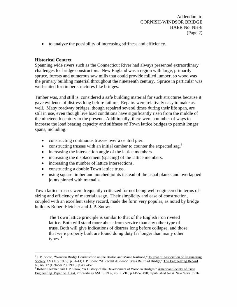
• constructing continuous trusses over a central pier. • constructing trusses with an initial camber to counter the expected sag.3 • increasing the intersection angle of the lattice members. • increasing the displacement (spacing) of the lattice members. • increasing the number of lattice intersections. • constructing a double Town lattice truss. • using square timber and notched joints instead of the usual planks and overlapped
joints pinned with treenails. Town lattice trusses were frequently criticized for not being well-engineered in terms of sizing and efficiency of material usage. Their simplicity and ease of construction, coupled with an excellent safety record, made the form very popular, as noted by bridge builders Robert Fletcher and J. P. Snow:
The Town lattice principle is similar to that of the English iron riveted lattice. Both will stand more abuse from service than any other type of truss. Both will give indications of distress long before collapse, and those that were properly built are found doing duty far longer than many other types. 4
3 J. P. Snow, “Wooden Bridge Construction on the Boston and Maine Railroad,” Journal of Association of Engineering Society XV (July 1895): p.31-43; J. P. Snow, “A Recent All-wood Truss Railroad Bridge,” The Engineering Record. 60, no. 17 (October 23, 1909): p.456-457. 4 Robert Fletcher and J. P. Snow, “A History of the Development of Wooden Bridges,” American Society of Civil Engineering. Paper no. 1864, Proceedings ASCE. 1932, vol. LVIII, p.1455-1498, republished No.4, New York. 1976.

Addendum to CORNISH-WINDSOR BRIDGE
HAER No. NH-8 (Page 3)
Town lattice structures have to be considered–as they were conceived–holistically. The elements’ geometries are interlinked. With their many redundant paths for stress, they are statically indeterminant structures, meaning that a thorough, detailed stress analysis is possible only by considering the effects of deflection on each member. Lattice displacement is dependent on floor beam capacity, as the usual design placed only one beam in one lattice panel. Town lattice structures are commonly analyzed using the concept of an “equivalent girder.” Detailed computer-based linear finite element analyses have shown that the overall behavior is close to that of an arch, as the assembly of compression diagonals and upper chords resembles an arch, while the lower chords mimic the role have the role of a tie-rod, and the mid-span lattice webs work as suspension ties. Notched Squared Timber Town Lattice Bridges Ithiel Town first patented the simplest form of his lattice truss, the plank lattice truss, in 1820. The need to carry heavier loads, such as railway trains, prompted Town to develop and patent lattice trusses with multiple lattice webs in 1935.5 Four years later, he received yet another patent, this one for a stronger lattice truss that used squared timber with interlocking notches at the lattice joints. This notched squared timber Town lattice truss also was significantly stiffer than plank trusses and suitable for longer spans. Being more complex and expensive to build than their plank lattice cousins, far fewer were built, and only a handful survive. Figures 1 and 2 illustrate the single and multiple web forms of the Town lattice truss. The notched squared timber variant could be built in both forms.
5 In his patent, Town included double, triple, and quadruple lattice webs, but no examples of the latter two are known. See J. G. James, The Evolution of Wooden Bridge Trusses to 1850, p.175.

Addendum to CORNISH-WINDSOR BRIDGE
HAER No. NH-8 (Page 4)
Figure 1. Town’s 1820 plank lattice truss patent.
Figure 2. Town’s 1835 multiple plank lattice truss patent

Addendum to CORNISH-WINDSOR BRIDGE
HAER No. NH-8 (Page 5)
Historic Simplified Calculation of Town Lattice Structures The simplest analytical method for a Town lattice truss is the equivalent plate girder analysis. It is useful for height/span ratios similar to those found in large wide-flange beams, whose behavior is similar. A more sophisticated calculation involves deconstructing the Town lattice truss into an intersecting series of Warren trusses.6 Since treenailed joints are more similar to riveted than to pinned joints, this deconstruction actually forms multiple indeterminate structures, so in practice, the same equivalent girder method was often used as a simplified way to analyze Warren trusses, too.7 Existing iron lattice structural reports have included comparisons between the results of simplified multiple Warren “quintangular” truss analysis and computer-aided calculations. These have shown good agreement between the two methods.8 Most lattice trusses consist of four Warren trusses and are referred to as “quadrangular.” Using this terminology, the Cornish-Windsor Bridge would be a “sextangular” structure. THE CORNISH-WINDSOR BRIDGE Present Configuration The Cornish-Windsor Bridge is 450’-5” long at floor level (407’ total clear-span length), consisting of two spans of 204’ and 203’. It has an overall width of 24’ and a roadway width of 19’-6”. Its vertical clearance above the roadway is 12’-9”. The lattice trusses are built of 6 x 8” Eastern Spruce timbers placed at the general diagonal offsetting distance of 4”, with the classical double lower and double upper chord pattern. Chord members originally were composed of two 3 x 10” and 5 x 10” members that were partially replaced by laminated wooden members in 1989. The overall appearance of the truss is shown in Figure 3, and the properties of Eastern Spruce used in the analysis are listed in Table 1.
6 The Warren truss was patented by the British bridge builder James Warren with Theobald Monzani in 1848, and it was being used in the United States by the 1860s. See Historic American Engineering Record (HAER), National Park Service, U.S. Department of the Interior, “Upper Bridge at Slate Run,” HAER No. PA-460, p6-7. 7 Morgan W. Davies, The Theory and Practice of Bridge Construction in Timber, Iron and Steel (London: Macmillan and Co. Limited, 1908), p.73-85. 8 Historic American Engineering Record, (HAER), National Park Service, U.S. Department of the Interior, “Structural Study of Pennsylvania Historic Bridges,” HAER No. PA-478.

Addendum to CORNISH-WINDSOR BRIDGE
HAER No. NH-8 (Page 6)
Figure 3. General arrangement of the Cornish-Windsor Town lattice truss structure9
Table 1. Properties of Eastern Spruce
mass per unit volume 4.40E-08 kip / in3 0.9133 lb / ft3 weight per unit volume 1.70E-05 kip / in3 29.3976 lb / ft3 modulus of elasticity 1340.277 kip / in2 1.93E+08 lb / ft2
Poisson ratio 0.372 0.372
As originally built, the lattice-chord and lattice-lattice joints were notched ¼”. Details of these joints are shown in Figure 3. The lattice-lattice joints interlocked the members, but lattice members typically butted against chord members.
Figure 4. Notched squared lattice joint details
9 Unless noted, structural drawings from David C. Fischetti’s 1989 rehabilitation.
Addendum to CORNISH-WINDSOR BRIDGE
HAER No. NH-8 (Page 7)
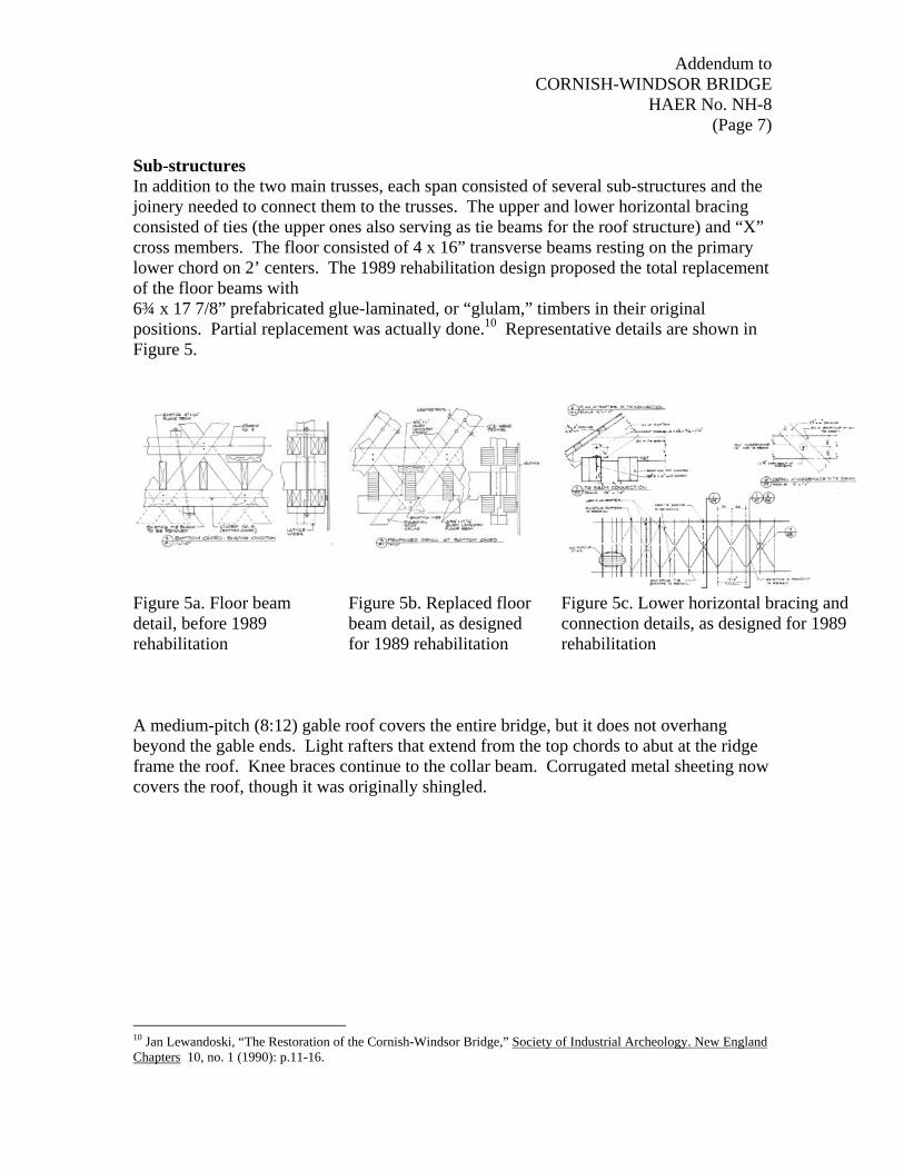
Sub-structures In addition to the two main trusses, each span consisted of several sub-structures and the joinery needed to connect them to the trusses. The upper and lower horizontal bracing consisted of ties (the upper ones also serving as tie beams for the roof structure) and “X” cross members. The floor consisted of 4 x 16” transverse beams resting on the primary lower chord on 2’ centers. The 1989 rehabilitation design proposed the total replacement of the floor beams with 6¾ x 17 7/8” prefabricated glue-laminated, or “glulam,” timbers in their original positions. Partial replacement was actually done.10 Representative details are shown in Figure 5.
Figure 5a. Floor beam detail, before 1989 rehabilitation
Figure 5b. Replaced floor beam detail, as designed for 1989 rehabilitation
Figure 5c. Lower horizontal bracing and connection details, as designed for 1989 rehabilitation
A medium-pitch (8:12) gable roof covers the entire bridge, but it does not overhang beyond the gable ends. Light rafters that extend from the top chords to abut at the ridge frame the roof. Knee braces continue to the collar beam. Corrugated metal sheeting now covers the roof, though it was originally shingled.
10 Jan Lewandoski, “The Restoration of the Cornish-Windsor Bridge,” Society of Industrial Archeology. New England Chapters 10, no. 1 (1990): p.11-16.

Addendum to CORNISH-WINDSOR BRIDGE
HAER No. NH-8 (Page 8)
Figure 6. Upper horizontal bracing system and roof detail, as designed for 1989 rehabilitation
Characteristic Features of the Cornish-Windsor Bridge Being a notched squared timber Town lattice truss bridge, the Cornish-Windsor Bridge is characterized by a set of specific joints that are not found in a simple plank lattice structure. Additionally, the 1989 rehabilitation introduced a set of new members, joints, and details, including:
• new joints to improve structural continuity in the chords. • new glulam replacement elements and connections to original chord timbers. • new sister lattice members in selected locations.
The lattice web, a “sixtangular” system (seven horizontal lines of joints), was already quite stiff for a wooden truss. The truss’s 15’ height, which is significantly greater than the 12 – 13’ height of most plank lattice bridges, also contributes to this stiffness. The diagonal end design of the truss, shown in Figure 7, is also unusual, though not entirely unique. This figure also includes end joint details, some of which may well be unique to this bridge.

Addendum to CORNISH-WINDSOR BRIDGE
HAER No. NH-8 (Page 9)
Figure 7. End lattice and joint details
Simple butting of chord members was always one of the weaker points of Town lattice trusses, even if combined with shear blocks. Therefore their 1989 elimination from the structure in areas with the highest stresses improved the structure’s overall behavior, transforming it into a safe bridge for HS15-44 loading condition.

Addendum to CORNISH-WINDSOR BRIDGE
HAER No. NH-8 (Page 10)
Interestingly, the chord-lattice and lattice-lattice joints were originally assembled with threaded fasteners, two for lower chord and new lattice sister joints and one elsewhere. Not known is whether this use of nuts and bolts in place of treenails was standard practice for notched square timber Town trusses, or unique to the Cornish-Windsor Bridge. Summary of the 1989 Rehabilitation The rehabilitation, designed by structural engineer David C. Fischetti, assured the bridge an HS15-44 load capacity through insertion of industrial grade, prefabricated, structural glued laminated (glulam) timber chords and floor beams in areas of high tensile stress. 11 Although desirable from the historic perspective, the “replacement-in-kind” solution could not be adopted because of the unavailability of solid timbers in the size and quality required. “Replacement-in-kind” would also have retained the butt and shear-block joints, which would have unacceptably reduced the net chord areas and increased stresses. The lengths of glulam elements were selected to place splices at locations of minimum stress. Notches for shear blocks and butt splices were removed from the chord members in maximum stress areas to maximize the net chord section. Figure 8 shows how the new elements were integrated into the existing structure.
Figure 8. Before and after rehabilitation transverse sections, showing existing and new chord elements.
11 David C. Fischetti, Glulam Chord Replacement Alternative Cornish-Windsor Bridge, Cornish, NH – Windsor, VT, S-4134. Prepared for: State of New Hampshire. Commissioner of the Department of Transportation Concord, New Hampshire: January 19, 1988.

Addendum to CORNISH-WINDSOR BRIDGE
HAER No. NH-8 (Page 11)
Figure 9. New sister lattice webs.
Larger glulam floor beams replaced the original ones. A number of deteriorated lattice members needed reinforcement, especially at certain joints, so the historically common approach of adding sister members insertion was taken, as shown in Figure 9. Abutments and bolster beams were also reinforced. ANALYSIS OF THE CORNISH-WINDSOR BRIDGE Notched Squared Timber Versus Plank Lattice Members Three-dimensional structural models are complex to design and configure properly. The three-dimensional mathematical model of the Cornish-Windsor Bridge developed for use with the STRAAD structural analysis software consisted of 1,132 joints and 2,143 members. To get an initial sense of how the basic behavior of a notched squared timber (hereafter termed “timber”) Town truss compared to a plank truss, the first set of analyses used a proven, three-dimensional model the author developed for another, similar HAER project involving the Contoocook railroad bridge. Analyses were performed for the following cases:
• continuous truss with two, 71’ spans, plank members (Contoocook design). • continuous truss with two, 71’ spans, timber members. • single truss, 142’ span, plank members. • single truss, 142’ span, timber members.
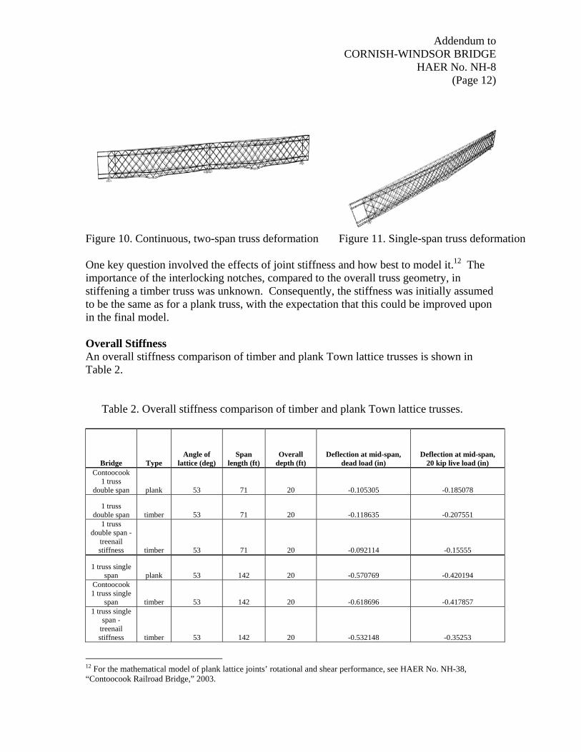
Figures 10 and 11 are plots showing the general nature of deformation for the continuous and single-span trusses, respectively.
Addendum to CORNISH-WINDSOR BRIDGE
HAER No. NH-8 (Page 12)
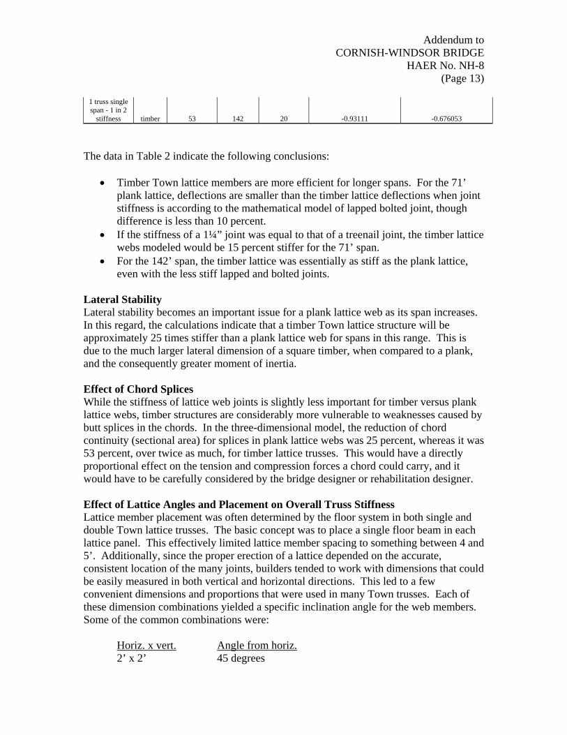
Figure 10. Continuous, two-span truss deformation Figure 11. Single-span truss deformation One key question involved the effects of joint stiffness and how best to model it.12 The importance of the interlocking notches, compared to the overall truss geometry, in stiffening a timber truss was unknown. Consequently, the stiffness was initially assumed to be the same as for a plank truss, with the expectation that this could be improved upon in the final model. Overall Stiffness An overall stiffness comparison of timber and plank Town lattice trusses is shown in Table 2.
Table 2. Overall stiffness comparison of timber and plank Town lattice trusses.
Bridge Type Angle of
lattice (deg) Span
length (ft) Overall
depth (ft) Deflection at mid-span,
dead load (in) Deflection at mid-span,
20 kip live load (in) Contoocook
1 truss double span plank 53 71 20 -0.105305 -0.185078
1 truss double span timber 53 71 20 -0.118635 -0.207551
1 truss double span -
treenail stiffness timber 53 71 20 -0.092114 -0.15555
1 truss single span plank 53 142 20 -0.570769 -0.420194
Contoocook 1 truss single
span timber 53 142 20 -0.618696 -0.417857 1 truss single
span - treenail stiffness timber 53 142 20 -0.532148 -0.35253
12 For the mathematical model of plank lattice joints’ rotational and shear performance, see HAER No. NH-38, “Contoocook Railroad Bridge,” 2003.
Addendum to CORNISH-WINDSOR BRIDGE
HAER No. NH-8 (Page 13)
1 truss single span - 1 in 2
stiffness timber 53 142 20 -0.93111 -0.676053
The data in Table 2 indicate the following conclusions:
• Timber Town lattice members are more efficient for longer spans. For the 71’ plank lattice, deflections are smaller than the timber lattice deflections when joint stiffness is according to the mathematical model of lapped bolted joint, though difference is less than 10 percent.
• If the stiffness of a 1¼” joint was equal to that of a treenail joint, the timber lattice webs modeled would be 15 percent stiffer for the 71’ span.
• For the 142’ span, the timber lattice was essentially as stiff as the plank lattice, even with the less stiff lapped and bolted joints.
Lateral Stability Lateral stability becomes an important issue for a plank lattice web as its span increases. In this regard, the calculations indicate that a timber Town lattice structure will be approximately 25 times stiffer than a plank lattice web for spans in this range. This is due to the much larger lateral dimension of a square timber, when compared to a plank, and the consequently greater moment of inertia. Effect of Chord Splices While the stiffness of lattice web joints is slightly less important for timber versus plank lattice webs, timber structures are considerably more vulnerable to weaknesses caused by butt splices in the chords. In the three-dimensional model, the reduction of chord continuity (sectional area) for splices in plank lattice webs was 25 percent, whereas it was 53 percent, over twice as much, for timber lattice trusses. This would have a directly proportional effect on the tension and compression forces a chord could carry, and it would have to be carefully considered by the bridge designer or rehabilitation designer. Effect of Lattice Angles and Placement on Overall Truss Stiffness Lattice member placement was often determined by the floor system in both single and double Town lattice trusses. The basic concept was to place a single floor beam in each lattice panel. This effectively limited lattice member spacing to something between 4 and 5’. Additionally, since the proper erection of a lattice depended on the accurate, consistent location of the many joints, builders tended to work with dimensions that could be easily measured in both vertical and horizontal directions. This led to a few convenient dimensions and proportions that were used in many Town trusses. Each of these dimension combinations yielded a specific inclination angle for the web members. Some of the common combinations were:
Horiz. x vert. Angle from horiz.
2’ x 2’ 45 degrees

Addendum to CORNISH-WINDSOR BRIDGE
HAER No. NH-8 (Page 14)
2’ x 2½’ 51 degrees 2’ x 3’ 60 degrees 3’ x 4’ 53 degrees Some observations are qualitatively apparent.
• For the same number of member interfaces, greater angles will result in a greater
overall height and, thus, greater stiffness. • Angles less than 30 degrees or greater than 60 degrees would change the forces on
the web members from predominantly axial forces to predominantly shear, which would not be desirable.
The structures shown in Figure 12 (a) through 12 (e) were quantitatively analyzed,
using a two-dimensional model, to determine their deflections and characteristic forces. In all cases, both plank and timber versions were been analyzed. Table 3 contains the data.

Addendum to CORNISH-WINDSOR BRIDGE
HAER No. NH-8 (Page 15)
(a) 53° – 4’10 ¾” interax lattice distance – 7 joint lines
(b) 53° – 4’10 ¾” interax lattice distance – 5 joint lines
(c) 45° – 4’ interax lattice distance – 7 joint lines
(d) 60° – 4’ interax lattice distance – 7 joint lines
(e) 60° – 5’ interax lattice distance – 7 joint lines
Figure 12. Town lattice trusses for quantitative comparison.

Addendum to CORNISH-WINDSOR BRIDGE
HAER No. NH-8 (Page 16)
Table 3. Deflections and characteristic forces for selected Town plank and timber trusses.
Bridge Truss Type
Angle of lattice (deg)
Interax lattice Span (ft)
Overall depth (ft)
Deflection at mid-span, 20 kip live load (in)
Contoocook 1 truss single span three chords plank 53 4' 10 3/4" 142 20 -0.3484 Contoocook 1 truss single span plank 53 4' 10 3/4" 142 20 -0.35734 Contoocook 1 truss single span timber 53 4' 10 3/4" 142 20 -0.32176 5 intersection Contoocook 1 truss single span plank 53 4' 10 3/4" 142 16.58 -0.48792 5 intersection Contoocook 1 truss single span timber 53 4' 10 3/4" 142 16.58 -0.4503 7 intersection 45 angle, 4' inteax plank 45 4' 142 12 -0.81512 7 intersection 45 angle, 4' interax timber 45 4' 142 12 -0.77642 7 intersection 60 angle, 4' interax plank 60 4' 142 15 -0.57499 7 intersection 60 angle, 4' interax timber 60 4' 142 15 -0.53175 7 intersection 60 angle, 5' interax plank 60 5' 142.5 18.75 -0.4416 7intersection 60 angle, 5' interax timber 60 5' 142.5 18.75 -0.41333
These data yield the following conclusions:
• Changing the overall height by 23.76 percent (by reducing the number of joint
lines) resulted in a stiffness reductions of 36.5 percent for plank trusses and 40 percent for timber trusses.
Addendum to CORNISH-WINDSOR BRIDGE
HAER No. NH-8 (Page 17)
• The overall stiffness of a timber truss depends less on the rotational stiffness of
the joints than on its overall height. • The overall stiffness of a timber truss depends less on the web member angle than
on its overall height. • A given change in height that causes the web member angle to be above 45
degrees is not as effective in increasing stiffness as when the angle can be maintained below 45 degrees.
• Maintaining the web member angle while changing the interax (lattice center offset distance) is the least efficient way to obtain greater stiffness by increasing the overall height.
Creep Effect Wood has time-dependent stress-strain behavior. For example, creep is the increase of strain over time in wood at a constant stress. Creep occurs in three stages. The first stage of creep deformation occurs when the structure is initially loaded, the second stage is reached when the rate of creep begins to approach zero, and the third stage, which occurs under large live loads over long periods of time, is when the rate of creep increases quickly to failure. The second stage is typically reached within a short period of time, and it can last for many years.13 An accurate analysis of creep would require a viscous stress-strain model that was not available, so no attempt was made to model the effect of creep in the wood of the truss. Historic data concerning the Cornish-Windsor Bridge indicate that it has been characterized by increasing sag (97/8” in 1912 to 17” in 1986). This is a strong indicator of creep in the joints. During rehabilitation work in 1989, a 24” positive camber was introduced to each span. As expected, first-stage creep reduced the camber by a little more than 2” during the first few months of service after the temporary supports had been removed.14 Although the Cornish-Windsor spans are quite long, these data suggest that the notched joints of a timber truss are more susceptible to rotation because of creep deformation than the treenail joints of a plank truss. Part of this results from the nature of wood itself, but a portion is likely due to notched joints being less-precisely made than treenail joints, which could easily increase localized contact forces where joint notch faces bear against one another at a slight angle that prevents initial full-face contact. SPECIAL CONSIDERATIONS ON TIMBER LATTICE WEBS AND JOINTS Joint Details
13 Forest Products Laboratory, Wood Handbook, Wood as an Engineering Material, 1999 14 Lewandoski, “The Restoration of the Cornish-Windsor Bridge,” p.11-16.

Addendum to CORNISH-WINDSOR BRIDGE
HAER No. NH-8 (Page 18)
As has been demonstrated above, timber lattice trusses achieve their overall stiffness more through member stiffness than joint stiffness. Even so, the truss could have benefited from more careful design and execution of the notches. The notches are too shallow. This resulted in small contact areas, and since the joints tend to twist, they work under a triangular compression stress distribution. The stress is limited by perpendicular on-grain compression, which is highest in the darkened corners of Figure 13. The resulting capacity for shear is only 1.425 kip.
Figure 13. Notched joint detail. Note darkened areas of
high contact stress at the joint corners.
In many forms of wood construction, it is common to notch each intersecting member one-half its thickness, termed a halved scarf joint. This optimizes the joint’s rotational strength, providing about three times the rotational and crushing/shear capacity, and it puts both members in the same plane. It does, however, reduce the local sectional area of each member by one-half as well, which similarly reduces the member’s axial strength in tension, an important consideration in timber lattice truss design. Some comparisons were made to plank trusses, particularly those joined with dual treenails. Since the joints of the Cornish-Windsor Bridge were working only under triangular compression and were relatively shallow, their rotational stiffness was only about one-seventh of the rotational stiffness of a dual treenail joint. Treenail connections, particularly accurately made ones using two treenails, would have been more efficient than the seemingly more-modern bolted connections actually used in the Cornish-Windsor Bridge, but they would have been difficult to execute consistently well on such a large scale.

Addendum to CORNISH-WINDSOR BRIDGE
HAER No. NH-8 (Page 19)
Lateral Stiffness and Stability The lateral stability of timber lattice trusses is higher than that of plank lattice trusses. This is due to the greater stiffness of square members compared to planks, and it depends very little on the rotational stiffness of the web joints. Since the need for lateral stiffness increases dramatically as span length increases, this was probably the primary reason the notched squared timber design was selected for the Cornish-Windsor Bridge. Splices in Lower Chords and the Addition of Glulam Timber This analysis indicated that continuity in the lower (tension) chords was more important for timber lattice trusses than for their plank lattice cousins. Whether because of engineering analysis or an understanding based on experience, the builder of the Cornish-Windsor Bridge included shear blocks—pieces not normally used in plank lattice trusses—to improve the strength continuity of the chords. Through engineering thoughts or just based on carpentry knowledge the original designers included shear blocks (generally not used in plank lattice trusses). Clearly, the builders understood the importance of chord continuity, even though, at only 1” thick, the original shear blocks were undersized. The installation of glulam continuous chords in the primary strain areas during the 1989 rehabilitation corrected these deficiencies and assured the necessary safety factor for modern live loads. The introducing of glulam elements necessarily included new mechanical joints and fasteners. Compared to the original joint work, these modern joints were well engineered and executed. The only remaining question, one that only time can answer, is the long-term compatibility of these modern components and connections with the original materials and joints.