addendum no. 5 - welcome to the city of dallas,...
TRANSCRIPT
ADDENDUM NO. 5
Per Addendum No. 2, BIDS WILL BE RECEIVED AT THE OFFICE OF THE PURCHASING
AGENT OF THE CITY OF DALLAS, TEXAS, CITY HALL, ROOM 3FN, 1500 MARILLA STREET,
UNTIL 1:00 PM ON FRIDAY, THE 18th DAY OF DECEMBER, 2015, AND WILL BE PUBLICLY
OPENED AND READ AT 2:00 PM ON FRIDAY, THE 18th DAY OF DECEMBER, 2015, BY THE
PURCHASING AGENT. LATE BIDS WILL BE RETURNED UNOPENED. The deadline for
prebid inquiries has passed and further inquiries may be ignored.
1. Attached are responses to questions received via email. (Addendum No. 5 p-3 through p-5)
2. Notice to Bidders – Item O – Computer-Generated Proposal: Delete page AFB-10 and
replace with the attached AFB-10. (Addendum No. 5 p-6)
3. Special Provision A-53 – LAND ACQUISITION: Delete page A-110 of the Special Provisions
and replace with the attached page A-110. (Addendum No. 5 p-7). The restriction from
starting work on Site A before July 31, 2017, was removed; work on Site A may commence
on November 1, 2016, per Section 01100.
4. The attached “Insurance Requirements” modify insurance requirements found elsewhere in
the documents, and in case of conflict, the most stringent requirements apply.
(Addendum No. 5 p-8 through p-12)
5. Proposal Form – Delete the page S11-2 (issued with Addendum #3) and replace with the
attached page S11-2. (Addendum No. 5 p-13) There is no Cast Stone Cap in Option 1 on
Junius Street. The top of the wall will be Stone Veneer (Bid Item 4009B), and the quantity of
this item is increased on the revised page S11-2 to include this quantity of the top veneer
and to add the quantity of veneer on the face of the wall below grade, which was inadvertently
excluded from the original quantity take-off.
6. Section 01900 – DISPUTE REVIEW BOARD: Delete page 01900-14 and replace with the
attached page 01900-14. (Addendum No. 5 p-14) This adds Halff and Parsons to the parties
immune to liability associated with the DRB.
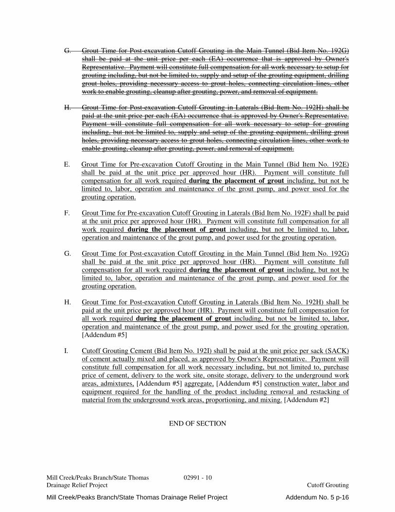
7. Section 02991 – CUTOFF GROUTING: Delete pages 02991-9 and 02991-10 and replace
with the attached pages 02991-9 and 02991-10. (Addendum No. 5 p-15 and p-16)
8. Section 15059 – SUMP PUMPS AND ACCESSORIES: Delete page 15059-2 and replace
with the attached page 15059-2. (Addendum No. 5 p-17) This removes the requirement for
approval of an “or equal” sump pump prior to bid opening; substitutions will considered after
award of the contract.
9. Section 16380-MEDIUM VOLTAGE LOAD INTERRUPTER SWITCHGEAR: Delete Section
16380 in its entirety. Section 16380 is replaced by Section 16482.
10. Section 16482 – MEDIUM VOLTAGE MOTOR CONTROL CENTERS: Add new Technical
Specification Section 16482. (Addendum No. 5 p-18 through p-31)
Mill Creek/Peaks Branch/State Thomas Drainage Relief Project Addendum No. 5 p-1

11. The “Grade Number 3 Course Aggregate Gradation Analysis” shall be as shown below; this
table takes precedence over the gradation analysis shown in Table 303.3.3.1.9.(d).COD,
Table 303.3.3.2.9.(d).COD, and Table 303.3.3.3.9.(d).COD in the 2011 Addendum.
12. The Geotechnical Data Report is revised per the attached “Mill Creek / Peaks Branch
Drainage Relief Project – Addendum 2 – December 2015, to Geotechnical Data Report
(GDR) March 2014.” A “Rock Core Log Description Legend” was added to Appendix A.
(Addendum No. 5 p-32 through p-34)
13. Sheet CO-201 - Site O - Construction Site - Requirements: Delete Sheet CO-201 in its
entirety and replace with the attached Sheet CO-201. Additional surface property available
to the CONTRACTOR were added. (Addendum No. 5 p-35)
14. Sheet A4CN-001 – Estimated Project Quantities - Bid Alternate No. 4: Delete Sheet
A4CN-001 in its entirety and replace with the attached Sheet A4CN-001. Item No. 4009C
was deleted, and the quantity of Item No. 4009B was revised. (Addendum No. 5 p-36)
15. Sheet A4CD-306 - Bid Alternate No. 4 Site D - Drainage Junius Street: Delete Sheet
A4CD-306 in its entirety and replace with the attached Sheet A4CD-306. Item No. 4009C
was deleted, and the quantity of Item No. 4009B was revised. (Addendum No. 5 p-37)
Mill Creek/Peaks Branch/State Thomas Drainage Relief Project Addendum No. 5 p-2

ADDENDUM NO. 5 – QUESTIONS AND ANSWERS
1. QUESTION: In the GDR and GBR, “Hardness” is reported in psi. It appears that the Hardness Number measured by the Schmidt Hammer has been correlated to estimate Unconfined Compressive Strength in psi. The basis for the correlation is not provided. Please provide the correlation curve relating Hardness Number and Unconfined Compressive Strength. ANSWER: The correlation for all the hardness testing used was the manufacturer’s chart provided by Humboldt, please see Figure 4 below, which is copied from page 5 of the Product Manual for the Humboldt H-2987 Concrete Rebound Hammer. All testing was performed with the hammer in the vertical (downward) orientation, using curve “A.” Please note that Schmidt hammer results are intended only to provide comparative hardness of materials, not a measure of compressive strength. Uniaxial testing was performed for compressive strength, and the results of said uniaxial tests are presented in the GDR and GBR.
Mill Creek/Peaks Branch/State Thomas Drainage Relief Project Addendum No. 5 p-3

2. QUESTION: The Geotechnical Data Report (GDR), Section 3.4, on Page 3‐8 states the following: “Rock classifications were made in accordance with the International Society for Rock Mechanics Commission on Standardization of Laboratory and Field Tests (1981). The primary components of rock classification system are shown on the boring log legend in Appendix A.” Appendix A, however, contains no legend to provide this information. Please provide the described legend information, defining terms and ranges for terms used on the boring logs including degree of fracturing (or fracture spacing), roughness, aperture, fracture fill material, and degree of weathering. ANSWER: A legend of terminology used for the rock mass and rock discontinuity descriptions is included with Addendum 2 to the GDR, which is part of this Addendum #5. (Addendum #5 p-32 to p-34)
3. QUESTION: Would the Owner please consider adding a standard aggregate and delay damages liability cap to the Contract? ANSWER: No, there is no cap on aggregate and delay damages liability.
4. QUESTION: In Addendum No. 2, Page 10, under Contractor’s Safety Record, it states “The BIDDER must provide safety records and Experience Modifier Rate (EMR) from the local OSHA office in which the firm is located.” Are Bidders required to submit any additional safety information In addition to Safety Record Affidavit Form? If so, please specify. ANSWER: The only safety information required to be submitted with the Bid is a completed Form 8 for the Prime contractor only, or for a Joint Venture, a completed Form 8 for each member of the Joint Venture.
5. QUESTION: Aside from the experience and safety sections, no specific instructions were provided in the specs on how to submit as a Joint Venture. Please clarify how a Joint Venture firm should submit the proposal forms. ANSWER: A Joint Venture is a single entity with whom the City of Dallas would enter a contract if they are the successful bidder. The Proposal Forms are to be filled out as a single package irrespective of which Joint Venture partner, subcontractor, or supplier is doing the work. Experience presented must be the experience of the Joint Venture partner that will perform the work if the Joint Venture is the successful bidder, but no further information is required with the Bid.
6. QUESTION: Tunnel Boring Machine (TBM) Mobilization is paid under Item 110Z, which is limited to the acquisition, transportation, setup, TBM spare parts, and any component that is mounted directly onto the TBM. Please clarify which Pay Item covers the disassembly and de-mobilization of the TBM Machine. ANSWER: Demobilization of the TBM shall be incidental to Item No. 147, Tunnel Type A, B, C and D – TBM Excavation and Rock Dowel Support.
7. QUESTION: Section 02950 Item 4.2.A.1 describes that payment for the TBM Excavation and the rock dowels for Tunnel Types A, B, C and D will be paid under item 147. This bid item’s quantities include the entire length of the Tunnel excavation. Section 02950 Item 4.2.A.3 describes Bid Item 149 payment that includes the TBM excavation for Tunnel Types E and F. Please clarify the duplication of excavation quantities between Bid Items 147 and 149. ANSWER: Payment for Tunnel Types E and F include excavation. There is no plan quantity for Item No. 149; this item and a quantity of 80 Linear Feet is included to establish a unit price in the event that steel rib initial support is required. Bid items will be paid on installed quantities verified in the field.
Mill Creek/Peaks Branch/State Thomas Drainage Relief Project Addendum No. 5 p-4
8. QUESTION: There appears to be an error in the payment section of Section 02991. Bid Items 192E through 192H are for Grout Time; however, the payment paragraphs 4.2.E through 4.2.H describe payment for mobilization. Please clarify. ANSWER: A revision to Section 02991 is included with this Addendum #5 to correct the descriptions for payment of Bid Items 192E through 192H. (Addendum No. 5 p-15 and p-16)
9. QUESTION: Will requests for product substitutions be approved during the bid process? ANSWER: Substitution requests from the Contractor will only be considered after contract award and in accordance with the contract provisions.
10. QUESTION: Where is Detail 5 shown on Sheet MD-401 located? What is the pay item for the 3” Lueder Limestone Cap shown on the top of the retaining wall? Where is the stone veneer wall located on Sheet LD-101? ANSWER: Detail 5 shown on Sheet MD-401 is for the stone veneer retaining wall shown on Sheet A4CD-306. Payment for the 3” Lueder Limestone Cap shall be at the unit price bid for Item 4009B, Stone Veneer. There is no stone veneer wall on Sheet LD-101; the stone veneer and cast stone cap are for the drop shaft; refer to Detail 3 on Sheet MD-401. (Refer to Addendum No. 3 and this Addendum No. 5 for additional information.)
11. QUESTION: Section 15060, paragraph 2.1.G requires approval by a nationally recognized testing agency such as U.L. or F.M. Can this requirement be removed for the pumps? ANSWER: No; the pumps must be approved by a nationally recognized testing agency in accordance with Section 15060, Dewatering Pumps and Accessories.
12. QUESTION: After consultation with the McCommas Landfill as suggested by the bid documents, we were informed that the tipping fee for clean soil at McCommas is $21.50 per ton, and that at this time there are no special rates for materials from this project. Will the City of Dallas consider negotiating a special rate for this project in order to reduce such costs? ANSWER: Surplus excavated material, trash, and debris emanating from the Project shall become property of the CONTRACTOR, and CONTRACTOR shall properly and legally dispose of said material offsite. There is no requirement to dispose of materials at the McCommas Bluff Landfill, and there is currently no plan to negotiate a special rate to dispose of materials at the McCommas Bluff Landfill.
13. QUESTION: Is a permit required on the total project or just the dewatering pump station? ANSWER: A building permit is required only for the Dewatering Station building, not for the entire project.
Mill Creek/Peaks Branch/State Thomas Drainage Relief Project Addendum No. 5 p-5
NOTICE TO BIDDERS (continued)
Mill Creek/Peaks Branch/State Thomas AFB-10 Drainage Relief Project Advertisement for Bids and Notice to Bidders
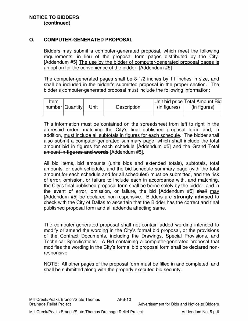
O. COMPUTER-GENERATED PROPOSAL
Bidders may submit a computer-generated proposal, which meet the following requirements, in lieu of the proposal form pages distributed by the City. [Addendum #5] The use by the bidder of computer-generated proposal pages is an option for the convenience of the bidder. [Addendum #5]
The computer-generated pages shall be 8-1/2 inches by 11 inches in size, and
shall be included in the bidder’s submitted proposal in the proper section. The bidder’s computer-generated proposal must include the following information:
Item
number Quantity Unit Description Unit bid price
(in figures) Total Amount Bid
(in figures)
This information must be contained on the spreadsheet from left to right in the aforesaid order, matching the City’s final published proposal form, and, in addition, must include all subtotals in figures for each schedule. The bidder shall also submit a computer-generated summary page, which shall include the total amount bid in figures for each schedule [Addendum #5] and the Grand Total amount in figures and words [Addendum #5].
All bid items, bid amounts (units bids and extended totals), subtotals, total amounts for each schedule, and the bid schedule summary page (with the total amount for each schedule and for all schedules) must be submitted, and the risk of error, omission, or failure to include each in accordance with, and matching, the City’s final published proposal form shall be borne solely by the bidder; and in the event of error, omission, or failure, the bid [Addendum #5] shall may [Addendum #5] be declared non-responsive. Bidders are strongly advised to check with the City of Dallas to ascertain that the Bidder has the correct and final published proposal form and all addenda affecting same. The computer-generated proposal shall not contain added wording intended to modify or amend the wording in the City’s formal bid proposal, or the provisions of the Contract Documents, including the Drawings, Special Provisions, and Technical Specifications. A Bid containing a computer-generated proposal that modifies the wording in the City’s formal bid proposal form shall be declared non-responsive.
NOTE: All other pages of the proposal form must be filled in and completed, and
shall be submitted along with the properly executed bid security.
Mill Creek/Peaks Branch/State Thomas Drainage Relief Project Addendum No. 5 p-6

Mill Creek/Peaks Branch/State Thomas A-110 Drainage Relief Project Section A – Special Provisions
A-52 DALLAS CITY CODE
The CONTRACTOR shall adhere to all the requirements of The Dallas City Code, which is available at the following URL: http://www.amlegal.com/nxt/gateway.dll/Texas/dallas/volumei/preface?f=templates$fn=default.htm$3.0$vid=amlegal:dallas_tx The CONTRACTOR should pay particular attention to the following:
1. Chapter 5A - Air Pollution 2. Chapter 7A - Anti-Litter Regulations, Sections 7A-6 and 7A-7.1 3. Chapter 15B - Equal Employment Opportunity Contract Compliance 4. Chapter 18 - Municipal Solid Wastes, Sections 18-29 through 18-52 5. Chapter 19 - Health and Sanitation, Sections 19-118. through 19-118.8 6. Chapter 30 - Noise 7. Chapter 36 - Poles and Wires 8. Chapter 51A - Part II of the Dallas Development Code, Section 51A-6.101.,
and Sections 51A-6.103. through 51A-6.107., and Sections 51A-10.136. through 51A-10.140.
A-53 LAND ACQUISITION
[Addendum #4] Fee-simple property and sub-surface easements have been acquired from the beginning of the tunnel to Station 18+40. All required fee-simple property and sub-surface easement acquisitions from Station 18+40 to Station 133+00 will be obtained on or before January 1, 2017. All required fee-simple property and sub-surface easement acquisitions from Station 133+00 to the end of the tunnel at Station 271+85 will be obtained on or before March 1, 2017. [Addendum #5] Construction on the lot at Site A, on which the dewatering station will be constructed, may not begin until July 31, 2017. [Addendum #5] All required fee-simple property acquisitions and sub-surface easements downstream of (east of) Tunnel Station 133+00 have been obtained. The OWNER will provide to BIDDERs, at least 7 calendar days prior to opening bids, the locations of other parcels for which fee-simple or easement acquisitions is required and the date by which each will be acquired. The OWNER owns the lot on which the dewatering station will be constructed; however, construction on said lot may not commence until a Specific Use Permit (SUP) is obtained. The OWNER will provide to BIDDERs, at least 7 calendar days prior to opening bids, the date by which said SUP will be obtained [Addendum #4]
Mill Creek/Peaks Branch/State Thomas Drainage Relief Project Addendum No. 5 p-7
12/4/15 Page 1 of 5 Mill Creek/Peaks Branch Drainage Tunnel
Construction
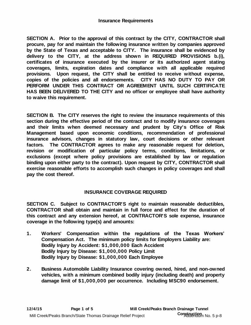
Insurance Requirements
SECTION A. Prior to the approval of this contract by the CITY, CONTRACTOR shall
procure, pay for and maintain the following insurance written by companies approved
by the State of Texas and acceptable to CITY. The insurance shall be evidenced by
delivery to the CITY, at the address shown in REQUIRED PROVISIONS b.(i),
certificates of insurance executed by the insurer or its authorized agent stating
coverages, limits, expiration dates and compliance with all applicable required
provisions. Upon request, the CITY shall be entitled to receive without expense,
copies of the policies and all endorsements. CITY HAS NO DUTY TO PAY OR
PERFORM UNDER THIS CONTRACT OR AGREEMENT UNTIL SUCH CERTIFICATE
HAS BEEN DELIVERED TO THE CITY and no officer or employee shall have authority
to waive this requirement.
SECTION B. The CITY reserves the right to review the insurance requirements of this
section during the effective period of the contract and to modify insurance coverages
and their limits when deemed necessary and prudent by City's Office of Risk
Management based upon economic conditions, recommendation of professional
insurance advisors, changes in statutory law, court decisions or other relevant
factors. The CONTRACTOR agrees to make any reasonable request for deletion,
revision or modification of particular policy terms, conditions, limitations, or
exclusions (except where policy provisions are established by law or regulation
binding upon either party to the contract). Upon request by CITY, CONTRACTOR shall
exercise reasonable efforts to accomplish such changes in policy coverages and shall
pay the cost thereof.
INSURANCE COVERAGE REQUIRED
SECTION C. Subject to CONTRACTOR'S right to maintain reasonable deductibles,
CONTRACTOR shall obtain and maintain in full force and effect for the duration of
this contract and any extension hereof, at CONTRACTOR'S sole expense, insurance
coverage in the following type(s) and amounts:
1. Workers' Compensation within the regulations of the Texas Workers’
Compensation Act. The minimum policy limits for Employers Liability are:
Bodily Injury by Accident: $1,000,000 Each Accident
Bodily Injury by Disease: $1,000,000 Policy Limit
Bodily Injury by Disease: $1,000,000 Each Employee
2. Business Automobile Liability Insurance covering owned, hired, and non-owned
vehicles, with a minimum combined bodily injury (including death) and property
damage limit of $1,000,000 per occurrence. Including MSC90 endorsement.
Mill Creek/Peaks Branch/State Thomas Drainage Relief Project Addendum No. 5 p-8

12/4/15 Page 2 of 5 Mill Creek/Peaks Branch Drainage Tunnel
Construction
3. Commercial General Liability Insurance including, but not limited to,
Premises/Operations, Personal & Advertising Injury, Products/Completed
Operations, Independent Contractors and Contractual Liability with minimum
combined bodily injury (including death) and property damage limits of
$1,000,000 per occurrence, $2,000,000 general aggregate.
The policy shall include coverage extended to apply to products/completed
operations and XCU hazards. The Completed Operations coverage must be
maintained for a minimum of one (1) year after final completion and acceptance
of the Work, with evidence of same filed with Owner. Owner shall be named
as additional insured using the broadest form of endorsement available, with
such status extended to include the extension of the completed operations
coverage as described above. The policy shall include endorsement CG2503
Amendment of limits (designated project or premises) in order to extend the
policy’s limits specifically to the project in question.
4. Umbrella or Excess Liability Insurance providing coverage following form of the
primary liability coverages described in 1, 2, and 3 above, with minimum
combined bodily injury (including death) and property damage limit of
$25,000,000 per occurrence and $25,000,000 annual aggregate.
5. All Risk Builders Risk Policy including, but not limited to, Fire, Extended
Coverage, Vandalism and Malicious Mischief, Flood (if located in a flood zone)
and Theft in an amount equal to one hundred percent (100%) of the contract
cost of the project in question. The policy shall include materials delivered and
labor performed for the project in question. The policy shall be written jointly in
the names of the Owner, Contractor teams, subcontractors, and sub-
subcontractors as their interests may appear. The policy shall have
endorsements as follows:
a. This insurance shall be specific as to coverage and not contributing
insurance with any permanent insurance maintained on the property.
All Risk Builders Risk Policy to include Flood, Earth Movement, Earthquake,
Seismic Event for the Project including:
1) All limits shall be for each claim or occurrence. Annual aggregates for
Flood, and Earthquake are acceptable. The policy shall not include any
condition of reinstatement of the limit(s) other than the stated
aggregates
2) London Engineering Group (LEG) 2 type or equivalent coverage for design
error, faulty workmanship and/or faulty materials
Mill Creek/Peaks Branch/State Thomas Drainage Relief Project Addendum No. 5 p-9

12/4/15 Page 3 of 5 Mill Creek/Peaks Branch Drainage Tunnel
Construction
3) Coverage against damage or loss caused by any type of earth
movement, subsidence, sinkhole, flood, fire, theft, collapse, explosion,
vandalism and malicious mischief, machinery accidents and operational
testing
4) Coverage for removal of debris (with a sublimit not less than
$25,000,000 for debris removal), and insuring the buildings, structures,
machinery, equipment, materials, facilities, fixtures and all other
properties constituting a part of the Project
5) Transit coverage with sub-limits sufficient to insure the full replacement
value of any key equipment item
6) Coverage with a limit of insurance for tunneling works with a minimum
limit of $50,000,000
7) The policy shall include coverage for the Tunnel Boring Machine (if used
in the execution of this project). The limit of insurance shall reflect the
purchase price of the Tunnel Boring Machine.
Coverage shall be for the replacement value thereof for ‘‘all risks’’ of direct
physical loss or damage, including earth movement, earthquake, subsidence,
sinkhole and flood coverage, with a minimum limit of liability equal to one
hundred percent (100%) of the contract cost of the project, plus ‘‘soft costs
expense cover’’ (including interest or other financing costs incurred by Owner,
attorneys’ fees and fees and other costs associated with such damage or loss
and with any Governmental Approvals). Coverage shall include a minimum
sublimit on such soft cost/delay expenses of $25,000,000 with a maximum
delay deductible of 30 days. The policy shall be written jointly in the names of
the Owner, Contractor teams, subcontractors, and sub-subcontractors as their
interest may appear. The policy shall have endorsements as follows:
Deductibles or self insured retentions for all other perils and shall not exceed
i. $250,000 for all losses unless otherwise stated
ii. $1,000,000 Tunneling Works
iii. Flood coverage deductibles shall not exceed 5% of the value at
risk at the time of loss subject to a minimum of $250,000
whichever is greater
iv. Named Windstorm to including ensuing damage as a result of
storm surge 5% of the value at risk at the time of loss subject to a
minimum of $250,000 whichever is greater
v. Earth Movement or Earthquake 5% of the value at risk at the time
of loss subject to a minimum of $250,000 whichever is greater
vi. Tunnel Boring Machine deductible not to exceed $250,000
The Builders Risk coverage shall be written without risk of liability of
Indemnified Parties for payment and without deduction for depreciation. There
shall be no coinsurance penalty provision in the policy.
Mill Creek/Peaks Branch/State Thomas Drainage Relief Project Addendum No. 5 p-10
12/4/15 Page 4 of 5 Mill Creek/Peaks Branch Drainage Tunnel
Construction
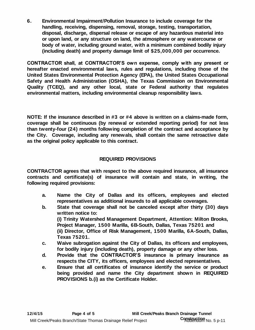
6. Environmental Impairment/Pollution Insurance to include coverage for the
handling, receiving, dispensing, removal, storage, testing, transportation,
disposal, discharge, dispersal release or escape of any hazardous material into
or upon land, or any structure on land, the atmosphere or any watercourse or
body of water, including ground water, with a minimum combined bodily injury
(including death) and property damage limit of $25,000,000 per occurrence.
CONTRACTOR shall, at CONTRACTOR’S own expense, comply with any present or
hereafter enacted environmental laws, rules and regulations, including those of the
United States Environmental Protection Agency (EPA), the United States Occupational
Safety and Health Administration (OSHA), the Texas Commission on Environmental
Quality (TCEQ), and any other local, state or Federal authority that regulates
environmental matters, including environmental cleanup responsibility laws.
NOTE: If the insurance described in #3 or #4 above is written on a claims-made form,
coverage shall be continuous (by renewal or extended reporting period) for not less
than twenty-four (24) months following completion of the contract and acceptance by
the City. Coverage, including any renewals, shall contain the same retroactive date
as the original policy applicable to this contract.
REQUIRED PROVISIONS
CONTRACTOR agrees that with respect to the above required insurance, all insurance
contracts and certificate(s) of insurance will contain and state, in writing, the
following required provisions:
a. Name the City of Dallas and its officers, employees and elected
representatives as additional insureds to all applicable coverages.
b. State that coverage shall not be canceled except after thirty (30) days
written notice to:
(i) Trinity Watershed Management Department, Attention: Milton Brooks,
Project Manager, 1500 Marilla, 6B-South, Dallas, Texas 75201 and
(ii) Director, Office of Risk Management, 1500 Marilla, 6A-South, Dallas,
Texas 75201.
c. Waive subrogation against the City of Dallas, its officers and employees,
for bodily injury (including death), property damage or any other loss.
d. Provide that the CONTRACTOR’S insurance is primary insurance as
respects the CITY, its officers, employees and elected representatives.
e. Ensure that all certificates of insurance identify the service or product
being provided and name the City department shown in REQUIRED
PROVISIONS b.(i) as the Certificate Holder.
Mill Creek/Peaks Branch/State Thomas Drainage Relief Project Addendum No. 5 p-11

12/4/15 Page 5 of 5 Mill Creek/Peaks Branch Drainage Tunnel
Construction
SECTION D. (1) Without limiting any of the other obligations or liabilities of the
CONTRACTOR, the CONTRACTOR shall require each Subcontractor performing work
under the contract, at the Subcontractor's own expense, to maintain during the term
of the contract, levels of insurance that are necessary and appropriate for the services
being performed, comply with all applicable laws and are consistent with industry
standards. The Subcontractor’s liability insurance shall name the CONTRACTOR as
an additional insured. (2) The CONTRACTOR shall obtain and monitor the certificates
of insurance from each Subcontractor. The CONTRACTOR must retain the
certificates of insurance for the duration of the contract and shall have the
responsibility of enforcing insurance requirements among its subcontractors. The
CITY shall be entitled, upon request and without expense, to receive copies of these
certificates.
SECTION E. Approval, disapproval or failure to act by the CITY regarding any
insurance supplied by the CONTRACTOR or its subcontractors shall not relieve the
CONTRACTOR of full responsibility or liability for damages and accidents as set forth
in the contract documents. Neither shall the bankruptcy, insolvency nor denial of
liability by the insurance company exonerate the CONTRACTOR from liability.
INDEMNITY
The CONTRACTOR agrees to defend, indemnify and hold CITY, its officers, agents
and employees, harmless against any and all claims, lawsuits, judgements, costs and
expenses for personal injury (including death), property damage or other harm for
which recovery of damages is sought, suffered by any person or persons, that may
arise out of or be occasioned by CONTRACTOR'S breach of any of the terms or
provisions of this contract, or by any negligent or strictly liable act or omission of
CONTRACTOR, its officers, agents, employees, or subcontractors, in the performance
of this contract; except that the indemnity provided for in this paragraph shall not
apply to any liability resulting from the sole negligence or fault of CITY, its officers,
agents or employees and in the event of joint and concurrent negligence or fault of
CONTRACTOR and CITY, responsibility and indemnity, if any, shall be apportioned
comparatively in accordance with the laws of the State of Texas, without waiving
any governmental immunity available to the CITY under Texas law and without
waiving any defenses of the parties under Texas law. The provisions of this
paragraph are solely for the benefit of the parties hereto and are not intended to
create or grant any rights, contractual or otherwise, to any other person or entity.
Mill Creek/Peaks Branch/State Thomas Drainage Relief Project Addendum No. 5 p-12
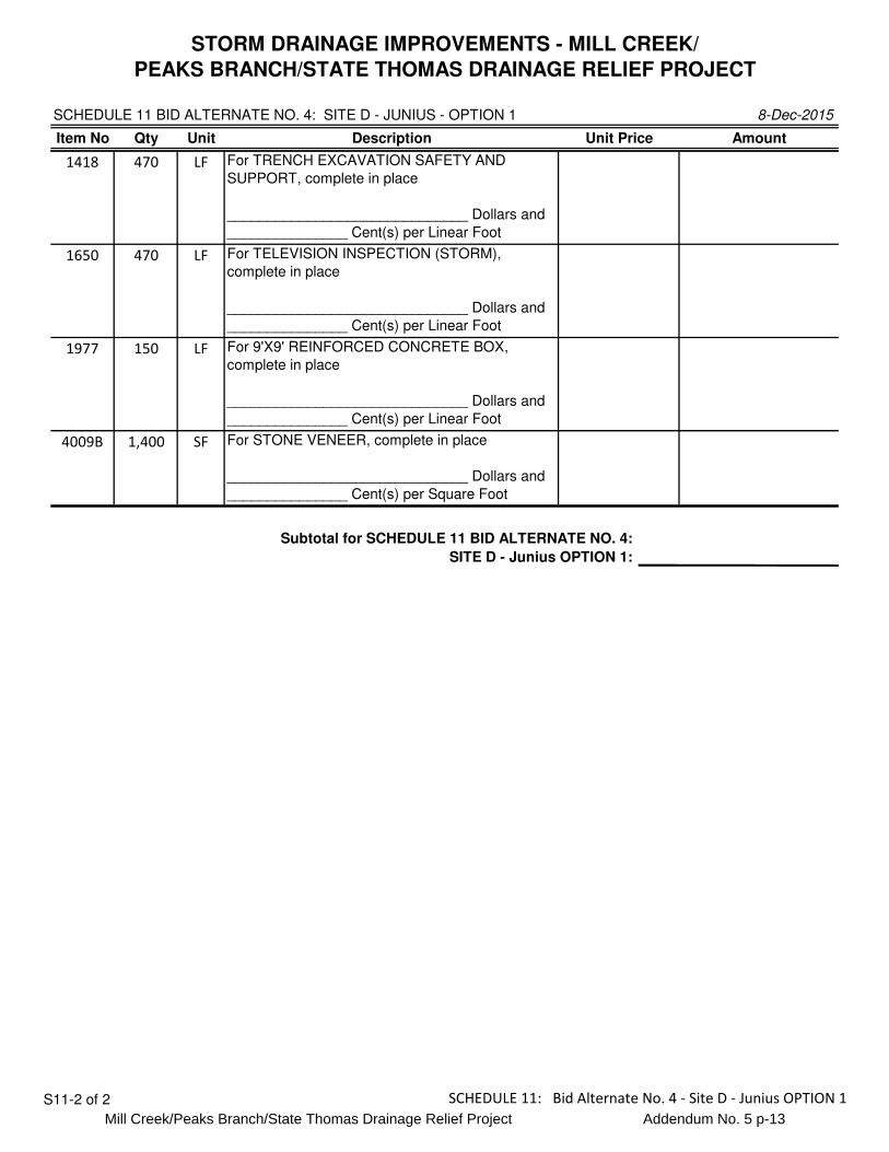
STORM DRAINAGE IMPROVEMENTS - MILL CREEK/
PEAKS BRANCH/STATE THOMAS DRAINAGE RELIEF PROJECT
SCHEDULE 11 BID ALTERNATE NO. 4: SITE D - JUNIUS - OPTION 1 8-Dec-2015
Item No Qty Unit Description Unit Price Amount
1418 470 LF For TRENCH EXCAVATION SAFETY AND
SUPPORT, complete in place
______________________________ Dollars and
_______________ Cent(s) per Linear Foot
1650 470 LF For TELEVISION INSPECTION (STORM),
complete in place
______________________________ Dollars and
_______________ Cent(s) per Linear Foot
1977 150 LF For 9'X9' REINFORCED CONCRETE BOX,
complete in place
______________________________ Dollars and
_______________ Cent(s) per Linear Foot
4009B 1,400 SF For STONE VENEER, complete in place
______________________________ Dollars and
_______________ Cent(s) per Square Foot
Subtotal for SCHEDULE 11 BID ALTERNATE NO. 4:
SITE D - Junius OPTION 1:
S11-2 of 2 SCHEDULE 11: Bid Alternate No. 4 - Site D - Junius OPTION 1
Mill Creek/Peaks Branch/State Thomas Drainage Relief Project Addendum No. 5 p-13

Mill Creek/Peaks Branch/State Thomas 01900 - 14 Three-Party Agreement
Drainage Relief Project Dispute Review Board
IX ASSIGNMENT
No party to this Agreement shall assign any duty established under this Agreement.
X. TERMINATION
A. This Agreement may be terminated by mutual agreement of the OWNER and
CONTRACTOR at any time upon not less than four weeks written notice to the
other parties.
B. Individual Board members may be terminated for violation of this agreement and/
or the requirements of Section 01900 by either the OWNER or the
CONTRACTOR, or for any reason by mutual agreement of both the OWNER and
the CONTRACTOR.
C. If a Board member resigns, is unable to serve, or is terminated, he or she shall be
replaced within five weeks in the same manner as he or she was originally selected,
and this Agreement shall be amended to reflect the member replacement.
XI LEGAL RELATIONS
A. The parties to this Agreement expressly acknowledge that each Board member, in
the performance of his or her duties on the DRB, is acting in the capacity of an
independent agent and not as an employee of the OWNER or the CONTRACTOR.
B. Board members shall not participate in subsequent dispute proceedings.
C. The OWNER and the CONTRACTOR acknowledge that each Board member is
acting in a capacity intended to facilitate the resolution of disputes. Accordingly, it
is agreed and acknowledged that, to the fullest extent permitted by law, each Board
member shall be accorded quasi-judicial immunity for any actions or decisions
associated with DRB activities.
D. Each Board member [Addendum #5], the OWNER, the CONTRACTOR, Halff
Associates, Inc., and Parsons; and their heirs, successors, and assigns, shall be held
harmless for any corporate, personal, or professional liability arising from or related
to DRB activities. To the fullest extent permitted by law, the OWNER and the
CONTRACTOR shall indemnify and hold harmless all Board members, Halff
Associates, Inc., and Parsons; and their heirs, successors, and assigns,
[Addendum #5] for claims, losses, demands, costs, and damages (including
reasonable attorney fees) for bodily injury, property damage, or economic loss
arising out of or related to Board members carrying out DRB activities. The
foregoing indemnity is a joint and several obligation.
E. Board members shall not assign any of the work of this assignment
F. Neither the OWNER nor CONTRACTOR may subpoena a Board member for any
purpose related to a dispute considered by the Board.
Mill Creek/Peaks Branch/State Thomas Drainage Relief Project Addendum No. 5 p-14

Mill Creek/Peaks Branch/State Thomas 02991 - 9
Drainage Relief Project Cutoff Grouting
4.2 Payment
A. Cutoff Grouting: Payment for cutoff grouting, as specified herein, shall be made at the unit
price per cubic yard (CY) of cutoff grout actually mixed and placed, as approved by the
Engineer. The unit price shall include all labor, materials, supplies and equipment necessary
to place the cutoff grout as specified herein.
A. Mobilization for Pre-excavation Cutoff Grouting in the Main Tunnel (Bid Item No. 192A)
will be paid at the unit price per each (EA) occurrence that is approved by Owner's
Representative. Payment will constitute full compensation for all work necessary to setup for
grouting including, but not be limited to, supply and setup of the grouting equipment, drilling
grout holes, providing necessary access to grout holes, connecting circulation lines, other
work to enable grouting, cleanup after grouting, power, and removal of equipment.
B. Mobilization for Pre-excavation Cutoff Grouting in Laterals (Bid Item No. 192B) will be
paid at the unit price per each (EA) occurrence that is approved by Owner's Representative.
Payment will constitute full compensation for all work necessary to setup for grouting
including, but not be limited to, supply and setup of the grouting equipment, drilling grout
holes, providing necessary access to grout holes, connecting circulation lines, other work to
enable grouting, cleanup after grouting, power, and removal of equipment.
C. Mobilization for Post-excavation Cutoff Grouting in the Main Tunnel (Bid Item No. 192C)
will be paid at the unit price per each (EA) occurrence that is approved by Owner's
Representative. Payment will constitute full compensation for all work necessary to setup for
grouting including, but not be limited to, supply and setup of the grouting equipment, drilling
grout holes, providing necessary access to grout holes, connecting circulation lines, other
work to enable grouting, cleanup after grouting, power, and removal of equipment.
D. Mobilization for Post-excavation Cutoff Grouting in Laterals (Bid Item No. 192D) will be
paid at the unit price per each (EA) occurrence that is approved by Owner's Representative.
Payment will constitute full compensation for all work necessary to setup for grouting
including, but not be limited to, supply and setup of the grouting equipment, drilling grout
holes, providing necessary access to grout holes, connecting circulation lines, other work to
enable grouting, cleanup after grouting, power, and removal of equipment.
[Addendum #5]
E. Grout Time for Pre-excavation Cutoff Grouting in the Main Tunnel (Bid Item No. 192E)
shall be paid at the unit price per each (EA) occurrence that is approved by Owner's
Representative. Payment will constitute full compensation for all work necessary to setup for
grouting including, but not be limited to, supply and setup of the grouting equipment, drilling
grout holes, providing necessary access to grout holes, connecting circulation lines, other
work to enable grouting, cleanup after grouting, power, and removal of equipment.
F. Grout Time for Pre-excavation Cutoff Grouting in Laterals (Bid Item No. 192F) shall be paid
at the unit price per each (EA) occurrence that is approved by Owner's Representative.
Payment will constitute full compensation for all work necessary to setup for grouting
including, but not be limited to, supply and setup of the grouting equipment, drilling grout
holes, providing necessary access to grout holes, connecting circulation lines, other work to
enable grouting, cleanup after grouting, power, and removal of equipment.
Mill Creek/Peaks Branch/State Thomas Drainage Relief Project Addendum No. 5 p-15
Mill Creek/Peaks Branch/State Thomas 02991 - 10
Drainage Relief Project Cutoff Grouting
G. Grout Time for Post-excavation Cutoff Grouting in the Main Tunnel (Bid Item No. 192G)
shall be paid at the unit price per each (EA) occurrence that is approved by Owner's
Representative. Payment will constitute full compensation for all work necessary to setup for
grouting including, but not be limited to, supply and setup of the grouting equipment, drilling
grout holes, providing necessary access to grout holes, connecting circulation lines, other
work to enable grouting, cleanup after grouting, power, and removal of equipment.
H. Grout Time for Post-excavation Cutoff Grouting in Laterals (Bid Item No. 192H) shall be
paid at the unit price per each (EA) occurrence that is approved by Owner's Representative.
Payment will constitute full compensation for all work necessary to setup for grouting
including, but not be limited to, supply and setup of the grouting equipment, drilling grout
holes, providing necessary access to grout holes, connecting circulation lines, other work to
enable grouting, cleanup after grouting, power, and removal of equipment.
E. Grout Time for Pre-excavation Cutoff Grouting in the Main Tunnel (Bid Item No. 192E)
shall be paid at the unit price per approved hour (HR). Payment will constitute full
compensation for all work required during the placement of grout including, but not be
limited to, labor, operation and maintenance of the grout pump, and power used for the
grouting operation.
F. Grout Time for Pre-excavation Cutoff Grouting in Laterals (Bid Item No. 192F) shall be paid
at the unit price per approved hour (HR). Payment will constitute full compensation for all
work required during the placement of grout including, but not be limited to, labor,
operation and maintenance of the grout pump, and power used for the grouting operation.
G. Grout Time for Post-excavation Cutoff Grouting in the Main Tunnel (Bid Item No. 192G)
shall be paid at the unit price per approved hour (HR). Payment will constitute full
compensation for all work required during the placement of grout including, but not be
limited to, labor, operation and maintenance of the grout pump, and power used for the
grouting operation.
H. Grout Time for Post-excavation Cutoff Grouting in Laterals (Bid Item No. 192H) shall be
paid at the unit price per approved hour (HR). Payment will constitute full compensation for
all work required during the placement of grout including, but not be limited to, labor,
operation and maintenance of the grout pump, and power used for the grouting operation.
[Addendum #5]
I. Cutoff Grouting Cement (Bid Item No. 192I) shall be paid at the unit price per sack (SACK)
of cement actually mixed and placed, as approved by Owner's Representative. Payment will
constitute full compensation for all work necessary including, but not limited to, purchase
price of cement, delivery to the work site, onsite storage, delivery to the underground work
areas, admixtures, [Addendum #5] aggregate, [Addendum #5] construction water, labor and
equipment required for the handling of the product including removal and restacking of
material from the underground work areas, proportioning, and mixing. [Addendum #2]
END OF SECTION
Mill Creek/Peaks Branch/State Thomas Drainage Relief Project Addendum No. 5 p-16

Mill Creek/Peaks Branch/State Thomas 15059 - 2
Drainage Relief Project Sump Pumps and Accessories
1.4 Quality Standards
A. All submersible pumps specified in this Section shall be furnished by a single supplier who
shall assume sole responsibility for providing complete, operating systems designed for long
life with minimum required maintenance, meeting requirements specified herein and as
shown on the Drawings.
B. Manufacturer shall provide written certification that the equipment provided under this
Specification has been amply designed and is suitable for these service conditions.
C. Pumps and appurtenances, including the pump, motor, guide system and wiring, shall be
suitable for operation and approved by a national approved testing agency for explosion-
proof service. The system shall be rated for Class 1, Division 2 service as determined by the
National Electrical Code and approved by a nationally recognized testing agency (U.L. or
F.M.).
D. Manufacturers offering products that comply with these specifications include:
1. Xylem Water Solutions, Flygt
2. KSB Pumps, Inc
3. Or equal, approved in writing by Engineer and Owner. [Addendum #5] prior to bid
opening date. [Addendum #5]
1.5 Submittals
A. Dimensional Shop Drawings of the installed systems.
B. Manufacturer’s Certifications.
C. Mill certificates of materials used in the construction of pumps shall be submitted to the
engineer prior to factory witness testing of the pumps.
D. Relevant experience references per requirements of 1.3(B).
E. Manufacturer’s data: Dimensions, materials; size and location of all loads imposed on
supporting structures; size and location of any concrete blockouts; size and location of
anchor bolts, certified setting plans, with tolerances, for anchor bolts and any required
clearances.
F. Factory testing procedures, sketch of test setup and results of certified performance and
witness testing.
G. Field testing procedures, equipment to be used and calibration certificates. Submit a
minimum of two weeks prior to field testing.
H. Data regarding pump and motor characteristics and performance including
1. Guaranteed performance curves (prior to fabrication and testing) based on actual
shop tests of mechanically similar pump, showing they meet specified requirements
for head, capacity, horsepower, efficiency and NPSHR.
2. Provide curves for a single unit only for units of same size and type
3. Provide catalog performance curves at required speed showing maximum and
minimum impeller diameters available.
I. Submit curves for guaranteed performance, certified test and witness tests on 8 ½ by 11 –
inch sheets, one curve per sheet.
J. Certified Results: hydrostatic testing and dynamic balancing.
K. Test Results: Pump shop and motor shop results.
L. Bearing Life: Certified by the pump manufacturer. Include design data.
M. Complete wiring and control diagrams.
N. List of recommended spare parts and supplies. List shall include current unit prices and
source of supply.
O. Executed copy of the 5-year preventative maintenance and service agreement.
P. Qualifications of field service technician.
Q. Location of nearest authorized pump service center.
R. Operation and maintenance manuals.
Mill Creek/Peaks Branch/State Thomas Drainage Relief Project Addendum No. 5 p-17

Mill Creek/Peaks Branch/State Thomas 16482 - 1
Drainage Relief Project Medium Voltage Motor Control Centers
SECTION 16482
MEDIUM VOLTAGE MOTOR CONTROL CENTERS
PART 1 GENERAL
1.01 SCOPE OF WORK
A. The Contractor shall furnish and install assemblies of Class E2 medium voltage motor
control centers (MVMCCs), together with appurtenances, complete and operable, as
specified herein and as shown on the Contract Drawings.
B. Motor control centers shall be sized to include all equipment, spares and spaces shown on the
Drawings.
1.02 RELATED WORK
A. Section 16000 Electrical – General Provisions
B. Section 16045 Electrical Support Hardware
C. Section 16105 Power System Study
D. Section 16120 Wires and Cables (600 Volt Maximum)
E. Section 16121 Medium Voltage Cables
F. Section 16195 Power Metering and Protective Relays
G. Section 16196 Low Voltage Surge Protective Devices (SPDs)
1.03 SUBMITTALS
A. Submittals shall be made in accordance with the requirements of Division 1, Section 16000
and as specified herein.
B. Provide systems engineering to produce coordination curves, showing coordination between
breakers and/or fuses submitted, such that protective device coordination is accomplished.
Such curves and settings shall be included as a part of these submittals.
C. Submittals shall also contain information on related equipment to be furnished under this
Specification but described in the related Sections listed in the Related Work paragraph
above. Incomplete submittals not containing the required information on the related
equipment will also be returned unreviewed.
D. The original MVMCC equipment manufacturer shall create all MVMCC shop drawings,
including all wiring diagrams, in the manufacturer’s engineering department. All MVMCC
shop drawings shall bear the original equipment manufacturer’s MVMCC logo, drawing file
numbers, and shall be maintained on file in the manufacturer’s MVMCC archive file system.
Photocopies of the Engineer’s ladder schematics are unacceptable as shop drawings.
Mill Creek/Peaks Branch/State Thomas Drainage Relief Project Addendum No. 5 p-18
Mill Creek/Peaks Branch/State Thomas 16482 - 2
Drainage Relief Project Medium Voltage Motor Control Centers
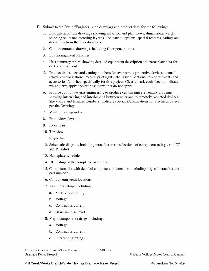
E. Submit to the Owner/Engineer, shop drawings and product data, for the following:
1. Equipment outline drawings showing elevation and plan views, dimensions, weight,
shipping splits and metering layouts. Indicate all options, special features, ratings and
deviations from the Specifications.
2. Conduit entrance drawings, including floor penetrations.
3. Bus arrangement drawings.
4. Unit summary tables showing detailed equipment description and nameplate data for
each compartment.
5. Product data sheets and catalog numbers for overcurrent protective devices, control
relays, control stations, meters, pilot lights, etc. List all options, trip adjustments and
accessories furnished specifically for this project. Clearly mark each sheet to indicate
which items apply and/or those items that do not apply.
6. Provide control systems engineering to produce custom unit elementary drawings
showing interwiring and interlocking between units and to remotely mounted devices.
Show wire and terminal numbers. Indicate special identifications for electrical devices
per the Drawings.
7. Master drawing index
8. Front view elevation
9. Floor plan
10. Top view
11. Single line
12. Schematic diagram, including manufacturer’s selections of component ratings, and CT
and PT ratios.
13. Nameplate schedule
14. UL Listing of the completed assembly.
15. Component list with detailed component information, including original manufacturer’s
part number.
16. Conduit entry/exit locations
17. Assembly ratings including:
a. Short-circuit rating
b. Voltage
c. Continuous current
d. Basic impulse level
18. Major component ratings including:
a. Voltage
b. Continuous current
c. Interrupting ratings
Mill Creek/Peaks Branch/State Thomas Drainage Relief Project Addendum No. 5 p-19

Mill Creek/Peaks Branch/State Thomas 16482 - 3
Drainage Relief Project Medium Voltage Motor Control Centers
19. Descriptive bulletins
20. Product data sheets.
21. Number and size of cables per phase, neutral if present, ground and all cable terminal
sizes.
22. Switchboard floor mat
23. Instruction and renewal parts books.
24. Itemized list of spare parts furnished specifically for this project, including quantities,
description and part numbers.
F. Factory Tests. Submittals shall be made for factory tests specified herein.
G. Field Test Reports. Submittals shall be made for field tests specified herein.
H. Operation and Maintenance Manuals.
1. Operation and maintenance manuals shall include the following information:
a. Manufacturer’s contact address and telephone number for parts and service.
b. Instruction books and/or leaflets
c. Recommended renewal parts list
d. Record Documents for the information required by the Submittals paragraph above.
I. The manufacturer shall submit for approval, a training agenda for all training specified
herein. Training agenda shall not be submitted until final approval of the Operation and
Maintenance Manual.
1.04 REFERENCE CODES AND STANDARDS
A. The medium voltage motor control centers and all components in this specification shall be
designed and manufactured according to latest revision of the following standards (unless
otherwise noted):
1. ANSI/IEEE C57.13, Standard Requirements for Instrument Transformers.
2. IEEE C37.90, Standard for Relays and Relay Systems Associated with Electric Power
Apparatus
3. NEMA SG 2, High Voltage Fuses
4. ANSI/NEMA ICS 6 – Enclosures for Industrial Controls and Systems
5. NEMA ICS 1 – General Standard for Industrial Control Systems
6. NEMA ICS 3, Part 2
7. UL 347 – High Voltage Industrial Control Equipment
8. NFPA 70 – National Electrical Code (NEC)
9. NFPA 70E – Standard For Electrical Safety in the Workplace
B. All equipment components and completed assemblies specified in this Section of the
Specifications shall bear the appropriate label of Underwriters Laboratories.
Mill Creek/Peaks Branch/State Thomas Drainage Relief Project Addendum No. 5 p-20

Mill Creek/Peaks Branch/State Thomas 16482 - 4
Drainage Relief Project Medium Voltage Motor Control Centers
1.05 QUALITY ASSURANCE
A. The manufacturer of this equipment shall have produced similar equipment for a minimum
period of ten (10) years. When requested by the Engineer, an acceptable list of installations
with similar equipment shall be provided demonstrating compliance with this requirement.
B. The manufacturer of the assembly shall be the manufacturer of the major components within
the assembly. All assemblies shall be of the same manufacturer. Equipment that is
manufactured by a third party and “brand labeled” shall not be acceptable.
C. All components and material shall be new and of the latest field proven design and in current
production. Obsolete components or components scheduled for immediate discontinuation
shall not be used.
D. Equipment submitted shall fit within the space shown on the Drawings. Equipment which
does not fit within the space is not acceptable.
E. For the equipment specified herein, the manufacturer shall be ISO 9001 2000 certified.
F. Equipment submitted shall fit within the space shown on the Drawings. Equipment which
does not fit within the space is not acceptable.
1.06 JOBSITE DELIVERY, STORAGE AND HANDLING
A. Prior to jobsite delivery, the Contractor shall have successfully completed all submittal
requirements, and present to the Owner/Engineer upon delivery of the equipment, an
approved copy of all such submittals. Delivery of incomplete constructed equipment, onsite
factory work, or failed factory tests will not be permitted.
B. Equipment shall be handled and stored in accordance with manufacturer's instructions. Two
(2) copies of these instructions shall be included with the equipment at time of shipment, and
shall be made available to the Contractor and Owner/Engineer.
C. Shipping groups shall be designed to be shipped by truck, rail, or ship. Indoor groups shall be
bolted to skids. Breakers and accessories shall be packaged and shipped separately.
D. Equipment shall be equipped to be handled by crane. Where cranes are not available,
equipment shall be suitable for skidding in place on rollers using jacks to raise and lower the
groups.
E. Equipment shall be installed in its permanent finished location shown on the Drawings
within seven (7) calendar days of arriving onsite. If the equipment cannot be installed within
seven (7) calendar days, the equipment shall not be delivered to the site, but stored offsite, at
the Contractor’s expense, until such time that the site is ready for permanent installation of
the equipment.
F. Where space heaters are provided in equipment, provide temporary electrical power and
operate space heaters during jobsite storage, and after equipment is installed in permanent
location, until equipment is placed in service.
Mill Creek/Peaks Branch/State Thomas Drainage Relief Project Addendum No. 5 p-21

Mill Creek/Peaks Branch/State Thomas 16482 - 5
Drainage Relief Project Medium Voltage Motor Control Centers
1.07 WARRANTY
A. The Manufacturer shall warrant the equipment to be free from defects in material and
workmanship for 3 years from date of final acceptance of the equipment. Within such period
of warranty, the Manufacturer shall promptly furnish all material and labor necessary to
return the equipment to new operating condition. Any work requiring shipping or
transporting of the equipment shall be performed by the Manufacturer, at no expense to the
Owner.
PART 2 PRODUCTS
2.01 MANUFACTURERS
A. Subject to compliance with the Contract Documents, the following Manufacturers are
acceptable:
1. Eaton
2. General Electric Co.
3. Square D
B. The listing of specific manufacturers above does not imply acceptance of their products that
do not meet the specified ratings, features and functions. Manufacturers listed above are not
relieved from meeting these specifications in their entirety.
2.02 RATINGS
A. The voltage, current and short circuit current ratings of the motor control centers shall be as
shown on the Drawings.
B. Motor controller ratings, NEMA 1A, with current limiting fuses, shall be as follows:
C. The vacuum contactor (NEMA 1A) shall be as follows:
2.3 Kv 2.3 kV 4 kV 4 kV
320A 640A 320A 640A
1200 Hp 2500 Hp 2250 Hp 4500 Hp
200 MVA 200 MVA 350 MVA 350 MVA
7200V Max. 400 Amperes 800 Amperes
Maximum Interrupting Current (3 Ops) 6000 Amps 9,000 Amps
Rated Current – Enclosed 320 Amps 640 Amps
Rated Current – Open 400 Amps 800 Amps
Short Time Current
30 Seconds 2400 A 4800 A
1 Second 6000 A 12,000 A
Impulse Withstand 60kV 60kV
Mill Creek/Peaks Branch/State Thomas Drainage Relief Project Addendum No. 5 p-22
Mill Creek/Peaks Branch/State Thomas 16482 - 6
Drainage Relief Project Medium Voltage Motor Control Centers
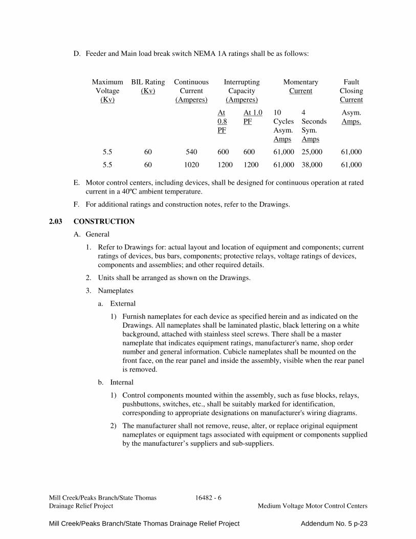
D. Feeder and Main load break switch NEMA 1A ratings shall be as follows:
E. Motor control centers, including devices, shall be designed for continuous operation at rated
current in a 40ºC ambient temperature.
F. For additional ratings and construction notes, refer to the Drawings.
2.03 CONSTRUCTION
A. General
1. Refer to Drawings for: actual layout and location of equipment and components; current
ratings of devices, bus bars, components; protective relays, voltage ratings of devices,
components and assemblies; and other required details.
2. Units shall be arranged as shown on the Drawings.
3. Nameplates
a. External
1) Furnish nameplates for each device as specified herein and as indicated on the
Drawings. All nameplates shall be laminated plastic, black lettering on a white
background, attached with stainless steel screws. There shall be a master
nameplate that indicates equipment ratings, manufacturer's name, shop order
number and general information. Cubicle nameplates shall be mounted on the
front face, on the rear panel and inside the assembly, visible when the rear panel
is removed.
b. Internal
1) Control components mounted within the assembly, such as fuse blocks, relays,
pushbuttons, switches, etc., shall be suitably marked for identification,
corresponding to appropriate designations on manufacturer's wiring diagrams.
2) The manufacturer shall not remove, reuse, alter, or replace original equipment
nameplates or equipment tags associated with equipment or components supplied
by the manufacturer’s suppliers and sub-suppliers.
Maximum
Voltage
(Kv)
BIL Rating
(Kv)
Continuous
Current
(Amperes)
Interrupting
Capacity
(Amperes)
Momentary
Current
Fault
Closing
Current
At
0.8
PF
At 1.0
PF
10
Cycles
Asym.
Amps
4
Seconds
Sym.
Amps
Asym.
Amps.
5.5 60 540 600 600 61,000 25,000 61,000
5.5 60 1020 1200 1200 61,000 38,000 61,000
Mill Creek/Peaks Branch/State Thomas Drainage Relief Project Addendum No. 5 p-23

Mill Creek/Peaks Branch/State Thomas 16482 - 7
Drainage Relief Project Medium Voltage Motor Control Centers
c. Special
1) Identification nameplates shall be white with black letters, caution nameplates
shall be yellow with black letters, and warning nameplates shall be red with
white letters.
5. Control Devices and Indicators
a. All operating control devices, indicators, and instruments shall be securely mounted
on the panel door. All controls and indicators shall be 30mm, corrosion resistant,
NEMA 4X/13, anodized aluminum or reinforced plastic. Booted control devices are
not acceptable. Auxiliary contacts shall be provided for remote run indication and
indication of each status and alarm condition. Additional controls shall be provided
as specified herein and as required by the detailed mechanical and electrical
equipment requirements.
b. Indicator lamps shall be LED type. For all control applications, indicator lamps shall
incorporate a push-to-test feature. Lens colors shall be as follows:
1) Red for ON and Breaker CLOSED.
2) Green for OFF and Breaker OPEN.
3) Amber for FAIL.
4) Blue for READY
5) White for POWER ON.
c. Mode selector switches (HAND-OFF-AUTO, LOCAL-OFF-REMOTE, etc) shall be
as shown on the Drawings. Units shall have the number of positions and contact
arrangements, as required. Each switch shall have an extra dry contact for remote
monitoring.
d. Pushbuttons, shall be as follows:
1) Red for STOP, Breaker OPEN, and mushroom Red for EMERGENCY STOP.
2) Green for START, and Breaker CLOSE.
3) Black for RESET.
e. Furnish nameplates for each device. All nameplates shall be laminated plastic, black
lettering on a white background, attached with stainless steel screws. Device
mounted nameplates are not acceptable.
6. Control and Instrument Power Transformers
a. Control power transformers shall be provided where shown on the Drawings.
Transformer shall be sized for the entire load, including space heaters, plus 25%
spare capacity, and shall be not less than 100VA.
b. Control power transformers shall be 120 volt grounded secondary. Primary side of
the transformer shall be fused in both legs. One leg of the transformer secondary
shall be solidly grounded and the other leg shall be fused.
Mill Creek/Peaks Branch/State Thomas Drainage Relief Project Addendum No. 5 p-24
Mill Creek/Peaks Branch/State Thomas 16482 - 8
Drainage Relief Project Medium Voltage Motor Control Centers
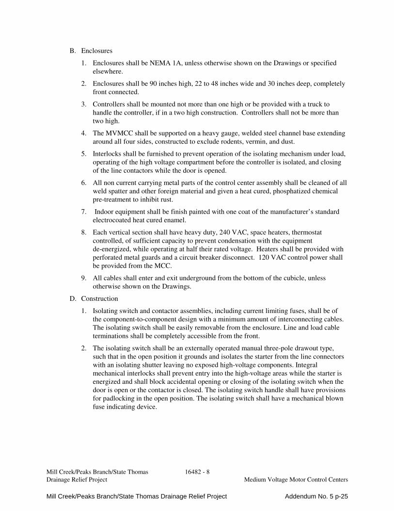
B. Enclosures
1. Enclosures shall be NEMA 1A, unless otherwise shown on the Drawings or specified
elsewhere.
2. Enclosures shall be 90 inches high, 22 to 48 inches wide and 30 inches deep, completely
front connected.
3. Controllers shall be mounted not more than one high or be provided with a truck to
handle the controller, if in a two high construction. Controllers shall not be more than
two high.
4. The MVMCC shall be supported on a heavy gauge, welded steel channel base extending
around all four sides, constructed to exclude rodents, vermin, and dust.
5. Interlocks shall be furnished to prevent operation of the isolating mechanism under load,
operating of the high voltage compartment before the controller is isolated, and closing
of the line contactors while the door is opened.
6. All non current carrying metal parts of the control center assembly shall be cleaned of all
weld spatter and other foreign material and given a heat cured, phosphatized chemical
pre-treatment to inhibit rust.
7. Indoor equipment shall be finish painted with one coat of the manufacturer’s standard
electrocoated heat cured enamel.
8. Each vertical section shall have heavy duty, 240 VAC, space heaters, thermostat
controlled, of sufficient capacity to prevent condensation with the equipment
de-energized, while operating at half their rated voltage. Heaters shall be provided with
perforated metal guards and a circuit breaker disconnect. 120 VAC control power shall
be provided from the MCC.
9. All cables shall enter and exit underground from the bottom of the cubicle, unless
otherwise shown on the Drawings.
D. Construction
1. Isolating switch and contactor assemblies, including current limiting fuses, shall be of
the component-to-component design with a minimum amount of interconnecting cables.
The isolating switch shall be easily removable from the enclosure. Line and load cable
terminations shall be completely accessible from the front.
2. The isolating switch shall be an externally operated manual three-pole drawout type,
such that in the open position it grounds and isolates the starter from the line connectors
with an isolating shutter leaving no exposed high-voltage components. Integral
mechanical interlocks shall prevent entry into the high-voltage areas while the starter is
energized and shall block accidental opening or closing of the isolating switch when the
door is open or the contactor is closed. The isolating switch handle shall have provisions
for padlocking in the open position. The isolating switch shall have a mechanical blown
fuse indicating device.
Mill Creek/Peaks Branch/State Thomas Drainage Relief Project Addendum No. 5 p-25

Mill Creek/Peaks Branch/State Thomas 16482 - 9
Drainage Relief Project Medium Voltage Motor Control Centers
3. Current limiting power fuses shall be provided with special fatigue proof elements that
allow the elements to absorb the expansions and contractions created by the heating and
cooling associated with severe cycling as is typical with motor starting. The fuses shall
include visible fuse condition indicators. The fuses shall incorporate special time/current
characteristics for motor service allowing proper coordination with the contactor and
overload relay for maximum motor protection. This coordination shall be such that under
a low-fault condition the interrupting rating and dropout time of the contactor shall be
properly coordinated with all possible fuse sizes to eliminate contactor racing. The
power fuses shall be mounted to permit easy inspection and replacement without starter
disassembly.
E. Busses
1. When starters are grouped together in a lineup, the horizontal main bus shall be located
in its own separate, 12-inch high enclosure and isolated from the starters. Each phase
shall be insulated. To allow for ease of maintenance or extension of lineups without
disassembling starters, the main bus shall be front, top and side accessible.
2. Starters shall be connected by an insulated vertical bus.
3. All bus bars shall be tin-plated copper, rated as shown on the Drawings
4. Provide a 1/4 x 2-inch ground bus throughout the entire lineup. Ground bus shall also be
supplied in upper compartments of 2-high starters and be bus connected to the ground
bus supplied in the lower compartments.
F. Wiring
1. All control wire shall be UL/CSA approved.
2. Standard control wire shall be 14GA, stranded, tin-plated, red, dual-rated type XLPE
(3173) 125 degrees C, SIS 90 degrees C.
3. Current transformer circuits shall utilize #12 wire with the same characteristics as above.
Provide shorting blocks for all current transformers.
4. Provide “plug-in” terminal blocks, rated 600 V, 50 A with “clamping collar.”
5. Wire markers shall be a molded plastic “clip-sleeve” type.
6. “Clamping-collar” type terminals shall be used to terminate control wiring. Current
transformer circuits shall be provided with ring-type terminals where applicable.
7. All field wiring shall be tagged and coded with an identification number as shown on the
Drawings. Coding shall be typed on a heat shrinkable tube applied to each end showing
origination and destination of each wire. The marking shall be permanent, non-smearing,
solvent-resistant type similar to Raychem TMS-SCE, or equal.
8. Terminations shall be completely accessible from the front.
Mill Creek/Peaks Branch/State Thomas Drainage Relief Project Addendum No. 5 p-26

Mill Creek/Peaks Branch/State Thomas 16482 - 10
Drainage Relief Project Medium Voltage Motor Control Centers
2.04 MAIN SECTION
A. General
1. The MVMCC main sections shall include the main switch, metering and power feeder
entrance to the MVMCC. Where a power feeder entrance is shown on the Drawings, the
power feeder entrance section shall be provided. Provide bus extensions and
compression lugs for number and size of incoming cables as shown on the Drawings.
B. Main Switches and Feeder Switches
1. Furnish, where shown on the contract drawings, three-pole manually operated quick-
make, quick-break load break switches or integrated metal enclosed breakers.
2. The fixed-mounted switches shall fit in one-half of a standard 90-inch high, 36-inch wide
vertical structure, when supplied with 400 A or smaller fuses. Provide mechanical
interlocks such that the switch door cannot be opened when the switch is on, and when
the door is open the switch cannot be closed. A safety screen shall be provided behind
the switch door.
C. Lightning Arresters and Surge Capacitors
1. Provide three intermediate type lightning arresters and surge capacitors on each
incoming line where shown on the Drawings. Arresters and capacitors shall be factory
installed.
D. Furnish lugs for incoming line feeders, sizes as specified. Allow adequate clearance for
bending and terminating of cable size and type specified.
2.07 METERING AND PROTECTIVE RELAYS
A. Furnish where shown on the Drawings, a Power Quality Meter (PM1), for each Main or
Feeder Switch, as shown on the Drawings and as specified in Section 16195 Power Metering
and Protective Relays.
2.08 SPARE PARTS
A. Provide the following spare parts:
1. 3 – Control fuses of type used.
2. One dozen each of cover bolts, spring nuts and door fasteners.
3. One quart of touch-up paint.
B. Spare parts shall be boxed or packaged for long term storage and clearly identified on the
exterior of package. Identify each item with manufacturers name, description and part
number
2.09 ACCESSORIES
A. Provide the following accessories:
1. Furnish and install a non-conducting floor mat, minimum 3/8 inch thick by 3 feet wide,
meeting ANSI/ASTM D-178-01 Type 2 Class 3, Wearwell 702 or equal, and extending
the full length of the equipment lineup.
Mill Creek/Peaks Branch/State Thomas Drainage Relief Project Addendum No. 5 p-27

Mill Creek/Peaks Branch/State Thomas 16482 - 11
Drainage Relief Project Medium Voltage Motor Control Centers
2.10 FACTORY TESTING
A. The Motor Control Center shall be completely assembled, wired, and adjusted at the factory
and shall be given the manufacturer’s routine shop tests and any other additional operational
test to insure the workability and reliable operation of the equipment.
B. Prior to factory testing, the manufacturer shall check to see that all selections and settings
required by the Power System Study Engineer have been performed.
C. Factory test equipment and test methods shall conform to the latest applicable requirements
of ANSI, IEEE, UL, and NEMA standards.
D. The operational test shall include the proper connection of supply and control voltage and, as
far as practical, a mockup of simulated control signals and control devices shall be fed into
the boards to check for proper operation.
E. The manufacturer shall provide three (3) certified copies of factory test reports as specified
in Paragraph 1.03D.
PART 3 EXECUTION
3.01 MANUFACTURER’S REPRESENTATIVE
A. Provide the services of a qualified factory-trained manufacturer's field engineer to assist the
Contractor in installation and start-up of the equipment specified under this Section for a
period of not less than 2 working days, with not less than one working day per motor control
center. The manufacturer's field engineer shall provide technical direction and assistance to
the Contractor in general assembly of the equipment, connections and adjustments, and
testing of the assembly and components contained therein.
B. The Contractor shall provide three (3) copies of the manufacturer's field testing report.
3.02 INSTALLER’S QUALIFICATIONS
A. Installer shall be specialized in installing medium voltage motor control centers with
minimum 5 years documented experience. Experience documentation shall be submitted for
approval prior to beginning work on this project.
3.03 EXAMINATION
A. Examine installation area to assure there is enough clearance to install the equipment.
B. Housekeeping pads shall be included for the motor control centers as detailed on the
Drawings with the exception of motor control centers which are to be installed adjacent to an
existing unit. Housekeeping pads for these (if used) should match the existing installation.
C Check concrete pads and baseplates for uniformity and level surface.
D. Verify that the equipment is ready to install.
E. Verify field measurements are as instructed by manufacturer.
3.04 INSTALLATION
A. The Contractor shall install all equipment per the manufacturer's recommendations and
Contract Drawings.
B. Install required safety labels.
Mill Creek/Peaks Branch/State Thomas Drainage Relief Project Addendum No. 5 p-28
Mill Creek/Peaks Branch/State Thomas 16482 - 12
Drainage Relief Project Medium Voltage Motor Control Centers
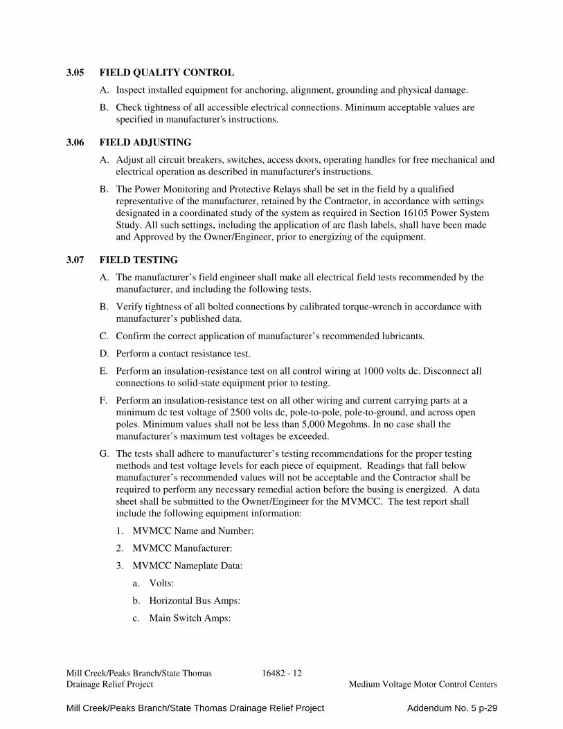
3.05 FIELD QUALITY CONTROL
A. Inspect installed equipment for anchoring, alignment, grounding and physical damage.
B. Check tightness of all accessible electrical connections. Minimum acceptable values are
specified in manufacturer's instructions.
3.06 FIELD ADJUSTING
A. Adjust all circuit breakers, switches, access doors, operating handles for free mechanical and
electrical operation as described in manufacturer's instructions.
B. The Power Monitoring and Protective Relays shall be set in the field by a qualified
representative of the manufacturer, retained by the Contractor, in accordance with settings
designated in a coordinated study of the system as required in Section 16105 Power System
Study. All such settings, including the application of arc flash labels, shall have been made
and Approved by the Owner/Engineer, prior to energizing of the equipment.
3.07 FIELD TESTING
A. The manufacturer’s field engineer shall make all electrical field tests recommended by the
manufacturer, and including the following tests.
B. Verify tightness of all bolted connections by calibrated torque-wrench in accordance with
manufacturer’s published data.
C. Confirm the correct application of manufacturer’s recommended lubricants.
D. Perform a contact resistance test.
E. Perform an insulation-resistance test on all control wiring at 1000 volts dc. Disconnect all
connections to solid-state equipment prior to testing.
F. Perform an insulation-resistance test on all other wiring and current carrying parts at a
minimum dc test voltage of 2500 volts dc, pole-to-pole, pole-to-ground, and across open
poles. Minimum values shall not be less than 5,000 Megohms. In no case shall the
manufacturer’s maximum test voltages be exceeded.
G. The tests shall adhere to manufacturer’s testing recommendations for the proper testing
methods and test voltage levels for each piece of equipment. Readings that fall below
manufacturer’s recommended values will not be acceptable and the Contractor shall be
required to perform any necessary remedial action before the busing is energized. A data
sheet shall be submitted to the Owner/Engineer for the MVMCC. The test report shall
include the following equipment information:
1. MVMCC Name and Number:
2. MVMCC Manufacturer:
3. MVMCC Nameplate Data:
a. Volts:
b. Horizontal Bus Amps:
c. Main Switch Amps:
Mill Creek/Peaks Branch/State Thomas Drainage Relief Project Addendum No. 5 p-29

Mill Creek/Peaks Branch/State Thomas 16482 - 13
Drainage Relief Project Medium Voltage Motor Control Centers
d. Insulation Test (measured):
1) Phase A-B:
2) Phase B-C:
3) Phase C-A:
4) Phase A-G:
5) Phase B-G:
6) Phase C-G:
e. Equipment disconnect during test:
f. Date of Test:
g. Tested by:
H. Where test reports show unsatisfactory results, the Owner/Engineer may require the removal
of all defective or suspected materials, equipment and/or apparatus, and their replacement
with new items, all at no cost to the Owner. The Contractor shall bear all cost for any
retesting.
3.08 CLEANING
A. Remove all rubbish and debris from inside and around the equipment. Remove dirt, dust, or
concrete spatter from the interior and exterior of the equipment using brushes, vacuum
cleaner, or clean, lint free rags. Do not use compressed air.
3.09 EQUIPMENT PROTECTION AND RESTORATION
A. Touch-up and restore damaged surfaces to factory finish, as approved by the manufacturer. If
the damaged surface cannot be returned to factory specification, the surface shall be
replaced.
3.10 MANUFACTURER’S CERTIFICATION
A. A qualified factory-trained manufacturer's representative shall certify in writing that the
equipment has been installed, adjusted, including all settings designated in the Power System
Study, and tested in accordance with the manufacturer's recommendations.
B. The Contractor shall provide three (3) copies of the manufacturer's representative's
certification.
3.11 TRAINING
A. Provide manufacturer's services for training of plant personnel in operation and maintenance
of the equipment furnished under this Section.
B. The training shall be for a period of not less than one (1) eight hour day.
C. The cost of training program to be conducted with Owner's personnel shall be included in the
Contract Price. The training and instruction, insofar as practicable, shall be directly related to
the system being supplied.
D. Provide detailed O&M manuals to supplement the training course. The manuals shall include
specific details of equipment supplied and operations specific to the project.
Mill Creek/Peaks Branch/State Thomas Drainage Relief Project Addendum No. 5 p-30

Mill Creek/Peaks Branch/State Thomas 16482 - 14
Drainage Relief Project Medium Voltage Motor Control Centers
E. The training session shall be conducted by a manufacturer's qualified representative.
Training program shall include instructions on the assembly, motor starters, protective
devices, metering, and other major components.
F. The Owner reserves the right to videotape the training sessions for the Owner’s use.
END OF SECTION
Mill Creek/Peaks Branch/State Thomas Drainage Relief Project Addendum No. 5 p-31

MILL CREEK / PEAKS BRANCH DRAINAGE RELIEF PROJECT
ADDENDUM 2
December 2015
to
Geotechnical Data Report (GDR) March 2014
Prepared for: City of Dallas – Trinity Watershed Management Department
Prepared by:
HNTB Corporation Boston Office 31 St. James Ave, Suite 300 Boston, MA 021116
Mill Creek/Peaks Branch/State Thomas Drainage Relief Project Addendum No. 5 p-32
Addendum 2 Mill Creek / Peaks Branch Drainage Relief Project
Addendum 2 This Addendum to the Geotechnical Data Report (GDR), dated March 2014, provides additional information, based on specific questions from Bidders. The information provided herein amends Appendix A of the GDR. All other information provided in the GDR not specifically addressed in this Addendum, or in prior Addenda shall remain unchanged.
Appendices The below is a listing of those Appendices that have either had additional information added to them or been replaced in whole. All other Appendices remain unchanged.
Appendix A – Logs of Borings and Legend Add the attached
Mill Creek/Peaks Branch/State Thomas Drainage Relief Project Addendum No. 5 p-33
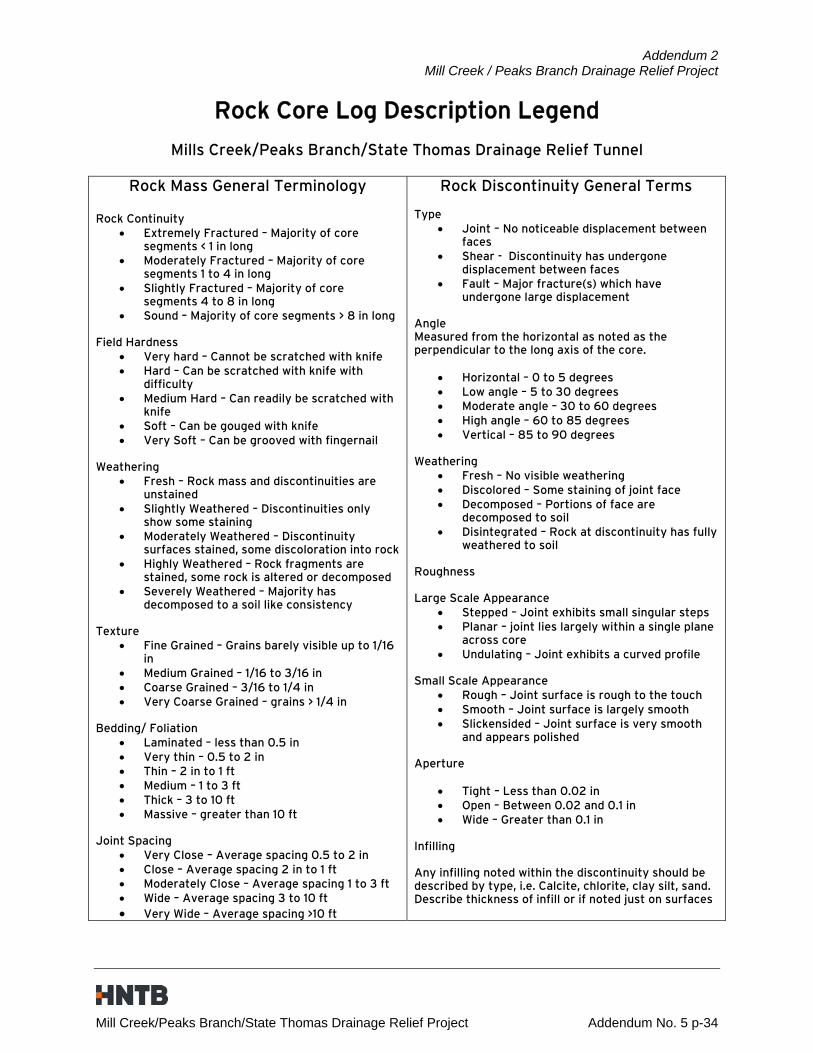
Addendum 2 Mill Creek / Peaks Branch Drainage Relief Project
Rock Core Log Description Legend
Mills Creek/Peaks Branch/State Thomas Drainage Relief Tunnel
Rock Mass General Terminology
Rock Continuity Extremely Fractured – Majority of core
segments < 1 in long Moderately Fractured – Majority of core
segments 1 to 4 in long Slightly Fractured – Majority of core
segments 4 to 8 in long Sound – Majority of core segments > 8 in long
Field Hardness
Very hard – Cannot be scratched with knife Hard – Can be scratched with knife with
difficulty Medium Hard – Can readily be scratched with
knife Soft – Can be gouged with knife Very Soft – Can be grooved with fingernail
Weathering
Fresh – Rock mass and discontinuities are unstained
Slightly Weathered – Discontinuities only show some staining
Moderately Weathered – Discontinuity surfaces stained, some discoloration into rock
Highly Weathered – Rock fragments are stained, some rock is altered or decomposed
Severely Weathered – Majority has decomposed to a soil like consistency
Texture
Fine Grained – Grains barely visible up to 1/16 in
Medium Grained – 1/16 to 3/16 in Coarse Grained – 3/16 to 1/4 in Very Coarse Grained – grains > 1/4 in
Bedding/ Foliation
Laminated – less than 0.5 in Very thin – 0.5 to 2 in Thin – 2 in to 1 ft Medium – 1 to 3 ft Thick – 3 to 10 ft Massive – greater than 10 ft
Joint Spacing
Very Close – Average spacing 0.5 to 2 in Close – Average spacing 2 in to 1 ft Moderately Close – Average spacing 1 to 3 ft Wide – Average spacing 3 to 10 ft Very Wide – Average spacing >10 ft
Rock Discontinuity General Terms Type
Joint – No noticeable displacement between faces
Shear - Discontinuity has undergone displacement between faces
Fault – Major fracture(s) which have undergone large displacement
Angle Measured from the horizontal as noted as the perpendicular to the long axis of the core.
Horizontal – 0 to 5 degrees Low angle – 5 to 30 degrees Moderate angle – 30 to 60 degrees High angle – 60 to 85 degrees Vertical – 85 to 90 degrees
Weathering
Fresh – No visible weathering Discolored – Some staining of joint face Decomposed – Portions of face are
decomposed to soil Disintegrated – Rock at discontinuity has fully
weathered to soil Roughness Large Scale Appearance
Stepped – Joint exhibits small singular steps Planar – joint lies largely within a single plane
across core Undulating – Joint exhibits a curved profile
Small Scale Appearance
Rough – Joint surface is rough to the touch Smooth – Joint surface is largely smooth Slickensided – Joint surface is very smooth
and appears polished Aperture
Tight – Less than 0.02 in Open – Between 0.02 and 0.1 in Wide – Greater than 0.1 in
Infilling Any infilling noted within the discontinuity should be described by type, i.e. Calcite, chlorite, clay silt, sand. Describe thickness of infill or if noted just on surfaces
Mill Creek/Peaks Branch/State Thomas Drainage Relief Project Addendum No. 5 p-34

87010
BOGUMIL NOSEK
TBPE FIRM #F-312
HALFF ASSOCIATES, INC.
TRINITY WATERSHED MANAGEMENT
CITY OF DALLAS, TEXAS
NO.FILESCALEDRAWNDESIGN
SC
ALE:
PE
NT
AB
LE.T
BL
1:12
0
PE
NT
AB
LE:
11:1
3:5
2
AM
TIM
E:
DA
TE:
12/7/2015
PD
F_2
D_
MO
N_
HW
_M
R_300.plt
PL
OT
DRIV
ER:
ah2823
US
ER:
FIL
E
NA
ME:...\C
AD
D\Sheets\25299-C
O-2
01.dgn
DATENO. REVISION DESCRIPTION
TBPE REGISTRATION NO. 312
12225 GREENVILLE AVE., SUITE 200 DALLAS, TEXAS 75243 (214) 346-6200 (TEL)
DATE NOTES
25299
AVO
DRAINAGE RELIEF PROJECT
MILL CREEK/PEAKS BRANCH/STATE THOMAS
421Q57802015
OCT
S
SS
S
S
S
S
S
S
S
S
S
S
S
S
S
SS
S
S
S
S
S
S
BARBER AVE.
CR
EE
KW
HIT
E
RO
CK
DIX
ON
AV
E.
SCYE
NE RD.
STATE
HIG
HW
AY
352
MU
RA
L L
AN
E
0
HORIZONTAL SCALE IN FEET
N
HALFF AS NOTEDHALFF
SITE O
30 60 90 120
CONSTRUCTION SITE
REQUIREMENTS
CR
EE
KW
HIT
E
RO
CK
R.O.W.
ONCOR
5 12-7-2015 ADD. No. 5 - ADDITIONAL AREA
5
5
5
CO-201
504
216
COD
CODCOD
COD
COD
COD
COD
101102
901
901900
900
100
149903
151
152
902
153145a
144
145b
143
142
141
140
103
146
147 148
154
150
145c
CODCOD
COD
COD
COD
ITEMS REQUIRED BY THE OWNER'S REPRESENTATIVE.
CONSTRUCTION SITE GRADING MODIFICATIONS, AND OTHER
FENCE, GATES, ACOUSTICAL WALLS AND HEIGHTS,
STORAGE AREAS, MAJOR EQUIPMENT LOCATIONS, SECURITY
AVENUE, INTERNAL DRIVES, PARKING AREAS, STOCKPILE AND
FOLLOWING ITEMS: CONSTRUCTION ENTRANCES FROM BARBER
CONSTRUCTION SITE LAYOUT PLAN(S) SHALL INCLUDE THE
LAYOUT PLAN(S) FOR REVIEW AND APPROVAL. THE
THE CONTRACTOR SHALL SUBMIT A CONSTRUCTION SITE
LOOPED DRIVE FOR EMERGENCY ACCESS.
AREAS WITHIN A 100-FOOT (MINIMUM) RADIUS OF THE CENTER OF THE TUNNEL OUTFALL SHAFT, AND THE
THE CONSTRUCTION SITE SHALL BE RAISED TO A MINIMUM ELEVATION OF 407 FEET. THIS INCLUDES ALL
FEET, MINIMUM, ABOVE THE 100-YEAR FLOOD ELEVATION.
SWITCHES, CONSTRUCTION TRAILERS, AND PERMENANT MATERIALS SHALL BE STORED AT AN ELEVATION OF 2
EQUIPMENT DURING CONSTRUCTION. FIXED EQUIPMENT, ELECTRICAL EQUIPMENT SUCH AS TRANSFORMERS AND
THE CONTRACTOR SHALL SUBMIT A FLOOD EMERGENCY PLAN TO PROTECT THE UNDERGROUND TUNNEL AND
RATE MAP (FIRM) NUMBER 48113CO365J, DATED AUGUST 23, 2011.
THE 100-YEAR WATER SURFACE ELEVATION FOR WHITE ROCK CREEK IS 406.7 FEET PER FLOOD INSURANCE
SITE IMPROVEMENTS ARE SUBSIDIARY TO THE REMAINDER OF THE WORK ITEMS IN THIS CONTRACT.
GRADING IMPROVEMENTS ARE PROVIDED FOR UNDER BID ITEMS 102E AND 102F. ALL OTHER CONSTRUCTION
LOCATIONS TO FORM A LOOP, AND SHALL ACCOMMODATE AMBULANCE AND FIRE TRUCK TURNING MOVEMENTS.
EMERGENCY VEHICLES SUCH AS AMBULANCES AND FIRE TRUCKS, SHALL CONNECT AT BARBER AVENUE AT TWO
OUTFALL SHAFT, SHALL BE CONSTRUCTED OF AN ALL-WEATHER MATERIAL CAPABLE OF SUPPORTING
DALLAS, FIRE/RESCUE DEPARTMENT. THE CONTINOUS DRIVE SHALL BE A MAXIMUM OF 50 FEET FROM THE
TUNNEL OUTFALL SHAFT TO ACCOMMODATE EMERGENCY ACCESS TO THE OUTFALL SHAFT BY THE CITY OF
THE CONTRACTOR SHALL PROVIDE A 24-FOOT WIDE (MINIMUM) LOOPED DRIVE FROM BARBER AVENUE TO THE
13.
12.
11.
10.
9.
8.
7.
TRESPASS BEYOND THE LIMITS OF THE CONSTRUCTION SITE.
SIGHT LIGHTING SHALL BE DIRECTED AND SHIELDED AS NECESSARY TO PREVENT LIGHT
REFER TO DEMOLITION PLAN SHEETS FOR PROPERTY INFORMATION.
LIKELY TO DAMAGE THE REMAINING WETLAND.
STUMPS AND/OR ROOT SYSTEMS ARE PROHIBITED IN AREAS WHERE THE REMOVAL IS
JURISDICTIONAL WETLANDS SHALL REMAIN IN THE GROUND. OPERATIONS TO REMOVE
STUMPS AND ROOT SYSTEMS ADJACENT, OR IN CLOSE PROXIMITY, TO REMAINING
A MANNER THAT PRESERVES (DOES NOT DAMAGE) THE SOIL PROFILE.
SECURITY FENCES, IN THE REMAINING JURISDICTIONAL WETLANDS SHALL BE PERFORMED IN
MAINTENANCE TYPE ACTIVITIES, SUCH AS LIGHT MOWING ADJACENT TO PERIMETER
OTHERWISE DAMAGE THE GROUND.
JURISDICTIONAL WETLANDS SHALL BE LIMITED TO SMALL VEHICLES THAT DO NOT RUT OR
WETLANDS WHEN THE GROUND IS SUFFICIENTLY DRY TO AVOID RUTTING. EQUIPMENT IN
SURFACE SOILS ARE WET. OPERATIONS ARE ONLY PERMITTED IN JURISDICTIONAL
OPERATIONS IN THE REMAINING JURISDICTIONAL WETLANDS ARE PROHIBITED WHEN THE
CO-103 AND CO-104.
LIMITS OF JURISDICTIONAL WETLANDS DESIGNATED AS "IMPACTED" ON CO-101, CO-102,
CONTRACTOR MAY PLACE FILL MATERIAL AND PERFORM OTHER OPERATIONS WITHIN THE
WETLANDS.
REPRESENTATIVE MUST BE PRESENT WHEN PERFORMING ANY ACTIVITY IN JURISDICTIONAL
PRIOR TO PERFORMING ANY ACTIVITIES WITHIN JURISDICTIONAL WETLANDS. THE OWNER'S
CONTRACTOR SHALL CONTACT THE OWNER'S REPRESENTATIVE A MINIMUM OF 48 HOURS
6.
5.
4.
3.
2.
1.
NOTES:
~
14.
ASSOCIATED WITH THE UTILIZATION OF THESE AREAS.
PAYMENT SHALL BE MADE TO THE CONTRACTOR FOR WORK
RESTORE THE AREAS UPON PROJECT COMPLETION. NO SEPARATE
FENCING, AND EROSION CONTROL MEASURES. CONTRACTOR SHALL
GRUBBING, GRADING, IMPORTING MATERIALS, PAVING, LIGHTING,
DURING CONSTRUCTION INCLUDING, BUT NOT LIMITED TO, CLEARING,
ALL WORK NECESSARY TO PREPARE THESE AREAS FOR USE
DURING CONSTRUCTION. THE CONTRACTOR IS RESPONSIBLE FOR
THE HATCHED AREAS MAY BE UTILIZED BY THE CONTRACTOR
SECURE SITE
GATE REQUIRED TO
SOUTHWEST BOUNDARY
SOUND WALL ALONG
TEMPORARY
SECURE SITE
GATE REQUIRED TO
SHAFT
TUNNEL OUTFALL
~
TO REMAIN
TREE BUFFER
20' MIN. EXISTING
TEMPORARY SECURITY FENCE
TEMPORARY SECURITY FENCE
CONSTRUCTION OPERATIONS.
ELEV. OF 407 DURING TUNNEL
CONSTRUCTION SITE TO A MIN.
CONTRACTOR SHALL RAISE THE
TO REMAIN
WETLAND
JURISDICTIONAL
WETLAND TO REMAIN
JURISDICTIONAL
BARRIER ALONG NORTHWEST BOUNDARY
TEMPORARY SOUND WALL/SECURITY
DEMOLITION PLAN SHEETS.
LIMITS DEPICTED ON SITE O
CLEARING AND GRUBBING
OPERATIONS BEYOND
EXPAND SITE CONSTRUCTION
CONTRACTOR SHALL NOT
SEPARATE CONTRACT
DEMOLISHED BY
STRUCTURE TO BE
CONSTRUCTION (TYP.)
CONTRACTOR DURING
IS AVAILABLE TO
THE HATCHED AREA
35
Mill Creek/Peaks Branch/State Thomas Drainage Relief Project Addendum No. 5 p-35

HALFF AS NOTEDHALFF
3 11-16-2015 ADD. No. 3 - NEW SHEET
ESTIMATED PROJECT QUANTITIES
BID ALTERNATE No. 4
5 12-7-2015 ADD. No. 5 - REVISE ITEM & QUANTITY
TRINITY WATERSHED MANAGEMENT
CITY OF DALLAS, TEXAS
NO.FILESCALEDRAWNDESIGN
SC
ALE:
HA
LF
F_
MO
N_P
EN
TA
BLE.T
BL
1:2
PE
NT
AB
LE:
1:0
3:4
1 P
MTIM
E:
DA
TE:
12/8/2015
PD
F_2
D_
MO
N_
HW
_M
R_300.plt
PL
OT
DRIV
ER:
ah2823
US
ER:
FIL
E
NA
ME:...\25299-A
4C
N-0
01.dgn
DATENO. REVISION DESCRIPTION
TBPE REGISTRATION NO. 312
12225 GREENVILLE AVE., SUITE 200 DALLAS, TEXAS 75243 (214) 346-6200 (TEL)
DATE NOTES
25299
AVO
DRAINAGE RELIEF PROJECT
MILL CREEK/PEAKS BRANCH/STATE THOMAS
421Q 57802015
OCT
HALFF ASSOCIATES, INC.
TBPE REGISTRATION NO. 312
87010
PE# Date
BOGUMIL NOSEK
PRELIMINARY - FOR BIDDING PURPOSES ONLY
prepared by, or under the supervision of:for Construction or Permit Purposes. They wereThese documents are for Interim Review and not intended
DECEMBER 7, 2015
BID ALTERNATE No. 4
ADDENDUM No. 5 CHANGES:
5
CHANGED PLAN AND BID QUANTITIES: 4009B
DELETED ITEM: 4009C
ITEM DESCRIPTIONITEM UNIT
NO.SHEET
QTY.PLAN
TOTAL
QTY.BID
TOTAL
NO. A4CD-206 A4CD-306 MISC
102 Excavation StreetUnclassified CY - - - - 1,000
423 Wall Ret 6 Type ConcreteReinforced CY - 0.6 - 1 5
424Y Wall Retaining VeneerStone CY - 33 - 33 50
636 Hydromulching by SeedingGrass SY 1,103 - - 1,103 1,160
645 Fence SiltGeotextile LF 375 - - 375 380
1008 Pipe Concrete Reinforced III Class36" LF - 278 - 278 280
1014 Pipe Concrete Reinforced III Class54" LF - 35 - 35 40
1201Z Wall Integral with Inlet10' EA - 15 - 15 15
1225A ProtectionInlet EA 15 - - 15 15
1350 Mattress Block ConcreteArticulated SF 6,205 - - 6,205 6,300
1418 Support and Safety ExcavationTrench LF - 463 - 463 470
1650 (Storm) InspectionTelevision LF - 463 - 463 470
1977 Box Concrete Reinforced9'x9' LF - 150 - 150 150
4009B VeneerStone SF - 1,320 - 1,320 1,400
A4CN-001
36
Mill Creek/Peaks Branch/State Thomas Drainage Relief Project Addendum No. 5 p-36

TRINITY WATERSHED MANAGEMENT
CITY OF DALLAS, TEXAS
NO.FILESCALEDRAWNDESIGN
SC
ALE:
PE
NT
AB
LE.T
BL
1:39.9
999
PE
NT
AB
LE:
1:0
8:2
9 P
MTIM
E:
DA
TE:
12/8/2015
PD
F_2
D_
MO
N_
HW
_M
R_300.plt
PL
OT
DRIV
ER:
ah2823
US
ER:
FIL
E
NA
ME:...\25299-A
4C
D-3
06.d
gn
DATENO. REVISION DESCRIPTION
TBPE REGISTRATION NO. 312
12225 GREENVILLE AVE., SUITE 200 DALLAS, TEXAS 75243 (214) 346-6200 (TEL)
DATE NOTES
25299
AVO
DRAINAGE RELIEF PROJECT
MILL CREEK/PEAKS BRANCH/STATE THOMAS
421Q57802015
OCT
LEGEND:
XXX
COMMENCING WORK.
VICINITY OF CONSTRUCTION PRIOR TO
ALL UNDERGROUND UTILITIES IN THE
HORIZONTAL AND VERTICAL LOCATIONS OF
IN VICINITY. CONTRACTOR SHALL VERIFY
UNDERGROUND AND OVERHEAD UTILITIES
CAUTION!!!
SHEETS FOR KNOWN EXISTING UTILITIES.
CLARITY ON THIS DRAWING. REFER TO DEMOLITION
NOT ALL EXISTING UTILITIES ARE SHOWN FOR
PROPERTY INFORMATION.
REFER TO DEMOLITION PLAN SHEETS FOR
UNLESS OTHERWISE NOTED.
ALL REINFORCED CONCRETE PIPE SHALL BE CLASS III
OTHERWISE NOTED.
ALL LATERAL CONNECTIONS ARE 60° UNLESS
4.
3.
2.
1.
NOTES:
HG
=477.0
7
HG
=477.7
3
HG
=477.9
7
FL 9'x
9'
= 466.8
6
FL 9'x
9'
= 466.9
8
2
f
CAP
100
2
f
CAP
100
EXISTING GRADE
HGL
SD LINE D1
CALCULATIONS.
THRU CD-310 FOR HYDRAULIC
CONDITIONS. REFER TO SHEETS CD-308
SHOWN ARE BASED ON INTERIM
STORM DRAINAGE CALCULATIONS
2g
V = 0.85 ft
S = 0.0014 ft/ft
V = 7.41 fps
Q = 710.99 cfs
Q = 600 CFS
RT CURB JUNIUS
PROP. GRADE
2g
V = 2.14 ft
S = 0.0036 ft/ft
V = 11.73 fps
Q = 710.99 cfs
Q = 950 CFS
ST
A 18
+15
9'x9' PRECAST RCB ON 0.20% 284 LF OF
CO
NN
EC
T 24"
RC
P
ST
A 0
+00
LA
T
D1a
FL 72"
= 468.9
0
FL 9'x
9'
= 466.9
0
CO
NN
EC
T 72"
RC
P
ST
A 0
+00
LA
T
D1b
ST
A 17
+74
=H
G=477.1
0
HG
=477.6
8
9'x9' RCB ON 0.20%
HG
=478.8
3
9'x
9'
RC
B
EN
D
AN
D
PL
UG
ST
A 19
+63.9
3
2
f
CAP
100
2g
V = 0.61 ft
S = 0.0009 ft/ft
V = 6.25 fps
Q = 879.70 cfs
Q = 600 CFS
MH
RIM
EL
EV.
= 481.5
7
ST
RU
CT
UR
E
D1B
JU
NC
TIO
N
9'x
9'
= 467.2
7
CM
32" TREE 24" TREE
6" TREE
36" TREE
19" TREE
7" TREE
36" PECAN
17" TREE
8' CHAIN LINK FENCE
5' W
IRE
FE
NC
E
6' W
OO
D
FE
NC
E
ICVICVICVICVICVICV
BH
MAP 35-2
8 (B
uilt
Unknown)
EX 10
" W
W
4" CAST IRON LP GAS
421-245 (B
uilt 1923)
EX 78" CONC ST
M SE
WE
R
VICTOR ST.
CARROLL AVE. AND 18.5' FROM NORTH CURB OF
SET "X" ON CURB INLET 4' FROM THE WEST CURB OF
CARROLL AVE.
CORNER OF THE INTERSECTION OF WORTH ST. AND
SET "X" ON SIDEWALK 7.3' FROM CURB AT SOUTHWEST
INTERSECTION WITH VICTOR ST.
CARROLL AVE. AND 188' NORTH FROM THE
SET ROD TO REFUSAL 8' BEHIND THE EAST CURB OF
ELEV = 473.62 N. 6976991.52 E. 2500417.47
CONTROL POINT #94
ELEV = 479.54 N. 6977457.37 E. 2499920.29
CONTROL POINT #84
ELEV = 474.58 N. 6977182.57 E. 2500282.50
BENCHMARK #RR4
HALFF ASSOCIATES, INC.
TBPE REGISTRATION NO. 312
87010
PE# Date
BOGUMIL NOSEK
PRELIMINARY - FOR BIDDING PURPOSES ONLY
prepared by, or under the supervision of:for Construction or Permit Purposes. They wereThese documents are for Interim Review and not intended
DECEMBER 7, 2015
16+00 17+00 18+00LINE D1 9'x9' PRECAST RCB
19
+00
LIN
E
D1 9'x
9'
RC
B
0
HORIZONTAL SCALE IN FEET
N
10 20 30 40
0
VERTICAL SCALE IN FEET
3 6 9 12
JUNIUS STREET
SITE D - DRAINAGE
3 11-16-2015 ADD. No. 3 - NEW SHEET
BID ALTERNATE No. 4
REF. SHT A4SD-702 FOR DETAILS
LATERAL PENETRATIONS NOT SHOWN
1201Z
4009B
424Y
1977
1418
14' CURB INLET
14' CURB INLET
SPECIAL "Y" INLET
SPECIAL "Y" INLET
SPECIAL "Y" INLET
SPECIAL "Y" INLET
SPECIAL "Y" INLET
SPECIAL "Y" INLET
SPECIAL "Y" INLET
SPECIAL "Y" INLET
DESCRIPTION
8'R
20'R2
0'
R
11'R
1008
1014
1008
E=2,499,999.95
N=6,978,102.35
E=2,500,005.54
N=6,978,091.98E=2,499,960.04
N=6,978,058.15
E=2,499,969.18
N=6,978,058.12
E=2,499,994.28
N=6,978,052.14
E=2,499,999.49
N=6,978,049.23
E=2,500,008.75
N=6,978,040.00
E=2,500,011.99
N=6,978,032.29
11'
R
E=2,500,012.21
N=6,978,003.59
E=2,500,014.60
N=6,977,997.95
4009B
423
423
(1,320 SF - SHEET TOTAL)
STONE VENEER
(33 CY - SHEET TOTAL)
STONE VENEER RETAINING WALL
TO DETAIL 05 ON SHEET MD-401
STONE VENEER RETAINING WALL. REFER
5 12-7-2015 ADD. No. 5 - STONE VENEER & CAP QUANTITY
5
5
CONSTRUCT STORM DRAIN SYSTEM
INLET NUMBER
A4CD-306
495
490
485
480
475
470
465
460
455
500
470
465
460
455
495
490
485
475
480
500
17+00 17+50 18+00 18+5015+50 16+00 16+50
JUNIUS ST
19+00 19+50 20+00
TO 54" RCP (TYP.)
36" LATERAL CONNECTION
E=2,499,998.91
N=6,978,107.58
END WALL AT SIDEWALK
E=2,499,946.54
N=6,978,055.03
END WALL AT SIDEWALK
INCIDENTAL-NO SEPARATE PAYMENT)
INCLUDING INTEGRAL SIDEWALK. (SIDEWALK IS
7 LF OF TYPE 6 RETAINING WALL PER 251D-1 PG 3003
INCIDENTAL-NO SEPARATE PAYMENT)
INCLUDING INTEGRAL 6" SIDEWALK. (SIDEWALK IS
7 LF OF TYPE 6 RETAINING WALL PER 251D-1 PG 3003
E= 2,500,056.31
N= 6,977,955.96
BACK OF WALL PI
E= 2,500,099.80
N= 6,978,000.14
BACK OF WALL PI
A4SD-702
PER DETAILS ON
1' BELOW RCB SOFFIT
TO 9'x9' RCB AT 60° AT
54" LATERAL CONNECTION
E= 2,500,058.11
N= 6,978,041.18
10' INLET WITH INTEGRAL WALL
END RETAINING WALL. BEGIN E= 2,500,014.62
N= 6,977,996.99
BEGIN RETAINING WALL.
END 10' INLET WITH INTEGRAL WALL.
E= 2,500,073.54
N= 6,977,988.11
END LINE D1 9'x9' RCB
A4SD-702 (TYP.)
9'x9' RCB PER DETAILS ON
36" LATERAL CONNECTING TO
E= 2,499,967.87
N= 6,978,093.43
D1b WILL NOT BE ADJUSTED FOR ALTERNATE 4 CONSTRUCTION.
BE CONNECTED. BASE BID UNIT PRICE OF JUNCTION STRUCTURE
STRUCTURE WILL NOT BE CONSTRUCTED AND 9'x9' BOX WILL
IF ALTERNATE 4 IS ELECTED, SOUTHEAST WALL OF JUNCTION
ITEM FOR THIS JUNCTION STRUCTURE IS INCLUDED IN BASE BID.
REFER TO SHEETS A4SD-301 & A4SD-302 FOR DETAILS. BID
INSTALL JUNCTION STRUCTURE D1b
STA 18+15 LINE D1
ROW
ROW
(15 EA-SHEET TOTAL)
VENEER. REF TO SHT. MD-201A
RETAINING WALL WITH STONE
10' CURB INLET WITH INTEGRAL
37
Mill Creek/Peaks Branch/State Thomas Drainage Relief Project Addendum No. 5 p-37