actuators
TRANSCRIPT

USER GUIDE for the study of
ACTUATORS
Made by:
Ramana Krishnan
B.Tech - MPAE
NSIT
Swati Bansal
Btech Computer Science Engg.
Delhi College of Engineering
PPPLLLCCC IIINNNSSSTTTIIITTTUUUTTTEEE OOOFFF EEELLLEEECCCTTTRRROOONNNIIICCCSSSwwwwwwwww...ppplllccciiieee...cccooommm eeemmmaaaiiilll iiiddd ––– ppplllccciiieee@@@rrreeedddiiiffffffmmmaaaiiilll...cccooommm ppphhh nnnooo...::: 999333111222222555666444111555///999888999999888999333000888000

This tutorial assumes certain basic knowledge of DC motors. This tutorial should be used
as a reference material and not as a primary source of study. This tutorial attempts to give
the reader a brief peek into the world of actuators…
Speed control of DC motor through PWM
One of the most fundamental problems in robotics is DC motor speed control. The most
common method of speed control is PWM or pulse width modulation. Pulse width
modulation is the process of switching the power to a device on and off at a given
frequency, with varying on and off times. These on and off times are referred to as "duty
cycle". The diagram below shows the waveforms of 10%, 50%, and 90% duty cycle
signals.
As you can see from the diagram, a 10% duty cycle signal is on for 10% of the
wavelength and off for 90%, while a 90% duty cycle signal is on for 90% and off for
10%. These signals are sent to the motor at a high enough frequency that the pulsing has
no effect on the motor. The end result of the PWM process is that the overall power sent
to the motor can be adjusted from off (0% duty cycle) to full on (100% duty cycle) with
good efficiency and stable control.
While many robot builders use a microcontroller to generate the required PWM signals,
the 555 PWM circuit explained here will give the novice robot builder an easy to
construct circuit, and good understanding of pulse width modulation. It is also useful in a
variety of other applications where the PWM setting need only be changed occasionally.
PPPLLLCCC IIINNNSSSTTTIIITTTUUUTTTEEE OOOFFF EEELLLEEECCCTTTRRROOONNNIIICCCSSSwwwwwwwww...ppplllccciiieee...cccooommm eeemmmaaaiiilll iiiddd ––– ppplllccciiieee@@@rrreeedddiiiffffffmmmaaaiiilll...cccooommm ppphhh nnnooo...::: 999333111222222555666444111555///999888999999888999333000888000

The 555 timer in the PWM circuit is configured as an astable oscillator. This means that
once power is applied, the 555 will oscillate without any external trigger. Before the
technical explanation of the circuit, let's look at the 555 timer IC itself.
A block diagram of the 555 timer:
PPPLLLCCC IIINNNSSSTTTIIITTTUUUTTTEEE OOOFFF EEELLLEEECCCTTTRRROOONNNIIICCCSSSwwwwwwwww...ppplllccciiieee...cccooommm eeemmmaaaiiilll iiiddd ––– ppplllccciiieee@@@rrreeedddiiiffffffmmmaaaiiilll...cccooommm ppphhh nnnooo...::: 999333111222222555666444111555///999888999999888999333000888000

Pin descriptions for the 555
PIN DESCRIPTION PURPOSE
1 Ground DC Ground
2 Trigger
The trigger pin triggers the beginning of the timing
sequence. When it goes LOW, it causes the output pin
to go HIGH. The trigger is activated when the voltage
falls below 1/3 of +V on pin 8.
3 Output
The output pin is used to drive external circuitry. It
has a "totem pole" configuration, which means that it
can source or sink current. The HIGH output is
usually about 1.7 volts lower than +V when sourcing
current. The output pin can sink up to 200mA of
current. The output pin is driven HIGH when the
trigger pin is taken LOW. The output pin is driven
LOW when the threshold pin is taken HIGH, or the
reset pin is taken LOW.
4 Reset
The reset pin is used to drive the output LOW,
regardless of the state of the circuit. When not used,
the reset pin should be tied to +V.
5 Control Voltage
The control voltage pin allows the input of external
voltages to affect the timing of the 555 chip. When
not used, it should be bypassed to ground through a
0.01uF capacitor.
6 ThresholdThe threshold pin causes the output to be driven LOW
when its voltage rises above 2/3 of +V.
7 Discharge
The discharge pin shorts to ground when the output
pin goes HIGH. This is normally used to discharge the
timing capacitor during oscillation.
8 +V DC Power? Apply +3 to +18VDC here.
PPPLLLCCC IIINNNSSSTTTIIITTTUUUTTTEEE OOOFFF EEELLLEEECCCTTTRRROOONNNIIICCCSSSwwwwwwwww...ppplllccciiieee...cccooommm eeemmmaaaiiilll iiiddd ––– ppplllccciiieee@@@rrreeedddiiiffffffmmmaaaiiilll...cccooommm ppphhh nnnooo...::: 999333111222222555666444111555///999888999999888999333000888000

The schematic diagram for the 555 PWM Circuit:
The reset pin is connected to +V, so it has no effect on the circuit's operation.
When the circuit powers up, the trigger pin is LOW as capacitor C1 is discharged. This
begins the oscillator cycle, causing the output to go HIGH.
When the output goes HIGH, capacitor C1 begins to charge through the right side of R1
and diode D2. When the voltage on C1 reaches 2/3 of +V, the threshold (pin 6) is
activated, which in turn causes the output (pin 3), and discharge (pin 7) to go LOW.
When the output (pin 3) goes LOW, capacitor C1 starts to discharge through the left side
of R1 and D1. When the voltage on C1 falls below 1/3 of +V, the output (pin 3) and
discharge (pin 7) pins go HIGH, and the cycle repeats.
Pin 5 is not used for external voltage input, so it is bypassed to ground with a 0.01uF
capacitor.
Note the configuration of R1, D1, and D2. Capacitor C1 charges through one side of R1
and discharges through the other side. The sum of the charge and discharge resistance is
always the same; therefore the wavelength of the output signal is constant. Only the duty
cycle varies with R1.
The overall frequency of the PWM signal in this circuit is determined by the values of R1
and C1. In the schematic above, this has been set to 144 Hz.
PPPLLLCCC IIINNNSSSTTTIIITTTUUUTTTEEE OOOFFF EEELLLEEECCCTTTRRROOONNNIIICCCSSSwwwwwwwww...ppplllccciiieee...cccooommm eeemmmaaaiiilll iiiddd ––– ppplllccciiieee@@@rrreeedddiiiffffffmmmaaaiiilll...cccooommm ppphhh nnnooo...::: 999333111222222555666444111555///999888999999888999333000888000

To compute the component values for other frequencies, use the formula:
Frequency = 1.44 / (R1 * C1)
In this circuit, the output pin is used to charge and discharge C1, rather than the discharge
pin. This is done because the output pin has a "totem pole" configuration. It can source
and sink current, while the discharge pin only sinks current. Note that the output and
discharge pins go HIGH and LOW at the same time in the oscillator cycle.
The discharge pin is used to drive the output. In this case, the output is an IRFZ46N
MOSFET. The gate of the MOSFET must be pulled high, as the discharge pin is open
collector only. Being an N channel MOSFET, the IRFZ46N will conduct from drain to
source when the gate pin rises above 4 volts or so. It will stop conducting when the gate
voltage falls below this voltage. The configuration of the output also serves to invert the
signal from the 555 circuit.
PPPLLLCCC IIINNNSSSTTTIIITTTUUUTTTEEE OOOFFF EEELLLEEECCCTTTRRROOONNNIIICCCSSSwwwwwwwww...ppplllccciiieee...cccooommm eeemmmaaaiiilll iiiddd ––– ppplllccciiieee@@@rrreeedddiiiffffffmmmaaaiiilll...cccooommm ppphhh nnnooo...::: 999333111222222555666444111555///999888999999888999333000888000

H-BRIDGE
1. Motor Supply (+12V / +24V)
2. Logic Supply (+5V)
3. Clockwise (Active Low)
4. Counter-Clockwise (Active Low)
5. Ground
6. Points to be soldered with DC motor
7. Power Transistor
8. Opto-Coupler Device to provide isolation
1 2 4 53
6
7
8
PPPLLLCCC IIINNNSSSTTTIIITTTUUUTTTEEE OOOFFF EEELLLEEECCCTTTRRROOONNNIIICCCSSSwwwwwwwww...ppplllccciiieee...cccooommm eeemmmaaaiiilll iiiddd ––– ppplllccciiieee@@@rrreeedddiiiffffffmmmaaaiiilll...cccooommm ppphhh nnnooo...::: 999333111222222555666444111555///999888999999888999333000888000


What's all this talk about H-Bridges? How do they work? Well let's see . . .
How do we make a motor turn?
You take a battery; hook the positive side to one side of your DC motor. Then you
connect the negative side of the battery to the other motor lead. The motor spins forward.
If you swap the battery leads the motor spins in reverse.
Ok, that's basic. Now let’s say you want a Micro Controller Unit (MCU) to control the
motor, how would you do it? Well, for starters you get a device that would act like a solid
state switch, a transistor, and hook it up the motor.
NOTE: If you connect up these relay circuits, remember to put a diode across the coil of
the relay. This will keep the spike voltage (back EMF), coming out of the coil of the
relay, from getting into the MCU and damaging it. The anode, which is the arrow side of
the diode, should connect to ground. The bar, which is the Cathode side of the diode,
should connect to the coil where the MCU connects to the relay
If you connect this circuit to a small hobby motor you can control the motor with a
processor (MCU, etc.) Applying a logical one, (+12 Volts in our example) to point A
causes the motor to turn forward. Applying a logical zero, (ground) causes the motor to
stop turning (to coast and stop).
Hook the motor up in this fashion and the circuit turns the motor in reverse when you
apply a logical one (+12Volts) to point B. Apply a logical zero, which is usually a
ground, causes the motor to stop spinning.
If you hook up these circuits you can only get the motor to stop or turn in one direction,
forward for the first circuit or reverse for the second circuit.
PPPLLLCCC IIINNNSSSTTTIIITTTUUUTTTEEE OOOFFF EEELLLEEECCCTTTRRROOONNNIIICCCSSSwwwwwwwww...ppplllccciiieee...cccooommm eeemmmaaaiiilll iiiddd ––– ppplllccciiieee@@@rrreeedddiiiffffffmmmaaaiiilll...cccooommm ppphhh nnnooo...::: 999333111222222555666444111555///999888999999888999333000888000
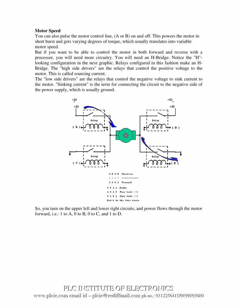
Motor Speed
You can also pulse the motor control line, (A or B) on and off. This powers the motor in
short burst and gets varying degrees of torque, which usually translates into variable
motor speed.
But if you want to be able to control the motor in both forward and reverse with a
processor, you will need more circuitry. You will need an H-Bridge. Notice the "H"-
looking configuration in the next graphic. Relays configured in this fashion make an H-
Bridge. The "high side drivers" are the relays that control the positive voltage to the
motor. This is called sourcing current.
The "low side drivers" are the relays that control the negative voltage to sink current to
the motor. "Sinking current" is the term for connecting the circuit to the negative side of
the power supply, which is usually ground.
So, you turn on the upper left and lower right circuits, and power flows through the motor
forward, i.e.: 1 to A, 0 to B, 0 to C, and 1 to D.
PPPLLLCCC IIINNNSSSTTTIIITTTUUUTTTEEE OOOFFF EEELLLEEECCCTTTRRROOONNNIIICCCSSSwwwwwwwww...ppplllccciiieee...cccooommm eeemmmaaaiiilll iiiddd ––– ppplllccciiieee@@@rrreeedddiiiffffffmmmaaaiiilll...cccooommm ppphhh nnnooo...::: 999333111222222555666444111555///999888999999888999333000888000

Then for reverse you turn on the upper right and lower left circuits and power flows
through the motor in reverse, i.e.: 0 to A, 1 to B, 1 to C, and 0 to D.
CAUTION: You should be careful not to turn on both circuits on one side or the other,
or you have a direct short which will destroy your circuit; Example: A and C or B and D
both high (logical 1).
Semiconductor H-Bridges
We can better control our motor by using transistors or Field Effect Transistors (FETs).
Most of what we have discussed about the relays H-Bridge is true of these circuits. You
don't need diodes that were across the relay coils now. You should use diodes across your
transistors though. See the following diagram showing how they are connected.
These solid state circuits provide power and ground connections to the motor, as did the
relay circuits. The high side drivers need to be current "sources" which is what PNP
transistors and P-channel FETs are good at. The low side drivers need to be current
"sinks" which is what NPN transistors and N-channel FETs are good at.
PPPLLLCCC IIINNNSSSTTTIIITTTUUUTTTEEE OOOFFF EEELLLEEECCCTTTRRROOONNNIIICCCSSSwwwwwwwww...ppplllccciiieee...cccooommm eeemmmaaaiiilll iiiddd ––– ppplllccciiieee@@@rrreeedddiiiffffffmmmaaaiiilll...cccooommm ppphhh nnnooo...::: 999333111222222555666444111555///999888999999888999333000888000

If you turn on the two upper circuits, the motor resists turning, so you effectively have a
breaking mechanism. The same is true if you turn on both of the lower circuits. This is
because the motor is a generator and when it turns it generates a voltage. If the terminals
of the motor are connected (shorted), then the voltage generated counteracts the motor’s
freedom to turn. It is as if you are applying a similar but opposite voltage to the one
generated by the motor being turned. Vis-à-vis, it acts like a brake.
To be nice to your transistors, you should add diodes to catch the back voltage that is
generated by the motor's coil when the power is switched on and off. This flyback
voltage can be many times higher than the supply voltage! If you don't use diodes, you
could burn out your transistors.
PPPLLLCCC IIINNNSSSTTTIIITTTUUUTTTEEE OOOFFF EEELLLEEECCCTTTRRROOONNNIIICCCSSSwwwwwwwww...ppplllccciiieee...cccooommm eeemmmaaaiiilll iiiddd ––– ppplllccciiieee@@@rrreeedddiiiffffffmmmaaaiiilll...cccooommm ppphhh nnnooo...::: 999333111222222555666444111555///999888999999888999333000888000

Transistors, being a semiconductor device, will have some resistance, which causes them
to get hot when conducting much current. This is called not being able to sink or source
very much power, i.e.: Not able to provide much current from ground or from plus
voltage.
Mosfets are much more efficient; they can provide much more current and not get as hot.
They usually have the flyback diodes built in so you don't need the diodes anymore. This
helps guard against flyback voltage frying your MCU.
To use Mosfets in an H-Bridge, you need P-Channel Mosfets on top because they can
"source" power and N-Channel Mosfets on the bottom because then can "sink" power. N-
Channel Mosfets are much cheaper than P-Channel Mosfets, but N-Channel Mosfets used
to source power require about 7 volts more than the supply voltage, to turn on. As a
result, some people manage to use N-Channel Mosfets, on top of the H-Bridge, by using
cleaver circuits to overcome the breakdown voltage.
It is important that the four quadrants of the H-Bridge circuits be turned on and off
properly. When there is a path between the positive and groundside of the H-Bridge,
other than through the motor, a condition exists called "shoot through". This is basically a
direct short of the power supply and can cause semiconductors to become ballistic, in
circuits with large currents flowing. There are H-bridge chips available that are much
easier, and safer, to use than designing your own H-Bridge circuit.
H-Bridge Devices
The L 293 has 2 H-Bridges, can provide about 1 amp to each and occasional peak loads
to 2 amps. Motors typically controlled with this controller are near the size of a 35 mm
film plastic canister.
The L298 has 2 h-bridges on board, can handle 1amp and peak current draws to about
3amps. You often see motors between the size of 35 mm film plastic canister and a coke
can, driven by this type H-Bridge. The LMD18200 has one h-bridge on board, can handle
about 2 or 3 amps and can handle a peak of about 6 amps. This H-Bridge chip can usually
handle an average motor about the size of a coke. There are several more commercially
designed H-Bridge chips as well.
PPPLLLCCC IIINNNSSSTTTIIITTTUUUTTTEEE OOOFFF EEELLLEEECCCTTTRRROOONNNIIICCCSSSwwwwwwwww...ppplllccciiieee...cccooommm eeemmmaaaiiilll iiiddd ––– ppplllccciiieee@@@rrreeedddiiiffffffmmmaaaiiilll...cccooommm ppphhh nnnooo...::: 999333111222222555666444111555///999888999999888999333000888000

Sample Program
Sample Program for the working of 2 DC Motors using H-Bridges
M1R EQU P0.0 ; Motor 1 Reverse
M1F EQU P0.1 ; Motor 1 Forward
M2F EQU P0.2 ; Motor 2 Forward
M2R EQU P0.3 ; Motor 2 Reverse
FM EQU P1.0 ; Forward Motion
BM EQU P1.1 ; Backward Motion
LM EQU P1.2 ; Left Motion
RM EQU P1.3 ; Right Motion
ORG 00H
AJMP MAIN
ORG 30H
MAIN: SETB M1F
SETB M1R
SETB M2F
SETB M2R
JNB FM, FMR
JNB BM, BMR
JNB LM, LMR
JNB RM, RMR
AJMP MAIN
FMR: ; Forward Motion Routine
CLR M1F
CLR M2F
SETB M1R
SETB M2R
AJMP MAIN
BMR: ; Backward Motion Routine
CLR M1R
CLR M2R
SETB M1F
SETB M2F
AJMP MAIN
LMR: ; Left Motion Routine
CLR M1R
CLR M2F
SETB M1F
SETB M2R
AJMP MAIN
RMR: ; Right Motion Routine
CLR M1F
CLR M2R
SETB M1R
SETB M2F
AJMP MAIN

Discussion
The above example shows the implementation of a simple ‘Differential Mechanism’
using two DC Motors.
DC MOTOR
1
DC MOTOR
2
BASE
Figure 1 – Forward Motion
Figure 2 – Right Motion
DC MOTOR
2
BASE
DC MOTOR
1
PPPLLLCCC IIINNNSSSTTTIIITTTUUUTTTEEE OOOFFF EEELLLEEECCCTTTRRROOONNNIIICCCSSSwwwwwwwww...ppplllccciiieee...cccooommm eeemmmaaaiiilll iiiddd ––– ppplllccciiieee@@@rrreeedddiiiffffffmmmaaaiiilll...cccooommm ppphhh nnnooo...::: 999333111222222555666444111555///999888999999888999333000888000

In the above figures, a simplified differential motor mechanism has been shown. Figure 1
shows the mechanism involved in Forward motion. Basically, in this both the shafts
rotate in the same direction (looking from the left, anti-clockwise). For backward motion,
just the direction of both the shafts is reversed (looking from the left, clockwise) and the
rest remains same.
Figure 2 shows the direction of rotation for the 2 motor shafts for taking a right turn. In
this, the motor on the right moves such that it makes a backward rotation (clockwise,
looking from left) while the motor on the left continues to rotate in the forward direction.
This makes the vehicle turn in the right. A similar effect can be achieved by stopping the
right motor, although that would be a bit unreliable and more importantly slow.
A Left turn can be achieved similar to a right turn, except that instead of right motor
making backward rotation, the left motor makes the backward rotation while the right
motor makes the forward rotation.
PPPLLLCCC IIINNNSSSTTTIIITTTUUUTTTEEE OOOFFF EEELLLEEECCCTTTRRROOONNNIIICCCSSSwwwwwwwww...ppplllccciiieee...cccooommm eeemmmaaaiiilll iiiddd ––– ppplllccciiieee@@@rrreeedddiiiffffffmmmaaaiiilll...cccooommm ppphhh nnnooo...::: 999333111222222555666444111555///999888999999888999333000888000

STEPPER MOTOR
Stepper Motors work under a very similar principle to DC motors, except they have
many coils instead of just one. So to operate a stepper motor, one must activate these
different coils in particular patterns to generate motor rotation. So stepper motors need to
be sent patterned commands to rotate. These commands are sent (by a microcontroller) as
high and low logic over several lines, and must be pulsed in a particular order and
combination. Steppers are often used because each 'step,' separated by a set step angle,
can be counted and used for feedback control. For example, a 10 degree step angle
stepper motor would require 36 commands to rotate 360 degrees. However external
torque can force movement to a different step, invalidating feedback. Therefore external
torque must never exceed the holding torque of a stepper.
Notes on Stepper Motors:
Stepper motors can be easily found in any 3.5" disk drive or from junk market. They
require special stepper motor controllers (i.e. SLA7024M, STK6713BMK4). They have a
set resolution; higher resolutions mean higher accuracy but lower holding torque. If
torque applied to stepper is greater than holding torque, stepper will lose accurate
position measurements
Voltage:
Polarized (current cannot be reversed) typically from 5-12V, but can range to extremes in
special application motors. Higher voltages generally mean more torque, but they also
require more power. Steppers can run above or below rated voltage (to meet other design
requirements) most efficient at rated voltage.
Current:
When buying a motor, consider Stall Current, Holding Current and Operating Current
(maximum and minimum).
Stall Current - The current that a stepper motor requires when powered but held so that
it does not rotate.
Stepper Motor Internal diagram
PPPLLLCCC IIINNNSSSTTTIIITTTUUUTTTEEE OOOFFF EEELLLEEECCCTTTRRROOONNNIIICCCSSSwwwwwwwww...ppplllccciiieee...cccooommm eeemmmaaaiiilll iiiddd ––– ppplllccciiieee@@@rrreeedddiiiffffffmmmaaaiiilll...cccooommm ppphhh nnnooo...::: 999333111222222555666444111555///999888999999888999333000888000

Holding Current - The current that a stepper motor requires when powered but not
signaled to rotate.
Operating Current - The current drawn when a stepper motor experiences zero
resistance torque.
It is best to determine current curves relating voltage, current, and required torque for
optimization. When a stepper motor experiences a change in torque (such as motor
reversal), expect short-lived current spikes. Current spikes can be up to 2x the stall
current, and can fry control circuitry if unprotected. Use diodes to prevent reverse current
into your circuitry. Check power ratings of your circuitry and use heat sinks if needed.
Power (Voltage x Current)
Running motors close to Stall Current often, or reversing current frequently under high
torque, can cause motors to melt Heat Sink.
Torque
When buying a stepper motor, consider Stall Torque and Operating Torque (maximum
and minimum).
Stall Torque - The torque a stepper motor requires when powered but held so that it does
not rotate.
Holding Torque - The torque a stepper motor requires when powered but not signaled to
rotate.
Operating Torque - The torque a stepper motor can apply when experiencing zero
resistance torque. Changing the voltage will change the torque.
Velocity
Motors run most efficient at the highest possible speeds. Gearing a motor allows the
stepper motor to run fast, yet have a slower output speed with much higher torque.
Remember that torque determines acceleration, so a fast robot with poor acceleration is
really a slow robot. If uncertain, favor torque over velocity. Stepper motors are slower
than DC motors.
Efficiency
Stepper motors are most efficient at rated voltage. They are less efficient than DC motors
due to non-continuous stepping. Use gearing (opt to buy stepper motors with built-in
gearing or gear heads) for higher efficiency.
Control Methods
Stepper Motors require a special stepper controller (driver) to prevent loss of torque. It
has a more precise control than a DC motor.
PPPLLLCCC IIINNNSSSTTTIIITTTUUUTTTEEE OOOFFF EEELLLEEECCCTTTRRROOONNNIIICCCSSSwwwwwwwww...ppplllccciiieee...cccooommm eeemmmaaaiiilll iiiddd ––– ppplllccciiieee@@@rrreeedddiiiffffffmmmaaaiiilll...cccooommm ppphhh nnnooo...::: 999333111222222555666444111555///999888999999888999333000888000

How does a stepper motor work?
A stepper motor can work on one of three possible ways:
1. Single Coil Mode
2. Double Coil Mode
3. Half Step Mode
We consider a motor with 4 coils
1. Coil A
2. Coil B
3. Coil C
4. Coil D
Single Coil Mode
In single coil mode, one coil is energized at a time. The corresponding pattern as to be
implemented in the program is given alongside, assuming active low (active when the
particular bit is set to 0).
Double Coil Mode
In double coil mode, two coils are energized at a time. The pattern for it is again shown
alongside.
PPPLLLCCC IIINNNSSSTTTIIITTTUUUTTTEEE OOOFFF EEELLLEEECCCTTTRRROOONNNIIICCCSSSwwwwwwwww...ppplllccciiieee...cccooommm eeemmmaaaiiilll iiiddd ––– ppplllccciiieee@@@rrreeedddiiiffffffmmmaaaiiilll...cccooommm ppphhh nnnooo...::: 999333111222222555666444111555///999888999999888999333000888000
A B
D C
A B
D C
A B
D C
A B
D C
0111 1011 11101101
A B
D C
A B
D C
A B
D C
A B
D C
0011 1001 01101100

Half Step Mode
In half step mode, an alteration of single coil mode and double coil mode is used. A
single coil is energized first, then two coils are energized, then again one coil and so on.
PPPLLLCCC IIINNNSSSTTTIIITTTUUUTTTEEE OOOFFF EEELLLEEECCCTTTRRROOONNNIIICCCSSSwwwwwwwww...ppplllccciiieee...cccooommm eeemmmaaaiiilll iiiddd ––– ppplllccciiieee@@@rrreeedddiiiffffffmmmaaaiiilll...cccooommm ppphhh nnnooo...::: 999333111222222555666444111555///999888999999888999333000888000
A B
D C
A B
D C
A B
D C
A B
D C
A B
D C
A B
D C
A B
D C
A B
D C
0110 1110 11011100
0111 0011 10011011

As we had discussed earlier, stepper motors require a driver circuit. The following is the circuit
diagram for one using the IC – STK6713BMK4.
Driver for Stepper Motor
PPPLLLCCC IIINNNSSSTTTIIITTTUUUTTTEEE OOOFFF EEELLLEEECCCTTTRRROOONNNIIICCCSSSwwwwwwwww...ppplllccciiieee...cccooommm eeemmmaaaiiilll iiiddd ––– ppplllccciiieee@@@rrreeedddiiiffffffmmmaaaiiilll...cccooommm ppphhh nnnooo...::: 999333111222222555666444111555///999888999999888999333000888000
C1
+12V
+5V
+
_
JP2 JP1
IC – STK6713BMK4
1 3 5 8 10 12 14 162 4 7 11 13 156 9
C3
100pF
C4
0.1µF R1
2KΩ
R2
1KΩ
C2
+
_
13 11 9 7 3 156 4 212 10 8
Connector
D C B A
GND
A B C D

The following is the circuitry for another driver of a stepper motor using transistors
without the use of the ICs.
A
+
-
DCB
PPPLLLCCC IIINNNSSSTTTIIITTTUUUTTTEEE OOOFFF EEELLLEEECCCTTTRRROOONNNIIICCCSSSwwwwwwwww...ppplllccciiieee...cccooommm eeemmmaaaiiilll iiiddd ––– ppplllccciiieee@@@rrreeedddiiiffffffmmmaaaiiilll...cccooommm ppphhh nnnooo...::: 999333111222222555666444111555///999888999999888999333000888000

Sample Program to run two stepper motors on two separate Ports
BM EQU P1.0 ; Back Motion
FM EQU P1.1 ; Front Motion
RM EQU P1.2 ; Right Motion
LM EQU P1.3 ; Left Motion
SM1 EQU P0 ; Stepper Motor 1
SM2 EQU P2 ; Stepper Motor 2
ORG 00H
MOV SM1, #1110 1110B
MOV SM2, #1110 1110B
MAIN: SETB FM
SETB BM
SETB LM
SETB RM
JNB FM, FMF
JNB BM, BMF
JNB LM, LMF
JNB RM, RMF
AJMP MAIN
FMF: MOV A, SM1 ; Forward Motion Function
RL A
MOV SM1, A
ACALL DELAY
MOV A, SM2
RL A
MOV SM2, A
ACALL DELAY
AJMP MAIN
BMF: MOV A, SM1 ; Backward Motion Function
RR A
MOV SM1, A
ACALL DELAY
MOV A, SM2
RR A
MOV SM2, A
ACALL DELAY
AJMP MAIN
LMF: MOV A, SM1 ; Left Motion Function
RR A
MOV SM1, A
ACALL DELAY
MOV A, SM2
RL A
MOV SM2, A
ACALL DELAY
PPPLLLCCC IIINNNSSSTTTIIITTTUUUTTTEEE OOOFFF EEELLLEEECCCTTTRRROOONNNIIICCCSSSwwwwwwwww...ppplllccciiieee...cccooommm eeemmmaaaiiilll iiiddd ––– ppplllccciiieee@@@rrreeedddiiiffffffmmmaaaiiilll...cccooommm ppphhh nnnooo...::: 999333111222222555666444111555///999888999999888999333000888000

AJMP MAIN
RMF: MOV A, SM1 ; Right Motion Function
RL A
MOV SM1, A
ACALL DELAY
MOV A, SM2
RR A
MOV SM2, A
ACALL DELAY
AJMP MAIN
DELAY: MOV R7, #255
D1: MOV R6, #255
D: DJNZ R6, D
DJNZ R7, D1
RET
Sample Program to run two stepper motors on a single Port
M1FW EQU P3.0 ; Switch for Motor1 Forward
M1BW EQU P3.1 ; Switch for Motor1 Backward
M2FW EQU P3.2 ; Switch for Motor2 Forward
M2BW EQU P3.3 ; Switch for Motor2 Backward
PORT EQU P0 ; Port to attach the 2 Stepper Motors
FRONT EQU P3.4 ; Switch for Forward motion of
BACK EQU P3.5 ; Switch for Backward motion of machine
LEFT EQU P3.6 ; Switch for Left motion of machine
RIGHT EQU P3.7 ; Switch for Right motion of machine
ORG 00H
AJMP START
ORG 030H
START: JNB M1FW, GO1
JNB M1BW, GO2
JNB M2FW, GO3
JNB M2BW, GO4
JNB FRONT, GOFR
JNB BACK, GOBA
JNB LEFT, GOLE
JNB RIGHT, GORI
ACALL DELAY
AJMP START
GO1: MOV R3, #4 ; Motor 1 Forward Motion function
MOV A, #01111111B
LOOP1: MOV PORT, A
PPPLLLCCC IIINNNSSSTTTIIITTTUUUTTTEEE OOOFFF EEELLLEEECCCTTTRRROOONNNIIICCCSSSwwwwwwwww...ppplllccciiieee...cccooommm eeemmmaaaiiilll iiiddd ––– ppplllccciiieee@@@rrreeedddiiiffffffmmmaaaiiilll...cccooommm ppphhh nnnooo...::: 999333111222222555666444111555///999888999999888999333000888000

ACALL DELAY
RR A
DJNZ R3, LOOP1
JNB M1FW, GO1
AJMP START
GO2: MOV R3, #4 ; Motor 1 Backward Motion function
MOV A, #11101111B
LOOP2: MOV PORT, A
ACALL DELAY
RL A
DJNZ R3, LOOP2
JNB M2FW, GO2
AJMP START
GO3: MOV R3, #4 ; Motor 2 Forward Motion function
MOV A, #11110111B
LOOP3: MOV PORT, A
ACALL DELAY
RR A
DJNZ R3, LOOP3
JNB M2FW, GO3
AJMP START
GO4: MOV R3, #4 ; Motor 2 Backward Motion function
MOV A, #11111110B
LOOP4: MOV PORT, A
ACALL DELAY
RL A
DJNZ R3, LOOP4
JNB M2BW, GO4
AJMP START
GOFR: MOV A, #01110111B ; Forward Motion function using both motors
LOOP11: RR A
MOV PORT, A
ACALL DELAY
JNB FRONT, LOOP11
AJMP START
GOBA: MOV A, #01110111B ; Backward Motion function using both motors
LOOP22: RL A
MOV PORT, A
ACALL DELAY
JNB BACK, LOOP22
AJMP START
GOLE: MOV R3, #4 ; Left Motion function using both motors
MOV R4, #01111111B
MOV R5, #11111110B
LOOP33: MOV A, R4
RL A
MOV R4, A
MOV A, R5
RR A
MOV R5, A
PPPLLLCCC IIINNNSSSTTTIIITTTUUUTTTEEE OOOFFF EEELLLEEECCCTTTRRROOONNNIIICCCSSSwwwwwwwww...ppplllccciiieee...cccooommm eeemmmaaaiiilll iiiddd ––– ppplllccciiieee@@@rrreeedddiiiffffffmmmaaaiiilll...cccooommm ppphhh nnnooo...::: 999333111222222555666444111555///999888999999888999333000888000
PPPLLLCCC IIINNNSSSTTTIIITTTUUUTTTEEE OOOFFF EEELLLEEECCCTTTRRROOONNNIIICCCSSSwwwwwwwww...ppplllccciiieee...cccooommm eeemmmaaaiiilll iiiddd ––– ppplllccciiieee@@@rrreeedddiiiffffffmmmaaaiiilll...cccooommm ppphhh nnnooo...::: 999333111222222555666444111555///999888999999888999333000888000

ANL A, R4
MOV PORT, A
ACALL DELAY
DJNZ R3, LOOP33
JNB LEFT, GOLE
AJMP START
GORI: MOV R3, #4 ; Right Motion function using both motors
MOV R4, #11110111B
MOV R5, #11101111B
LOOP44: MOV A, R4
RL A
MOV R4, A
MOV A, R5
RR A
MOV R5, A
ANL A, R4
MOV PORT, A
ACALL DELAY
DJNZ R3, LOOP44
JNB RIGHT, GORI
AJMP START
DELAY: MOV R7, #255
D: MOV R6, #255
D1: DJNZ R6, D1
DJNZ R7, D
RET
PPPLLLCCC IIINNNSSSTTTIIITTTUUUTTTEEE OOOFFF EEELLLEEECCCTTTRRROOONNNIIICCCSSSwwwwwwwww...ppplllccciiieee...cccooommm eeemmmaaaiiilll iiiddd ––– ppplllccciiieee@@@rrreeedddiiiffffffmmmaaaiiilll...cccooommm ppphhh nnnooo...::: 999333111222222555666444111555///999888999999888999333000888000

AC MOTORS
Unlike DC motors, which work using a single constant current, AC motors run under
three-phase current. To have three-phase power on a robot, you either need a big
bulky/expensive DC-AC converter, or you must tether it to a wall socket. You probably
won't use AC motors unless your robot is stationary, such as a robot arm or robot pancake
maker. Unless you want the pancake maker to also walk your dog or something . . . But
here they are anyway:
Voltage:
• Polarized (current cannot be reversed)
• Typically from 120-240V AC, usually to match mains power
• Higher voltages generally mean more torque, but also require more power
• Rarely used on mobile robots due to power requirements
• NOTE: A universal motor has brushes like a DC motor, but will operate on AC or
DC
Current
• When buying a motor, consider stall and operating current (max and minimum)
• Stall Current - The current a motor requires when powered but held so that it does
not rotate
• Operating Current - The current draw when a motor experiences zero resistance
torque
• It is best to determine current curves relating voltage, current, and required torque for
optimization
• When a motor experiences a change in torque (such as motor reversal) expect short
lived current spikes
• Current spikes can be up to 2x the stall current, and can fry control circuitry if
unprotected
• Use diodes to prevent reverse current to your circuitry
• Check power ratings of your circuitry and use heat sinks if needed
PPPLLLCCC IIINNNSSSTTTIIITTTUUUTTTEEE OOOFFF EEELLLEEECCCTTTRRROOONNNIIICCCSSSwwwwwwwww...ppplllccciiieee...cccooommm eeemmmaaaiiilll iiiddd ––– ppplllccciiieee@@@rrreeedddiiiffffffmmmaaaiiilll...cccooommm ppphhh nnnooo...::: 999333111222222555666444111555///999888999999888999333000888000

Power (Root-Mean Squared Voltage x Current)
• Running motors close to stall current often, or reversing current often under high
torque, can cause motors to melt
• Heat sink motors if not avoidable
Torque
• When buying a motor, consider stall and operating torque (max and minimum)
• Stall Torque - The torque a motor requires when powered but held so that it does not
rotate
• Operating Torque - The torque a motor can apply when experiencing zero resistance
torque
Velocity
• Motors run most efficient at the highest possible speeds
• Gearing a motor allows the motor to run fast, yet have a slower output speed with
much higher torque
• Remember that torque determines acceleration, so a fast robot with poor acceleration
is really a slow robot
• If uncertain, favor torque over velocity
Efficiency
• More efficient than DC motors
• Typically most efficient at rated voltage and frequency
• Use gearing (opt to buy motors with built-in gearing or gear heads)
Control Methods
• Modifying the AC frequency can alter speed and torque
• Encoder - device which counts rotations of wheel or motor-shaft to determine
velocity for a control feedback loop
• Tachometer - device which measures current draw of motor to control output torque
This circuit will allow you to control the speed of an AC motor.
The bridge rectifier produces DC voltage from the 120VAC line.
A portion on this current passes through the 10K-ohm pot.
The circuit comprised of the 10k pot rated at 3W+, the two 100 ohm resistors and the
50µf capacitors delivers gate drive of the SCR.
PPPLLLCCC IIINNNSSSTTTIIITTTUUUTTTEEE OOOFFF EEELLLEEECCCTTTRRROOONNNIIICCCSSSwwwwwwwww...ppplllccciiieee...cccooommm eeemmmaaaiiilll iiiddd ––– ppplllccciiieee@@@rrreeedddiiiffffffmmmaaaiiilll...cccooommm ppphhh nnnooo...::: 999333111222222555666444111555///999888999999888999333000888000

The diode D1 protects the circuit from reverse voltage spikes.
The ratings of the bridge rectifier and the SCR should be 25 amps and PIV 600 volts.
The diode D1 should be rated for 2 amps with PIV of 600 volts.
The circuit can handle a load up to 10 amps. The SCR should be very well heat sinked.
DISCLAIMER
This is to remind that we do not hold responsibility for any damage (directly, indirectly, consequentially, specially or
incidentally) arising to the user by use of this document or any part of it. ‘PLC Institute of Electronics’ does not claim
any liability for damages arising from using the document in any form. Under no circumstances, ‘PLC Institute of
Electronics’ will be liable to the reader, third party, any other person or organisation for any damages (monetary or
physical) whatsoever.
Further, we claim no perfection and the material may have certain faults/shortcomings/factual mistakes. Any mistake
may be notified and the institute will be obliged.
PPPLLLCCC IIINNNSSSTTTIIITTTUUUTTTEEE OOOFFF EEELLLEEECCCTTTRRROOONNNIIICCCSSSwwwwwwwww...ppplllccciiieee...cccooommm eeemmmaaaiiilll iiiddd ––– ppplllccciiieee@@@rrreeedddiiiffffffmmmaaaiiilll...cccooommm ppphhh nnnooo...::: 999333111222222555666444111555///999888999999888999333000888000