active and passive remote sensing1 active and passive remote sensing passive remote sensing systems...
TRANSCRIPT

1
Active and Passive Remote Sensing
Passive remote sensing systems record EMRthat is reflected (e.g., blue, green, red, and near-infrared light) or emitted (e.g., thermal infrared energy) from the surface of the Earth.
Active remote sensing systems are not dependent on the Sun’s EMR or the thermal properties of the Earth. Active remote sensors create their own electromagnetic energy that • is transmitted from the sensor toward the terrain• interacts with the terrain producing a backscatter of energy• is recorded by the remote sensor’s receiver.
The most widely used active remote sensing systems include:
Active microwave (RADAR= RAdio Detection and Ranging), which is based on the transmission of long-wavelength microwave (e.g., 3-25 cm) through the atmosphere and then recording the amount of energy backscattered from the terrain.
The beginning of the RADAR technology was using radio waves. Although radar systems now use microwave wavelength energy almost exclusively instead of radio wave, the acronym was never changed.

2
LIDAR (LIght Detection And Ranging), which is based on the transmission of relatively short-wavelength laser light (e.g., 0.90 µm) and then recording the amount of light backscattered from the terrain;
SONAR (SOund NAvigation Ranging), which is based on the transmission of sound waves through a water column and then recording the amount of energy backscattered from the bottom or from objects within the water column.
RADAR
The “ranging capability is achieved by measuring the time delay from the time a signal is transmitted to the terrain until its echo is received.
Because the sensor transmitted a signal of known wavelength, it is possible to compare the received signal with the transmitted signal. From such comparisons imaging radar detects changes in frequency that form the basis of capabilities not possible with other sensors.

3
Sending and Receiving a Pulse of Microwave EMR -System Components

4
Brief History of RADAR• 1922, Taylor and Young tested radio transmission
cross the Anacostia River near Washington D.C.• 1935, Young and Taylor combined the antenna
transmitter and receiver in the same instrument.• Late 1936, Experimental RADAR were working in the
U.S., Great Britain, Germany, and the Soviet Union.• 1940, Plane-The circularly scanning Doppler radar
(that we watch everyday during TV weather updates to identify the geographic locations of storms)
• 1950s, Military began using side-looking airborne radar (SLAR or SLR)
• 1960s, synthetic aperture radar (SAR)• 1970s and 1980s, NASA has launched two successful
SARs, SEASAT, Shuttle-Imaging Radar (SIR)• 1990s, RADARSAT …

5
Active Microwave (RADAR) Commonly Use Frequencies
Band Designations(common wavelengths Wavelength (λ) Frequency (ν)shown in parentheses) in cm in GHz_______________________________________________K 1.18 - 1.67 26.5 to 18.0Ka (0.86 cm) 0.75 - 1.18 40.0 to 26.5Ku 1.67 - 2.4 18.0 to 12.5X (3.0 and 3.2 cm) 2.4 - 3.8 12.5 - 8.0C (7.5, 6.0 cm) 3.8 - 7.5 8.0 - 4.0S (8.0, 9.6, 12.6 cm) 7.5 - 15.0 4.0 - 2.0L (23.5, 24.0, 25.0 cm) 15.0 - 30.0 2.0 - 1.0P (68.0 cm) 30.0 - 100 1.0 - 0.3

6
Airborne Side-Looking Radar (SLAR or SLR)
Radar Nomenclature
•• NadirNadir•• azimuth flight directionazimuth flight direction•• range (near and far)range (near and far)•• depression angle (depression angle (γγ))•• look angles (look angles (φφ))•• incidence angle (incidence angle (θθ))•• altitude abovealtitude above--groundground--
level, level, HH•• polarizationpolarization

7
Azimuth Direction
•• The aircraft travels in a straight The aircraft travels in a straight line that is called the line that is called the azimuth azimuth flight directionflight direction..
•• Pulses of active microwave Pulses of active microwave electromagnetic energy electromagnetic energy illuminate strips of the terrain at illuminate strips of the terrain at right angles (orthogonal) to the right angles (orthogonal) to the aircraftaircraft’’s direction of travel, s direction of travel, which is called the which is called the rangerange oror look look directiondirection..
•• The terrain illuminated nearest The terrain illuminated nearest the aircraft in the line of sight is the aircraft in the line of sight is called the called the nearnear--rangerange. The . The farthest point of terrain farthest point of terrain illuminated by the pulse of illuminated by the pulse of energy is called the energy is called the farfar--rangerange..
a.
b.look direction
X - band, HH polarization look direction
sX - band, HH polarization
Look Direction
The range or look direction for any radar image is the direction of the radar illumination that is at right angles to the direction the aircraft or spacecraft is traveling.
Generally, objects that trend (or strike) in a direction that is perpendicular to the look direction are enhanced much more than those objects in the terrain that lie parallel to the look direction. Consequently, linear features that appear dark in a radar image using one look direction may appear bright in another radar image with a different look direction.

8
Depression Angle
The The depression angledepression angle ((γγ) is the angle ) is the angle between a horizontal plane between a horizontal plane extending out from the aircraft extending out from the aircraft fuselage and the electromagnetic fuselage and the electromagnetic pulse of energy from the antenna to pulse of energy from the antenna to a specific point on the ground. a specific point on the ground.
The depression angle within a strip The depression angle within a strip of illuminated terrain varies from the of illuminated terrain varies from the nearnear--rangerange depression angle to the depression angle to the farfar--rangerange depression angle. The depression angle. The average depression angleaverage depression angle of a radar of a radar image is computed by selecting a image is computed by selecting a point midway between the near and point midway between the near and farfar--range in the image strip. range in the image strip. Summaries of radar systems often Summaries of radar systems often only report the average depression only report the average depression angle.angle.
Incident Angle
The The incident angleincident angle ((θθ) is the angle ) is the angle between the radar pulse of EMR and between the radar pulse of EMR and a line perpendicular to the Eartha line perpendicular to the Earth’’s s surface where it makes contact. surface where it makes contact. When the terrain is flat, the incident When the terrain is flat, the incident angle (angle (θθ) is the complement () is the complement (θθ == 9090-- γγ) of the depression angle () of the depression angle (γγ). If the ). If the terrain is sloped, there is no terrain is sloped, there is no relationship between depression relationship between depression angle and incident angle. The angle and incident angle. The incident angle best describes the incident angle best describes the relationship between the radar beam relationship between the radar beam and surface slope. and surface slope.
Many mathematical radar studies Many mathematical radar studies assume the terrain surface is flat assume the terrain surface is flat (horizontal) therefore, the incident (horizontal) therefore, the incident angle is assumed to be the angle is assumed to be the complement of the depression angle.complement of the depression angle.

9
RADAR Resolution
To determine the To determine the spatial resolutionspatial resolution at any point in a radar at any point in a radar image, it is necessary to compute the resolution in two image, it is necessary to compute the resolution in two dimensions: the dimensions: the rangerange and and azimuthazimuth resolutions. resolutions.
Radar is in effect a ranging device that measures the distance tRadar is in effect a ranging device that measures the distance to o objects in the terrain by means of sending out and receiving objects in the terrain by means of sending out and receiving pulses of active microwave energy. pulses of active microwave energy.
The The range resolutionrange resolution in the acrossin the across--track direction is track direction is proportional to the length of the microwave pulse.proportional to the length of the microwave pulse.
The shorter the pulse length, the finer the range resolution.The shorter the pulse length, the finer the range resolution.
Azimuth resolutionAzimuth resolution ((RaRa) is determined by computing the ) is determined by computing the width width of the terrain strip that is illuminated by the radar beamof the terrain strip that is illuminated by the radar beam..

10
Azimuth resolutionAzimuth resolution ((RaRa) is determined by computing the ) is determined by computing the width width of the terrain strip that is illuminated by the radar beamof the terrain strip that is illuminated by the radar beam.. The beam width is inversely proportional to antenna length (L).
Where S is the slant-range distance to the point of interest.
This means that the longer the radar antenna, the narrower the beam width and the higher the azimuth resolution.
Synthetic Aperture Radar (SAR)
A major advance in radar remote sensing has been the A major advance in radar remote sensing has been the improvement in improvement in azimuth resolutionazimuth resolution through the development of through the development of synthetic aperture radarsynthetic aperture radar (SAR) systems. (SAR) systems.
Great improvement in azimuth resolution could be realized if a Great improvement in azimuth resolution could be realized if a longer antenna were used. longer antenna were used.

11
Synthetic Aperture Radar (SAR)
Engineers have developed procedures to Engineers have developed procedures to synthesizesynthesize a very long a very long antenna electronically. A SAR uses a relatively small antenna (eantenna electronically. A SAR uses a relatively small antenna (e.g., .g., 1 m) that sends out a relatively broad beam perpendicular to the1 m) that sends out a relatively broad beam perpendicular to theaircraft. A greater number of additional beams are sent toward taircraft. A greater number of additional beams are sent toward the he object. Doppler principles are then used to monitor the returns object. Doppler principles are then used to monitor the returns from from all these additional microwave pulses all these additional microwave pulses to synthesize the azimuth to synthesize the azimuth resolution to become one very narrow beamresolution to become one very narrow beam..
Radar Measurements

12
Radar Measurements
Expected surface roughness back-scatter from terrain illuminated with 3 cm wavelength microwave energy with a depression angle of 45˚.

13
Wavelength and Penetration of Canopy
The longer the microwave wavelength, the greater the penetration of vegetation canopy.
Wavelength and Penetration of CanopyThe longer the microwave wavelength, the greater the penetration of vegetation canopy.

14
Unpolarized energy vibrates in all possible directions perpendicular to the direction of travel.
The transmitted pulse of electromagnetic energy interacts with the terrain and some of it is back-scattered at the speed of light toward the aircraft or spacecraft where it once again must pass through a filter. If the antenna accepts the back-scattered energy, it is recorded. Various types of back-scattered polarized energy may be recorded by the radar.
Polarization
Radar antennas send and receive polarized energy. This means that the pulse of energy is filtered so that its electrical wave vibrations are only in a single plane that is perpendicular to the direction of travel. The pulse of electromagnetic energy sent out by the antenna may be vertically or horizontallypolarized.
Polarization

15
It is possible to:It is possible to:•• SSend vertically polarized energy and end vertically polarized energy and
receive only vertically polarized receive only vertically polarized energy (designated energy (designated VVVV))
•• SSend horizontal and receive end horizontal and receive horizontally polarized energy (horizontally polarized energy (HHHH) )
•• SSend horizontal and receive end horizontal and receive vertically polarized energy (vertically polarized energy (HVHV))
•• SSend vertical and receive end vertical and receive horizontally polarized energy (horizontally polarized energy (VHVH) )
Polarization
•• HHHH and and VVVV configurations configurations produce produce likelike--polarizedpolarizedradar imagery. radar imagery.
•• HVHV and and VHVH configurations configurations produce produce crosscross--polarizedpolarizedimagery.imagery.

16
SIR-C Color Composite:• Red = C-band HV• Green = L-band HV• Blue = L-band HH
Space Shuttle Color-Infrared Photograph
An example of radar penetration of dry soil along the Nile River, Sudan. The Space-borne Imaging Radar (SIR) polarized data reveal an ancient, previously unknown channel of the Nile.
17
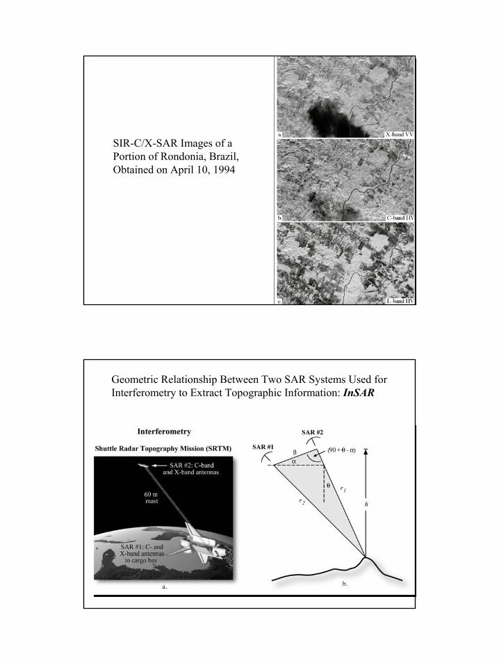
SIR-C/X-SAR Images of a Portion of Rondonia, Brazil, Obtained on April 10, 1994
Geometric Relationship Between Two SAR Systems Used for Interferometry to Extract Topographic Information: InSAR

18
Shuttle Radar Topography Mission (SRTM)
Electrical Characteristics and Relationship with Moisture
One measure of a material's electrical characteristics is the complex dielectric constant, defined as a measure of the ability of a material (vegetation, soil, rock, water, ice) to conduct electrical energy.
Dry surface materials have dielectric constants from 3 to 8 in microwave portion of the spectrum.
Conversely, water has a dielectric constant of approximately 80.
The amount of moisture in soil, on rock surface, or within vegetation tissues may have significant impact on the amount of backscattered radar energy.

19
Electrical Characteristics and Relationship with Moisture
Moist soils reflect more radar energy than dry soil. The amount of soil moisture influences how deep the incident energy penetrates into materials.
The general rule of thumb for how far microwave energy will penetrate into a dry substance is that the penetration should beequal to the wavelength of the radar system.
However,, active microwave energy may penetrate extremely dry soil several meters.
Imaging Radar Applications
Environmental Monitoring• Vegetation mapping• Monitoring vegetation regrowth, timber yields• Detecting flooding underneath canopy, flood plain mapping• Assessing environmental damage to vegetation
Hydrology• Soil moisture maps and vegetation water content monitoring• Snow cover and wetness maps• Measuring rain-fall rates in tropical storms
Oceanography• Monitoring and routing ship traffic• Detection oil slicks (natural and man-made)• Measuring surface current speeds• Sea ice type and monitoring for directing ice-breakers

20
InSAR study of coastal wetlands over southeastern Louisiana
Zhong Lu, U.S. Geological Survey Oh-ig Kwoun, Jet Propulsion Laboratory
Using multi-temporal C-band European Remote-sensing Satellites (ERS)-1/-2 and Canadian Radar Satellite (RADARSAT)-1 synthetic aperture radar (SAR) data over the Louisiana coastal zone to characterize seasonal variations of radar backscatteringaccording to vegetation types and conduct detailed analysis of InSAR imagery to study water level changes of coastal wetlands.
Chapter 2: In Remote Sensing of Coastal Environment (Wang, Editor), Taylor & Francis, 2009

21

22
InSAR-derived water-level changes
InSAR images showing water-level changes in coastal wetlands over southeastern Louisiana. Each fringe (full color cycle) represents a line-of-sight range change of 11.8 cm and 2.83 cm for ALOS and Radarsat-1 interferograms, respectively. Interferogram phase values are unfiltered for coherence comparison and are draped over the SAR intensity image of the early date. Areas of loss of coherence are indicated by random colors.
M – marshes (freshwater, intermediate, brackish, and saline marshes)L – lakeSF – swamp forestBF – bottomland forestAF – agricultural field

23
Advantages of Active Remote Sensing:
• Sending and receiving EMR that can pass through cloud, precipitation
• Images can be obtained at user-specified times, even at night.• Sending and receiving EMR that can penetrate tree canopy, dry
surface, deposits, snow …• Permits imaging at shallow look angles, resulting in different
perspectives that cannot always be obtained using aerial photography.
• Providing information on surface roughness, dielectric properties, and moisture content.
All weather, day-and-night imaging capacity

24
LIDAR (LIght Detection And Ranging)
Is a rapidly emerging technology for determining the shape of the ground surface plus natural and man-made features.
Buildings, trees and power lines are individually discernible features. This data is digital and is directly processed to produce detailed bare earth DEMs at vertical accuracies of 0.15 meters to 1 meter.
Derived products include contour maps, slope/aspect, three-dimensional topographic images, virtual reality visualizations and more.
AS350BA LIDAR Platform

25
The LIDAR instrument consists The LIDAR instrument consists of a of a system controllersystem controller and a and a transmittertransmitter and and receiverreceiver. As the . As the aircraft moves forward along the aircraft moves forward along the lineline--ofof--flight, a scanning mirror flight, a scanning mirror directs pulses of laser light directs pulses of laser light acrossacross--track perpendicular to the track perpendicular to the lineline--ofof--flight.flight.

26
LidarLidar systems generally transmit systems generally transmit pulses toward nadir. The pulses toward nadir. The lidarlidarpulse is spatially confined to pulse is spatially confined to concentrate energy and get concentrate energy and get accurate range estimates. accurate range estimates.
The first and simplest LIDAR The first and simplest LIDAR system collects a profile of nearly system collects a profile of nearly equidistant points along the equidistant points along the sensor's path. sensor's path.
The second technology collects The second technology collects range samples within a swath by range samples within a swath by transmitting the LIDAR pulses transmitting the LIDAR pulses away from nadir, effectively away from nadir, effectively collecting a "cloud" of data points.collecting a "cloud" of data points.
LIDAR ReturnsLIDAR Returns
Depending upon the altitude of the LIDAR Depending upon the altitude of the LIDAR instrument and the angle at which the pulse is instrument and the angle at which the pulse is sent, each pulse illuminates a nearsent, each pulse illuminates a near--circular circular area on the ground called the area on the ground called the instantaneous instantaneous laser footprintlaser footprint, e.g., 30 cm in diameter. , e.g., 30 cm in diameter.
This single pulse can generate one return or This single pulse can generate one return or multiple returns. All of the energy within laser multiple returns. All of the energy within laser pulse A interacts with the ground. One would pulse A interacts with the ground. One would assume that this would generate only a single assume that this would generate only a single return. However, if there are any materials return. However, if there are any materials whatsoever with local relief within the whatsoever with local relief within the instantaneous laser footprint (e.g., grass, small instantaneous laser footprint (e.g., grass, small rocks, twigs), then there will be multiple rocks, twigs), then there will be multiple returns. returns.

27
LIDAR ReturnsLIDAR Returns
PostPost--processing the original data results in processing the original data results in several LIDAR files commonly referred to as:several LIDAR files commonly referred to as:
•• 1st return; 1st return; •• possible intermediate returns; possible intermediate returns; •• last return; andlast return; and•• intensity.intensity.
The The masspointsmasspoints associated with each return file associated with each return file (e.g., 1st return) are distributed throughout the (e.g., 1st return) are distributed throughout the landscape at various densities depending upon landscape at various densities depending upon the scan angle, the number of pulses per the scan angle, the number of pulses per second transmitted (e.g., 50,000 second transmitted (e.g., 50,000 ppspps), aircraft ), aircraft speed, and the materials that the laser pulses speed, and the materials that the laser pulses encountered. Areas on the ground that do not encountered. Areas on the ground that do not yield any LIDARyield any LIDAR--return data are referred to as return data are referred to as data voidsdata voids..
First Return Last Return Bare Earth

28
LIDAR-derived TIN Bare Earth DEM overlaid with Contours
Classification of Landcover based solely on LIDAR-derived Elevation, Slope, and Intensity
blue = buildingsgreen = grasspink = vegetation

29
LIDAR data can be integrated with other data sets, including orthophotos, multispectral, hyperspectral and panchromatic imagery.
LIDAR can be combined with GIS data and other surveying information to generate complex geomorphic-structure mapping products, building renderings, advanced three dimensional modeling/earthworks and many more high quality mapping products.