act ii quick user guide
TRANSCRIPT
Reflex ACT II RD
QUICK USER GUIDENon – Download
1. Act II User Guide.
2. Dip & Depth User Guide.
3. Digital Audit Software Installation Guide.
Reflex ACT II RD
QUICK USER GUIDE
Quick User Guide | 2
Section 1ACT II USER GUIDENon – Download
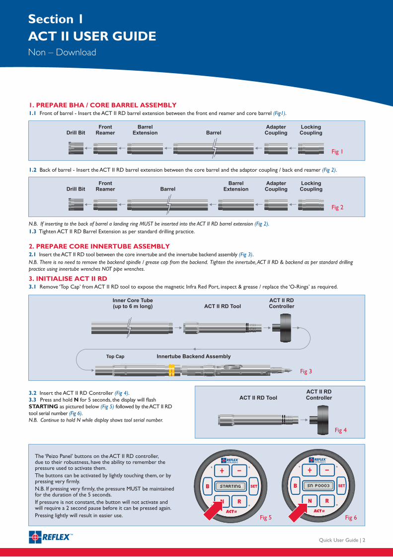
1. PREPARE BHA / CORE BARREL ASSEMBLY1.1 Front of barrel - Insert the ACT II RD barrel extension between the front end reamer and core barrel (Fig1).
1.2 Back of barrel - Insert the ACT II RD barrel extension between the core barrel and the adaptor coupling / back end reamer (Fig 2).
N.B. If inserting to the back of barrel a landing ring MUST be inserted into the ACT II RD barrel extension (Fig 2).1.3 Tighten ACT II RD Barrel Extension as per standard drilling practice.
2. PREPARE CORE INNERTUBE ASSEMBLY2.1 Insert the ACT II RD tool between the core innertube and the innertube backend assembly (Fig 3).N.B. There is no need to remove the backend spindle / grease cap from the backend. Tighten the innertube, ACT II RD & backend as per standard drilling practice using innertube wrenches NOT pipe wrenches.
3. INITIALISE ACT II RD3.1 Remove ‘Top Cap’ from ACT II RD tool to expose the magnetic Infra Red Port, inspect & grease / replace the ‘O-Rings’ as required.
3.2 Insert the ACT II RD Controller (Fig 4).3.3 Press and hold N for 5 seconds, the display will flash STARTING as pictured below (Fig 5) followed by the ACT II RD tool serial number (Fig 6). N.B. Continue to hold N while display shows tool serial number.
The ‘Peizo Panel’ buttons on the ACT II RD controller, due to their robustness, have the ability to remember the pressure used to activate them.The buttons can be activated by lightly touching them, or by pressing very firmly.N.B. If pressing very firmly, the pressure MUST be maintained for the duration of the 5 seconds.If pressure is not constant, the button will not activate and will require a 2 second pause before it can be pressed again.Pressing lightly will result in easier use.
Quick User Guide | 3
Section 1ACT II USER GUIDENon – Download
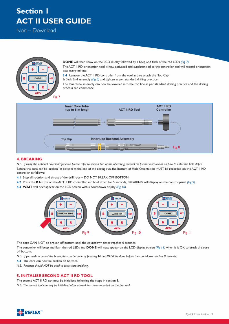
DONE will then show on the LCD display followed by a beep and flash of the red LEDs (Fig 7).
The ACT II RD orientation tool is now activated and synchronised to the controller and will record orientation data every minute
3.4 Remove the ACT II RD controller from the tool and re attach the ‘Top Cap’ & Back End assembly (Fig 8) and tighten as per standard drilling practice.
The Innertube assembly can now be lowered into the rod line as per standard drilling practice and the drilling process can commence.
4. BREAKINGN.B. If using the optional download function please refer to section two of the operating manual for further instructions on how to enter the hole depth.
Before the core can be ‘broken’ of bottom at the end of the coring run, the Bottom of Hole Orientation MUST be recorded on the ACT II RD controller as follows:
4.1 Stop all rotation and thrust of the drill rods – DO NOT BREAK OFF BOTTOM.
4.2 Press the B button on the ACT II RD controller and hold down for 5 seconds, BREAKING will display on the control panel (Fig 9).
4.3 WAIT will next appear on the LCD screen with a countdown display (Fig 10).
The core CAN NOT be broken off bottom until the countdown timer reaches 0 seconds.
The controller will beep and flash the red LEDs and DONE will next appear on the LCD display screen (Fig 11) when it is OK to break the core off bottom.
N.B. If you wish to cancel the break, this can be done by pressing N but MUST be done before the countdown reaches 0 seconds.
4.4 The core can now be broken off bottom.
N.B. Rotation should NOT be used to assist core breaking.
5. INITALISE SECOND ACT II RD TOOL The second ACT II RD can now be initialised following the steps in section 3.
N.B. The second tool can only be initialised after a break has been recorded on the first tool.
Quick User Guide | 4
Section 1ACT II USER GUIDENon – Download
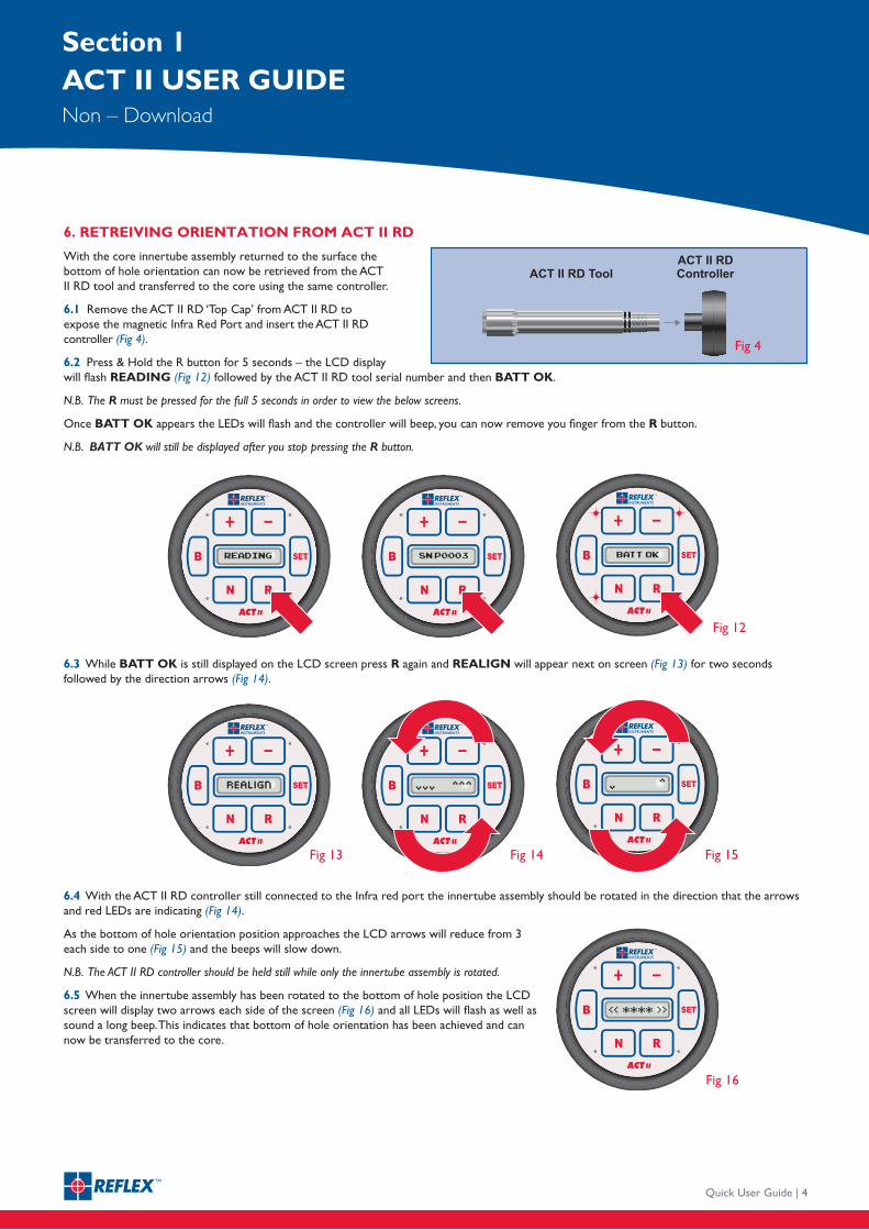
6. RETREIVING ORIENTATION FROM ACT II RD
With the core innertube assembly returned to the surface the bottom of hole orientation can now be retrieved from the ACT II RD tool and transferred to the core using the same controller.
6.1 Remove the ACT II RD ‘Top Cap’ from ACT II RD to expose the magnetic Infra Red Port and insert the ACT II RD controller (Fig 4).
6.2 Press & Hold the R button for 5 seconds – the LCD display will flash READING (Fig 12) followed by the ACT II RD tool serial number and then BATT OK.
N.B. The R must be pressed for the full 5 seconds in order to view the below screens.
Once BATT OK appears the LEDs will flash and the controller will beep, you can now remove you finger from the R button.
N.B. BATT OK will still be displayed after you stop pressing the R button.
6.3 While BATT OK is still displayed on the LCD screen press R again and REALIGN will appear next on screen (Fig 13) for two seconds followed by the direction arrows (Fig 14).
6.4 With the ACT II RD controller still connected to the Infra red port the innertube assembly should be rotated in the direction that the arrows and red LEDs are indicating (Fig 14).
As the bottom of hole orientation position approaches the LCD arrows will reduce from 3 each side to one (Fig 15) and the beeps will slow down.
N.B. The ACT II RD controller should be held still while only the innertube assembly is rotated.
6.5 When the innertube assembly has been rotated to the bottom of hole position the LCD screen will display two arrows each side of the screen (Fig 16) and all LEDs will flash as well as sound a long beep. This indicates that bottom of hole orientation has been achieved and can now be transferred to the core.
Quick User Guide | 5
Section 1ACT II USER GUIDENon – Download
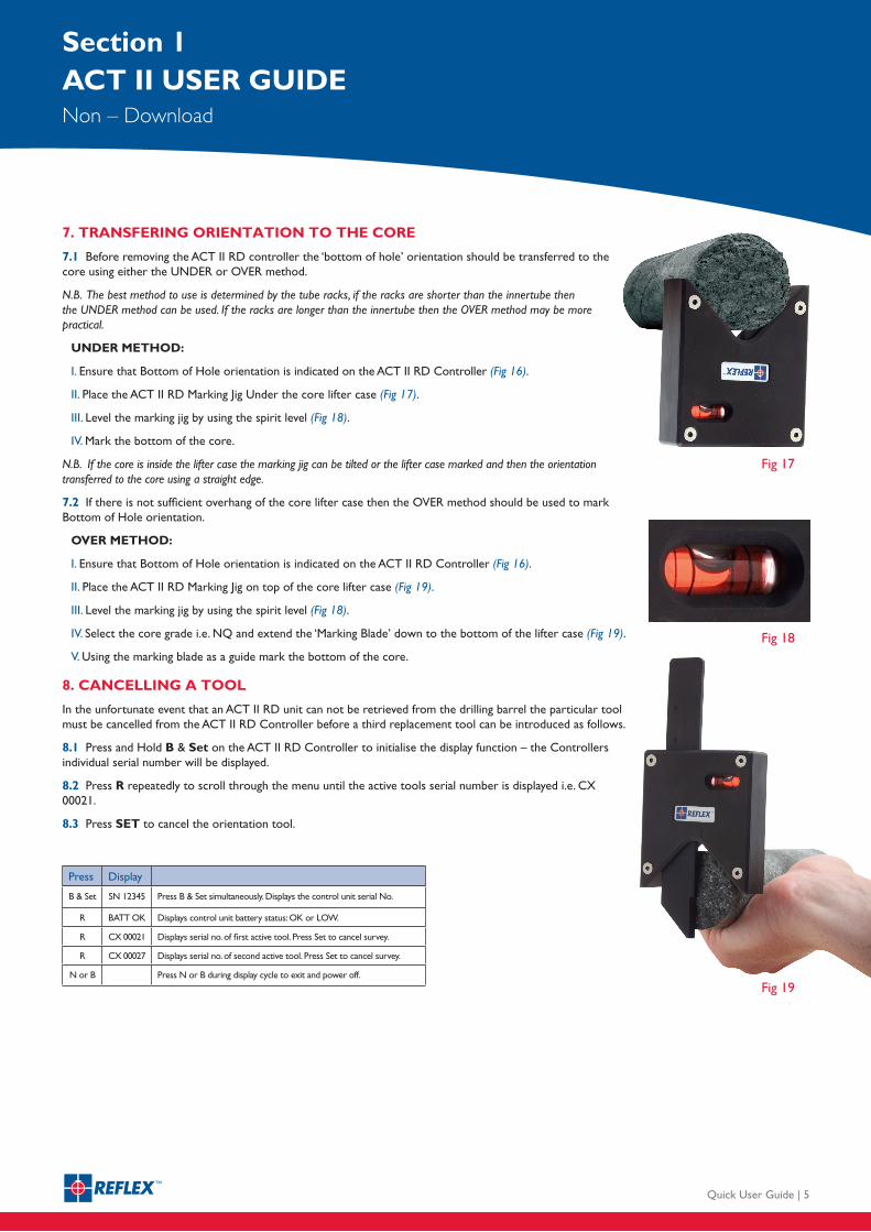
7. TRANSFERING ORIENTATION TO THE CORE
7.1 Before removing the ACT II RD controller the ‘bottom of hole’ orientation should be transferred to the core using either the UNDER or OVER method.
N.B. The best method to use is determined by the tube racks, if the racks are shorter than the innertube then the UNDER method can be used. If the racks are longer than the innertube then the OVER method may be more practical.
UNDER METHOD:
I. Ensure that Bottom of Hole orientation is indicated on the ACT II RD Controller (Fig 16).
II. Place the ACT II RD Marking Jig Under the core lifter case (Fig 17).
III. Level the marking jig by using the spirit level (Fig 18).
IV. Mark the bottom of the core.
N.B. If the core is inside the lifter case the marking jig can be tilted or the lifter case marked and then the orientation transferred to the core using a straight edge.
7.2 If there is not sufficient overhang of the core lifter case then the OVER method should be used to mark Bottom of Hole orientation.
OVER METHOD:
I. Ensure that Bottom of Hole orientation is indicated on the ACT II RD Controller (Fig 16).
II. Place the ACT II RD Marking Jig on top of the core lifter case (Fig 19).
III. Level the marking jig by using the spirit level (Fig 18).
IV. Select the core grade i.e. NQ and extend the ‘Marking Blade’ down to the bottom of the lifter case (Fig 19).
V. Using the marking blade as a guide mark the bottom of the core.
8. CANCELLING A TOOL
In the unfortunate event that an ACT II RD unit can not be retrieved from the drilling barrel the particular tool must be cancelled from the ACT II RD Controller before a third replacement tool can be introduced as follows.
8.1 Press and Hold B & Set on the ACT II RD Controller to initialise the display function – the Controllers individual serial number will be displayed.
8.2 Press R repeatedly to scroll through the menu until the active tools serial number is displayed i.e. CX 00021.
8.3 Press SET to cancel the orientation tool.
Press Display
B & Set SN 12345 Press B & Set simultaneously. Displays the control unit serial No.
R BATT OK Displays control unit battery status: OK or LOW.
R CX 00021 Displays serial no. of first active tool. Press Set to cancel survey.
R CX 00027 Displays serial no. of second active tool. Press Set to cancel survey.
N or B Press N or B during display cycle to exit and power off.
Reflex ACT II RD
QUICK USER GUIDENon – Download
Quick User Guide | 6
Section 2ACT II USER GUIDEDepth & Dip Display Function
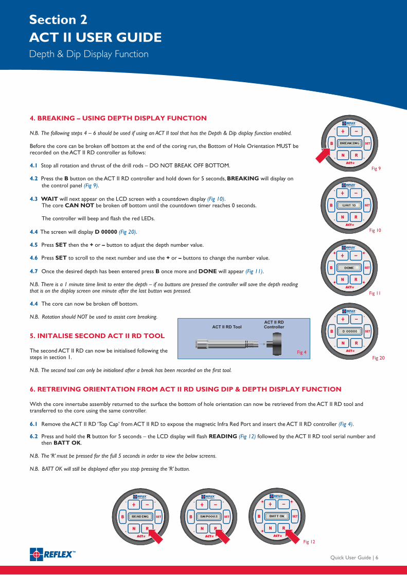
4. BREAKING – USING DEPTH DISPLAY FUNCTION
N.B. The following steps 4 – 6 should be used if using an ACT II tool that has the Depth & Dip display function enabled.
Before the core can be broken off bottom at the end of the coring run, the Bottom of Hole Orientation MUST be recorded on the ACT II RD controller as follows:
4.1 Stop all rotation and thrust of the drill rods – DO NOT BREAK OFF BOTTOM.
4.2 Press the B button on the ACT II RD controller and hold down for 5 seconds, BREAKING will display on the control panel (Fig 9).
4.3 WAIT will next appear on the LCD screen with a countdown display (Fig 10). The core CAN NOT be broken off bottom until the countdown timer reaches 0 seconds. The controller will beep and flash the red LEDs.
4.4 The screen will display D 00000 (Fig 20).
4.5 Press SET then the + or – button to adjust the depth number value.
4.6 Press SET to scroll to the next number and use the + or – buttons to change the number value.
4.7 Once the desired depth has been entered press B once more and DONE will appear (Fig 11).
N.B. There is a 1 minute time limit to enter the depth – if no buttons are pressed the controller will save the depth reading that is on the display screen one minute after the last button was pressed.
4.4 The core can now be broken off bottom.
N.B. Rotation should NOT be used to assist core breaking.
5. INITALISE SECOND ACT II RD TOOL
The second ACT II RD can now be initialised following the steps in section 1.
N.B. The second tool can only be initialised after a break has been recorded on the first tool.
6. RETREIVING ORIENTATION FROM ACT II RD USING DIP & DEPTH DISPLAY FUNCTION
With the core innertube assembly returned to the surface the bottom of hole orientation can now be retrieved from the ACT II RD tool and transferred to the core using the same controller.
6.1 Remove the ACT II RD ‘Top Cap’ from ACT II RD to expose the magnetic Infra Red Port and insert the ACT II RD controller (Fig 4).
6.2 Press and hold the R button for 5 seconds – the LCD display will flash READING (Fig 12) followed by the ACT II RD tool serial number and then BATT OK.
N.B. The ‘R’ must be pressed for the full 5 seconds in order to view the below screens.
N.B. BATT OK will still be displayed after you stop pressing the ‘R’ button.
Reflex ACT II RD
QUICK USER GUIDENon – Download
Quick User Guide | 7
Section 2DEPTH & DIP USER GUIDEDepth & Dip Display Function
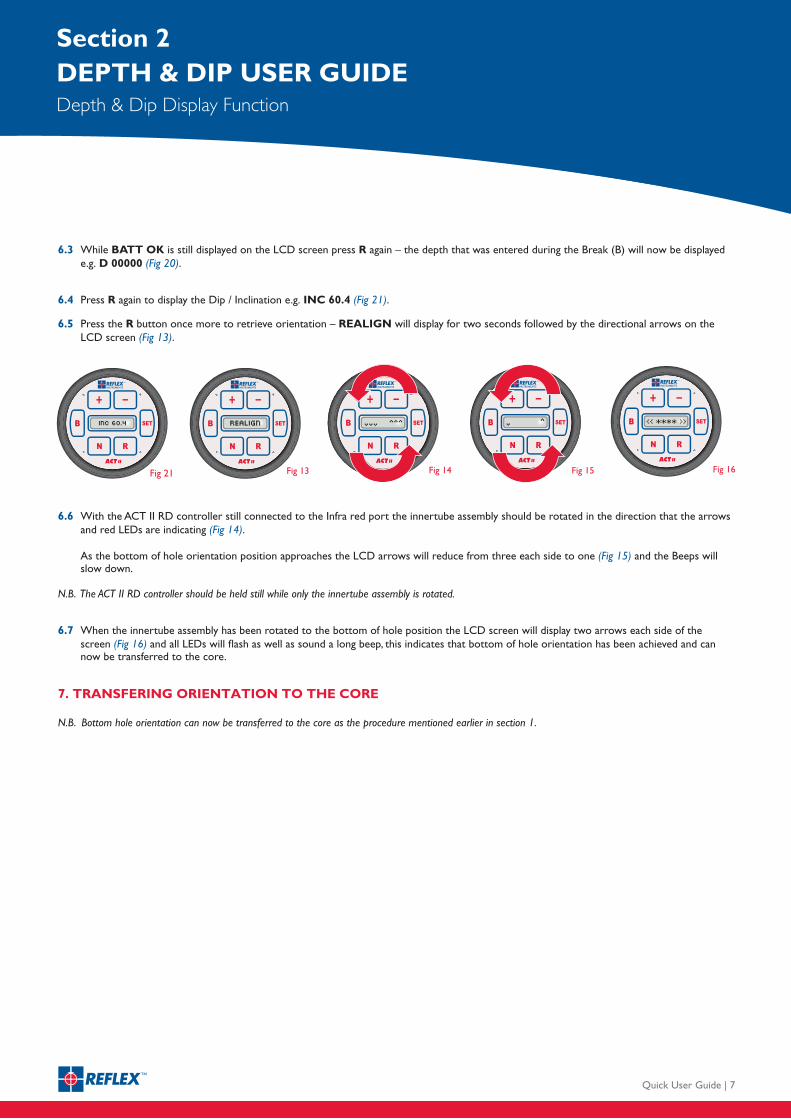
6.3 While BATT OK is still displayed on the LCD screen press R again – the depth that was entered during the Break (B) will now be displayed e.g. D 00000 (Fig 20).
6.4 Press R again to display the Dip / Inclination e.g. INC 60.4 (Fig 21).
6.5 Press the R button once more to retrieve orientation – REALIGN will display for two seconds followed by the directional arrows on the LCD screen (Fig 13).
6.6 With the ACT II RD controller still connected to the Infra red port the innertube assembly should be rotated in the direction that the arrows and red LEDs are indicating (Fig 14).
As the bottom of hole orientation position approaches the LCD arrows will reduce from three each side to one (Fig 15) and the Beeps will slow down.
N.B. The ACT II RD controller should be held still while only the innertube assembly is rotated.
6.7 When the innertube assembly has been rotated to the bottom of hole position the LCD screen will display two arrows each side of the screen (Fig 16) and all LEDs will flash as well as sound a long beep, this indicates that bottom of hole orientation has been achieved and can now be transferred to the core.
7. TRANSFERING ORIENTATION TO THE CORE
N.B. Bottom hole orientation can now be transferred to the core as the procedure mentioned earlier in section 1.
Reflex ACT II RD
QUICK USER GUIDENon – Download
Quick User Guide | 8
Section 3DIGITAL AUDIT SOFTWARE INSTALLATION GUIDEFor Data Download Function
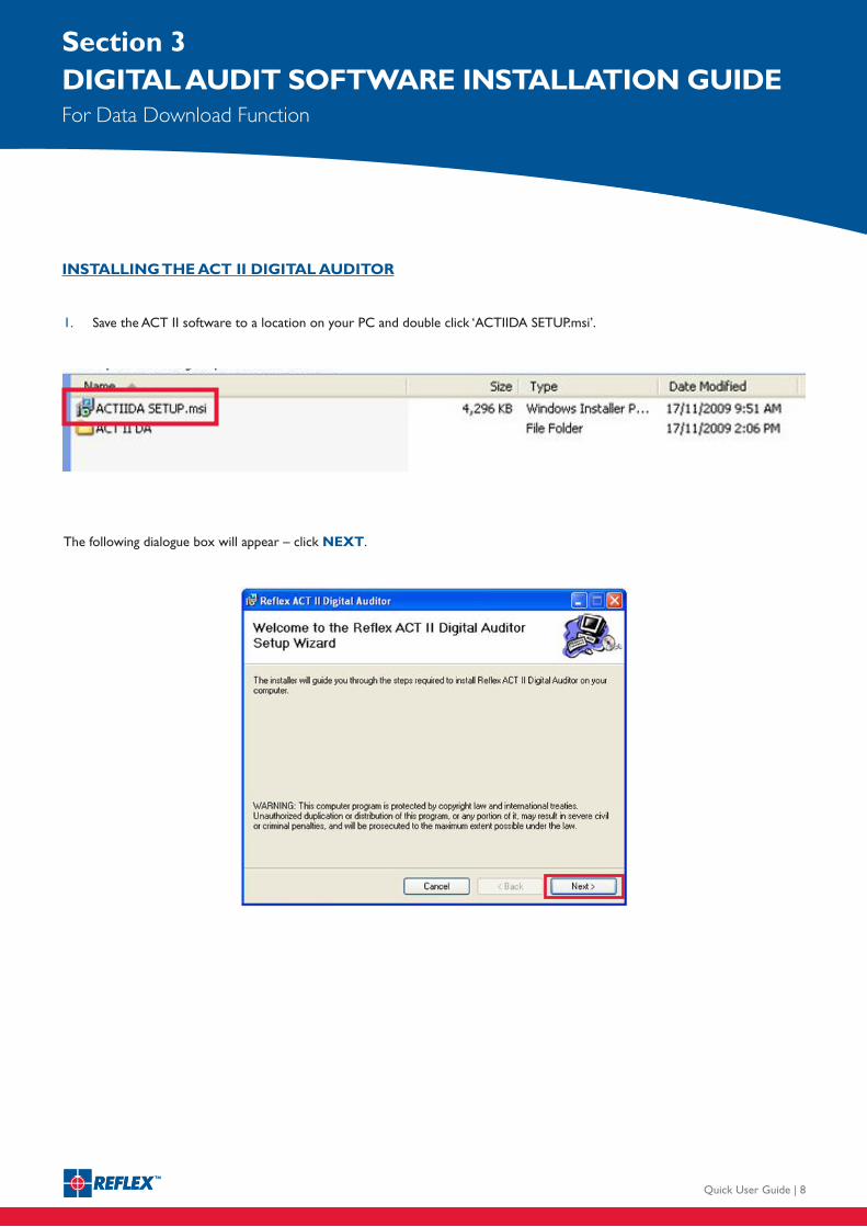
1. Save the ACT II software to a location on your PC and double click ‘ACTIIDA SETUP.msi’.
The following dialogue box will appear – click NEXT.
INSTALLING THE ACT II DIGITAL AUDITOR
Reflex ACT II RD
QUICK USER GUIDENon – Download
Quick User Guide | 9
Section 3DIGITAL AUDIT SOFTWARE INSTALLATION GUIDEFor Data Download Function
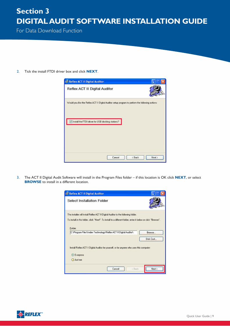
3. The ACT II Digital Audit Software will install in the Program Files folder – if this location is OK click NEXT, or select BROWSE to install in a different location.
2. Tick the install FTDI driver box and click NEXT.
Reflex ACT II RD
QUICK USER GUIDENon – Download
Quick User Guide | 10
Section 3DIGITAL AUDIT SOFTWARE INSTALLATION GUIDEFor Data Download Function
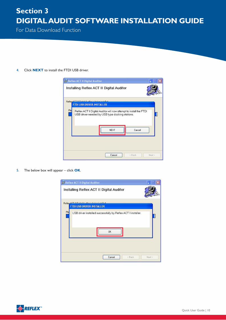
5. The below box will appear – click OK.
4. Click NEXT to install the FTDI USB driver.
Reflex ACT II RD
QUICK USER GUIDENon – Download
Quick User Guide | 11
Section 3DIGITAL AUDIT SOFTWARE INSTALLATION GUIDEFor Data Download Function
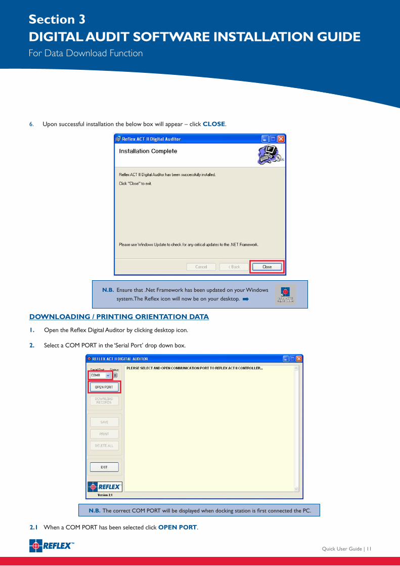
1. Open the Reflex Digital Auditor by clicking desktop icon.
2. Select a COM PORT in the ‘Serial Port’ drop down box.
DOWNLOADING / PRINTING ORIENTATION DATA
6. Upon successful installation the below box will appear – click CLOSE.
N.B. The correct COM PORT will be displayed when docking station is first connected the PC.
N.B. Ensure that .Net Framework has been updated on your Windows
system.The Reflex icon will now be on your desktop. ➡
2.1 When a COM PORT has been selected click OPEN PORT.
Reflex ACT II RD
QUICK USER GUIDENon – Download
Quick User Guide | 12
Section 3DIGITAL AUDIT SOFTWARE INSTALLATION GUIDEFor Data Download Function
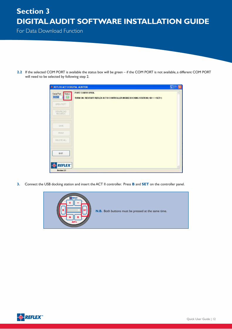
N.B. Both buttons must be pressed at the same time.
3. Connect the USB docking station and insert the ACT II controller. Press B and SET on the controller panel.
2.2 If the selected COM PORT is available the status box will be green – if the COM PORT is not available, a different COM PORT will need to be selected by following step 2.
Reflex ACT II RD
QUICK USER GUIDENon – Download
Quick User Guide | 13
Section 3DIGITAL AUDIT SOFTWARE INSTALLATION GUIDEFor Data Download Function
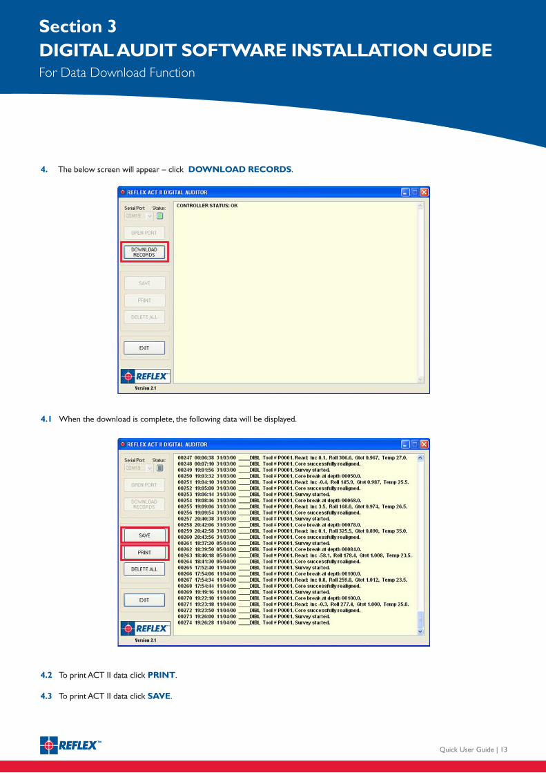
4.1 When the download is complete, the following data will be displayed.
4. The below screen will appear – click DOWNLOAD RECORDS.
4.2 To print ACT II data click PRINT.
4.3 To print ACT II data click SAVE.
Reflex ACT II RD
QUICK USER GUIDENon – Download
Quick User Guide | 14
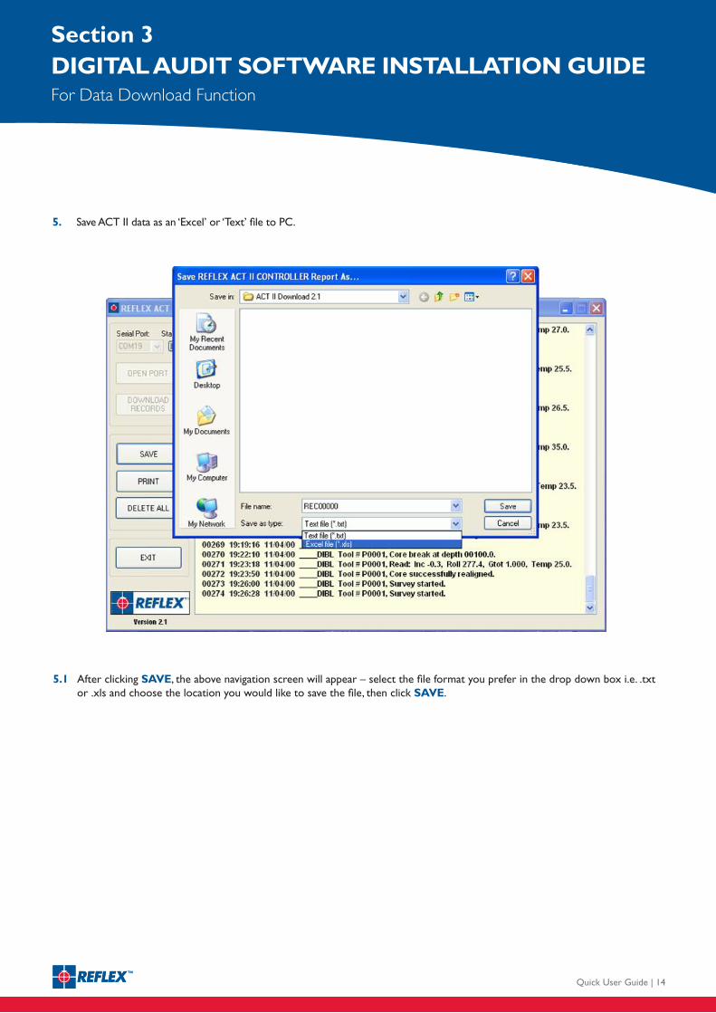
5. Save ACT II data as an ‘Excel’ or ‘Text’ file to PC.
5.1 After clicking SAVE, the above navigation screen will appear – select the file format you prefer in the drop down box i.e. .txt or .xls and choose the location you would like to save the file, then click SAVE.
Section 3DIGITAL AUDIT SOFTWARE INSTALLATION GUIDEFor Data Download Function
Reflex ACT II RD
QUICK USER GUIDENon – Download
Quick User Guide | 15
Section 3DIGITAL AUDIT SOFTWARE INSTALLATION GUIDEFor Data Download Function
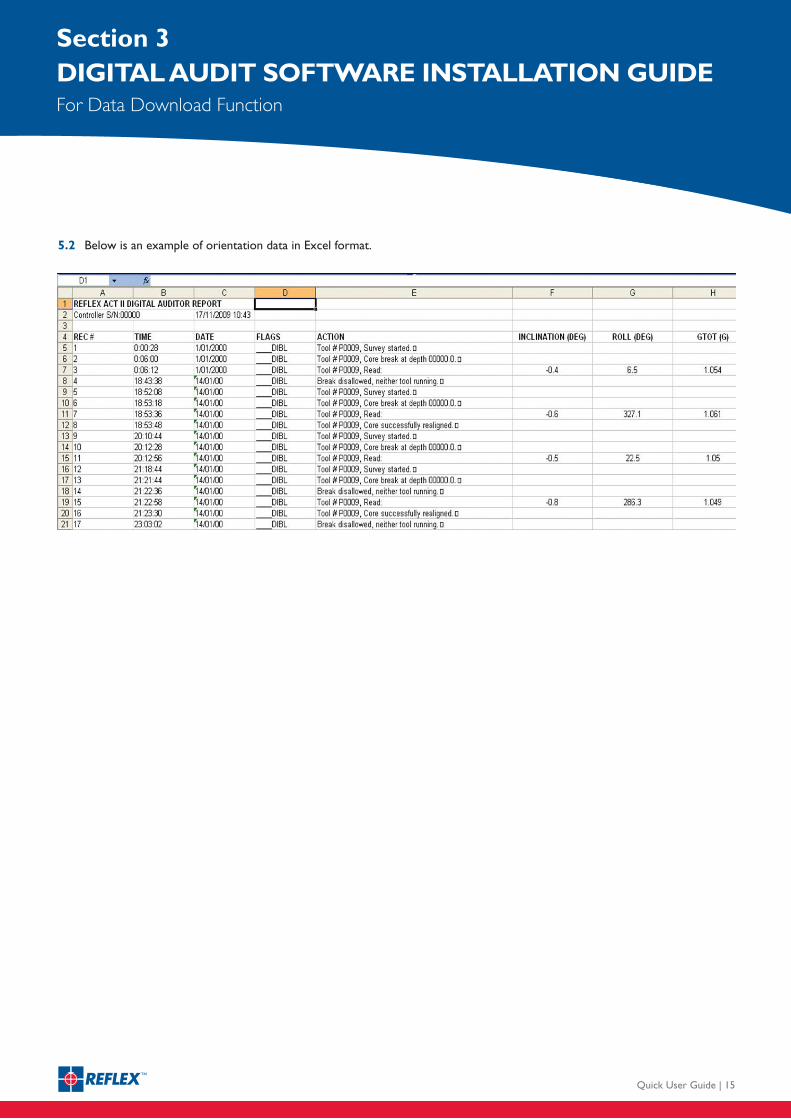
5.2 Below is an example of orientation data in Excel format.

REFLEX ASIA PACIFIC T +61 (0) 8 9445 4020
REFLEX NORTH AMERICA T +1 (705) 235 2169
REFLEX SOUTH AMERICA T +56 (2) 899 9303
REFLEX SOUTH AFRICA T +27 (0) 11 864 3467
REFLEX EUROPE T +44 (0) 1273 483 700
For further information, orto contact your nearest distributor, please visit
www.reflexinstruments.com