acs applied materials & interfaces pcmfr6utq9wrehisftft ... · kim, magkiriadou, rhee, lee,...
TRANSCRIPT
This document is the Accepted Manuscript version of a Published Work that appeared in final form in ACS Applied Materials & Interfaces,
copyright © American Chemical Society after peer review and technical editing by the publisher. To access the final edited and published
work see http://pubs.acs.org/articlesonrequest/AOR-pCMFR6UTq9WREhISfTfT
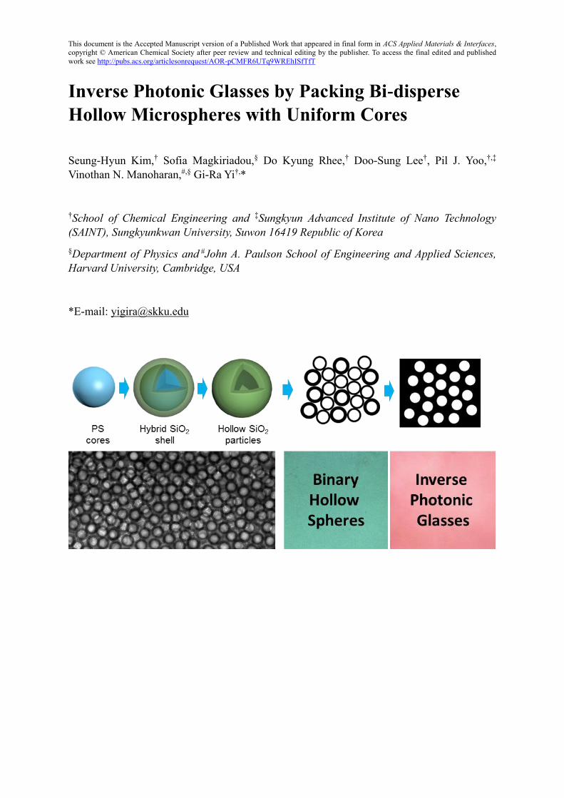
Inverse Photonic Glasses by Packing Bi-disperse
Hollow Microspheres with Uniform Cores
Seung-Hyun Kim,† Sofia Magkiriadou,§ Do Kyung Rhee,† Doo-Sung Lee†, Pil J. Yoo,†,‡
Vinothan N. Manoharan,#,§ Gi-Ra Yi†,*
†School of Chemical Engineering and ‡Sungkyun Advanced Institute of Nano Technology
(SAINT), Sungkyunkwan University, Suwon 16419 Republic of Korea
§Department of Physics and #John A. Paulson School of Engineering and Applied Sciences,
Harvard University, Cambridge, USA
*E-mail: [email protected]
Kim, Magkiriadou, Rhee, Lee, Yoo, Manoharan, Yi, ACS Applied Materials & Interfaces 9: 24155 (2017)
2
Abstract
A major fabrication challenge is producing disordered photonic materials with angle-
independent structural red color. Theoretical work has shown that such color can be produced
by fabricating inverse photonic glasses with monodisperse, non-touching voids in a silica
matrix. Here we demonstrate a route toward such materials and show that they have angle-
independent red color. We first synthesize monodisperse hollow silica particles with precisely
controlled shell thickness, then make glassy colloidal structures by mixing two types of
hollow particles with the same core size and different shell thicknesses. We then infiltrate the
interstices with index-matched polymers, producing disordered porous materials with
uniform, non-touching air voids. This procedure allows us to control the light-scattering form
factor and structure factor of these porous materials independently, which is not possible to
do in photonic glasses consisting of packed solid particles. The structure factor can be
controlled by the shell thickness, which sets the distance between pores, while the pore size
determines the peak wavevector of the form factor, which can be set below the visible range
to keep the main structural color pure. By using a binary mixture of 246-nm and 268-nm
hollow silica particles with 180-nm cores in an index-matched polymer matrix, we achieve
angle-independent red color that can be tuned by controlling the shell thickness. Importantly,
the width of the reflection peak can be kept constant, even for larger inter-particle distances.
Keywords: Photonic glass, Hollow silica, Inverse, Templates, Self-assembly
Kim, Magkiriadou, Rhee, Lee, Yoo, Manoharan, Yi, ACS Applied Materials & Interfaces 9: 24155 (2017)
3
Introduction
Inspired by nanostructures in bird feathers or firefly lantern,1-3 a new kind of structurally
colored material, called a “photonic glass,” has recently been developed.4-6 Unlike photonic
crystals, which show iridescent colors—that is, colors that depend on both the viewing angle
and the orientation of the sample—photonic glasses can have angle-independent colors that
are indistinguishable from traditional dyes or pigments.
One way to produce such materials is by quickly drying colloidal suspensions.7-9 However,
this approach yields only blue or green colors, and never red. Magkiriadou et al.10 used a
single-scattering model to explain why red is difficult to achieve: When colloidal glasses
scatter light, two peaks arise in the reflection spectra: one comes from the form factor and is
determined primarily by the size and refractive index of individual particles, while the other
comes from the structure factor and is determined primarily by the inter-particle distance.11
However, in glassy packings of spheres these two peaks cannot be independently controlled,
because the inter-particle spacing is determined by the particle size. When the sphere size is
such that the peak of the structure factor corresponds to a reflected green or blue wavelength,
the peak of the form factor is in the ultraviolet (UV) and cannot be seen by the human eye. If
one increases the sphere size, so as to increase the average inter-particle distance and thus
shift the peak of the structure factor wavelengths, the peak of the form factor enters the
visible region, making the structural color a mix of blue and red that appears magenta.12-14
We seek to create a red, angle-independent, pure structural color from a colloidal sample. By
“red” we mean that there is a single peak in the red part of the reflection spectrum (about
600-700 nm). Samples that show a secondary peak at short wavelengths are not red, but
Kim, Magkiriadou, Rhee, Lee, Yoo, Manoharan, Yi, ACS Applied Materials & Interfaces 9: 24155 (2017)
4
instead appear magenta, as noted above. Thus, we seek to eliminate the second peak entirely.
By “angle-independent” we mean that the color does not shift with the viewing angle and
orientation of the sample. Finally, by “pure structural color,” we mean that the color arises
from the process of interference of light scattered from the sample, and not from absorption.
Many recent papers discuss the use of melanin or similar materials in concert with colloidal
assembly to create red colors.15-19 The melanin absorbs blue light, 15-16 which can eliminate
the secondary peak in the blue. Here we seek to avoid the use of melanin and other dyes,
because wavelength-specific absorption is the basis of traditional color. Structural color is
special because it relies on wavelength-dependent interference. We believe the distinction is
important because structural color has a number of advantages over traditional color in
applications—it is in principle resistant to fading, and a number of different colors can be
made using the same materials. These advantages are lessened with the use of wavelength-
dependent absorption. Thus, we seek to produce a “pure” structural color using only non-
absorbing particles and wavelength-independent absorption. Moreover, we aim to make
materials in which not only the position, but also the width of the structural color peak can be
controlled, independently of one another. To our knowledge, this feature has not been
demonstrated previously.
One way to make red, angle-independent, red structural color is to decouple the structure and
form factors so that the peak of the structure factor is in the visible but the peak of the form
factor remains in the UV region. Park et al. showed that this can be done by making a
photonic glass consisting of PS-poly(N-isopropylacrylamide-co-AAc) core-shell particles.20
The hydrogel shell can be swollen with so much water that it has approximately the same
index of refraction as the fluid between the spheres. Thus, the form factor is controlled almost
Kim, Magkiriadou, Rhee, Lee, Yoo, Manoharan, Yi, ACS Applied Materials & Interfaces 9: 24155 (2017)
5
entirely by the cores, and the interparticle distance by the shells. By using small PS cores, the
peak of the form factor can be placed in the UV, and by using large shells, the peak of the
structure factor can be shifted to the red (or any other color). A similar approach was
developed earlier by Ueno et al., who used small silica particles coated with PMMA
stabilizer to form disordered colloidal structures in an ionic liquid, resulting in angle-
independent structural colors of blue, green, and red.21 In both of these approaches, however,
the particles must remain dispersed in the liquid. It is not possible to dry the composites to
make solid pieces of photonic glasses, which may be needed for applications such as coatings
or paints. Recently, Yang and her colleagues reported structurally colored materials formed
by spheres with bumpy shells. However, this approach did not completely separate the form
factor from the structure factor.22
A different approach to red, angle-independent, pure structural color that does not require a
fluid medium relies on using low-refractive-index particles in a high-index matrix.
Magkiriadou et al.23 showed that the low refractive index inside the particles reduces the
optical path length of light traveling within them, thus allowing the form factor to be shifted
to the UV. However, for optimal red color the low-refractive-index particles should not touch
one another.
Packings of such particles are called “inverse photonic glasses,” and several methods have
been developed to make them. For example, small particles can be embedded in a medium
and then removed, leaving disordered porous materials; examples include polystyrene (PS)
particles embedded in a silica matrix and then dissolved10 and silica particles that are
dispersed in a photo-curable resin that is then cross-linked, leaving a composite with a
Kim, Magkiriadou, Rhee, Lee, Yoo, Manoharan, Yi, ACS Applied Materials & Interfaces 9: 24155 (2017)
6
disordered packing of silica particles that can be etched away.24 Both approaches yield red
colors as predicted. In these “kinetic” approaches where the colloidal glass is formed in a
reactive medium that is solidified, the inter-particle distance is controlled by the volume
fraction. To keep the particles from touching one another, the volume fractions must be low,
and thus the peak of the structure factor is typically broader than that obtained in a dense
random packing, resulting in less saturated colors at longer wavelengths.
In this report, we describe a method for making solid inverse photonic glasses where the
width of the reflection peak does not change with wavelength. We achieve this by packing
hollow spheres and then filling the interstices with a polymer that is index-matched to the
sphere shells. The hollow particles are prepared by coating polystyrene beads with
organically modified silane, then burning off the polystyrene. This procedure allows us to
precisely control the shell thickness between 20 nm and 50 nm. By changing the thickness of
the shells, we can change the average spacing between the voids within them, and thus we
control the color. Because the volume fraction of the spheres is the same for all colors, the
width of the peak in the structure factor does not change. Furthermore, the small size of the
empty core ensures that the peak of the form factor is in the UV. To avoid crystallization, we
use a binary mixture of hollow spheres with nearly equal sizes and a stoichiometric ratio near
1:1.25 This fabrication method produces dry samples with uniform air voids that are not
interconnected, which Magkiriadou et al.23 showed is important for shifting the peak of the
form factor to the UV and keeping the second peak of the structure factor in the visible.
Results and Discussion
Synthesis of hollow silica particles.
Kim, Magkiriadou, Rhee, Lee, Yoo, Manoharan, Yi, ACS Applied Materials & Interfaces 9: 24155 (2017)
7
We prepare monodisperse hollow particles by coating silica on polystyrene (PS) particles and
burning out the organic part. For consistent formation of disordered structures, it is important
to make monodisperse hollow particles with controlled shell thickness. There are many
experimental approaches to prepare uniform hollow silica particles,26-30 which mostly involve
sol-gel reactions on latex particles. However, it is still challenging to prepare dispersions of
monodisperse hollow spheres, because the particles may aggregate into dimers during shell
growth or during the calcination process that removes the cores. Moreover, it is not a trivial
task to re-disperse them after heat treatment, which can significantly sinter the particles
together.
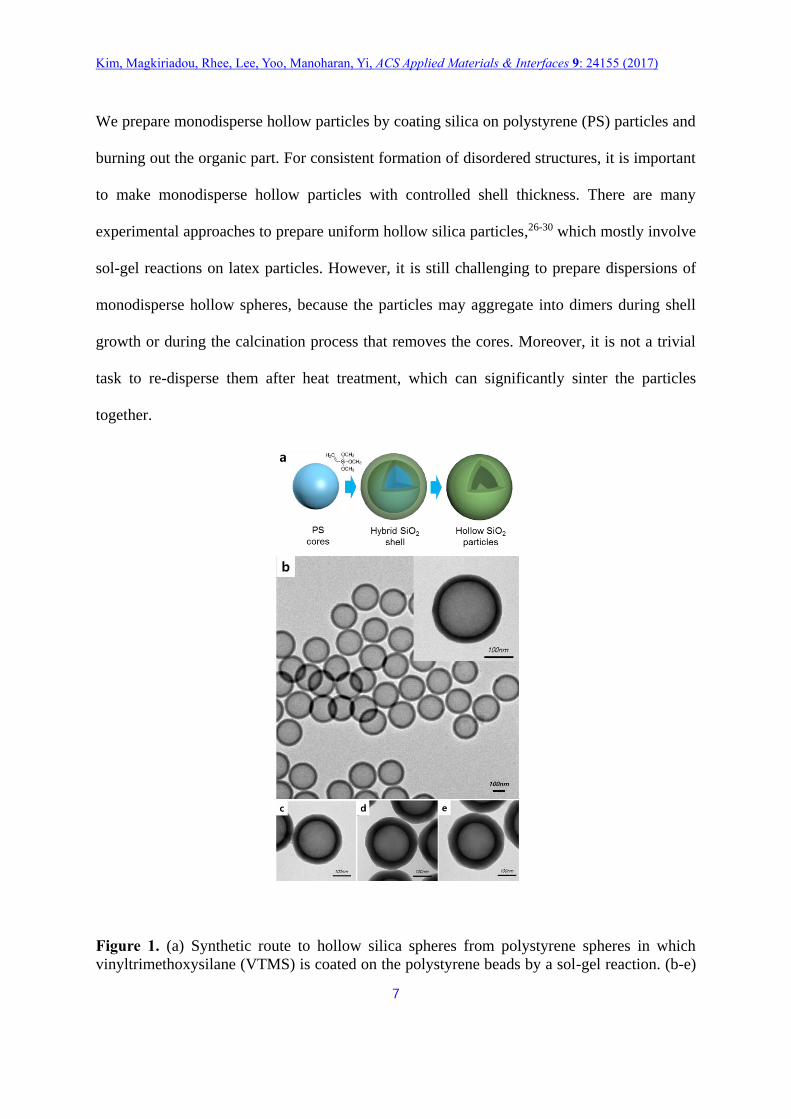
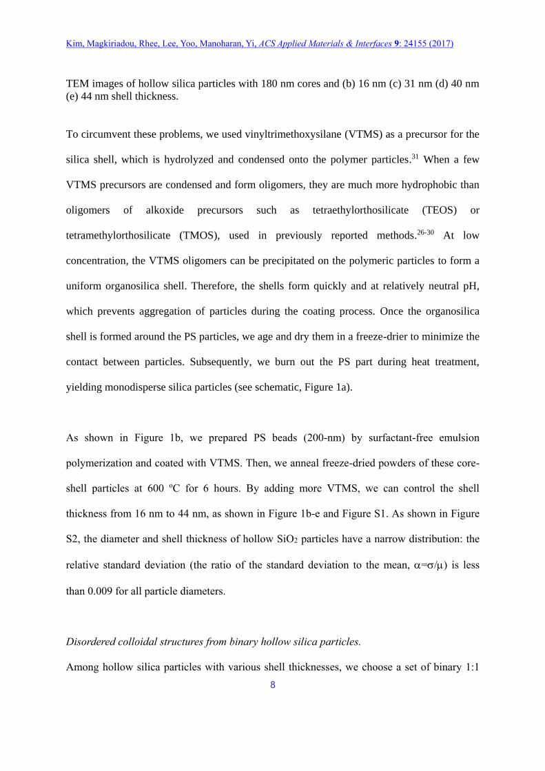
Figure 1. (a) Synthetic route to hollow silica spheres from polystyrene spheres in which
vinyltrimethoxysilane (VTMS) is coated on the polystyrene beads by a sol-gel reaction. (b-e)
Kim, Magkiriadou, Rhee, Lee, Yoo, Manoharan, Yi, ACS Applied Materials & Interfaces 9: 24155 (2017)
8
TEM images of hollow silica particles with 180 nm cores and (b) 16 nm (c) 31 nm (d) 40 nm
(e) 44 nm shell thickness.
To circumvent these problems, we used vinyltrimethoxysilane (VTMS) as a precursor for the
silica shell, which is hydrolyzed and condensed onto the polymer particles.31 When a few
VTMS precursors are condensed and form oligomers, they are much more hydrophobic than
oligomers of alkoxide precursors such as tetraethylorthosilicate (TEOS) or
tetramethylorthosilicate (TMOS), used in previously reported methods.26-30 At low
concentration, the VTMS oligomers can be precipitated on the polymeric particles to form a
uniform organosilica shell. Therefore, the shells form quickly and at relatively neutral pH,
which prevents aggregation of particles during the coating process. Once the organosilica
shell is formed around the PS particles, we age and dry them in a freeze-drier to minimize the
contact between particles. Subsequently, we burn out the PS part during heat treatment,
yielding monodisperse silica particles (see schematic, Figure 1a).
As shown in Figure 1b, we prepared PS beads (200-nm) by surfactant-free emulsion
polymerization and coated with VTMS. Then, we anneal freeze-dried powders of these core-
shell particles at 600 oC for 6 hours. By adding more VTMS, we can control the shell
thickness from 16 nm to 44 nm, as shown in Figure 1b-e and Figure S1. As shown in Figure
S2, the diameter and shell thickness of hollow SiO2 particles have a narrow distribution: the
relative standard deviation (the ratio of the standard deviation to the mean, =/) is less
than 0.009 for all particle diameters.
Disordered colloidal structures from binary hollow silica particles.
Among hollow silica particles with various shell thicknesses, we choose a set of binary 1:1
Kim, Magkiriadou, Rhee, Lee, Yoo, Manoharan, Yi, ACS Applied Materials & Interfaces 9: 24155 (2017)
9
colloidal mixtures by number of particle that, as shown in previous work,9,25,32 yields a
disordered structure and not a binary crystal. We also add carbon nanotube (CNT, ~0.003 wt%
in colloidal glass) to suppress multiple scattering over a broad range of wavelengths.7 Notably,
the average size of the binary mixture corresponds to the core-to-core distance (d), which
determines the wavelength inside the material (2d) corresponding to the peak of the
structure factor in backscattering (=). The peak wavevector (q) of the structure factor is
determined from the following equation9-10:
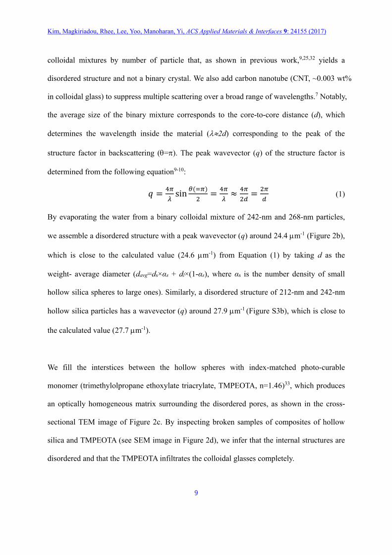
𝑞 =4𝜋
𝜆sin
𝜃(=𝜋)
2=
4𝜋
𝜆≈
4𝜋
2𝑑=
2𝜋
𝑑 (1)
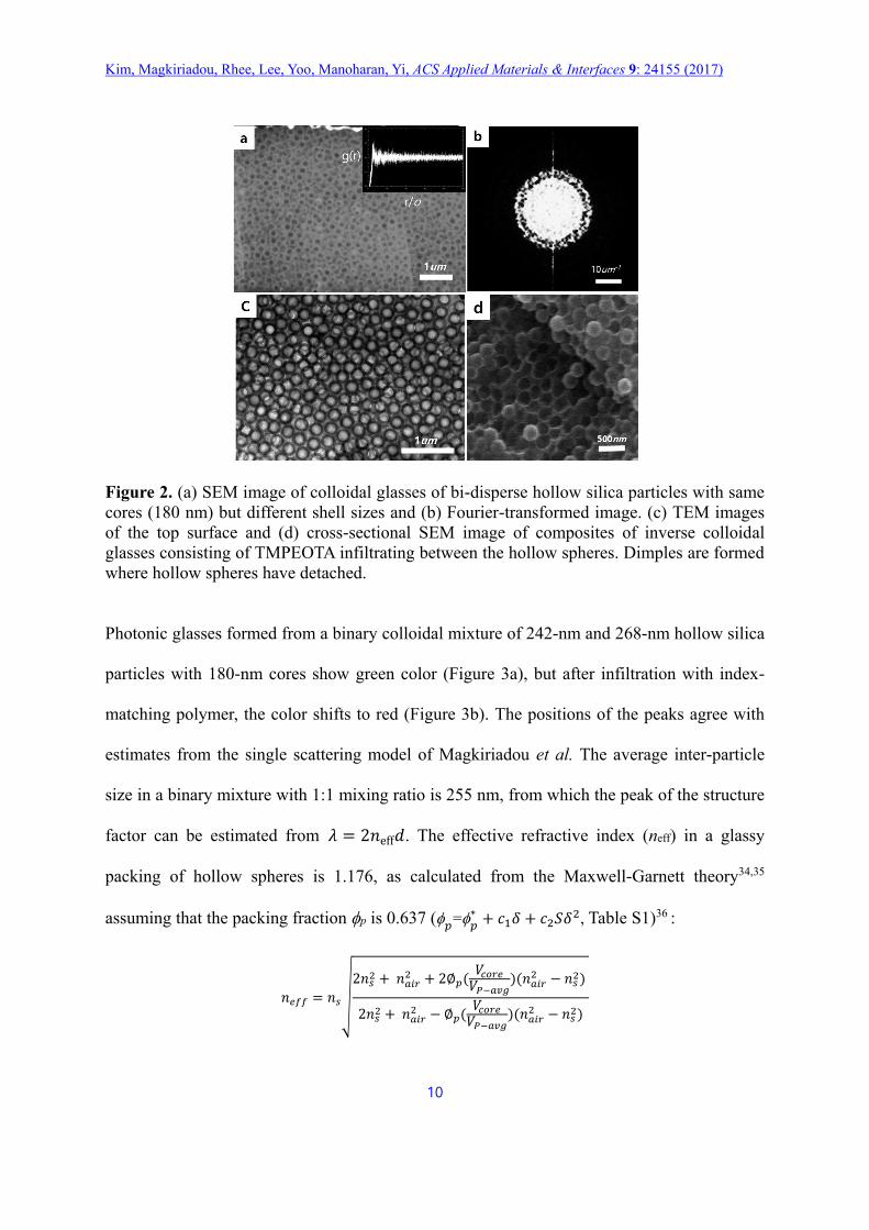
By evaporating the water from a binary colloidal mixture of 242-nm and 268-nm particles,
we assemble a disordered structure with a peak wavevector (q) around 24.4 m-1 (Figure 2b),
which is close to the calculated value (24.6 m-1) from Equation (1) by taking d as the
weight- average diameter (davg=ds×αs + dl×(1-αs), where αs is the number density of small
hollow silica spheres to large ones). Similarly, a disordered structure of 212-nm and 242-nm
hollow silica particles has a wavevector (q) around 27.9 m-1 (Figure S3b), which is close to
the calculated value (27.7 m-1).
We fill the interstices between the hollow spheres with index-matched photo-curable
monomer (trimethylolpropane ethoxylate triacrylate, TMPEOTA, n=1.46)33, which produces
an optically homogeneous matrix surrounding the disordered pores, as shown in the cross-
sectional TEM image of Figure 2c. By inspecting broken samples of composites of hollow
silica and TMPEOTA (see SEM image in Figure 2d), we infer that the internal structures are
disordered and that the TMPEOTA infiltrates the colloidal glasses completely.
Kim, Magkiriadou, Rhee, Lee, Yoo, Manoharan, Yi, ACS Applied Materials & Interfaces 9: 24155 (2017)
10
Figure 2. (a) SEM image of colloidal glasses of bi-disperse hollow silica particles with same
cores (180 nm) but different shell sizes and (b) Fourier-transformed image. (c) TEM images
of the top surface and (d) cross-sectional SEM image of composites of inverse colloidal
glasses consisting of TMPEOTA infiltrating between the hollow spheres. Dimples are formed
where hollow spheres have detached.
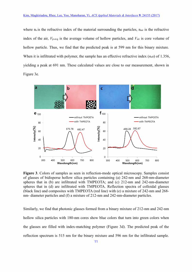
Photonic glasses formed from a binary colloidal mixture of 242-nm and 268-nm hollow silica
particles with 180-nm cores show green color (Figure 3a), but after infiltration with index-
matching polymer, the color shifts to red (Figure 3b). The positions of the peaks agree with
estimates from the single scattering model of Magkiriadou et al. The average inter-particle
size in a binary mixture with 1:1 mixing ratio is 255 nm, from which the peak of the structure
factor can be estimated from 𝜆 = 2𝑛eff𝑑. The effective refractive index (neff) in a glassy
packing of hollow spheres is 1.176, as calculated from the Maxwell-Garnett theory34,35
assuming that the packing fraction p is 0.637 (𝑝
=𝑝∗ + 𝑐1𝛿 + 𝑐2𝑆𝛿2, Table S1)36 :
𝑛𝑒𝑓𝑓 = 𝑛𝑠√
2𝑛𝑠2 + 𝑛𝑎𝑖𝑟
2 + 2∅𝑝(𝑉𝑐𝑜𝑟𝑒
𝑉𝑃−𝑎𝑣𝑔)(𝑛𝑎𝑖𝑟
2 − 𝑛𝑠2)
2𝑛𝑠2 + 𝑛𝑎𝑖𝑟
2 − ∅𝑝(𝑉𝑐𝑜𝑟𝑒
𝑉𝑃−𝑎𝑣𝑔)(𝑛𝑎𝑖𝑟
2 − 𝑛𝑠2)
Kim, Magkiriadou, Rhee, Lee, Yoo, Manoharan, Yi, ACS Applied Materials & Interfaces 9: 24155 (2017)
11
where ns is the refractive index of the material surrounding the particles, nair is the refractive
index of the air, Vp-avg is the average volume of hollow particles, and Vair is core volume of
hollow particle. Thus, we find that the predicted peak is at 599 nm for this binary mixture.
When it is infiltrated with polymer, the sample has an effective refractive index (neff) of 1.356,
yielding a peak at 691 nm. These calculated values are close to our measurement, shown in
Figure 3e.
Figure 3. Colors of samples as seen in reflection-mode optical microscopy. Samples consist
of glasses of bidisperse hollow silica particles containing (a) 242-nm and 268-nm-diameter
spheres that in (b) are infiltrated with TMPEOTA; and (c) 212-nm and 242-nm-diameter
spheres that in (d) are infiltrated with TMPEOTA. Reflection spectra of colloidal glasses
(black line) and composites with TMPEOTA (red line) with (e) a mixture of 242-nm and 268-
nm- diameter particles and (f) a mixture of 212-nm and 242-nm-diameter particles.
Similarly, we find that photonic glasses formed from a binary mixture of 212-nm and 242-nm
hollow silica particles with 180-nm cores show blue colors that turn into green colors when
the glasses are filled with index-matching polymer (Figure 3d). The predicted peak of the
reflection spectrum is 515 nm for the binary mixture and 596 nm for the infiltrated sample.
Kim, Magkiriadou, Rhee, Lee, Yoo, Manoharan, Yi, ACS Applied Materials & Interfaces 9: 24155 (2017)
12
These peak values are close to the 498 nm and 583 nm peaks that we observe in the reflection
spectrum shown in Figure 3f.
We note also that, in the angle-independent red sample shown in Figure 3b, there is no
secondary peak at short wavelengths, indicating that we have indeed successfully moved the
form factor peak into the UV. Furthermore, the saturation of the color, as determined from the
ratio of the peak reflectivity (at 682 nm, red line) to the reflectivity at short wavelengths in
Figure 3e, is 2.79 (Imax / Ibackground = 57.83/20.71). The saturation for colloidal glasses with a
mixture of 212-nm and 242-nm-diameter particles (Figure 3f, red line, 582 nm) is 2.61
(61.27/23.51). These saturation values are significantly higher than those previously reported
in the literature for systems with angle-independent structural red colors. 15, 16, 37
Angle-independent Colors from Inverse Photonic Glasses.
To test whether our samples do indeed show angle-independent structural color, we measure,
at various angles, the reflection spectrum of a binary mixture of 242-nm and 268-nm hollow
silica particles with 180-nm cores, infiltrated with index-matched resin. At 0˚ and 45˚ viewing
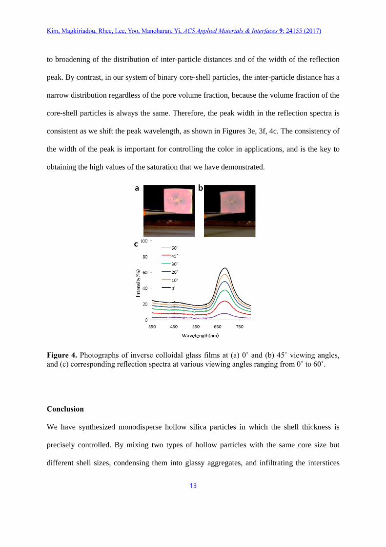
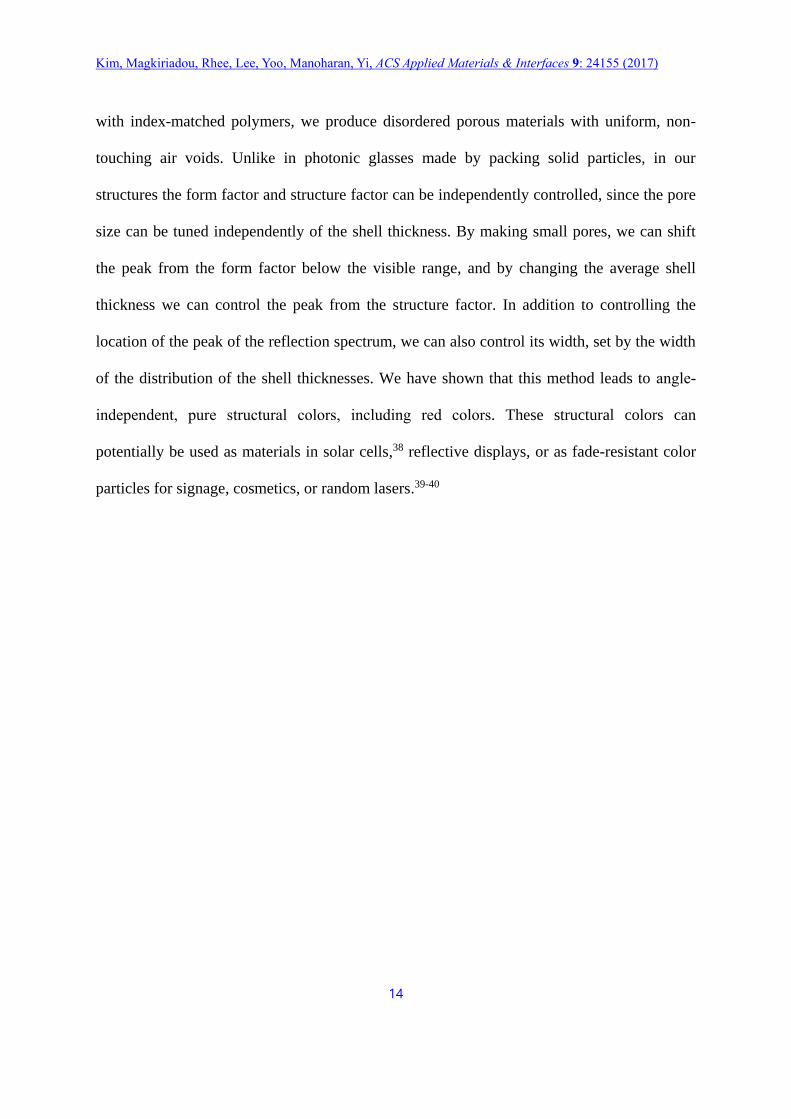
angles, we observe red colors, as shown in Figure 4a and 4b. The reflection spectra, shown in
Figure 4c, confirm that the peaks remain around 680 nm for viewing angles from 0˚ to 60˚. In
case of crystalline porous materials out of 268-nm hollow silica particles with 180-nm cores,
reflectivity in 0˚ viewing angle is relatively high but at other viewing angle, we can clearly
see angle-dependency of reflection color and intensity as shown in Figure S4.
In the “kinetic” approach to make glassy structures that we described earlier, relatively low
concentrations of particles are needed to obtain isotropic reflective red color, which can lead
Kim, Magkiriadou, Rhee, Lee, Yoo, Manoharan, Yi, ACS Applied Materials & Interfaces 9: 24155 (2017)
13
to broadening of the distribution of inter-particle distances and of the width of the reflection
peak. By contrast, in our system of binary core-shell particles, the inter-particle distance has a
narrow distribution regardless of the pore volume fraction, because the volume fraction of the
core-shell particles is always the same. Therefore, the peak width in the reflection spectra is
consistent as we shift the peak wavelength, as shown in Figures 3e, 3f, 4c. The consistency of
the width of the peak is important for controlling the color in applications, and is the key to
obtaining the high values of the saturation that we have demonstrated.
Figure 4. Photographs of inverse colloidal glass films at (a) 0˚ and (b) 45˚ viewing angles,
and (c) corresponding reflection spectra at various viewing angles ranging from 0˚ to 60˚.
Conclusion
We have synthesized monodisperse hollow silica particles in which the shell thickness is
precisely controlled. By mixing two types of hollow particles with the same core size but
different shell sizes, condensing them into glassy aggregates, and infiltrating the interstices
Kim, Magkiriadou, Rhee, Lee, Yoo, Manoharan, Yi, ACS Applied Materials & Interfaces 9: 24155 (2017)
14
with index-matched polymers, we produce disordered porous materials with uniform, non-
touching air voids. Unlike in photonic glasses made by packing solid particles, in our
structures the form factor and structure factor can be independently controlled, since the pore
size can be tuned independently of the shell thickness. By making small pores, we can shift
the peak from the form factor below the visible range, and by changing the average shell
thickness we can control the peak from the structure factor. In addition to controlling the
location of the peak of the reflection spectrum, we can also control its width, set by the width
of the distribution of the shell thicknesses. We have shown that this method leads to angle-
independent, pure structural colors, including red colors. These structural colors can
potentially be used as materials in solar cells,38 reflective displays, or as fade-resistant color
particles for signage, cosmetics, or random lasers.39-40
Kim, Magkiriadou, Rhee, Lee, Yoo, Manoharan, Yi, ACS Applied Materials & Interfaces 9: 24155 (2017)
15
Materials and Methods
Materials
Styrene (>97%, Sigma-Aldrich), potassium persulfate (KPS, Sigma-Aldrich), sodium styrene
sulfonate (NaSS, JUNSEI), sodium hydrogen carbonate, NaHCO3, JUNSEI), inhibitor
removers (Sigma Aldrich), vinyltrimethoxysilane (VTMS, 98%, Sigma-Aldrich), ammonium
hydroxide solution (NH4OH, 28–30%, Sigma-Aldrich), trimethylolpropane ethoxy triacrylate
(TMPEOTA, SK CYTEC), Darocur 1173 (SK CYTEC).
Synthesis of PS particles
Monodisperse polystyrene (PS) particles are synthesized by surfactant-free emulsion
polymerization. Typically, at first, the polymerization inhibitor (hydroquinone) or stabilizer
in the monomer are removed using an inhibitor remover packed column (Sigma-Aldrich).
Then, 50 g of styrene monomer are mixed at 900 rpm with 300 g of deionized water under
nitrogen gas. After 30 min stirring, 50 g of co-monomer solution (0.5 wt% of NaSS in water)
and 50 g of buffer solution (1 wt% of NaHCO3 in water) are added to the mixture of styrene
and water. Finally, 50 g of free-radical initiator solution (1 wt% of KPS in water) are added
after another 30 min stirring. The reaction proceeds at 80 oC for 12 h producing monodisperse
PS particles in water. After the complete reaction, un-reacted chemicals and secondary nuclei
(or small particles) are removed by several centrifugation/re-dispersion cycles.
Preparation of hollow silica particles
The PS colloidal particles are diluted to 1 wt% in DI water. Ammonium hydroxide solution
(28-30 wt%, 0.7 ml) is added to the PS particle suspension (10 ml) and mixed at 600 rpm for
Kim, Magkiriadou, Rhee, Lee, Yoo, Manoharan, Yi, ACS Applied Materials & Interfaces 9: 24155 (2017)
16
30 min. Organosilane with vinyl groups (VTMS, 0.4 - 2.0 ml) is mixed with DI water and
hydrolyzed by stirring at 900 rpm for 30 min. The PS particle suspension and hydrolyzed
VTMS solution are mixed and stirred at 600 rpm for 6 h at room temperature. After the sol-
gel coating of organosilica on PS particles, unreacted precursors are removed by a vacuum-
filtration process using a membrane filter with 200-nm pores (Millipore, JUNG-IL Science
Co., Ltd.). After washing by centrifugation and re-dispersion several times, the core-shell
particles are freeze-dried on a substrate and annealed at 600 oC for 6 h to remove the polymer
from the cores and organic chemicals from the shells and to densify the silica shell.
Fabrication of inverse photonic glasses
Inverse photonic glass structures are prepared by packing two different sizes of hollow silica
particles and infiltrating the interstices of the glass with polymer resin (TMPEOTA).
Typically, two hollow silica particle suspensions (30 wt%) 246 nm and 268 nm in diameter
are mixed by dispersing powders in water. Next, a CNT solution (0.1 wt%, 10 l) is added to
the hollow silica suspensions in water (1 ml).41 The mixture is dried at 40 oC for 12 h. After
the drying, TMPOETA (100 l) with photoinitiator (0.02 wt%, Darocur 1173) is added to the
dried colloidal glasses and then solidified by UV curing.
Characterization
Colloidal particles are observed under scanning electron microscopy (SEM, Hitachi, S-4300)
and transmission electron microscopy (TEM, JEOL LTD, JEM-2100F) to measure the size
and determine structure. Cross-sectional TEM samples of inverse photonic glass are prepared
using a focused ion beam machine (FIB, LYRA3 XMU, TESCAN). The color of photonic
colloidal glasses is observed under a reflection-mode optical microscope (Nikon, Ecipse 80i),
Kim, Magkiriadou, Rhee, Lee, Yoo, Manoharan, Yi, ACS Applied Materials & Interfaces 9: 24155 (2017)
17
and their reflectivity is measured using a fiber-coupled spectrometer (Ocean Optics Inc., BH-
2000-BAL).
Supporting Information
Additional data for SEM images of the hollow SiO2 particles with air core (Figure S1),
Histogram of size and shell thickness of hollow SiO2 particles (Figure S2), TEM image and
FFT image of colloidal glasses (Figure S3), Reflection spectra of crystalline porous materials
(Figure S4), Table of the theoretical equations for calculating the packing density value
(Table S1).
Acknowledgements
We acknowledge support from the National Research Foundation of Korea (NRF) (NRF-
2010-0029409 and NRF-2014M3A9B8023471), the Small and Medium Business
Administration of Korea (SMBA) under grant number 10050334 (World-Class 300 Project),
the Harvard MRSEC, funded by the National Science Foundation under grant number DMR-
1420570, and the Xerox University Affairs Committee.
Kim, Magkiriadou, Rhee, Lee, Yoo, Manoharan, Yi, ACS Applied Materials & Interfaces 9: 24155 (2017)
18
References
(1) Chen, L.; Shi, X.; Li, M.; Hu, J.; Sun, S.; Su, B.; Wen, Y.; Han, D.; Jiang, L.; Song, Y.
Bioinspired Photonic Structure by the Reflector Layer of Firefly Lantern for Highly
Efficient Chemiluminescence Sci. Rep. 2015, 5, 12965.
(2) Noh, H.; Liew, S. -F.; Saranathan, V.; Mochrie, S. G. J.; Prum, R. O.; Dufresne, E. R.;
Cao, H. How Noniridescent Colors are Generated by Quasi-Ordered Structures of Bird
Feathers Adv. Mater. 2010, 22 2871–2880.
(3) Saranathan, V., Forster, J. D.; Noh, H.; Liew, S.-F.; Mochrie, S. G. J.; Cao, H.;
Dufresne, E. R.; Prum, R. O. Structure and Optical Function of Amorphous Photonic
Nanostructures from Avian Feather Barbs: A Comparative Small Angle X-Ray
Scattering (SAXS) Analysis of 230 Bird Species J. R. Soc., Interface. 2012, 9, 2563-
2580.
(4) Shi, L.; Zhang, Y.; Dong, B.; Zhan, T.; Liu, X.; Zi, J. Amorphous Photonic Crystals with
Only Short-Range Order Adv. Mater. 2013, 25, 5314-5320.
(5) Ballato, J. Tailoring Visible Photonic Bandgaps Through Microstructural Order and
Coupled Material Effects in SiO2 Colloidal Crystals J. Opt. Soc. Am. B 2000, 17, 219–
225.
(6) Takeoka, Y. Angle-Independent Structural Coloured Amorphous Arrays J. Mater. Chem.
2012, 22, 23299-23309.
(7) García, P. D.; Sapienza, R.; Blanco, Á.; López, C. Photonic Glass: A Novel Random
Material for Light Adv. Mater. 2007, 19, 2597-2602.
(8) Espinha, A.; Ibisate, M.; Blanco, Á.; López, C. Engineering the Light-Transport Mean
Free Path in Silica Photonic Glasses Part. Part. Syst. Charact. 2016, 33, 352-357.
Kim, Magkiriadou, Rhee, Lee, Yoo, Manoharan, Yi, ACS Applied Materials & Interfaces 9: 24155 (2017)
19
(9) Forster, J. D.; Noh, H.; Liew, S. F.; Saranathan, V.; Schreck, C. F.; Yang, L.; Park, J. G.;
Prum, R. O.; Mochrie, S. G.; O'Hern, C. S. Biomimetic Isotropic Nanostructures for
Structural Coloration Adv. Mater. 2010, 22, 2939-2944.
(10) Magkiriadou, S.; Park, J.-G.; Kim, Y.-S.; Manoharan, V. N. Disordered Packings of
Core-Shell Particles with Angle-Independent Structural Colors Opt. Mater. Express.
2012, 2, 1343-1352.
(11) Bohren, C. F.; Huffman, D. R. Absorption and Scattering of Light by Small Particles;
John Wiley & Sons: New York, 1983
(12) Wang, F.; Zhang, X., Lin, Y.; Wang, L.; Zhu, J. Structural Coloration Pigments based on
Carbon Modified ZnS@SiO2 Nanospheres with Low-Angle Dependence, High Color
Saturation, and Enhanced Stability ACS Appl. Mater. Interfaces 2016, 8, 5009–5016.
(13) Iwata, M.; Teshima, M.; Seki, T.; Yoshioka, S.; Takeoka, Y. Bio-Inspired Bright
Structurally Colored Colloidal Amorphous Array Enhanced by Controlling Thickness
and Black Background Adv. Mater. 2017, DOI: 10.1002/adma.201605050.
(14) Katagiri, K.; Tanaka, Y.; Uemura, K.; Inumaru, K.; Seki, T.; Takeoka Y. Structural color
coating films composed of an amorphous array of colloidal particles via electrophoretic
deposition NPG Asia Materials 2017, 9, e355.
(15) Xiao, M.; Li, Y.; Allen, M. C.; Deheyn, D. D.; Yue, X.; Zhao, J. Gianneschi, N. C.;
Shawkey, M. D.; Dhinojwala, A. Bio-Inspired Structural Colors Produced via Self-
Assembly of Synthetic Melanin Nanoparticles ACS Nano, 2015, 9, 5454–5460.
(16) Zhang, Y.; Dong, B,; Chen, A.; Liu, X.; Shi, L.; Zi, J. Using Cuttlefish Ink as an Additive
to Produce Non-iridescent Structural Colors of High Color Visibility Adv. Mater. 2015,
27, 4719–4724.
(17) Kawamura, A.; Kohri, M.; Yoshioka, S.; Taniguchi, T.; Kishikawa, K. Structural Color
Kim, Magkiriadou, Rhee, Lee, Yoo, Manoharan, Yi, ACS Applied Materials & Interfaces 9: 24155 (2017)
20
Tuning: Mixing Melanin-Like Particles with Different Diameters to Create Neutral
Colors Langmuir 2017, 33, 3824–3830.
(18) Kawamura, A.; Kohri, M.; Morimoto, G.; Nannichi, Y.; Taniguchi, T.; Kishikawa, K.
Full-Color Biomimetic Photonic Materials with Iridescent and Non-Iridescent Structural
Colors Sci. Rep. 2016, 6, 33984.
(19) Kohri, M.; Nannichi, Y.; Taniguchi, T.; Kishikawa, K. Biomimetic non-iridescent
structural color materials from polydopamine black particles that mimic melanin
granules J. Mater. Chem. C 2015, 3, 720-724.
(20) Park, J. G.; Kim, S. H.; Magkiriadou, S.; Choi, T. M.; Kim, Y. S.; Manoharan, V. N. Full-
Spectrum Photonic Pigments with Non-iridescent Structural Colors through Colloidal
Assembly Angew. Chem., Int. Ed. 2014, 53, 2899-2903.
(21) Ueno, K.; Sano, Y.; Inaba, A.; Kondoh, M.; Watanabe, M. Soft Glassy Colloidal Arrays
in an Ionic Liquid: Colloidal Glass Transition, Ionic Transport, and Structural Color in
Relation to Microstructure J. Phys. Chem. B. 2010, 114, 13095-13103.
(22) Yang, X.; Ge, D.; Wu, G.; Liao, Z.; Yang, S. ACS Appl. Mater. Interfaces. 2016, 8,
16289-16295.
(23) Magkiriadou, S.; Park, J.-G.; Kim, Y.-S.; Manoharan, V. N. Absence of Red Structural
Color in Photonic Glasses, Bird Feathers, and Certain Beetles Phys. Rev. E 2014, 90,
062302.
(24) Lee, G. H.; Sim, J. Y.; Kim, S.-H. Polymeric Inverse Glasses for Development of
Noniridescent Structural Colors in Full Visible Range ACS Appl. Mater. Interfaces. 2016,
8, 12473-12480.
(25) Palberg, T.; Bartsch, E.; Beyer, R.; Hofmann, M.; Lorenz, N.; Marquis, J.; Niu, R.;
Okubo, T. To Make a Glass—Avoid the Crystal J. Stat. Mech.: Theory Exp. 2016,
Kim, Magkiriadou, Rhee, Lee, Yoo, Manoharan, Yi, ACS Applied Materials & Interfaces 9: 24155 (2017)
21
074007.
(26) Nandiyanto, A. B. D.; Akane, Y.; Ogi, T.; Okuyama, K. Mesopore-Free Hollow Silica
Particles with Controllable Diameter and Shell Thickness via Additive-Free Synthesis
Langmuir 2012, 28, 8616-8624.
(27) Ernawati, L.; Ogi, T.; Balgis, R.; Okuyama, K.; Stucki, M.; Hess, S. C.; Stark, W. J.
Hollow Silica as an Optically Transparent and Thermally Insulating Polymer Additive
Langmuir 2016, 32, 338-345.
(28) Chen, W.; Takai, C.; Khosroshahi, H. R.; Fuji, M.; Shirai, T. Surfactant-Free Fabrication
of SiO2-Coated Negatively Charged Polymer Beads and Monodisperse Hollow SiO2
Particles Colloids Surf., A. 2015, 481, 375–383.
(29) Zhang, L.; D’Acunzi, M.; Kappl, M.; Auernhammer, G. n. K.; Vollmer, D.; van Kats, C.
M.; van Blaaderen, A. Hollow Silica Spheres: Synthesis and Mechanical Properties
Langmuir 2009, 25, 2711-2717.
(30) Gao, T.; Jelle, B. P.; Sandberg, L. I. C.; Gustavsen, A. Monodisperse Hollow Silica
Nanospheres for Nano Insulation Materials: Synthesis, Characterization, and Life Cycle
Assessment ACS Appl. Mater. Interfaces. 2013, 5, 761-767.
(31) Rhee, D. K.; Jung, B.; Kim, Y. H.; Yeo, S. J.; Choi, S.-J.; Rauf, A.; Han, S.; Yi, G.-R.;
Lee, D.; Yoo, P. J. Particle-Nested Inverse Opal Structures as Hierarchically Structured
Large-Scale Membranes with Tunable Separation Properties ACS Appl. Mater.
Interfaces. 2014, 6, 9950-9954.
(32) Hunt, N.; Jardine, R.; Bartlett, P. Superlattice Formation in Mixtures of Hard-Sphere
Colloids Phys. Rev. E 2000, 62, 900-913.
(33) Widmann, J. f.; Davis, E. J. Photochemical Initiated Polymerization of Single
Microdroplets Colloid. Polym. Sci. 1996, 274, 525-531.
Kim, Magkiriadou, Rhee, Lee, Yoo, Manoharan, Yi, ACS Applied Materials & Interfaces 9: 24155 (2017)
22
(34) J. C. Maxwell Garnett, Colours in Metal Glasses and in Metallic Films Philos. Trans. R.
Soc. London, A 1904, 203, 385–420.
(35) Hutchinson, N. j .; Coquil, T.; Navid, A.; Pilon, L. Effective Optical Properties of Highly
Ordered Mesoporous Thin Films Thin Solid Films 2010, 518, 2141-2146.
(36) Desmond, K. W.; Weeks, E. R. Influence of Particle Size Distribution on Random Close
Packing of Spheres Phys. Rev. E 2014, 90, 022204.
(37) Ge, D.; Yang, L.; Wu, G.; Yang, S. Angle-Independent Colours from Spray Coated
Quasi-Amorphous Arrays of Nanoparticles: Combination of Constructive Interference
and Rayleigh Scattering J. Mater. Chem. C. 2014, 2, 4395-4400.
(38) Vynck, K.; Burresi, M.; Riboli, F.; Wiersma, D. S. Photon Management In Two-
Dimensional Disordered Media Nat. Mater. 2012, 11, 1017-1022.
(39) Wiersma, D. S. Optical Physics: Clear Directions for Random Lasers Nature 2016, 539,
360-361.
(40) Wiersma, D. S. The Physics and Applications of Random Lasers Nat. Phys. 2008, 4,
359-367.
(41) Wang, Y.; Iqbal, Z.; Mitra, S. Rapidly Functionalized, Water-Dispersed Carbon
Nanotubes at High Concentration J. Am. Chem. Soc. 2006, 128, 95-99.
Kim, Magkiriadou, Rhee, Lee, Yoo, Manoharan, Yi, ACS Applied Materials & Interfaces 9: 24155 (2017)
23
Supporting Information
Inverse Photonic Glasses by Packing Bi-disperse
Hollow Microspheres with Uniform Cores
Seung-Hyun Kim,† Sofia Magkiriadou,§ Do Kyung Rhee,† Doo-Sung Lee†, Pil J. Yoo,†,‡
Vinothan N. Manoharan,#,§ Gi-Ra Yi†,*
†School of Chemical Engineering and ‡Sungkyun Advanced Institute of Nano Technology
(SAINT), Sungkyunkwan University, Suwon 16419 Republic of Korea
§Department of Physics and #John A. Paulson School of Engineering and Applied Sciences,
Harvard University, Cambridge, USA
*E-mail: [email protected]
Kim, Magkiriadou, Rhee, Lee, Yoo, Manoharan, Yi, ACS Applied Materials & Interfaces 9: 24155 (2017)
24
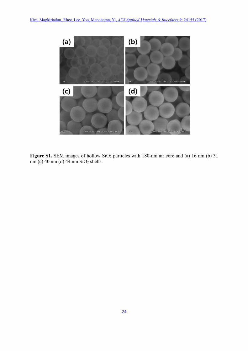
Figure S1. SEM images of hollow SiO2 particles with 180-nm air core and (a) 16 nm (b) 31
nm (c) 40 nm (d) 44 nm SiO2 shells.
Kim, Magkiriadou, Rhee, Lee, Yoo, Manoharan, Yi, ACS Applied Materials & Interfaces 9: 24155 (2017)
25
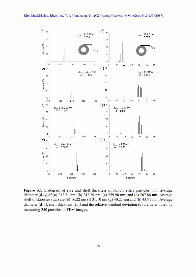
Figure S2. Histogram of size and shell thickness of hollow silica particles with average
diameter (davg) of (a) 212.31 nm, (b) 242.29 nm, (c) 259.90 nm, and (d) 267.86 nm. Average
shell thicknesses (tavg) are (e) 16.22 nm (f) 31.10 nm (g) 40.23 nm and (h) 43.91 nm. Average
diameter (davg), shell thickness (tavg) and the relative standard deviation (σ) are determined by
measuring 250 particles in TEM images.
Kim, Magkiriadou, Rhee, Lee, Yoo, Manoharan, Yi, ACS Applied Materials & Interfaces 9: 24155 (2017)
26
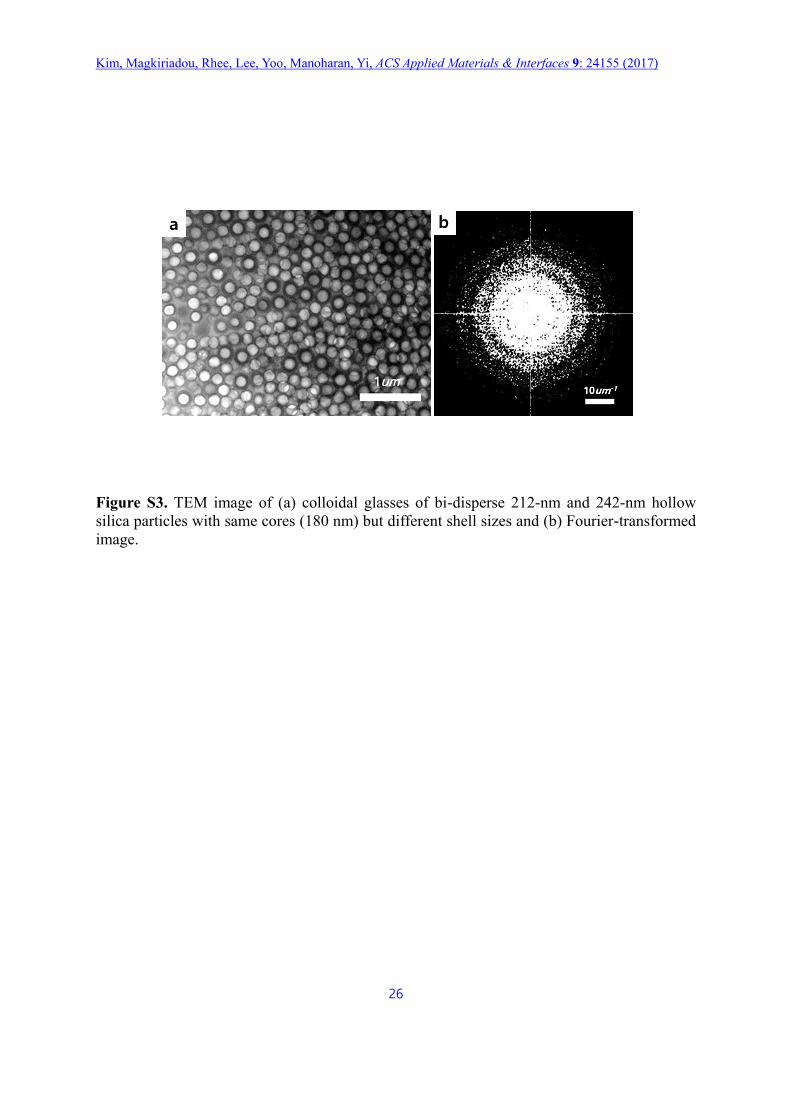
Figure S3. TEM image of (a) colloidal glasses of bi-disperse 212-nm and 242-nm hollow
silica particles with same cores (180 nm) but different shell sizes and (b) Fourier-transformed
image.
Kim, Magkiriadou, Rhee, Lee, Yoo, Manoharan, Yi, ACS Applied Materials & Interfaces 9: 24155 (2017)
27
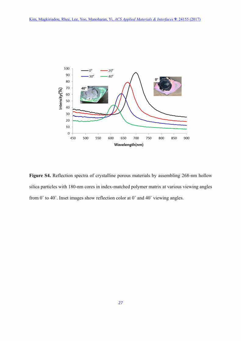
Figure S4. Reflection spectra of crystalline porous materials by assembling 268-nm hollow
silica particles with 180-nm cores in index-matched polymer matrix at various viewing angles
from 0˚ to 40˚. Inset images show reflection color at 0˚ and 40˚ viewing angles.
Kim, Magkiriadou, Rhee, Lee, Yoo, Manoharan, Yi, ACS Applied Materials & Interfaces 9: 24155 (2017)
28
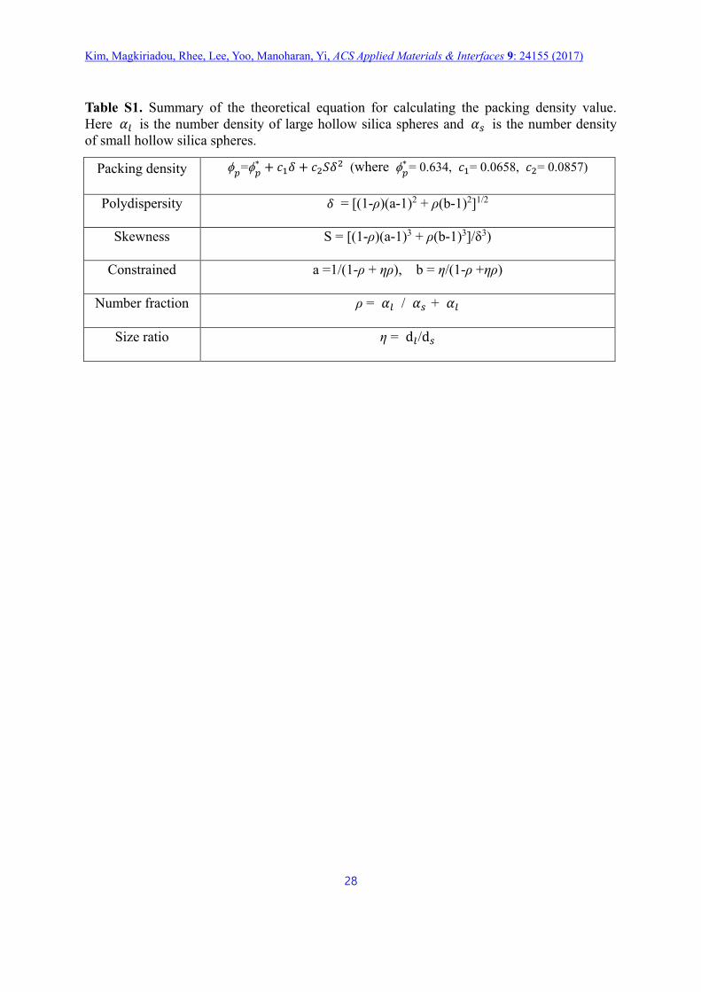
Table S1. Summary of the theoretical equation for calculating the packing density value.
Here 𝛼𝑙 is the number density of large hollow silica spheres and 𝛼𝑠 is the number density
of small hollow silica spheres.
Packing density 𝑝
=𝑝∗ + 𝑐1𝛿 + 𝑐2𝑆𝛿2 (where
𝑝∗
= 0.634, 𝑐1= 0.0658, 𝑐2= 0.0857)
Polydispersity 𝛿 = [(1-ρ)(a-1)2 + ρ(b-1)2]1/2
Skewness S = [(1-ρ)(a-1)3 + ρ(b-1)3]/δ3)
Constrained a =1/(1-ρ + ηρ), b = η/(1-ρ +ηρ)
Number fraction ρ = 𝛼𝑙 / 𝛼𝑠 + 𝛼𝑙
Size ratio η = d𝑙/d𝑠