acide debugging
TRANSCRIPT

SISTEMAS INFORMÁTICOS 2014/2015
FACULTAD DE INFORMÁTICA
UNIVERSIDAD COMPLUTENSE DE MADRID
ACIDE Debugging
Realizado por:
Sergio Domínguez Fuentes
Dirigido por:
Prof. Fernando Sáenz Pérez
Dpto. Ingeniería del Software e Inteligencia Artificial
Sistemas Informáticos 2014-2015 2
ÍNDICE DE CONTENIDOS
Índice de contenidos ........................................................................................................................ 2
1. Autorización ............................................................................................................................. 5
2. Resumen del proyecto .......................................................................................................... 6
3. Abstract ...................................................................................................................................... 8
4. Estado del arte ......................................................................................................................... 9
5. Estándares ...............................................................................................................................14
5.1. Control de versiones .................................................................................................. 14
5.2. Documentación ............................................................................................................ 15
5.3. Código fuente ................................................................................................................ 17
6. Gestión de la configuración ..............................................................................................21
7. Gestión de requisitos ..........................................................................................................22
7.1. Requisitos generales .................................................................................................. 22
7.2. Depuración .................................................................................................................... 23
7.2.1. Componentes de la aplicación ................................................................................ 23
7.2.2. Inicio de la aplicación ................................................................................................ 24
7.2.3. Panel Base de datos asertada .................................................................................. 24
7.2.3.1. Barra inferior ........................................................................................................... 24
7.2.3.2. Panel ............................................................................................................................ 25
7.2.4. Panel Traza Datalog .................................................................................................... 25
7.2.4.1. Barra Inferior ........................................................................................................... 26
7.2.4.2. Panel de traza........................................................................................................... 26
7.2.5. Panel Traza SQL ........................................................................................................... 27

Sistemas Informáticos 2014-2015 3
7.2.6. Panel Depurador SQL ................................................................................................ 27
8. Planificación ........................................................................................................................... 28
8.1. Release final .................................................................................................................. 28
9. Tareas realizadas ................................................................................................................. 30
9.1. Tareas generales ......................................................................................................... 30
9.2. PDG ................................................................................................................................... 31
9.3. Consola ........................................................................................................................... 31
9.4. Base de datos asertada ............................................................................................. 32
9.5. Bases de datos .............................................................................................................. 32
9.6. Editor de Textos .......................................................................................................... 33
9.7. Depuración .................................................................................................................... 33
9.7.1. Traza Datalog ............................................................................................................... 34
9.7.2. Traza SQL ....................................................................................................................... 34
9.7.3. Depurador SQL ............................................................................................................ 35
9.8. Actualización del manual de usuario .................................................................. 38
9.9. Objetivos cumplidos .................................................................................................. 39
9.9.1. Tareas de carácter general ............................................................................................... 39
9.9.2. PDG ............................................................................................................................................ 39
9.9.3. Depuración ............................................................................................................................. 39
9.9.4. Base de datos asertada ...................................................................................................... 39
9.9.5. Consola ..................................................................................................................................... 40
9.9.6. Editor de textos ..................................................................................................................... 40
9.9.7. Base de datos ......................................................................................................................... 40
Sistemas Informáticos 2014-2015 4
9.9.8. Ampliación del manual de usuario ............................................................................... 40
9.10. Objetivos no cumplidos ............................................................................................. 41
9.11. Conclusiones ................................................................................................................. 43
10. Posibles ampliaciones ....................................................................................................45
11. Lista de palabras claves .................................................................................................46
12. Bibliografía .........................................................................................................................47
13. Referencias .........................................................................................................................48
14. Información de contacto ...............................................................................................50
Apéndice: Manual de Usuario .....................................................................................................51
Sistemas Informáticos 2014-2015 6
2. RESUMEN DEL PROYECTO
Durante el presente curso académico, el equipo formado por Sergio Domínguez
Fuentes se ha encargado del desarrollo de “ACIDE: A Configurable IDE” para la
asignatura de Sistemas Informáticos.
ACIDE es un entorno de desarrollo integrado que puede ser fácilmente configurado
para casi cualquier intérprete, compilador o sistema de bases de datos.
Este proyecto no ha empezado este curso, si no que ha sido desarrollado en cursos
anteriores por diferentes grupos de alumnos en la asignatura Sistemas Informáticos:
El primer año en el que se llevó a cabo fue en el curso académico 2006-2007
por Diego Cardiel Freire, Juan José Ortiz Sánchez y Delfín Rupérez Cañas.
Durante el curso académico 2007-2008 el desarrollo fue continuado por
Miguel Martín Lázaro.
La siguiente iteración en el desarrollo de ACIDE fue en el curso 2010-2011
por Javier Salcedo Gómez.
Durante el curso académico 2012-2013 el desarrollo de ACIDE siguió en
manos de Pablo Gutiérrez García-Pardo, Elena Tejeiro Pérez de Ágreda y
Andrés Vicente del Cura.
Y en el curso académico 2013-2014 el desarrollo se realizó por Juan Jesús
Marqués Ortiz, Fernando Ordás Lorente y Semíramis Gutiérrez Quintana,
quienes dejaron ACIDE en el estado de desarrollo en el que nuestro grupo se
lo encontró.
Este proyecto fue dirigido siempre por Fernando Sáenz Pérez.
El objetivo al iniciar esta nueva etapa en ACIDE que comprende el presente curso
académico era mejorar la aplicación corrigiendo errores, mejorando funcionalidades y
añadiendo nuevas características.
Todos los detalles sobre el desarrollo en anteriores cursos académicos pueden
encontrarse en las memorias realizadas por los grupos antes mencionados, cuyas
memorias se encuentran listadas en la sección [1], [2], [3], [4] y [5] del capítulo
Referencias.

Sistemas Informáticos 2014-2015 7
La versión que heredamos del proyecto anterior (versión 0.16) tenía un código fuente
estandarizado y un comportamiento estable en cuanto a la gestión de proyectos,
creación y edición de ficheros de texto en diferentes lenguajes de programación,
conexión tanto con ODBC como con DES (Datalog Educational System) [6].
DES es una implementación basada en Prolog de un Sistema de bases de datos
deductivas.
Durante el presente curso académico hemos añadido funcionalidades a las ya
existentes como las ya comentadas antes y hemos desarrollado algunas nuevas o
pendientes de cursos anteriores.

Sistemas Informáticos 2014-2015 8
3. ABSTRACT
During the current academic year, the working group formed by Sergio Dominguez
Fuentes has taken the duty to develop “ACIDE: A Configurable IDE” as project of
“Computing Systems”.
ACIDE is an integrated development environment easily configurable for almost all
the interpreters, compilers or database systems.
This development is based in previous version of ACIDE; these versions were made by
some working groups as projects of “Computing Systems”:
The first time ACIDE was developed was during the academic year 2006-2007 by
Diego Cardiel Freire, Juan José Ortiz Sánchez and Delfín Rupérez Cañas.
After that, during the academic year 2007-2008 the development Miguel Martín
Lázaro continued with ACIDE.
The next phase was made by Javier Salcedo Gómez during the 2010-2011
academic year.
During the academic year 2012-2013, the development was implemented by
Pablo Gutiérrez García-Pardo, Elena Tejeiro Pérez de Ágreda and Andrés Vicente
del Cura
The last iteration was implemented by Juan Jesús Marqués Ortiz, Fernando Ordás
Lorente y Semíramis Gutiérrez Quintana during the 2013-2014 academic year.
This project was always managed by Fernando Sáenz Pérez.
The main goal in this new period was to improve the application by adding new
features and repairing or modifying old features.
Details about the development in previous academic years can be found in the
reports made by the aforementioned working groups. These reports are listed in section
[1], [2], [3], [4] and [5] in the References chapter.
We started from the version 0.16, it had a standardized source code and a stable
performance in terms of projects management, creating and editing text files in
different programming languages and connection with ODBC and DES (Datalog
Educational System) [6].
Sistemas Informáticos 2014-2015 9
4. ESTADO DEL ARTE
Para entender la evolución de ACIDE, primero vamos a mostrar un resumen sobre
el estado del arte en las publicaciones [1], [2] y [3], este resumen fue realizado en la
publicación [4] y muestra con detalle el estado de arte de ACIDE durante los tres
primeros cursos que estuvo en desarrollo. Una vez mostrado este resumen, se
describe el estado del arte en [4] y se finaliza el capítulo listando las referencias que
se han seguido durante el presente curso académico.
En [1] comenzó el desarrollo del proyecto ACIDE – A Configurable IDE, en el cual
se buscaba crear un IDE configurable para distintos lenguajes de programación y lo
bastante sencillo como para no asustar al usuario con demasiadas opciones y
complejidad. Entre los editores de texto consultados, se encuentran Crimson Editor
[7] y JEdit [8]. Ambos son editores de texto sencillos que permiten el resaltado de
palabras reservadas, seleccionadas de varios listados procedentes de diferentes
lenguajes. Además, JEdit permite configurar los menús, una idea muy atractiva para el
tipo de IDE que se perseguía desarrollar.
Sistemas Informáticos 2014-2015 10
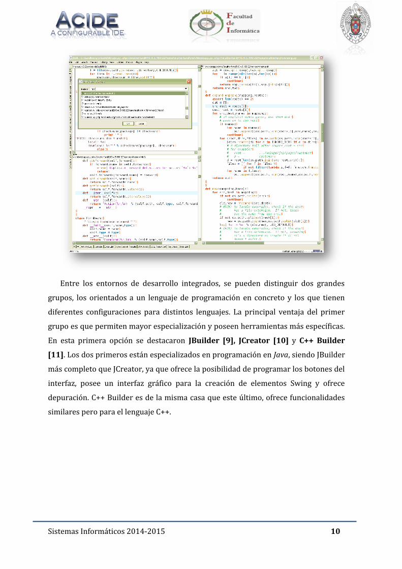
Entre los entornos de desarrollo integrados, se pueden distinguir dos grandes
grupos, los orientados a un lenguaje de programación en concreto y los que tienen
diferentes configuraciones para distintos lenguajes. La principal ventaja del primer
grupo es que permiten mayor especialización y poseen herramientas más específicas.
En esta primera opción se destacaron JBuilder [9], JCreator [10] y C++ Builder
[11]. Los dos primeros están especializados en programación en Java, siendo JBuilder
más completo que JCreator, ya que ofrece la posibilidad de programar los botones del
interfaz, posee un interfaz gráfico para la creación de elementos Swing y ofrece
depuración. C++ Builder es de la misma casa que este último, ofrece funcionalidades
similares pero para el lenguaje C++.
Sistemas Informáticos 2014-2015 11
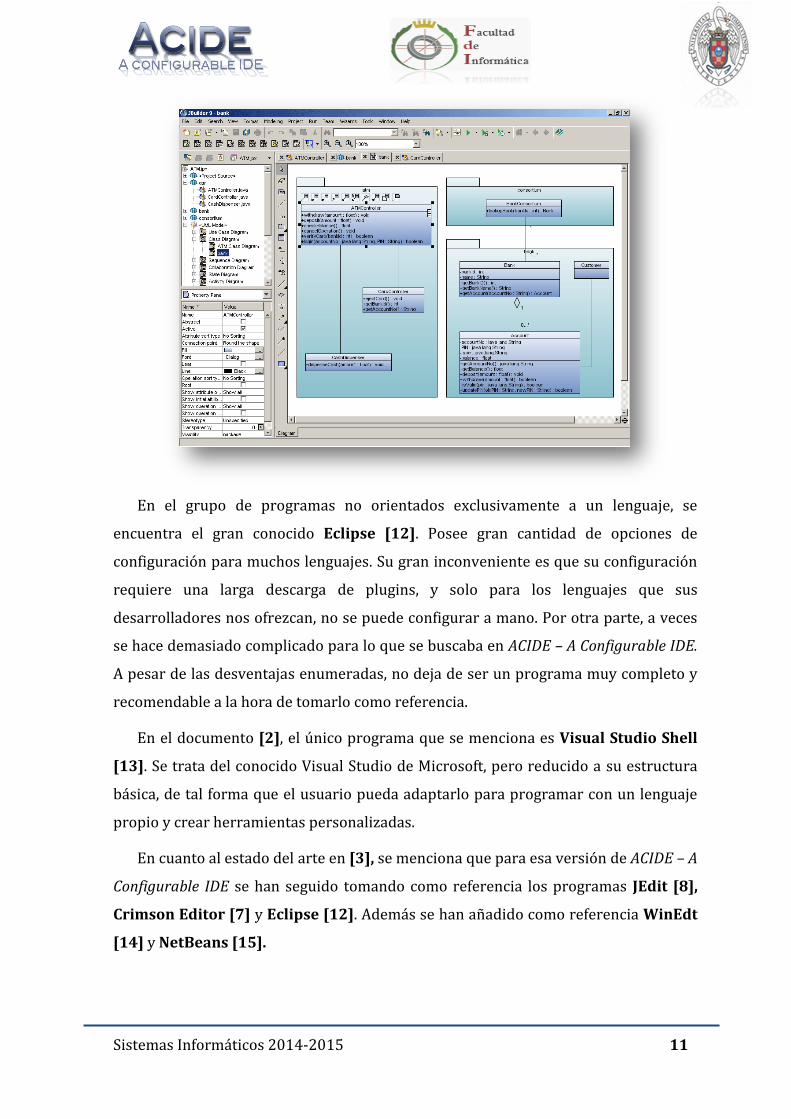
En el grupo de programas no orientados exclusivamente a un lenguaje, se
encuentra el gran conocido Eclipse [12]. Posee gran cantidad de opciones de
configuración para muchos lenguajes. Su gran inconveniente es que su configuración
requiere una larga descarga de plugins, y solo para los lenguajes que sus
desarrolladores nos ofrezcan, no se puede configurar a mano. Por otra parte, a veces
se hace demasiado complicado para lo que se buscaba en ACIDE – A Configurable IDE.
A pesar de las desventajas enumeradas, no deja de ser un programa muy completo y
recomendable a la hora de tomarlo como referencia.
En el documento [2], el único programa que se menciona es Visual Studio Shell
[13]. Se trata del conocido Visual Studio de Microsoft, pero reducido a su estructura
básica, de tal forma que el usuario pueda adaptarlo para programar con un lenguaje
propio y crear herramientas personalizadas.
En cuanto al estado del arte en [3], se menciona que para esa versión de ACIDE – A
Configurable IDE se han seguido tomando como referencia los programas JEdit [8],
Crimson Editor [7] y Eclipse [12]. Además se han añadido como referencia WinEdt
[14] y NetBeans [15].
Sistemas Informáticos 2014-2015 12
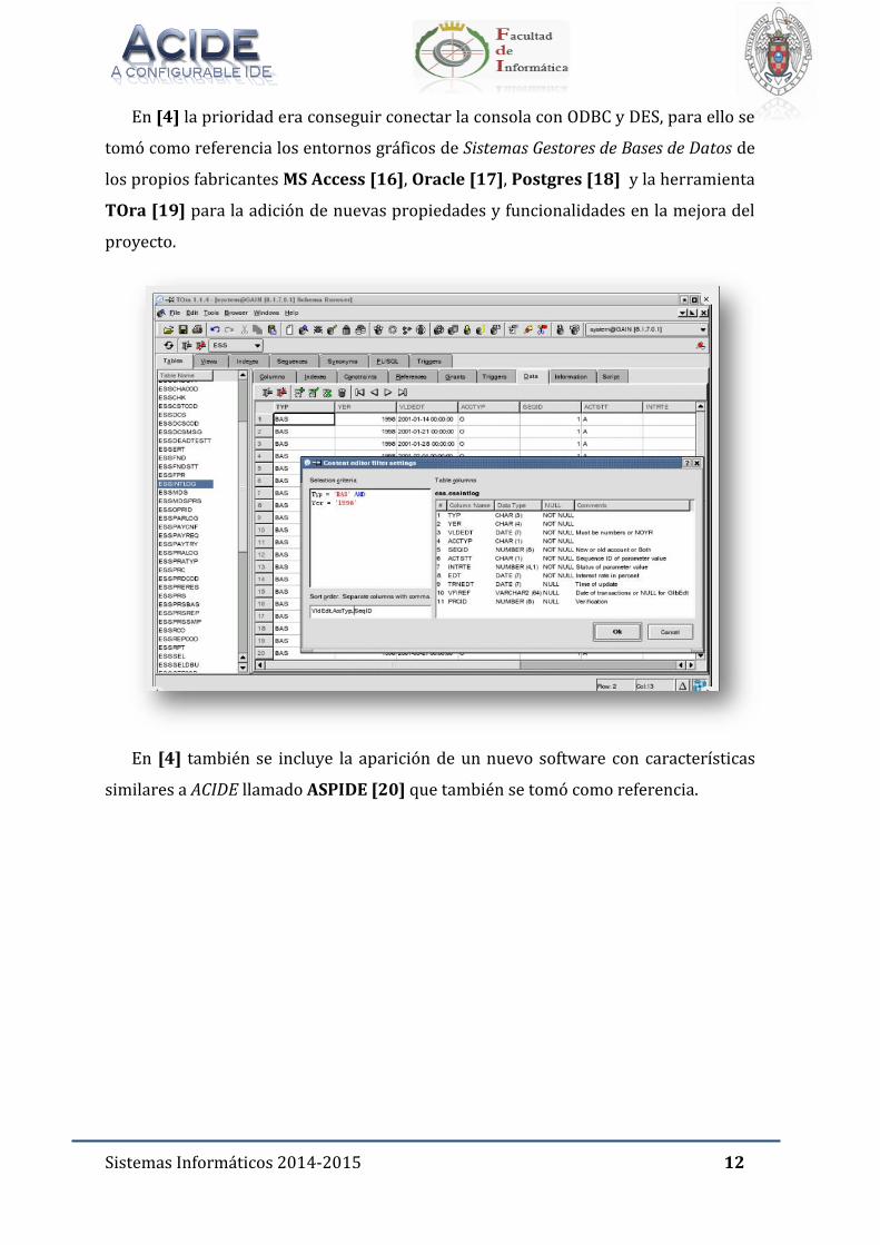
En [4] la prioridad era conseguir conectar la consola con ODBC y DES, para ello se
tomó como referencia los entornos gráficos de Sistemas Gestores de Bases de Datos de
los propios fabricantes MS Access [16], Oracle [17], Postgres [18] y la herramienta
TOra [19] para la adición de nuevas propiedades y funcionalidades en la mejora del
proyecto.
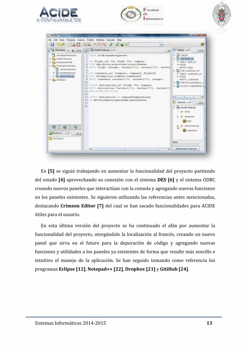
En [4] también se incluye la aparición de un nuevo software con características
similares a ACIDE llamado ASPIDE [20] que también se tomó como referencia.
Sistemas Informáticos 2014-2015 13
En [5] se siguió trabajando en aumentar la funcionalidad del proyecto partiendo
del estado [4] aprovechando su conexión con el sistema DES [6] y el sistema ODBC
creando nuevos paneles que interactúan con la consola y agregando nuevas funciones
en los paneles existentes. Se siguieron utilizando las referencias antes mencionadas,
destacando Crimson Editor [7] del cual se han sacado funcionalidades para ACIDE
útiles para el usuario.
En esta última versión del proyecto se ha continuado el afán por aumentar la
funcionalidad del proyecto, otorgándole la localización al francés, creando un nuevo
panel que sirva en el futuro para la depuración de código y agregando nuevas
funciones y utilidades a los paneles ya existentes de forma que resulte más sencillo e
intuitivo el manejo de la aplicación. Se han seguido tomando como referencia los
programas Eclipse [12], Notepad++ [22], Dropbox [21] y GitiHub [24].
Sistemas Informáticos 2014-2015 14
5. ESTÁNDARES
Cuando empezamos el proyecto, nos dimos cuenta que en los cursos anteriores,
los grupos que trabajaron en este proyecto habían invertido mucho tiempo y esfuerzo
en la estandarización del código fuente, los comentarios y la documentación. La
estandarización es muy importante en este proyecto por la naturaleza de código
abierto del mismo y ha sido una de nuestras prioridades a la hora de desarrollar
código, comentarlo y escribir la documentación. Esta prioridad ha venido impuesta
como un deseo del propio grupo de poder ofrecer un código lo más limpio y
entendible posible, tanto a futuros grupos de la asignatura Sistemas Informáticos,
como a toda aquella persona interesada en consultar el código que mueve a ACIDE.
A continuación se explican los estándares seguidos, puede consultarse más
información sobre los estándares seguidos en las memorias correspondientes a
ACIDE de años anteriores [1], [2], [3], [4] y [5].
5.1. CONTROL DE VERSIONES
Se ha llevado a cabo el control de versiones utilizando el cliente de versiones
GitHub [24].
Cada semana se ha entregado una nueva versión de la aplicación al director
Fernando Sáenz Pérez que consistía en un archivo ZIP y el documento TODO de tareas
a través de un enlace a una carpeta de entregas localizada en la aplicación de
almacenamiento en la nube Dropbox [21]. Dentro del archivo ZIP se encontraba el
ejecutable del proyecto. Cada archivo semanal seguía el siguiente convenio de
nomenclatura: “trunk_VersionApp_VersionEntrega_AAAAMMDD.zip” expresando
el año (AAAA), mes (MM) y día (DD) en forma numérica. De esta forma podíamos ir
almacenando todo el conjunto de versiones que se han ido entregando, y examinar la
evolución temporal del proyecto sin lugar a la confusión.
Sistemas Informáticos 2014-2015 15
5.2. DOCUMENTACIÓN
En la comunicación entre alumno y profesor durante la realización del proyecto,
se ha llevado a cabo el seguimiento del documento de tareas escritos periódicamente
y llamado “TODO_ACIDE.docx”. Este documento de tareas se enviaba semanalmente
junto a cada entregable, para su corrección y actualización, siendo entregada la nueva
versión del documento a los alumnos, con las tareas a corregir y realizar durante la
siguiente semana.
En cuanto al contenido, este documento se ha dividido en tres secciones
principales: Introducción, Tareas a Completar y Tareas Completadas. Estas categorías
se dividen a su vez en secciones basándose en las diversas funcionalidades de la
aplicación. Se establecen dos niveles de prioridad: tareas urgentes (en negrita) y
futuras funcionalidades.
Se ha creado una leyenda para mejorar la comprensión de estos documentos,
explicando el significado de cada color de fuente utilizado en la redacción de las
tareas:
Verde: Implementación completa y funcionamiento correcto.
Amarillo: Implementación en curso de desarrollo.
Rojo: Implementación no conseguida.
Negro: Comentarios del profesor.
Los estándares aplicados en estos documentos de tareas han sido los mismos
que en cursos anteriores y son los siguientes:
El estilo de texto Normal en el documento está compuesto por fuente Arial,
con tamaño 12pt, párrafo justificado, sangría de 0,5 cm en la primera línea,
color negro, interlineado de 1,5pt y espaciado anterior y posterior al
párrafo de 6pt.
El estilo de Título 1 está compuesto por fuente Calibri, con tamaño 26pt,
párrafo justificado, color “Azul Oscuro, Texto 2”, estilo Versales, espaciado
anterior 24pt y posterior 15pt al párrafo.
Sistemas Informáticos 2014-2015 16
El estilo de Título 2 está compuesto por fuente Calibri, con tamaño 16pt,
párrafo justificado, sangría francesa de 0,63 cm, color “Azul Oscuro, Texto
2”, estilo negrita y Versales, espaciado anterior 24pt y posterior 10pt al
párrafo.
El formato del pie de página está compuesto por fuente Arial, tamaño 12pt,
color negro. El pie de página contiene el texto “Sistemas Informáticos 2012-
2013” y a la derecha el número de página en estilo negrita. Una línea de
color azul separa el pie de página del resto de texto.
Las listas de enumeraciones se han realizado mediante la herramienta para
enumeraciones de Microsoft Word 2010.
El presente documento y el manual de usuario han seguido los mismos
estándares:
El estilo de texto Normal en el documento está compuesto por fuente
Cambria, con tamaño 12pt, párrafo justificado, sangría de 0,5 cm en la
primera línea, color negro, interlineado de 1,5pt y espaciado anterior y
posterior al párrafo de 6pt.
El estilo de Título 1 está compuesto por fuente Cambria, con tamaño 26pt,
párrafo justificado, color “Azul Oscuro, Texto 2”, estilo Versales, espaciado
anterior 24pt y posterior 15pt al párrafo.
El estilo de Título 2 está compuesto por fuente Cambria, con tamaño 16pt,
párrafo justificado, sangría francesa de 0,63 cm, color “Azul Oscuro, Texto
2”, estilo negrita y Versales, espaciado anterior 24pt y posterior 10pt al
párrafo.
El estilo de Título 3 está compuesto por fuente Cambria, con tamaño 14pt,
párrafo justificado, sangría francesa de 0,63 cm, color “Azul Oscuro, Texto
2”, estilo negrita y Versales, espaciado anterior 10pt.
El formato para escribir el código fuente en este documento está compuesto
por la fuente Courier New, con tamaño 11pt, alineación a la izquierda y
borde negro.
El formato del pie de página está compuesto por fuente Cambria, tamaño
12pt, color negro. El pie de página contiene el texto “Sistemas Informáticos
Sistemas Informáticos 2014-2015 17
2012-2013” y a la derecha el número de página en estilo negrita. Una línea
de color azul separa el pie de página del resto de texto.
El encabezado contiene las imágenes del logo de la aplicación, el símbolo de
la Facultad de Informática y el escudo de la Universidad Complutense de
Madrid.
Las listas de enumeraciones se han realizado mediante la herramienta para
enumeraciones de Microsoft Word 2010.
5.3. CÓDIGO FUENTE
Como se ha comentado anteriormente, se ha hecho un gran esfuerzo por
mantener el código en forma estandarizada. Se han seguido las normas establecidas
en cursos anteriores y que pasamos a listar a continuación:
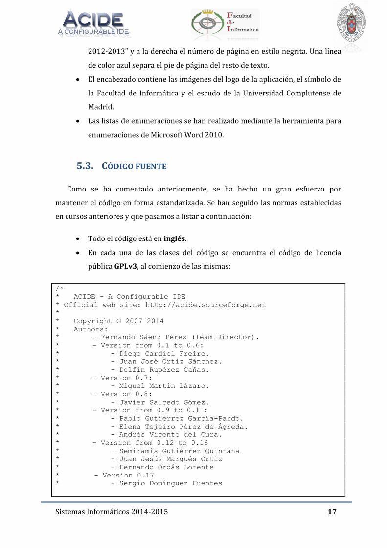
Todo el código está en inglés.
En cada una de las clases del código se encuentra el código de licencia
pública GPLv3, al comienzo de las mismas:
/*
* ACIDE – A Configurable IDE
* Official web site: http://acide.sourceforge.net
*
* Copyright © 2007-2014
* Authors:
* - Fernando Sáenz Pérez (Team Director).
* - Version from 0.1 to 0.6:
* - Diego Cardiel Freire.
* - Juan José Ortiz Sánchez.
* - Delfín Rupérez Cañas.
* - Version 0.7:
* - Miguel Martín Lázaro.
* - Version 0.8:
* - Javier Salcedo Gómez.
* - Version from 0.9 to 0.11:
* - Pablo Gutiérrez García-Pardo.
* - Elena Tejeiro Pérez de Ágreda.
* - Andrés Vicente del Cura.
* - Version from 0.12 to 0.16
* - Semíramis Gutiérrez Quintana
* - Juan Jesús Marqués Ortiz
* - Fernando Ordás Lorente
* - Version 0.17
* - Sergio Domínguez Fuentes
Sistemas Informáticos 2014-2015 18
*
* This program is free software: you can redistribute it and/or
* modify it under the terms of the GNU General Public License as
* published by the Free Software Foundation, either version 3 of
* the License, or (at your option) any later version.
*
* This program is distributed in the hope that it will be
* useful, but WITHOUT ANY WARRANTY; without even the implied
* warranty of MERCHANBILITY or FITNESS FOR A PARTICULAR PURPOSE.
* See the GNU General Public License for more details.
*
* You should have received a copy of the GNU General Public
* License along with this program. If not, see
* http://www.gnu.org/licenses/
*>
Comentarios Javadoc, simples y multilínea. Se ha procurado introducir
comentarios en cada una de las líneas de código para hacer más entendible
y amigable en su distribución el código.
// Updates the log
AcideLog.getLog().info(AcideLanguageManager.getInstance().
getLabels().getString(“s555”));
//Loads the ACIDE – A Configurable IDE workbench configuration
AcideWorkbenchConfiguration.getInstance().load();
Por cada clase Java en el código para los comentarios Javadoc se sigue el
siguiente formato:
/**
* Descripción de la clase.
*
* @version 0.11
* (@see <NombreDeClase/NombreDeInterfaz>)
*/
Las variables de cada clase van precedidas por ”_”:
private AcideFileMenu _fileMenu;
private boolean _fileInserted;
En todas las clases el nombre de la clase empieza por “Acide” seguido por
las palabras que definen la clase, empezando cada palabra por mayúscula,
siguiendo el estándar de Java:
public Class AcideMenuBar extends JMenuBar {…}
Sistemas Informáticos 2014-2015 19
En los nombres de los métodos, la primera palabra del nombre empieza por
minúscula y las palabras que siguen por mayúscula:
public void setTextOfMenuComponents() {…}
En las constantes de las clases, todo el nombre de la constante va en
mayúsculas, separando cada palabra con”_”.
public static final String DEFAULT_PATH = “./configuration/menu”;
En la configuración de los menús, las constantes que expresan los nombres
y los nombres de los iconos de cada opción del menú terminan con “NAME”
e “IMAGE” respectivamente:
public static final String COMPILER_NAME;
public static final ImageIcon COMPILER_IMAGE;
En clases que se refieren a ventanas de configuración, los nombres de las
variables terminan con el tipo de componente al que hacen referencia:
private JTabbedPane _tabbedPane;
private AcideFileMenuNewPanel _fileMenuPanel;
private JButton _acceptButton;
En todas las clases que corresponden a ventanas de configuración aparecen
los siguientes métodos:
//Builds the ACIDE – A Configurable IDE configuration window
//components
private void initComponents() {…}
//Adds the components to the ACIDE – A Configurable IDE to the
//configuration window
private void addComponents() {…}
//Sets the ACIDE – A Configurable IDE configuration window
//configuration
private void setWindowConfiguration() {…}
//Sets the listeners of the configuration window components.
private void setListeners() {…}
//Closes the window
private void closeWindow() {…}
En todas las clases que corresponden a la barra de menús y menús
contextuales aparecen obligatoriamente estos métodos:
Sistemas Informáticos 2014-2015 20
//Builds the ACIDE – A Configurable IDE configuration window
//components
private void buildComponents() {…}
//Adds the components to the ACIDE – A Configurable IDE to the
//configuration window
private void addComponents() {…}
//Sets the text of the ACIDE – A Configurable IDE class components
//with the labels in the selected language to display
private void setTextOfMenuComponents() {…}
//Updates the ACIDE – A Configurable IDE class components
//visibility with the menu configuration
private void updateComponentsVisibility() {…}
//Sets the listeners of the configuration window components.
private void setListeners() {…}
Sistemas Informáticos 2014-2015 21
6. GESTIÓN DE LA CONFIGURACIÓN
Todos los archivos del proyecto, tanto los archivos de documentación como los
archivos de código son objeto de control de la gestión de la configuración. Se ha
seguido con la configuración de la gestión descrita en las memorias [1], [2], [3], [4]
y [5].
Al elegir los nombres de documentos y de clases en el código fuente se utilizarán
siempre nombres que sean descriptivos de la información que contienen. Como se
ha comentado en la sección de estándares, para cada clase en el código fuente se
indica la versión a la que pertenece en el comentario previo al inicio de la clase. El
control de versiones en el código fuente se hace de forma automática gracias al uso
del cliente GitHub [24].
Por motivos de seguridad, todas las entregas debían de permitir el
funcionamiento de la aplicación y se han guardado como backup en la herramienta
Dropbox [21]. De esta manera en caso de fallo de los equipos, poseíamos copias de
seguridad de versiones anteriores a parte del control de versiones ya realizado por
GitHub.
Para la documentación, se guardaba la documentación de manera local en
Dropbox de modo que estuviera segura ante cualquier tipo de incidente. Los
documentos de tareas generados semanalmente, eran guardados y actualizados al
finalizar una tarea.
Hemos utilizado el siguiente software para la realización del proyecto:
Eclipse SDK versión 4.4.2 [12] para el desarrollo del código fuente en
lenguaje Java.
Microsoft Office 2010 para la documentación semanal y final del proyecto.
WinRar[25] para la generación de los archivos comprimidos.
Notepad++ [22] para la creación y edición de los archivos.
Dropbox [21] para guardar documentos generados durante el curso.
GitHub[24] como repositorio del código fuente y control de versiones.
Sistemas Informáticos 2014-2015 22
7. GESTIÓN DE REQUISITOS
Al principio se ha respetado la gestión de requisitos consultada en [5], sin
embargo, ésta se ha ido modificando conforme el proyecto se iba desarrollando y
surgían nuevas posibilidades.
Tras la primera toma de contacto, antes del comienzo del desarrollo del proyecto,
los requisitos fundamentales consistían en eliminar los errores existentes y aumentar
las funcionalidades requeridas.
Como se menciona en [3], [4] y [5], la estandarización y optimización del código
fuente se ha seguido cuidando. Al ser una aplicación de libre distribución, es
fundamental que el código publicado sea legible por terceros de manera que puedan
contribuir al desarrollo del mismo.
7.1. REQUISITOS GENERALES
En la aplicación se deben usar los nombres e identificadores exactamente
como se indica en este capítulo de requisitos. En particular se debe prestar
especial atención al uso de mayúsculas y minúsculas.
Todos los cuadros de diálogo con botón Cancelar (Cancel) deben aceptar
para la misma función la pulsación de la tecla Esc.
Al cerrar un cuadro de diálogo con el botón rojo del aspa se debe aplicar la
misma función del botón Cancelar (Cancel) o la función predeterminada
para cerrar el cuadro si no lo hubiere.
Todos los cuadros de diálogo deben aceptar la pulsación de la tecla ENTER
para realizar la acción predeterminada. Por ejemplo, la pulsación del botón
Aceptar (OK).
Todos los rótulos deben estar gestionados por la localización (dependiendo
del idioma seleccionado en la aplicación se mostrarán los rótulos en ese
idioma). En este documento solo se muestran los idiomas español e inglés,
pero puede haber más.
La aplicación debe ser ejecutable en distintas plataformas: Windows, Linux,
Mac OS.
Sistemas Informáticos 2014-2015 23
Todos los identificadores SQL que se envíen a DES deben aparecer
encerrados entre delimitadores.
El editor de texto que corresponda a la Vista Diseño de una vista debe estar
sincronizado con la selección en el árbol del Explorador de bases de datos. Es
decir, se debe seleccionar el nodo del árbol que corresponda cuando el
editor tenga el foco (y deseleccionar el nodo del Explorador de proyecto, sin
olvidar que se debe volver a seleccionar adecuadamente cuando se lleve el
foco a otro editor de archivo).
El cierre de cualquier ventana se podrá realizar con la combinación de
teclas de acceso directo Alt+F4.
Las ventanas deben ser redimensionables.
Todos los menús y barras de comando deben ser parametrizables por
archivo de configuración.
7.2. DEPURACIÓN
En este apartado se va a explicar detalladamente el documento “DES-Debug”. Este
documento describe los requisitos de la aplicación DES-ACIDE integrada en ACIDE: A
Configurable IDE referentes a la depuración SQL y Datalog y que ha centrado gran
parte de los esfuerzos de desarrollo durante el curso y por la que nuestro proyecto
lleva el nombre Debugging ACIDE.
A continuación se describirán los requisitos que se deben cumplir en el desarrollo
de la aplicación de depuración declarativa integrada en ACIDE.
7.2.1. COMPONENTES DE LA APLICACIÓN
La aplicación tiene dos partes principales:
Traza de consultas Datalog y vistas SQL
Depuración de consultas Datalog y vistas SQL
La traza permite, a partir de una consulta Datalog o vista SQL, inspeccionar su sub-
PDG (grafo de dependencias restringido transitivamente a las de un nodo en
Sistemas Informáticos 2014-2015 24
particular) examinando sus nodos. Para cada nodo se debe poder ver las tuplas
calculadas para él (en una ventana Data View) e iluminar las filas que contengan las
reglas o consultas de su definición. Este contenido puede estar repartido entre
distintos archivos de texto y de la base de datos asertada.
7.2.2. INICIO DE LA APLICACIÓN
Para acceder a la aplicación de depuración en ACIDE-DES, se deben añadir los
siguientes elementos nuevos al menú Ver:
Base de datos asertada
Traza
o Datalog
o SQL
Depuración
o Datalog
o SQL
7.2.3. PANEL BASE DE DATOS ASERTADA
Al seleccionar “Ver” (“View”) -> “Base de datos asertada” (”Asserted Database”) se
debe mostrar un panel con las reglas y hechos de la base de datos asertada (reglas
introducidas por consola en lugar de procesadas o consultadas de archivo) ordenados
por predicado (nombre/aridad: las reglas de los predicados de igual nombre pero
distinta aridad se muestran de menor a mayor aridad) y con una barra inferior con
distintos controles.
Al abrir este panel se deben rellenar automáticamente sus contenidos como se
indica en el siguiente apartado.
7.2.3.1. BARRA INFERIOR
La barra inferior contiene los siguientes controles y etiquetas:
“R”<<Button>> “C”<<Button>> Filtro<<CheckBox>> Núm.<<Label>>
Sistemas Informáticos 2014-2015 25
Botón “R”(“Refresh”):
o Uso: permite actualizar los contenidos del panel de la base de datos
asertada.
o Pulsación: Actualización del panel de la base de datos asertada.
o Atajo: F5.
o Comandos TAPI:
Para obtener los predicados: /tapi /pdg
Para obtener las reglas de la definición de cada predicado:
/tapi /listing_asserted Name/Arity. Se debe emitir este
comando por cada uno de los nodos del PDG, anotando
internamente las reglas del panel que correspondan a cada
predicado.
Botón “C” (“Clear”):
o Uso: permite quitar el resalte.
o Pulsación: Quitar resalte.
La casilla de verificación Filtro, si está activada, muestra solo las reglas del
nodo seleccionado. Si está desactivada, muestra todas las reglas de la base
de datos asertada.
Etiqueta “Núm”:
o Uso: Muestra el número de reglas observando el número.
7.2.3.2. PANEL
El panel muestra cada regla asertada, separándolas entre sí visualmente. Se puede
resaltar un conjunto de líneas (consecutivas) como resultado de una interacción con
el panel de depuración o de traza.
7.2.4. PANEL TRAZA DATALOG
Al seleccionar “Vista” (“View”) -> “Traza” (“Trace”) -> “Datalog” se muestra el panel
“Traza Datalog” (“Trace Datalog”), que mostrará el sub-PDG restringido a una
consulta, y una barra inferior con distintos controles. El panel no muestra nada hasta
que no se haya introducido la consulta.
Sistemas Informáticos 2014-2015 26
7.2.4.1. BARRA INFERIOR
La barra inferior contiene los siguientes controles y etiquetas, además de los que
ya contenía la barra inferior del panel PDG:
“Consulta Datalog:” (“Datalog Query:”) <<TextBox>> “R”<<Button>>
“<-”<<Button>> “->”<<Button>> “Mostrar reglas” (“Show rules”)<<CheckBox>>
El cuadro de texto “Consulta Datalog:” admite escribir una consulta Datalog
en una sola línea sobre la que se efectuará la traza.
Intro: Reinicio de la traza. Se selecciona automáticamente el primer nodo en
el recorrido.
Comando TAPI: /tapi /trace_datalog Query, donde “Query” es el valor
introducido en el cuadro de texto. Devuelve el recorrido de nodos.
El botón “R” permite reiniciar la traza (similar a un botón “Actualizar”). Este
comportamiento reemplaza el comportamiento del botón “R” del panel PDG
del que hereda.
Comando TAPI: /tapi /trace_datalog Query, donde “Query” es el valor
introducido en el cuadro de texto.
El botón flecha a la izquierda “<-” permite seleccionar el nodo anterior del
sub-PDG en el orden de recorrido que devuelve el comando /tapi
/trace_datalog Query. Si se pulsa sobre el nodo que es el primero en este
orden, se seleccionará el último.
El botón flecha a la derecha “->” hace lo propio con el nodo posterior. Si se
pulsa sobre el nodo que es el último en el orden, se seleccionará el primero.
La casilla de verificación “Mostrar reglas”, si está activada, provoca que se
resalte automáticamente las reglas en los editores y el panel de la base de
datos asertada.
7.2.4.2. PANEL DE TRAZA
El panel de traza es similar al panel del PDG al que se le añaden nuevas
funcionalidades:
Sistemas Informáticos 2014-2015 27
Selección de un nodo (Clic sobre el nodo): seleccionar las reglas de su
predicado, que pueden estar repartidas entre un editor de archivo y el panel
“Asserted Database”. El comando /tapi /list_sources Name/Arity lista los
archivos y números de línea para las reglas consultadas, y el momento de
las asertadas. Para saber en qué editor y líneas se encuentran las
consultadas para seleccionarlas se hace mediante este comando. Para saber
las reglas a seleccionar en el panel de la base de datos asertada se hace uso
de la información que se obtuvo para construir sus contenidos.
Doble clic sobre un nodo: abrir el “Data View” del nodo. El comando /tapi
/list_et Name/Arity devuelve los contenidos de la tabla de extensión para
las respuestas calculadas para el nodo Name/Arity.
7.2.5. PANEL TRAZA SQL
Es equivalente al panel “Traza Datalog”. Al igual que este, no se rellena hasta que
no se elija la vista a trazar. Como diferencia, en lugar de seleccionar las reglas que
definen un predicado, se selecciona la definición de la vista (consulta SQL de la
instrucción de creación de vista).
7.2.6. PANEL DEPURADOR SQL
Es equivalente al panel “Traza SQL” y al igual que los anteriores, no se rellena hasta
que no se elija la vista a trazar. Lo que caracteriza a este panel, es que permite abrir
un menú desplegable en cada nodo para poder depurar de una forma más eficiente
las vistas, pudiendo modificar el color de los nodos entre otras opciones. El objetivo
final de este panel será identificar los nodos en error y marcarlos en rojo de forma
automática, para así identificarlos directamente.
Hasta el momento, es el propio usuario quien puede marcar los nodos como
“válido”, “no válido” o “desconocido”.
Sistemas Informáticos 2014-2015 28
8. PLANIFICACIÓN
La planificación se ha llevado a cabo en iteraciones semanales. Un día a la semana
me he reunido con el director Fernando Sáenz Pérez. Durante estas reuniones se han
evaluado los progresos y el trabajo realizado durante esa semana y se han propuesto
tareas y objetivos para la semana siguiente.
Para llevar a cabo esta planificación, en cada reunión disponíamos de un
documento de tareas, donde se indicaban las tareas realizadas, las tareas que habían
supuesto alguna dificultad, o las dudas relativas a una tarea en concreto y la
aplicación con el trabajo de esa semana. En la reunión se repasaba el documento,
realizando pruebas unitarias sobre las tareas realizadas y resolviendo las dudas que
habían surgido durante la semana. Una vez se había revisado el documento y según el
resultado de la revisión, se planificaban las tareas de la semana siguiente, intentando
realizar las planificaciones en función de la dificultad y la prioridad.
Durante el ciclo de vida del desarrollo se pueden observar las diferentes
modificaciones y mejoras recogidas todas ellas en un único hito importante que
corresponde a una nueva publicación de la aplicación.
8.1. RELEASE FINAL
El desarrollo de esta release queda delimitado entre el inicio del proyecto y el
final del curso académico, correspondiendo con la entrega final de un IDE estable y
distribuible.
Durante todo este periodo, inicialmente la prioridad fue familiarizarse con la
aplicación, configurar el entorno de trabajo y buscar y resolver posibles bugs que
pudieran haber sido arrastrados de años anteriores y que no hubieran sido
detectados antes.
Una vez que tuve el entorno de trabajo preparado y configurado se dispuso a la
resolución de las primeras tareas.
Posteriormente, una vez la aplicación ya comenzaba a ser más conocida y tras
realizar tareas como la localización al francés, la modificación que permitía la

Sistemas Informáticos 2014-2015 29
apertura de múltiples documentos nuevos simultáneamente o la modificación de la
barra inferior de la aplicación para permitir su copiado, se comenzó con las
modificaciones de funcionalidad más específicos y la corrección de bugs detectados.
Una de las mejoras introducidas más importantes fue la creación de la nueva
pestaña de depuración SQL en el panel de Depuración para permitir la interacción
directa de la vista con el usuario ayudando a éste último a depurar posibles errores
en la vista ayudado de un código de colores individual para cada nodo.
Con la finalización de esta iteración se publicó la versión 0.17 de la aplicación,
con las nuevas funcionalidades sobre las que se había trabajado operativas.
Sistemas Informáticos 2014-2015 30
9. TAREAS REALIZADAS
A continuación se describen en detalle las tareas realizadas separadas en los
diferentes módulos de la aplicación:
9.1. TAREAS GENERALES
En esta sección se recogen las tareas que por su naturaleza no pueden englobarse en
los puntos específicos de cada panel y que afectan de una forma u otra al conjunto de
la aplicación:
Localización al Francés. Dado la gran utilización de esta aplicación en
diferentes países, se ha realizado la localización de toda la aplicación al
francés, permitiendo ya trabajar con la aplicación en tres idiomas y facilitando
su manejo a cada vez un mayor número de usuarios.
Barra de estado copiable. A fin de permitir copiar la ruta y/o el nombre del
archivo actual de trabajo (pero sin permitir su edición), se modificaron las
características de la barra de estado inferior dónde se indican dichos datos.
Cambio de ruta de la apertura de archivos. Para facilitar hallar los archivos a
abrir, si no hay un proyecto cargado y se intenta abrir un archivo, el directorio
para seleccionarlo se ha cambiado por el de inicio de la aplicación ACIDE, en
lugar de Mis Documentos como estaba anteriormente.
Mantenimiento de la estandarización, como se ha indicado en la sección
Estándares, el proyecto fue heredado con una serie de estándares que se han
seguido usando, por lo que ha sido una tarea constante la continuación de los
estándares recibidos, para poder tener tanto un código como una
documentación lo más homogénea y limpia.
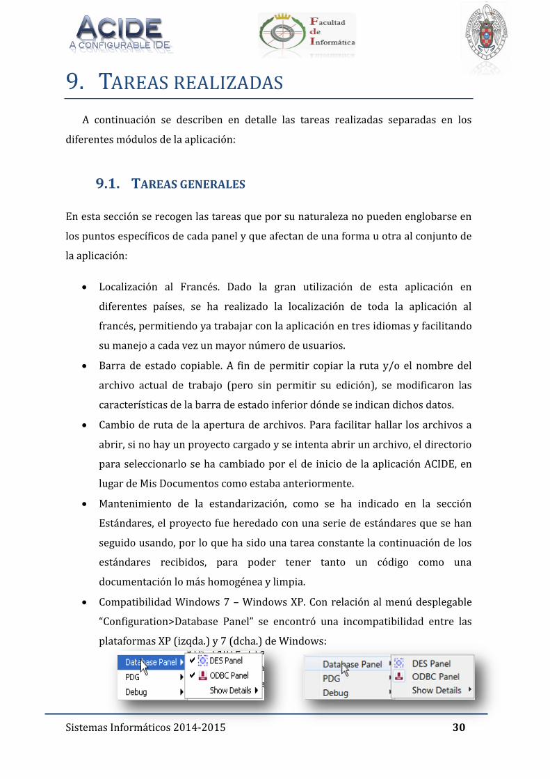
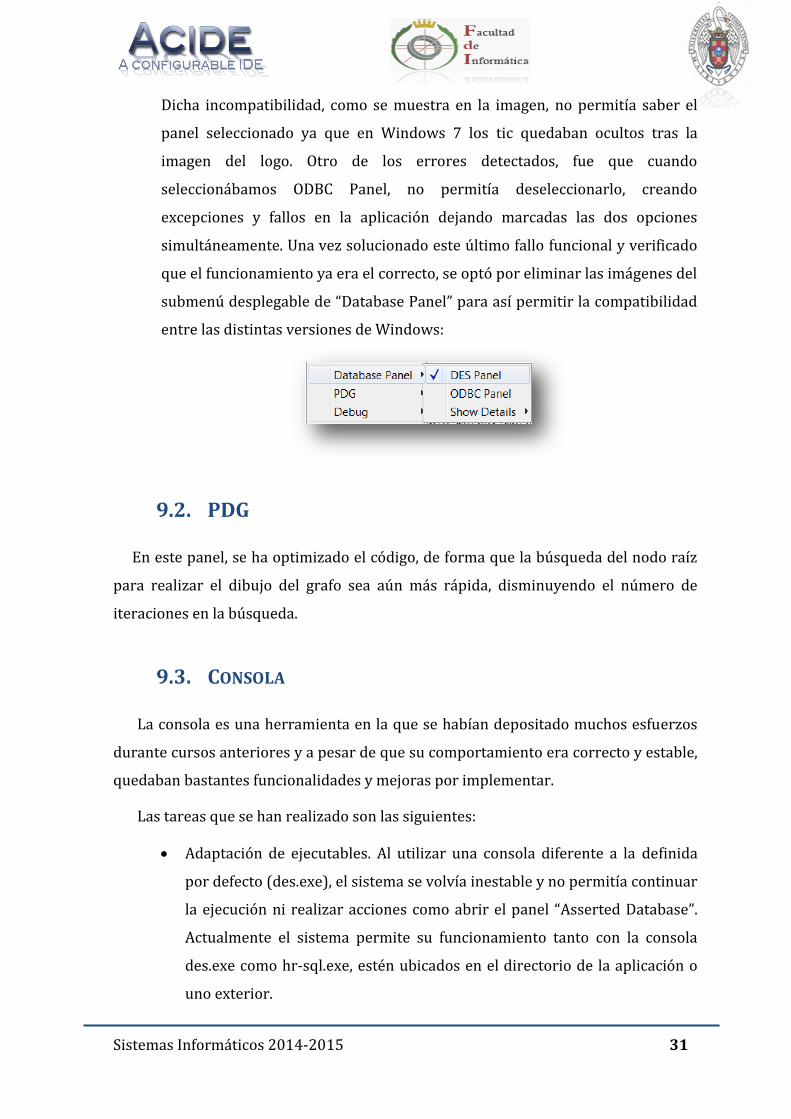
Compatibilidad Windows 7 – Windows XP. Con relación al menú desplegable
“Configuration>Database Panel” se encontró una incompatibilidad entre las
plataformas XP (izqda.) y 7 (dcha.) de Windows:
Sistemas Informáticos 2014-2015 31
Dicha incompatibilidad, como se muestra en la imagen, no permitía saber el
panel seleccionado ya que en Windows 7 los tic quedaban ocultos tras la
imagen del logo. Otro de los errores detectados, fue que cuando
seleccionábamos ODBC Panel, no permitía deseleccionarlo, creando
excepciones y fallos en la aplicación dejando marcadas las dos opciones
simultáneamente. Una vez solucionado este último fallo funcional y verificado
que el funcionamiento ya era el correcto, se optó por eliminar las imágenes del
submenú desplegable de “Database Panel” para así permitir la compatibilidad
entre las distintas versiones de Windows:
9.2. PDG
En este panel, se ha optimizado el código, de forma que la búsqueda del nodo raíz
para realizar el dibujo del grafo sea aún más rápida, disminuyendo el número de
iteraciones en la búsqueda.
9.3. CONSOLA
La consola es una herramienta en la que se habían depositado muchos esfuerzos
durante cursos anteriores y a pesar de que su comportamiento era correcto y estable,
quedaban bastantes funcionalidades y mejoras por implementar.
Las tareas que se han realizado son las siguientes:
Adaptación de ejecutables. Al utilizar una consola diferente a la definida
por defecto (des.exe), el sistema se volvía inestable y no permitía continuar
la ejecución ni realizar acciones como abrir el panel “Asserted Database”.
Actualmente el sistema permite su funcionamiento tanto con la consola
des.exe como hr-sql.exe, estén ubicados en el directorio de la aplicación o
uno exterior.

Sistemas Informáticos 2014-2015 32
Múltiples cambios de consola En versiones anteriores sólo se permitía un
cambio de consola; actualmente se puede cambiar varias veces de consola
sin lugar a error.
9.4. BASE DE DATOS ASERTADA
En el panel de Base de Datos Asertada, se han incluido los tooltips siguientes a los
botones:
Icono actualizar: Refresh
Icono C: Clear
9.5. BASES DE DATOS
En esta nueva versión el panel de Bases de datos ha experimentado cambios y
mejoras tanto en su interfaz gráfica como en su funcionalidad. Además, se han
corregido ciertos bugs de versiones anteriores que afectaban al buen funcionamiento
del panel.
Si bien el panel conserva la estructura y representación original, los cambios más
significativos se detallan a continuación:
Mejora de la comunicación entre consola y panel Database. La
comunicación entre el panel Database y DES no parecía hacerse
correctamente. Se podía probar cambiando el prompt con "/prompt plain”,
actualizando el nodo Databases y viendo como aparecía el prompt como
hijo de "Databases":
Actualmente, independientemente del prompt en la consola, el panel de
Database muestra correctamente los valores de base de datos.
Sistemas Informáticos 2014-2015 33
Reapertura del panel. Una vez se cerraba el panel, de manera puntual, no
era posible volver a abrir el panel de nuevo. Este error ya ha sido corregido
y el panel puede cerrarse y abrirse sin problemas de manera repetida.
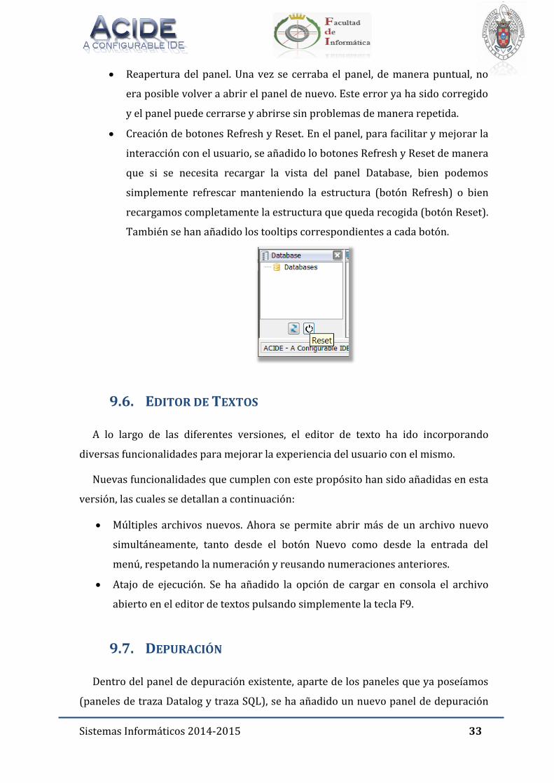
Creación de botones Refresh y Reset. En el panel, para facilitar y mejorar la
interacción con el usuario, se añadido lo botones Refresh y Reset de manera
que si se necesita recargar la vista del panel Database, bien podemos
simplemente refrescar manteniendo la estructura (botón Refresh) o bien
recargamos completamente la estructura que queda recogida (botón Reset).
También se han añadido los tooltips correspondientes a cada botón.
9.6. EDITOR DE TEXTOS
A lo largo de las diferentes versiones, el editor de texto ha ido incorporando
diversas funcionalidades para mejorar la experiencia del usuario con el mismo.
Nuevas funcionalidades que cumplen con este propósito han sido añadidas en esta
versión, las cuales se detallan a continuación:
Múltiples archivos nuevos. Ahora se permite abrir más de un archivo nuevo
simultáneamente, tanto desde el botón Nuevo como desde la entrada del
menú, respetando la numeración y reusando numeraciones anteriores.
Atajo de ejecución. Se ha añadido la opción de cargar en consola el archivo
abierto en el editor de textos pulsando simplemente la tecla F9.
9.7. DEPURACIÓN
Dentro del panel de depuración existente, aparte de los paneles que ya poseíamos
(paneles de traza Datalog y traza SQL), se ha añadido un nuevo panel de depuración
Sistemas Informáticos 2014-2015 34
(Debug SQL) en el cual se muestra un grafo de dependencias con apariencia similar al
grafo de dependencias del panel de traza. Para poder mostrar todos los paneles de
traza sin añadir más carga de paneles a la apariencia de la interfaz, se ha respetado el
método de representación actual, mostrándose mediante un mecanismo de pestañas
seleccionables.
9.7.1. TRAZA DATALOG
En el panel de traza Datalog se muestra el grafo de dependencias restringido a una
consulta Datalog introducida por el usuario. Las modificaciones en dicho panel se
muestran a continuación:
Modificación del botón Refresh. A fin de facilitar el manejo del usuario y
evitar excepciones de código innecesarias, se ha decidido desactivar desde
un inicio la pulsación del botón Refresh y reactivarlo una vez se ha cargado
alguno de los archivos abiertos. También se ha creado el tooltip específico
del botón.
Desactivación casilla Reglas. En la pestaña Trace Datalog se ha optado por
desactivar por defecto la pestaña de Reglas a fin de optimizar el tiempo de
carga inicial de la aplicación.
Modificación de la ventana Query. Se ha cambiado el panel Query de forma
que solo se admita una línea de texto como consulta y que dicha consulta se
pueda ejecutar al pulsar directamente el botón Intro.
También se ha revisado la traza de Datalog de forma que nos asegurásemos
que el grafo PDG se obtiene de "/tapi /pdg", y no accediendo directamente
al predicado dinámico PDG.
9.7.2. TRAZA SQL
En el panel de traza SQL se muestra el grafo de dependencias restringido a una de
las vistas que se contienen actualmente en el sistema de bases de datos. Además de la
información de dependencias de la base de datos y de las funcionalidades del panel
PDG el panel tiene un mecanismo para permitir que el usuario seleccione entre los
Sistemas Informáticos 2014-2015 35
distintos nodos del grafo cuál de ellos quiere seleccionar para ampliar la información
del mismo según la información de traza SQL proporcionada por el sistema DES. El
trabajo realizado sobre este panel es el siguiente:
Modificación de la construcción del grafo. Para la construcción del grafo se
ha modificado los comandos utilizados, cambiando /pdg por /rdg, usando la
versión publicada por Devel en Sourceforge.
Modificación del botón Refresh. A fin de facilitar el manejo del usuario y
evitar excepciones de código innecesarias, se ha decidido desactivar desde
un inicio la pulsación del botón Refresh y reactivarlo una vez se ha cargado
alguno de los archivos abiertos. También se ha creado el tooltip específico
del botón.
Corrección del bug zoom. En éste panel, cuando se intentaba modificar el
zoom sobre el grafo desde los botones “+” y “-“, la numeración del zoom que
variaba era la de la pestaña Datalog y si se actualizaba el grafo, la
numeración no se restablecía a 100. Todos estos fallos han sido corregidos
y actualmente cada panel tiene su numeración de zoom acorde a su grafo y
no tiene dependencias con otras pestañas.
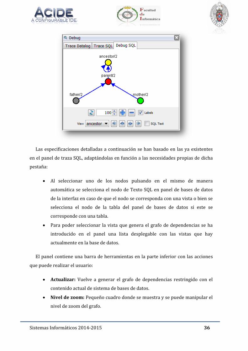
9.7.3. DEPURADOR SQL
En el panel depurador SQL, al igual que en el de traza, se muestra el grafo de
dependencias restringido a una de las vistas que se contienen actualmente en el
sistema de bases de datos. Además de la información de dependencias de la base de
datos y de las funcionalidades del panel PDG el panel tiene un mecanismo para
permitir que el usuario seleccione entre los distintos nodos del grafo cuál de ellos
quiere seleccionar para ampliar la información del mismo según la información de
traza SQL proporcionada por el sistema DES.
EL objetivo de la creación de esta pestaña es facilitar la depuración al usuario y con
tal fin ha sido desarrollado en este curso.
Sistemas Informáticos 2014-2015 36
Las especificaciones detalladas a continuación se han basado en las ya existentes
en el panel de traza SQL, adaptándolas en función a las necesidades propias de dicha
pestaña:
Al seleccionar uno de los nodos pulsando en el mismo de manera
automática se selecciona el nodo de Texto SQL en panel de bases de datos
de la interfaz en caso de que el nodo se corresponda con una vista o bien se
selecciona el nodo de la tabla del panel de bases de datos si este se
corresponde con una tabla.
Para poder seleccionar la vista que genera el grafo de dependencias se ha
introducido en el panel una lista desplegable con las vistas que hay
actualmente en la base de datos.
El panel contiene una barra de herramientas en la parte inferior con las acciones
que puede realizar el usuario:
Actualizar: Vuelve a generar el grafo de dependencias restringido con el
contenido actual de sistema de bases de datos.
Nivel de zoom: Pequeño cuadro donde se muestra y se puede manipular el
nivel de zoom del grafo.
Sistemas Informáticos 2014-2015 37
Etiquetas: Muestra u oculta las etiquetas con el nombre y la aridad de los
nodos.
Aumento de zoom: Aumenta el nivel de zoom del grafo.
Disminución de zoom: Disminuye el nivel de zoom del grafo.
Vista: Abre una lista desplegable con las vistas de la base de datos para que
el usuario seleccione aquella a partir de la cual quiere generar el grafo.
Primer nodo: Selecciona el primer nodo de la traza.
Nodo anterior: Selecciona el nodo anterior al nodo seleccionado
actualmente en el grafo de la traza.
Siguiente nodo: Selecciona el nodo anterior al nodo seleccionado
actualmente en el grafo de la traza.
Último nodo: Selecciona el último nodo de la traza.
Definición SQL: Activa o desactiva el destacado de los nodos de Texto SQL
y tabla correspondiente al nodo seleccionado.
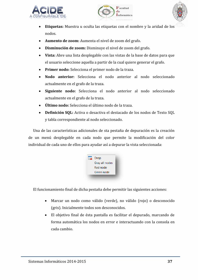
Una de las características adicionales de sta pestaña de depuración es la creación
de un menú desplegable en cada nodo que permite la modificación del color
individual de cada uno de ellos para ayudar así a depurar la vista seleccionada:
El funcionamiento final de dicha pestaña debe permitir las siguientes acciones:
Marcar un nodo como válido (verde), no válido (rojo) o desconocido
(gris). Inicialmente todos son desconocidos.
El objetivo final de ésta pantalla es facilitar el depurado, marcando de
forma automática los nodos en error e interactuando con la consola en
cada cambio.
Sistemas Informáticos 2014-2015 38
9.8. ACTUALIZACIÓN DEL MANUAL DE USUARIO
Al finalizar la release, se ha realizado una tarea extra, la actualización del manual
de usuario. Ha sido una tarea que se ha considerado como fundamental, primero, por
todo el trabajo que habían realizado los grupos de cursos anteriores al nuestro por
tener un manual completo y claro sobre la aplicación, y segundo, para ofrecer al
usuario una guía sencilla que le sirva para poder sacar todo el partido a ACIDE y
poder explotar todas las funcionalidades que ofrece.
Para la actualización del manual de usuario se ha partido del manual de usuario de
la versión anterior, y se han añadido las nuevas características implementadas en la
release. Se han seguido todos los convenios de estandarización descritos en la sección
correspondiente de la memoria con el fin de que la memoria sea homogénea y se ha
procurado que todas las ampliaciones del manual fueran entendibles para cualquier
persona que se disponga a usar ACIDE por primera vez.
Sistemas Informáticos 2014-2015 39
9.9. OBJETIVOS CUMPLIDOS
Los objetivos que se han cumplido satisfactoriamente en este proyecto son los que
se enumeran a continuación:
9.9.1. TAREAS DE CARÁCTER GENERAL
Localización al Francés.
Barra de estado copiable.
Cambio de ruta de la apertura de archivos.
Mantenimiento de la estandarización,
Compatibilidad Windows 7 – Windows XP.
9.9.2. PDG
Optimización de código en la búsqueda de nodo raíz
9.9.3. DEPURACIÓN
Dotar a ACIDE – A Configurable IDE de una nueva pestaña en el panel de
depuración que muestre de manera gráfica las trazas restringidas a
consultas SQL permitiendo la depuración de errores de las mismas.
Modificación del botón Refresh Datalog y SQL.
Desactivación por defecto casilla Reglas.
Modificación de la ventana Query.
Revisión de la traza de Datalog de forma que nos asegurásemos que el grafo
PDG se obtiene de "/tapi /pdg", y no accediendo directamente al predicado
dinámico PDG.
Modificación de la construcción del grafo SQL, cambiando /pdg por /rdg,
usando la versión publicada por Devel en Sourceforge.
Corrección del bug existente en el zoom.
9.9.4. BASE DE DATOS ASERTADA
Modificación de los botones Refresh y Clear
Sistemas Informáticos 2014-2015 40
9.9.5. CONSOLA
Adaptación de diferentes ejecutables.
Múltiples cambios de consola.
9.9.6. EDITOR DE TEXTOS
Apertura múltiple de nuevos archivos.
Atajo de ejecución (F9).
9.9.7. BASE DE DATOS
Mejora de la comunicación entre consola y panel Database.
Reapertura del panel.
Creación de botones Refresh y Reset.
9.9.8. AMPLIACIÓN DEL MANUAL DE USUARIO
Modificar todas las capturas de pantalla existentes en dicho manual.
Añadir la información sobre todas las nuevas funcionalidades y
modificaciones implementadas.
Sistemas Informáticos 2014-2015 41
9.10. OBJETIVOS NO CUMPLIDOS
En el momento que comencé el desarrollo del proyecto, el director Fernando
Sáenz Pérez me propuso una lista de objetivos para trabajar sobre la aplicación. Una
gran parte del trabajo durante el curso se ha centrado en la mejora de
funcionalidades, corrección de bugs y la creación de la nueva pestaña de depuración
SQL.
Dada a la priorización de tareas no ha sido posible completar todas las tareas que
se planificaron desde el principio, el listado de las tareas que no han podido ser
completadas son las siguientes:
Permitir enviar la señal de interrupción CTRL + C a la consola en el sistema
operativo Windows. La tarea original era enviar esa señal en cualquier
sistema operativo, y se ha conseguido hacer para sistemas operativos no
Windows, esto es debido a que Windows no permite al desarrollador la
manipulación de la señal. Se dedicó mucho esfuerzo y tiempo en investigar
posibles soluciones, se encontró una aplicación desarrollada por terceros
que permitía enviar la señal a un proceso elegido por el desarrollador, pero
tras integrar esa aplicación, las pruebas no dieron buenos resultados, por lo
que se decidió eliminar esta opción en Windows y dejarla operativa para el
resto de sistemas operativos.
Definir e implementar el análisis sintáctico para así poder aplicarlo en
ACIDE.
Definir y aplicar hilos en:
o Apertura de archivos en el editor. De esta forma el usuario tendría el
control de la aplicación mientras que se abren archivos.
o Apertura de proyectos en ACIDE. De forma similar al apartado
anterior, el usuario tendría el control de la aplicación mientras
termina la carga de un proyecto.
o Aplicación del formato léxico en el editor de archivos, como ocurre
en Microsoft Word cuando estamos aplicando la autocorrección. De
esta forma el usuario volvería a tener el control de la aplicación
Sistemas Informáticos 2014-2015 42
mientras que a los documentos se les aplica la configuración léxica
correspondiente.
Opción de respetar mayúsculas/minúsculas en los reemplazamientos. Esta
era una tarea que exigía una gran cantidad de esfuerzo para conseguir un
objetivo menos prioritario, por lo que se decidió dejar en beneficio de otras
consideradas más importantes.
Generar código SQL específico del Sistema Gestor de Bases de Datos para
las conexiones ODBC de forma similar a como se hace con DES. Dado el
escaso tiempo para culminar otras tareas con prioridad más alta, se decidió
relegar esta tarea para futuras versiones.
Añadir autocompletar a partir del diccionario léxico. Ésta fue una tarea que
surgió en las últimas semanas de desarrollo. En estas fechas comenzar esta
tarea significaba iniciar el desarrollo de algo desde cero, y dada la
proximidad de la entrega y la necesidad de subsanar otros errores, se dejó
esta tarea para futuras versiones.
En el panel de depuración SQL no se ha implementado la automatización en
la búsqueda de errores al usuario con el fin de encontrar resultados
erróneos o no esperados como se hace en DES [6] con los comandos
/debug_sql y /debug_datalog.
Sistemas Informáticos 2014-2015 43
9.11. CONCLUSIONES
Lo primero que hay que debemos tener en cuenta al hablar del desarrollo de la
aplicación ACIDE es que no es un proyecto que comienza a desarrollarse desde cero.
Cuando recuerdo los primeros días frente a la aplicación, recuerdo un proyecto de
gran tamaño (su código fuente llegaba a casi 300.000 líneas) y estable. Esto ha hecho
que la metodología de trabajo se haya tenido que adaptar a las circunstancias del
proyecto, por lo que la tarea no consistía solo en implementar nuevas
funcionalidades, sino que ha habido que aprender la estructura de un proyecto de un
tamaño considerable, el diseño de las diferentes partes de la aplicación, cómo se
integran esas partes, diseñar soluciones que se integren con el código ya desarrollado
y una vez implementadas esas soluciones, probar que la nueva funcionalidad tiene un
comportamiento correcto y probar también que los cambios realizados no impactan
sobre el funcionamiento del resto de la aplicación.
Otro punto importante, es el hecho que ACIDE es una aplicación publicada y en
funcionamiento, que está siendo utilizada por un gran número de personas de
distintos países del mundo y que todo lo hecho durante el curso ha sido publicado
para éstos usuarios. Esto ha implicado esfuerzo añadido para no romper la
experiencia que se le ha ofrecido al usuario durante toda la vida de ACIDE, que tanto
esfuerzo les costó conseguir a los compañeros que han participado en este proyecto
durante años anteriores.
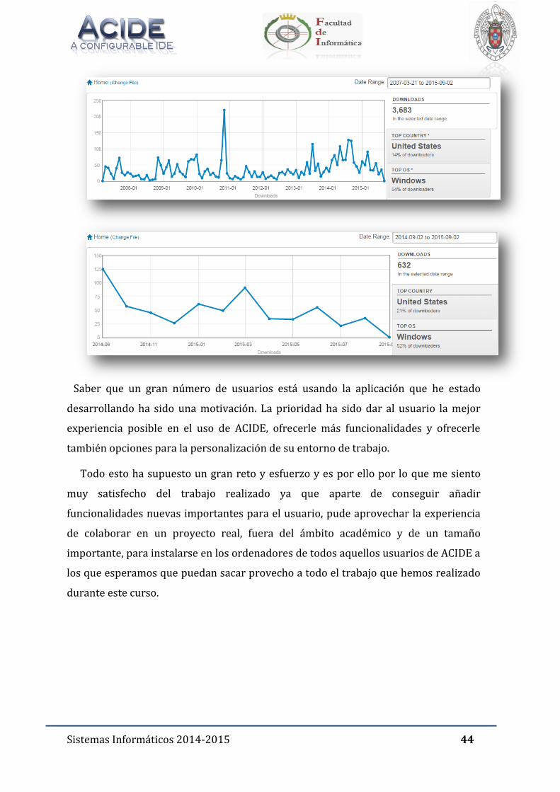
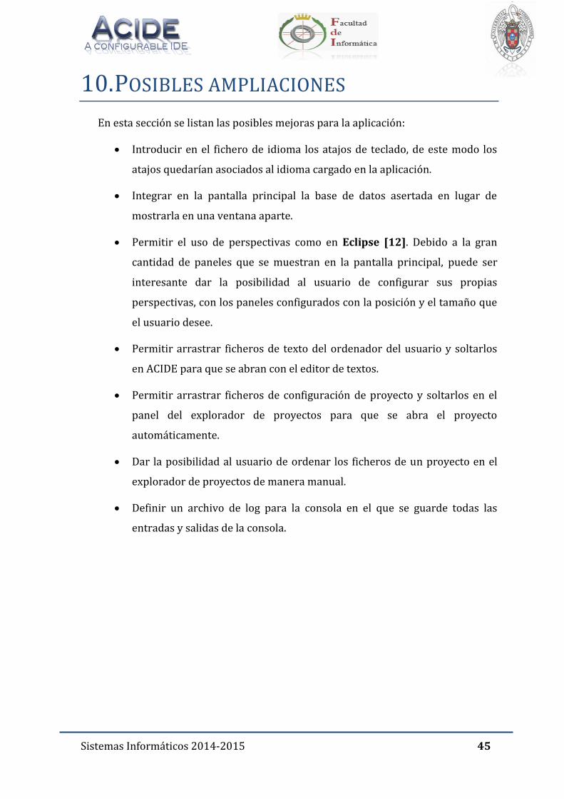
A continuación se muestran algunas estadísticas interesantes sobre las descargas
de ACIDE. Desde la primera publicación se ha llegado a contabilizar un número de
descargas superior a 3.600, de las cuales se han producido durante el actual curso
académico 632.
Sistemas Informáticos 2014-2015 44
Saber que un gran número de usuarios está usando la aplicación que he estado
desarrollando ha sido una motivación. La prioridad ha sido dar al usuario la mejor
experiencia posible en el uso de ACIDE, ofrecerle más funcionalidades y ofrecerle
también opciones para la personalización de su entorno de trabajo.
Todo esto ha supuesto un gran reto y esfuerzo y es por ello por lo que me siento
muy satisfecho del trabajo realizado ya que aparte de conseguir añadir
funcionalidades nuevas importantes para el usuario, pude aprovechar la experiencia
de colaborar en un proyecto real, fuera del ámbito académico y de un tamaño
importante, para instalarse en los ordenadores de todos aquellos usuarios de ACIDE a
los que esperamos que puedan sacar provecho a todo el trabajo que hemos realizado
durante este curso.
Sistemas Informáticos 2014-2015 45
10. POSIBLES AMPLIACIONES
En esta sección se listan las posibles mejoras para la aplicación:
Introducir en el fichero de idioma los atajos de teclado, de este modo los
atajos quedarían asociados al idioma cargado en la aplicación.
Integrar en la pantalla principal la base de datos asertada en lugar de
mostrarla en una ventana aparte.
Permitir el uso de perspectivas como en Eclipse [12]. Debido a la gran
cantidad de paneles que se muestran en la pantalla principal, puede ser
interesante dar la posibilidad al usuario de configurar sus propias
perspectivas, con los paneles configurados con la posición y el tamaño que
el usuario desee.
Permitir arrastrar ficheros de texto del ordenador del usuario y soltarlos
en ACIDE para que se abran con el editor de textos.
Permitir arrastrar ficheros de configuración de proyecto y soltarlos en el
panel del explorador de proyectos para que se abra el proyecto
automáticamente.
Dar la posibilidad al usuario de ordenar los ficheros de un proyecto en el
explorador de proyectos de manera manual.
Definir un archivo de log para la consola en el que se guarde todas las
entradas y salidas de la consola.
Sistemas Informáticos 2014-2015 46
11. LISTA DE PALABRAS CLAVES
DES.
Datalog.
Data view.
Design view.
Configurable.
Entorno de desarrollo integrado (IDE).
Base de datos.
Editor multi-archivo.
Búsqueda avanzada.
Consola.
Sistemas Informáticos 2014-2015 47
12. BIBLIOGRAFÍA
Para desarrollar el presente proyecto se han seguido las siguientes fuentes:
Explicación de la sintaxis de las restricciones pk, fk, ck, etc.
o Datalog Educational System V3.1 User’s Manual. Fernando Sáenz
Pérez. Universidad Complutense de Madrid. 2012.
Introducción a la aplicación en el manual:
o ACIDE: An Integrated Development Environment Configurable for
LATEX. Fernando Sáenz Pérez. The Practex Journal No3. 2007.
http://dw.tug.org/pracjourn/2007-3/saenz_perez-acide/saenz_perez-
acide.pdf
Sistemas Informáticos 2014-2015 48
13. REFERENCIAS
[1] D. Cardiel Freire, J. J. Ortiz Sánchez y D. Rupérez Cañas. ACIDE: A Configurable IDE. Universidad Complutense de Madrid. 2007.
[2] M. Martín Lázaro. ACIDE 0.2: a configurable integrated development environment. Universidad Complutense de Madrid. 2008.
[3] J. Salcedo Gómez. ACIDE: A Configurable IDE. DES GUI Front-end. Universidad Complutense de Madrid. 2011.
[4] P. Gutiérrez García-Pardo, E. Tejeiro Pérez de Ágreda, A. Vicente del Cura: A Configurable IDE. DES GUI Front-end. Universidad Complutense de Madrid. 2013
[5] J. J. Marqués Ortiz, F. Ordás Lorente y S. Gutiérrez Quintana: A Configurable IDE. DES GUI Front-end. Universidad Complutense de Madrid. 2014
[6] Página oficial de DES: http://www.fdi.ucm.es/profesor/fernan/des/index.html
[7] Página oficial de Crimson Editor: http://www.crimsoneditor.com
[8] Página oficial de JEdit: http://www.jedit.org
[9] Página oficial de JBuilder: http://www.borland.com/jbuilder
[10] Página oficial de JCreator: http://www.jcreator.com
[11] Página oficial de C++ Builder: http://www.borland.com/cppbuilder
[12] Página oficial de Eclipse: http://www.eclipse.org/
[13] Página oficial de Visual Studio Shell: http://msdn.microsoft.com/en-us/library/vstudio/bb685691.aspx
[14] Página oficial de WinEdt: http://www.winedt.com/
[15] Página oficial de NetBeans: http//netbeans.org
[16] Página oficial de MS Access: http://office.microsoft.com/es-es/access/
[17] Página oficial de Oracle: http://www.oracle.com
[18] Página oficial de Postgres: www.postgresql.org/
[19] Página oficial de TOra: http://torasql.com/
[20] Febbraro, O., Reale, K., Ricca, F.: ASPIDE: Integrated Development Environment for Answer Set Programming. In: Delgrande, J., Faber, W. (eds.) LPNMR 2011, LNAI 6645, pp. 317-330, 2011. Página oficial de ASPIDE: http://www.mat.unical.it/ricca/aspide/
[21] Página oficial de Dropbox: http://www.dropbox.com/
[22] Página oficial de Notepad++: http://www.notepad-plus-plus.org/

Sistemas Informáticos 2014-2015 49
[23] Página de referencia para la implementación del line wrapping: http://java-sl.com/wrap.html
[24] Página oficial de GitHub: https://github.com/
Sistemas Informáticos 2014-2015 50
14. INFORMACIÓN DE CONTACTO
Este proyecto es código libre. Por tanto, todo el código fuente y ejecutables están
disponibles en las siguientes direcciones de internet:
Ejecutable: http://www.fdi.ucm.es/profesor/fernan/ACIDE/
Código fuente: http://sourceforge.net/projects/acide/files/acide/
Si quisiera ponerse en contacto con alguno de los desarrolladores del proyecto
puede hacerlo a través de las siguientes direcciones de correo electrónico:
Sergio Domínguez Fuentes: [email protected]

Sistemas Informáticos 2014-2015 51
APÉNDICE: MANUAL DE USUARIO

USER’S MANUAL
VERSION 0.17

User’s Manual 2
SUMMARIZED INDEX
Summarized index ............................................................................................................................ 2
Index of contents ............................................................................................................................... 5
Index of Figures ...............................................................................................................................19
1. System requirements ..........................................................................................................25
1.1. User................................................................................................................................... 25
1.2. Developer ....................................................................................................................... 26
1.3. Executing ACIDE ........................................................................................................... 26
2. Introducing ACIDE ...............................................................................................................27
2.1. Technology..................................................................................................................... 27
2.2. The Main GUI ................................................................................................................. 27
2.3. Projects ........................................................................................................................... 29
2.4. Configuration ................................................................................................................ 29
3. Menu bar ..................................................................................................................................30
3.1. File menu ........................................................................................................................ 30
3.2. Edit menu ....................................................................................................................... 32
3.3. Project menu ................................................................................................................. 39
3.4. View menu ..................................................................................................................... 46
3.5. Configuration menu .................................................................................................... 47
3.6. Help menu ...................................................................................................................... 79
3.7. Inserted submenus ..................................................................................................... 80
3.8. Inserted menu items .................................................................................................. 81

User’s Manual 3
4. Project browser panel ........................................................................................................ 82
5. File editor panel ................................................................................................................... 83
6. Tool bar .................................................................................................................................... 85
7. Console panel ........................................................................................................................ 86
8. Database panel ...................................................................................................................... 88
8.1. Databases node ............................................................................................................ 88
8.2. Database node .............................................................................................................. 90
8.3. Tables node ................................................................................................................... 92
8.4. Table node ..................................................................................................................... 93
8.5. Children of table nodes ........................................................................................... 122
8.6. Views node .................................................................................................................. 123
8.7. View node .................................................................................................................... 125
8.8. Columns nodes ........................................................................................................... 126
8.9. SQL text , RA text and Datalog text nodes ......................................................... 126
9. PDG panel ..............................................................................................................................129
10. Debug Panel.....................................................................................................................130
10.1. Trace datalog panel .................................................................................................. 130
10.2. Trace SQL panel ......................................................................................................... 132
10.3. Debug SQL panel ....................................................................................................... 134
11. Asserted Database Panel ............................................................................................136
12. Status bar .........................................................................................................................137
13. Accessibility shortcuts ................................................................................................138
13.1. Accessibility shortcuts in English ...................................................................... 138
User’s Manual 4
13.2. Accessibility shortcuts in Spanish ..................................................................... 141
13.3. Accessibility shortcuts in French ....................................................................... 144
14. ACIDE Variables ............................................................................................................ 147
15. ACIDE default Commands ......................................................................................... 148
16. Configuration of ACIDE by configuration documents .................................... 154
16.1. Managers in XML files ............................................................................................. 154
16.2. Properties configuration ....................................................................................... 154
16.3. Workbench configuration ..................................................................................... 156
16.4. Project configuration .............................................................................................. 161
16.5. Configuration of lexicons ....................................................................................... 163
16.6. Commands history ................................................................................................... 165
17. Regular Expressions .................................................................................................... 166
17.1. Construction of regular expressions ................................................................. 166
17.2. Description of regular expressions .................................................................... 167
User’s Manual 5
INDEX OF CONTENTS
Index of contents ............................................................................................................................... 5
Index of Figures ............................................................................................................................... 19
1. System requirements ......................................................................................................... 25
1.1. User .................................................................................................................................. 25
1.2. Developer ...................................................................................................................... 26
1.3. Executing ACIDE .......................................................................................................... 26
2. Introducing ACIDE ............................................................................................................... 27
2.1. Technology .................................................................................................................... 27
2.2. The Main GUI ................................................................................................................ 27
2.3. Projects ........................................................................................................................... 29
2.4. Configuration ............................................................................................................... 29
3. Menu bar ................................................................................................................................. 30
3.1. File menu ....................................................................................................................... 30
3.1.1. New ............................................................................................................................................ 30
3.1.2. Open .......................................................................................................................................... 30
3.1.3. Open recent files ................................................................................................................... 30
3.1.4. Open all files ........................................................................................................................... 31
3.1.5. Close file ................................................................................................................................... 31
3.1.6. Close all files ........................................................................................................................... 31
3.1.7. Save file .................................................................................................................................... 31
3.1.8. Save file as ............................................................................................................................... 31

User’s Manual 6
3.1.9. Save all files ............................................................................................................................ 31
3.1.10. Print file .............................................................................................................................. 31
3.1.11. Exit ........................................................................................................................................ 31
3.2. Edit menu ....................................................................................................................... 32
3.2.1. Undo........................................................................................................................................... 33
3.2.2. Redo ........................................................................................................................................... 33
3.2.3. Copy ........................................................................................................................................... 33
3.2.4. Paste .......................................................................................................................................... 33
3.2.5. Cut ............................................................................................................................................... 33
3.2.6. Toggle comment ................................................................................................................... 33
3.2.7. Make comment ...................................................................................................................... 33
3.2.8. Release comment ................................................................................................................. 33
3.2.9. Change case ............................................................................................................................ 34
3.2.9.1 Upper case.......................................................................................................................... 34
3.2.9.2 Lower case ......................................................................................................................... 34
3.2.9.3 Capitalize ............................................................................................................................ 34
3.2.9.4 Invert case .......................................................................................................................... 34
3.2.10. Select all .............................................................................................................................. 34
3.2.11. Go to line ............................................................................................................................. 34
3.2.12. Search .................................................................................................................................. 35
3.2.13. Replace ................................................................................................................................ 36
3.3. Project menu ................................................................................................................. 39
User’s Manual 7
3.3.1. New project ............................................................................................................................ 40
3.3.2. Open project ........................................................................................................................... 41
3.3.3. Open recent projects .......................................................................................................... 41
3.3.4. Close project ........................................................................................................................... 41
3.3.5. Save project ............................................................................................................................ 41
3.3.6. Save project as ....................................................................................................................... 41
3.3.7. New project file ..................................................................................................................... 41
3.3.8. Add all opened files ............................................................................................................. 41
3.3.9. Add file ..................................................................................................................................... 41
3.3.10. Remove file ........................................................................................................................ 41
3.3.11. Delete file ........................................................................................................................... 41
3.3.12. Add folder .......................................................................................................................... 42
3.3.13. Remove folder .................................................................................................................. 42
3.3.14. Compile project ............................................................................................................... 43
3.3.14.1. Compilation based on “Extension” .......................................................................... 43
3.3.14.2. Compilation based on “Marked files for compilation”..................................... 43
3.3.15. Execute project ................................................................................................................ 44
3.3.16. Set compilable file .......................................................................................................... 45
3.3.17. Unset compilable file ..................................................................................................... 45
3.3.18. Set main file ....................................................................................................................... 46
3.3.19. Unset main file ................................................................................................................. 46
3.4. View menu ..................................................................................................................... 46
User’s Manual 8
3.4.1. Show log ................................................................................................................................... 46
3.4.2. Project browser .................................................................................................................... 46
3.4.3. Console ..................................................................................................................................... 46
3.4.4. Database ................................................................................................................................... 47
3.4.5. PDG ............................................................................................................................................. 47
3.4.6. Debug ........................................................................................................................................ 47
3.4.7. Asserted Database ............................................................................................................... 47
3.5. Configuration menu .................................................................................................... 47
3.5.1. Lexicon configuration ......................................................................................................... 48
3.5.1.1. New lexicon ....................................................................................................................... 48
3.5.1.2. Document lexicon ........................................................................................................... 48
3.5.1.3. Modify lexicon .................................................................................................................. 48
3.5.1.3.1. Reserved words configuration ................................................................................. 49
3.5.1.3.2. Delimiters configuration ............................................................................................. 50
3.5.1.3.3. Remarks configuration ................................................................................................ 51
3.5.1.4. Default lexicons ............................................................................................................... 52
3.5.2. Grammar configuration ..................................................................................................... 53
3.5.2.1. New grammar ................................................................................................................... 53
3.5.2.2. Load grammar .................................................................................................................. 55
3.5.2.3. Modify grammar .............................................................................................................. 55
3.5.2.4. Save grammar ................................................................................................................... 56
3.5.2.5. Save grammar as ............................................................................................................. 56
User’s Manual 9
3.5.2.6. Configure paths ............................................................................................................... 56
3.5.3. Compiler .................................................................................................................................. 57
3.5.4. File editor configuration ................................................................................................... 58
3.5.4.1. Preferences ........................................................................................................................ 58
3.5.4.2. File editor display options configuration ............................................................. 59
3.5.4.3. Automatic indent ............................................................................................................ 60
3.5.4.4. Line wrapping .................................................................................................................. 60
3.5.4.5. Maximum line number to send to console ........................................................... 60
3.5.4.6. Send to console confirmation .................................................................................... 60
3.5.5. Console configuration ........................................................................................................ 61
3.5.5.1. Configuration .................................................................................................................... 61
3.5.5.2. Execute external command ........................................................................................ 62
3.5.5.3. Console display configuration ................................................................................... 62
3.5.5.4. Line wrapping .................................................................................................................. 63
3.5.5.5. Save content into file ..................................................................................................... 63
3.5.5.6. Document lexicon ........................................................................................................... 64
3.5.5.7. Find ....................................................................................................................................... 64
3.5.5.8. Close console .................................................................................................................... 65
3.5.5.9. Reset console .................................................................................................................... 65
3.5.5.10. Clear console buffer ....................................................................................................... 65
3.5.6. Database panel configuration ......................................................................................... 65
3.5.6.1. DES panel ........................................................................................................................... 65

User’s Manual 10
3.5.6.2. ODBC panel ........................................................................................................................ 66
3.5.6.3. Show details ...................................................................................................................... 66
3.5.6.3.1. Name ................................................................................................................................... 66
3.5.6.3.2. Name fields ....................................................................................................................... 66
3.5.6.3.3. Name fields types ........................................................................................................... 66
3.5.7. Graph panel configuration ................................................................................................ 66
3.5.7.1. Node color .......................................................................................................................... 67
3.5.7.2. Show Labels ....................................................................................................................... 67
3.5.7.3. Node shape ........................................................................................................................ 67
3.5.7.4. Arrow color ....................................................................................................................... 67
3.5.7.5. Arrow shape ...................................................................................................................... 68
3.5.8. Debug panel configuration ............................................................................................... 68
3.5.8.1. Node color .......................................................................................................................... 68
3.5.8.2. Selected node color ........................................................................................................ 68
3.5.8.3. Show Labels ....................................................................................................................... 68
3.5.8.4. Node shape ........................................................................................................................ 69
3.5.8.5. Arrow color ....................................................................................................................... 69
3.5.8.6. Arrow shape ...................................................................................................................... 69
3.5.9. Language configuration ..................................................................................................... 69
3.5.10. Menu configuration ........................................................................................................ 70
3.5.10.1. New ....................................................................................................................................... 70
3.5.10.1.1. Buttons panel ................................................................................................................ 72

User’s Manual 11
3.5.10.1.2. Popup menu .................................................................................................................. 73
3.5.10.1.3. Key navegation ............................................................................................................. 74
3.5.10.2. Load ...................................................................................................................................... 74
3.5.10.3. Modify .................................................................................................................................. 74
3.5.10.4. Save ....................................................................................................................................... 75
3.5.10.5. Save as ................................................................................................................................. 75
3.5.11. Toolbar configuration ................................................................................................... 75
3.5.11.1. New ....................................................................................................................................... 76
3.5.11.2. Load ...................................................................................................................................... 77
3.5.11.3. Modify .................................................................................................................................. 78
3.5.11.4. Save ....................................................................................................................................... 78
3.5.11.5. Save as ................................................................................................................................. 78
3.6. Help menu ..................................................................................................................... 79
3.6.1. Show help ................................................................................................................................ 79
3.6.2. About us ................................................................................................................................... 79
3.7. Inserted submenus ..................................................................................................... 80
3.8. Inserted menu items .................................................................................................. 81
4. Project browser panel ........................................................................................................ 82
5. File editor panel ................................................................................................................... 83
6. Tool bar .................................................................................................................................... 85
7. Console panel ........................................................................................................................ 86
8. Database panel ...................................................................................................................... 88
8.1. Databases node ............................................................................................................ 88
User’s Manual 12
8.1.1. Open ........................................................................................................................................... 89
8.1.2. Refresh ...................................................................................................................................... 89
8.1.3. Close ........................................................................................................................................... 89
8.2. Database node .............................................................................................................. 90
8.2.1. Set as default .......................................................................................................................... 90
8.2.2. Close ........................................................................................................................................... 90
8.2.3. Refresh ...................................................................................................................................... 90
8.2.4. Execute query ........................................................................................................................ 91
8.3. Tables node ................................................................................................................... 92
8.3.1. Create table with Datalog.................................................................................................. 92
8.3.2. Create table with Design view ........................................................................................ 92
8.3.3. Create table with SQL ......................................................................................................... 93
8.3.4. Paste .......................................................................................................................................... 93
8.3.5. Show details ........................................................................................................................... 93
8.4. Table node ..................................................................................................................... 93
8.4.1. Drop ........................................................................................................................................... 94
8.4.2. Rename ..................................................................................................................................... 94
8.4.3. Copy ........................................................................................................................................... 94
8.4.4. Design view ............................................................................................................................. 95
8.4.5. Data view ................................................................................................................................. 95
8.4.5.1. Actions permitted on the grid .................................................................................... 96
8.4.5.2. Menu bar ............................................................................................................................. 97

User’s Manual 13
8.4.5.2.1. File menu ........................................................................................................................... 97
8.4.5.2.1.1. Export .............................................................................................................................. 97
8.4.5.2.1.2. Import ............................................................................................................................. 98
8.4.5.2.1.3. Execute query .............................................................................................................. 98
8.4.5.2.1.4. Print ................................................................................................................................. 98
8.4.5.2.1.5. Close ................................................................................................................................. 98
8.4.5.2.2. Edit menu .......................................................................................................................... 99
8.4.5.2.2.1. Undo................................................................................................................................. 99
8.4.5.2.2.2. Redo ................................................................................................................................. 99
8.4.5.2.2.3. Copy ................................................................................................................................. 99
8.4.5.2.2.4. Paste ................................................................................................................................ 99
8.4.5.2.2.5. Cut ..................................................................................................................................... 99
8.4.5.2.2.6. Find ............................................................................................................................... 100
8.4.5.2.2.7. Replace ........................................................................................................................ 100
8.4.5.2.3. Records menu ............................................................................................................... 101
8.4.5.2.3.1. New ............................................................................................................................... 101
8.4.5.2.3.2. Delete ........................................................................................................................... 101
8.4.5.2.3.3. Refresh ......................................................................................................................... 101
8.4.5.2.3.4. Go to .............................................................................................................................. 101
8.4.5.2.3.5. Select record .............................................................................................................. 102
8.4.5.2.3.6. Select all ...................................................................................................................... 102
8.4.5.2.4. View menu ..................................................................................................................... 102

User’s Manual 14
8.4.5.2.4.1. Sort by .......................................................................................................................... 103
8.4.5.2.4.2. Sort by column .......................................................................................................... 103
8.4.5.2.4.3. Filter by content ....................................................................................................... 104
8.4.5.2.4.4. Filter excluding content ........................................................................................ 104
8.4.5.2.4.5. Discard filter .............................................................................................................. 104
8.4.5.2.4.6. Hide/show columns ............................................................................................... 104
8.4.5.2.5. Help menu ...................................................................................................................... 105
8.4.5.2.5.1. Show help ................................................................................................................... 105
8.4.5.2.5.2. About us ...................................................................................................................... 106
8.4.6. Constraints ........................................................................................................................... 107
8.4.6.1. Primary Key Panel (PK)............................................................................................. 107
8.4.6.1.1. Defining a primary key ............................................................................................. 108
8.4.6.1.2. Modifying a primary key .......................................................................................... 108
8.4.6.1.3. Deleting a primary key ............................................................................................. 109
8.4.6.2. Candidate key panel (CK) ......................................................................................... 109
8.4.6.2.1. Defining a candidate key .......................................................................................... 109
8.4.6.2.2. Modifying a candidate key....................................................................................... 110
8.4.6.2.3. Deleting a candidate key .......................................................................................... 110
8.4.6.2.4. Foreign key panel (FK) ............................................................................................. 111
8.4.6.2.5. Defining a foreign key ............................................................................................... 114
8.4.6.2.6. Modifying a foreign key ............................................................................................ 115
8.4.6.2.7. Deleting a foreign key................................................................................................ 115

User’s Manual 15
8.4.6.3. Not null panel (NN) ..................................................................................................... 115
8.4.6.3.1. Defining a not null constraint ................................................................................ 116
8.4.6.3.2. Modifying a not null constraint ............................................................................. 116
8.4.6.3.3. Deleting a not null constraint ................................................................................ 116
8.4.6.4. Functional dependency panel (FD) ...................................................................... 117
8.4.6.4.1. Defining a functional dependency constraint ................................................. 117
8.4.6.4.2. Modifying a functional dependency constraint .............................................. 118
8.4.6.4.3. Deleting a functional dependency constraint ................................................. 118
8.4.6.5. Integrity constraints panel (IC) ............................................................................. 119
8.4.6.5.1. Defining a user defined constraint ...................................................................... 120
8.4.6.5.2. Modifying a user defined constraint ................................................................... 120
8.4.6.5.3. Deleting a user defined constraint ....................................................................... 121
8.5. Children of table nodes ........................................................................................... 122
8.5.1. Node Columns .................................................................................................................... 122
8.5.2. Node Constraints ............................................................................................................... 123
8.5.2.1. Drop ................................................................................................................................... 123
8.5.2.2. Modify ............................................................................................................................... 123
8.6. Views node .................................................................................................................. 123
8.6.1. Create ..................................................................................................................................... 124
8.6.2. Paste ....................................................................................................................................... 124
8.6.3. Show details ........................................................................................................................ 124
8.7. View node .................................................................................................................... 125

User’s Manual 16
8.7.1. Drop ........................................................................................................................................ 125
8.7.2. Rename .................................................................................................................................. 125
8.7.3. Copy ........................................................................................................................................ 125
8.7.4. Paste ....................................................................................................................................... 126
8.7.5. Design view .......................................................................................................................... 126
8.7.6. Data view .............................................................................................................................. 126
8.8. Columns nodes .......................................................................................................... 126
8.9. SQL text , RA text and Datalog text nodes ........................................................ 126
9. PDG panel ............................................................................................................................. 129
10. Debug Panel .................................................................................................................... 130
10.1. Trace datalog panel ................................................................................................. 130
10.2. Trace SQL panel ........................................................................................................ 132
10.3. Debug SQL panel ....................................................................................................... 134
11. Asserted Database Panel............................................................................................ 136
12. Status bar ......................................................................................................................... 137
13. Accessibility shortcuts ................................................................................................ 138
13.1. Accessibility shortcuts in English ...................................................................... 138
13.2. Accessibility shortcuts in Spanish ..................................................................... 141
13.3. Accessibility shortcuts in French ....................................................................... 144
14. ACIDE Variables ............................................................................................................ 147
15. ACIDE default Commands ......................................................................................... 148
16. Configuration of ACIDE by configuration documents .................................... 154
16.1. Managers in XML files ............................................................................................. 154

User’s Manual 17
16.2. Properties configuration ........................................................................................ 154
16.3. Workbench configuration ..................................................................................... 156
16.3.1. Menu configuration ..................................................................................................... 157
16.3.2. Toolbar configuration ................................................................................................ 158
16.3.3. File editor configuration ........................................................................................... 160
16.3.4. Console panel configuration.................................................................................... 161
16.3.5. lexiconAssigner configuration ................................................................................ 161
16.4. Project configuration .............................................................................................. 161
16.5. Configuration of lexicons ....................................................................................... 163
16.5.1. TokenType Manager ................................................................................................... 164
16.5.2. validExtension Manager ........................................................................................... 164
16.5.3. delimiters Manager ..................................................................................................... 165
16.6. Commands history ................................................................................................... 165
17. Regular Expressions ....................................................................................................166
17.1. Construction of regular expressions ................................................................. 166
17.2. Description of regular expressions .................................................................... 167
17.2.1. The DOT “.” ..................................................................................................................... 167
17.2.2. The BACKSLASH “” ...................................................................................................... 167
17.2.3. The BRACKETS “[]” ..................................................................................................... 168
17.2.4. The BAR “|” ..................................................................................................................... 168
17.2.5. The DOLLAR SIGN “$” ................................................................................................ 169
17.2.6. The CARET “^” .............................................................................................................. 169

User’s Manual 18
17.2.7. Parentheses “()” ............................................................................................................ 169
17.2.8. The QUESTION mark “?” ........................................................................................... 170
17.2.9. The BRACES “{}” ........................................................................................................... 170
17.2.10. The ASTERISK “*” ......................................................................................................... 170
17.2.11. The PLUS sign “+” ......................................................................................................... 170

User’s Manual 19
INDEX OF FIGURES
Figure 1: ACIDE Main GUI .............................................................................................................. 28
Figure 2: File Menu ........................................................................................................................... 30
Figure 3: Edit Menu .......................................................................................................................... 32
Figure 4: Change Case Menu ......................................................................................................... 34
Figure 5: Go to line window .......................................................................................................... 35
Figure 6: Search window ................................................................................................................ 35
Figure 7: Replace window ............................................................................................................. 37
Figure 8: Number of replacements ............................................................................................. 39
Figure 9: Project menu .................................................................................................................... 39
Figure 10: Project configuration ................................................................................................. 40
Figure 11: Add folder ....................................................................................................................... 42
Figure 12: Compilation by extension ......................................................................................... 43
Figure 13: Marking files .................................................................................................................. 44
Figure 14: Compilation by marked files ................................................................................... 44
Figure 15: Execution menu............................................................................................................ 45
Figure 16: Execution process ....................................................................................................... 45
Figure 17: View menu...................................................................................................................... 46
Figure 18: Configuration menu .................................................................................................... 47
Figure 19: Lexicon menu ................................................................................................................ 48
Figure 20: New lexicon.................................................................................................................... 48
Figure 21: Reserved words ........................................................................................................... 49
Figure 22: Delimiters configuration ........................................................................................... 50
Figure 23: Remarks configuration .............................................................................................. 51
Figure 24: Default lexicons ............................................................................................................ 52
User’s Manual 20
Figure 25: Grammar menu .............................................................................................................53
Figure 26: New grammar ................................................................................................................54
Figure 27: Grammar generation process ..................................................................................55
Figure 28: Modify grammar ...........................................................................................................56
Figure 29: Set paths ..........................................................................................................................57
Figure 30: Compiler configuration ..............................................................................................57
Figure 31: File editor configuration ............................................................................................58
Figure 32: Preferences window ...................................................................................................59
Figure 33: File editor display options ........................................................................................59
Figure 34: Maximum line number ...............................................................................................60
Figure 35: Console menu ................................................................................................................61
Figure 36: Console configuration ................................................................................................61
Figure 37: Execute external command ......................................................................................62
Figure 38: Console display configuration .................................................................................63
Figure 39: Console search window .............................................................................................64
Figure 40: Database panel menu .................................................................................................65
Figure 41: Show Details Menu ......................................................................................................66
Figure 42 : Graph Panel Configuration menu .........................................................................66
Figure 43: Node shape menu .........................................................................................................67
Figure 44: Arrow color menu ........................................................................................................67
Figure 45: Arrow shape menu ......................................................................................................68
Figure 46 : Debug Panel Configuration menu .........................................................................68
Figure 47: Node shape menu .........................................................................................................69
Figure 48: Arrow color menu ........................................................................................................69
Figure 49: Arrow shape menu ......................................................................................................69
Figure 50: Language configuration menu ................................................................................70

User’s Manual 21
Figure 51: Menu configuration menu ........................................................................................ 70
Figure 52: New menu ...................................................................................................................... 70
Figure 53: Object menu popup menu ........................................................................................ 73
Figure 54: Modify menu.................................................................................................................. 75
Figure 55: Tool Bar configuration menu .................................................................................. 75
Figure 56: New tool bar .................................................................................................................. 76
Figure 57: Modify tool bar ............................................................................................................. 78
Figure 58: Help menu ...................................................................................................................... 79
Figure 59: About us window ......................................................................................................... 79
Figure 60: Example of inserted submenu ................................................................................ 80
Figure 61: Project browser panel ............................................................................................... 82
Figure 62: Project browser popup menu ................................................................................. 82
Figure 63: File editor panel ........................................................................................................... 83
Figure 64: File editor popup menu ............................................................................................. 84
Figure 65: Tool bar ........................................................................................................................... 85
Figure 66: Console panel ................................................................................................................ 86
Figure 67: Console panel popup menu ..................................................................................... 86
Figure 68: Database panel ............................................................................................................. 88
Figure 69: Databases node ............................................................................................................ 88
Figure 70: Databases node popup menu .................................................................................. 89
Figure 71: Open database .............................................................................................................. 89
Figure 72: Database node .............................................................................................................. 90
Figure 73: Database node popup menu .................................................................................... 90
Figure 74: Execute query ............................................................................................................... 91
Figure 75: Expanding database node ........................................................................................ 91
Figure 76: Tables node popup menu ......................................................................................... 92

User’s Manual 22
Figure 77: New table.........................................................................................................................92
Figure 78: Show Details Menu Tables Node ............................................................................93
Figure 79: Table node ......................................................................................................................94
Figure 80: Table node popup menu ............................................................................................94
Figure 81: Design view ....................................................................................................................95
Figure 82: Data view .........................................................................................................................95
Figure 83: Column header popup ................................................................................................96
Figure 84: Data view file menu .....................................................................................................97
Figure 85: Execute query ................................................................................................................98
Figure 86: Data view edit menu ...................................................................................................99
Figure 87: Data view search window ...................................................................................... 100
Figure 88: Data view replace window .................................................................................... 100
Figure 89: Data view number of replacements ................................................................... 100
Figure 90: Data view records menu......................................................................................... 101
Figure 91: Data view go to menu .............................................................................................. 101
Figure 92: View menu in Data View ........................................................................................ 102
Figure 93: Data view sort by window ..................................................................................... 103
Figure 94: Data view hide/show columns ............................................................................ 104
Figure 95: Data view help menu ............................................................................................... 105
Figure 96: Data view about us window .................................................................................. 106
Figure 97: Constraints Window ................................................................................................ 107
Figure 98: Primary Key Panel .................................................................................................... 108
Figure 99: Candidate Key Panel ................................................................................................ 109
Figure 100: Foreign Key Panel................................................................................................... 111
Picture 101: Table Chooser Window ...................................................................................... 112
Figure 102: Referenced relation window .............................................................................. 113

User’s Manual 23
Figure 103: Referenced relations window ............................................................................113
Figure 104: Not Null Panel ..........................................................................................................116
Figure 105: Functional Dependency panel ...........................................................................117
Figure 106: Integrity Constraints Panel .................................................................................119
Figure 107: Children of table nodes .........................................................................................122
Figure 108: Column node popup ...............................................................................................122
Figure 109: Node Constraints Popup Menu ..........................................................................123
Figure 110: Views Node Popup Menu .....................................................................................123
Figure 111: Create view window ..............................................................................................124
Figure 112: Show Details Menu Views Node ........................................................................124
Figure 113: View node ..................................................................................................................125
Figure 114: View node popup menu ........................................................................................125
Figure 115: Columns nodes .........................................................................................................126
Figure 116: SQL and Datalog text nodes ................................................................................127
Figure 117: SQL text .......................................................................................................................127
Figure 118: Datalog text ...............................................................................................................128
Figure 119: PDG Panel ...................................................................................................................129
Figure 120: Debug Panel ..............................................................................................................130
Figure 121: Selected Node ...........................................................................................................131
Figure 122: Highlighted text .......................................................................................................131
Figure 123: Query window ..........................................................................................................131
Figure 124: Trace SQL panel .......................................................................................................133
Figure 125: Debug SQL panel .....................................................................................................134
Figure 126: Debug node popup menu .....................................................................................135
Figure 127: Asserted Database Panel ................................................................................136
Figure 128: Status bar ...................................................................................................................137

User’s Manual 24
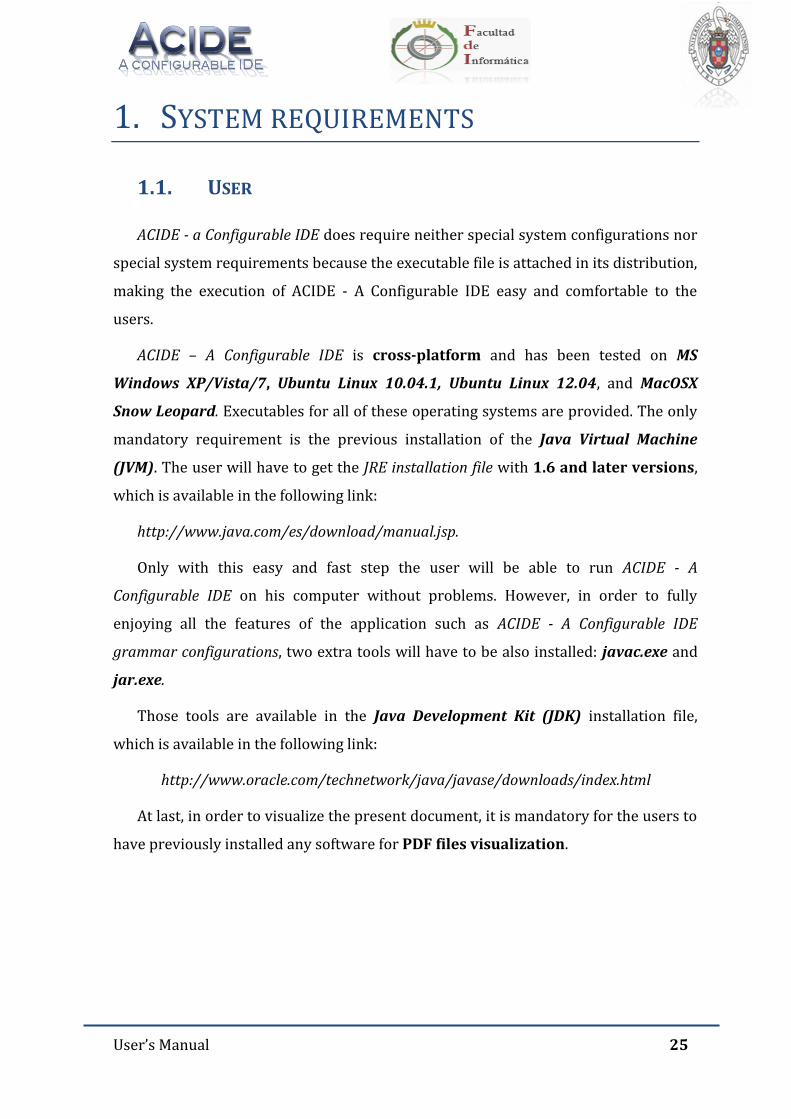
User’s Manual 25
1. SYSTEM REQUIREMENTS
1.1. USER
ACIDE - a Configurable IDE does require neither special system configurations nor
special system requirements because the executable file is attached in its distribution,
making the execution of ACIDE - A Configurable IDE easy and comfortable to the
users.
ACIDE – A Configurable IDE is cross-platform and has been tested on MS
Windows XP/Vista/7, Ubuntu Linux 10.04.1, Ubuntu Linux 12.04, and MacOSX
Snow Leopard. Executables for all of these operating systems are provided. The only
mandatory requirement is the previous installation of the Java Virtual Machine
(JVM). The user will have to get the JRE installation file with 1.6 and later versions,
which is available in the following link:
http://www.java.com/es/download/manual.jsp.
Only with this easy and fast step the user will be able to run ACIDE - A
Configurable IDE on his computer without problems. However, in order to fully
enjoying all the features of the application such as ACIDE - A Configurable IDE
grammar configurations, two extra tools will have to be also installed: javac.exe and
jar.exe.
Those tools are available in the Java Development Kit (JDK) installation file,
which is available in the following link:
http://www.oracle.com/technetwork/java/javase/downloads/index.html
At last, in order to visualize the present document, it is mandatory for the users to
have previously installed any software for PDF files visualization.
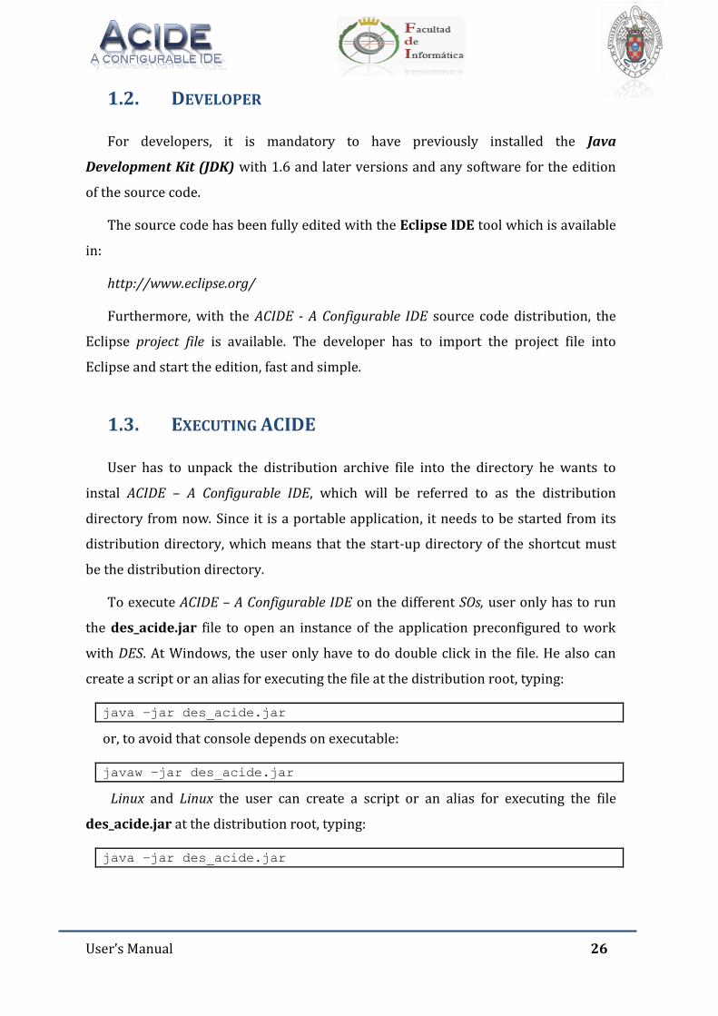
User’s Manual 26
1.2. DEVELOPER
For developers, it is mandatory to have previously installed the Java
Development Kit (JDK) with 1.6 and later versions and any software for the edition
of the source code.
The source code has been fully edited with the Eclipse IDE tool which is available
in:
http://www.eclipse.org/
Furthermore, with the ACIDE - A Configurable IDE source code distribution, the
Eclipse project file is available. The developer has to import the project file into
Eclipse and start the edition, fast and simple.
1.3. EXECUTING ACIDE
User has to unpack the distribution archive file into the directory he wants to
instal ACIDE – A Configurable IDE, which will be referred to as the distribution
directory from now. Since it is a portable application, it needs to be started from its
distribution directory, which means that the start-up directory of the shortcut must
be the distribution directory.
To execute ACIDE – A Configurable IDE on the different SOs, user only has to run
the des_acide.jar file to open an instance of the application preconfigured to work
with DES. At Windows, the user only have to do double click in the file. He also can
create a script or an alias for executing the file at the distribution root, typing:
java –jar des_acide.jar
or, to avoid that console depends on executable:
javaw –jar des_acide.jar
Linux and Linux the user can create a script or an alias for executing the file
des_acide.jar at the distribution root, typing:
java –jar des_acide.jar

User’s Manual 27
2. INTRODUCING ACIDE
ACIDE – A Configurable IDE is a cross-platform, open-source Integrated
Development Environment (IDE). It has been developed by different teams of
students coursing Computing Systems and directed by Fernando Sáenz Pérez. Next,
ACIDE – A Configurable IDE features will be further explained:
2.1. TECHNOLOGY
The implementation of the application has been completely done using Java under
Eclipse. Version control was kindly provided by Tortoise SVN.
2.2. THE MAIN GUI
Figure 1 shows the main GUI of ACIDE. It consists of six main panels. The top panel
on the left shows the organistation of the current project, the top panel in the middle
are the opened files which may belong to the project (files may be opened without
assigning them to the project), the top panel on the right side is the graph panel,
which shows the PD. Below, the left panel shows the databases system connected
with ACIDE, which allows user interaction. Beside, the console panel is shown. The
case shown is the DES console and on the right side the debug panel is shown, which
allows the graphical debugging. The databases, console, project, graph and debug
panels can be hidden. Also, these panels can be switched by a drag and drop action.
For this purpose, the menu bars (or the tabbed pane in the File Editor) in the panels
can be selected using the left mouse button, after that, the panels can be dragged and
released one in another. Moreover, there is no need to work with projects if this
flexibility is not needed; a regular user may use the system as is. The status of the GUI
is remembered for the next time the tool is executed. If the tool opens a project, its
status when it was last saved is restored.
The menu bar includes some common entries:
File: For file related operations.
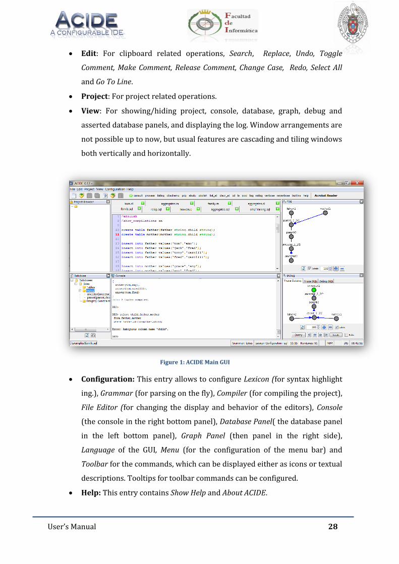
User’s Manual 28
Edit: For clipboard related operations, Search, Replace, Undo, Toggle
Comment, Make Comment, Release Comment, Change Case, Redo, Select All
and Go To Line.
Project: For project related operations.
View: For showing/hiding project, console, database, graph, debug and
asserted database panels, and displaying the log. Window arrangements are
not possible up to now, but usual features are cascading and tiling windows
both vertically and horizontally.
Figure 1: ACIDE Main GUI
Configuration: This entry allows to configure Lexicon (for syntax highlight
ing.), Grammar (for parsing on the fly), Compiler (for compiling the project),
File Editor (for changing the display and behavior of the editors), Console
(the console in the right bottom panel), Database Panel( the database panel
in the left bottom panel), Graph Panel (then panel in the right side),
Language of the GUI, Menu (for the configuration of the menu bar) and
Toolbar for the commands, which can be displayed either as icons or textual
descriptions. Tooltips for toolbar commands can be configured.
Help: This entry contains Show Help and About ACIDE.
User’s Manual 29
In addition, there is a fixed toolbar, which includes common buttons for the file
and project related basic operations: New, Open, Save and Save All (this last one
only for files). Next to the fixed toolbar, there is the configurable toolbar.
Finally, the status bar gives information about some items: The complete path
of the selected file the selected grammar and lexicon, the line and column
numbers, Caps Lock, Scroll Lock, Num Lock and current time.
All these components will be further explained throughout this document.
2.3. PROJECTS
A project contains the whole status of a session, which is defined by all the
possible configurations as well as the current display status. It consists of files
arranged in folders (with any tree depth), all the configurations for the session
(lexicon, grammar, compiler, console, language, file editor, menu and toolbar), main
GUI arragement (panel sizes, and opened files in the project), and file attributes. File
attributes identify a file in a project as compilable and/or main. If a file is compilable,
then the compiler configuration can be set to compile each of these files. If a file is a
main file (there is only one in the project), then it can be used in the compiler
configuration or in the toolbar commands.
The project structure shown in folders is a logical view which may coincide with
the physical structure of the OS folders, but this is not needed. User can include in a
given project a file belonging to another tree structure, therefore allowing to share
files for different projects.
2.4. CONFIGURATION
The main objetive of this system is to be as highly configurable as possible,
keeping the configurations easy and portable by means of text files. The user can
configure the Lexicon, Grammar, Compiler, File Editor, Console, Database Panel, Graph
Panel, Language, Menu and Toolbar. These configurations will be further explained
throughout this document.
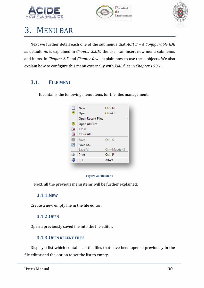
User’s Manual 30
3. MENU BAR
Next we further detail each one of the submenus that ACIDE – A Configurable IDE
as default. As is explained in Chapter 3.5.10 the user can insert new menu submenus
and items. In Chapter 3.7 and Chapter 0 we explain how to use these objects. We also
explain how to configure this menu externally with XML files in Chapter 16.3.1.
3.1. FILE MENU
It contains the following menu items for the files management:
Figure 2: File Menu
Next, all the previous menu items will be further explained:
3.1.1. NEW
Create a new empty file in the file editor.
3.1.2. OPEN
Open a previously saved file into the file editor.
3.1.3. OPEN RECENT FILES
Display a list which contains all the files that have been opened previously in the
file editor and the option to set the list to empty.
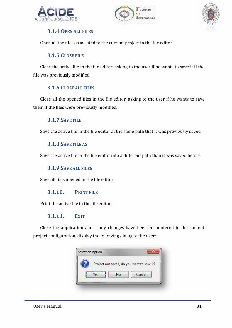
User’s Manual 31
3.1.4. OPEN ALL FILES
Open all the files associated to the current project in the file editor.
3.1.5. CLOSE FILE
Close the active file in the file editor, asking to the user if he wants to save it if the
file was previously modified.
3.1.6. CLOSE ALL FILES
Close all the opened files in the file editor, asking to the user if he wants to save
them if the files were previously modified.
3.1.7. SAVE FILE
Save the active file in the file editor at the same path that it was previously saved.
3.1.8. SAVE FILE AS
Save the active file in the file editor into a different path than it was saved before.
3.1.9. SAVE ALL FILES
Save all files opened in the file editor.
3.1.10. PRINT FILE
Print the active file in the file editor.
3.1.11. EXIT
Close the application and if any changes have been encountered in the current
project configuration, display the following dialog to the user:
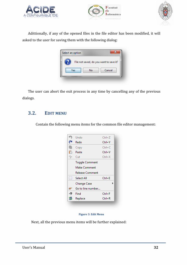
User’s Manual 32
Adittionally, if any of the opened files in the file editor has been modified, it will
asked to the user for saving them with the following dialog:
The user can abort the exit process in any time by cancelling any of the previous
dialogs.
3.2. EDIT MENU
Contain the following menu items for the common file editor management:
Figure 3: Edit Menu
Next, all the previous menu items will be further explained:
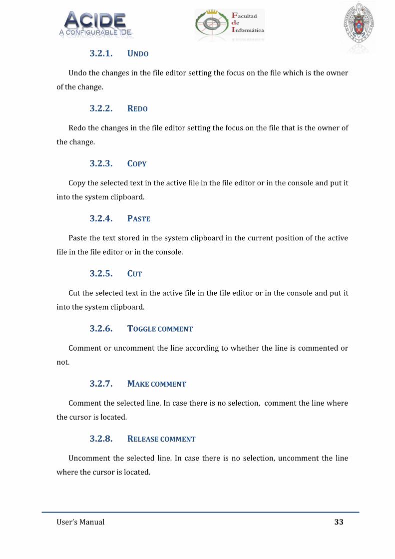
User’s Manual 33
3.2.1. UNDO
Undo the changes in the file editor setting the focus on the file which is the owner
of the change.
3.2.2. REDO
Redo the changes in the file editor setting the focus on the file that is the owner of
the change.
3.2.3. COPY
Copy the selected text in the active file in the file editor or in the console and put it
into the system clipboard.
3.2.4. PASTE
Paste the text stored in the system clipboard in the current position of the active
file in the file editor or in the console.
3.2.5. CUT
Cut the selected text in the active file in the file editor or in the console and put it
into the system clipboard.
3.2.6. TOGGLE COMMENT
Comment or uncomment the line according to whether the line is commented or
not.
3.2.7. MAKE COMMENT
Comment the selected line. In case there is no selection, comment the line where
the cursor is located.
3.2.8. RELEASE COMMENT
Uncomment the selected line. In case there is no selection, uncomment the line
where the cursor is located.
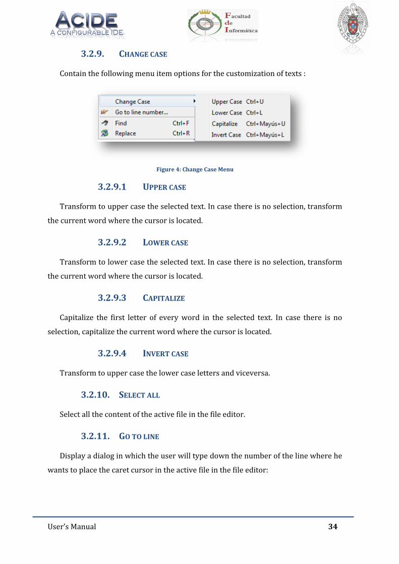
User’s Manual 34
3.2.9. CHANGE CASE
Contain the following menu item options for the customization of texts :
Figure 4: Change Case Menu
3.2.9.1 UPPER CASE
Transform to upper case the selected text. In case there is no selection, transform
the current word where the cursor is located.
3.2.9.2 LOWER CASE
Transform to lower case the selected text. In case there is no selection, transform
the current word where the cursor is located.
3.2.9.3 CAPITALIZE
Capitalize the first letter of every word in the selected text. In case there is no
selection, capitalize the current word where the cursor is located.
3.2.9.4 INVERT CASE
Transform to upper case the lower case letters and viceversa.
3.2.10. SELECT ALL
Select all the content of the active file in the file editor.
3.2.11. GO TO LINE
Display a dialog in which the user will type down the number of the line where he
wants to place the caret cursor in the active file in the file editor:
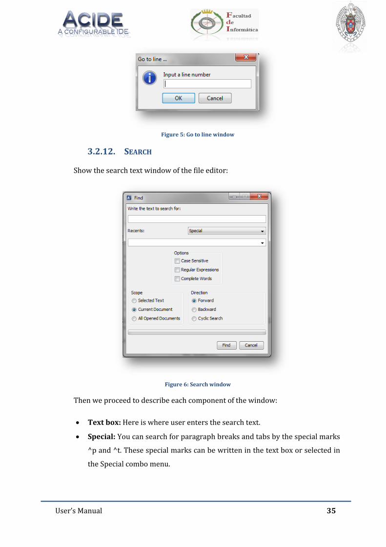
User’s Manual 35
Figure 5: Go to line window
3.2.12. SEARCH
Show the search text window of the file editor:
Figure 6: Search window
Then we proceed to describe each component of the window:
Text box: Here is where user enters the search text.
Special: You can search for paragraph breaks and tabs by the special marks
^p and ^t. These special marks can be written in the text box or selected in
the Special combo menu.
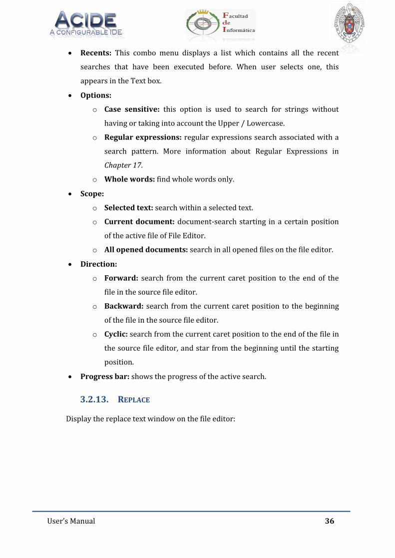
User’s Manual 36
Recents: This combo menu displays a list which contains all the recent
searches that have been executed before. When user selects one, this
appears in the Text box.
Options:
o Case sensitive: this option is used to search for strings without
having or taking into account the Upper / Lowercase.
o Regular expressions: regular expressions search associated with a
search pattern. More information about Regular Expressions in
Chapter 17.
o Whole words: find whole words only.
Scope:
o Selected text: search within a selected text.
o Current document: document-search starting in a certain position
of the active file of File Editor.
o All opened documents: search in all opened files on the file editor.
Direction:
o Forward: search from the current caret position to the end of the
file in the source file editor.
o Backward: search from the current caret position to the beginning
of the file in the source file editor.
o Cyclic: search from the current caret position to the end of the file in
the source file editor, and star from the beginning until the starting
position.
Progress bar: shows the progress of the active search.
3.2.13. REPLACE
Display the replace text window on the file editor:
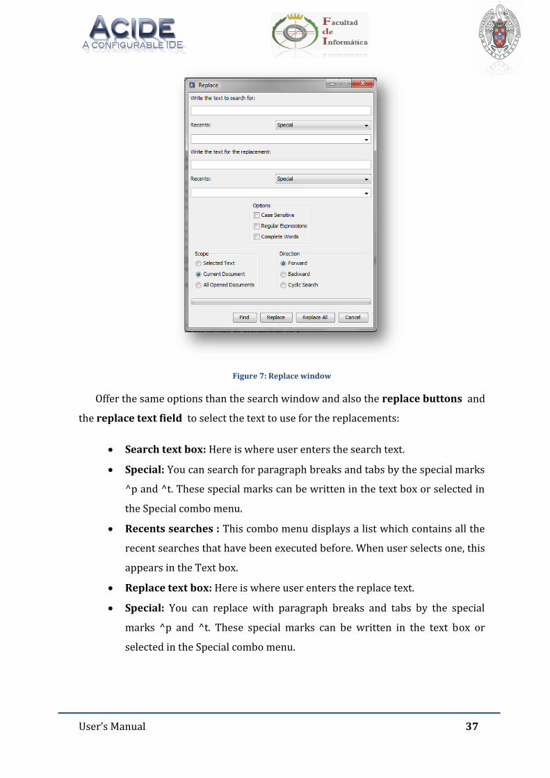
User’s Manual 37
Figure 7: Replace window
Offer the same options than the search window and also the replace buttons and
the replace text field to select the text to use for the replacements:
Search text box: Here is where user enters the search text.
Special: You can search for paragraph breaks and tabs by the special marks
^p and ^t. These special marks can be written in the text box or selected in
the Special combo menu.
Recents searches : This combo menu displays a list which contains all the
recent searches that have been executed before. When user selects one, this
appears in the Text box.
Replace text box: Here is where user enters the replace text.
Special: You can replace with paragraph breaks and tabs by the special
marks ^p and ^t. These special marks can be written in the text box or
selected in the Special combo menu.
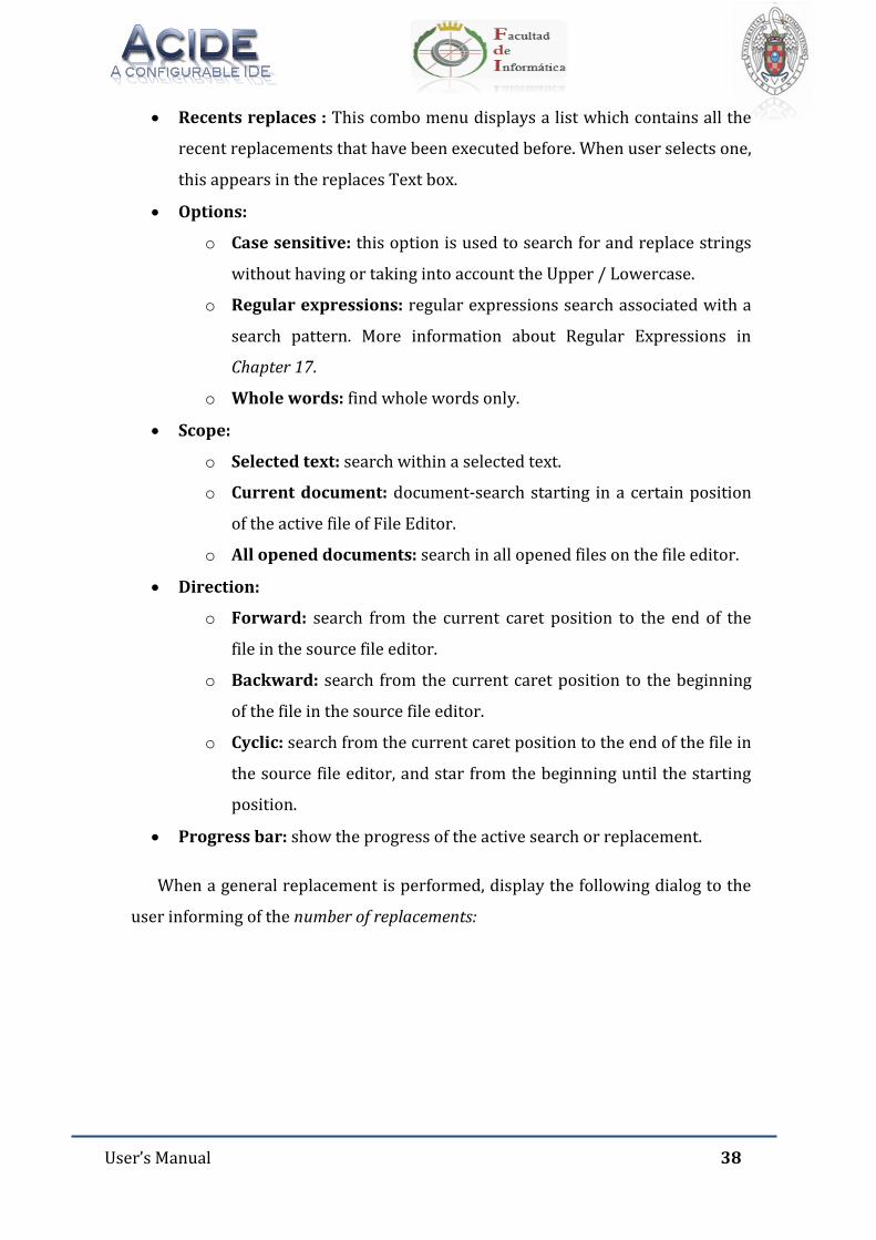
User’s Manual 38
Recents replaces : This combo menu displays a list which contains all the
recent replacements that have been executed before. When user selects one,
this appears in the replaces Text box.
Options:
o Case sensitive: this option is used to search for and replace strings
without having or taking into account the Upper / Lowercase.
o Regular expressions: regular expressions search associated with a
search pattern. More information about Regular Expressions in
Chapter 17.
o Whole words: find whole words only.
Scope:
o Selected text: search within a selected text.
o Current document: document-search starting in a certain position
of the active file of File Editor.
o All opened documents: search in all opened files on the file editor.
Direction:
o Forward: search from the current caret position to the end of the
file in the source file editor.
o Backward: search from the current caret position to the beginning
of the file in the source file editor.
o Cyclic: search from the current caret position to the end of the file in
the source file editor, and star from the beginning until the starting
position.
Progress bar: show the progress of the active search or replacement.
When a general replacement is performed, display the following dialog to the
user informing of the number of replacements:
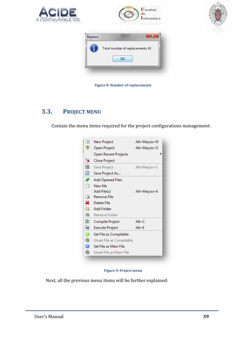
User’s Manual 39
Figure 8: Number of replacements
3.3. PROJECT MENU
Contain the menu items required for the project configurations management:
Figure 9: Project menu
Next, all the previous menu items will be further explained:
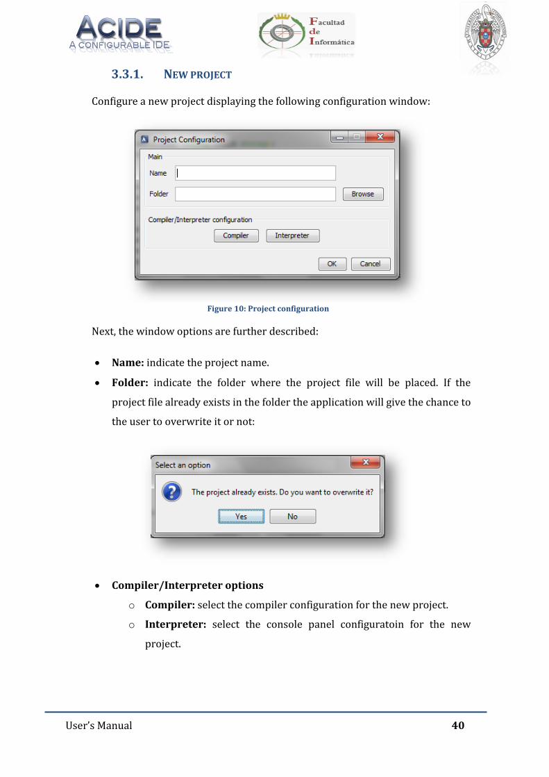
User’s Manual 40
3.3.1. NEW PROJECT
Configure a new project displaying the following configuration window:
Figure 10: Project configuration
Next, the window options are further described:
Name: indicate the project name.
Folder: indicate the folder where the project file will be placed. If the
project file already exists in the folder the application will give the chance to
the user to overwrite it or not:
Compiler/Interpreter options
o Compiler: select the compiler configuration for the new project.
o Interpreter: select the console panel configuratoin for the new
project.
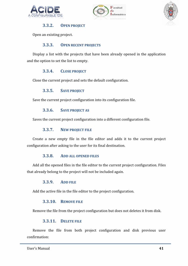
User’s Manual 41
3.3.2. OPEN PROJECT
Open an existing project.
3.3.3. OPEN RECENT PROJECTS
Display a list with the projects that have been already opened in the application
and the option to set the list to empty.
3.3.4. CLOSE PROJECT
Close the current project and sets the default configuration.
3.3.5. SAVE PROJECT
Save the current project configuration into its configuration file.
3.3.6. SAVE PROJECT AS
Saves the current project configuration into a different configuration file.
3.3.7. NEW PROJECT FILE
Create a new empty file in the file editor and adds it to the current project
configuration after asking to the user for its final destination.
3.3.8. ADD ALL OPENED FILES
Add all the opened files in the file editor to the current project configuration. Files
that already belong to the project will not be included again.
3.3.9. ADD FILE
Add the active file in the file editor to the project configuration.
3.3.10. REMOVE FILE
Remove the file from the project configuration but does not deletes it from disk.
3.3.11. DELETE FILE
Remove the file from both project configuration and disk previous user
confirmation:
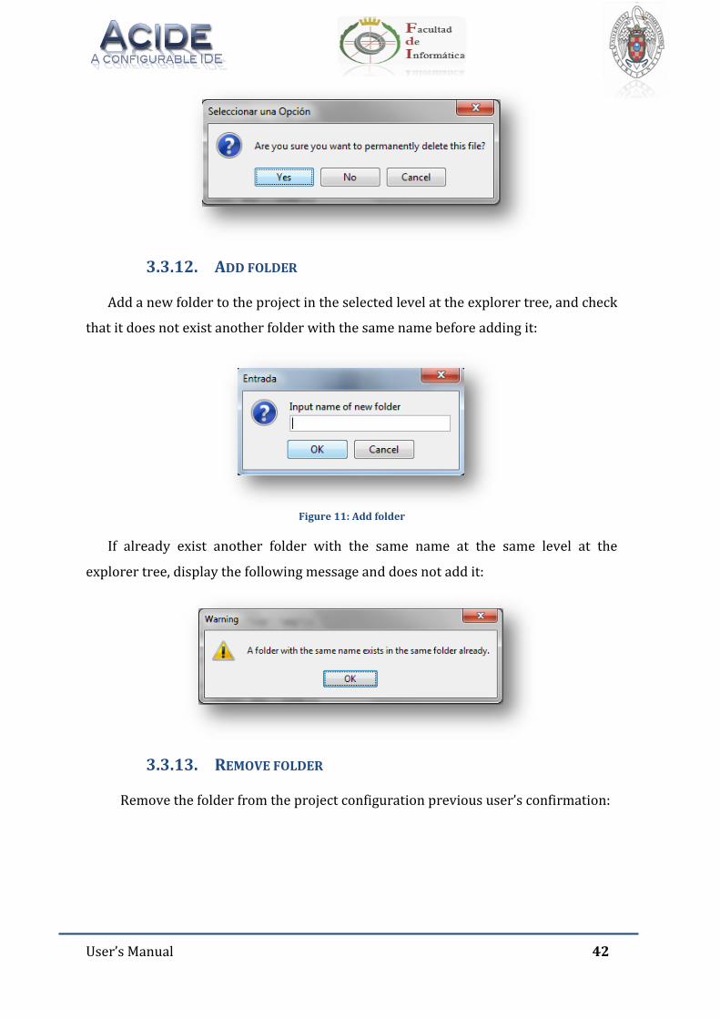
User’s Manual 42
3.3.12. ADD FOLDER
Add a new folder to the project in the selected level at the explorer tree, and check
that it does not exist another folder with the same name before adding it:
Figure 11: Add folder
If already exist another folder with the same name at the same level at the
explorer tree, display the following message and does not add it:
3.3.13. REMOVE FOLDER
Remove the folder from the project configuration previous user’s confirmation:
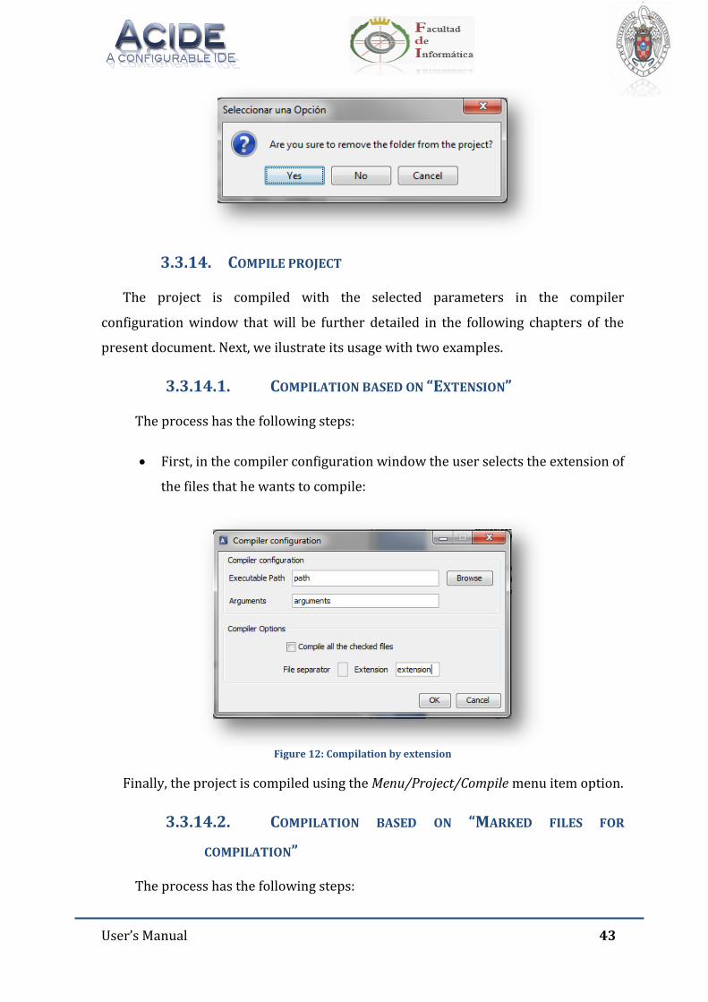
User’s Manual 43
3.3.14. COMPILE PROJECT
The project is compiled with the selected parameters in the compiler
configuration window that will be further detailed in the following chapters of the
present document. Next, we ilustrate its usage with two examples.
3.3.14.1. COMPILATION BASED ON “EXTENSION”
The process has the following steps:
First, in the compiler configuration window the user selects the extension of
the files that he wants to compile:
Figure 12: Compilation by extension
Finally, the project is compiled using the Menu/Project/Compile menu item option.
3.3.14.2. COMPILATION BASED ON “MARKED FILES FOR
COMPILATION”
The process has the following steps:
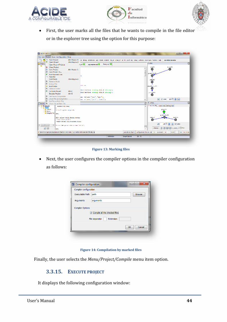
User’s Manual 44
First, the user marks all the files that he wants to compile in the file editor
or in the explorer tree using the option for this purpose:
Figure 13: Marking files
Next, the user configures the compiler options in the compiler configuration
as follows:
Figure 14: Compilation by marked files
Finally, the user selects the Menu/Project/Compile menu item option.
3.3.15. EXECUTE PROJECT
It displays the following configuration window:
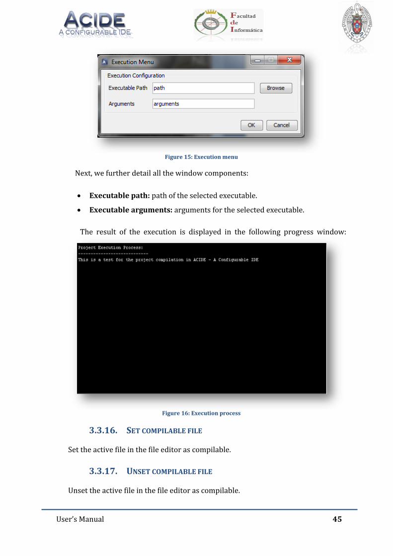
User’s Manual 45
Figure 15: Execution menu
Next, we further detail all the window components:
Executable path: path of the selected executable.
Executable arguments: arguments for the selected executable.
The result of the execution is displayed in the following progress window:
Figure 16: Execution process
3.3.16. SET COMPILABLE FILE
Set the active file in the file editor as compilable.
3.3.17. UNSET COMPILABLE FILE
Unset the active file in the file editor as compilable.
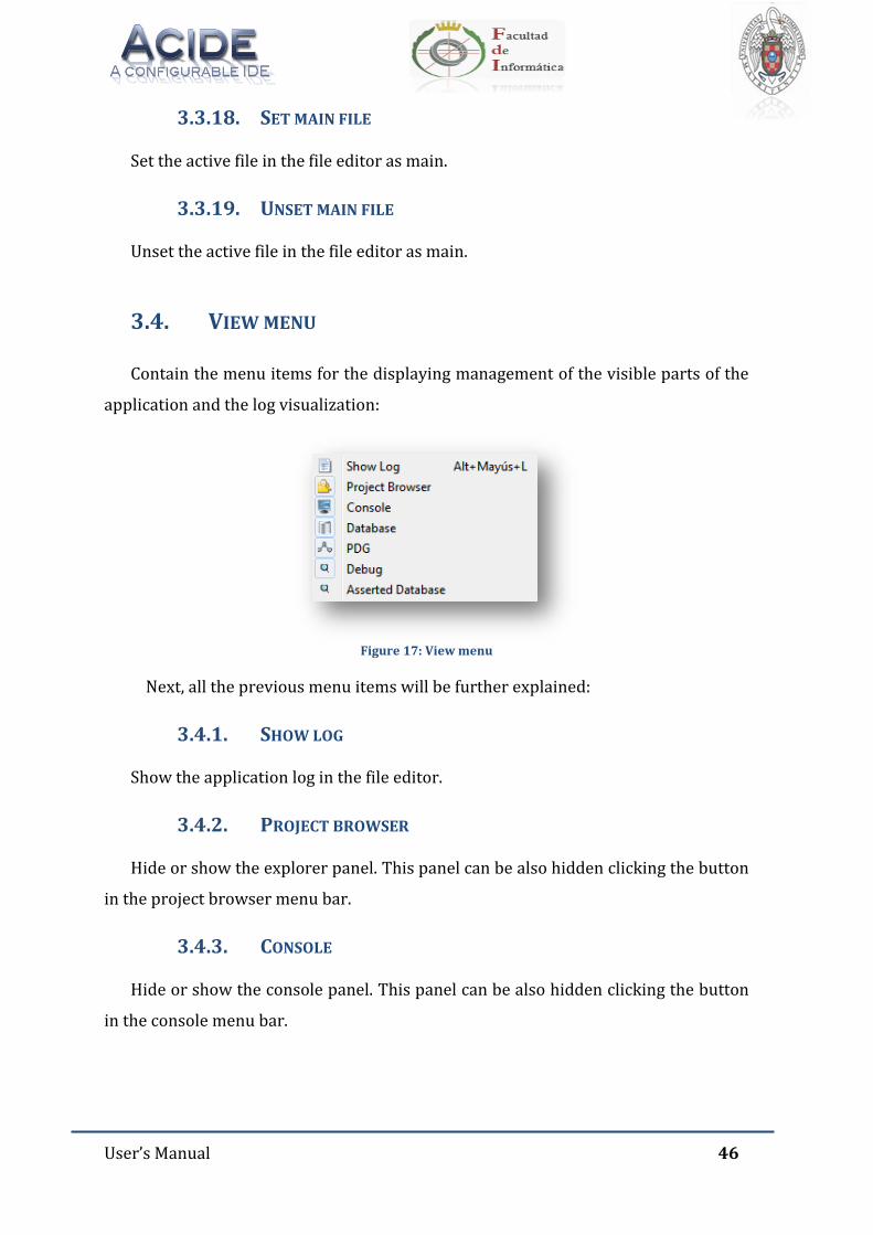
User’s Manual 46
3.3.18. SET MAIN FILE
Set the active file in the file editor as main.
3.3.19. UNSET MAIN FILE
Unset the active file in the file editor as main.
3.4. VIEW MENU
Contain the menu items for the displaying management of the visible parts of the
application and the log visualization:
Figure 17: View menu
Next, all the previous menu items will be further explained:
3.4.1. SHOW LOG
Show the application log in the file editor.
3.4.2. PROJECT BROWSER
Hide or show the explorer panel. This panel can be also hidden clicking the button
in the project browser menu bar.
3.4.3. CONSOLE
Hide or show the console panel. This panel can be also hidden clicking the button
in the console menu bar.
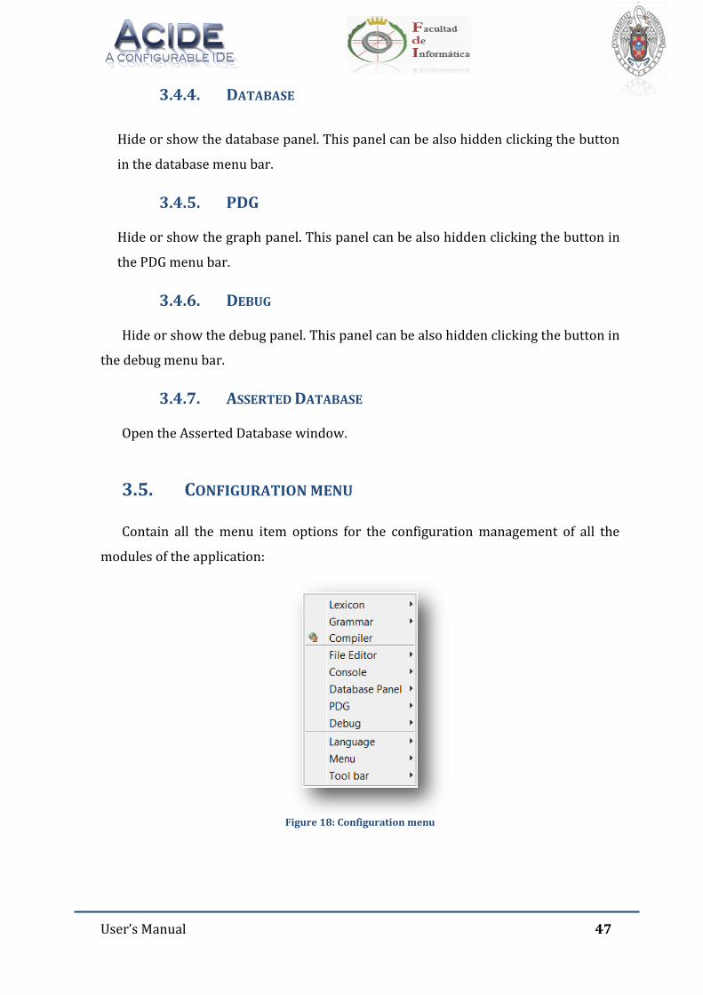
User’s Manual 47
3.4.4. DATABASE
Hide or show the database panel. This panel can be also hidden clicking the button
in the database menu bar.
3.4.5. PDG
Hide or show the graph panel. This panel can be also hidden clicking the button in
the PDG menu bar.
3.4.6. DEBUG
Hide or show the debug panel. This panel can be also hidden clicking the button in
the debug menu bar.
3.4.7. ASSERTED DATABASE
Open the Asserted Database window.
3.5. CONFIGURATION MENU
Contain all the menu item options for the configuration management of all the
modules of the application:
Figure 18: Configuration menu
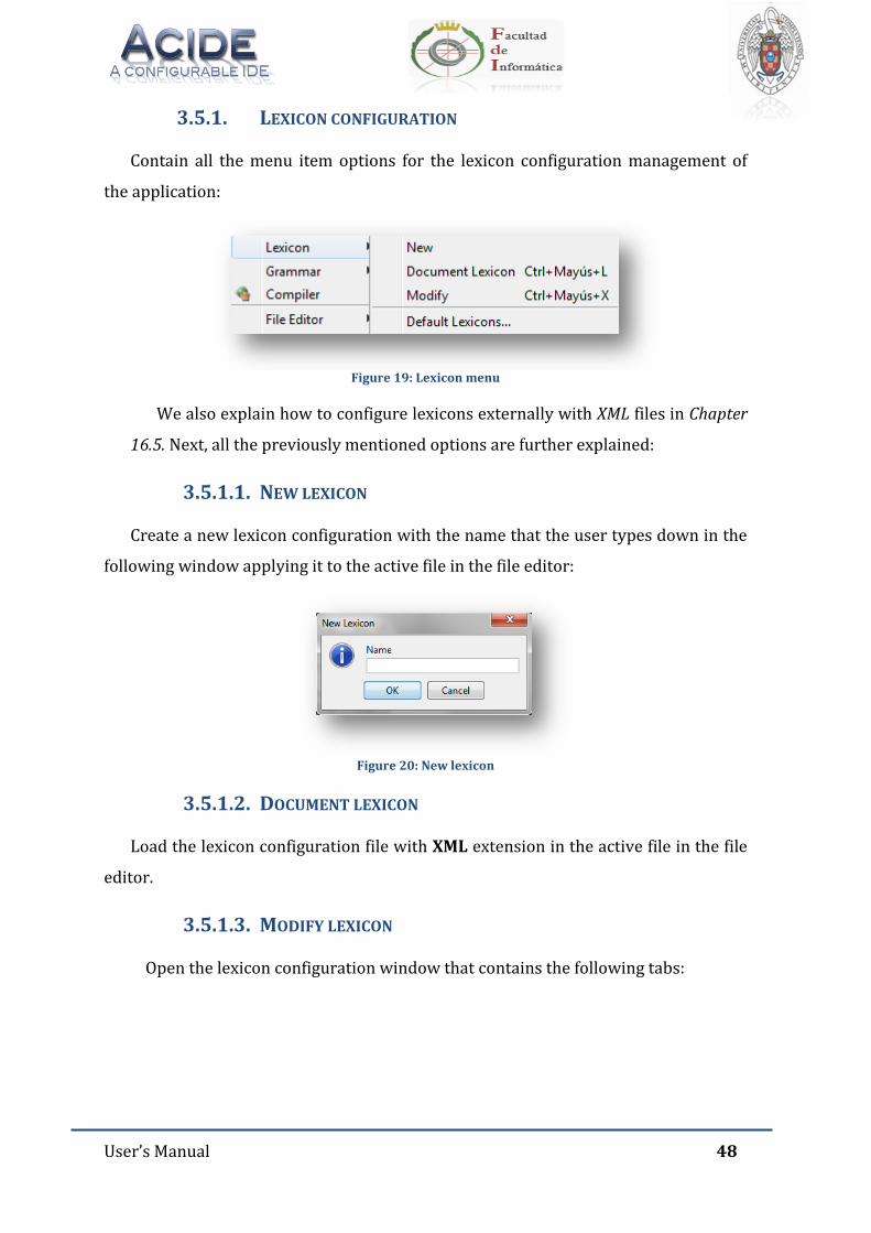
User’s Manual 48
3.5.1. LEXICON CONFIGURATION
Contain all the menu item options for the lexicon configuration management of
the application:
Figure 19: Lexicon menu
We also explain how to configure lexicons externally with XML files in Chapter
16.5. Next, all the previously mentioned options are further explained:
3.5.1.1. NEW LEXICON
Create a new lexicon configuration with the name that the user types down in the
following window applying it to the active file in the file editor:
Figure 20: New lexicon
3.5.1.2. DOCUMENT LEXICON
Load the lexicon configuration file with XML extension in the active file in the file
editor.
3.5.1.3. MODIFY LEXICON
Open the lexicon configuration window that contains the following tabs:
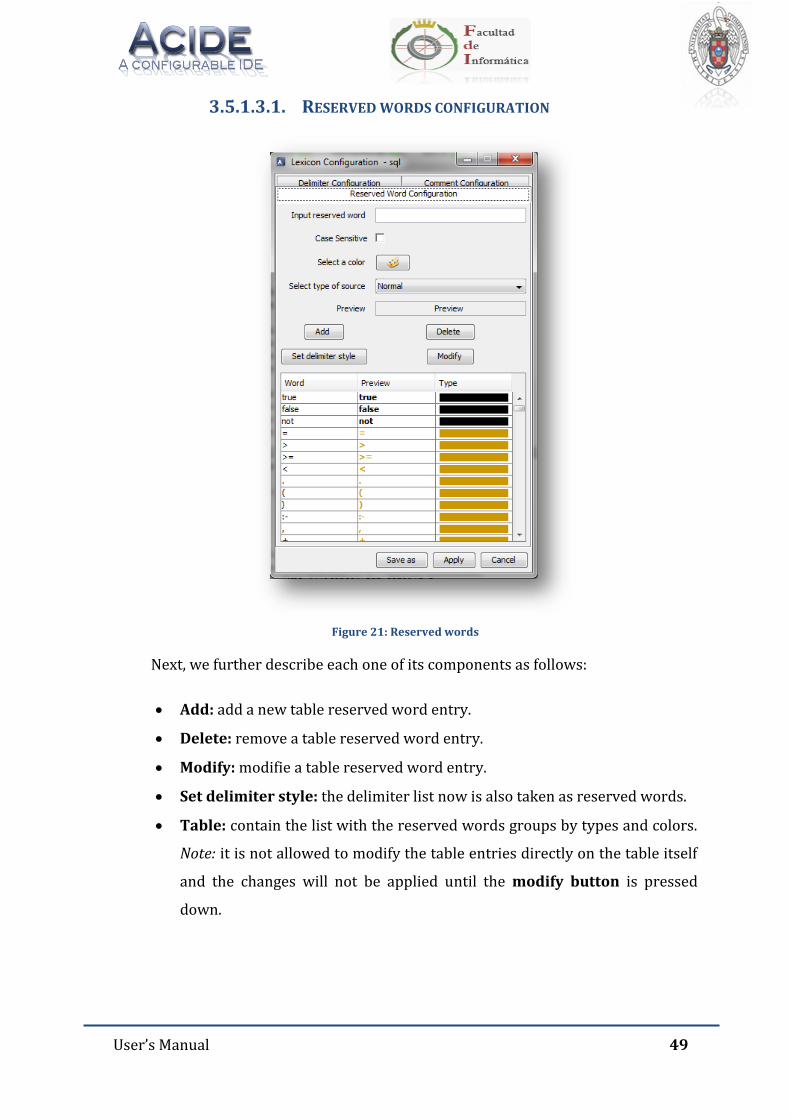
User’s Manual 49
3.5.1.3.1. RESERVED WORDS CONFIGURATION
Figure 21: Reserved words
Next, we further describe each one of its components as follows:
Add: add a new table reserved word entry.
Delete: remove a table reserved word entry.
Modify: modifie a table reserved word entry.
Set delimiter style: the delimiter list now is also taken as reserved words.
Table: contain the list with the reserved words groups by types and colors.
Note: it is not allowed to modify the table entries directly on the table itself
and the changes will not be applied until the modify button is pressed
down.
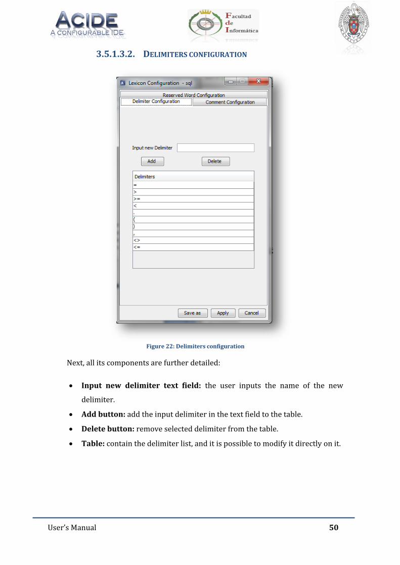
User’s Manual 50
3.5.1.3.2. DELIMITERS CONFIGURATION
Figure 22: Delimiters configuration
Next, all its components are further detailed:
Input new delimiter text field: the user inputs the name of the new
delimiter.
Add button: add the input delimiter in the text field to the table.
Delete button: remove selected delimiter from the table.
Table: contain the delimiter list, and it is possible to modify it directly on it.
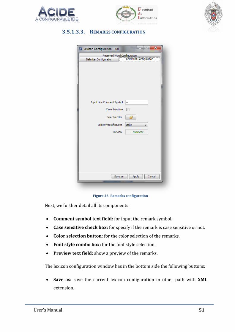
User’s Manual 51
3.5.1.3.3. REMARKS CONFIGURATION
Figure 23: Remarks configuration
Next, we further detail all its components:
Comment symbol text field: for input the remark symbol.
Case sensitive check box: for specify if the remark is case sensitive or not.
Color selection button: for the color selection of the remarks.
Font style combo box: for the font style selection.
Preview text field: show a preview of the remarks.
The lexicon configuration window has in the bottom side the following buttons:
Save as: save the current lexicon configuration in other path with XML
extension.
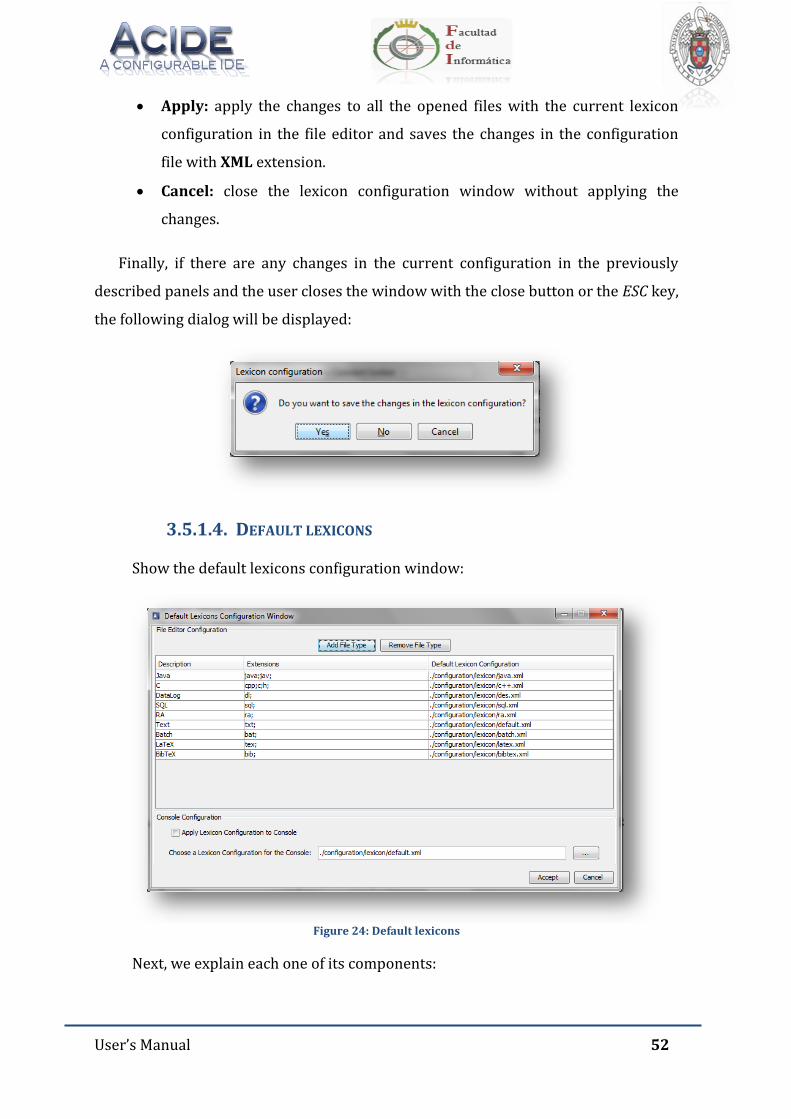
User’s Manual 52
Apply: apply the changes to all the opened files with the current lexicon
configuration in the file editor and saves the changes in the configuration
file with XML extension.
Cancel: close the lexicon configuration window without applying the
changes.
Finally, if there are any changes in the current configuration in the previously
described panels and the user closes the window with the close button or the ESC key,
the following dialog will be displayed:
3.5.1.4. DEFAULT LEXICONS
Show the default lexicons configuration window:
Figure 24: Default lexicons
Next, we explain each one of its components:
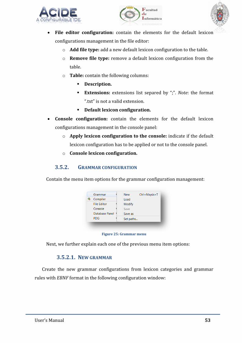
User’s Manual 53
File editor configuration: contain the elements for the default lexicon
configurations management in the file editor:
o Add file type: add a new default lexicon configuration to the table.
o Remove file type: remove a default lexicon configuration from the
table.
o Table: contain the following columns:
Description.
Extensions: extensions list separed by “;”. Note: the format
“.txt” is not a valid extension.
Default lexicon configuration.
Console configuration: contain the elements for the default lexicon
configurations management in the console panel:
o Apply lexicon configuration to the console: indicate if the default
lexicon configuration has to be applied or not to the console panel.
o Console lexicon configuration.
3.5.2. GRAMMAR CONFIGURATION
Contain the menu item options for the grammar configuration management:
Figure 25: Grammar menu
Next, we further explain each one of the previous menu item options:
3.5.2.1. NEW GRAMMAR
Create the new grammar configurations from lexicon categories and grammar
rules with EBNF format in the following configuration window:
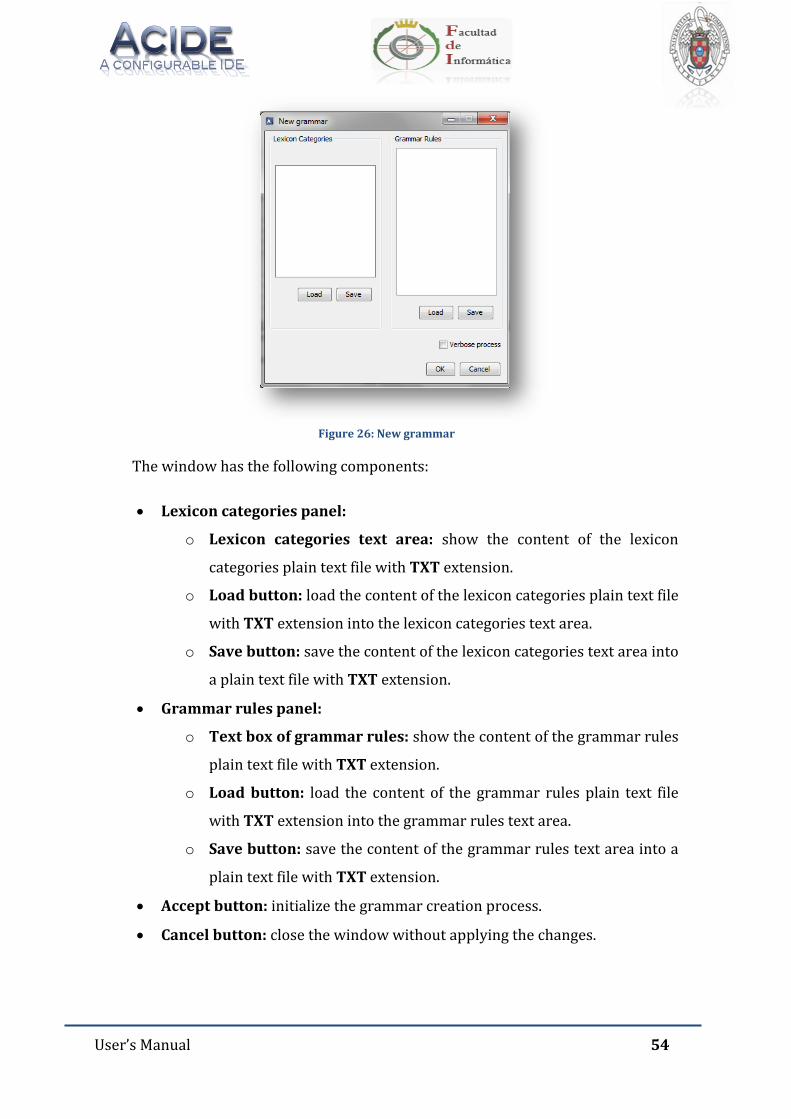
User’s Manual 54
Figure 26: New grammar
The window has the following components:
Lexicon categories panel:
o Lexicon categories text area: show the content of the lexicon
categories plain text file with TXT extension.
o Load button: load the content of the lexicon categories plain text file
with TXT extension into the lexicon categories text area.
o Save button: save the content of the lexicon categories text area into
a plain text file with TXT extension.
Grammar rules panel:
o Text box of grammar rules: show the content of the grammar rules
plain text file with TXT extension.
o Load button: load the content of the grammar rules plain text file
with TXT extension into the grammar rules text area.
o Save button: save the content of the grammar rules text area into a
plain text file with TXT extension.
Accept button: initialize the grammar creation process.
Cancel button: close the window without applying the changes.
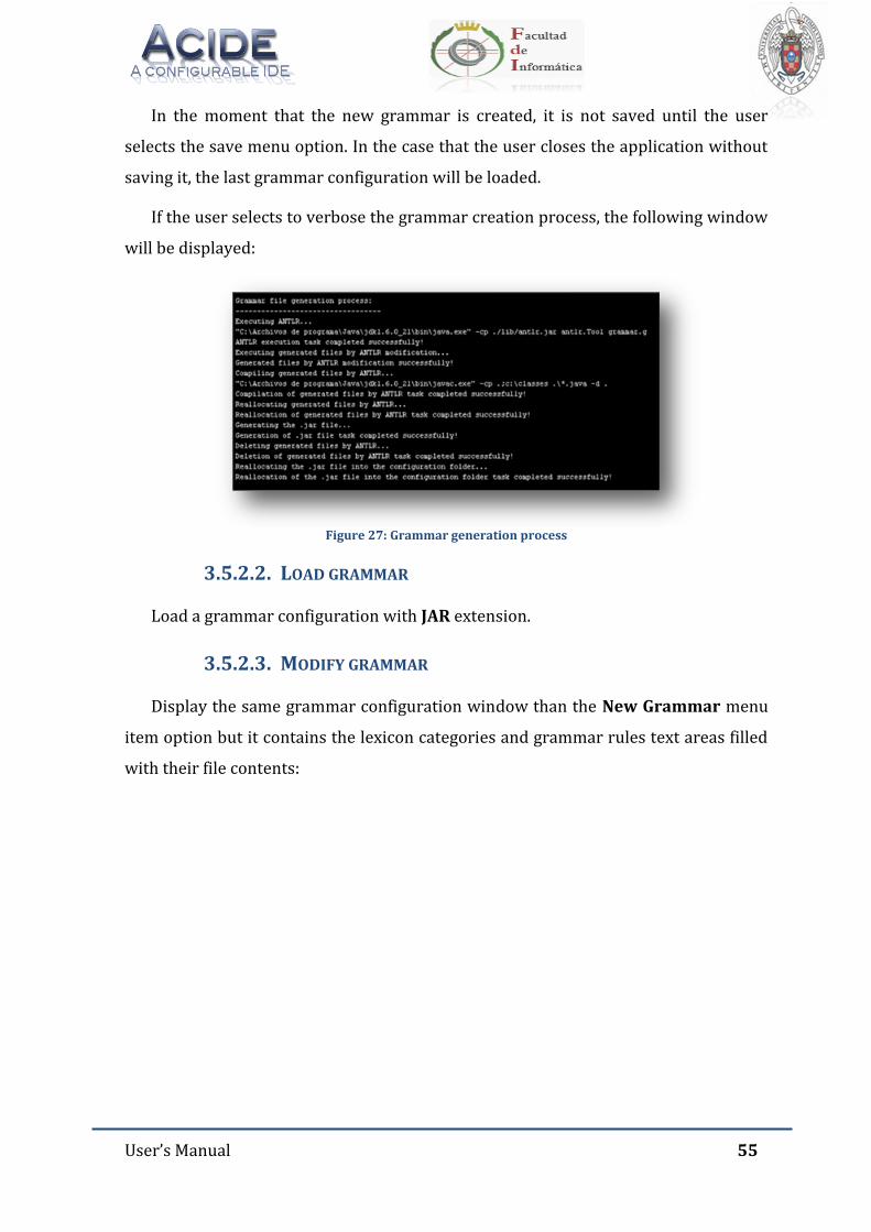
User’s Manual 55
In the moment that the new grammar is created, it is not saved until the user
selects the save menu option. In the case that the user closes the application without
saving it, the last grammar configuration will be loaded.
If the user selects to verbose the grammar creation process, the following window
will be displayed:
Figure 27: Grammar generation process
3.5.2.2. LOAD GRAMMAR
Load a grammar configuration with JAR extension.
3.5.2.3. MODIFY GRAMMAR
Display the same grammar configuration window than the New Grammar menu
item option but it contains the lexicon categories and grammar rules text areas filled
with their file contents:
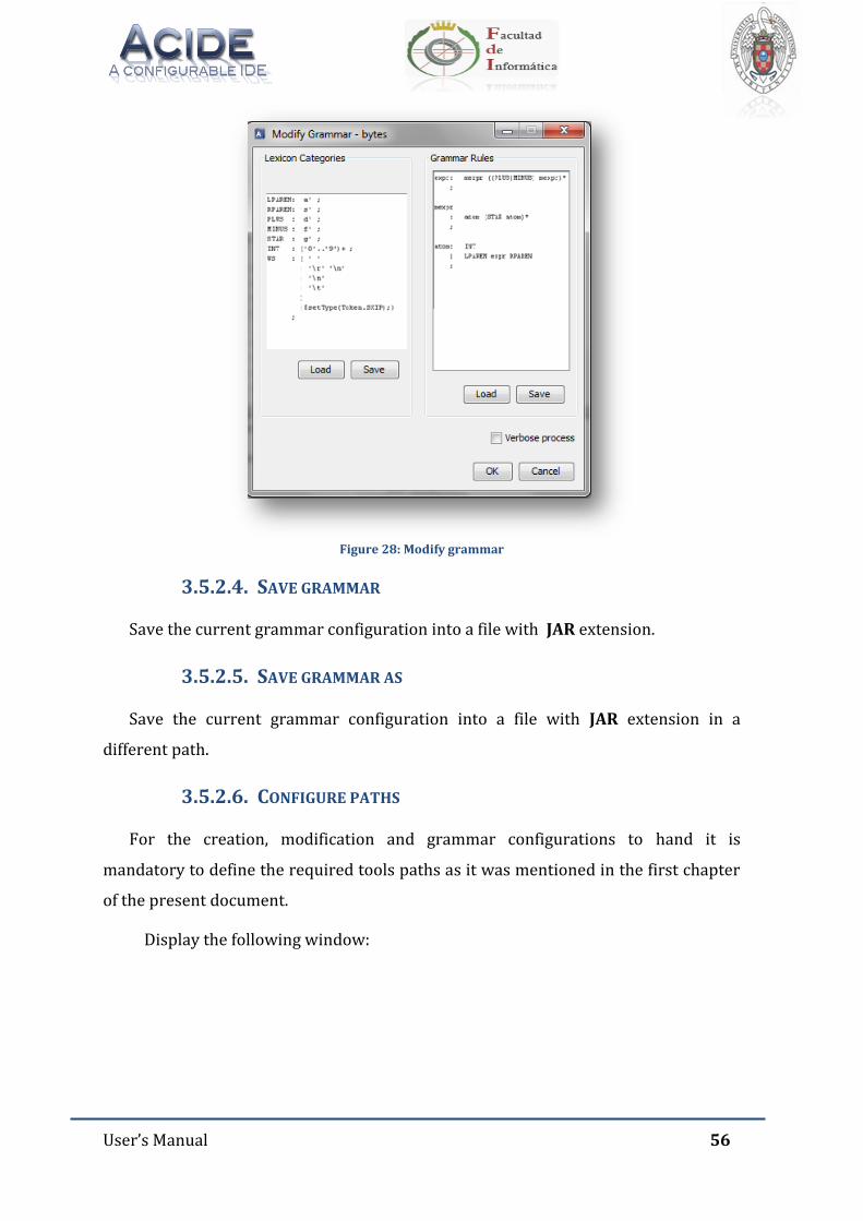
User’s Manual 56
Figure 28: Modify grammar
3.5.2.4. SAVE GRAMMAR
Save the current grammar configuration into a file with JAR extension.
3.5.2.5. SAVE GRAMMAR AS
Save the current grammar configuration into a file with JAR extension in a
different path.
3.5.2.6. CONFIGURE PATHS
For the creation, modification and grammar configurations to hand it is
mandatory to define the required tools paths as it was mentioned in the first chapter
of the present document.
Display the following window:
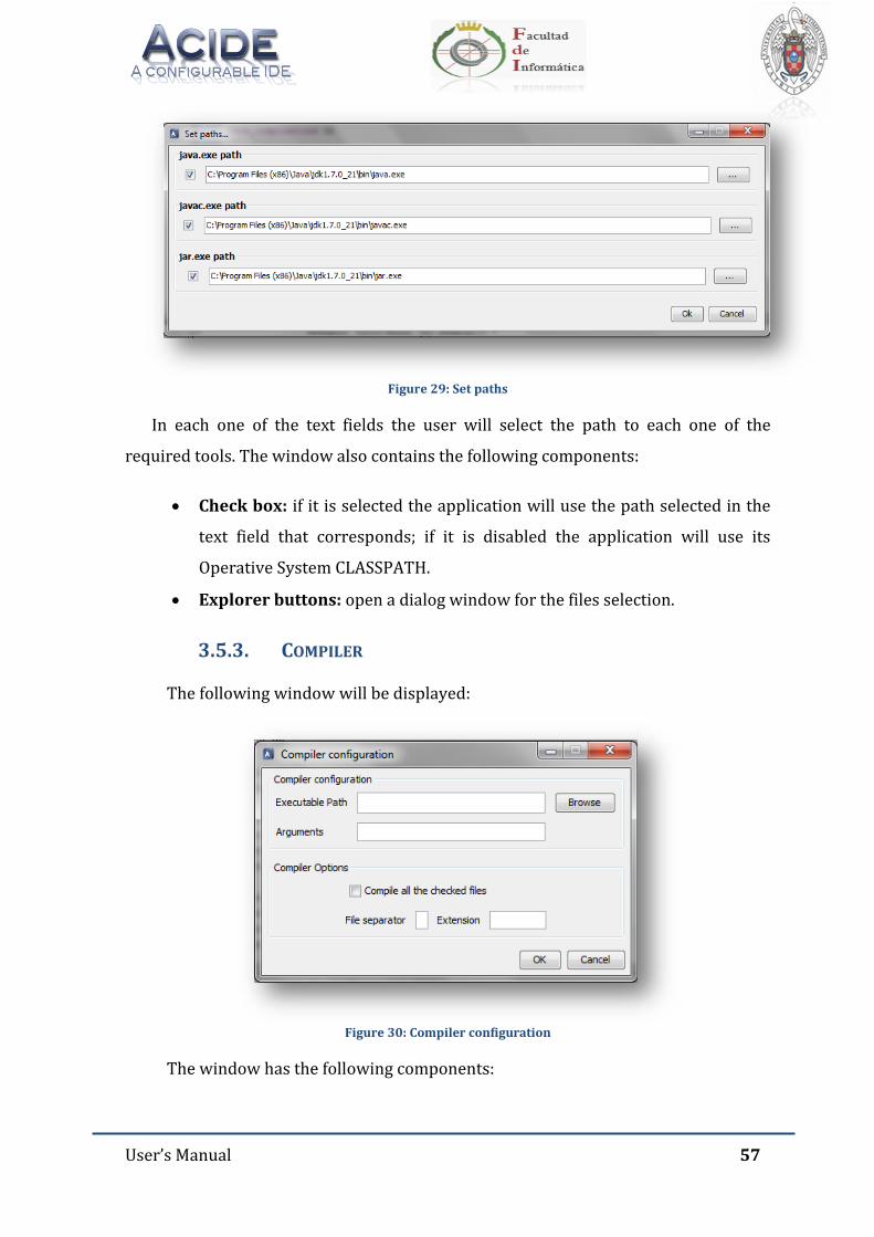
User’s Manual 57
Figure 29: Set paths
In each one of the text fields the user will select the path to each one of the
required tools. The window also contains the following components:
Check box: if it is selected the application will use the path selected in the
text field that corresponds; if it is disabled the application will use its
Operative System CLASSPATH.
Explorer buttons: open a dialog window for the files selection.
3.5.3. COMPILER
The following window will be displayed:
Figure 30: Compiler configuration
The window has the following components:
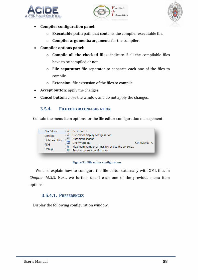
User’s Manual 58
Compiler configuration panel:
o Executable path: path that contains the compiler executable file.
o Compiler arguments: arguments for the compiler.
Compiler options panel:
o Compile all the checked files: indicate if all the compilable files
have to be compiled or not.
o File separator: file separator to separate each one of the files to
compile.
o Extension: file extension of the files to compile.
Accept button: apply the changes.
Cancel button: close the window and do not apply the changes.
3.5.4. FILE EDITOR CONFIGURATION
Contain the menu item options for the file editor configuration management:
Figure 31: File editor configuration
We also explain how to configure the file editor externally with XML files in
Chapter 16.3.3. Next, we further detail each one of the previous menu item
options:
3.5.4.1. PREFERENCES
Display the following configuration window:
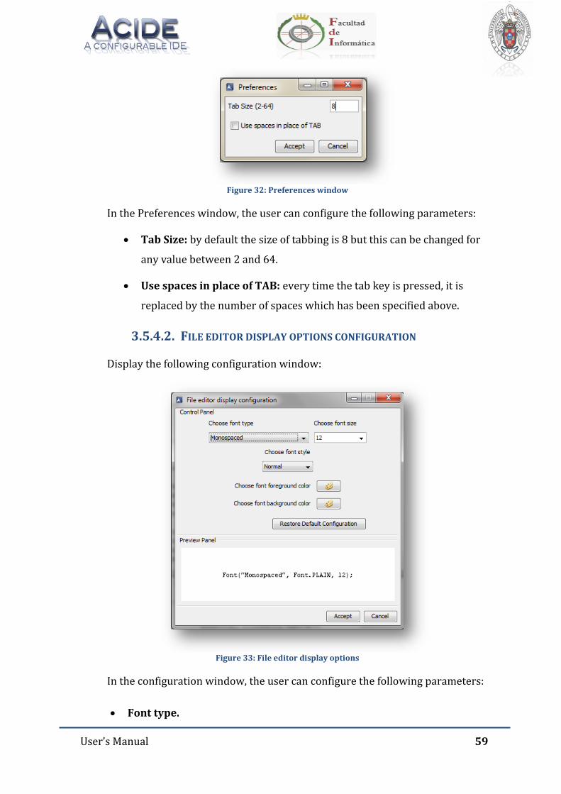
User’s Manual 59
Figure 32: Preferences window
In the Preferences window, the user can configure the following parameters:
Tab Size: by default the size of tabbing is 8 but this can be changed for
any value between 2 and 64.
Use spaces in place of TAB: every time the tab key is pressed, it is
replaced by the number of spaces which has been specified above.
3.5.4.2. FILE EDITOR DISPLAY OPTIONS CONFIGURATION
Display the following configuration window:
Figure 33: File editor display options
In the configuration window, the user can configure the following parameters:
Font type.
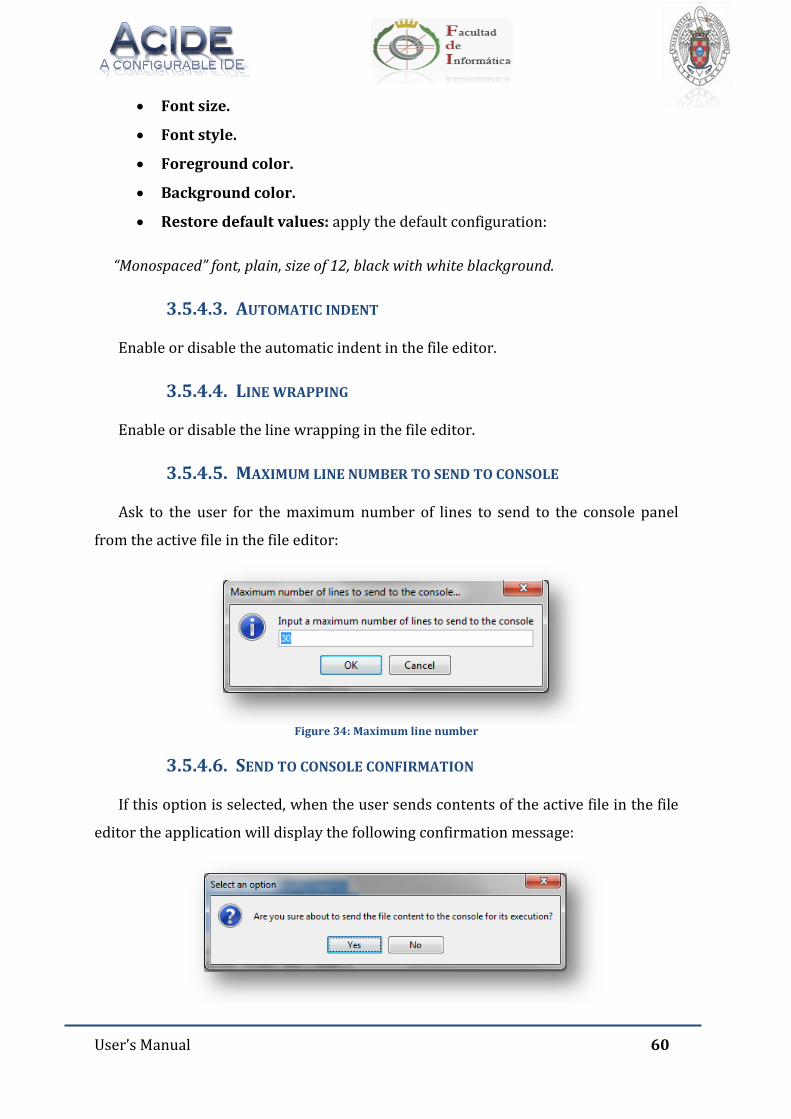
User’s Manual 60
Font size.
Font style.
Foreground color.
Background color.
Restore default values: apply the default configuration:
“Monospaced” font, plain, size of 12, black with white blackground.
3.5.4.3. AUTOMATIC INDENT
Enable or disable the automatic indent in the file editor.
3.5.4.4. LINE WRAPPING
Enable or disable the line wrapping in the file editor.
3.5.4.5. MAXIMUM LINE NUMBER TO SEND TO CONSOLE
Ask to the user for the maximum number of lines to send to the console panel
from the active file in the file editor:
Figure 34: Maximum line number
3.5.4.6. SEND TO CONSOLE CONFIRMATION
If this option is selected, when the user sends contents of the active file in the file
editor the application will display the following confirmation message:
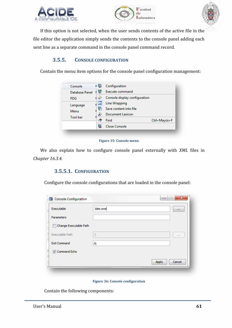
User’s Manual 61
If this option is not selected, when the user sends contents of the active file in the
file editor the application simply sends the contents to the console panel adding each
sent line as a separate command in the console panel command record.
3.5.5. CONSOLE CONFIGURATION
Contain the menu item options for the console panel configuration management:
Figure 35: Console menu
We also explain how to configure console panel externally with XML files in
Chapter 16.3.4.
3.5.5.1. CONFIGURATION
Configure the console configurations that are loaded in the console panel:
Figure 36: Console configuration
Contain the following components:
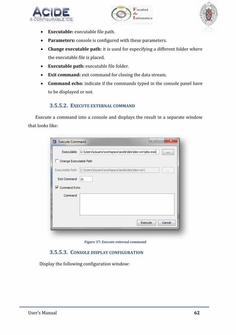
User’s Manual 62
Executable: executable file path.
Parameters: console is configured with these parameters.
Change executable path: it is used for especifying a different folder where
the executable file is placed.
Executable path: executable file folder.
Exit command: exit command for closing the data stream.
Command echo: indicate if the commands typed in the console panel have
to be displayed or not.
3.5.5.2. EXECUTE EXTERNAL COMMAND
Execute a command into a console and displays the result in a separate window
that looks like:
Figure 37: Execute external command
3.5.5.3. CONSOLE DISPLAY CONFIGURATION
Display the following configuration window:
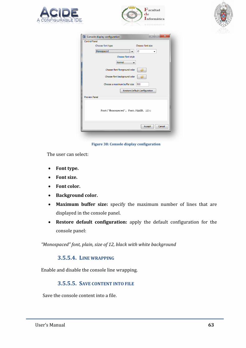
User’s Manual 63
Figure 38: Console display configuration
The user can select:
Font type.
Font size.
Font color.
Background color.
Maximum buffer size: specify the maximum number of lines that are
displayed in the console panel.
Restore default configuration: apply the default configuration for the
console panel:
“Monospaced” font, plain, size of 12, black with white background
3.5.5.4. LINE WRAPPING
Enable and disable the console line wrapping.
3.5.5.5. SAVE CONTENT INTO FILE
Save the console content into a file.
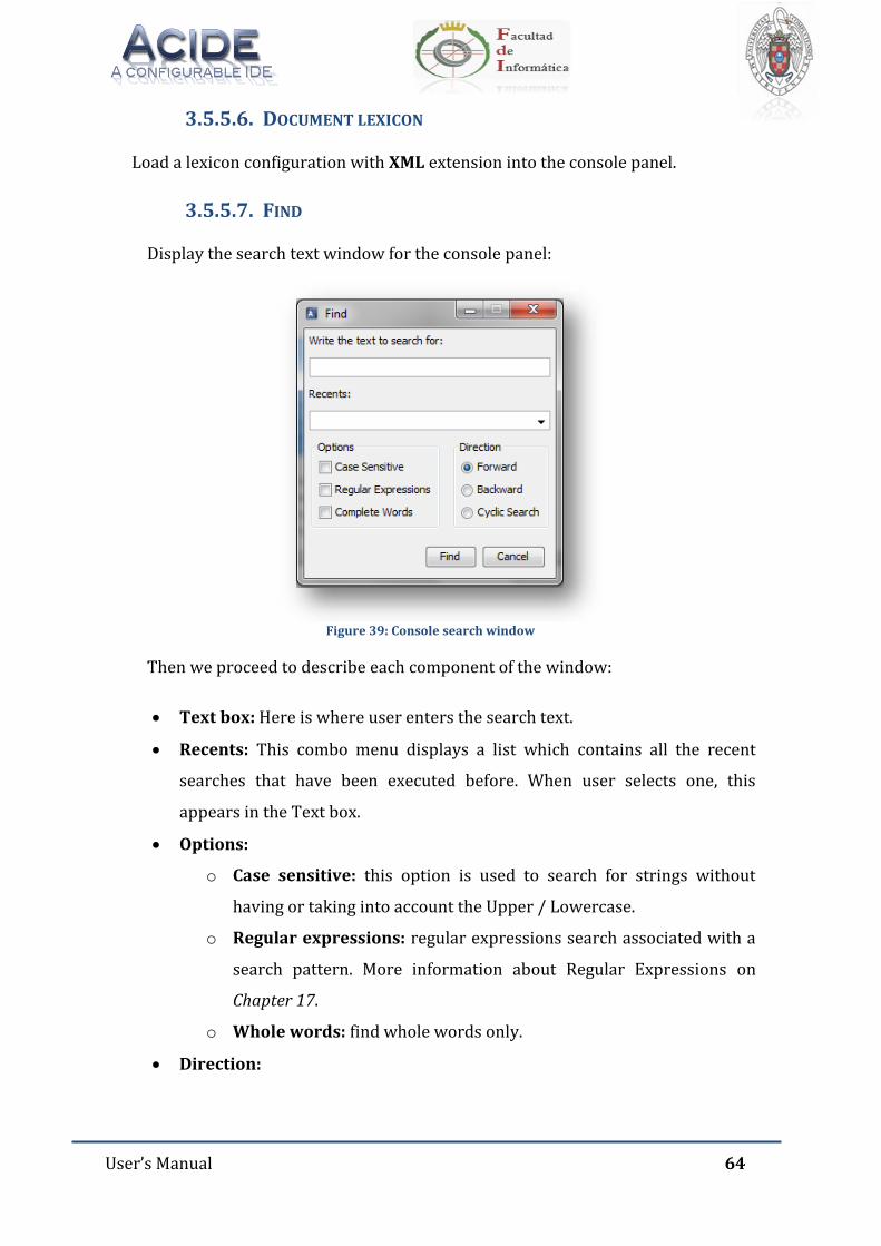
User’s Manual 64
3.5.5.6. DOCUMENT LEXICON
Load a lexicon configuration with XML extension into the console panel.
3.5.5.7. FIND
Display the search text window for the console panel:
Figure 39: Console search window
Then we proceed to describe each component of the window:
Text box: Here is where user enters the search text.
Recents: This combo menu displays a list which contains all the recent
searches that have been executed before. When user selects one, this
appears in the Text box.
Options:
o Case sensitive: this option is used to search for strings without
having or taking into account the Upper / Lowercase.
o Regular expressions: regular expressions search associated with a
search pattern. More information about Regular Expressions on
Chapter 17.
o Whole words: find whole words only.
Direction:
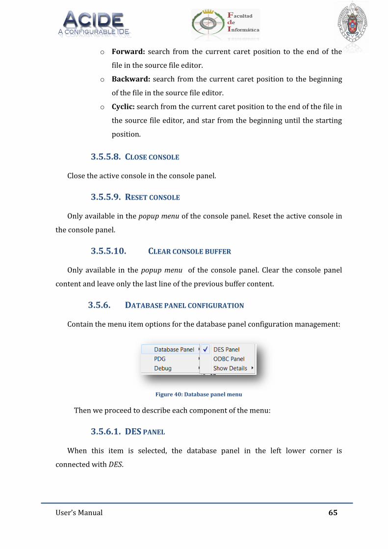
User’s Manual 65
o Forward: search from the current caret position to the end of the
file in the source file editor.
o Backward: search from the current caret position to the beginning
of the file in the source file editor.
o Cyclic: search from the current caret position to the end of the file in
the source file editor, and star from the beginning until the starting
position.
3.5.5.8. CLOSE CONSOLE
Close the active console in the console panel.
3.5.5.9. RESET CONSOLE
Only available in the popup menu of the console panel. Reset the active console in
the console panel.
3.5.5.10. CLEAR CONSOLE BUFFER
Only available in the popup menu of the console panel. Clear the console panel
content and leave only the last line of the previous buffer content.
3.5.6. DATABASE PANEL CONFIGURATION
Contain the menu item options for the database panel configuration management:
Figure 40: Database panel menu
Then we proceed to describe each component of the menu:
3.5.6.1. DES PANEL
When this item is selected, the database panel in the left lower corner is
connected with DES.
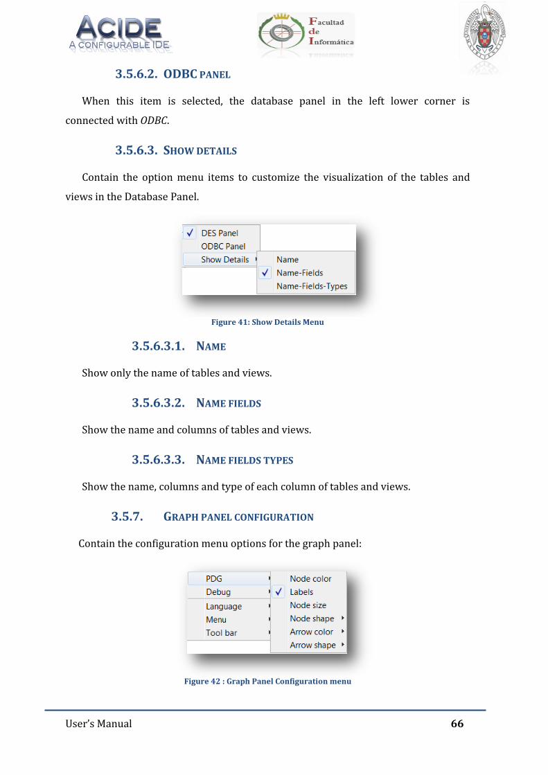
User’s Manual 66
3.5.6.2. ODBC PANEL
When this item is selected, the database panel in the left lower corner is
connected with ODBC.
3.5.6.3. SHOW DETAILS
Contain the option menu items to customize the visualization of the tables and
views in the Database Panel.
Figure 41: Show Details Menu
3.5.6.3.1. NAME
Show only the name of tables and views.
3.5.6.3.2. NAME FIELDS
Show the name and columns of tables and views.
3.5.6.3.3. NAME FIELDS TYPES
Show the name, columns and type of each column of tables and views.
3.5.7. GRAPH PANEL CONFIGURATION
Contain the configuration menu options for the graph panel:
Figure 42 : Graph Panel Configuration menu
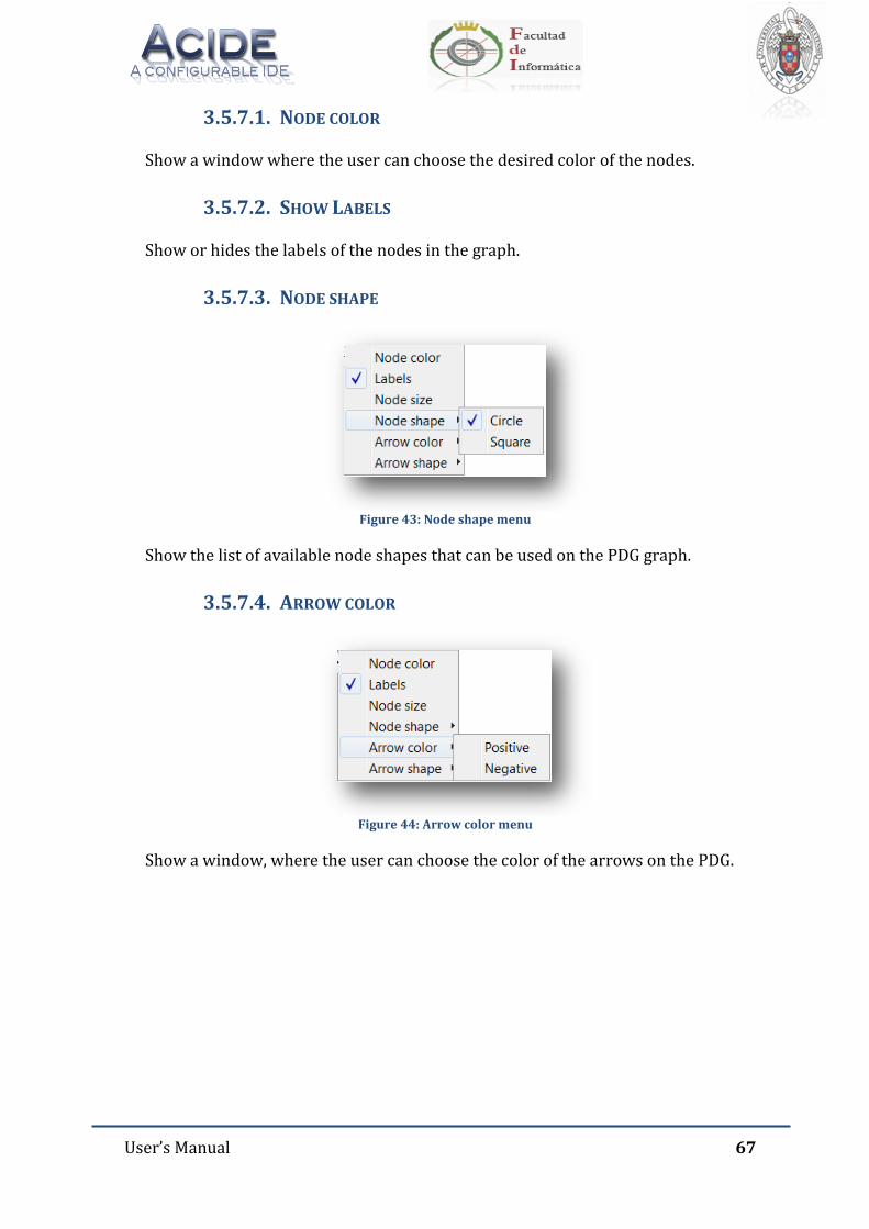
User’s Manual 67
3.5.7.1. NODE COLOR
Show a window where the user can choose the desired color of the nodes.
3.5.7.2. SHOW LABELS
Show or hides the labels of the nodes in the graph.
3.5.7.3. NODE SHAPE
Figure 43: Node shape menu
Show the list of available node shapes that can be used on the PDG graph.
3.5.7.4. ARROW COLOR
Figure 44: Arrow color menu
Show a window, where the user can choose the color of the arrows on the PDG.
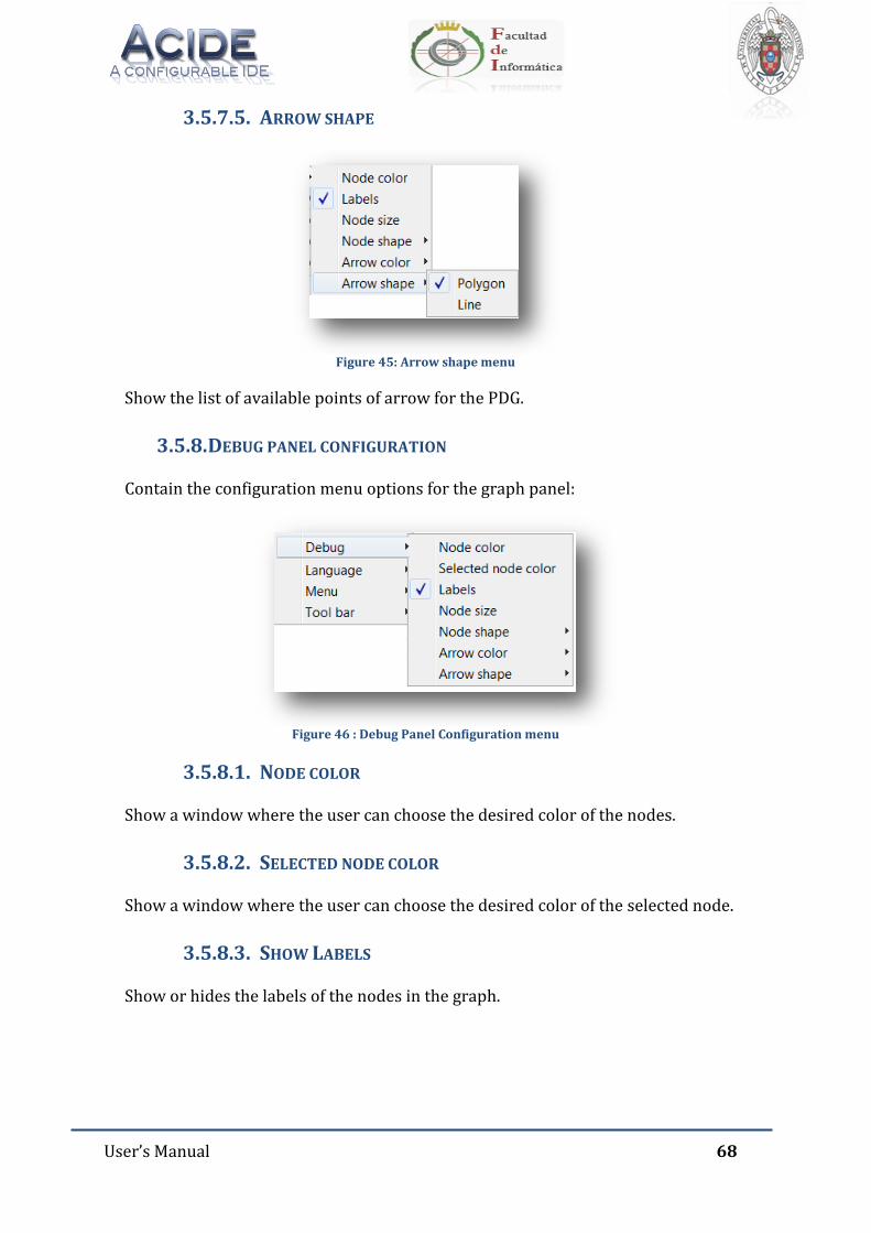
User’s Manual 68
3.5.7.5. ARROW SHAPE
Figure 45: Arrow shape menu
Show the list of available points of arrow for the PDG.
3.5.8. DEBUG PANEL CONFIGURATION
Contain the configuration menu options for the graph panel:
Figure 46 : Debug Panel Configuration menu
3.5.8.1. NODE COLOR
Show a window where the user can choose the desired color of the nodes.
3.5.8.2. SELECTED NODE COLOR
Show a window where the user can choose the desired color of the selected node.
3.5.8.3. SHOW LABELS
Show or hides the labels of the nodes in the graph.
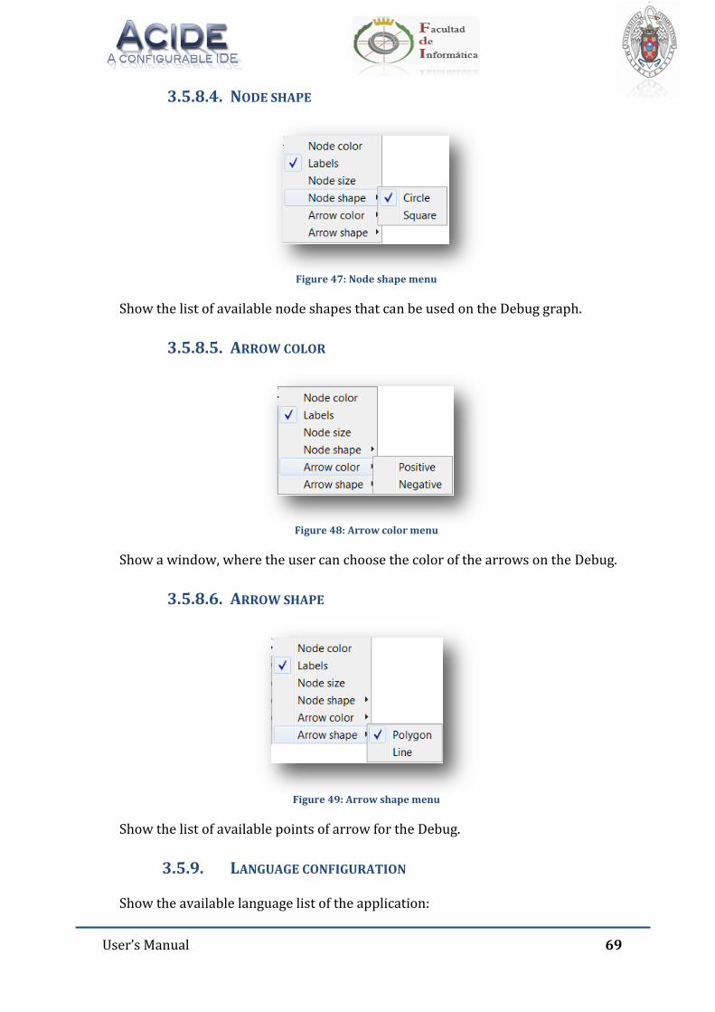
User’s Manual 69
3.5.8.4. NODE SHAPE
Figure 47: Node shape menu
Show the list of available node shapes that can be used on the Debug graph.
3.5.8.5. ARROW COLOR
Figure 48: Arrow color menu
Show a window, where the user can choose the color of the arrows on the Debug.
3.5.8.6. ARROW SHAPE
Figure 49: Arrow shape menu
Show the list of available points of arrow for the Debug.
3.5.9. LANGUAGE CONFIGURATION
Show the available language list of the application:
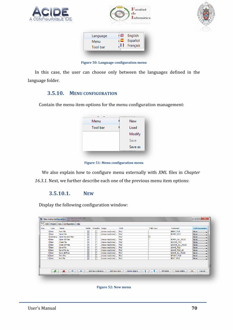
User’s Manual 70
Figure 50: Language configuration menu
In this case, the user can choose only between the languages defined in the
language folder.
3.5.10. MENU CONFIGURATION
Contain the menu item options for the menu configuration management:
Figure 51: Menu configuration menu
We also explain how to configure menu externally with XML files in Chapter
16.3.1. Next, we further describe each one of the previous menu item options:
3.5.10.1. NEW
Display the following configuration window:
Figure 52: New menu
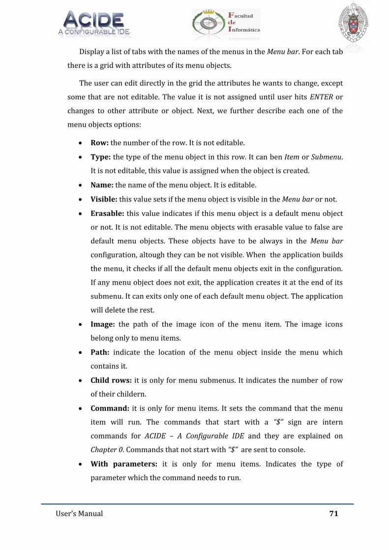
User’s Manual 71
Display a list of tabs with the names of the menus in the Menu bar. For each tab
there is a grid with attributes of its menu objects.
The user can edit directly in the grid the attributes he wants to change, except
some that are not editable. The value it is not assigned until user hits ENTER or
changes to other attribute or object. Next, we further describe each one of the
menu objects options:
Row: the number of the row. It is not editable.
Type: the type of the menu object in this row. It can ben Item or Submenu.
It is not editable, this value is assigned when the object is created.
Name: the name of the menu object. It is editable.
Visible: this value sets if the menu object is visible in the Menu bar or not.
Erasable: this value indicates if this menu object is a default menu object
or not. It is not editable. The menu objects with erasable value to false are
default menu objects. These objects have to be always in the Menu bar
configuration, altough they can be not visible. When the application builds
the menu, it checks if all the default menu objects exit in the configuration.
If any menu object does not exit, the application creates it at the end of its
submenu. It can exits only one of each default menu object. The application
will delete the rest.
Image: the path of the image icon of the menu item. The image icons
belong only to menu items.
Path: indicate the location of the menu object inside the menu which
contains it.
Child rows: it is only for menu submenus. It indicates the number of row
of their childern.
Command: it is only for menu items. It sets the command that the menu
item will run. The commands that start with a “$” sign are intern
commands for ACIDE – A Configurable IDE and they are explained on
Chapter 0. Commands that not start with “$” are sent to console.
With parameters: it is only for menu items. Indicates the type of
parameter which the command needs to run.
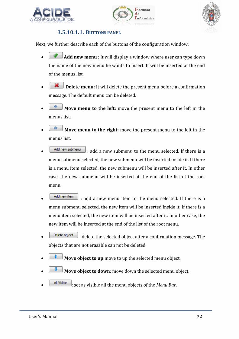
User’s Manual 72
3.5.10.1.1. BUTTONS PANEL
Next, we further describe each of the buttons of the configuration window:
Add new menu : It will display a window where user can type down
the name of the new menu he wants to insert. It will be inserted at the end
of the menus list.
Delete menu: It will delete the present menu before a confirmation
message. The default menu can be deleted.
Move menu to the left: move the present menu to the left in the
menus list.
Move menu to the right: move the present menu to the left in the
menus list.
: add a new submenu to the menu selected. If there is a
menu submenu selected, the new submenu will be inserted inside it. If there
is a menu item selected, the new submenu will be inserted after it. In other
case, the new submenu will be inserted at the end of the list of the root
menu.
: add a new menu item to the menu selected. If there is a
menu submenu selected, the new item will be inserted inside it. If there is a
menu item selected, the new item will be inserted after it. In other case, the
new item will be inserted at the end of the list of the root menu.
: delete the selected object after a confirmation message. The
objects that are not erasable can not be deleted.
Move object to up:move to up the selected menu object.
Move object to down: move down the selected menu object.
: set as visible all the menu objects of the Menu Bar.
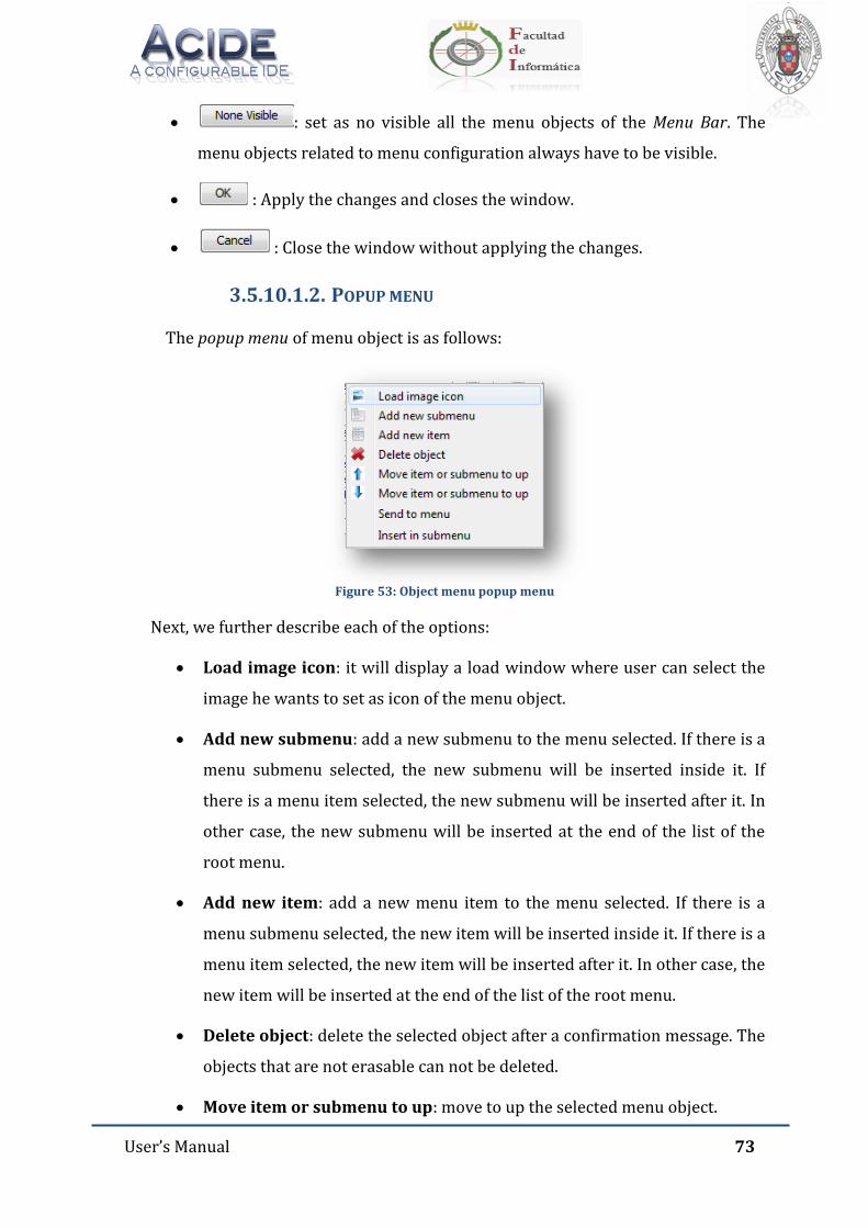
User’s Manual 73
: set as no visible all the menu objects of the Menu Bar. The
menu objects related to menu configuration always have to be visible.
: Apply the changes and closes the window.
: Close the window without applying the changes.
3.5.10.1.2. POPUP MENU
The popup menu of menu object is as follows:
Figure 53: Object menu popup menu
Next, we further describe each of the options:
Load image icon: it will display a load window where user can select the
image he wants to set as icon of the menu object.
Add new submenu: add a new submenu to the menu selected. If there is a
menu submenu selected, the new submenu will be inserted inside it. If
there is a menu item selected, the new submenu will be inserted after it. In
other case, the new submenu will be inserted at the end of the list of the
root menu.
Add new item: add a new menu item to the menu selected. If there is a
menu submenu selected, the new item will be inserted inside it. If there is a
menu item selected, the new item will be inserted after it. In other case, the
new item will be inserted at the end of the list of the root menu.
Delete object: delete the selected object after a confirmation message. The
objects that are not erasable can not be deleted.
Move item or submenu to up: move to up the selected menu object.
User’s Manual 74
Move item or submenu to down: move down the selected menu object.
Send to menu: display a window with a list of menus where user can send
the selected menu object.
Insert in submenu:display a window with a list of submenus inside the
present menu where user can insert the selected menu object.
3.5.10.1.3. KEY NAVEGATION
Up arrow: select previous object.
Down arrow: select next object.
Ctrl + Home: select the first object.
Ctrl + End: select the last object.
Tab: select next attribute.
Tab + Shift: select previous attribute.
Esc: deselect the selected object.
3.5.10.2. LOAD
Load a menu configuration with XML extension.
3.5.10.3. MODIFY
Selecting this option displays the following configuration window, similar to
creating a new configuration window, but with corresponding options of the loaded
menu and with the name of the configuration in the window title:
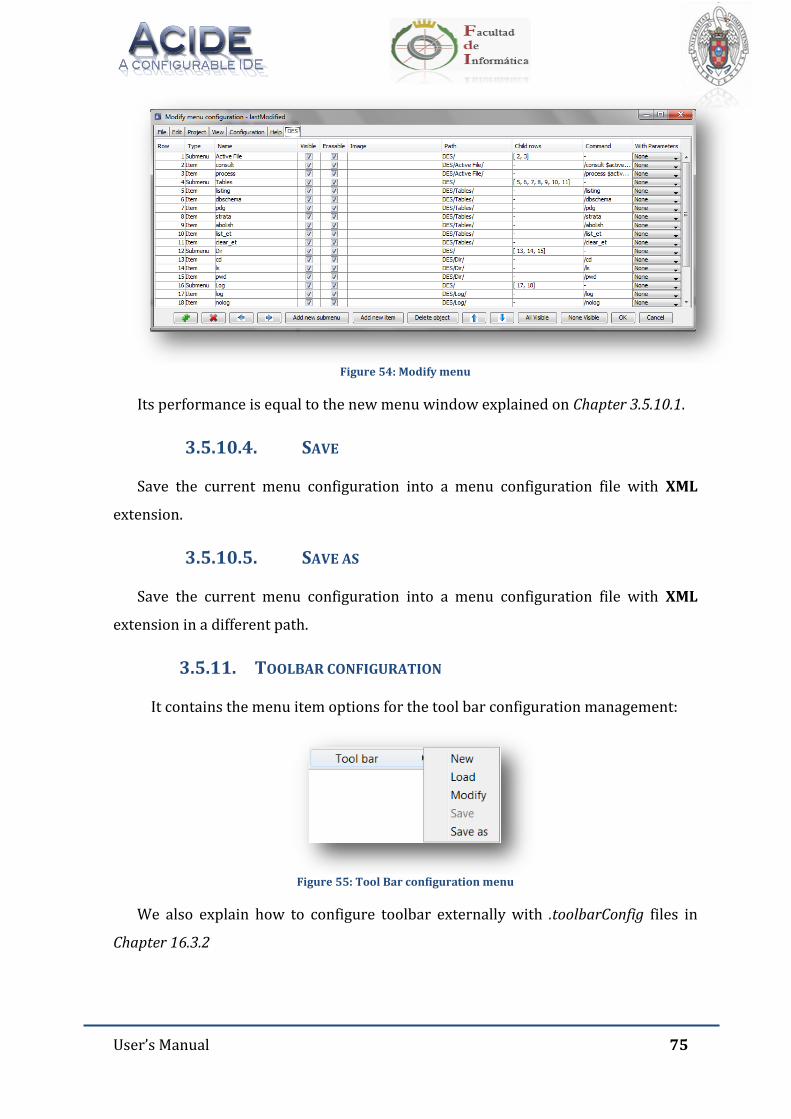
User’s Manual 75
Figure 54: Modify menu
Its performance is equal to the new menu window explained on Chapter 3.5.10.1.
3.5.10.4. SAVE
Save the current menu configuration into a menu configuration file with XML
extension.
3.5.10.5. SAVE AS
Save the current menu configuration into a menu configuration file with XML
extension in a different path.
3.5.11. TOOLBAR CONFIGURATION
It contains the menu item options for the tool bar configuration management:
Figure 55: Tool Bar configuration menu
We also explain how to configure toolbar externally with .toolbarConfig files in
Chapter 16.3.2
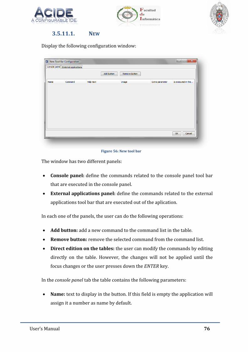
User’s Manual 76
3.5.11.1. NEW
Display the following configuration window:
Figure 56: New tool bar
The window has two different panels:
Console panel: define the commands related to the console panel tool bar
that are executed in the console panel.
External applications panel: define the commands related to the external
applications tool bar that are executed out of the aplication.
In each one of the panels, the user can do the following operations:
Add button: add a new command to the command list in the table.
Remove button: remove the selected command from the command list.
Direct edition on the tables: the user can modify the commands by editing
directly on the table. However, the changes will not be applied until the
focus changes or the user presses down the ENTER key.
In the console panel tab the table contains the following parameters:
Name: text to display in the button. If this field is empty the application will
assign it a number as name by default.

User’s Manual 77
Command: command itself. It admits the insertion of ACIDE – A
Configurable IDE special variables that are further detailed in the Chapter 0
of the present document.
Help text: hint text of the button.
Image: image for the button which can be selected by the option available
in the popupmenu of the column.
Extra parameter: show a combo box with the following options: NONE,
TEXT, FILE, DIRECTORY. Each one of the previous options will ask the user
for the selected type with different dialog windows.
Is executed in the OS console: indicate if the command is executed in the
Operative System console or in the loaded console in the console panel.
In the external applications panel tab the table contains the following
parameters:
Name: text to display in the button. If this field is empty the application will
assign it a number as name by default.
Executable path: executable path of the command to execute. It admits the
insertion of ACIDE – A Configurable IDE special variables that are further
detailed in Chapter 0 of the present document.
Help text: hint text of the button.
Image: image for the button which can be selected by the option available
in the popup menu of the column.
The tool bar configuration files have toolbarConfig extension.
3.5.11.2. LOAD
Load a tool bar configuration with toolbarConfig extension.
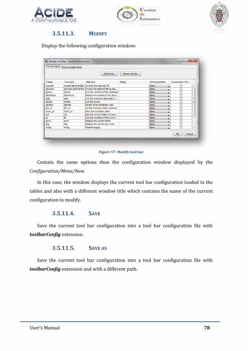
User’s Manual 78
3.5.11.3. MODIFY
Display the following configuration window:
Figure 57: Modify tool bar
Contain the same options than the configuration window displayed by the
Configuration/Menu/New.
In this case, the window displays the current tool bar configuration loaded in the
tables and also with a different window title which contains the name of the current
configuration to modify.
3.5.11.4. SAVE
Save the current tool bar configuration into a tool bar configuration file with
toolbarConfig extension.
3.5.11.5. SAVE AS
Save the current tool bar configuration into a tool bar configuration file with
toolbarConfig extension and with a different path.
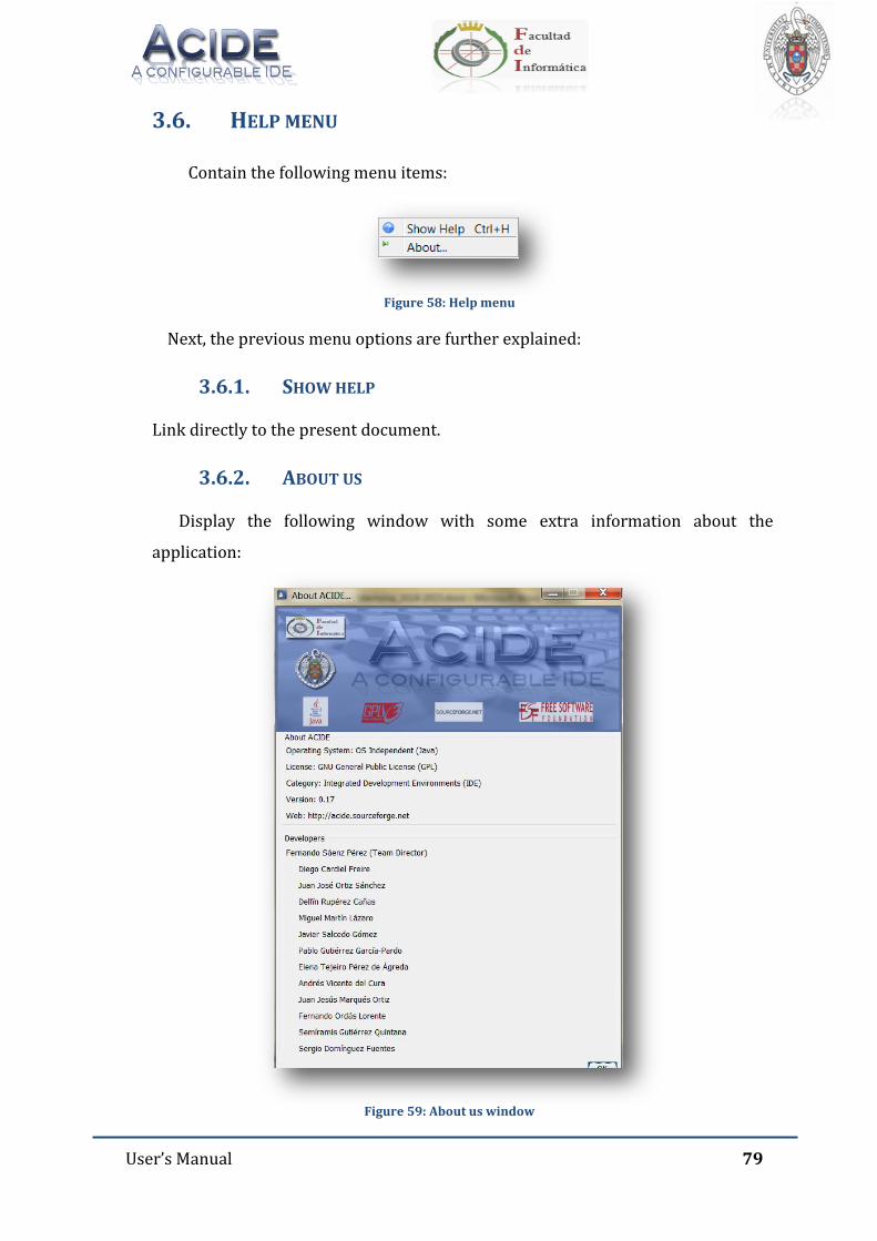
User’s Manual 79
3.6. HELP MENU
Contain the following menu items:
Figure 58: Help menu
Next, the previous menu options are further explained:
3.6.1. SHOW HELP
Link directly to the present document.
3.6.2. ABOUT US
Display the following window with some extra information about the
application:
Figure 59: About us window
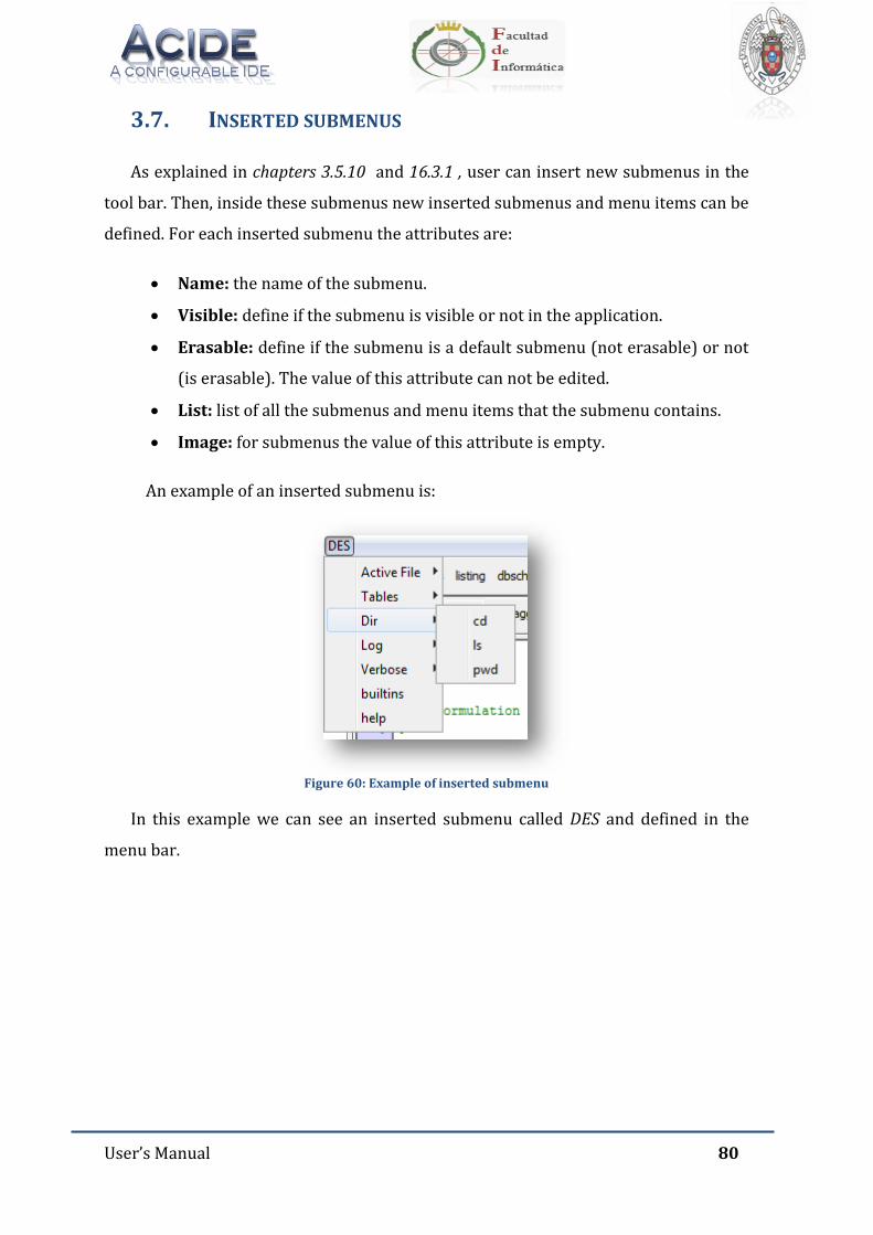
User’s Manual 80
3.7. INSERTED SUBMENUS
As explained in chapters 3.5.10 and 16.3.1 , user can insert new submenus in the
tool bar. Then, inside these submenus new inserted submenus and menu items can be
defined. For each inserted submenu the attributes are:
Name: the name of the submenu.
Visible: define if the submenu is visible or not in the application.
Erasable: define if the submenu is a default submenu (not erasable) or not
(is erasable). The value of this attribute can not be edited.
List: list of all the submenus and menu items that the submenu contains.
Image: for submenus the value of this attribute is empty.
An example of an inserted submenu is:
Figure 60: Example of inserted submenu
In this example we can see an inserted submenu called DES and defined in the
menu bar.
User’s Manual 81
3.8. INSERTED MENU ITEMS
As explained in chapters 3.5.10 and 16.3.1 , user can insert new menu items in the
tool bar. For each inserted menu item the attributes are:
Name: the name of the menu item.
Visible: define if the menu item is visible or not in the application.
Erasable: define if the menu item is a default menu item (not erasable) or
not (is erasable). The value of this attribute can not be edited.
Image: define the path of the image which is the icon of the menu item.
Command: define the command that is sent to console when this menu
item is clicked.
Parameter: define the type of parameter that the command of this menu
item needs: None, Text, File or Directory.
A example of inserted menu items can be seen in Chapter 3.7 of the present
document.
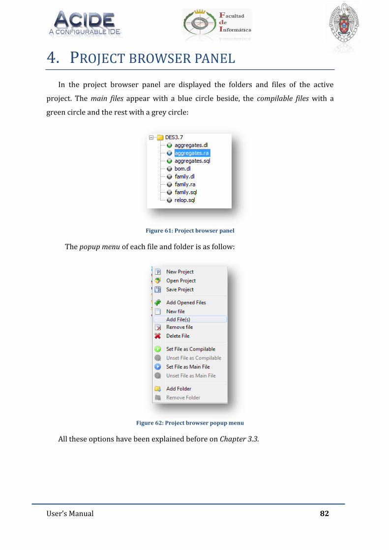
User’s Manual 82
4. PROJECT BROWSER PANEL
In the project browser panel are displayed the folders and files of the active
project. The main files appear with a blue circle beside, the compilable files with a
green circle and the rest with a grey circle:
Figure 61: Project browser panel
The popup menu of each file and folder is as follow:
Figure 62: Project browser popup menu
All these options have been explained before on Chapter 3.3.
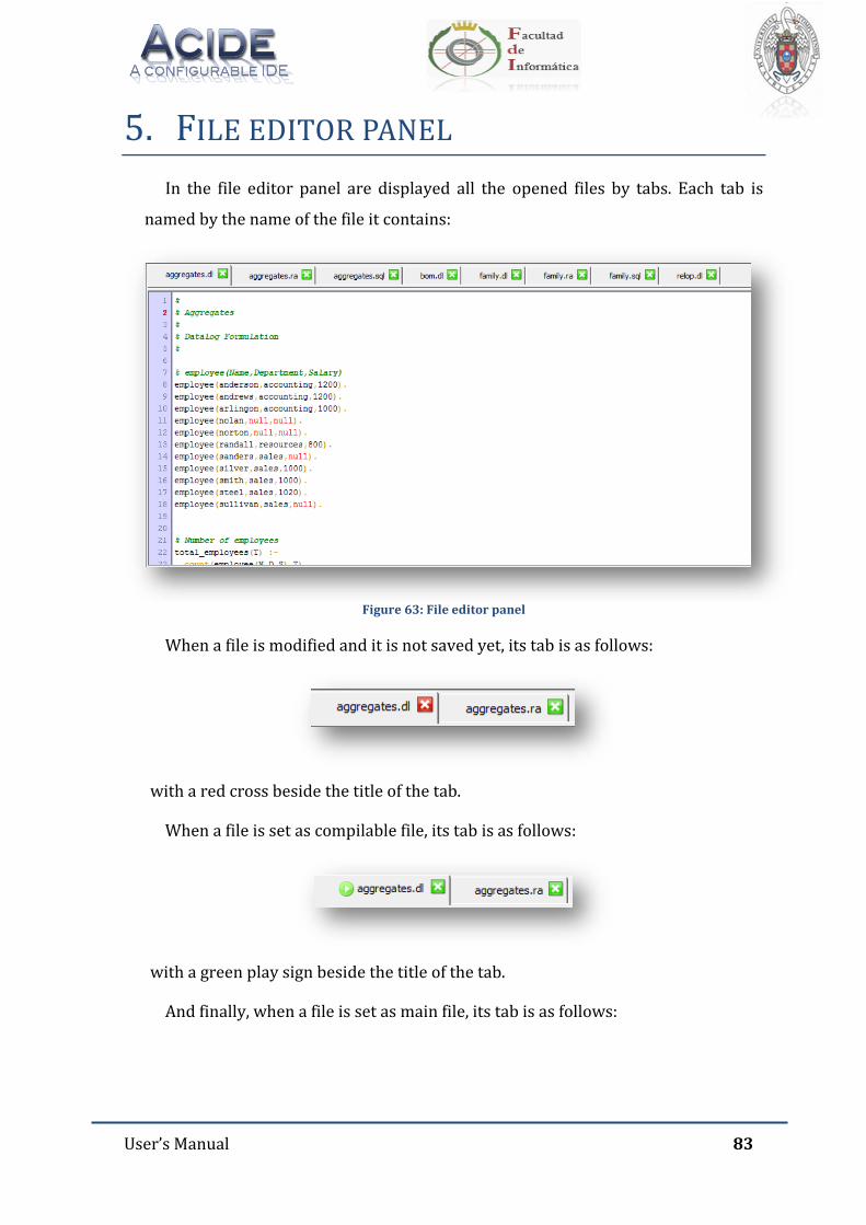
User’s Manual 83
5. FILE EDITOR PANEL
In the file editor panel are displayed all the opened files by tabs. Each tab is
named by the name of the file it contains:
Figure 63: File editor panel
When a file is modified and it is not saved yet, its tab is as follows:
with a red cross beside the title of the tab.
When a file is set as compilable file, its tab is as follows:
with a green play sign beside the title of the tab.
And finally, when a file is set as main file, its tab is as follows:
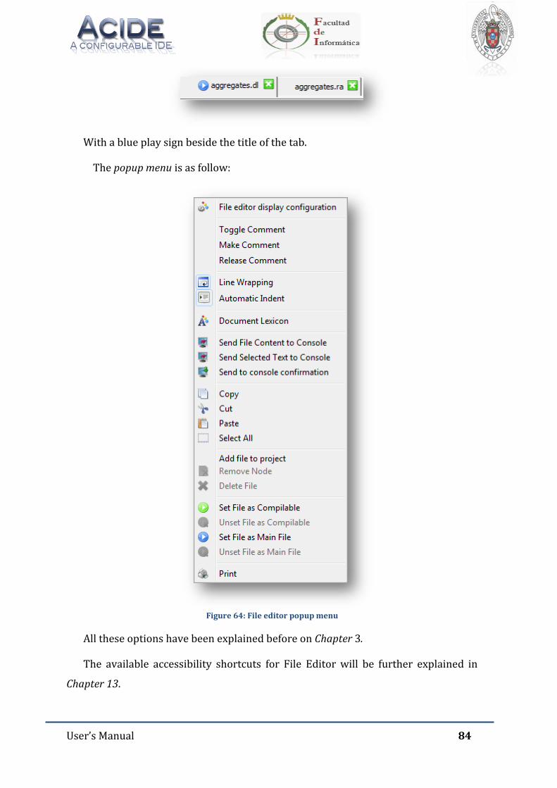
User’s Manual 84
With a blue play sign beside the title of the tab.
The popup menu is as follow:
Figure 64: File editor popup menu
All these options have been explained before on Chapter 3.
The available accessibility shortcuts for File Editor will be further explained in
Chapter 13.
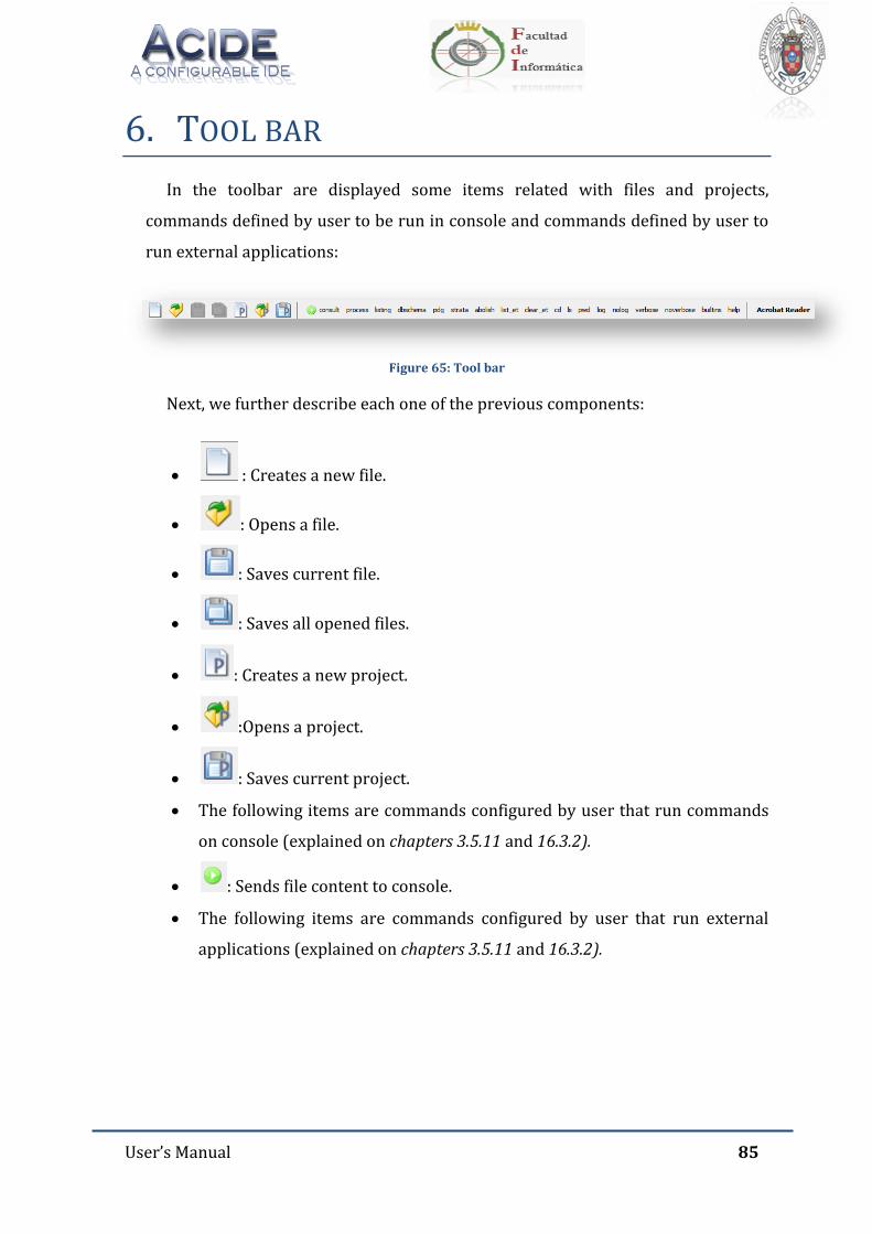
User’s Manual 85
6. TOOL BAR
In the toolbar are displayed some items related with files and projects,
commands defined by user to be run in console and commands defined by user to
run external applications:
Figure 65: Tool bar
Next, we further describe each one of the previous components:
: Creates a new file.
: Opens a file.
: Saves current file.
: Saves all opened files.
: Creates a new project.
:Opens a project.
: Saves current project.
The following items are commands configured by user that run commands
on console (explained on chapters 3.5.11 and 16.3.2).
: Sends file content to console.
The following items are commands configured by user that run external
applications (explained on chapters 3.5.11 and 16.3.2).
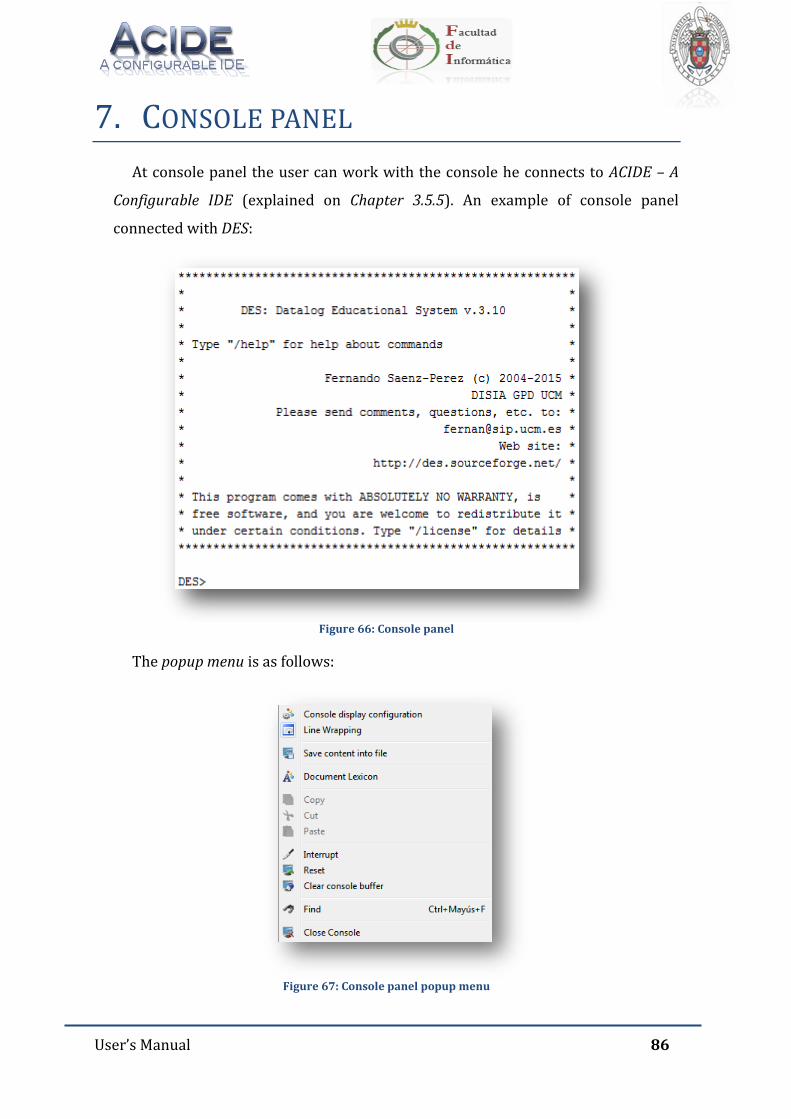
User’s Manual 86
7. CONSOLE PANEL
At console panel the user can work with the console he connects to ACIDE – A
Configurable IDE (explained on Chapter 3.5.5). An example of console panel
connected with DES:
Figure 66: Console panel
The popup menu is as follows:
Figure 67: Console panel popup menu

User’s Manual 87
All the options have been explained before in Chapter 3.
The user can send commands to the console in different ways. As explained
before, user can send the selected text or the content of a file to the sell. Also he can
configure the toolbar with buttons which send commands to console. A new
performance of this version is that user can configure the Menu Bar to build buttons
that send commands to console in the same way that the toolbar buttons. The default
buttons of ACIDE – A Configurable IDE send special commands that will be further
explained in Chapter 0.
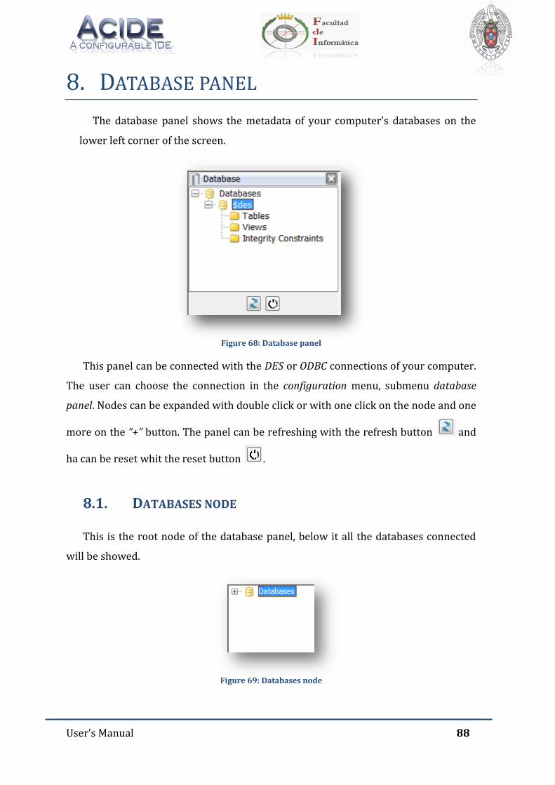
User’s Manual 88
8. DATABASE PANEL
The database panel shows the metadata of your computer’s databases on the
lower left corner of the screen.
Figure 68: Database panel
This panel can be connected with the DES or ODBC connections of your computer.
The user can choose the connection in the configuration menu, submenu database
panel. Nodes can be expanded with double click or with one click on the node and one
more on the “+” button. The panel can be refreshing with the refresh button and
ha can be reset whit the reset button .
8.1. DATABASES NODE
This is the root node of the database panel, below it all the databases connected
will be showed.
Figure 69: Databases node
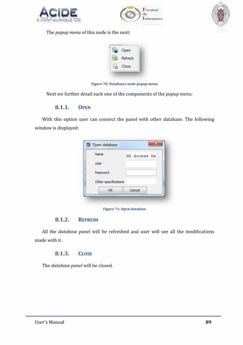
User’s Manual 89
The popup menu of this node is the next:
Figure 70: Databases node popup menu
Next we further detail each one of the components of the popup menu:
8.1.1. OPEN
With this option user can connect the panel with other database. The following
window is displayed:
Figure 71: Open database
8.1.2. REFRESH
All the database panel will be refreshed and user will see all the modifications
made with it.
8.1.3. CLOSE
The database panel will be closed.
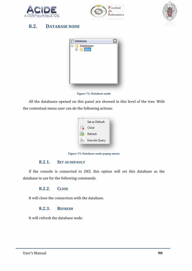
User’s Manual 90
8.2. DATABASE NODE
Figure 72: Database node
All the databases opened on this panel are showed in this level of the tree. With
the contextual menu user can do the following actions:
Figure 73: Database node popup menu
8.2.1. SET AS DEFAULT
If the console is connected to DES, this option will set this database as the
database in use for the following commands.
8.2.2. CLOSE
It will close the connection with the database.
8.2.3. REFRESH
It will refresh the database node.
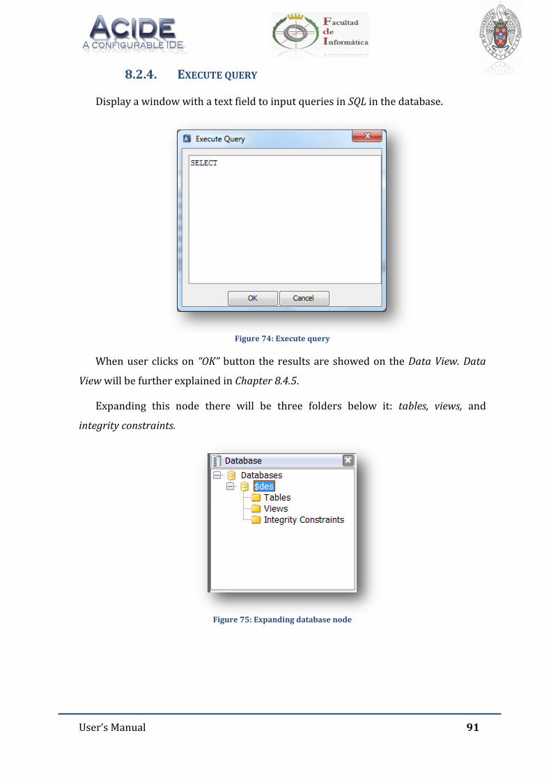
User’s Manual 91
8.2.4. EXECUTE QUERY
Display a window with a text field to input queries in SQL in the database.
Figure 74: Execute query
When user clicks on “OK” button the results are showed on the Data View. Data
View will be further explained in Chapter 8.4.5.
Expanding this node there will be three folders below it: tables, views, and
integrity constraints.
Figure 75: Expanding database node
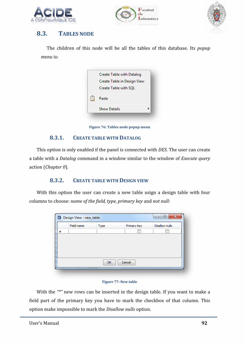
User’s Manual 92
8.3. TABLES NODE
The children of this node will be all the tables of this database. Its popup
menu is:
Figure 76: Tables node popup menu
8.3.1. CREATE TABLE WITH DATALOG
This option is only enabled if the panel is connected with DES. The user can create
a table with a Datalog command in a window similar to the window of Execute query
action (Chapter 0).
8.3.2. CREATE TABLE WITH DESIGN VIEW
With this option the user can create a new table usign a design table with four
columns to choose: name of the field, type, primary key and not null:
Figure 77: New table
With the “*” new rows can be inserted in the design table. If you want to make a
field part of the primary key you have to mark the checkbox of that column. This
option make impossible to mark the Disallow nulls option.
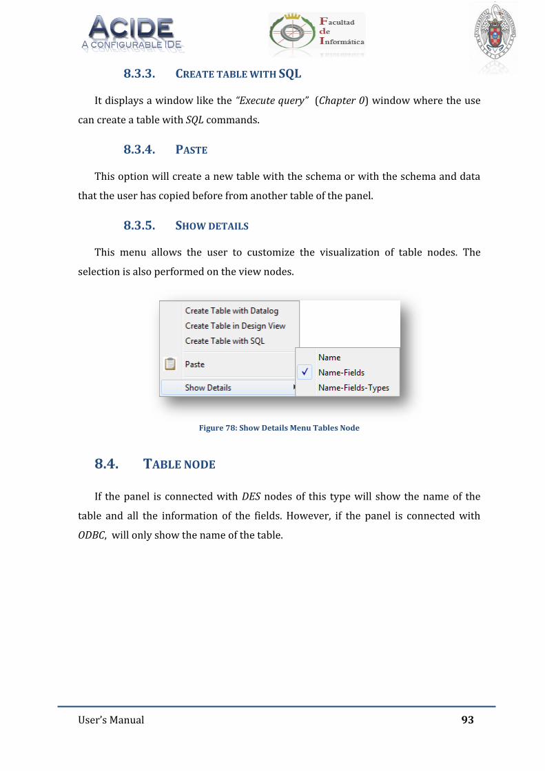
User’s Manual 93
8.3.3. CREATE TABLE WITH SQL
It displays a window like the “Execute query” (Chapter 0) window where the use
can create a table with SQL commands.
8.3.4. PASTE
This option will create a new table with the schema or with the schema and data
that the user has copied before from another table of the panel.
8.3.5. SHOW DETAILS
This menu allows the user to customize the visualization of table nodes. The
selection is also performed on the view nodes.
Figure 78: Show Details Menu Tables Node
8.4. TABLE NODE
If the panel is connected with DES nodes of this type will show the name of the
table and all the information of the fields. However, if the panel is connected with
ODBC, will only show the name of the table.
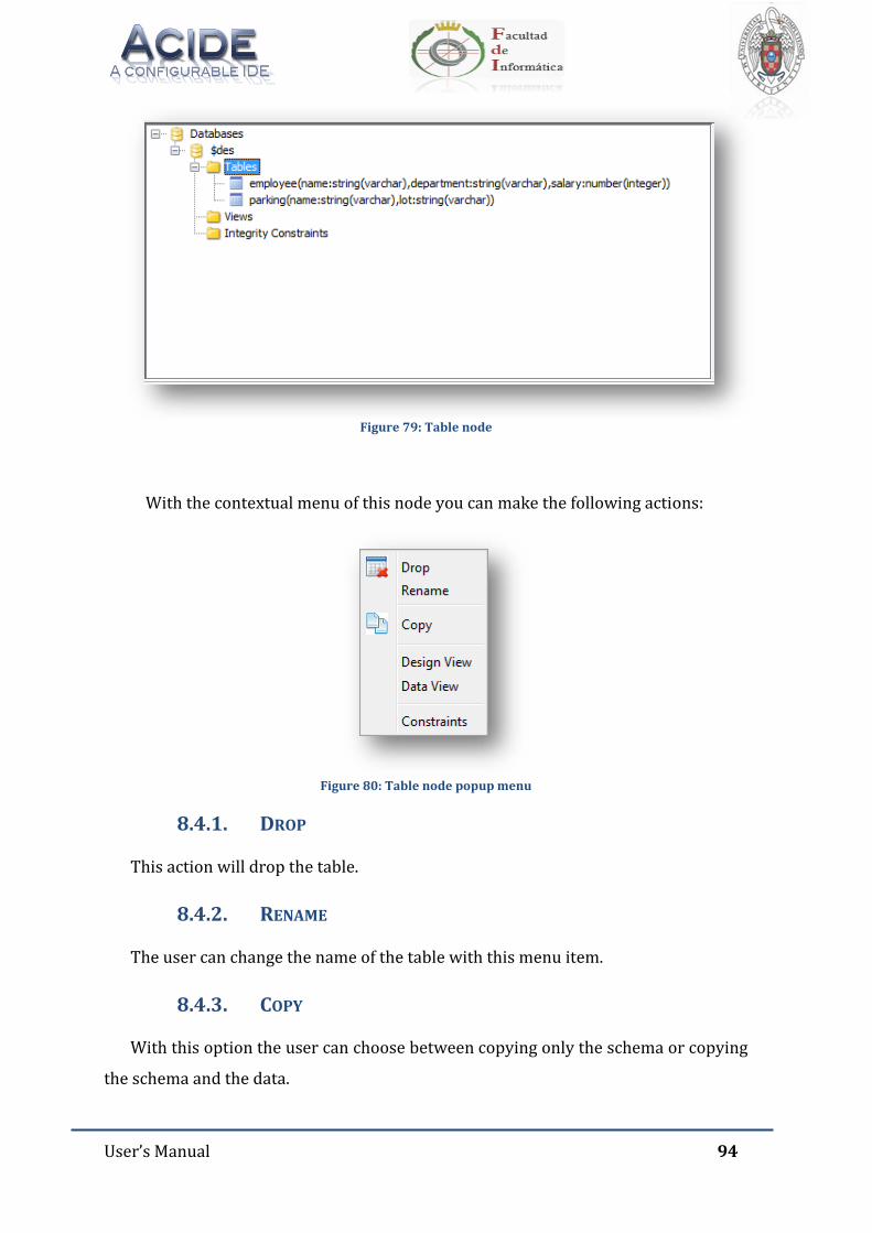
User’s Manual 94
Figure 79: Table node
With the contextual menu of this node you can make the following actions:
Figure 80: Table node popup menu
8.4.1. DROP
This action will drop the table.
8.4.2. RENAME
The user can change the name of the table with this menu item.
8.4.3. COPY
With this option the user can choose between copying only the schema or copying
the schema and the data.
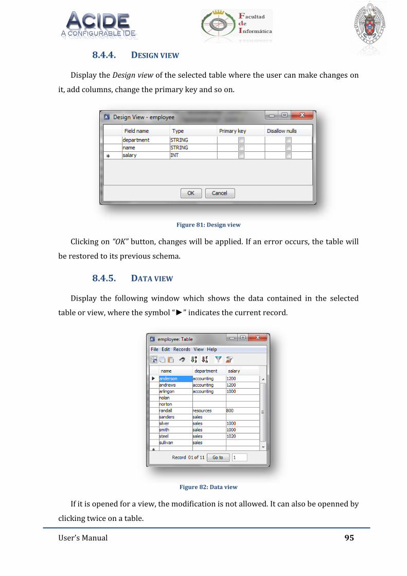
User’s Manual 95
8.4.4. DESIGN VIEW
Display the Design view of the selected table where the user can make changes on
it, add columns, change the primary key and so on.
Figure 81: Design view
Clicking on “OK” button, changes will be applied. If an error occurs, the table will
be restored to its previous schema.
8.4.5. DATA VIEW
Display the following window which shows the data contained in the selected
table or view, where the symbol “►” indicates the current record.
Figure 82: Data view
If it is opened for a view, the modification is not allowed. It can also be openned by
clicking twice on a table.
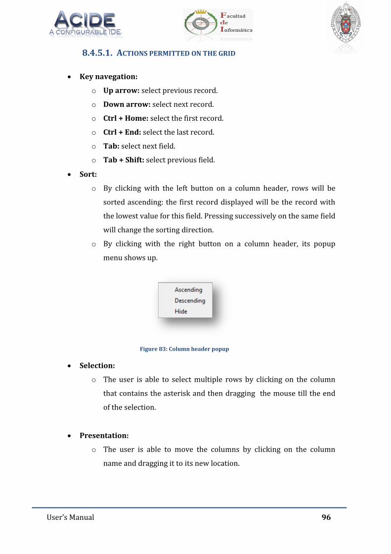
User’s Manual 96
8.4.5.1. ACTIONS PERMITTED ON THE GRID
Key navegation:
o Up arrow: select previous record.
o Down arrow: select next record.
o Ctrl + Home: select the first record.
o Ctrl + End: select the last record.
o Tab: select next field.
o Tab + Shift: select previous field.
Sort:
o By clicking with the left button on a column header, rows will be
sorted ascending: the first record displayed will be the record with
the lowest value for this field. Pressing successively on the same field
will change the sorting direction.
o By clicking with the right button on a column header, its popup
menu shows up.
Figure 83: Column header popup
Selection:
o The user is able to select multiple rows by clicking on the column
that contains the asterisk and then dragging the mouse till the end
of the selection.
Presentation:
o The user is able to move the columns by clicking on the column
name and dragging it to its new location.
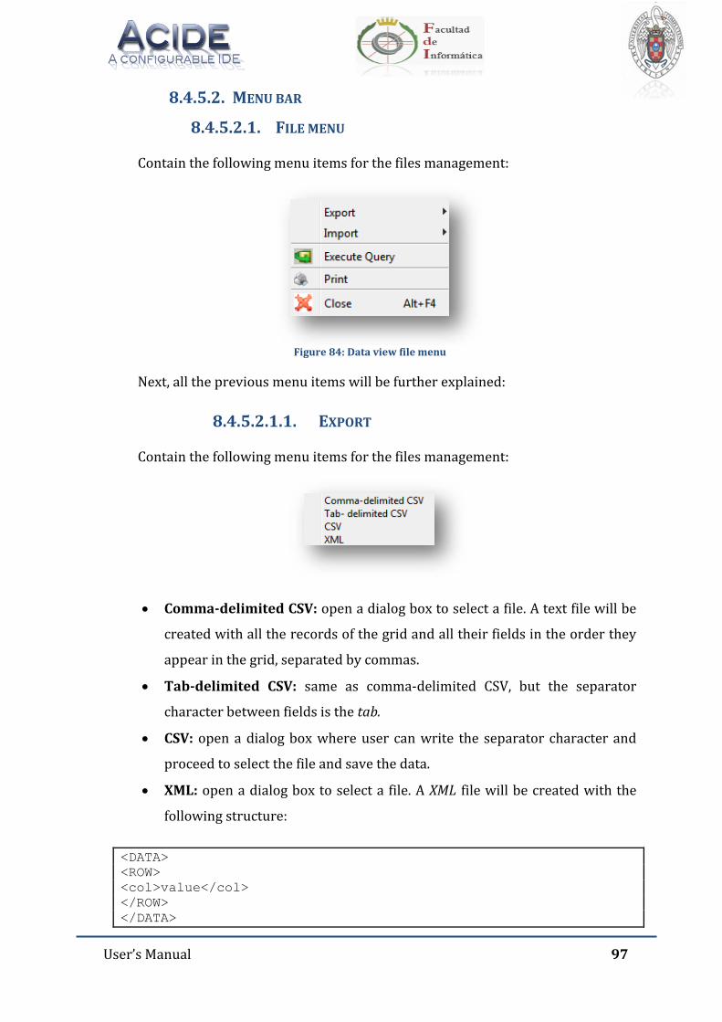
User’s Manual 97
8.4.5.2. MENU BAR
8.4.5.2.1. FILE MENU
Contain the following menu items for the files management:
Figure 84: Data view file menu
Next, all the previous menu items will be further explained:
8.4.5.2.1.1. EXPORT
Contain the following menu items for the files management:
Comma-delimited CSV: open a dialog box to select a file. A text file will be
created with all the records of the grid and all their fields in the order they
appear in the grid, separated by commas.
Tab-delimited CSV: same as comma-delimited CSV, but the separator
character between fields is the tab.
CSV: open a dialog box where user can write the separator character and
proceed to select the file and save the data.
XML: open a dialog box to select a file. A XML file will be created with the
following structure:
<DATA>
<ROW>
<col>value</col>
</ROW>
</DATA>
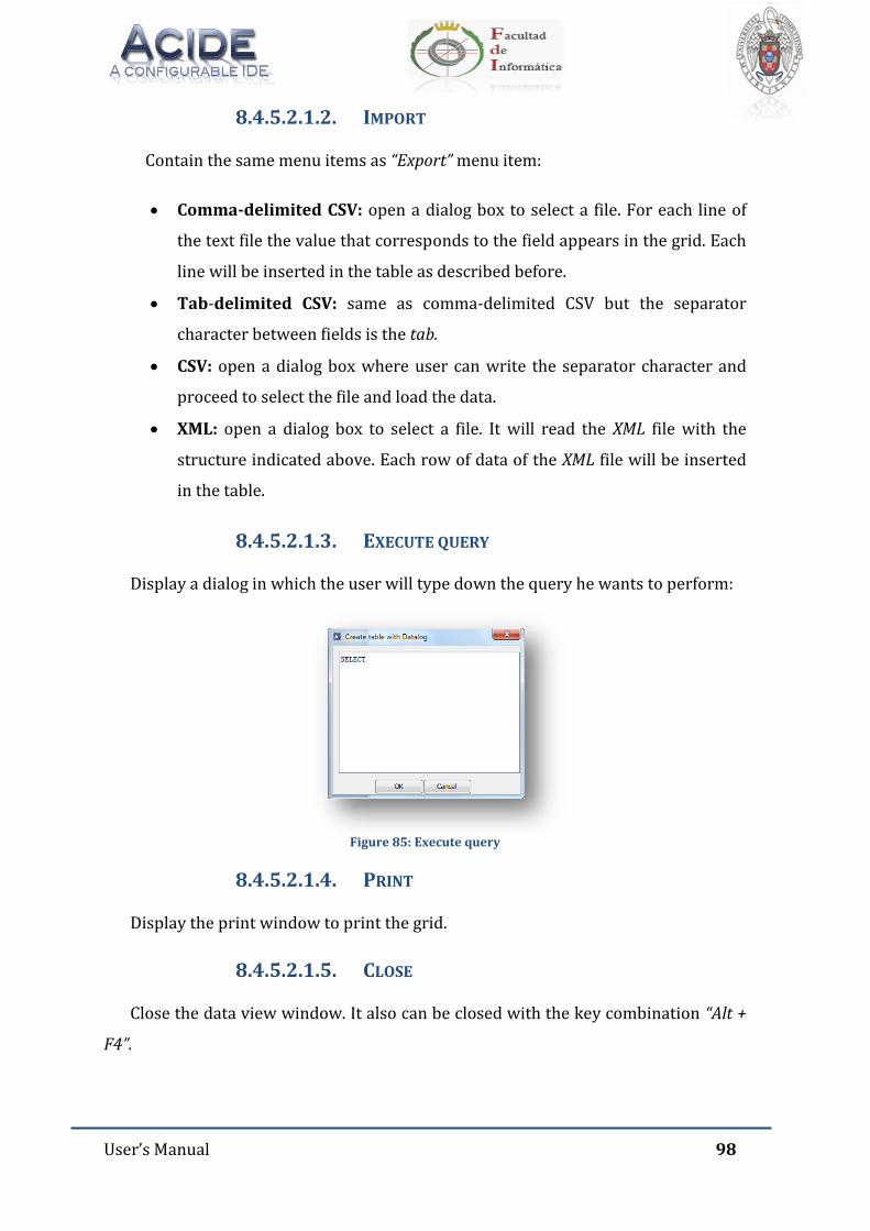
User’s Manual 98
8.4.5.2.1.2. IMPORT
Contain the same menu items as “Export” menu item:
Comma-delimited CSV: open a dialog box to select a file. For each line of
the text file the value that corresponds to the field appears in the grid. Each
line will be inserted in the table as described before.
Tab-delimited CSV: same as comma-delimited CSV but the separator
character between fields is the tab.
CSV: open a dialog box where user can write the separator character and
proceed to select the file and load the data.
XML: open a dialog box to select a file. It will read the XML file with the
structure indicated above. Each row of data of the XML file will be inserted
in the table.
8.4.5.2.1.3. EXECUTE QUERY
Display a dialog in which the user will type down the query he wants to perform:
Figure 85: Execute query
8.4.5.2.1.4. PRINT
Display the print window to print the grid.
8.4.5.2.1.5. CLOSE
Close the data view window. It also can be closed with the key combination “Alt +
F4”.

User’s Manual 99
8.4.5.2.2. EDIT MENU
Contain the following menu items for the common grid editor management:
Figure 86: Data view edit menu
8.4.5.2.2.1. UNDO
Undo the updates in the grid. It also can be done with the key combination “Ctrl +
Z”.
8.4.5.2.2.2. REDO
Redo the updates in the grid. It also can be done with the key combination “Ctrl +
Y”.
8.4.5.2.2.3. COPY
Copy the selected text from the grid and put it into the System clipboard. It also
can be done with the key combination “Ctrl+ C” or with the icon of the icon bar.
8.4.5.2.2.4. PASTE
Paste the text stored in the System clipboard in the current position of the cursor
in the grid. It also can be done with the key combination “Ctrl + V” or with the icon
of the icon bar.
8.4.5.2.2.5. CUT
Cut the selected text active field from the grid and put it into the System clipboard.
It also can be done with the key combination “Ctrl + X” or with the icon of the icon
bar.
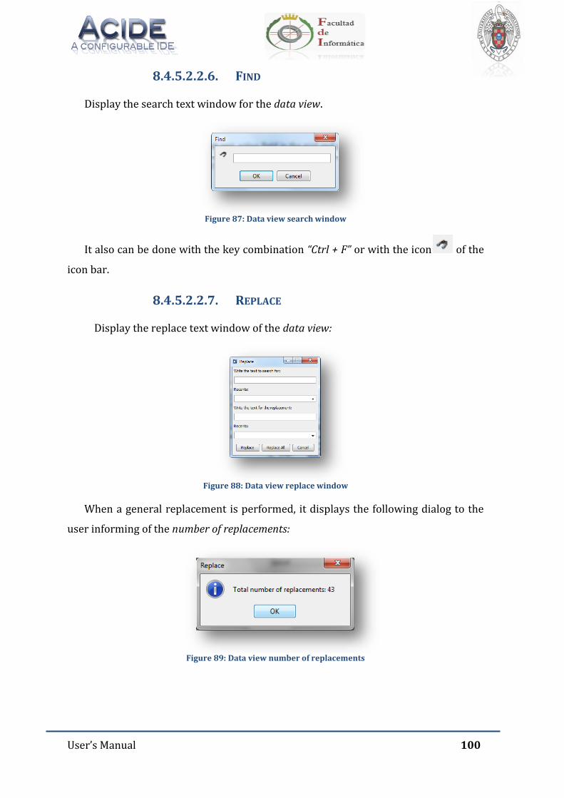
User’s Manual 100
8.4.5.2.2.6. FIND
Display the search text window for the data view.
Figure 87: Data view search window
It also can be done with the key combination “Ctrl + F” or with the icon of the
icon bar.
8.4.5.2.2.7. REPLACE
Display the replace text window of the data view:
Figure 88: Data view replace window
When a general replacement is performed, it displays the following dialog to the
user informing of the number of replacements:
Figure 89: Data view number of replacements
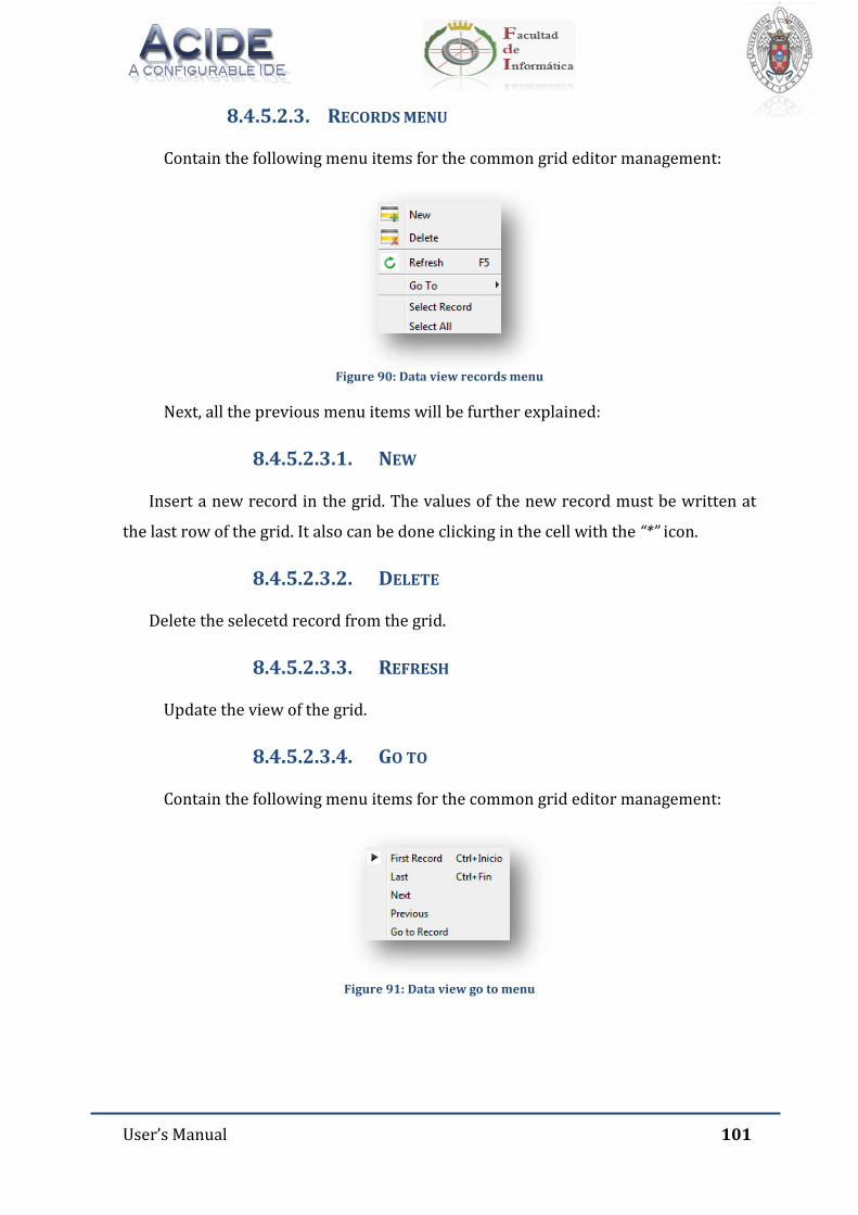
User’s Manual 101
8.4.5.2.3. RECORDS MENU
Contain the following menu items for the common grid editor management:
Figure 90: Data view records menu
Next, all the previous menu items will be further explained:
8.4.5.2.3.1. NEW
Insert a new record in the grid. The values of the new record must be written at
the last row of the grid. It also can be done clicking in the cell with the “*” icon.
8.4.5.2.3.2. DELETE
Delete the selecetd record from the grid.
8.4.5.2.3.3. REFRESH
Update the view of the grid.
8.4.5.2.3.4. GO TO
Contain the following menu items for the common grid editor management:
Figure 91: Data view go to menu
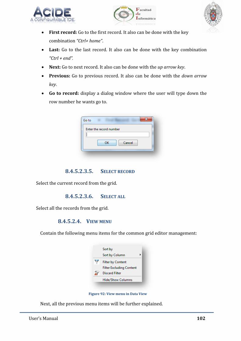
User’s Manual 102
First record: Go to the first record. It also can be done with the key
combination “Ctrl+ home”.
Last: Go to the last record. It also can be done with the key combination
“Ctrl + end”.
Next: Go to next record. It also can be done with the up arrow key.
Previous: Go to previous record. It also can be done with the down arrow
key.
Go to record: display a dialog window where the user will type down the
row number he wants go to.
8.4.5.2.3.5. SELECT RECORD
Select the current record from the grid.
8.4.5.2.3.6. SELECT ALL
Select all the records from the grid.
8.4.5.2.4. VIEW MENU
Contain the following menu items for the common grid editor management:
Figure 92: View menu in Data View
Next, all the previous menu items will be further explained.
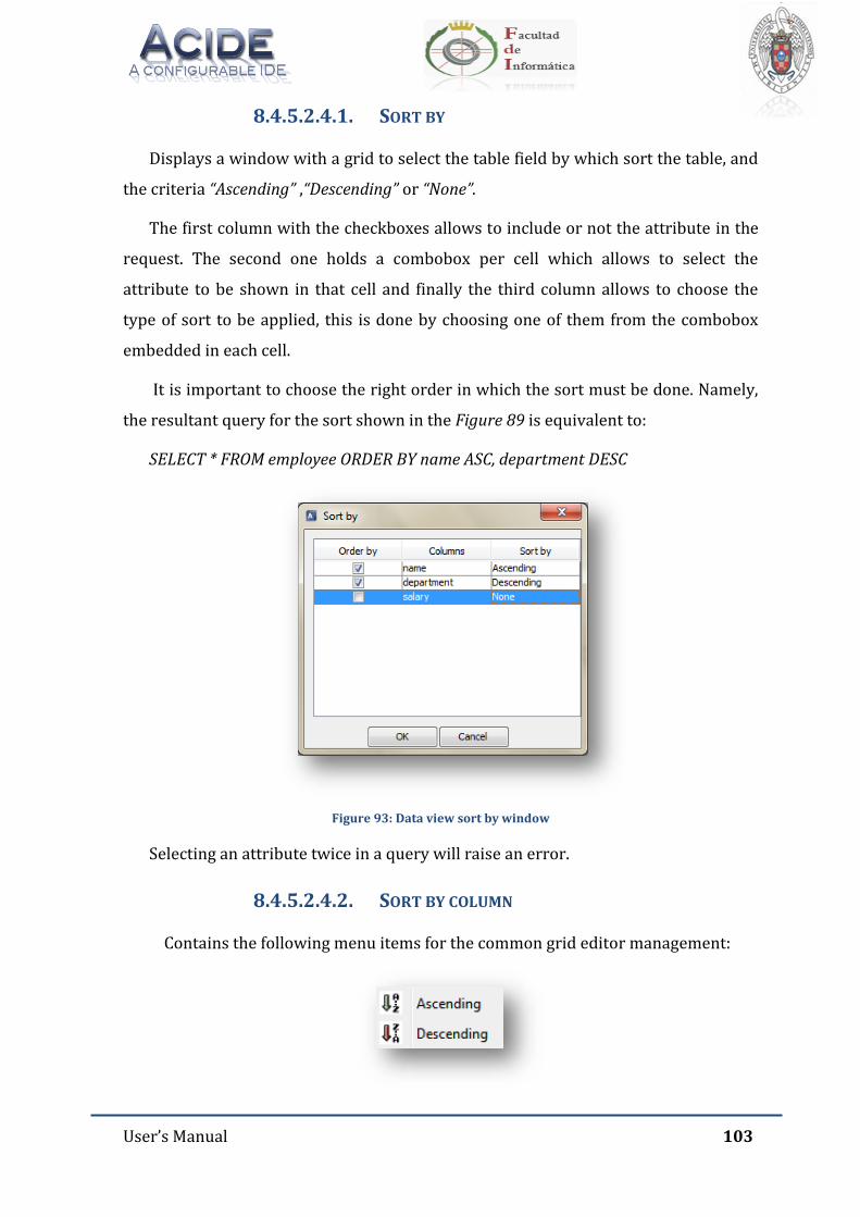
User’s Manual 103
8.4.5.2.4.1. SORT BY
Displays a window with a grid to select the table field by which sort the table, and
the criteria “Ascending” ,“Descending” or “None”.
The first column with the checkboxes allows to include or not the attribute in the
request. The second one holds a combobox per cell which allows to select the
attribute to be shown in that cell and finally the third column allows to choose the
type of sort to be applied, this is done by choosing one of them from the combobox
embedded in each cell.
It is important to choose the right order in which the sort must be done. Namely,
the resultant query for the sort shown in the Figure 89 is equivalent to:
SELECT * FROM employee ORDER BY name ASC, department DESC
Figure 93: Data view sort by window
Selecting an attribute twice in a query will raise an error.
8.4.5.2.4.2. SORT BY COLUMN
Contains the following menu items for the common grid editor management:
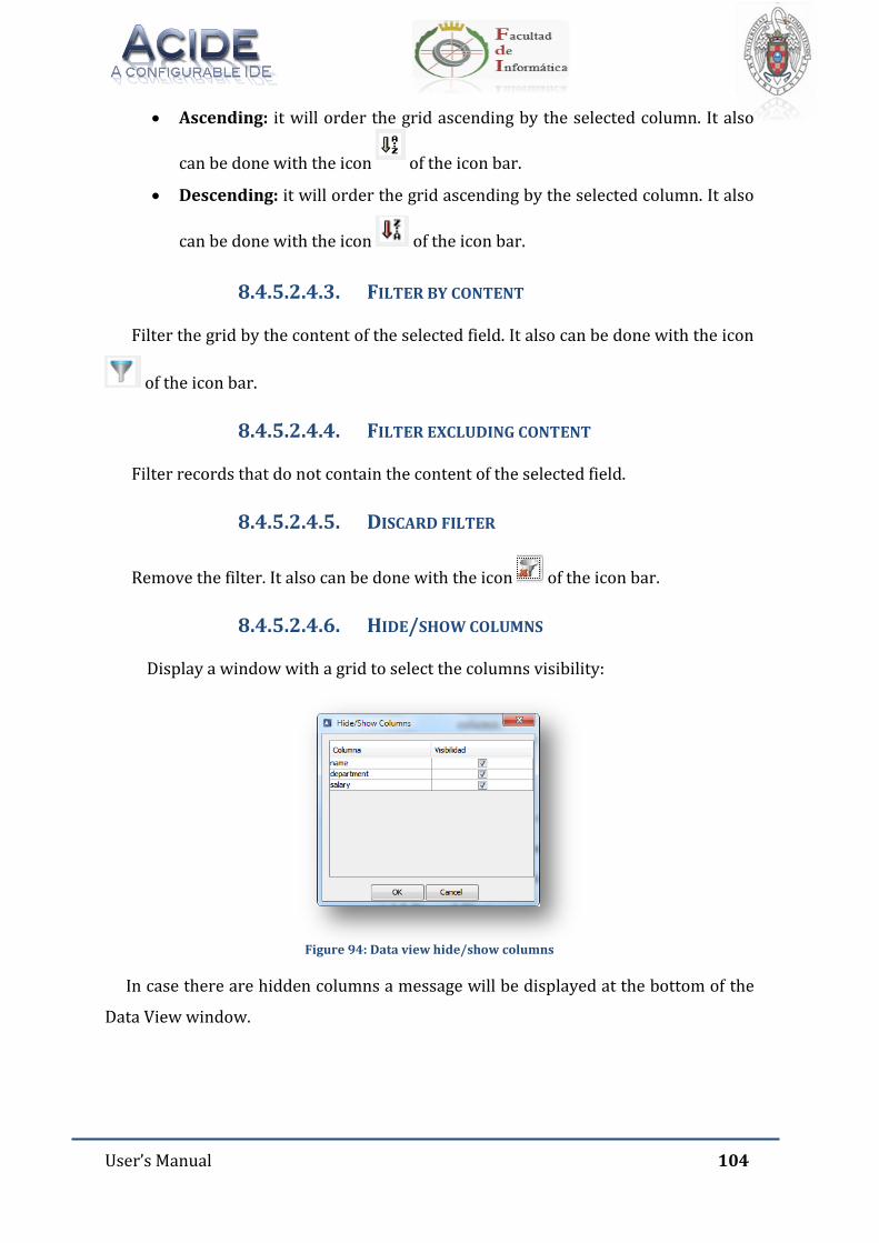
User’s Manual 104
Ascending: it will order the grid ascending by the selected column. It also
can be done with the icon of the icon bar.
Descending: it will order the grid ascending by the selected column. It also
can be done with the icon of the icon bar.
8.4.5.2.4.3. FILTER BY CONTENT
Filter the grid by the content of the selected field. It also can be done with the icon
of the icon bar.
8.4.5.2.4.4. FILTER EXCLUDING CONTENT
Filter records that do not contain the content of the selected field.
8.4.5.2.4.5. DISCARD FILTER
Remove the filter. It also can be done with the icon of the icon bar.
8.4.5.2.4.6. HIDE/SHOW COLUMNS
Display a window with a grid to select the columns visibility:
Figure 94: Data view hide/show columns
In case there are hidden columns a message will be displayed at the bottom of the
Data View window.

User’s Manual 105
8.4.5.2.5. HELP MENU
Contain the following menu items:
Figure 95: Data view help menu
Next, the previous menu options are further explained
8.4.5.2.5.1. SHOW HELP
Link directly to the user’s manual of DES-ACIDE.
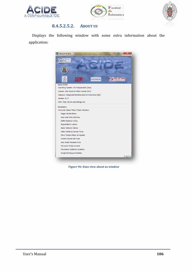
User’s Manual 106
8.4.5.2.5.2. ABOUT US
Displays the following window with some extra information about the
application:
Figure 96: Data view about us window
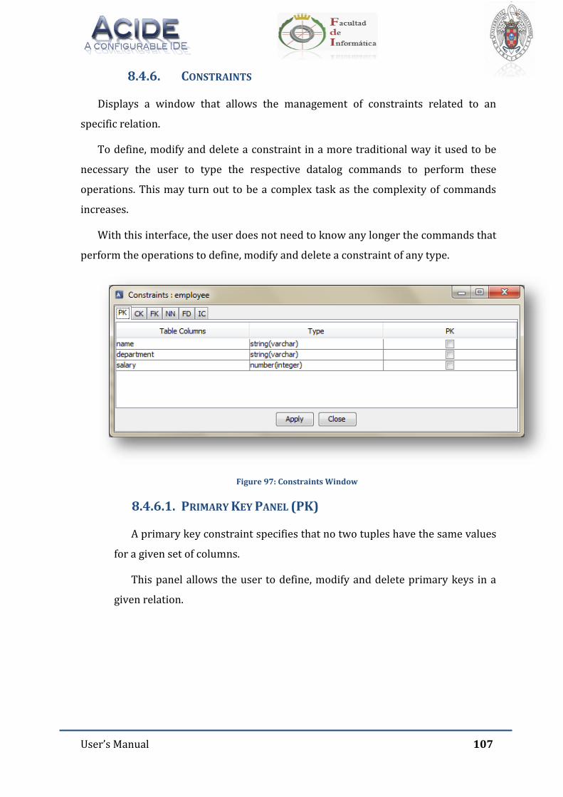
User’s Manual 107
8.4.6. CONSTRAINTS
Displays a window that allows the management of constraints related to an
specific relation.
To define, modify and delete a constraint in a more traditional way it used to be
necessary the user to type the respective datalog commands to perform these
operations. This may turn out to be a complex task as the complexity of commands
increases.
With this interface, the user does not need to know any longer the commands that
perform the operations to define, modify and delete a constraint of any type.
Figure 97: Constraints Window
8.4.6.1. PRIMARY KEY PANEL (PK)
A primary key constraint specifies that no two tuples have the same values
for a given set of columns.
This panel allows the user to define, modify and delete primary keys in a
given relation.
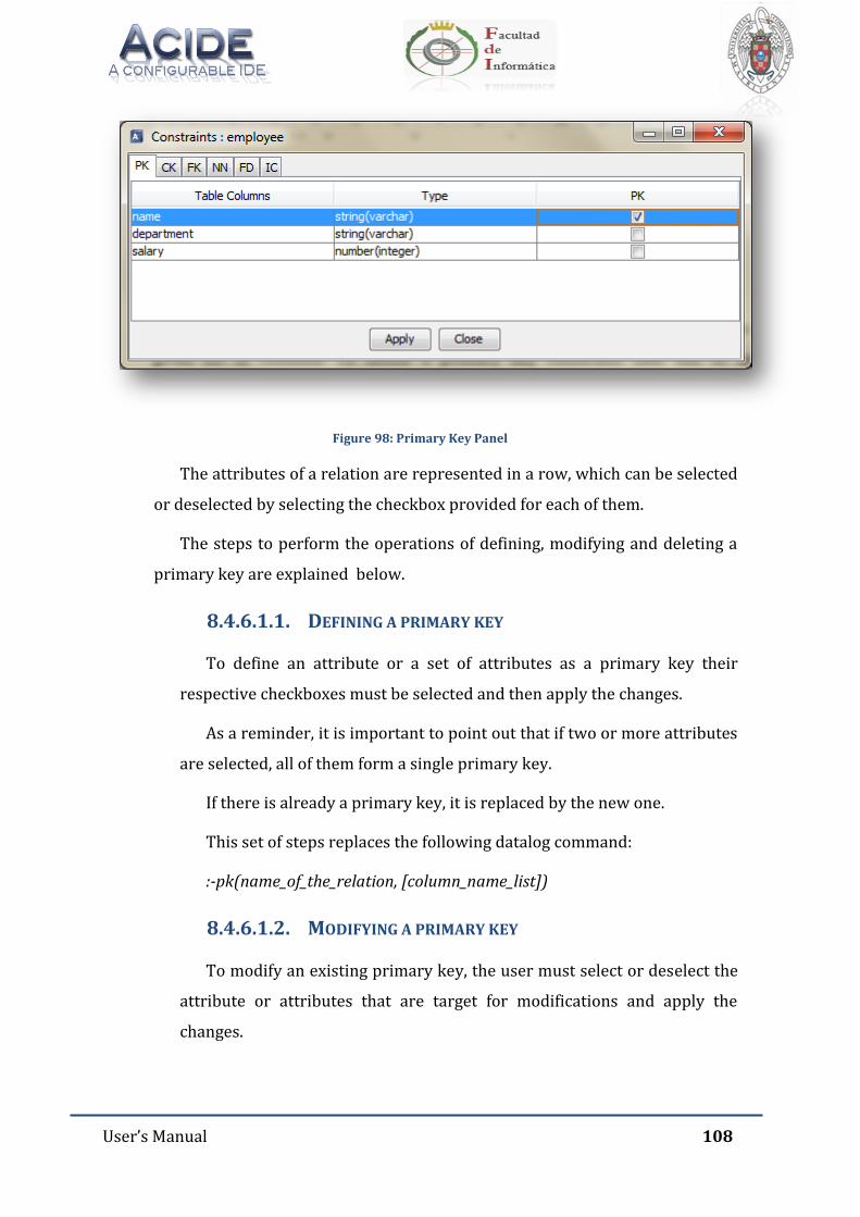
User’s Manual 108
Figure 98: Primary Key Panel
The attributes of a relation are represented in a row, which can be selected
or deselected by selecting the checkbox provided for each of them.
The steps to perform the operations of defining, modifying and deleting a
primary key are explained below.
8.4.6.1.1. DEFINING A PRIMARY KEY
To define an attribute or a set of attributes as a primary key their
respective checkboxes must be selected and then apply the changes.
As a reminder, it is important to point out that if two or more attributes
are selected, all of them form a single primary key.
If there is already a primary key, it is replaced by the new one.
This set of steps replaces the following datalog command:
:-pk(name_of_the_relation, [column_name_list])
8.4.6.1.2. MODIFYING A PRIMARY KEY
To modify an existing primary key, the user must select or deselect the
attribute or attributes that are target for modifications and apply the
changes.
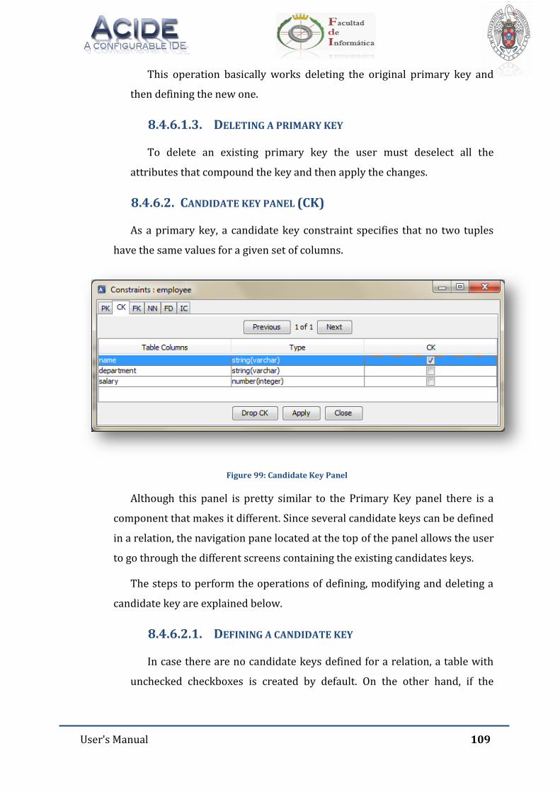
User’s Manual 109
This operation basically works deleting the original primary key and
then defining the new one.
8.4.6.1.3. DELETING A PRIMARY KEY
To delete an existing primary key the user must deselect all the
attributes that compound the key and then apply the changes.
8.4.6.2. CANDIDATE KEY PANEL (CK)
As a primary key, a candidate key constraint specifies that no two tuples
have the same values for a given set of columns.
Figure 99: Candidate Key Panel
Although this panel is pretty similar to the Primary Key panel there is a
component that makes it different. Since several candidate keys can be defined
in a relation, the navigation pane located at the top of the panel allows the user
to go through the different screens containing the existing candidates keys.
The steps to perform the operations of defining, modifying and deleting a
candidate key are explained below.
8.4.6.2.1. DEFINING A CANDIDATE KEY
In case there are no candidate keys defined for a relation, a table with
unchecked checkboxes is created by default. On the other hand, if the
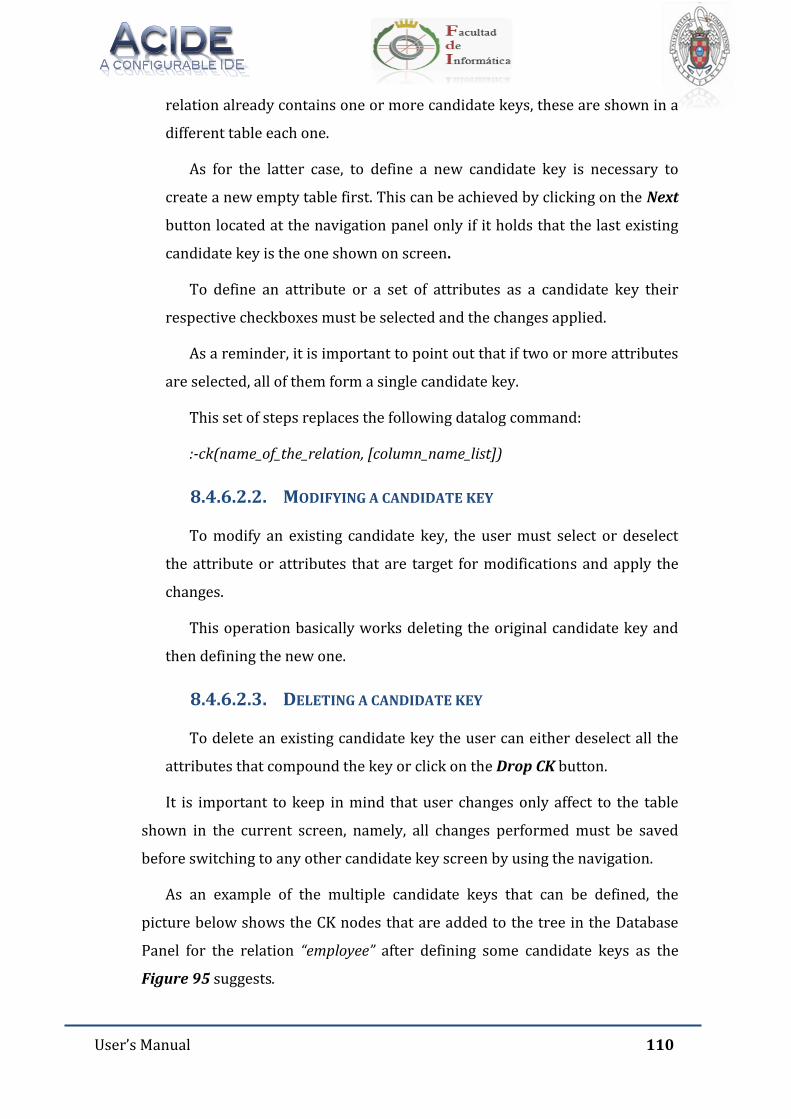
User’s Manual 110
relation already contains one or more candidate keys, these are shown in a
different table each one.
As for the latter case, to define a new candidate key is necessary to
create a new empty table first. This can be achieved by clicking on the Next
button located at the navigation panel only if it holds that the last existing
candidate key is the one shown on screen.
To define an attribute or a set of attributes as a candidate key their
respective checkboxes must be selected and the changes applied.
As a reminder, it is important to point out that if two or more attributes
are selected, all of them form a single candidate key.
This set of steps replaces the following datalog command:
:-ck(name_of_the_relation, [column_name_list])
8.4.6.2.2. MODIFYING A CANDIDATE KEY
To modify an existing candidate key, the user must select or deselect
the attribute or attributes that are target for modifications and apply the
changes.
This operation basically works deleting the original candidate key and
then defining the new one.
8.4.6.2.3. DELETING A CANDIDATE KEY
To delete an existing candidate key the user can either deselect all the
attributes that compound the key or click on the Drop CK button.
It is important to keep in mind that user changes only affect to the table
shown in the current screen, namely, all changes performed must be saved
before switching to any other candidate key screen by using the navigation.
As an example of the multiple candidate keys that can be defined, the
picture below shows the CK nodes that are added to the tree in the Database
Panel for the relation “employee” after defining some candidate keys as the
Figure 95 suggests.
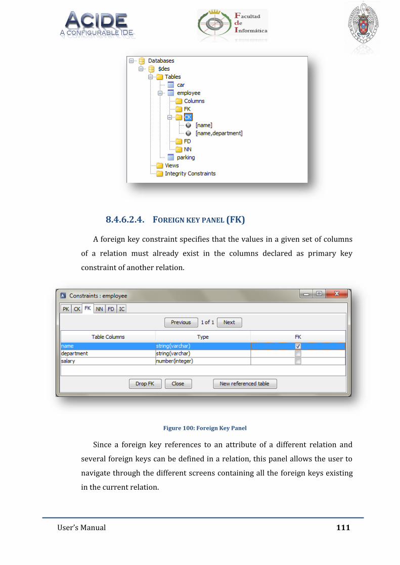
User’s Manual 111
8.4.6.2.4. FOREIGN KEY PANEL (FK)
A foreign key constraint specifies that the values in a given set of columns
of a relation must already exist in the columns declared as primary key
constraint of another relation.
Figure 100: Foreign Key Panel
Since a foreign key references to an attribute of a different relation and
several foreign keys can be defined in a relation, this panel allows the user to
navigate through the different screens containing all the foreign keys existing
in the current relation.
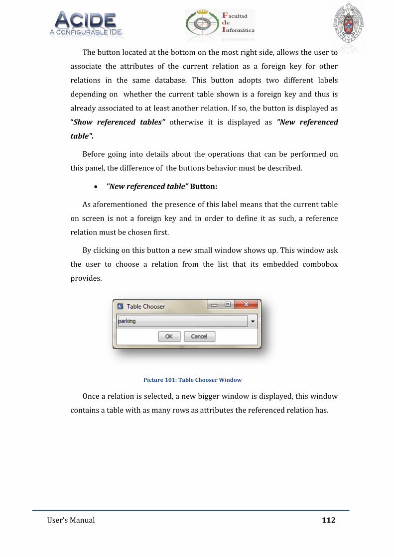
User’s Manual 112
The button located at the bottom on the most right side, allows the user to
associate the attributes of the current relation as a foreign key for other
relations in the same database. This button adopts two different labels
depending on whether the current table shown is a foreign key and thus is
already associated to at least another relation. If so, the button is displayed as
“Show referenced tables” otherwise it is displayed as "New referenced
table".
Before going into details about the operations that can be performed on
this panel, the difference of the buttons behavior must be described.
"New referenced table" Button:
As aforementioned the presence of this label means that the current table
on screen is not a foreign key and in order to define it as such, a reference
relation must be chosen first.
By clicking on this button a new small window shows up. This window ask
the user to choose a relation from the list that its embedded combobox
provides.
Picture 101: Table Chooser Window
Once a relation is selected, a new bigger window is displayed, this window
contains a table with as many rows as attributes the referenced relation has.
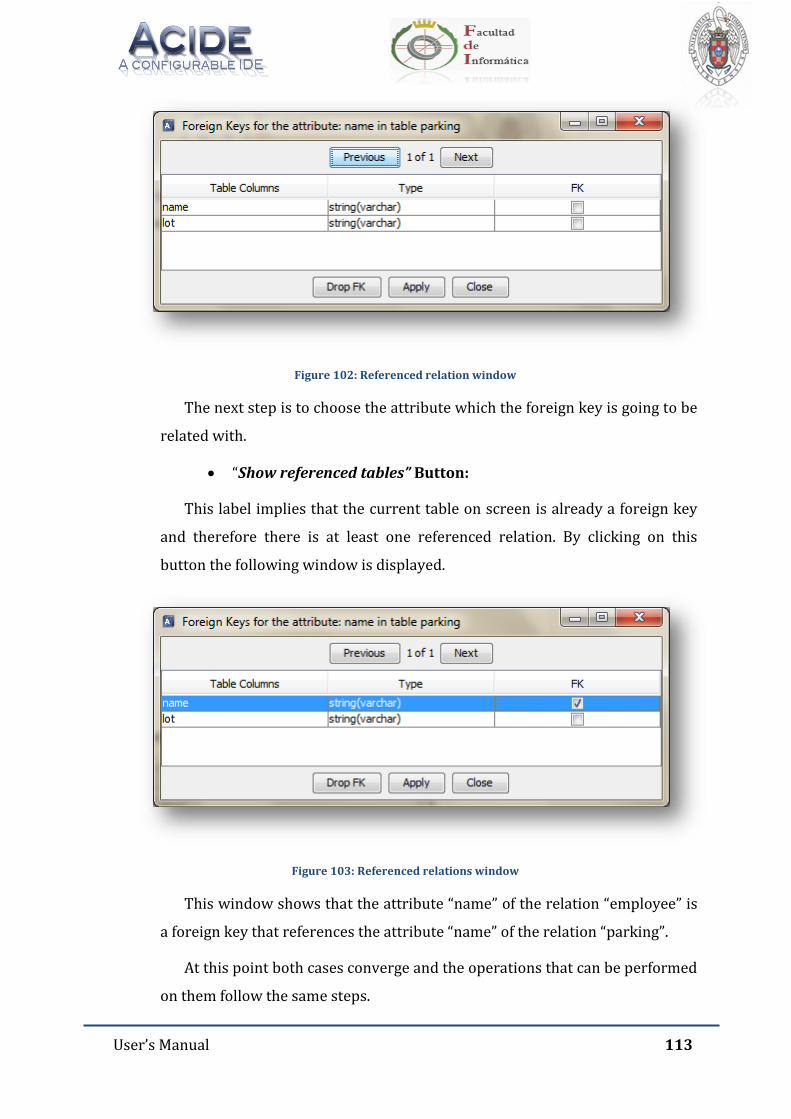
User’s Manual 113
Figure 102: Referenced relation window
The next step is to choose the attribute which the foreign key is going to be
related with.
“Show referenced tables” Button:
This label implies that the current table on screen is already a foreign key
and therefore there is at least one referenced relation. By clicking on this
button the following window is displayed.
Figure 103: Referenced relations window
This window shows that the attribute “name” of the relation “employee” is
a foreign key that references the attribute “name” of the relation “parking”.
At this point both cases converge and the operations that can be performed
on them follow the same steps.
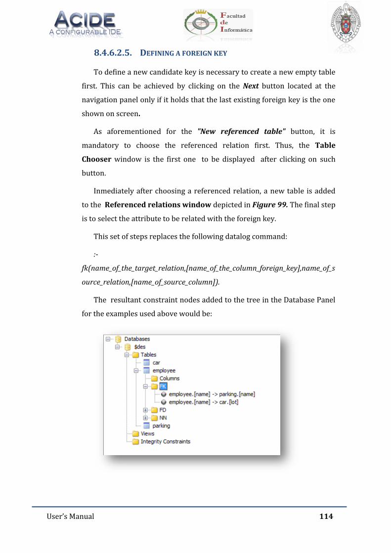
User’s Manual 114
8.4.6.2.5. DEFINING A FOREIGN KEY
To define a new candidate key is necessary to create a new empty table
first. This can be achieved by clicking on the Next button located at the
navigation panel only if it holds that the last existing foreign key is the one
shown on screen.
As aforementioned for the "New referenced table" button, it is
mandatory to choose the referenced relation first. Thus, the Table
Chooser window is the first one to be displayed after clicking on such
button.
Inmediately after choosing a referenced relation, a new table is added
to the Referenced relations window depicted in Figure 99. The final step
is to select the attribute to be related with the foreign key.
This set of steps replaces the following datalog command:
:-
fk(name_of_the_target_relation,[name_of_the_column_foreign_key],name_of_s
ource_relation,[name_of_source_column]).
The resultant constraint nodes added to the tree in the Database Panel
for the examples used above would be:
User’s Manual 115
8.4.6.2.6. MODIFYING A FOREIGN KEY
To modify an existing foreign key, the user must select or deselect the
attribute that is target for modifications on the Referenced relations
window and apply the changes.
This operation basically works deleting the original foreign key and
then defining the new one.
8.4.6.2.7. DELETING A FOREIGN KEY
To delete an existing foreign key the user can either deselect the
attribute or attributes that compound the foreign key or click on the Drop
FK button in the Referenced relations window (Fig. 99).
This action will delete only that specific constraints but not the others
in case there are more.
To delete all the existing relations associated to a foreign key in the
Foreing Key Panel, the user must click on the Drop FK button of this
panel. This button will be updated and the label "New referenced table"
will be set.
It is important to keep in mind that user changes only affect to the table
shown in the current screen, namely, all changes performed must be saved
before switching to any other foreign key screen or panel.
8.4.6.3. NOT NULL PANEL (NN)
A Not Null constraint specifies that the values in a given set of columns of a
relation must not be null.
As its name suggests, this panel allows the user to set the Not Null
restriction to the attributes of a given relation.
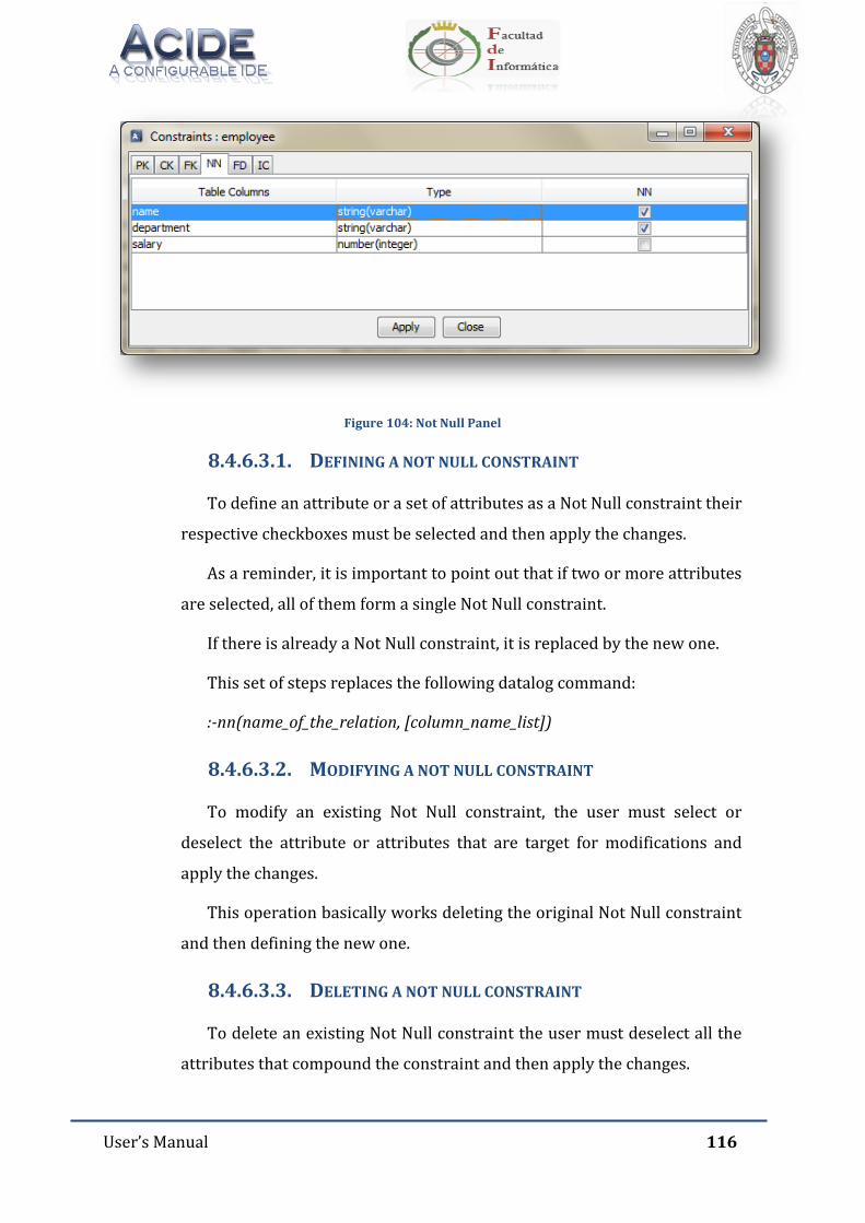
User’s Manual 116
Figure 104: Not Null Panel
8.4.6.3.1. DEFINING A NOT NULL CONSTRAINT
To define an attribute or a set of attributes as a Not Null constraint their
respective checkboxes must be selected and then apply the changes.
As a reminder, it is important to point out that if two or more attributes
are selected, all of them form a single Not Null constraint.
If there is already a Not Null constraint, it is replaced by the new one.
This set of steps replaces the following datalog command:
:-nn(name_of_the_relation, [column_name_list])
8.4.6.3.2. MODIFYING A NOT NULL CONSTRAINT
To modify an existing Not Null constraint, the user must select or
deselect the attribute or attributes that are target for modifications and
apply the changes.
This operation basically works deleting the original Not Null constraint
and then defining the new one.
8.4.6.3.3. DELETING A NOT NULL CONSTRAINT
To delete an existing Not Null constraint the user must deselect all the
attributes that compound the constraint and then apply the changes.
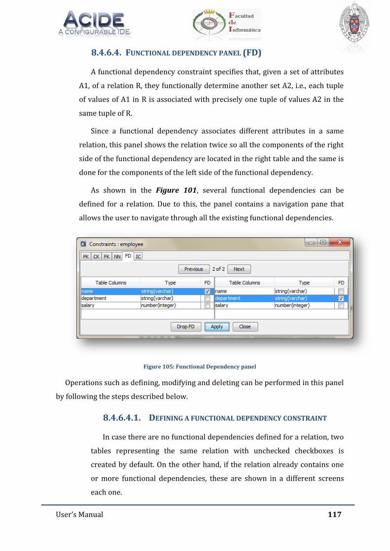
User’s Manual 117
8.4.6.4. FUNCTIONAL DEPENDENCY PANEL (FD)
A functional dependency constraint specifies that, given a set of attributes
A1, of a relation R, they functionally determine another set A2, i.e., each tuple
of values of A1 in R is associated with precisely one tuple of values A2 in the
same tuple of R.
Since a functional dependency associates different attributes in a same
relation, this panel shows the relation twice so all the components of the right
side of the functional dependency are located in the right table and the same is
done for the components of the left side of the functional dependency.
As shown in the Figure 101, several functional dependencies can be
defined for a relation. Due to this, the panel contains a navigation pane that
allows the user to navigate through all the existing functional dependencies.
Figure 105: Functional Dependency panel
Operations such as defining, modifying and deleting can be performed in this panel
by following the steps described below.
8.4.6.4.1. DEFINING A FUNCTIONAL DEPENDENCY CONSTRAINT
In case there are no functional dependencies defined for a relation, two
tables representing the same relation with unchecked checkboxes is
created by default. On the other hand, if the relation already contains one
or more functional dependencies, these are shown in a different screens
each one.
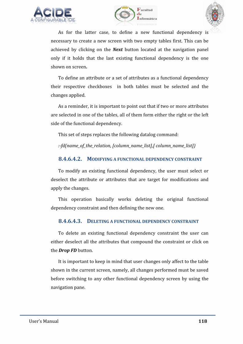
User’s Manual 118
As for the latter case, to define a new functional dependency is
necessary to create a new screen with two empty tables first. This can be
achieved by clicking on the Next button located at the navigation panel
only if it holds that the last existing functional dependency is the one
shown on screen.
To define an attribute or a set of attributes as a functional dependency
their respective checkboxes in both tables must be selected and the
changes applied.
As a reminder, it is important to point out that if two or more attributes
are selected in one of the tables, all of them form either the right or the left
side of the functional dependency.
This set of steps replaces the following datalog command:
:-fd(name_of_the_relation, [column_name_list],[ column_name_list])
8.4.6.4.2. MODIFYING A FUNCTIONAL DEPENDENCY CONSTRAINT
To modify an existing functional dependency, the user must select or
deselect the attribute or attributes that are target for modifications and
apply the changes.
This operation basically works deleting the original functional
dependency constraint and then defining the new one.
8.4.6.4.3. DELETING A FUNCTIONAL DEPENDENCY CONSTRAINT
To delete an existing functional dependency constraint the user can
either deselect all the attributes that compound the constraint or click on
the Drop FD button.
It is important to keep in mind that user changes only affect to the table
shown in the current screen, namely, all changes performed must be saved
before switching to any other functional dependency screen by using the
navigation pane.
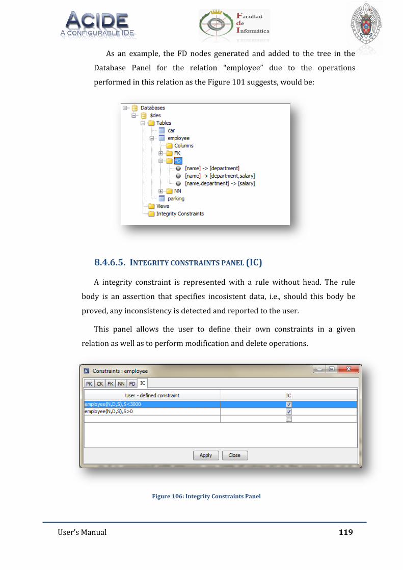
User’s Manual 119
As an example, the FD nodes generated and added to the tree in the
Database Panel for the relation “employee” due to the operations
performed in this relation as the Figure 101 suggests, would be:
8.4.6.5. INTEGRITY CONSTRAINTS PANEL (IC)
A integrity constraint is represented with a rule without head. The rule
body is an assertion that specifies incosistent data, i.e., should this body be
proved, any inconsistency is detected and reported to the user.
This panel allows the user to define their own constraints in a given
relation as well as to perform modification and delete operations.
Figure 106: Integrity Constraints Panel
User’s Manual 120
Since the constraints are defined by the user these cannot be fit into a
specific structure as seen in the previous panels. Thus, this panel implements a
table with two columns, the first one is intended to be filled with the user
defined constraints and the second one to validate any operation that can be
performed on a constraint.
The cells of the first column are editable, so the user can insert and edit
their constraints at any time. The only requeriment to validate these
operations is first to check the corresponding checkbox and after apply the
changes.
Several constraints can be defined in a relation for this reason there is
always an empty row at the end of the table. Every time this row is filled with a
restriction a new empty row is generated letting the user to define more
constraints inmediately.
8.4.6.5.1. DEFINING A USER DEFINED CONSTRAINT
The cells of the first column are editable, so the user can insert their
constraints by clicking twice on an empty cell. The only requeriment to
validate this operation is first to check the corresponding checkbox and
after apply the changes.
Several constraints can be defined in a relation for this reason there is
always an empty row at the end of the table. Every time this row is filled
with a restriction a new empty row is generated letting the user to define
more constraints inmediately.
8.4.6.5.2. MODIFYING A USER DEFINED CONSTRAINT
To modify an existing user defined constraint the user must select or
deselect the corresponding checkbox of the constraints that are target for
modifications and apply the changes.
Previously, the constraint must be modified by clicking twice on its cell
container and editing its content.
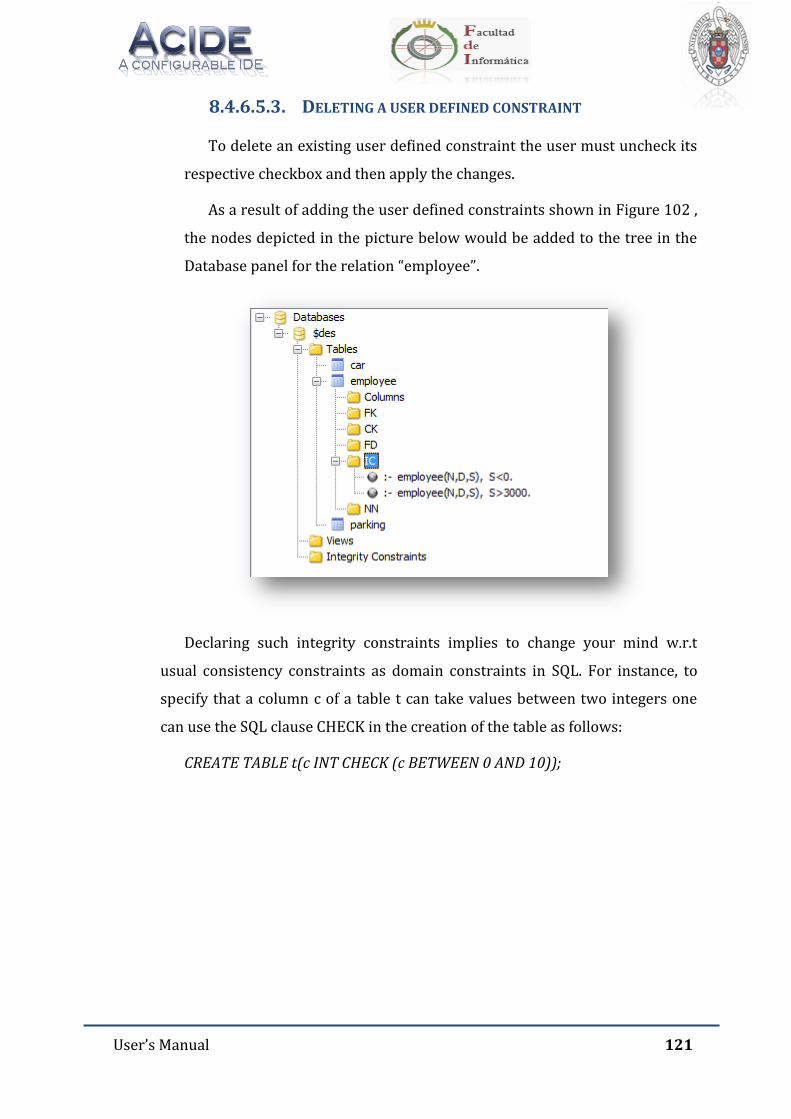
User’s Manual 121
8.4.6.5.3. DELETING A USER DEFINED CONSTRAINT
To delete an existing user defined constraint the user must uncheck its
respective checkbox and then apply the changes.
As a result of adding the user defined constraints shown in Figure 102 ,
the nodes depicted in the picture below would be added to the tree in the
Database panel for the relation “employee”.
Declaring such integrity constraints implies to change your mind w.r.t
usual consistency constraints as domain constraints in SQL. For instance, to
specify that a column c of a table t can take values between two integers one
can use the SQL clause CHECK in the creation of the table as follows:
CREATE TABLE t(c INT CHECK (c BETWEEN 0 AND 10));
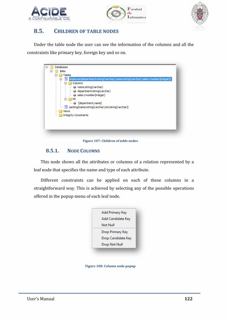
User’s Manual 122
8.5. CHILDREN OF TABLE NODES
Under the table node the user can see the information of the columns and all the
constraints like primary key, foreign key and so on.
Figure 107: Children of table nodes
8.5.1. NODE COLUMNS
This node shows all the attributes or columns of a relation represented by a
leaf node that specifies the name and type of each attribute.
Different constraints can be applied on each of these columns in a
straightforward way. This is achieved by selecting any of the possible operations
offered in the popup menu of each leaf node.
Figure 108: Column node popup
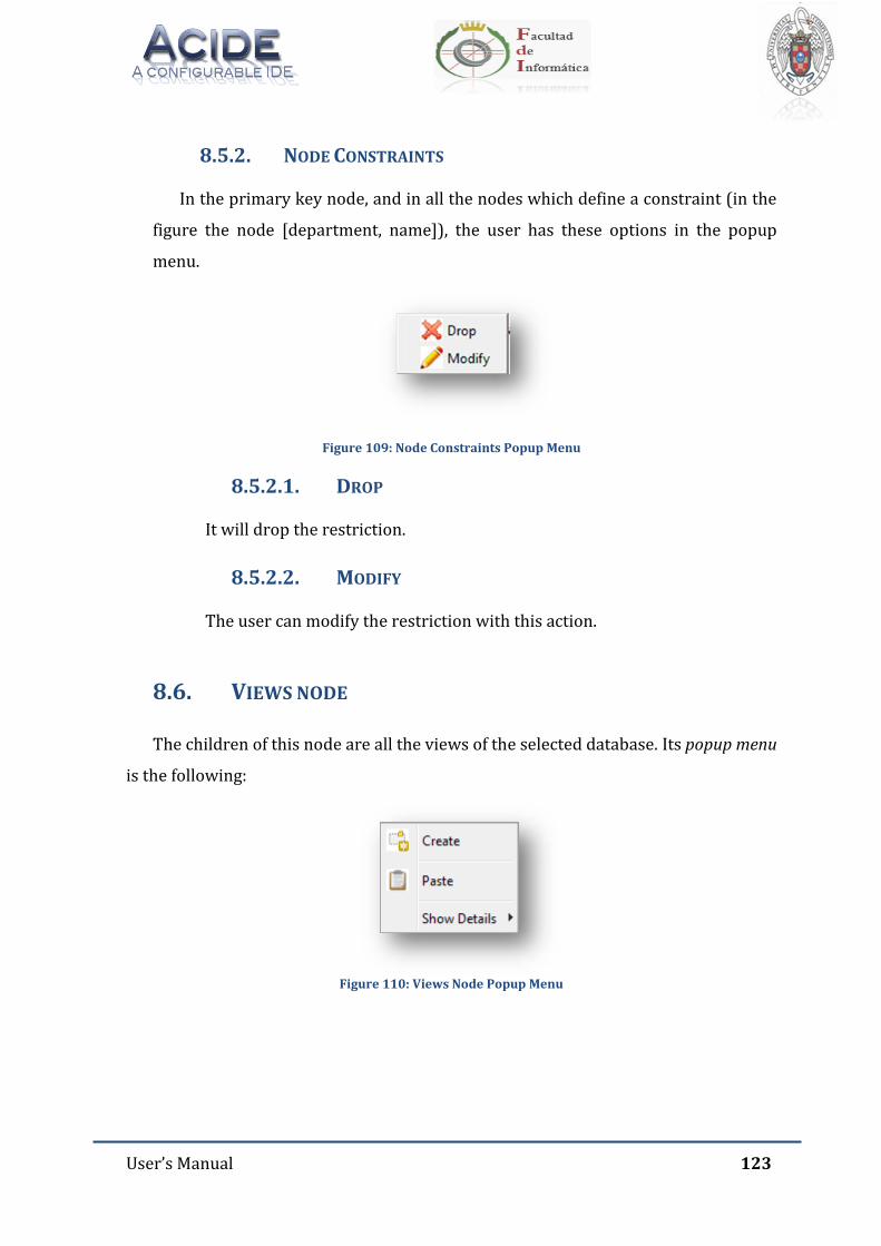
User’s Manual 123
8.5.2. NODE CONSTRAINTS
In the primary key node, and in all the nodes which define a constraint (in the
figure the node [department, name]), the user has these options in the popup
menu.
Figure 109: Node Constraints Popup Menu
8.5.2.1. DROP
It will drop the restriction.
8.5.2.2. MODIFY
The user can modify the restriction with this action.
8.6. VIEWS NODE
The children of this node are all the views of the selected database. Its popup menu
is the following:
Figure 110: Views Node Popup Menu
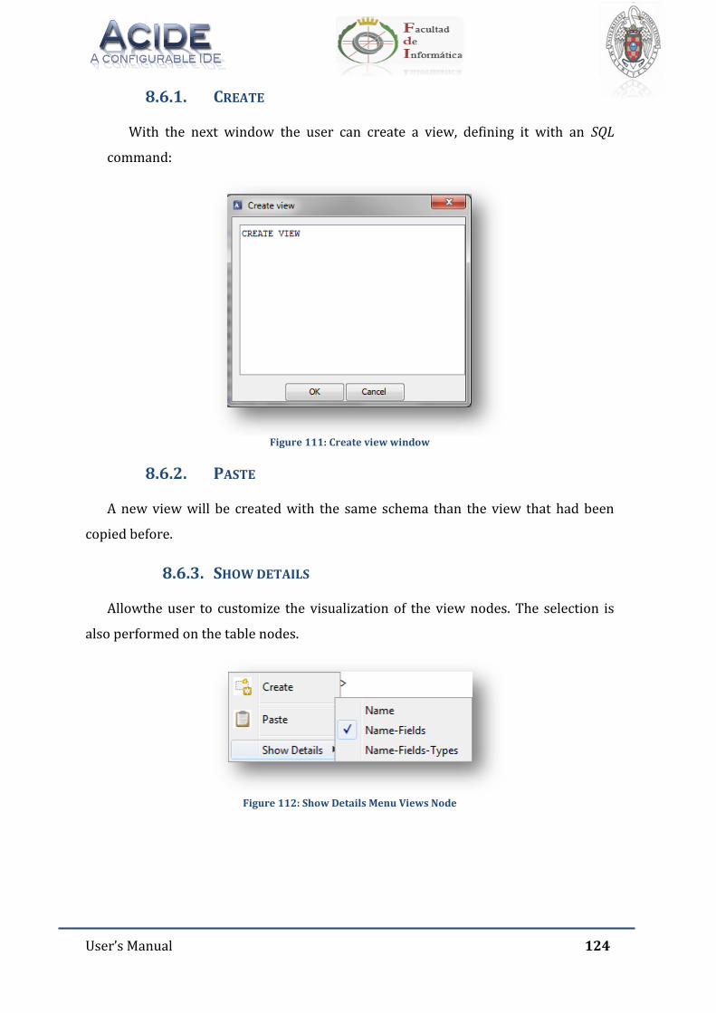
User’s Manual 124
8.6.1. CREATE
With the next window the user can create a view, defining it with an SQL
command:
Figure 111: Create view window
8.6.2. PASTE
A new view will be created with the same schema than the view that had been
copied before.
8.6.3. SHOW DETAILS
Allowthe user to customize the visualization of the view nodes. The selection is
also performed on the table nodes.
Figure 112: Show Details Menu Views Node
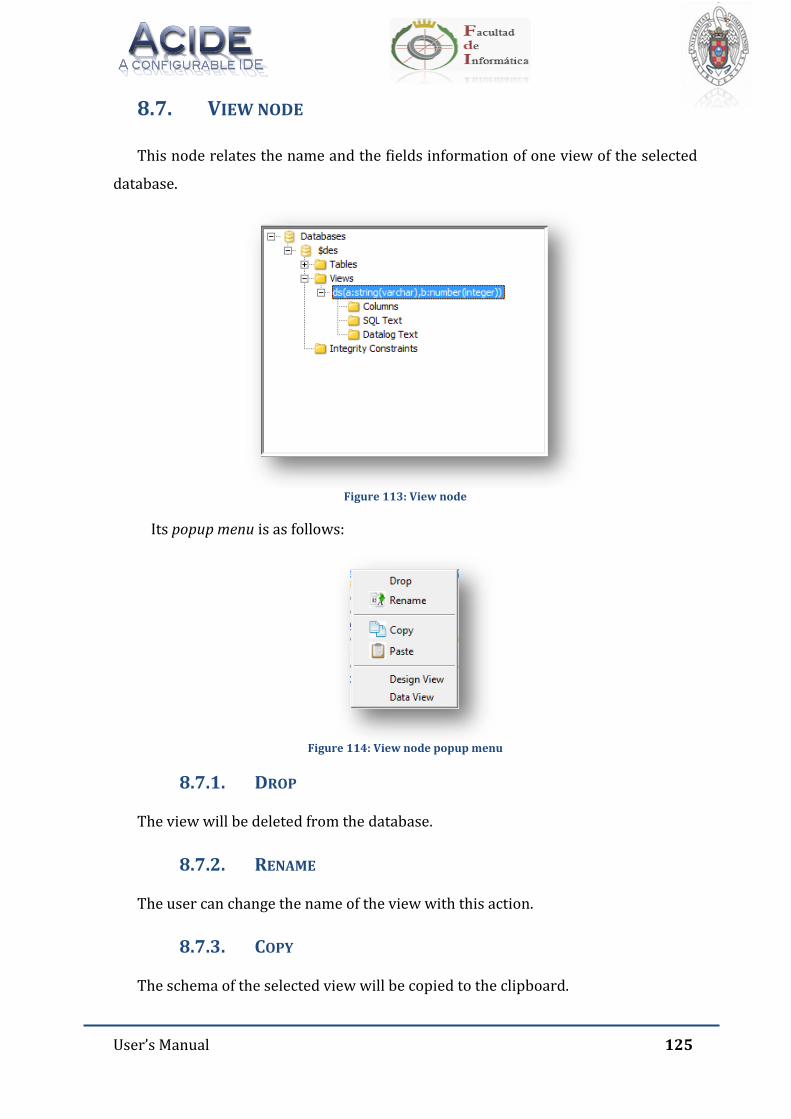
User’s Manual 125
8.7. VIEW NODE
This node relates the name and the fields information of one view of the selected
database.
Figure 113: View node
Its popup menu is as follows:
Figure 114: View node popup menu
8.7.1. DROP
The view will be deleted from the database.
8.7.2. RENAME
The user can change the name of the view with this action.
8.7.3. COPY
The schema of the selected view will be copied to the clipboard.
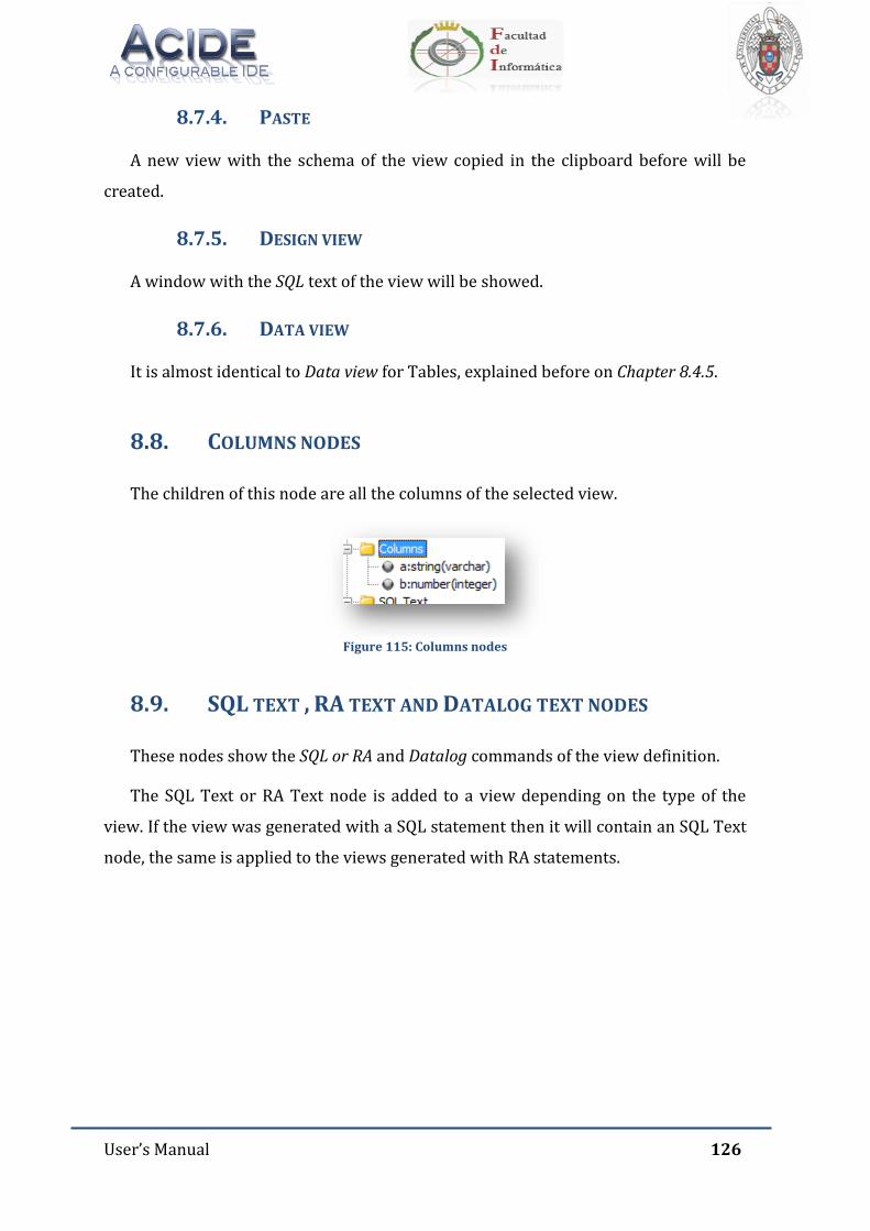
User’s Manual 126
8.7.4. PASTE
A new view with the schema of the view copied in the clipboard before will be
created.
8.7.5. DESIGN VIEW
A window with the SQL text of the view will be showed.
8.7.6. DATA VIEW
It is almost identical to Data view for Tables, explained before on Chapter 8.4.5.
8.8. COLUMNS NODES
The children of this node are all the columns of the selected view.
Figure 115: Columns nodes
8.9. SQL TEXT , RA TEXT AND DATALOG TEXT NODES
These nodes show the SQL or RA and Datalog commands of the view definition.
The SQL Text or RA Text node is added to a view depending on the type of the
view. If the view was generated with a SQL statement then it will contain an SQL Text
node, the same is applied to the views generated with RA statements.
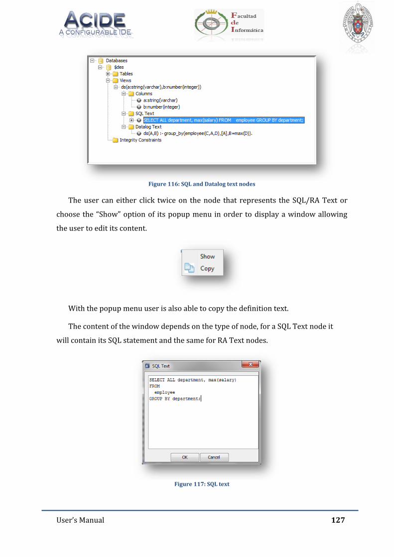
User’s Manual 127
Figure 116: SQL and Datalog text nodes
The user can either click twice on the node that represents the SQL/RA Text or
choose the “Show” option of its popup menu in order to display a window allowing
the user to edit its content.
With the popup menu user is also able to copy the definition text.
The content of the window depends on the type of node, for a SQL Text node it
will contain its SQL statement and the same for RA Text nodes.
Figure 117: SQL text
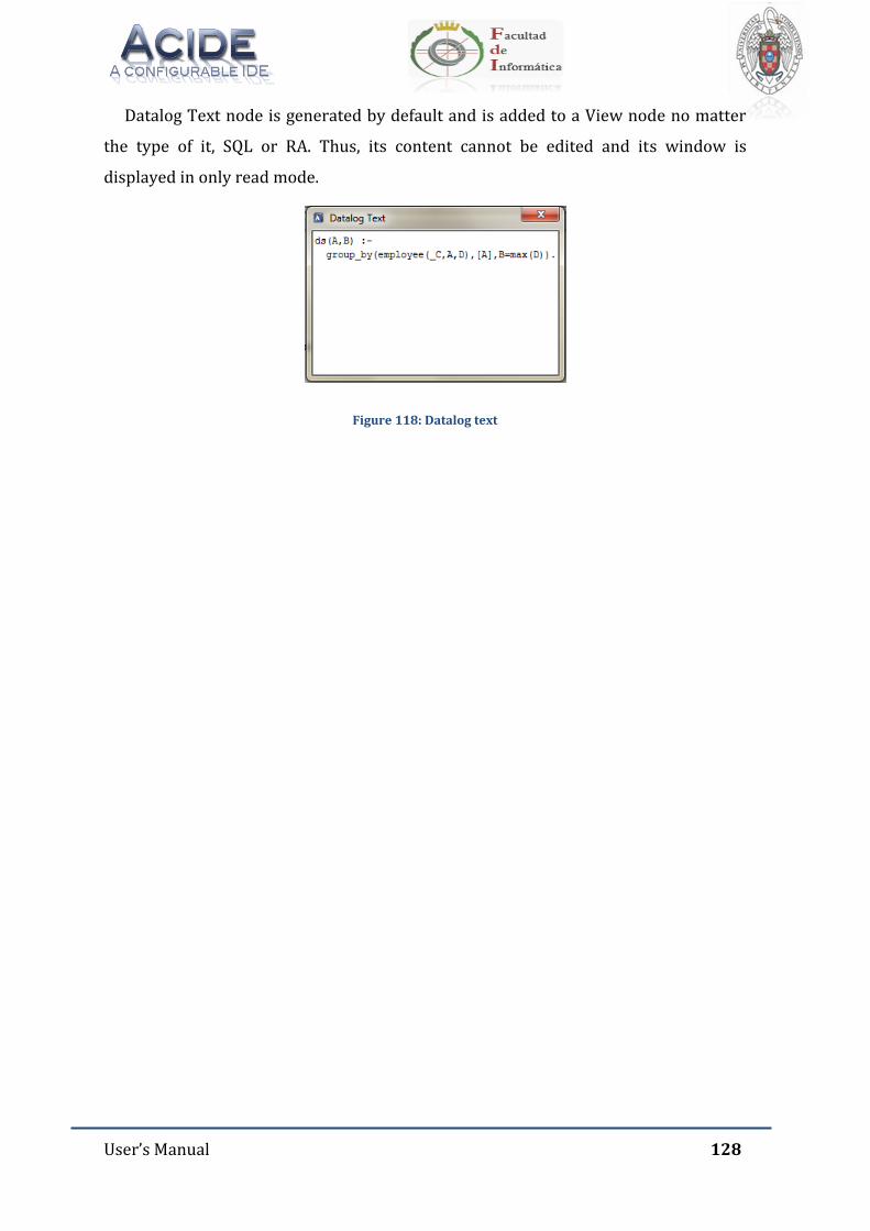
User’s Manual 128
Datalog Text node is generated by default and is added to a View node no matter
the type of it, SQL or RA. Thus, its content cannot be edited and its window is
displayed in only read mode.
Figure 118: Datalog text
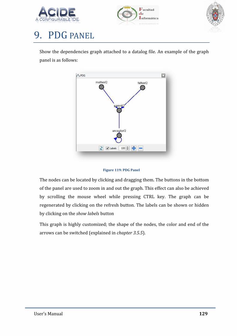
User’s Manual 129
9. PDG PANEL
Show the dependencies graph attached to a datalog file. An example of the graph
panel is as follows:
Figure 119: PDG Panel
The nodes can be located by clicking and dragging them. The buttons in the bottom
of the panel are used to zoom in and out the graph. This effect can also be achieved
by scrolling the mouse wheel while pressing CTRL key. The graph can be
regenerated by clicking on the refresh button. The labels can be shown or hidden
by clicking on the show labels button
This graph is highly customized; the shape of the nodes, the color and end of the
arrows can be switched (explained in chapter 3.5.5).
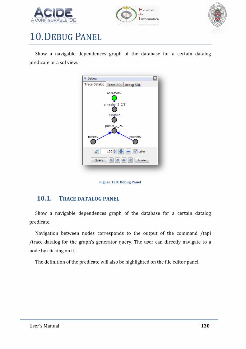
User’s Manual 130
10. DEBUG PANEL
Show a navigable dependences graph of the database for a certain datalog
predicate or a sql view.
Figure 120: Debug Panel
10.1. TRACE DATALOG PANEL
Show a navigable dependences graph of the database for a certain datalog
predicate.
Navigation between nodes corresponds to the output of the command /tapi
/trace_datalog for the graph’s generator query. The user can directly navigate to a
node by clicking on it.
The definition of the predicate will also be highlighted on the file editor panel.
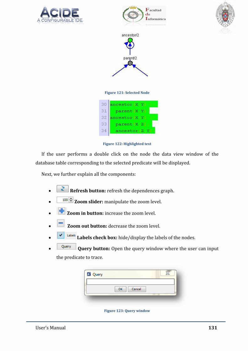
User’s Manual 131
Figure 121: Selected Node
Figure 122: Highlighted text
If the user performs a double click on the node the data view window of the
database table corresponding to the selected predicate will be displayed.
Next, we further explain all the components:
Refresh button: refresh the dependences graph.
Zoom slider: manipulate the zoom level.
Zoom in button: increase the zoom level.
Zoom out button: decrease the zoom level.
Labels check box: hide/display the labels of the nodes.
Query button: Open the query window where the user can input
the predicate to trace.
Figure 123: Query window
User’s Manual 132
Previous node button: Go to the previous node according to the
/trace_datalog command.
Next node button: Go to the next node according to the /trace_datalog
command.
First node button: Go to the first node according to the /trace_datalog
command.
Last node button: Go to the last node according to the /trace_datalog
command.
Rules check box: Highlight/unhighlight the text on the file editor
panel.
Locate button: Show the text corresponding to the selected node
of the graph on the file editor panel.
10.2. TRACE SQL PANEL
Show a navigable dependences graph of the database for a certain sql view.
Navigation between nodes corresponds to the output of the command /tapi
/trace_sql for the graph’s generator query. The user can directly navigate to a node by
clicking on it.
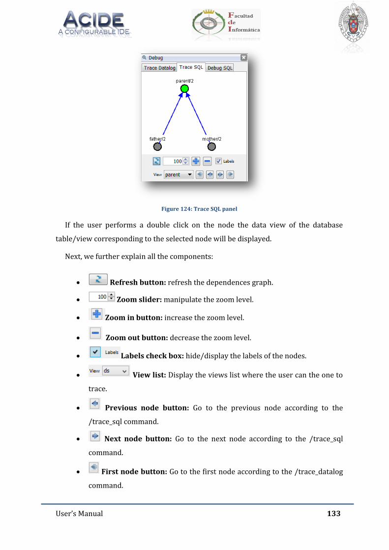
User’s Manual 133
Figure 124: Trace SQL panel
If the user performs a double click on the node the data view of the database
table/view corresponding to the selected node will be displayed.
Next, we further explain all the components:
Refresh button: refresh the dependences graph.
Zoom slider: manipulate the zoom level.
Zoom in button: increase the zoom level.
Zoom out button: decrease the zoom level.
Labels check box: hide/display the labels of the nodes.
View list: Display the views list where the user can the one to
trace.
Previous node button: Go to the previous node according to the
/trace_sql command.
Next node button: Go to the next node according to the /trace_sql
command.
First node button: Go to the first node according to the /trace_datalog
command.
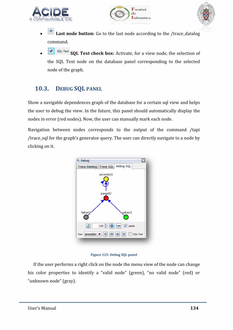
User’s Manual 134
Last node button: Go to the last node according to the /trace_datalog
command.
SQL Text check box: Activate, for a view node, the selection of
the SQL Text node on the database panel corresponding to the selected
node of the graph.
10.3. DEBUG SQL PANEL
Show a navigable dependences graph of the database for a certain sql view and helps
the user to debug the view. In the future, this panel should automatically display the
nodes in error (red nodes). Now, the user can manually mark each node.
Navigation between nodes corresponds to the output of the command /tapi
/trace_sql for the graph’s generator query. The user can directly navigate to a node by
clicking on it.
Figure 125: Debug SQL panel
If the user performs a right click on the node the menu view of the node can change
his color properties to identify a “valid node” (green), “no valid node” (red) or
“unknown node” (gray).
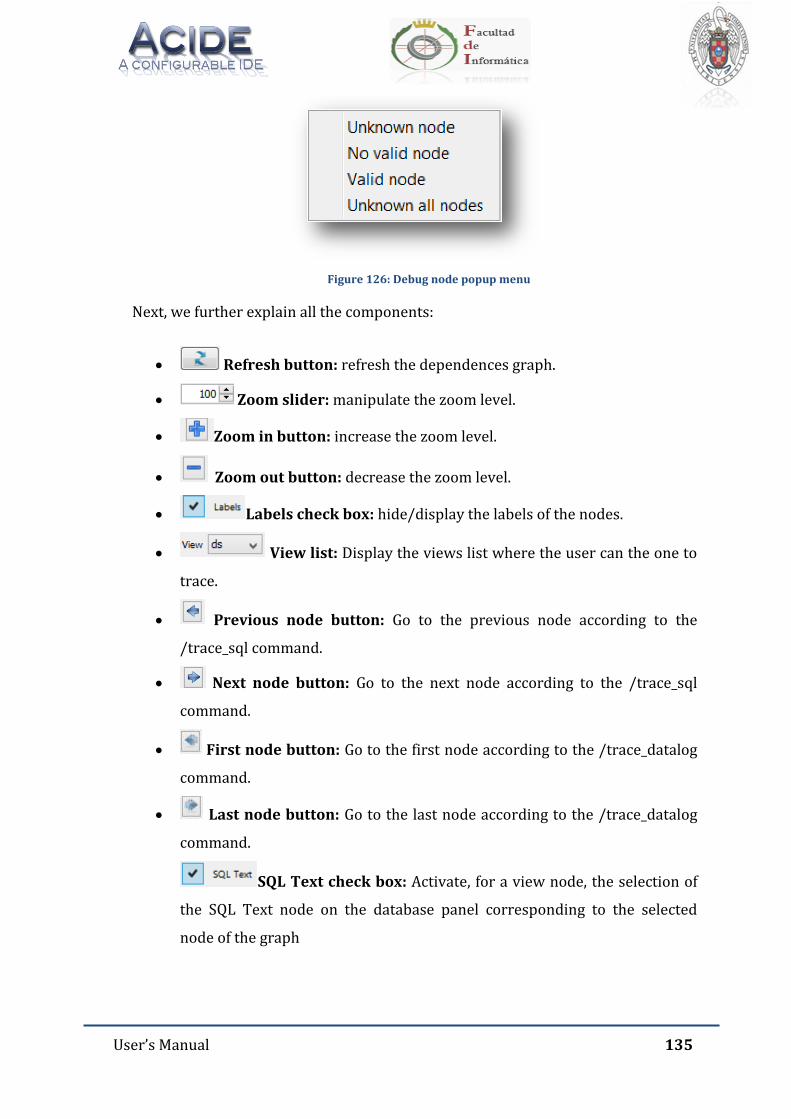
User’s Manual 135
Figure 126: Debug node popup menu
Next, we further explain all the components:
Refresh button: refresh the dependences graph.
Zoom slider: manipulate the zoom level.
Zoom in button: increase the zoom level.
Zoom out button: decrease the zoom level.
Labels check box: hide/display the labels of the nodes.
View list: Display the views list where the user can the one to
trace.
Previous node button: Go to the previous node according to the
/trace_sql command.
Next node button: Go to the next node according to the /trace_sql
command.
First node button: Go to the first node according to the /trace_datalog
command.
Last node button: Go to the last node according to the /trace_datalog
command.
SQL Text check box: Activate, for a view node, the selection of
the SQL Text node on the database panel corresponding to the selected
node of the graph
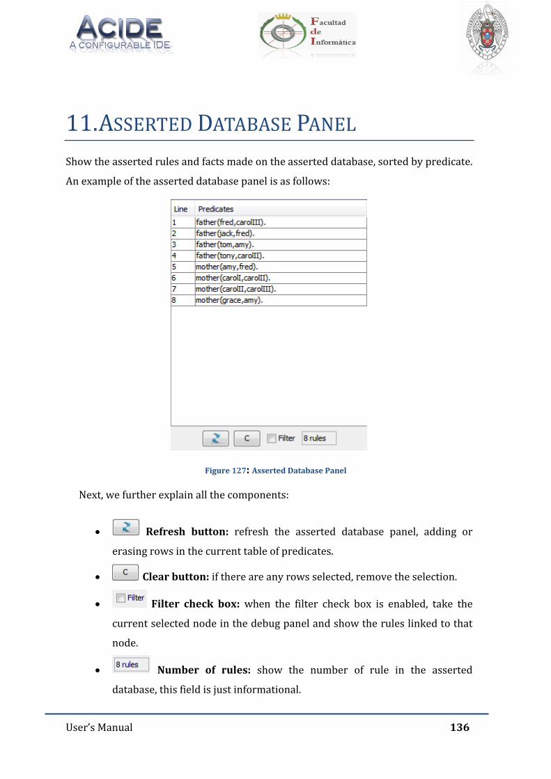
User’s Manual 136
11. ASSERTED DATABASE PANEL
Show the asserted rules and facts made on the asserted database, sorted by predicate.
An example of the asserted database panel is as follows:
Figure 127: Asserted Database Panel
Next, we further explain all the components:
Refresh button: refresh the asserted database panel, adding or
erasing rows in the current table of predicates.
Clear button: if there are any rows selected, remove the selection.
Filter check box: when the filter check box is enabled, take the
current selected node in the debug panel and show the rules linked to that
node.
Number of rules: show the number of rule in the asserted
database, this field is just informational.
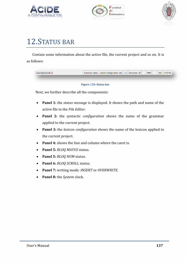
User’s Manual 137
12. STATUS BAR
Contain some information about the active file, the current project and so on. It is
as follows:
Figure 128: Status bar
Next, we further describe all the components:
Panel 1: the status message is displayed. It shows the path and name of the
active file in the File Editor.
Panel 2: the syntactic configuration shows the name of the grammar
applied to the current project.
Panel 3: the lexicon configuration shows the name of the lexicon applied to
the current project.
Panel 4: shows the line and column where the caret is.
Panel 5: BLOQ MAYUS status.
Panel 5: BLOQ NUM status.
Panel 6: BLOQ SCROLL status.
Panel 7: writing mode: INSERT or OVERWRITE.
Panel 8: the System clock.

User’s Manual 138
13. ACCESSIBILITY SHORTCUTS
The application offers some accessibility shortcuts to wrapper common user
actions such as:
F3 + Selected text: performs the forward text search with the selected text
in the file editor, in the console panel or in the data view window.
F3 + Shift + Selected text: performs the backward text search with the
selected text in the file editor, in the console panel or in the data view
window.
Mouse wheel: performs the vertical scroll line by line in the file editor and
console panel.
Control + mouse wheel: performs the zoom effect for the font size in the
file editor, console panel and graph panel.
Shift + Tab: in case a Tab action has been performed, undo the action.
Others accessibility shortcuts depends on the language of the application.
13.1. ACCESSIBILITY SHORTCUTS IN ENGLISH
Shortcuts in File menu:
Ctrl + N: Create new file.
Ctrl + O: Open a file.
Ctrl + S: Save active file in the file editor.
Ctrl + Shift + S: Save all files in the file editor.
Ctrl + P : Print active file in the file editor.
Alt + X: Close the application.
Shortcuts in Edit menu:
Ctrl + Z: Undo the last action.
Ctrl + Y: Redo the last change.
Ctrl + C: Copy the selected text to the System clipboard.
User’s Manual 139
Ctrl + X: Cut the selected text to the System clipboard.
Ctrl + V: Paste the test in the System clipboard.
Ctrl + E: Select all the text in the active file of the file editor.
Ctrl + F: Open the search window.
Ctrl + R: Open the replace window.
Ctrl + U: Transforms to uppercase a given text.
Ctrl + L: Transforms to lowercase a given text.
Ctrl + Shift + U: Capitalize every word in a given text.
Ctrl + Shift + L: Alternates between uppercase and lowercase every word
in a given text.
F9: Send file content to Console.
Shortcuts in Project menu:
Alt + Shift + N: Create a new project.
Alt + Shift + O: Open a project.
Alt + Shift + S: Save the opened project.
Alt + Shift + A: Add a file to the opened project.
Alt + C: Compile the opened project.
Alt + E: Execute the opened project.
Shortcuts in View menu:
Alt + Shift + L: Show the log tab.
Shortcuts in Configuration menu:
Ctrl + Shift + L: Documents lexicon.
Ctrl + Shift + X: Modifiy the lexicon.
Ctrl + Shift + T: Create a new grammar.
Ctrl + Shift + A: Active line wrapping.
Ctrl + Shift + F: Open the search in console window.
Shortcuts in Help menu:

User’s Manual 140
Ctrl + H: Show this document.
Shortcuts in Data view:
Up arrow: Go to previous record.
Down arrow: Go to next record.
Tab: Go to next field.
Shift + Tab: Go to previous field.
Alt + F4: Close the Data view window.
Ctrl + Z: Undo the updates in the grid.
Ctrl + Y: Redo the last undo in the grid.
Ctrl + C: Copy the selected data from the grid to the System clipboard.
Ctrl + V: Paste the data stored in the System clipboard in the current
position of the cursor in the grid.
Ctrl + X: Cut the selected text active field from the grid to the System
clipboard.
Ctrl + F: Show the search text window for the Data view.
F5: Refresh the view of the grid.
Ctrl + home: Go to the first record.
Ctrl + end: Go to the last record.
Ctrl + H: Link directly to the present document.
Shortcuts in Menu configuration:
Up arrow: Select previous object.
Down arrow: Select next object.
Ctrl + Home: Select the first object.
Ctrl + End: Select the last object.
Tab: Select next attribute.
Tab + Shift: Select previous attribute.
Esc: Deselect the selected object.
Shorcuts in asserted database:
Alt + F4: Close the window.
User’s Manual 141
F5: Refresh the asserted database panel.
C: Remove the current selection of the rows.
Shortcuts in database panel:
Supr: Deletes a selected view o table.
Ctrl + C: Copies the selected node and its content if available.
Ctrl + V: Paste the seleceted node and its content if available.
13.2. ACCESSIBILITY SHORTCUTS IN SPANISH
Shortcuts in File menu:
Ctrl + N: Create new file.
Ctrl + O: Open a file.
Ctrl + G: Save active file in the file editor.
Ctrl + Shift + G: Save all files in the file editor.
Ctrl + P : Print active file in the file editor.
Alt + X: Close the application.
Shortcuts in Edit menu:
Ctrl + Z: Undo the last action.
Ctrl + Y: Redo the last change.
Ctrl + C: Copy the selected text to the System clipboard.
Ctrl + X: Cut the selected text to the System clipboard.
Ctrl + V: Paste the test in the System clipboard.
Ctrl + E: Select all the text in the active file of the file editor.
Ctrl + B: Open the search window.
Ctrl + R: Open the replace window.
Ctrl + U: Transforms to uppercase a given text.
Ctrl + L: Transforms to lowercase a given text.
Ctrl + Mayús + U: Capitalize every word in a given text.
User’s Manual 142
Ctrl + Mayús + L: Alternates between uppercase and lowercase every word
in a given text.
Shortcuts in Project menu:
Alt + Shift + N: Create a new project.
Alt + Shift + O: Open a project.
Alt + Shift + S: Save the opened project.
Alt + Shift + A: Add a file to the opened project.
Alt + C: Compile the opened project.
Alt + E: Execute the opened project.
Shortcuts in View menu:
Alt + Shift + L: Show the log tab.
Shortcuts in Configuration menu:
Ctrl + Shift + L: Document lexicon.
Ctrl + Shift + X: Modifiy the lexicon.
Ctrl + Shift + T: Create a new grammar.
Ctrl + Shift + A: Active line wrapping.
Ctrl + Shift + F: Open the search in console window.
Shortcuts in Help menu:
Ctrl + H: Show this document.
Shortcuts in Data view:
Up arrow: Go to previous record.
Down arrow: Go to next record.
Tab: Go to next field.
Shift + Tab: Go to previous field.
Alt + F4: Close the Data view window.

User’s Manual 143
Ctrl + Z: Undo the updates in the grid.
Ctrl + Y: Redo the last undo in the grid.
Ctrl + C: Copy the selected data from the grid to the System clipboard.
Ctrl + V: Paste the data stored in the System clipboard in the current
position of the cursor in the grid.
Ctrl + X: Cut the selected text active field from the grid to the System
clipboard.
Ctrl + F: Show the search text window for the Data view.
F5: Refresh the view of the grid.
Ctrl + home: Go to the first record.
Ctrl + end: Go to the last record.
Ctrl + H: Link directly to the present document.
Shortcuts in Menu configuration:
Up arrow: Select previous object.
Down arrow: Select next object.
Ctrl + Home: Select the first object.
Ctrl + End: Select the last object.
Tab: Select next attribute.
Tab + Shift: Select previous attribute.
Esc: Deselect the selected object.
Shorcuts in asserted database:
Alt + F4: Close the window.
F5: Refresh the asserted database panel.
C: Remove the current selection of the rows.
Shortcuts in database panel:
Supr: Deletes a selected view o table.
Ctrl + C: Copies the selected node and its content if available.
Ctrl + V: Paste the seleceted node and its content if available.
User’s Manual 144
13.3. ACCESSIBILITY SHORTCUTS IN FRENCH
Shortcuts in File menu:
Ctrl + N: Create new file.
Ctrl + O: Open a file.
Ctrl + S: Save active file in the file editor.
Ctrl + Shift + S: Save all files in the file editor.
Ctrl + P : Print active file in the file editor.
Alt + X: Close the application.
Shortcuts in Edit menu:
Ctrl + Z: Undo the last action.
Ctrl + Y: Redo the last change.
Ctrl + C: Copy the selected text to the System clipboard.
Ctrl + X: Cut the selected text to the System clipboard.
Ctrl + V: Paste the test in the System clipboard.
Ctrl + E: Select all the text in the active file of the file editor.
Ctrl + F: Open the search window.
Ctrl + R: Open the replace window.
Ctrl + U: Transforms to uppercase a given text.
Ctrl + L: Transforms to lowercase a given text.
Ctrl + Shift + U: Capitalize every word in a given text.
Ctrl + Shift + L: Alternates between uppercase and lowercase every word
in a given text.
F9: Send file content to Console.
Shortcuts in Project menu:
Alt + Shift + N: Create a new project.
Alt + Shift + O: Open a project.
Alt + Shift + S: Save the opened project.
Alt + Shift + A: Add a file to the opened project.
User’s Manual 145
Alt + C: Compile the opened project.
Alt + E: Execute the opened project.
Shortcuts in View menu:
Alt + Shift + L: Show the log tab.
Shortcuts in Configuration menu:
Ctrl + Shift + L: Documents lexicon.
Ctrl + Shift + X: Modifiy the lexicon.
Ctrl + Shift + T: Create a new grammar.
Ctrl + Shift + A: Active line wrapping.
Ctrl + Shift + F: Open the search in console window.
Shortcuts in Help menu:
Ctrl + H: Show this document.
Shortcuts in Data view:
Up arrow: Go to previous record.
Down arrow: Go to next record.
Tab: Go to next field.
Shift + Tab: Go to previous field.
Alt + F4: Close the Data view window.
Ctrl + Z: Undo the updates in the grid.
Ctrl + Y: Redo the last undo in the grid.
Ctrl + C: Copy the selected data from the grid to the System clipboard.
Ctrl + V: Paste the data stored in the System clipboard in the current
position of the cursor in the grid.
Ctrl + X: Cut the selected text active field from the grid to the System
clipboard.
Ctrl + F: Show the search text window for the Data view.
F5: Refresh the view of the grid.
Ctrl + home: Go to the first record.
User’s Manual 146
Ctrl + end: Go to the last record.
Ctrl + H: Link directly to the present document.
Shortcuts in Menu configuration:
Up arrow: Select previous object.
Down arrow: Select next object.
Ctrl + Home: Select the first object.
Ctrl + End: Select the last object.
Tab: Select next attribute.
Tab + Shift: Select previous attribute.
Esc: Deselect the selected object.
Shorcuts in asserted database:
Alt + F4: Close the window.
F5: Refresh the asserted database panel.
C: Remove the current selection of the rows.
Shortcuts in database panel:
Supr: Deletes a selected view o table.
Ctrl + C: Copies the selected node and its content if available.
Ctrl + V: Paste the seleceted node and its content if available.
User’s Manual 147
14. ACIDE VARIABLES
The application supports some variables in the Console Panel, External
Applications Tool Bar and the console loaded in the console panel such as:
$activeFile$: reference the current active file in the file editor panel.
$activeFileName$: reference just the current active name file in the file
editor panel.
$activeFilePath$: reference just the current active path file in the file
editor panel without including neither file name nor file extension.
$activeFileExt$: reference just the current active extension file in the file
editor panel.
$mainFile$: reference the file in the file editor panel that has been marked
as MAIN file.
$mainFilePath$: reference the just file path in the file editor panel that has
been marked has MAIN file without including neither file name nor file
extension.
$mainFileExt$: reference just the file extension in the file editor panel that
has been marked as MAIN file.
User’s Manual 148
15. ACIDE DEFAULT COMMANDS
As explained in Chapter 3.5.10, with the menu configuration the user can assign to
the application the actions that will be executed when menu items are pressed down.
All these commands start with “$”. The commands assigned by default to ACIDE – A
Configurable IDE menu items are:
File menu:
o $NEW_FILE: Create a new file in the file editor.
o $OPEN_FILE: Open a file in the file editor.
o $OPEN_ALL_FILES: Open all the files of the active project.
o $CLOSE_FILE: Close the active file in the file editor.
o $CLOSE_ALL_FILES: Close all files in the file editor.
o $SAVE_FILE: Save the active file.
o $SAVE_FILE_AS: Save the active file in a different path.
o $SAVE_ALL_FILES: Save all the opened files in the file editor.
o $PRINT_FILE: Print the active file in the file editor.
o $EXIT_FILE: Close the application.
Edit menu:
o $UNDO: Undo the last action.
o $REDO: Redo the last undone action.
o $COPY: Copy the selected text to the System clipboard.
o $PASTE: Paste the text in the System clipboard.
o $CUT: Cut the selected text to the System clipboard.
o $TOGGLE_COMMENT: Comment or uncomment the line according
to whether the line is commented or not.
o $MAKE_COMMENT: Comment a line.
o $RELEASE_COMMENT: Uncomment a line.
o $SELECT_ALL: Select all the text in the active file of the file editor.
o $GO_TO_LINE: Open a window where user can type down the
number of line where he or she wants to go.
o $UPPER_CASE: Transform lower case text into upper case.
o $LOWER_CASE: Transform upper case text into lower case.

User’s Manual 149
o $CAPITALIZE: Transform to upper case the first letter of all the
words in a text.
o $INVERT_CASE: Transform to upper case the lower case letters and
viceversa.
o $SEARCH: Open the search window.
o $REPLACE: Open the replace window.
Project menu:
o $NEW_PROJECT: Create a new project.
o $OPEN_PROJECT: Open a project in the application.
o $CLOSE_PROJECT: Close the opened project in the application.
o $SAVE_PROJECT: Save the active project in the application.
o $SAVE_PROJECT_AS: Save the active project in the application with
a different path.
o $ADD_OPENED_FILES: Add all opened files in the application to the
active project.
o $NEW_PROJECT_FILE: Create a new file and adds it to the active
project.
o $ADD_FILE: Add the active file in the file editor to current project.
o $REMOVE_FILE: Remove the active file in the file editor from the
current project.
o $DELETE_FILE: Delete the active file from the current project and
from disk.
o $ADD_FOLDER: Add a folder to the current project.
o $REMOVE_FOLDER: Remove the selected folder from the current
project.
o $COMPILE: Compile the current project.
o $EXECUTE: Execute the current project.
o $SET_COMPILABLE_FILE: Set compilable the selected file.
o $UNSET_COMPILABLE_FILE: Unset compilable the selected file.
o $SET_MAIN_FILE: Set as main file the selected file.
o $UNSET_MAIN_FILE: Unset as main file the selected file.
View menu:
o $SHOW_LOG_TAB: Show the log tab.
User’s Manual 150
o $SHOW_EXPLORER_PANEL: Show or hide the explorer panel.
o $SHOW_CONSOLE_PANEL: Show or hide the console panel.
o $SHOW_DATABASE_PANEL: Show or hide the database panel.
o $SHOW_GRAPH_PANEL: Show or hide the graph panel.
o $SHOW_DEBUG_PANEL: Show or hide the debug panel.
o $SHOW_ASSERTED_DATABASE_PANEL: Open the asserted
database panel.
Configuration menu:
o Lexicon submenu:
$NEW_LEXICON: Open a window where user type down the
name for the new lexicon.
$DOCUMENT_LEXICON: Load the lexicon configuration file
in the active file of the file editor.
$MODIFY_LEXICON: Open the lexicon configuration window.
$DEFAULT_LEXICON: Show the default lexicon configuration
window.
o Grammar submenu:
$NEW_GRAMMAR: Open the new grammar configuration
window.
$LOAD_GRAMMAR: Load a grammar configuration.
$MODIFY_GRAMMAR: Display the modify grammar
configuration window.
$SAVE_GRAMMAR: Save the current grammar configuration
into a file.
$SAVE_GRAMMAR_AS: Save the current grammar
configuration into a file with a different path.
$SET_PATHS: Display the set paths window.
o $COMPILER: Display the compiler configuration window.
o File editor submenu:
$PREFERENCES: Display the preferences window.
$FILE_EDITOR_DISPLAY_OPTIONS: Display the file editor
display configuration window.

User’s Manual 151
$AUTOMATIC_INDENT: Enable or disable the automatic
indent in the file editor.
$LINE_WRAPPING: Enable or disable the line wrapping in
the file editor.
$MAXIMUM_LINES: Ask to the user for the maximum
number of lines to send to the console panel.
$SEND_CONSOLE_CONFIRMATION: Enable or disable the
confirmation request when user sends contents to console
panel.
o Console submenu:
$CONFIGURE_CONSOLE: Open the console configuration
window.
$CONSOLE_DISPLAY_OPTIONS: Display the console display
configuration window.
$CONSOLE_LINE_WRAPPING: Enable or disable the console
line wrapping.
$SAVE_CONSOLE_CONTENT: Save the console content into a
file.
$DOCUMENT_CONSOLE: Load a lexicon configuration into
the console panel.
$SEARCH_CONSOLE: Open the search in console window.
$CLOSE_CONSOLE: Close the console.
o Database panel submenu:
$DES_PANEL: Select the DES conection in database panel.
$ODBC_PANEL: Select the ODBC conection in database panel.
$SHOW_NAME: Only the name of table and view nodes are
shown in the Database Panel.
$SHOW_NAME_FIELDS: Name and columns of table and
view nodes are shown in the Database Panel.
$SHOW_NAME_FIELDS_TYPES: Name, columns and the type
of each column of table and view nodes are shown in the
Database Panel.
o PDG submenu:
User’s Manual 152
$NODES_COLOR: Display a color selection menu to change
the color of the nodes.
$NODES_SIZE: Display a menu to change the size of the
nodes.
$NODES_SHAPE_CIRCLE: Change the shape of the nodes to a
circle.
$NODES_SHAPE_SQUARE: Change the shape of the nodes to
a square.
$ARROW_SHAPE_LINE: Change the sahpe of the tip of the
arrow to lines.
$ARROW_SHAPE_POLYGON: Change the shape of the tip of
the arrow to a triangle.
$ARROW_COLOR_DIRECT: Display a color selection menu to
change the color of the positive depencences arrows.
$ARROW_COLOR_INVERSE: Display a color selection menu
to change the color of the negative depencences arrows.
$SHOW_LABELS: show or hide the labels of the nodes.
o Menu submenu:
$NEW_MENU: Display the new menu configuration window.
$LOAD_MENU: Load a menu configuration and applies it to
application.
$MODIFY_MENU: Display the menu configuration window
for modifying.
$SAVE_MENU: Save the current menu configuration.
$SAVE_MENU_AS: Save the current menu configuration with
a different path.
o Tool bar submenu:
$NEW_TOOLBAR: Display the new toolbar configuration
window.
$LOAD_TOOLBAR: Load a tool bar configuration and applies
it to application.
$MODIFY_TOOLBAR: Display the tool bar configuration
window for modifying.

User’s Manual 153
$SAVE_TOOLBAR: Save the current tool bar configuration.
$SAVE_TOOLBAR_AS: Save the current tool bar
configuration with a different path.
Help menu:
o $SHOW_HELP: Open this document.
o $SHOW_ABOUT_US: Display the About Us window.
These commands can be assigned to other menu items than are not the default
menu items.
User’s Manual 154
16. CONFIGURATION OF ACIDE BY
CONFIGURATION DOCUMENTS
16.1. MANAGERS IN XML FILES
Frequently in XML configuration files we found labels of the form “…Manager”.
These labels contain a type of object called Manager that is responsible for handling
lists of different types of objects. Inside the labels of a Manager there is another label
called “_list” and that in turn holds another label also called “_list”. It is inside this
label where user introduces the labels of the objects that make up the list he wants to
handle with the Manager (could be a list of String, AcideLexiconTokenGroup, etc.).
There are java classes for each of the Managers in XML files, which provide
methods to manipulate the lists as adding, removing or getting items from them.
Manager Java classes have an ObjectList type field, which in turn has an ArrayList field
(where user stores the list of objects) and methods for manipulating that list.
To introduce, delete, reorder, etc. elements of the list, just manually edit the XML
document and operate on the labels of each object.
16.2. PROPERTIES CONFIGURATION
To configure several properties of ACIDE – A Configurable IDE there is a file called
configuration.properties stored in ./configuration. In this file are stored properties
that are not specified in other files. The structure of this file is fixed; user can only edit
the values for each field, but he is not able to add new properties or delete any of the
existing.
The first line of the properties configuration file is:
#ACIDE Configuration
The following line shows the date of the last time the user ran this issue of ACIDE
– A Configurable IDE. Displays the following format:
#Mon May 27 18:16:32 CEST 2013
User’s Manual 155
The following lines show the property name followed by a “=” and the value
assigned to that property with the following structure:
consolePanel.fontName=name of the font of console panel.
workbenchConfiguration=path to XML file that configures the workbench
(Chapter 16.3)
lastOpenedFileDirectory=the folder was last opened. Used to locate the
user in the same folder next time.
javacPath=path of javac.exe.
jarPath=path of jar.exe.
consolePanel.exitCommand=exit command for console.
ed=
consolePanel.fontStyle=style of the font of console panel.
consolePanel.bufferSize=size of buffer of console panel.
previousMenuNewConfiguration=path to XML file that previously
configured ACIDE – A Configurable IDE menu with the new configuration of
version 0.11 (Chapter 16.3.1)
consolePanel.backgroundColor=console panel background color
(numeric valor).
currentMenuConfiguration=path to .menuConfig file that was
configurating ACIDE – A Configurable IDE menu with the configuration of
older versions.
databasePanelMenuConfiguration.showDetails=Name
consolePanel.consoleDirectory=path to the folder where the .exe of
console console is stored.
console Panel.consolePath=path to the .exe file of the console.
consolePanel.fontSize=size of the font of console.
previousToolbarConfiguration=path to .toolbarConfig file that previously
configured ACIDE – A Configurable IDE toolbar (Chapter 16.3.2).
currentMenuNewConfiguration= path to XML file that configures ACIDE –
A Configurable IDE menu with the new configuration of version 0.11
(Chapter 16.3.1).
User’s Manual 156
consolePanel.isechoCommand=true or false to define the behaviour of
echo command at console panel.
language=can be English or Spanish.
currentToolbarConfiguration=path to .toolbarConfig file that configures
ACIDE – A Configurable IDE toolbar (Chapter 16.3.2)
previousMenConfiguration=path to .menuConfig file that previously
configured ACIDE – A Configurable IDE menu with the configuration of older
versions.
lastOpenedProjectDirectory=the folder of project was last opened. Used
to locate the user in the same folder the next time he displays a load or save
project dialog.
javaPath=path of java.exe.
projectConfiguration=path to the .acideProject file used to configure
opened project (explained in Chapter 16.4).
consolePanel.foregroundColor=foreground color for console panel
(numeric valor).
consolePanel.parameters=parameters that console panel needs.
16.3. WORKBENCH CONFIGURATION
The workbench is all the space where user works with files. It contains the Menu
Bar, the Tool Bar, the Explorer Panel, the File Editor, the Console Panel and the
Database Panel.
The XML file that configures the workbench must be saved in the path
./configuration/workbench.
The root label of this file is:
<acide.configuration.workbench.AcideWorkbenchConfiguration>
to reference the Java class AcideWorkBenchConfiguration.
Inside this root label there are six basic labels:
<_workbenchLoaded>: with true value identifies if the configuration XML
file has been loaded.
User’s Manual 157
<fileEditorConfiguration>: inside this label there are others nested labels
with the configuration of the file editor (explained in Chapter 16.3.3).
<_consolePanelConfiguration>: inside this label there are others nested
labels with the configuration of the console panel (explained in Chapter
16.3.4.
<_lexiconAssignerConfiguration>: inside this label there are others
nested labels with the configuration of lexicons for different extensions and
lexicon applied to console (lexiconAssignerConfiguration explained in
Chapter 16.3.5).
<_recentFilesConfiguration>: inside this label there is a list (inside a _list
label) of Strings with the paths of files opened recently.
<_recentProjectsConfiguration>: inside this label there is a list (inside a
_list label) of Strings with the paths of projects opened recently.
16.3.1. MENU CONFIGURATION
The Menu Bar is the element situated at the top of Workbench. It contains as
default the submenus File, Edit, Project, View, Configuration and Help. The Menu
Bar provides user to do the most of actions that are provided in ACIDE – A
Configurable IDE.
The root label of this file is:
<acide.configuration.menu.AcideMenuItemsConfiguration>
to reference the Java class AcideMenuItemsConfiguration.
Inside this label there is only one basic label, _itemsManager. This label has two
nested _list labels. Inside of the most nested there are the
acide.configuration.menu.AcideMenuSubmenuConfiguration objects that define the
basic menus that exit on Menu Bar. They have the following nested labels:
<_name>: the name of the submenu.
<_visible>: with true or false value. It sets if submenu is visible or not.
<_erasable>: with true or false value. It sets if submenu is erasable or not
erasable (it is a default submenu).
<_image>: for submenus this label is empty.

User’s Manual 158
<_itemsManager>: it is equal to root _itemsManager label. It contains all
the menu objects that are inside the submenu.
For the menu items the label is AcideMenuItemConfiguration. They have the
following nested label:
<_name>: the name of the item.
<_visible>: with true or false value. It sets if item is visible or not.
<_erasable>: with true or false value. It sets if item is erasable or not
erasable (it is a default item).
<_image>: the path of its image icon.
<_command>: the command will be run when user click on this menu item.
<_parameter>: the type of parameter that command needs to run. It can be
NONE, TEXT, FILE, or DIRECTORY.
User can insert, delete, reorder, etc. AcideMenuObjectConfiguration labels
(AcideMenuSubmenuConfiguration and AcideMenuItemConfiguration both are
subclasses of AcideMenuObjectConfiguration) inside the root label to manage the
configuration of the Menu Bar.
16.3.2. TOOLBAR CONFIGURATION
The Tool Bar is situated below the Menu Bar. In the Tool Bar appear several
buttons for typical actions with files and projects. It also contains buttons that user
configures to send commands to console and to launch external applications.
Toolbar configuration is done in .toolbarConfig files. These files are divided in two
parts, one part that stores settings of buttons for the toolbar that paste code on the
console to be run, and other part for configuration of buttons to launch external
applications.
To configure buttons to send commands to the console, each configuration of a
button should be headed by a comment line (starting with //) and consists of six lines
with the following structure:
name = name displayed.
action = command to run on the console.
User’s Manual 159
hintText = help text displayed when user puts mouse over the button.
icon = path of the image for the button.
parameterType = type of the parameter that the command uses on
console. It can be:
o NONE
o TEXT
o FILE
o DIRECTORY
isExecutedInSystemConsole = if is executed in the system or not.
Once the list of command buttons is ended, user has to enter the following line
in the file, in order to indicate that the following settings are for buttons that
launch external applications:
//End of Console Panel Tool Bar Button Configuration
Configurations of buttons that launch applications must be headed by a comment
line (starting with //) followed by four lines of properties:
name = name displayed.
path = path to run.
hintText = help text displayed when user puts the mouse over the button.
icon = path of the image for the button.
Once the list of command buttons is ended, user has to enter the following line
in the file, in order to indicate that configuration of buttons that launch external
applications is ended:
//End of External Applications Tool Bar Button Configuration
User’s Manual 160
16.3.3. FILE EDITOR CONFIGURATION
The File Editor is where user can edit the content of the files. It contains a tab pane
where the opened files are displayed.
The File Editor is configured by a label in the XML file that configures the
Workbench (explained on Chapter 16.3). Inside this label the user can find the
information needed to configure File Editor. The labels are:
_fileEditorConfigurationList: acts like a Manager (explained on Chapter
16.1) including two nested _list labels with
AcideFileEditorPanelConfiguration objects. These objects store information
about files which must be shown opened at File Editor next time the
application will be opened.
_selectedFileEditorPanelName: the name of the file which is shown at the
File Editor.
_fontName: the font name of the text of File Editor.
_fontStyle: font style of the text of File Editor.
_fontSize: font size of the text of File Editor.
_foregroundColor, backgroundColor: RGB components of font color and
background color.
_editionMode: with false value, edition mode is INSERT, with true value it
is OVERWRITE.
_automaticIndent: with true value, automatic indent, with false value,
manual indent.
_maximumLinesToConsole: the maximum number of lines that can be
sent to the console at the same time.
_lineWrapping: with true value, sets on line wrapping, with false value,
sets off line wrapping.
_sendToConsoleConfirmation: with true value, system needs
confirmation to send content of file to console. With false value, file content
is sent without confirmation.
User’s Manual 161
16.3.4. CONSOLE PANEL CONFIGURATION
At Console Panel content of console connected with the application is displayed.
It has two labels:
_lexiconConfiguration: path of lexicon which is used at console.
_commandsConfiguration: path of XML file that contains commands
history with which we want to start the console (explained in Chapter 16.6).
Sdvsvs
16.3.5. LEXICONASSIGNER CONFIGURATION
It has three basic labels:
_list: acts like a Manager, inside there is a _list label with another _list label
nested. It is a list of AcideLexiconAssigner objects. These objects describe
possible lexicons to use at console. They have the following nested labels:
o _description: name of lexicon.
o _extensionList: it has a group of nested String labels with the
possible extensions for the lexicons.
o _lexiconConfiguration: path of XML file that configures lexicon.
_consoleLexiconConfiguration: path of XML file that configures lexicon
which is currently in use.
_applyLexiconToConsole: with true value lexicon is applied to console,
with false value it is not applied.
16.4. PROJECT CONFIGURATION
Project configuration is edited in .acideProject files. In this type of files are
arranged in separate lines different project properties. These are, line by line, the
following:
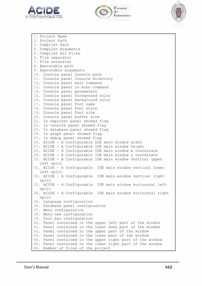
User’s Manual 162
1. Project Name 2. Project Path 3. Compiler Path 4. Compiler Arguments 5. Compiler All Files 6. File separator 7. File extensión 8. Executable path 9. Executable arguments 10. Console panel Console path 11. Console panel Console directory 12. Console panel exit command 13. Console panel is echo command 14. Console panel parameters 15. Console panel foreground color 16. Console panel background color 17. Console panel Font name 18. Console panel Font style 19. Console panel Font size 20. Console panel buffer size 21. Is explorer panel showed flag 22. Is console panel showed flag 23. Is database panel showed flag 24. Is graph panel showed flag 25. Is debug panel showed flag 26. ACIDE - A Configurable IDE main window width 27. ACIDE - A Configurable IDE main window height 28. ACIDE - A Configurable IDE main window x coordinate 29. ACIDE - A Configurable IDE main window y coordinate 30. ACIDE - A Configurable IDE main window vertical upper
left split
31. ACIDE – A Configurable IDE main window vertical lower left split
32. ACIDE – A Configurable IDE main window vertical right split
33. ACIDE – A Configurable IDE main window horizontal left split
34. ACIDE – A Configurable IDE main window horizontal right split
35. Language configuration 36. Database panel configuration 37. Menu configuration 38. Menu new configuration 39. Tool bar configuration 40. Panel contained in the upper left part of the window 41. Panel contained in the lower down part of the window 42. Panel contained in the upper part of the window 43. Panel contained in the lower part of the window 44. Panel contained in the upper right part of the window 45. Panel contained in the lower right part of the window 46. Number of files of the project
User’s Manual 163
The following lines show the properties of the project files. For each file there are
seven lines of text storing the file properties. Therefore, there will be many groups of
seven lines in the configuration file as indicated at line number 34. The properties are
as follows:
Absolute path.
Name.
Parent.
Directory flag.
Compilable flag.
Main flag.
Opened flag.
16.5. CONFIGURATION OF LEXICONS
Lexicons can be configured by manually editing XML files that define them.
A XML file that defines a lexicon begins with the root label:
<acide.configuration.lexicon.AcideLexiconConfiguration>
to reference the class AcideLexiconConfiguration. Inside this root label there are
seven basic tags:
_name: defines the name of the lexicon.
_path: indicates the relative path of this file.
_isCompiledOrInterpreted: a false value indicates that the lexicon is
compiled and true indicates that it is interpreted.
_tokenTypeManager: it is a Manager (explained on Chapter 16.1) of the
types of token there are in the lexicon. It consists of a list of objects
AcideLexiconTokenGroup.
_validExtensionsManager: it is a Manager of valid extensions of files at the
lexicon defined in the XML document. The extensions are String objects.
_delimitersManager: it is a Manager of valid delimiters at the lexicon
defined in the XML document. The delimiters are String objects.
User’s Manual 164
_remarksManager: it is not a common Manager. It defines the symbol to
mark a line as a comment in the lexicon. It has four nested labels:
o _symbol: defines the symbol to use to begin a comment line.
o _isCaseSensitive: defines (true or false value) if it is case sensitive.
o _color: defines color of the comments. It has four nested tags (red,
blue, green, alpha) that define the RGB components and the degree of
opacity of the comments.
o _fontStyle: defines the font style of comments.
16.5.1. TOKENTYPE MANAGER
This label has two nested _list labels. Inside of the most nested there are the
AcideLexiconTokenGroup objects that define the token types in the lexicon. The
AcideLexiconTokenGroup objects have five nested labels:
_name: it is a summary of the properties defined by the remaining labels. It
has the following form:
o Color: [R: _, G: _, B: _], Font Style: __, Case Sensitive: _
o For color will take the values defines in the label _color. In Font Style
appears the name that corresponds to the number defined on the
label _fontStyle. In Case Sensitive value yes appears if the label -
_IsCaseSensitive is true and value not if the label _IsCaseSensitive has
value false.
_color: same structure as explained for _color label above.
_fontStyle: it defines with a number the font style.
_isCaseSensitive: it defines by true or false value if it is case sensitive.
_tokenList: contains a label called _list where appears the list of String
objects which define the tokens with the properties user has described for
this token group. Adding, removing and editing these strings the user will
get the list of tokens.
16.5.2. VALIDEXTENSION MANAGER
As a Manager, it has two nested _list labels. Inside the last the user can find String
objects labels where he can define extensions valid for the lexicon.
User’s Manual 165
16.5.3. DELIMITERS MANAGER
It is a Manager whose list contains String objects. With the strings the user defines
the valid delimiters for the lexicon.
16.6. COMMANDS HISTORY
In ACIDE – A Configurable IDE is possible to configure a commands history so that
when user starts the application already exits this history, similar to when he gets
commands entered earlier in the same run.
The XML file that contains the commands history must be saved in the path
./configuration/console.
The root label of this file is:
<acide.configuration.console.AcideConsoleCommandsConfiguration>
to reference the AcideConsoleCommandsConfiguration class.
Inside this label user has to define another label of Manager type called
_commandsManager.
As usual at Managers, there are two nested _list. Inside the last the user defines by
String labels the commands he wants to introduce in the commands history. The first
command at the list acts like the less recently entered at the console.
User’s Manual 166
17. REGULAR EXPRESSIONS
A regular expression, often called pattern, is an expression that describes a set of
strings without listing their elements. Most formalizations provide the following
constructors: a regular expression is a way of representing regular languages (finite
or infinite) and is constructed using alphabet characters on which the language is
defined. Regular expressions provide a flexible way to search or recognize strings.
17.1. CONSTRUCTION OF REGULAR EXPRESSIONS
Specifically, regular expressions are built using the operators union,
concatenation and Kleene closure.
Alternation: A vertical bar separates alternatives. For example,
“red|brown“joins with red or brown.
Quantification: A quantifier after a character specifies the frequency with
which this can occur. The most common quantifiers +, ? and *:
o +: The plus sign indicates that the preceding character must appear
at least once. For example, hello+ joins hello, helloo, hellooo, etc.
o ?: The question mark indicates that the preceding character can
appear at most once. For example, S?pain joins Spain and pain.
o : The asterisk indicates that the preceding character can appear
zero, one, or more times. For example 10 joins 1, 10, 100, 1000,
etc.
Grouping: Parentheses may be used to define the scope and precedence of
other operators. For example, “(m|h)ouse” is the same as “mouse | house”
and “(in)?sensitive” joins with insensitive and sensitive.
Builders can be freely combined within the same expression, so “H (ae? | ä) del” is
the same as “H (a |ae | ä) del”.
Its most obvious use is to describe a set of strings, which is useful in text editors
and applications for searching and manipulating text.

User’s Manual 167
17.2. DESCRIPTION OF REGULAR EXPRESSIONS
17.2.1. THE DOT “.”
The dot is interpreted by the search engine as “any character”, looking for any
character NOT including line breaks.
The dot is used as follows: If we search “g.t” in the string “gat get got goot” the
search engine will find “gat” “get” “got”. Note that the search engine don’t find “goot”,
this is because the dot represents a single character and only one.
17.2.2. THE BACKSLASH “\”
It is used to “tag” the next character in the search expression so that it acquires a
special meaning or stop having him. The backslash is never used by itself, but in
combination with other characters. Used for example in combination with the point
“\.”, this has not its normal meaning and behaves as a literal character.
In the same way, placing a backslash followed by any of the special characters
discussed below, these do not have special meaning and become literal search
characters.
As mentioned previously, the backslash can also give special meaning to
characters that do not. Below is a list of some of these combinations:
\t: represents a tab.
\r: represents the carriage return or return to top, the place where the line
starts again.
\n: represents the new line character through which a line begins.
Remember that in Windows is needed a combination of \r\n to start a new
line, while Unix uses only \n and classic Mac OS uses only \r.
\a: represents a bell or beep that occurs when you print this character.
\e: represents the Esc or Escape.
\f: represents a page break.
\v: represents a vertical tab.
\x: is used to represent ASCII or ANSII code.
\u: is used to represent UNICODE characters with its code.

User’s Manual 168
\d: represents a digit from 0 to 9.
\w: represents any alphanumeric character.
\s: represents a blank space.
\D: any character other than a digit from 0 to 9.
\W: represents any non-alphanumeric character.
\S: any character other than a blank.
\A: represents the beginning of the string. Not a character but a position.
\Z: represents the end of the string. Not a character but a position.
\b: marks the beginning and end of a word.
\B: marks position between two alphanumeric or non-alphanumeric
characters.
17.2.3. THE BRACKETS “[]”
The function of the brackets in regular expressions is to represent “character
class”, grouping characters into groups or classes. They are useful when is needed to
find one of a group of characters. Within the brackets you can use the “-“ to specify
ranges of characters. Additionally, the metacharacters lose their meaning and become
literal when they are inside the brackets. For example, as mentioned previously, “\d”
is useful to find any character that represents a digit. However, this name does not
include the “.” dividing the decimal part of a number. To search for any character that
represents a digit or a point we can use the regular expression “[\d.]”. As noted above,
within the brackets, the point represents a literal character, not a metacharacter, so it
is not necessary to precede the backslash. The only character that must be preceded
by the backslash inside the brackets is the backslash.
17.2.4. THE BAR “|”
This character is used to indicate one of several options. For example, the regular
expression “a|e” find all “a” or “e” in the text. The regular expression
“East|West|North|South” will find any of the names of the cardinal points. The bar is
commonly used in conjunction with other special characters.

User’s Manual 169
17.2.5. THE DOLLAR SIGN “$”
This character represents the end of the string or the end of the line when using
the multi-line mode. There is not a special character, but a position. Using the regular
expression “\.$” the engine will find all the places where a line ends with a dot, which
is useful for moving between paragraphs.
17.2.6. THE CARET “^”
This character has a dual function, which differs when used alone and when used
in conjunction with other special characters. Firstly its functionality as an individual
character: the character “^” represents the beginning of the chain (in the same way
that the dollar sign “$” represents the end of the string). Therefore, using the regular
expression “^[a-z]” the engine will find all paragraphs beginning with a lowercase
letter. When used in conjunction with the brackets, for example with the form
“[^\w]”, is useful to find any character that is not in the indicated group. The above
expression can found any character that is not alphanumeric or a space, all
punctuation and other special characters.
17.2.7. PARENTHESES “()”
Similarly to the brackets, parentheses are used to group characters. However,
there are several differences between groups established by brackets and groups
established by parentheses:
Special characters keep their meaning within the parentheses.
Groups established by parentheses make a label for the search engine that
can be used later as denoted below.
Used in conjunction with bar “|” enables optional searches. For example, the
regular expression “to (East | West | North | South) of” searches texts giving
instructions through cardinal points, while the regular expression “East |
West | North| South” find “east” in the word “beast”, failing to fulfill this
purpose.
Used in conjunction with other special characters listed below provide
additional functionality.

User’s Manual 170
17.2.8. THE QUESTION MARK “?”
The question mark has several features in regular expressions. The first is to
specify which part of the search is optional. For example, the regular expression
“S?pain” can find both “pain” and “Spain”. In conjunction with parentheses specifies
that a larger set of characters is optional, for example, “Nov(\.|ember|iembre)?” finds
both “Nov.”, “November” and “Noviembre”. Similarly, you can use the question mark
with another meaning. Parentheses define groups “anonymous”, but the question
mark in conjunction with triangular brackets “<>” give name to such groups as
follows: “^(?<Day>\d\d)/(?<Month>\d\d)/(?<Year>\d\d\d\d)$” Whereupon it
specifies to the search engine that the first two digits found will be labeled “Day”, the
second will be labeled “Month” and the last four digits will be labeled “Year”.
17.2.9. THE BRACES “{}”
Usually the braces are literal characters which are used separately in a regular
expression. To be used as metacharacters they have to enclose one or more numbers
separated by commas and to be placed to the right of another regular expression as
follows: “\d{2}”. This expression will find two adjacent digits. Using this formula, the
example “^\d\d/\d\d/\d\d\d\d$” that served to validate a date format will become
to “^\d{2}/\d{2}/\d{4}$” for clarity in reading the expression.
17.2.10. THE ASTERISK “*”
The asterisk is used to find something that is repeated 0 or more times. For
example, using the expression “[a-zA-Z]\d*” will be possible to find both “H” and
“H1”, “H01”, “H100” and “H1000”, a letter followed by a indefinite number of digits.
17.2.11. THE PLUS SIGN “+”
It is used to find a string that is repeated one or more times. The expression “[a-
zA-Z]\d+” will find “H1” but will not find “H”.