aci torsion
DESCRIPTION
concrete torsionTRANSCRIPT

Torsion Design of Structural Concrete Based on ACI 318-05
By Mahmoud E. Kamara, Ph.D., and Basile G. Rabbat, Ph.D., S.E.
PROFESSIONAL DEVELOPMENT SERIES
September 2007

� PDH Special Advertising Section — Portland Cement Association
Torsional moment develops in structural concrete members as a result of asymmetrical loading or member geometry, or as a result of structural fram-ing. For example, spandrel beams built integrally
with the floor slab are subject to torsional moment resulting from the restraining negative bending moment at the exte-rior end of the slab. The restraining moment is proportional to the torsional stiffness of the spandrel beam. In complex structures such as helical stairways, curved beams, and eccen-trically loaded box beams, torsional effects dominate the structural behavior. Torsional moment tends to twist the structural member around its longitudinal axis, inducing shear stresses. However, structural members are rarely subjected to pure torsional moment. In most cases, torsional moments act concurrently with bending moment and shear forces.
During the first half of the twentieth century, structural codes were silent regarding torsion design. Torsion was looked at as a secondary effect that was covered in the factor of safety considered in the design. Demand for more complex struc-tures, improved methods of analysis, new design approaches, and the need for more economical design required a better understanding of the behavior of reinforced concrete members subjected to torsion. In the second half of the twentieth century, research activities helped engineers understand many aspects of behavior of concrete members under torsion.
This article focuses on torsion in solid and hollow closed
sections. Thin, open C- and U-shaped sections subject to torsion suffer distortions (referred to as Vlasov torsion), and are not covered in this article. The procedure presented herein reflects the provisions of the American Concrete Institute’s Building Code Requirements for Structural Concrete (ACI 318-05) (Reference 1) and those of the soon-to-be-published ACI 318-08. All section numbers within this article refer to ACI 318-05. Note that the fourth edition of the American Association of State Highway and Transportation Officials’ Load and Resistance Factor Design (AASHTO LRFD) Bridge Design Specifications prescribes torsion design approaches for structural concrete members slightly different from those of ACI 318.
Equilibrium versus compatibility torsionIt is important for designers to distinguish between
two types of torsions: equilibrium torsion and compatibil-ity torsion (References 2 and 3). Equilibrium torsion occurs when the torsional resistance is required to maintain static equilibrium. For this case, if sufficient torsional resistance is not provided, the structure will become unstable and collapse. External loads have no alternative load path and must be resisted by torsion.
Compatibility torsion develops where redistribution of torsional moments to adjacent members can occur. The term compatibility refers to the compatibility of deformation between
Professional Development Series
Torsion Design of Structural Concrete Based on ACI 318-05 By Mahmoud E. Kamara, Ph.D., and Basile G. Rabbat, Ph.D., S.E.
Continuing EducationThe Professional Development
Series is a unique opportunity to earn continuing education credit by reading specially focused, sponsored articles in Structural Engineer. If you read the following article, display your under-standing of the stated learning objec-tives, and follow the simple instructions, you can fulfill a portion of your continu-ing education requirements at no cost to you. This article also is available online at www.zweigwhite.com/media/pdh/index.asp.
InstructionsFirst, review the learning objec-
tives below, then read the Professional Development Series article. Next, complete the quiz and submit your
answers to the Professional Development Series sponsor. Submittal instruc-tions are provided on the Reporting Form, which follows the quiz and is also available for download at www.zweigwhite.com/media/pdh/index.asp. Your quiz answers will be graded by the Professional Development Series spon-sor. If you answer at least 80 percent of the questions correctly, you will receive a certificate of completion from the Professional Development Series spon-sor within 90 days and will be awarded 1.0 professional development hour (equivalent to 0.1 continuing educa-tion unit in most states). Note: It is the responsibility of the licensee to determine if this method of continuing education meets his or her governing board(s) of registration’s requirements.
Learning ObjectivesThis article discusses torsion in
concrete structures. Upon reading the article and completing the quiz, the reader should be able to understand the behavior and design of struc-tural concrete members subjected to torsion. The article presents the American Concrete Institute’s Building Code (ACI 318-05) design provisions and detailing requirements for torsion design. All referenced items are from ACI 318-05, unless noted otherwise. Also, all notations and definitions in the article are in accordance with Chapter 2 of ACI 318-05.
Professional Development Series SponsorPortland Cement Association
adjacent parts of a structure. As an example, consider a spandrel beam supporting an exte-rior slab. As load on the slab increases, so does the nega-tive slab end moment, which induces torsion in the spandrel beam. The negative slab end moment will be proportional to the torsional stiff-ness of the span-drel beam. When
the magnitude of the torsional moment exceeds the cracking torque, torsional cracks spiral around the member, and the cracked torsional stiffness of the spandrel beam is significantly reduced (Reference 4). As a result, some of the slab negative end moment is redistributed to the slab midspan.
In cases where equilibrium torsion exists or torsional behavior dominates the structural actions, the designer must design for the maximum torsional moments.
Behavior of beams in torsionPrior to cracking, a torsional moment applied to a concrete
member is resisted by internal shear stresses. The largest shear stresses occur in the middle of the outside faces or perimeter of the cross section. Shear stresses lead to diagonal principal tensile and compressive stresses. When the diagonal tension exceeds the tensile strength of the concrete, diagonal crack-ing occurs. It has been observed in experiments on beams subject to torsion that once the crack initiates, it spirals around the perimeter of the member. Simultaneously, the beam torsional stiffness drops significantly. It takes significant twisting before recovering the cracking torque. Upon further torsional loading, excessive twisting deformations lead to spalling of the concrete cover over the transverse reinforce-ment. Hence, transverse reinforcement must be properly anchored with 135-degree hooks.
It has further been observed experimentally that solid and hollow beams of similar external cross section and with similar longitudinal and transverse reinforcement achieve comparable torsional strengths (References 5 and 6). Thus, in a solid beam, part of the concrete core separates from the outer shell (inside the transverse reinforcement) and becomes inefficient. Therefore, when the torsional strength of a beam is reached, a solid section can be represented by a hollow section of the same external dimensions.
Evolution of torsion design provisions The first design provision for torsion appeared in ACI 318-
63. It consisted of one sentence, which prescribed the use of closed stirrups in edge and spandrel beams and one longi-
tudinal bar in each corner of those closed stirrups. Comprehensive design provisions for torsion were introduced in the 1971 code. These design requirements remained essentially unchanged through the 1992 code. These first-generation provisions were semi-empirical and applied only to reinforced, non-prestressed concrete members. The design procedure for torsion was analogous to that for shear. Torsional strength consisted of a contribution from concrete, Tc , and a contribution from stirrups and longi-tudinal reinforcement, Ts, based on a skew bending model.
The design provisions for torsion were completely revised in the 1995 code and remain essentially unchanged since then. The design procedure for solid and hollow members is based on a thin-walled tube, space truss analogy. This unified approach applies equally to non-prestressed and prestressed concrete members.
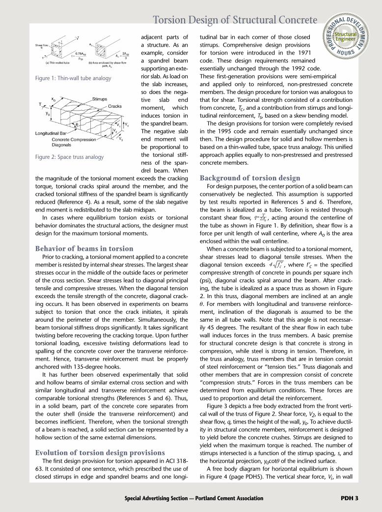
Background of torsion designFor design purposes, the center portion of a solid beam can
conservatively be neglected. This assumption is supported by test results reported in References 5 and 6. Therefore, the beam is idealized as a tube. Torsion is resisted through constant shear flow, T
2Aoq= , acting around the centerline of
the tube as shown in Figure 1. By definition, shear flow is a force per unit length of wall centerline, where Ao is the area enclosed within the wall centerline.
When a concrete beam is subjected to a torsional moment, shear stresses lead to diagonal tensile stresses. When the diagonal tension exceeds 4 fc , where f ′c = the specified compressive strength of concrete in pounds per square inch (psi), diagonal cracks spiral around the beam. After crack-ing, the tube is idealized as a space truss as shown in Figure 2. In this truss, diagonal members are inclined at an angle θ. For members with longitudinal and transverse reinforce-ment, inclination of the diagonals is assumed to be the same in all tube walls. Note that this angle is not necessar-ily 45 degrees. The resultant of the shear flow in each tube wall induces forces in the truss members. A basic premise for structural concrete design is that concrete is strong in compression, while steel is strong in tension. Therefore, in the truss analogy, truss members that are in tension consist of steel reinforcement or “tension ties.” Truss diagonals and other members that are in compression consist of concrete “compression struts.” Forces in the truss members can be determined from equilibrium conditions. These forces are used to proportion and detail the reinforcement.
Figure 3 depicts a free body extracted from the front verti-cal wall of the truss of Figure 2. Shear force, V2, is equal to the shear flow, q, times the height of the wall, yo. To achieve ductil-ity in structural concrete members, reinforcement is designed to yield before the concrete crushes. Stirrups are designed to yield when the maximum torque is reached. The number of stirrups intersected is a function of the stirrup spacing, s, and the horizontal projection, yocotθ of the inclined surface.
A free body diagram for horizontal equilibrium is shown in Figure 4 (page PDH5). The vertical shear force, Vi , in wall
Figure 1: Thin-wall tube analogy
Figure 2: Space truss analogy
Torsion Design of Structural Concrete
Special Advertising Section — Portland Cement Association PDH �

� PDH Special Advertising Section — Portland Cement Association
Torsion Design of Structural Concrete“i” is equal to the product of the shear flow, q, times the length of the wall, yi. Vector Vi can be replaced by two vectors: a diagonal
component, Di, with an inclination θ equal to the angle of the truss diagonals; and a horizontal
component, Ni, centered at the mid height of the wall as shown in the figure.
Torsion can be neglected if the factored torque, Tu, is less than fTcr/4, where
is the cracking torque (Section 11.6.1); f = strength reduc-tion factor for torsion; Acp = area enclosed by outside perim-eter of concrete cross section, including the void of hollow cross-sections; and pcp = outside perimeter of concrete cross-section. The cracking torque corresponds to a principal tensile stress of 4 fc .
Whether a rein-forced concrete member is subject to torsion only, or to flexure combined with shear, the stiffness of that member will decrease after cracking. The reduction in torsional stiffness
after cracking of a member subject to torsion only is much larger than the reduction in flexural stiffness after cracking of a member subject to bending only. If the torsional moment, Tu, in a member cannot be reduced by redistribution of internal forces in the structure (equilibrium torsion), that member must be designed for the full torsional moment, Tu (Section 11.6.2.1). If redistribution of internal forces can occur, as in indeterminate structures (compatibility torsion), the design torque can be reduced. Members subject to compatibility torsion need not be designed for a torque larger than the product of the cracking torque times the strength reduction factor f (which is 0.75 for torsion,). For cases of compatibility torsion where Tu > fTcr, the member can be designed for fTcr only, provided redistribution of internal forces is accounted for in the design of the other members of the structure (Section 11.6.2.2).
Critical sectionIn non-prestressed members, the critical section for torsion
design is at distance d (effective depth) from the face of support. Sections located at a distance less than d from the face of support must be designed for the torque at distance d from the support. Where a cross beam frames into a girder at a distance less than d from the support, a concentrated torque occurs in the girder within distance d. In such cases, the design torque must be taken at the face of support. The same rule applies to prestressed members, except that h/2 replaces d, where h is the overall height of composite section.
Torsional moment strengthThe design torsional strength should be equal to or greater
than the required torsional strength: jTn ≥ Tu. The nominal torsional moment strength in terms of stirrup yield strength is:
where Ao = 0.85Aoh and Aoh = area enclosed by centerline of the outermost closed transverse torsional reinforcement having a yield strength fyt, as illustrated in Figure 5; and θ = angle of compression diagonal, ranges between 30 and 60 degrees. It is suggested in Section 11.6.3.6 to use θ = 45 degrees for non-prestressed members and θ = 37.5 degrees for prestressed members with prestress force greater than 40 percent of tensile strength of the longitudinal reinforcement. To resist torsion, transverse as well as longitudinal reinforce-ment is required. The total area of longitudinal reinforcement Al distributed around the perimeter is computed from:
where At = area of transverse torsional reinforcement at spac-ing s; ph = perimeter of outermost transverse reinforcement; and fy = yield strength of longitudinal reinforcement.
Maximum torsional capacityTo reduce unsightly cracking and prevent crushing of the
concrete compression struts before yielding of the reinforce-ment, Section 11.6.3.1 prescribes an upper limit for the maximum nominal shear stress due to shear and torsion, analogous to that due to shear only. In solid sections, stresses due to shear act over the full width of the section, while stresses due to torsion are assumed resisted by a thin-walled tube. Thus, Section 11.6.3.1 specifies an elliptical interaction between stresses due to shear and those due to torsion for solid sections as follows:
For hollow sections, the interaction is linear and expressed as:
where Vc is the contribution of concrete to shear strength of non-prestressed and prestressed concrete members.
Details of torsional reinforcementLongitudinal and transverse reinforcement are required
to resist torsion. Longitudinal reinforcement may consist of non-prestressed or prestressed reinforcement. Transverse reinforcement may consist of stirrups, welded wire reinforce-ment, or spiral reinforcement. To control widths of diagonal cracks, the design yield strength of longitudinal and trans-verse torsional reinforcement must not exceed 60,000 psi (Section 11.6.3.4).
In the truss analogy illustrated in Figure 2, the diagonal compression strut forces bear against the longitudinal corner
Figure 3: Free body diagram for vertical equilibrium
Tcr 4 fc ( )Acp2
pcp
Tn = cot2AoAt fyt
s
A ( ) ph ( )cot2Ats
fytfy
( )+( ) ( +8 )Vubwd
Vcbwd
Tuph1.7Aoh2 f c
( )2+( )2 ( +8 )Vubwd
Vcbwd
Tuph1.7Aoh2 f c

Special Advertising Section — Portland Cement Association PDH �
Torsion Design of Structural Concretere in forcement . In each wall, the component of the diagonal struts, perpendicular to the longitudinal reinforcement is transferred from the longitudinal reinforcement to the transverse rein-forcement. It has been observed in torsional tests of beams loaded to destruction that as the maximum torque is reached, the concrete cover spalls. The forces in the compres-sion struts outside of the stirrups, for example within the concrete cover, push out the
concrete shell. Based on this observation, Section 11.6.4.2 specifies that the stirrups should be closed, with 135-degree hooks or seismic hooks as defined in Section 21.1. Stirrups with 90-degree hooks become ineffective when the concrete cover spalls. Similarly, lapped U-shaped stirrups have been found to be inadequate for resisting torsion due to lack of bond when the concrete cover spalls. Additionally, for hollow sections, the distance from the centerline of the transverse torsional rein-forcement to the inside face of the wall of the hollow section must not be less than 0.5Aoh/ph (Section 11.6.4.4).
Minimum torsion reinforcementTo ensure ductility of non-prestressed and prestressed
concrete members, minimum reinforcement is specified for flexure (Section 10.5) and for shear (Section 11.5.6). Similarly, minimum transverse and longitudinal reinforce-ment is specified in Section 11.6.5 whenever Tu > fTcr/4. Usually, a member subject to torsion will also be simultane-ously subjected to shear. The minimum area of stirrups for shear and torsion is computed from:
The minimum area of longitudinal reinforcement is computed from:
where At/s (due to torsion only) must not be taken less than 25bw/fyt.
Spacing of torsion reinforcement
Spacing of stirrups must not exceed the smaller of ph/8 and 12 inches. For a square beam subject to torsion, this maximum spac-ing is analogous to a spacing of about d/2 in a beam subject to shear.
The longitudinal reinforcement required for torsion must be distributed around the perimeter of the closed stirrups, at a maximum spacing of 12 inches. In the truss anal-ogy, the compression struts push against the longitudinal reinforcement, which transfers the transverse forces to the stirrups. Thus, the longitudinal bars should be inside the stirrups. There should be at least one longitudinal bar or tendon in each corner of the stirrups to help transmit the forces from the compression struts to the transverse rein-forcement. To avoid buckling of the longitudinal reinforce-ment due to the transverse component of the compression struts, the longitudinal reinforcement must have a diameter not less than 1/24 of the stirrup spacing, but not less than 3/8 of an inch.
Summary of ACI 318-05 Code Design Approach
The following steps summarize the design provisions outlined in Chapter 11 of ACI 318-05 for members subjected to the combined effects of flexure, shear, and torsion. The same provisions appear in ACI 318-08 except that the sections have been renumbered.
Step 1 — Determine the maximum factored torsional moment, Tu , at the critical section of the member from structural analysis of the framing system, based on the appli-cable factored load combination(s).
Step � — Determine whether torsional effects need to be considered by comparing the factored torsional moment Tu to fTcr/4, where Tcr is calculated as follows for non-prestressed members:
for prestressed members:
If Tu < Tcr/4, then torsional effects need not be consid-ered, and the member must be designed for the effects of flexure and shear only (Section 11.6.1). However, if Tu ≥ Tcr/4, the section must be designed for the effects of flexure, shear, and torsion. The following steps apply when torsional effects must be considered.
Step � — Ascertain whether the torsional moment Tu determined in Step 1 can be reduced by redistribution of internal forces after torsional cracking. For members in a statically indeterminate structure where redistribution of forces can occur, the maximum factored torsional moment at the critical section can be reduced to fTcr where Tcr is as computed in Step 2.
Figure 4: Free body diagram for hori-zontal equilibrium
Figure 5: Definition of Aoh
f cTcr = 4 ( )Acp2
Pcp inch-pounds (in.-lb); and
(Av + 2At) = 0.75bwsfyt
50bwsfyt
f c
5 Atfy s
fytfy
f AcpcA ,min = - ( )ph
f cTcr = 4 ( ) 1+ 4
Acp2
Pcp in.-lb.f c
fpc

� PDH Special Advertising Section — Portland Cement Association
Torsion Design of Structural ConcreteIt is important to note that the redistri-
bution of internal forces must be consid-ered in the design of the adjoining members
(Section 11.6.2.2); the reactions from the adjoining members after redistribution must be
transferred to the member that is subjected to the torsional moments.
When fTcr/4 < Tu < fTcr , the section should be designed to resist Tu . For members in which redistribution of the forces is not possible, the maximum factored torsional moment, Tu , at the critical section determined in Step 1 cannot be reduced (Section 11.6.2.1).
Step � — Check adequacy of cross-sectional dimensions (Section 11.6.3) as follows for solid sections:
for hollow sections:
The nominal shear strength provided by the concrete, Vc , can be determined from ACI 318-05 Equation 11-3 for non-prestressed members and Equation 11-9 for prestressed members with an effective prestress force not less than 40 percent of the tensile strength of the flexural reinforcement. The cross-sectional dimensions must be adjusted when the above applicable equation is not satisfied.
Step � — Determine transverse reinforcement required for torsion (Section 11.6.3.6):
where Ao = 0.85Aoh and θ = 45 degrees for non-prestressed members, 37.5 degrees for prestressed members with an effective prestress force not less than 40 percent of the tensile strength of the longitudinal reinforcement. Note that fyt must not exceed 60,000 psi (Section 11.6.3.4). Values of At/s can be determined at various locations along the span, depending on the variation of Tu .
Step � — Determine transverse reinforcement required for shear (Section 11.5.6):
Values of Av/2s can be determined at various locations along the span, depending on the variation of Vu , and, for prestressed members, also depending on the variation of Vc (see Equation 11-9).
Step 7 — Determine the total required transverse rein-forcement per leg and the maximum allowable spacing, considering the most restrictive requirements for shear and torsion (Sections 11.6.3.8, 11.6.5.2, and 11.6.6.1):
where the maximum closed stirrup spacing, s, is the smaller
of ph/8; 12 inches; and d/2 for non-prestressed members, or 3h/4 for prestressed members.
Step 8 — Determine longitudinal reinforcement required for torsion (Sections 11.6.3.7, 11.6.5.3):
where
Step 9 — Combine the longitudinal reinforcement required for torsion with that which is required for flex-ure (Section 11.6.3.8). To achieve a uniform distribution of reinforcement around the perimeter of the section, assign approximately one-quarter of Al to each face. For non-prestressed members, provide an area of steel equal to at least Al/4 on each side face of the section, and add Al/4 to the negative and positive flexural reinforcement at the top and bottom of the section, respectively. For prestressed members, provide additional reinforcing bars with a tensile capacity of Alfy , or use any overcapacity of the tendons to resist some of the axial force Alfy .
Selected References
1) ACI Committee 318, Building Code Requirements for Structural Concrete (ACI 318-05) and Commentary (ACI 318R-05), American Concrete Institute, Farmington Hills, Mich., 2005.
2) Fanella, D. A. and Rabbat, B.G., Design of Concrete Beams for Torsion, Engineering Bulletin EB106.02D, Portland Cement Association, Skokie, Ill., 1997.
3) Kamara, M.E., and Rabbat, B.G., editors, Notes on ACI 318-05 Building Code Requirements for Structural Concrete with Design Applications, Portland Cement Association, Skokie, Ill., EB705, 2005.
4) Lampert, Paul, Post-cracking Stiffness of Reinforced Concrete Beams in Torsion and Bending, ACI Special Publication SP-35, pages 385-433, American Concrete Institute, Farmington Hills, Mich., 1973.
5) Lampert, P., and Thurlimann, B., Torsionsversuch an Stahlbetonbalken (Torsion Tests of Reinforced Concrete Beams), Bericht Nr. 6506-2, 101 pages, Institute of Baustatik, ETH, Zurich, Switzerland (in German), 1968.
6) MacGregor, J. G., and Ghoneim, M. G., “Design for Torsion,” ACI Structural Journal, V. 92, No. 2, pages 211-218, Mar.-Apr. 1995.
Mahmoud E. Kamara, Ph.D., is a senior structural engineer at the Portland Cement Association in Skokie, Ill. He can be reached at [email protected]. Basile G. Rabbat, Ph.D., S.E., is the manager of structural codes at the Portland Cement Association.
( )2+( )2 ( +8 )Vubwd
Vcbwd
Tu ph1.7Aoh2
f c in.-lb; and
( )+( ) ( +8 )Vubwd
Vcbwd
Tuph1.7Aoh2
f c in.-lb.
=Tu
2Ao fyt cotAts
=Vu- Vc2 fytd
Av2s
+Av2s
25bwfyt
Ats in.-lb;
A ( ) ph ( )cot2 A ,minAts
fytfy
5 Atfy s
fytfy
f AcpcA ,min = - ( )ph in.-lb.
Special Advertising Section — Portland Cement Association PDH 7
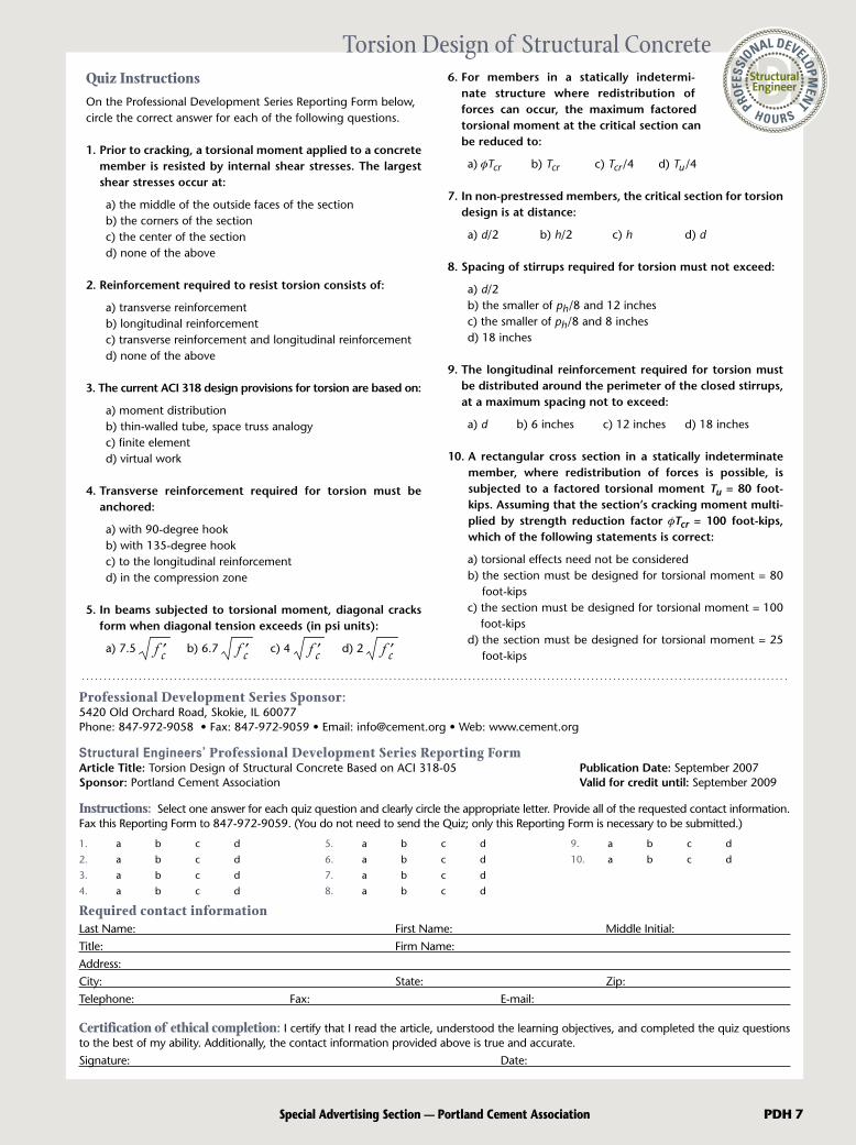
Torsion Design of Structural ConcreteQuiz InstructionsOn the Professional Development Series Reporting Form below, circle the correct answer for each of the following questions.
1. Prior to cracking, a torsional moment applied to a concrete member is resisted by internal shear stresses. The largest shear stresses occur at:
a) the middle of the outside faces of the section b) the corners of the section c) the center of the section d) none of the above
2. Reinforcement required to resist torsion consists of:
a) transverse reinforcement b) longitudinal reinforcement c) transverse reinforcement and longitudinal reinforcement d) none of the above
3. The current ACI 318 design provisions for torsion are based on:
a) moment distribution b) thin-walled tube, space truss analogy c) finite element d) virtual work
4. Transverse reinforcement required for torsion must be anchored:
a) with 90-degree hook b) with 135-degree hook c) to the longitudinal reinforcement d) in the compression zone
5. In beams subjected to torsional moment, diagonal cracks form when diagonal tension exceeds (in psi units):
a) 7.5 f c b) 6.7 f c c) 4 f c d) 2 f c
6. For members in a statically indetermi-nate structure where redistribution of forces can occur, the maximum factored torsional moment at the critical section can be reduced to:
a) fTcr b) Tcr c) Tcr/4 d) Tu/4
7. In non-prestressed members, the critical section for torsion design is at distance:
a) d/2 b) h/2 c) h d) d
8. Spacing of stirrups required for torsion must not exceed:
a) d/2 b) the smaller of ph/8 and 12 inches c) the smaller of ph/8 and 8 inches d) 18 inches
9. The longitudinal reinforcement required for torsion must be distributed around the perimeter of the closed stirrups, at a maximum spacing not to exceed:
a) d b) 6 inches c) 12 inches d) 18 inches
10. A rectangular cross section in a statically indeterminate member, where redistribution of forces is possible, is subjected to a factored torsional moment Tu = 80 foot-kips. Assuming that the section’s cracking moment multi-plied by strength reduction factor fTcr = 100 foot-kips, which of the following statements is correct:
a) torsional effects need not be considered b) the section must be designed for torsional moment = 80
foot-kips c) the section must be designed for torsional moment = 100
foot-kips d) the section must be designed for torsional moment = 25
foot-kips
Professional Development Series Sponsor:5420 Old Orchard Road, Skokie, IL 60077Phone: 847-972-9058 • Fax: 847-972-9059 • Email: [email protected] • Web: www.cement.org
Structural Engineers’ Professional Development Series Reporting FormArticle Title: Torsion Design of Structural Concrete Based on ACI 318-05 Publication Date: September 2007Sponsor: Portland Cement Association Valid for credit until: September 2009
Instructions: Select one answer for each quiz question and clearly circle the appropriate letter. Provide all of the requested contact information. Fax this Reporting Form to 847-972-9059. (You do not need to send the Quiz; only this Reporting Form is necessary to be submitted.)
Required contact informationLast Name: First Name: Middle Initial:Title: Firm Name: Address: City: State: Zip:Telephone: Fax: E-mail:
Certification of ethical completion: I certify that I read the article, understood the learning objectives, and completed the quiz questions to the best of my ability. Additionally, the contact information provided above is true and accurate.Signature: Date:
1. a b c d
2. a b c d
3. a b c d
4. a b c d
5. a b c d
6. a b c d
7. a b c d
8. a b c d
9. a b c d
10. a b c d

0050-06-355
pcaStructurePoint’s suite of productivity tools are so easy to learn and simple to use that you’ll be able to start saving time and money almost immediately. And when you usepcaStructurePoint software, you’re also taking advantage of the Portland Cement Association’s more than 90 years of experience, expertise, and technical support in concretedesign and construction.
Visit pcaStructurePoint.com to download your trial copy of our software products.
For more information on licensing and pricing options please call 847.966.4357 or [email protected].
Analysis, design & investigation of reinforced concrete beams & slab systems
Finite element analysis &design of reinforced, precast,ICF & tilt-up concrete walls
Analysis, design & investigation of reinforced concrete beams & one-way slab systems
Design & investigation of rectangular, round & irregularly shaped concrete column sections
Work quickly. Work simply.
Work accurately.
Finite element analysis & design of reinforced concrete foundations, combined footings or slabs on grade
pcaStructurePoint’s Productivity Suite of powerful software toolsfor reinforced concrete analysis & design
S.E.-StrPt Update Feb07.qxp 12/19/06 1:17 PM Page 1
Enter #129 at gostructural.com/infodirect