accurate and fast testing technique of operational
TRANSCRIPT

Accurate and Fast Testing Technique of
Operational Amplifier DC Offset Voltage
in μV-order by DC-AC Conversion
The 3rd International Test Conference in Asia, 2019
Tokyo Denki Univ., Tokyo, September 4, 2019
Gunma UniversityYuto Sasaki, Kosuke Machida, Riho Aoki, Shogo Katayama
Takayuki Nakatani, Jianlong Wang, Anna Kuwana
Kazumi Hatayama, Haruo Kobayashi
ROHM Co,. Ltd.Keno Sato, Takashi Ishida, Toshiyuki Okamoto
Tamotsu Ichikawa

Purpose
To achieve high accuracy and fast testing of
very small DC voltage with Automatic Test Equipment (ATE)
• Requirements
• μV-order Testing
• Fast Testing
• Proposed Method
FFT-Based DC-AC Conversion
2/33

• Background and Motivation
– Conventional Test Method
– Difficulty for μV-order Testing
• Proposed Method
– FFT-Based DC-AC Conversion
– Challenge for Multi-Site Testing
• Conclusion
Outline
3/33

• Background and Motivation
– Conventional Test Method
– Difficulty for μV-order Testing
• Proposed Method
– FFT-Based DC-AC Conversion
– Challenge for Multi-Site Testing
• Conclusion
Outline
4/33

Background
Sensor
OP-Amp ADCLPF MCU
Illuminance
Humidity Temperature
μV-order offset OP-Amp is a key component of IoT system
IoT Sensor Network
Wi-Fi
5/33
Gyro
Pressure Soil
Accelerator
GeomagneticSonar
Image
Sounds
Flow

Conventional Test Method ( 1 )
[1] James M. Bryant, ”Simple Op Amp Measurement”,
Analog Dialogue, vol.45, pp 21-23 (2011)
Null Method for OP-Amp Test Circuit
6/33

Conventional Test Method ( 2 )
KEYSIGHT 3458A 8 ½ Digit
Usage of High Accuracy Digital Multimeter
7/33

• Background and Motivation
– Conventional Test Method
– Difficulty for μV-order Testing
• Proposed Method
– FFT-Based DC-AC Conversion
– Challenge for Multi-Site Testing
• Conclusion
Outline
8/33

Difficulty for μV-order Testing
Problem
1. Noise at Test Environment
WA Prober
Tester
WA Prober
Tester Noise
Noise Noise
Actual Situation
System noises affect μV-order Testing
9/33
Test Environment

Difficulty for μV-order Testing (Cont’d)
Problem
2. Test Time (Multi-Site)
Single Multi
Unrealistic Situation
10/33

Difficulty for μV-order Testing (Cont’d)
EMF of Metal Film Resistance: 30 μV/℃
Vemf = V1 – V2 = 30 μV * (T1 - T2) ;T1>T2
Problem
3. Electromotive Force (EMF)
Keep temperature difference small enough
Copper
Traces
Resistor
End Caps
J1
Resistor
Film
T1 T2J2 J4J3
V1 V2
V1, V2 : Voltage
T1, T2 : Temperature
J1, J2, J3, J4 : Contact of different metals
Vemf : Difference btw V1 and V2
11/33

Motivation
To Solve Problems
1. Noise at Test Environment
2. Test Time
3. Electromotive Force (EMF)
Testing
Testing method
Temperature difference
To Propose μV-order Test Method for ATE 12/33
NOT affected by system noises
Applicable to multi-site testing
Less than 0.1 ℃ for μV-order testing

Outline
• Background and Motivation
– Conventional Test Method
– Difficulty for μV-order Testing
• Proposed Method
– FFT-Based DC-AC Conversion
– Challenge for Multi-Site Testing
• Conclusion
13/33

Proposed Method
FFT-Based DC-AC Conversion
DC Voltage AC Square Wave
Mag
. [V
rms]
Frequency [Hz]
Fast Fourier Transform
DC Voltage is converted to Fundamental Power Spectrum14/33

FFT-Based DC-AC Conversion (Simulation)
LTspice FFT Condition:
Fs = 409.6 kHz, Fres = 100 Hz, N = 4096, Rectangle Window
DC-AC Conversion Clock: 1 kHz (duty 50 %)
CMOS Switch: Nch FET (2N4393)
DC-AC Conversion Circuit FFT Result
-
+
Single-End
Amplifier
100x
Clock = 1 kHz
FFT16bit
ADC
AC
Amplifier
~ 100x
Sampling Rate
100 kHz
Vin = 1 μV
Measurement as low as 1 nV is possible, based on simulation
15/33 Thanks to FFT, system noises can be ignored
Ignored system noises

FFT-Based DC-AC Conversion (Initial Experiment)
Experiment Environment
Analysis using LabVIEW
DC-AC Conversion
Environment•LabVIEW
•NI USB-6001/6002/6003 (16 bit ADC)
Switch: CMOS Analog SW IC (4053)
16/33

Switching Noise Problem
Initial Circuit
Consideration of Differential Amplifier Usage
Switching Noise
Single-End Amplifier
Monitor
-
+
Clock = 1 kHz
FFT16bit
ADC
AC
Amplifier
~ 100x
Sampling Rate
100 kHz
Vin = 1 μV
Monitor
17/33
Switching
Noise
Single-End Amplifier
100x

Switching Noise Countermeasure
Effect of Switching Noise w/ Countermeasure
Differential Amplifier (Add Dummy Switch)
Improved Circuit
Switching noise is reduced to 1/5
Monitor
-
+
Differential Amplifier
100x
Vin = 1 μV
Clock = 1 kHz
FFT16bit
ADC
AC
Amplifier
~ 100x
Sampling Rate
100 kHz
Monitor
18/33
Switching Noise
Dummy SwitchDifferential Amplifier

Switching Clock Leak Problem
Affect of Switching Clock Leak
Initial Circuit
Switching Noise
1
2
3
4
5
6
7
8
16
15
14
13
12
11
10
9
S2
S3 S1
-+
S1 CTRL
S2 CTRL
S3 CTRL
Clock = 1 kHz
Vin = 1 μVDifferential
Amplifier
100x
4053 CMOS SW
Parasitic capacitance btw Pin and Pin affect switching clock leak
Capacitance bond
Monitor
19/33
Monitor

Switching Clock Leak Countermeasure
Affect of Switching Clock Leak w/ Countermeasure
Improved Circuit
Switching noise is reduced to 1/10
1
2
3
4
5
6
7
8
16
15
14
13
12
11
10
9
S2
S3 S1
-+
S1 CTRL
S2 CTRL
S3 CTRL
Differential
Amplifier
100x
4053 CMOS SW
Switching Noise
Clock = 1 kHz
Monitor
Monitor
20/33
Vin = 1 μV
Use of S3 instead of S1

Measurement with Both Countermeasures
Sampling Rate: 100 kHz, Sample: 10 k, Averaging: 100, Frequency Resolution: 10 Hz
it’s possible to measure as low as 2 μV
EMF countermeasure is essential for further performance
21/33

Electromotive Force (EMF) Countermeasure
EMF Countermeasure
Heatsink
Upside down Switch IC (4053) contact Heatsink via Copper Tape (GND)
Differential Amp
AC Gain Amp
Switch IC (4053) is covered
by StyrofoamStyrofoam Box
Top View
Copper Tape
(GND)
DC-AC
Conversion
22/33

EMF Countermeasure Effectiveness
EMF Countermeasure
Circuit Board
Vin = OPEN CMOS SW
4053
Peripheral
Circuit
Initial Condition (Exposed in atmosphere)
EMF affects output
Monitor
Offset affected EMF is
equivalent to Vin = 1 μV
Improved Condition (Constant Temperature)
CMOS SW
4053
Peripheral
Circuit
Vin = OPEN
Heatsink Copper Tape
(GND)
Heatsink
GND
Styrofoam Box
Monitor
Significant Improvement
It’s possible to measure
as low as Vin = 1 μV
23/33

Power Spectrum with All Countermeasures
Improved Result
Vin = 0 μV
Vin = 1 μV
Sampling Rate: 100 kHz, Sample: 10 k, Averaging: 100, Frequency Resolution: 10 Hz
24/33it’s possible to measure 1 μV
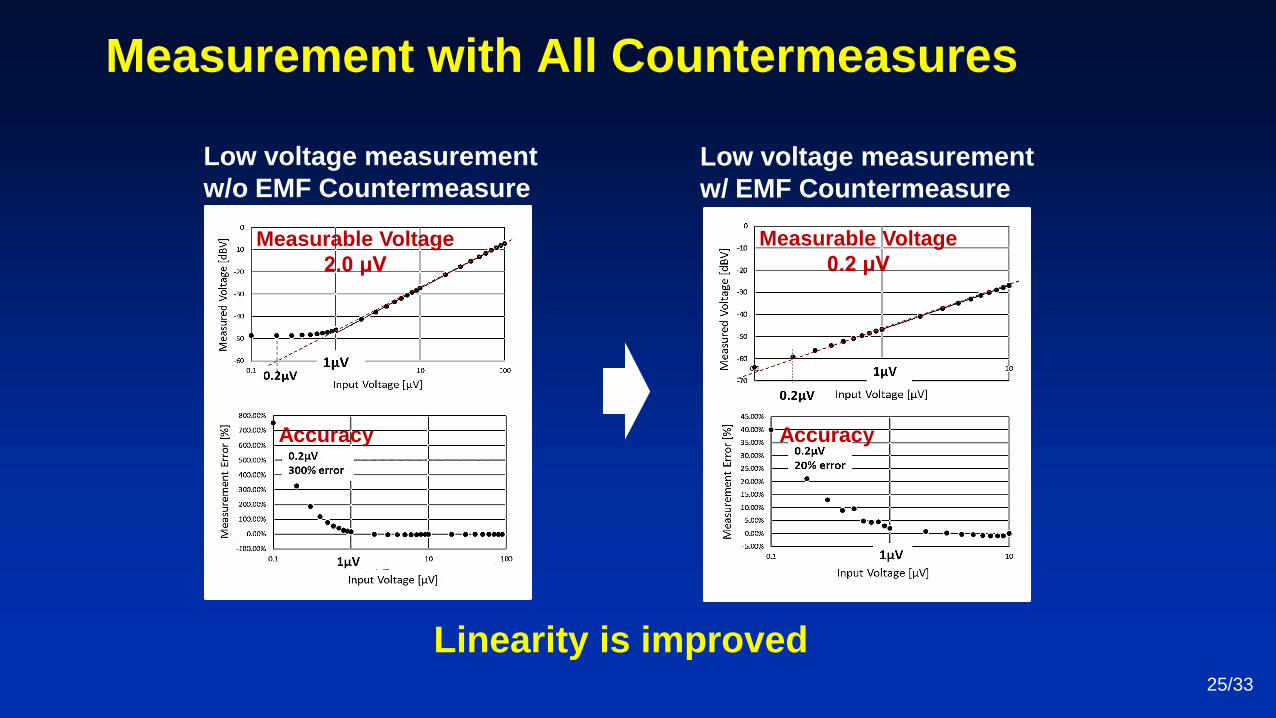
Measurement with All Countermeasures
Linearity is improved
Low voltage measurement
w/o EMF Countermeasure
Measurable Voltage
2.0 μV
Accuracy
Low voltage measurement
w/ EMF Countermeasure
Measurable Voltage
0.2 μV
Accuracy
25/33

Accuracy 1μV + 10 %Accuracy 1μV + 3 % Accuracy 1μV + 1 %
Dependent on the number of averages 26/33
100ksps,10kpoint, Average 100x 100ksps,10kpoint, Average 10x 100ksps,10kpoint, Average 1x
Variation and Repeatability of Measurement
100ksps,10kpoint, Average 100x 100ksps,10kpoint, Average 10x 100ksps,10kpoint, Average 1x

Outline
• Background and Motivation
– Conventional Test Method
– Difficulty for μV-order Testing
• Proposed Method
– FFT-Based DC-AC Conversion
– Challenge for Multi-Site Testing
• Conclusion
27/33

FFT-Based DC-AC Conversion for Multi-Site Testing
FFT16bit
ADC
Adder Circuit
-+
AC
Amplifier
~ 100x
DC-AC
Conversion
DC-AC
Conversion
DC-AC
Conversion
Ch1
Ch2
Chn
Expected FFT Result
Frequency [Hz]
Pow
er
[dB
]
Multi-site testing is possible
Ch1 Ch2 Chn
28/33
Configuration & Operation

Differential Amplifier
AC Gain AmplifierClock Gen
DC-AC Conversion
Experiment Environment for Multi-Site Testing
Upside down Switch IC (4053) contact Heatsink via Copper Tape (GND)
Heatsink
Copper Tape
(GND)
DC-AC Conversion Part
29/33
Four-Site case

Verification with Spectrum Measurement
Four-Site Testing Measured Spectrum
Vin1 = 0 V
Vin2 = 0 V
Vin3 = 0 V
Vin4 = 0 V
Residual Spectrum (Input = 0V)
Ch1 =1.0 kHz, Ch2 = 1.2 kHz, Ch3 = 1.4 kHz, Ch4 = 1.6 kHz
Vin1 = 1 μV
Vin2 = 2 μV
Vin3 = 3 μV
Vin4 = 4 μV
4ch入力印加スペクトラムVoltage input Spectrum
Sampling Rate: 100 kHz , Sample: 10k, Averaging: 100, Frequency Resolution: 10 Hz
30/33Multi-site testing is applicable

Verification with Linearity Measurement
Four-Site Testing
Four-site measurement as low as 0.2 μV is possible31/33
Ch2
1.01 kHz
Ch3
1.02 kHz
Ch1
1.00 kHz
Ch4
1.03 kHz
Sampling Frequency Interval: 0.01 kHz
Ch2
1.1 kHz
Ch3
1.2 kHz
Ch1
1.00 kHz
Ch4
1.3 kHz
Sampling Frequency Interval: 0.1 kHz

• Background and Motivation
– Conventional Test Method
– Difficulty for μV-order Testing
• Proposed Method
– An FFT-Based DC-AC Conversion
– Challenge for Multi-Site Testing
• Conclusion
Outline
32/33

Conclusion
Solved Problems
Proposed FFT-based DC-AC conversion is applicable
for μV-order test using ATE
1. Noise at Test Environment
2. Test Time
3. Electromotive force (EMF)
Testing is NOT affected by system noises
Testing method is applicable to multi-site testing
Keep temperature difference less than 0.1 ℃ for μV-order testing
33/33

Q&A
• Is the EMF Seebeck effect?
– Yes.
• How about a throughput of the test? It seems to need a time
for steady temperature of changed DUT against EMF.
– No problem because temperature of test environment is
under control. In addition, temperature difference is no
effect except between regsistors in a DC-AC conversion
circuit.
34/32