accumulator ring design for the nsns project/67531/metadc675087/m2/1/high... · accumulator ring...
TRANSCRIPT

1997 P a r t i c l e Acce lera tor Canada, May 12-16, 1997
Conf., Vancouver, B.C. ,
ACCUMULATOR RING DESIGN FOR THE NSNS PROJECT * W.T. Weng, J. Alessi, J. Beebe-Wang, M. Blaskiewicz, L. Blumberg, M. Brennan, C. Gardner,
Y.Y. Lee, A.U. Luccio, H. Ludewig, D. Maletic, D. Raparia, A. Ruggiero, S.Y. Zhang AGS Department, Brookhaven National Laboratory, Upton, NY 11973.
Abstract
The goal of the proposed National Spallation Neutron Source (NSNS) is to provide a short pulse proton beam of about 0 . 5 ~ s with average beam power of 1MW. To achieve such purpose, a proton storage ring operated at 6OHz with 1 x 10¹⁴ protons per pulse at lGeV is required. The Accu- mulatorRing (AR) receives lmsec long H' beam bunches of 28mA from a lGeV linac. Scope and design perfor- mance goals of the AR are presented, other possible tech- nological choices and design options considered, but not adopted, are also briefly reviewed.
1 INTRODUCTION
The Oak Ridge National Laboratory is leading a con- ceptual design for a next generation pulsed spallation neutron source, the National Spallation Neutron Source (NSNS) [l]. There are three major accelerator systems included in Brookhaven's area of responsibility. First is the High Energy Beam Transport ("EF3T) system [2]. Sec- ondly, the Accumulator Ring (AR) system and thirdly, the Ring to Target Beam Transport (RTBT) system [3]. This paper describes the design of the AR itself whose magnet and tunnel layout is shown in Fig. 1.
The proton Accumulator Ring is one of the major sys- tems in the design of the NSNS. The primary function of the AR is to take the 1 GeV H' beam of about 1 msec length from the linac and convert it into a 0 . 5 ~ s beam through a stripping foil in about one thousand tums. The final beam should have 1 . 0 ~ 1014 protons per pulse, resulting in 1MW design average beam power at 60Hz repetition rate. Pro- visions have been reserved for a future upgrade to 2MW beam power by doubling the stored current to 2 . 0 ~ 10" proton per pulse without changes in both the magnet and vacuum system.
One of the major performance requirements is to keep the average uncontrolled particle loss during the accumula- tion time to less than 2 . 0 ~ per pulse. The reason of this stringent requirement is to keep the residual radiation to such a level that the hands-on maintenance is possible except for a few localized areas, such as: injection, extrac- tion and collimation. To achieve this goal, special care have been exercised in the H' stripping, the RF stacking, and the collimator design.
This paper describes the final product of the inten- sive R&D efforts in the past two years. During that pe-
Research on rhe NSNS is sponsored by the Division of Material Sci- ences. U.S. Department of Energy, under contract number DE-ACOS- 960R22464 with Lockheed Manin Energy Research Corporation for Oak Ridge National Laboratory.
..n- . . - S I I . .
ARC - A S CELL
ElVED
Figure 1: Layout of the accumulator ring.
r id , we have studied many possible technologies and de- sign choices. Some of the considerations and rationals of choices are given here for comparison.
a Accumulator Ring vs Rapid Cycling Synchmmn. The AR option is chosen for better injection efficiency, no eddy current effects and shorter beam-in-ring time to avoid coherent instabilities.
b. One vs Two Ring Tunnels. Separate tunnels for future upgrade is chosen for its simplicity in mechanical de- sign, reliability in future operation, accessibility for maintenance, and low initial capital investment. Both the performance goal and specific design of the second ring can be decided at the time of upgrade.
c. FODO vs Triplet Lam'ce. A FODO lattice is cho- sen for its smoothness in betatron function varia- tion around the ring. Such a property will minimize the possible envelope oscillation for beam with large space charge tune shift.
d. Normal vs Isochronous Lattice. Our choice is for a normal lattice, even if, at a first look, isochronous lat- tice may offer the advantage of constant longitudinal extend of the injected beam. However, it hurts in many other ways. For example, the higher order chromatic effects in lattice, reduction in dynamic aperture, and the reduction in Landau damping for transverse insta- bilities.
e. Single, Dual, Bam'er Cavity RF Systems. The dual harmonic RF system is chosen for its advantage in
higher bunching factor and established performances. The barrier cavity system holds promises of keeping the beam within the confine of the RF bucket and leav- ing the gap clean. However, it requires more RF sta- tions and the beam dynamics related to beam loading and coherent instabilities is not well-understood.
2 LATTICE, H- INJECTION AND RF STACKING
The accumulator ring of the National Spallation Neutron Source (NSNS) will have a four-fold symmemc lattice.
accommodate the long straight sections re- njection system, the extraction system, the
$UT c%@i~s, and the beam scraping system. The straight d o n s $ill be dispersion free, which is desirable, espe-
the RF cavities and the injection system. The 1 provide ease of betatron tuning and flexibility
of operation. Unlike lattices-of lower symmetry, a lattice of four-fold symmetry will asstqe that there are no danger- ous betatron structure resonan05 other than for the integer tune. Details of lattice design is given in ref. [4]. Lattice functions and other salient performauce and design param- eters of the accumulator ring are summarized in Table 1.
<$
Table 1: NSNS Accumulatorring Beam Average Power Kinetic Energy Average Current Repetition Rate Ion Source Peak Current Linac Peak Current Beam Duty Cycle Linac Pulse Length Beam Loss (ControllecLWncontrolled) Number of Turns Injected Revolution Period Revolution Frequency Circumference Space-Charge Tune-Shift Bunching Factor (Dual RF Systems) Number of Protons/Ring Beam Emittance (Transverse, nom.) Tunes vzlvY Pm,*WY) Dispersion X,(max/min) Transition Energy T~ RF Voltage (13* Harmonic) RF Voltage (2nd Harmonic) R F bucket Beam Emittance (Longitudinal) Beam Gap (injection) Injected Pulse Len,& Vacuum
m e t e r s 1.0 Mw 1.0 Gev 1.0 mA 60 Hz 35 mA 27.7 mA 6.18 % 1.03 msec e 21 0.02 % 1225 0.841 3 psec 1.1886 MHz 220.688 m < 0.1 0.405 1 . 0 4 ~ 1014 217 n m - m 5.82 I 5.80 19.2 / 19.2 m 4.UO.O m 4.93 40 kV 20 kV
10 eV-sec 295 nsec 5 4 6 nsec
17 eV-sec
10-9 TOR
The most demanding system in the design of the 1MW short pulse spallation neutron source is the H' multi-turn injection into the storage ring. For the NSNS accumulator
ring, a carbon foil of 400pgkm' is assumed. The stripping efficiency for 1GeV incident H- beam is about 99.8%. The temperature rise for the 1MW design is estimated to be about 3200OC. In addition, it has been found that 151
a. Stripping losses in passage of the H' beam through the B-3kG field in a DC bump dipole magnet up- stream of the stripper foil are negIigible.
of the incident H- beam will emerge as Ho from a 400pglcm' carbon stripper foil and must be disposed of in an external dump.
c. Field ionization of the H'component in the B-2.41 kG field of a quadrupole downstream of the foil will lead to negligible uncontrolled losses.
d. Fractional losses from nuclear non-elastic interactions in the foil as low as 1 .26~ can be realized with rapidly (exponentially) collapsing injection bumps and "smoke-ring" injection scheme which result in very small multiple foil traversals of < Nt >=2.43 traversaldinjected proton.
e. Multipole Coulomb and nuclear elastic scatter- ing fractional losses out of a ring acceptance of Az,,-330nmm-mrad for the above injection condi- tions are 1 . 3 5 ~ well below our loss criterion of
With the small area stripper foil (8mm H x 4mm V) used for the above estimates, 22% of the in- cident H' beam misses the foil and will be deflected by a magnet to an external dump.
b. A fraction f ( H " ) =8.19x
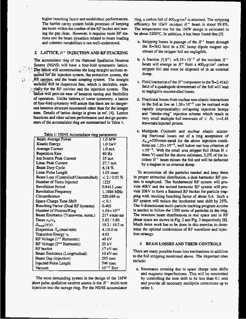
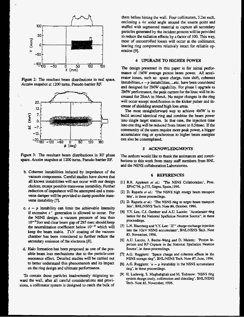
To accumulate all the particles needed and keep them in proper azimuthal distribution, a dual harmonic RF sys- tem is employed. The fundamental RF system will pro- vide 40kV and the second harmonic RF system will pro- vide 20kV to form a flattened RF bucket for particle trap- ping with resulting bunching factor of about 0.4. Such a RF system will reduce the incoherent tune shift by 25%. The Cdimensional multi-particle uacking program Accsim is needed to follow the 1200 turns of particles in the ring. The resultant beam distributions in real space and in RF phase space are shown in Fig. 2 and Fig. 3 respectively [6]. Much more work has to be done in this exercise to deter- mine the optimal combination of RF waveform and injec- tion strategy.
3 BEAM LOSSES AND THEIR CONTROLS
There are'many possible beam loss mechanisms in addition to the foil stripping mentioned above. The important ones include:
a. Resonance crossing due to space charge tune shifts and magnetic imperfections. This will be minimized by controlling the tune shift to be less than 0.1 unit and provide all necessary multipole corrections up to order 3.
100 ,I, t I 1
50 n E
W € 0 >
-50
Figure 2 The resultant beam distributions in real space. Accsim snapshot at 1200 turns. Pseudo barrier RF.
20. 13.
-*%O -120 -60 0 60 120 180 9 (de4
Figure 3: The resultant beam distributions in RF phase space. Accsim snapshot at 1200 turns. Pseudo barrier RE
b. Coherent instabilities induced by impedance of the
C.
d.
vacuum components. Careful studies have shown that all known instabilities will not occur with our design choices, except possible transverse instability. Further reduction of impedance will be attempted and a trans- verse damper will be provided to damp possible trans- verse instability [7l.
e - p instability can limit the achievable intensity if excessive e‘ generation is allowed to occur. For the NSNS design, a vacuum pressure of less than 10’gTOrr and clear beam gap of 295 nsec should keep the neutralization coefficient below which will keep the beam stable. T i N coating of the vacuum chamber has been considered to further reduce the secondary emission of the electrons 181.
Halo formation has been proposed as one of the pos- sible beam loss mechanisms due to the particle-core resonance effect. Detailed studies will be carried out to better understand this phenomenon and its impact on the ring design and ultimate performance.
To contain those particles inadvertently migrating to- ward the wall, after all careful considerations and provi- sions, a collimator system is designed to catch the bulk of
them before hitting the wail. Four collimators, 3.2m each, enclosing a 4n solid angle around the source point and stuffed with segmented material to capture all secondary particles generated by the incident protons will be provided to reduce the radiation effects by a factor of 100. This way, most of uncontrolled losses will occur at the collimator, leaving ring components relatively intact for reliable op- eration 191.
4 UPGRADE TO HIGHER POWER
The design presented in this paper is for initial perfor- mance of 1MW average proton beam power. All accel- erator issues, such as: space charge, tune shift, coherent instabilities, e - p instabilities, ... etc. have been considered and designed for 2MW capability. For phase I upgrade to 2MW performance, the peak current for the linac will be in- creased for 28mA to 56mA. No major changes in the ring will occur except modification in the kicker pulser and in- crease of shielding around high loss areas.
The most straightfornard way to achieve 4MW is to build second identical ring and combine the beam power into single target station. In that case, the injection time kto one ring will be reduced from lmsec to 0.5msec. If the community of the users require more peak power, a bigger accumulator ring or synchrotron to higher beam energies can also be contemplated.
.-
5 ACKNOWLEDGMENTS
The authors would like to thank the assistances and contri- butions to this work from many staff members from BNL and the NSNS collaboration Laboratories.
6 REFERENCES [ll BR. Appleton et al.: ’The NSNS Collaboration’, Proc.
EpAC’96, p.575, Sitges, Spain,1996. [Z] D. Raparia er aL: ’The NSNS high energy beam transport
line’, in these proceedings. [3] D. Raparia et al.: ’The NSNS ring to target beam transport
line’, BNUNSNS Tech. Note #6, October, 1996. [41 Y.Y. Lee, CJ. Gardner and k U . Luccio: ’Accelerator ring
lattice for the National Spallation Neutron Source”, in these proceedings.
[SI L.N. Biumberg and Y.Y. Lee: ’H’ charge exchange injection into the lGeV NSNS accumulator’, BNLfNSNS Tech. Note #3, November, 1996.
[6] A.U. Luccio, J. Beebe-Wang and D. Maletic: ’Proton In- jection and RF Capture in the National Spallation Neutron Source’, in these proceedings.
[71 A.G. Ruggiero: ‘Space charge and coherent effects in the NSNS storage ring”, BNUNSNS Tech. Note #7. June, 1996.
181 A.G. Ruggiero: ‘e - p instability in the NSNS accumulator ring’, in these proceedings.
[9] H. Ludewig, S. Mughabghab and M. Todosow: ’NSNS ring system design study, collimation and shielding’, BNIfNSNS Tech. Note #5, November, 1996.
This report was prepared as an account of work sponsored by an agency of the United States Government. Neither the United States Government nor any agency thereof, nor any of their employees, makes any warranty, express or implied, or assumes any legal liability or responsibility for the accuracy, completeness, or use- fulness of any information, apparatus. product, or process disclosed, or represents that its use would not infringe privately owned rights. Reference herein to any spe- cific commercial product, process, or ~ M c e by trade name, trademark, manufac- turer, or otherwise dots not necessarily constitute or imply its endorsement, recom- menhtion, or favoring by the United States Government or any agency thereof. The views and opinions of authors expressed herein do not necessarily state or reflect those of the United States Government or any agency thereof.
- Portions of this document may be iUegible in electronit imllge products. Images are produced fipm the best available original document.