access system centum series user manual - verilink · access system centum series user manual iii...
TRANSCRIPT

Access System Centum SeriesUser Manual
Access System 100 Single Port CSU/DSUAccess System 150 Drop-and-Insert Single Port CSU/DSUAccess System 200 Dual Port CSU/DSU
Verilink Corporation145 Baytech Drive
San Jose, California 95134
Part Number 896-502379-001-AMarch 1995
Important Notice
VERILINK CORPORATION DISTRIBUTES THIS REFERENCE “AS IS” WITHOUT WARRANTY OF ANY KIND, EITHER LIMITED OR IMPLIED. Verilink Corporation reserves the right to revise this publication from time to time without notice. Some states or jurisdictions do not allow disclaimer of express oimplied warranties in certain transactions; therefore, this statement may not apply to you.
Copyright 1995 Verilink Corporation. All rights reserved.
Your right to copy this manual is limited by copyright law. Making copies of this reference, oany part thereof, without prior written authorization from Verilink Corporation is prohibited by law and constitutes a punishable violation of the law
ii Access System Centum Series User Manual
r
r

ped
is
r
or
Unpacking
This equipment is normally shipped in cardboard cartons with foam inserts to protect the units from shock and vibration during shipment. Upon arrival of the equipment, inspect the condition of the boxes and compare all items to the packing list. Notify Verilink and the carrier immediately if there are any damages or shortages.
Store the cartons and packing material in case the unit has to be shipat a later date.
������������������������������������������������������������������������������������������
WARNING
The following rules should always be followed when connecting telephone equipment and/or wiring:
1. Never install telephone wiring during a lightning storm.
2. Never install the telephone jacks in wet locations unless the jack specifically designed for wet locations.
3. Never touch uninsulated telephone wires or terminals unless the telephone line has been disconnected at the network interface.
4. Use caution when installing or modifying telephone lines.
������������������������������������������������������������������������������������������
Verilink reserves the right to incorporate product enhancements and/ochange product specifications at any time and without notice.
Warranty
All Verilink equipment is covered by a 5-year new product warranty. Fadditional information, call 1.800.VERILINK.
NOTE
Access System Centum Series User Manualiii
les
be
les,
FCC Information
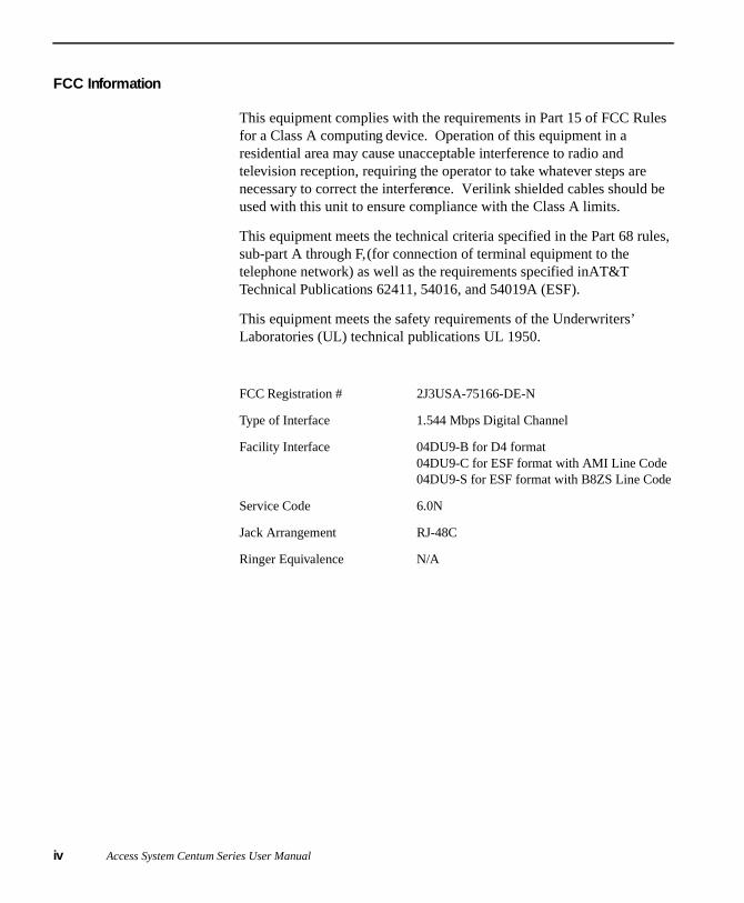
This equipment complies with the requirements in Part 15 of FCC Rufor a Class A computing device. Operation of this equipment in a residential area may cause unacceptable interference to radio and television reception, requiring the operator to take whatever steps arenecessary to correct the interference. Verilink shielded cables shouldused with this unit to ensure compliance with the Class A limits.
This equipment meets the technical criteria specified in the Part 68 rusub-part A through F, (for connection of terminal equipment to the telephone network) as well as the requirements specified in AT&T Technical Publications 62411, 54016, and 54019A (ESF).
This equipment meets the safety requirements of the Underwriters’ Laboratories (UL) technical publications UL 1950.
FCC Registration # 2J3USA-75166-DE-N
Type of Interface 1.544 Mbps Digital Channel
Facility Interface 04DU9-B for D4 format04DU9-C for ESF format with AMI Line Code04DU9-S for ESF format with B8ZS Line Code
Service Code 6.0N
Jack Arrangement RJ-48C
Ringer Equivalence N/A
iv Access System Centum Series User Manual

h o
he
8C
ou
d d.
ng ct e.
ent,
ill
FCC User Requirements
The following instructions are provided to ensure that you comply withthe Federal Communications Commission (FCC) Rules, Part 68:
1. All direct connections to the T1 digital lines must be made througstandard plugs and jacks furnished by the telephone company. nconnections can be made to party lines or coin lines. Before connecting your unit, you must do the following:
a. Tell your local telephone company that you have an FCC registered device that you wish to connect to the company’s lines. Provide the 14-digit FCC registration number listed on tlabel. The telephone company will also need to know the facility interface code (04DU9-B) and service code (6.0N) in order to connect the necessary service.
b. Inform the telephone company that you wish to use the RJ-4jack arrangement.
c. After the telephone company has installed the RJ-48C jack, ymay connect the CSU with the appropriate cable.
2. If the unit appears to be malfunctioning, it should be disconnectefrom the telephone line until the source of the problem is confirmeIf the unit needs repair, it should not be reconnected until after therepair is completed.
3. The CSU has been designed to prevent harm to the DDS or T1 network. IF the telephone company determines that it is exceeditolerance parameters, they are permitted to temporarily disconneservice. When possible, the customer will be given advance notic
4. Under FCC Rules, no customer is authorized to repair the equipmregardless of its warranty status.
5. If the telephone company alters the equipment in a manner that waffect its usage, advance notice must be given to prevent serviceinterruption.
Normally, Verilink CSU equipment will be used to interface either FCCregistered or grandfathered digital terminal equipment to the digital service channel. If the equipment to be connected is not of this type,institutional procedures provide that an affidavit be supplied to the
Access System Centum Series User Manual v

t 68
telephone company. This affidavit must state that the system will be operated only by trained individuals and that the signal power at the telephone company interface will not exceed the limits set forth in Parof the FCC’s Rules and Regulations.
vi Access System Centum Series User Manual
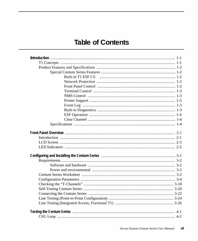
Table of Contents
... 1-2.. 1-2-2
1-21-2-3-3
1-31-3-31-41-4
. 1-4
2-1
1
. 3-2. 3-2.. 3-2.. 3-43-183-203-22
-243-26
4-1
Introduction ................................................................................................................................ 1-1T1 Concepts ...................................................................................................................... 1-1Product Features and Specifications ..............................................................................
Special Centum Series Features ..........................................................................Built-in T1 ESF CS .............................................................................. 1Network Protection .................................................................................Front Panel Control ................................................................................Terminal Control .................................................................................... 1NMS Control .......................................................................................... 1Printer Support ........................................................................................Event Log ...............................................................................................Built-in Diagnostics ................................................................................ 1ESF Operation ........................................................................................Clear Channel .........................................................................................
Specifications .......................................................................................................
Front Panel Overview .................................................................................................................Introduction ...................................................................................................................... 2-1LCD Screen ...................................................................................................................... 2-3LED Indicators ................................................................................................................. 2-5
Configuring and Installing the Centum Series ............................................................................ 3-Requirements .................................................................................................................... 3-2
Software and hardware ........................................................................................Power and environmental ....................................................................................
Centum Series Worksheet ..............................................................................................Configuration Parameters ...............................................................................................Checking the “T-Channels” ............................................................................................Self-Testing Centum Series ............................................................................................Connecting the Centum Series .......................................................................................Line Testing (Point-to-Point Configuration) .................................................................. 3Line Testing (Integrated Access, Fractional T1) ............................................................
Testing the Centum Series .........................................................................................................CSU Loop ......................................................................................................................... 4-2
Access System Centum Series User Manual vii

.4-5
44-
5-1.. 55-15-2
. 5-3
6-1
6-3. 6. 6-46-6
. 6-
. 6-96-116-12
6-16-1866-20
A-1. A-1A-1A-3A-4
-1
Payload BERT .................................................................................................................4-3CSU Loop with BERT .....................................................................................................Payload Loop .................................................................................................................... 4-6Line Loop ......................................................................................................................... 4-7DSX-1 Loop ..................................................................................................................... 4-9Serial Port Loop .............................................................................................................-10Serial Port BERT ............................................................................................................12
Other Features ...........................................................................................................................Alarms and Statistics ......................................................................................................-1
Alarm Definitions .................................................................................................ESF Statistics Definitions .....................................................................................
Alarms/Statistics Menu ...................................................................................................Utilities ............................................................................................................................. 5-5Events ............................................................................................................................... 5-6Event Printing ................................................................................................................... 5-7
Auxiliary Ports ...........................................................................................................................Cabling ............................................................................................................................. 6-2
Auxiliary ports ......................................................................................................Modular Adapters ............................................................................................................-4
Rear panel views ..................................................................................................Terminal Configuration ....................................................................................................Terminal Operation .........................................................................................................8Configuration Menus .......................................................................................................Serial Port Diagnostics ...................................................................................................Link Alarms and Statistics .............................................................................................ESF Registers .................................................................................................................6-13Event Log ....................................................................................................................... 6-15Utilities ........................................................................................................................... 6-16Printer Configuration ......................................................................................................7Printer Port Flow Control ...............................................................................................Printer Operation ............................................................................................................-19Link Alarms and Statistics .............................................................................................
SNMP Management ...................................................................................................................Connecting the Centum Series .......................................................................................
Option #1 .............................................................................................................Option #2 .............................................................................................................
Compiling the Centum Series MIB .................................................................................
Standard Cabling for User Ports ................................................................................................. B
viii Access System Centum Series User Manual

B-1
B-3
-1
C-2C-2C-3C-5
Network Interface and DSX-1 Port .................................................................................V.35 Serial Port ............................................................................................................... B-2RS-442A Serial Port ........................................................................................................
Special Serial Port Cabling ........................................................................................................ CExternal Timing ...............................................................................................................C-1Cables for External Timing .............................................................................................
V.35 Serial Port Cabling ......................................................................................RS-422A Serial Port Cabling ...............................................................................
Cables for Internal/External Timing ................................................................................
Access System Centum Series User Manualix

x Access System Centum Series User Manual

List of Figures
....2-1....2-1....2-2..... 2-4...3-22...3-22...3-23.... 4... 4......... 4.. 4-13... 6-4.....6-4.....6-5.....6-5... A-2... A-2...A-3.. B-1.. B-2. C-2. C-3. C-6. C-7
Figur e2-1 Front Panel: Access System 100 (AS100) Single Port CSU/DSU ...........................Figur e2-2 Front Panel: Access System 150 (AS150) Drop-and-Insert Single Port CSU/DSU Figur e2-3 Front Panel: Access System 200 (AS200) Dual Port CSU/DSU .............................Figur e2-4 Basic Centum Series Menu Tree .............................................................................Figur e3-1 Rear Panel of Access System 100 (V.35 version) ...................................................Figur e3-2 Rear Panel of Access System 150 (V.35 version) ...................................................Figur e3-3 Rear Panel of Access System 200 (V.35 version) ...................................................Figur e4-1 Payload BERT diagram ............................................................................................-4Figur e4-2 CSU Loop with BERT ...............................................................................................-5Figur e4-3 Payload Loop diagram ............................................................................................... 4-6Figur e4-4 Line Loop diagram ...................................................................................................... 4-8Figur e4-5 DSX-1 Loop diagram ................................................................................................4-9Figur e4-6 Serial Port Loop diagram ..........................................................................................-11Figur e4-7 Serial Port BERT and Loop diagram ........................................................................Figur e6-1 6-Pin Modular Adapter Pin Assignments ..................................................................Figur e6-2 Rear Panel of Access System 100 (V.35 version) ...................................................Figur e6-3 Rear Panel of Access System 150 (V.35 version) ...................................................Figur e6-4 Rear Panel of Access System 200 (V.35 version) ...................................................Figur eA-1 SNMP Manager access with a terminal server .........................................................Figur eA-2 SNMP Manager access with a router ........................................................................Figur eA-3 SNMP Manager access via direct or dial-up connection ..........................................Figur eB-1 Network Interface and DSX-1 Port (RJ-48) ..............................................................Figur eB-2 V.35 Serial Port Pin Assignments (M-series, 34-pin connector) ...............................Figur eC-1 V.35 Serial Port #1 Cabling for External Timing .......................................................Figur eC-2 RS-422A Serial Port #1 Cabling for External TIming ...............................................Figur eC-3 V.35 Serial Port #1 Cabling for Internal/External Timing .........................................Figur eC-4 RS-422A Serial Port #1 Cabling for External TIming ...............................................
Access System Centum Series User Manual xi

xii Access System Centum Series User Manual

Chapter
SU
s s, ess
the
tors as is ,
1 Introduction
Verilink’s Access System Centum Series consists of the following three models:
■ Access System 100 Single Port CSU/DSU (AS100)
■ Access System 150 Drop-and-Insert Single Port CSU/DSU (AS150)
■ Access System 200 Dual Port CSU/DSU (AS200)
Verilink’s Centum Series units integrate the capabilities of a T1 ESF C(Channel Service Unit) and DSU (Data Service Unit) in a single unit.
Engineered with either a V.35 or RS-449 serial port, each unit providehigh bandwidth for LANs, image transmission, mainframe file transferand other high-speed, synchronous applications. Additionally, the AccSystem 150 has a DSX-1 port to handle voice transmissions for drop-and-insert applications.
T1 Concepts
A T1 digital transmission facility carries twenty-four 64 kbps DS-0 channels, for a total of 1.536 Mbps (plus 8 kbps overhead to achieve well-known 1.544 Mbps). These DS-0s can be demultiplexed by the Centum Series, and a group of DS-0s can be assigned to the connecon the equipment to transport information. In some cases, the user haccess to the full 64 kbps per channel while, in other cases, the limit 56 kbps per channel. A detailed explanation is provided in Chapter 3Configuring and Installing the Centum Series.
The T1 facility itself can be a physical point-to-point circuit with all 24 DS-0s going from one site to another. The facility can also be an “Integrated Access” that uses a Central Office DACS and one or moreFractional T1 (FT1) links. This is a physical multipoint facility with logical point-to-point links formed by groups of DS-0s.
Access System Centum Series User Manual1-1

el e s one s
s .
rt
Product Features and Specifications
This section explains product features and specifications.
Special Centum Series Features
The Centum Series has a number of special features.
Built-in T1 ESF CSU
Interfacing to T1 or Fractional T1 services requires a T1 CSU (ChannService Unit). The Centum Series includes a built-in T1 ESF CSU asstandard equipment. The superior ESF (Extended Superframe) CSUincludes provisions for continuous performance monitoring by both thuser and the telephone company central office. ESF provides a 4 kbplink control channel (transparent to user data) which allows the telephcompany to monitor the local loop, transmit and receive test messageand retrieve performance data, all without interrupting normal operations.
Network Protection
The Centum Series provides complete electrical protection for the network by automatically inserting pulses into the transmitted signal arequired to meet the bit density formula specified in AT&T Pub 62411
Front Panel Control
The Centum Series is easy to use. Configuration and testing are accomplished with a few buttons. Status is shown on a 32-character liquid crystal display (LCD) screen and 10 front-panel indicators. TheLCD screen serves as a “window” that can be moved vertically. The indicators are separated in NI (Network Interface) and serial (DTE) pogroups.
1-2 Access System Centum Series User Manual

The an
er-
e he eeds
e
and
such s, a nter nt
nt
B,
Terminal Control
All Centum Series features can be accessed via an external terminal.terminal’s CRT allows displays that are much more comprehensive thpossible via the front panel LCD. The user-supplied terminal can be selected from a wide variety of standard offerings or can be a PC withterminal emulation software.
NMS Control
Configuration, dialing, and testing can also be controlled through a ussupplied PC using the optional Verilink SNMP-based network management software. Most DOS-based PC devices can serve as thNMS (Network Management System) console. The console port on trear panel of the Centum Series, an RS-232C connector, supports spof 1200, 2400, 4800, and 9600 bps. A password routine prevents unauthorized access to the NMS console screens.
Printer Support
The Centum Series includes a port for serial printer support. Real-timreports of all system events are automatically sent out this port. In addition, the front panel or an externally attached terminal can commprintouts of configuration, alarms, and ESF statistics.
Event Log
The Centum Series constantly monitors for the occurrence of events, as alarms, test commands, and system resets. When an event occurdescription with a time and date stamp is immediately sent out the priport. In addition, the Centum Series maintains a log of the most recesixteen events and that log can be accessed by either the front panelcontrols and LCD panel or an externally attached terminal.
Built-in Diagnostics
Verilink’s Centum Series includes extensive capabilities to help pinpoinetwork problems without the need for external test equipment. Diagnostics include local and remote Serial Port digital loopbacks, LLRLB, and payload NI loopbacks.
Access System Centum Series User Manual1-3

),
l as unit
p, ata, th
)
g
The Centum Series also includes a built-in bit error rate tester (BERTeliminating the need for external test equipment. The built-in tester transmits a 511-bit pseudo random test pattern. The Centum Series records errors received, seconds in test, and error-free seconds.
Alarm conditions are displayed on the front panel LCD screen as welon the console’s Alarms/Statistics screen. Front panel LEDs indicate and control signal status.
ESF Operation
Centum Series Extended SuperFrame (ESF) operation allows the telephone company central office to continuously monitor the local looto transmit and receive test messages, and to retrieve performance dwithout interrupting normal operations. The unit is compatible with boAT&T 54016 and ANSI T1.403 specifications.
Clear Channel
The Centum Series provides clear channel signalling with B8ZS line coding (in installations where it is supported by the Telco central officeor alternate channel assignment.
Specifications Product specifications for the Centum Series are listed on the followinpage.
1-4 Access System Centum Series User Manual

AS100 AS150 AS200
✔ ✔ ✔✔
✔
56/64 kbps where N = 1 to 24E Synchronous CCITT V.35, EIA RS-422A/530, or A RS-422A/449 with optional adapter
male 34-pin “M-series”, 25-pin “D”, or 37-pin “D” (with optional adapter)
44 Mbpsolar B8ZS/AMI and ESF/D4
male 8-position RJ-48C
ESF/D4 compatibility per AT&T Tech Pubs 62411, 54019, and ANSI T1.40344 Mbps ± 50 bps, bipolar B8ZS or AMI5, 15, 22.5 dB
male 8-position RJ-48Crnalquency locked to NI (Repeater)quency locked to synchronous Serial Port #1quency locked to DSX-1 Portl drive to 6000 feet
al Digital Loopbackmote Digital Loopback (V.54)al CSU Loopback, LLB, RLB, Payload Loopbackwork Interface and Serial Port with bidirectional testing, ctable patterns of “511”, 2047, “1 in 8”, “2 of 16”, and “All Ones”
sity, Loop, BPV, Alarmsity, Loop, BPV, Alarm, Loop, DCD, Loop, DCD
character Liquid Crystal Display (LCD) with front panel buttonsCII terminalrm printer
W x 1.75” H x 10” Dounds (maximum)letop or Rack130 Vac, 57-63 Hz40 degrees C, 90% humidity (non-condensing)
Access System Centum Series User Manual1-5

1-6 Access System Centum Series User Manual

Chapter
ach. of p to t are
2 Front Panel Overview
Introduction
The front panel LCD screen displays two rows of sixteen characters eMenu parameters are presented individually. The buttons to the right the LCD screen scroll data vertically through the screen, displaying utwo parameters at a time. There are also up to 10 LED indicators thaused to display the status of various Centum Series conditions.
Figure 2-1 Front Panel: Access System 100 (AS100) Single PorCSU/DSU
Figure 2-2 Front Panel: Access System 150 (AS150) Drop-and-Insert Single Port CSU/DSU
UP and DOWN arrow buttons — to move to a fieldSELECT button — to choose a parameter or activate a function
END button — to return to next higher menu grouping
LCD screenLED indicators LED indicators
Access System Centum Series User Manual2-1

on,
Figure 2-3 Front Panel: Access System 200 (AS200) Dual Port CSU/DSU
There are two UP/DOWN (arrow) buttons, a SELECT button, and an END button. The basic operating procedures are simple.
1. To select a menu, use the UP and DOWN buttons to move to the desired field.
2. Then, SELECT to choose the submenu.
3. To choose from a particular set of parameters or activate a functiuse the SELECT key. Use END to return to the next higher menu grouping.
UP/DOWN (Arrow) Buttons. These buttons are used to move the display window vertically within a menu grouping. The UP button moves the display window up (backwards). The DOWN button moves the display window down (forward) to the next menu entry.
SELECT .Used to choose a submenu, choose a parameter activate afunction.
END. Used to return to the previous menu.
2-2 Access System Centum Series User Manual

s.
LCD Scree
The LCD screen is limited to two lines of 16 characters each.
The displayed menus include the Main Menu, which is sub-divided into the following five (5) menus: Configuration , Diagnostics, Alarms & Statistics, Event Log, and Utilities . Each sub-menu is further broken down into sub-level menus. Menu examples are shown below. Subsequent chapters give detailed information regarding these menu
Main Menu HH:MM
_Configuration
NI Configuration
Framing: _ESF
Port 1 Diag.
Local Loop: _On
Access System Centum Series User Manual2-3

2-4
Figure
2-4B
asic Centum
Series M
enu Tree
Utilities
SetTime & Date
EditUnit ID
Clear BRAM
Display S/WRevision Level
ConfigureAuxiliary Ports
Acce
ss Syste
m C
en
tum
Se
ries U
ser M
an
ua
l
Configuration
Main Menu
Alarms / Stats Event LogDiagnostics
Entry #1
Entry #2
Entry #3
Entry #16
Clear Log
NI AlarmsNI & DSX-1
Loops & BERT
Serial Port #1Loops & BERT
NIConfiguration
MicroConnecT1Timing
Serial
Display DS-0Assignments
PrintConfiguration
Interfaces
DSX-1Configuration
ESF Statistics
Print Alarms
Print Statistics
DSX-1 Alarms
Serial Port #2Loops & BERT

ate eas l
n
the
LED Indicators
There are up to ten LED indicators on the front panel. The actual quantity differs with the Centum Series model. They are used to indicthe status of various alarm and call conditions. They monitor three arof Centum Series operation: DSX-1, Network Interface (NI) and SeriaChannels.
DEN (Network Interface). Indicates that the Network Interface is forcing the required number of transmitted “ones” to satisfy the T1 network requirements. This could be a result of improper configuratioor failure of the customer’s attached Serial port equipment and will result in data corruption.
AL (DSX-1 Port). ON when receive alarm condition (Red, Yellow, etc.) is detected on the DSX-1 Port.
LP (DSX-1 Port & Network Interface). ON when either the Network Interface or the DSX-1 Port is in a loopback state.
BPV (Network Interface) ON when Bipolar Violations are being received from the network. Can also indicated a very weak or overly strong signal.
AL (Network Interface). ON when receive alarm condition exists (Red, Yellow, etc.)
TST (Serial Port Channel 1). Indicates the status of the BERT test if in progress. Will be ON only if the test results are good.
LP (Serial Port Channel 1). ON when a loop condition exists in the serial port either at the local or remote end.
DCD (Serial Port Channel 1) ON when the state of the Data Carrier Detect (or equivalent) lead being transmitted to the DTE connected toserial port is ON or HIGH .
TST (Serial Port Channel 2). Indicates the status of the BERT test if in progress. Will be ON only if the test results are good.
LP (Serial Port Channel 2). ON when a loop condition exists in the serial port either at the local or remote end.
Access System Centum Series User Manual2-5

the
DCD (Serial Port Channel 2) ON when the state of the Data Carrier Detect (or equivalent) lead being transmitted to the DTE connected toserial port is ON or HIGH .2-6 Access System Centum Series User Manual

Chapter
is
t.
3 Configuring and Installing the Centum Series
������������������������������������������������������������������������������������������������������������������������������������������������������������������������������������WARNING
The following rules should always be followed when connecting telephone equipment and/or wiring:
1. Never install telephone wiring during a lightning storm.
2. Never install the telephone jacks in wet locations unless the jack specifically designed for wet locations.
3. Never touch insulated telephone wires or terminals unless the telephone line has been disconnected at the network interface.
4. Use caution when installing or modifying telephone lines.
������������������������������������������������������������������������������������������
Centum Series units should not be connected to the network until after ithas been completely configured and has successfully passed self tes
NOTE
Access System Centum Series User Manual3-1

Configuring and Installing the Centum Series
tall me al
d be
Requirements
Listed below are the requirements for operating Centum Series units.
Software anhardware
Each Centum Series product is a self-contained unit that can be configured with no additional software or hardware.
This chapter describes the steps necessary to configure, test, and insCentum Series using the front panel buttons and LCD panel. The sasteps can be more easily performed using a customer-supplied externterminal (or PC with terminal emulation software). See Chapte r6, Auxiliary Ports, page 6-8.
Power and environmental
Centum Series uses 110-120 VAC, 60 Hz, at 0.25 amps.
Centum Series does not require a conditioned environment but shouloperated in areas with adequate ventilation.
Centum Series Workshee
3-2 Access System Centum Series User Manual

Centum Series Worksheet
Access System Centum Series User Manual3-3

Ce
ntu
m S
erie
s Worksh
ee
t
Acce
ss Syste
m C
en
tum
Se
ries U
ser M
an
ua
l3-4
Definitions
erial ort 2 DSX-1
Not Used
21 27 27
1
2
2
3
3
3
ce
4
5
6
7
8
9
10
11
12
Serial Port #1
Data Rate:
First DS-0:
Alt/Consecutive:
CD Handling:
Data Norm/Inv:
Clock Norm/Inv:
Clocks:
Remote Loop:
13
14
14
15
16
17
18
19
Serial Port #2
Data Rate:
First DS-0:
Alt/Consecutive:
CD Handling:
Data Norm/Inv:
Clock Norm/Inv:
Clocks:
Remote Loop:
20
21
21
22
23
24
25
26
DSX-1 Interface
Framing:
Line Code:
Distance:
DSX-1 CFA:
27
28
29
30
T-Channel
T-Channel Number
Serial Port 1
SP
DS0-1
DS0-2
DS0-3
DS0-4
DS0-5
DS0-6
DS0-7
DS0-8
DS0-9
DS0-10
DS0-11
DS0-12
DS0-13
DS0-14
DS0-15
DS0-16
DS0-17
DS0-18
DS0-19
DS0-20
DS0-21
DS0-22
DS0-23
DS0-24
14
Centum Series Worksheet

ing
e
the in
ut
et. the
Configuration Parameters
Configuration Parameters
Proper configuration of the Centum Series requires information regardthe network itself and the manner in which the network will be used. Most of this information is readily available from the network supplier although some user decisions must be made from within thelimitations of the network.
This manual includes a configuration worksheet on page 3-2 to aid thuser in configuring the Centum Series. Verilink recommends that the master worksheet be photocopied and that copies be used to record actual information for Centum Series units. By using the information this chapter, one worksheet should be completed for each unit in the network. After completing all worksheets for all units, this chapter should again be used to actually configure the units.
Note that the Centum Series can remain unpowered indefinitely witholosing the configuration parameters.
Plug in the Centum Series and confirm that the LCD panel displays:
If necessary, press the UP or DOWN arrow buttons until the panel displaysthe above information. Now, refer to a photocopied configuration sheThe item numbers below correlate to the reference numbers circled onsheet.
1. Model number Administration information indicating specific Centum Series model being configured.
2. Company name and location. Administrative information determined by customer.
Main Menu HH:MM
_Configuration
Access System Centum Series User Manual3-5

Configuring and Installing the Centum Series
k
3. T-Carrier ID, Local Circuit ID, and Billing Number. Administrative information obtained from the network supplier
4. NI Framing. This information must be obtained from the networksupplier. Repeatedly SELECT to choose between D4 and ESF.
5. NI Line Code. This information must be obtained from the networsupplier. Repeatedly SELECT to choose between AMI and B8ZS.
6. NI LBO. Should be set to 0 dB unless the network supplier specifically requests otherwise. If requested, repeatedly SELECT to choose 0, 7.5, 15, or 22 dB.
Configuration
_NI Interface
SELECT todisplay:
Configuration
Framing:_XX
SELECT todisplay:
NI Configuration
Line Code:_XXX
DOWN todisplay:
NI Configuration
LBO..:_X dB
DOWN todisplay:
3-6 Access System Centum Series User Manual

Configuration Parameters
ork
rm”
7. Network Diagnostics. This entry determines the Centum Series’ability to respond to diagnostic commands received from the netwsupplier. Repeatedly SELECT to choose between Yes and No.
User equipment must always respond to network-generated diagnostic commands. Select Yes unless the commands are to be passed to another T1 device that will respond.
8. NI Density. This information must be obtained from the network supplier. Repeatedly SELECT to choose Clear or 62411. A Clear network imposes no “ones density” requirements on the user. A 62411 network complies with AT&T Technical Reference #62411 and limits Centum Series transmission to no more than fifteen consecutive zeroes.
If the Line Code entry (item #5, above) is B8ZS, choose Clear. If the Line Code entry is AMI, choose 62411.
9. NI CFA. Repeated SELECT to choose between Yes and No.
Yes causes Centum Series to discard data and send a “yellow alaif it is in a “red alarm” condition for three seconds.
NI Configuration
NTWK Diag.: XXX
DOWN todisplay:
NI Configuration
Density: XXXX
DOWN todisplay:
NI Configuration
NI CFA:_XXX
DOWN todisplay:
Access System Centum Series User Manual3-7

Configuring and Installing the Centum Series
tion
no SF
n
Yes MUST be chosen if the network supplier is a common carrier,such as a telephone company. If the network is private, the selecis a user option.
10. ESF Reporting Format. This entry describes the types of ESF network commands that the Centum Series will respond to. It hasmeaning for D4 networks: see Framing (item #4, above). With Enetworks, this information must be obtained from the network supplier.
Repeatedly SELECT to choose between AT&T Technical Reference54016 and ANSI specification T1.403.
11. Clear Registers. Repeatedly SELECT to choose between Yes and No. Yes is the recommended choice.
When commanded by the network supplier, Centum Series will transmit stored error information to the supplier.
A Yes entry will cause Centum Series to clear all error counts whethe unit is powered down and back up again.
A No entry will allow potentially invalid registers in preparation fortransmission to the network supplier.
NI Configuration
ESF Frmt:_XXX
DOWN todisplay:
NI Configuration
Clear Regs:_XXX
DOWN todisplay:
3-8 Access System Centum Series User Manual

Configuration Parameters
if
12. Timing Source. Repeatedly SELECT to choose NI , Port 1, Int , or DSX-1.
In an Integrated Access, Fractional T1 environment, ALL units must use NI timing.
In a point-to-point configuration, one unit must use NI timing and the other unit must use something else. This “something else” is nearly always Int (Internal) but some user configurations require Port 1 or DSX-1 timing. Contact the Technical Assistance Center assistance is needed.
Configuration
_NI Interface
to display:
NI Configuration
_Timing Source
DOWN todisplay:
NI Configuration
_Timing Source
to display:
Access System Centum Series User Manual3-9

Configuring and Installing the Centum Series
0
the te.
Steps 13 through 19 apply to Serial Port #1 while the identical Steps2through 26 apply to Serial Port #2.
13. Serial Port #1 Data Rate. [20. Serial Port #2 Data Rate]
In an Integrated Access, Fractional T1 environment, this selection MUST be coordinated with the network supplier.
Before entering a value, the user must first determine if each DS0will carry 56 kbps or 64 kbps user data and must then determine correct quantity of DS0s necessary to achieve the desired data ra
See Density (item #8, above). If the NI is Clear, the 56/64 decision is completely user optional and 64Kbps is recommended to obtain maximum data transfer efficiency in the network.
NOTE
Main Menu HH:MM
_Configuration
Main Menu,/DOWN to
display:
Configuration
_Serial Port #1 (or 2)
LECT andUP/DOWNto display:
Serial Port #1 (or 2)
_XXXK (XDS0)
SELECT todisplay:
NOTE
3-10 Access System Centum Series User Manual

Configuration Parameters
es
tisfy to
e
el ct
m
If the NI is not Clear, steps must be taken to ensure the proper “ondensity” in the data presented to the network. If this is not done, Centum Series may occasionally damage user data in order to sanetwork requirements. There are three methods that can be usedensure ones density in the data:
• Limit the user data to 56 kbps per DS0. Centum Series will usthe remaining 8 kbps (in each DS0) to provide the required density.
• Allow 64 kbps user data in each DS0 and use alternate DS0s. Keep the intervening DS0s idle to provide the density. See Alt/Consec below (items #14 and #21). This method wastes significant bandwidth and should only be used when absolutelynecessary.
• Allow 64 kbps user data in each DS0 when the user’s protocolprovides the required density. See Data Norm/Inv below (item s#16 and #23).
When the 56/64 decision has been made, repeatedly SELECT until the desired data rate is displayed on the left side of the LCD panAND the correct DS0 quantity is displayed on the right side. SeleN/U if the Serial Port will not be used.
CAUTIONIn some cases, the same data rate can be achieved with two different DS0 quantities, one with 56 kbps DS0s and the other with 64 kbps DS0s.
14. Serial Port #1 DS0 assignments. [21. Serial Port #2 DS0 assignments]
This selection determines which specific DS0s within the T1 streawill support the Serial Port.
!
Serial Port #1 (or 2)
First DS0: XX
DOWN todisplay:
Access System Centum Series User Manual3-11

Configuring and Installing the Centum Series
d
ered ot
a
if 5,
r
In an Integrated Access, Fractional T1 environment, this selection MUST be coordinated with the network supplier.
The First DS0 is the lowest numbered DS0 of the quantity indicatein Data Rate (items #13 and #20, above). Repeatedly SELECT until the desired First DS0 appears in the display. The remaining DS0srequired to support the desired data rate are the next higher numbcontiguous or alternate DS0s except that the string of DS0s cann“wrap” from #24 to #1.
Repeatedly SELECT to choose either Consecutive or Alternate. If Consecutive is chosen, the DS0s assigned to this serial port will becontiguous string beginning with the First DS0.
If Alternate is chosen, Centum Series will insert an idle DS0 immediately after each one required for user data. For example, the first DS0 is #1 and four alternate DS0s are selected, #1, #3, #and #7 will carry user data while #2, #4, #6, and #8 will be idle.
When this selection is made, place checkmarks in the appropriate“T-Channel Definitions” boxes to simplify recordkeeping. Don’t forget to account for 56 kbps vs. 64 kbps DS0s.
15. Serial Port #1 CD handling.[23. Serial Port #2 CD handling]
Centum Series presents a DCE interface to the attached customeequipment. Carrier Detect (CD) can be
• permanently On
NOTE
Serial Port #1 (or 2)
XXXXXXX DS0s
DOWN todisplay:
Serial Port #1 (or 2)
CD..: XX
DOWN todisplay:
3-12 Access System Centum Series User Manual

Configuration Parameters
T1
e
vert
• permanently Off , or
• Switched (normally On, turns Off upon network carrier failure).
Switched is the recommended mode of operation unless the customer DTE requires otherwise. Repeatedly SELECT to choose On, Off , or Switched.
16. Serial Port #1 Data Normal/Inverted. [23. Serial Port #2 Data Normal/Inverted]
Repeatedly SELECT to choose between Normal and Inverted.
Choose Normal if any of the following are true:
• Density (item #8, above) is Clear.
• Data Rate (items #13 and #20, above) uses 56 kbps per DS0
• Alt/Consec (items #14 and #21, above) is Alternate
If none of the above conditions apply, consider the following:
Some user protocols, such as SDLC and HDLC, have a “zeroes density” characteristic that, when inverted, results in the required“ones density”. If the attached DTE uses one of these protocols AND also inverts the data, choose Normal and confirm that the mated serial port (at the “other end” of the circuit) is configured thsame.
If the attached DTE uses one of these protocols and does NOT inthe data, choose Inverted and confirm that the mated serial port (at the “other end” of the circuit) is configured the same.
Serial Port #1 (or 2)
Data..: XXX
DOWN todisplay:
Access System Centum Series User Manual3-13

Configuring and Installing the Centum Series
e).
s
oth
NO OTHER CONDITIONS ARE VALID. Please refer to discussion under Serial Port Data Rate (items #13 and #20, abov
17. Serial Port #1 Clock Normal/Inverted.[24. Serial Port #2 Clock Normal/Inverted]
Repeatedly SELECT to choose Normal or Inverted. Initially choose Normal. If frequent errors occur at this serial port, try Inverted and check performance.
Normally, the down-going clock edge is in the middle of each bit. This is required by networks. Some DTEs, particularly with high-speed V.35 configurations and/or lengthy cables, place the rising edge in the middle of each bit. Inverted will correct this condition to satisfy the network.
18. Serial Port #1 Clock Handling[25. Serial Port #2 Clock Handling]
Repeatedly SELECT to choose Internal , External, or Int/Ext .
External is not available for Serial Port #2.
Internal is the normal setting and should always be chosen unlesthere is specific reason to do otherwise. At the serial interface, Centum Series will provide both TX-clock and RX-clock to the customer DTE.
External should be used with Serial Port #1 if the attached user equipment is DCE, rather than DTE. Centum Series will accept bTX-clock and RX-clock from the customer DCE. This setting
Serial Port #1 (or 2)
Clock..: XXXX
DOWN todisplay:
Serial Port #1 (or 2)
Clocks: XXXX XXX
DOWN todisplay:
NOTE
3-14 Access System Centum Series User Manual

Configuration Parameters
n.
is
m
is ll
d
requires special user cabling and a very specific DCE configuratioPlease refer to Appendi xC, Special Serial Port Cabling for more information.
Int/Ext should be used for Serial Port #1 if the attached user DTEsubstantially far away from Centum Series and/or if Serial Port #1 is to be used as the system’s master clock. See Timing Source (ite#12, above).
Int/Ext should be used for Serial Port #2 if the attached user DTEsubstantially far away from the Centum unit. The Centum unit wiprovide RX-clock to the attached DTE and will accept TX-clock from the DTE.
The Int/Ext setting requires a special DTE requires a special DTEconfiguration or a modified cable. Please refer to Appen d ixC, Special Serial Port Cabling for more information.
Important Notes:
a. If Int/Ext timing has been selected for Serial Port #1 becauseSerial Port #1 is to be used as the system’s master clock (seeitem #12, above), the recommendation in Appendi xC must be followed.
b. If excessive DTE cable distance is the only concern, consider the following:
• Clocking problems appear as periodic (predictable) error bursts.
• Internal Serial Port timing should first be attempted with a normal DTE configuration and a standard cable.
• If clocking problems occur, they can frequently be correcteby using clock inversion (items #17 and #24, above) and retaining the normal DTE configuration and the standard cable.
Access System Centum Series User Manual3-15

Configuring and Installing the Centum Series
of the
• Int/Ext Serial Port timing with the recommendations in Appendix C need be used only if the above efforts fail.
19. Serial Port #1 Remote Loop Enable/Disable.[26. Serial Port #2 Remote Loop Enable/Disable]
Repeatedly SELECT to choose between Enabled and Disabled.
When Enabled, this Serial Port channel will respond to receipt of a remote digital loop command arriving from the Serial Port channelthe mated Centum Series unit. Enabled is recommended unlessuser has specific reason to do otherwise.
When Disabled, this Serial Port channel will not respond to receipt of a remote digital loop command.
Serial Port #1 (or 2)
Rem Loop:_Enabled
DOWN todisplay:
Main Menu HH:MM
_Configuration
Main Menu,/DOWN to
display:
Configuration
_DSX-1 Interface
LECT andUP/DOWNto display:
DSX-1 Config.
Framing:_XXX
SELECT todisplay:
3-16 Access System Centum Series User Manual

Configuration Parameters
d
ary ed).
to
d to ted
l
ed
s
20. DSX-1 port framing.
Repeatedly SELECT to choose the framing provided by the attachePBX: ESF or D4. Choose N/U if a PBX will not be used.
Refer to item #4, earlier. If the NI framing is ESF, the DSX-1 framing can be either ESF or D4 (the unit will provide the necessconversion). If, however, the NI framing is D4, the DSX-1 framingshould also be D4 (conversion from ESF to D4 is not recommend
All DS0s that have not been assigned to Serial Port #1 are given the DSX-1 port by default (unless N/U is selected for DSX-1 framing). If the PBX will use some, but not all, of those DS0s, theappropriate DS0s should be idled by the PBX. The user is advisemark the Worksheet in such a way that PBX idle can be differentiafrom Centum Series idle.
When this selection is made, place checkmarks in the “T-ChanneDefinitions” boxes to simplify recordkeeping.
21. DSX-1 line code.
Repeatedly SELECT to choose the line code provided by the attachPBX: B8ZS or AMI .
Refer to item #5, earlier. If the NI line code is B8ZS, the DSX-1 line code can be either B8ZS or AMI (the Centum Series unit will provide the necessary conversion). If, however, the NI line code iAMI, the DSX-1 framing should also be AMI (conversion from B8ZS to AMI is not recommended).
DSX-1 Config.
Line Code:_XXXX
DOWN todisplay:
DSX-1 Config.
Distance:_XXXft.
DOWN todisplay:
Access System Centum Series User Manual3-17

Configuring and Installing the Centum Series
the
22. PBX distance.
Repeatedly SELECT to choose a distance figure that most closely approximates the cable length from the DSX-1 port to the PBX.
23. DSX-1 CFA.
Repeatedly SELECT to choose No or Yes.
Yes causes the Centum Series unit to pass “red alarm” signals to PBX for appropriate action.
Refer to NI CFA , item #9, earlier.
If NI CFA is Yes, choose DSX-1 CFA No.
If NI CFA is No and the network is provided by a common carrier,such as a telephone company, choose DSX-1 CFA Yes. Ensure that the attached PBX will react to a three-second “red alarm” by discarding data and sending a “yellow alarm”.
If NI CFA is No and the network is private, the selection is a user option.
DSX-1 Config.
DSX-1 CFA:_XX
DOWN todisplay:
3-18 Access System Centum Series User Manual

Checking the “T-Channels”
e 1”
Checking the “T-Channels”
Repeatedly depress UP or DOWN while comparing Centum Series displaywith the checkmarks in the worksheet T-Channel Definitions, columns#14 and 27.
Note that “Idle” refers to channels that have been configured as “Not Used” in the Centum Series. In some cases, typically involving Fractional T1, a portion of the DS0s assigned to the DSX-1 port will bforced to “idle” by the PBX; these channels will be displayed as “DSX-
Main Menu HH:MM
_Configuration
Main Menu,/DOWN to
display:
Configuration
_NI Interface
SELECTto display:
Configuration
_DS0 Assignments
DOWN asrequired to
display:
Channel Mode
_01: XXXX
SELECTto display:
Access System Centum Series User Manual3-19

Configuring and Installing the Centum Series
um
channels by the Centum Series. The user is advised to mark the Worksheet in such a way that PBX idle can be differentiated from CentSeries idle.The DS0 configuration can also be sent to a printer. Please refer to Chapter 6, Auxiliary Ports.
3-20 Access System Centum Series User Manual

Self-Testing Centum Series
ol hat
Self-Testing Centum Series
The self-testing can be performed via either the Centum Series contrpanel or an external terminal or PC. The instructions below assume tthe Centum Series control panel is being used. Chapte r6, Auxiliary Ports, describes usage of an external terminal.
If the CSU Loop is presently Off , the NI ALARM indicator should be illuminated. If the CSU Loop is presently On, the NI ALARM indicator should be extinguished. Repeatedly SELECT to turn the loop On and Off while confirming proper functioning of the NI ALARM indicator. Leave the CSU loop in the On condition.
Main Menu HH:MM
_Diagnostics
Main Menu,/DOWN to
display:
Diagnostics
_NI/DSX-1 Port
ollowed byas requiredto display:
NI/DSX-1 Diag.
CSU Loop..:_Off or On
SELECT todisplay:
Access System Centum Series User Manual3-21

Configuring and Installing the Centum Series
s t is -
ess,
Confirm that the Seconds/Test is properly incrementing and then depresUP to confirm that the Errored Seconds is not incrementing. If the unireceiving errored seconds, confirm your configuration and run the selftesting again. If the unit still indicates “errored seconds”, contact our Technical Assistance Center.
Turn Off the BERT and the CSU Loop.
Cycle through the Diagnostics menus and confirm that all test functions(loops and BERT) are Off . (If necessary, turn them Off ).
If the unit is being used in a point-to-point configuration, configure andself-test the remote unit. If the unit is being used in an Integrated AccFractional T1 environment, configure and self-test all remaining units.
NI/DSX-1 Diag.
BERT......:_Off or On
to display:
NI/DSX-1 Diag.
BERT......:_On
SELECTto display:
NI/DSX-1 Diag.
Err Secs.:_ ∅∅∅∅∅
quired andto display:
NI/DSX-1 Diag.
Sec/Test.:_ ∅∅∅∅∅
quired andto display:
3-22 Access System Centum Series User Manual

Connecting the Centum Series
.
and
Connecting the Centum Series
After all units have been configured and self-tested, they should be connected to the network via the 8-pin modular jack (RJ-48 configuration).
The User DTEs and the DSX-1 should also be connected at this timeThe V.35 DTE connects to the DSU via female M-series, 34-pin connectors.
RS-530 DTEs connect to the DSUs via female DB-25 connectors. RS-449 (37-pin) DTEs connect to the DSUs via mechanical adaptersfemale DB-25 connectors. The DSX-1 port is an 8-pin modular jack (RJ-48 configuration).
All cable specifications are given in Appe ndixB, Standard Cabling for User Ports.
Figure 3-1 Rear Panel of Access System 100 (V.35 version)
Figure 3-2 Rear Panel of Access System 150 (V.35 version)
PRN AUX N.I.
PORT #1V.35
PRN AUX N.I.
PORT #1V.35
V.35 DTEter Support and NMS Access
Terminal Accessnection (RJ-48 Configuration Power cord
M-series 34-pin Receptacle6-pin
Modular Jacks
8-pinModular
Jack
connection-1 Port (RJ-48 Configuration)
Access System Centum Series User Manual3-23

Configuring and Installing the Centum Series
Figure 3-3 Rear Panel of Access System 200 (V.35 version)
PRN AUX N.I.
PORT #2V.35
PORT #1V.35
3-24 Access System Centum Series User Manual

Line Testing (Point-to-Point Configuration)
r6,
the .
e s.
Line Testing (Point-to-Point Configuration)
The line testing can also be performed via either the Centum Series control panel or an external terminal or PC. The instructions beloassume that the Centum Series control panel is being used. Chap teAuxiliary Ports, describes usage of an external terminal.
Confirm that both ends are configured, self-tested, and connected to network. Confirm that the ALARM indicator is extinguished at both endsIf not, review both configurations and repeat both self-tests. If either ALARM indicator remains illuminated, contact our Technical AssistancCenter. Once the ALARM indicators are extinguished, proceed as follow
Main Menu HH:MM
_Diagnostics
Main Menu,/DOWN to
display:
Diagnostics
_NI/DSX-1 Port
ollowed byrequired to
display:
NI/DSX-1 Diag.
CSU Loop..:_Off
to display:
NI/DSX-1 Diag.
NI RLB..:_Off
to display:
NI/DSX-1 Diag.
NI RLB..:_On
to display:
Access System Centum Series User Manual3-25

Configuring and Installing the Centum Series
eck
if
s
If the remote end responds properly to this command, the DSX-1/NI LOOP indicator will illuminate within approximately ten seconds. If theremote end does not respond properly, the LOOP indicator will remain extinguished and the LCD panel will change to NI RLB..:_Off .
Confirm that the remote end has responded properly. If it has not, chthe NI cable connections and try again. If it still does not respond, contact your network supplier. Continue with the following steps onlythe remote end has responded properly.
Confirm that the Seconds/Test is properly incrementing and then depresUP to confirm that the Errored Seconds is not incrementing. If the unit is receiving errored seconds, confirm your configuration and run the testing again. If the unit still indicates errored seconds, contact our Technical Assistance Center.
Turn Off the BERT and the Loop. Your system is now ready for operation.
NI/DSX-1 Diag.
BERT......:_On
quired andto display:
NI/DSX-1 Diag.
Err Secs.:_ ∅∅∅∅∅
quired andto display:
NI/DSX-1 Diag.
Sec/Test.:_ ∅∅∅∅∅
quired andto display:
3-26 Access System Centum Series User Manual

Line Testing (Integrated Access, Fractional T1)
nel
n,
ing. 1
Line Testing (Integrated Access, Fractional T1)
The line testing can be performed via either Centum Series control paor an external terminal or PC. The instructions below assume that Centum Series control panel is being used. Chapter 6 , Auxiliary Ports, describes usage of an external terminal.
The line itself cannot be tested directly in an Integrated Access, Fractional T1 environment (the NI remote loop will not function). It cahowever, be tested indirectly by using the Serial Port channel.
If any locations are served by DSX channels (and only DSX channels), the PBX units must be connected and used to test the links to those locations.
Use SELECT and the UP and DOWN arrows to choose Serial Port #1 Remote Loop On. Then, use the UP/DOWN arrows and SELECT to turn on the BERT. Finally, use the arrows to confirm that Seconds/Test is incrementing but Local and Remote Errored Seconds is not incrementThis checks out the link from the local site to the ultimate Ser ial Port#destination.
Turn Off the BERT and the Loop. Your system is now ready for operation.
Main Menu HH:MM
_Diagnostics
Main Menu,/DOWN to
display:
Access System Centum Series User Manual3-27

Configuring and Installing the Centum Series
3-28 Access System Centum Series User Manual

Chapter
s
6,
w ork.
res.
4 Testing the Centum Series
Centum Series testing can be performed via either the Centum Seriecontrol panel or an external terminal or PC. The instructions beloassume that the Centum Series control panel is being used. ChapterAuxiliary Ports, describes usage of an external terminal.
The Centum Series includes extensive diagnostic capabilities that allotesting of the Centum Series unit itself as well as the attached T1 netwFollow the instructions below to access the Diagnostic Menus:
Then, proceed to the following pages to access the specific test featu
Main Menu HH:MM
_Diagnostics
Main Menu,/DOWN to
display:
Access System Centum Series User Manual4-1
um
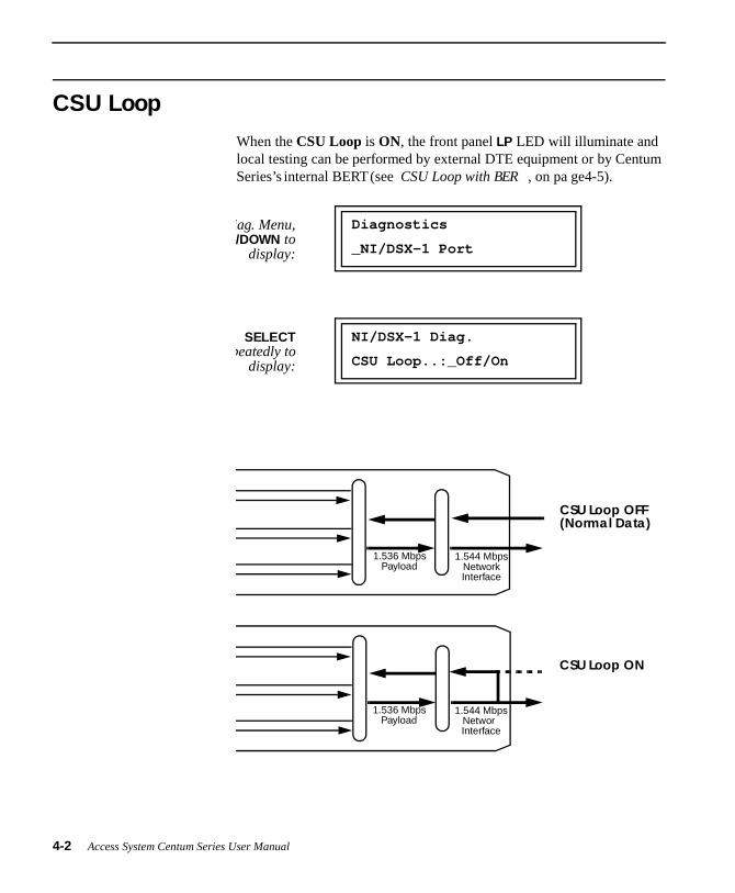
CSU Loop
When the CSU Loop is ON, the front panel LP LED will illuminate and local testing can be performed by external DTE equipment or by CentSeries’s internal BERT (see CSU Loop with BER , on pa ge4-5).
Diagnostics
_NI/DSX-1 Port
iag. Menu,/DOWN to
display:
NI/DSX-1 Diag.
CSU Loop..:_Off/On
SELECTpeatedly to
display:
1.536 Mbps 1.544 Mbps
CSU Loop OFF(Normal Data)
1.536 Mbps 1.544 Mbps
CSU Loop ON
Payload NetworkInterface
Payload NetworInterface
4-2 Access System Centum Series User Manual

be
Payload BERT
The Payload BERT is useful in a point-to-point environment. The Centum Series units at both ends of the circuit must be placed in a Payload BERT condition with the same BER pattern.
SELECT as required to choose the desired Bit Error Rate pattern of 511, 2 of 16, or All Ones.
If the BER pattern was changed in the previous step, the BERT must turned OFF and back ON again to establish the new pattern.
If the CSU portions of the Centum Series unit and the T1 link are all functioning properly, the Seconds/Test at both units will increment while the Errored Seconds at both units will remain at ∅∅∅∅∅.
WHEN TESTING IS COMPLETED, BE SURE TO TURN BOTH BERT TESTS “OFF”.
Diagnostics
_NI/DSX-1 Port
iag. Menu,/DOWN to
display:
NI/DSX-1 Diag.
BER Patt>_XXX
DOWN todisplay:
NI/DSX-1 Diag.
BERT......:_On
d SELECTrequired to
display:
NI/DSX-1 Diag.
Sec/Test.:_ ∅∅∅∅∅
d SELECTrequired to
display:
Access System Centum Series User Manual4-3

Figure 4-1 Payload BERT diagram
Payload BERT ONDetector
Test PatternGenerator
1.536 Mbps 1.544 MbpsPayload Network
Interface
4-4 Access System Centum Series User Manual

4-2
CSU Loop with BERT
The CSU portion of a single Centum Series unit can be tested by activating both the CSU Loop and the Payload BERT. Refer to page and page 4-3.
If the CSU portion of the unit is functioning properly, the Seconds/Test will increment while the Errored Seconds will remain at ∅∅∅∅∅.
WHEN TESTING IS COMPLETED, BE SURE TO TURN BOTH THE LOOP AND THE BERT TESTS “OFF”.
Figure 4-2 CSU Loop with BERT
CSU Loop andDetector
Test PatternGenerator
1.536 Mbps 1.544 MbpsPayload Network
Interface
Payload BERTboth ON
Access System Centum Series User Manual4-5
e
by
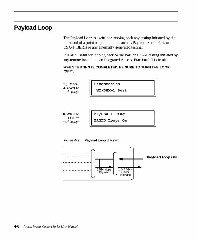
Payload Loop
The Payload Loop is useful for looping back any testing initiated by thother end of a point-to-point circuit, such as Payload, Serial Port, or DSX-1 BERTs or any externally generated testing.
It is also useful for looping back Serial Port or DSX-1 testing initiated any remote location in an Integrated Access, Fractional-T1 circuit.
WHEN TESTING IS COMPLETED, BE SURE TO TURN THE LOOP “OFF”.
Figure 4-3 Payload Loop diagram
Diagnostics
_NI/DSX-1 Port
iag. Menu,/DOWN to
display:
NI/DSX-1 Diag.
PAYLD Loop:_On
DOWN andELECT asto display:
1.536 Mbps 1.544 Mbps
Payload Loop ON
Payload NetworInterface
4-6 Access System Centum Series User Manual

t end
k
g
Line Loop
LLB causes a local line loop (at the Centum Series unit where the command was entered). RLB causes a remote line loop (at the distanof a point-to-point circuit); RLB should not be attempted in an IntegratedAccess, Fractional T1 environment.
The CSU is excluded from the test path in a Line Loop configuration.
In a point-to-point circuit, the LLB and RLB are useful for looping bacany testing initiated by the other end, such as Payload, Serial Port, orDSX-1 BERTs or any externally generated testing.
In an Integrated Access, Fractional T1 circuit, LLB is useful for loopinback Serial Port or DSX-1testing initiated by any remote location.
WHEN TESTING IS COMPLETED, BE SURE TO TURN THE LOOP “OFF”.
Diagnostics
_NI/DSX-1 Port
iag. Menu,/DOWN to
display:
NI/DSX-1 Diag.
NI LLB...:_On
DOWN andELECT asto display:
NI/DSX-1 Diag.
NI RLB...:_On
DOWN andSELECT asto display:
OR
Access System Centum Series User Manual4-7

Figure 4-4 Line Loop diagram
1.536 Mbps 1.544 Mbps
Line Loop ON
Payload NetworInterface
4-8 Access System Centum Series User Manual

nal.
DSX-1 Loop
The DSX-1 Loop is useful for checking PBX cabling to the Centum Series units. With the loop enabled and all equipment properly configured, an attached PBX will synchronize onto its own looped sig
WHEN TESTING IS COMPLETED, BE SURE TO TURN THE LOOP “OFF”.
Figure 4-5 DSX-1 Loop diagram
Diagnostics
_NI/DSX-1 Port
iag. Menu,/DOWN to
display:
NI/DSX-1 Diag.
CSU Loop..:_Ooff
ELECT todisplay:
NI/DSX-1 Diag.
DSX-1 Loop:_Off
/DOWN todisplay:
NI/DSX-1 Diag.
DSX-1 Loop:_On
SELECT todisplay:
1.536 Mbps 1.544 Mbps
DSX-1 Loop ON
Payload NetworkInterface
Access System Centum Series User Manual4-9

l Port t,
ical e
Serial Port Loop
Local Loop ON causes a loop (at the Centum Series unit where the command was entered). Remote Loop ON causes a loop at the Seriaat the distant end. In an Integrated Access, Fractional T1 environmenthe Serial Port #1 and Serial Port #2 links through the network is a logpoint-to-point connection and the “distant end” is the destination for thserial port data.
CAUTIONLocal and Remote Loops should not be activated at the same time unless the serial port BERT is also activated at the local end. (See Serial Port BERT, on page 4-12).
WHEN TESTING IS COMPLETED, BE SURE TO TURN THE LOOP “OFF”.
!
Diagnostics
_Serial Port #1 (or 2)
iag. Menu,/DOWN to
display:
SP 1 (or 2) Diagnostics
Local Loop: On
DOWN andELECT asto display:
SP 1 (or 2) Diagnostics
Remote Loop: On
DOWN andSELECT asto display:
OR
4-10 Access System Centum Series User Manual

Figure 4-6 Serial Port Loop diagram
1.536 Mbps 1.544 Mbps
Serial Port #1Loop ON
Payload NetworkInterface
Access System Centum Series User Manual4-11

test rial ded
left
Serial Port BERT
The Serial Port (DTE) BERT can be used as a part of many different configurations. It is most valuable with both the Local and Remote SePort Loops activated (see page 4-10); the local end of the recommenconfiguration is shown below.
The “Local” Errored Seconds are counted by the detector toward the side in the figure. The “Remote” Errored Seconds are counted by thedetector toward the right side.
WHEN TESTING IS COMPLETED, BE SURE TO TURN THE LOOP AND BERT “OFF”.
Diagnostics
_Serial Port #1 (or 2)
iag. Menu,/DOWN to
display:
SP 1 (or 2) Diagnostics
_BERT.....: On
SELECT todisplay:
SP 1 (or 2) Diagnostics
_Loc ES...:_ ∅∅∅∅∅
DOWN andSELECT asto display:
SP 1 (or 2) Diagnostics
_Rem ES...:_ ∅∅∅∅∅
DOWN andELECT asto display:
SP 1 (or 2) Diagnostics
_Sec/Test.:_ ∅∅∅∅∅
DOWN andSELECT asto display:
4-12 Access System Centum Series User Manual

Figure 4-7 Serial Port BERT and Loop diagram
tector
Test Patternnerator Detector
Generator
1.536 Mbps 1.544 Mbps
Serial Port #1BERT and
Payload NetworInterface
Loop ON
Access System Centum Series User Manual4-13

4-14 Access System Centum Series User Manual

Chapter
r n
,
e
re sent
r 6,
ving
5 Other Features
Many other functions are available in the Centum Series. This chaptedescribes access from the front panel display. The same functions caalso be accessed via an externally attached terminal. See Chapter 6Auxiliary Ports.
Alarms and Statistics
The Alarms and Stats Main Menu is intended for those users with T1 alarm and ESF (Extended Superframe) statistics knowledge. From thAlarms and Stats Main Menu, SELECT then use UP/DOWN arrows to:
■ Access current network (NI) and DSX-1 alarm conditions, which ashown with the number of seconds that the alarms have been presince the last alarm reset.
■ Reset the alarm times.
■ Access both current and 24-hour ESF statistics.
■ Send alarms to an externally attached printer. See Chapter 6, Auxiliary Ports.
■ Send ESF statistics to an externally attached printer. See ChapteAuxiliary Ports.
Alarm Definitions AIS. An unframed “all ones” condition has been detected.
Red Alarm. A “loss of frame alignment” has occurred and synchronization has been lost.
Yellow Alarm. A Yellow Alarm is generated by the network and sent tothe customer premises. It usually means that the network is not receiCentum Series signalling correctly.
Access System Centum Series User Manual5-1

he
a
hat .
Framing Errors. One or more frame alignment bit errors have been detected. This does not mean that synchronization has been lost.
CRC6 Alar m. One or more CRC6 block errors have been detected. TD4 framing does not include CRC6; Centum Series replaces that parameter by counting the number of framing bit errors. The result isuseful picture over time regarding D4 link performance.
BPV. Bipolar Violations have been detected. This usually indicates ta very weak or overly strong signal is being received from the network
ESF Statistics Definitions
Errored Second (ES). Any occurrence of a Loss of Frame or a CRC6 error in a one-second period.
Failed Signal State (FSS). Ten consecutive Errored Seconds.
Failed Second (FS). Each second during the occurrence of a Failed Signal State.
Severely Errored Second (SES ) Three hundred twenty (320) or more CRC6 errors in a one-second period.
Bursty Errored Second (BES). More than one but less than 320 CRC6 errors in a one-second period.
5-2 Access System Centum Series User Manual

s
lay ent.
Alarms/Statistics Menu
Please refer to Alarm Definitions, on page 5-1, and ESF Statistics Definitions, on page 5-2.
This chapter describes front panel access of the Alarms and Statisticstorage. Please refer to page 6-12 for terminal access.
From the Alarms/Stats Main Menu, SELECT then use UP/DOWN arrows to display either NI Alarms , DSX-1 Alarms, or ESF Statistics. Then SELECT followed by UP/DOWN as described below.
NI Alarms will display the current status (Yes/No) of AIS, Red and Yellow Alarms, Frame Errors (Ferr), CRC6 and BPV alarms. UP/DOWN will scroll through the six possible alarms. If any entry is yes, the dispwill also indicated the quantity of seconds that the alarm has been presThe DSX-1 Alarms display is identical to the NI Alarms display except that BPV alarms are not included.
If ESF Statistics is selected, the user is then presented with another choice, Current Statistics, 24-Hour Statistics, or ESF Registers.
By choosing Current Statistics, the user is provided statistics for the current time interval (maximum fifteen minutes). Use UP/DOWN to scroll through Current Status, Time in Current Interval (in seconds), ES & FS, SES & BES, and the current quantity of Valid Intervals (fifteen minutes per interval). In the Current Status screen (shown below), the following interpretation applies.
Digit #1 F or ∅ where F indicates Failed Signal State (FSS).
Digit #2 U or ∅ where U indicates that the T1 line is unavailable.
Digit #3 Always ∅.
Digit #4 Always ∅.
Digit #5 Always ∅.
DSX-1 Alrm Errs
Yel Yes ∅∅∅1∅
Access System Centum Series User Manual5-3

S,
h
the
Scrolling UP/DOWN will provide detailed information. Below is the SES/BES display.
By choosing 24 Hour Stats, the user can scroll through the ES, FS, SEand BES counts for the preceding 24-hour period.
ESF Registers gives the same information but it is broken down for eacof the ninety-six 15-minute intervals in that 24-hour period. Use UP/DOWN to scroll through the intervals.
In this example, the user has scrolled to interval #3. The ES count is first three-digit number (directly below the ∅3).
Digit #6 Always ∅.
Digit #7 L or ∅ where L indicates that the T1 line is in loop.
Digit #7 Always ∅.
Current Stats
Status: XX ∅∅∅∅X∅
Current Stats
SES: ∅∅∅ BES: ∅∅∅
24 Hour Stats
SES: ∅∅∅∅∅
∅3. FS SES BES
∅∅∅ ∅∅∅ ∅∅∅ ∅∅∅
5-4 Access System Centum Series User Manual

ault
Utilities
From the Utilities Main Menu, SELECT then use UP/DOWN arrows to:
■ Set Date and Time.
■ Edit Unit ID.
■ Clear BRAM. This function clears all user-entered configuration parameters and returns the Centum Series unit to the factory defcondition. USE WITH CAUTION.
■ Determine installed software level.
■ Configure Auxiliary CRT Port. See Chapter 6, Auxiliary Ports.
■ Configure Auxiliary NMS/Printer Port. See Chapter 6, Auxiliary Ports.
Access System Centum Series User Manual5-5

as
nter e
and inal
s
Events
Centum Series constantly monitors for the occurrence of events, suchalarms, test commands, and system resets. When an event occurs, adescription with a time and date stamp is immediately sent out the priport. The format and interpretation of printed events are shown on thnext page.
In addition, Centum Series maintains a log of the most recent sixteenevents and that log can be accessed by either the front panel controlsLCD panel or an externally attached terminal. See page 6-15 for termaccess of the Event Log.
From the Event Log Main Menu, SELECT then use UP/DOWN arrows to view the stored events and/or clear the log. (The log is cleared is SELECT is depressed when the screen displays Clear Event Log.) The format of an LCD screen event is below. Interpretation of the events ithe same as shown on the next page for printed events.
NN is the Event sequence number. S indicates that the Event is the Start of an occurrence. E is used to indicate that the Event is the End of an occurrence.
NN S Event Description
HH:MM:SS MM/DD
5-6 Access System Centum Series User Manual

Event Printing
Unit ID Seq. Num Time Date Status Event
0012345 01155 10:39:39 02/25 End PORT 1 LL
FORMAT AND SAMPLE ENTRY
Type Text DescriptionSystem UNIT START Centum Series Power Up of Initialization Sequence
BRAM CLEAR Non-Volatile Memory has been ClearedCFG ERROR Error Detected in Non-Volatile Memory
Alarm NI RED Network Interface is in Red AlarmNI AIS Network Interface is Receiving all “Ones” (AIS)NI YEL Network Interface is Receiving Yellow AlarmNI CRC Network Interface is Experiencing CRC6 ErrorsNI FSS Network Interface is in a Failed Signal StateNI FERR Network Interface is Experiencing Framing Errors
DSX-1 RED DSX-1 Interface is in Red AlarmDSX-1 AIS DSX-1 Interface is Receiving all “Ones” (AIS)DSX-1 YEL DSX-1 Interface is Receiving Yellow AlarmDSX-1 CRC DSX-1 Interface is Experiencing CRC6 ErrorsDSX-1 FERR DSX-1 Interface is Experiencing Framing Errors
Diagnostic DTE1 LL Serial Port #1 is in Local Digital LoopbackDTE2 LL Serial Port #2 is in Local Digital LoopbackDTE1 RL Serial Port #1 is in Remote Digital LoopbackDTE2 RL Serial Port #2 is in Remote Digital Loopback
NI LLB The Network Interface is in Local Line LoopbackNI RLB The Network Interface is in Remote Line LoopbackNI PLLB The Network Interface is in Payload LoopbackNI CSU LL The Network Interface is in Local CSU Loopback
Indications DTE 1 CONN Serial Port #1 is Connected (DTR/RTS Asserted)DTE 1 DISC Serial Port #1 is DisconnectedDTE 2 CONN Serial Port #2 is Connected (DTR/RTS Asserted)DTE 2 DISC Serial Port #2 is Disconnected
Access System Centum Series User Manual5-7

5-8 Access System Centum Series User Manual

Chapter
al he
ser s
l-
6 Auxiliary Ports
The Centum Series includes two RS-232 “auxiliary” ports. The CRT port allows the user to connect an external terminal (or PC with terminemulation). The connected terminal can perform all the functions of tUP, DOWN, SELECT, and END buttons on the front panel. Usage of thisterminal is highly recommended by Verilink as the CRT display is not constrained by the limitations of the LCD panel and, as a result, the uis presented with a more comprehensive indication of available choiceand Centum Series results.
The NMS/Printer port allows the user to connect an external serial printer to obtain a hard copy of configuration, statistics, alarm and reatime events.
Access System Centum Series User Manual6-1

or
is
are g,
Cabling
The table below provides a summary of the Verilink cables available fthe Centum series.
Table 6-1
For additional cable and pinout detail, see the following sections of thmanual:
■ Appendix B, Standard Cabling for User Ports
■ Appendix C, Special Serial Port Cabling.
Auxiliary ports Both auxiliary ports consist of 6-pin modular jacks. Because the portspermanently DCE, there are two configurations for the required cablindepending on whether the connections are “direct” or via modems.
Verilink Cable Number Length Description Type of Cable
CBE 010-00001 15 ft. 8-pin to 8-pin modular Male-to-Male for network connection
Networ
CBE 011-00001 15 ft. 8-pin to 8-pin modular Male-to-Male for equipment connection
T1 Equipment
CBE 010-00002 4 ft. 6-pin modular to 25D-type Female for direct connection
Management
458-502368-008 8 ft. 6-pin modular to 25D-type Male for modem connection Management
458-501983-015 15 ft. V.35 Male to Male, DCE to DTE Application
458-501792-015 15 ft. 25D-type with RS-530 specification. Male-to-Male Application
458-501776-015 15 ft. V.35 Male-to-Male for external timing a Application
458-501791-015 15 ft. RS-530 Male-to-Male for external timinga Application
Adapter Cables b (below)
458-502361-015 15 ft. 25D-type (RS-530) Male to 37-pin (RS-449) Female Application
458-502362-015 15 ft. 25D-type (RS-530) Male to 37-pin (RS-449) Male Application
458-502363-015 15 ft. 25D-type (RS-530) Male to 37-pin (RS-449) Female for external timinga
Application
458-502364-015 15 ft. 25D-type (RS-530) Male to 37-pin (RS-449) Male for external timinga
Application
a. External Timing is the same as DSU-X, for a cross-over cable.
b. Adapter cables are used to convert between a 25-pin connector on the rear of the box to a 37-pin connector on the customer apparatus.
6-2 Access System Centum Series User Manual

.
le ular
on
NMS Access (Management Port) Cable. Six-position, 6-pin modular male to 25-pin D-type male for direct connection of a terminal or a printer. Four feet long. One cable supplied with unit.
458-502368- 0 0 8Six-position, 6-pin modular male to 25-pin D-type male for modem connection of a terminal or a printer. Eight feet longAvailable at extra cost.
The Verilink cables can be “stretched” by adding a 6-pin female/femaadapter and a straight-through 6-wire make/male modular cable (seebelow). If the user chooses not to obtain Verilink cables, a male/malemodular cable should be used with a connector adapter (female modto D-25). See next page for adapter construction.
In any case, the 6-wire reference must be emphasized. A very commmodular cable is 6-position, 4-wire (such as used in the RJ-11 configuration for a home telephone). Although the plastic housing is identical to the 6-wire version, ONLY FOUR WIRES ARE IN THE CABLE AND IT WILL NOT FUNCTION WITH THE CENTUM SERIES.
The device is shipped with the following cables:
Part Number AS100 AS150 AS200
CBE 010-00001 Network Cable Network Cable Network Cable
CBE 011-00001 ----- DSX-1 Cable -----
CBE 010-00002 Management Cable Management Cabl Management Cable
Pins
Pins
Connectors are “flipped” on a straight-through cable
NOTE
Access System Centum Series User Manual6-3

e
el is
To/F
rom
Mo
dem
To/F
rom
Term
ina
lo
r Prin
ter
Modular Adapters
If Verilink cables will not be used, the adapters shown below should bused with straight-through male/male 6-wire modular cables. See previous page for a description of the available Verilink cables.
Figure 6-1 6-Pin Modular Ada pter Pin Assignment
Rear panel views The three following figures show the rear panel views of the AS100, AS150, and AS200, respectively. As an example, the AS150 rear panlabeled in detail.
Figure 6-2 Rear Panel of Access System 100 (V.35 version)
123456
6-pinModular
Jack(Female)
Signal Ground Carrier Detect
Request to Send Receive Data Transmit DataPower Ground
Signal Ground Carrier Detect
Request to Send Receive Data Transmit DataPower Ground
784321
Direct Connection
123456
6-pinModular
Jack(Female)
Signal Ground Carrier Detect
Request to Send Receive Data Transmit DataPower Ground
Signal Ground Request to SendCarrier DetectTransmit Data Receive Data
Power Ground
748231
Modem Connection
DB-
25 P
ins
DB-
25 P
ins
PRN AUX N.I.
PORT #1V.35
6-4 Access System Centum Series User Manual

Figure 6-3 Rear Panel of Access System 150 (V.35 version)
Figure 6-4 Rear Panel of Access System 200 (V.35 version)
PRN AUX N.I.
PORT #1V.35
V.35 DTEt and NMS Access
Terminal Access-48 Configuration) Power cord connection
M-series 34-pin Receptacle6-pin
Modular Jacks
8-pinModular
Jack
-48 Configuration)
PRN AUX N.I.
PORT #2V.35
PORT #1V.35
Access System Centum Series User Manual6-5

e
ull n
er
n
e e it.
Terminal Configuration
The AUX (Terminal Access) Port supports automatic speed detection(AutoBaudRate or ABR). This should be noted before connecting a terminal to the AUX Port for configuration or monitoring functions. ThAUX port will detect the following speeds: 1200, 2400, 4800, and 9600 bps.
The terminal should be configured for any of the above speeds, and fduplex, 8 data bits, 1 stop bit and no parity (8,1,N) for the ABR functioto operate correctly. The terminal must present DTR (Data Terminal Ready — Pin 4 of the RS-232C (DB-25) connector) to AS100 for propoperation. Within those restrictions, all common terminal types are supported.
To operate:
1. Connect the terminal to the AUX (Terminal Access) Port using thecable supplied with the Centum Series unit.
2. Apply power to the unit and ensure that it performs its initializatiocycle successfully and displays the Main Menu on the front panelLCD display. Turn on the terminal.
3. When the terminal has finished its initialization cycle and is fully operational, depress the <CARRIAGE RETURN> key once or twice. The unit will respond with the following text:
==>Verilink Corporation Access System 150 SeriesPlease Enter Your Password Now!Depress [ENTER] key to register your password.==>
At login and on each screen, the text will reflect the appropriate unit —AS100, AS150, or AS200 — and its Unit ID number. The user has thoption to access the Unit ID number through the menu tree and chang
The default password is <CARRIAGE RETURN>.
NOTE
6-6 Access System Centum Series User Manual

a is ility
ched
on uery
4. The Centum Series unit will respond with the following text:
The Centum Series port depends on RTS from a terminal (or CD frommodem) to indicate a connected device. Every time that RTS (or CD)lowered and subsequently raised, Centum Series assumes the possibthat a different terminal type is attached and therefore queries the attadevice with a generic Terminal Selection message (see above). If thismessage does not appear on the screen, temporarily disconnect andreconnect the cable.
After selecting a terminal type, the user is presented with a Main Menuthe CRT screen and is allowed access to all configuration, test, and qfunctions provided by Centum Series.
Add 1 screenVerilink CorporationAccess System 150Terminal Selection Menu
(A) A.D.D.S. Viewpoint (B) A.D.D.S Regent 25 (C) Data General DASHER (D) Datamedia 1521 (E) Datamedia EXCEL 30 (F) DEC VT-52 (G) DEC VT-100/131/220 (H) IBM 3101 (I) Datamedia EXCEL 42 (J) FREEDOM 100 (K) ICL 6401 (L) L.S.I. ADM 11, 31 (M) Qume QVT-102, 108 (N) Televideo 900 Ser. (O) Wyse WY-50 (P) Paradyne 7811 (Q) Teletype 5410, 5425 (R) ATTIS 4410, 4425
==> Enter Terminal Selection..
Access System Centum Series User Manual6-7

ns e of enu the
Terminal Operation
Because the terminal functions are identical to the front panel functiopreviously described in this manual (except for a more comprehensivdisplay), their descriptions are not repeated here. Instead, examplessome possible screen displays are shown, beginning with the Main Mbelow. The user is advised to peruse the CRT menus while reviewingfront panel descriptions. In all cases, SPACE advances the cursor, BS moves the cursor back, ENTER or RETURN selects an entry, and ESC acknowledges an alarm.
Add 1 screen
==>
**** **** **** **** MAIN MENU **** **** **** **** System Configuration **** **** Diagnostics & Indicators ***** **** Link Alarms and Statistics **** **** ESF Registers **** **** Event Log ******** System Utilities ******
Cursor Forward = [SPACE] Verilink Corporation Cursor Back = [BS] Access System 150 T-1 D&I DSU/CSU Select Entry = [ENTER] Software: VER 3053_51 Acknowledge Alarm = [ESC]
Deactivate Console = [X] Mar 18, 1995 14:34:00 Hangup Modem = [Ctrl-E] Unit ID........: 30000000 DNS Front Panel: ENABLED System Status..: OK
6-8 Access System Centum Series User Manual

on
e 1”
um
Configuration Menus
From the terminal’s Main Menu, the user has selected System Configuration and is presented with the next menu shown. From thismenu, the user can view and/or change all Centum Series configuratiparameters. Please refer to Chapter 3, Configuring and Installing the Centum Series, before changing any parameter(s).
By selecting View DS0 Allocations, the user can view all DS0 assignments on a single screen. This is the same function as Checking the “T-Channels”, on page 3-19.
Note that “Idle” refers to channels that have been configured as “Not Used” in the Centum Series. In some cases, typically involving Fractional T1, a portion of the DS0s assigned to the DSX-1 port will bforced to “idle” by the PBX; these channels will be displayed as “DSX-channels by the Centum Series. The user is advised to mark the Worksheet in such a way that PBX idle can be differentiated from CentSeries idle.
Access System Centum Series User Manual6-9

Add 1 screen
Verilink Corporation Mar 09, 1995Access System 150 T-1 Drop-and-Insert CSU/DSU 20:26:00Unit ID: 30000000 SYSTEM CONFIGURATION
Network (NI) DSX-1 Serial Port ConfigurationConfiguration Configuration Port #1
Framing...: ESF Framing...: N/U Speed....: 1536k (24 DS0)Line Code.: B8ZS Line Code.: AMI First DS0: 01LBO.......: 0 db Distance..: 100ft DS0 Order: Consec. DS0sDensity...: Clear DCD......: OffNTWK Loops: Yes Data.....: NormYellow Alm: Yes Clock....: NormESF Format: T1.403 Timing...: InternalCRT Alarm.: On Rem Loop.: Enabled
System ClockSource....: Port 1 Quit Configuration = [Q] View DS0 Allocations = [V] Save New Configuration = [S] or [X] Cursor Forward = [SPACE] Next/Previous Entry = [ENTER]/[B] Cursor Back = [BACKSPACE] Return to Previous Menu = [X]
Add 1 screen
Verilink Corporation Mar 09, 1995Access System 150 T-1 Drop-and-Insert CSU/DSU 20:26:00Unit ID: 30000000
T-Channel (DS0) Allocation
DS0 # Mode DS0 # Mode 01: Port 1 13: Idle 02: Port 1 14: Idle 03: Port 1 15: Idle 04: Port 1 16: Idle 05: Port 1 17: Idle 06: Port 1 18: Idle 07: Port 1 19: Idle 08: Port 1 20: Idle 09: Port 1 21: Idle 10: Port 1 22: Idle 11: Port 1 23: Idle 12: Port 1 24: Idle
Return to System configuration Menu + [X]
6-10 Access System Centum Series User Manual

will
Serial Port Diagnostics
The user has selected Diagnostics and Indicators from the terminal’s Main Menu and is presented with the menu depicted below.
This menu provides the functions described in Chapter 4, Testing the Centum Series, page 4-10 and page 4-12.
Also, see the description, Alarms and Statistics, on page 5-1.
If the device has two serial ports, a second set of Serial Port columnsbe shown on the right half of the screen.
Add 1 screenVerilink Corporation Mar 18, 1995Access System 150 T-1 Drop-and-Insert CSU/DSU 20:26:00Unit ID: 30000000
System Diagnostics & Indicators
Serial Port #1
Diagnostics Indicators
Local Loop.: Off Rx Data.: OffRemote Loop: Off Tx Data.: OffBERT.......: Off RTS.....: Off
DCD.....: OffLocal ES...: 00000 DTR.....: OffRemote ES..: 00000 Loop Ind: OffSec in Test: 65535
Cursor Forward = [SPACE] Select Entry = [ENTER] Cursor Back = [BACKSPACE] Return to Previous Menu = [X]
TIP
Access System Centum Series User Manual6-11

nu tics
Link Alarms and Statistics
The user has selected Link Alarms and Statistics from the terminal’s Main Menu and is presented with the menu depicted below. This meprovides access to Network and DSX-1 Alarms and Network diagnos(see Chapter 4, page 4-2 through page 4-6). Also see Chapter 5, Alarms and Statistics, on page 5-1.
Add 1 screen
Verilink Corporation Mar 18, 1995Access System 150 T-1 Drop-and-Insert CSU/DSU 20:26:00Unit ID: 30000000 System Alarms and Statistics
Network Interface (NI) Network Interface (NI) DSX-1 Interface Alarms Diagnostics Alarms State ErrSec State ErrSec AIS No 00000 CSU Loop..: Off AIS No 00000 Red No 00001 NI LLB....: Off Red No 00000 Yel No 00000 NI RLB....: Off Yel No 00000 Ferr No 00001 PAYLD Loop: Off Ferr No 00000 CRC6 No 00001 DSX-1 Loop: Off CRC6 No 00000 BPV No 00000 LOS No 00001 Loop Ind...: Off BER Pattern: 1 of 8 BERT.......: Off >> [E] to Insert BER Errors Err Secs...: 00000 Sec/Test...: 00000
Reset Counters = [R] Cursor Forward = [SPACE] Select Entry = [ENTER] Cursor Back = [BACKSPACE] Return to Previous Menu = [X]
6-12 Access System Centum Series User Manual

ESF Registers
From the terminal’s Main Menu, the user has selected ESF Registers and is presented with the following menu.
The user can then proceed to this next menu for detailed information.These menus provide the functions described in Alarms and Statistics, on page 5-1.
Add 1 screen
Verilink Corporation Mar 18, 1995Access System 150 T-1 Drop-and-Insert CSU/DSU 20:26:00Unit ID: 30000000
ESF Registers
ESF Statistics
Register Current 24 Hour
Errored Seconds.........: 000 00001 Failed Seconds (UAS)....: 000 00000 Severely Errored Seconds: 000 00001 Bursty Errored Seconds..: 000 00000 Loss of Frame Count.....: 000 00000
Time in Interval........: 150 # Valid Intervals.......: 093 ESF Status..............: 00000000
Display ESF Network Registers = [R] Return to Previous Menu = [X]
Access System Centum Series User Manual6-13

Add 1 screen
Verilink Corporation Mar 18, 1995Access System 150 T-1 Drop-and-Insert CSU/DSU 20:26:00Unit ID: 30000000 ESF Registers
INT ES FS SES BES INT ES FS SES BES INT ES FS SES BES 01. 001 000 001 000 17. 000 000 000 000 33. 000 000 000 000 02. 001 000 001 000 18. 000 000 000 000 34. 000 000 000 000 03. 001 000 001 000 19. 000 000 000 000 35. 000 000 000 000 04. 001 000 001 000 20. 000 000 000 000 36. 000 000 000 000 05. 001 000 001 000 21. 000 000 000 000 37. 000 000 000 000 06. 001 000 001 000 22. 000 000 000 000 38. 000 000 000 000 07. 001 000 001 000 23. 000 000 000 000 39. 000 000 000 000 08. 001 000 001 000 24. 000 000 000 000 40. 000 000 000 000 09. 001 000 001 000 25. 000 000 000 000 41. 000 000 000 000 10. 001 000 001 000 26. 000 000 000 000 42. 000 000 000 000 11. 001 000 001 000 27. 000 000 000 000 43. 000 000 000 000 12. 001 000 001 000 28. 000 000 000 000 44. 000 000 000 000 13. 001 000 001 000 29. 000 000 000 000 45. 000 000 000 000 14. 001 000 001 000 30. 000 000 000 000 46. 000 000 000 000 15. 001 000 001 000 31. 000 000 000 000 47. 000 000 000 000 16. 001 000 001 000 32. 000 000 000 000 48. 000 000 000 000
Continue = [ENTER] Return to Previous Menu = [X]
6-14 Access System Centum Series User Manual
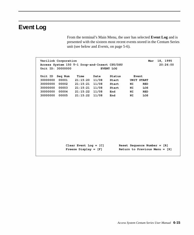
eries
Event Log
From the terminal’s Main Menu, the user has selected Event Log and is presented with the sixteen most recent events stored in the Centum Sunit (see below and Events, on page 5-6).
Add 1 screen
Verilink Corporation Mar 18, 1995Access System 150 T-1 Drop-and-Insert CSU/DSU 20:26:00Unit ID: 30000000 EVENT LOG
Unit ID Seq Num Time Date Status Event30000000 00001 21:15:20 11/08 Start UNIT START30000000 00002 21:15:21 11/08 Start NI RED30000000 00003 21:15:21 11/08 Start NI LOS30000000 00004 21:15:22 11/08 End NI RED30000000 00005 21:15:22 11/08 End NI LOS
Clear Event Log = [C] Reset Sequence Number = [R] Freeze Display = [F] Return to Previous Menu = [X]
Access System Centum Series User Manual6-15
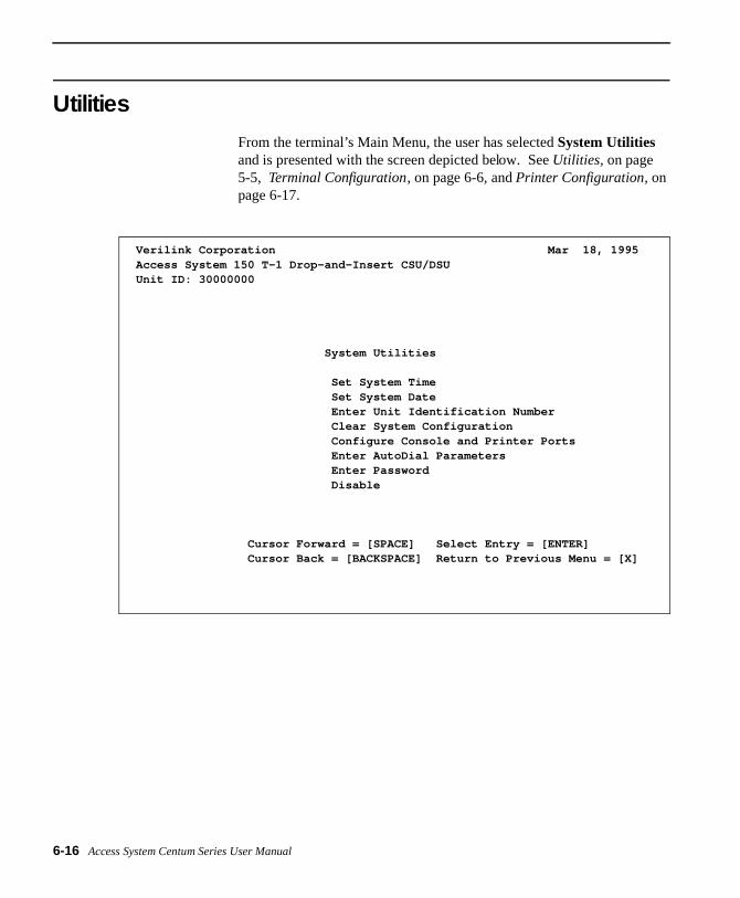
Utilities
From the terminal’s Main Menu, the user has selected System Utilities and is presented with the screen depicted below. See Utilities, on page 5-5, Terminal Configuration, on page 6-6, and Printer Configuration, on page 6-17.
Add 1 screen
Verilink Corporation Mar 18, 1995Access System 150 T-1 Drop-and-Insert CSU/DSU Unit ID: 30000000
System Utilities
Set System Time Set System Date Enter Unit Identification Number Clear System Configuration Configure Console and Printer Ports Enter AutoDial Parameters Enter Password Disable
Cursor Forward = [SPACE] Select Entry = [ENTER] Cursor Back = [BACKSPACE] Return to Previous Menu = [X]
6-16 Access System Centum Series User Manual

m
R.
Printer Configuration
To configure the SERIAL1 Printer port, use the Centum Series control panel to enter (SELECT) the Utilities menu. Use the UP/DOWN arrows to locate NMS/Prt Port and the SELECT again. If necessary, use the UP/DOWN arrows to locate Mode.
Repeatedly SELECT until the mode indicates Printer . Note that the NMS function is not operational in this Centum Series revision.
Use the UP or DOWN arrow to display Speed and then SELECT to choose the desired printer data rate. Finally, END twice to return to the Main Menu.
The printer should be configured for the same data rate as the CentuSeries printer port and 8-N-1 character coding. All data is output withboth a CR and an LF at the end of each line. Printer “word wrap” is unnecessary and the printer should not add an LF to each received C
1. This is a non-standard printer port. Most printers are parallel, not serial.
Access System Centum Series User Manual6-17

re l is .
O
he ies. ill or
ill
Printer Port Flow Control
The Centum Series port supports simultaneous hardware and softwaflow control signaling from the attached device. The hardware controRTS if connected directly to a printer or CD if connected via a modemThe software control is XOFF/XON. The XOFF is DC-3 (Cntl-S); however, any character arriving at the port is treated as an X(to protect against a damaged DC-1).
Hardware control has priority: If RTS (or CD) is low, transmission to tdevice will be suspended and the data will be buffered in Centum SerReceipt of software flow control characters while RTS (or CD) is low whave no effect on the port. Transmission will be resumed when RTS (CD) goes high.
If the port receives an XOFF while RTS (or CD) is high, transmission wbe suspended and the data will be buffered. Transmission will be resumed if any subsequent character (including another XOFF) is received or if RTS (or CD) is lowered and subsequently raised. This mechanism protects against a “lost” XON.
6-18 Access System Centum Series User Manual

e
Printer Operation
Events are automatically sent (real-time) to the printer. See Event Printing, on page 5-7. Other print functions are available from both thfront panel and the external terminal.
From the Main Menu, SELECT the Configuration menu and use the arrow buttons to display Print Config . Then SELECT to initiate a printout.
From the Main Menu, SELECT the Alarms/Stats menu and use the arrowbuttons to display either Print Alarms or Print ESF Stats. Then, SELECT to initiate a printout.
Terminal control provides a much more comprehensive printing capability with CRT formatting: entering a P on the appropriate screen will cause a printout of Configuration , DS0 Assignments, Link Statistics, Alarms, ESF Register Summar, and Complete ESF Register Contents.
Access System Centum Series User Manual6-19

nu
Link Alarms and Statistics
The user has selected Link Alarms and Statistics from the terminal’s Main Menu and is presented with the menu depicted below. This meprovides access to Network Alarms and Network Diagnostics (see Chapter 4, Testing the Centum Series).
6-20 Access System Centum Series User Manual

Appendix
nits
orts r is us
he MP
er. t s
l or n is unit
A SNMP Managemen
This appendix describes the management of Centum Series units equipped with the Verilink embedded SNMP agent.
Connecting the Centum Series
This section describes two options for connecting the Centum Series ufor use with SNMP management.
Option #1 The Centum Series comes equipped with two RS-232 asynchronous pintended for the purpose of device management. The AUX connectointended for use with a VT-100 style ASCII terminal and supports menfor the user to edit the device configuration and diagnostic options. TNMS/PRT connector is intended to be used as a printer port (non-SNversion or the NMS port (SNMP version).
The Centum Series unit connects to an SNMP network management station such as HP Open Vie or Sun’s NetManager by either LAN or modem. Either method must support UDP/IP/SLIP over RS-232. Themost straightforward method would be to connect the Centum SeriesNMS port to an intelligent port on either a router, hub, or terminal servThe intelligent port must be configured to run SLIP protocol. The porspeed must be set as well as the IP address for the port and the port’remote device (in this case, the Centum Series unit).
The NMS Port on the DNS must be configured from either the terminafront panel display. The port must first be configured for SNMP NMS,and then the baud rate for the port must be configured. The final optiofor the user to configure the internet address that the Centum Series will respond to once connected to the LAN (via terminal server) or modem. Reference the diagram for the proper connection.
Access System Centum Series User ManualA-1

ame
m
In Figur eA-1, the terminal server is permitting Ac cessSy stem100 toaccess the LAN for SNMP management purposes. If multiple CentumSeries units are co-located, they all may access the LAN through the sserver (using a multi-port server).
Figure A-1 SNMP Manager access with a terminal server
In Figur eA-2, an RS-232 (SLIP) port on the router is permitting CentuSeries to access the LAN for SNMP management purposes.
SERIAL PORT #1 PRN/AUX N.I.NMS
Async (VT100) Terminal(OPTIONAL)
T-1 WAN
SNMPNetwork Manager
Terminal Server/Hub (Intelligent Port)
V.35/RS-422 WAN Port
Router
6-wire/8-wire ‘Barrel’ Converter
CBE 010 00002
DTE Cable
LAN
AS100
A-2 Access System Centum Series User Manual

ries
The r
Figure A-2 SNMP Manager access with a router
Option #2 Another method allows the SNMP Manager to access the Centum Sewithout the terminal server. This is by way of a direct or dial-up connection over an RS-232 port on the SNMP management station. SNMP Network Management System must support UDP/IP/SLIP ovethe asynchronous serial link. This connection is diagrammed in Figur eA-3.
Figure A-3 SNMP Manager access via direct or dial-up connection
SERIAL PORT #1 PRN/AUX N.I.NMS
Async (VT100) Terminal(OPTIONAL)
T-1 WAN
SNMPNetwork Manager
V.35/RS-422 WAN Port
Router
CBE 010 00002
DTE Cable
LAN RS-232 (SLIP)Router Port
AS100
Access System Centum Series User ManualA-3

SERIAL PORT #1 PRN/AUX N.I.NMS
Async (VT100) Terminal(OPTIONAL)
T-1 WAN
SNMPNetwork Manager
V.35/RS-422 WAN Port
Router
Modem CBE 010 00002DTE Cable
LAN
Switched PublicNetwork
Modem
458-501764-008DCE Cable
AS100
A-4 Access System Centum Series User Manual

s t
”
the sk ing this
Compiling the Centum Series MIB
After the Centum Series unit has been connected to the SNMP management station by one of the methods mentioned in the previousection, the unit may be “pinged” to ensure connectivity. After this teshas been passed, you are ready to manage the Centum Series unit.
The Centum Series SNMP agent comes equipped with MIB-II and theRFC-1232 DS1 MIB. These may be managed without any MIB compilation. However, to manage the device fully, you must install theVerilink Centum Series MIB, which is supplied on a DOS diskette (3.5high-density micro floppy).
The Verilink Centum Series MIB must be compiled once it has been copied to the management station’s hard disk medium in order to addCentum Series objects to the management information base. This tawill be different depending on which management software you are usand requires a MIB browse function to be present on the manager. Ifis not the case, then you must design an NMS application for CentumSeries on your management platform.
Access System Centum Series User ManualA-5

A-6 Access System Centum Series User Manual

Appendix
r
are
ith
B Standard Cabling for User Ports
Network Interface and DSX-1 Por
The Network Interface and the DSX-1 Port both use an 8-pin modulajack in an RJ-48 configuration. The figures to the right show the pin numbering and the pin assignments of the two jacks. Verilink cables recommended:
Network Interface Cable. Eight-position, 8-pin male/male modular cable (RJ-48 configuration). Used for connecting the NI port to the supplier’s network interface. Fifteen feet long. One cable supplied wunit. Additional cable optional at extra cost.
Figure B-1 Network Interface and DSX-1 Port (RJ-48)
Pin Signal
To/From Access System
100
1 Receive To
2 Receive To
3 Not Used -----
4 Transmit From
5 Transmit From
6 Not Used -----
7 Optional Shield Ground -----
8 Optional Shield Ground -----
1 2 3 4 5 6 7 8
Access System Centum Series User ManualB-1

r. ling
V.35 Serial Port
V.35 signaling is provided through a female M-series, 34-pin connectoThe connector and its pin assignments are shown below. Verilink cabis recommended.
458-501983- 0 1 5V.35 straight-through cable. M-series, 34-pin male connectors at both ends. Fifteen feet long. Optional at extra cost.
Figure B-2 V.35 Serial Port Pin Assignments (M-series, 34-pin connector)
Pin Signal
To/From Access System
100
Y Transmit Clock (A) From
V Receive Clock (A) From
U Ext. Transmit Clock (A) To
P Transmit Data (A) To
R Receive Data (A) From
AA (a) Transmit Clock (B) From
X Receive Clock (B) From
W Ext. Transmit Clock (B) To
S Transmit Data (B) To
T Receive Data (B) From
C Request to Sen To
F Data Carrier Detect From
D Clear to Send From
H Data Terminal Ready To
E Data Set Ready From
B Signal Ground ------
B-2 Access System Centum Series User Manual

le, the ng
s at
RS-442A Serial Port
RS-422A Category I signaling is provided through a female DB-25 connector per the RS-530 specification. With an external adapter cabthe same signals are provided through a female DB-37 connector perRS-449 specification. The pin assignments are shown. Verilink cabliis recommended:
458-501792- 0 1 5D-type 25-pin (DB-25) male connectors at both end(in compliance with RS-530 specification). Fifteen feet long. Optionalextra cost.
RS-530 (DB-25)
Connector
RS-449 (DB-37) Adapter Signal
To/From Access System
100
15 5 Transmit Clock (A) From
17 8 Receive Clock (A) From
24 17 Ext. Transmit Clock (A) To
2 4 Transmit Data (A) To
3 6 Receive Data (A) From
12 23 Transmit Clock (B) From
9 26 Receive Clock (B) From
11 35 Ext. Transmit Clock (B) To
14 22 Transmit Data (B) To
16 24 Receive Data (B) From
4 7 Request to Send (A) To
8 13 Data Carrier Detect (A) From
5 9 Clear to Send (A) From
20 12 Data Terminal Ready (A) To
6 11 Data Set Ready (A) From
19 25 Request to Send (B) To
10 31 Data Carrier Detect (B) From
13 27 Clear to Send (B) From
23 30 Data Terminal Ready (B) To
22 29 Data Set Ready (B) From
7 19 Ground ------
Access System Centum Series User ManualB-3

B-4 Access System Centum Series User Manual

Appendix
l
et
es st
C Special Serial Port Cabling
External Timing
If “External” timing is required to satisfy a particular application, SeriaPort #1 must be used (Worksheet Item #18) and Serial Port #1 must supply the master network timing (Worksheet Item #12). The workshecan be found on page 3-2.
External timing is used if the attached customer equipment is a DCE instead of a DTE. The customer DCE must be configured so that its Receive Clock is used for BOTH transmit and receive functions. This clock is also delivered to the Serial Port’s External Clock input and drivthe Centum Series transmit function. Transmit and Receive Data mualso be reversed.
Access System Centum Series User ManualC-1

o ote
cable be
Cables for External Timing
The figures in this section describe the crossover cabling necessary tsupport a V.35 and an RS-422A Serial Port #1 with External timing. Nthat the cables are not symmetrical.
The Centum Series units have female connectors and, therefore, the connectors are always male at the Centum Series end. They will alsomale at the customer end unless specified otherwise.
V.35 Serial Port Cabling
458-501776- 0 1 5V.35 cross-over cable. M-series, 34-pin male connectors at both ends. Fifteen feet long. Optional at extra cost.
Figure C-1 V.35 Serial Port #1 Cabling for External Timing
Centum Series V.35 SeriaPort
Pin AssignmentsCustomer V.35 DCE
Pin Assignments
M-Series34-pin Signal Signal M-Series,
34-pin
Y TXC-A TXC-A Y
V RXC-A RXC-A V
U Ext. TXC-A Ext. TXC-A U
P TXD-A TXD-A P
AA (a) RXD-A RXD-A R
R TXC-B TXC-B AA (a)
X RXC-B RXC-B X
W Ext. TXC-B Ext. TXC-B W
S TXD-B TXD-B S
T RXD-B RXD-B T
C RTS RTS C
F DCD DCD F
D CTS CTS D
H DTR DTR H
E DSR DSR E
B GROUND GROUND B
x xx
x
x xx
x
x x
C-2 Access System Centum Series User Manual

st.
RS-422A Serial Port Cabling458-501791- 0 1 5RS-530 cross-over cable. D-type, 25-pin (DB-25) male connectors at both ends. Fifteen feet long. Optional at extra co
Figure C-2 RS-422A Serial Port #1 Cabling for External TIming
Centum Series RS-422Serial Port
Pin AssignmentsCustomer RS-422A DCE
Pin Assignments
RS-530 (DB-25) Signal Signal RS-530
(DB-25)RS-449(DB-37
15 TXC-A TXC-A 15 5
17 RXC-A RXC-A 17 8
24 Ext. TXC-A Ext. TXC-A 24 17
2 TXD-A TXD-A 2 4
3 RXD-A RXD-A 3 6
12 TXC-B TXC-B 12 23
9 RXC-B RXC-B 9 26
11 Ext. TXC-B Ext. TXC-B 11 35
14 TXD-B TXD-B 14 22
16 RXD-B RXD-B 16 24
4 RTS-A RTS-A 4 7
8 DCD-A DCD-A 8 13
5 CTS-A CTS-A 5 9
20 DTR-A DTR-A 20 12
6 DSR-A DSR-A 6 11
19 RTS-B RTS-B 19 25
10 DCD-B DCD-B 10 31
13 CTS-B CTS-B 13 27
23 DTR-B DTR-B 23 30
22 DSR-B DSR-B 22 29
7 GROUND GROUND 7 19
x xx
x
x xx
x
x x
x x
Access System Centum Series User ManualC-3

al
l
Adapter cables are available to convert 25D-type RS-530 to 37-pin RS-449. The following cables can be ordered from Verilink:
■ 37-pin D-type (RS-530) male to 36-pin (RS-449) female
■ 37-pin D-type (RS-530) male to 36-pin (RS-449) male
■ 37-pin D-type (RS-530) male to 36-pin (RS-449) female for externtiming
■ 37-pin D-type (RS-530) male to 36-pin (RS-449) male for externatiming
C-4 Access System Centum Series User Manual

t
ive ers
Cables for Internal/External Timing
Please refer to Worksheet items #12 and #18 on page 3-2.
Internal/External timing is supported with standard straight-through cabling. However, as shown below (V.35) and on the next page (RS-422A), the attached DTE must internally loop back its incoming Transmit Clock to its outgoing External Transmit Clock. If this can nobe done inside the DTE itself, the same function can be provided withcable jumpers. Contact factory if assistance is needed.
IMPORTANT. If Int/Ext has been chosen because because os excessDTE cable length and cable jumpers are installed, the indicated jumpmust be as physically close to the customer DTE as is possible (preferably inside the DTE connector).
Access System Centum Series User ManualC-5

Figure C-3 V.35 Serial Port #1 Cabling for Internal/External Timing
Centum Series V.35 SeriaPort
Pin AssignmentsCustomer V.35 DCE
Pin Assignments
M-Series 34-pin Signal Signal M-Series
34-pin
Y TXC-A TXC-A Y
V RXC-A RXC-A V
U Ext. TXC-A Ext. TXC-A U
P TXD-A TXD-A P
AA (a) RXD-A RXD-A R
R TXC-B TXC-B AA (a)
X RXC-B RXC-B X
W Ext. TXC-B Ext. TXC-B W
S TXD-B TXD-B S
T RXD-B RXD-B T
C RTS RTS C
F DC DC F
D CTS CTS D
H DTR DTR H
E DSR DSR E
B GROUND GROUND B
DTEInternalFunction
DTEInternalFunction
C-6 Access System Centum Series User Manual

Figure C-4 RS-422A Serial Port #1 Cabling for External TIming
Centum Series RS-422A Serial PorPin Assignments
Customer RS-422A DCE Pin Assignments
RS-530 (DB-25) Signal Signal RS-530
(DB-25)RS-449(DB-37)
15 TXC-A TXC-A 15 5
17 RXC-A RXC-A 17 8
24 Ext. TXC-A Ext. TXC-A 24 17
2 TXD-A TXD-A 2 4
3 RXD-A RXD-A 3 6
12 TXC-B TXC-B 12 23
9 RXC-B RXC-B 9 26
11 Ext. TXC-B Ext. TXC-B 11 35
14 TXD-B TXD-B 14 22
16 RXD-B RXD-B 16 24
4 RTS-A RTS-A 4 7
8 DCD-A DCD-A 8 13
5 CTS-A CTS-A 5 9
20 DTR-A DTR-A 20 12
6 DSR-A DSR-A 6 11
19 RTS-B RTS-B 19 25
10 DCD-B DCD-B 10 31
13 CTS-B CTS-B 13 27
23 DTR-B DTR-B 23 30
22 DSR-B DSR-B 22 29
7 GROUN GROUND 7 19
DTEInternalFunction
DTEInternalFunction
Access System Centum Series User ManualC-7

C-8 Access System Centum Series User Manual