ac servo drives v series - yaskawa.com.sg 5 manuals/mechatrolin… · ac servo drives user’s...
TRANSCRIPT

SGDV SERVOPACKSGMJV/SGMAV/SGMPS/SGMGV/SGMSV/SGMCS Servomotors
Rotational MotorMECHATROLINK-II Communications Reference
-V SeriesAC Servo Drives
USER’S MANUAL Design and Maintenance
MANUAL NO. SIEP S800000 46J
1
2
3
4
5
6
7
8
9
10
Outline
Wiring and Connection
Operation
Adjustments
Utility Functions (Fn)
Monitor Displays (Un)
Fully-closed Loop Control
Troubleshooting
Appendix
Panel Display and Operation of Digital Operator

Copyright © 2007 YASKAWA ELECTRIC CORPORATION
All rights reserved. No part of this publication may be reproduced, stored in a retrieval system, or transmitted, in any form, or by any means, mechanical, electronic, photocopying, recording, or otherwise, without the prior written permission of Yaskawa. No patent liability is assumed with respect to the use of the information contained herein. Moreover, because Yaskawa is con-stantly striving to improve its high-quality products, the information contained in this manual is subject to change without notice. Every precaution has been taken in the preparation of this manual. Nevertheless, Yaskawa assumes no responsibility for errors or omissions. Neither is any liability assumed for damages resulting from the use of the information contained in this publication.

iii
About this Manual
This manual describes information required for designing, testing, adjusting, and maintaining Σ-V Series SERVOPACKs.
Keep this manual in a location where it can be accessed for reference whenever required. Manuals outlined on the following page must also be used as required by the application.
Description of Technical Terms
The following table shows the meanings of terms used in this manual.
IMPORTANT Explanations
The following icon is displayed for explanations requiring special attention.
Term Meaning
Cursor Input position indicated by Digital Operator
Servomotor Σ-V Series SGMJV, SGMAV, SGMPS, SGMGV, SGMSV, or SGMCS (Direct Drive) servomotor
SERVOPACK Σ-V Series SGDV servo amplifier
Servo DriveA set including a servomotor and SERVOPACK (i.e., a servo ampli-fier)
Servo System A servo control system that includes the combination of a servo drive with a host controller and peripheral devices
M-II Model MECHATROLINK-II communications reference used for SERVO-PACK interface
Servo ON Power to motor ON
Servo OFF Power to motor OFF
Base Block (BB)Power supply to motor is turned OFF by shutting off the base current to the power transistor in the current SERVOPACK.
Servo Lock A state in which the motor is stopped and is in position loop with a position reference of 0.
Main Circuit CableCables which connect to the main circuit terminals, including main circuit power supply cables, control power supply cables, servomotor main circuit cables, and others.
Zero-speed Stopping Stopping the servomotor by setting the speed reference to 0
• Indicates important information that should be memorized, as well as precautions, such as alarm displays, that do not involve potential damage to equipment.

iv
Notation Used in this Manual
• Notation for Reverse Signals
The names of reverse signals (i.e., ones that are valid when low) are written with a forward slash (/) before the signal name.
Notation ExampleBK = /BK
• Notation for Parameters
The notation depends on whether the parameter requires a value setting (parameter for numeric settings) or requires the selection of a function (parameter for selecting functions).
• Parameters for Numeric Settings
Notation Example
Pn406 Emergency Stop Torque
Setting Range
0 to 800 1% 800 After change
Setting Unit Factory Setting When Enabled Classification
Setup
Parameter Meaning When Enabled Classification
Pn002 After restart
n.0 [Factory setting]
n.1 Uses the absolute encoder as an incremental encoder.
Uses the absolute encoder as an absolute encoder.
Setup
Parameter number
Parameter number
Position Torque Control methods for which the parameter applies. Speed : Speed control : Position control : Torque control
Indicates the parameter setting before shipment.
Indicates when a change to the parameter will be effective.
Indicates the parameter classification.
Indicates the minimum setting unit for the parameter.
Torque Position Speed
Indicates the setting range for the parameter.
The notation “n.” indicates a parameter for selecting functions. Each corresponds to the setting value of that digit. The notation shown here means that the third digit is 1.
This section explains the selections for the function.
• Parameters for Selecting Functions
1st digit
2nd digit
3rd digit
4th digit
Digital Operator Display (Display Example for Pn002) Digit Notation Setting Notation
Meaning Notation Meaning
Pn002.0
Pn002.1
Pn002.2
Pn002.3
Indicates the value for the 1st digit of parameter Pn002. Indicates the value for the 2nd digit of parameter Pn002. Indicates the value for the 3rd digit of parameter Pn002. Indicates the value for the 4th digit of parameter Pn002.
Pn002.0 = x or n.x Pn002.1 = x or n.x
Indicates that the value for the 1st digit of parameter Pn002 is x. Indicates that the value for the 2nd digit of parameter Pn002 is x.
Pn002.2 = x or n.x Pn002.3 = x or n.x
Indicates that the value for the 3rd digit of parameter Pn002 is x. Indicates that the value for the 4th digit of parameter Pn002 is x.
Notation

v
Manuals Related to the Σ-V Series
Refer to the following manuals as required.
Trademarks
MECHATROLINK is a trademark of the MECHATROLINK Members Association.
Safety Information
The following conventions are used to indicate precautions in this manual. Failure to heed precautions pro-vided in this manual can result in serious or possibly even fatal injury or damage to the products or to related equipment and systems.
Name
Selecting Models and Peripheral Devices
Ratings and Specifications
System Design
Panels and Wiring
Trial Operation
Trial Operation and Servo Adjustment
Maintenance and
Inspection
Σ-V Series User’s Manual SetupRotational Motor (No.: SIEP S800000 43)
− − − − −
Σ-V SeriesProduct Catalog(No.: KAEP S800000 42)
− − − −
Σ-V Series User's ManualDesign and Maintenance Rotational Motor/MECHATROLINK-II Communications Reference(this manual)
− − −
Σ-V Series/DC Power Input Σ-V Series/Σ-V Series for Large-Capacity Models User’s Manual MECHATROLINK-II Commands (No.: SIEP S800000 54)
− − − −
Σ-V Series User’s ManualOperation of Digital Operator(No.: SIEP S800000 55)
− − − −
Σ-V SeriesAC SERVOPACK SGDV Safety Precautions(No.: TOBP C710800 10)
− − − −
Σ SeriesDigital OperatorSafety Precautions(No.: TOBP C730800 00)
− − − − − −
AC SERVOMOTORSafety Precautions(No.: TOBP C230200 00)
− − − − −
Indicates precautions that, if not heeded, could possibly result in loss of life or serious injury.
WARNING

vi
Indicates precautions that, if not heeded, could result in relatively serious or minor injury, damage to the product, or faulty operation.In some situations, the precautions indicated could have serious consequences if not heeded.
Indicates prohibited actions that must not be performed. For example, this symbol would be used to indicate that fire is prohibited as follows:
Indicates compulsory actions that must be performed. For example, this symbol would be used to indicate that grounding is compulsory as follows:
CAUTION
PROHIBITED
MANDATORY

vii
Safety Precautions
This section describes important precautions that must be followed during storage, transportation, installation, wiring, operation, maintenance, inspection, and disposal. Be sure to always observe these precautions thor-oughly.
WARNING• Never touch any rotating servomotor parts during operation.
Failure to observe this warning may result in injury.• Before starting operation with a machine connected, make sure that an emergency stop can be
applied at any time.Failure to observe this warning may result in injury or damage to the equipment.
• Never touch the inside of the SERVOPACKs.Failure to observe this warning may result in electric shock.
• Do not remove the cover of the power supply terminal block while the power is ON.Failure to observe this warning may result in electric shock.
• Do not touch the power supply terminals while the CHARGE lamp is ON after turning power OFF because high voltage may still remain in the SERVOPACK. Make sure the CHARGE lamp is OFF first before starting to do wiring or inspections.Residual voltage may cause electric shock.
• Follow the procedures and instructions provided in the manuals for the products being used in the trial operation. Failure to do so may result not only in faulty operation and damage to equipment, but also in personal injury.
• The output range of the rotational serial data for the Σ-V absolute position detecting system is differ-ent from that of earlier systems for 12-bit and 15-bit encoders. As a result, the infinite-length posi-tioning system of the Σ Series must be changed for use with products in the Σ-V Series.
• The multiturn limit value need not be changed except for special applications.Changing it inappropriately or unintentionally can be dangerous.
• If the Multiturn Limit Disagreement alarm occurs, check the setting of parameter Pn205 in the SER-VOPACK to be sure that it is correct.If Fn013 is executed when an incorrect value is set in Pn205, an incorrect value will be set in the encoder. The alarm will disappear even if an incorrect value is set, but incorrect positions will be detected, resulting in a dangerous situation where the machine will move to unexpected positions.
• Do not remove the top front cover, cables, connectors, or optional items from the SERVOPACK while the power is ON.Failure to observe this warning may result in electric shock or equipment damage.
• Do not damage, pull, exert excessive force on, or place heavy objects on the cables. Failure to observe this warning may result in electric shock, stopping operation of the product, or fire.
• Do not modify the product.Failure to observe this warning may result in injury, damage to the equipment, or fire.
• Provide appropriate braking devices on the machine side to ensure safety. The holding brake on a servomotor with a brake is not a braking device for ensuring safety.Failure to observe this warning may result in injury.
• Do not come close to the machine immediately after resetting an instantaneous power interruption to avoid an unexpected restart. Take appropriate measures to ensure safety against an unexpected restart.Failure to observe this warning may result in injury.
• Connect the ground terminal according to local electrical codes (100 Ω or less for a SERVOPACK with a 100 V, 200 V power supply, 10 Ω or less for a SERVOPACK with a 400 V power supply).Improper grounding may result in electric shock or fire.
• Installation, disassembly, or repair must be performed only by authorized personnel.Failure to observe this warning may result in electric shock or injury.
• The person who designs a system using the safety function (Hard Wire Baseblock function) must have full knowledge of the related safety standards and full understanding of the instructions in this manual.Failure to observe this warning may result in injury or damage to the equipment.

viii
Storage and Transportation
Installation
CAUTION• Do not store or install the product in the following locations.
Failure to observe this caution may result in fire, electric shock, or damage to the equipment.• Locations subject to direct sunlight• Locations subject to temperatures outside the range specified in the storage/installation temperature condi-
tions• Locations subject to humidity outside the range specified in the storage/installation humidity conditions• Locations subject to condensation as the result of extreme changes in temperature• Locations subject to corrosive or flammable gases• Locations subject to dust, salts, or iron dust• Locations subject to exposure to water, oil, or chemicals• Locations subject to shock or vibration
• Do not hold the product by the cables, motor shaft, or encoder while transporting it.Failure to observe this caution may result in injury or malfunction.
• Do not place any load exceeding the limit specified on the packing box.Failure to observe this caution may result in injury or malfunction.
• If disinfectants or insecticides must be used to treat packing materials such as wooden frames, pal-lets, or plywood, the packing materials must be treated before the product is packaged, and meth-ods other than fumigation must be used.Example: Heat treatment, where materials are kiln-dried to a core temperature of 56°C for 30 minutes or more.If the electronic products, which include stand-alone products and products installed in machines, are packed with fumigated wooden materials, the electrical components may be greatly damaged by the gases or fumes resulting from the fumigation process. In particular, disinfectants containing halogen, which includes chlo-rine, fluorine, bromine, or iodine can contribute to the erosion of the capacitors.
CAUTION• Never use the product in an environment subject to water, corrosive gases, flammable gases, or
combustibles.Failure to observe this caution may result in electric shock or fire.
• Do not step on or place a heavy object on the product.Failure to observe this caution may result in injury or malfunction.
• Do not cover the inlet or outlet ports and prevent any foreign objects from entering the product.Failure to observe this caution may cause internal elements to deteriorate resulting in malfunction or fire.
• Be sure to install the product in the correct direction.Failure to observe this caution may result in malfunction.
• Provide the specified clearances between the SERVOPACK and the control panel or with other devices.Failure to observe this caution may result in fire or malfunction.
• Do not apply any strong impact.Failure to observe this caution may result in malfunction.

ix
Wiring
CAUTION• Be sure to wire correctly and securely.
Failure to observe this caution may result in motor overrun, injury, or malfunction.• Do not connect a commercial power supply to the U, V, or W terminals for the servomotor connec-
tion.Failure to observe this caution may result in injury or fire.
• Securely connect the main circuit terminals.Failure to observe this caution may result in fire.
• Do not bundle or run the main circuit cables together with the I/O signal cables or the encoder cables in the same duct. Keep the main circuit cables separated from the I/O signal cables and the encoder cables with a gap of at least 30 cm. Placing these cables too close to each other may result in malfunction.
• Use shielded twisted-pair cables or screened unshielded twisted-pair cables for I/O signal cables and the encoder cables.
• The maximum wiring length is 3 m for I/O signal cables, 50 m for encoder cables or servomotor main circuit cables, and 10 m for control power supply cables for the SERVOPACK with a 400-V power supply (+24 V, 0 V).
• Be sure to observe the following precautions when wiring the SERVOPACK main circuit terminal blocks.• Do not turn the SERVOPACK power ON until all wiring, including the main circuit terminal blocks, has
been completed.• If a connector is used for the main circuit terminals, remove the connector from the SERVOPACK before
you wire it.• Insert only one wire into one opening in the main circuit connector.• Make sure that no part of the core wire comes into contact with (i.e., short-circuits) adjacent wires.
• Install a battery at either the host controller or the SERVOPACK, but not both.It is dangerous to install batteries at both ends simultaneously, because that sets up a loop circuit between the batteries.
• Always use the specified power supply voltage.An incorrect voltage may result in fire or malfunction.
• Make sure that the polarity is correct.Incorrect polarity may cause ruptures or damage.
• Take appropriate measures to ensure that the input power supply is supplied within the specified voltage fluctuation range. Be particularly careful in places where the power supply is unstable.An incorrect power supply may result in damage to the equipment.
• Install external breakers or other safety devices against short-circuiting in external wiring.Failure to observe this caution may result in fire.
• Take appropriate and sufficient countermeasures for each form of potential interference when installing systems in the following locations.• Locations subject to static electricity or other forms of noise• Locations subject to strong electromagnetic fields and magnetic fields• Locations subject to possible exposure to radioactivity• Locations close to power supplies
Failure to observe this caution may result in damage to the equipment.• Do not reverse the polarity of the battery when connecting it.
Failure to observe this caution may damage the battery, the SERVOPACK or servomotor, or cause an explo-sion.
• Wiring or inspection must be performed by a technical expert.• Use a 24-VDC power supply with double insulation or reinforced insulation.

x
Operation
Maintenance and Inspection
CAUTION• Always use the servomotor and SERVOPACK in one of the specified combinations.
Failure to observe this caution may result in fire or malfunction.• Conduct trial operation on the servomotor alone with the motor shaft disconnected from the
machine to avoid accidents.Failure to observe this caution may result in injury.
• During trial operation, confirm that the holding brake works correctly. Furthermore, secure system safety against problems such as signal line disconnection.Failure to observe this caution may result in injury or equipment damage.
• Before starting operation with a machine connected, change the parameter settings to match the parameters of the machine.Starting operation without matching the proper settings may cause the machine to run out of control or mal-function.
• Do not turn the power ON and OFF more than necessary. Do not use the SERVOPACK for applications that require the power to turn ON and OFF frequently. Such applications will cause elements in the SERVOPACK to deteriorate.As a guideline, at least one hour should be allowed between the power being turned ON and OFF once actual operation has been started.
• When carrying out JOG operation (Fn002), origin search (Fn003), or EasyFFT (Fn206), forcing movable machine parts to stop does not work for forward overtravel or reverse overtravel. Take necessary precautions.Failure to observe this caution may result in damage to the equipment.
• When using the servomotor for a vertical axis, install safety devices to prevent workpieces from fall-ing due to alarms or overtravels. Set the servomotor so that it will stop in the zero clamp state when overtravel occurs.Failure to observe this caution may cause workpieces to fall due to overtravel.
• When not using the turning-less function, set the correct moment of inertia ratio (Pn103).Setting an incorrect moment of inertia ratio may cause machine vibration.
• Do not touch the SERVOPACK heat sinks, regenerative resistor, or servomotor while power is ON or soon after the power is turned OFF.Failure to observe this caution may result in burns due to high temperatures.
• Do not make any extreme adjustments or setting changes of parameters.Failure to observe this caution may result in injury or damage to the equipment due to unstable operation.
• When an alarm occurs, remove the cause, reset the alarm after confirming safety, and then resume operation.Failure to observe this caution may result in damage to the equipment, fire, or injury.
• Do not use the holding brake of the servomotor for braking.Failure to observe this caution may result in malfunction.
• An alarm or warning may occur if communications are performed with the host controller while the SigmaWin+ or Digital Operator is operating.If an alarm or warning occurs, it may stop the current process and stop the system.
CAUTION• Do not disassemble the SERVOPACK and the servomotor.
Failure to observe this caution may result in electric shock or injury.• Do not attempt to change wiring while the power is ON.
Failure to observe this caution may result in electric shock or injury.• When replacing the SERVOPACK, resume operation only after copying the previous SERVOPACK
parameters to the new SERVOPACK.Failure to observe this caution may result in damage to the equipment.

xi
Disposal
General Precautions
CAUTION• When disposing of the products, treat them as ordinary industrial waste.
Observe the following general precautions to ensure safe application.
• The products shown in illustrations in this manual are sometimes shown without covers or protective guards. Always replace the cover or protective guard as specified first, and then operate the products in accordance with the manual.
• The drawings presented in this manual are typical examples and may not match the product you received.• If the manual must be ordered due to loss or damage, inform your nearest Yaskawa representative or one of the
offices listed on the back of this manual.

xii
Warranty
(1) Details of Warranty
Warranty PeriodThe warranty period for a product that was purchased (hereinafter called “delivered product”) is one year from the time of delivery to the location specified by the customer or 18 months from the time of shipment from the Yaskawa factory, whichever is sooner.
Warranty ScopeYaskawa shall replace or repair a defective product free of charge if a defect attributable to Yaskawa occurs during the warranty period above. This warranty does not cover defects caused by the delivered product reach-ing the end of its service life and replacement of parts that require replacement or that have a limited service life.This warranty does not cover failures that result from any of the following causes.1. Improper handling, abuse, or use in unsuitable conditions or in environments not described in product cata-
logs or manuals, or in any separately agreed-upon specifications
2. Causes not attributable to the delivered product itself
3. Modifications or repairs not performed by Yaskawa
4. Abuse of the delivered product in a manner in which it was not originally intended
5. Causes that were not foreseeable with the scientific and technological understanding at the time of ship-ment from Yaskawa
6. Events for which Yaskawa is not responsible, such as natural or human-made disasters
(2) Limitations of Liability1. Yaskawa shall in no event be responsible for any damage or loss of opportunity to the customer that arises
due to failure of the delivered product.
2. Yaskawa shall not be responsible for any programs (including parameter settings) or the results of program execution of the programs provided by the user or by a third party for use with programmable Yaskawa products.
3. The information described in product catalogs or manuals is provided for the purpose of the customer pur-chasing the appropriate product for the intended application. The use thereof does not guarantee that there are no infringements of intellectual property rights or other proprietary rights of Yaskawa or third parties, nor does it construe a license.
4. Yaskawa shall not be responsible for any damage arising from infringements of intellectual property rights or other proprietary rights of third parties as a result of using the information described in catalogs or man-uals.

xiii
(3) Suitability for Use1. It is the customer’s responsibility to confirm conformity with any standards, codes, or regulations that
apply if the Yaskawa product is used in combination with any other products.
2. The customer must confirm that the Yaskawa product is suitable for the systems, machines, and equipment used by the customer.
3. Consult with Yaskawa to determine whether use in the following applications is acceptable. If use in the application is acceptable, use the product with extra allowance in ratings and specifications, and provide safety measures to minimize hazards in the event of failure.
• Outdoor use, use involving potential chemical contamination or electrical interference, or use in condi-tions or environments not described in product catalogs or manuals
• Nuclear energy control systems, combustion systems, railroad systems, aviation systems, vehicle sys-tems, medical equipment, amusement machines, and installations subject to separate industry or gov-ernment regulations
• Systems, machines, and equipment that may present a risk to life or property• Systems that require a high degree of reliability, such as systems that supply gas, water, or electricity, or
systems that operate continuously 24 hours a day• Other systems that require a similar high degree of safety
4. Never use the product for an application involving serious risk to life or property without first ensuring that the system is designed to secure the required level of safety with risk warnings and redundancy, and that the Yaskawa product is properly rated and installed.
5. The circuit examples and other application examples described in product catalogs and manuals are for ref-erence. Check the functionality and safety of the actual devices and equipment to be used before using the product.
6. Read and understand all use prohibitions and precautions, and operate the Yaskawa product correctly to prevent accidental harm to third parties.
(4) Specifications ChangeThe names, specifications, appearance, and accessories of products in product catalogs and manuals may be changed at any time based on improvements and other reasons. The next editions of the revised catalogs or manuals will be published with updated code numbers. Consult with your Yaskawa representative to confirm the actual specifications before purchasing a product.

xiv
Harmonized Standards
North American Safety Standards (UL)
European Directives
Model UL Standards(UL File No.)
SERVOPACK SGDV UL508C (E147823)
Servomotor
• SGMJV• SGMAV• SGMPS• SGMGV• SGMSV
UL1004 (E165827)
Model European Directives Harmonized Standards
SERVOPACK SGDV
Machinery Directive2006/42/EC
EN ISO13849-1: 2008EN 954-1
EMC Directive2004/108/EC
EN 55011 group1, classAEN 61000-6-2EN 61800-3
Low Voltage Directive2006/95/EC
EN 50178EN 61800-5-1
Servomotor
• SGMJV• SGMAV• SGMPS• SGMGV• SGMSV
EMC Directive2004/108/EC
EN 55011 group1, classAEN 61000-6-2EN 61800-3
Low Voltage Directive2006/95/EC
EN 60034-1EN 60034-5

xv
Safety Standards
Safe Performance
Model Safety Standards Standards
SERVOPACK SGDV
Safety of MachineryEN ISO13849-1: 2008EN 954-1 IEC 60204-1
Functional SafetyIEC 61508 seriesIEC 62061IEC 61800-5-2
EMC IEC 61326-3-1
Items Standards Performance Level
Safety Integrity LevelIEC 61508 SIL2
IEC 62061 SILCL2
Probability of Dangerous Failure per HourIEC 61508IEC 62061
PFH = 1.7×10⁻⁹ [1/h] (0.17% of SIL2)
Category EN 954-1 Category 3
Performance Level EN ISO 13849-1 PL d (Category 3)
Mean Time to Dangerous Failure of Each Channel
EN ISO 13849-1 MTTFd: High
Average Diagnostic Coverage EN ISO 13849-1 DCavg: Low
Stop Category IEC 60204-1 Stop category 0
Safety Function IEC 61800-5-2 STO
Proof test Interval IEC 61508 10 years

xvi
Contents
About this Manual . . . . . . . . . . . . . . . . . . . . . . . . . . . . . . . . . . . . . . . . . . . . . . . . . . . . . . . . iiiSafety Precautions. . . . . . . . . . . . . . . . . . . . . . . . . . . . . . . . . . . . . . . . . . . . . . . . . . . . . . . viiWarranty. . . . . . . . . . . . . . . . . . . . . . . . . . . . . . . . . . . . . . . . . . . . . . . . . . . . . . . . . . . . . . . xiiHarmonized Standards . . . . . . . . . . . . . . . . . . . . . . . . . . . . . . . . . . . . . . . . . . . . . . . . . . . xiv
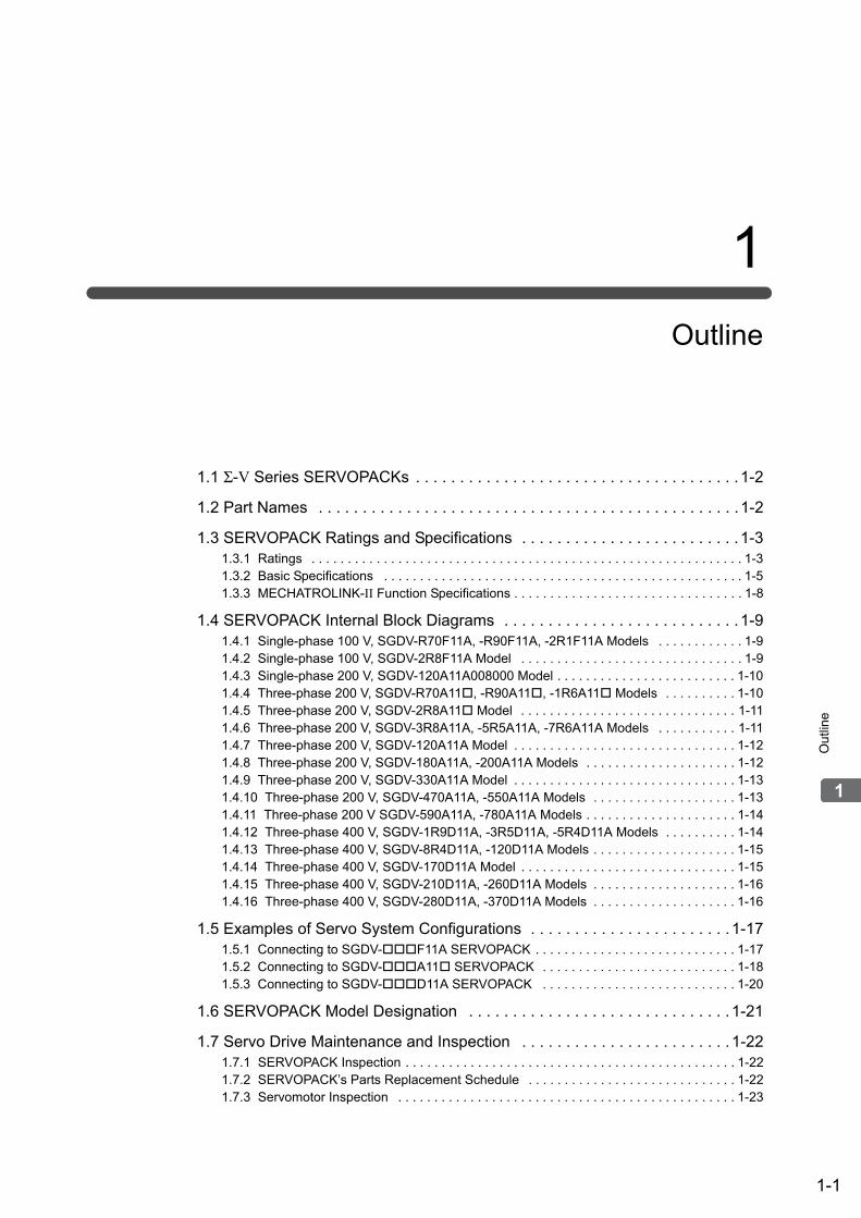
Chapter 1 Outline . . . . . . . . . . . . . . . . . . . . . . . . . . . . . . . . . . . . . . . . . . . .1-1
1.1 Σ-V Series SERVOPACKs . . . . . . . . . . . . . . . . . . . . . . . . . . . . . . . . . . . . . . . 1-21.2 Part Names . . . . . . . . . . . . . . . . . . . . . . . . . . . . . . . . . . . . . . . . . . . . . . . . . . 1-21.3 SERVOPACK Ratings and Specifications . . . . . . . . . . . . . . . . . . . . . . . . . . . 1-3
1.3.1 Ratings . . . . . . . . . . . . . . . . . . . . . . . . . . . . . . . . . . . . . . . . . . . . . . . . . . . . . . . . . . . . . . . . 1-31.3.2 Basic Specifications . . . . . . . . . . . . . . . . . . . . . . . . . . . . . . . . . . . . . . . . . . . . . . . . . . . . . . 1-51.3.3 MECHATROLINK-II Function Specifications . . . . . . . . . . . . . . . . . . . . . . . . . . . . . . . . . . . 1-8
1.4 SERVOPACK Internal Block Diagrams . . . . . . . . . . . . . . . . . . . . . . . . . . . . . 1-91.4.1 Single-phase 100 V, SGDV-R70F11A, -R90F11A, -2R1F11A Models . . . . . . . . . . . . . . . . 1-91.4.2 Single-phase 100 V, SGDV-2R8F11A Model . . . . . . . . . . . . . . . . . . . . . . . . . . . . . . . . . . . 1-91.4.3 Single-phase 200 V, SGDV-120A11A008000 Model . . . . . . . . . . . . . . . . . . . . . . . . . . . . 1-101.4.4 Three-phase 200 V, SGDV-R70A11, -R90A11, -1R6A11 Models. . . . . . . . . . . . . . 1-101.4.5 Three-phase 200 V, SGDV-2R8A11 Model. . . . . . . . . . . . . . . . . . . . . . . . . . . . . . . . . . 1-111.4.6 Three-phase 200 V, SGDV-3R8A11A, -5R5A11A, -7R6A11A Models . . . . . . . . . . . . . . . 1-111.4.7 Three-phase 200 V, SGDV-120A11A Model . . . . . . . . . . . . . . . . . . . . . . . . . . . . . . . . . . 1-121.4.8 Three-phase 200 V, SGDV-180A11A, -200A11A Models. . . . . . . . . . . . . . . . . . . . . . . . . 1-121.4.9 Three-phase 200 V, SGDV-330A11A Model . . . . . . . . . . . . . . . . . . . . . . . . . . . . . . . . . . 1-131.4.10 Three-phase 200 V, SGDV-470A11A, -550A11A Models. . . . . . . . . . . . . . . . . . . . . . . . 1-131.4.11 Three-phase 200 V SGDV-590A11A, -780A11A Models . . . . . . . . . . . . . . . . . . . . . . . . 1-141.4.12 Three-phase 400 V, SGDV-1R9D11A, -3R5D11A, -5R4D11A Models. . . . . . . . . . . . . . 1-141.4.13 Three-phase 400 V, SGDV-8R4D11A, -120D11A Models . . . . . . . . . . . . . . . . . . . . . . . 1-151.4.14 Three-phase 400 V, SGDV-170D11A Model . . . . . . . . . . . . . . . . . . . . . . . . . . . . . . . . . 1-151.4.15 Three-phase 400 V, SGDV-210D11A, -260D11A Models . . . . . . . . . . . . . . . . . . . . . . . 1-161.4.16 Three-phase 400 V, SGDV-280D11A, -370D11A Models . . . . . . . . . . . . . . . . . . . . . . . 1-16
1.5 Examples of Servo System Configurations . . . . . . . . . . . . . . . . . . . . . . . . . 1-171.5.1 Connecting to SGDV-F11A SERVOPACK . . . . . . . . . . . . . . . . . . . . . . . . . . . . . . . 1-171.5.2 Connecting to SGDV-A11 SERVOPACK. . . . . . . . . . . . . . . . . . . . . . . . . . . . . . . 1-181.5.3 Connecting to SGDV-D11A SERVOPACK . . . . . . . . . . . . . . . . . . . . . . . . . . . . . . . 1-20
1.6 SERVOPACK Model Designation. . . . . . . . . . . . . . . . . . . . . . . . . . . . . . . . . 1-211.7 Servo Drive Maintenance and Inspection. . . . . . . . . . . . . . . . . . . . . . . . . . . 1-22
1.7.1 SERVOPACK Inspection . . . . . . . . . . . . . . . . . . . . . . . . . . . . . . . . . . . . . . . . . . . . . . . . . 1-221.7.2 SERVOPACK’s Parts Replacement Schedule . . . . . . . . . . . . . . . . . . . . . . . . . . . . . . . . . 1-221.7.3 Servomotor Inspection . . . . . . . . . . . . . . . . . . . . . . . . . . . . . . . . . . . . . . . . . . . . . . . . . . . 1-23
Chapter 2 Panel Display and Operation of Digital Operator . . . . . . . . . . . .2-1
2.1 Panel Display . . . . . . . . . . . . . . . . . . . . . . . . . . . . . . . . . . . . . . . . . . . . . . . . . 2-22.1.1 Status Display . . . . . . . . . . . . . . . . . . . . . . . . . . . . . . . . . . . . . . . . . . . . . . . . . . . . . . . . . . 2-22.1.2 Alarm and Warning Display . . . . . . . . . . . . . . . . . . . . . . . . . . . . . . . . . . . . . . . . . . . . . . . . 2-22.1.3 Hard Wire Base Block Display . . . . . . . . . . . . . . . . . . . . . . . . . . . . . . . . . . . . . . . . . . . . . . 2-22.1.4 Overtravel Display . . . . . . . . . . . . . . . . . . . . . . . . . . . . . . . . . . . . . . . . . . . . . . . . . . . . . . . 2-2
2.2 Operation of Digital Operator . . . . . . . . . . . . . . . . . . . . . . . . . . . . . . . . . . . . . 2-32.3 Utility Functions (Fn) . . . . . . . . . . . . . . . . . . . . . . . . . . . . . . . . . . . . . . . 2-32.4 Parameters (Pn) . . . . . . . . . . . . . . . . . . . . . . . . . . . . . . . . . . . . . . . . . . 2-4
2.4.1 Parameter Classification . . . . . . . . . . . . . . . . . . . . . . . . . . . . . . . . . . . . . . . . . . . . . . . . . . 2-42.4.2 Notation for Parameters . . . . . . . . . . . . . . . . . . . . . . . . . . . . . . . . . . . . . . . . . . . . . . . . . . . 2-42.4.3 Setting Parameters . . . . . . . . . . . . . . . . . . . . . . . . . . . . . . . . . . . . . . . . . . . . . . . . . . . . . . 2-5
2.5 Monitor Displays (Un) . . . . . . . . . . . . . . . . . . . . . . . . . . . . . . . . . . . . . . 2-7

xvii
Chapter 3 Wiring and Connection . . . . . . . . . . . . . . . . . . . . . . . . . . . . . . . .3-1
3.1 Main Circuit Wiring. . . . . . . . . . . . . . . . . . . . . . . . . . . . . . . . . . . . . . . . . . . . . 3-23.1.1 Main Circuit Terminals . . . . . . . . . . . . . . . . . . . . . . . . . . . . . . . . . . . . . . . . . . . . . . . . . . . . 3-23.1.2 Using a Standard Power Supply
(Single-phase 100 V, Three-phase 200 V, or Three-phase 400 V) . . . . . . . . . . . . . . . . . . 3-33.1.3 Using the SERVOPACK with Single-phase, 200 V Power Input . . . . . . . . . . . . . . . . . . . 3-113.1.4 Using the SERVOPACK with a DC Power Input . . . . . . . . . . . . . . . . . . . . . . . . . . . . . . . 3-143.1.5 Using More Than One SERVOPACK. . . . . . . . . . . . . . . . . . . . . . . . . . . . . . . . . . . . . . . . 3-163.1.6 General Precautions for Wiring . . . . . . . . . . . . . . . . . . . . . . . . . . . . . . . . . . . . . . . . . . . . 3-17
3.2 I/O Signal Connections . . . . . . . . . . . . . . . . . . . . . . . . . . . . . . . . . . . . . . . . 3-183.2.1 I/O Signal (CN1) Names and Functions. . . . . . . . . . . . . . . . . . . . . . . . . . . . . . . . . . . . . . 3-183.2.2 Safety Function Signal (CN8) Names and Functions. . . . . . . . . . . . . . . . . . . . . . . . . . . . 3-193.2.3 Example of I/O Signal Connections . . . . . . . . . . . . . . . . . . . . . . . . . . . . . . . . . . . . . . . . . 3-20
3.3 I/O Signal Allocations. . . . . . . . . . . . . . . . . . . . . . . . . . . . . . . . . . . . . . . . . . 3-213.3.1 Input Signal Allocations . . . . . . . . . . . . . . . . . . . . . . . . . . . . . . . . . . . . . . . . . . . . . . . . . . 3-213.3.2 Output Signal Allocations . . . . . . . . . . . . . . . . . . . . . . . . . . . . . . . . . . . . . . . . . . . . . . . . . 3-23
3.4 Examples of Connection to Host Controller . . . . . . . . . . . . . . . . . . . . . . . . . 3-243.4.1 Sequence Input Circuit . . . . . . . . . . . . . . . . . . . . . . . . . . . . . . . . . . . . . . . . . . . . . . . . . . . 3-243.4.2 Sequence Output Circuit . . . . . . . . . . . . . . . . . . . . . . . . . . . . . . . . . . . . . . . . . . . . . . . . . 3-25
3.5 Wiring MECHATROLINK-II Communications . . . . . . . . . . . . . . . . . . . . . . . 3-273.6 Encoder Connection . . . . . . . . . . . . . . . . . . . . . . . . . . . . . . . . . . . . . . . . . . 3-28
3.6.1 Encoder Signal (CN2) Names and Functions . . . . . . . . . . . . . . . . . . . . . . . . . . . . . . . . . 3-283.6.2 Encoder Connection Examples . . . . . . . . . . . . . . . . . . . . . . . . . . . . . . . . . . . . . . . . . . . . 3-28
3.7 Connecting Regenerative Resistors . . . . . . . . . . . . . . . . . . . . . . . . . . . . . . 3-303.7.1 Connecting Regenerative Resistors. . . . . . . . . . . . . . . . . . . . . . . . . . . . . . . . . . . . . . . . . 3-303.7.2 Setting Regenerative Resistor Capacity. . . . . . . . . . . . . . . . . . . . . . . . . . . . . . . . . . . . . . 3-32
3.8 Noise Control and Measures for Harmonic Suppression. . . . . . . . . . . . . . . 3-333.8.1 Wiring for Noise Control . . . . . . . . . . . . . . . . . . . . . . . . . . . . . . . . . . . . . . . . . . . . . . . . . . 3-333.8.2 Precautions on Connecting Noise Filter. . . . . . . . . . . . . . . . . . . . . . . . . . . . . . . . . . . . . . 3-353.8.3 Connecting a Reactor for Harmonic Suppression . . . . . . . . . . . . . . . . . . . . . . . . . . . . . . 3-36
Chapter 4 Operation . . . . . . . . . . . . . . . . . . . . . . . . . . . . . . . . . . . . . . . . . .4-1
4.1 MECHATROLINK-II Communications Settings . . . . . . . . . . . . . . . . . . . . . . . 4-34.1.1 Setting the Communications Specifications . . . . . . . . . . . . . . . . . . . . . . . . . . . . . . . . . . . . 4-34.1.2 Setting the Station Address . . . . . . . . . . . . . . . . . . . . . . . . . . . . . . . . . . . . . . . . . . . . . . . . 4-4
4.2 MECHATROLINK-II Commands . . . . . . . . . . . . . . . . . . . . . . . . . . . . . . . . . . 4-44.3 Basic Functions Settings . . . . . . . . . . . . . . . . . . . . . . . . . . . . . . . . . . . . . . . . 4-5
4.3.1 Servomotor Rotation Direction . . . . . . . . . . . . . . . . . . . . . . . . . . . . . . . . . . . . . . . . . . . . . .4-54.3.2 Overtravel. . . . . . . . . . . . . . . . . . . . . . . . . . . . . . . . . . . . . . . . . . . . . . . . . . . . . . . . . . . . . . 4-64.3.3 Software Limit Settings. . . . . . . . . . . . . . . . . . . . . . . . . . . . . . . . . . . . . . . . . . . . . . . . . . . . 4-94.3.4 Holding Brakes. . . . . . . . . . . . . . . . . . . . . . . . . . . . . . . . . . . . . . . . . . . . . . . . . . . . . . . . . 4-104.3.5 Stopping Servomotors after SV_OFF Command or Alarm Occurrence. . . . . . . . . . . . . . 4-154.3.6 Instantaneous Power Interruption Settings . . . . . . . . . . . . . . . . . . . . . . . . . . . . . . . . . . . 4-174.3.7 SEMI F47 Function
(Torque Limit Function for Low DC Power Supply Voltage for Main Circuit) . . . . . . . . . . 4-184.3.8 Setting Motor Overload Detection Level . . . . . . . . . . . . . . . . . . . . . . . . . . . . . . . . . . . . . 4-21
4.4 Trial Operation . . . . . . . . . . . . . . . . . . . . . . . . . . . . . . . . . . . . . . . . . . . . . . . 4-234.4.1 Inspection and Checking before Trial Operation . . . . . . . . . . . . . . . . . . . . . . . . . . . . . . . 4-234.4.2 Trial Operation via MECHATROLINK-II . . . . . . . . . . . . . . . . . . . . . . . . . . . . . . . . . . . . . . 4-244.4.3 Electronic Gear . . . . . . . . . . . . . . . . . . . . . . . . . . . . . . . . . . . . . . . . . . . . . . . . . . . . . . . . 4-254.4.4 Encoder Output Pulses . . . . . . . . . . . . . . . . . . . . . . . . . . . . . . . . . . . . . . . . . . . . . . . . . . 4-274.4.5 Setting Encoder Output Pulse . . . . . . . . . . . . . . . . . . . . . . . . . . . . . . . . . . . . . . . . . . . . . 4-28
4.5 Test Without Motor Function . . . . . . . . . . . . . . . . . . . . . . . . . . . . . . . . . . . . 4-294.5.1 Motor Information . . . . . . . . . . . . . . . . . . . . . . . . . . . . . . . . . . . . . . . . . . . . . . . . . . . . . . . 4-294.5.2 Motor Position and Speed Responses . . . . . . . . . . . . . . . . . . . . . . . . . . . . . . . . . . . . . . . 4-304.5.3 Limitations . . . . . . . . . . . . . . . . . . . . . . . . . . . . . . . . . . . . . . . . . . . . . . . . . . . . . . . . . . . . 4-314.5.4 Digital Operator Displays during Testing without Motor . . . . . . . . . . . . . . . . . . . . . . . . . . 4-32

xviii
4.6 Limiting Torque . . . . . . . . . . . . . . . . . . . . . . . . . . . . . . . . . . . . . . . . . . . . . . . 4-334.6.1 Internal Torque Limit. . . . . . . . . . . . . . . . . . . . . . . . . . . . . . . . . . . . . . . . . . . . . . . . . . . . . 4-334.6.2 External Torque Limit . . . . . . . . . . . . . . . . . . . . . . . . . . . . . . . . . . . . . . . . . . . . . . . . . . . . 4-344.6.3 Checking Output Torque Limiting during Operation . . . . . . . . . . . . . . . . . . . . . . . . . . . . . 4-35
4.7 Absolute Encoders . . . . . . . . . . . . . . . . . . . . . . . . . . . . . . . . . . . . . . . . . . . . 4-364.7.1 Connecting the Absolute Encoder . . . . . . . . . . . . . . . . . . . . . . . . . . . . . . . . . . . . . . . . . . 4-374.7.2 Absolute Data Request (SENS ON Command) . . . . . . . . . . . . . . . . . . . . . . . . . . . . . . . . 4-394.7.3 Battery Replacement . . . . . . . . . . . . . . . . . . . . . . . . . . . . . . . . . . . . . . . . . . . . . . . . . . . . 4-404.7.4 Absolute Encoder Setup and Reinitialization . . . . . . . . . . . . . . . . . . . . . . . . . . . . . . . . . . 4-424.7.5 Absolute Data Reception Sequence . . . . . . . . . . . . . . . . . . . . . . . . . . . . . . . . . . . . . . . . 4-434.7.6 Multiturn Limit Setting. . . . . . . . . . . . . . . . . . . . . . . . . . . . . . . . . . . . . . . . . . . . . . . . . . . . 4-484.7.7 Multiturn Limit Disagreement Alarm (A.CC0) . . . . . . . . . . . . . . . . . . . . . . . . . . . . . . . . . . 4-494.7.8 Absolute Encoder Origin Offset . . . . . . . . . . . . . . . . . . . . . . . . . . . . . . . . . . . . . . . . . . . . 4-50
4.8 Other Output Signals . . . . . . . . . . . . . . . . . . . . . . . . . . . . . . . . . . . . . . . . . . 4-514.8.1 Servo Alarm Output Signal (ALM) . . . . . . . . . . . . . . . . . . . . . . . . . . . . . . . . . . . . . . . . . . 4-514.8.2 Warning Output Signal (/WARN) . . . . . . . . . . . . . . . . . . . . . . . . . . . . . . . . . . . . . . . . . . . 4-514.8.3 Rotation Detection Output Signal (/TGON) . . . . . . . . . . . . . . . . . . . . . . . . . . . . . . . . . . . 4-524.8.4 Servo Ready Output Signal (/S-RDY) . . . . . . . . . . . . . . . . . . . . . . . . . . . . . . . . . . . . . . . 4-524.8.5 Speed Coincidence Output Signal (/V-CMP) . . . . . . . . . . . . . . . . . . . . . . . . . . . . . . . . . . 4-534.8.6 Positioning Completed Output Signal (/COIN) . . . . . . . . . . . . . . . . . . . . . . . . . . . . . . . . . 4-544.8.7 Positioning Near Output Signal (/NEAR) . . . . . . . . . . . . . . . . . . . . . . . . . . . . . . . . . . . . . 4-554.8.8 Speed Limit Detection Signal (/VLT) . . . . . . . . . . . . . . . . . . . . . . . . . . . . . . . . . . . . . . . . 4-56
4.9 Safety Function . . . . . . . . . . . . . . . . . . . . . . . . . . . . . . . . . . . . . . . . . . . . . . 4-584.9.1 Hard Wire Base Block (HWBB) Function . . . . . . . . . . . . . . . . . . . . . . . . . . . . . . . . . . . . . 4-584.9.2 External Device Monitor (EDM1) . . . . . . . . . . . . . . . . . . . . . . . . . . . . . . . . . . . . . . . . . . . 4-644.9.3 Application Example of Safety Functions. . . . . . . . . . . . . . . . . . . . . . . . . . . . . . . . . . . . . 4-664.9.4 Confirming Safety Functions . . . . . . . . . . . . . . . . . . . . . . . . . . . . . . . . . . . . . . . . . . . . . . 4-674.9.5 Safety Device Connections . . . . . . . . . . . . . . . . . . . . . . . . . . . . . . . . . . . . . . . . . . . . . . . 4-684.9.6 Precautions for Safety Functions . . . . . . . . . . . . . . . . . . . . . . . . . . . . . . . . . . . . . . . . . . . 4-69
Chapter 5 Adjustments . . . . . . . . . . . . . . . . . . . . . . . . . . . . . . . . . . . . . . . .5-1
5.1 Type of Adjustments and Basic Adjustment Procedure . . . . . . . . . . . . . . . . . 5-35.1.1 Adjustments . . . . . . . . . . . . . . . . . . . . . . . . . . . . . . . . . . . . . . . . . . . . . . . . . . . . . . . . . . . . 5-35.1.2 Basic Adjustment Procedure . . . . . . . . . . . . . . . . . . . . . . . . . . . . . . . . . . . . . . . . . . . . . . . 5-45.1.3 Monitoring Operation during Adjustment . . . . . . . . . . . . . . . . . . . . . . . . . . . . . . . . . . . . . . 5-55.1.4 Safety Precautions on Adjustment of Servo Gains . . . . . . . . . . . . . . . . . . . . . . . . . . . . . . 5-8
5.2 Tuning-less Function . . . . . . . . . . . . . . . . . . . . . . . . . . . . . . . . . . . . . . . . . . 5-115.2.1 Tuning-less Function . . . . . . . . . . . . . . . . . . . . . . . . . . . . . . . . . . . . . . . . . . . . . . . . . . . . 5-115.2.2 Tuning-less Levels Setting (Fn200) Procedure . . . . . . . . . . . . . . . . . . . . . . . . . . . . . . . . 5-145.2.3 Related Parameters . . . . . . . . . . . . . . . . . . . . . . . . . . . . . . . . . . . . . . . . . . . . . . . . . . . . . 5-16
5.3 Advanced Autotuning (Fn201) . . . . . . . . . . . . . . . . . . . . . . . . . . . . . . . . . . . 5-175.3.1 Advanced Autotuning . . . . . . . . . . . . . . . . . . . . . . . . . . . . . . . . . . . . . . . . . . . . . . . . . . . . 5-175.3.2 Advanced Autotuning Procedure . . . . . . . . . . . . . . . . . . . . . . . . . . . . . . . . . . . . . . . . . . 5-205.3.3 Related Parameters . . . . . . . . . . . . . . . . . . . . . . . . . . . . . . . . . . . . . . . . . . . . . . . . . . . . . 5-26
5.4 Advanced Autotuning by Reference (Fn202) . . . . . . . . . . . . . . . . . . . . . . . . 5-275.4.1 Advanced Autotuning by Reference. . . . . . . . . . . . . . . . . . . . . . . . . . . . . . . . . . . . . . . . . 5-275.4.2 Advanced Autotuning by Reference Procedure . . . . . . . . . . . . . . . . . . . . . . . . . . . . . . . 5-305.4.3 Related Parameters . . . . . . . . . . . . . . . . . . . . . . . . . . . . . . . . . . . . . . . . . . . . . . . . . . . . . 5-34
5.5 One-parameter Tuning (Fn203) . . . . . . . . . . . . . . . . . . . . . . . . . . . . . . . . . . 5-355.5.1 One-parameter Tuning . . . . . . . . . . . . . . . . . . . . . . . . . . . . . . . . . . . . . . . . . . . . . . . . . . . 5-355.5.2 One-parameter Tuning Procedure . . . . . . . . . . . . . . . . . . . . . . . . . . . . . . . . . . . . . . . . . . 5-375.5.3 One-parameter Tuning Example . . . . . . . . . . . . . . . . . . . . . . . . . . . . . . . . . . . . . . . . . . . 5-435.5.4 Related Parameters . . . . . . . . . . . . . . . . . . . . . . . . . . . . . . . . . . . . . . . . . . . . . . . . . . . . . 5-45
5.6 Anti-Resonance Control Adjustment Function (Fn204) . . . . . . . . . . . . . . . . 5-465.6.1 Anti-Resonance Control Adjustment Function . . . . . . . . . . . . . . . . . . . . . . . . . . . . . . . . . 5-465.6.2 Anti-Resonance Control Adjustment Function Operating Procedure. . . . . . . . . . . . . . . . 5-475.6.3 Related Parameters . . . . . . . . . . . . . . . . . . . . . . . . . . . . . . . . . . . . . . . . . . . . . . . . . . . . . 5-51

xix
5.7 Vibration Suppression Function (Fn205) . . . . . . . . . . . . . . . . . . . . . . . . . . . 5-525.7.1 Vibration Suppression Function . . . . . . . . . . . . . . . . . . . . . . . . . . . . . . . . . . . . . . . . . . . . 5-525.7.2 Vibration Suppression Function Operating Procedure . . . . . . . . . . . . . . . . . . . . . . . . . . . 5-535.7.3 Related Parameters . . . . . . . . . . . . . . . . . . . . . . . . . . . . . . . . . . . . . . . . . . . . . . . . . . . . . 5-56
5.8 Additional Adjustment Function . . . . . . . . . . . . . . . . . . . . . . . . . . . . . . . . . . 5-575.8.1 Switching Gain Settings . . . . . . . . . . . . . . . . . . . . . . . . . . . . . . . . . . . . . . . . . . . . . . . . . . 5-575.8.2 Manual Adjustment of Friction Compensation . . . . . . . . . . . . . . . . . . . . . . . . . . . . . . . . . 5-615.8.3 Current Control Mode Selection Function . . . . . . . . . . . . . . . . . . . . . . . . . . . . . . . . . . . . 5-635.8.4 Current Gain Level Setting. . . . . . . . . . . . . . . . . . . . . . . . . . . . . . . . . . . . . . . . . . . . . . . . 5-635.8.5 Speed Detection Method Selection . . . . . . . . . . . . . . . . . . . . . . . . . . . . . . . . . . . . . . . . . 5-635.8.6 Backlash Compensation Function . . . . . . . . . . . . . . . . . . . . . . . . . . . . . . . . . . . . . . . . . . 5-64
5.9 Compatible Adjustment Function . . . . . . . . . . . . . . . . . . . . . . . . . . . . . . . . . 5-705.9.1 Feedforward Reference . . . . . . . . . . . . . . . . . . . . . . . . . . . . . . . . . . . . . . . . . . . . . . . . . .5-705.9.2 Mode Switch (P/PI Switching) . . . . . . . . . . . . . . . . . . . . . . . . . . . . . . . . . . . . . . . . . . . . . 5-715.9.3 Torque Reference Filter . . . . . . . . . . . . . . . . . . . . . . . . . . . . . . . . . . . . . . . . . . . . . . . . . . 5-735.9.4 Position Integral . . . . . . . . . . . . . . . . . . . . . . . . . . . . . . . . . . . . . . . . . . . . . . . . . . . . . . . . 5-75
Chapter 6 Utility Functions (Fn) . . . . . . . . . . . . . . . . . . . . . . . . . . . . .6-1
6.1 List of Utility Functions . . . . . . . . . . . . . . . . . . . . . . . . . . . . . . . . . . . . . . . . . . 6-26.2 Alarm History Display (Fn000) . . . . . . . . . . . . . . . . . . . . . . . . . . . . . . . . . . . . 6-36.3 JOG Operation (Fn002) . . . . . . . . . . . . . . . . . . . . . . . . . . . . . . . . . . . . . . . . . 6-46.4 Origin Search (Fn003) . . . . . . . . . . . . . . . . . . . . . . . . . . . . . . . . . . . . . . . . . . 6-66.5 Program JOG Operation (Fn004) . . . . . . . . . . . . . . . . . . . . . . . . . . . . . . . . . 6-86.6 Initializing Parameter Settings (Fn005) . . . . . . . . . . . . . . . . . . . . . . . . . . . . 6-126.7 Clearing Alarm History (Fn006) . . . . . . . . . . . . . . . . . . . . . . . . . . . . . . . . . . 6-136.8 Offset Adjustment of Analog Monitor Output (Fn00C) . . . . . . . . . . . . . . . . . 6-146.9 Gain Adjustment of Analog Monitor Output (Fn00D) . . . . . . . . . . . . . . . . . . 6-166.10 Automatic Offset-Signal Adjustment of the Motor Current Detection Signal
(Fn00E) . . . . . . . . . . . . . . . . . . . . . . . . . . . . . . . . . . . . . . . . . . . . . . . . . . . . 6-186.11 Manual Offset-Signal Adjustment of the Motor Current Detection Signal
(Fn00F) . . . . . . . . . . . . . . . . . . . . . . . . . . . . . . . . . . . . . . . . . . . . . . . . . . . . 6-196.12 Write Prohibited Setting (Fn010) . . . . . . . . . . . . . . . . . . . . . . . . . . . . . . . . 6-216.13 Servomotor Model Display (Fn011) . . . . . . . . . . . . . . . . . . . . . . . . . . . . . . 6-236.14 Software Version Display (Fn012) . . . . . . . . . . . . . . . . . . . . . . . . . . . . . . . 6-246.15 Resetting Configuration Errors in Option Modules (Fn014) . . . . . . . . . . . . 6-256.16 Vibration Detection Level Initialization (Fn01B) . . . . . . . . . . . . . . . . . . . . . 6-266.17 Display of SERVOPACK and Servomotor ID (Fn01E) . . . . . . . . . . . . . . . . 6-286.18 Display of Servomotor ID in Feedback Option Module (Fn01F) . . . . . . . . 6-306.19 Origin Setting (Fn020) . . . . . . . . . . . . . . . . . . . . . . . . . . . . . . . . . . . . . . . . 6-316.20 Software Reset (Fn030). . . . . . . . . . . . . . . . . . . . . . . . . . . . . . . . . . . . . . . 6-326.21 EasyFFT (Fn206). . . . . . . . . . . . . . . . . . . . . . . . . . . . . . . . . . . . . . . . . . . . 6-336.22 Online Vibration Monitor (Fn207). . . . . . . . . . . . . . . . . . . . . . . . . . . . . . . . 6-37
Chapter 7 Monitor Displays (Un) . . . . . . . . . . . . . . . . . . . . . . . . . . . .7-1
7.1 List of Monitor Displays . . . . . . . . . . . . . . . . . . . . . . . . . . . . . . . . . . . . . . . . . 7-27.2 Viewing Monitor Displays. . . . . . . . . . . . . . . . . . . . . . . . . . . . . . . . . . . . . . . . 7-37.3 Monitoring Input Signals . . . . . . . . . . . . . . . . . . . . . . . . . . . . . . . . . . . . . . . . 7-4
7.3.1 Interpreting Input Signal Display Status . . . . . . . . . . . . . . . . . . . . . . . . . . . . . . . . . . . . . . . 7-47.3.2 Input Signal Display Example . . . . . . . . . . . . . . . . . . . . . . . . . . . . . . . . . . . . . . . . . . . . . .7-5

xx
7.4 Monitoring Output Signals . . . . . . . . . . . . . . . . . . . . . . . . . . . . . . . . . . . . . . . 7-67.4.1 Interpreting Output Signal Display Status . . . . . . . . . . . . . . . . . . . . . . . . . . . . . . . . . . . . . 7-67.4.2 Output Signal Display Example . . . . . . . . . . . . . . . . . . . . . . . . . . . . . . . . . . . . . . . . . . . . . 7-6
7.5 Monitoring Safety Input Signals . . . . . . . . . . . . . . . . . . . . . . . . . . . . . . . . . . . 7-77.5.1 Interpreting Safety Input Signal Display Status . . . . . . . . . . . . . . . . . . . . . . . . . . . . . . . . . 7-77.5.2 Safety Input Signal Display Example . . . . . . . . . . . . . . . . . . . . . . . . . . . . . . . . . . . . . . . . . 7-7
Chapter 8 Fully-closed Loop Control. . . . . . . . . . . . . . . . . . . . . . . . . . . . . .8-1
8.1 System Configuration and Connection Examplefor SERVOPACK with Fully-closed Loop Control. . . . . . . . . . . . . . . . . . . . . . 8-2
8.1.1 System Configuration. . . . . . . . . . . . . . . . . . . . . . . . . . . . . . . . . . . . . . . . . . . . . . . . . . . . . 8-28.1.2 Internal Block Diagram of Fully-closed Loop Control . . . . . . . . . . . . . . . . . . . . . . . . . . . . . 8-38.1.3 Serial Converter Unit . . . . . . . . . . . . . . . . . . . . . . . . . . . . . . . . . . . . . . . . . . . . . . . . . . . . . 8-48.1.4 Example of Connections to External Encoders . . . . . . . . . . . . . . . . . . . . . . . . . . . . . . . . . 8-68.1.5 Encoder Output Pulse Signals from SERVOPACK with an External Encoder
by Renishaw plc. . . . . . . . . . . . . . . . . . . . . . . . . . . . . . . . . . . . . . . . . . . . . . . . . . . . . . . . . 8-78.1.6 Precautions When Using an External Incremental Encoder by Magnescale . . . . . . . . . . . 8-8
8.2 SERVOPACK Startup Procedure . . . . . . . . . . . . . . . . . . . . . . . . . . . . . . . . . 8-128.3 Parameter Settings for Fully-closed Loop Control . . . . . . . . . . . . . . . . . . . . 8-14
8.3.1 Motor Rotation Direction . . . . . . . . . . . . . . . . . . . . . . . . . . . . . . . . . . . . . . . . . . . . . . . . . 8-158.3.2 Sine Wave Pitch (Frequency) for an External Encoder . . . . . . . . . . . . . . . . . . . . . . . . . . 8-178.3.3 Setting Encoder Output Pulses (PAO, PBO, and PCO). . . . . . . . . . . . . . . . . . . . . . . . . . 8-178.3.4 External Absolute Encoder Data Reception Sequence . . . . . . . . . . . . . . . . . . . . . . . . . . 8-188.3.5 Electronic Gear . . . . . . . . . . . . . . . . . . . . . . . . . . . . . . . . . . . . . . . . . . . . . . . . . . . . . . . . 8-218.3.6 Alarm Detection . . . . . . . . . . . . . . . . . . . . . . . . . . . . . . . . . . . . . . . . . . . . . . . . . . . . . . . . 8-228.3.7 Analog Monitor Signal . . . . . . . . . . . . . . . . . . . . . . . . . . . . . . . . . . . . . . . . . . . . . . . . . . . 8-238.3.8 Speed Feedback Method during Fully-closed Loop Control . . . . . . . . . . . . . . . . . . . . . . 8-23
Chapter 9 Troubleshooting . . . . . . . . . . . . . . . . . . . . . . . . . . . . . . . . . . . . .9-1
9.1 Alarm Displays . . . . . . . . . . . . . . . . . . . . . . . . . . . . . . . . . . . . . . . . . . . . . . . . 9-29.1.1 List of Alarms . . . . . . . . . . . . . . . . . . . . . . . . . . . . . . . . . . . . . . . . . . . . . . . . . . . . . . . . . . . 9-29.1.2 Troubleshooting of Alarms . . . . . . . . . . . . . . . . . . . . . . . . . . . . . . . . . . . . . . . . . . . . . . . . . 9-6
9.2 Warning Displays . . . . . . . . . . . . . . . . . . . . . . . . . . . . . . . . . . . . . . . . . . . . . 9-239.2.1 List of Warnings . . . . . . . . . . . . . . . . . . . . . . . . . . . . . . . . . . . . . . . . . . . . . . . . . . . . . . . . 9-239.2.2 Troubleshooting of Warnings . . . . . . . . . . . . . . . . . . . . . . . . . . . . . . . . . . . . . . . . . . . . . . 9-24
9.3 Monitoring Communication Data on Occurrence of an Alarm or Warning . . 9-289.4 Troubleshooting Malfunction Based on Operation
and Conditions of the Servomotor . . . . . . . . . . . . . . . . . . . . . . . . . . . . . . . . 9-29
Chapter 10 Appendix. . . . . . . . . . . . . . . . . . . . . . . . . . . . . . . . . . . . . . . . .10-1
10.1 List of Parameters . . . . . . . . . . . . . . . . . . . . . . . . . . . . . . . . . . . . . . . . . . . 10-210.2 Parameter Recording Table . . . . . . . . . . . . . . . . . . . . . . . . . . . . . . . . . . . 10-33
Index. . . . . . . . . . . . . . . . . . . . . . . . . . . . . . . . . . . . . . . . . . . . . . . . . . . Index-1
Revision History
1-1
1O
utli
ne
1Outline
1.1 Σ-V Series SERVOPACKs . . . . . . . . . . . . . . . . . . . . . . . . . . . . . . . . . . . . .1-2
1.2 Part Names . . . . . . . . . . . . . . . . . . . . . . . . . . . . . . . . . . . . . . . . . . . . . . . .1-2
1.3 SERVOPACK Ratings and Specifications . . . . . . . . . . . . . . . . . . . . . . . . .1-31.3.1 Ratings . . . . . . . . . . . . . . . . . . . . . . . . . . . . . . . . . . . . . . . . . . . . . . . . . . . . . . . . . . . . 1-31.3.2 Basic Specifications . . . . . . . . . . . . . . . . . . . . . . . . . . . . . . . . . . . . . . . . . . . . . . . . . . 1-51.3.3 MECHATROLINK-II Function Specifications . . . . . . . . . . . . . . . . . . . . . . . . . . . . . . . . 1-8
1.4 SERVOPACK Internal Block Diagrams . . . . . . . . . . . . . . . . . . . . . . . . . . .1-91.4.1 Single-phase 100 V, SGDV-R70F11A, -R90F11A, -2R1F11A Models . . . . . . . . . . . . 1-91.4.2 Single-phase 100 V, SGDV-2R8F11A Model . . . . . . . . . . . . . . . . . . . . . . . . . . . . . . . 1-91.4.3 Single-phase 200 V, SGDV-120A11A008000 Model . . . . . . . . . . . . . . . . . . . . . . . . . 1-101.4.4 Three-phase 200 V, SGDV-R70A11, -R90A11, -1R6A11 Models . . . . . . . . . . 1-101.4.5 Three-phase 200 V, SGDV-2R8A11 Model . . . . . . . . . . . . . . . . . . . . . . . . . . . . . . 1-111.4.6 Three-phase 200 V, SGDV-3R8A11A, -5R5A11A, -7R6A11A Models . . . . . . . . . . . 1-111.4.7 Three-phase 200 V, SGDV-120A11A Model . . . . . . . . . . . . . . . . . . . . . . . . . . . . . . . 1-121.4.8 Three-phase 200 V, SGDV-180A11A, -200A11A Models . . . . . . . . . . . . . . . . . . . . . 1-121.4.9 Three-phase 200 V, SGDV-330A11A Model . . . . . . . . . . . . . . . . . . . . . . . . . . . . . . . 1-131.4.10 Three-phase 200 V, SGDV-470A11A, -550A11A Models . . . . . . . . . . . . . . . . . . . . 1-131.4.11 Three-phase 200 V SGDV-590A11A, -780A11A Models . . . . . . . . . . . . . . . . . . . . . 1-141.4.12 Three-phase 400 V, SGDV-1R9D11A, -3R5D11A, -5R4D11A Models . . . . . . . . . . 1-141.4.13 Three-phase 400 V, SGDV-8R4D11A, -120D11A Models . . . . . . . . . . . . . . . . . . . . 1-151.4.14 Three-phase 400 V, SGDV-170D11A Model . . . . . . . . . . . . . . . . . . . . . . . . . . . . . . 1-151.4.15 Three-phase 400 V, SGDV-210D11A, -260D11A Models . . . . . . . . . . . . . . . . . . . . 1-161.4.16 Three-phase 400 V, SGDV-280D11A, -370D11A Models . . . . . . . . . . . . . . . . . . . . 1-16
1.5 Examples of Servo System Configurations . . . . . . . . . . . . . . . . . . . . . . .1-171.5.1 Connecting to SGDV-F11A SERVOPACK . . . . . . . . . . . . . . . . . . . . . . . . . . . . 1-171.5.2 Connecting to SGDV-A11 SERVOPACK . . . . . . . . . . . . . . . . . . . . . . . . . . . 1-181.5.3 Connecting to SGDV-D11A SERVOPACK . . . . . . . . . . . . . . . . . . . . . . . . . . . 1-20
1.6 SERVOPACK Model Designation . . . . . . . . . . . . . . . . . . . . . . . . . . . . . . 1-21
1.7 Servo Drive Maintenance and Inspection . . . . . . . . . . . . . . . . . . . . . . . . 1-221.7.1 SERVOPACK Inspection . . . . . . . . . . . . . . . . . . . . . . . . . . . . . . . . . . . . . . . . . . . . . . 1-221.7.2 SERVOPACK’s Parts Replacement Schedule . . . . . . . . . . . . . . . . . . . . . . . . . . . . . 1-221.7.3 Servomotor Inspection . . . . . . . . . . . . . . . . . . . . . . . . . . . . . . . . . . . . . . . . . . . . . . . 1-23

1 Outline
1-2
1.1 Σ-V Series SERVOPACKsThe Σ-V Series SERVOPACKs are designed for applications that require frequent high-speed, high-pre-cision positioning. The SERVOPACK makes the most of machine performance in the shortest time possi-ble, thus contributing to improving productivity.
1.2 Part NamesThis section describes the part names of SGDV SERVOPACK for MECHATROLINK-II communications ref-erence.
CN5 Analog monitor connectorUsed to monitor motor speed, torquereference, and other values througha special cable (option).
Panel display
Connects external regenerative resistors.
Used for control power supply input.
Charge indicator
Front cover
CN3 Connector for digital operator
CN1 I/O signal connectorUsed to connect sequence I/O signals.
CN7 Connector for personal computer(USB Connector)
Communicates with a personal computer.Use the connection cable (model: JZSP-CVS06-02-E).
CN2 Encoder connectorConnects the encoder in the Servomotor.
Ground terminalBe sure to connect to protect against electrical shock.
Main circuit power supply terminalsUsed for main circuit power supply input.
Control power supply terminals
Servomotor terminalsConnects the main circuit cable for servomotor.
SERVOPACK model
Regenerative resistor connecting terminals
Input voltage
CN8 Connector for safety function devices
DC reactor terminals for harmonic suppressionConnects DC reactor for harmonic suppression.
With front cover open
Used to set MECHATROLINK-II communications.
Lights when the main circuit power supply is ON and stays lit as long as the internal capacitor remains charged. Therefore, do not touch the SERVOPACK even after the power supply is turned OFF if the indicator is lit.It may result in electric shock.
Serial number
Rotary switch (SW 1)Used to set the MECHATROLINK-IIstation address.
DIP switch (SW 2)
Indicates the servo status with a seven-segmentLED display.
Power LED indicator (POWER)Indicates that the control power is being supplied.
Communications LED indicator (COM)Indicates that data is being transmitted betweenthe SERVOPACK and the MECHATROLINK-IIsystem.
MECHATROLINK-II communications connectorsConnects MECHATROLINK-II -supported devices.
Nameplate (Found on side of SERVOPACK.)Indicates the SERVOPACK model and ratings.
Connects a safety function device.Note: When not using a safety function device, use the
SERVOPACK with the safety function’s jumper con-nector inserted (the factory default state).For the connecting method, refer to 3.2.2 Safety Function Signal (CN8) Names and Functions.For details on how to use the safety function, refer to 4.9 Safety Function.
Refer to 3.1 Main Circuit Wiring.
Refer to 4.1.1 Setting the Communications Spec-
Refer to 5.1.3 Monitoring Operation during Adjustment.
Refer to 4.1.1 Setting the Communications Spec-
Refer to 3.1 Main Circuit Wiring.
Refer to 3.7 Connecting Regenerative Resistors.
Refer to 3.8.3 Connecting a Reactor for Harmonic Suppression.
Refer to 3.1 Main Circuit Wiring.
Refer to 3.1 Main Circuit Wiring.
Refer to 3.6 Encoder Connection.
Refer to 3.2 I/O Signal Connections.
Refer to 3.5 Wiring MECHATROLINK-II Communi-cations.
Refer to 1.6 SERVOPACK Model Designation.
Refer to 2.1.1 Status Display.
Connects a digital operator (option, model: JUSP-OP05A-1-E) or a personal computer (RS422).Refer to Σ-V Series Product Catalog (No.: KAEP S800000 42) and Σ-V Series User’s Manual, Operation of Digital Operator (No.: SIEP S800000 55).

1.3 SERVOPACK Ratings and Specifications
1-3
1O
utli
ne
1.3 SERVOPACK Ratings and SpecificationsThis section describes the ratings and specifications of SERVOPACKs.
1.3.1 RatingsRatings of SERVOPACKs are as shown below.
(1) SGDV with Single-phase, 100-V Rating
∗ Refer to 3.7 Connecting Regenerative Resistors for details.
(2) SGDV with Single-phase, 200-V Rating
∗1. The official model number is SGDV-120A11A008000.∗2. Refer to 3.7 Connecting Regenerative Resistors for details.
(3) SGDV with Three-phase, 200-V Rating
∗ Refer to 3.7 Connecting Regenerative Resistors for details.
SGDV (Single Phase, 100 V) R70 R90 2R1 2R8
Continuous Output Current [Arms] 0.66 0.91 2.1 2.8
Instantaneous Max. Output Current [Arms] 2.1 2.9 6.5 9.3
Regenerative Resistor * None or external
Main Circuit Power Supply Single-phase, 100 to 115 VAC, +10% to -15%, 50/60 Hz
Control Power Supply Single-phase, 100 to 115 VAC, +10% to -15%, 50/60 Hz
Overvoltage Category III
SGDV (Single Phase, 200 V) 120 *1
Continuous Output Current [Arms] 11.6
Instantaneous Max. Output Current [Arms] 28
Regenerative Resistor *2 Built-in or external
Main Circuit Power Supply Single-phase, 220 to 230 VAC, +10% to -15%, 50/60 Hz
Control Power Supply Single-phase, 220 to 230 VAC, +10% to -15%, 50/60 Hz
Overvoltage Category III
SGDV (Three Phase, 200 V) R70 R90 1R6 2R8 3R8 5R5 7R6 120 180 200 330 470 550 590 780
Continuous Output Current [Arms] 0.66 0.91 1.6 2.8 3.8 5.5 7.6 11.6 18.5 19.6 32.9 46.9 54.7 58.6 78.0
Instantaneous Max. Output Current [Arms]
2.1 2.9 5.8 9.3 11.0 16.9 17 28 42 56 84 110 130 140 170
Regenerative Resistor * None or external Built-in or external External
Main Circuit Power Supply Three-phase, 200 to 230 VAC, +10% to -15%, 50/60 Hz
Control Power Supply Single-phase, 200 to 230 VAC, +10% to -15%, 50/60 Hz
Overvoltage Category III

1 Outline
1.3.1 Ratings
1-4
(4) SGDV with Three-phase, 400-V Rating
∗ Refer to 3.7 Connecting Regenerative Resistors for details.
SGDV (Three Phase, 400 V) 1R9 3R5 5R4 8R4 120 170 210 260 280 370
Continuous Output Current [Arms] 1.9 3.5 5.4 8.4 11.9 16.5 20.8 25.7 28.1 37.2
Instantaneous Max. Output Current [Arms]
5.5 8.5 14 20 28 42 55 65 70 85
Regenerative Resistor * Built-in or external External
Main Circuit Power Supply Three-phase, 380 to 480 VAC, +10% to -15%, 50/60 Hz
Control Power Supply 24 VDC ±15%
Overvoltage Category III

1.3 SERVOPACK Ratings and Specifications
1-5
1O
utli
ne
1.3.2 Basic SpecificationsBasic specifications of SERVOPACKs are shown below.
Drive Method Sine-wave current drive with PWM control of IGBT
FeedbackEncoder: 13-bit (incremental), 17-bit, 20-bit (incremental/absolute) Note: Only 13-bit feedback is possible for incremental encoders.
OperatingConditions
Ambient Operating Tem-perature 0°C to +55°C
Storage Temperature -20°C to +85°C
Ambient Humidity90% RH or less
With no freezing or condensation
Storage Humidity 90% RH or less
Vibration Resistance 4.9 m/s2
Shock Resistance 19.6 m/s2
Protection Class IP10 An environment that satisfies the following conditions.• Free of corrosive or flammable gases• Free of exposure to water, oil, or chemicals• Free of dust, salts, or iron dustPollution Degree 2
Altitude 1000 m or less
Others Free of static electricity, strong electromagnetic fields, magnetic fields or exposure to radioactivity
Harmonized StandardsUL508CEN 50178, EN 55011 Group 1 class A, EN 61000-6-2, EN 61800-3, EN 61800-5-1, EN 954-1, and IEC 61508-1 to 61508-4
MountingStandard: Base-mountedOptional: Rack-mounted or duct-ventilated
Perfor-mance
Speed Control Range 1:5000 (The lower limit of the speed control range must be lower than the point at which the rated torque does not cause the servomotor to stop.)
SpeedRegu-lation*1
LoadRegulation 0% to 100% load: ±0.01% max. (at rated speed)
VoltageRegulation Rated voltage ±10%: 0% (at rated speed)
Temperature Regulation 25 ± 25°C: ±0.1% max. (at rated speed)
Torque ControlTolerance (Repeatability)
±1%
Soft Start Time Setting*4 0 to 10 s (Can be set individually for acceleration and deceleration.)

1 Outline
1.3.2 Basic Specifications
1-6
I/OSignals
Encoder Output Pulse Phase A, B, C: line driver Encoder output pulse: any setting ratio (Refer to 4.4.5.)
Sequence Input
Input Signals which canbe allocated
Number of Channels 7 ch
Functions
• Homing deceleration switch (/DEC) • External latch (/EXT 1 to 3) • Forward run prohibited (P-OT), reverse run prohibited
(N-OT)• Forward external torque limit (/P-CL), reverse external
torque limit (/N-CL)Signal allocations can be performed, and positive and negative logic can be changed.
Sequence Output
Fixed Output Servo alarm (ALM) output
Output Signals which can be allocated
Number of Channels 3 ch
Functions
• Positioning completion (/COIN)• Speed coincidence detection (/V-CMP)• Rotation detection (/TGON)• Servo ready (/S-RDY)• Torque limit detection (/CLT)• Speed limit detection (/VLT)• Brake (/BK)• Warning (/WARN)• Near (/NEAR)Signal allocations can be performed, and positive and negative logic can be changed.
Communi-cations Function
RS422ACommu-nications (CN3)
InterfaceDigital operator (model: JUSP-OP05A-1-E)Personal computer (can be connected with SigmaWin+)
1:N Communica-tions
N = Up to 15 stations possible at RS422A
Axis Address Setting
Set by parameter
USBCommu-nications (CN7)
Interface Personal computer (can be connected with SigmaWin+)
Communica-tions Standard
Complies with standard USB1.1. (12 Mbps)
LED Display Panel display (seven-segment), CHARGE, POWER, and COM indicators
MECHATROLINK-II Communications Setting Switches
Rotary Switch (SW1) Position: 16 positions (Refer to 4.1.2)
DIP Switch (SW2) Number of pins: Four pins (Refer to 4.1.1)
Analog Monitor (CN5)
Number of points: 2Output voltage: ± 10VDC (linearity effective range ± 8 V)Resolution: 16 bitsAccuracy: ± 20 mV (Typ)Max. output current: ± 10 mASettling time (± 1%): 1.2 ms (Typ)
Dynamic Brake (DB)Activated when a servo alarm or overtraveling occurs or when the power supply for the main circuit or servomotor is OFF.
Regenerative Processing Included *2
Overtravel Prevention (OT) Dynamic brake stop, deceleration to a stop, or free run to a stop at P-OT or N-OT
Protective Function Overcurrent, overvoltage, insufficient voltage, overload, regeneration error, and so on.
Utility Function Gain adjustment, alarm history, JOG operation, origin search, and so on.
(cont’d)

1.3 SERVOPACK Ratings and Specifications
1-7
1O
utli
ne
∗1. Speed regulation by load regulation is defined as follows:
∗2. Refer to 1.3.1 Ratings for details on regenerative resistors.∗3. Perform risk assessment for the system and be sure that the safety requirements are fulfilled.∗4. Refer to 4.2.10 Velocity Control (VELCTRL: 3CH) in the Σ-V Series/DC Power Input Σ-V Series/Σ-V Series for
Large-Capacity Models User’s Manual MECHATROLINK-II Commands (Manual No.: SIEP S800000 54) for details on the soft start function.
Safety Function
Input /HWBB1, /HWBB2: Baseblock signal for power module
Output EDM1: Monitoring status of internal safety circuit (fixed output)
Standards *3 EN954 Category 3, IEC61508 SIL2
Option Module Fully-closed module, safety module
(cont’d)
Speed regulation =No-load motor speed Total load motor speed
Rated motor speed× 100%
-

1 Outline
1.3.3 MECHATROLINK-II Function Specifications
1-8
1.3.3 MECHATROLINK-II Function SpecificationsThe following table shows the specifications of MECHATROLINK-II.
Function Specifications
MECHATROLINK-II Communication
Communication Pro-tocol MECHATROLINK-II
Station Address41H to 5FH (Max. number of stations: 30)Can be selected by the combination of the rotary switch (SW1) and the DIP switch (SW2).
Baud Rate10 Mbps, 4 MbpsCan be selected by the DIP switch (SW2).
Transmission Cycle 250 μs, 0.5 to 4.0 ms (Multiples of 0.5 ms)
Number of Transmis-sion Bytes
17 bytes per station or 32 bytes per stationCan be selected by the DIP switch (SW2).
Reference Method
Control Method Position, speed, or torque control with MECHATROLINK-II communication
Reference InputMECHATROLINK-I, MECHATROLINK-II commands (sequence, motion, data setting/reference, monitoring, or adjustment)

1.4 SERVOPACK Internal Block Diagrams
1-9
1O
utli
ne
1.4 SERVOPACK Internal Block Diagrams
1.4.1 Single-phase 100 V, SGDV-R70F11A, -R90F11A, -2R1F11A Models
1.4.2 Single-phase 100 V, SGDV-2R8F11A Model
L1
B1/ B2
L2
L1C
L2C
U
V
W CHARGE M
ENC
Control power supply
Main circuit power supply
Control power supply
±12 V
+5 V
+17 V
Current sensor
Dynamic brake circuit
Servomotor
Gate drive
Voltage sensor
Voltage sensor
Varistor
Varistor
Gate drive overcurrent protector Temperature sensor Relay
drive
+12 V
Fan
+ –
+ –
+–
CN3 CN7 CN8
CN2
I/O
I/F
CN1
CN6A
CN6B
CN5
MECHATROLINK-II communications
CPU(Position/speedcalculation, etc.)
Panel display
Digital operator Personalcomputer
Signal for safety function
Encoder outputpulse
I/O signal
Analog monitoroutputASIC
(PWM control, etc.)
Analogvoltageconverter
L1
L2
L1C
L2C
B1/ B2
U
V
W CHARGE M
ENC
+12 V
±12 V
+5 V
+17 V
Control power supply
Current sensor
Dynamic brake circuit
Servomotor
Gate drive
Voltage sensor
Voltage sensor
Varistor
Varistor
Gate drive overcurrent protector Temperature
sensor Relay drive
Fan
+ –+ –
+ –
Control power supply
Main circuit power supply
CN3 CN7 CN8
CN2
I/O
I/F
CN1
CN6A
CN6B
CN5
MECHATROLINK-II communications
CPU(Position/speedcalculation, etc.)
Panel display
Digital operator Personalcomputer
Signal for safety function
Encoder outputpulse
Analog monitoroutputASIC
(PWM control, etc.)
Analogvoltageconverter
I/O signal

1 Outline
1.4.3 Single-phase 200 V, SGDV-120A11A008000 Model
1-10
1.4.3 Single-phase 200 V, SGDV-120A11A008000 Model
1.4.4 Three-phase 200 V, SGDV-R70A11, -R90A11, -1R6A11 Models
∗ The following SERVOPACKs do not have cooling fans: SGDV-B
L1
B1/ B2 B3
L2
1
2
L1C
L2C
U
V
W
ENC
M L3 CHARGE
+15 V × 4
±12 V+5 V
Current sensor
Dynamic brake circuit
Servomotor
Gate drive Voltage sensor
Overheat protector, overcurrent protector
Voltage sensor
Varistor
Varistor
Relay drive
Fan 2 Fan 1
Control power supply
±12 V ±12 V
+
–
+ –
Main circuit power supply
Control power supply
CN3 CN7 CN8
CN2
I/O
I/F
CN1
CN6A
CN6B
CN5
MECHATROLINK-II communications
CPU(Position/speedcalculation, etc.)
Panel display
Digital operator Personalcomputer
Signal for safety function
Encoder outputpulse
Analog monitoroutputASIC
(PWM control, etc.)
Analogvoltageconverter
I/O signal
L1
B1/ B2 B3
L2
L3
1
2
L1C
L2C
U
V
W
ENC
M CHARGE
+17 V
±12 V+5 V
Current sensor
Dynamic brake circuit
Servomotor
Gate drive
Voltage sensor
Voltage sensor
Varistor
Varistor
Gate drive overcurrent protector Temperature sensor
Relay drive
Control power supply
+ –
+ –
Main circuit power supply
Control power supply
Fan
+12 V
∗
CN3 CN7 CN8
CN2
I/O
I/F
CN1
CN6A
CN6B
CN5
MECHATROLINK-II communications
CPU(Position/speedcalculation, etc.)
Panel display
Digital operator Personalcomputer
Signal for safety function
Encoder outputpulse
Analog monitoroutputASIC
(PWM control, etc.)
Analogvoltageconverter
I/O signal

1.4 SERVOPACK Internal Block Diagrams
1-11
1O
utli
ne
1.4.5 Three-phase 200 V, SGDV-2R8A11 Model
∗ The following SERVOPACKs do not have cooling fans: SGDV-B
1.4.6 Three-phase 200 V, SGDV-3R8A11A, -5R5A11A, -7R6A11A Models
L1
B1/ B2 B3
L2
L3
1
2
L1C
L2C
U
V
W
ENC
M CHARGE
+17 V
±12 V+5 V
Current sensor
Dynamic brake circuit
Servomotor
Gate drive
Voltage sensor
Voltage sensor
Varistor
Varistor
Gate drive overcurrent protector Temperature sensor
Relay drive
Control power supply
+ –
+ –
Main circuit power supply
Control power supply
CN3 CN7 CN8
CN2
I/O
I/F
CN1
CN6A
CN6B
CN5
MECHATROLINK-II communications
CPU(Position/speedcalculation, etc.)
Panel display
Digital operator Personalcomputer
Signal for safety function
Encoder outputpulse
Analog monitoroutputASIC
(PWM control, etc.)
Analogvoltageconverter
I/O signal
Fan
+12 V
∗
L1
B1/ B2 B3
L2
L3 1
2
L1C
L2C
U
V
W
ENC
M CHARGE
+17 V
±12 V+5 V
Current sensor
Dynamicbrake circuit
Servomotor
Gate drive
Voltage sensor
Voltage sensor
Varistor
Varistor
Gate drive overcurrent protector Temperature sensor
Relay drive
Fan
Control power supply
±12 V
+ –
+ –Main circuit
power supply
Control power supply
CN3 CN7 CN8
CN2
I/O
I/F
CN1
CN6A
CN6B
CN5
MECHATROLINK-II communications
CPU(Position/speedcalculation, etc.)
Panel display
Digital operator Personalcomputer
Signal for safety function
Encoder outputpulse
Analog monitoroutputASIC
(PWM control, etc.)
Analogvoltageconverter
I/O signal

1 Outline
1.4.7 Three-phase 200 V, SGDV-120A11A Model
1-12
1.4.7 Three-phase 200 V, SGDV-120A11A Model
1.4.8 Three-phase 200 V, SGDV-180A11A, -200A11A Models
L1
B1/ B2 B3
L2
L3 1
2
L1C
L2C
U
V
W
ENC
M CHARGE
+15 V × 4
±12 V+5 V
Current sensor
Dynamic brake circuit
Servomotor
Gate drive
Overheat protector, overcurrent protector
Voltage sensor
Voltage sensor
Varistor
Varistor
Relay drive
Fan
Control power supply
±12 V
+ –
+ –Main circuit
power supply
Control power supply
CN3 CN7 CN8
CN2
I/O
I/F
CN1
CN6A
CN6B
CN5
MECHATROLINK-II communications
CPU(Position/speedcalculation, etc.)
Panel display
Digital operator Personalcomputer
Signal for safety function
Encoder outputpulse
Analog monitoroutputASIC
(PWM control, etc.)
Analogvoltageconverter
I/O signal
L1
B1/ B2 B3
L2
L3 1
2
L1C
L2C
U
V
W
ENC
M CHARGE
+
–
+15 V × 4
±12 V+5 V
Current sensor
Dynamic brake circuit
Servomotor
Gate drive Voltage sensor
Overheat protector, overcurrent protector
Voltage sensor
Varistor
Varistor
Relay drive
Fan 2 Fan 1
Control power supply
±12 V ±12 V
+ –
Main circuit power supply
Control power supply
CN3 CN7 CN8
CN2
I/O
I/F
CN1
CN6A
CN6B
CN5
MECHATROLINK-II communications
CPU(Position/speedcalculation, etc.)
Panel display
Digital operator Personalcomputer
Signal for safety function
Encoder outputpulse
Analog monitoroutputASIC
(PWM control, etc.)
Analogvoltageconverter
I/O signal

1.4 SERVOPACK Internal Block Diagrams
1-13
1O
utli
ne
1.4.9 Three-phase 200 V, SGDV-330A11A Model
1.4.10 Three-phase 200 V, SGDV-470A11A, -550A11A Models
L1
B1/ B2 B3
L2
L3 1
2
L1C
L2C
U
V
W
ENC
M CHARGE
Varistor
+ –
+
–
+15 V × 4
±12 V+5 V
Current sensor
Dynamic brake circuit
Servomotor
Gate drive Voltage sensor
Voltage sensor
Varistor
Temperature sensor Thyristor
drive
Fan 2 Fan 1
Overheat protector, overcurrent protector
Control power supply
±12 V ±12 V
Main circuit power supply
Control power supply
I/O signal
CN3 CN7 CN8
CN2
I/O
I/F
CN1
CN6A
CN6B
CN5
MECHATROLINK-II communications
CPU(Position/speedcalculation, etc.)
Panel display
Digital operator Personalcomputer
Signal for safety function
Encoder outputpulse
Analog monitoroutputASIC
(PWM control, etc.)
Analogvoltageconverter
L1
B1/ B2
L2
L3
L1C
L2C
U
V
W
ENC
M CHARGE
+15 V × 4
±12 V +5 V
±12 V ±12 V ±12 V
Current sensor
Dynamic brake circuit
Servomotor
Gate drive
Voltage sensor Voltage
sensor
Varistor
Varistor
Temperature sensor Thyristor
drive
Fan 1 Fan 2 Fan 3
Control power supply
Overheat protector,overcurrent protector
Main circuit power supply
Control power supply
+ –
+ –
CN3 CN7 CN8
CN2
I/O
I/F
CN1
CN6A
CN6B
CN5
MECHATROLINK-II communications
CPU(Position/speedcalculation, etc.)
Panel display
Digital operator Personalcomputer
Signal for safety function
Encoder outputpulse
Analog monitoroutputASIC
(PWM control, etc.)
Analogvoltageconverter
I/O signal

1 Outline
1.4.11 Three-phase 200 V SGDV-590A11A, -780A11A Models
1-14
1.4.11 Three-phase 200 V SGDV-590A11A, -780A11A Models
1.4.12 Three-phase 400 V, SGDV-1R9D11A, -3R5D11A, -5R4D11A Models
L1
B1/ B2
L2
L3
L1C
L2C
U
V
W
ENC
M CHARGE Main circuit power supply
Control power supply
+15 V × 4
+5 V
±12 V ±12 V ±12 V
Current sensor
Dynamic brake circuit
Servomotor
Gate drive
Voltage sensor
Voltage sensor
Varistor
Varistor
Temperature sensor
Fan 1 Fan 2 Fan 3
Control power supply
Overheat protector,overcurrent protector
Thyristor drive
±12 V
+ –
+ –
CN3 CN7 CN8
CN2
I/O
I/F
CN1
CN6A
CN6B
CN5
MECHATROLINK-II communications
CPU(Position/speedcalculation, etc.)
Panel display
Digital operator Personalcomputer
Signal for safety function
Encoder outputpulse
Analog monitoroutputASIC
(PWM control, etc.)
Analogvoltageconverter
I/O signal
L1
B1/ B2 B3
L2
L3 1 2
+24 V
0 V
U
V
W
ENC
M CHARGE
+ –
+15 V × 4
±12 V
+ –
+ –
+5 V
Current sensor
Dynamic brake circuit
Servomotor
Gate drive
Voltage sensor
Voltage sensor
Varistor
Relay drive
Fan
Control power supply
Overheat protector, overcurrent protector
±12 V
Main circuit power supply
Control power supply(The 24 VDC power supply is not included.)
CN3 CN7 CN8
CN2
I/O
I/F
CN1
CN6A
CN6B
CN5
MECHATROLINK-II communications
CPU(Position/speedcalculation, etc.)
Panel display
Digital operator Personalcomputer
Signal for safety function
Encoder outputpulse
Analog monitoroutputASIC
(PWM control, etc.)
Analogvoltageconverter
I/O signal

1.4 SERVOPACK Internal Block Diagrams
1-15
1O
utli
ne
1.4.13 Three-phase 400 V, SGDV-8R4D11A, -120D11A Models
1.4.14 Three-phase 400 V, SGDV-170D11A Model
L1
B1/ B2 B3
L2
L3
1 2
+24 V
0 V
U
V
W
ENC
M CHARGE
+15 V × 4
+5 V±12 V
+ –
+ –
Current sensor
Servomotor
Gate drive
Voltage sensor
Voltage sensor
Relay drive
Control power supply
Overheat protector, overcurrent protector Dynamic
brake circuit
Varistor ±12 V ±12 V
Fan 1 Fan 2
+ –
Main circuit power supply
Control power supply(The 24 VDC power supply is not included.)
CN3 CN7 CN8
CN2
I/O
I/F
CN1
CN6A
CN6B
CN5
MECHATROLINK-II communications
CPU(Position/speedcalculation, etc.)
Panel display
Digital operator Personalcomputer
Signal for safety function
Encoder outputpulse
Analog monitoroutputASIC
(PWM control, etc.)
Analogvoltageconverter
I/O signal
L1
B1/ B2 B3
L2
L3
1 2
+24 V
0 V
U
V
W
ENC
M CHARGE
+15 V × 4
+5 V±12 V
+ –
+ –
Current sensor
Servomotor
Gate drive
Voltage sensor
Voltage sensor
Relay drive
Control power supply
Overheat protector, overcurrent protector Dynamic
brake circuit
±12 V
Fan
Varistor
+ –
Main circuit power supply
Control power supply(The 24 VDC power supply is not included.)
CN3 CN7 CN8
CN2
I/O
I/F
CN1
CN6A
CN6B
CN5
MECHATROLINK-II communications
CPU(Position/speedcalculation, etc.)
Panel display
Digital operator Personalcomputer
Signal for safety function
Encoder outputpulse
Analog monitoroutputASIC
(PWM control, etc.)
Analogvoltageconverter
I/O signal

1 Outline
1.4.15 Three-phase 400 V, SGDV-210D11A, -260D11A Models
1-16
1.4.15 Three-phase 400 V, SGDV-210D11A, -260D11A Models
1.4.16 Three-phase 400 V, SGDV-280D11A, -370D11A Models
L1
B1/ B2
L2
L3
1 2
+24 V
0 V
U
V
W
ENC
M CHARGE
+15 V × 4
±12 V+5 V
+24 V +24 V +24 V
Current sensor
Dynamic brake circuit
Servomotor
Gate drive
Voltage sensor
Voltage sensor
Varistor
Relay drive
Control power supply
Overheat protector,overcurrent protector
Fan 1 Fan 2 Fan 3
+ –
+ –
+ –
Main circuit power supply
Control power supply(The 24 VDC power supply is not included.)
CN3 CN7 CN8
CN2
I/O
I/F
CN1
CN6A
CN6B
CN5
MECHATROLINK-II communications
CPU(Position/speedcalculation, etc.)
Panel display
Digital operator Personalcomputer
Signal for safety function
Encoder outputpulse
Analog monitoroutputASIC
(PWM control, etc.)
Analogvoltageconverter
I/O signal
L1
B1/ B2
L2
L3
1 2
+24 V
0 V
U
V
W
ENC
M CHARGE
+15 V × 4
±12 V+5 V
+24 V +24 V +24 V
Current sensor
Dynamic brake circuit
Gate drive
Voltage sensor
Voltage sensor
Varistor
Controlpowersupply
Overheat protector,overcurrent protector
Fan 1 Fan 2 Fan 3
Thyristor drive
Servomotor
+ –
+ –
+ –
Main circuit power supply
Control power supply(The 24 VDC power supply is not included.)
CN3 CN7 CN8
CN2
I/O
I/F
CN1
CN6A
CN6B
CN5
MECHATROLINK-II communications
CPU(Position/speedcalculation, etc.)
Panel display
Digital operator Personalcomputer
Signal for safety function
Encoder outputpulse
I/O signal
Analog monitoroutputASIC
(PWM control, etc.)
Analogvoltageconverter
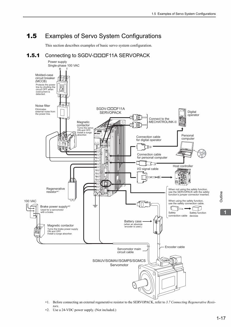
1.5 Examples of Servo System Configurations
1-17
1O
utli
ne
1.5 Examples of Servo System ConfigurationsThis section describes examples of basic servo system configuration.
1.5.1 Connecting to SGDV-F11A SERVOPACK
∗1. Before connecting an external regenerative resistor to the SERVOPACK, refer to 3.7 Connecting Regenerative Resis-tors.
∗2. Use a 24-VDC power supply. (Not included.)
SGDV-F11ASERVOPACK
SGMJV/SGMAV/SGMPS/SGMCS Servomotor
Power supply Single-phase 100 VAC
R T
100 VAC
Noise filter
Molded-casecircuit breaker (MCCB)Protects the power line by shutting thecircuit OFF whenovercurrent is detected.
Eliminatesexternal noise fromthe power line.
Magnetic contactor Turns the servo ON and OFF. Install a surge absorber.
Brake power supply∗2
Magnetic contactor
Regenerativeresistor∗1
Used for a servomotor with a brake.
Turns the brake power supply ON and OFF. Install a surge absorber.
Servomotor maincircuit cable
Encoder cable
Battery case (when an absolute encoder is used.)
I/O signal cable
Connection cable for digital operator
Connection cable for personal computer
Digital operator
Personal computer
Connect to the MECHATROLINK-II
Safety functiondevices
Host controller
When not using the safety function, use the SERVOPACK with the safety function’s jumper connector inserted.
When using the safety function, use the safety connection cable.
Safety connection cable
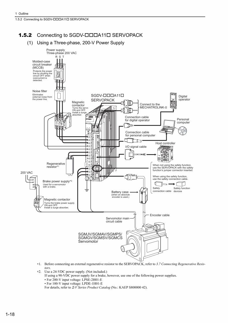
1 Outline
1.5.2 Connecting to SGDV-A11 SERVOPACK
1-18
1.5.2 Connecting to SGDV-A11 SERVOPACK
(1) Using a Three-phase, 200-V Power Supply
∗1. Before connecting an external regenerative resistor to the SERVOPACK, refer to 3.7 Connecting Regenerative Resis-tors.
∗2. Use a 24-VDC power supply. (Not included.) If using a 90-VDC power supply for a brake, however, use one of the following power supplies.• For 200-V input voltage: LPSE-2H01-E• For 100-V input voltage: LPDE-1H01-EFor details, refer to Σ-V Series Product Catalog (No.: KAEP S800000 42).
Brake power supply∗2
Servomotor maincircuit cable
Encoder cable
Battery case
Magnetic contactor
Regenerativeresistor∗1
Noise filter
Molded-case circuit breaker (MCCB)
Magnetic contactor
I/O signal cable
SGDV-A11SERVOPACK
SGMJV/SGMAV/SGMPS/ SGMGV/SGMSV/SGMCS Servomotor
Power supply Three-phase 200 VAC
R S T
Protects the power line by shutting thecircuit OFF whenovercurrent is detected.
Eliminatesexternal noise fromthe power line.
Used for a servomotor with a brake.
Turns the servo ON and OFF. Install a surge absorber.
Turns the brake power supply ON and OFF. Install a surge absorber.
(when an absolute encoder is used.)
Connection cable for digital operator
Connection cable for personal computer
Digitaloperator
Personal computer
200 VAC
Connect to the MECHATROLINK-II
Safety functiondevices
Host controller
When not using the safety function, use the SERVOPACK with the safety function’s jumper connector inserted.
When using the safety function, use the safety connection cable.
Safety connection cable

1.5 Examples of Servo System Configurations
1-19
1O
utli
ne
(2) Using a Single-phase, 200-V Power Supply
The Σ-V Series 200 V SERVOPACK generally specifies a three-phase power input but some models can be used with a single-phase 200 V power supply. Refer to 3.1.3 Using the SERVOPACK with Single-phase, 200 V Power Input for details.
∗1. Before connecting an external regenerative resistor to the SERVOPACK, refer to 3.7 Connecting Regenerative Resis-tors.
∗2. Use a 24-VDC power supply. (Not included.)
Brake power supply∗2
Servomotor maincircuit cable
Encoder cable
Battery case
Magnetic contactor
Regenerativeresistor∗1
Noise filter
Molded-case circuit breaker (MCCB)
Magnetic contactor
I/O signal cable
SGDV-A11 SERVOPACK
SGMJV/SGMAV/SGMPS/SGMCS Servomotor
Power supply Single-phase 200 VAC
R T
Protects the powerline by shutting thecircuit OFF whenovercurrent is detected.
Eliminatesexternal noise fromthe power line.
Used for a servomotor with a brake.
Turns the servo ON and OFF. Install a surge absorber.
Turns the brake power supply ON and OFF. Install a surge absorber.
(when an absolute encoder is used.)
Connection cable for digital operator
Connection cable for personal computer
Digitaloperator
Personal computer
200 VAC
Connect to the MECHATROLINK-II
Safety functiondevices
Host controller
When not using the safety function, use the SERVOPACK with the safety function’s jumper connector inserted.
When using the safety function, use the safety connection cable.
Safety connection cable

1 Outline
1.5.3 Connecting to SGDV-D11A SERVOPACK
1-20
1.5.3 Connecting to SGDV-D11A SERVOPACK
∗1. Use a 24-VDC power supply with double insulation or reinforced insulation. (The 24-VDC power supply is not included.) Do not use the same 24-VDC power supply for the brakes.
∗2. Before connecting an external regenerative resistor to the SERVOPACK, refer to 3.7 Connecting Regenerative Resis-tors.
∗3. Use a 24-VDC power supply for a brake. (Not included.)If using a 90-VDC power supply for a brake, however, use one of the following power supplies.• For 200-V input voltage: LPSE-2H01-E• For 100-V input voltage: LPDE-1H01-EFor details, refer to Σ-V Series Product Catalog (No.: KAEP S800000 42).
Brake power supply*3
Battery case
Magnetic contactor
Noise filter
Molded-case circuit breaker (MCCB)
Magnetic contactor
I/O signal cable
Power supply Three-phase 400 VAC
Protects the power line by shuttingthe circuit OFF whenovercurrent is detected.
Eliminatesexternal noise fromthe power line.
Used for a servomotorwith a brake.
Turns the servo ON and OFF. Install a surge absorber.
Turns the brake power supply ON and OFF. Install a surge absorber.
(when an absolute encoder is used.)
Connection cable for digital operator
Connection cable for personal computer
Digitaloperator
Personal computer
Regenerativeresistor∗2
Servomotor maincircuit cable
Encoder cable
SGMSV/SGMGV Servomotor
SGDV-D11A SERVOPACK
R S T
DC powersupply (24 V)∗1
100/200 VAC
Connect to the MECHATROLINK-II
Safety functiondevices
Host controller
When not using the safety function, use the SERVOPACK with the safety function’s jumper connector inserted.
When using the safety function, use the safety connection cable.
Safety connection cable

1.6 SERVOPACK Model Designation
1-21
1O
utli
ne
1.6 SERVOPACK Model DesignationThis section shows SERVOPACK model designation.
∗1. These amplifiers can be powered with single or three-phase.∗2. SGDV-120A1A008000, a special version of the 1.5 kW amplifier can be used for single-phase operation.∗3. SGDV-470A, -550A, -590A, -780A, -210D, -260D, -280D, and -370D are duct-ventilated types.∗4. A resistor for the dynamic brake is not included. An external resistor for the dynamic brake can only be used with
400-V SERVOPACKs.Note: If the option codes digits 8 to 13 are all zeros, they are omitted.
SGDV
Series
SGDV Σ-V Series
1st + 2nd + 3rd digits: Current
Voltage CodeMax. Allowable Motor Capacity
(kW)
100 V
R70 0.05
R90 0.1
2R1 0.2
2R8 0.4
200 V
R70*1 0.05
R90*1 0.1
1R6*1 0.2
2R8*1 0.4
3R8 0.5
5R5*1 0.75
7R6 1
120*2 1.5
180 2
200 3
330 5
470*3 6
550*3 7.5
590*3 11
780*3 15
400 V
1R9 0.5
3R5 1
5R4 1.5
8R4 2
120 3
170 5
210*3 6
260*3 7.5
280*3 11
370*3 15
4th digit: Voltage
Code Voltage
F 100 V
A 200 V
D 400 V
5th + 6th digits: Interface Specifications
Code Interface
01 Analog voltage and pulse train reference, rotational servomotor
05 Analog voltage and pulse train reference, linear servomotor
11 MECHATROLINK-II communications ref-erence, rotational servomotor
15 MECHATROLINK-II communications ref-erence, linear servomotor
21 MECHATROLINK-III communications reference, rotational servomotor
25 MECHATROLINK-III communications reference, linear servomotor
11th + 12th digits: Software Specification
Code Specification
00 Standard
–
7th digit: Design Revision Order
1st + 2nd + 3rd digits
4thdigit
5th + 6th digits
7thdigit
2R8 A 11 A
8th + 9th + 10th digits
000
8th + 9th + 10th digits: Hardware Specifications
Code Specifications
000 Base-mounted (standard)
001 Rack-mounted*3
002 Varnished
003 Rack-mounted*3 and Varnished
008 Single-phase, 200-V Power Supply (SGDV-120A1A008000)
020 Dynamic brake (DB)*4
11th + 12thdigits
00
13thdigit
0
13th digit: Parameter Specification
Code Specification
0 Standard

1 Outline
1.7.1 SERVOPACK Inspection
1-22
1.7 Servo Drive Maintenance and InspectionThis section describes the inspection and maintenance of a servo drive.
1.7.1 SERVOPACK InspectionFor inspection and maintenance of the SERVOPACK, follow the inspection procedures in the following table at least once every year. Other routine inspections are not required.
1.7.2 SERVOPACK’s Parts Replacement ScheduleThe following electric or electronic parts are subject to mechanical wear or deterioration over time. To avoid failure, replace these parts at the frequency indicated.
Refer to the standard replacement period in the following table and contact your Yaskawa representative. After an examination of the part in question, we will determine whether the parts should be replaced or not.
Note: The standard replacement period is given for usage under the following operating conditions.• Surrounding air temperature: Annual average of 30°C• Load factor: 80% max.• Operation rate: 20 hours/day max.
Item Frequency Procedure Comments
Exterior
At least once a year
Check for dust, dirt, and oil on the surfaces.
Clean with a cloth or com-pressed air.
Loose ScrewsCheck for loose terminal block and connector screws.
Tighten any loose screws.
The parameters of any SERVOPACKs overhauled by Yaskawa are reset to the factory settings before shipping. Be sure to confirm that the parameters are properly set before starting operation.
Part Standard Replacement Period
Cooling Fan 4 to 5 years
Smoothing Capacitor 7 to 8 years
Other Aluminum Electrolytic Capacitor 5 years
Relays –
Fuses 10 years

1.7 Servo Drive Maintenance and Inspection
1-23
1O
utli
ne
1.7.3 Servomotor InspectionThe AC servomotor is brushless and simple daily inspection is sufficient. Use the inspection frequencies given in the following table as a guide. Determine the most appropriate inspection frequency from the actual usage conditions and the environment.
∗ Measure the insulation resistance between the U, V, or W phase on the servomotor’s power line and the frame ground.
Inspected Item Inspection Frequency or Interval
Inspection or Maintenance Procedure Remark
Vibration and Noise Check Daily
Inspect by touching and listening to the servomotor.
There should be no more vibration or noise than normal.
Appearance Inspection
Depends on amount of dirt.
Clean with a cloth or compressed air. −
Insulation Resistance Mea-surement
At least once a year
Disconnect the servomotor from the SERVOPACK and measure the insulation resistance with a 500 V insulation resistance meter.* The servomotor is normal if the resistance is higher than 10 MΩ.
• If the resistance is 10 MΩ or lower, contact your Yaskawa rep-resentative.
• Do not measure the insulation resistance of the encoder or per-form a withstand test on it.
Oil Seal Replacement
At least once every 5,000 hours
Contact your Yaskawa represen-tative.
Only necessary if the servomotor has an oil seal.
Overhaul At least once every 5 years or 20,000 hours
Contact your Yaskawa represen-tative. −

2-1
2P
ane
l Dis
pla
y an
d O
pera
tion
of D
igita
l Ope
rato
r
2Panel Display and
Operation of Digital Operator
2.1 Panel Display . . . . . . . . . . . . . . . . . . . . . . . . . . . . . . . . . . . . . . . . . . . . . .2-22.1.1 Status Display . . . . . . . . . . . . . . . . . . . . . . . . . . . . . . . . . . . . . . . . . . . . . . . . . . . . . . . 2-22.1.2 Alarm and Warning Display . . . . . . . . . . . . . . . . . . . . . . . . . . . . . . . . . . . . . . . . . . . . . 2-22.1.3 Hard Wire Base Block Display . . . . . . . . . . . . . . . . . . . . . . . . . . . . . . . . . . . . . . . . . . 2-22.1.4 Overtravel Display . . . . . . . . . . . . . . . . . . . . . . . . . . . . . . . . . . . . . . . . . . . . . . . . . . . . 2-2
2.2 Operation of Digital Operator . . . . . . . . . . . . . . . . . . . . . . . . . . . . . . . . . .2-3
2.3 Utility Functions (Fn) . . . . . . . . . . . . . . . . . . . . . . . . . . . . . . . . . . . .2-3
2.4 Parameters (Pn) . . . . . . . . . . . . . . . . . . . . . . . . . . . . . . . . . . . . . . .2-42.4.1 Parameter Classification . . . . . . . . . . . . . . . . . . . . . . . . . . . . . . . . . . . . . . . . . . . . . . . 2-42.4.2 Notation for Parameters . . . . . . . . . . . . . . . . . . . . . . . . . . . . . . . . . . . . . . . . . . . . . . . 2-42.4.3 Setting Parameters . . . . . . . . . . . . . . . . . . . . . . . . . . . . . . . . . . . . . . . . . . . . . . . . . . . 2-5
2.5 Monitor Displays (Un) . . . . . . . . . . . . . . . . . . . . . . . . . . . . . . . . . . .2-7

2 Panel Display and Operation of Digital Operator
2.1.1 Status Display
2-2
2.1 Panel DisplayYou can use the panel display on the SERVOPACK to check the status of the servo drive.Also, if an alarm or warning occurs, its alarm or warning number is displayed.
2.1.1 Status DisplayThe display shows the following status.
2.1.2 Alarm and Warning DisplayIf an alarm or warning occurs, the display will change in the following order.
Example: Alarm A.E60
2.1.3 Hard Wire Base Block DisplayIf a hard wire base block (HWBB) occurs, the display will change in the following order.
2.1.4 Overtravel DisplayIf overtraveling occurs, the display will change in the following order.
Display Meaning
Rotation Detection (/TGON)Lights if motor speed exceeds the value set in Pn502. (Factory setting: 20 min-1)
BaseblockLights for baseblock (Servomotor power OFF).
Reference Input Lights when a reference is being input.
CONNECT Lights during connection.
Status
Display
Unlit Unlit Unlit Unlit Unlit
StatusDisplay
Unlit Unlit Unlit Unlit
Overtravel at forward rotation (P-OT)
Currentstatus
Currentstatus
Currentstatus
1
Overtravel at reverse rotation (N-OT)2
Overtravel at forward/reverse rotation3

2.2 Operation of Digital Operator
2-3
2P
ane
l Dis
pla
y an
d O
pera
tion
of D
igita
l Ope
rato
r
2.2 Operation of Digital OperatorOperation examples of utility functions (Fn), parameters (Pn) and monitor displays (Un) when using a digital operator are described in this chapter.
Operations can be also performed with SigmaWin+.
For more information on the usage of the digital operator, refer to Σ-V Series USER’S MANUAL Operation of Digital Operator (No.: SIEP S800000 55).
2.3 Utility Functions (Fn)
The utility functions are related to the setup and adjustment of the SERVOPACK.
The digital operator shows numbers beginning with Fn.The following table outlines the procedures necessary for an origin search (Fn003).
Step Display after Operation Keys Operation
1
Press the Key to view the main menu for the util-ity function.
Use the or Key to move through the list and select Fn003.
2 Press the Key. The display changes to the Fn003 execution display.
3
Press the Key.The status display changes from "BB" to "RUN", and the servomotor power turns ON.Note: If the servomotor is already at the zero position,
"-Complete-" is displayed.
4
Pressing the Key will rotate the servomotor in the
forward direction. Pressing the Key will rotate the servomotor in the reverse direction. The rotation direc-tion of the servomotor changes according to the setting of Pn000.0 as shown in the following table.
Note: Direction when viewed from the load of the ser-vomotor.
Press the or Key until the servomotor stops. If the origin search completed normally, "-Complete-" is displayed on the right top on the screen.
5
When the origin search is completed, press the Key.The status display changes from "RUN" to "BB", and the servomotor turns OFF. The display "-Complete-" changes to "-Z-Search-."
6Press the Key.The display returns to the main menu of the utility function.
7 To enable the change in the setting, turn the power OFF and ON again.
B B − F U N C T I O N −F n 0 0 2 : J O GF n 0 0 3 : Z − S e a r c hF n 0 0 4 : P r o g r a m J O GF n 0 0 5 : P r m I n i t
B B − Z − S e a r c h −U n 0 0 0 = 0 0 0 0 0 0U n 0 0 2 = 0 0 0 0 0 0U n 0 0 3 = 0 0 0 0 0 0 0 0 7 7 4U n 0 0 D = 0 0 0 0 0 0 0 0 0 0 0
R U N − Z − S e a r c h −U n 0 0 0 = 0 0 0 0 0 0U n 0 0 2 = 0 0 0 0 0 0U n 0 0 3 = 0 0 0 0 0 0 0 0 7 7 4U n 0 0 D = 0 0 0 0 0 0 0 0 0 0 0
R U N − C o m p l e t e −U n 0 0 0 = 0 0 0 0 0 0U n 0 0 2 = 0 0 0 0 0 0U n 0 0 3 = 0 0 0 0 0 0 0 0 0 0 0U n 0 0 D = 0 0 0 0 0 0 0 1 D 5 8
Parameter key key
Pn000n.0 CCW CW
n.1 CW CCW
B B − Z − S e a r c h −U n 0 0 0 = 0 0 0 0 0 0U n 0 0 2 = 0 0 0 0 0 0U n 0 0 3 = 0 0 0 0 0 0 0 0 0 0 0U n 0 0 D = 0 0 0 0 0 0 0 1 D 5 8
B B − F U N C T I O N −F n 0 0 2 : J O GF n 0 0 3 : Z − S e a r c hF n 0 0 4 : P r o g r a m J O GF n 0 0 5 : P r m I n i t

2 Panel Display and Operation of Digital Operator
2.4.1 Parameter Classification
2-4
2.4 Parameters (Pn)This section describes the classifications, methods of notation, and settings for parameters given in this man-ual.
2.4.1 Parameter ClassificationParameters of the Σ-V Series SERVOPACK are classified into two types of parameters. One type of parame-ters is required for setting up the basic conditions for operation and the other type is required for tuning param-eters that are required to adjust servomotor characteristics.
There are two types of notation used for parameters, one for parameter that requires a value setting (parameter for numeric settings) and one for parameter that requires the selection of a function (parameter for selecting functions).
The notation and settings for both types of parameters are described next.
2.4.2 Notation for Parameters
(1) Parameters for Numeric Settings
Classification Meaning Display Method Setting Method
Setup Parameters Parameters required for setup.
Always displayed (Factory setting: Pn00B.0 = 0)
Set each parameter individu-ally.
Tuning ParametersParameters for tuning con-trol gain and other parame-ters.
Set Pn00B.0 to 1. There is no need to set each parameter individually.
Pn406 Emergency Stop Torque
Setting Range
0 to 800 1% 800 After change
Setting Unit Factory Setting When Enabled Classification
Setup
Parameter number
Position Torque The control methods for which the parameters applies.Speed : Speed control : Position control : Torque control
Indicates the parameter setting before shipment.
Indicates when a change to the parameter will be effective.
Indicates the parameter classification.
Indicates the minimum setting unit for the parameter.
Torque Position Speed
Indicates the setting range for the parameter.
Parameter Meaning When Enabled Classification
Pn002 After restart
n.0 [Factory setting]
n.1 Uses the absolute encoder as an incremental encoder.
Uses the absolute encoder as an absolute encoder.
Setup
Parameter number
The notation “n.” indicates a parameter for selecting functions. Each corresponds to the setting value of that digit. The notation shown here means that the third digit is 1.
This section explains the selections for the function.
(2) Parameters for Selecting Functions

2.4 Parameters (Pn)
2-5
2P
ane
l Dis
pla
y an
d O
pera
tion
of D
igita
l Ope
rato
r
• Notation Example
2.4.3 Setting Parameters
(1) How to Make Numeric Settings Using Parameters
The following example shows how to change the setting of parameter Pn304 (JOG speed) to 1000 min-1.
1st digit
2nd digit
3rd digit
4th digit
Digital Operator Display (Display Example for Pn002) Digit Notation Setting Notation
Meaning Notation Meaning
Pn002.0
Pn002.1
Pn002.2
Pn002.3
Indicates the value for the 1st digit of parameter Pn002. Indicates the value for the 2nd digit of parameter Pn002. Indicates the value for the 3rd digit of parameter Pn002. Indicates the value for the 4th digit of parameter Pn002.
Pn002.0 = x or n.x Pn002.1 = x or n.x
Indicates that the value for the 1st digit of parameter Pn002 is x. Indicates that the value for the 2nd digit of parameter Pn002 is x.
Pn002.2 = x or n.x Pn002.3 = x or n.x
Indicates that the value for the 3rd digit of parameter Pn002 is x. Indicates that the value for the 4th digit of parameter Pn002 is x.
Notation
Step Display after Operation Keys Operation
1 Press the Key to select the main menu of parame-ters and monitor displays.
2 Press the or Key to move the cursor to "Un."
3 Press the or Key to change "Un" to "Pn."
4 Press the Key to move the cursor to the column on the right of "Pn."
5
Press the arrow keys to display "Pn304".
To move the cursor to different columns: , Key
To change the settings: , Key
6 Press the Key to move the cursor to the one’s place of Pn304.
7 Press the Key twice to move the cursor to the hun-dred’s place of Pn304.
8 Press the Key five times to change the setting to "1000."

2 Panel Display and Operation of Digital Operator
2.4.3 Setting Parameters
2-6
(2) How to Select Functions Using Parameters
The following example shows how to set the function section for insufficient voltage of the application func-tion select switch 8 (Pn008) to 1 "detects warning and limits torque by host controller."
9 Press the Key to write the settings.
(cont’d)
Step Display after Operation Keys Operation
Step Display after Operation Keys Operation
1 Press the Key to select the main menu of param-eters and monitor displays.
2 Press the or Key to move the cursor to "Un."
3 Press the or Key to change "Un" to "Pn."
4 Press the Key three times to move the cursor to the column on the right of "Pn."
5 Press the Key to display "Pn008."
6 Press the Key to move the cursor to "Pn008.0."
7 Press the Key once to move the cursor to "Pn008.1."
8 Press the Key to change the setting of "Pn008.1" to "1."
9 Press the Key to write the settings.

2.5 Monitor Displays (Un)
2-7
2P
ane
l Dis
pla
y an
d O
pera
tion
of D
igita
l Ope
rato
r
2.5 Monitor Displays (Un)The monitor displays can be used for monitoring the reference values, I/O signal status, and SERVOPACK internal status.
For details, refer to 7.2 Viewing Monitor Displays.
The digital operator shows numbers beginning with Un.
The following four settings are the factory settings.
Shows the setting of Un000 (motor rotating speed) as 0 min-1.

3-1
3
Wiri
ng
and
Con
nect
ion
3Wiring and Connection
3.1 Main Circuit Wiring . . . . . . . . . . . . . . . . . . . . . . . . . . . . . . . . . . . . . . . . . .3-23.1.1 Main Circuit Terminals . . . . . . . . . . . . . . . . . . . . . . . . . . . . . . . . . . . . . . . . . . . . . . . . . 3-23.1.2 Using a Standard Power Supply (Sin-
gle-phase 100 V, Three-phase 200 V, or Three-phase 400 V) . . . . . . . . . . . . . . . . . . 3-33.1.3 Using the SERVOPACK with Single-phase, 200 V Power Input . . . . . . . . . . . . . . . . 3-113.1.4 Using the SERVOPACK with a DC Power Input . . . . . . . . . . . . . . . . . . . . . . . . . . . . 3-143.1.5 Using More Than One SERVOPACK . . . . . . . . . . . . . . . . . . . . . . . . . . . . . . . . . . . . 3-163.1.6 General Precautions for Wiring . . . . . . . . . . . . . . . . . . . . . . . . . . . . . . . . . . . . . . . . . 3-17
3.2 I/O Signal Connections . . . . . . . . . . . . . . . . . . . . . . . . . . . . . . . . . . . . . .3-183.2.1 I/O Signal (CN1) Names and Functions . . . . . . . . . . . . . . . . . . . . . . . . . . . . . . . . . . 3-183.2.2 Safety Function Signal (CN8) Names and Functions . . . . . . . . . . . . . . . . . . . . . . . . 3-193.2.3 Example of I/O Signal Connections . . . . . . . . . . . . . . . . . . . . . . . . . . . . . . . . . . . . . 3-20
3.3 I/O Signal Allocations . . . . . . . . . . . . . . . . . . . . . . . . . . . . . . . . . . . . . . . 3-213.3.1 Input Signal Allocations . . . . . . . . . . . . . . . . . . . . . . . . . . . . . . . . . . . . . . . . . . . . . . . 3-213.3.2 Output Signal Allocations . . . . . . . . . . . . . . . . . . . . . . . . . . . . . . . . . . . . . . . . . . . . . 3-23
3.4 Examples of Connection to Host Controller . . . . . . . . . . . . . . . . . . . . . .3-243.4.1 Sequence Input Circuit . . . . . . . . . . . . . . . . . . . . . . . . . . . . . . . . . . . . . . . . . . . . . . . 3-243.4.2 Sequence Output Circuit . . . . . . . . . . . . . . . . . . . . . . . . . . . . . . . . . . . . . . . . . . . . . . 3-25
3.5 Wiring MECHATROLINK-II Communications . . . . . . . . . . . . . . . . . . . . . 3-27
3.6 Encoder Connection . . . . . . . . . . . . . . . . . . . . . . . . . . . . . . . . . . . . . . . . 3-283.6.1 Encoder Signal (CN2) Names and Functions . . . . . . . . . . . . . . . . . . . . . . . . . . . . . . 3-283.6.2 Encoder Connection Examples . . . . . . . . . . . . . . . . . . . . . . . . . . . . . . . . . . . . . . . . . 3-28
3.7 Connecting Regenerative Resistors . . . . . . . . . . . . . . . . . . . . . . . . . . . .3-303.7.1 Connecting Regenerative Resistors . . . . . . . . . . . . . . . . . . . . . . . . . . . . . . . . . . . . . 3-303.7.2 Setting Regenerative Resistor Capacity . . . . . . . . . . . . . . . . . . . . . . . . . . . . . . . . . . 3-32
3.8 Noise Control and Measures for Harmonic Suppression . . . . . . . . . . . .3-333.8.1 Wiring for Noise Control . . . . . . . . . . . . . . . . . . . . . . . . . . . . . . . . . . . . . . . . . . . . . . 3-333.8.2 Precautions on Connecting Noise Filter . . . . . . . . . . . . . . . . . . . . . . . . . . . . . . . . . . 3-353.8.3 Connecting a Reactor for Harmonic Suppression . . . . . . . . . . . . . . . . . . . . . . . . . . . 3-36

3 Wiring and Connection
3.1.1 Main Circuit Terminals
3-2
3.1 Main Circuit WiringThe names and specifications of the main circuit terminals are given below.
Also this section describes the general precautions for wiring and precautions under special environments.
3.1.1 Main Circuit Terminals
: Main circuit terminals
Terminal Symbols Name Model SGDV- Specification
L1, L2Main circuit power in-put terminals
F Single-phase 100 to 115 V, +10 to -15%, 50/60 Hz
L1, L2, L3A Three-phase 200 to 230 V, +10 to -15%, 50/60 Hz
D Three-phase 380 to 480 V, +10 to -15%, 50/60 Hz
L1C, L2C Control power input terminals
F Single-phase 100 to 115 V, +10 to -15%, 50/60 Hz
A Single-phase 200 to 230 V, +10 to -15%, 50/60 Hz
24V, 0V D 24 VDC, ±15%
B1/ , B2*1External regenera-tive resistor connec-tion terminals
R70F, R90F, 2R1F, 2R8F, R70A, R90A, 1R6A, 2R8A
If the regenerative capacity is insufficient, connect an external regenerative resistor between B1/ and B2. Note: The external regenerative resistor is not
included.
3R8A, 5R5A, 7R6A, 120A, 180A, 200A, 330A, 1R9D, 3R5D, 5R4D, 8R4D, 120D, 170D
If the internal regenerative resistor is insufficient, remove the lead or shorting bar between B2 and B3 and connect an external regenerative resistor between B1/ and B2. Note: The external regenerative resistor is not
included.
470A, 550A, 590A, 780A, 210D, 260D, 280D, 370D
Connect a regenerative resistor unit between B1/ and B2. Note: The regenerative resistor unit is not included.
1, 2*2
DC reactor connec-tion terminal for pow-er supply harmonic suppression
AD
If a countermeasure against power supply harmonic waves is needed, connect a DC reactor between 1 and 2.

3.1 Main Circuit Wiring
3-3
3
Wiri
ng
and
Con
nect
ion
∗1. Do not short-circuit between B1/ and B2. It may damage the SERVOPACK.∗2. The DC reactor connection terminals are short-circuited when the SERVOPACK is shipped from the factory: 1 and
2.
3.1.2 Using a Standard Power Supply (Single-phase 100 V, Three-phase 200 V, or Three-phase 400 V)
(1) Wire Types
Use the following type of wire for main circuit.
The following table shows the wire sizes and allowable currents for three wires. Use wires with specifications equal to or less than those shown in the table.
Note: The values in the table are for reference only.
B1/Main circuit positive terminal
AD
Use when DC power supply input is used.2 or Main circuit negative
terminalAD
U, V, WServomotor connec-tion terminals Use for connecting to the servomotor.
Ground terminals(× 2)
Use for connecting the power supply ground terminal and servomotor ground terminal.
(cont’d)
Terminal Symbols
Name Model SGDV- Specification
Cable TypeAllowable Conductor Temperature °C
Symbol Name
IV 600 V grade polyvinyl chloride insulated wire 60
HIV 600 V grade heat-resistant polyvinyl chloride insulated wire 75
AWG Size
Nominal Cross
Section Area (mm2)
Configuration(Number of Wires/mm)
Conductive Resistance
(Ω/km)
Allowable Current at Surrounding Air Temperature (A)
30°C 40°C 50°C
20 0.5 19/0.18 39.5 6.6 5.6 4.5
19 0.75 30/0.18 26.0 8.8 7.0 5.5
18 0.9 37/0.18 24.4 9.0 7.7 6.0
16 1.25 50/0.18 15.6 12.0 11.0 8.5
14 2.0 7/0.6 9.53 23 20 16
12 3.5 7/0.8 5.41 33 29 24
10 5.5 7/1.0 3.47 43 38 31
8 8.0 7/1.2 2.41 55 49 40
6 14.0 7/1.6 1.35 79 70 57
4 22.0 7/2.0 0.85 91 81 66

3 Wiring and Connection
3.1.2 Using a Standard Power Supply (Single-phase 100 V, Three-phase 200 V, or Three-phase 400 V)
3-4
(2) Main Circuit Wires
This section describes the main circuit wires for SERVOPACKs.
Single-phase, 100 V
Three-phase, 200 V
Three-phase, 400 V
• The specified wire sizes are for use when the three lead cables are bundled and when the rated electric current is applied with a surrounding air temperature of 40°C.
• Use a wire with a minimum withstand voltage of 600 V for the main circuit.
• If cables are bundled in PVC or metal ducts, take into account the reduction of the allowable current.
• Use a heat-resistant wire under high surrounding air or panel temperatures, where polyvinyl chloride insulated wires will rapidly deteriorate.
Terminal Symbols
NameSGDV-F
R70 R90 2R1 2R8
L1, L2Main circuit power input termi-nals HIV1.25 HIV2.0
L1C, L2C Control power input terminals HIV1.25
U, V, W Servomotor connection termi-nals
HIV1.25
B1/ , B2External regenerative resistor connection terminals HIV1.25
Ground terminal HIV2.0 or larger
Terminal Symbols Name
SGDV-A (Unit: mm2)
R70 R90 1R6 2R8 3R8 5R5 7R6 120 180 200 330 470 550 590 780
L1, L2, L3
Main circuit power in-put terminals HIV1.25 HIV2.0 HIV3.5 HIV
5.5HIV8.0
HIV14.0 HIV22.0
L1C, L2CControl power input terminals HIV1.25
U, V, W Servomotor connec-tion terminals
HIV1.25 HIV2.0 HIV3.5
HIV5.5
HIV8.0
HIV14.0 HIV22.0
B1/ , B2
External regenerative resistor connection terminals
HIV1.25 HIV2.0
HIV3.5
HIV5.5
HIV8.0 HIV22.0
Ground terminal HIV2.0 or larger
Terminal Symbols Name
SGDV-D (Unit: mm2)
1R9 3R5 5R4 8R4 120 170 210 260 280 370
L1, L2, L3 Main circuit power input termi-nals HIV1.25 HIV2.0 HIV3.5 HIV
5.5HIV8.0
HIV14.0
24V, 0V Control power input terminals HIV1.25
U, V, W Servomotor connection termi-nals HIV1.25 HIV2.0 HIV
3.5 HIV5.5 HIV8.0
HIV14.0
B1/ , B2External regenerative resistor connection terminals HIV1.25
HIV2.0 HIV3.5
HIV5.5
HIV8.0
Ground terminal HIV2.0 or larger

3.1 Main Circuit Wiring
3-5
3
Wiri
ng
and
Con
nect
ion
(3) Typical Main Circuit Wiring Examples
Note the following points when designing the power ON sequence.
• Design the power ON sequence so that main power is turned OFF when a servo alarm signal (ALM) is output.
• The ALM signal is output for a maximum of five seconds when the control power is turned ON. Take this into consid-eration when designing the power ON sequence. Design the sequence so the ALM signal is activated and the alarm detection relay (1Ry) is turned OFF to stop the main circuit’s power supply to the SERVOPACK.
• Select the power supply specifications for the parts in accordance with the input power supply.
The typical main circuit wiring examples are shown below.
Single-phase 100 V, SGDV-F (SGDV-R70F, -R90F, -2R1F, -2R8F)
• When turning ON the control power supply and the main circuit power supply, turn them ON at the same time or turn the main circuit power supply after the control power supply. When turning OFF the power supplies, first turn the power for the main circuit OFF and then turn OFF the control power supply.
WARNING• Do not touch the power supply terminals after turning OFF the power. High voltage may still remain in the
SERVOPACK, resulting in electric shock. When the voltage is discharged, the charge indicator will turn OFF. Make sure the charge indicator is OFF before starting wiring or inspections.
Control power supply
ALM signal
5.0 s max.
L1
ENC
U V W
M
0 V
1Ry +
−
3
4 1D
2KM
1KM
B2
L2
CN1
1QF
R T
+24 V B1/
3SA
1Ry
1PL
1KM
2KM 1SA 1KM
1Ry 1KM
2SA
L1C L2C
ALM
ALM
1FLT
1PL: Indicator lamp1SA: Surge absorber2SA: Surge absorber3SA: Surge absorber1D: Flywheel diode
1QF: Molded-case circuit breaker1FLT: Noise filter1KM: Magnetic contactor (for control power supply)2KM: Magnetic contactor (for main circuit power supply)1Ry: Relay
SERVOPACK SGDV-F
(For servo alarm display)
supply ON Servo power
supply OFF Servo power
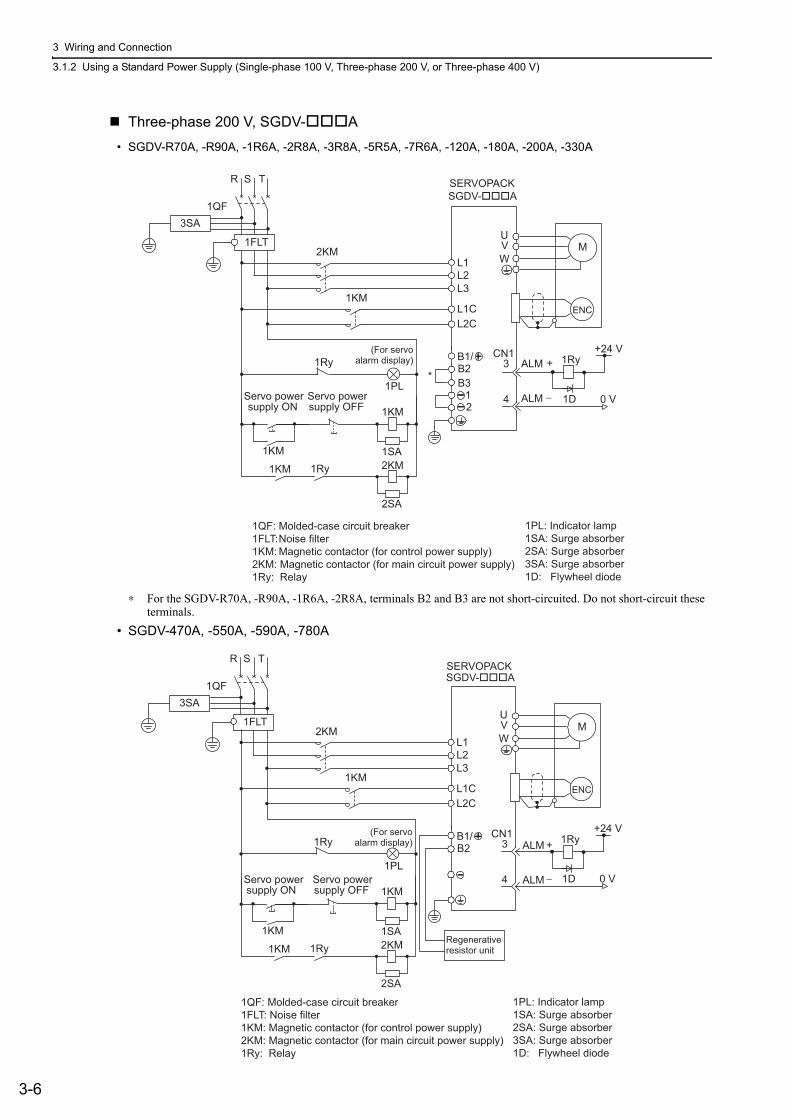
3 Wiring and Connection
3.1.2 Using a Standard Power Supply (Single-phase 100 V, Three-phase 200 V, or Three-phase 400 V)
3-6
Three-phase 200 V, SGDV-A
• SGDV-R70A, -R90A, -1R6A, -2R8A, -3R8A, -5R5A, -7R6A, -120A, -180A, -200A, -330A
∗ For the SGDV-R70A, -R90A, -1R6A, -2R8A, terminals B2 and B3 are not short-circuited. Do not short-circuit these terminals.
• SGDV-470A, -550A, -590A, -780A
2KM L1
ENC
U V W
M
0 V
1Ry +
−
3
4 1D
B2 B3
L2
CN1
1KM L1C
L3
L2C
1QF
R S T
1FLT
+24 V
1 2
3SA
*
B1/
1PL
1KM
2KM 1SA
2SA
1KM 1Ry 1KM
ALM
ALM
1Ry
1PL: Indicator lamp1SA: Surge absorber2SA: Surge absorber3SA: Surge absorber1D: Flywheel diode
1QF: Molded-case circuit breaker1FLT: Noise filter1KM: Magnetic contactor (for control power supply)2KM: Magnetic contactor (for main circuit power supply)1Ry: Relay
SERVOPACK SGDV-A
(For servo alarm display)
supply ON Servo power
supply OFF Servo power
2KM L1
ENC
U V W
M
0 V
1Ry
1D
B2
L2
1KM L1C
L3
L2C
1QF
R S T
1FLT
+24 V
3SA
B1/
1PL
1KM
2KM 1SA
2SA
+
−
3
4
CN1
1KM 1Ry 1KM
ALM
ALM
1Ry
SGDV-A
Regenerative resistor unit
(For servo alarm display)
supply ON Servo power
supply OFF Servo power
SERVOPACK
1QF: Molded-case circuit breaker1FLT: Noise filter1KM: Magnetic contactor (for control power supply)2KM: Magnetic contactor (for main circuit power supply)1Ry: Relay
1PL: Indicator lamp1SA: Surge absorber2SA: Surge absorber3SA: Surge absorber1D: Flywheel diode
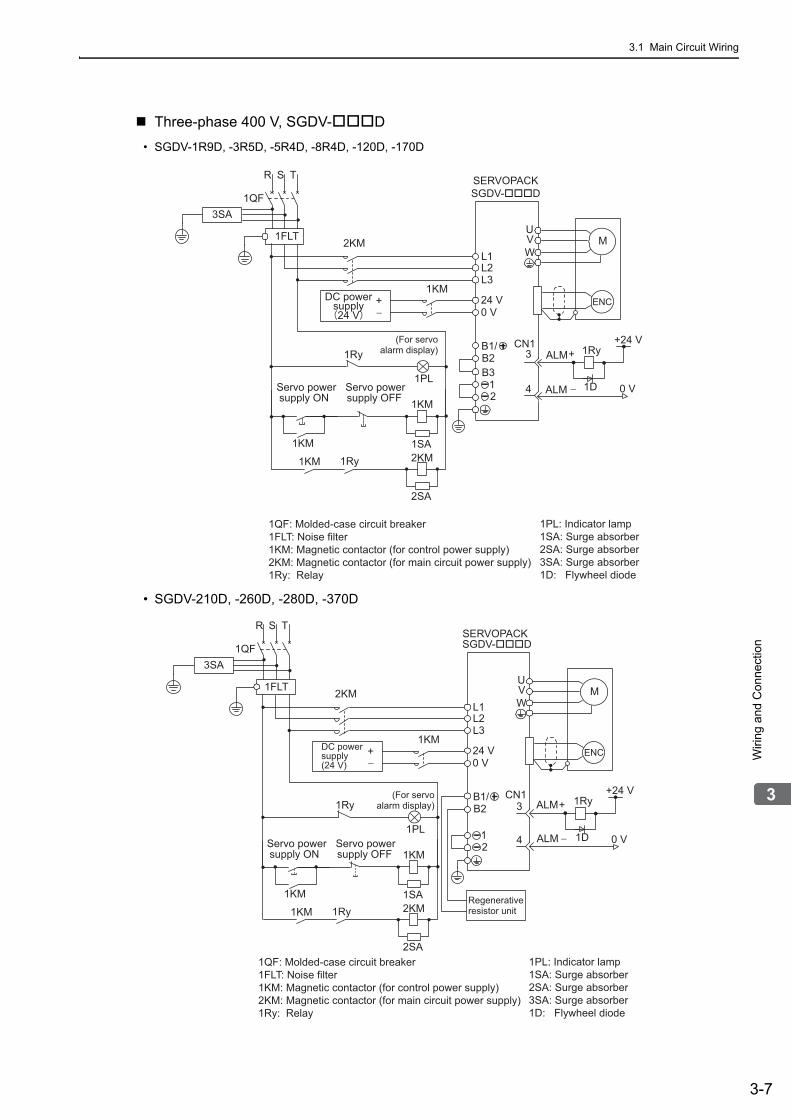
3.1 Main Circuit Wiring
3-7
3
Wiri
ng
and
Con
nect
ion
Three-phase 400 V, SGDV-D
• SGDV-1R9D, -3R5D, -5R4D, -8R4D, -120D, -170D
• SGDV-210D, -260D, -280D, -370D
ENC
U V W
M
0 V
1Ry
1D
1QF
R S T
1FLT
+24 V
3SA
B2 B3
1 2
B1/
1PL
1KM
2KM 1SA
2SA
L1 2KM
L2 L3
24 V+ −
1KM
0 V
+
−
3
4
CN1
1KM 1Ry 1KM
ALM
ALM
1Ry
1QF: Molded-case circuit breaker1FLT: Noise filter1KM: Magnetic contactor (for control power supply)2KM: Magnetic contactor (for main circuit power supply)1Ry: Relay
1PL: Indicator lamp1SA: Surge absorber2SA: Surge absorber3SA: Surge absorber1D: Flywheel diode
DC powersupply24 V
(For servo alarm display)
supply ON Servo power
supply OFF Servo power
SERVOPACKSGDV-D
ENC
U V W
M
0 V
1Ry
1D
1QF
R S T
1FLT
+24 V
3SA
B2
1 2
B1/
1PL
1KM
2KM 1SA
2SA
L1 2KM
L2 L3
24 V+ −
1KM
0 V
+
−
3
4
CN1
1KM 1Ry 1KM
ALM
ALM
1Ry
SGDV-D
DC power supply (24 V)
Regenerative resistor unit
(For servo alarm display)
supply ON Servo power
supply OFF Servo power
SERVOPACK
1QF: Molded-case circuit breaker1FLT: Noise filter1KM: Magnetic contactor (for control power supply)2KM: Magnetic contactor (for main circuit power supply)1Ry: Relay
1PL: Indicator lamp1SA: Surge absorber2SA: Surge absorber3SA: Surge absorber1D: Flywheel diode

3 Wiring and Connection
3.1.2 Using a Standard Power Supply (Single-phase 100 V, Three-phase 200 V, or Three-phase 400 V)
3-8
(4) Power Supply Capacities and Power Losses
The following table shows the SERVOPACK’s power supply capacities and power losses.
∗1. The value in parentheses is for the JUSP-RA04-E regenerative resistor unit. ∗2. The value in parentheses is for the JUSP-RA05-E regenerative resistor unit. ∗3. The value in parentheses is for the JUSP-RA18-E regenerative resistor unit. ∗4. The value in parentheses is for the JUSP-RA19-E regenerative resistor unit. Note 1. SGDV-R70F, -R90F, -2R1F, -2R8F, -R70A, -R90A, -1R6A, and -2R8A SERVOPACKs do not have built-in
regenerative resistors. Connect an external regenerative resistor if the regenerative energy exceeds the specified value.
2. SGDV-470A, -550A, -590A, -780A, -210D, -260D, -280D, and -370D SERVOPACKs do not have built-in regenerative resistors. Make sure that a regenerative resistor unit or an external regenerative resistor is connected. Refer to 3.7 Connecting Regenerative Resistors for details.
3. Regenerative resistor power losses are the allowable losses. Take the following actions if this value is exceeded.• Remove the lead or shorting bar between terminals B2 and B3 on the SERVOPACK main circuit for SGDV-
3R8A, -5R5A, -7R6A, -120A, -180A, -200A, -330A, and 400-V SERVOPACKs.• Install an external regenerative resistor. Refer to 3.7 Connecting Regenerative Resistors for details.
MainCircuit Power Supply
Maximum Applicable Servomotor
Capacity[kW]
SERVOPACKModelSGDV-
Power SupplyCapacity perSERVOPACK
[kVA]
Output Current[Arms]
MainCircuit Power Loss[W]
RegenerativeResistor
Power Loss [W]
Control CircuitPower
Loss [W]
Total Power
Loss [W]
Single-phase, 100 V
0.05 R70F 0.2 0.66 5.4
– 17
22.4
0.1 R90F 0.3 0.91 7.8 24.8
0.2 2R1F 0.7 2.1 14.4 31.4
0.4 2R8F 1.4 2.8 25.6 42.6
Three-phase, 200 V
0.05 R70A 0.2 0.66 5.1
–
17
22.1
0.1 R90A 0.3 0.91 7.3 24.3
0.2 1R6A 0.6 1.6 13.5 30.5
0.4 2R8A 1 2.8 24.0 41.0
0.5 3R8A 1.4 3.8 20.1
8
45.1
0.75 5R5A 1.6 5.5 43.8 68.8
1.0 7R6A 2.3 7.6 53.6 78.6
1.5 120A 3.2 11.6 65.8 10
22
97.8
2.0 180A 4 18.5 111.916
149.9
3.0 200A 5.9 19.6 113.8 161.4
5.0 330A 7.5 32.9 263.7 36 27 326.7
6.0 470A 10.7 46.9 279.4 (180)*133
312.4
7.5 550A 14.6 54.7 357.8
(350)*2
390.8
11 590A 21.7 58.6 431.748
479.7
15 780A 29.6 78 599.0 647.0
Three-phase, 400 V
0.5 1R9D 1.1 1.9 24.6
14 21
59.6
1.0 3R5D 2.3 3.5 46.1 81.1
1.5 5R4D 3.5 5.4 71.3 106.3
2.0 8R4D 4.5 8.4 77.928 25
130.9
3.0 120D 7.1 11.9 108.7 161.7
5.0 170D 11.7 16.5 161.1 36 24 221.1
6.0 210D 12.4 20.8 172.7(180)*3 27
199.7
7.5 260D 14.4 25.7 218.6 245.6
11 280D 21.9 28.1 294.6(350)*4 30
324.6
15 370D 30.6 37.2 403.8 433.8

3.1 Main Circuit Wiring
3-9
3
Wiri
ng
and
Con
nect
ion
(5) How to Select Molded-case Circuit Breaker and Fuse Capacities
The following table shows the SERVOPACK’s current capacities and inrush current.Use these values as a basis for selecting the molded-case circuit breaker and fuse.
Note 1. To comply with the EU low voltage directive, connect a fuse to the input side as protection against accidents caused by short-circuits.Select fuses or molded-case circuit breakers that are compliant with UL standards.The table above also provides the net values of current capacity and inrush current. Select a fuse and a molded-case circuit breaker which meet the breaking characteristics shown below.
• Main circuit, control circuit: No breaking at three times the current values shown in the table for 5 s.• Inrush current: No breaking at the current values shown in the table for 20 ms.
Main Circuit Power Supply
Maximum Applicable
Servomotor Capacity
[kW]
SERVOPACK ModelSGDV-
Power Supply Capacity per SERVOPACK
[kVA]
Current Capacity Inrush Current
Main Circuit[Arms]
Control Circuit[Arms]
Main Circuit[A0-p]
Control Circuit[A0-p]
Single-phase, 100 V
0.05 R70F 0.2 1.5
0.38 16.5 350.1 R90F 0.3 2.5
0.2 2R1F 0.7 5
0.4 2R8F 1.4 10
Three-phase, 200 V
0.05 R70A 0.2 1.0
0.2
33
700.1 R90A 0.3 1.0
0.2 1R6A 0.6 2.0
0.4 2R8A 1 3.0
0.5 3R8A 1.4 3.0
33
0.75 5R5A 1.6 6.0
1.0 7R6A 2.3 6.0
1.5 120A 3.2 7.3
0.252.0 180A 4 9.7
3.0 200A 5.9 15
5.0 330A 7.5 25
0.3 65.56.0 470A 10.7 29
7.5 550A 14.6 37
11 590A 21.7 540.45 109 48
15 780A 29.6 73
Three-phase, 400 V
0.5 1R9D 1.1 1.4
1.2 17
–
1.0 3R5D 2.3 2.9
1.5 5R4D 3.5 4.3
2.0 8R4D 4.5 5.8
1.434
3.0 120D 7.1 8.6
5.0 170D 11.7 14.5 57
6.0 210D 12.4 17.41.5 34
7.5 260D 14.4 21.7
11 280D 21.9 31.81.7 68
15 370D 30.6 43.4
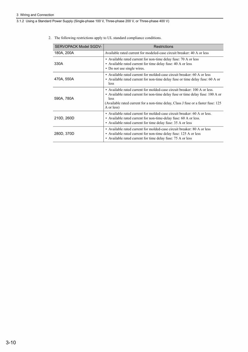
3 Wiring and Connection
3.1.2 Using a Standard Power Supply (Single-phase 100 V, Three-phase 200 V, or Three-phase 400 V)
3-10
2. The following restrictions apply to UL standard compliance conditions.
SERVOPACK Model SGDV- Restrictions
180A, 200A Available rated current for modeled-case circuit breaker: 40 A or less
330A• Available rated current for non-time delay fuse: 70 A or less• Available rated current for time delay fuse: 40 A or less• Do not use single wires.
470A, 550A• Available rated current for molded-case circuit breaker: 60 A or less• Available rated current for non-time delay fuse or time delay fuse: 60 A or
less
590A, 780A
• Available rated current for molded-case circuit breaker: 100 A or less. • Available rated current for non-time delay fuse or time delay fuse: 100 A or
less (Available rated current for a non-time delay, Class J fuse or a faster fuse: 125 A or less)
210D, 260D• Available rated current for molded-case circuit breaker: 60 A or less.• Available rated current for non-time-delay fuse: 60 A or less.• Available rated current for time delay fuse: 35 A or less
280D, 370D• Available rated current for molded-case circuit breaker: 80 A or less• Available rated current for non-time delay fuse: 125 A or less • Available rated current for time delay fuse: 75 A or less

3.1 Main Circuit Wiring
3-11
3
Wiri
ng
and
Con
nect
ion
3.1.3 Using the SERVOPACK with Single-phase, 200 V Power InputSome models of Σ-V series three-phase 200 V power input SERVOPACK can be used also with a single-phase 200 V power supply.
The following models support a single-phase 200-V power input.SGDV-R70A, -R90A, -1R6A, -2R8A, -5R5A
When using the SERVOPACK with single-phase, 200 V power input, set parameter Pn00B.2 to 1.
There is no need to change the parameter for a SGDV-120A11A008000 SERVOPACK because it uses a sin-gle-phase 200 V power supply.
(1) Parameter Setting
Single-phase Power Input Selection
(2) Main Circuit Power Input Terminals
Connect a single-phase 200 V power supply of the following specifications to L1 and L2 terminals.
The specifications of the power supplies other than the main circuit power supply are the same as for three-phase power supply input.
∗1. Do not use L3 terminal.∗2. The official model number is SGDV-120A11A008000.
Parameter Meaning When Enabled
Classification
Pn00B
n.0[Factory setting]
Enables use of three-phase power supply for three-phase SERVOPACK.
After restart Setup
n.1 Enables use of single-phase power supply for three-phase SERVOPACK.
WARNING• If single-phase 200 V is input to a SERVOPACK with a single-phase power input without changing the set-
ting of Pn00B.2 to 1 (single-phase power input), a main circuit cable open phase alarm (A.F10) will be detected.
• SERVOPACK models other than those for single-phase 200-V power input do not support single-phase power input. If a single-phase 200 V is input to the SERVOPACK that do not support single-phase power input, the main circuit cable open phase alarm (A.F10) will be detected.
• When using a single-phase 200 V power supply, the SGDV-R70A, -R90A, -1R6A, -2R8A, or -5R5A SER-VOPACK may not be able to produce the same servomotor torque-speed characteristics as using a three-phase 200 V power input. Refer to the diagram of each servomotor torque-speed characteristics in Σ-V Series Product Catalog (No.: KAEP S800000 42).
Terminal Symbols Name Model SGDV-A Specifications
L1, L2Main circuit power in-put terminals
R70, R90, 1R6, 2R8, 5R5 Single-phase 200 to 230 V, +10 to -15%, 50/60 Hz
120*2 Single-phase 220 to 230 V, +10 to -15%, 50/60 Hz
L3*1 – R70, R90, 1R6, 2R8, 5R5 None

3 Wiring and Connection
3.1.3 Using the SERVOPACK with Single-phase, 200 V Power Input
3-12
(3) Main Circuit Wire for SERVOPACKs
∗ The official model number is SGDV-120A11A008000.
(4) Wiring Example with Single-phase 200-V Power Supply Input
SERVOPACK with Single-phase, 200-V Power Supply
Applicable SERVOPACK Model: SGDV-R70A, -R90A, -1R6A, -2R8A, -5R5A, and -120A11A008000.
Terminal Symbols Name
Model SGDV-A (Unit: mm2)
R70 R90 1R6 2R8 5R5 120*
L1, L2 Main circuit power input termi-nals
HIV1.25 HIV2.0 HIV3.5
L1C, L2C Control power input terminals HIV1.25
U, V, W Servomotor connection termi-nals HIV1.25 HIV2.0
B1/ , B2External regenerative resistor connection terminals HIV1.25
Ground terminal HIV2.0 or larger
1PL
1KM
2KM 1SA
2SA
L1
0 V
1Ry
1D
2KM
L3
B2 B3
L2
U V W
M
1QF
R T
1FLT
+24 V
ENC
1 2
L1C 1KM
L2C
3SA
B1/ +
−
3
4
CN1
1KM 1Ry 1KM
ALM
ALM
1Ry
1PL 1SA 2SA 3SA 1D:
: Indicator lamp : Surge absorber : Surge absorber : Surge absorber Flywheel diode
1QF: Molded-case circuit breaker1FLT: Noise filter1KM: Magnetic contactor (for control power supply)2KM: Magnetic contactor (for main circuit power supply)1Ry: Relay
SERVOPACK SGDV-A
(For servo alarm display)
supply ON Servo power
supply OFF Servo power

3.1 Main Circuit Wiring
3-13
3
Wiri
ng
and
Con
nect
ion
(5) Power Supply Capacities and Power Losses
The following table shows SERVOPACK’s power supply capacities and power losses when using single-
phase 200 V power supply.
∗ The official model number is SGDV-120A11A008000.Note 1. SGDV-R70A, -R90A, -1R6A, and -2R8A SERVOPACKs do not have built-in regenerative resistors. If the regen-
erative energy exceeds the specified value, connect an external regenerative resistor between B1/ and B2.2. Regenerative resistor power losses are allowable losses. Take the following action if this value is exceeded.
• Remove the lead or shorting bar between terminals B2 and B3 on the SERVOPACK main circuit of SGDV-5R5A, -120A SERVOPACKs.
• Install an external regenerative resistor between external regenerative resistor connection terminals B1/ and B2.
3. External regenerative resistors are not included.
(6) How to Select Molded-case Circuit Breaker and Fuse Capacities
The following table shows the SERVOPACK’s current capacities and inrush current when using single-phase
Use these values as a basis for selecting the molded-case circuit breaker and fuse.
∗ The official model number is SGDV-120A11A008000.Note 1. To comply with the EU low voltage directive, connect a fuse to the input side as protection against accidents
caused by short-circuits. Select the fuse for the input side that are compliant with UL standards.The table above also provides the net values of current capacity and inrush current. Select a fuse and a molded-case circuit breaker which meet the breaking characteristics shown below.• Main circuit, control circuit: No breaking at three times the current values shown in the table for 5 s.• Inrush current: No breaking at the current values shown in the table for 20 ms.
2. The following restrictions apply to UL standard compliance conditions for SGDV-120A11A008000 SERVO-PACKs.
• Current rating when using molded-case circuit breaker: 40 A max.
Main Circuit Power Supply
Maximum Applicable
Servomotor Capacity
[kW]
SERVOPACKModel SGDV-
Power Supply Capacity per SERVOPACK
[kVA]
Output Current[Arms]
Main Circuit Power Loss[W]
Regenerative Resistor
Power Loss [W]
ControlCircuitPower Loss [W]
Total Power Loss [W]
Single-phase,200 V
0.05 R70A 0.2 0.66 5.2
–17
22.2
0.1 R90A 0.3 0.91 7.4 24.4
0.2 1R6A 0.7 1.6 13.7 30.7
0.4 2R8A 1.2 2.8 24.9 41.9
0.75 5R5A 1.9 5.5 52.7 8 77.7
1.5 120A* 4 11.6 68.2 10 22 100.2
Main Circuit Power Supply
Maximum Applicable Servomotor
Capacity[kW]
SERVOPACK ModelSGDV-
Power Supply Capacity per SERVOPACK
[kVA]
Current Capacity Inrush Current
Main Circuit[Arms]
Control Circuit[Arms]
Main Circuit[A0-p]
Control Circuit[A0-p]
Single-phase, 200 V
0.05 R70A 0.2 2
0.233
700.1 R90A 0.3 2
0.2 1R6A 0.7 3
0.4 2R8A 1.2 5
0.75 5R5A 1.9 933
1.5 120A* 4 16 0.25

3 Wiring and Connection
3.1.4 Using the SERVOPACK with a DC Power Input
3-14
3.1.4 Using the SERVOPACK with a DC Power Input
(1) Parameter Setting
When using a DC power supply, make sure to set the parameter Pn001.2 to 1 (DC power input supported) before inputting DC power.
Observe the following precautions.
(2) DC Power Supply Input Terminals for the Main and Control Circuits
Three-phase, 200 V for SGDV-A ( = R70, R90, 1R6, 2R8, 3R8, 5R5, 7R6, 120, 180, 200, 330)
Three-phase, 200-V for SGDV-A ( = 470, 550, 590, 780)
Three-phase, 400 V for SGDV-D ( = 1R9, 3R5, 5R4, 8R4, 120, 170, 210, 260, 280, 370)
Parameter Meaning When Enabled Classification
Pn001n.0 Enables use of AC power input.
After restart Setupn.1 Enables use of DC power input.
WARNING• Either AC or DC power can be input to the 200-V, 400-V SERVOPACKs. Always set Pn001.2 to 1 to spec-
ify a DC power input before inputting DC power. Only AC power can be input to the 100-V SERVOPACKs.If DC power is input without changing the parameter setting, the SERVOPACK’s internal elements will burn and may cause fire or damage to the equipment.
• With a DC power input, time is required to discharge electricity after the main power supply is turned OFF. A high residual voltage may remain in the SERVOPACK after the power supply is turned OFF. Be careful not to get an electric shock.
• Install fuses on the wires if DC power is used.• Servomotor returns a regenerated energy to the power supply. The SERVOPACK that can use a DC
power supply is not capable of processing the regenerated energy. Provide measures to process the regenerated energy on the power supply.
• With a DC power input, connect an external inrush current limit circuit.Failure to observe this caution may result in damage to the equipment.
Terminal Symbols Name Specifications
B1/ Main circuit positive terminal 270 to 320 VDC
2 Main circuit negative terminal 0 VDC
L1C, L2C Control power input terminal 200 to 230 VAC
Terminal Symbols Name Specifications
B1/ Main circuit positive terminal 270 to 320 VDC
Main circuit negative terminal 0 VDC
L1C, L2C Control power input terminal 200 to 230 VAC
Terminal Symbols Name Specifications
B1/ Main circuit positive terminal 513 to 648 VDC
2 Main circuit negative terminal 0 VDC
24 V, 0 V Control power input terminal 24 VDC ±15%

3.1 Main Circuit Wiring
3-15
3
Wiri
ng
and
Con
nect
ion
(3) Wiring Example with DC Power Supply Input 200-V SERVOPACK SGDV-A
∗ Terminal names differ depending on model of SERVOPACK. Refer to (2) DC Power Supply Input Terminals for the Main and Control Circuits.
400-V SERVOPACK SGDV-D
∗ Terminal names differ depending on model of SERVOPACK. Refer to (2) DC Power Supply Input Terminals for the Main and Control Circuits.
1QF: Molded-case circuit breaker1FLT: Noise filter1KM: Magnetic contactor (for control power supply)2KM: Magnetic contactor (for main circuit power supply)1Ry: Relay
1PL: Indicator lamp1SA: Surge absorber2SA: Surge absorber3SA: Surge absorber1D: Flywheel diode
1PL
1KM
2KM1SA
2SA
L1CL2C
B1/2
+*1FU2KM
ENC
UVW
M
0 V
1Ry
1D
+24 V
1KM
AC/DC
1QF
R S T
3SA
+
−
3
4
CN1
1Ry
1KM1Ry1KM
ALM
ALM
1FLT
SGDV-A
(For servoalarm display)
supply ONServo power
supply OFFServo power
200-V SERVOPACK
24 V 0 V
B1
400-V SERVOPACKSGDV-D
2
1FU 2KM
ENC
U V W
M
0 V
1Ry
1D
+24 V
AC/DC
1QF
R S T
*
3SA
AC/DC
1PL
1KM
2KM 1SA
2SA
1KM
+
−
3
4
CN1
1Ry
1KM
1Ry 1KM
ALM
ALM
1FLT
1QF: Molded-case circuit breaker1FLT: Noise filter1KM: Magnetic contactor (for control power supply)2KM: Magnetic contactor (for main circuit power supply)1Ry: Relay
1PL: Indicator lamp1SA: Surge absorber2SA: Surge absorber3SA: Surge absorber1D: Flywheel diode
(For servo alarm display)
supply ON Servo power
supply OFF Servo power
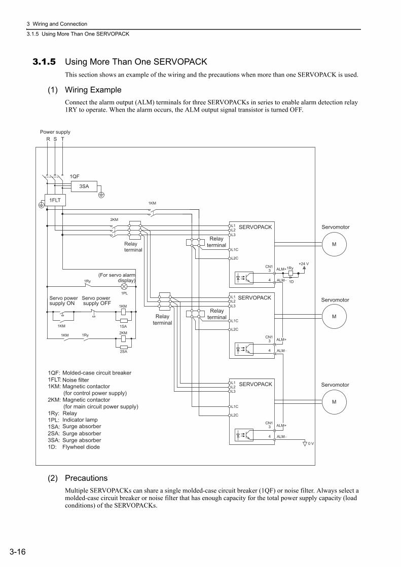
3 Wiring and Connection
3.1.5 Using More Than One SERVOPACK
3-16
3.1.5 Using More Than One SERVOPACKThis section shows an example of the wiring and the precautions when more than one SERVOPACK is used.
(1) Wiring Example
Connect the alarm output (ALM) terminals for three SERVOPACKs in series to enable alarm detection relay 1RY to operate. When the alarm occurs, the ALM output signal transistor is turned OFF.
(2) Precautions
Multiple SERVOPACKs can share a single molded-case circuit breaker (1QF) or noise filter. Always select a molded-case circuit breaker or noise filter that has enough capacity for the total power supply capacity (load conditions) of the SERVOPACKs.
R S T
1QF
2KM
1Ry +24 V
L1 L2 L3
L1C
0 V
L2C
1FLT
M
L1 L2 L3
L1 L2 L3
L1C
1D
L2C
M
M
L1C
L2C
3SA
1KM
1PL
1KM
2KM
1SA
2SA
3
4
CN1
1KM
1Ry 1KM
ALM+
ALM−
3
4
CN1
ALM−
3
4
CN1
ALM−
1Ry
ALM+
ALM+
SERVOPACK
Servomotor
Servomotor
Servomotor
Relay terminal
Relay terminal
Relay terminal
1QF: 1FLT: 1KM: Magnetic contactor (for control power supply) 2KM: (for main circuit power supply) 1Ry: 1PL: 1SA: 2SA:3SA:1D:
Molded-case circuit breaker Noise filter
Relay
Magnetic contactor
Indicator lamp Surge absorber
SERVOPACK
SERVOPACK
Surge absorber Surge absorber Flywheel diode
supply ON
Power supply
Relay terminal
(For servo alarm display)
Servo power supply OFF Servo power

3.1 Main Circuit Wiring
3-17
3
Wiri
ng
and
Con
nect
ion
3.1.6 General Precautions for Wiring
To ensure safe, stable application of the servo system, observe the following precautions when wiring.• Use the connection cables specified in the Σ-V Series Product Catalog (No.: KAEP S800000 42). Design
and arrange the system so that each cable will be as short as possible.• Observe the following precautions when wiring the ground.
• Use a cable as thick as possible (at least 2.0 mm2).• Grounding to a resistance of 100 Ω or less for 100-V, 200-V SERVOPACKs, 10 Ω or less for 400-V
SERVOPACKs is recommended.• Be sure to ground at only one point.• Ground the servomotor directly if the servomotor is insulated from the machine.
• Do not apply bending stress or tension to the signal cables when you handle them. The core wires are very thin (0.2 mm2 or 0.3 mm2).
CAUTION• Use shielded twisted-pair cables or screened unshielded twisted-pair cables for I/O signal cables and
encoder cables.• The maximum wiring length is 3 m for I/O signal cables, 50 m for encoder cables or servomotor main cir-
cuit cables, and 10 m for control power supply cables for the SERVOPACK with a 400-V power supply (+24 V, 0 V).
•
• Use a molded-case circuit breaker (1QF) or fuse to protect the main circuit.
The SERVOPACK connects directly to a commercial power supply; it is not isolated through a transformer or other device.Always use a molded-case circuit breaker (1QF) or fuse to protect the servo system from accidents involving different power system voltages or other accidents.
• Install a ground fault detector.
The SERVOPACK does not have a built-in protective circuit for grounding. To config-ure a safer system, install a ground fault detector against overloads and short-circuit-ing, or install a ground fault detector combined with a molded-case circuit breaker.
• Do not turn the power ON and OFF more than necessary.
• Do not use the SERVOPACK for applications that require the power to turn ON and OFF frequently. Such applications will cause elements in the SERVOPACK to dete-riorate.
• As a guideline, at least one hour should be allowed between the power being turned ON and OFF once actual operation has been started.

3 Wiring and Connection
3.2.1 I/O Signal (CN1) Names and Functions
3-18
3.2 I/O Signal ConnectionsThis section describes the names and functions of I/O signals (CN1). Also connection examples by control method are shown.
3.2.1 I/O Signal (CN1) Names and FunctionsThe following table shows the names and functions of I/O signals (CN1).
(1) Input Signals
Note 1. You can change the allocations of the input signals (/SI0 to /SI6). For details, refer to 3.3.1 Input Signal Alloca-tions.
2. If the Forward run prohibited/ Reverse run prohibited function is used, the SERVOPACK is stopped by software controls, not by electrical or mechanical means. If the application does not satisfy the safety requirements, add an external circuit for safety reasons as required.
Signal Pin No. Name FunctionRefer-ence
Section
P-OT(/SI1)N-OT(/SI2)
78
Forward run prohibited,Reverse run prohibited
With overtravel prevention: Stops servomotor when movable part travels beyond the allowable range of motion.
4.3.1
/DEC(/SI3)
9Homing decelerationswitch signal
Connects the deceleration limit switch for homing. −
/EXT 1(/SI4)/EXT 2(/SI5)/EXT 3(/SI6)
101112
External latch signal 1External latch signal 2External latch signal 3
Connects the external signals that latch the current feedback pulse counter.
−
/SI0 13 General-purpose input signal
Used for general-purpose input.Monitored in the I/O monitor field of MECHATROLINK-II. −
+24VIN 6Control power supply for sequence signal
Control power supply input for sequence signals.Allowable voltage fluctuation range: 11 to 25 VNote: The 24 VDC power supply is not included.
3.4.1
BAT (+)BAT (-)
1415
Battery (+) input signalBattery (−) input signal
Connecting pin for the absolute encoder backup battery.Do not connect when the encoder cable with the battery case is used.
3.6.24.7.1
/P-CL/N-CL
Can be allocated
Forward external torque limitReverse external torque limit
The allocation of an input signal to a pin can be changed in accordance with the function required.
−

3.2 I/O Signal Connections
3-19
3
Wiri
ng
and
Con
nect
ion
(2) Output Signals
Note: You can change the allocations of the output signals (/SO1 to /SO3). For details, refer to 3.3.2 Output Signal Alloca-tions.
3.2.2 Safety Function Signal (CN8) Names and FunctionsThe following table shows the terminal layout of safety function signals (CN8).
∗ Do not use pins 1 and 2 because they are connected to the internal circuits.
Signal Pin No. Name FunctionRefer-ence
Section
ALM+ALM-
34
Servo alarm output signal Turns OFF when an error is detected. −
/BK+(/SO1+)/BK-(/SO1-)
1
2Brake interlock signal
Controls the brake. The brake is released when the signal turns ON (closed).Allocation can be changed to general-purpose output signals (/SO1+, /SO1-).
4.3.2
/SO2+/SO2-/SO3+/SO3-
23242526
General-purposeoutput signal
Used for general-purpose output.Note: Set the parameter to allocate a function.
−
/COIN/V-CMP/TGON/S-RDY/CLT/VLT/WARN/NEAR
Can be allocated
Positioning comple-tionSpeed coincidence detectionRotation detection servo readyTorque limitSpeed limit detectionWarningNear
The allocation of an output signal to a pin can be changed in accordance with the function required. −
PAO/PAO
1718
Phase-A signal
Encoder output pulse signals with 90° phase differential4.4.44.7.5
PBO/PBO
1920
Phase-B signal
PCO/PCO
2122
Phase-C signal Origin pulse output signal
SG 16 Signal ground Connects to the 0 V pin on the control circuit of the host con-troller.
−
FG Shell Frame ground Connected to frame ground if the shielded wire of the I/O sig-nal cable is connected to the connector shell. −
Signal Name Pin No. Function
/HWBB1+ 4Hard wire baseblock input 1 For hard wire baseblock input.
Baseblock (motor current off) when OFF.
/HWBB1- 3
/HWBB2+ 6Hard wire baseblock input 2
/HWBB2- 5
EDM1+ 8Monitored circuit status output 1
ON when the /HWBB1 and the/HWBB2 signals are input and the SERVOPACK enters a baseblock state.EDM1- 7
– 1* –
– 2* –

3 Wiring and Connection
3.2.3 Example of I/O Signal Connections
3-20
3.2.3 Example of I/O Signal ConnectionsThe following diagram shows a typical connection example.
∗1. represents twisted-pair wires.∗2. Connect when using an absolute encoder. When the encoder cable with the battery case is connected, do not connect
a backup battery.∗3. The 24-VDC power supply is not included. Use a 24-VDC power supply with double insulation or reinforced insula-
tion.∗4. When using a safety function device, refer to 4.9 Safety Function. When not using a safety function device, leave the
safety function’s jumper connector that is included with the SERVOPACK inserted in CN8.∗5. Always use line receivers to receive the output signals.Note: The functions allocated to the input signals /DEC, P-OT, N-OT, /EXT1, /EXT2, and /EXT3 and the output signals
/SO1, /SO2, and /SO3 can be changed by using the parameters. For details, refer to 3.3.1 Input Signal Allocations and 3.3.2 Output Signal Allocations.
SO1+ / BK+
SO1- / BK-/SO2+
/SO2-
/SO3+
ALM+
ALM-
1
223
24
3
4+24VIN+24 V 3.3 kΩ6
8
10
9
11
12
/SI0
P-OT
N-OT
/DEC
/EXT1
/EXT2
/EXT3
13
7
/SO3-
SERVOPACK
25
26
16 SG
*1
*2
*3
PBO
PCO
/PBO
PAO/PAO
/PCO21
1718
1920
22
EDM1+
EDM1-
FG
/HWBB1+
/HWBB1-
/HWBB2+
/HWBB2-
24 V
0 V
Safety function device*4
CN8
6
3
4
5
8
7
Encoder output pulse phase A
Encoder output pulse phase B
Encoder output pulse phase C
Applicable line receiver: SN75ALS175 or MC3486 manufactured by Texas Instruments or the equivalent
Photocoupler outputMax. allowable voltage: 30 VDCMax. allowable current: 50 mA DC
Connect shield to connector shell.
Connectorshell
SERVOPACK
Switch
Fuse
General-purpose
Servo alarm output(OFF for an alarm)
Brake (Brake released when ON)
Reverse run prohibited(Prohibited when OFF)
Forward run prohibited(Prohibited when OFF)
External latch signal 1(Latched when ON)
External latch signal 2(Latched when ON)
External latch signal 3(Latched when ON)
Homing decelerationswitch(Decelerated when ON)
Control power supply for sequence signal
Backup battery(2.8 to 4.5 V)
*5
*5
*5
14
15
BAT (+)
BAT (-)+-

3.3 I/O Signal Allocations
3-21
3
Wiri
ng
and
Con
nect
ion
3.3 I/O Signal AllocationsThis section describes the I/O signal allocations.
3.3.1 Input Signal Allocations
Input signals are allocated as shown in the following table.
Refer to the Interpreting the Input Signal Allocation Tables and change the allocations accordingly.
<Interpreting the Input Signal Allocation Tables>
• Inverting the polarity of the forward run prohibited and reverse run prohibited signals from the factory setting will prevent the overtravel function from working in case of sig-nal line disconnections or other failures.If this setting is absolutely necessary, check the operation and confirm that there are no safety problems.
• When two or more signals are allocated to the same input circuit, input signal level is valid for all allocated signals, resulting in an unexpected machine operation.
Input Signal Names and Parameters
Validity Level
Input Signal
CN1 Pin Numbers
Connection Not Required
(SERVOPACK judges the connec-
tion)
13 7 8 9 10 11 12 Always ON
Always OFF
Forward Run ProhibitedPn50A.3
H P-OT 0 1 2 3 4 5 67 8
L /P-OT 9 A B C D E F
Level at which input signalallocations are valid.
The parameter set values to be used are shown. Signals are allocated to CN1 pins according to the selected set values. Values in cells in bold lines are the factory settings.
If always ON (7) or always OFF (8) is set, signals will be processed in the SERVOPACK, which will eliminate the need for wiring changes.
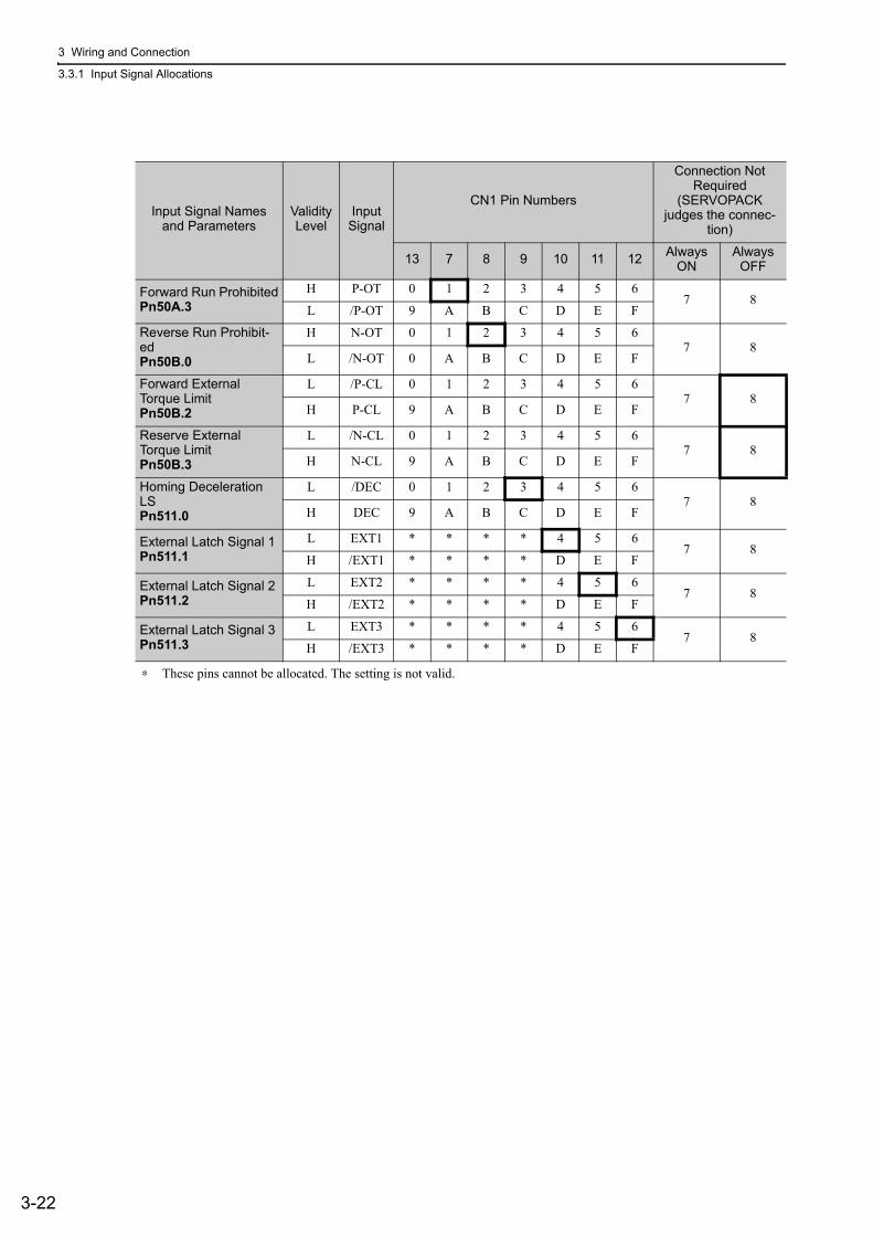
3 Wiring and Connection
3.3.1 Input Signal Allocations
3-22
∗ These pins cannot be allocated. The setting is not valid.
Input Signal Names and Parameters
Validity Level
Input Signal
CN1 Pin Numbers
Connection Not Required
(SERVOPACK judges the connec-
tion)
13 7 8 9 10 11 12 Always ON
Always OFF
Forward Run ProhibitedPn50A.3
H P-OT 0 1 2 3 4 5 67 8
L /P-OT 9 A B C D E F
Reverse Run Prohibit-edPn50B.0
H N-OT 0 1 2 3 4 5 67 8
L /N-OT 0 A B C D E F
Forward External Torque LimitPn50B.2
L /P-CL 0 1 2 3 4 5 67 8
H P-CL 9 A B C D E F
Reserve External Torque LimitPn50B.3
L /N-CL 0 1 2 3 4 5 67 8
H N-CL 9 A B C D E F
Homing Deceleration LS Pn511.0
L /DEC 0 1 2 3 4 5 67 8
H DEC 9 A B C D E F
External Latch Signal 1Pn511.1
L EXT1 * * * * 4 5 67 8
H /EXT1 * * * * D E F
External Latch Signal 2Pn511.2
L EXT2 * * * * 4 5 67 8
H /EXT2 * * * * D E F
External Latch Signal 3Pn511.3
L EXT3 * * * * 4 5 67 8
H /EXT3 * * * * D E F

3.3 I/O Signal Allocations
3-23
3
Wiri
ng
and
Con
nect
ion
3.3.2 Output Signal Allocations
Output signals are allocated as shown in the following table.
Refer to the Interpreting the Output Signal Allocation Tables and change the allocations accordingly.
<Interpreting the Output Signal Allocation Tables>
• The signals not detected are considered as "Invalid." For example, Positioning Com-pletion (/COIN) signal in speed control is "Invalid."
• Inverting the polarity of the brake signal (/BK), i.e. positive logic, will prevent the hold-ing brake from working in case of its signal line disconnection.If this setting is absolutely necessary, check the operation and confirm that there are no safety problems.
• When two or more signals are allocated to the same output circuit, a signal is output with OR logic circuit.
Output Signal Names and Parameters
Output SignalCN1 Pin Numbers Invalid
(not use)1 (2) 23 (24) 25 (26)
Positioning CompletionPn50E.0 /COIN 1 2 3 0
Speed Coincidence DetectionPn50E.1
/V-CMP 1 2 3 0
Rotation DetectionPn50E.2 /TGON 1 2 3 0
Servo ReadyPn50E.3 /S-RDY 1 2 3 0
Torque Limit DetectionPn50F.0 /CLT 1 2 3 0
Speed Limit DetectionPn50F.1 /VLT 1 2 3 0
BrakePn50F.2 /BK 1 2 3 0
WarningPn50F.3 /WARN 1 2 3 0
NearPn510.0 /NEAR 1 2 3 0
Pn512.0=1 Polarity inversion of CN1-1(2) 0(Not invert at
factory setting)Pn512.1=1 Polarity inversion of CN1-23(24)
Pn512.2=1 Polarity inversion of CN1-25(26)
Output SignalCN1 Pin Numbers Invalid
not use1 (2) 23 (24) 25 (26)Brake Pn50F.2 /BK 1 2 3 0
The parameter set values to be used are shown. Signals are allocated to CN1 pins according to the selected set values. Values in cells in bold lines are the factory settings.
Output Signal Names and Parameters

3 Wiring and Connection
3.4.1 Sequence Input Circuit
3-24
3.4 Examples of Connection to Host ControllerThis section shows examples of SERVOPACK I/O signal connection to the host controller.
3.4.1 Sequence Input Circuit
(1) Photocoupler Input Circuit
CN1 connector terminals 6 to 13 are explained below.
The sequence input circuit interface is connected through a relay or open-collector transistor circuit. When connecting through a relay, use a low-current relay. If a low-current relay is not used, a faulty contact may result.
Note: The 24 VDC external power supply capacity must be 50 mA minimum.
The SERVOPACK’s input circuit uses bidirectional photocoupler. Select either the sink circuit or the source circuit according to the specifications required for each machine.
Note 1. The connection examples in 3.2.3 Example of I/O Signal Connections are sink circuit connections.2. The ON/OFF polarity differs between when a sink circuit is connected and when a source circuit is connected.
Relay Circuit Example Open-collector Circuit Example
Sink Circuit Source Circuit
Input Signal Polarities Input Signal Polarities
Signal Level Voltage Level
Contact Signal Level Voltage Level
Contact
ON Low (L) level 0 V Close ON High (H)
level 24 V Close
OFFHigh (H)
level 24 V Open OFFLow (L)
level 0 V Open
3.3 kΩ
/DEC, etc.
SERVOPACK
24 VDC +24VIN 24 VDC 3.3 kΩ
/DEC, etc.
SERVOPACK
+24VIN
24 V+ − SERVOPACK input
24 V+ − SERVOPACK input

3.4 Examples of Connection to Host Controller
3-25
3
Wiri
ng
and
Con
nect
ion
(2) Safety Input Circuit
As for wiring input signals for safety function, input signals make common 0 V. It is necessary to make an input signal redundant.
3.4.2 Sequence Output Circuit
Three types of SERVOPACK output circuit are available.
(1) Photocoupler Output Circuit
Photocoupler output circuits are used for servo alarm (ALM), servo ready (/S-RDY), and other sequence out-put signal circuits. Connect a photocoupler output circuit through a relay or line receiver circuit.
Note: The maximum allowable voltage and current range of the photocoupler output circuit are as follows:• Maximum allowable voltage: 30 VDC• Current range: 5 to 50 mA DC
Input Signal Connection Example
24-V power supplySwitch
Fuse
/HWBB1+ 4
3/HWBB1-
/HWBB2+
/HWBB2-
3.3 kΩ
CN8
3.3 kΩ
SERVOPACK
6
5
3.3 kΩ
3.3 kΩ
Incorrect wiring or incorrect voltage application to the output circuit may cause short-cir-cuit.
If a short-circuit occurs as a result of any of these causes, the holding brake will not work. This could damage the machine or cause an accident resulting in death or injury.
Relay Circuit Example Line Receiver Circuit Example
0 V
Relay5 to 24 VDCSERVOPACK SERVOPACK 5 to 12 VDC

3 Wiring and Connection
3.4.2 Sequence Output Circuit
3-26
(2) Line Driver Output Circuit
CN1 connector terminals, 17-18 (phase-A signal), 19-20 (phase-B signal), and 21-22 (phase-C signal) are explained below.
These terminals output the following signals via the line-driver output circuits.
• Output signals for which encoder serial data is converted as two phases pulses (PAO, /PAO, PBO, /PBO)• Origin pulse signals (PCO, /PCO)
Connect the line-driver output circuit through a line receiver circuit at the host controller.
(3) Safety Output Circuit
The external device monitor (EDM1) for safety output signals is explained below.
A configuration example for the EDM1 output signal is shown in the following diagram.
Specifications
Electrical characteristics of EDM1 signal are as follows.
Line Receiver Circuit Example
SERVOPACK Host Controller Applicable line receiver: SN75ALS175 or the equivalent
220 to 470 Ω
EDM1+
EDM1-
0 V
8
7
CN8 24 V Power Supply SERVOPACK Host controller
Type Signal Name Pin No. Output Status Meaning
Output EDM1CN8-8CN8-7
ONBoth the /HWBB1 and /HWBB2 signals are working nor-mally.
OFF The /HWBB1 signal, the /HWBB2 signal, or both are not working normally.
Items Characteristic Remarks
Maximum Allowable Voltage 30 VDC −
Maximum Allowable Current 50 mADC −
Maximum Voltage Drop at ON 1.0 V Voltage between EDM1+ to EDM1- at current is 50 mA.
Maximum Delay Time 20 ms Time from the change in /HWBB1 or /HWBB2 until the change in EDM1.

3.5 Wiring MECHATROLINK-II Communications
3-27
3
Wiri
ng
and
Con
nect
ion
3.5 Wiring MECHATROLINK-II CommunicationsThe following diagram shows an example of connections between a host controller and a SERVOPACK using MECHATROLINK-II communications cables (CN6A, CN6B).
Note 1. The length of the cable between stations (L1, L2 ... Ln) must be 0.5 m or more.2. The total cable length must be L1 + L2 ... + Ln ≤ 50.3. When multiple SERVOPACKs are connected by MECHATROLINK-II communications cable, a terminator must
be installed at the final SERVOPACK.
Ln
L1
L2
Terminator
DC24V
DC 0V
MP2300YASKAWA
TEST
Opt
ion
Opt
ion
RDY
ALMTX
RUN
ERRBAT
MONCNFG
INTSUP
STOP
SW1
OFF ON
BATTERY
CPU I/O
M-I/II
218IF-01ERR
COL
RX
RUN
STRX
TX
INITTEST
ONOFF
PORT
10Base-T
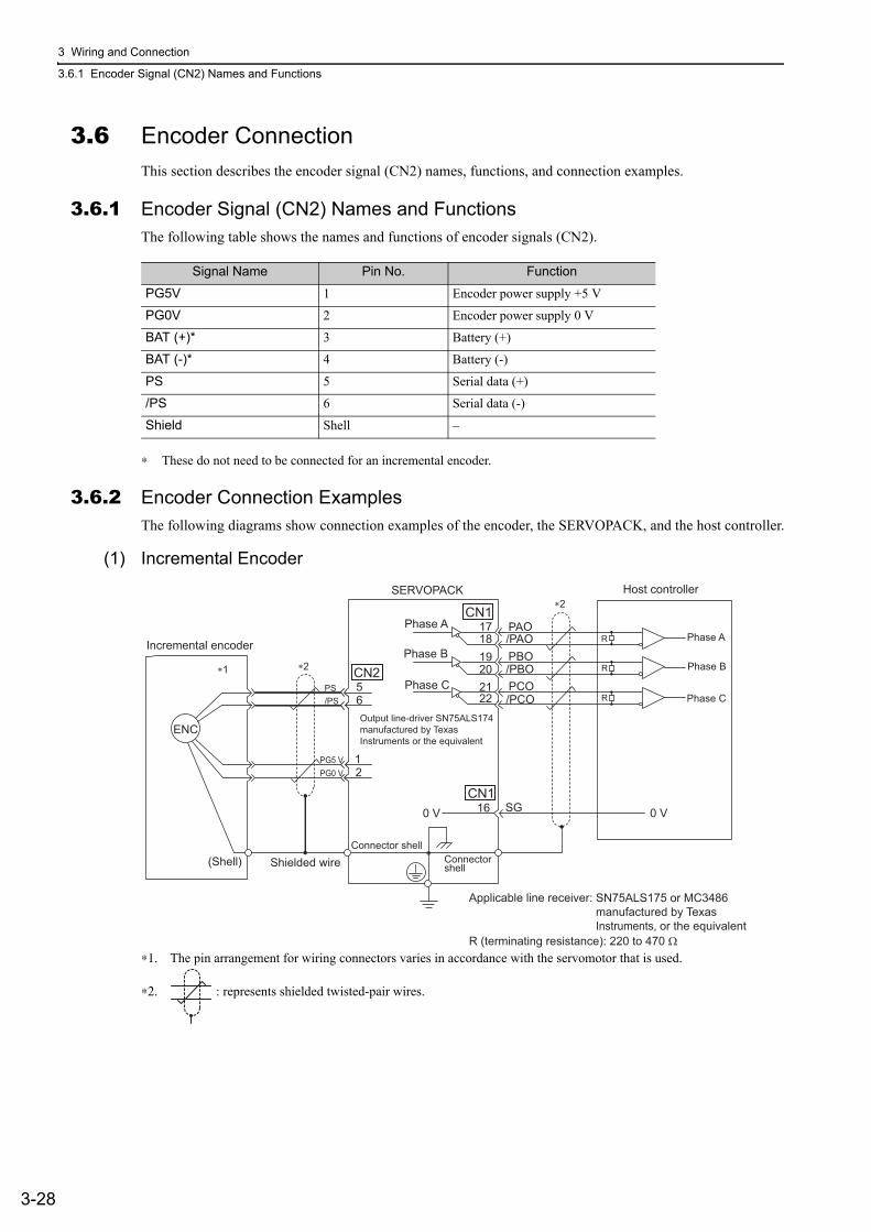
3 Wiring and Connection
3.6.1 Encoder Signal (CN2) Names and Functions
3-28
3.6 Encoder ConnectionThis section describes the encoder signal (CN2) names, functions, and connection examples.
3.6.1 Encoder Signal (CN2) Names and FunctionsThe following table shows the names and functions of encoder signals (CN2).
∗ These do not need to be connected for an incremental encoder.
3.6.2 Encoder Connection ExamplesThe following diagrams show connection examples of the encoder, the SERVOPACK, and the host controller.
(1) Incremental Encoder
∗1. The pin arrangement for wiring connectors varies in accordance with the servomotor that is used.
∗2. : represents shielded twisted-pair wires.
Signal Name Pin No. Function
PG5V 1 Encoder power supply +5 V
PG0V 2 Encoder power supply 0 V
BAT (+)* 3 Battery (+)
BAT (-)* 4 Battery (-)
PS 5 Serial data (+)
/PS 6 Serial data (-)
Shield Shell –
19
0 V SG 16
PA O /P AO PBO /PBO PCO /PCO
1 2
5 6
CN2
1718
202122
ENC
CN1
CN1
PS /PS
PG5 VPG0 V
0 V
R
R
R
Incremental encoder
Shielded wire(Shell) Connector shell
Connector shell
Output line-driver SN75ALS174 manufactured by Texas Instruments or the equivalent
Phase A Phase A
Phase B Phase B
Phase C Phase C
SERVOPACK Host controller
∗1 ∗2
∗2
R (terminating resistance): 220 to 470 Ω
Applicable line receiver: SN75ALS175 or MC3486 manufactured by TexasInstruments, or the equivalent

3.6 Encoder Connection
3-29
3
Wiri
ng
and
Con
nect
ion
(2) Absolute Encoder
∗1. The pin arrangement for wiring connectors varies in accordance with the servomotor that is used.
∗2. : represents shielded twisted-pair wires.
∗3. When using an absolute encoder, provide power by installing an encoder cable with a JUSP-BA01-E Battery Case or install a battery on the host controller.
• When Installing a Battery on the Encoder CableUse the encoder cable with a battery case that is specified by Yaskawa.For details, refer to the Σ-V Series Product Catalog (Catalog No.: KAEP S800000 42).
• When Installing a Battery on the Host ControllerInsert a diode near the battery to prevent reverse current flow.
/PCO
ENC
3 4
1415
BAT BAT
(+) (-)
CN2
171819202122
CN1 PA O
/P AO PBO
/PBO PCO
CN1
5 6
1 2
PG5VPG0V
PS /PS
BAT(+) BAT(-)
R
R
R
0 V SG16 0 V
+-
Absolute encoder
(Shell)
SERVOPACK
Phase A
Phase B
Phase C
Connector shell
Connector shell
∗2
∗3
∗2 ∗1
Phase A
Phase B
Phase C
Host controller
Battery
Output line-driver SN75ALS174 manufactured by Texas Instruments or the equivalent
R (terminating resistance): 220 to 470 Ω
Applicable line receiver: SN75ALS175 or MC3486 manufactured by TexasInstruments, or the equivalent
Circuit Example
+- Battery

3 Wiring and Connection
3.7.1 Connecting Regenerative Resistors
3-30
3.7 Connecting Regenerative ResistorsIf the built-in regenerative resistor is insufficient, connect an external regenerative resistor by one of the fol-lowing methods and set the regenerative resistor capacity (Pn600). As for precautions on selecting a regenera-
tive resistor and its specifications, refer to Σ-V Series Product Catalog (No.: KAEP S800000 42).
3.7.1 Connecting Regenerative ResistorsThe following instructions show how to connect the regenerative resistors and SERVOPACKs.
(1) SERVOPACKs: Model SGDV-R70F, -R90F, -2R1F, -2R8F, -R70A, -R90A, -1R6A, -2R8A
Connect an external regenerative resistor between the B1/ and B2 terminals on the SERVOPACK. After connecting a resistor, select the capacity. For more information on how to set the capacity of regenerative resistors, refer to 3.7.2 Setting Regenerative Resistor Capacity.
(2) SERVOPACKs: Model SGDV-3R8A, -5R5A, -7R6A, -120A, -180A, -200A, -330A, -1R9D, -3R5D, -5R4D, -8R4D, -120D, -170D
Disconnect the wiring between the SERVOPACK’s B2 and B3 terminals and connect an external regenerative resistor between the B1/ and B2 terminals. After connecting the resistor, select the capacity. For more infor-mation on how to set the capacity of regenerative resistors, refer to 3.7.2 Setting Regenerative Resistor Capac-ity.
Note: Be sure to take out the lead wire between the B2 and B3 terminals.
WARNING• Be sure to connect the regenerative resistor correctly. Do not short-circuit between B1/ and B2.
Doing so may result in fire or damage to the regenerative resistor or SERVOPACK.
Enlarged View
Enlarged View

3.7 Connecting Regenerative Resistors
3-31
3
Wiri
ng
and
Con
nect
ion
(3) SERVOPACKs: Model SGDV-470A, -550A, -590A, -780A, -210D, -260D, -280D, -370D
No built-in regenerative resistor is provided, so the external regenerative resistor is required. The regenerative resistor units are as follows:
Note: The regenerative resistor unit is constructed from a number of resistors.
Connect the B1/ and B2 terminals of the SERVOPACK to the R1 and R2 terminals of the regenerative resis-tor unit.
Use Pn600 at the factory setting when you use a Yaskawa regenerative resistor unit. Set Pn600 when using a non-YASKAWA external regenerative resistor.
Main Circuit Power Supply
Applicable SERVOPACK Model
SGDV-
Applicable Regenerative Resistor Unit
Resis-tance (Ω) Specifications
Three-phase 200 V
470A JUSP-RA04-E 6.25 Four 25 Ω (220 W) resistors are connected in parallel.
550A, 590A, 780A JUSP-RA05-E 3.13 Eight 25 Ω (220 W) resistors are connected in parallel.
Three-phase 400 V
210D, 260D JUSP-RA18-E 18 Two series of two 18 Ω (220 W) resistors each are connected in parallel.
280D, 370D JUSP-RA19-E 14.25 Four series of two 28.5 Ω (220 W) resistors each are connected in parallel.
Regenerative Resistor UnitJUSP-RA-E
SERVOPACK

3 Wiring and Connection
3.7.2 Setting Regenerative Resistor Capacity
3-32
3.7.2 Setting Regenerative Resistor CapacityWhen a non-Yaskawa external regenerative resistor is connected, always set Pn600 (Regenerative Resistor Capacity) to the resistor capacity.
Be sure to set the regenerative resistor capacity (Pn600) to a value that is in accordance with the allowable capacity of the actual external regenerative resistor being used.
The setting will vary with the cooling method of external regenerative resistor:
• For natural convection cooling: Set the value to a maximum 20% of the actually installed regenerative resistor capacity (W).
• For forced convection cooling: Set the value to a maximum 50% of the actually installed regenerative resistor capacity (W).
Example: Set 20 W (100 W × 20%) for the 100-W external regenerative resistor with natural convection cooling method: Pn600 = 2 (unit: 10 W)
Note 1. If Pn600 is not set to the optimum value, alarm A.320 will occur.2. When set to the factory setting (Pn600 = 0), the SERVOPACK’s built-in resistor or Yaskawa’s regenerative resis-
tor unit has been used.
WARNING• If Pn600 is set to 0 when a non-Yaskawa external regenerative resistor is connected, regenerative over-
load alarms (A.320) may not be detected. If the regenerative overload alarm (A.320) is not detected cor-rectly, the external regenerative resistor may be damaged and an injury or fire may result.
Pn600
Regenerative Resistor Capacity Classification
Setting Range Unit Factory Setting When Enabled
0 to SERVOPACK capacity
10 W 0 Immediately Setup
• When the external regenerative resistors for power are used at the rated load ratio, the resistor temperature increases to between 200 and 300°C. The resistors must be used at or below the rated values. Check with the manufacturer for the resistor’s load characteristics.
• For safety, use the external regenerative resistors with thermoswitches.
Speed Position Torque

3.8 Noise Control and Measures for Harmonic Suppression
3-33
3
Wiri
ng
and
Con
nect
ion
3.8 Noise Control and Measures for Harmonic SuppressionThis section describes the wiring for noise control and the DC reactor for harmonic suppression.
3.8.1 Wiring for Noise Control
The SERVOPACK uses microprocessors. Therefore it may receive switching noise from peripheral devices.
To prevent the noise from the SERVOPACK or the peripheral devices from causing a malfunction of any one of these devices, take the following precautions against noise as required.
• Position the input reference device and noise filter as close to the SERVOPACK as possible.• Always install a surge absorber in the relay, solenoid and electromagnetic contactor coils.• Do not bundle or run the main circuit cables together with the I/O signal cables or the encoder cables in the
same duct. Keep the main circuit cables separated from the I/O signal cables and the encoder cables with a gap of at least 30 cm.
• Do not use the same power supply as electric welders, electrical discharge machines, and similar devices. If the SERVOPACK is placed near equipment that generates high-frequency noise, install a noise filter on the input side of the main circuit power supply cable and control power supply cable, even if the same power supply is not used. Refer to (1) Noise Filter for the noise filter connection method.
• Take the grounding measures correctly. As for the grounding, refer to (2) Correct Grounding.
• Because the SERVOPACK is designed as an industrial device, it provides no mecha-nism to prevent noise interference.
• The SERVOPACK uses high-speed switching elements in the main circuit. Therefore peripheral devices may receive switching noise. If the equipment is to be used near private houses or if radio interference is a problem, take countermeasures against noise.
• If installation conditions by the EMC directive must be met, refer to 2.4 EMC Installa-tion Conditions in Σ-V Series User's Manual Setup Rotational Motor (No.: SIEP S800000 43).

3 Wiring and Connection
3.8.1 Wiring for Noise Control
3-34
(1) Noise Filter
The SERVOPACK has a built-in microprocessor (CPU), so protect it from external noise as much as possible by installing a noise filter in the appropriate place.
The following is an example of wiring for noise control.
∗1. For ground wires connected to the ground plate, use a thick wire with a thickness of at least 2.0 mm2 (preferably, plain stitch cooper wire).
∗2. should be twisted-pair wires.∗3. When using a noise filter, follow the precautions in 3.8.2 Precautions on Connecting Noise Filter.
(2) Correct Grounding
Take the following grounding measures to prevent the malfunction due to noise.
Grounding the Motor Frame
Always connect servomotor frame terminal FG to the SERVOPACK ground terminal . Also be sure to ground the ground terminal .
If the servomotor is grounded via the machine, a switching noise current will flow from the SERVOPACK main circuit through servomotor stray capacitance. The above grounding is required to prevent the adverse effects of switching noise.
Noise on the I/O Signal Cable
If the I/O signal cable receives noise, ground the 0 V line (SG) of the I/O signal cable. If the servomotor main circuit cable is accommodated in a metal conduit, ground the conduit and its junction box. For all grounding, ground at one point only.
U
WV
L2
L1
L3
L2CL1C
CN2
CN1
ENC
(FG)M
SERVOPACKServomotor
Operation relaysequenceSignal generationcircuit (not included)
DCpower
(Ground plate)
2.0 mmmin.
2
200 VAC
Noise filter ∗3
∗3 ∗2
2.0 mm2
min .
Ground: Ground to an independent ground
Noisefilter
2.0 mm2
min .
∗1

3.8 Noise Control and Measures for Harmonic Suppression
3-35
3
Wiri
ng
and
Con
nect
ion
3.8.2 Precautions on Connecting Noise FilterThis section describes the precautions on installing a noise filter.
(1) Noise Filter Brake Power Supply
Use the following noise filter at the brake power input for 400-W or less servomotors with holding brakes.
MODEL: FN2070-6/07 (Manufactured by SCHAFFNER Electronic.)
(2) Precautions on Using Noise Filters
Always observe the following installation and wiring instructions.
Do not put the input and output lines in the same duct or bundle them together.
Separate the noise filter ground wire from the output lines.Do not accommodate the noise filter ground wire, output lines and other signal lines in the same duct or bundle them together.
Some noise filters have large leakage currents. The grounding measures taken also affects the extent of the leakage current. If necessary, select an appropriate leakage cur-rent detector or leakage current breaker taking into account the grounding measures that are used and leakage current from the noise filter. Contact the manufacturer of the noise filter for details.
Separate these circuits
Noise Filter
Incorrect Correct
Noise Filter
Noise Filter
Noise Filter
Ground plate Ground plate
Ground plateGround plate
Noise Filter
Noise Filter
The ground wire can be close to input lines.
Ground plate Ground plate
Incorrect Correct

3 Wiring and Connection
3.8.3 Connecting a Reactor for Harmonic Suppression
3-36
Connect the noise filter ground wire directly to the ground plate.Do not connect the noise filter ground wire to other ground wires.
If a noise filter is located inside a control panel, first connect the noise filter ground wire and the ground wires from other devices inside the control panel to the ground plate for the control panel, then ground the plates.
3.8.3 Connecting a Reactor for Harmonic SuppressionThe SERVOPACK has reactor connection terminals for power supply harmonic suppression that can be used as required. The reactor is an optional part. You must acquire it separately. For reactor selection and specifica-tions, refer to the Σ-V Series Product Catalog (Catalog No.: KAEP S800000 42).
Connect a reactor as shown in the following diagram.
Note 1. Connection terminals for DC reactor 1 and 2 are short-circuited at shipment. Remove the lead wire for short-circuit, and connect a DC reactor.
2. DC reactors cannot be connected to SERVOPACKs with a single-phase 100-V power input.
Shielded ground wire
Noise Filter
Noise Filter
SERVOPACK SERVOPACK SERVOPACK SERVOPACK
Ground plate Ground plate
Incorrect Correct
Noise Filter
Control Panel
Ground
SERVOPACK
SERVOPACK
Ground plate
SERVOPACK with 100-VAC Power Input SERVOPACK with 200/400-VAC Power Input
L1
L2
SERVOPACKAC reactor
Powersupply
1
2
SERVOPACKDC reactor

4-1
4
Ope
ratio
n
4Operation
4.1 MECHATROLINK-II Communications Settings . . . . . . . . . . . . . . . . . . . .4-34.1.1 Setting the Communications Specifications . . . . . . . . . . . . . . . . . . . . . . . . . . . . . . . . 4-34.1.2 Setting the Station Address . . . . . . . . . . . . . . . . . . . . . . . . . . . . . . . . . . . . . . . . . . . . . 4-4
4.2 MECHATROLINK-II Commands . . . . . . . . . . . . . . . . . . . . . . . . . . . . . . . .4-4
4.3 Basic Functions Settings . . . . . . . . . . . . . . . . . . . . . . . . . . . . . . . . . . . . . .4-54.3.1 Servomotor Rotation Direction . . . . . . . . . . . . . . . . . . . . . . . . . . . . . . . . . . . . . . . . . . 4-54.3.2 Overtravel . . . . . . . . . . . . . . . . . . . . . . . . . . . . . . . . . . . . . . . . . . . . . . . . . . . . . . . . . . 4-64.3.3 Software Limit Settings . . . . . . . . . . . . . . . . . . . . . . . . . . . . . . . . . . . . . . . . . . . . . . . . 4-94.3.4 Holding Brakes . . . . . . . . . . . . . . . . . . . . . . . . . . . . . . . . . . . . . . . . . . . . . . . . . . . . . 4-104.3.5 Stopping Servomotors after SV_OFF Command or Alarm Occurrence . . . . . . . . . . 4-154.3.6 Instantaneous Power Interruption Settings . . . . . . . . . . . . . . . . . . . . . . . . . . . . . . . . 4-174.3.7 SEMI F47 Function
(Torque Limit Function for Low DC Power Supply Voltage for Main Circuit) . . . . . . . 4-184.3.8 Setting Motor Overload Detection Level . . . . . . . . . . . . . . . . . . . . . . . . . . . . . . . . . . 4-21
4.4 Trial Operation . . . . . . . . . . . . . . . . . . . . . . . . . . . . . . . . . . . . . . . . . . . .4-234.4.1 Inspection and Checking before Trial Operation . . . . . . . . . . . . . . . . . . . . . . . . . . . . 4-234.4.2 Trial Operation via MECHATROLINK-II . . . . . . . . . . . . . . . . . . . . . . . . . . . . . . . . . . 4-244.4.3 Electronic Gear . . . . . . . . . . . . . . . . . . . . . . . . . . . . . . . . . . . . . . . . . . . . . . . . . . . . . 4-254.4.4 Encoder Output Pulses . . . . . . . . . . . . . . . . . . . . . . . . . . . . . . . . . . . . . . . . . . . . . . . 4-274.4.5 Setting Encoder Output Pulse . . . . . . . . . . . . . . . . . . . . . . . . . . . . . . . . . . . . . . . . . . 4-28
4.5 Test Without Motor Function . . . . . . . . . . . . . . . . . . . . . . . . . . . . . . . . . .4-294.5.1 Motor Information . . . . . . . . . . . . . . . . . . . . . . . . . . . . . . . . . . . . . . . . . . . . . . . . . . . 4-294.5.2 Motor Position and Speed Responses . . . . . . . . . . . . . . . . . . . . . . . . . . . . . . . . . . . 4-304.5.3 Limitations . . . . . . . . . . . . . . . . . . . . . . . . . . . . . . . . . . . . . . . . . . . . . . . . . . . . . . . . . 4-314.5.4 Digital Operator Displays during Testing without Motor . . . . . . . . . . . . . . . . . . . . . . . 4-32
4.6 Limiting Torque . . . . . . . . . . . . . . . . . . . . . . . . . . . . . . . . . . . . . . . . . . . .4-334.6.1 Internal Torque Limit . . . . . . . . . . . . . . . . . . . . . . . . . . . . . . . . . . . . . . . . . . . . . . . . . 4-334.6.2 External Torque Limit . . . . . . . . . . . . . . . . . . . . . . . . . . . . . . . . . . . . . . . . . . . . . . . . 4-344.6.3 Checking Output Torque Limiting during Operation . . . . . . . . . . . . . . . . . . . . . . . . . 4-35

4 Operation
4-2
4.7 Absolute Encoders . . . . . . . . . . . . . . . . . . . . . . . . . . . . . . . . . . . . . . . . 4-364.7.1 Connecting the Absolute Encoder . . . . . . . . . . . . . . . . . . . . . . . . . . . . . . . . . . . . . . . 4-374.7.2 Absolute Data Request (SENS ON Command) . . . . . . . . . . . . . . . . . . . . . . . . . . . . 4-394.7.3 Battery Replacement . . . . . . . . . . . . . . . . . . . . . . . . . . . . . . . . . . . . . . . . . . . . . . . . . 4-404.7.4 Absolute Encoder Setup and Reinitialization . . . . . . . . . . . . . . . . . . . . . . . . . . . . . . 4-424.7.5 Absolute Data Reception Sequence . . . . . . . . . . . . . . . . . . . . . . . . . . . . . . . . . . . . . 4-434.7.6 Multiturn Limit Setting . . . . . . . . . . . . . . . . . . . . . . . . . . . . . . . . . . . . . . . . . . . . . . . . 4-484.7.7 Multiturn Limit Disagreement Alarm (A.CC0) . . . . . . . . . . . . . . . . . . . . . . . . . . . . . . 4-494.7.8 Absolute Encoder Origin Offset . . . . . . . . . . . . . . . . . . . . . . . . . . . . . . . . . . . . . . . . . 4-50
4.8 Other Output Signals . . . . . . . . . . . . . . . . . . . . . . . . . . . . . . . . . . . . . . . 4-514.8.1 Servo Alarm Output Signal (ALM) . . . . . . . . . . . . . . . . . . . . . . . . . . . . . . . . . . . . . . . 4-514.8.2 Warning Output Signal (/WARN) . . . . . . . . . . . . . . . . . . . . . . . . . . . . . . . . . . . . . . . . 4-514.8.3 Rotation Detection Output Signal (/TGON) . . . . . . . . . . . . . . . . . . . . . . . . . . . . . . . . 4-524.8.4 Servo Ready Output Signal (/S-RDY) . . . . . . . . . . . . . . . . . . . . . . . . . . . . . . . . . . . . 4-524.8.5 Speed Coincidence Output Signal (/V-CMP) . . . . . . . . . . . . . . . . . . . . . . . . . . . . . . . 4-534.8.6 Positioning Completed Output Signal (/COIN) . . . . . . . . . . . . . . . . . . . . . . . . . . . . . 4-544.8.7 Positioning Near Output Signal (/NEAR) . . . . . . . . . . . . . . . . . . . . . . . . . . . . . . . . . . 4-554.8.8 Speed Limit Detection Signal (/VLT) . . . . . . . . . . . . . . . . . . . . . . . . . . . . . . . . . . . . . 4-56
4.9 Safety Function . . . . . . . . . . . . . . . . . . . . . . . . . . . . . . . . . . . . . . . . . . . 4-584.9.1 Hard Wire Base Block (HWBB) Function . . . . . . . . . . . . . . . . . . . . . . . . . . . . . . . . . 4-584.9.2 External Device Monitor (EDM1) . . . . . . . . . . . . . . . . . . . . . . . . . . . . . . . . . . . . . . . . 4-644.9.3 Application Example of Safety Functions . . . . . . . . . . . . . . . . . . . . . . . . . . . . . . . . . 4-664.9.4 Confirming Safety Functions . . . . . . . . . . . . . . . . . . . . . . . . . . . . . . . . . . . . . . . . . . . 4-674.9.5 Safety Device Connections . . . . . . . . . . . . . . . . . . . . . . . . . . . . . . . . . . . . . . . . . . . . 4-684.9.6 Precautions for Safety Functions . . . . . . . . . . . . . . . . . . . . . . . . . . . . . . . . . . . . . . . 4-69

4.1 MECHATROLINK-II Communications Settings
4-3
4
Ope
ratio
n
4.1 MECHATROLINK-II Communications SettingsThe DIP switch (SW2) is used to make the settings for MECHATROLINK-II communications.
The station address is set using the rotary switch (SW1) and the DIP switch (SW2).
4.1.1 Setting the Communications SpecificationsSet the communications specifications on the DIP switch (SW2).
SW2 (factory settings)
SW1 (factory setting)
ON
OFF
1 2 3 4
0F 1E 2
D 3
8
4CB 5
A 69 7
SW2 Function Setting Description Factory setting
Pin 1 Sets the baud rate.OFF 4 Mbps (MECHATROLINK-I)
ONON 10 Mbps (MECHATROLINK-II)
Pin 2 Sets the number of trans-mission bytes.
OFF 17 bytesON
ON 32 bytes
Pin 3 Sets the station address.OFF Station address = 40H + SW1
OFFON Station address = 50H + SW1
Pin 4 Reserved. (Do not change.) OFF − OFF
• When connecting to a MECHATROLINK-I network, turn OFF pins 1 and 2.
• When using a MECHATROLINK-I network (Baud rate: 4 Mbps), the settings for the num-ber of transmission bytes is disabled and the number of transmission bytes is always 17.

4 Operation
4.1.2 Setting the Station Address
4-4
4.1.2 Setting the Station AddressThe following table lists the possible settings of the rotary switch (SW1) and the DIP switch (SW2) that can be combined to form a station address.
The factory setting for the station address is 41H (SW2 = OFF, SW1 = 1).
4.2 MECHATROLINK-II CommandsFor details on MECHATROLINK-II commands, refer to the Σ-V Series/DC Power Input Σ-V Series/Σ-V Series for Large-Capacity Models User’s Manual MECHATROLINK-II Commands (Manual No.: SIEP S800000 54).
Bit 3 of SW2 SW1 Station Address Bit 3 of SW2 SW1 Station Address
OFF 0 Disabled ON 0 50H
OFF 1 41H ON 1 51H
OFF 2 42H ON 2 52H
OFF 3 43H ON 3 53H
OFF 4 44H ON 4 54H
OFF 5 45H ON 5 55H
OFF 6 46H ON 6 56H
OFF 7 47H ON 7 57H
OFF 8 48H ON 8 58H
OFF 9 49H ON 9 59H
OFF A 4AH ON A 5AH
OFF B 4BH ON B 5BH
OFF C 4CH ON C 5CH
OFF D 4DH ON D 5DH
OFF E 4EH ON E 5EH
OFF F 4FH ON F 5FH
• After changing the setting, turn the power supply to the SERVOPACK OFF and ON again to enable the new setting.

4.3 Basic Functions Settings
4-5
4
Ope
ratio
n
4.3 Basic Functions Settings
4.3.1 Servomotor Rotation DirectionThe servomotor rotation direction can be reversed with parameter Pn000.0 without changing the polarity of the speed/position reference. This causes the rotation direction of the servomotor to change, but the polarity of the signal, such as encoder output pulses, output from the SERVOPACK does not change. (refer to 4.4.4 Encoder Output Pulses)
The standard setting for forward rotation is counterclockwise (CCW) as viewed from the load end of the ser-vomotor.
Note: SigmaWin+ trace waveforms are shown in the above table.
Parameter Forward/Reverse
ReferenceDirection of Motor Rotation and Encoder Output Pulse
Applicable Overtravel
(OT)
Pn000
n.0Sets CCW as for-ward direction.[Factory setting]
Forward Reference
P-OT
Reverse Reference N-OT
n.1Sets CW as for-ward direction. (Reverse Rota-tion Mode)
Forward Reference P-OT
Reverse Reference N-OT
CCW Phase B advanced
Time
Encoder output pulse
PAO
PBO
Motor speedTorque reference
Motor speed
+
CW
Phase A advanced Time
Encoder output pulse Motor speed
Torque reference
Motor speed
PAO
PBO
+
PAO
PBO CW
Phase B advanced
Encoder output pulse Motor speed
Torque reference
Motor speed
+
Time
CCW
Phase A advanced
Encoder output pulse
PAO
PBO
+
Time
Motor speedTorque reference
Motor speed

4 Operation
4.3.2 Overtravel
4-6
4.3.2 OvertravelThe overtravel limit function forces movable machine parts to stop if they exceed the allowable range of motion and turn ON a limit switch.
For rotating application such as disc table and conveyor, overtravel function is not necessary. In such a case, no wiring for overtravel input signals is required.
(1) Signal Setting
Rotation in the opposite direction is possible during overtravel by inputting the reference.
(2) Overtravel Function Setting
Parameters Pn50A and Pn50B can be set to enable or disable the overtravel function.
If the overtravel function is not used, no wiring for overtravel input signals will be required.
A parameter can be used to re-allocate input connector number for the P-OT and N-OT signals. Refer to 3.3.1 Input Signal Allocations for details.
CAUTION• Installing limit switches
For machines that move using linear motion, connect limit switches to P-OT and N-OT of CN1 as shown below to prevent machine damage. To prevent a contact fault or disconnection from causing accidents, make sure that the limit switches are normally closed.
• Axes to which external force is applied in overtravelVertical axes:There is a risk of the workpiece falling during the overtravel status because the /BK signal will remain ON (brake release). Set the zero clamp status after the servomotor stops (Pn001 = n.1) to prevent the workpiece from falling.Other axes to which external force is applied:Overtravel will bring about a baseblock state after the servomotor stops, which may cause the servomotor to be pushed back by the load’s external force. To prevent this, set the parameter (Pn001 = n.1) to bring the servo-motor to zero clamp state after stopping.For details on how to set the parameter, refer to (3) Servomotor Stopping Method When Overtravel is Used.
8CN1
7P-OT
N-OTLimitswitch
SERVOPACK
Limitswitch
Forward direction
Servomotor
Type Name ConnectorPin Number
Setting Meaning
Input
P-OT CN1-7ON
Forward run allowed. Normal operation status.
OFF Forward run prohibited. Forward overtravel.
N-OT CN1-8ON Reverse run allowed. Normal operation status.
OFF Reverse run prohibited. Reverse overtravel.
Parameter MeaningWhen
Enabled Classification
Pn50A
n.1[Factory setting]
Inputs the Forward Run Prohibited (P-OT) signal from CN1-7.
After restart Setup
n.8Disables the Forward Run Prohibited (P-OT) signal. Allows constant forward rotation.
Pn50B
n.2 [Fac-tory setting]
Inputs the Reverse Run Prohibited (N-OT) signal from CN1-8.
n.8Disables the Reverse Run Prohibited (N-OT) signal. Allows constant reverse rotation.

4.3 Basic Functions Settings
4-7
4
Ope
ratio
n
(3) Servomotor Stopping Method When Overtravel is Used
There are three servomotor stopping methods when an overtravel is used.
• Dynamic brakeBy short-circuiting the electric circuits, the servomotor comes to a quick stop.
• Decelerate to a stopStops by using emergency stop torque.
• Coast to a stopStops naturally, with no control, by using the friction resistance of the servomotor in operation.
After servomotor stopping, there are two modes.
• Coast modeStopped naturally, with no control, by using the friction resistance of the servomotor in operation.
• Zero clamp modeA mode forms a position loop by using the position reference zero.
The servomotor stopping method when an overtravel (P-OT, N-OT) signal is input while the servomotor is operating can be set with parameter Pn001.
• A servomotor under torque control cannot be decelerated to a stop. The servomotor is stopped with the dynamic braking (DB) or coasts to a stop according to the setting of Pn001.0. After the servomotor stops, the servomotor will enter a coast state.
• For details on servomotor stopping methods after the SV_OFF command is received or an alarm occurs, refer to 4.3.5 Stopping Servomotors after SV_OFF Command or Alarm Occurrence.
When Servomotor Stopping Method is Set to Decelerate to Stop
Emergency stop torque can be set with Pn406.
∗ Percentage (%) of rated motor torque.Note: The factory setting is 800% so that the setting is large enough a value to operate the servomotor at maximum torque.
The maximum value of emergency stop torque that is actually available, however, is limited to the maximum torque of the servomotor.
Parameter Stop Method Mode After Stopping When Enabled Classification
Pn001
n.00 [Factory setting]
DBCoast
After restart Setupn.01
n.02 Coast
n.1Deceleration to a stop
Zero clamp
n.2 Coast
Pn406Emergency Stop Torque Classification
Setting Range Setting Unit Factory Setting When Enabled
0 to 800 1%* 800 Immediately Setup
Speed Position Torque

4 Operation
4.3.2 Overtravel
4-8
(4) Overtravel Warning Function
This function detects an overtravel warning (A.9A0) if overtravel occurs while the servomotor power is ON. Using this function enables notifying the host controller when the SERVOPACK detects overtravel even if the overtravel signal is ON only momentarily.
To use this function, set Pn00D to n.1 (Detects overtravel warning).
Note: The overtravel warning function is supported by software version 001A or later. The software version can be checked with Fn012. For details, refer to 6.14 Software Version Display (Fn012).
Warning Output Timing
<Notes>• Warnings are detected for overtravel in the same direction as the reference. • Warnings are not detected for overtravel in the reverse direction from the reference.
Example:A warning will not be output for a forward reference even if the N-OT signal (reverse run prohibited) turns ON.
• A warning can be detected in either the forward or reverse direction, when there is no reference. • A warning will not be detected when the servomotor power is OFF even if overtravel occurs. • A warning will not be detected when the servomotor power changes from OFF to ON even if overtravel status
exists. • To clear the overtravel warning, send a Clear Warning or Alarm command (ALM_CLR) regardless of the status of
the servomotor power and the overtravel signal. If the warning is cleared by this method during an overtravel state, the occurrence of the warning will not be indicated until the overtraveling is corrected and reset.
• The overtravel warning will be detected when the software limit is in effect.
Related Parameter
CAUTION• The overtravel warning function only detects warnings. It does not affect on stopping for overtravel or
motion operations at the host controller. The next step (e.g., the next motion or other command) can be executed even if an overtravel warning exists. However, depending on the processing specifications and programming for warnings in the host controller, operation may be affected when an overtravel warning occurs (e.g., motion may stop or not stop). Confirm the specifications and programming in the host control-ler.
• When an overtravel occurs, the SERVOPACK will perform stop processing for overtravel. Therefore, when an overtravel warning occurs, the servomotor may not reach the target position specified by the host con-troller. Check the feedback position to make sure that the axis is stopped at a safe position.
Overtravel input signalP-OT, N-OT signals
Overtravel warningA.9A0
Servomotor power
Warning not detected.
OFF ON
Enabled Disabled Enabled DisabledDisabled
Warning statusNormal operation Normal operation
Motion command ALM_CLR commandCommand
Parameter Meaning When Enabled Classification
Pn00Dn.0[Factory setting]
Does not detect overtravel warning.Immediately Setup
n.1 Detects overtravel warning.

4.3 Basic Functions Settings
4-9
4
Ope
ratio
n
4.3.3 Software Limit SettingsThe software limits set limits in software for machine movement that do not use the overtravel signals (P-OT and N-OT). If a software limit is exceeded, an emergency stop will be executed in the same way as it is for overtravel.
(1) Software Limit Function
The software limit function can be enabled or disabled.
Use the parameter Pn801.0 to enable the software limit function.
The software limit function can be enabled under the following conditions. Under all other circumstances, the software limits will not be enabled even if a software limit is exceeded.
• The ZRET command has been executed.• REFE = 1 using the POS_SET command.
Enable or disable the software limits using one of the following settings.
(2) Software Limit Check using References
Enable or disable software limit checks when target position references such as POSING or INTERPOLATE are input. When the input target position exceeds the software limit, a deceleration stop will be performed from the software limit set position.
(3) Software Limit Setting
Set the forward and reverse software limit values.
The area will be set in both directions. Always set the software limits so that the reverse limit value is less than the forward limit value.
Parameter Description When Enabled Classification
Pn801
n.0 Software limits enabled in both direction.
Immediately Setup
n.1 Forward software limit enabled.
n.2 Reverse software limit enabled.
n.3[Factory setting]
Both software limits disabled.
Parameter Description When Enabled Classification
Pn801n.0[Factory setting]
No software limit check using references. Immediately Setup
n.1 Software limit check using references.
Pn804
Forward Software LimitClassification
Setting Range Setting Unit Factory Setting When Enabled
-1073741823 to 1073741823 1 Reference Unit 1073741823 Immediately Setup
Pn806
Reverse Software LimitClassification
Setting Range Setting Unit Factory Setting When Enabled
-1073741823 to 1073741823
1 Reference Unit -1073741823 Immediately Setup
Position
Position

4 Operation
4.3.4 Holding Brakes
4-10
4.3.4 Holding BrakesA holding brake is a brake used to hold the position of the movable part of the machine when the SERVO-PACK is turned OFF so that movable part does not move due to gravity or external forces. Holding brakes are built into servomotors with brakes.
The holding brake is used in the following cases.
The brake has the following operation delay times:• Brake release time: The time from when the brake (/BK) signal is turned ON to when the brake actually
releases.• Brake operation time: The time from when the brake (/BK) signal is turned OFF to when the brake is actu-
ally applied.
Set the operation ON and OFF timing as shown below while taking into consideration the brake operation delay times.
∗1. The brake operation delay times for servomotors with holding brakes are given in the following table. The table gives typical operation delay times for when the power supply is switched on the DC side. Always evaluate performance on the actual equipment before actual operation.
The brake built into the servomotor with brakes is a de-energization brake, which is used only to hold and cannot be used for braking. Use the holding brake only to hold a stopped servomotor.
ServomotorVertical Shaft
Holding brake
Shaft with External Force Applied
Movable part of machine
Holding brake
Movable part ofmachine
ServomotorExternalforce
Prevents the movable part (table)from moving due to external force.
Prevents the movable part from moving due to its own weight when the power is OFF.
*1
*2
0
*1
*3
Servo ON command (SV_ON)
Servomotor power
Brake signal (/BK)
Brake contact part(lining)
Position reference/Speed reference
Motor speed
Servo OFF
OFF
OFF
Servo OFF
OFF
OFF
Servo ON
ON
ON
Brake release Brake appliedBrake applied

4.3 Basic Functions Settings
4-11
4
Ope
ratio
n
∗2. After the SV_ON command is sent, wait at least for the brake release time plus 50 ms, and then output the reference from the host controller to the SERVOPACK.
∗3. Set the brake operation and servo OFF timing with Pn506, Pn507, and Pn508.
(1) Wiring Example
Use the brake signal (/BK) and the brake power supply to form a brake ON/OFF circuit. The following dia-gram shows a standard wiring example.
The timing can be easily set using the brake signal (/BK).
Model Voltage Brake Release Time (ms) Brake Applied Time (ms)
SGMJV-A5 to 04
24 VDC
60 100
SGMJV-08 80 100
SGMAV-A5 to 04 60 100
SGMAV-06 to 10 80 100
SGMPS-01, -08 20 100
SGMPS-02, -04, -15 40 100
SGMGV-03 to 20
24 VDC,90 VDC
100 80
SGMGV-30, -44 170 100 (24 VDC), 80 (90 VDC)
SGMGV-55, -75, -1A 170 80
SGMGV-1E 250 80
SGMSV-10 to 25 170 80
SGMSV-30 to 50 100 80
M
BK
ENC
U V W
CN2
AC DC
BK-RY
BK-RY
+24 V
L1 L2 L3 L1C L2C
(/BK+)
(/BK-)
CN1
1D 0 V
BK-R Y : Brake control relay
A 24 VDC power supply is not included.
Brake power supply for 90 V Input voltage 200-V models: LPSE-2H01-E Input voltage 100-V models: LPDE-1H01-E
Servomotor with holding brake SERVOPACK
Power supply
Red Black
Blue or yellow White
Brake power supply
DC side AC side

4 Operation
4.3.4 Holding Brakes
4-12
(2) Brake Signal (/BK) Setting
This output signal controls the brake. The allocation of the /BK signal can be changed. For details, refer to (3) Brake Signal (/BK) Allocation.The /BK signal turns OFF (applies the brake) when an alarm is detected or the SV_OFF command is received. The brake OFF timing can be adjusted with Pn506.
• Select the optimum surge absorber in accordance with the applied brake current and brake power supply.Using LPSE-2H01-E: Z10D471 (manufactured by SEMITEC Corporation)Using LPDE-1H01-E: Z10D271 (manufactured by SEMITEC Corporation)Using 24-V power supply: Z15D121 (manufactured by SEMITEC Corporation)
• After the surge absorber is connected, check the total time the brake is applied for the system. Depending on the surge absorber, the total time the brake is applied can be changed.
• Configure the relay circuit to apply the holding brake by the emergency stop.
• The allocation of the /BK signal can be changed. Refer to (3) Brake Signal (/BK) Allo-cation to set the parameter Pn50F.
• When using a 24-V brake, separate the 24-VDC power supply from other power sup-plies, such as the one used for the I/O signals of CN1 connectors. Always install the 24-VDC power supply separately. If the power supply is shared, the I/O signals might malfunction.
Relay Circuit Example
0 V
Emergency stop 5 to 24 VDC
SERVOPACK
Photocoupler
Type NameConnector
Pin Number Setting Meaning
Output /BK CN1-1, CN1-2ON (closed) Releases the brake.
OFF (open) Applies the brake.
The /BK signal is still ON during overtravel and the brake is still released.

4.3 Basic Functions Settings
4-13
4
Ope
ratio
n
(3) Brake Signal (/BK) Allocation
Use parameter Pn50F.2 to allocate the /BK signal.
(4) Brake ON Timing after the Servomotor Stops
When the servomotor stops, the /BK signal turns OFF at the same time as the SV_OFF command is received. Use parameter Pn506 to change the timing to turn OFF the servomotor power after the SV_OFF command has been received.
Parameter
Connector Pin Number Meaning When
EnabledClassifica-
tion+ Terminal - Terminal
Pn50F
n.0 – – The /BK signal is not used.
After restart Setup
n.1[Factory setting]
CN1-1 CN1-2 The /BK signal is output from output terminal CN1-1, 2.
n.2 CN1-23 CN1-24 The /BK signal is output from output terminal CN1-23, 24.
n.3 CN1-25 CN1-26 The /BK signal is output from output terminal CN1-25, 26.
When multiple signals are allocated to the same output terminal, the signals are output with OR logic. For the /BK signal, do not use the output terminal that is already being used for another signal.
Pn506Brake Reference-Servo OFF Delay Time
ClassificationSetting Range Setting Unit Factory Setting When Enabled
0 to 50 10 ms 0 Immediately Setup
Speed Position Torque
• When using the servomotor to control a vertical axis, the machine movable part may shift slightly depending on the brake ON timing due to gravity or an external force. To eliminate this slight shift, set parameter so that the power to the servomotor turns OFF after the brake is applied.
• This parameter changes the brake ON timing while the servomotor is stopped.
SV_OFFcommand
/BK output
Power to motor
Brake released(ON)
Servo ON
Power to motor
Brake applied(OFF)
Servo OFF
No power to motor
Pn506
The servomotor will turn OFF immediately when an alarm occurs, regardless of the set-ting of this parameter. The machine movable part may shift due to gravity or external force before the brake operates.

4 Operation
4.3.4 Holding Brakes
4-14
(5) Brake Signal (/BK) Output Timing during Servomotor Rotation
If an alarm occurs while the servomotor is rotating, the servomotor will come to a stop and the brake signal (/BK) will be turned OFF. The timing of brake signal (/BK) output can be adjusted by setting the brake refer-ence output speed level (Pn507) and the waiting time for brake signal when motor running (Pn508).
Note: If the stopping method when an alarm occurs is set to a zero-speed stop, the operation described in (4) Brake ON Timing after the Servomotor Stops is performed after the servomotor stops.
Pn507
Brake Reference Output Speed LevelClassification
Setting Range Setting Unit Factory Setting When Enabled
0 to 10000 1 min-1 100 Immediately Setup
Pn508Waiting Time for Brake Signal When Motor Running
ClassificationSetting Range Setting Unit Factory Setting When Enabled
10 to 100 10 ms 50 Immediately Setup
Speed Position Torque
Speed Position Torque
/BK Signal Output Conditions When Servomotor Rotating
The /BK signal goes to high level (brake ON) when either of the fol-lowing conditions is satisfied:
• When the motor speed falls below the level set in Pn507 after the power to the servomo-tor is turned OFF.
• When the time set in Pn508 is exceeded after the power to the servomotor is turned OFF.
SV_OFF command
Motor speed Pn-507
Servo ON Servo OFF
Pn508
Power to motorON
OFF
/BK output Brakereleased
(ON)Brake applied
(OFF)
or alarm or power OFF
Motor stopped by applying DB or by coasting Pn001.0
• The servomotor will be limited to its maximum speed even if the value set in Pn507 is higher than the maximum speed.
• Do not allocate the rotation detection signal (/TGON) and the brake signal (/BK) to the same terminal. The /TGON signal will otherwise be turned ON by the falling speed on a vertical axis, and the brake may not operate.For the /BK signal, do not use the terminal that is already being used for anothersignal.

4.3 Basic Functions Settings
4-15
4
Ope
ratio
n
4.3.5 Stopping Servomotors after SV_OFF Command or Alarm Occurrence The servomotor stopping method can be selected after the SV_OFF command is received or an alarm occurs.
(1) Stopping Method for Servomotor after SV_OFF Command is Received
Use Pn001.0 to select the stopping method for the servomotor after the SV_OFF command is received.
Note: Similar to the Coast Mode, the n.0 setting (which stops the servomotor by dynamic braking and then holds it in Dynamic Brake Mode) does not generate any braking force when the servomotor stops or when it rotates at very low speed.
• Dynamic braking (DB) is used for emergency stops. The DB circuit will operate fre-quently if the power is turned ON and OFF or the SV_ON command is received with a reference input applied to start and stop the servomotor, which may result in deterio-ration of the internal elements in the SERVOPACK.Use speed input references or position references to start and stop the servomotor.
• If the main circuit power supply or the control power supply is turned OFF but the SV_OFF command has not been received, the stopping method for servomotor can-not be set in the parameters. Use the following method to stop the servomotor.
If turning OFF the main circuit power supply, but the SV_OFF command has not been received, the servomotor will be stopped by dynamic braking.
If turning OFF the control power supply, but the SV_OFF command has not been received, the stopping method will vary with the SERVOPACK model. Two stopping methods are available.
• SERVOPACK models for servomotors that stop by coasting: SGDV-330A, -470A, -550A, -590A, -780A, -280D, -370D
• SERVOPACK models for servomotors that stops by dynamic braking:All SERVOPACKs other than those listed for coasting.
• If a coasting stop without decelerating is required when the main circuit power supply is turned OFF or the control power supply is turned OFF during operation without turn-ing OFF the servo, use a SERVOPACK without a dynamic brake (SERVOPACK model digits 8 through 10 are 020).
• To minimize the coasting distance of the servomotor to come to a stop when an alarm occurs, the zero-speed stopping method is factory-set for alarms to which the zero-speed stop method is applicable. The DB stopping method may be more suitable than the zero-speed stopping method, however, depending on the application.For example, for multiple axes coupling operation (a twin-drive operation), machinery damage may result if a zero-speed stop alarm occurs for one of the coupled shafts and the other shaft stops by dynamic brake. In such cases, change the method to the DB stopping method.
Parameter Stop Mode Mode After Stopping When Enabled Classification
Pn001
n.0[Factory setting] DB
DB
After restart Setupn.1 Coast
n.2 Coast Coast

4 Operation
4.3.5 Stopping Servomotors after SV_OFF Command or Alarm Occurrence
4-16
(2) Stopping Method for Servomotor When an Alarm Occurs
There are two types of alarms (Gr.1 and Gr.2) that depend on the stopping method when an alarm occurs. Select the stopping method for the servomotor when an alarm occurs using Pn001.0 and Pn00B.1.
The stopping method for the servomotor for a Gr.1 alarm is set to Pn001.0.
The stopping method for the servomotor for a Gr.2 alarm is set to Pn00B.1.
Refer to the information on alarm stopping methods in 9.1.1 List of Alarms.
Stopping Method for Servomotor for Gr.1 Alarms
The stopping method of the servomotor when a Gr.1 alarm occurs is the same as that in (1) Stopping Method for Servomotor after SV_OFF Command is Received.
Stopping Method for Servomotor for Gr.2 Alarms
Note: The setting of Pn00B.1 is effective for position control and speed control. Pn00B.1 will be ignored for torque control and only the setting of Pn001.0 will be valid.
Parameter Stop ModeMode After Stopping When Enabled Classification
Pn001
n.0 [Factory setting] DB
DB
After restart Setupn.1 Coast
n.2 Coast Coast
ParameterStop Mode Mode After
StoppingWhen
EnabledClassification
Pn00B Pn001
n.0[Factory setting]
n.0[Factory setting] Zero-speed stop-
ping
DB
Afterrestart Setup
n.1Coast
n.2
n.1
n.0[Factory setting] DB
DB
n.1Coast
n.2 Coast

4.3 Basic Functions Settings
4-17
4
Ope
ratio
n
4.3.6 Instantaneous Power Interruption SettingsDetermines whether to continue operation or turn OFF the servomotor’s power when the power supply voltage to the SERVOPACK's main circuit is interrupted.
If the instantaneous power interruption time is equal to or lower than the set value in Pn509, the servomotor will continue to be powered. If the instantaneous power interruption time exceeds the set value in Pn509, the servomotor is not powered. The servomotor is turned ON when power supply to the main circuit recovers.
<NOTE>If the instantaneous power interruption time exceeds the set value in Pn509, the /S-RDY signal will be turned OFF.
If the uninterruptible power supplies are used for the control power supply and main circuit power supply, the SERVOPACK can withstand an instantaneous power interruption period in excess of 1000 ms.
Pn509Instantaneous Power Cut Hold Time
ClassificationSetting Range Setting Unit Factory Setting When Enabled
20 to 1000 1 ms 20 Immediately Setup
• The holding time of the control power supply for the 200-V SERVOPACKs is approxi-mately 100 ms. The holding time of the control power supply for the 100-V SERVO-PACKs is approximately 65 ms. If the control power supply makes control impossible during an instantaneous power interruption, the same operation will be performed as for normally turning OFF the power supply, and the setting of Pn509 will be ignored.
• The holding time of the main circuit power supply varies with the output of the SER-VOPACK. If the load on the servomotor is large and an undervoltage alarm (A.410) occurs, the setting of Pn509 will be ignored.
• The holding time of the control power supply (24 VDC) for the 400-V SERVOPACKs depends on the capability of the power supply (not included). Check the power supply before using the application.
Speed Position Torque
Instantaneous power interruptionSet value for Pn509 ≥ OFF time (t)
Instantaneous power interruption
OFF time (t)
Power OFFSet value for Pn509 ≥ OFF time (t)
Set value for Pn509 < OFF time (t)
Main circuitpower supply
Set value forPn509
Servomotorstatus
Power ON
Instantaneous power interruptionSet value for Pn509 < OFF time (t)
Instantaneous power interruptionForced OFF
OFF time (t)Main circuitpower supply
Set value forPn509
Servomotorstatus
Power ONOperation continues.

4 Operation
4.3.7 SEMI F47 Function (Torque Limit Function for Low DC Power Supply Voltage for Main Circuit)
4-18
4.3.7 SEMI F47 Function (Torque Limit Function for Low DC Power Supply Voltage for Main Circuit)The torque limit function detects an undervoltage warning and limits the output current if the DC power sup-ply voltage for the main circuit in the SERVOPACK drops to a specified value because the power was momentarily interrupted or the power supply voltage for the main circuit was temporarily lowered.
This function complies with SEMI F47 standards for semiconductor production equipment.
Combining this function with the parameter for Instantaneous Power Cut Hold Time allows the servomotor to continue operating without stopping for an alarm or without recovery work even if the power supply voltage drops.
• This function is able to cope with instantaneous power interruptions in the voltage and time ranges stipulated in SEMI F47. An uninterruptible power supply (UPS) is required as a backup for instantaneous power interruptions that exceed these voltage and time ranges.
• This function is intended for voltage drops in the main circuit power supply. The follow-ing restrictions apply when it is used to provide an instantaneous power cut hold time in the control power supply. (There are no restrictions for the 200-VAC SERVO-PACKs.)
<Control Power Supply Restrictions>
SERVOPACK with 400-VAC Power Input: Provide the control power supply from a 24-VDC power supply that complies with SEMI F47 standards.
SERVOPACK with 100-VAC Power Input: Provide the control power supply from an uninterruptible power supply (UPS).
• Set the host controller and SERVOPACK torque limit so that a torque reference that exceeds the specified acceleration will not be output when the power supply for the main circuit is restored.
• Do not limit the torque to values lower than the holding torque for the vertical axis.
• This function limits torque within the range of the SERVOPACK's capability when the power is cut. It is not intended for use under all load and operating conditions. Use the actual machine to set parameters while confirming correct operation.
• Setting the Instantaneous Power Cut Hold Time lengthens the amount of time from when the power supply is turned OFF until the motor current turns OFF. Send the SV_OFF command to instantly stop the motor current.

4.3 Basic Functions Settings
4-19
4
Ope
ratio
n
(1) Execution Method
This function can be executed either with the host controller and the SERVOPACK or with the SERVOPACK only. Use Pn008.1 to specify whether the function is executed by the host controller and SERVOPACK or by the SERVOPACK only.
Execution with the Host Controller (Pn008 = n.1)
The host controller limits the torque in response to an undervoltage warning.The host controller removes the torque limit after the undervoltage warning is cleared.
∗1. 560 V for 400-V power supply.∗2. 400 V for 400-V power supply.
Execution with the SERVOPACK Only (Pn008 = n.2)
The torque is limited in the SERVOPACK in response to an undervoltage warning.The SERVOPACK controls the torque limit value in the set time after the undervoltage warning is cleared.
∗1. 560 V for 400-V power supply.∗2. 400 V for 400-V power supply.
280 V*1
200 V*2
0%
0%
Main circuit power interruption time Main circuitinput power supply
Main circuitbus voltage
Undervoltagewarning detected
Torque limitreference
Undervoltagewarning
Torque limit
SERVOPACK
Hostcontroller
Torque limit starts.
Main circuit bus voltageincreases by recoveryof the main circuit power.
Main circuit bus voltage drops slowly because output torque is limited.
The torque is limited in response to an under-voltage warning.
Torque limit ends.
280 V*1
200 V*2
0%
Main circuit power interruption time
Main circuitinput power supply
Main circuitbus voltage
Undervoltagewarning detected
Torque limit starts.
Setting value for Pn424
Setting value for Pn425
Torque limit
SERVOPACK Main circuit bus voltageincreases by recoveryof the main circuit power.
Main circuit bus voltage drops slowly becauseoutput torque is limited.

4 Operation
4.3.7 SEMI F47 Function (Torque Limit Function for Low DC Power Supply Voltage for Main Circuit)
4-20
(2) Related Parameters
∗ The setting unit is a percentage of the rated torque.Note: When using SEMI F47 function, set 1000 ms.
Parameter Meaning When Enabled Classification
Pn008
n.0[Factory setting]
Does not detect undervoltage.
After restart Setupn.1 Detects warning and limits torque by host controller.
n.2Detects warning and limits torque by Pn424 and Pn425.(Only in the SERVOPACK)
Torque Limit at Main Circuit Voltage Drop Classification
Pn424 Setting Range Setting Unit Factory Setting When Enabled
0 to 100 1%* 50 Immediately Setup
Release Time for Torque Limit at Main Circuit Voltage Drop
Classification
Pn425 Setting Range Setting Unit Factory Setting When Enabled
0 to 1000 1 ms 100 Immediately Setup
Pn509Instantaneous Power Cut Hold Time
ClassificationSetting Range Setting Unit Factory Setting When Enabled
20 to 1000 1 ms 20 Immediately Setup
Speed Position Torque
Speed Position Torque
Speed Position Torque

4.3 Basic Functions Settings
4-21
4
Ope
ratio
n
4.3.8 Setting Motor Overload Detection LevelIn this SERVOPACK, the detection timing of the warnings and alarms can be changed by changing how to detect an overload warning (A.910) and overload (low load) alarm (A.720).The overload characteristics and the detection level of the overload (high load) alarm (A.710) cannot be changed.
(1) Changing Detection Timing of Overload Warning (A.910)
The overload warning level is set by default to 20% so that an overload warning is detected in 20% of the time required to detect an overload alarm. The time required to detect an overload warning can be changed by changing the setting of the overload warning level (Pn52B). This protective function enables the warning out-put signal (/WARN) to serve as a protective function and to be output at the best timing for your system.The following graph shows an example of the detection of an overload warning when the overload warning level (Pn52B) is changed from 20% to 50%. An overload warning is detected in half of the time required to detect an overload alarm.
Note: For details, refer to Overload Characteristics listed in the section for the relevant servomotor in the Σ-V Series Prod-uct Catalog (No.: KAEP S800000 42).
Pn52BOverload Warning Level
ClassificationSetting Range Setting Unit Factory Setting When Enabled
1 to 100 1% 20 Immediately Setup
200%100%
Overload detection time
Detection curve ofoverload alarm
Detection curve of overload warning when Pn52B=20% (factory setting)
Detection curve of overload warning whenPn52B=50%
Torque reference [%]
Speed Position Torque

4 Operation
4.3.8 Setting Motor Overload Detection Level
4-22
(2) Changing Detection Timing of Overload (Low Load) Alarm (A.720)
An overload (low load) alarm (A.720) can be detected earlier to protect the servomotor from overloading. The time required to detect an overload alarm can be shortened by using the derated motor base current obtained with the following equation.
Note: The detection level of the overload (high load) alarm (A.710) cannot be changed.
Motor base current × Derating of base current at detecting overload of motor (Pn52C) = Derated motor base current
Motor base current: Threshold value of motor current to start calculation for overload alarmDerating of base current at detecting overload of motor (Pn52C): Derating of motor base current
The following graph shows an example of the detection of an overload alarm when Pn52C is set to 50%. The calculation for the overload of motors starts at 50% of the motor base current and then an overload alarm will be detected earlier.Changing the setting of Pn52C will change the detection timing of the overload alarm, so the time required to detect the overload warning will also be changed.
As a guideline of motor heating conditions, the relationship between the heat sink sizes and deratings of base current is shown in a graph in:Servomotor Heating Conditions in Rotary Servomotors General Instruction in Σ-V Series Product Catalog (No.: KAEP S800000 42).Set Pn52C to a value in accordance with the heat sink size and derating shown in the graph, so that an over-load alarm can be detected at the best timing to protect the servomotor from overloading.
Note: For details, refer to Overload Characteristics listed in the section for the relevant servomotor in the Σ-V Series Prod-uct Catalog (No.: KAEP S800000 42).
Pn52C
Derating of Base Current at Detecting Overload of Motor
ClassificationSetting Range Setting Unit Factory Setting When Enabled
10 to 100 1% 100 After restart Setup
Detection curve of overload alarm when Pn52C=100% (factory setting)
Detection curve of overload alarmwhen Pn52C=50%
Torque reference [%]50%
Overload detection time
100% 200%
Speed Position Torque
4.4 Trial Operation
4-23
4
Ope
ratio
n
4.4 Trial OperationThis section describes a trial operation using MECHATROLINK-II communications.
4.4.1 Inspection and Checking before Trial OperationTo ensure safe and correct trial operation, inspect and check the following items before starting trial operation.
(1) Servomotors
Inspect and check the following items, and take appropriate measures before performing trial operation if any problem exists.
• Are all wiring and connections correct?• Are all nuts and bolts securely tightened?• If the servomotor has an oil seal, is the seal undamaged and is the servomotor oiled?
Note: When performing trial operation on a servomotor that has been stored for a long period of time, perform the inspec-tion according to the procedures described in 1.7 Servo Drive Maintenance and Inspection.
(2) SERVOPACKs
Inspect and check the following items, and take appropriate measures before performing trial operation if any problem exists.
• Are all wiring and connections correct?• Is the correct power supply voltage being supplied to the SERVOPACK?

4 Operation
4.4.2 Trial Operation via MECHATROLINK-II
4-24
4.4.2 Trial Operation via MECHATROLINK-IIThe following table provides the procedures for trial operation via MECHATROLINK-II.
Step Description Reference
1Confirm that the wiring is correct, and then connect the I/O signal con-nector (CN1 connector). Chapter 3 Wiring and Connection
2
Turn ON the power supply to the SERVOPACK.If the SERVOPACK is receiving power, the CHARGE, the POWER, and the COM LED indicators on the SERVOPACK will light up. Note: If the COM LED indicator does not turn ON, recheck the set-
tings of MECHATROLINK-II setting switches (SW1 and SW2) and then turn the power supply to the SERVOPACK OFF and ON again.
–
3
Send the CONNECT command. In the response data from the SERVOPACK, the alarm code "00" is cleared to show normal operation. The response data from the SERVOPACK may be confirmed with the SMON command.
Σ-V Series/DC Power Input Σ-V Series/Σ-V Series for Large-Capacity Models User’s Manual MECHATROLINK-II Commands (No.: SIEP S800000 54)4
Check the product type using an ID_RD command.A reply showing the product type, such as SGDV-R90A11A, is received from the SERVOPACK.
5
Set the following items to the necessary settings for a trial operation. • Electronic gear settings • Rotational direction of servomotor • Overtravel
4.4.3 Electronic Gear4.3.1 Servomotor Rotation Direction4.3.2 Overtravel
6Save these settings (step 5).If saving the settings in the controller, use the PRM_WR command.If saving settings in the SERVOPACK, use the PPRM_WR command.
Σ-V Series/DC Power Input Σ-V Series/Σ-V Series for Large-Capacity Models User’s Manual MECHATROLINK-II Commands (No.: SIEP S800000 54)
7Send the SV_ON command.
A reply showing that the servomotor has switched to Drive status and that SVON=1 (servomotor power is ON) is received.
8
Run the servomotor at low speed. <Example using a positioning command>Command used: POSINGCommand setting: Option = 0, Positioning position =10000 (If using the absolute encoder, add 10000 to the present position), rapid traverse speed= 400
–
9
Check the following points while running the servomotor at low speed (step 8). • Confirm that the rotational direction of the servomotor correctly coin-
cides with the forward rotation or reverse rotation reference. If they do not coincide, reset the direction.
• Confirm that no unusual vibrations, noises, or temperature rises occur. If any abnormalities are seen, correct the conditions.
Note: Because the running-in of the load machine is not sufficient at the time of the trial operation, the servomotor may become over-loaded.
4.3.1 Servomotor Rotation Direction9.4 Troubleshooting Malfunction Based on Operation and Conditions of the Servomotor

4.4 Trial Operation
4-25
4
Ope
ratio
n
4.4.3 Electronic GearThe electronic gear enables the workpiece travel distance per reference unit input from the host controller. The minimum unit of the position data moving a load is called a reference unit.
(1) Electronic Gear Ratio
Set the electronic gear ratio using Pn20E and Pn210.
If the gear ratio of the servomotor and the load shaft is given as n/m where m is the rotation of the servomotor and n is the rotation of the load shaft,
When the Electronic Gear is Not Used: Calculate the revolutions.
1 revolution is 6 mm. Therefore, 10 ÷ 6 = 10/6 revolutions.
When the Electronic Gear is Used:
Ball screw pitch: 6 mm
Workpiece
Encoder resolution (20 bit) 1048576
The section indicates the difference between using and not using an electronic gear when a
workpiece is moved 10 mm in the following configuration.
Calculate the required reference units.1048576 reference units is 1 revolution. Therefore, 10/6 × 1048576 = 1747626.66 reference units.
Input 1747627 references as reference units.
Reference units must be calculated per reference. → complicated
The reference unit is 1 μm. Therefore, to move the workpiece 10 mm (10000 μm), 1 reference unit = 1 μm, so 10000 1 = 10000 reference units.Input 10000 reference units.
÷
Calculation of reference units per reference is not required. → simplified
Pn20EElectronic Gear Ratio (Numerator)
ClassificationSetting Range Setting Unit Factory Setting When Enabled
1 to 1073741824 1 4 After restart Setup
Pn210Electronic Gear Ratio (Denominator)
ClassificationSetting Range Setting Unit Factory Setting When Enabled
1 to 1073741824 1 1 After restart Setup
Position
Position
Electronic gear ratio: =A
B
Pn210
Pn20E=
n
mEncoder resolution
Travel distance per load
shaft revolution (reference units)
×

4 Operation
4.4.3 Electronic Gear
4-26
Encoder Resolution
Encoder resolution can be checked with servomotor model designation.
(2) Electronic Gear Ratio Setting Examples
The following examples show electronic gear ratio settings for different load configurations.
Electronic gear ratio setting range: 0.001 ≤ Electronic gear ratio (B/A) ≤ 4000
If the electronic gear ratio is outside this range, a parameter setting error 1 (A.040) will be output.
SGMV
Symbol Specification Encoder Resolutions
Symbol Specification Encoder Resolutions
3 20-bit absolute 1048576 D 20-bit incremental 1048576 A 13-bit incremental 8192
SGMPS
2 17-bit absolute 131072 C 17-bit incremental 131072
SGMCS
Symbol Specification Encoder Resolutions 3 20-bit absolute 1048576 D 20-bit incremental 1048576
Step Operation
Load Configuration
Ball Screw Disc Table Belt and Pulley
1Check machine specifica-tions.
Ball screw pitch: 6 mm Gear ratio: 1/1
Rotation angle per revolu-tion: 360°Gear ratio: 1/100
Pulley diameter: 100 mm(pulley circumference: 314 mm)• Gear ratio: 1/50
2Check the encoder reso-lution. 1048576 (20-bit) 1048576 (20-bit) 1048576 (20-bit)
3 Determine the reference unit used.
Reference unit: 0.001 mm (1 μm)
Reference unit: 0.01° Reference unit: 0.005 mm (5 μm)
4Calculate the travel dis-tance per load shaft revo-lution. (Reference unit)
6 mm/0.001 mm=6000 360°/0.01°=36000 314 mm/0.005 mm=62800
5 Calculate the electronic gear ratio.
6 Set parameters.Pn20E: 1048576 Pn20E: 104857600 Pn20E: 52428800
Pn210: 6000 Pn210: 36000 Pn210: 62800
Ball screw pitch: 6 mm
20-bit encoder
Load shaftReference unit: 0.001 mm
20-bit encoderLoad shaft
Reference unit: 0.01°
Gear ratio:1/100
Load shaft
Gear ratio1/50
Reference unit: 0.005 mm
Pulley diameter:100 mm
20-bit encoder
1048576
6000
1
1= ×
B
A
B
A
1048576
36000
100
1= ×
B
A
1048576
62800
50
1= ×

4.4 Trial Operation
4-27
4
Ope
ratio
n
4.4.4 Encoder Output PulsesThe encoder pulse output is a signal that is output from the encoder and processed inside the SERVOPACK. It is then output externally in the form of two phase pulse signal (phases A and B) with a 90° phase differential. It is used as the position feedback to the host controller.
Signals and output phase form are as shown below.
(1) Signals
(2) Output Phase Form
Note: The pulse width for phase C (origin pulse) changes according to the setting of the encoder output pulses (Pn212) and becomes the same as that for phase A.Even in reverse rotation mode (Pn000.0 = 1), the output phase form is the same as that for the standard setting (Pn000.0 = 0) above.
Type Signal Name
Connector Pin Number Name Remarks
Output
PAO CN1-17Encoder output pulse: phase A
These encoder pulse output pins out-put the number of pulses per motor revolution that is set in Pn212. Phase A and phase B are different from each other in phase by an electric angle of 90°.
/PAO CN1-18
PBO CN1-19Encoder output pulse: phase B
/PBO CN1-20
PCO CN1-21Encoder output pulse: phase C
One pulse is output per motor rota-tion./PCO CN1-22
CN1CN2
PAO
PBO
PCO
ENC
SERVOPACK Host controller
Serialdata
Converts serialdata to pulse.
Dividing circuit
(Pn212)
Forward rotation (phase B leads by 90°) Reverse rotation (phase A leads by 90°)
If using the SERVOPACK’s phase-C pulse output for a zero point return, rotate the ser-vomotor two or more times before starting a zero point return. If the servomotor cannot
be rotated two or more times, perform a zero point return at a motor speed of 600 min-1
or below. If the motor speed is faster than 600 min-1, the phase-C pulse may not be out-put correctly.
Phase A
Phase B
Phase C
90°
t
Phase A
Phase B
Phase C
90°
t

4 Operation
4.4.5 Setting Encoder Output Pulse
4-28
4.4.5 Setting Encoder Output PulseSet the encoder output pulse using the following parameter.
Pulses from the encoder per revolution are divided inside the SERVOPACK by the number set in this parame-ter before being output. Set the number of encoder output pulses according to the system specifications of the machine or host controller.
According to the encoder resolution, the number of encoder output pulses are limited.
Note 1. The setting range varies with the encoder resolution for the servomotor used.An encoder output pulse setting error (A.041) will occur if the setting is outside the allowable range or does not satisfy the setting conditions.Pn212 = 25000 (P/Rev) is accepted, butPn212 = 25001 (P/Rev) is not accepted. The alarm A.041 is output because the setting unit differs from that in the above table.
2. The upper limit of the pulse frequency is approx. 1.6 Mpps.The servomotor speed is limited if the setting value of the encoder output pulses (Pn212) is large.An overspeed of encoder output pulse rate alarm (A.511) will occur if the motor speed exceeds the upper limit specified in the above table.
Output Example: When Pn212 = 16 (16-pulse output per one revolution), PAO and PBO are output as shown below.
Pn212Encoder Output Pulses
ClassificationSetting Range Setting Unit Factory Setting When Enabled
16 to 1073741824 1 P/rev 2048 After restart Setup
Setting Range of Encoder Output Pulses
(P/Rev)
Setting Unit
Encoder Resolution Upper Limit of Servomotor Speedfor Set Encoder Output Pulses
(min-1)13 bits (8,192 pulses)
17 bits (131,072 pulses)
20 bits (1,048,576
pulses)
16 to 2048 1 – – 6000
16 to 16384 1 – 6000
16386 to 32768 2 – 3000
32772 to 65536 4 – – 1500
65544 to 131072 8 – – 750
131088 to 262144 16 – – 375
Speed Position Torque
Preset value: 16
One revolution
PAO
PBO
1 2 3 4 5 6 7 8 9 10 11 12 13 14 15 16

4.5 Test Without Motor Function
4-29
4
Ope
ratio
n
4.5 Test Without Motor FunctionThe test without a motor is used to check operation of the host controller and peripheral devices by simulating the operation of the servomotor in the SERVOPACK without actually operating the servomotor. This test enables you to check wiring, verify the system while debugging, and verify parameters. This shortens the time required for setup work and prevents damage to the machine that may result from possible malfunctions. This test can check the operation of the servomotor regardless of whether or not it is actually connected.
Use Pn00C.0 to enable or disable the test without a motor.
4.5.1 Motor InformationThe motor information that is used for a test without a motor is given below.
(1) When Motor is Connected
If a motor is connected, the information from the connected motor is used for the motor and encoder scale information. The set values of Pn00C.1 and Pn00C.2 are not used.
(2) When Motor is Not Connected
The information for the virtual motor that is stored in the SERVOPACK is used. The set values of Pn00C.1 and Pn00C.2 are used for the encoder information.
Encoder Resolution
The encoder information for the motor is set in Pn00C.1. The setting of Pn00C.1 is not used for an external encoder with fully-closed loop control.
Encoder Type
The encoder information for the motor is set in Pn00C.2. An external encoder with fully-closed loop control is
Parameter MeaningWhen
EnabledClassification
Pn00Cn.0[Factory setting]
Disables the test without a motor.After restart Setup
n.1 Enables the test without a motor.
Reference Reference
ResponseResponse
Host controller
SERVOPACKSimulates the operation without motor.
Parameter MeaningWhen
EnabledClassification
Pn00C
n.0[Factory setting]
Sets the encoder resolution for the test without a motor to 13 bits.
After restart Setup
n.1Sets the encoder resolution for the test without a motor to 20 bits.

4 Operation
4.5.2 Motor Position and Speed Responses
4-30
always regarded as an incremental encoder.
Rated Motor Speed and Maximum Motor Speed
The values previously saved in the SERVOPACK will be used for the rated motor speed and maximum motor speed. Use the monitor displays (Un020: Motor rated speed and Un021: Motor maximum speed) to check the values.
(3) When External Encoder for Fully-closed Loop Control is Connected
The information from an external encoder is used as the encoder information.
(4) When External Encoder for Fully-closed Loop Control is Not Connected
The encoder information stored in the SERVOPACK is used for the encoder information.
• Resolution: 256• Incremental encoder
4.5.2 Motor Position and Speed ResponsesFor the test without a motor, the following responses are simulated for references from the host controller according to the gain settings for position or speed control.• Servomotor position• Servomotor speed• Encoder position
The load model, however, will be a rigid system with the moment of inertia ratio that is set in Pn103.
Parameter MeaningWhen
EnabledClassification
Pn00C
n.0[Factory setting]
Sets an incremental encoder as an encoder type for the test without a motor.
After restart Setup
n.1Sets an absolute encoder as an encoder type for the test without a motor.

4.5 Test Without Motor Function
4-31
4
Ope
ratio
n
4.5.3 LimitationsThe following functions cannot be used during the test without a motor.
• Regeneration and dynamic brake operation• Brake output signal (The brake output signal can be checked with the I/O signal monitor function of the Sig-
maWin+.)• Items marked with "×" in the following utility function table.
Note: : Can be used× : Cannot be used
Fn No. Contents
Can be used or not
Motor not connected
Motor con-nected
Fn000 Alarm history display
Fn002 JOG operation
Fn003 Origin search
Fn004 Program JOG operation
Fn005 Initializing parameter settings
Fn006 Clearing alarm history
Fn008 Absolute encoder multiturn reset and encoder alarm reset ×
Fn00C Offset adjustment of analog monitor output
Fn00D Gain adjustment of analog monitor output
Fn00E Automatic offset-signal adjustment of the motor current detection signal ×
Fn00F Manual offset-signal adjustment of the motor current detection signal ×
Fn010 Write prohibited setting
Fn011 Servomotor model display
Fn012 Software version display
Fn013 Multiturn limit value setting change when a multiturn limit disagreement alarm occurs
×
Fn014 Resetting configuration error in option modules
Fn01B Vibration detection level initialization × ×
Fn01E Display of SERVOPACK and servomotor ID
Fn01F Display of servomotor ID in feedback option module
Fn020 Origin setting ×
Fn030 Software reset
Fn200 Tuning-less levels setting × ×
Fn201 Advanced autotuning × ×
Fn202 Advanced autotuning by reference × ×
Fn203 One-parameter tuning × ×
Fn204 Anti-resonance control adjustment function × ×
Fn205 Vibration suppression function × ×
Fn206 EasyFFT × ×
Fn207 Online vibration monitor × ×

4 Operation
4.5.4 Digital Operator Displays during Testing without Motor
4-32
4.5.4 Digital Operator Displays during Testing without MotorAn asterisk (∗) is displayed before status display to indicate the test without a motor operation is in progress.
(Example: Status of power to the servomotor is OFF)
Note: The test without a motor status is not displayed during alarm occurs (A.).
Display Status
*RUN Power is supplied to the servomotor.
*BB Power to the servomotor is OFF.
*PT NT Forward or reverse run is prohibited.
*P-OT Forward run is prohibited.
*N-OT Reverse run is prohibited.
*HBB In hard-wire base block (safety) state.
∗ B B − P R M / M O N −U n 0 0 0 = 0 0 0 0 0 0
U n 0 0 2 = 0 0 0 0 0 0
U n 0 0 8 = 0 0 0 0 0 0 0 0 0 0 0
U n 0 0 D = 0 0 0 0 0 0 0 0 0 0 0

4.6 Limiting Torque
4-33
4
Ope
ratio
n
4.6 Limiting TorqueThe SERVOPACK provides the following four methods for limiting output torque to protect the machine.
∗ For details, refer to the Σ-V Series/DC Power Input Σ-V Series/Σ-V Series for Large-Capacity Models User’s Manual MECHATROLINK-II Commands (Manual No.: SIEP S800000 54).
Note: The maximum torque of the servomotor is used when the set value exceeds the maximum torque.
4.6.1 Internal Torque Limit
This function always limits maximum output torque by setting values of following parameters.
∗ Percentage (%) of rated motor torque.Note: If the settings of Pn402 and Pn403 are too low, the torque may be insufficient for acceleration or deceleration of the
servomotor.
Torque waveform
Limiting Method Description Reference Sec-tion
Internal torque limit Always limits torque by setting the parameter. 4.6.1
External torque limit Limits torque by input signal from the host controller. 4.6.2
Torque limit with P_TLIM,
N_TLIM commands *Limit torque by using the P_TLIM and N_TLIM commands. –
Torque limit with P_CL/N_CL signals of OPTION Field and P_TLIM/N_TLIM
commands *
Combines torque limit methods by using an external input and P_TLIM and N_TLIM commands. –
Pn402
Forward Torque LimitClassification
Setting Range Setting Unit Factory Setting When Enabled
0 to 800 1%* 800 Immediately Setup
Pn403
Reverse Torque LimitClassification
Setting Range Setting Unit Factory Setting When Enabled
0 to 800 1%* 800 Immediately Setup
Speed Position Torque
Speed Position Torque
SpeedMaximum torque
t
Speed
Pn403
Pn402
Limiting torque
t
No Internal Torque Limit(Maximum torque can be output) Internal Torque Limit

4 Operation
4.6.2 External Torque Limit
4-34
4.6.2 External Torque LimitUse this function to limit torque by inputting a signal from the host controller at specific times during machine operation. For example, some pressure must continually be applied (but not enough to damage the workpiece) when the robot is holding a workpiece or when a device is stopping on contact.
(1) Input Signals
Use the following input signals to limit a torque by external torque limit.
Note: Use parameter Pn50B.2 and Pn50B.3 to allocate the /P-CL signal and the /N-CL signal for use. For details, refer to 3.3.1 Input Signal Allocations.
(2) Related Parameters
Set the following parameters for external torque limit.
∗ Percentage (%) of rated motor torque.Note: If the settings of Pn402, Pn403, Pn404, and Pn405 are too low, the torque may be insufficient for acceleration or
deceleration of the servomotor.
Type Signal Name
ConnectorPin Number Setting Meaning Limit value
Input /P-CL Must be allocated
ON (closed) Forward external torque limit ON
The smaller value of these set-tings: Pn402 or Pn404
OFF (open)
Forward external torque limit OFF
Pn402
Input /N-CL Must be allocated
ON (closed) Reverse external torque limit ON The smaller value of these set-
tings: Pn403 or Pn405
OFF (open)
Reverse external torque limit OFF Pn403
Pn402
Forward Torque LimitClassification
Setting Range Setting Unit Factory Setting When Enabled
0 to 800 1%* 800 Immediately Setup
Pn403
Reverse Torque LimitClassification
Setting Range Setting Unit Factory Setting When Enabled
0 to 800 1%* 800 Immediately Setup
Pn404
Forward External Torque LimitClassification
Setting Range Setting Unit Factory Setting When Enabled
0 to 800 1%* 100 Immediately Setup
Pn405
Reverse External Torque LimitClassification
Setting Range Setting Unit Factory Setting When Enabled
0 to 800 1%* 100 Immediately Setup
Speed Position Torque
Speed Position Torque
Speed Position Torque
Speed Position Torque

4.6 Limiting Torque
4-35
4
Ope
ratio
n
(3) Changes in Output Torque during External Torque Limiting
The following diagrams show the change in output torque when the internal torque limit is set to 800%.
In this example, the servomotor rotation direction is Pn000.0 = 0 (Sets CCW as forward direction).
4.6.3 Checking Output Torque Limiting during OperationThe following signal can be output to indicate that the servomotor output torque is being limited.
Note: Use parameter Pn50F.0 to allocate the /CLT signal for use. For details, refer to 3.3.2 Output Signal Allocations.
/P-CL
OFF ON
/N-CL
OFF
ON
Pn402
Pn403
0
Torque
Speed
Pn403
0
Pn404
Pn402
Torque
Speed
0
Pn403
Pn405
Pn402
Torque
Speed
0
Pn403
Pn405
Pn404
Pn402
Torque
Speed
Type Signal Name Connector Pin Number Setting Meaning
Output /CLT Must be allocated
ON (closed)Servomotor output torque is being lim-ited.
OFF (open) Servomotor output torque is not being limited.
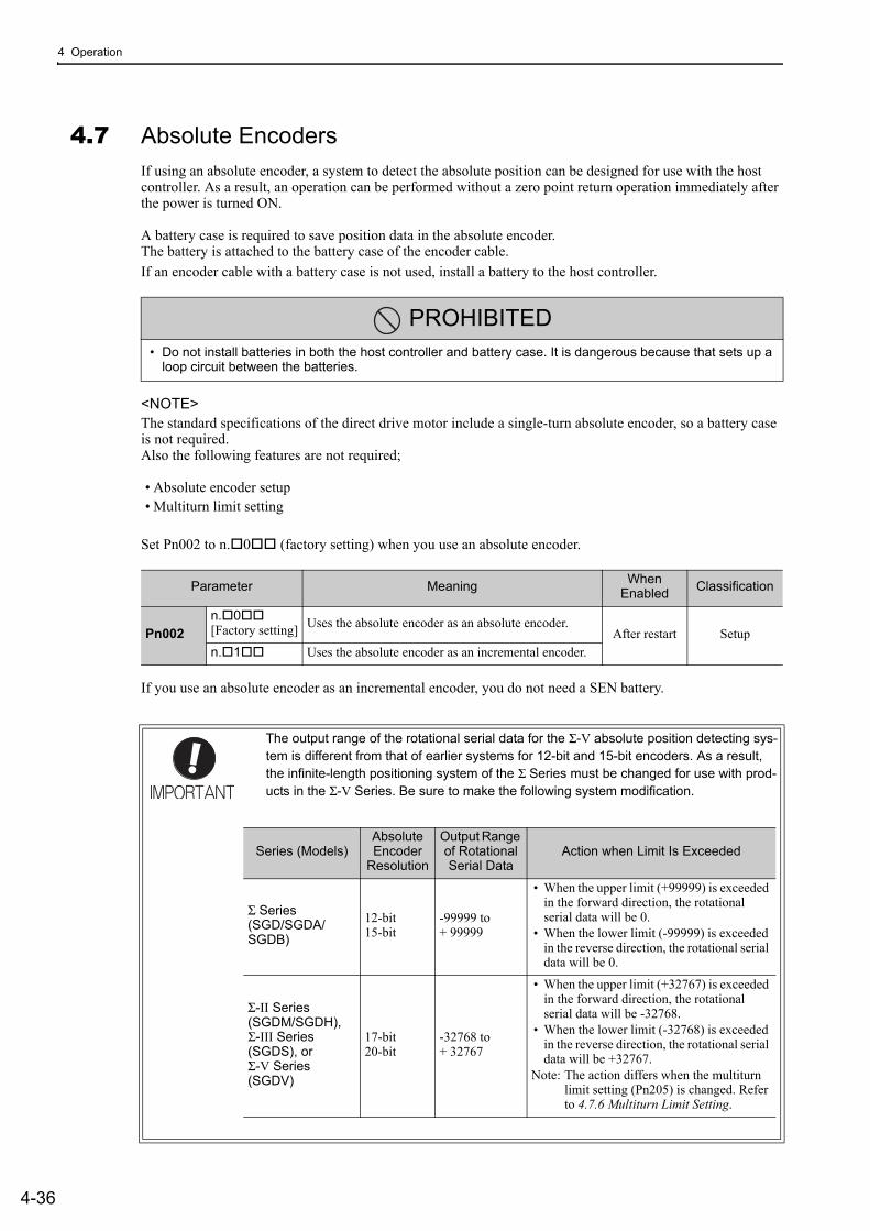
4 Operation
4-36
4.7 Absolute EncodersIf using an absolute encoder, a system to detect the absolute position can be designed for use with the host controller. As a result, an operation can be performed without a zero point return operation immediately after the power is turned ON.
A battery case is required to save position data in the absolute encoder.The battery is attached to the battery case of the encoder cable.
If an encoder cable with a battery case is not used, install a battery to the host controller.
<NOTE>The standard specifications of the direct drive motor include a single-turn absolute encoder, so a battery case is not required.Also the following features are not required;
• Absolute encoder setup• Multiturn limit setting
Set Pn002 to n.0 (factory setting) when you use an absolute encoder.
If you use an absolute encoder as an incremental encoder, you do not need a SEN battery.
PROHIBITED• Do not install batteries in both the host controller and battery case. It is dangerous because that sets up a
loop circuit between the batteries.
Parameter MeaningWhen
Enabled Classification
Pn002n.0[Factory setting]
Uses the absolute encoder as an absolute encoder.After restart Setup
n.1 Uses the absolute encoder as an incremental encoder.
The output range of the rotational serial data for the Σ-V absolute position detecting sys-tem is different from that of earlier systems for 12-bit and 15-bit encoders. As a result, the infinite-length positioning system of the Σ Series must be changed for use with prod-ucts in the Σ-V Series. Be sure to make the following system modification.
Series (Models)Absolute Encoder
Resolution
Output Range of Rotational Serial Data
Action when Limit Is Exceeded
Σ Series (SGD/SGDA/SGDB)
12-bit15-bit
-99999 to + 99999
• When the upper limit (+99999) is exceeded in the forward direction, the rotational serial data will be 0.
• When the lower limit (-99999) is exceeded in the reverse direction, the rotational serial data will be 0.
Σ-II Series (SGDM/SGDH), Σ-III Series (SGDS), or Σ-V Series (SGDV)
17-bit20-bit
-32768 to + 32767
• When the upper limit (+32767) is exceeded in the forward direction, the rotational serial data will be -32768.
• When the lower limit (-32768) is exceeded in the reverse direction, the rotational serial data will be +32767.
Note: The action differs when the multiturn limit setting (Pn205) is changed. Refer to 4.7.6 Multiturn Limit Setting.

4.7 Absolute Encoders
4-37
4
Ope
ratio
n
4.7.1 Connecting the Absolute EncoderThe following diagram shows the connection between a servomotor with an absolute encoder, the SERVO-PACK, and the host controller.
(1) Using an Encoder Cable with a Battery Case
∗1. The absolute encoder pin numbers for the connector wiring depend on the servomotors.
∗2. : represents shielded twisted-pair wires.
∗3. If you use an absolute encoder, provide power by installing an encoder cable with a battery case (model: JUSP-BA01-E) or install a battery on the host controller.
/PCO
ENC
34
CN2
171819202122
CN1
SG16
PAO/PAOPBO
/PBOPCO
Absolute encoder
(Shell) Battery*3
SERVOPACK
Phase A
Phase B
Phase C
Connector shell
Connector shell
*2
*2*1
0 V
Host controller
56
12
PG5VPG0V
PS/PS
BAT(+)BAT(-)
Phase A
Phase B
Phase C
R
R
R
Applicable line receiver: SN75ALS175 or MC3486 manufactured by Texas Instruments or the equivalentTerminating resistance R: 220 to 470 Ω
Encoder cable with battery case
SN75ALS174 output line driver manufactured by Texas Instruments or the equivalent
+ -

4 Operation
4.7.1 Connecting the Absolute Encoder
4-38
(2) Installing the Battery in the Host Controller
∗1. The absolute encoder pin numbers for the connector wiring depend on the servomotors.
∗2. : represents shielded twisted-pair wires.
∗3. If you use an absolute encoder, provide power by installing an encoder cable with a battery case (model: JUSP-BA01-E) or install a battery on the host controller.
• When Installing a Battery on the Encoder CableUse the encoder cable with a battery case that is specified by Yaskawa.For details, refer to the Σ-V Series Product Catalog (Catalog No.: KAEP S800000 42).
• When Installing a Battery on the Host ControllerInsert a diode near the battery to prevent reverse current flow.
/PCO
ENC
3 4
1415
BAT BAT
(+) (-)
CN2
171819202122
CN1
SG16
PAO/PAOPBO
/PBOPCO
Absolute encoder
(Shell)
SERVOPACK
Phase A
Phase B
Phase C
Connector shell
Connector shell
CN1
*2
*3
*2*1
0 V
Host controller
Battery
56
12
PG5VPG0V
PS/PS
BAT(+) BAT(-)
Phase A
Phase B
Phase C
R
R
R
Applicable line receiver: SN75ALS175 or MC3486 manufactured by Texas Instruments or the equivalentTerminating resistance R: 220 to 470 Ω
SN75ALS174 output line driver manufactured by Texas Instruments or the equivalent
+-
Circuit Example
+- Battery

4.7 Absolute Encoders
4-39
4
Ope
ratio
n
4.7.2 Absolute Data Request (SENS ON Command)The Turn Encoder Power Supply ON command (SENS_ON) must be sent to obtain absolute data as an output from the SERVOPACK.
The SENS_ON command is sent at the following timing.
∗ Send the SENS_OFF command to turn OFF the control power supply.
SERVOPACK control power supply 5 seconds max.
ON
OFF
OFF
ON (Normal status)
OFF
ON
50 ms
Rotational serial data
(Phase A)
(Phase B) (Phase B)
Approx. 15 ms 400 ms max.
1 to 3 ms
60 ms max. (90 ms typ.)
The servomotor will not be turned ON even if the SV_ON command is received during this interval.
ALM signal OFF (Alarm status)
SENS_ON(Turn Encoder Power Supply ON)
PAO
PBO
Servomotor power
Undefined
Undefined
(Phase A)
OFF
OFF
OFF
OFF
*
ON
Incremental pulses
Incremental pulses
Initial incremental pulses
Initial incremental pulses
OFF

4 Operation
4.7.3 Battery Replacement
4-40
4.7.3 Battery ReplacementIf the battery voltage drops to approximately 2.7 V or less, an absolute encoder battery error alarm (A.830) or an absolute encoder battery error warning (A.930) will be displayed.
If this alarm or warning is displayed, replace the batteries using the following procedure.
Use Pn008.0 to set either an alarm (A.830) or a warning (A.930).
• If Pn008.0 is set to 0, alarm detection will be enabled for 4 seconds after the ALM signal outputs max. 5 sec-onds when the control power is turned ON. No battery-related alarm will be displayed even if the battery voltage drops below the specified value after these 4 seconds.
• If Pn008.0 is set to 1, alarm detection will be always enabled after the ALM signal outputs max. 5 seconds when the control power supply is turned ON.
(1) Battery Replacement Procedure
Using an Encoder Cable with a Battery Case
1. Turn ON the control power supply of the SERVOPACK only.
2. Open the battery case cover.
Parameter Meaning When Enabled
Classification
Pn008
n.0 [Factory setting]
Outputs the alarm A.830 when the battery voltage drops.
After restart Setup
n.1Outputs the warning A.930 when the battery voltage drops.
4 s5 s max.
Warning A.930(Pn008.0 = 1)
Alarm A.830(Pn008.0 = 0)
ALM
OFF
Alarm status Normal status
ON
Batteryvoltage being
monitored
Battery voltagebeing monitored
Controlpower
Open the cover.

4.7 Absolute Encoders
4-41
4
Ope
ratio
n
3. Remove the old battery and install the new battery (model: JZSP-BA01).
4. Close the battery case cover.
5. After replacing the battery, turn OFF the control power supply to clear the absolute encoder battery error alarm (A.830).
6. Turn ON the control power supply again.
7. Check that the alarm display has been cleared and that the SERVOPACK operates normally.
Installing a Battery in the Host Controller
1. Turn ON the control power supply of the SERVOPACK only.
2. Remove the old battery and mount the new battery.
3. After replacing the battery, turn OFF the control power supply to clear the absolute encoder battery error alarm (A.830).
4. Turn ON the control power supply again.
5. Check that the alarm display has been cleared and that the SERVOPACK operates normally.
If the control power supply to the SERVOPACK is turned OFF and the battery is discon-nected (which includes disconnecting the encoder cable), the absolute encoder data will be deleted.
Install the battery (model: JZSP-BA01).
To the SERVOPACK
Encoder Cable
Close the cover.

4 Operation
4.7.4 Absolute Encoder Setup and Reinitialization
4-42
4.7.4 Absolute Encoder Setup and Reinitialization
Setting up and reinitialization of the absolute encoder are necessary in the following cases.
• When starting the machine for the first time• When an encoder backup error alarm (A.810) is generated • When an encoder checksum error alarm (A.820) is generated• When initializing the rotational serial data of the absolute encoder
Set up the absolute encoder with Fn008.
<NOTE>The standard specifications of the direct drive motor include a single-turn absolute encoder, so an encoder backup error alarm (A.810) will not occur for direct drive motors. Also, rotational serial data is always 0, so setting up the absolute encoder is not required.
(1) Precautions on Setup and Reinitialization
• The write prohibited setting (Fn010) must be set to Write permitted (P.0000).• Set up or reinitialize the encoder when the servomotor power is OFF.• If the following absolute encoder alarms are displayed, cancel the alarm by using the same method as the set
up (initializing) with Fn008. They cannot be canceled with the SERVOPACK Clear Warning or Alarm com-mand (ALM_CLR).• Encoder backup error alarm (A.810)• Encoder checksum error alarm (A.820)
• Any other alarms (A.8) that monitor the inside of the encoder should be canceled by turning OFF the power.
(2) Procedure for Setup and Reinitialization
Follow the steps below to setup or reinitialize the absolute encoder.
<NOTE>This setting can also be performed using the adjustment command (ADJ). For details on the Adjustment (ADJ) command, refer to the Σ-V Series/DC Power Input Σ-V Series/Σ-V Series for Large-Capacity Models User’s Manual MECHATROLINK-II Commands (Manual No.: SIEP S800000 54).
CAUTION• The rotational serial data will be a value between -2 and +2 rotations when the absolute encoder setup is
executed. The reference position of the machine system will change. Set the reference position of the host controller to the position after setup.If the machine is started without adjusting the position of the host controller, unexpected operation may cause injury or damage to the machine. Take sufficient care when operating the machine.
Step Panel Display Keys Description
1 Press the Key to select the utility function. And press the or Key to select the Fn008.
2 Press the Key to view the execution display of Fn008.
3 Keep pressing the Key until "PGCL1" is changed to "PGCL5."
B BF n 0 0 6 : A l m H i s t C l rF n 0 0 8 : M t u r n C l rF n 0 0 9 : R e f A d jF n 0 0 A : V e l A d j
- F U N C T I O N -
B B
M u l t i t u r n C l e a r
P G C L 1
B B
M u l t i t u r n C l e a r
P G C L 5

4.7 Absolute Encoders
4-43
4
Ope
ratio
n
4.7.5 Absolute Data Reception SequenceThe sequence in which the SERVOPACK receives outputs from the absolute encoder and transmits them to host controller is shown below.
(1) Outline of Absolute Data
The serial data, pulses, etc., of the absolute encoder that are output from the SERVOPACK are output from the PAO, PBO, and PCO signals as shown below.
Phase-C Output Specifications
The pulse width of phase C (origin pulse) changes depending on the encoder output pulse (Pn212), becoming the same width as phase A.
The output timing is one of the following.
• Synchronized with the rising edge of phase A• Synchronized with the falling edge of phase A• Synchronized with the rising edge of phase B• Synchronized with the falling edge of phase B
Note: When host controller receives the data of absolute encoder, do not perform counter reset using the output of PCO signal.
4Press the Key to setup the absolute encoder. After completing the setup, "DONE" is flashed for approximately one second and "BB" is displayed.
5 Press the Key to return to the display of the pro-cedure 1.
6 To enable the change in the setting, turn the power OFF and ON again.
(cont’d)
Step Panel Display Keys Description
B B
M u l t i t u r n C l e a r
P G C L 5
B BF n 0 0 6 : A l m H i s t C l rF n 0 0 8 : M t u r n C l rF n 0 0 9 : R e f A d jF n 0 0 A : V e l A d j
- F U N C T I O N -
Signal Name Status Contents
PAOAt initialization
Rotational serial dataInitial incremental pulses
Normal Operations Incremental pulses
PBOAt initialization Initial incremental pulses
Normal Operations Incremental pulses
PCO Always Origin pulses
ENC
CN1
PAO
PBO
PCO
CN2
Serialdata
Serial data→pulse conversion
HostcontrollerSERVOPACK
Dividingcircuit
(Pn212)

4 Operation
4.7.5 Absolute Data Reception Sequence
4-44
(2) Absolute Data Reception Sequence
1. Send the Turn Encoder Power Supply ON (SENS_ON) command from the host controller.
2. After 100 ms, the system is set to rotational serial data reception standby and the incremental pulse up/down counter is cleared to zero.
3. Eight characters of rotational serial data is received.
4. The system enters a normal incremental operation state about 400 ms after the last rotational serial data is received.
<NOTE>The output pulses are phase-B advanced if the servomotor is turning forward regardless of the setting in Pn000.0.
Rotational serial data: Indicates how many turns the motor shaft has made from the reference position, which was the position at setup.
Initial incremental pulses: Initial incremental pulses which provide absolute data are the number of pulses required to rotate the motor shaft from the servomotor origin to the present position.Just as with normal incremental pulses, these pulses are divided by the dividing circuit inside the SERVO-PACK and then output.
The initial incremental pulse speed depends on the setting of the encoder output pulses (Pn212). Use the fol-lowing formula to obtain the initial incremental pulse speed.
Setting of the Encoder Output Pulses (Pn212) Formula of the Initial Incremental Pulse Speed
16 to 16384
16386 to 32768
32772 to 65536
65544 to 131072
131088 to 262144
PAO
PBO
SENS_ON (Turn Encoder Power Supply ON)
Incremental pulses
Incremental pulses Undefined
Undefined (Phase A) (Phase A)
(Phase B) (Phase B)
Rotational serial data
400 ms max. 50 ms
1 to 3 ms
Approx. 15 ms
90 ms typ. 60 ms min.
Initial incremental pulses
Initial incremental pulses
680 × Pn212
16384 [kpps]
680 × Pn212
32768 [kpps]
680 × Pn212
65536 [kpps]
680 × Pn212
131072 [kpps]
680 × Pn212
262144 [kpps]

4.7 Absolute Encoders
4-45
4
Ope
ratio
n
Final absolute data PM is calculated by following formula.
PE=M× R+PO
PS=MS× R+PS’
PM=PE-PS
Note: The following formula applies in reverse mode. (Pn000.0 = 1)PE = -M × R + POPS = MS × R + PS'PM = PE - PS
CoordinatevalueValue of M
Reference position (at setup) Current position
-1 0 +1 +2 +3
+2+1-1 ±0
PEPMPS
POM × R
Signal Meaning
PE Current value read by encoder
M Rotational serial data
PO Number of initial incremental pulses
PS Absolute data read at setup (This is saved and controlled by the host controller.)
MS Rotational serial data read at setup
PS’ Number of initial incremental pulses read at setup
PM Current value required for the user’s system
R Number of pulses per encoder revolution (pulse count after dividing, value of Pn212)

4 Operation
4.7.5 Absolute Data Reception Sequence
4-46
(3) Rotational Serial Data Specifications and Initial Incremental Pulses
Rotational Serial Data Specifications
The rotational serial data is output from PAO signal.
Initial Incremental Pulses
The initial incremental pulses are output after division inside the SERVOPACK in the same way as for normal incremental pulses. Refer to 4.4.4 Encoder Output Pulses for details.
Data Transfer Method
Start-stop Synchronization (ASYNC)
Baud rate 9600 bps
Start bits 1 bit
Stop bits 1 bit
Parity Even
Character code ASCII 7-bit code
Data format 8 characters, as shown below.
Note 1. Data is "P+00000" (CR) or "P-00000" (CR) when the number of revolutions is zero.2. The revolution range is "-32768" to "+32767". When this range is exceeded, the data
changes from "+32767" to "-32678" or from "-32678" to "+32767". When changing multiturn limit, the range changes. For details, refer to 4.7.6 Multiturn Limit Setting.
DataStart bit Even parity
Rotational serial data, 5 digits
"+" or " - ""0" to "9"
"CR""P"
Stop bit
0 0 0 0 0 1 0 1 0 1

4.7 Absolute Encoders
4-47
4
Ope
ratio
n
(4) Transferring Alarm Contents
If an absolute encoder is used, the contents of alarms detected by the SERVOPACK are transmitted in serial data to the host controller from the PAO output when the Turn Encoder Power Supply OFF command (SENS_OFF) is received.
Note: The SENS_OFF command cannot be received while the servomotor power is ON.
Output example of alarm contents are as shown below.
Encoder power supply OFF
Error detectionEncoder power supply ON
Incremental pulse Serial DataEnlarged view
Turn Encoder Power Supply OFF(SENS_OFF)
Panel Display
PAO Output Serial Data Format
Upper 2 digits
A L M 5 1 . CR" " " " " " " " " " " " " "
or
Overspeed

4 Operation
4.7.6 Multiturn Limit Setting
4-48
4.7.6 Multiturn Limit SettingThe multiturn limit setting is used in position control applications for a turntable or other rotating device. For example, consider a machine that moves the turntable in the following diagram in only one direction.
Because the turntable moves in only one direction, the upper limit for revolutions that can be counted by an absolute encoder will eventually be exceeded. The multiturn limit (rotational serial data limit) is used in cases like this to prevent fractions from being produced by the integral ratio of the motor revolutions and turntable revolutions.
For a machine with a gear ratio of n:m, as shown above, the value of m minus 1 will be the setting for the mul-titurn limit setting (Pn205).
Multiturn limit setting (Pn205) = m-1
The case in which the relationship between the turntable revolutions and motor revolutions is m = 100 and n = 3 is shown in the following graph.
Pn205 is set to 99.
Pn205 = 100 − 1 = 99
Note: This parameter is valid when the absolute encoder is used.
The range of the data will vary when this parameter is set to anything other than the factory setting.
1. When the motor rotates in the reverse direction with the rotational serial data at 0, the rotational serial data will change to the setting in Pn205.
2. When the motor rotates in the forward direction with the rotational serial data at the Pn205 setting, the rota-tional serial data will change to 0.Set Pn205 to the following value: Desired rotation serial data -1.
When the set value in Pn205 is changed, a multiturn limit disagreement alarm (A.CC0) will be displayed because the multiturn limit value in the encoder will be different. For the procedure to change the multiturn
Pn205Multiturn Limit Setting
ClassificationSetting Range Setting Unit Factory Setting When Enabled
0 to 65535 1 Rev 65535 After restart Setup
Turntable
Gear
Servomotor
0 1 2 3 4 5 6 7 8 9
Motor rotations
100 200 300 0
100
50
Rotational serial data
Turntable rotations
Set value of Pn205 = 99 Turntable rotations
Rotational serial data
Speed Position Torque

4.7 Absolute Encoders
4-49
4
Ope
ratio
n
limit value in the encoder, refer to 4.7.7 Multiturn Limit Disagreement Alarm (A.CC0).
<NOTE>The standard specifications of the direct drive motor include a single-turn absolute encoder. Therefore, the encoder’s rotational serial data is always 0.The absolute value of the load side can be created with the motor shaft angle only even when constructing an absolute position detecting system because the servomotor and the load can be directly connected.
4.7.7 Multiturn Limit Disagreement Alarm (A.CC0)When the multiturn limit set value is changed with parameter Pn205, a multiturn limit disagreement alarm (A.CC0) will be displayed because the value differs from that of the encoder.
If this alarm is displayed, perform the operation described below and change the multiturn limit value in theencoder to the value set in Pn205.
<NOTE>This setting can also be performed with the adjustment command (ADJ). For details on the ADJ (Adjustment) command, refer to the Σ-V Series/DC Power Input Σ-V Series/Σ-V Series for Large-Capacity Models User’s Manual MECHATROLINK-II Commands (Manual No.: SIEP S800000 54).
Factory Setting (= 65535) Other Setting (≠65535)
+32767
-32768 Motor rotations
0 Rotational serial data
Reverse Forward
0 Motor rotations
Pn205 setting value ReverseForward
Rotational serial data
Alarm Display Alarm Name Alarm Output Meaning
A.CC0 Multiturn Limit Disagreement OFF (H) Different multiturn limits have been set in the encoder and SERVOPACK.
Step Display after Operation Keys Operation
1 Press the Key to select the utility function. And press the or Key to select the Fn013.
2
Press the Key to view the execution display of Fn013.Note: If the display is not switched and “NO-OP” is
displayed in the status display, the Write Pro-hibited Setting (Fn010 = 0001) is set. Check the setting and reset.
3
Press the Key to set the multiturn limit value. When the setting is completed, the status display shows "DONE" for one second. The status display then returns to show "A.CC0" again.
Note: If the Key is pressed instead of the Key, the multiturn limit value will not be reset.
4 Press the Key to return to the display the proce-dure 1.
5 To enable the change in the setting, turn the power OFF and ON again.
A . C C 0F n 0 1 2 : S o f t V e rF n 0 1 3 : M t u r n L m S e tF n 0 1 4 : O p t I n i tF n 0 1 B : V i b l v l I n i t
- F U N C T I O N -
A . C C 0M u l t i t u r n L i m i t
S e tS t a r t : [ D A T A ]R e t u r n : [ S E T ]
A . C C 0 M u l t i t u r n L i m i t S e t S t a r t : [ D A T A ] R e t u r n : [ S E T ]
A . C C 0F n 0 1 2 : S o f t V e rF n 0 1 3 : M t u r n L m S e tF n 0 1 4 : O p t I n i tF n 0 1 B : V i b l v l I n i t
- F U N C T I O N -

4 Operation
4.7.8 Absolute Encoder Origin Offset
4-50
4.7.8 Absolute Encoder Origin Offset
If using the absolute encoder, the positions of the encoder and the offset of the machine coordinate system (APOS) can be set. Use Pn808 to make the setting. After the SENS_ON command is received by MECHA-TROLINK communications, this parameter will be enabled.
<Example>If the encoder position (X) is set at the origin of the machine coordinate system (0), Pn808 = X.
Pn808
Absolute Encoder Origin Offset ClassificationSetting Range Setting Unit Factory Setting When Enabled
-1073741823 to 1073741823
1 reference unit 0 Immediately Setup
Position
Encoder position: Origin
Origin
Machine coordinatesystem position(APOS)
Encoder position
Encoder positionPn808

4.8 Other Output Signals
4-51
4
Ope
ratio
n
4.8 Other Output SignalsThis section explains other output signals.
Use these signals according to the application needs, e.g., for machine protection.
4.8.1 Servo Alarm Output Signal (ALM)This section describes signals that are output when the SERVOPACK detects errors and resetting methods.
(1) Servo Alarm Output Signal (ALM)
This signal is output when the SERVOPACK detects an error.
(2) Alarm Reset Method
If a servo alarm (ALM) occurs, use one of the following methods to reset the alarm after eliminating the cause of the alarm.
Resetting Alarms by Sending Clear Warning or Alarm Command (ALM_CLR)
For details, refer to the Σ-V Series/DC Power Input Σ-V Series/Σ-V Series for Large-Capacity Models User’s Manual MECHATROLINK-II Commands (Manual No.: SIEP S800000 54).
Resetting Alarms Using the Digital Operator
Press the ALARM RESET Key on the digital operator. For details, refer to Σ-V Series User’s Manual, Opera-tion of Digital Operator (No.: SIEP S800000 55).
4.8.2 Warning Output Signal (/WARN)This signal is for a warning issued before the occurrence of an alarm.Refer to 9.2.1 List of Warnings.
Signal Specifications
Note: Use parameter Pn50F.3 to allocate the /WARN signal for use. For details, refer to 3.3.2 Output Signal Alloca-tions.
Configure an external circuit so that this alarm output turns OFF the main circuit power supply for the SERVOPACK whenever an error occurs.
Type Signal Name
ConnectorPin Number
Setting Meaning
Output ALM CN1-3, 4ON (closed) Normal SERVOPACK status
OFF (open) SERVOPACK alarm status
Be sure to eliminate the cause of the alarm before resetting it.
If the alarm is reset and operation continued without eliminating the cause of the alarm, it may result in damage to the equipment or fire.
Type Signal Name
Connector Pin Number Setting Meaning
Output /WARN Must be allocatedON (closed) Warning status
OFF (open) Normal status

4 Operation
4.8.3 Rotation Detection Output Signal (/TGON)
4-52
4.8.3 Rotation Detection Output Signal (/TGON)This output signal indicates that the servomotor is rotating at the speed set for Pn502 or a higher speed.
(1) Signal Specifications
Note: Use parameter Pn50E.2 to allocate the /TGON signal for use. For details, refer to 3.3.2 Output Signal Alloca-tions.
(2) Related Parameter
Set the range in which the /TGON signal is output using the following parameter.
4.8.4 Servo Ready Output Signal (/S-RDY)This signal is turned ON when the SERVOPACK is ready to accept the servo ON (SV_ON) command.
The /S-RDY signal is turned ON under the following conditions.
• The main circuit power supply is ON.• No hard wire base block state• No servo alarms• The Turn Encoder Power Supply ON (SENS_ON) command is received. (When an absolute encoder is
used.)<NOTE>• If an absolute encoder is used, the output of absolute data to the host controller must have been completed
when the SENS_ON command is received.• For details on the hard wire base block function, refer to 4.9.1 Hard Wire Base Block (HWBB) Function.
Signal Specifications
Note 1. Use parameter Pn50E.3 to allocate the /S-RDY signal for use. For details, refer to 3.3.2 Output Signal Alloca-tions.
2. For details on the hard wire base block function and the servo ready output signal, refer to 4.9.1 Hard Wire Base Block (HWBB) Function.
TypeSignal Name
Connector Pin Number Setting Meaning
Output /TGON Must be allocated
ON (closed) Servomotor is rotating with the motor speed above the setting in Pn502.
OFF (open) Servomotor is rotating with the motor speed below the setting in Pn502.
Pn502
Rotation Detection Level Classification
Setting Range Setting Unit Factory Setting When Enabled
1 to 10000 1 min-1 20 Immediately Setup
Speed Position Torque
TypeSignal Name
Connector Pin Number Setting Meaning
Output /S-RDY Must be allocated
ON (closed) The SERVOPACK is ready to accept the SV_ON command.
OFF (open) The SERVOPACK is not ready to accept the SV_ON command.

4.8 Other Output Signals
4-53
4
Ope
ratio
n
4.8.5 Speed Coincidence Output Signal (/V-CMP)The speed coincidence output signal (/V-CMP) is output when the actual servomotor speed is the same as the reference speed. The host controller uses the signal as an interlock. This signal is the output signal during speed control.
Note: Use parameter Pn50E.1 to allocate the /V-CMP signal for use. Refer to 3.3.2 Output Signal Allocations for details.
The /V-CMP signal is output when the difference between the reference speed and actual motor speed is below this setting.
<Example>
The /V-CMP signal is output at 1900 to 2100 min-1 if the Pn503 is set to 100 and the reference speed is 2000 min-1.
Type Signal Name
Connector Pin Number Setting Meaning
Output /V-CMP Must be allocatedON (closed) Speed coincides.
OFF (open) Speed does not coincide.
Pn503
Speed Coincidence Signal Output WidthClassification
Setting Range Setting Unit Factory Setting When Enabled
0 to 100 1 min-1 10 Immediately Setup
Speed
Motor speed
Reference speed
/V-CMP is output in
this range.
Pn503

4 Operation
4.8.6 Positioning Completed Output Signal (/COIN)
4-54
4.8.6 Positioning Completed Output Signal (/COIN)This signal indicates that servomotor movement has been completed during position control.
When the difference between the number of references output by the host controller and the travel distance of the servomotor (position error) drops below the set value in the parameter, the positioning completion signal will be output.
Use this signal to check the completion of positioning from the host controller.
Note: Use parameter Pn50E.0 to allocate the /COIN signal for use. Refer to 3.3.2 Output Signal Allocations for details.
The positioning completed width setting has no effect on final positioning accuracy.
Note: If the parameter is set to a value that is too large, a positioning completed signal might be output if the position error is low during a low speed operation. This will cause the positioning completed signal to be output continuously. If this signal is output unexpectedly, reduce the set value until it is no longer output.
If the position error is kept to a minimum when the positioning completed width is small, use Pn207.3 to change output timing for the /COIN signal.
Type Signal Name
Connector Pin Number Setting Meaning
Output /COIN Must be allocatedON (closed) Positioning has been completed.
OFF (open) Positioning is not completed.
Pn522Positioning Completed Width
ClassificationSetting Range Setting Unit Factory Setting When Enabled
0 to 1073741824 1 reference unit 7 Immediately Setup
Position
Motor speed
ReferenceMotor speed
/COIN
Time
Time
Time
Position error
Effective at ON (close).
Pn522
Parameter Name Meaning When Enabled Classification
Pn207
n.0[Factory setting]
/COIN Output Timing
When the absolute value of the posi-tion error is below the positioning completed width (Pn522).
After restart Setupn.1
When the absolute value of the posi-tion error is below the positioning completed width (Pn522), and the ref-erence after applying the position ref-erence filter is 0.
n.2
When the absolute value of the posi-tion error is below the positioning completed width (Pn522), and the position reference input is 0.

4.8 Other Output Signals
4-55
4
Ope
ratio
n
4.8.7 Positioning Near Output Signal (/NEAR)Before confirming that the positioning completed signal has been received, the host controller first receives a positioning near signal and can prepare the operating sequence after positioning has been completed. The time required for this sequence after positioning can be shortened.
This signal is generally used in combination with the positioning completed output signal.
Note: Use parameter Pn510.0 to allocate the /NEAR signal for use. Refer to 3.3.2 Output Signal Allocations for details.
The positioning near signal (/NEAR) is output when the difference between the number of references output by the host controller and the travel distance of the servomotor (position error) is less than the set value.
Note: Normally, the value of Pn524 should be larger than that for the positioning completed width (Pn522).
TypeSignal Name
ConnectorPin Number Setting Meaning
Output /NEAR Must be allocated
ON (closed)The servomotor has reached a point near to positioning completed.
OFF (open) The servomotor has not reached a point near to positioning completed.
Pn524NEAR Signal Width
ClassificationSetting Range Setting Unit Factory Setting When Enabled
1 to 1073741824 1 reference unit 1073741824 Immediately Setup
Position
Motor speed Reference Motor speed
Time
Time
Time Effective at ON (close).
Effective at ON (close).Time
Position error
/NEAR
/COIN
Pn524 Pn522
0

4 Operation
4.8.8 Speed Limit Detection Signal (/VLT)
4-56
4.8.8 Speed Limit Detection Signal (/VLT)This function limits the speed of the servomotor to protect the machine.
A servomotor in torque control is controlled to output the specified torque, but the motor speed is not con-trolled. Therefore, if an excessive reference torque is set for the load torque on the machinery side, the speed of the servomotor may increase greatly. If that may occur, use this function to limit the speed.
Note: The actual limit value of motor speed depends on the load conditions of the servomotor.
The parameters related to the speed limit, such as for selecting the speed limit method, are described next.
(1) Signals Output during Servomotor Speed Limit
The following signal is output when the motor speed reaches the limit speed.
Note: Use parameter Pn50F.1 to allocate the /VLT signal for use. For details, refer to 3.3.2 Output Signal Allocations.
(2) Speed Limit Setting
Select the speed limit mode with Pn002.1.
With No Speed Limit With Speed Limit
Motor speed
Time
Maximum speed
Danger of damage due tocritical speed.
Motor speed
Limiting speed
Safe operation withspeed limit.
Time
TypeSignal Name
ConnectorPin Number Setting Meaning
Output /VLT Must be allocatedON (closed) Servomotor speed limit being applied.
OFF (open) Servomotor speed limit not being applied.
Parameter Meaning When Enabled
Classification
Pn002
n.0[Factory setting]
VLIM (the speed limit value during torque control) is not available. Uses the value set in Pn407 as the speed limit (internal speed limit function). After restart Setup
n.1VLIM operates as the speed limit value (external speed limit function).
4.8 Other Output Signals
4-57
4
Ope
ratio
n
Internal Speed Limit Function
If the internal speed limit function is selected in Pn002.1, set the limit of the maximum speed of the servomo-tor in Pn407. The limit of the speed in Pn408.1 can be either the maximum speed of the servomotor or the overspeed alarm detection speed. Select the overspeed alarm detection speed to limit the speed to the maxi-mum speed of the servomotor or the equivalent.
Note: The servomotor’s maximum speed or the overspeed alarm detection speed will be used when the setting in this parameter exceeds the maximum speed of the servomotor used.
External Speed Limit Function
If the external speed limit mode is selected in Pn002.1, the motor speed is controlled by the speed limit value (VLIM). For details, refer to the Σ-V Series/DC Power Input Σ-V Series/Σ-V Series for Large-Capacity Mod-els User’s Manual MECHATROLINK-II Commands (Manual No.: SIEP S800000 54).
Pn407
Speed Limit During Torque ControlClassification
Setting Range Setting Unit Factory Setting When Enabled
0 to 10000 1 min-1 10000 Immediately Setup
Torque
Parameter Meaning When Enabled
Classification
Pn408
n.0[Factory setting]
Uses the smaller value of the maximum motor speed and the value of Pn407 as the speed limit value.
After restart Setup
n.1 Uses the smaller value of the overspeed alarm detec-tion speed and the value of Pn407 as speed limit value.

4 Operation
4.9.1 Hard Wire Base Block (HWBB) Function
4-58
4.9 Safety FunctionThe safety function is incorporated in the SERVOPACK to reduce the risk associated with the machine by pro-tecting workers from injury and by securing safe machine operation. Especially when working in hazardous areas inside the safeguard, as for machine maintenance, it can be used to avoid adverse machine movement.
4.9.1 Hard Wire Base Block (HWBB) FunctionThe Hard Wire Base Block function (hereinafter referred to as HWBB function) is a safety function designed to baseblock the servomotor (shut off the motor current) by using the hardwired circuits. Each circuit for two channel input signals blocks the run signal to turn off the power module that controls the motor current, and the motor current is shut off.
The input signals are connected to the 0 V common. A connection example is provided in the following figure.
For the safety function signal connections, the input signal is the 0 V common and the output signal is the source output. This is opposite to other signals described in this man-ual. To avoid confusion, the ON and OFF status of signals for the safety functions are defined as follows:
ON: The state in which the relay contacts are closed or the transistor is ON and current flows into the signal line.
OFF: The state in which the relay contacts are open or the transistor is OFF and no cur-rent flows into the signal line.
CN8
/HWBB1+ 4
3
6
5
/HWBB1-
/HWBB2+
/HWBB2- 0 V
SERVOPACK
Switch
Block
Block
Power module
Power supply
24-V power supply
Fuse
Motor
Control circuit Run signal

4.9 Safety Function
4-59
4
Ope
ratio
n
(1) Risk Assessment
When using the HWBB function, be sure to perform a risk assessment of the servo system in advance. Make sure that the safety level of the standards is met. For details on the standards, refer to Harmonized Standards in the front of this manual.
Note: To meet the performance level d (PLd) in EN ISO 13849-1, the EDM signal must be monitored by a host controller. If the EDM signal is not monitored by a host controller, the system only qualifies for the performance level c (PLc).
The following risks can be estimated even if the HWBB function is used. These risks must be included in the risk assessment.
• The servomotor will move in an application where external force is applied to the servomotor (for example, gravity on the vertical axis). Take measures to secure the servomotor, such as installing a mechanical brake.
• The servomotor may move within the electric angle of 180 degrees in case of the power module failure, etc. Make sure that safety is ensured even in that situation. The rotation angle depends on the motor type. The maximum rotation angle is given below. Rotational motor: 1/6 rotation max. (rotation angle at the motor shaft) Direct drive motor:1/20 rotation max. (rotation angle at the motor shaft)
• The HWBB function does not shut off the power to the SERVOPACK or electrically isolate it. Take mea-sures to shut off the power to the SERVOPACK when performing maintenance on it.
(2) Hard Wire Base Block (HWBB) State
The SERVOPACK will be in the following state if the HWBB function operates. If the /HWBB1 or /HWBB2 signal is OFF, the HWBB function will operate and the SERVOPACK will enter a hard wire baseblock (HWBB) state.
/HWBB1/HWBB2
M-IIcommand
Status fieldSVON
Motioncommand, etc.
SV_OFFcommand
1 0
0 1
SMONcommand, etc.
IO monitor fieldHBB
SERVOPACKstate
ON(Normal operation)
(Normal operation)
OFF(Motor current shut-off request)
(Motor current shut-off request)
HWBB stateBB stateOperation
1 0
0 1
Motioncommand, etc.
SMONcommand, etc.
/HWBB1/HWBB2
M-IIcommand
Status fieldSVON
IO monitor fieldHBB
SERVOPACKstate
ON OFF
HWBB stateOperation
The HWBB function operates after the servomotor power is turned OFF.
The HWBB function operates while the servomotor power is ON.
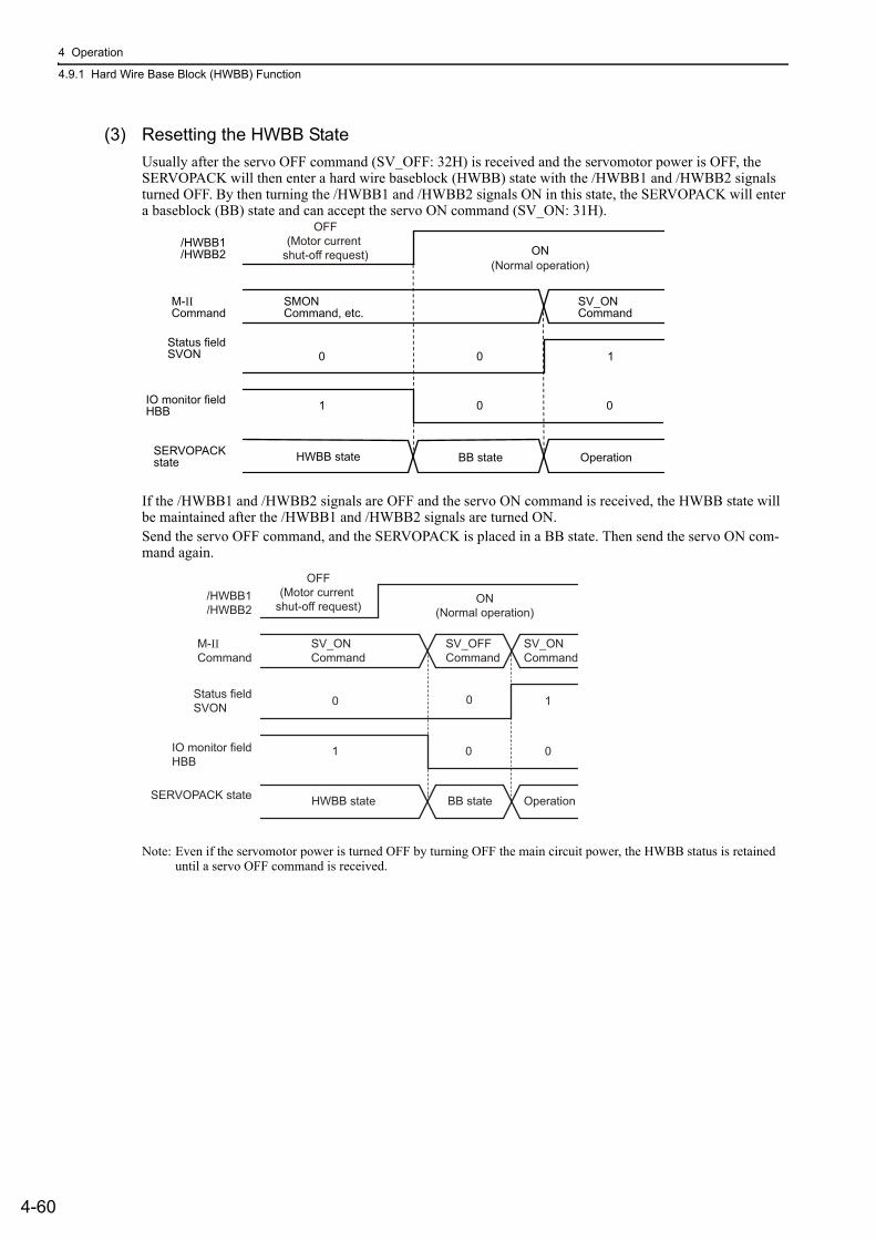
4 Operation
4.9.1 Hard Wire Base Block (HWBB) Function
4-60
(3) Resetting the HWBB State
Usually after the servo OFF command (SV_OFF: 32H) is received and the servomotor power is OFF, the SERVOPACK will then enter a hard wire baseblock (HWBB) state with the /HWBB1 and /HWBB2 signals turned OFF. By then turning the /HWBB1 and /HWBB2 signals ON in this state, the SERVOPACK will enter a baseblock (BB) state and can accept the servo ON command (SV_ON: 31H).
If the /HWBB1 and /HWBB2 signals are OFF and the servo ON command is received, the HWBB state will be maintained after the /HWBB1 and /HWBB2 signals are turned ON.Send the servo OFF command, and the SERVOPACK is placed in a BB state. Then send the servo ON com-mand again.
Note: Even if the servomotor power is turned OFF by turning OFF the main circuit power, the HWBB status is retained until a servo OFF command is received.
/HWBB1/HWBB2 ON
M-IICommand
Status fieldSVON 10 0
0 01
SMONCommand, etc.
SV_ONCommand
IO monitor fieldHBB
SERVOPACKstate HWBB state BB state Operation
(Normal operation)
OFF(Motor current
shut-off request)
/HWBB1/HWBB2
OFF(Motor current
shut-off request) ON(Normal operation)
Status fieldSVON
IO monitor fieldHBB
SERVOPACK state HWBB state BB state Operation
SV_ONCommand
SV_ONCommand
0
1 0
0
0
1
M-IICommand
SV_OFFCommand

4.9 Safety Function
4-61
4
Ope
ratio
n
(4) Related Commands
If the HWBB function is working with the /HWBB1 or /HWBB2 signal turned OFF, the setting of IO monitor-ing field D10 (HBB) changes to 1, so the status of the upper level apparatus can be known by looking at the setting of this bit.
If the status becomes HWBB status during the execution of the next command, a command warning is issued. If a warning is given, clear the alarm to return to normal operational status. After stopping or canceling the action command, using the sequence of commands to return to the HWBB status is recommended.
(5) Error Detection in HWBB Signal
If only the /HWBB1 or /HWBB2 signal is input, an A.Eb1 alarm (Safety Function Signal Input Timing Error) will occur unless the other signal is input within 10 seconds. This makes it possible to detect failures, such as
disconnection of the HWBB signals.
Object Action Commands
Servo ON (SV_ON)
Interpolating (INTERPORATE)
Positioning (POSING)
Constant speed feed (FEED)
Interpolating with position detection function (LATCH)
External input positioning (EX_POSING)
Homing (ZRET)
CAUTION• The safety function signal input timing error alarm (A.Eb1) is not a safety-related part of a control system. Keep this
in mind in the system design.

4 Operation
4.9.1 Hard Wire Base Block (HWBB) Function
4-62
(6) Connection Example and Specifications of Input Signals (HWBB Signals)
The input signals must be redundant. A connection example and specifications of input signals (HWBB sig-nals) are shown below.
Connection Example
Specifications
The input signals (HWBB signals) have the following electrical characteristics.
If the HWBB function is requested by turning OFF the /HWBB1 and /HWBB2 input signals on the two chan-nels, the power supply to the servomotor will be turned OFF within 20 ms (see below).
Note 1. The OFF status is not recognized if the total OFF time of the /HWBB1 and /HWBB2 signals is 0.5 ms or shorter.2. The status of the input signals can be checked using monitor displays. For details, refer to 7.5 Monitoring Safety
Input Signals.
For safety function signal connections, the input signal is the 0 V common and the output signal is the source output. This is opposite to other signals described in this manual. To avoid confusion, the ON and OFF status of signals for safety functions are defined as fol-lows:
ON: The state in which the relay contacts are closed or the transistor is ON and current flows into the signal line.
OFF: The state in which the relay contacts are open or the transistor is OFF and no cur-rent flows into the signal line.
TypeSignal Name
ConnectorPin Number Setting Meaning
Input
/HWBB1CN8-4CN8-3
ON (closed) Does not use the HWBB function. (normal operation)
OFF (open) Uses the HWBB function. (motor current shut-off request)
/HWBB2CN8-6CN8-5
ON (closed) Does not use the HWBB function. (normal operation)
OFF (open) Uses the HWBB function. (motor current shut-off request)
/HWBB1+ 4
3
6
5
/HWBB1-
/HWBB2+
/HWBB2- 0 V
CN8 24-V power
supply
Fuse
Switch
SERVOPACK
Use a switchthat has micro-currentcontacts.
Items Characteristics Remarks
Internal Impedance 3.3 kΩ −
Operation Movable Volt-age Range +11 to + 25 V −
Maximum Delay Time 20 ms Time from the /HWBB1 and /HWBB2 signals are OFF to the HWBB function operates.
/HWBB1 /HWBB2
Normal operation SERVOPACK State
HWBB state
ON(Normal operation)
OFF (Motor current shut-off request)
Within 20 ms

4.9 Safety Function
4-63
4
Ope
ratio
n
(7) Operation with Utility Functions
The HWBB function works while the SERVOPACK operates in the utility function.
If any of the following utility functions is being used with the /HWBB1 and /HWBB2 signals turned OFF, the SERVOPACK cannot be operated by turning ON the /HWBB1 and /HWBB2 signals. Cancel the utility func-tion first, and then set the SERVOPACK to the utility function again and restart operation.
• JOG operation (Fn002)• Origin search (Fn003) • Program JOG operation (Fn004)• Advanced autotuning (Fn201) • EasyFFT (Fn206)• Automatic offset-signal adjustment of motor current detection signal (Fn00E)
(8) Servo Ready Output (/S-RDY)
The servo ready output will turn OFF because the servo ON (SV_ON: 31 H) command cannot be accepted in the HWBB state.The servo ready output will turn ON if the servomotor power is OFF (set to BB state) when both the /HWBB1 and /HWBB2 signals are ON.
The following diagram shows an example where the main circuit power supply is turned ON, the Turn Encoder Power Supply ON (SENS_ON) command is sent (with an absolute encoder), and no servo alarm occurs.
(9) Brake Signal (/BK)
When the /HWBB1 or /HWBB2 signal is OFF and the HWBB function operates, the brake signal (/BK) will turn OFF. At that time, Pn506 (brake reference - servo OFF delay time) will be disabled. Therefore, the servo-motor may be moved by external force until the actual brake becomes effective after the brake signal (/BK)
turns OFF.
/HWBB1 /HWBB2
ServomotorPower
/S-RDY
ON (Normal
operation)
ON(Normal operation)
OFF ON
OFF(Motor current
shut-off request)
ON OFF
ON
HWBB state BB state Operating SERVOPACK State
CAUTION• The brake signal is not a safety-related part of a control system. Be sure to design the system so that the
system will not be put into danger if the brake signal fails in the HWBB state. Moreover, if a servomotor with a brake is used, keep in mind that the brake for the servomotor is used only to prevent the movable part from being moved by gravity or an external force and it cannot be used to brake the servomotor.

4 Operation
4.9.2 External Device Monitor (EDM1)
4-64
(10) Dynamic Brake
If the dynamic brake is enabled in Pn001.0 (Stopping Method for Servomotor after SV_OFF Command is Received), the servomotor will come to a stop under the control of the dynamic brake when the HWBB func-
tion works while the /HWBB1 or /HWBB2 signal is OFF.
(11) Servo Alarm Output Signal (ALM)
In the HWBB state, the servo alarm output signal (ALM) is not sent.
4.9.2 External Device Monitor (EDM1)The external device monitor (EDM1) functions to monitor failures in the HWBB function. Connect the moni-tor to feedback signals to the safety function device.
Note: To meet the performance level d (PLd) in EN ISO13849-1, the EDM signal must be monitored by a host controller. If the EDM signal is not monitored by a host controller, the system only qualifies for the performance level c (PLc).
Failure Detection Signal for EDM1 Signal
The relation of the EDM1, /HWBB1, and /HWBB2 signals is shown below.
Detection of failures in the EDM1 circuit can be checked using the following four status of the EDM1 signal in the table. Failures can be detected if the failure status can be confirmed, e.g., when the power supply is turned ON.
CAUTION• The dynamic brake is not a safety-related part of a control system. Be sure to design the system so that
the system will not be put into danger if the servomotor coasts to a stop in the HWBB state. Usually, use a sequence in which the HWBB state occurs after the servomotor is stopped using the reference.
• If the application frequently uses the HWBB function, do not use the dynamic brake to stop the servomo-tor. Otherwise element deterioration in the SERVOPACK may result. To prevent internal elements from deteriorating, use a sequence in which the HWBB state occurs after the servomotor has come to a stop.
Signal Name
Logic
/HWBB1 ON ON OFF OFF
/HWBB2 ON OFF ON OFF
EDM1 OFF OFF OFF ON
WARNING• The EDM1 signal is not a safety output. Use it only for monitoring a failure.

4.9 Safety Function
4-65
4
Ope
ratio
n
(1) Connection Example and Specifications of EDM1 Output Signal
Connection example and specifications of EDM1 output signal are explained below.
Connection Example
EDM1 output signal is used for source circuit.
Specifications
Electrical characteristics of EDM1 signal are as follows.
For safety function signal connections, the input signal is the 0 V common and the output signal is the source output. This is opposite to other signals described in this manual. To avoid confusion, the ON and OFF status of signals for safety functions are defined as fol-lows:
ON: The state in which the relay contacts are closed or the transistor is ON and current flows into the signal line.
OFF: The state in which the relay contacts are open or the transistor is OFF and no cur-rent flows into the signal line.
External device
EDM1+ CN8
EDM1-
8
7
0 V
24-V power supply
SERVOPACK
Type SignalName
ConnectorPin Number Setting Meaning
Output EDM1CN8-8CN8-7
ON (closed) Both the /HWBB1 and the /HWBB2 signals are working normally.
OFF (open)The /HWBB1 signal, the /HWBB2 signal or both are not working normally.
Items Characteristics Remarks
Maximum Allowable Voltage 30 VDC −
Maximum Allowable Current 50 mADC −
Maximum Voltage Drop at ON 1.0 V Voltage between EDM1+ and EDM1- when current is 50 mA
Maximum Delay Time 20 ms Time from the change in /HWBB1 or /HWBB2 until the change in EDM1

4 Operation
4.9.3 Application Example of Safety Functions
4-66
4.9.3 Application Example of Safety FunctionsAn example of using safety functions is shown below.
(1) Connection Example
In the following example, a safety unit is used and the HWBB function operates when the guard opens.
When a guard opens, both of signals, the /HWBB1 and the /HWBB2, turn OFF, and the EDM1 signal turns ON. Since the feedback is ON when the guard closes, the safety unit is reset, and the /HWBB1 and the /HWBB2 signals turn ON, and the operation becomes possible.
Note: The EDM1 signal is used as a sourcing output. Connect the EDM1 so that the current flows from EMD1+ to EMD1-.
(2) Failure Detection Method
In case of a failure such as the /HWBB1 or the /HWBB2 signal remains ON, the safety unit is not reset when the guard closes because the EDM1 signal keeps OFF. Therefore starting is impossible, then the failure is detected.
In this case, an error in the external device, disconnection or short-circuiting of the external wiring, or a failure in the SERVOPACK must be considered. Find the cause and correct the problem.
/HWBB1+ 4
3
6
5
8
7
A1
A2
T11 T12 T21
T31 T32 T33 S24 S14
T22
/HWBB1-
/HWBB2+
/HWBB2-
EDM1+
EDM1-
0 V
CN8
SERVOPACK Output
24-V powersupply
Guard Safety unit G9SX-BC202
manufactured by OMRON Corp.
Fuse
Close Limit switch
Power supply input
Input Reset/feedback input
Open

4.9 Safety Function
4-67
4
Ope
ratio
n
(3) Procedure
4.9.4 Confirming Safety FunctionsWhen starting the equipment or replacing the SERVOPACK for maintenance, be sure to conduct the following confirmation test on the HWBB function after wiring.
• Confirm that the SERVOPACK enters a hard wire base block state and that the servomotor does not operate when the /HWBB1 and /HWBB2 signals are OFF.
• Check the ON/OFF states of the /HWBB1 and /HWBB2 signals with Un015.→ If the ON/OFF states of the signals do not coincide with the display, an error in the external device, dis-connection or short-circuiting of the external wiring, or a failure in the SERVOPACK must be considered. Find the cause and correct the problem.
• Check with the display of the feedback circuit input of the connected device to confirm that the EDM1 sig-nal is OFF while in normal operation.
1
2
3
4
6
Request to open the guard.
Open the guard and enter.
The /HWBB1 and /HWBB2 signals are OFF and HWBB function operates. (The operation in the guard is available.)
5 After completing the operation, leave and close the guard.
When the servomotor is operating, the host controller stops the servomotor and sends the servo OFF command (SV_OFF).
The host controller sends the servo ON com-mand (SV_ON).

4 Operation
4.9.5 Safety Device Connections
4-68
4.9.5 Safety Device ConnectionsThere are two types of the safety function’s jumper connectors that are attached to SERVOPACKs. You must remove a safety function’s jumper connector before connecting a safety function device. The connection method depends on the connector type that is used. Read the following procedures well before you attach a safety function device.
Use the following procedures to attach safety function devices.
(1) Connector Type A
1. SGDV-R70F, SGDV-R90F, SGDV-2R1F, SGDV-R70A, SGDV-R90A, SGDV-1R6A, SGDV-2R8A, SGDV-1R9D, SGDV-3R5D, or SGDV-5R4D SERVOPACKDisconnect the servomotor terminal connector while pressing in the servomotor terminal connector lock.
When Using Any Other SERVOPACKIt is not necessary to remove the servomotor connection terminals. Proceed to step 2.
2. Slide the lock injector on the safety function's jumper connector toward the SERVOPACK to unlock it and remove the safety function's jumper connector.
Note: The safety function's jumper connector may be damaged if removed while the lock is still on.
Connector Type A Connector Type B
Enlarged View
1. Press in the lock.
2. Remove the servomotor terminal connector while pressing in the lock.
Servomotor terminal connectorLock
Safety function's jumper connectorLock injector
Enlarged View
2. Remove the safety function's jumper connector while the lock injector is slid toward the SERVOPACK.
1. Slide the lock injector toward the SERVOPACK.

4.9 Safety Function
4-69
4
Ope
ratio
n
3. Connect the safety function device to the safety connector (CN8).
Note: If you do not connect a safety function device, leave the safety function's jumper connector connected to the safety connector (CN8). If the SERVOPACK is used without the safety function's jumper connector connected to CN8, no current will be supplied to the servomotor and no motor torque will be output. In this case, the SERVOPACK will enter a hard wire base block state.
(2) Connector Type B
1. Remove the safety function's jumper connector from the safety connector (CN8).
2. Connect the safety function device to the safety connector (CN8).
Note: If you do not connect a safety function device, leave the safety function's jumper connector connected to the safety connector (CN8). If the SERVOPACK is used without the safety function's jumper connector connected to CN8, no current will be supplied to the servomotor and no motor torque will be output. In this case, the SERVOPACK will enter a hard wire base block state.
4.9.6 Precautions for Safety Functions
CN1
CN8
CN2
CN8
CN2
Grab the safety function's jumper connector with the tips of your thumb and fingers and remove it.
Enlarged View
Safety function’s jumper connector
WARNING• To check that the HWBB function satisfies the safety requirements of the system, be sure to conduct a risk
assessment of the system.Incorrect use of the machine may cause injury.
• The servomotor rotates if there is external force (e.g., gravity in a vertical axis) when the HWBB function is operating. Therefore, use an appropriate device independently, such as a mechanical brake, that satisfies safety requirements.Incorrect use of the machine may cause injury.
• While the HWBB function is operating, the motor may rotate within an electric angle of 180° or less as a result of a SERVOPACK failure. Use the HWBB function for applications only after checking that the rota-tion of the motor will not result in a dangerous condition.Incorrect use of the machine may cause injury.
• The dynamic brake and the brake signal are not safety-related parts of a control system. Be sure to design the system that these failures will not cause a dangerous condition when the HWBB function operates.Incorrect use of the machine may cause injury.
• Connect devices meeting safety standards for the signals for safety functions.Incorrect use of the machine may cause injury.
• The HWBB function does not shut off the power to the SERVOPACK or electrically isolate it. Take mea-sures to shut off the power to the SERVOPACK when performing maintenance on it.Failure to observe this warning may cause an electric shock.

5-1
5
Adj
ustm
ents
5Adjustments
5.1 Type of Adjustments and Basic Adjustment Procedure . . . . . . . . . . . . . .5-35.1.1 Adjustments . . . . . . . . . . . . . . . . . . . . . . . . . . . . . . . . . . . . . . . . . . . . . . . . . . . . . . . . 5-35.1.2 Basic Adjustment Procedure . . . . . . . . . . . . . . . . . . . . . . . . . . . . . . . . . . . . . . . . . . . . 5-45.1.3 Monitoring Operation during Adjustment . . . . . . . . . . . . . . . . . . . . . . . . . . . . . . . . . . . 5-55.1.4 Safety Precautions on Adjustment of Servo Gains . . . . . . . . . . . . . . . . . . . . . . . . . . . 5-8
5.2 Tuning-less Function . . . . . . . . . . . . . . . . . . . . . . . . . . . . . . . . . . . . . . . . 5-115.2.1 Tuning-less Function . . . . . . . . . . . . . . . . . . . . . . . . . . . . . . . . . . . . . . . . . . . . . . . . . 5-115.2.2 Tuning-less Levels Setting (Fn200) Procedure . . . . . . . . . . . . . . . . . . . . . . . . . . . . . 5-145.2.3 Related Parameters . . . . . . . . . . . . . . . . . . . . . . . . . . . . . . . . . . . . . . . . . . . . . . . . . 5-16
5.3 Advanced Autotuning (Fn201) . . . . . . . . . . . . . . . . . . . . . . . . . . . . . . . .5-175.3.1 Advanced Autotuning . . . . . . . . . . . . . . . . . . . . . . . . . . . . . . . . . . . . . . . . . . . . . . . . 5-175.3.2 Advanced Autotuning Procedure . . . . . . . . . . . . . . . . . . . . . . . . . . . . . . . . . . . . . . . 5-205.3.3 Related Parameters . . . . . . . . . . . . . . . . . . . . . . . . . . . . . . . . . . . . . . . . . . . . . . . . . 5-26
5.4 Advanced Autotuning by Reference (Fn202) . . . . . . . . . . . . . . . . . . . . .5-275.4.1 Advanced Autotuning by Reference . . . . . . . . . . . . . . . . . . . . . . . . . . . . . . . . . . . . . 5-275.4.2 Advanced Autotuning by Reference Procedure . . . . . . . . . . . . . . . . . . . . . . . . . . . . 5-305.4.3 Related Parameters . . . . . . . . . . . . . . . . . . . . . . . . . . . . . . . . . . . . . . . . . . . . . . . . . 5-34
5.5 One-parameter Tuning (Fn203) . . . . . . . . . . . . . . . . . . . . . . . . . . . . . . . 5-355.5.1 One-parameter Tuning . . . . . . . . . . . . . . . . . . . . . . . . . . . . . . . . . . . . . . . . . . . . . . . 5-355.5.2 One-parameter Tuning Procedure . . . . . . . . . . . . . . . . . . . . . . . . . . . . . . . . . . . . . . 5-375.5.3 One-parameter Tuning Example . . . . . . . . . . . . . . . . . . . . . . . . . . . . . . . . . . . . . . . . 5-435.5.4 Related Parameters . . . . . . . . . . . . . . . . . . . . . . . . . . . . . . . . . . . . . . . . . . . . . . . . . 5-45
5.6 Anti-Resonance Control Adjustment Function (Fn204) . . . . . . . . . . . . . 5-465.6.1 Anti-Resonance Control Adjustment Function . . . . . . . . . . . . . . . . . . . . . . . . . . . . . 5-465.6.2 Anti-Resonance Control Adjustment Function Operating Procedure . . . . . . . . . . . . 5-475.6.3 Related Parameters . . . . . . . . . . . . . . . . . . . . . . . . . . . . . . . . . . . . . . . . . . . . . . . . . 5-51
5.7 Vibration Suppression Function (Fn205) . . . . . . . . . . . . . . . . . . . . . . . . 5-525.7.1 Vibration Suppression Function . . . . . . . . . . . . . . . . . . . . . . . . . . . . . . . . . . . . . . . . 5-525.7.2 Vibration Suppression Function Operating Procedure . . . . . . . . . . . . . . . . . . . . . . . 5-535.7.3 Related Parameters . . . . . . . . . . . . . . . . . . . . . . . . . . . . . . . . . . . . . . . . . . . . . . . . . 5-56

5 Adjustments
5-2
5.8 Additional Adjustment Function . . . . . . . . . . . . . . . . . . . . . . . . . . . . . . . 5-575.8.1 Switching Gain Settings . . . . . . . . . . . . . . . . . . . . . . . . . . . . . . . . . . . . . . . . . . . . . . 5-575.8.2 Manual Adjustment of Friction Compensation . . . . . . . . . . . . . . . . . . . . . . . . . . . . . 5-615.8.3 Current Control Mode Selection Function . . . . . . . . . . . . . . . . . . . . . . . . . . . . . . . . . 5-635.8.4 Current Gain Level Setting . . . . . . . . . . . . . . . . . . . . . . . . . . . . . . . . . . . . . . . . . . . . 5-635.8.5 Speed Detection Method Selection . . . . . . . . . . . . . . . . . . . . . . . . . . . . . . . . . . . . . . 5-635.8.6 Backlash Compensation Function . . . . . . . . . . . . . . . . . . . . . . . . . . . . . . . . . . . . . . . 5-64
5.9 Compatible Adjustment Function . . . . . . . . . . . . . . . . . . . . . . . . . . . . . . 5-705.9.1 Feedforward Reference . . . . . . . . . . . . . . . . . . . . . . . . . . . . . . . . . . . . . . . . . . . . . . 5-705.9.2 Mode Switch (P/PI Switching) . . . . . . . . . . . . . . . . . . . . . . . . . . . . . . . . . . . . . . . . . . 5-715.9.3 Torque Reference Filter . . . . . . . . . . . . . . . . . . . . . . . . . . . . . . . . . . . . . . . . . . . . . . . 5-735.9.4 Position Integral . . . . . . . . . . . . . . . . . . . . . . . . . . . . . . . . . . . . . . . . . . . . . . . . . . . . 5-75

5.1 Type of Adjustments and Basic Adjustment Procedure
5-3
5
Adj
ustm
ents
5.1 Type of Adjustments and Basic Adjustment ProcedureThis section describes type of adjustments and the basic adjustment procedure.
5.1.1 AdjustmentsAdjustments (tuning) are performed to optimize the responsiveness of the SERVOPACK.
The responsiveness is determined by the servo gain that is set in the SERVOPACK.
The servo gain is set using a combination of parameters, such as speed loop gain, position loop gain, filters, friction compensation, and moment of inertia ratio. These parameters influence each other. Therefore, the servo gain must be set considering the balance between the set values.
Generally, the responsiveness of a machine with high rigidity can be improved by increasing the servo gain. If the servo gain of a machine with low rigidity is increased, however, the machine will vibrate and the respon-siveness may not be improved. In such case, it is possible to suppress the vibration with a variety of vibration suppression functions in the SERVOPACK.
The servo gains are factory-set to appropriate values for stable operation. The following utility function can be used to adjust the servo gain to increase the responsiveness of the machine in accordance with the actual con-ditions. With this function, parameters related to adjustment above will be adjusted automatically and the need to adjust them individually will be eliminated.
This section describes the following utility adjustment functions.
Utility Function for Adjust-
mentOutline Applicable Control
Method
Tuning-lessLevels Setting(Fn200)
This function is enabled when the factory settings are used. This function can be used to obtain a stable response regardless of the type of machine or changes in the load.
Speed and Position
Advanced Autotuning (Fn201)
The following parameters are automatically adjusted using internal references in the SERVOPACK during automatic operation.• Moment of inertia ratio• Gains (position loop gain, speed loop gain, etc.)• Filters (torque reference filter, notch filter)• Friction compensation• Anti-resonance control adjustment function• Vibration suppression function
Speed and Position
Advanced Autotuning by Reference (Fn202)
The following parameters are automatically adjusted with the posi-tion reference input from the host controller while the machine is in operation.• Gains (position loop gain, speed loop gain, etc.)• Filters (torque reference filter, notch filter)• Friction compensation• Anti-resonance control adjustment function• Vibration suppression function
Position
One-parameter Tuning (Fn203)
The following parameters are manually adjusted with the position or speed reference input from the host controller while the machine is in operation.• Gains (position loop gain, speed loop gain, etc.)• Filters (torque reference filter, notch filter)• Friction compensation• Anti-resonance control adjustment function
Speed and Position
Anti-Resonance Control Adjustment Function (Fn204)
This function effectively suppresses continuous vibration. Speed and Position
Vibration Suppression Function (Fn205)
This function effectively suppresses residual vibration if it occurs when positioning. Position

5 Adjustments
5.1.2 Basic Adjustment Procedure
5-4
5.1.2 Basic Adjustment ProcedureThe basic adjustment procedure is shown in the following flowchart. Make suitable adjustments considering the conditions and operating requirements of the machine.
Start adjusting servo gain.
(2)
Completed.
Completed.
(1) Adjust using Tuning-less Function. Runs the servomotor without any adjustments.
(3)
(4)
Results OK?
Results OK?
Results OK?
Results OK?
Completed.
Yes
Yes
Completed.Yes
No
Yes
No
No
No
Results OK? Completed.Yes
No
Adjust using Advanced Autotuning.
Adjust using Advanced Autotuning by Reference.Automatically adjusts gains and filters with user reference inputs.
Adjust using One-parameter Tuning. Manually adjusts gains and filters.
Position loop gain, speed loop gain, filters, and friction compensation
adjustments are available.
Continuous vibration occurs. Reduce the vibration using Anti-resonance Control Adjustment Function.
Residual vibration occurs at positioning.Reduce the vibration using Vibration Suppression Function.
Refer to 5.2 Tuning-less Function.
Automatically adjusts the moment of inertia ratio, gains, and filters with internal references in the SERVOPACK.Refer to 5.3 Advanced Autotuning (Fn201).
Refer to 5.4 Advanced Autotuning by Reference (Fn202).
Refer to 5.5 One-parameter Tuning (Fn203).
Refer to 5.6 Anti-Resonance Control Adjustment Function (Fn204).
Refer to 5.7 Vibration Suppression Function (Fn205).

5.1 Type of Adjustments and Basic Adjustment Procedure
5-5
5
Adj
ustm
ents
5.1.3 Monitoring Operation during AdjustmentCheck the operating status of the machine and signal waveform when adjusting the servo gain. Connect a mea-suring instrument, such as a memory recorder, to connector CN5 analog monitor connector on the SERVO-PACK to monitor analog signal waveform.
The settings and parameters for monitoring analog signals are described in the following sections.
(1) Connector CN5 for Analog Monitor
To monitor analog signals, connect a measuring instrument to connector CN5 with an analog monitor cable (model: JZSP-CA01-E).
(2) Monitor Signal
The shaded parts in the following diagram indicate analog output signals that can be monitored.
∗ Available when the fully-closed loop control is being used.
Line Color Signal Name Factory Setting
White Analog monitor 1 Torque reference: 1 V/100% rated torque
Red Analog monitor 2 Motor speed: 1 V/1000 min-1
Black (2 lines) GND Analog monitor GND: 0 V
Probe GND
Probe GND
Measuring Probe
Measuring Probe
MeasuringInstrument*
White
Red
Black
Black
CN5
CN5
JZSP-CA01-E
White
Red
Black
Black
∗ You must acquire the measuring instrument separately.
Connection Example
(U/V/W)−
+
∗
∗
∗
∗
+ + +
TorquereferenceSpeedreference
Positionreference
+
−
−+ + 1
SERVOPACK
Speed feedforward
Position reference speed
Positionamplifier error
Motor rotational speed
Speed reference
Active gainTorque
referenceSpeedconversion
Speedloop
Currentloop
Fully-closed loop control
Electronicgear
1Electronic
gear
Torque feedforward
Errorcounter
Errorcounter
Error counter
LoadMKp
Position error
Positioningcompleted
Completion of positionreference
External encoder speed
Speedconversion
Speedconversion
Motor - loadposition error CN31
ENC
CN2 ExternalENC
-
+Electronicgear
Backlashcompensation
Position loop

5 Adjustments
5.1.3 Monitoring Operation during Adjustment
5-6
The following signals can be monitored by selecting functions with parameters Pn006 and Pn007.Pn006 is used for analog monitor 1 and Pn007 is used for analog monitor 2.
∗ Refer to 5.8.1 Switching Gain Settings for details.
(3) Setting Monitor Factor
The output voltages on analog monitors 1 and 2 are calculated by the following equations.
ParameterDescription
Monitor Signal Unit Remarks
Pn006Pn007
n.00 [Pn007 Factory Setting]
Motor rotating speed 1 V/1000 min-1 −
n.01 Speed reference 1 V/1000 min-1 −
n.02 [Pn006 Factory Setting]
Torque reference 1 V/100% rated torque −
n.03 Position error 0.05 V/1 reference unit 0 V at speed/torque control
n.04 Position amplifier error 0.05 V/1 encoder pulse unit
Position error after electronic gear conversion
n.05 Position reference speed 1 V/1000 min-1 −
n.06 Reserved (Do not set.) − −
n.07 Motor-load position error 0.01 V/1 reference unit −
n.08 Positioning completed
Positioning completed: 5 VPositioning not com-pleted: 0 V
Completion indicated by out-put voltage.
n.09 Speed feedforward 1 V/1000 min-1 −
n.0A Torque feedforward 1 V/100% rated torque −
n.0B Active gain * 1st gain: 1 V2nd gain: 2 V
Gain type indicated by output voltage.
n.0C Completion of position referenceCompleted: 5 VNot completed: 0 V
Completion indicated by out-put voltage.
n.0D External encoder speed 1 V/1000 min-1 Value at motor shaft
Analog monitor 1 output voltage = (-1) × Signal selection (Pn006=n.00 ) (Pn552)
Analog monitor 2 output voltage = (-1) × Signal selection (Pn007=n.00 )
× Multiplier + Offset voltage [V]
× Multiplier + Offset voltage [V](Pn550)
(Pn551)(Pn553)

5.1 Type of Adjustments and Basic Adjustment Procedure
5-7
5
Adj
ustm
ents
<Example>Analog monitor output at n.00 (motor rotating speed setting)
(4) Related Parameters
Use the following parameters to change the monitor factor and the offset.
+6 V
-6 V
-600+600
+8 V
-8 V
-800+800
+10 V (approx.)
-10 V (approx.)
+6 V
-6 V
-6000+6000
Analog monitor output voltage [V]
Analog monitor output voltage [V]
When multiplier is set to × 1: When multiplier is set to × 10:
Motor speed[min-1]
Motor speed[min-1]
Note: Linear effective range: within ± 8 V Output resolution: 16-bit
Pn550Analog Monitor 1 Offset Voltage
ClassificationSetting Range Setting Unit Factory Setting When Enabled
-10000 to 10000 0.1 V 0 Immediately Setup
Pn551Analog Monitor 2 Offset Voltage
ClassificationSetting Range Setting Unit Factory Setting When Enabled
-10000 to 10000 0.1 V 0 Immediately Setup
Pn552Analog Monitor Magnification (× 1)
ClassificationSetting Range Setting Unit Factory Setting When Enabled
-10000 to 10000 × 0.01 100 Immediately Setup
Pn553Analog Monitor Magnification (× 2)
ClassificationSetting Range Setting Unit Factory Setting When Enabled
-10000 to 10000 × 0.01 100 Immediately Setup
Speed Position Torque
Speed Position Torque
Speed Position Torque
Speed Position Torque

5 Adjustments
5.1.4 Safety Precautions on Adjustment of Servo Gains
5-8
5.1.4 Safety Precautions on Adjustment of Servo Gains
Set the following protective functions of the SERVOPACK to suitable settings before you start to adjust the servo gains.
(1) Overtravel Function
Set the overtravel function. For details on how to set the overtravel function, refer to 4.3.2 Overtravel.
(2) Torque Limit
The torque limit calculates the torque required to operate the machine and sets the torque limits so that the out-put torque will not be greater than required. Setting torque limits can reduce the amount of shock applied to the machine when troubles occur, such as collisions or interference. If a torque limit is set lower than the value that is needed for operation, overshooting or vibration can be occurred.For details, refer to 4.6 Limiting Torque.
(3) Excessive Position Error Alarm Level
The excessive position error alarm is a protective function that will be enabled when the SERVOPACK is used in position control.
If this alarm level is set to a suitable value, the SERVOPACK will detect an excessive position error and will stop the servomotor if the servomotor does not operate according to the reference. The position error indicates the difference between the position reference value and the actual motor position.The position error can be calculated from the position loop gain (Pn102) and the motor speed with the follow-ing equation.
• Excessive Position Error Alarm Level (Pn520 [1 reference unit])
∗1. Refer to 4.4.3 Electronic Gear.∗2. When model following control is enabled (Pn140 = n.1), use the set value in Pn141 and not in Pn102.∗3. To check the setting in Pn102, change the parameter display setting to display all parameters (Pn00B = n.1).∗4. The underlined “(1.2 to 2)” portion is a factor that creates a margin so that a position error overflow alarm (A.d00)
does not frequently occur.
Set the level to a value that satisfies these equations, and no position error overflow alarm (A.d00) will be gen-erated during normal operation.
The servomotor will be stopped, however, if it does not operate according to the reference and the SERVO-PACK detects an excessive position error.
The following example outlines how the maximum limit for position deviation is calculated. These conditions apply.
• Maximum speed = 6000• Encoder resolution = 1048576 (20 bits)• Pn102 = 400
•
CAUTION• If adjusting the servo gains, observe the following precautions.
• Do not touch the rotating section of the servomotor while power is being supplied to the motor.• Before starting the servomotor, make sure that the SERVOPACK can come to an emergency stop at any time.• Make sure that a trial operation has been performed without any trouble.• Install a safety brake on the machine.
Position Error [reference unit] = × ×Motor Speed [min ]-1
60
Encoder Resolution*1
Pn102 [0.1/s]/10*2, *3
Pn210
Pn20E
Pn520 > × × × (1.2 to 2)*4Max. Motor Speed [min ]
-1
60
Encoder Resolution*1
Pn102 [0.1/s]/10*2, *3
Pn210
Pn20E
Pn210Pn20E
11
=

5.1 Type of Adjustments and Basic Adjustment Procedure
5-9
5
Adj
ustm
ents
Under these conditions, the following equation is used to calculate the maximum limit (Pn520).
If the acceleration/deceleration of the position reference exceeds the capacity of the servomotor, the servomo-tor cannot perform at the requested speed, and the allowable level for position error will be increased as not to satisfy these equations. If so, lower the level of the acceleration/deceleration for the position reference so that the servomotor can perform at the requested speed or increase the excessive position error alarm level (Pn520).
Related Parameter
Related Alarm
(4) Vibration Detection Function
Set the vibration detection function to an appropriate value with the vibration detection level initialization (Fn01B). For details on how to set the vibration detection function, refer to 6.16 Vibration Detection Level Initialization (Fn01B).
(5) Excessive Position Error Alarm Level at Servo ON
If position errors remain in the error counter when turning ON the servomotor power, the servomotor will move and this movement will clear the counter of all position errors. Because the servomotor will move sud-denly and unexpectedly, safety precautions are required. To prevent the servomotor from moving suddenly, select the appropriate level for the excessive position error alarm level at servo ON (Pn526) to restrict opera-tion of the servomotor.
Related Parameters
Pn520 =
2621440 × 2
5242880 (The factory setting of Pn520)
× × 2×6000
60
1048576
400/10
1
1
=
=
Pn520Excessive Position Error Alarm Level
ClassificationSetting Range Setting Unit Factory Setting When Enabled
1 to 1073741823 1 reference unit 5242880 Immediately Setup
Alarm Display Alarm Name Meaning
A.d00 Position Error Overflow Position errors exceeded parameter Pn520.
Position
Pn526Excessive Position Error Alarm Level at Servo ON
ClassificationSetting Range Setting Unit Factory Setting When Enabled
1 to 1073741823 1 reference unit 5242880 Immediately Setup
Position
Pn528Excessive Position Error Warning Level at Servo ON
ClassificationSetting Range Setting Unit Factory Setting When Enabled
10 to 100 1% 100 Immediately Setup
Pn529
Speed Limit Level at Servo ONClassification
Setting Range Setting Unit Factory Setting When Enabled
0 to 10000 1 min-1 10000 Immediately Setup
Position
Position

5 Adjustments
5.1.4 Safety Precautions on Adjustment of Servo Gains
5-10
Related Alarms
When an alarm occurs, refer to 9 Troubleshooting and take the corrective actions.
Alarm Display Alarm Name Meaning
A.d01Position Error Overflow Alarm at Servo ON
This alarm occurs if the servomotor power is turned ON when the position error is greater than the set value of Pn526 while the servomotor power is OFF.
A.d02Position Error Overflow Alarm by Speed Limit at Servo ON
When the position errors remain in the error counter, Pn529 limits the speed if the servomotor power is turned ON. If Pn529 limits the speed in such a state, this alarm occurs when position references are input and the number of position errors exceeds the value set for the excessive position error alarm level (Pn520).

5.2 Tuning-less Function
5-11
5
Adj
ustm
ents
5.2 Tuning-less FunctionThe tuning-less function is enabled in the factory settings. If resonance is generated or excessive vibration occurs, refer to 5.2.2 Tuning-less Levels Setting (Fn200) Procedure and change the set value of Pn170.2 for the rigidity level and the set value in Pn170.3 for the load level.
5.2.1 Tuning-less FunctionThe tuning-less function obtains a stable response without manual adjustment regardless of the type of machine or changes in the load.
(1) Enabling/Disabling Tuning-less Function
The following parameter is used to enable or disable the tuning-less function.
(2) Application Restrictions
The tuning-less function can be used in position control or speed control. This function is not available in torque control. The following application restrictions apply to the tuning-less function.
CAUTION• The tuning-less function is enabled in the factory settings. A sound may be heard for a moment when the
SV_ON command is received for the first time after the servo drive is mounted to the machine. This sound does not indicate any problems; it means that the automatic notch filter was set. The sound will not be heard from the next time the SV_ON command is received. For details on the automatic notch filter, refer to (3) Automatically Setting the Notch Filter on the next page.
• Set the mode to 2 in Fn200 if a 13-bit encoder is used with the moment of inertia ratio set to x10 or higher.• The servomotor may vibrate if the load moment of inertia exceeds the allowable load value.
If vibration occurs, set the mode to 2 in Fn200 or lower the adjustment level.
Parameter Meaning When Enabled Classification
Pn170
n.0 Disables tuning-less function.
After restart Setup
n.1 [Factory setting]
Enables tuning-less function.
n.0[Factory setting]
Used as speed control.
n.1 Used as speed control and host controller used as position control.
Function Availability Remarks
Vibration detection level initialization (Fn01B)
Available –
Advanced autotuning (Fn201) Available (Some conditions apply)
• Execute this function when calculating the moment of inertia (Jcalc = ON) is set.
• The tuning-less function is disabled while Fn201 is being executed. It remains dis-abled after Fn201 is completed.
Advanced autotuning by reference (Fn202) Not available –
One-parameter tuning (Fn203) Not available –
Anti-resonance control adjustment func-tion (Fn204)
Not available –
Vibration suppression function (Fn205) Not available –
EasyFFT (Fn206) Available
While this function is being used, the tuning-less function cannot be used. After completion of the EasyFFT, it can be used again.
Friction compensation Not available –
Gain switching Not available –

5 Adjustments
5.2.1 Tuning-less Function
5-12
∗ Operate using SigmaWin+.
(3) Automatically Setting the Notch Filter
Usually, set this function to Auto Setting. (The notch filter is factory-set to Auto Setting.)If this function is set to Auto Setting, vibration will be detected automatically and the notch filter will be set when the tuning-less function is enabled.
Set this function to Not Auto Setting only if you do not change the notch filter setting before executing tuning-less function.
(4) Tuning-less Level Settings
Two tuning-less levels are available: the rigidity level and load level. Both levels can be set in the Fn200 util-ity function or in the Pn170 parameter.
Rigidity Level
a) Using the utility functionTo change the setting, refer to 5.2.2 Tuning-less Levels Setting (Fn200) Procedure.
b) Using the parameter
Offline moment of inertia calculation * Not available Disable the tuning-less function by setting Pn170.0 to 0 before executing this function.
Mechanical analysis* Available
While this function is being used, the tuning-less function cannot be used. After completion of the analysis, it can be used again.
(cont’d)
Function Availability Remarks
Parameter Meaning When Enabled Classification
Pn460n.0 Does not set the 2nd notch filter automatically with
utility function.Immediately Tuning
n.1[Factory setting]
Set the 2nd notch filter automatically with utility function.
Always set Pn460.2 to 0 in the following cases.
• Mechanism that produces a large disturbance (such as gears)
• When using torque limits
• When the speed references are step inputs
If you set Pn460.2 to 1, vibration detection may not operate effectively.
Digital Operator Display Meaning
Level 0 Rigidity level 0
Level 1 Rigidity level 1
Level 2 Rigidity level 2
Level 3 Rigidity level 3
Level 4 [Factory setting] Rigidity level 4
Parameter Meaning When Enabled Classification
Pn170
n.0 Rigidity level 0 (Level 0)
Immediately Setup
n.1 Rigidity level 1 (Level 1)
n.2 Rigidity level 2 (Level 2)
n.3 Rigidity level 3 (Level 3)
n.4[Factory setting]
Rigidity level 4 (Level 4)

5.2 Tuning-less Function
5-13
5
Adj
ustm
ents
Load Level
a) Using the utility functionTo change the setting, refer to 5.2.2 Tuning-less Levels Setting (Fn200) Procedure.
b) Using the parameter
Digital Operator Display Meaning
Mode 0 Load level: Low
Mode 1 [Factory setting] Load level: Medium
Mode 2 Load level: High
Parameter Meaning When Enabled Classification
Pn170
n.0 Load level: Low (Mode 0)
Immediately Setupn.1[Factory setting] Load level: Medium (Mode 1)
n.2 Load level: High (Mode 2)

5 Adjustments
5.2.2 Tuning-less Levels Setting (Fn200) Procedure
5-14
5.2.2 Tuning-less Levels Setting (Fn200) Procedure
The procedure to use the tuning-less function is given below.Operate the tuning-less function from the digital operator (option) or SigmaWin+.For the basic operation of the digital operator, refer to Σ-V Series User’s Manual, Operation of Digital Opera-tor (No.: SIEP S800000 55).
(1) Preparation
Check the following settings before performing the tuning-less function. If the settings are not correct, "NO-OP" will be displayed during the tuning-less function.
• The tuning-less function must be enabled (Pn170.0 = 1).• The write prohibited setting (Fn010) must be set to Write permitted (P.0000).• The test without a motor function must be disabled. (Pn00C.0 = 0).
(2) Operating Procedure with Digital Operator
CAUTION• To ensure safety, perform the tuning-less function in a state where the SERVOPACK can come to an
emergency stop at any time.
Step Display after Operation Keys Operation
1
Press the Key to view the main menu for the utility function.
Use the or Key to move through the list, select Fn200.
2
Press the key to display the load level setting screen for Fn200 (Tuning-less Levels Setting).Notes:• If the response waveform causes overshooting or if
the load moment of inertia exceeds the allowable level (i.e., outside the scope of product guarantee), press the Key and change the mode setting to 2.
• If a high-frequency noise is heard, press the Key and change the mode setting to 0.
3 Press the Key to display the rigidity level of the tuning-less mode setting screen.
4
Press the Key or the Key to select the rigid-ity level.Select the rigidity level from 0 to 4. The larger the value, the higher the gain is and the better response performance will be. (The factory setting is 4.)Notes:• Vibration may occur if the rigidity level is too high.
Lower the rigidity level if vibration occurs.
• If a high-frequency noise is heard, press the Key to automatically set a notch filter to the vibra-tion frequency.
5Press the Key. “DONE” will flash for approxi-mately two seconds and then “RUN” will be dis-played. The settings are saved in the SERVOPACK.
2nd notch filter

5.2 Tuning-less Function
5-15
5
Adj
ustm
ents
Note: If the rigidity level is changed, the automatically set notch filter will be canceled. If vibration occurs, however, the notch filter will be set again automatically.
(3) Alarm and Corrective Actions
The autotuning alarm (A.521) will occur if resonance sound is generated or excessive vibration occurs during position control. In such case, take the following actions.
Resonance Sound
Reduce the setting of the rigidity level or load level.
Excessive Vibration during Position Control
Take one of the following actions to correct the problem.
• Increase the setting of the rigidity level or reduce the load level.• Increase the setting of Pn170.3 or reduce the setting of Pn170.2.
(4) Parameters Disabled by Tuning-less Function
When the tuning-less function is enabled in the factory settings, the settings of these parameters are not avail-able: Pn100, Pn101, Pn102, Pn103, Pn104, Pn105, Pn106, Pn160, Pn139, and Pn408. These gain-related parameters, however, may become effective depending on the executing conditions of the functions specified in the following table. For example, if EasyFFT is executed when the tuning-less function is enabled, the set-tings in Pn100, Pn104, Pn101, Pn105, Pn102, Pn106, and Pn103, as well as the manual gain switch setting, will be enabled, but the settings in Pn408.3, Pn160.0, and Pn139.0 will be not enabled.
∗ : Parameter enabled ×: Parameter disabled
6 Press the Key to complete the tuning-less func-tion. The screen in step 1 will appear again.
(cont’d)
Step Display after Operation Keys Operation
Parameters Disabled by Tuning-less Function Related Functions and Parameters*
Item Name Pn Number Torque Con-trol
EasyFFT
Mechanical Analysis (Ver-
tical Axis Mode)
Gain
Speed Loop Gain2nd Speed Loop Gain
Pn100Pn104
Speed Loop Integral Time Constant Pn101×
2nd Speed Loop Integral Time Constant Pn105
Position Loop Gain2nd Position Loop Gain
Pn102Pn106
×
Moment of Inertia Ratio Pn103
Advanced Control
Friction Compensation Function Selec-tion
Pn408.3 × × ×
Anti-resonance Control Adjustment Selection Pn160.0 × × ×
Gain Switch-ing Gain Switching Selection Switch Pn139.0 × × ×

5 Adjustments
5.2.3 Related Parameters
5-16
(5) Tuning-less Function Type
The following table shows the types of tuning-less functions for the version of SERVOPACK software.
∗ The software version number of your SERVOPACK can be checked with Fn012.
5.2.3 Related ParametersThe following table lists parameters related to this function and their possibility of being changed while exe-cuting this function or of being changed automatically after executing this function.
• Parameters related to this functionThese are parameters that are used or referenced when executing this function.
• Allowed changes during execution of this functionYes : Parameters can be changed using SigmaWin+ while this function is being executed.No : Parameters cannot be changed using SigmaWin+ while this function is being executed.
• Automatic changes after execution of this functionYes : Parameter set values are automatically set or adjusted after execution of this function.No : Parameter set values are not automatically set or adjusted after execution of this function.
Software Version* Tuning-less Type Meaning
000A or earlier Tuning-less type 1 −
000B or later Tuning-less type 2 The level of noise produced is lower than that of Type 1.
Parameter Meaning When Enabled Classification
Pn14Fn.0 Tuning-less type 1
After restart Tuningn.1[Factory setting]
Tuning-less type 2
Parameter Name Mid-execution changes
Automatic changes
Pn170 Tuning-less Function Related Switch No Yes
Pn401 Torque Reference Filter Time Constant No Yes
Pn40C 2nd Notch Filter Frequency No Yes
Pn40D 2nd Notch Filter Q Value No Yes

5.3 Advanced Autotuning (Fn201)
5-17
5
Adj
ustm
ents
5.3 Advanced Autotuning (Fn201)This section describes the adjustment using advanced autotuning.
5.3.1 Advanced AutotuningAdvanced autotuning automatically operates the servo system (in reciprocating movement in the forward and reverse directions) within set limits and adjust the SERVOPACK automatically according to the mechanical characteristics while the servo system is operating.
Advanced autotuning can be performed without connecting the host controller.The following automatic operation specifications apply.
• Maximum speed: Rated motor speed × 2/3• Acceleration torque: Approximately 100% of rated motor torque
The acceleration torque varies with the influence of the moment of inertia ratio (Pn103), machine friction, and external disturbance.
• Travel distance: The travel distance can be set freely. The distance is factory-set to a value equivalent to 3 motor rotations. For an SGMCS direct drive servomotor, the distance is factory-set to a value equivalent to 0.3 motor rotations.
Advanced autotuning performs the following adjustments.
• Moment of inertia ratio• Gains (e.g., position loop gain and speed loop gain)
• Advanced autotuning starts adjustments based on the set speed loop gain (Pn100). Therefore, precise adjustments cannot be made if there is vibration when starting adjustments. In this case, make adjustments after lowering the speed loop gain (Pn100) until vibration is eliminated.
• Before performing advanced autotuning with the tuning-less function enabled (Pn170.0 = 1: Factory setting), always set Jcalc to ON to calculate the load moment of inertia. The tuning-less function will automatically be disabled, and the gain will be set by advanced autotuning.With Jcalc set to OFF so the load moment of inertia is not calculated, "Error" will be displayed on the panel operator, and advanced autotuning will not be performed.
• If the operating conditions, such as the machine-load or drive system, are changed after advanced autotuning, then change the following related parameters to disable any values that were adjusted before performing advanced autotuning once again with the setting to calculate the moment of inertia (Jcalc = ON). If advanced autotun-ing is performed without changing the parameters, machine vibration may occur, resulting in damage to the machine.
Pn00B.0=1 (Displays all parameters.)
Pn140.0=0 (Does not use model following control.)
Pn160.0=0 (Does not use anti-resonance control.)
Pn408=n.000 (Does not use friction compensation, 1st notch filter, or 2nd notch fil-ter.)
Traveldistance
SERVOPACK
MovementSpeed
Reference
Response
Execute advanced autotuning after a JOG operation to move the position to ensure a suitable movement range.
t: time
t: time
Rated motorspeed × 2/3
Rated motorspeed × 2/3
Rated motortorque
Approx. 100%
Rated motortorque
Approx. 100% Automatic operation

5 Adjustments
5.3.1 Advanced Autotuning
5-18
• Filters (torque reference filter and notch filter)• Friction compensation• Anti-resonance control• Vibration suppression (Mode = 2 or 3)
Refer to 5.3.3 Related Parameters for parameters used for adjustments.
(1) Preparation
Check the following settings before performing advanced autotuning. The message “NO-OP” indicating that the settings are not appropriate will be displayed, if all of the following conditions are not met.
• The main circuit power supply must be ON.• There must be no overtravel.• The servomotor power must be OFF.• The control method must not be set to torque control.• The gain selection switch must be in manual switching mode (Pn139.0 = 0).• Gain setting 1 must be selected.• The test without a motor function must be disabled (Pn00C.0 = 0).• All alarms and warning must be cleared.• The hardwire baseblock (HWBB) must be disabled.• The write prohibited setting (Fn010) must be set to Write permitted (P.0000).• Jcalc must be set to ON to calculate the load moment of inertia when the tuning-less function is enabled
(Pn170.0 = 1: factory setting) or the tuning-less function must be disabled (Pn170.0 = 0).Note:
• If advanced autotuning is started while the SERVOPACK is in speed control, the mode will change to position control automatically to perform advanced autotuning. The mode will return to speed control after completing the adjustment. To perform advanced autotuning in speed control, set the mode to 1 (Mode = 1).
(2) When Advanced Autotuning Cannot Be Performed
Advanced autotuning cannot be performed normally under the following conditions. Refer to 5.4 Advanced Autotuning by Reference (Fn202) and 5.5 One-parameter Tuning (Fn203) for details.
• The machine system can work only in a single direction.• The operating range is within 0.5 rotation. (Also for SGMCS direct drive motors, the operating range is
within 0.05 rotation.)
(3) When Advanced Autotuning Cannot Be Performed Successfully
Advanced autotuning cannot be performed successfully under the following conditions. Refer to 5.4 Advanced Autotuning by Reference (Fn202) and 5.5 One-parameter Tuning (Fn203) for details.
• The operating range is not applicable.• The moment of inertia changes within the set operating range.• The machine has high friction.• The rigidity of the machine is low and vibration occurs when positioning is performed.• The position integration function is used.• P control operation (proportional control) is used.Note: If a setting is made for calculating the moment of inertia, an error will result when P control operation is selected
using /V_PPI of OPTION field while the moment of inertia is being calculated.
• The mode switch is used.Note: If a setting is made for calculating the moment of inertia, the mode switch function will be disabled while the
moment of inertia is being calculated. At that time, PI control will be used. The mode switch function will be enabled after calculating the moment of inertia.
CAUTION• Because advanced autotuning adjusts the SERVOPACK during automatic operation, vibration or over-
shooting may occur. To ensure safety, perform advanced autotuning in a state where the SERVOPACK can come to an emergency stop at any time.

5.3 Advanced Autotuning (Fn201)
5-19
5
Adj
ustm
ents
• Speed feedforward or torque feedforward is input.• The positioning completed width (Pn522) is too small.
Change only the overshoot detection level (Pn561) to finely adjust the amount of overshooting without chang-ing the positioning completed width (Pn522). Because Pn561 is set by default to 100%, the allowable amount of overshooting is the same amount as that for the positioning completed width. When Pn561 is set to 0%, the amount of overshooting can be adjusted to prevent overshooting the positioning completed width. If the setting of Pn561 is changed, however, the positioning time may be extended.
(4) Restrictions When Using an Encoder
With this function, the following restrictions are applied in accordance with the version number of the SER-VOPACK software and the encoder being used.
The applicable servomotor depends on the type of encoder used.
• 13-bit encoder: SGMJV-A• 20-bit or 17-bit encoder: SGMV-D, SGMV-3
SGMPS-C, SGMPS-2
∗1. The software version number of your SERVOPACK can be checked with Fn012.∗2. If any mode other than Mode 1 is selected, tuning will fail and result in an error.∗3. Model following control type is not used.∗4. Position errors may result in overshooting when positioning. The positioning time may be extended if the positioning
completed width (Pn522) is set to a small value.∗5. Model following control type 2 can suppress overshooting resulting from position errors better than Type 1. If com-
patibility with SERVOPACK version 0007 or earlier is required, use model following control type 1 (Pn14F.0 = 0).
The control related switch (Pn14F) was added to SERVOPACK software version 0008 or later.
• Advanced autotuning makes adjustments by referring to the positioning completed width (Pn522). If the SERVOPACK is operated in position control (Pn000.1=1), set the electronic gear ratio (Pn20E/Pn210) and positioning completed width (Pn522) to the actual value during operation. If the SERVOPACK is operated in speed control (Pn000.1=0), set Mode to 1 to perform advanced autotuning.
• Unless the positioning completed signal (/COIN) is turned ON within approximately 3 seconds after positioning has been completed, "WAITING" will flash. Furthermore, unless the positioning completed signal (/COIN) is turned ON within approximately 10 seconds, "Error" will flash for 2 seconds and tuning will be aborted.
Pn561Overshoot Detection Level
ClassificationSetting Range Setting Unit Factory Setting When Enabled
0 to 100 1% 100 Immediately Setup
Speed Position Torque
Software Version*1
13-bit Encoder 20-bit or 17-bit Encoder
Mode Model Following Control Type Mode Model Following
Control Type
Version 0007 or ear-lier
Only Mode 1 can be selected.*2
–*3 No restrictions
Type 1*4
Version 0008 or lat-er
Only Mode 1 can be selected.
Type 1 or 2 [Factory setting]*5
Parameter Function When Enabled Classification
Pn14F
n.0 Model following control type 1
After restart Tuningn.1[Factory set-ting]
Model following control type 2

5 Adjustments
5.3.2 Advanced Autotuning Procedure
5-20
5.3.2 Advanced Autotuning Procedure The following procedure is used for advanced autotuning.
Advanced autotuning is performed from the digital operator (option) or SigmaWin+.
The operating procedure from the digital operator is described here.
Refer to the Σ-V Series User’s Manual, Operation of Digital Operator (No.: SIEP S800000 55) for basic key operations of the digital operator.
(1) Operating Procedure
CAUTION• When using the SERVOPACK with Jcalc = OFF (moment of inertia is not calculated), be sure to set a suit-
able value for the moment of inertia ratio (Pn103). If the setting greatly differs from the actual moment of inertia ratio, normal control of the SERVOPACK may not be possible, and vibration may result.
• When using the MP2000 Series with phase control, select the mode = 1 (standard level). If 2 or 3 is selected, phase control of the MP2000 Series may not be possible.
Step Display after Operation Keys Operation
1
Press the Key to view the main menu for the utility function.
Use the or Key to move through the list, select Fn201.
2 Press the Key to display the initial setting screen for F201 (Advanced Autotuning).
3 Press the , , or Key and set the items in steps 3-1 to 3-4.
3-1
Calculating Moment of InertiaSelect the mode to be used.Usually, set Jcalc to ON.Jcalc = ON: Moment of inertia calculated [Factory setting]Jcalc = OFF: Moment of inertia not calculatedNote: If the moment of inertia ratio is already known from the machine specifications, set the value in Pn103
and set Jcalc to OFF.
3-2
Mode SelectionSelect the mode.Mode = 1: Makes adjustments considering response characteristics and stability (Standard level).Mode = 2: Makes adjustments for positioning [Factory setting].Mode = 3: Makes adjustments for positioning, giving priority to overshooting suppression.
3-3
Type SelectionSelect the type according to the machine element to be driven. If there is noise or the gain does not increase, bet-ter results may be obtained by changing the rigidity type.Type = 1: For belt drive mechanismsType = 2: For ball screw drive mechanisms [Factory setting]Type = 3: For rigid systems in which the servomotor is directly coupled to the machine (without gear or other transmissions)
Status Display

5.3 Advanced Autotuning (Fn201)
5-21
5
Adj
ustm
ents
3-4
STROKE (Travel Distance) SettingTravel distance setting range:
The travel distance setting range is from -99990000 to +99990000 [reference unit]. Specify the STROKE (travel distance) in increments of 1000 reference units. The negative (-) direction is for reverse rotation, and the positive (+) direction is for forward rotation.
Initial value:About 3 rotations
Notes:• Set the number of motor rotations to at least 0.5; otherwise, "Error" will be displayed and the travel distance
cannot be set.• To calculate the moment of inertia and ensure precise tuning, it is recommended to set the number of motor
rotations to around 3.• For an SGMCS direct drive servomotor, the factory setting for distance is set to a value that is equivalent to
0.3 motor rotations.
4 Press the Key. The advanced autotuning execu-tion screen will be displayed.
5
Press the Key. The servomotor power will be ON and the display will change from "BB" to "RUN."Note: If the mode is set to 1, Pn102 is displayed. If
the mode is set to 2 or 3, the Pn102 display will change to the Pn141.
6
Display example:After the moment of inertia is calculated.
Calculates the moment of inertia.
Press the Key if a positive (+) value is set in
STROKE (travel distance), or press the Key if a negative (-) value is set. Calculation of the moment of inertia will start. While the moment of inertia is being calculated, the set value for Pn103 will flash and “ADJ” will flash instead of “RUN.” When calculat-ing the moment of inertia is completed, the display will stop flashing and the moment of inertia is dis-played. The servomotor will remain ON, but the auto run operation will be stopped temporarily.Notes:• The wrong key for the set travel direction is
pressed, the calculation will not start.• If the moment of inertia is not calculated (Jcalc =
OFF), the set value for Pn103 will be displayed.• If "NO-OP" or "Error" is displayed during opera-
tion, press the Key to cancel the function. Refer to (2) Failure in Operation and take a cor-rective action to enable operation.
7 −
After the servomotor is temporarily stopped, press the
Key to save the calculated moment of inertia ratio in the SERVOPACK. “DONE” will flash for one second, and “ADJ” will be displayed again.Note: To end operation by calculating only the
moment of inertia ratio and without adjusting
the gain, press the Key to end operation.
(cont’d)
Step Display after Operation Keys Operation
R U N

5 Adjustments
5.3.2 Advanced Autotuning Procedure
5-22
(2) Failure in Operation
When "NO-OP" Flashes on the Display
8
Gain Adjustment
When the or Key is pressed according to the sign (+ or -) of the value set for stroke (travel dis-tance), the calculated value of the moment of inertia ratio will be saved in the SERVOPACK and the auto run operation will restart. While the servomotor is running, the filters, and gains will be automatically set. "ADJ" will flash during the auto setting opera-tion.Note: Precise adjustments cannot be made and
"Error" will be displayed as the status if there is machine resonance when starting adjustments. If that occurs, make adjustments using one-parameter tuning (Fn203).
9 −
When the adjustment has been completed normally, the servomotor power will turn OFF, and "END" will flash for approximately two seconds and then "ADJ" will be displayed on the status display.
10
Press the Key. The adjusted values will be saved in the SERVOPACK. "DONE" will flash for approximately two seconds,
and "BB" will be displayed.
Note: Press the Key to not save the values. The display will return to that shown in step 1.
11 Turn ON the SERVOPACK power supply again after executing advanced autotuning.
Probable Cause Corrective Actions
The main circuit power supply was OFF. Turn ON the main circuit power supply.
An alarm or warning occurred. Remove the cause of the alarm or the warning.
Overtraveling occurred. Remove the cause of the overtravel.
Gain setting 2 was selected by gain switching. Disable the automatic gain switching.
The HWBB function operated. Disable the HWBB function.
(cont’d)
Step Display after Operation Keys Operation
A

5.3 Advanced Autotuning (Fn201)
5-23
5
Adj
ustm
ents
When "Error" Flashes on the Display
When an Error Occurs during Calculation of Moment of Inertia
The following table shows the probable causes of errors that may occur during the calculation of the moment of inertia with the Jcalc set to ON, along with corrective actions for the errors.
Error Probable Cause Corrective Actions
The gain adjustment was not successfully complet-ed.
Machine vibration is occurring or the posi-tioning completed signal (/COIN) is turning ON and OFF when the servomotor is stopped.
• Increase the set value for Pn522. • Change the mode from 2 to 3.• If machine vibration occurs, suppress the
vibration with the anti-resonance control adjustment function and the vibration suppression function.
An error occurred during the calculation of the mo-ment of inertia.
Refer to 5.3.2 (2) When an Error Occurs during Calculation of Moment of Inertia.
Travel distance setting er-ror
The travel distance is set to approximately 0.5 rotation (0.05 rotation for SGMCS ser-vomotor) or less, which is less than the min-imum adjustable travel distance.
Increase the travel distance. It is recom-mended to set the number of motor rota-tions to around 3.
The positioning complet-ed signal (/COIN) did not turn ON within approxi-mately 10 seconds after positioning adjustment was completed.
The positioning completed width is too nar-row or proportional control (P control) is being used.
• Increase the set value for Pn522. • Set 0 to V_PPI in the OPTION field.
The moment of inertia cannot be calculated when the tuning-less func-tion was activated.
When the tuning-less function was activat-ed, Jcalc was set to OFF so the moment of inertia was not calculated.
• Turn OFF the tuning-less function.• Set Jcalc to ON, so the moment of inertia
will be calculated.
Error Display Probable Cause Corrective Actions
Err1The SERVOPACK started calculating the moment of inertia, but the calculation was not completed.
• Increase the speed loop gain (Pn100).• Increase the STROKE (travel distance).
Err2 The moment of inertia fluctuated greatly and did not converge within 10 tries.
Set the calculation value based on the machine specifi-cations in Pn103 and execute the calculation with the Jcalc set to OFF.
Err3 Low-frequency vibration was detected. Double the set value of the moment of inertia calculat-ing start level (Pn324).
Err4 The torque limit was reached.
• When using the torque limit, increase the torque limit.
• Double the set value of the moment of inertia calcu-lating start level (Pn324).
Err5While calculating the moment of inertia, the speed control was set to proportional control by setting 1 to V_PPI in the OPTION field.
Operate the SERVOPACK with PI control while calcu-lating the moment of inertia.

5 Adjustments
5.3.2 Advanced Autotuning Procedure
5-24
(3) Related Functions on Advanced Autotuning
This section describes functions related to advanced tuning.
Notch Filter
Usually, set this function to Auto Setting. (The notch filter is factory-set to Auto Setting.)If this function is set to Auto Setting, vibration will be detected automatically during advanced autotuning and the notch filter will be set.
Set this function to Not Auto Setting only if you do not change the notch filter setting before executing advanced autotuning.
Anti-Resonance Control Adjustment
This function reduces low vibration frequency, which the notch filter does not detect.
Usually, set this function to Auto Setting. (The anti-resonance control is factory-set to Auto Setting.)When this function is set to Auto Setting, vibration will be automatically detected during advanced autotuning and anti-resonance control will be automatically adjusted and set.
Vibration Suppression
The vibration suppression function suppresses transitional vibration at frequency as low as 1 to 100 Hz that is generated mainly when positioning if the machine stand vibrates.
Usually, set this function to Auto Setting. (The vibration suppression function is factory-set to Auto Setting.)When this function is set to Auto Setting, vibration will be automatically detected during advanced autotuning and vibration suppression will be automatically adjusted and set.Set this function to Not Auto Setting only if you do not change the setting for vibration suppression before executing advanced autotuning.
Note: This function uses model following control. Therefore, the function can be executed only if the mode is set to 2 or 3.
• Related Parameter
Parameter Function When Enabled Classification
Pn460
n.0 Does not set the 1st notch filter automatically with the utility function.
Immediately Tuning
n.1[Factory setting]
Sets the 1st notch filter automatically with the utility function.
n.0 Does not set the 2nd notch filter automatically with the utility function.
n.1[Factory setting]
Sets the 2nd notch filter automatically with the utility function.
Parameter Function When Enabled Classification
Pn160n.0 Does not use the anti-resonance control automatically
with the utility function.Immediately Tuning
n.1[Factory setting]
Uses the anti-resonance control automatically with the utility function.
Parameter Function When Enabled Classification
Pn140n.0 Does not use the vibration suppression function auto-
matically with the utility function.Immediately Tuning
n.1 [Factory setting]
Uses the vibration suppression function automatically with the utility function.

5.3 Advanced Autotuning (Fn201)
5-25
5
Adj
ustm
ents
Friction Compensation
This function compensates for changes in the following conditions.
• Changes in the viscous resistance of the lubricant, such as the grease, on the sliding parts of the machine• Changes in the friction resistance resulting from variations in the machine assembly• Changes in the friction resistance due to aging
The conditions for applying friction compensation depend on the mode. The friction compensation setting in Pn408.3 applies when the Mode is 1. The friction compensation function is always enabled regardless of the friction compensation setting in Pn408.3 when the Mode is 2 or 3.
Feedforward
If Pn140 is set to the factory setting and the mode setting is changed to 2 or 3, the feedforward gain (Pn109), speed feedforward (VFF) input, and torque feedforward (TFF) input will be disabled.
Set Pn140.3 to 1 if model following control is used together with the speed feedforward (VFF) input and
torque feedforward (TFF) input from the host controller.
For the torque feedforward (TFF) input and speed feedforward (VFF) input, refer to the Σ-V Series/DC Power Input Σ-V Series/Σ-V Series for Large-Capacity Models User’s Manual MECHATROLINK-II Commands (Manual No.: SIEP S800000 54).
Mode = 1 Mode = 2 Mode = 3
Pn408
n.0[Factory setting]
Adjusted without the friction compensation function Adjusted with the friction
compensation functionAdjusted with the friction compensation function
n.1 Adjusted with the friction compensation function
ModeFrictionCompensationSelecting
Parameter Function When Enabled Classification
Pn140
n.0[Factory setting]
Model following control is not used together with the speed/torque feedforward input.
Immediately Tuning
n.1 Model following control is used together with the speed/torque feedforward input.
Model following control is used to make optimum feedforward settings in the SERVO-PACK when model following control is used with the feedforward function. Therefore, model following control is not normally used together with either the speed feedforward (VFF) input or torque feedforward (TFF) input from the host controller. However, model following control can be used with the speed feedforward (VFF) input or torque feedfor-ward (TFF) input if required. An improper feedforward input may result in overshooting.

5 Adjustments
5.3.3 Related Parameters
5-26
5.3.3 Related ParametersThe following table lists parameters related to this function and their possibility of being changed while exe-cuting this function or of being changed automatically after executing this function.
• Parameters related to this functionThese are parameters that are used or referenced when executing this function.
• Allowed changes during execution of this functionYes : Parameters can be changed using SigmaWin+ while this function is being executed.No : Parameters cannot be changed using SigmaWin+ while this function is being executed.
• Automatic changes after execution of this functionYes : Parameter set values are automatically set or adjusted after execution of this function.No : Parameter set values are not automatically set or adjusted after execution of this function.
Parameter Name Mid-execution changes
Automatic changes
Pn100 Speed Loop Gain No Yes
Pn101 Speed Loop Integral Time Constant No Yes
Pn102 Position Loop Gain No Yes
Pn103 Moment of Inertia Ratio No No
Pn121 Friction Compensation Gain No Yes
Pn123 Friction Compensation Coefficient No Yes
Pn124 Friction Compensation Frequency Correction No No
Pn125 Friction Compensation Gain Correction No Yes
Pn401 Torque Reference Filter Time Constant No Yes
Pn408 Torque Related Function Switch Yes Yes
Pn409 1st Notch Filter Frequency No Yes
Pn40A 1st Notch Filter Q Value No Yes
Pn40C 2nd Notch Filter Frequency No Yes
Pn40D 2nd Notch Filter Q Value No Yes
Pn140 Model Following Control Related Switch Yes Yes
Pn141 Model Following Control Gain No Yes
Pn142 Model Following Control Gain Compensation No Yes
Pn143 Model Following Control Bias (Forward Direction) No Yes
Pn144 Model Following Control Bias (Reverse Direction) No Yes
Pn145 Vibration Suppression 1 Frequency A No Yes
Pn146 Vibration Suppression 1 Frequency B No Yes
Pn147 Model Following Control Speed Feedforward Compensation No Yes
Pn160 Anti-Resonance Control Related Switch Yes Yes
Pn161 Anti-Resonance Frequency No Yes
Pn163 Anti-Resonance Damping Gain No Yes
Pn531 Program JOG Movement Distance No No
Pn533 Program JOG Movement Speed No No
Pn534 Program JOG Acceleration/Deceleration Time No No
Pn535 Program JOG Waiting Time No No
Pn536 Number of Times of Program JOG Movement No No

5.4 Advanced Autotuning by Reference (Fn202)
5-27
5
Adj
ustm
ents
5.4 Advanced Autotuning by Reference (Fn202)
Adjustments with advanced autotuning by reference are described below.
5.4.1 Advanced Autotuning by ReferenceAdvanced autotuning by reference is used to automatically achieve optimum tuning of the SERVOPACK in response to the user reference inputs from the host controller.
Advanced autotuning by reference is performed generally to fine-tune the SERVOPACK after advanced auto-tuning of the SERVOPACK has been performed.
If the moment of inertia ratio is correctly set to Pn103, advanced autotuning by reference can be performed without performing advanced autotuning.
Advanced autotuning by reference performs the following adjustments.
• Gains (e.g., position loop gain and speed loop gain)• Filters (torque reference filter and notch filter)• Friction compensation• Anti-resonance control• Vibration suppression
Refer to 5.4.3 Related Parameters for parameters used for adjustments.
• Advanced autotuning by reference starts adjustments based on the set speed loop gain (Pn100). Therefore, precise adjustments cannot be made if there is vibration when starting adjustments. In this case, make adjustments after lowering the speed loop gain (Pn100) until vibration is eliminated.
CAUTION• Because advanced autotuning by reference adjusts the SERVOPACK during automatic operation, vibra-
tion or overshooting may occur. To ensure safety, perform advanced autotuning by reference in a state where the SERVOPACK can come to an emergency stop at any time.
SERVOPACK
Movementspeed
Host controller
Reference
Response
Travel distanceReference

5 Adjustments
5.4.1 Advanced Autotuning by Reference
5-28
(1) Preparation
Check the following settings before performing advanced autotuning by reference. The message “NO-OP” indicating that the settings are not appropriate will be displayed, if all of the following conditions are not met.• The SERVOPACK must be in Servo Ready status (Refer to 4.8.4).• There must be no overtravel.• The servomotor power must be OFF.• The position control must be selected when the servomotor power is ON.• The gain selection switch must be in manual switching mode (Pn139.0 = 0).• Gain setting 1 must be selected.• The test without a motor function must be disabled (Pn00C.0 = 0).• All alarms and warnings must be cleared.• The write prohibited setting (Fn010) must be set to Write permitted (P.0000).• The tuning-less function must be disabled (Pn170.0 = 0).
(2) When Advanced Autotuning by Reference Cannot Be Performed Successfully
Advanced autotuning by reference cannot be performed successfully under the following conditions. If the result of autotuning is not satisfactory, perform one-parameter tuning (Fn203). Refer to 5.5 One-parameter Tuning (Fn203) for details.
• The travel distance in response to references from the host controller is smaller than the set positioning com-pleted width (Pn522).
• The motor speed in response to references from the host controller is smaller than the set rotation detection level (Pn502).
• The stopping time, i.e., the period while the positioning completed /COIN signal is OFF, is 10 ms or less.• The rigidity of the machine is low and vibration occurs when positioning is performed.• The position integration function is used.• P control operation (proportional control) is performed.• The mode switch is used.• The positioning completed width (Pn522) is too small.
Change only the overshoot detection level (Pn561) to finely adjust the amount of overshooting without chang-ing the positioning completed width (Pn522). Because Pn561 is set by default to 100%, the allowable amount of overshooting is the same amount as that for the positioning completed width. When Pn561 is set to 0%, the amount of overshooting can be adjusted without any overshooting in the posi-tioning completed width. If the setting of Pn561 is changed, however, the positioning time may be extended.
• Advanced autotuning by reference starts adjustments based on the positioning com-pleted width (Pn522). Set the electronic gear ratio (Pn20E/Pn210) and positioning completed width (Pn522) to the actual value during operation.
• “WAITING” will flash if the positioning completed signal (/COIN) does not turn ON within approximately 3 seconds after positioning is completed. Furthermore, unless the positioning completed signal (/COIN) is turned ON within approximately 10 sec-onds, “Error” will flash for 2 seconds and tuning will be aborted.
Pn561Overshoot Detection Level
ClassificationSetting Range Setting Unit Factory Setting When Enabled
0 to 100 1% 100 Immediately Setup
Speed Position Torque

5.4 Advanced Autotuning by Reference (Fn202)
5-29
5
Adj
ustm
ents
(3) Restrictions When Using an Encoder
With this function, the following restrictions are applied in accordance with the version number of the SER-VOPACK software and the encoder being used.
The applicable servomotor depends on the type of encoder used.
• 13-bit encoder: SGMJV-A• 20-bit or 17-bit encoder: SGMV-D, SGMV-3
SGMPS-C, SGMPS-2
∗1. The software version number of your SERVOPACK can be checked with Fn012.∗2. If any mode other than Mode 1 is selected, tuning will fail and result in an error.∗3. Model following control type is not used.∗4. Position errors may result in overshooting when positioning. The positioning time may be extended if the positioning
completed width (Pn522) is set to a small value.∗5. Model following control type 2 can suppress overshooting resulting from position errors better than Type 1. If com-
patibility with SERVOPACK version 0007 or earlier is required, use model following control type 1 (Pn14F.0 = 0).
The control related switch (Pn14F) was added to SERVOPACK software version 0008 or later.
Software Version*1
13-bit Encoder 20-bit or 17-bit Encoder
ModeModel Following
Control Type ModeModel Following
Control Type
Version 0007 or ear-lier
Only Mode 1 can be selected.*2
–*3 No restrictions
Type 1*4
Version 0008 or lat-er
Only Mode 1 can be selected.
Type 1 or 2 [Factory setting]*5
Parameter Function When Enabled Classification
Pn14Fn.0 Model following control type 1
After restart Tuningn.1[Factory setting] Model following control type 2

5 Adjustments
5.4.2 Advanced Autotuning by Reference Procedure
5-30
5.4.2 Advanced Autotuning by Reference Procedure The following procedure is used for advanced autotuning by reference.
Advanced autotuning by reference is performed from the digital operator (option) or SigmaWin+.
Here, the operating procedure from the digital operator is described.
Refer to the Σ-V Series User’s Manual, Operation of Digital Operator (No.: SIEP S800000 55) for basic key operations of the digital operator.
(1) Operating Procedure
Set the correct moment of inertia ratio in Pn103 by using the advanced autotuning before performing this pro-cedure.
CAUTION• When using the MP2000 Series with phase control, select the mode = 1 (standard level). If 2 or 3 is
selected, phase control of the MP2000 Series may not be possible.
Step Display after Operation Keys Operation
1
Press the Key to view the main menu for the utility function.
Use the or Key to move through the list and select Fn202.
2 Press the Key to display the initial setting screen for Fn202 (Advanced Autotuning by Reference).
3 Press the , , or Key and set the items in steps 3-1 and 3-2.
3-1
Mode SelectionSelect the mode.Mode = 1: Makes adjustments considering response characteristics and stability (Standard level).Mode = 2: Makes adjustments for positioning [Factory setting].Mode = 3: Makes adjustments for positioning, giving priority to overshooting suppression.
3-2
Type SelectionSelect the type according to the machine element to be driven.If there is noise or the gain does not increase, better results may be obtained by changing the rigidity type.Type = 1: For belt drive mechanismsType = 2: For ball screw drive mechanisms [Factory setting]Type = 3: For rigid systems in which the servomotor is directly coupled to the machine (without gear or other transmissions)
4
Press the Key. The advanced autotuning by ref-erence execution screen will be displayed.Note: If the mode is set to 1, Pn102 is displayed. If
the mode is set to 2 or 3, the Pn102 display will change to the Pn141.
5 − Send an SV_ON command from the host controller.
Status Display

5.4 Advanced Autotuning by Reference (Fn202)
5-31
5
Adj
ustm
ents
(2) Failure in Operation
When "NO-OP" Flashes on the Display
When "Error" Flashes on the Display
6
Input a reference from the host controller and then
press the or Key to start the adjustment. "ADJ" will flash during adjustment on the status dis-play.Note: Adjustment cannot be performed during "BB"
is shown on the status display.
7 −When the adjustment has been completed normally, "END" will flash for approximately two seconds and "ADJ" will be displayed.
8
Press the Key to save the settings. "DONE" will flash for approximately two seconds and "RUN" will be displayed.Note: Not to save the values set in step 6, press the
Key. The display will return to that shown in step 1.
(cont’d)
Step Display after Operation Keys Operation
Probable Cause Corrective Actions
The main circuit power supply was OFF. Turn ON the main circuit power supply.
An alarm or warning occurred. Remove the cause of the alarm or the warning.
Overtraveling occurred. Remove the cause of the overtravel.
Gain setting 2 was selected by gain switching. Disable the automatic gain switching.
HWBB operated. Disable the HWBB function.
Error Probable Cause Corrective Actions
The gain adjustment was not successfully completed.
Machine vibration is occurring or the posi-tioning completed signal (/COIN) is turning ON and OFF when the servomotor is stopped.
• Increase the set value for Pn522.• Change the mode from 2 to 3.• If machine vibration occurs, suppress the
vibration with the anti-resonance control adjustment function and the vibration sup-pression function.
The positioning complet-ed signal (/COIN) did not turn ON within approximately 10 seconds after position-ing adjustment was com-pleted.
The positioning completed width is too nar-row or proportional control (P control) is being used.
• Increase the set value for Pn522. • Set 0 to V_PPI of OPTION field.

5 Adjustments
5.4.2 Advanced Autotuning by Reference Procedure
5-32
(3) Related Functions on Advanced Autotuning by Reference
This section describes functions related to advanced autotuning by reference.
Notch Filter
Usually, set this function to Auto Setting. (The notch filter is factory-set to Auto Setting.) If this function is set to Auto Setting, vibration will be detected automatically during advanced autotuning by reference, and the notch filter will be set.
Set this function to Not Auto Setting only if you do not change the notch filter setting before executing advanced autotuning by reference.
Anti-Resonance Control Adjustment
This function reduces low vibration frequency, which the notch filter does not detect.
Usually, set this function to Auto Setting. (The anti-resonance control is factory-set to Auto Setting.)When this function is set to Auto Setting, vibration will be automatically detected during advanced autotuning by reference and anti-resonance control will be automatically adjusted and set.
Vibration Suppression
The vibration suppression function suppresses transitional vibration at frequency as low as 1 to 100 Hz that is generated mainly when positioning if the machine stand vibrates.
Usually, set this function to Auto Setting. (The vibration suppression function is factory-set to Auto Setting.)When this function is set to Auto Setting, vibration will be automatically detected during advanced autotuning by reference and vibration suppression will be automatically adjusted and set.Set this function to Not Auto Setting only if you do not change the setting for vibration suppression before executing advanced autotuning by reference.
Note: This function uses model following control. Therefore, the function can be executed only if the mode is set to 2 or 3.
• Related Parameters
Parameter Function When Enabled Classification
Pn460
n.0 Does not set the 1st notch filter automatically with the utility function.
Immediately Tuning
n.1[Factory setting]
Sets the 1st notch filter automatically with the utility function.
n.0Does not set the 2nd notch filter automatically with the utility function.
n.1[Factory setting]
Sets the 2nd notch filter automatically with the utility function.
Parameter Function When Enabled Classification
Pn160n.0 Does not use the anti-resonance control automatically
with the utility function.Immediately Tuning
n.1[Factory setting]
Uses the anti-resonance control automatically with the utility function.
Parameter Function When Enabled Classification
Pn140n.0 Does not use the vibration suppression function auto-
matically.Immediately Tuning
n.1 [Factory setting]
Uses the vibration suppression function automati-cally.
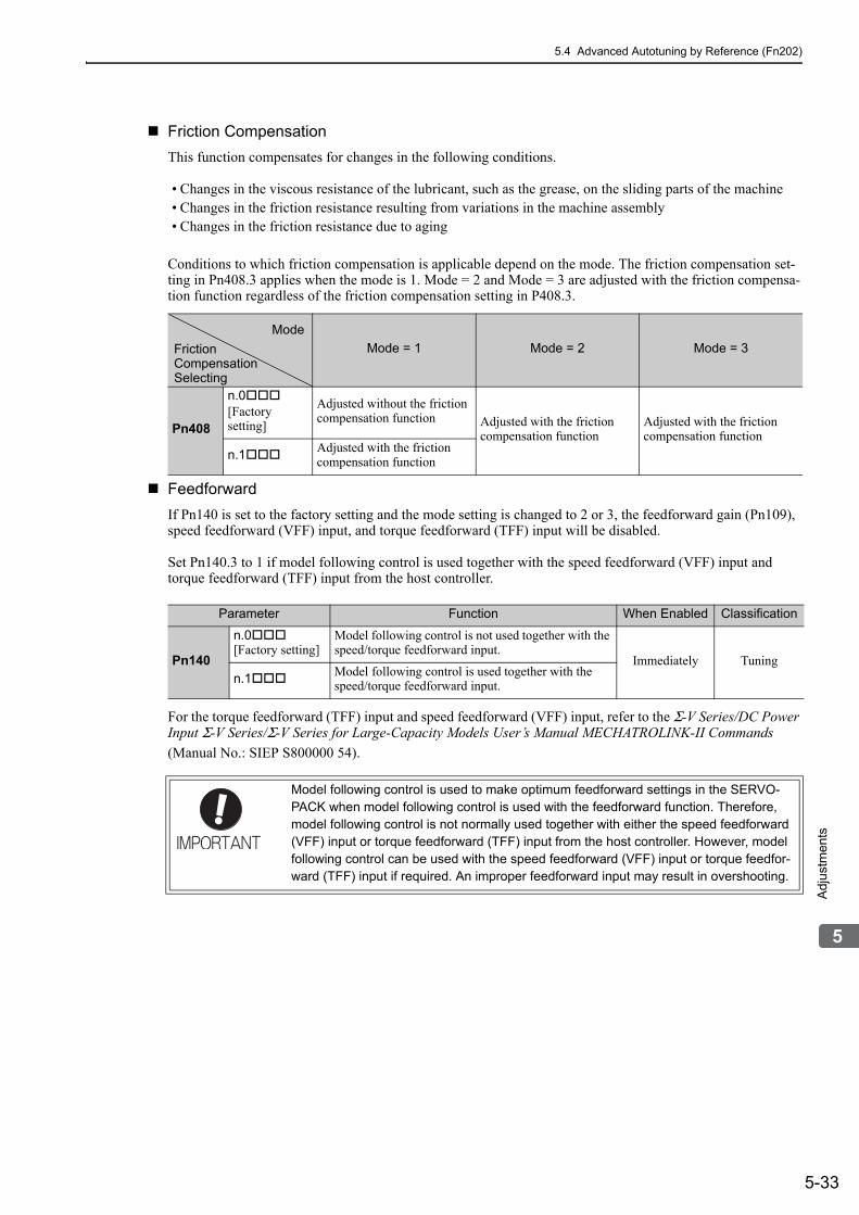
5.4 Advanced Autotuning by Reference (Fn202)
5-33
5
Adj
ustm
ents
Friction Compensation
This function compensates for changes in the following conditions.
• Changes in the viscous resistance of the lubricant, such as the grease, on the sliding parts of the machine• Changes in the friction resistance resulting from variations in the machine assembly• Changes in the friction resistance due to aging
Conditions to which friction compensation is applicable depend on the mode. The friction compensation set-ting in Pn408.3 applies when the mode is 1. Mode = 2 and Mode = 3 are adjusted with the friction compensa-tion function regardless of the friction compensation setting in P408.3.
Feedforward
If Pn140 is set to the factory setting and the mode setting is changed to 2 or 3, the feedforward gain (Pn109), speed feedforward (VFF) input, and torque feedforward (TFF) input will be disabled.
Set Pn140.3 to 1 if model following control is used together with the speed feedforward (VFF) input and torque feedforward (TFF) input from the host controller.
For the torque feedforward (TFF) input and speed feedforward (VFF) input, refer to the Σ-V Series/DC Power Input Σ-V Series/Σ-V Series for Large-Capacity Models User’s Manual MECHATROLINK-II Commands
(Manual No.: SIEP S800000 54).
Mode = 1 Mode = 2 Mode = 3
Pn408
n.0[Factory setting]
Adjusted without the friction compensation function Adjusted with the friction
compensation functionAdjusted with the friction compensation function
n.1Adjusted with the friction compensation function
Mode
FrictionCompensationSelecting
Parameter Function When Enabled Classification
Pn140
n.0[Factory setting]
Model following control is not used together with the speed/torque feedforward input.
Immediately Tuning
n.1 Model following control is used together with the speed/torque feedforward input.
Model following control is used to make optimum feedforward settings in the SERVO-PACK when model following control is used with the feedforward function. Therefore, model following control is not normally used together with either the speed feedforward (VFF) input or torque feedforward (TFF) input from the host controller. However, model following control can be used with the speed feedforward (VFF) input or torque feedfor-ward (TFF) input if required. An improper feedforward input may result in overshooting.

5 Adjustments
5.4.3 Related Parameters
5-34
5.4.3 Related ParametersThe following table lists parameters related to this function and their possibility of being changed while exe-cuting this function or of being changed automatically after executing this function.
• Parameters related to this functionThese are parameters that are used or referenced when executing this function.
• Allowed changes during execution of this functionYes: Parameters can be changed using SigmaWin+ while this function is being executed.No: Parameters cannot be changed using SigmaWin+ while this function is being executed.
• Automatic changes after execution of this functionYes: Parameter set values are automatically set or adjusted after execution of this function.No: Parameter set values are not automatically set or adjusted after execution of this function.
Parameter Name Mid-execution changes
Automatic changes
Pn100 Speed Loop Gain No Yes
Pn101 Speed Loop Integral Time Constant No Yes
Pn102 Position Loop Gain No Yes
Pn103 Moment of Inertia Ratio No No
Pn121 Friction Compensation Gain No Yes
Pn123 Friction Compensation Coefficient No Yes
Pn124 Friction Compensation Frequency Correction No No
Pn125 Friction Compensation Gain Correction No Yes
Pn401 Torque Reference Filter Time Constant No Yes
Pn408 Torque Related Function Switch Yes Yes
Pn409 1st Notch Filter Frequency No Yes
Pn40A 1st Notch Filter Q Value No Yes
Pn40C 2nd Notch Filter Frequency No Yes
Pn40D 2nd Notch Filter Q Value No Yes
Pn140 Model Following Control Related Switch Yes Yes
Pn141 Model Following Control Gain No Yes
Pn142 Model Following Control Gain Compensation No Yes
Pn143 Model Following Control Bias (Forward Direction) No Yes
Pn144 Model Following Control Bias (Reverse Direction) No Yes
Pn145 Vibration Suppression 1 Frequency A No Yes
Pn146 Vibration Suppression 1 Frequency B No Yes
Pn147 Model Following Control Speed Feedforward Compensation No Yes
Pn160 Anti-Resonance Control Related Switch Yes Yes
Pn161 Anti-Resonance Frequency No Yes
Pn163 Anti-Resonance Damping Gain No Yes

5.5 One-parameter Tuning (Fn203)
5-35
5
Adj
ustm
ents
5.5 One-parameter Tuning (Fn203)Adjustments with one-parameter tuning are described below.
5.5.1 One-parameter TuningOne-parameter tuning is used to manually make tuning level adjustments during operation with a position ref-erence or speed reference input from the host controller.
One-parameter tuning enables automatically setting related servo gain settings to balanced conditions by adjusting one or two tuning levels.
One-parameter tuning performs the following adjustments.
• Gains (e.g., position loop gain and speed loop gain)• Filters (torque reference filter and notch filter)• Friction compensation• Anti-resonance control
Refer to 5.5.4 Related Parameters for parameters used for adjustments.
Perform one-parameter tuning if satisfactory response characteristics is not obtained with advanced autotun-ing or advanced autotuning by reference.
To fine-tune each servo gain after one-parameter tuning, refer to 5.8 Additional Adjustment Function.
CAUTION• Vibration or overshooting may occur during adjustment. To ensure safety, perform one-parameter tuning in
a state where the SERVOPACK can come to an emergency stop at any time.

5 Adjustments
5.5.1 One-parameter Tuning
5-36
(1) Preparation
Check the following settings before performing one-parameter tuning. The message “NO-OP” indicating that the settings are not appropriate will be displayed, if all of the following conditions are not met.
• The test without a motor function must be disabled (Pn00C.0 = 0).• The write prohibited setting (Fn010) must be set to Write permitted (P.0000).• The tuning-less function must be disabled (Pn170.0 = 0). • The tuning mode must be set to 0 or 1 when performing speed control.
(2) Restrictions When Using an Encoder
With this function, the following restrictions are applied in accordance with the version number of the SER-VOPACK software and the encoder being used.
The applicable servomotor depends on the type of encoder used.
• 13-bit encoder: SGMJV-A• 20-bit or 17-bit encoder: SGMV-D, SGMV-3
SGMPS-C, SGMPS-2
∗1. The software version number of your SERVOPACK can be checked with Fn012.∗2. If any mode other than Tuning Mode 1 is selected, tuning will fail and result in an error.∗3. Model following control type is not used.∗4. Position errors may result in overshooting when positioning. The positioning time may be extended if the positioning
completed width (Pn522) is set to a small value.∗5. Model following control type 2 can suppress overshooting resulting from position errors better than Type 1. If com-
patibility with SERVOPACK version 0007 or earlier is required, use model following control type 1 (Pn14F.0 = 0).
The control related switch (Pn14F) was added to SERVOPACK software version 0008 or later.
Software Version*1
13-bit Encoder 20-bit or 17-bit Encoder
ModeModel Following
Control Type ModeModel Following
Control Type
Version 0007 or ear-lier
Tuning mode can be set to only 0 or 1.*2
–*3 No restrictions
Type 1*4
Version 0008 or lat-er No restrictions
Type 1 or 2 [Factory setting]*5
Parameter Function When Enabled Classification
Pn14Fn.0 Model following control type 1
After restart Tuningn.1 [Factory setting]
Model following control type 2

5.5 One-parameter Tuning (Fn203)
5-37
5
Adj
ustm
ents
5.5.2 One-parameter Tuning ProcedureThe following procedure is used for one-parameter tuning.
There are the following two operation procedures depending on the tuning mode being used.
• When the tuning mode is set to 0 or 1, the model following control will be disabled and one-parameter tun-ing will be used as the tuning method for applications other than positioning.
• When the tuning mode is set to 2 or 3, the model following control will be enabled and it can be used for tuning for positioning.
One-parameter tuning is performed from the digital operator (option) or SigmaWin+.
Make sure that the moment of inertia ratio (Pn103) is set correctly using advance autotuning before beginning operation.
The following section provides the operating procedure from the digital operator.
Refer to the Σ-V Series User’s Manual, Operation of Digital Operator (No.: SIEP S800000 55) for basic key operations of the digital operator.
(1) Digital Operator Operating Procedure
Setting the Tuning Mode 0 or 1
CAUTION• When using the MP2000 Series with phase control, select the tuning mode = 0 or 1. If 2 or 3 is selected,
phase control of the MP2000 Series may not be possible.
Step Display after Operation Keys Operation
1
Press the Key to view the main menu for the utility function.
Press the or Key to move through the list and select Fn203.
2
Press the Key to display the moment of inertia ratio set in Pn103 at present. Move the digit with the
or Key and change the value with the
or Key.
3 Press the Key to display the initial setting screen for Fn203 (One-parameter Tuning).
4 Press the , , or Key and set the items in steps 4-1 and 4-2.
4-1
Tuning ModeSelect the tuning mode. Select the tuning mode 0 or 1.Tuning Mode = 0: Makes adjustments giving priority to stability.Tuning Mode = 1: Makes adjustments giving priority to responsiveness.
4-2
Type SelectionSelect the type according to the machine element to be driven. If there is noise or the gain does not increase, better results may be obtained by changing the rigidity type.Type = 1: For belt drive mechanismsType = 2: For ball screw drive mechanisms [Factory setting]Type = 3: For rigid systems in which the servomotor is directly coupled to the machine (without gear or other transmissions).
Status Display

5 Adjustments
5.5.2 One-parameter Tuning Procedure
5-38
5 −
If the servomotor power is OFF, send an SV_ON command from the host controller. The display will change from "BB" to "RUN."If the servomotor power is ON, go to step 6.
6 Press the Key to display the set value.
7 Press the Key again to display the LEVEL set-ting screen.
8
If readjustment is required, select the digit with the or Key or change the LEVEL with the
or Key. Check the response.If readjustment is not required, go to step 9.Note: The higher the level, the greater the respon-
siveness will be. If the value is too large, how-ever, vibration will occur.
• If vibration occurs, press the Key. The SER-VOPACK will automatically detect the vibration frequencies and make notch filter or an anti-reso-nance control settings. When the notch filter is set, "NF1" or "NF2" will be displayed on the bottom row. When the anti-resonance control is set, "ARES" will be displayed in the lower right corner.
• If the vibration is great, the vibration frequency will be detected automatically even if the Key is not pressed and a notch filter or an anti-reso-nance control will be set.
9 Press the Key. A confirmation screen will be dis-played after LEVEL adjustment.
10
• Press the Key to save the adjusted values. After the data is saved, “DONE” will flash for approximately two seconds and then “RUN” will be displayed.
• To return to the previous value, press the Key.
• Press the Key to readjust the level without saving the values.
11Press the Key to complete the one-parameter tuning operation. The screen in step 1 will appear again.
Note: The status display will always be RUN when the servomotor power is ON.
(cont’d)
Step Display after Operation Keys Operation
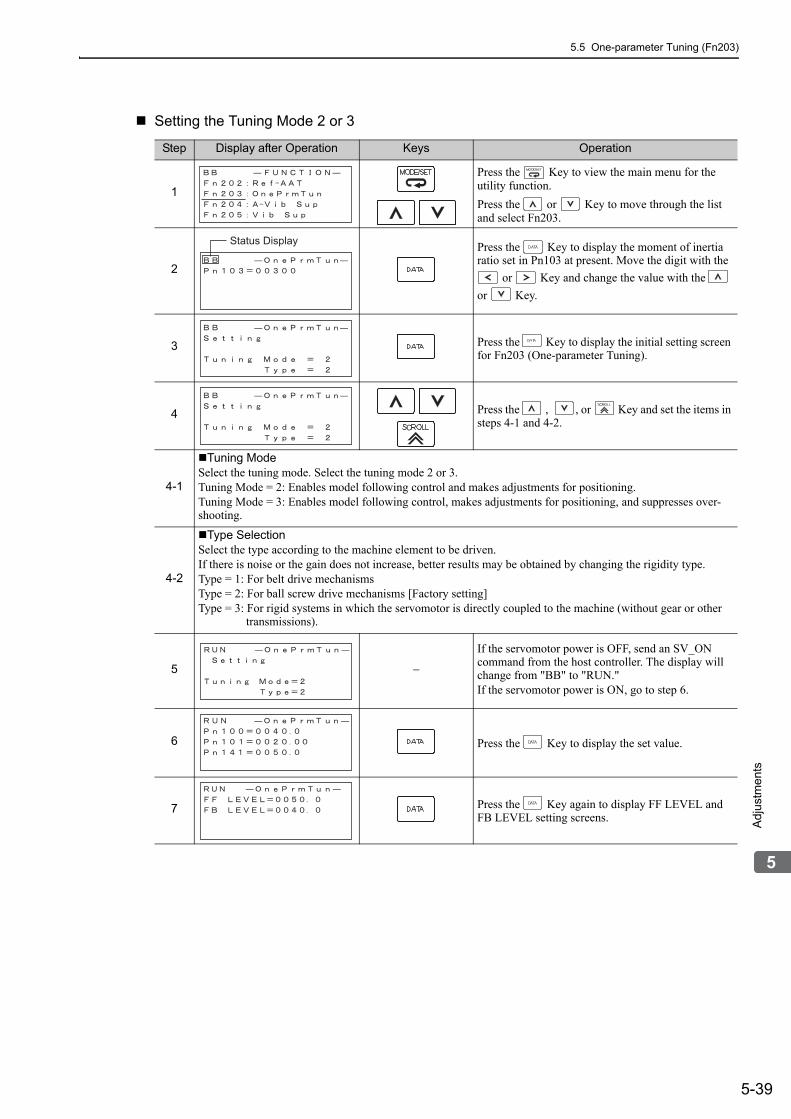
5.5 One-parameter Tuning (Fn203)
5-39
5
Adj
ustm
ents
Setting the Tuning Mode 2 or 3
Step Display after Operation Keys Operation
1
Press the Key to view the main menu for the utility function.
Press the or Key to move through the list and select Fn203.
2
Press the Key to display the moment of inertia ratio set in Pn103 at present. Move the digit with the
or Key and change the value with the
or Key.
3 Press the Key to display the initial setting screen for Fn203 (One-parameter Tuning).
4 Press the , , or Key and set the items in steps 4-1 and 4-2.
4-1
Tuning ModeSelect the tuning mode. Select the tuning mode 2 or 3.Tuning Mode = 2: Enables model following control and makes adjustments for positioning.Tuning Mode = 3: Enables model following control, makes adjustments for positioning, and suppresses over-shooting.
4-2
Type SelectionSelect the type according to the machine element to be driven.If there is noise or the gain does not increase, better results may be obtained by changing the rigidity type.Type = 1: For belt drive mechanismsType = 2: For ball screw drive mechanisms [Factory setting]Type = 3: For rigid systems in which the servomotor is directly coupled to the machine (without gear or other transmissions).
5 −
If the servomotor power is OFF, send an SV_ON command from the host controller. The display will change from "BB" to "RUN."If the servomotor power is ON, go to step 6.
6 Press the Key to display the set value.
7 Press the Key again to display FF LEVEL and FB LEVEL setting screens.
Status Display

5 Adjustments
5.5.2 One-parameter Tuning Procedure
5-40
8
If readjustment is required, select the digit with the
or Key or change the FF LEVEL and FB
LEVEL with the or Key. Check the response.Refer to 5.5.3 One-parameter Tuning Example for details.If readjustment is not required, go to step 9.Note: The higher the FF LEVEL, the positioning time
will be shorter and the response will be better. If the level is too high, however, overshooting or vibration may occur. Overshooting will be reduced if the FB LEVEL is increased.
<NOTE>• If the FF LEVEL is changed when the servomotor
is in operation, it will not be reflected immediately. The changes will be effective after the servomotor comes to a stop with no reference input and then the servomotor starts operation.If the FF LEVEL is changed too much during oper-ation, vibration may occur because the responsive-ness changes rapidly when the settings become effective.
• The message “FF LEVEL” flashes until the SER-VOPACK reaches the effective FF LEVEL. If the servomotor does not stop within approximately 10 seconds after changing the setting, a timeout will occur. The setting will be returned to the previous value.
If Vibration Occurs
• If vibration occurs, press the Key. The SER-VOPACK will automatically detect the vibration frequencies and set the notch filters or anti-reso-nance control. When the notch filter is set, “NF1” and “NF2” are displayed on the bottom row. When the anti-resonance control is set, “ARES” will be displayed on the bottom row.
If Vibration Is Large
• Even if the Key is not pressed, the SERVO-PACK will automatically detect the vibration fre-quencies and make notch filter or anti-resonance control settings.
9 Press the Key to display the confirmation screen after level adjustment.
10
• Press the Key to save the adjusted values. After the data is saved, “DONE” will flash for approximately two seconds and then “RUN” will be displayed.
• To return to the previous value, press the Key.
• Press the Key to readjust the level without saving the values.
11Press the Key to complete the one-parameter tuning operation. The screen in step 1 will appear again.
Note: The status display will always be RUN when the servomotor power is ON.
(cont’d)
Step Display after Operation Keys Operation
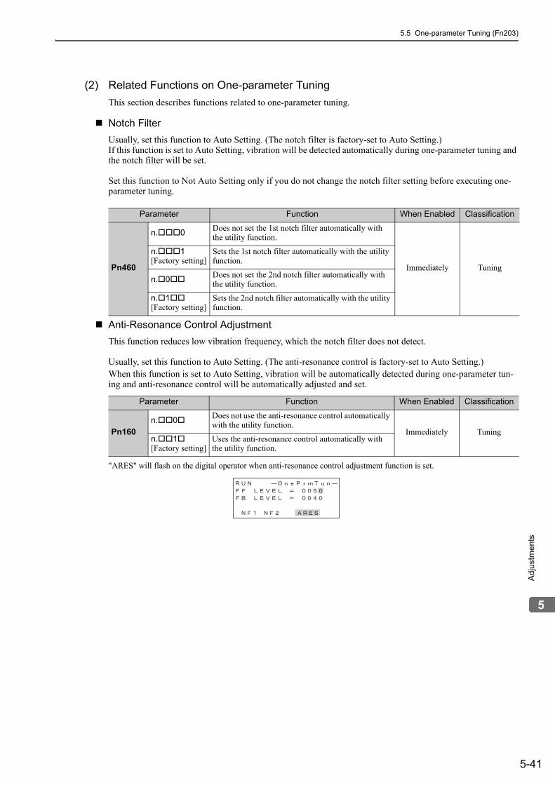
5.5 One-parameter Tuning (Fn203)
5-41
5
Adj
ustm
ents
(2) Related Functions on One-parameter Tuning
This section describes functions related to one-parameter tuning.
Notch Filter
Usually, set this function to Auto Setting. (The notch filter is factory-set to Auto Setting.)If this function is set to Auto Setting, vibration will be detected automatically during one-parameter tuning and the notch filter will be set.
Set this function to Not Auto Setting only if you do not change the notch filter setting before executing one-parameter tuning.
Anti-Resonance Control Adjustment
This function reduces low vibration frequency, which the notch filter does not detect.
Usually, set this function to Auto Setting. (The anti-resonance control is factory-set to Auto Setting.)When this function is set to Auto Setting, vibration will be automatically detected during one-parameter tun-ing and anti-resonance control will be automatically adjusted and set.
"ARES" will flash on the digital operator when anti-resonance control adjustment function is set.
Parameter Function When Enabled Classification
Pn460
n.0 Does not set the 1st notch filter automatically with the utility function.
Immediately Tuning
n.1[Factory setting]
Sets the 1st notch filter automatically with the utility function.
n.0Does not set the 2nd notch filter automatically with the utility function.
n.1[Factory setting]
Sets the 2nd notch filter automatically with the utility function.
Parameter Function When Enabled Classification
Pn160n.0 Does not use the anti-resonance control automatically
with the utility function.Immediately Tuning
n.1[Factory setting]
Uses the anti-resonance control automatically with the utility function.

5 Adjustments
5.5.2 One-parameter Tuning Procedure
5-42
Friction Compensation
This function compensates for changes in the following conditions.
• Changes in the viscous resistance of the lubricant, such as the grease, on the sliding parts of the machine• Changes in the friction resistance resulting from variations in the machine assembly• Changes in the friction resistance due to aging
Conditions to which friction compensation is applicable depend on the tuning mode. The friction compensa-tion setting in F408.3 applies when the mode is 0 or 1. Tuning Mode = 2 and Tuning Mode = 3 are adjusted with the friction compensation function regardless of the friction compensation setting in P408.3.
Feedforward
If Pn140 is set to the factory setting and the tuning mode setting is changed to 2 or 3, the feedforward gain (Pn109), speed feedforward (VFF) input, and torque feedforward (TFF) input will be disabled.
Set Pn140.3 to 1 if model following control is used together with the speed feedforward (VFF) input and
torque feedforward (TFF) input from the host controller.
For the torque feedforward (TFF) input and speed feedforward (VFF) input, refer to the Σ-V Series/DC Power Input Σ-V Series/Σ-V Series for Large-Capacity Models User’s Manual MECHATROLINK-II Commands
(Manual No.: SIEP S800000 54).
Tuning Mode = 0 Tuning Mode = 1 Tuning Mode = 2 Tuning Mode = 3
Pn408
n.0[Factory setting]
Adjusted without the friction compensation function
Adjusted without the friction compensation function Adjusted with the
friction compensation function
Adjusted with the friction compensation function
n.1Adjusted with the friction compensation function
Adjusted with the friction compensation function
ModeFrictionCompensationSelecting
Parameter Function When Enabled Classification
Pn140
n.0[Factory setting]
Model following control is not used together with the speed/torque feedforward input.
Immediately Tuning
n.1 Model following control is used together with the speed/torque feedforward input.
Model following control is used to make optimum feedforward settings in the SERVO-PACK when model following control is used with the feedforward function. Therefore, model following control is not normally used together with either the speed feedforward (VFF) input or torque feedforward (TFF) input from the host controller. However, model following control can be used with the speed feedforward (VFF) input or torque feedfor-ward (TFF) input if required. An improper feedforward input may result in overshooting.

5.5 One-parameter Tuning (Fn203)
5-43
5
Adj
ustm
ents
5.5.3 One-parameter Tuning ExampleThis section describes the procedure to adjust the FF LEVEL and FB LEVEL after step 8 of 5.5.2 (1) Set-ting the Tuning Mode 2 or 3 and the procedure to save the values after adjustment to the SERVOPACK.
<NOTE>Positioning time will be shortened if the FF LEVEL is increased. But overshooting and vibrations will occur if it is increased too much.Overshooting will be reduced if the FB LEVEL is increased.
Step Panel Display after Operation or Measurement Results Display Example Operation
1 –Perform steps 1 through 7 of 5.5.2 (1) Setting the Tuning Mode 2 or 3.
2
Measure the positioning time.If the measurement results and specifications are met, this concludes the tuning. Go to step 8.If readjustment is required, go to the next step.
3
First input the reference from the host controller, and then increase the FF LEVEL with the digital operator to shorten the positioning time.
Note 1. If the FF LEVEL is changed when the servo-motor is in operation, this value is not effec-tive immediately. The changes will be effective after the servomotor comes to a stop with no reference input and then the ser-vomotor starts operation.
2. If the FF LEVEL is changed too much during operation, vibration may occur because the responsiveness changes rapidly when the settings become effective.
3. If large vibrations occur, the SERVOPACK will automatically detect the vibration fre-quencies and set the notch filters or anti-res-onance control. When a notch filter is set, “NF1” and “NF2” are displayed on the bot-tom row of the digital operator. When anti-resonance control is set, “ARES” is dis-played on the bottom row of the digital oper-ator.
<NOTE>
• Move the digit with the or Key and
increase or decrease the value with the or Key.
• The message “FF LEVEL” flashes until the SER-VOPACK reaches the effective FF LEVEL. If the servomotor does not stop within approximately 10 seconds after changing the setting, a timeout will occur. The setting will be returned to the previous value.
Positioning completion signal
Position deviation
Reference speedPositioning time

5 Adjustments
5.5.3 One-parameter Tuning Example
5-44
4
In this measurement results example, the positioning time has decreased over the previous time, but over-shooting has occurred.
Measure the positioning time with a measuring instru-ment.If the measurement results and specifications are met, this concludes the tuning. Go to step 8.Go to the next step if overshooting occurs before the specifications are met.
5
First input the reference from the host controller, then increase the FB LEVEL with the digital operator to reduce overshooting.
<NOTE>
• Move the digit with the or Key and
increase or decrease the value with the or Key.
6
Measure the positioning time with a measuring instru-ment.If the measurement results and specifications are met, this concludes the tuning. Go to step 8.Go back to step 3 if overshooting occurs before the specifications are met.Go to the next step if vibrations occur before over-shooting stops.
7
Press the Key on the digital operator.The SERVOPACK will automatically detect the vibra-tion frequencies and set the notch filters or an anti-res-onance control. When a notch filter is set, “NF1” or “NF2” is displayed on the bottom row of the digital operator. When anti-resonance control is set, “ARES” is displayed on the bottom row of the digital operator.<NOTE>If the vibration is large, a notch filter or anti-resonance control will be automatically set even if the Key is not pressed.
After making the setting, go back to step 6.
8 Press the Key. A confirmation screen will be dis-played after tuning.
9
Press the Key. The tuning results data will be saved in the SERVOPACK.When the data has been saved, “DONE” will flash for two seconds, and then “RUN” will be displayed.<NOTE>
• Press the Key to cancel saving the data.
• Press the Key to readjust the FF LEVEL and FB LEVEL without saving the data.
(cont’d)
Step Panel Display after Operation or Measurement Results Display Example
Operation
Overshooting

5.5 One-parameter Tuning (Fn203)
5-45
5
Adj
ustm
ents
5.5.4 Related ParametersThe following table lists parameters related to this function and their possibility of being changed while exe-cuting this function or of being changed automatically after executing this function.
• Parameters related to this functionThese are parameters that are used or referenced when executing this function.
• Allowed changes during execution of this functionYes: Parameters can be changed using SigmaWin+ while this function is being executed.No: Parameters cannot be changed using SigmaWin+ while this function is being executed.
• Automatic changes after execution of this functionYes: Parameter set values are automatically set or adjusted after execution of this function.No: Parameter set values are not automatically set or adjusted after execution of this function.
Parameter Name Mid-execution changes
Automatic changes
Pn100 Speed Loop Gain No Yes
Pn101 Speed Loop Integral Time Constant No Yes
Pn102 Position Loop Gain No Yes
Pn103 Moment of Inertia Ratio No No
Pn121 Friction Compensation Gain No Yes
Pn123 Friction Compensation Coefficient No Yes
Pn124 Friction Compensation Frequency Correction No No
Pn125 Friction Compensation Gain Correction No Yes
Pn401 Torque Reference Filter Time Constant No Yes
Pn408 Torque Related Function Switch Yes Yes
Pn409 1st Notch Filter Frequency No Yes
Pn40A 1st Notch Filter Q Value No Yes
Pn40C 2nd Notch Filter Frequency No Yes
Pn40D 2nd Notch Filter Q Value No Yes
Pn140 Model Following Control Related Switch Yes Yes
Pn141 Model Following Control Gain No Yes
Pn142 Model Following Control Gain Compensation No Yes
Pn143 Model Following Control Bias (Forward Direction) No Yes
Pn144 Model Following Control Bias (Reverse Direction) No Yes
Pn145 Vibration Suppression 1 Frequency A No No
Pn146 Vibration Suppression 1 Frequency B No No
Pn147 Model Following Control Speed Feedforward Compensation No Yes
Pn160 Anti-Resonance Control Related Switch Yes Yes
Pn161 Anti-Resonance Frequency No Yes
Pn163 Anti-Resonance Damping Gain No Yes

5 Adjustments
5.6.1 Anti-Resonance Control Adjustment Function
5-46
5.6 Anti-Resonance Control Adjustment Function (Fn204)This section describes the anti-resonance control adjustment function.
5.6.1 Anti-Resonance Control Adjustment FunctionThe anti-resonance control adjustment function increases the effectiveness of the vibration suppression after one-parameter tuning. This function is effective in supporting anti-resonance control adjustment if the vibra-tion frequencies are from 100 to 1000 Hz.
This function rarely needs to be used because it is automatically set by the advanced autotuning or advanced autotuning by reference input. Use this function only if fine-tuning is required, or vibration detection is failed and readjustment is required.
Perform one-parameter tuning (Fn203) or use another method to improve the response characteristics after performing this function. If the anti-resonance gain is increased with one-parameter tuning performed, vibra-tion may result again. If that occurs, perform this function again to fine-tune the settings.
(1) Before Performing Anti-Resonance Control Adjustment Function
Check the following settings before performing anti-resonance control adjustment function.The message “NO-OP” indicating that the settings are not appropriate will be displayed, if all of the following conditions are not met.
• The tuning-less function must be disabled (Pn170.0 = 0).• The test without a motor function must be disabled (Pn00C.0 = 0).• The control must not be set to torque control.• The write prohibited setting (Fn010) must be set to Write permitted (P.0000).
CAUTION• If this function is executed, related parameters will be set automatically. Therefore, there will be a large
response change after this function is executed. Enable the function in a state where the machine can come to an emergency stop at any time to ensure the safety operation of the machine.
• Be sure to set a suitable value for the moment of inertia ratio (Pn103) using advanced autotuning before executing the anti-resonance control adjustment function. If the setting greatly differs from the actual moment of inertia ratio, normal control of the machine may not be possible, and vibration may result.
• This function detects vibration between 100 and 1000 Hz. Vibration will not be detected for frequencies outside of this range, and instead, "F----" will be displayed. If that occurs, use one-parameter tuning with tuning mode 2 selected to automatically set a notch filter or use the vibration suppression function (Fn205).
• Vibration can be reduced more effectively by increasing the anti-resonance damping gain (Pn163). The amplitude of vibration may become larger if the damping gain is excessively high. Increase the damping gain from about 0 to 200% in 10% increments while checking the effect of vibration reduction. If the effect of vibration reduction is still insufficient at a gain of 200%, cancel the setting, and lower the control gain using a different method, such as one-parameter tuning.

5.6 Anti-Resonance Control Adjustment Function (Fn204)
5-47
5
Adj
ustm
ents
5.6.2 Anti-Resonance Control Adjustment Function Operating ProcedureWith this function, an operation reference is sent, and the function is executed while vibration is occurring.
Anti-resonance control adjustment function is performed from the digital operator (option) or SigmaWin+.The following methods can be used for the anti-resonance control adjustment function.
• Using anti-resonance control for the first time• With undetermined vibration frequency• With determined vibration frequency
• For fine-tuning after adjusting the anti-resonance control
The following describes the operating procedure from the digital operator.
Refer to the Σ-V Series User’s Manual, Operation of Digital Operator (No.: SIEP S800000 55) for basic key operations of the digital operator.
(1) Using Anti-Resonance Control for the First Time
With Undetermined Vibration Frequency
Step Display after Operation Keys Operation
1
Press the Key to view the main menu for the utility function.
Use the or Key to move through the list, select Fn204.
2Press the Key to display the tuning mode selec-tion screen for Fn204 (anti-resonance control adjust-ment function).
3 Press the or Key and set the tuning mode "0."
4
Press the Key while "Tuning Mode = 0" is dis-played. The screen shown on the left will appear. The detection of vibration frequencies will start and "freq" will flash. Return to step 3 if vibration is not detected. Note: If vibration is not detected even when vibration
is occurring, lower the vibration detection sen-sitivity (Pn311). When this parameter is low-ered, the detection sensitivity will be increased. Vibration may not be detected accurately if too small value is set.
5 −
The vibration frequency will be displayed in “freq” if vibration is detected.
Example of measured waveform
Status Display
ErrorErrorError
Torque reference
Positioning completedPositioning completedsignalsignal
Torque reference
Positioning completedsignal

5 Adjustments
5.6.2 Anti-Resonance Control Adjustment Function Operating Procedure
5-48
6 Press the Key. The cursor will move to "damp," and the flashing of "freq" will stop.
7
Select the digit with the or Key, and press
the or Key to set the damping gain.
Example of measured waveformNote: Increase the damping gain from about 0 to
200% in 10% increments while checking the effect of vibration reduction. If vibration reduc-tion is still insufficient at a gain of 200%, can-cel the setting, and lower the control gain by using a different method, such as one-parame-ter tuning.
8
If fine tuning of the frequency is necessary, press the
Key. The cursor will move from "damp" to "freq." If fine-tuning is not necessary, skip step 9 and go to step 10.
9Select the digit with the or Key, and press
the or Key to fine-tune the frequency.
10Press the Key to save the settings. "DONE" will flash for approximately two seconds and "RUN" will be displayed.
11Press the Key to complete the anti-resonance control adjustment function. The screen in step 1 will appear again.
(cont’d)
Step Display after Operation Keys Operation
ErrorError
Torque referenceTorque reference
Positioning completedPositioning completedsignalsignal
Error
Torque reference
Positioning completedsignal

5.6 Anti-Resonance Control Adjustment Function (Fn204)
5-49
5
Adj
ustm
ents
With Determined Vibration Frequency
Step Display after Operation Keys Operation
1
Press the Key to view the main menu for the utility function.
Use the or Key to move through the list, select Fn204.
2 Press the Key to display the tuning mode selec-tion screen for Fn204 (anti-resonance control adjust-ment function).
3 Press the or Key and set the tuning mode "1."
4
Press the Key while "Tuning Mode = 1" is dis-played. The screen shown on the left will appear and "freq" will flash.
Example of measured waveform
5Select the digit with the or Key, and press
the or Key to adjust the frequency.
6 Press the Key. The cursor will move to "damp."
ErrorErrorError
Torque reference
Positioning completedPositioning completedsignalsignal
Torque reference
Positioning completedsignal

5 Adjustments
5.6.2 Anti-Resonance Control Adjustment Function Operating Procedure
5-50
(2) For Fine-tuning After Adjusting the Anti-Resonance Control
7
Select the digit with the or Key, and press
the or Key to adjust the damping gain.
Example of measured waveformNote: Increase the damping gain from about 0 to
200% in 10% increments while checking the effect of vibration reduction. If vibration reduc-tion is still insufficient at a gain of 200%, can-cel the setting, and lower the control gain by using a different method, such as one-parame-ter tuning.
8
If fine tuning of the frequency is necessary, press the
Key. The cursor will move from "damp" to "freq." If fine-tuning is not necessary, skip step 9 and go to step 10.
9Select the digit with the or Key, and press
the or Key to fine-tune the frequency.
10Press the Key to save the settings. "DONE" will flash for approximately two seconds and "RUN" will be displayed.
11Press the Key to complete the anti-resonance control adjustment function. The screen in step 1 will appear again.
Step Display after Operation Keys Operation
1
Press the Key to view the main menu for the utility function.
Use the or Key to move through the list, select Fn204.
2 Press the Key to display the "Tuning Mode = 1" as shown on the left.
3Press the Key while "Tuning Mode = 1" is dis-played. The screen shown on the left will appear and "damp" will flash.
(cont’d)
Step Display after Operation Keys Operation
ErrorError
Torque referenceTorque reference
Positioning completedPositioning completedsignalsignal
Error
Torque reference
Positioning completedsignal

5.6 Anti-Resonance Control Adjustment Function (Fn204)
5-51
5
Adj
ustm
ents
5.6.3 Related ParametersThe following table lists parameters related to this function and their possibility of being changed while exe-cuting this function or of being changed automatically after executing this function.
• Parameters related to this functionThese are parameters that are used or referenced when executing this function.
• Allowed changes during execution of this functionYes : Parameters can be changed using SigmaWin+ while this function is being executed.No : Parameters cannot be changed using SigmaWin+ while this function is being executed.
• Automatic changes after execution of this functionYes : Parameter set values are automatically set or adjusted after execution of this function.No: Parameter set values are not automatically set or adjusted after execution of this function.
4
Select the digit with the or Key, and press
the or Key to set the damping gain.Note: Increase the damping gain from about 0 to
200% in 10% increments while checking the effect of vibration reduction. If vibration reduc-tion is still insufficient at a gain of 200%, can-cel the setting, and lower the control gain by using a different method, such as one-parame-ter tuning.
5
If fine tuning of the frequency is necessary, press the
Key. The cursor will move from "damp" to "freq." If fine-tuning is not necessary, skip step 6 and go to step 7.
6Select the digit with the or Key, and press
the or Key to fine-tune the frequency.
7Press the Key to save the settings. "DONE" will flash for approximately two seconds and "RUN" will be displayed.
8Press the Key to complete the anti-resonance control adjustment function. The screen in step 1 will appear again.
(cont’d)
Step Display after Operation Keys Operation
Parameter Name Mid-execution changes
Automatic changes
Pn160 Anti-Resonance Control Related Switch Yes Yes
Pn161 Anti-Resonance Frequency No Yes
Pn162 Anti-Resonance Gain Compensation Yes No
Pn163 Anti-Resonance Damping Gain No Yes
Pn164 Anti-Resonance Filter Time Constant 1 Compensation Yes No
Pn165 Anti-Resonance Filter Time Constant 2 Compensation Yes No

5 Adjustments
5.7.1 Vibration Suppression Function
5-52
5.7 Vibration Suppression Function (Fn205)The vibration suppression function is described in this section.
5.7.1 Vibration Suppression FunctionThe vibration suppression function suppresses transitional vibration at frequency as low as 1 to 100 Hz that is generated mainly when positioning if the machine stand vibrates.
This function is set automatically when advanced autotuning or advanced autotuning by reference is executed. In most cases, this function is not necessary. Use this function only if fine-tuning is required or readjustment is required as a result of a failure to detect vibration.
Perform one-parameter tuning (Fn203) if required to improve the response characteristics after performing this function.
(1) Preparation
Check the following settings before performing the vibration suppression function.The message “NO-OP” indicating that the settings are not appropriate will be displayed, if all of the following conditions are not met.
• The control must be set to position control.• The tuning-less function must be disabled (Pn170.0 = 0).• The test without a motor function must be disabled (Pn00C.0 = 0).• The write prohibited setting (Fn010) must be set to Write permitted (P.0000).
(2) Items Influencing Performance
If continuous vibration occurs when the servomotor is not rotating, the vibration suppression function cannot be used to suppress the vibration effectively. If the result is not satisfactory, perform anti-resonance control adjustment function (Fn204) or one-parameter tuning (Fn203).
(3) Detection of Vibration Frequencies
Frequency detection may not be possible if there is not enough vibration to affect the position error or the effect on the position error is minimal. The detection sensitivity can be adjusted by changing the setting for the remained vibration detection width (Pn560), which is set as a percentage of the positioning completed width (Pn522). Perform detection of vibration frequencies again after adjusting the remained vibration detection width (Pn560).
CAUTION• If this function is executed, related parameters will be set automatically. Therefore, there will be a large
response change after this function is enabled or disabled. Enable the function in a state where the machine can come to an emergency stop at any time to ensure the safety operation of the machine.
• Be sure to set a suitable value for the moment of inertia ratio (Pn103) using advanced autotuning before executing the vibration suppression function. If the setting greatly differs from the actual moment of inertia ratio, normal control of the SERVOPACK may not be possible, and vibration may result.
• Phase control of the MP2000 Series may not be possible, if the vibration suppression function is per-formed when using the MP2000 Series with phase control.
• This function detects vibration frequency between 1 to 100 Hz. Vibration will not be detected for frequencies outside of this range, and instead, "F-----" will be displayed.
• Frequency detection will not be performed if no vibration results from position error or the vibration frequencies are outside the range of detectable frequencies. If so, use a device, such as a displacement sensor or vibration sensor, to measure the vibration frequency.
• If vibration frequencies automatically detected are not suppressed, the actual fre-quency and the detected frequency may differ. Fine-tune the detected frequency if necessary.

5.7 Vibration Suppression Function (Fn205)
5-53
5
Adj
ustm
ents
Note: As a guideline, change the setting 10% at a time. The smaller the set value is, the higher the detection sensitivity will be. If the value is too small, however, the vibration may not be detected accurately.
The vibration frequencies that are automatically detected may vary somewhat with each positioning operation. Perform positioning several times and make adjustments while checking the effect of vibration suppression.
5.7.2 Vibration Suppression Function Operating ProcedureThe following procedure is used for vibration suppression function.
Vibration suppression function is performed from the digital operator (option) or SigmaWin+.
The operating procedure from the digital operator is described here.
Refer to the Σ-V Series User’s Manual, Operation of Digital Operator (No.: SIEP S800000 55) for basic key operations of the digital operator.
Note: If this function is aborted by pressing the MODE/SET Key, the SERVOPACK will continue operating until the ser-vomotor comes to a stop. After the servomotor stops, the set value will return to the previous value.
The operating flow of the vibration suppression function is shown below.
(1) Operating Flow
Pn560Remained Vibration Detection Width
ClassificationSetting Range Setting Unit Factory Setting When Enabled
1 to 3000 0.1% 400 Immediately Setup
Position
Vibration detected?
Execute steps 1 to 3 in the following page.
Completed
Adjust vibration using measuring device.
Execute steps 4 to 8 in the following page.
Yes
No

5 Adjustments
5.7.2 Vibration Suppression Function Operating Procedure
5-54
(2) Operating Procedure
Step Display after Operation Keys Operation
1 Input a operation reference and take the following steps while repeating positioning.
2
Press the Key to view the main menu for the utility function.
Use the or Key to move through the list, select Fn205.
3
Press the Key. The display shown on the left will appear.Measure f: Measurement frequencySetting f: Setting frequency [Factory-set to the set value for Pn145] If the setting frequency and actual operating fre-quency are different, "Setting" will flash.Note: Frequency detection will not be performed if
there is no vibration or the vibration frequency is outside the range of detectable frequencies. The following screen will be displayed if vibra-tion is not detected. If the vibration frequencies are not detected, prepare a means of detecting and measuring the vibration. When the vibra-tion frequencies are measured, go to step 5 and manually set the measured vibration frequency to “Setting f.”
4
Press the Key. The displayed “Measure f” value will be displayed as the “Setting f” value as well.
Example of measured waveform
5
If the vibration is not completely suppressed, select the digit with the or Key, and press the
or Key to fine-tune the frequency “setting f.” Skip this step and go to step 7 if the fine-tuning of the frequency is not necessary.Note: If the setting frequency and actual operating
frequency are different, "Setting" will flash.
Position Error
Torque reference
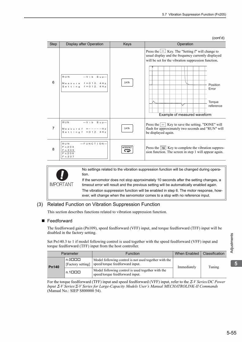
5.7 Vibration Suppression Function (Fn205)
5-55
5
Adj
ustm
ents
(3) Related Function on Vibration Suppression Function
This section describes functions related to vibration suppression function.
Feedforward
The feedforward gain (Pn109), speed feedforward (VFF) input, and torque feedforward (TFF) input will be disabled in the factory setting.
Set Pn140.3 to 1 if model following control is used together with the speed feedforward (VFF) input and torque feedforward (TFF) input from the host controller.
For the torque feedforward (TFF) input and speed feedforward (VFF) input, refer to the Σ-V Series/DC Power Input Σ-V Series/Σ-V Series for Large-Capacity Models User’s Manual MECHATROLINK-II Commands (Manual No.: SIEP S800000 54).
6
Press the Key. The "Setting f" will change to usual display and the frequency currently displayed will be set for the vibration suppression function.
Example of measured waveform
7Press the Key to save the setting. "DONE" will flash for approximately two seconds and "RUN" will be displayed again.
8 Press the Key to complete the vibration suppres-sion function. The screen in step 1 will appear again.
(cont’d)
Step Display after Operation Keys Operation
PositionError
Torquereference
No settings related to the vibration suppression function will be changed during opera-tion.
If the servomotor does not stop approximately 10 seconds after the setting changes, a timeout error will result and the previous setting will be automatically enabled again.
The vibration suppression function will be enabled in step 6. The motor response, how-ever, will change when the servomotor comes to a stop with no reference input.
Parameter Function When Enabled Classification
Pn140
n.0[Factory setting]
Model following control is not used together with the speed/torque feedforward input.
Immediately Tuning
n.1 Model following control is used together with the speed/torque feedforward input.

5 Adjustments
5.7.3 Related Parameters
5-56
5.7.3 Related ParametersThe following table lists parameters related to this function and their possibility of being changed while exe-cuting this function or of being changed automatically after executing this function.
• Parameters related to this functionThese are parameters that are used or referenced when executing this function.
• Allowed changes during execution of this functionYes: Parameters can be changed using SigmaWin+ while this function is being executed.No: Parameters cannot be changed using SigmaWin+ while this function is being executed.
• Automatic changes after execution of this functionYes: Parameter set values are automatically set or adjusted after execution of this function.No: Parameter set values are not automatically set or adjusted after execution of this function.
Model following control is used to make optimum feedforward settings in the SERVO-PACK when model following control is used with the feedforward function. Therefore, model following control is not normally used together with either the speed feedforward (VFF) input or torque feedforward (TFF) input from the host controller. However, model following control can be used with the speed feedforward (VFF) input or torque feedfor-ward (TFF) input if required. An improper feedforward input may result in overshooting.
Parameter Name Mid-execution changes
Automatic changes
Pn140 Model Following Control Related Switch Yes Yes
Pn141 Model Following Control Gain No Yes
Pn142 Model Following Control Gain Compensation No No
Pn143 Model Following Control Bias (Forward Direction) No No
Pn144 Model Following Control Bias (Reverse Direction) No No
Pn145 Vibration Suppression 1 Frequency A No Yes
Pn146 Vibration Suppression 1 Frequency B No Yes
Pn147 Model Following Control Speed Feedforward Compen-sation No No
Pn14A Vibration Suppression 2 Frequency No No
Pn14B Vibration Suppression 2 Compensation No No

5.8 Additional Adjustment Function
5-57
5
Adj
ustm
ents
5.8 Additional Adjustment FunctionThis section describes the functions that can be used for additional fine tuning after making adjustments with advanced autotuning, advanced autotuning by reference, or one-parameter tuning.
• Switching gain settings• Friction compensation• Current control mode selection• Current gain level setting• Speed detection method selection
5.8.1 Switching Gain SettingsTwo gain switching functions are available, manual switching and automatic switching. The manual switching function uses an external input signal to switch gains, and the automatic switching function switches gains automatically.
By using the gain switching function, the positioning time can be shortened by increasing the gain during posi-tioning and vibration can be suppressed by decreasing the gain while it is stopped.
Note: n.1 is reserved. Do not use.
For the gain combinations for switching, refer to (1) Gain Combinations for Switching.
For the manual gain switching, refer to (2) Manual Gain Switching.
For the automatic gain switching, refer to (3) Automatic Gain Switching.
(1) Gain Combinations for Switching
∗ The switching gain settings for the model following control gain and the model following control gain compensation are supported only for manual gain switching.To enable the gain switching of these parameters, a gain switching input signal must be sent, and the following condi-tions must be met.
• No command being executed.• Motor having been completely stopped.
If these conditions are not satisfied, the applicable parameters will not be switched although the other parameters shown in this table will be switched.
Parameter Function When Enabled Classification
Pn139n.0[Factory setting] Manual gain switching
Immediately Tuning
n.2 Automatic gain switching
SettingSpeed
Loop Gain
Speed Loop Integral Time
Constant
Position Loop Gain
Torque Ref-erence Filter
Model Fol-lowing Con-
trol Gain
Model Follow-ing Control
Gain Compen-sation
Friction Compensa-
tion Gain
Gain Setting 1
Pn100Speed Loop Gain
Pn101Speed Loop Integral Time Constant
Pn102Position Loop Gain
Pn401 Torque Refer-ence Filter Time Constant
Pn141*
Model Fol-lowing Con-trol Gain
Pn142*
Model Follow-ing Control Gain Compen-sation
Pn121Friction Compensa-tion Gain
Gain Setting 2
Pn1042nd Speed Loop Gain
Pn1052nd Speed Loop Integral Time Constant
Pn1062nd Posi-tion Loop Gain
Pn412 1st Step 2nd Torque Refer-ence Filter Time Constant
Pn148*
2nd Model Following Control Gain
Pn149*
2nd Model Fol-lowing Control Gain Compen-sation
Pn1222nd Gain for Friction Compensa-tion

5 Adjustments
5.8.1 Switching Gain Settings
5-58
(2) Manual Gain Switching
Manual gain switching uses G-SEL of OPTION field to switch between gain setting 1 and gain setting 2.
(3) Automatic Gain Switching
Automatic gain switching is enabled only in position control. The switching conditions are specified using the following settings.
Select one of the following settings for switching condition A.
Type Command Name Setting Meaning
Input G-SEL of OPTION field0 Switches to gain setting 1.
1 Switches to gain setting 2.
Parameter Setting Switching Condition Setting Switching Wait Time Switching Time
Pn139 n.2
Condition A satisfied. Gain setting 1 to gain setting 2
Pn135 Gain Switching Waiting Time 1
Pn131 Gain Switching Time 1
Condition A not satis-fied.
Gain setting 2 to gain setting 1
Pn136 Gain Switching Waiting Time 2
Pn132 Gain Switching Time 2
Parameter Switching Condition A for Position Control
For Other than Position Control (No Switching)
When Enabled Classification
Pn139
n.0[Factory setting]
Positioning completed signal (/COIN) ON Fixed in gain setting 1
Immediately Tuning
n.1Positioning completed signal (/COIN) OFF Fixed in gain setting 2
n.2 Positioning near signal (/NEAR) ON
Fixed in gain setting 1
n.3 Positioning near signal (/NEAR) OFF Fixed in gain setting 2
n.4No output for position reference filter and posi-tion reference input OFF
Fixed in gain setting 1
n.5 Position reference input ON Fixed in gain setting 2
Gain Settings 2
Pn104Pn105Pn106Pn122Pn412
Condition Asatisfied
Condition A not satisfied
Switching Waiting Time 1 Pn135Switching Time 1 Pn131
Switching Waiting Time 2 Pn136Switching Time 2 Pn132
Gain Settings 1
Pn100Pn101Pn102Pn121Pn401
Automatic Switching Pattern 1 (Pn139 = n.2)

5.8 Additional Adjustment Function
5-59
5
Adj
ustm
ents
Relationship between the Waiting and Switching Times for Gain Switching
In this example, the "positioning completed signal (/COIN) ON" condition is set as condition A for automatic gain switching. The position loop gain is switched from the value in Pn102 (position loop gain) to the value in Pn106 (2nd position loop gain). When the /COIN signal goes ON, the switching operation begins after the waiting time set in Pn135. The switching operation changes the position loop gain linearly from Pn102 to Pn106 within the switching time set in Pn131.
Note: Automatic gain switching is available in the PI and I-P controls (Pn10B).
(4) Related Parameters
Switching condition A satisfied
Switching TimePn131
SwitchingWaiting Time
Pn135Pn102
Position Loop Gain
Pn1062nd Position Loop Gain
/COIN
Pn100Speed Loop Gain
ClassificationSetting Range Setting Unit Factory Setting When Enabled
10 to 20000 0.1 Hz 400 Immediately Tuning
Pn101Speed Loop Integral Time Constant
ClassificationSetting Range Setting Unit Factory Setting When Enabled
15 to 51200 0.01 ms 2000 Immediately Tuning
Pn102Position Loop Gain
ClassificationSetting Range Setting Unit Factory Setting When Enabled
10 to 20000 0.1/s 400 Immediately Tuning
Pn401Torque Reference Filter Time Constant
ClassificationSetting Range Setting Unit Factory Setting When Enabled
0 to 65535 0.01 ms 100 Immediately Tuning
Pn141Model Following Control Gain
ClassificationSetting Range Setting Unit Factory Setting When Enabled
10 to 20000 0.1/s 500 Immediately Tuning
Pn142Model Following Control Gain Compensation
ClassificationSetting Range Setting Unit Factory Setting When Enabled
500 to 2000 0.1% 1000 Immediately Tuning
Pn121Friction Compensation Gain
ClassificationSetting Range Setting Unit Factory Setting When Enabled
10 to 1000 1% 100 Immediately Tuning
Pn1042nd Speed Loop Gain
ClassificationSetting Range Setting Unit Factory Setting When Enabled
10 to 20000 0.1 Hz 400 Immediately Tuning
Speed Position
Speed Position
Position
Speed Position Torque
Position
Position
Speed Position
Speed Position

5 Adjustments
5.8.1 Switching Gain Settings
5-60
(5) Parameters for Automatic Gain Switching
(6) Related Monitor
Note: When using the tuning-less function, gain setting 1 is enabled.
Pn1052nd Speed Loop Integral Time Constant
ClassificationSetting Range Setting Unit Factory Setting When Enabled
15 to 51200 0.01 ms 2000 Immediately Tuning
Pn1062nd Position Loop Gain
ClassificationSetting Range Setting Unit Factory Setting When Enabled
10 to 20000 0.1/s 400 Immediately Tuning
Pn412
1st Step 2nd Torque Reference Filter Time Constant Classification
Setting Range Setting Unit Factory Setting When Enabled
0 to 65535 0.01 ms 100 Immediately Tuning
Pn1482nd Model Following Control Gain
ClassificationSetting Range Setting Unit Factory Setting When Enabled
10 to 20000 0.1/s 500 Immediately Tuning
Pn1492nd Model Following Control Gain Compensation
ClassificationSetting Range Setting Unit Factory Setting When Enabled
500 to 2000 0.1% 1000 Immediately Tuning
Pn1222nd Gain for Friction Compensation
ClassificationSetting Range Setting Unit Factory Setting When Enabled
10 to 1000 1% 100 Immediately Tuning
(cont’d)
Speed Position
Position
Speed Position Torque
Position
Position
Speed Position
Pn131Gain Switching Time 1
ClassificationSetting Range Setting Unit Factory Setting When Enabled
0 to 65535 1 ms 0 Immediately Tuning
Pn132Gain Switching Time 2
ClassificationSetting Range Setting Unit Factory Setting When Enabled
0 to 65535 1 ms 0 Immediately Tuning
Pn135Gain Switching Waiting Time 1
ClassificationSetting Range Setting Unit Factory Setting When Enabled
0 to 65535 1 ms 0 Immediately Tuning
Pn136Gain Switching Waiting Time 2
ClassificationSetting Range Setting Unit Factory Setting When Enabled
0 to 65535 1 ms 0 Immediately Tuning
Monitor No. (Un) Name Value Remarks
Un014 Effective gain monitor1 For gain setting 1
2 For gain setting 2
Position
Position
Position
Position
Parameter No.Analog Moni-
tor Name Output Value Remarks
Pn006Pn007 n.0B Effective gain moni-
tor
1 V Gain setting 1 is enabled.
2 V Gain setting 2 is enabled.

5.8 Additional Adjustment Function
5-61
5
Adj
ustm
ents
5.8.2 Manual Adjustment of Friction CompensationFriction compensation rectifies the viscous friction change and regular load change.
The friction compensation function can be automatically adjusted with advanced autotuning (Fn201), advanced autotuning by reference input (Fn202), or one-parameter tuning (Fn203). This section describes the steps to follow if manual adjustment is required.
(1) Required Parameter Settings
The following parameter settings are required to use friction compensation.
Parameter Function When Enabled Classification
Pn408n.0[Factory setting]
Does not use friction compensation. Immediately Setup
n.1 Uses friction compensation.
Pn121Friction Compensation Gain
ClassificationSetting Range Setting Unit Factory Setting When Enabled
10 to 1000 1% 100 Immediately Tuning
Pn123Friction Compensation Coefficient
ClassificationSetting Range Setting Unit Factory Setting When Enabled
0 to 100 1% 0 Immediately Tuning
Pn124Friction Compensation Frequency Correction
ClassificationSetting Range Setting Unit Factory Setting When Enabled
-10000 to 10000 0.1 Hz 0 Immediately Tuning
Pn125Friction Compensation Gain Correction
ClassificationSetting Range Setting Unit Factory Setting When Enabled
1 to 1000 1% 100 Immediately Tuning
Speed Position
Speed Position
Speed Position
Speed Position
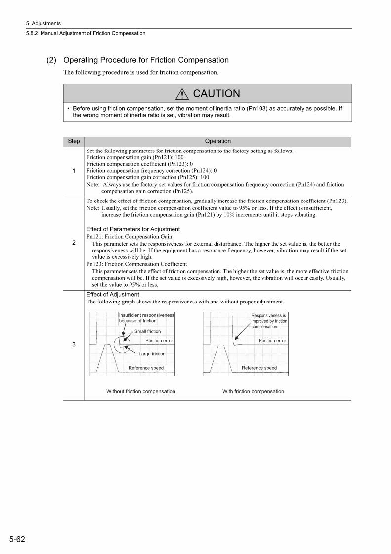
5 Adjustments
5.8.2 Manual Adjustment of Friction Compensation
5-62
(2) Operating Procedure for Friction Compensation
The following procedure is used for friction compensation.
CAUTION• Before using friction compensation, set the moment of inertia ratio (Pn103) as accurately as possible. If
the wrong moment of inertia ratio is set, vibration may result.
Step Operation
1
Set the following parameters for friction compensation to the factory setting as follows.Friction compensation gain (Pn121): 100Friction compensation coefficient (Pn123): 0Friction compensation frequency correction (Pn124): 0Friction compensation gain correction (Pn125): 100Note: Always use the factory-set values for friction compensation frequency correction (Pn124) and friction
compensation gain correction (Pn125).
2
To check the effect of friction compensation, gradually increase the friction compensation coefficient (Pn123).Note: Usually, set the friction compensation coefficient value to 95% or less. If the effect is insufficient,
increase the friction compensation gain (Pn121) by 10% increments until it stops vibrating.
Effect of Parameters for AdjustmentPn121: Friction Compensation Gain
This parameter sets the responsiveness for external disturbance. The higher the set value is, the better the responsiveness will be. If the equipment has a resonance frequency, however, vibration may result if the set value is excessively high.
Pn123: Friction Compensation CoefficientThis parameter sets the effect of friction compensation. The higher the set value is, the more effective friction compensation will be. If the set value is excessively high, however, the vibration will occur easily. Usually, set the value to 95% or less.
3
Effect of AdjustmentThe following graph shows the responsiveness with and without proper adjustment.
Position error
Reference speed
Position error
Reference speed
Small friction
Responsiveness is improved by friction compensation.
Large friction
Without friction compensation With friction compensation
Insufficient responsiveness because of friction

5.8 Additional Adjustment Function
5-63
5
Adj
ustm
ents
5.8.3 Current Control Mode Selection FunctionThis function reduces high-frequency noises while the servomotor is being stopped. This function is enabled by default and set to be effective under different application conditions. Set Pn009.1 = 1 to use this function.
This function can be used with the following SERVOPACKs.
5.8.4 Current Gain Level SettingThis function reduces noises by adjusting the parameter value for current control inside the SERVOPACK according to the speed loop gain (Pn100). The noise level can be reduced by reducing the current gain level (Pn13D) from its factory setting of 2000% (disabled). If the set value of Pn13D is decreased, the level of noise will be lowered, but the response characteristics of the SERVOPACK will also be degraded. Adjust the current gain level within the allowable range at which SERVOPACK response characteristics can be secured.
5.8.5 Speed Detection Method SelectionThe speed detection method selection can be used to smooth the speed of the servomotor during operation. To smooth the speed of the servomotor during operation, set Pn009 to n.1 to select speed detection 2.
Input Voltage SERVOPACK Model SGDV-
200 V 120A, 180A, 200A, 330A, 470A, 550A, 590A, 780A
400 V 3R5D, 5R4D, 8R4D, 120D, 170D, 210D, 260D, 280D, 370D
Parameter Meaning When Enabled Classification
Pn009n. 0 Selects the current control mode 1.
After restart Tuningn. 1[Factory setting]
Selects the current control mode 2 (low noise).
• If current control mode 2 is selected, the load ratio may increase while the servomotor is being stopped.
Pn13DCurrent Gain Level
ClassificationSetting Range Setting Unit Factory Setting When Enabled
100 to 2000 1% 2000 Immediately Tuning
• If this parameter is changed, the response characteristics of the speed loop will also change, and the SERVOPACK may require readjustment.
Speed Position
Parameter Meaning When Enabled Classification
Pn009n. 0[Factory setting]
Selects speed detection 1. After restart Tuning
n. 1 Selects speed detection 2.
• If the speed detection method is changed, the response characteristics of the speed loop will also change, and the SERVOPACK may require readjustment.

5 Adjustments
5.8.6 Backlash Compensation Function
5-64
5.8.6 Backlash Compensation Function
(1) Overview
When driving a machine with backlash, there will be a deviation between the travel distance in the position reference that is managed by the host controller and the travel distance of the actual machine. Use backlash compensation function to add the backlash compensation value to the position reference and use the result to drive the servomotor. This means that the travel distance of the actual machine will be the same as the travel distance in the host controller.
Note 1. This function is supported only for position control.2. Software version 0023 or higher is required to use this function. You can confirm the software version in Fn012.
For details, refer to 6.14 Software Version Display (Fn012).
(2) Related Parameter
Set the following parameter to use backlash compensation.
Backlash Compensation Direction
Set the direction in which to apply backlash compensation.
Backlash Compensation Value
Set the amount of backlash compensation to add to the position reference.The amount is set in increments of 0.1 reference unit. However, when the amount is converted to encoder pulses, it is rounded off at the decimal point.
Example: If Pn231 is set to 6,553.6 [reference unit] and the electronic gear ratio (Pn20E/Pn210) is set to 4/1, then the pulse equivalent is 6,553.6 × 4 = 26,214.4 [pulses].The backlash compensation value will be 26,214 encoder pulses.
Backlash (play due to mechanical precision)
Backlash compensation value
Reference forward rotational direction
Machine axis
Motor axis
Motor axis
Machine axis (e.g. table)
Travel distance by position reference
Travel distance by position reference
Parameter Function When Enabled Classification
Pn230
n. 0[Factory setting]
Compensates with a reference in the forward direc-tion.
After restart Setup
n. 1 Compensates with a reference in the reverse direc-tion.
Pn231
Backlash compensation valueClassification
Setting Range Setting Unit Factory Setting When Enabled
-500000 to 500000 0.1 reference unit 0 Immediately Setup
Position
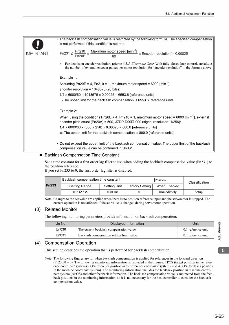
5.8 Additional Adjustment Function
5-65
5
Adj
ustm
ents
Backlash Compensation Time Constant
Set a time constant for a first order lag filter to use when adding the backlash compensation value (Pn231) to the position reference.If you set Pn233 to 0, the first order lag filter is disabled.
Note: Changes to the set value are applied when there is no position reference input and the servomotor is stopped. The current operation is not affected if the set value is changed during servomotor operation.
(3) Related Monitor
The following monitoring parameters provide information on backlash compensation.
(4) Compensation Operation
This section describes the operation that is performed for backlash compensation.
Note: The following figures are for when backlash compensation is applied for references in the forward direction (Pn230.0 = 0). The following monitoring information is provided in the figures: TPOS (target position in the refer-ence coordinate system), POS (reference position in the reference coordinate system), and APOS (feedback position in the machine coordinate system). The monitoring information includes the feedback position in machine coordi-nate system (APOS) and other feedback information. The backlash compensation value is subtracted from the feed-back positions in the monitoring information, so it is not necessary for the host controller to consider the backlash compensation value.
• The backlash compensation value is restricted by the following formula. The specified compensation is not performed if this condition is not met.
∗ For details on encoder resolution, refer to 8.3.5 Electronic Gear. With fully-closed loop control, substitute the number of external encoder pulses per motor revolution for “encoder resolution” in the formula above.
Example 1:
Assuming Pn20E = 4, Pn210 = 1, maximum motor speed = 6000 [min-1],
encoder resolution = 1048576 (20 bits):
1/4 × 6000/60 × 1048576 × 0.00025 = 6553.6 [reference units]
The upper limit for the backlash compensation is 6553.6 [reference units].
Example 2:
When using the conditions Pn20E = 4, Pn210 = 1, maximum motor speed = 6000 [min-1], external encoder pitch count (Pn20A) = 500, JZDP-D00-000 (signal resolution: 1/256):
1/4 × 6000/60 × (500 × 256) × 0.00025 = 800.0 [reference units]
The upper limit for the backlash compensation is 800.0 [reference units].
• Do not exceed the upper limit of the backlash compensation value. The upper limit of the backlash compensation value can be confirmed in Un031.
Pn231 ≤ Pn210Pn20E
Maximum motor speed [min-1]60
× × Encoder resolution × 0.00025
Pn233Backlash compensation time constant
ClassificationSetting Range Setting Unit Factory Setting When Enabled
0 to 65535 0.01 ms 0 Immediately Setup
Position
Un No. Displayed Information Unit
Un030 The current backlash compensation value 0.1 reference unit
Un031 Backlash compensation setting limit value 0.1 reference unit

5 Adjustments
5.8.6 Backlash Compensation Function
5-66
When Servo is ON
The backlash compensation value (Pn231) is added in the compensation direction when the servo is ON (i.e., the servomotor is powered) and a reference is input in the same direction as the backlash compensation direc-tion (Pn230.0). If there is a reference input in the direction opposite to the backlash compensation direction, the backlash compensation value is not added (i.e., backlash compensation is not performed).
The relationship between APOS and the servomotor shaft position is as follows:
• If a reference is input in the compensation direction: APOS = Motor shaft position - Pn231• If a reference is input in the direction opposite to the compensation direction: APOS = Motor shaft position
The following figure shows driving the servomotor in the forward direction from target position TPOS0 to TPOS1 and then to TPOS2, and then returning from TPOS2 to TPOS1 and then to TPOS0.
Backlash compensation is applied when moving from TPOS0 to TPOS1, but not when moving from TPOS2 to TPOS1.
CAUTION• The encoder output pulse will output the number of encoder pulses for which driving was actually per-
formed, including the backlash compensation value. If using the encoder output pulse for position feed-back at the host controller, must consider the backlash compensation value.
Machine axis
Motor axis
Machine axis
Pn231Travel distance Travel distance
Target positionTPOS0
Travel distance Travel distance
Target positionTPOS1
Target positionTPOS2
Machine axis
Motor axis
Machine axis
Pn231Travel distance Travel distance
Travel distance Travel distance
Motor axis
Motor axis
POS
APOS
Backlash (= Pn231)
POS
APOS
Backlash (= Pn231)
Servo ON
If a reference is input in the direction opposite to the compensation direction
If a reference is input in the compensation direction

5.8 Additional Adjustment Function
5-67
5
Adj
ustm
ents
When Servo is OFF
Backlash compensation is not applied when the servo is OFF (i.e., when the servomotor is not powered). Therefore, the reference position POS moves by only the backlash compensation value.
The relationship between APOS and the servomotor shaft position is as follows:
• When servo is OFF: APOS = Servomotor shaft position
The following figure shows what happens when the servo is turned OFF after driving the servomotor in the forward direction from target position TPOS0 to TPOS1. Backlash compensation is not applied when the servo is OFF (i.e., the SERVOPACK manages the position data so that APOS and POS are the same).
When There is Overtravel
When there is overtravel (i.e., when driving is prohibited due to an overtravel signal or software limit), the operation is the same as for 5.8.6 (4) When Servo is OFF, i.e., backlash compensation is not applied.
When Control is Changed
Backlash compensation is performed only for position control.Backlash compensation is not applied if changing from position control to any other type of control.Backlash compensation is applied in the same way as 5.8.6 (4) When Servo is ON if changing from any other type of control to position control.
When Safety Module Active Mode is Used
During an operation in active mode function, the operation is the same as for 5.8.6 (4) When Servo is OFF, i.e., backlash compensation is not applied.
Machine axis
Motor axis
Machine axis
Pn231Travel distance
Target positionTPOS0
Travel distance
Target positionTPOS1
Motor axis
POS
APOS
Backlash = Pn231
Servo OFF
Status with no backlash compensation POS = APOS

5 Adjustments
5.8.6 Backlash Compensation Function
5-68
(5) Monitor Functions (Un Monitoring)
(6) MECHATROLINK Monitor Information
This section describes the information that is set for the MECHATROLINK monitoring information (Monitor 1, Monitor 2, Monitor 3, and Monitor 4) and the backlash compensation operation.
Un No. Displayed Information Unit Specification
Un007 Input reference speed min-1 Indicates the input reference speed before backlash compensation.
Un008 Position error amount Reference unit Displays the position error with respect to the position reference after backlash compensation.
Un00C Input reference counter Reference unitDisplays the input reference counter before backlash compensation.
Un00D Feedback pulse counter Encoder pulseDisplays the pulse count of the actually driven motor encoder.
Un00E Fully-closed feedback pulse counter
External encoder resolution
Displays the pulse count of the actually driven external encoder.
Un013 Feedback pulse counter Reference unit Displays the pulse count of the actually driven encoder in reference units.
Monitor Code Designation Meaning Unit Remarks
0 POSReference position in the reference coordinate system (after the position reference filter)
Reference unit –
1 MPOS Reference position Reference unit –
2 PERR Position errorReference
unit –
3 APOS Feedback position in the machine coordinate system
Reference unit
Feedback position with the backlash compensation subtracted
4 LPOS Feedback latch position in the machine coordinate system
Reference unit
Feedback position with the backlash compensation subtracted
5 IPOSReference position in the reference coordinate system (before the position reference filter)
Reference unit –
6 TPOS Target position in the reference coor-dinate system
Reference unit –
E OMN1Option monitor 1 (selected with Pn824)
– –
F OMN2Option monitor 2 (selected with Pn825)
– –

5.8 Additional Adjustment Function
5-69
5
Adj
ustm
ents
Related Monitoring Diagrams
Parameters Monitor Information Output Unit Remarks
Pn824Pn825
0003H Position error (lower 32 bits)Reference
unit –
0004H Position error (upper 32 bits) Reference unit
–
000AH Encoder count (lower 32 bits) Reference unit Count value of the actually driven
motor encoder000BH Encoder count (upper 32 bits)
Reference unit
000CH FPG count (lower 32 bits)Reference
unit Count value of the actually driven external encoder
000DH FPG count (upper 32 bits) Reference unit
0017H Un007: Input reference speed min-1 Same as monitor display Un007
0018H Un008: Position error amount Reference unit Same as monitor display Un008
001CH Un00C: Input reference counterReference
unit Same as monitor display Un00C
001DH Un00D: Feedback pulse counter Encoder pulse
Same as monitor display Un00D
001EH Un00E: Fully-closed feedback pulse counter
External encoder
resolutionSame as monitor display Un00E
0080H Previous value of latched feedback position (LPOS)
Encoder pulse
Feedback position with the backlash compensation subtracted
Error counter
Error counter KpElectronic
gear
ENCSpeed conversation
Speed conversation
Load
External ENC
Feedforward
Speed/current
loop
[A][T][M]: Position error
[U][M]: Un007
Position reference
filter
[U][M]: Un00D
[U][M]: Un00E
[U][M]: Un00C
Position reference
[M]: TPOS
Electronic gear
Electronic gear
[M]: APOS
[M]: LPOS
Error counter[M]: PERR
[M]: IPOS
[M]: MPOS([M]: POS)
[M]: Previous value for LPOS
Latch signal
[A][T]: Position reference speed
Output signal processing
[A][O][T]: Positioning completed
[A][T]: Completion of position reference
[U][M]: Un008
[O][T]: Position near
[A][T]: Speed feedforward
[A][T]: Position amplifier error
[U]: Un013
<Legend symbols>[A]: Analog monitoring[U]: Monitor display (Un monitoring)[O]: Output signal[T]: Trace data object[M]: MECHATROLINK monitor information
[M]: PG count
[M]: FPG count
Backlash compensation function
Backlash compensation function
Electronic gear

5 Adjustments
5.9.1 Feedforward Reference
5-70
5.9 Compatible Adjustment FunctionThe Σ-V series SERVOPACKs have adjustment functions as explained in sections 5.1 to 5.8 to make machine adjustments. This section explains compatible functions provided by earlier models, such as the Σ-III Series SERVOPACK.
5.9.1 Feedforward ReferenceThis function applies feedforward compensation to position control and shortens positioning time.
Note: Too high value may cause the machine to vibrate. For ordinary machines, set 80% or less in this parameter.
Pn109Feedforward Gain
ClassificationSetting Range Setting Unit Factory Setting When Enabled
0 to 100 1% 0 Immediately Tuning
Pn10AFeedforward Filter Time Constant
ClassificationSetting Range Setting Unit Factory Setting When Enabled
0 to 6400 0.01 ms 0 Immediately Tuning
+ + + -
Pn109Pn10A
Positionreference
Feedback pulse
Position loop gain (Kp)
Feedforward GainDifferential Feedforward Filter Time Constant
Position
Position

5.9 Compatible Adjustment Function
5-71
5
Adj
ustm
ents
5.9.2 Mode Switch (P/PI Switching)The mode switch automatically switches between proportional and PI control. Set the switching condition with Pn10B.0 and set the level of detection points with Pn10C, Pn10D, Pn10E, and Pn10F.
Overshooting caused by acceleration and deceleration can be suppressed and the settling time can be reduced by setting the switching condition and detection points.
(1) Related Parameters
Select the switching condition of the mode switch with Pn10B.0.
Parameters to Set the Level of Detection Points
Actual servomotor operation
Reference
Settling time
Without Mode Switch With Mode Switch
Overshoot Motor speed
Time
Motor speed
Time Overshoot Settling time
Parameter Mode Switch Selection
Parameter Containing Detection
Point Setting
When Enabled
Classifi-cation
Pn10B
n.0[Factory setting]
Uses an internal torque reference level for the switching conditions. Pn10C
Immedi-ately Setup
n.1Uses a speed reference level for the switching condi-tions. Pn10D
n.2 Uses an acceleration level for the switching condi-tions.
Pn10E
n.3 Uses a position error level for the switching condi-tions. Pn10F
n.4 Does not use mode switch function. −
Pn10C
Mode Switch (Torque Reference)Classification
Setting Range Setting Unit Factory Setting When Enabled
0 to 800 1% 200 Immediately Tuning
Pn10D
Mode Switch (Speed Reference)Classification
Setting Range Setting Unit Factory Setting When Enabled
0 to 10000 1 min-1 0 Immediately Tuning
Pn10E
Mode Switch (Acceleration)Classification
Setting Range Setting Unit Factory Setting When Enabled
0 to 30000 1 min-1/s 0 Immediately Tuning
Pn10F
Mode Switch (Position Error)Classification
Setting Range Setting Unit Factory Setting When Enabled
0 to 10000 1 reference unit 0 Immediately Tuning
Speed Position
Speed Position
Speed Position
Position

5 Adjustments
5.9.2 Mode Switch (P/PI Switching)
5-72
(2) Operating Examples for Different Switching Conditions
Using the Torque Reference [Factory Setting]
With this setting, the speed loop is switched to P control when the value of torque reference input exceeds the torque set in Pn10C. The factory setting for the torque reference detection point is 200% of the rated torque.
Using the Speed Reference
With this setting, the speed loop is switched to P control when the value of speed reference input exceeds the speed set in Pn10D.
Using Acceleration
With this setting, the speed loop is switched to P control when the speed reference exceeds the acceleration set in Pn10E.
Using the Position Error
With this setting, the speed loop is switched to P control when the position error exceeds the value set in Pn10F.
This setting is effective with position control only.
Motor speedSpeed referenceSpeed
+Pn10CTorque Reference
-Pn10C
Torque reference
PI Control PI Control
0
PI PP
Time
Speed referenceSpeed Motor speed
TimeP Control PI Control
Pn10D
PI
Motor speedSpeed referenceSpeed
Motor acceleration+Pn10E
Acceleration
-Pn10E
PI Control PI Control
0
PI PP
Time
Position error
Speed referenceSpeed
Motor speed
Time
P Control PI ControlPn10F
PI

5.9 Compatible Adjustment Function
5-73
5
Adj
ustm
ents
5.9.3 Torque Reference FilterAs shown in the following diagram, the torque reference filter contains first order lag filter and notch filters arrayed in series, and each filter operates independently. The notch filters can be enabled and disabled with the Pn408.
(1) Torque Reference Filter
If you suspect that machine vibration is being caused by the servo drive, try adjusting the filter time constants with Pn401. This may stop the vibration. The lower the value, the better the response will be, but there may be
a limit that depends on the machine conditions.
Torque Reference Filter Setting Guide
Speed Loop Gain and Torque Reference Filter Time Constant
Adjusted value for stable control: Pn401 [ms] ≤ 1000/ (2π × Pn100 [Hz] × 4)Critical gains: Pn401 [ms] < 1000/ (2π × Pn100 [Hz] × 1)
∗ The filter is disabled if 5000 is set.
Torque reference before filtering
Torque RelatedFunction SwitchPn408
Notch filter Notch filter First order lag filter
Torque reference after filtering
Second order lag filter
2nd Notch Filter (Pn40C, Pn40D, and Pn40E)
1st Notch Filter (Pn409, Pn40A,and Pn40B)
* The 2nd torque reference filter is enabled when Pn40F is set to a value less than
5000 and disabled when Pn40F is set to 5000 (factory setting).
*
Torque Reference
Filter (Pn401)
2nd Torque Reference Filter(Pn40F, Pn410)
Pn401Torque Reference Filter Time Constant
ClassificationSetting Range Setting Unit Factory Setting When Enabled
0 to 65535 0.01 ms 100 Immediately Tuning
Speed Position Torque
Pn40F
2nd Step 2nd Torque Reference Filter Frequency
Classification
Setting Range Setting Unit Factory Setting When Enabled
100 to 5000 1 Hz 5000* Immediately Tuning
Pn410
2nd Step 2nd Torque Reference Filter Q Value
Classification
Setting Range Setting Unit Factory Setting When Enabled
50 to 100 0.01 50 Immediately Tuning
Speed Position Torque
Speed Position Torque

5 Adjustments
5.9.3 Torque Reference Filter
5-74
(2) Notch Filter
The notch filter can eliminate specific frequency elements generated by the vibration of sources such as reso-nance of the shaft of a ball screw. The notch filter puts a notch in the gain curve at the specific vibration fre-quency. The frequency characteristics near the notch can be reduced or removed with this filter. A higher Q value produces a sharper notch and phase delay.
The notch filter can be enabled or disabled with Pn408.
Set the machine's vibration frequency as a parameter of the notch filter.
Q value = 0.7 Q value = 1.0
Notch Filter
Frequency (Hz)
-300
-200
-100
0
100
2 10 10 3 10 4
Gain(db)
-300
-200
-100
0
100
2 10 10 3 10 4
Notch Filter
Frequency (Hz)
Gain(db)
2 10 10 3 10 4 -400
-300
-200
-100
0 Notch Filter
Frequency (Hz)
Phase(deg)
2 10 10 3 10 4 -400
-300
-200
-100
0 Notch Filter
Frequency (Hz)
Phase(deg)
Parameter Meaning When Enabled Classification
Pn408
n.0 [Factory setting] Disables 1st notch filter.
Immediately Setupn.1 Enables 1st notch filter.
n.0[Factory setting] Disables 2nd notch filter.
n.1 Enables 2nd notch filter.
Pn4091st Notch Filter Frequency
ClassificationSetting Range Setting Unit Factory Setting When Enabled
50 to 5000 1 Hz 5000 Immediately Tuning
Pn40A1st Notch Filter Q Value
ClassificationSetting Range Setting Unit Factory Setting When Enabled
50 to 1000 0.01 70 Immediately Tuning
Pn40B1st Notch Filter Depth
ClassificationSetting Range Setting Unit Factory Setting When Enabled
0 to 1000 0.001 0 Immediately Tuning
Pn40C2nd Notch Filter Frequency
ClassificationSetting Range Setting Unit Factory Setting When Enabled
50 to 5000 1 Hz 5000 Immediately Tuning
Speed Position Torque
Speed Position Torque
Speed Position Torque
Speed Position Torque

5.9 Compatible Adjustment Function
5-75
5
Adj
ustm
ents
5.9.4 Position IntegralThe position integral is the integral function of the position loop. It is used for the electronic cams and elec-tronic shafts when using the SERVOPACK with YASKAWA MP900/2000 Machine Controllers.
Pn40D2nd Notch Filter Q Value
ClassificationSetting Range Setting Unit Factory Setting When Enabled
50 to 1000 0.01 70 Immediately Tuning
Pn40E2nd Notch Filter Depth
ClassificationSetting Range Setting Unit Factory Setting When Enabled
0 to 1000 0.001 0 Immediately Tuning
• Sufficient precautions must be taken when setting the notch filter frequencies. Do not set the notch filter frequencies (Pn409 or Pn40C) that is close to the speed loop’s response frequency. Set the frequencies at least four times higher than the speed loop’s response frequency. Setting the notch filter frequency too close to the response frequency may cause vibration and damage the machine.
• Change the notch filter frequencies (Pn409 or Pn40C) only when the servomotor is stopped. Vibration may occur if the notch filter frequency is changed when the servo-motor is rotating.
(cont’d)
Speed Position Torque
Speed Position Torque
Pn11FPosition Integral Time Constant
ClassificationSetting Range Setting Unit Factory Setting When Enabled
0 to 50000 0.1 ms 0 Immediately Tuning
Position

6-1
6
Util
ity F
unct
ions
(F
n
)
6Utility Functions (Fn)
6.1 List of Utility Functions . . . . . . . . . . . . . . . . . . . . . . . . . . . . . . . . . . . . . . .6-2
6.2 Alarm History Display (Fn000) . . . . . . . . . . . . . . . . . . . . . . . . . . . . . . . . .6-3
6.3 JOG Operation (Fn002) . . . . . . . . . . . . . . . . . . . . . . . . . . . . . . . . . . . . . .6-4
6.4 Origin Search (Fn003) . . . . . . . . . . . . . . . . . . . . . . . . . . . . . . . . . . . . . . .6-6
6.5 Program JOG Operation (Fn004) . . . . . . . . . . . . . . . . . . . . . . . . . . . . . . .6-8
6.6 Initializing Parameter Settings (Fn005) . . . . . . . . . . . . . . . . . . . . . . . . . . 6-12
6.7 Clearing Alarm History (Fn006) . . . . . . . . . . . . . . . . . . . . . . . . . . . . . . . 6-13
6.8 Offset Adjustment of Analog Monitor Output (Fn00C) . . . . . . . . . . . . . . 6-14
6.9 Gain Adjustment of Analog Monitor Output (Fn00D) . . . . . . . . . . . . . . . 6-16
6.10 Automatic Offset-Signal Adjustment of the Motor Current Detection Signal (Fn00E) . . . . . . . . . . . . . . . . . . . . . . . . . . . . . . . . . . . 6-18
6.11 Manual Offset-Signal Adjustment of the Motor Current Detection Signal (Fn00F) . . . . . . . . . . . . . . . . . . . . . . . . . . . . . . . . . . . 6-19
6.12 Write Prohibited Setting (Fn010) . . . . . . . . . . . . . . . . . . . . . . . . . . . . . . 6-21
6.13 Servomotor Model Display (Fn011) . . . . . . . . . . . . . . . . . . . . . . . . . . .6-23
6.14 Software Version Display (Fn012) . . . . . . . . . . . . . . . . . . . . . . . . . . . .6-24
6.15 Resetting Configuration Errors in Option Modules (Fn014) . . . . . . . . . 6-25
6.16 Vibration Detection Level Initialization (Fn01B) . . . . . . . . . . . . . . . . . . 6-26
6.17 Display of SERVOPACK and Servomotor ID (Fn01E) . . . . . . . . . . . . . 6-28
6.18 Display of Servomotor ID in Feedback Option Module (Fn01F) . . . . . .6-30
6.19 Origin Setting (Fn020) . . . . . . . . . . . . . . . . . . . . . . . . . . . . . . . . . . . . . .6-31
6.20 Software Reset (Fn030) . . . . . . . . . . . . . . . . . . . . . . . . . . . . . . . . . . . . 6-32
6.21 EasyFFT (Fn206) . . . . . . . . . . . . . . . . . . . . . . . . . . . . . . . . . . . . . . . . . 6-33
6.22 Online Vibration Monitor (Fn207) . . . . . . . . . . . . . . . . . . . . . . . . . . . . . 6-37

6 Utility Functions (Fn)
6-2
6.1 List of Utility FunctionsUtility functions are used to execute the functions related to servomotor operation and adjustment.Each utility function has a number starting with Fn.
The following table lists the utility functions and reference section.
Note: Execute the utility function with either a digital operator or SigmaWin+. If they are used together, "no_oP" or "NO-OP" will be displayed when the utility function is executed.
Function No.
FunctionReference
Section
Fn000 Alarm history display 6.2
Fn002 JOG operation 6.3
Fn003 Origin search 6.4
Fn004 Program JOG operation 6.5
Fn005 Initializing parameter settings 6.6
Fn006 Clearing alarm history 6.7
Fn008 Absolute encoder multiturn reset and encoder alarm reset 4.7.4
Fn00C Offset adjustment of analog monitor output 6.8
Fn00D Gain adjustment of analog monitor output 6.9
Fn00E Automatic offset-signal adjustment of the motor current detection signal 6.10
Fn00F Manual offset-signal adjustment of the motor current detection signal 6.11
Fn010 Write prohibited setting 6.12
Fn011 Servomotor model display 6.13
Fn012 Software version display 6.14
Fn013 Multiturn limit value setting change when a multiturn limit disagreement alarm occurs 4.7.7
Fn014 Resetting configuration error in option modules 6.15
Fn01B Vibration detection level initialization 6.16
Fn01E Display of SERVOPACK and servomotor ID 6.17
Fn01F Display of servomotor ID in feedback option module 6.18
Fn020 Origin setting 6.19
Fn030 Software reset 6.20
Fn200 Tuning-less levels setting 5.2.2
Fn201 Advanced autotuning 5.3.2
Fn202 Advanced autotuning by reference 5.4.2
Fn203 One-parameter tuning 5.5.2
Fn204 Anti-resonance control adjustment function 5.6.2
Fn205 Vibration suppression function 5.7.2
Fn206 EasyFFT 6.21
Fn207 Online vibration monitor 6.22

6.2 Alarm History Display (Fn000)
6-3
6
Util
ity F
unct
ions
(F
n
)
6.2 Alarm History Display (Fn000)This function displays the last ten alarms that have occurred in the SERVOPACK.
The latest ten alarm numbers and time stamps* can be checked.
∗ Time Stamps
A function that measures the ON times of the control power supply and main circuit power supply in 100-ms units and displays the total operating time when an alarm occurs. The time stamp operates around the clock for approximately 13 years.
<Example of Time Stamps>If 36000 is displayed,3600000 [ms] = 3600 [s] = 60 [min] = 1 [h] Therefore, the total number of operating hours is 1 hour.
(1) Preparation
There are no tasks that must be performed before displaying the alarm history.
(2) Operating Procedure
Use the following procedure.
<NOTE>• If the same alarm occurs after more than one hour, the alarm will be saved. If it occurs in less than one hour, it
will not be saved.• If no alarm has occurred, “:---” will be displayed on the digital operator.• Delete the alarm history using the parameter Fn006. The alarm history is not cleared on alarm reset or when the
SERVOPACK main circuit power is turned OFF.
Step Display after Operation Keys Operation
1
Press the Key to view the main menu for the utility function.
Use the or Key to move through the list and select Fn000.
2 Press the Key. The display changes to the Fn000 execution display.
3 Press the or Key to scroll through the alarm history. The alarm history can be viewed.
4Press the Key.The display returns to the main menu of the utility function.
B B − F U N C T I O N −F n 2 0 7 : V − M o n i t o rF n 0 0 0 : A l m H i s t o r yF n 0 0 2 : J O GF n 0 0 3 : Z − S e a r c h
A . D 0 0 − A L A R M −0 : D 0 0 0 0 0 0 1 2 0 7 1 9 61 : 7 2 0 0 0 0 0 0 0 3 2 6 5 12 : 5 1 1 0 0 0 0 0 0 0 9 0 4 33 : − − −
A . D 0 0 − A L A R M −1 : 7 2 0 0 0 0 0 0 0 3 2 6 5 12 : 5 1 1 0 0 0 0 0 0 0 9 0 4 33 : − − −4 : − − −
Time stampAlarm no.
Alarm history no. 0: Latest 9: Oldest
B B − F U N C T I O N −F n 2 0 7 : V − M o n i t o rF n 0 0 0 : A l m H i s t o r yF n 0 0 2 : J O GF n 0 0 3 : Z − S e a r c h

6 Utility Functions (Fn)
6-4
6.3 JOG Operation (Fn002)JOG operation is used to check the operation of the servomotor under speed control without connecting the SERVOPACK to the host controller.
(1) Preparation
The following conditions must be met to perform a jog operation.
• The write prohibited setting (Fn010) must be set to Write permitted (P.0000).• The main circuit power supply must be ON.• All alarms must be cleared.• The hardwire baseblock (HWBB) must be disabled.• The servomotor power must be OFF.• The JOG speed must be set considering the operating range of the machine.
Set the jog speed in Pn304.
∗ When using an SGMCS direct drive motor, the setting unit will be automatically changed to 0.1 min-1.
(2) Operating Procedure
Use the following procedure. The following example is for when the rotating direction of the servomotor is set as Pn000.0 = 0 (Sets CCW as forward direction).
CAUTION• While the SERVOPACK is in JOG operation, the overtravel function will be disabled. Consider the operat-
ing range of the machine when performing JOG operation for the SERVOPACK.
Pn304
Jog Speed Classification
Setting Range Setting Unit Factory Setting When Enabled
0 to 10000 1 min-1* 500 Immediately Setup
Speed Position Torque
Step Display after Operation Keys Operation
1
Press the Key to view the main menu for the utility function.
Use the or Key to move through the list and select Fn002.
2 Press the Key. The display changes to the Fn002 execution display.
3 Press the Key to move the cursor to the setting side of Pn304 (JOG Speed).
4Press the or Key and the or Key to set the JOG speed (Pn304) to 1000
min-1.
5Press the Key.The setting value is entered, and the cursor moves to the parameter number side (the left side).
B B − F U N C T I O N −F n 0 0 0 : A l m H i s t o r yF n 0 0 2 : J O GF n 0 0 3 : Z − S e a r c hF n 0 0 4 : P r o g r a m J O G
B B − J O G −P n 3 0 4 = 0 0 5 0 0U n 0 0 0 = 0 0 0 0 0 0U n 0 0 2 = 0 0 0 0 0 0U n 0 0 D = 0 0 0 0 0 0 0 0 0 0 0
B B − J O G −P n 3 0 4 = 0 0 5 0 0U n 0 0 0 = 0 0 0 0 0 0U n 0 0 2 = 0 0 0 0 0 0U n 0 0 D = 0 0 0 0 0 0 0 0 0 0 0
B B − J O G −P n 3 0 4 = 0 1 0 0 0U n 0 0 0 = 0 0 0 0 0 0U n 0 0 2 = 0 0 0 0 0 0U n 0 0 D = 0 0 0 0 0 0 0 0 0 0 0
B B − J O G −P n 3 0 4 = 0 1 0 0 0U n 0 0 0 = 0 0 0 0 0 0U n 0 0 2 = 0 0 0 0 0 0U n 0 0 D = 0 0 0 0 0 0 0 0 0 0 0

6.3 JOG Operation (Fn002)
6-5
6
Util
ity F
unct
ions
(F
n
)
6Press the Key.The status display changes from "BB" to "RUN", and the servomotor power turns ON.
7
The servomotor will rotate at the present speed set in
Pn304 while the Key (for forward rotation) or Key (for reverse rotation) is pressed.
8
After having confirmed the correct motion of servo-
motor, press the Key.The status display changes from "RUN" to "BB", and the servomotor power turns OFF.
9Press the Key.The display returns to the main menu of the utility function.
10 To enable the setting, turn the power supply to the SERVOPACK OFF and ON again.
(cont’d)
Step Display after Operation Keys Operation
R U N − J O G −P n 3 0 4 = 0 1 0 0 0U n 0 0 0 = 0 0 0 0 0 0U n 0 0 2 = 0 0 0 0 0 0U n 0 0 D = 0 0 0 0 0 0 0 0 0 0 0
R U N − J O G −P n 3 0 4 = 0 1 0 0 0U n 0 0 0 = 0 0 0 0 0 0U n 0 0 2 = 0 0 0 0 0 0U n 0 0 D = 0 0 0 0 0 0 0 0 0 0 0
Forward
Reverse
B B − J O G −P n 3 0 4 = 0 1 0 0 0U n 0 0 0 = 0 0 0 0 0 0U n 0 0 2 = 0 0 0 0 0 0U n 0 0 D = 0 0 0 0 0 0 0 0 0 0 0
B B − F U N C T I O N −F n 0 0 0 : A l m H i s t o r yF n 0 0 2 : J O GF n 0 0 3 : Z − S e a r c hF n 0 0 4 : P r o g r a m J O G

6 Utility Functions (Fn)
6-6
6.4 Origin Search (Fn003)The origin search is designed to position the origin pulse position of the incremental encoder (phase C) and to clamp at the position.
This function is used when the motor shaft needs to be aligned to the machine.Motor speed at the time of execution: 60 min-1
(For SGMCS direct drive motors, the speed at the time of execution is 6 min-1.)
(1) Preparation
The following conditions must be met to perform the origin search.
• The write prohibited setting (Fn010) must be set to Write permitted (P.0000).• The main circuit power supply must be ON.• All alarms must be cleared.• The hardwire baseblock (HWBB) must be disabled.• The servomotor power must be OFF.
CAUTION• Perform origin searches without connecting the coupling.
The forward run prohibited (P-OT) and reverse run prohibited (N-OT) signals are not effective in origin search mode.
For aligning the motorshaft to the machine
Servomotor Machine

6.4 Origin Search (Fn003)
6-7
6
Util
ity F
unct
ions
(F
n
)
(2) Operating Procedure
Use the following procedure.
Step Display after Operation Keys Operation
1
Press the Key to view the main menu for the util-ity function.
Use the or Key to move through the list and select Fn003.
2 Press the Key. The display changes to the Fn003 execution display.
3
Press the Key.The status display changes from "BB" to "RUN", and the servomotor power turns ON.Note: If the servomotor is already at the zero position,
"-Complete-" is displayed.
4
Pressing the Key will rotate the servomotor in the
forward direction. Pressing the Key will rotate the servomotor in the reverse direction. The rotation direc-tion of the servomotor changes according to the setting of Pn000.0 as shown in the following table.
Note: Direction when viewed from the load of the ser-vomotor.
Press the or Key until the servomotor stops. If the origin search completed normally, "-Complete-" is displayed on the right top on the screen.
5
When the origin search is completed, press the Key.The status display changes from "RUN" to "BB", and the servomotor turns OFF. The display "-Complete-" changes to "-Z-Search-."
6Press the Key.The display returns to the main menu of the utility function.
7 To enable the setting, turn the power supply to the SERVOPACK OFF and ON again.
B B − F U N C T I O N −F n 0 0 2 : J O GF n 0 0 3 : Z − S e a r c hF n 0 0 4 : P r o g r a m J O GF n 0 0 5 : P r m I n i t
B B − Z − S e a r c h −U n 0 0 0 = 0 0 0 0 0 0U n 0 0 2 = 0 0 0 0 0 0U n 0 0 3 = 0 0 0 0 0 0 0 0 7 7 4U n 0 0 D = 0 0 0 0 0 0 0 0 0 0 0
R U N − Z − S e a r c h −U n 0 0 0 = 0 0 0 0 0 0U n 0 0 2 = 0 0 0 0 0 0U n 0 0 3 = 0 0 0 0 0 0 0 0 7 7 4U n 0 0 D = 0 0 0 0 0 0 0 0 0 0 0
R U N − C o m p l e t e −U n 0 0 0 = 0 0 0 0 0 0U n 0 0 2 = 0 0 0 0 0 0U n 0 0 3 = 0 0 0 0 0 0 0 0 0 0 0U n 0 0 D = 0 0 0 0 0 0 0 1 D 5 8
Parameter key key
Pn000n.0 CCW CW
n.1 CW CCW
B B − Z − S e a r c h −U n 0 0 0 = 0 0 0 0 0 0U n 0 0 2 = 0 0 0 0 0 0U n 0 0 3 = 0 0 0 0 0 0 0 0 0 0 0U n 0 0 D = 0 0 0 0 0 0 0 1 D 5 8
B B − F U N C T I O N −F n 0 0 2 : J O GF n 0 0 3 : Z − S e a r c hF n 0 0 4 : P r o g r a m J O GF n 0 0 5 : P r m I n i t

6 Utility Functions (Fn)
6-8
6.5 Program JOG Operation (Fn004)The program JOG operation is a utility function, that allows continuous operation determined by the preset operation pattern, movement distance, movement speed, acceleration/deceleration time, waiting time, and number of times of movement.This function can be used to move the servomotor without it having to be connected to a host controller for the machine as a trial operation in JOG operation mode. Program JOG operation can be used to confirm the oper-ation and for simple positioning operations.
(1) Preparation
The following conditions must be met to perform the program JOG operation.
• The write prohibited setting (Fn010) must be set to Write permitted (P.0000).• The main circuit power supply must be ON.• All alarms must be cleared.• The hardwire baseblock (HWBB) must be disabled.• The servomotor power must be OFF.• The travel distance and speed must be set correctly considering the machine operation range and safe opera-
tion speed.• There must be no overtravel.
(2) Additional Information
• The functions that are applicable for position control, such as position reference filter, can be used.• The overtravel function is enabled in this function.
(3) Program JOG Operation Patterns
A program JOG operation pattern is shown here. This program JOG operation pattern shows when the rotating direction of the servomotor is set as Pn000.0 = 0 (Sets CCW as forward direction).
Note: When Pn536 (number of times of program JOG movement) is set to 0, infinite time operation is enabled. To stop infinite time operation, press the JOG/SVON Key to turn OFF the servomotor power.
Pn530.0 = 0
(Waiting time Pn535 → Forward movement Pn531) × Number of movements Pn536
Speed Diagram
Servomotor Run Status
(Stop) (Forward) (Stop) (Forward) (Stop) (Forward)
Movementspeed
Pn533
Key.Press the
Waiting timePn535
Accel/Deceltime Waiting time
Pn534 Pn535Waiting time
Pn535
Number of times of movement Pn536
At zero speed
Movementdistance
Pn531Movementdistance
Pn531Movementdistance
Pn531

6.5 Program JOG Operation (Fn004)
6-9
6
Util
ity F
unct
ions
(F
n
)
Note: When Pn536 (Number of Times of Program JOG Movement) is set to 0, infinite time operation is enabled. To stop infinite time operation, press the JOG/SVON Key to turn the servomotor power OFF.
Note: When3 Pn530.0 is set to 2, infinite time operation is disabled.
Note: When Pn530.0 is set to 3, infinite time operation is disabled.
Pn530.0 = 1
(Waiting time Pn535 → Reverse movement Pn531) × Number of movements Pn536
Speed Diagram
Servomotor Run Status
(Stop) (Reverse) (Stop) (Reverse) (Stop) (Reverse)
MovementspeedPn533
Waiting timePn535
Accel/Decel timeWaiting timePn534
Pn535Waiting time
Pn535
Number of movements Pn536
At zero speed
Movementdistance
Pn531Movementdistance
Pn531Movementdistance
Pn531
Key.Press the
Pn530.0 = 2
(Waiting time Pn535 → Forward movement Pn531) × Number of movements Pn536 (Waiting time Pn535 → Reverse movement Pn531) × Number of movements Pn536
Speed Diagram
Servomotor Run Status
(Stop) (Forward) (Stop) (Forward) (Stop) (Reverse) (Stop) (Reverse)
Pn535Pn534
Pn535
Movementspeed Movement
distancePn533
Pn531
Waiting time
Pn535
Accel/Deceltime
Pn534
Accel/Decel time
Waiting time
Pn535
Waiting time
Waiting time
MovementspeedPn533
Number of movements Pn536 Number of movements Pn536
At zerospeed
Movementdistance
Pn531
Movementdistance
Pn531Movementdistance
Pn531
Key.Press the
Pn530.0 = 3
(Waiting time Pn535 → Reverse movement Pn531) × Number of movements Pn536 (Waiting time Pn535 → Forward movement Pn531) × Number of movements Pn536
Speed Diagram
Servomotor Run Status
(Stop) (Reverse) (Stop) (Reverse) (Stop) (Forward) (Stop) (Forward)
Movement speedPn533
Accel/Decel time
Pn534
Accel/Decel time
Pn534
Waiting time
Pn535
Waiting time
Pn535
MovementspeedPn533
Waiting time
Pn535
Waiting time
Pn535
Number of movements Pn536 Number of movements Pn536
At zerospeed
Pn531Movementdistance
Pn531Movementdistance
Movementdistance
Pn531Movementdistance
Pn531
Key.Press the

6 Utility Functions (Fn)
6-10
Note: When Pn536 (number of times of program JOG movement) is set to 0, infinite time operation is enabled. To stop infinite time operation, press the JOG/SVON Key to turn OFF the servomotor power.
Note: When Pn536 (number of times of program JOG movement) is set to 0, infinite time operation is enabled. To stop infinite time operation, press the JOG/SVON Key to turn the servomotor power OFF.
(4) Related ParametersThe following parameters set the program JOG operation pattern. Do not change the settings while the pro-gram JOG operation is being executed.
Pn530.0 = 4
(Waiting time Pn535 → Forward movement Pn531 → Waiting time Pn535 → Reserve movement Pn531) × Number of movements Pn536
Speed Diagram
Servomotor Run Status
(Stop) (Forward) (Stop) (Reverse) (Stop)
Pn530.0 = 5
(Waiting time Pn535 → Reverse movement Pn531 → Waiting time Pn535 → Forward movement Pn531) × Number of movements Pn536
Speed Diagram
Servomotor Run Status
(Stop) (Reverse) (Stop) (Forward) (Stop)
Movement speedPn533
Accel/Decel timePn534
Pn533
Waiting timePn535
Waiting timePn535
Number of movements Pn536
Movementspeed
At zerospeed
Movementdistance
Pn531
Movementdistance
Pn531 Key.Press the
Movement speedPn533
Accel/Decel timePn534Waiting time
Pn535Waiting time
Pn535
Number of movements Pn536
At zerospeed
Movementdistance
Pn531
Movementdistance
Pn531
Key.Press the Movement speed
Pn533
Pn530Program JOG Operation Related Switch
ClassificationSetting Range Setting Unit Factory Setting When Enabled
0000 to 0005 − 0000 Immediately Setup
Pn531Program JOG Movement Distance
ClassificationSetting Range Setting Unit Factory Setting When Enabled
1 to 1073741824 1 reference unit 32768 Immediately Setup
Pn533Program JOG Movement Speed
ClassificationSetting Range Setting Unit Factory Setting When Enabled
1 to 10000 1 min-1* 500 Immediately Setup
Speed Position Torque
Speed Position Torque
Speed Position Torque

6.5 Program JOG Operation (Fn004)
6-11
6
Util
ity F
unct
ions
(F
n
)
∗ When using an SGMCS direct drive motor, the setting unit will be automatically changed to 0.1 min-1.
(5) Operating Procedure
Use the following procedure to perform the program JOG operation after setting a program JOG operation pattern.
∗ The settings can be changed for a parameter.
Pn534Program JOG Acceleration/Deceleration Time
ClassificationSetting Range Setting Unit Factory Setting When Enabled
2 to 10000 1 ms 100 Immediately Setup
Pn535Program JOG Waiting Time
ClassificationSetting Range Setting Unit Factory Setting When Enabled
0 to 10000 1 ms 100 Immediately Setup
Pn536Number of Times of Program JOG Movement
ClassificationSetting Range Setting Unit Factory Setting When Enabled
0 to 1000 1 time 1 Immediately Setup
(cont’d)
Speed Position Torque
Speed Position Torque
Speed Position Torque
Step Display after Operation Keys Operation
1
Press the Key to view the main menu for the utility function.
Use the or Key to move through the list and select Fn004.
2 Press the Key. The display changes to the Fn004 execution display.
3*
Confirm that the parameters have been set.
Press the Key to view Pn530.
Press the Key to view the parameters in the fol-lowing order: Pn530 → Pn531 → Pn533 → Pn534 → Pn535 → Pn536.
4Press the Key.The status display changes from "BB" to "RUN", and the servomotor power turns ON.
5
Press the (forward movement start) or (reverse movement start) Key according to the first movement direction of the preset operation pattern. The servomotor starts moving after the preset waiting time in Pn535.Note: Pressing the Key again changes the status to "BB" (baseblocked status) and stops movement even during operation.
6
When the set program JOG operation movement is completed, "END" is displayed for one second, and then "RUN" is displayed.
Press the Key. The servomotor becomes base-blocked status. The display returns to the main menu of the utility function.
7 To enable the setting, turn the power supply to the SERVOPACK OFF and ON again.
B B − F U N C T I O N −F n 0 0 3 : Z − S e a r c hF n 0 0 4 : P r o g r a m J O GF n 0 0 5 : P r m I n i tF n 0 0 6 : A l m H i s t C l r
B B − P R G J O G − P n 5 3 1 = 0 0 0 3 2 7 6 8 P n 5 3 3 = 0 0 5 0 0 P n 5 3 4 = 0 0 1 0 0 P n 5 3 6 = 0 0 0 1 0
B B − P R G J O G − P n 5 3 1 = 0 0 0 3 2 7 6 8 P n 5 3 3 = 0 0 5 0 0 P n 5 3 4 = 0 0 1 0 0 P n 5 3 6 = 0 0 0 1 0
R U N − P R G J O G −P n 5 3 1 = 0 0 0 3 2 7 6 8P n 5 3 3 = 0 0 5 0 0P n 5 3 4 = 0 0 1 0 0P n 5 3 6 = 0 0 0 1 0
R U N − P R G J O G −P n 5 3 1 = 0 0 0 3 2 7 6 8P n 5 3 3 = 0 0 5 0 0P n 5 3 4 = 0 0 1 0 0P n 5 3 6 = 0 0 0 1 0
R U N − P R G J O G −P n 5 3 1 = 0 0 0 3 2 7 6 8P n 5 3 3 = 0 0 5 0 0P n 5 3 4 = 0 0 1 0 0P n 5 3 6 = 0 0 0 1 0

6 Utility Functions (Fn)
6-12
6.6 Initializing Parameter Settings (Fn005)
This function is used when returning to the factory settings after changing parameter settings.
Note: Any value adjusted with Fn00C, Fn00D, Fn00E, and Fn00F cannot be initialized by Fn005.
(1) Preparation
The following conditions must be met to initialize the parameter values.
• The write prohibited setting (Fn010) must be set to Write permitted (P.0000).• The servomotor power must be OFF.
(2) Operating Procedure
Use the following procedure.
• Be sure to initialize the parameter settings while the servomotor power is OFF.• After initialization, turn OFF the power supply and then turn ON again to validate the
settings.
Step Display after Operation Keys Operation
1
Press the Key to view the main menu for the utility function.
Use the or Key to move through the list and select Fn005.
2 Press the Key. The display changes to the Fn005 execution display.
3
Press the Key to initialize parameters.During initialization, "Parameter Init" is flashing in the display. After the initialization is completed, "Parameter Init" stops flashing and the status display changes as fol-lows: "BB" to "DONE" to "BB."Note: Press the Key not to initialize parameters. The display returns to the main menu of the utility func-tion.
4 To enable the setting, turn the power supply to the SERVOPACK OFF and ON again.
B B − F U N C T I O N −F n 0 0 4 : P r o g r a m J O GF n 0 0 5 : P r m I n i tF n 0 0 6 : A l m H i s t C l rF n 0 0 8 : M t u r n C l r
B B P a r a m e t e r l n i t S t a r t : [ D A T A ] R e t u r n : [ S E T ]
B B P a r a m e t e r l n i t S t a r t : [ D A T A ] R e t u r n : [ S E T ]

6.7 Clearing Alarm History (Fn006)
6-13
6
Util
ity F
unct
ions
(F
n
)
6.7 Clearing Alarm History (Fn006)The clear alarm history function deletes all of the alarm history recorded in the SERVOPACK.
Note: The alarm history is not deleted when the alarm reset is executed or the main circuit power supply of the SERVO-PACK is turned OFF.
(1) Preparation
The follow conditions must be met to clear the alarm history.• The write prohibited setting (Fn010) must be set to Write permitted (P.0000).
(2) Operating Procedure
Use the following procedure.
Step Display after Operation Keys Operation
1
Press the Key to view the main menu for the utility function.
Use the or Key to move through the list and select Fn006.
2 Press the Key to display the Fn006 (clearing alarm history) execution screen.
3
Press the Key to clear the alarm history.While clearing the data, "DONE" is displayed in the status display. After the data has been successfully cleared, "BB" is displayed.Note: Press the Key not to clear the alarm history. The display returns to the main menu of the utility func-tion.
B B − F U N C T I O N −F n 0 0 5 : P r m I n i tF n 0 0 6 : A l m H i s t C l rF n 0 0 8 : M t u r n C l rF n 0 0 9 : R e f A d j
B B A l a r m H i s t o r y D a t a C l e a r S t a r t : [ D A T A ] R e t u r n : [ S E T ]
B B A l a r m H i s t o r y D a t a C l e a r S t a r t : [ D A T A ] R e t u r n : [ S E T ]

6 Utility Functions (Fn)
6-14
6.8 Offset Adjustment of Analog Monitor Output (Fn00C)This function is used to manually adjust the offsets for the analog monitor outputs (torque reference monitor output and motor speed monitor output). The offset values are factory-set before shipping. Therefore, the user need not usually use this function.
(1) Adjustment Example
An example of offset adjustment to the motor speed monitor is shown below.
Note:• The adjustment value will not be initialized when parameter settings are initialized using Fn005.• Make offset adjustment with a measuring instrument connected, so that the analog monitor output is zero. An
example of settings for a zero analog monitor output is shown below.• While the servomotor is not turned ON, set the monitor signal to the torque reference.• In speed control, set the monitor signal to the position error.
(2) Preparation
The following condition must be met to adjust the offsets of the analog monitor output.• The write prohibited setting (Fn010) must be set to Write permitted (P.0000).
Item Specifications
Offset Adjustment Range -2.4 to + 2.4 V
Adjustment Unit 18.9 mV/LSB
Analog monitor outputvoltage
Motor speed
Offsetadjustment

6.8 Offset Adjustment of Analog Monitor Output (Fn00C)
6-15
6
Util
ity F
unct
ions
(F
n
)
(3) Operating Procedure
Use the following procedure to perform the offset adjustment of analog monitor output.
Step Display after Operation Keys Operation
1
Press the Key to view the main menu for the utility function.
Use the or Key to move through the list and select Fn00C.
2 Press the Key. The display changes to the Fn00C execution display.
3
Press the or Key to adjust the offset of CH1 (torque reference monitor).Adjust the offset so that the measurement instrument reading is as close to 0 V as possible.
4
After the offset adjustment of CH1 has completed, adjust the offset of CH2 (motor rotating speed moni-tor).
Press the Key. The cursor moves to CH2 side.
5
Adjust the offset of CH2 in the same way as for CH1.
Press the or Key to adjust the offset of CH2.Adjust the offset so that the measurement instrument reading is as close to 0 V as possible.
6
After having completed the offset adjustment both for CH1 and CH2, press the Key.The adjustment results are saved in the SERVO-PACK, and the status display shows "DONE" for one second. The status display then returns to show "BB" again.
7Press the Key.The display returns to the main menu of the utility function.
B B − F U N C T I O N −F n 0 0 B : T r q A d jF n 0 0 C : M o n Z e r o A d jF n 0 0 D : M o n G a i n A d jF n 0 0 E : C u r A u t o A d j
B B − Z e r o A D J −C H 1 = − 0 0 0 0 2C H 2 = − 0 0 0 0 1U n 0 0 2 = 0 0 0 0 0 0U n 0 0 0 = 0 0 0 0 0 0
B B − Z e r o A D J −C H 1 = − 0 0 0 0 5C H 2 = − 0 0 0 0 1U n 0 0 2 = 0 0 0 0 0 0U n 0 0 0 = 0 0 0 0 0 0
B B − Z e r o A D J −C H 1 = − 0 0 0 0 5C H 2 = − 0 0 0 0 1U n 0 0 2 = 0 0 0 0 0 0U n 0 0 0 = 0 0 0 0 0 0
B B − Z e r o A D J −C H 1 = − 0 0 0 0 5C H 2 = − 0 0 0 0 6U n 0 0 2 = 0 0 0 0 0 0U n 0 0 0 = 0 0 0 0 0 0
B B − Z e r o A D J −C H 1 = − 0 0 0 0 5C H 2 = − 0 0 0 0 6U n 0 0 2 = 0 0 0 0 0 0U n 0 0 0 = 0 0 0 0 0 0
B B − F U N C T I O N −F n 0 0 B : T r q A d jF n 0 0 C : M o n Z e r o A d jF n 0 0 D : M o n G a i n A d jF n 0 0 E : C u r A u t o A d j

6 Utility Functions (Fn)
6-16
6.9 Gain Adjustment of Analog Monitor Output (Fn00D)This function is used to manually adjust the gains for the analog monitor outputs (torque reference monitor output and motor rotating speed monitor output). The gain values are factory-set before shipping. Therefore, the user need not usually use this function.
(1) Adjustment Example
An example of gain adjustment to the motor rotating speed monitor is shown below.
The gain adjustment range is made with a 100% output set as a center value (adjustment range: 50% to 150%). The following is a setting example.
<Setting the Set Value to −125>100% + (−125 × 0.4) = 50%Therefore, the monitor output voltage is 0.5 time as high.
<Setting the Set Value to 125>100% + (125 × 0.4) =150%Therefore, the monitor output voltage is 1.5 times as high.
Note: The adjustment value will not be initialized when parameter settings are initialized using Fn005.
(2) Preparation
The following condition must be met to adjust the gain of the analog monitor output.
• The write prohibited setting (Fn010) must be set to Write permitted (P.0000).
Item Specifications
Gain-adjustment Range 100±50%
Adjustment Unit 0.4%/LSB
Analog monitor output voltage
Gain adjustment
Motor speed
1 [V]
1000 [min-1]

6.9 Gain Adjustment of Analog Monitor Output (Fn00D)
6-17
6
Util
ity F
unct
ions
(F
n
)
(3) Operating Procedure
Use the following procedure to perform the gain adjustment of analog monitor output.
Step Display after Operation Keys Operation
1
Press the Key to view the main menu for the utility function.
Use the or Key to move through the list and select Fn00D.
2 Press the Key. The display changes to the Fn00D execution display.
3 Press the or Key to adjust the gain adjust-ment width of CH1 (torque reference monitor).
4
After the gain adjustment of CH1 has completed, adjust the gain adjustment width of CH2 (motor rotat-ing speed monitor).
Press the Key. The cursor moves to CH2 side.
5Adjust the gain of CH2 in the same way as for CH1.
Press the or Key to adjust the gain adjust-ment width of CH2.
6
After having completed the adjustment both for CH1 and CH2, press the Key.The adjustment results are saved in the SERVO-PACK, and the status display shows "DONE" for one second. The status display then returns to show "BB" again.
7Press the Key.The display returns to the main menu of the utility function.
B B − F U N C T I O N −F n 0 0 C : M o n Z e r o A d jF n 0 0 D : M o n G a i n A d jF n 0 0 E : C u r A u t o A d jF n 0 0 F : C u r M a n u A d j
B B − G a i n A D J −C H 1 = − 0 0 0 0 1C H 2 = − 0 0 0 0 1U n 0 0 2 = 0 0 0 0 0 0U n 0 0 0 = 0 0 0 0 0 0
B B − G a i n A D J −C H 1 = − 0 0 1 2 5C H 2 = − 0 0 0 0 1U n 0 0 2 = 0 0 0 0 0 0U n 0 0 0 = 0 0 0 0 0 0
B B − G a i n A D J −C H 1 = − 0 0 1 2 5C H 2 = − 0 0 0 0 1U n 0 0 2 = 0 0 0 0 0 0U n 0 0 0 = 0 0 0 0 0 0
B B − G a i n A D J −C H 1 = − 0 0 1 2 5C H 2 = − 0 0 1 2 5U n 0 0 2 = 0 0 0 0 0 0U n 0 0 0 = 0 0 0 0 0 0
B B − G a i n A D J −C H 1 = − 0 0 1 2 5C H 2 = − 0 0 1 2 5U n 0 0 2 = 0 0 0 0 0 0U n 0 0 0 = 0 0 0 0 0 0
B B − F U N C T I O N −F n 0 0 C : M o n Z e r o A d jF n 0 0 D : M o n G a i n A d jF n 0 0 E : C u r A u t o A d jF n 0 0 F : C u r M a n u A d j

6 Utility Functions (Fn)
6-18
6.10 Automatic Offset-Signal Adjustment of the Motor Current Detection Signal (Fn00E)Perform this adjustment only if highly accurate adjustment is required for reducing torque ripple caused by current offset. The user need not usually use this function.
Note: The adjusted value is not initialized by executing the Fn005 function (Initializing Parameter Settings).
(1) Preparation
The following conditions must be met to automatically adjust the offset of the motor current detection signal.• The write prohibited setting (Fn010) must be set to Write permitted (P.0000).• The SERVOPACK must be in Servo Ready status (Refer to 4.8.4).• The servomotor power must be OFF.
(2) Operating Procedure
Use the following procedure.
• Be sure to perform this function while the servomotor power is OFF.
• Execute the automatic offset adjustment if the torque ripple is too big when compared with those of other SERVOPACKs.
Step Display after Operation Keys Operation
1
Press the Key to view the main menu for the utility function.
Use the or Key to move through the list and select Fn00E.
2 Press the Key. The display changes to the Fn00E execution display.
3
Press the Key to start the automatic offset-signal adjustment of motor current detection.When the adjustment is completed, the status display shows "DONE" for one second. The status display then returns to show "BB" again.
Note: Press the Key to cancel the automatic adjustment. The display returns to the main menu of the utility function.
B B − F U N C T I O N −F n 0 0 D : M o n G a i n A d jF n 0 0 E : C u r A u t o A d jF n 0 0 F : C u r M a n u A d jF n 0 1 0 : P r m P r o t e c t
B BA u t o O f f s e t − A D J o f M o t o r C u r r e n t S t a r t : [ D A T A ] R e t u r n : [ S E T ]
B BA u t o O f f s e t − A D J o f M o t o r C u r r e n t S t a r t : [ D A T A ] R e t u r n : [ S E T ]

6.11 Manual Offset-Signal Adjustment of the Motor Current Detection Signal (Fn00F)
6-19
6
Util
ity F
unct
ions
(F
n
)
6.11 Manual Offset-Signal Adjustment of the Motor Current Detection Signal (Fn00F)Use this function only if the torque ripple is still high after the automatic offset-signal adjustment of the motor
current detection signal (Fn00E).
Note: The adjusted value is not initialized by executing the Fn005 function (Initializing Parameter Settings).
(1) Preparation
The following condition must be met to manually adjust the offset of the motor current detection signal.• The write prohibited setting (Fn010) must be set to Write permitted (P.0000).
(2) Operating Procedure
Use the following procedure.
If this function is adjusted incorrectly and then executed, characteristics of the servomo-tor performance could be affected.
Observe the following precautions when performing manual servo tuning.
• Run the servomotor at a speed of approximately 100 min-1.
• Adjust the offset while monitoring the torque reference with the analog monitor until the ripple of torque reference monitor's waveform is minimized.
• Adjust the phase-U and phase-V offset amounts alternately several times until these offsets are well balanced.
Step Display after Operation Keys Operation
1
Press the Key to view the main menu for the utility function.
Use the or Key to move through the list and select Fn00F.
2 Press the Key.The display changes to the Fn00F execution display.
3 − Send an SV_ON command from the host controller.
4
First, adjust the phase-U offset.
Press the or Key to change the offset.Change the set value in increments of 10 in the direc-tion where the torque ripple decreases, and when you find the value where the torque ripple is minimized, set that value.Adjustment range: -512 to +511
5 Press the key to move the cursor to the V-phase offset (ZADJIV).
6
Next, adjust the phase-V offset.
Press the or Key to change the offset.In the same way you adjusted the phase-U offset, change the set value in increments of 10 in the direc-tion where the torque ripple decreases, and when you find the value where the torque ripple is minimized, set that value.Adjustment range: -512 to +511
B B − F U N C T I O N −F n 0 0 F : C u r M a n u A d jF n 0 1 0 : P r m P r o t e c tF n 0 1 1 : M o t o r I n f oF n 0 1 2 : S o f t V e r
B BM a n u a l O f f s e t − A D J o f M o t o r C u r r e n t Z A D J I U = - 0 0 0 0 9 Z A D J I V = - 0 0 0 0 6
R U NM a n u a l O f f s e t − A D J o f M o t o r C u r r e n t Z A D J I U = - 0 0 0 0 9 Z A D J I V = - 0 0 0 0 6
R U NM a n u a l O f f s e t − A D J o f M o t o r C u r r e n t Z A D J I U = - 0 0 0 1 9 Z A D J I V = - 0 0 0 0 6
R U NM a n u a l O f f s e t − A D J o f M o t o r C u r r e n t Z A D J I U = - 0 0 0 1 9 Z A D J I V = - 0 0 0 0 6
R U NM a n u a l O f f s e t − A D J o f M o t o r C u r r e n t Z A D J I U = - 0 0 0 1 9 Z A D J I V = - 0 0 0 1 6
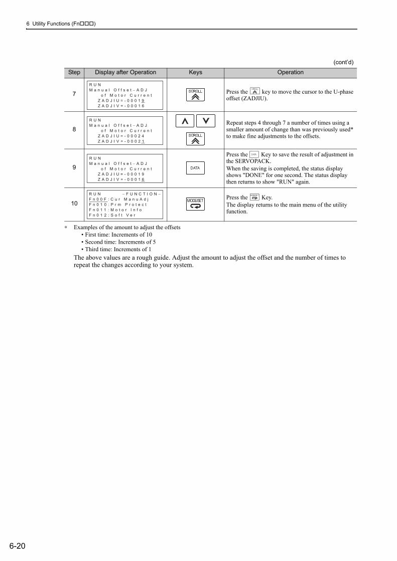
6 Utility Functions (Fn)
6-20
∗ Examples of the amount to adjust the offsets• First time: Increments of 10• Second time: Increments of 5• Third time: Increments of 1
The above values are a rough guide. Adjust the amount to adjust the offset and the number of times to repeat the changes according to your system.
7 Press the key to move the cursor to the U-phase offset (ZADJIU).
8Repeat steps 4 through 7 a number of times using a smaller amount of change than was previously used* to make fine adjustments to the offsets.
9
Press the Key to save the result of adjustment in the SERVOPACK.When the saving is completed, the status display shows "DONE" for one second. The status display then returns to show "RUN" again.
10Press the Key.The display returns to the main menu of the utility function.
(cont’d)
Step Display after Operation Keys Operation
R U NM a n u a l O f f s e t − A D J o f M o t o r C u r r e n t Z A D J I U = - 0 0 0 1 9 Z A D J I V = - 0 0 0 1 6
R U NM a n u a l O f f s e t − A D J o f M o t o r C u r r e n t Z A D J I U = - 0 0 0 2 4 Z A D J I V = - 0 0 0 2 1
R U NM a n u a l O f f s e t − A D J o f M o t o r C u r r e n t Z A D J I U = - 0 0 0 1 9 Z A D J I V = - 0 0 0 1 6
R U N − F U N C T I O N −F n 0 0 F : C u r M a n u A d jF n 0 1 0 : P r m P r o t e c tF n 0 1 1 : M o t o r I n f oF n 0 1 2 : S o f t V e r

6.12 Write Prohibited Setting (Fn010)
6-21
6
Util
ity F
unct
ions
(F
n
)
6.12 Write Prohibited Setting (Fn010)This function prevents changing parameters by mistake and sets restrictions on the execution of the utility function.
Parameter changes and execution of the utility function become restricted in the following manner when Write prohibited (P.0001) is assigned to the write prohibited setting (Fn010).• Parameters: Cannot be changed. If you attempt to change it, "NO-OP" will flash on the display and the
screen will return to the main menu. • Utility Function: Some functions cannot be executed. (Refer to the following table.) If you attempt to exe-
cute these utility functions, "NO-OP" will flash on the display and the screen will return to the main menu.
Parameter No. Function
Write Prohibited Setting
Reference Section
Fn000 Alarm history display Executable 6.2
Fn002 JOG operation Cannot be executed 6.3
Fn003 Origin search Cannot be executed 6.4
Fn004 Program JOG operation Cannot be executed 6.5
Fn005 Initializing parameter settings Cannot be executed 6.6
Fn006 Clearing alarm history Cannot be executed 6.7
Fn008 Absolute encoder multiturn reset and encoder alarm reset Cannot be executed 4.7.4
Fn00C Offset adjustment of analog monitor output Cannot be executed 6.8
Fn00D Gain adjustment of analog monitor output Cannot be executed 6.9
Fn00E Automatic offset-signal adjustment of the motor current detection signal
Cannot be executed 6.10
Fn00F Manual offset-signal adjustment of the motor current detection signal Cannot be executed 6.11
Fn010 Write prohibited setting – 6.12
Fn011 Servomotor model display Executable 6.13
Fn012 Software version display Executable 6.14
Fn013Multiturn limit value setting change when a multiturn limit dis-agreement alarm occurs Cannot be executed 4.7.7
Fn014 Resetting configuration error in option modules Cannot be executed 6.15
Fn01B Vibration detection level initialization Cannot be executed 6.16
Fn01E Display of SERVOPACK and servomotor ID Executable 6.17
Fn01F Display of servomotor ID in feedback option module Executable 6.18
Fn020 Origin setting Cannot be executed 6.19
Fn030 Software reset Executable 6.20
Fn200 Tuning-less levels setting Cannot be executed 5.2.2
Fn201 Advanced autotuning Cannot be executed 5.3.2
Fn202 Advanced autotuning by reference Cannot be executed 5.4.2
Fn203 One-parameter tuning Cannot be executed 5.5.2
Fn204 Anti-resonance control adjustment function Cannot be executed 5.6.2
Fn205 Vibration suppression function Cannot be executed 5.7.2
Fn206 EasyFFT Cannot be executed 6.21
Fn207 Online vibration monitor Cannot be executed 6.22

6 Utility Functions (Fn)
6-22
(1) Preparation
There are no tasks that must be performed before the execution.
(2) Operating Procedure
Follow the steps to set enable or disable writing. Setting values are as follows:• "P.0000": Write permitted (Releases write prohibited mode.) [Factory setting]• "P.0001": Write prohibited (Parameters become write prohibited from the next power ON.)
Note: To make the setting available, change the setting to P.0000 as shown in step 3.
Step Display after Operation Keys Operation
1
Press the Key to view the main menu for the utility function.
Use the or Key to move through the list and select Fn010.
2 Press the Key. The display changes to the Fn010 execution display.
3
Press the or Key to select one of the follow-ing settings.P.0000: Write permitted [Factory setting]P.0001: Write prohibited
4Press the Key. The setting value is written into the SERVOPACK, and the status display changes as follows: "BB" to "DONE" to "BB."
5 To enable the setting, turn the power supply to the SERVOPACK OFF and ON again.
B B − F U N C T I O N −F n 0 0 F : C u r M a n u A d jF n 0 1 0 : P r m P r o t e c tF n 0 1 1 : M o t o r I n f oF n 0 1 2 : S o f t V e r
B B P a r a m e t e r W r i t e P r o t e c t
P . 0 0 0 0
B B P a r a m e t e r W r i t e P r o t e c t
P . 0 0 0 1
B B P a r a m e t e r W r i t e P r o t e c t
P . 0 0 0 1

6.13 Servomotor Model Display (Fn011)
6-23
6
Util
ity F
unct
ions
(F
n
)
6.13 Servomotor Model Display (Fn011)This function is used to check the servomotor model, voltage, capacity, encoder type, and encoder resolution. If the SERVOPACK has been custom-made, you can also check the specification codes of SERVOPACKs.
(1) Preparation
There are no tasks that must be performed before the execution.
(2) Operating Procedure
Use the following procedure.
Step Display after Operation Keys Operation
1
Press the Key to view the main menu for the utility function.
Use the or Key to move through the list and select Fn011.
2
∗A single-turn absolute encoder can be used only with a direct drive motor.
Press the Key. The display changes to the Fn011 execution display and shows the information about the servomotor and encoder being used.
3 Press the Key. The display returns to the main menu of the utility function.
Servomotorcapacity
Servomotorinput voltage
6062636D213233343536373839
SGMAV
SGMSV
SGMGV
SGMJV
SGMPS
SGMCS-C
SGMCS-D
SGMCS-B
SGMCS-E
SGMCS-L
SGMCS-M
SGMCS-N
SGMCS-R
00 01
E N C O D E R 0 1 2 0 b i t
B B − M o t o r l n f o −T Y P E 6 0 A C 2 0 0 V
4 0 0 W
Servomotor Model
Encoder Type
Incremental
Multiturn absolute value
Absolute value per rotation*
Code Type
02
Encoder Resolution
13 bit
17 bit
20 bit
131720
ResolutionCode

6 Utility Functions (Fn)
6-24
6.14 Software Version Display (Fn012)Select Fn012 to check the SERVOPACK and encoder software version numbers.
(1) Preparation
There are no tasks that must be performed before the execution.
(2) Operating Procedure
Use the following procedure.
Step Display after Operation Keys Operation
1
Press the Key to view the main menu for the utility function.
Use the or Key to move through the list and select Fn012.
2
Press the Key. The display changes to the Fn012 execution display.The software versions of the SERVOPACK and the connected encoder will appear.Note: If the servomotor is not connected, "Not connect" is displayed.
3 Press the Key. The display returns to the main menu of the utility function.
B B − F U N C T I O N −F n 0 1 1 : M o t o r I n f oF n 0 1 2 : S o f t V e rF n 0 1 3 : M t u r n L m S e tF n 0 1 4 : O p t I n i t
B B − S o f t V e r −D R I V E R V e r . = 0 0 0 1E N C O D E R V e r . = 0 0 0 3
B B − F U N C T I O N −F n 0 1 1 : M o t o r I n f oF n 0 1 2 : S o f t V e rF n 0 1 3 : M t u r n L m S e tF n 0 1 4 : O p t I n i t

6.15 Resetting Configuration Errors in Option Modules (Fn014)
6-25
6
Util
ity F
unct
ions
(F
n
)
6.15 Resetting Configuration Errors in Option Modules (Fn014)The SERVOPACK with option module recognizes installation status and types of option modules that are con-nected to SERVOPACK. If an error is detected, the SERVOPACK issues an alarm. This function clears these alarms.
Note 1. Alarms related to option module can be cleared only by this function. These alarms cannot be cleared by alarm reset or turning OFF the main circuit power supply.
2. Before clearing the alarm, perform corrective action for the alarm.
(1) Preparation
The following condition must be met to clear detection alarms of the option module.• The write prohibited setting (Fn010) must be set to Write permitted (P.0000).
(2) Operating Procedure
Use the following procedure.
Step Display after Operation Keys Operation
1
Press the Key to view the main menu for the utility function.
Use the or Key to move through the list and select Fn014.
2 Press the Key. The display changes to the Fn014 execution display.
3 Press the or Key to select an option module to be cleared.
4 Press the Key. The display shown on the left appears.
5
Press the Key to clear the configuration error of the option module.The error is cleared and the status display shows "DONE" for one second. The status display then returns to step 3.
6 Press the Key. The display returns to the main menu of the utility function.
7 To enable the setting, turn the power supply to the SERVOPACK OFF and ON again.
B B − F U N C T I O N −F n 0 1 3 : M t u r n L m S e tF n 0 1 4 : O p t I n i tF n 0 1 B : V i b l v l I n i tF n 0 1 E : S v M o t O p I D
B B − O p t I n i t −
0 2 : S a f e t y O p t 0 3 : F e e d b a c k O p t
B B − O p t I n i t −
0 2 : S a f e t y O p t 0 3 : F e e d b a c k O p t
B B − O p t I n i t − F e e d b a c k O p t I n i t i a l i z e S t a r t : [ D A T A ] R e t u r n : [ S E T ]
B B − O p t I n i t −
0 2 : S a f e t y O p t 0 3 : F e e d b a c k O p t
B B − F U N C T I O N −F n 0 1 3 : M t u r n L m S e tF n 0 1 4 : O p t I n i tF n 0 1 B : V i b l L v l I n i tF n 0 1 E : S v M o t O p I D

6 Utility Functions (Fn)
6-26
6.16 Vibration Detection Level Initialization (Fn01B)This function detects vibration when servomotor is connected to a machine in operation and automatically adjusts the vibration detection level (Pn312) to output more exactly the vibration alarm (A.520) and the vibra-tion warning (A.911).
The vibration detection function detects vibration elements according to the motor speed.
If the vibration exceeds the detection level calculated by the following formula, the alarm or warning will be output according to the setting of vibration detection switch (Pn310).
• Use this function if the vibration alarm (A.520) or the vibration warning (A.911) is not output correctly when a vibration at the factory setting of the vibration detection level (Pn312) is detected. In other cases, it is not necessary to use this function.
• The vibration alarm or warning detection sensibility differs depending on the machine conditions. In this case, fine-tune the setting of the vibration detection sensitivity (Pn311) using the above detection level for-mula as a guide.
(1) Preparation
The following conditions must be met to initialize the vibration detection level.• The write prohibited setting (Fn010) must be set to Write permitted (P.0000).• The test without a motor function must be disabled (Pn00C.0 = 0).
Parameter Meaning When Enabled Classification
Pn310
n.0[Factory setting]
Does not detect vibration.
Immediately Setupn.1 Outputs the warning (A.911) when vibration is
detected.
n.2 Outputs the alarm (A.520) when vibration is detected.
Pn311Vibration Detection Sensitivity
ClassificationSetting Range Setting Unit Factory Setting When Enabled
50 to 500 1% 100 Immediately Tuning
• The vibration may not be detected because of improper servo gains. Also, not all kinds of vibrations can be detected. Use the detection result as a guideline.
• Set a proper moment of inertia ratio (Pn103). Improper setting may result in the vibra-tion alarm, warning misdetection, or non-detection.
• The references that are used to operate your system must be input to execute this function.
• Execute this function under the operating condition for which the vibration detection level should be set.
• Execute this function while the motor speed reaches at least 10% of its maximum.
Detection level = Vibration detection level (Pn312 [min-1]) × Vibration detection sensitivity (Pn311 [%])100
Speed Position Torque

6.16 Vibration Detection Level Initialization (Fn01B)
6-27
6
Util
ity F
unct
ions
(F
n
)
(2) Operating Procedure
Use the following procedure.
(3) Related Parameters
The following table lists parameters related to this function and their possibility of being changed while exe-cuting this function or of being changed automatically after executing this function.
• Parameters related to this functionThese are parameters that are used or referenced when executing this function.
• Allowed changes during execution of this functionYes: Parameters can be changed using SigmaWin+ while this function is being executed.No: Parameters cannot be changed using SigmaWin+ while this function is being executed.
• Automatic changes after execution of this functionYes: Parameter set values are automatically set or adjusted after execution of this function.No: Parameter set values are not automatically set or adjusted after execution of this function.
Step Display after Operation Keys Operation
1
Press the Key to view the main menu for the utility function.
Use the or Key to move through the list and select Fn01B.
2 Press the Key. The display changes to the Fn01B execution display.
3
Press the Key."Init" is displayed flashing, and the vibration level is detected and initialized. Note:Continues initialization until the Key is pressed again.
4Press the Key. The display changes from "Init" to "DONE," for one second and the new setting of Pn312 becomes enabled.
5 Press the Key. The display returns to the main menu of the utility function.
R U N − F U N C T I O N −F n 0 1 4 : O p t I n i tF n 0 1 B : V i b l v l I n i tF n 0 1 E : S v M o t O p I DF n 0 1 F : F B O p M o t I D
R U N V i b r a t i o n D e t e c t L e v e l I n i t S t a r t : [ D A T A ] R e t u r n : [ S E T ]
R U N V i b r a t i o n D e t e c t L e v e l I n i t
I n i t
R U N V i b r a t i o n D e t e c t L e v e l I n i t
D
R U N − F U N C T I O N −F n 0 1 4 : O p t I n i tF n 0 1 B : V i b l v l I n i tF n 0 1 E : S v M o t O p I DF n 0 1 F : F B O p M o t I D
Parameter Name Mid-execution changes
Automatic changes
Pn311 Vibration Detection Sensitivity Yes No
Pn312 Vibration Detection Level No Yes

6 Utility Functions (Fn)
6-28
6.17 Display of SERVOPACK and Servomotor ID (Fn01E)This function displays ID information for SERVOPACK, servomotor, encoder, and option module connected to the SERVOPACK. The ID information of some option modules (SGDV-OFA01A) is not stored in the SER-VOPACK. "Not available" will be displayed for these option modules.
The digital operator (model: JUSP-OP05A-1-E) or SigmaWin+ engineering tool is required to execute this function.
Refer to Σ-V Series User's Manual, Operation of Digital Operator (No.: SIEP S800000 55) for the operating procedure of the digital operator.
The following items can be displayed.
∗ If the option module is not connected, "Not connect" will be displayed after the module name.
(1) Preparation
There are no tasks that must be performed before the execution.
ID Items to be Displayed
SERVOPACK ID
• SERVOPACK model• SERVOPACK serial number• SERVOPACK manufacturing date• SERVOPACK input voltage (V)• Maximum applicable motor capacity (W)• Maximum applicable motor rated current (Arms)
Servomotor ID
• Servomotor model• Servomotor order number• Servomotor manufacturing date• Servomotor input voltage (V)• Servomotor capacity (W)• Servomotor rated current (Arms)
Encoder ID
• Encoder model• Encoder serial number• Encodermanufacturing date• Encoder type/resolution
Safety Option Module ID*
• Safety Option Module model• Safety Option Module serial number• Safety Option Module manufacturing date• Safety Option Module ID number
Feedback Option Mod-ule ID*
• Feedback Option Module model• Feedback Option Module serial number (Reserved area)• Feedback Option Module manufacturing date• Feedback Option Module ID

6.17 Display of SERVOPACK and Servomotor ID (Fn01E)
6-29
6
Util
ity F
unct
ions
(F
n
)
(2) Operating Procedure
Use the following procedure.
Step Display after Operation Keys Operation
1
Press the Key to view the main menu for the utility function.
Use the or Key to move through the list and select Fn01E.
2
Press the Key.The display changes to the Fn01E execution display.The SERVOPACK ID information is displayed. Use the or Key to scroll left and right and to view other information.
3
Press the Key.The servomotor ID information is displayed. Use the
or Key to scroll left and right and to view other information.
4
Press the Key.The encoder ID information is displayed.
Use the or Key to scroll left and right and to view other information.
5Press the Key.The display returns to the main menu of the utility function.
R U N − F U N C T I O N −F n 0 1 B : V i b l v l I n i tF n 0 1 E : S v M o t O p I DF n 0 1 F : F B O p M o t I DF n 0 2 0 : S − O r i g S e t
B B − S v M o t O p I D −D r i v e r S G D V − R 7 0 A 1 1 A D 0 0 2 4 1 2 3 4 5 9 0 0 0 1 0 7 . 0 4 2 0 0 V , 5 0 W
Serial number
Manufacturing date
SERVOPACK model
SERVOPACK input voltage
Motor capacity
B B − S v M o t O p I D −M o t o r S G M A V − A 5 A 3 A 2 1 1 2 3 4 5 6 7 8 9 0 0 0 0 0 0 0 7 . 0 4 2 0 0 V , 5 0 W
Motor order number
Motor manufacturing date
Servomotor model
Motor input voltage
Motor capacity
B B − S v M o t O p I D −E n c o d e r U T V I H − B 2 0 E A K 2 4 7 − 0 2 2 5 E 0 0 2 0 0 0 7 . 0 4 2 0 b i t − A B S
Encoder serial number
Encoder manufacturing date
Encoder model
Encoderresolution
Encoder type
R U N − F U N C T I O N −F n 0 1 B : V i b l v l I n i tF n 0 1 E : S v M o t O p I DF n 0 1 F : F B O p M o t I DF n 0 2 0 : S − O r i g S e t

6 Utility Functions (Fn)
6-30
6.18 Display of Servomotor ID in Feedback Option Module (Fn01F)This function displays ID information for servomotor and encoder in Feedback Option Module connected to the SERVOPACK. If the option module is not connected, "Not connect" will be displayed after the module name.
The digital operator (model: JUSP-OP05A-1-E) or SigmaWin+ engineering tool is required to execute this function.
Refer to Σ-V Series User's Manual, Operation of Digital Operator (No.: SIEP S800000 55) for the operating procedure of the digital operator.
The following items can be displayed.
(1) Preparation
There are no tasks that must be performed before the execution.
(2) Operating Procedure
Use the following procedure.
∗ When fully-closed loop control is being used, step 2 is not included.
ID Items to be Displayed
Servomotor ID
• Servomotor model• Servomotor order number• Servomotor input voltage (V)• Servomotor capacity (W)• Servomotor rated current (Arms)
Encoder ID
• Encoder model• Encoder serial number• Encoder type/resolution
(Two types of resolution display available: Number of bits and number of pulses/rev.)
Step Display after Operation Keys Operation
1
Press the Key to view the main menu for the utility function.
Use the or Key to move through the list and select Fn01F.
2*
Press the Key.The display changes to the Fn01F execution display.The servomotor ID information is displayed. Use the
or Key to scroll left and right and to view other information.
3
Press the Key.The encoder ID information is displayed.
Use the or Key to scroll left and right and to view other information.
4Press the Key.The display returns to the main menu of the utility function.
B B − F U N C T I O N −F n 0 1 E : S v M o t O p I DF n 0 1 F : F B O p M o t I DF n 0 2 0 : S − O r i g S e tF n 0 3 0 : S o f t R e s e t
B B − F B O p M o t I D −M o t o rS G M − 0 4 A 3 1 2R 1 0 4 1 9 − 5 1 1 − D K 5 0 0 02 0 0 V , 4 0 0 W
Serial numberServomotor model
Input voltage Capacity
B B − F B O p M o t I D −E n c o d e rU T S T H − U 1 3 D BS e r i a l N o .1 3 b i t − I N C
Encoder type/resolutionEncoder model
B B − F U N C T I O N −F n 0 1 E : S v M o t O p I DF n 0 1 F : F B O p M o t I DF n 0 2 0 : S − O r i g S e tF n 0 3 0 : S o f t R e s e t

6.19 Origin Setting (Fn020)
6-31
6
Util
ity F
unct
ions
(F
n
)
6.19 Origin Setting (Fn020)When using an external absolute encoder for fully-closed loop control, this function is used to set the current position of the external absolute encoder as the origin (zero point position).
This function can be used with the following products.Mitutoyo CorporationABS ST780A seriesModel: ABS ST78A/ST78AL
(1) Preparation
The following conditions must be met to set the origin.
• The write prohibited setting (Fn010) must be set to Write permitted (P.0000).• The servomotor power must be OFF.
(2) Operating Procedure
Use the following procedure.
• After execution of origin setting, the servo ready (/S-RDY) signal will turn OFF (open) because the system position data will have been changed. Always turn the power supply to the SERVOPACK OFF and ON again.
Step Display after Operation Keys Operation
1
Press the Key to view the main menu for the utility function.
Use the or Key to move through the list and select Fn020.
2 Press the Key. The display changes to the Fn020 execution display.
3 Press the or Key to "ORGSET5".
4
Press the key to start setting the origin. The mes-sage, "Scale Origin Set," flashes while the origin is being set. After the origin has been successfully set, the displayed status changes as follows: "BB" to "DONE" to "BB".
5 To enable the setting, turn the power supply to the SERVOPACK OFF and ON again.
B B − F U N C T I O N −F n 0 1 F : F B O p M o t I DF n 0 2 0 : S − O r i g S e tF n 0 3 0 : S o f t R e s e tF n 0 8 0 : P o l e D e t e c t
B B
S c a l e O r i g i n S e t
O R G S E T 1
B B
S c a l e O r i g i n S e t
O R G S E T 5
B B
S c a l e O r i g i n S e t

6 Utility Functions (Fn)
6-32
6.20 Software Reset (Fn030)This function enables resetting the SERVOPACK internally from software. This function is used when reset-ting alarms and changing the settings of parameters that normally require restarting the SERVOPACK. Parameters settings can also be enabled without turning the SERVOPACK OFF and ON again.
(1) Preparation
The following condition must be met to perform a software reset.
• The servomotor power must be OFF.
(2) Operating Procedure
Use the following procedure.
• Start software reset operation after the servomotor power is OFF.
• This function resets the SERVOPACK independently of host controller. The SERVO-PACK carries out the same processing as when the power supply is turned ON and outputs the ALM signal. The status of other output signals may be forcibly changed.
Step Display after Operation Keys Operation
1
Press the Key to view the main menu for the utility function.
Use the or Key to move through the list and select Fn030.
2 Press the Key. The display changes to the Fn030 execution display.
3 Press the or Key to select "RESET5".
4Press the Key to execute the software reset. After the software reset starts, "RESET5" will no lon-ger be displayed.
5 −
After the reset has been successfully completed, the screen which appears when the power is turned ON will be displayed. The screen will then show parame-ters or monitor displays.
6Press the Key.The display returns to the main menu of the utility function.
B B − F U N C T I O N −F n 0 2 0 : S − O r i g S e tF n 0 3 0 : S o f t R e s e tF n 0 8 0 : P o l e D e t e c t F n 2 0 0 : T u n e L v l S e t
B B
S o f t w a r e R e s e t
R E S E T 1
B B
S o f t w a r e R e s e t
R E S E T 5
B B
S o f t w a r e R e s e t
F i l e F i r s t L o a d i n g P l e a s e W a i t . . .
B B − F U N C T I O N −F n 0 2 0 : S − O r i g S e tF n 0 3 0 : S o f t R e s e tF n 0 8 0 : P o l e D e t e c t F n 2 0 0 : T u n e L v l S e t

6.21 EasyFFT (Fn206)
6-33
6
Util
ity F
unct
ions
(F
n
)
6.21 EasyFFT (Fn206)EasyFFT sends a frequency waveform reference from the SERVOPACK to the servomotor and slightly rotates the servomotor several times over a certain period, thus causing machine vibration. The SERVOPACK detects the resonance frequency from the generated vibration and makes notch filter settings according to the reso-nance frequency detection. The notch filter is effective for the elimination of high-frequency vibration and noise.
Execute this function after the servomotor power is turned OFF if there is high-frequency vibration or noise during operation.
In addition to this function, online vibration monitor (Fn207) can be used to detect machine vibration and automatically make notch filter settings.
If a Σ-V Series SERVOPACK is used to make adjustments, it is recommended to use advanced autotuning. This built-in EasyFFT function is used to maintain interchangeability with previous models. There is normally no need to use it.
(1) Preparation
The following conditions must be met to perform EasyFFT.
• The write prohibited setting (Fn010) must be set to Write permitted (P.0000).• The main circuit power supply must be ON.• All alarms must be cleared.• The hardwire baseblock (HWBB) must be disabled.• The servomotor power must be OFF.• There must be no overtravel.• The test without a motor function must be disabled (Pn00C.0 = 0).• An external reference must not be input.
WARNING• The servomotor rotates slightly when EasyFFT is executed. Do not touch the servomotor or machine
during execution of EasyFFT, otherwise injury may result.
CAUTION• Use the EasyFFT when the servo gain is low, such as in the initial stage of servo adjustment. If EasyFFT
is executed after increasing the gain, the servo system may vibrate depending on the machine character-istics or gain balance.
Rotates the shaft slightly
Slightmovement
SERVOPACK
Periodicwaveform reference
Response
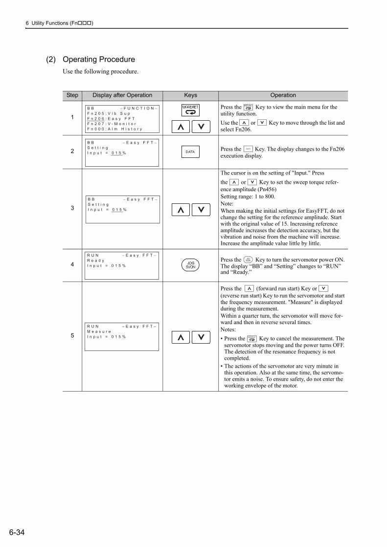
6 Utility Functions (Fn)
6-34
(2) Operating Procedure
Use the following procedure.
Step Display after Operation Keys Operation
1
Press the Key to view the main menu for the utility function.
Use the or Key to move through the list and select Fn206.
2 Press the Key. The display changes to the Fn206 execution display.
3
The cursor is on the setting of "Input." Press
the or Key to set the sweep torque refer-ence amplitude (Pn456)Setting range: 1 to 800.Note:When making the initial settings for EasyFFT, do not change the setting for the reference amplitude. Start with the original value of 15. Increasing reference amplitude increases the detection accuracy, but the vibration and noise from the machine will increase. Increase the amplitude value little by little.
4Press the Key to turn the servomotor power ON. The display “BB” and “Setting” changes to “RUN” and “Ready.”
5
Press the (forward run start) Key or (reverse run start) Key to run the servomotor and start the frequency measurement. "Measure" is displayed during the measurement.Within a quarter turn, the servomotor will move for-ward and then in reverse several times.Notes:
• Press the Key to cancel the measurement. The servomotor stops moving and the power turns OFF. The detection of the resonance frequency is not completed.
• The actions of the servomotor are very minute in this operation. Also at the same time, the servomo-tor emits a noise. To ensure safety, do not enter the working envelope of the motor.
B B − F U N C T I O N −F n 2 0 5 : V i b S u pF n 2 0 6 : E a s y F F TF n 2 0 7 : V - M o n i t o rF n 0 0 0 : A l m H i s t o r y
B B − E a s y F F T −S e t t i n gI n p u t = 0 1 5 %
B B − E a s y F F T −S e t t i n gI n p u t = 0 1 5 %
R U N − E a s y F F T −R e a d yI n p u t = 0 1 5 %
R U N − E a s y F F T −M e a s u r eI n p u t = 0 1 5 %

6.21 EasyFFT (Fn206)
6-35
6
Util
ity F
unct
ions
(F
n
)
6
When the detection processing is successfully com-pleted, "Measure" stops flashing and the results and the notch filter value to be set are displayed. If the processing was not completed, "No Measure" is dis-played. To check the results, go to step 8.< Important >If two seconds or more are required for the operation although detection was successfully completed, the detection accuracy might be insufficient. Increasing reference amplitude more than 15 increases the detec-tion accuracy, but the vibration and noise from the machine will increase. Increase the amplitude value little by little.Notes: • If a notch filter has been set and is being used, "*"
is displayed on the second line.• If the first stage notch filter has been set, the sec-
ond stage notch filter value is displayed. If the first and second stage notch filters have been set, only the result of frequency detection is displayed.
7
To exit the EasyFFT function at this stage, press
the Key. The power to the servomotor is turned OFF and the display returns to the main menu of the utility function.To remeasure the resonance frequency, press the
Key to return to step 4 and then execute steps 5 to 7.
8
Press the Key after the normal completion of frequency detection. The notch filter frequencies are automatically updated to the optimum values.The status display shows "DONE" and the display shown on the left appears.If the first stage notch filter frequency has been set (Pn408.0 = 1), the second stage notch filter frequency (Pn 40C) will automatically be updated. Notes:• If the first stage or the second stage notch filter fre-
quency has already been set (Pn408 = n.11), the notch filter frequency cannot be set.
• If the frequency detected by this function is not used, set the notch filter to be invalid (Pn408.0 = 0).
9Press the Key.The servomotor enters a baseblocked status. The dis-play returns to the main menu of the utility function.
10 To enable the setting, turn the power supply to the SERVOPACK OFF and ON again.
(cont’d)
Step Display after Operation Keys Operation
B B − E a s y F F T −R e s u l tI n p u t = 0 1 5 %R e s = 1 2 5 0 H zF i l t e r 1 1 2 5 0 H z
B B − E a s y F F T −R e a d yI n p u t = 0 1 5 %
D − E a s y F F T −R e s u l tI n p u t = 0 1 5 %R e s = 1 2 5 0 H zF i l t e r 1 1 2 5 0 H z
B B − F U N C T I O N −F n 2 0 5 : V i b S u pF n 2 0 6 : E a s y F F TF n 2 0 7 : V - M o n i t o rF n 0 0 0 : A l m H i s t o r y

6 Utility Functions (Fn)
6-36
(3) Related Parameters
The following table lists parameters related to this function and their possibility of being changed while exe-cuting this function or of being changed automatically after executing this function.
• Parameters related to this functionThese are parameters that are used or referenced when executing this function.
• Allowed changes during execution of this functionYes : Parameters can be changed using SigmaWin+ while this function is being executed.No : Parameters cannot be changed using SigmaWin+ while this function is being executed.
• Automatic changes after execution of this functionYes : Parameter set values are automatically set or adjusted after execution of this function.No : Parameter set values are not automatically set or adjusted after execution of this function.
Parameter Name Mid-execution changes
Automatic changes
Pn408 Torque Related Function Switch Yes Yes
Pn409 1st Notch Filter Frequency No Yes
Pn40A 1st Notch Filter Q Value No No
Pn40C 2nd Notch Filter Frequency No Yes
Pn40D 2nd Notch Filter Q Value No No
Pn456 Sweep Torque Reference Amplitude No No
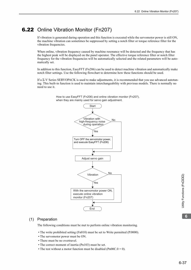
6.22 Online Vibration Monitor (Fn207)
6-37
6
Util
ity F
unct
ions
(F
n
)
6.22 Online Vibration Monitor (Fn207)If vibration is generated during operation and this function is executed while the servomotor power is still ON, the machine vibration can sometimes be suppressed by setting a notch filter or torque reference filter for the vibration frequencies.
When online, vibration frequency caused by machine resonance will be detected and the frequency that has the highest peak will be displayed on the panel operator. The effective torque reference filter or notch filter frequency for the vibration frequencies will be automatically selected and the related parameters will be auto-matically set.
In addition to this function, EasyFFT (Fn206) can be used to detect machine vibration and automatically make notch filter settings. Use the following flowchart to determine how these functions should be used.
If a Σ-V Series SERVOPACK is used to make adjustments, it is recommended that you use advanced autotun-ing. This built-in function is used to maintain interchangeability with previous models. There is normally no need to use it.
(1) Preparation
The following conditions must be met to perform online vibration monitoring.
• The write prohibited setting (Fn010) must be set to Write permitted (P.0000).• The servomotor power must be ON.• There must be no overtravel.• The correct moment of inertia (Pn103) must be set.• The test without a motor function must be disabled (Pn00C.0 = 0).
Start
How to use EasyFFT (Fn206) and online vibration monitor (Fn207),when they are mainly used for servo gain adjustment.
End
Vibration with high-frequency noise
during operationNo
No
Yes
Yes
Adjust servo gain
Vibration
With the servomotor power ON, execute online vibration monitor (Fn207)
Turn OFF the servomotor power, and execute EasyFFT (Fn206)

6 Utility Functions (Fn)
6-38
(2) Operating Procedure
Use the following procedure.
Step Display after Operation Keys Operation
1
Press the Key to view the main menu for the utility function.
Use the or Key to move through the list and select Fn207.
2 Press the Key.The display changes to the Fn207 execution display.
3
Press the Key for at least one second to start
vibration detection. The Key must be pressed until "Measure" flashes on the display. Note:After this message appears, the Key does not have to be pressed and the detection continues auto-matically.
4
When the vibration detection has completed, "Mea-sure" stops flashing and the detection processing ends automatically. When the detection processing has completed normally, the vibrations with three largest peak values in vibration frequency are displayed for F1, F2, and F3.Notes:
• Press the Key to quit the online vibration monitor function. The display returns to the main menu of the utility function.
• A detected frequency can be displayed. For a vibra-tion with undetectable peak frequency, "----" is dis-played. If no frequency was detected, "----" is displayed for F1, F2, and F3.
• If the frequency could not be successfully detected, "NO MONITOR" is displayed.
5
After the detection has normally completed, press the
Key. The optimum frequency (time constant) of notch filter or torque reference filter for F1 is set automatically. At the same time, the parameter Pn409 is updated for a notch filter, or the parameter Pn401 is updated for a torque reference filter.After the setting is successfully completed, "DONE" flashes.
6Press the Key.The display returns to the main menu of the utility function.
R U N − F U N C T I O N −F n 2 0 6 : E a s y F F TF n 2 0 7 : V − M o n i t o rF n 0 0 0 : A l m H i s t o r yF n 0 0 1 : J O G
R U N − V − M O N I T O R −M e a s u r eF 1 = − − − −F 2 = − − − −F 3 = − − − −
R U N − V − M O N I T O R −M e a s u r eF 1 = − − − −F 2 = − − − −F 3 = − − − −
R U N − V − M O N I T O R −M e a s u r eF 1 = 0 8 5 0 [ H z ]F 2 = 1 6 0 0 [ H z ]F 3 = 0 2 2 5 [ H z ]
D O N E − V − M O N I T O R −S E T T I N G D O N EF 1 = 0 8 5 0 [ H z ]F 2 = 1 6 0 0 [ H z ]F 3 = 0 2 2 5 [ H z ]
R U N − F U N C T I O N −F n 2 0 6 : E a s y F F TF n 2 0 7 : V − M o n i t o rF n 0 0 0 : A l m H i s t o r yF n 0 0 1 : J O G

6.22 Online Vibration Monitor (Fn207)
6-39
6
Util
ity F
unct
ions
(F
n
)
(3) Related Parameters
The following table lists parameters related to this function and their possibility of being changed while exe-cuting this function or of being changed automatically after executing this function.
• Parameters related to this functionThese are parameters that are used or referenced when executing this function.
• Allowed changes during execution of this functionYes : Parameters can be changed using SigmaWin+ while this function is being executed.No : Parameters cannot be changed using SigmaWin+ while this function is being executed.
• Automatic changes after execution of this functionYes : Parameter set values are automatically set or adjusted after execution of this function.No : Parameter set values are not automatically set or adjusted after execution of this function.
Parameter Name Mid-execution changes
Automatic changes
Pn401 Torque Reference Filter Time Constant No Yes
Pn408 Torque Related Function Switch Yes Yes
Pn409 1st Notch Filter Frequency No Yes
Pn40A 1st Notch Filter Q Value No No
Pn40C 2nd Notch Filter Frequency No No
Pn40D 2nd Notch Filter Q Value No No

7-1
7
Mo
nito
r D
ispl
ays
(Un
)
7Monitor Displays (Un)
7.1 List of Monitor Displays . . . . . . . . . . . . . . . . . . . . . . . . . . . . . . . . . . . . . . .7-2
7.2 Viewing Monitor Displays . . . . . . . . . . . . . . . . . . . . . . . . . . . . . . . . . . . . . .7-3
7.3 Monitoring Input Signals . . . . . . . . . . . . . . . . . . . . . . . . . . . . . . . . . . . . . .7-47.3.1 Interpreting Input Signal Display Status . . . . . . . . . . . . . . . . . . . . . . . . . . . . . . . . . . . . 7-47.3.2 Input Signal Display Example . . . . . . . . . . . . . . . . . . . . . . . . . . . . . . . . . . . . . . . . . . . 7-5
7.4 Monitoring Output Signals . . . . . . . . . . . . . . . . . . . . . . . . . . . . . . . . . . . . .7-67.4.1 Interpreting Output Signal Display Status . . . . . . . . . . . . . . . . . . . . . . . . . . . . . . . . . . 7-67.4.2 Output Signal Display Example . . . . . . . . . . . . . . . . . . . . . . . . . . . . . . . . . . . . . . . . . . 7-6
7.5 Monitoring Safety Input Signals . . . . . . . . . . . . . . . . . . . . . . . . . . . . . . . . .7-77.5.1 Interpreting Safety Input Signal Display Status . . . . . . . . . . . . . . . . . . . . . . . . . . . . . . 7-77.5.2 Safety Input Signal Display Example . . . . . . . . . . . . . . . . . . . . . . . . . . . . . . . . . . . . . . 7-7

7 Monitor Displays (Un)
7-2
7.1 List of Monitor DisplaysThe monitor displays can be used for monitoring the I/O signal status, and SERVOPACK internal status.
Refer to the following table.
∗1. For details, refer to 4.4.3 Electronic Gear.∗2. For details, refer to 7.3 Monitoring Input Signals.∗3. For details, refer to 7.4 Monitoring Output Signals.∗4. For details, refer to 8.3.3 Setting Encoder Output Pulses (PAO, PBO, and PCO).∗5. This monitor can be used only with SGDV-B SERVOPACKs. For details, refer to 2 Installation in the
Σ-V Series User’s Manual, Setup, Rotational Motor (No.: SIEP S800000 43).
Parameter No.
Description Unit
Un000 Motor rotating speed min-1
Un001 Speed reference min-1
Un002 Internal torque reference (percentage of the rated torque) %
Un003 Rotational angle 1 (encoder pulses from the phase-C origin: decimal display) encoder pulse*1
Un004 Rotational angle 2 (from polarity origin (electric angle)) deg
Un005*2 Input signal monitor −
Un006*3 Output signal monitor −
Un007 Input reference pulse speed (valid only in position control) min-1
Un008 Position error amount (valid only in position control) reference unit
Un009 Accumulated load ratio (in percentage to the rated torque: effective torque in cycle of 10 seconds) %
Un00ARegenerative load ratio (as a percentage of the processable regenerative power: regenerative power consumption in cycle of 10 seconds)
%
Un00BPower consumed by DB resistance(in percentage to the processable power at DB activation: dis-played in cycle of 10 seconds)
%
Un00C Input reference pulse counter reference unit
Un00D Feedback pulse counter encoder pulse*1
Un00E Fully-closed feedback pulse counter external encoder resolution*4
Un012 Total operation time 100 ms
Un013 Feedback pulse counter reference unit
Un014 Effective gain monitor (gain settings 1 = 1, gain settings 2 = 2) −
Un015 Safety I/O signal monitor −
Un020 Motor rated speed min-1
Un021 Motor maximum speed min-1
Un022*5Installation environment monitor(Operation conditions in various environments can be moni-tored.)
%
Un030 The current backlash compensation value 0.1 reference unit
Un031 Backlash compensation setting limit value 0.1 reference unit

7.2 Viewing Monitor Displays
7-3
7
Mo
nito
r D
ispl
ays
(Un
)
7.2 Viewing Monitor DisplaysThe monitor display can be checked or viewed in the Parameter/Monitor (-PRM/MON-) window of the digital operator.
The following figure shows four factory settings that are first displayed if viewing monitor displays.
To view any items that are not shown, press the or Key to scroll through the list.
Indicates that the value of Un000(motor rotating speed) is 0 min-1.
U n 0 0 0 = 0 0 0 0 0
U n 0 0 1 = 0 0 0 0 0
U n 0 0 2 = 0 0 0 0 0
U n 0 0 3 = 0 0 0 0 0
U n 0 0 4 = 0 0 0 9 0
U n 0 0 D = 0 0 0 0 0 0 0 0
Motor rotating speed
Speed reference
Rotational angle 1 (encoder pulses from the phase-C origin)
Rotation angle 2 (from polarity origin (electric angle))
Feedback pulse counter
Internal torque reference

7 Monitor Displays (Un)
7.3.1 Interpreting Input Signal Display Status
7-4
7.3 Monitoring Input SignalsThe status of input signals can be checked with the input signal monitor (Un005). The procedure for the method of interpreting the display and a display example are shown below.
7.3.1 Interpreting Input Signal Display StatusThe input signal monitor (Un005) can be read in the following way. The upper level indicates OFF, and the lower level indicates ON. All undefined digits are shown in the lower level (ON).
<NOTE>Input signals use the following circuit configuration.OFF: OpenON: Short-circuitedExample
Display LEDNumber Input Terminal Name
Signal Name (Factory Setting)
1 CN1-13 /SI0
2 CN1-7 P-OT
3 CN1-8 N-OT
4 CN1-9 /DEC
5 CN1-10 /EXT1
6 CN1-11 /EXT2
7 CN1-12 /EXT3
8 – Reserved
U n 0 0 5 =
8 7 6 5 4 3 2 1 digit
OFF (open)

7.3 Monitoring Input Signals
7-5
7
Mo
nito
r D
ispl
ays
(Un
)
7.3.2 Input Signal Display ExampleInput signals are displayed as shown below.
• When the /DEC signal is ON
• When the /DEC signal is OFF
• When the P-OT signal is activated
U n 0 0 5 =
8 7 6 5 4 3 2 1 digit
The fourth digitis in the lower level.
U n 0 0 5 =
8 7 6 5 4 3 2 1 digit
The fourth digitis in the upper level.
U n 0 0 5 =
8 7 6 5 4 3 2 1 digit
The second digitis in the upper level.

7 Monitor Displays (Un)
7.4.1 Interpreting Output Signal Display Status
7-6
7.4 Monitoring Output SignalsThe status of output signals can be checked with the output signal monitor (Un006). The procedure for the method of interpreting the display and a display example are shown below.
7.4.1 Interpreting Output Signal Display StatusThe output signal monitor (Un006) can be read in the following way. The upper level indicates OFF, and the lower level indicates ON. All undefined digits are shown in the lower level (ON).
<NOTE>Output signals use the following circuit configuration.OFF: Transistor OFFON: Transistor ONExample
7.4.2 Output Signal Display ExampleOutput signals are displayed as shown below.
• When the ALM signal is OFF
Display LED Number
Output Terminal NameSignal Name
(Factory Setting)
1 CN1-3, -4 ALM
2 CN1-1, -2 /BK
3 CN1-23, -24 SO2
4 CN1-25, -26 SO3
5 − Reserved
6 − Reserved
7 − Reserved
8 − Reserved
U n 0 0 6 =
8 7 6 5 4 3 2 1 digit
ON: Transistor ON
U n 0 0 6 =
8 7 6 5 4 3 2 1 digit
The first digit isin the upper level.

7.5 Monitoring Safety Input Signals
7-7
7
Mo
nito
r D
ispl
ays
(Un
)
7.5 Monitoring Safety Input SignalsThe status of safety input signals can be checked with the safety I/O signal monitor (Un015). The procedure for the method of interpreting the display and a display example are shown below.
7.5.1 Interpreting Safety Input Signal Display StatusThe safety I/O signal monitor (Un015) can be read in the following way. The upper level indicates ON, and the lower level indicates OFF. All undefined digits are shown in the lower level (OFF).
Note: Input signals use the following circuit configuration.• OFF: Open• ON: Short-circuited
Example
7.5.2 Safety Input Signal Display ExampleSafety input signals are displayed as shown below.
• When the /HWBB1 signal turns OFF to activate the HWBB function
Display LED Number Input Terminal Name Signal Name
1 CN8-3, -4 /HWBB1
2 CN8-5, -6 /HWBB2
3 − Reserved
4 − Reserved
5 − Reserved
6 − Reserved
7 − Reserved
8 − Reserved
U n 0 1 5 =
8 7 6 5 4 3 2 1 digit
ON (short-circuited)
U n 0 1 5 =
8 7 6 5 4 3 2 1 digit
The first digit isin the lower level.

8-1
8
Ful
ly-c
lose
d Lo
op C
ontr
ol
8Fully-closed Loop Control
8.1 System Configuration and Connection Example for SERVOPACK with Fully-closed Loop Control . . . . . . . . . . . . . . . . . . .8-2
8.1.1 System Configuration . . . . . . . . . . . . . . . . . . . . . . . . . . . . . . . . . . . . . . . . . . . . . . . . . 8-28.1.2 Internal Block Diagram of Fully-closed Loop Control . . . . . . . . . . . . . . . . . . . . . . . . . 8-38.1.3 Serial Converter Unit . . . . . . . . . . . . . . . . . . . . . . . . . . . . . . . . . . . . . . . . . . . . . . . . . . 8-48.1.4 Example of Connections to External Encoders . . . . . . . . . . . . . . . . . . . . . . . . . . . . . . 8-68.1.5 Encoder Output Pulse Signals from SERVOPACK with an External Encoder
by Renishaw plc . . . . . . . . . . . . . . . . . . . . . . . . . . . . . . . . . . . . . . . . . . . . . . . . . . . . . 8-78.1.6 Precautions When Using an External Incremental Encoder by Magnescale . . . . . . . 8-8
8.2 SERVOPACK Startup Procedure . . . . . . . . . . . . . . . . . . . . . . . . . . . . . . 8-12
8.3 Parameter Settings for Fully-closed Loop Control . . . . . . . . . . . . . . . . .8-148.3.1 Motor Rotation Direction . . . . . . . . . . . . . . . . . . . . . . . . . . . . . . . . . . . . . . . . . . . . . . 8-158.3.2 Sine Wave Pitch (Frequency) for an External Encoder . . . . . . . . . . . . . . . . . . . . . . . 8-178.3.3 Setting Encoder Output Pulses (PAO, PBO, and PCO) . . . . . . . . . . . . . . . . . . . . . . 8-178.3.4 External Absolute Encoder Data Reception Sequence . . . . . . . . . . . . . . . . . . . . . . . 8-188.3.5 Electronic Gear . . . . . . . . . . . . . . . . . . . . . . . . . . . . . . . . . . . . . . . . . . . . . . . . . . . . . 8-218.3.6 Alarm Detection . . . . . . . . . . . . . . . . . . . . . . . . . . . . . . . . . . . . . . . . . . . . . . . . . . . . . 8-228.3.7 Analog Monitor Signal . . . . . . . . . . . . . . . . . . . . . . . . . . . . . . . . . . . . . . . . . . . . . . . . 8-238.3.8 Speed Feedback Method during Fully-closed Loop Control . . . . . . . . . . . . . . . . . . . 8-23

8 Fully-closed Loop Control
8.1.1 System Configuration
8-2
8.1 System Configuration and Connection Example for SERVOPACK with Fully-closed Loop ControlThis section describes the system configuration and connection example for the SERVOPACK with fully-closed loop control.
8.1.1 System ConfigurationThe following figure shows an example of the system configuration.
∗ The connected devices and cables depend on the type of external encoder (linear scale).Note 1. For details on the power supply and peripheral devices, refer to 1.5 Examples of Servo System Configurations.
2. In fully-closed loop control, rattling or twisting of mechanical parts may cause vibration, destabilizing the posi-tioning process.
Serial converter unit*
External encoder cable*
Connection cable forserial converter unit*
External encoder(Not included)
Servomotormain circuit cable
Model: JZDP-D00 -000-E
SERVOPACK with Fully-closed Module Model: SGDV001

8.1 System Configuration and Connection Example for SERVOPACK with Fully-closed Loop Control
8-3
8
Ful
ly-c
lose
d Lo
op C
ontr
ol
8.1.2 Internal Block Diagram of Fully-closed Loop ControlInternal block diagram of fully-closed loop control is shown below.
With Position Control
∗ The connected devices depend on the type of external encoder (linear scale).Note: Either an incremental or an absolute encoder can be used. When the absolute encoder is used, set 1 to Pn002.2 (use
the absolute encoder as an incremental encoder).
With Speed Control
∗ The connected devices depend on the type of external encoder (linear scale).
Elec-tronicgear
MECHATROLINKmove command
Encoderoutputpulse
Error counter
Speedloop
Alarmdetection
Divider
Machine
SERVOPACK
Positioncontrolloop
Serialconversion
Motor
A.d10
Encoder
External encoder
Speed conversion
Speed feedback
Electronic gear1
MECHATROLINK Monitor data
Pn22A
Speed conversion
Unit conversionPn20A
*
SERVOPACK
Encoderoutputpulse
Divider
Speedloop MachineMotor
Encoder
External encoder
Speed conversionSpeed feedback
Serialconversion
MECHATROLINKmove command
Electronic gear
1MECHATROLINK monitor data
Pn22A
Speed conversion
Unit conversionPn20A Alarm
detectionA.d10
*

8 Fully-closed Loop Control
8.1.3 Serial Converter Unit
8-4
8.1.3 Serial Converter UnitThis section provides the specification of the serial converter unit.
(1) Model: JZDP-D00-000-E
Characteristics and Specifications
∗ Input a value within the specified range. Otherwise, incorrect position information is output, and the device may be damaged.
Items Specifications
Electrical Characteristics
Power Supply Voltage +5.0 V±5%, ripple content 5% max.
Current Consumption 120 mA Typ. 350 mA max.
Signal Resolution 1/256 pitch (1 cycle) of input 2-phase sine wave pitch
Max. Response Frequency 250 kHz
Analog Input Signals ∗
(cos, sin, Ref)Differential input amplitude: 0.4 V to 1.2 VInput signal level: 1.5 V to 3.5 V
Output Signal Position data, alarms
Output Method Serial data communications
Output CircuitBalanced type transceiver (SN75LBC176 or the equivalent), internal terminating resistor: 120 Ω
Mechanical Characteristics
Approx. Mass 150 g
Vibration Resistance 98 m/s2 max. (10 to 2500 Hz) in three directions
Shock Resistance 980 m/s2, (11 ms) two times in three directions
Environmental Conditions
Surrounding air Temperature 0 °C to 55 °C
Storage Temperature -20°C to +80 °C
Humidity 20% to 90%RH (without condensation)
Altitude 1000 m max.

8.1 System Configuration and Connection Example for SERVOPACK with Fully-closed Loop Control
8-5
8
Ful
ly-c
lose
d Lo
op C
ontr
ol
(2) Analog Signal Input Timing
Input the analog signals with the timing shown in the following figure.
The /cos and /sin signals are the differential signals when the cos and sin signals are shifted 180°. The specifi-cations of the cos, /cos, sin, and /sin signals are identical except for the phases.
The Ref and /Ref signals are input to the comparator. Input a signal that will exceed the hysteresis of the com-parator (i.e., the broken lines in the following figure).
When they are crossed, the output data will be counted up.
∗1. If the analog signal amplitude declines to approximately 0.35 V because of the differential amplitude, the serial con-verter unit will output an alarm.
∗2. This is the hysteresis width.
• Never perform insulation resistance and withstand voltage tests.
• When low-voltage analog signals are input to the serial converter unit, noise influence on the analog signals affects the unit’s ability to output correct position information. The analog cable must be as short as possible and shielded.
• Use the serial converter unit in a location without gases such as H2S.
• Do not connect or disconnect the unit while power is being supplied, or the unit may be damaged.
• When using multiple axes, use a shielded cable for each axis. Do not use a shielded cable for multiple axes.
• If you use any external encoder other than a recommended external encoder, evalu-ate the system in advance before you use it.
100%
12.5%
75% max. 75% max.
12.5% max. 12.5% max.
Zero point
Counting-Up direction
0.2
V to
0.6
V0.
05 V
cos(A+)
/cos(A-)
sin(B+)
/sin(B-)
/Ref(R-)Ref(R+)
cos, /cos, sin, and /sin input voltage range: 1.5 V to 3.5 V
Ref and /Ref input voltage range: 1.5 V to 3.5 V
*2
*1
SERVOPACK origin pulse output position
12.5%

8 Fully-closed Loop Control
8.1.4 Example of Connections to External Encoders
8-6
8.1.4 Example of Connections to External Encoders
(1) External Encoder by Heidenhain
Model: LIDA48 or LIF48 (1 Vp-p Analog Voltage)
Model: LIC4100 Series
(2)External Encoder by Renishaw plc
(3) External Encoder by Mitutoyo Corporation
(4) External Encoder by Magnescale Co., Ltd.
Model: SR75, SR85, SR77, SR87, RU77
Model: SL700, SL710, SL720, SL730
CN31
JZSP-CLP70--E
CN1 CN2
SERVOPACK withFully-closed Module Serial converter unit
Connection cable by Heidenhain
External encoderby HeidenhainJZDP-D003-000-E
SERVOPACK with Fully-closed Module
CN31
Interface unit by Heidenhain
EIB3391
Connection cable by Heidenhain
External encoder by Heidenhain
CN1 CN2 CN31
JZSP-CLP70--E
Serial converter unitJZDP-D005-000-E External encoder
by Renishaw plc
D-sub 15-pin connector
SERVOPACK withFully-closed Module
CN31
JZSP-CLP70--E Connection cableby Mitutoyo Corporation
External encoderby Mitutoyo Corporation
SERVOPACK withFully-closed Module
CN31
Connection cable by Magnescale Co., Ltd.
External encoder by Magnescale Co., Ltd.
SERVOPACK withFully-closed Module
CN31
JZSP-CMP0--E
Head with interpolatorPL101-RY
Connection cable by Magnescale Co., Ltd.
External encoder by Magnescale Co., Ltd.
SERVOPACK withFully-closed Module
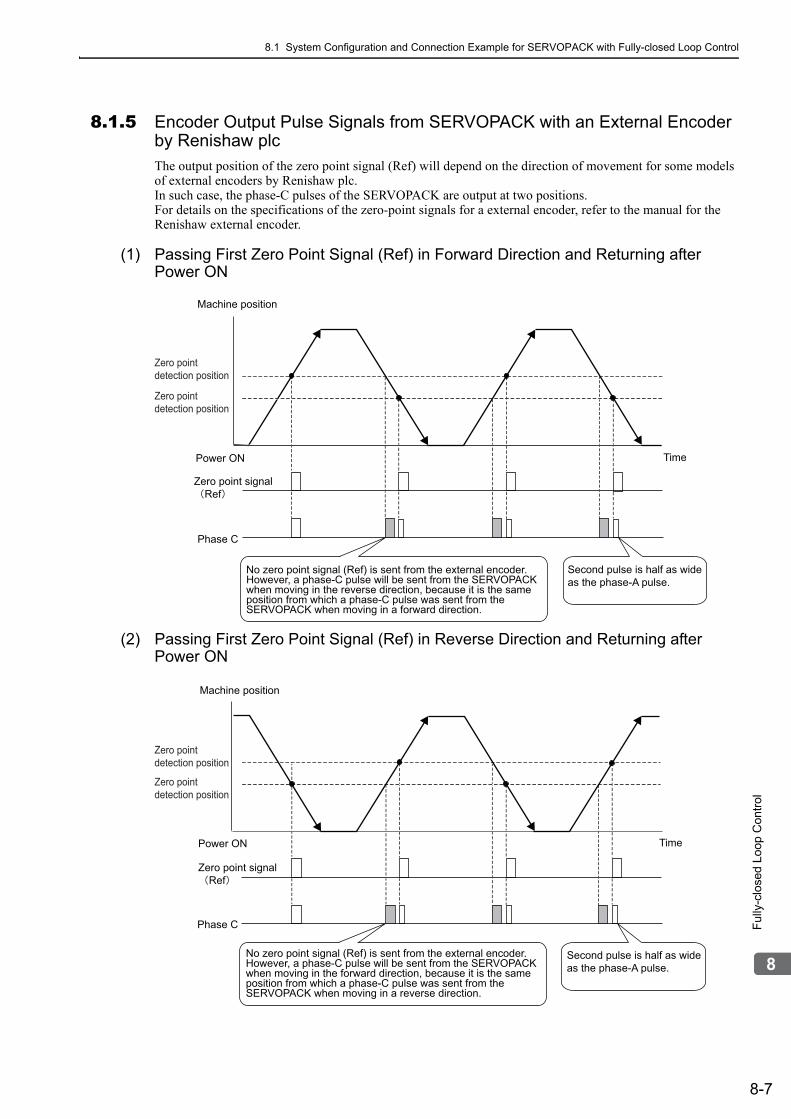
8.1 System Configuration and Connection Example for SERVOPACK with Fully-closed Loop Control
8-7
8
Ful
ly-c
lose
d Lo
op C
ontr
ol
8.1.5 Encoder Output Pulse Signals from SERVOPACK with an External Encoder by Renishaw plcThe output position of the zero point signal (Ref) will depend on the direction of movement for some models of external encoders by Renishaw plc.In such case, the phase-C pulses of the SERVOPACK are output at two positions.For details on the specifications of the zero-point signals for a external encoder, refer to the manual for the Renishaw external encoder.
(1) Passing First Zero Point Signal (Ref) in Forward Direction and Returning after Power ON
(2) Passing First Zero Point Signal (Ref) in Reverse Direction and Returning after Power ON
Machine position
Power ON
Zero point signalRef
Phase C
Time
Second pulse is half as wide as the phase-A pulse.
No zero point signal (Ref) is sent from the external encoder.However, a phase-C pulse will be sent from the SERVOPACK when moving in the reverse direction, because it is the same position from which a phase-C pulse was sent from the SERVOPACK when moving in a forward direction.
Zero point detection position
Zero point detection position
Machine position
Power ON
Zero point signalRef
Phase C
Time
Second pulse is half as wide as the phase-A pulse.
No zero point signal (Ref) is sent from the external encoder.However, a phase-C pulse will be sent from the SERVOPACK when moving in the forward direction, because it is the same position from which a phase-C pulse was sent from the SERVOPACK when moving in a reverse direction.
Zero point detection position
Zero point detection position

8 Fully-closed Loop Control
8.1.6 Precautions When Using an External Incremental Encoder by Magnescale
8-8
8.1.6 Precautions When Using an External Incremental Encoder by MagnescaleWhen an external incremental encoder by Magnescale Co., Ltd. is used, the count direction of the encoder determines if an encoder dividing phase-C pulse (CN1-21, CN1-22) is output and counted.
Note: The count direction (counting up or down) of the encoder determines if a phase-C pulse is output. The output of the pulse does not depend on the settings of these parameters: Pn000.0 (motor rotational direction) and Pn002.3 (exter-nal encoder usage method).
Passing First Zero Point in Forward Direction and Returning after Power ON
When the zero point detection position is first passed in the forward direction after turning the power supply OFF and ON again, the encoder dividing phase-C pulse (CN1-21, CN1-22) is output. Then the encoder divid-ing phase-C pulse is output when the zero point detection position is passed in either the forward or reverse direction.
Model Interpolator Scale pitch (μm)
SL710
PL101-RY
800
SL720 800
SL730 800
SR75 80
SR85 80
Scale count-up direction
Zero point detection position
Power ON Time
Phase-C pulse output
The phase-C pulse is also output when the detection head of the encoder passes this point in reverse, because the SERVOPACK has recorded the position where the phase-C pulse was originally output when first passing the position in the forward direction.

8.1 System Configuration and Connection Example for SERVOPACK with Fully-closed Loop Control
8-9
8
Ful
ly-c
lose
d Lo
op C
ontr
ol
Passing First Zero Point in Reverse Direction and Returning after Power ON
When the zero point detection position is first passed in the reverse direction after turning the power supply OFF and ON again, the encoder dividing phase-C pulse (CN1-21, CN1-22) is not output.However, after the zero point detection position is passed in the forward direction and the encoder dividing phase-C pulse is output, the encoder dividing phase-C pulse is output even when the zero point detection posi-tion is passed in the reverse direction.
External Encoder with Multiple Zero Points and Passing First Zero Point in Forward Direction and Returning after Power ON
When you use an external encoder with multiple zero points, each zero point operates in the same manner as described in 9.1.6 Passing First Zero Point in Forward Direction and Returning after Power ON.
The phase-C pulse is not output when passing the detection position in reverse direction first.
The phase-C pulse is also output when passing this point in reverse, because the SERVOPACK has recorded the position where the phase-C pulse was originally output when first passing the position in the forward direction.
Scale count-up direction
Zero point detection position
Power ON Time
Phase-C pulse output
Zero point 1 detection position
Zero point 2 detection position
Even after zero point 1 has first been passed in the forward direction, the phase-C pulse is not output here because zero point 2 is passed in reverse direction.
The phase-C pulse is also output when passing this point in reverse, because the SERVOPACK has recorded the position where the phase-C pulse was originally output when first passing the position in the forward direction.
Scale count-up direction
Power ON Time
Phase-C pulse output Zero point 1 Zero point 1 Zero point 2 Zero point 2

8 Fully-closed Loop Control
8.1.6 Precautions When Using an External Incremental Encoder by Magnescale
8-10
External Encoder with Multiple Zero Points and Passing First Zero Point in Reverse Direction after Power ON
When you use an external encoder with multiple zero points, each zero point operates in the same manner as described in 9.1.6 Passing First Zero Point in Reverse Direction and Returning after Power ON.
To output the encoder dividing phase-C pulse when moving in the reverse direction, set Pn081 to n.1.
<NOTE>The encoder output pulse is output in the forward and reverse directions regardless of the setting of Pn081 when a serial converter unit is used.
Parameter Meaning When Enabled Classification
Pn081
n.0[Factory Setting]
Outputs phase-C pulse only in forward direction.
After restart Setup
n.1 Outputs phase-C pulse in forward and reverse direction.
Zero point 1 detection position
Zero point 3 detection position
Zero point 2 detection position
Scale count-up direction
Power ON Time
Phase-C pulse output
Zero point 1 Zero point 3Zero point 2Zero point 2Zero point 2
Phase-C pulse is not output when passing a zero point in reverse direction.
Zero point 3

8.1 System Configuration and Connection Example for SERVOPACK with Fully-closed Loop Control
8-11
8
Ful
ly-c
lose
d Lo
op C
ontr
ol
Setting of Pn081.0
Do not change the factory setting if the zero point position of the existing equipment must remain as is.
• When Pn081 is set to n.1, the encoder output phase-C pulse output width may be narrower than the width of the phase-A pulse.
• As shown in the following diagram, there is a 1/8th scale pitch difference in the encoder dividing phase-C pulse output position, the zero point return command, and the phase-C detection position with the phase-C latch when Pn081 is set to n.0 and when Pn081 is set to n.1.
Pn081 = n.0
Pn081 = n.1
1/8 scale pitch
Zero point
Zero point
Moves to forward
1 scale pitch

8 Fully-closed Loop Control
8-12
8.2 SERVOPACK Startup ProcedureFirst check that the SERVOPACK operates correctly with semi-closed loop control, then check that it operates correctly with fully-closed loop control.The following describes the startup procedure for the SERVOPACK in fully-closed loop control.
Procedure Description Operation Parameters Requiring Settings Controller
1
Check operation of the whole sequence in semi-closed loop control and without any load.
Items to Check • Power supply circuit wiring • Servomotor wiring• Encoder wiring• Wiring of I/O signal lines
from the host controller• Servomotor rotation direction,
speed, and number of rota-tions
• Operation of safety mecha-nisms, such as the brakes and the overtravel mechanism
Set the parameters so that the SER-VOPACK operates correctly in semi-closed loop control (Pn002.3 = 0) without any load and check the following points.
• Is there an error with the SER-VOPACK?
• Does the JOG operation operate correctly when operating the SERVOPACK in standalone mode?
• Do the I/O signals turn ON/OFF correctly?
• Does the servomotor turn ON when the SV_ON command is sent from the host controller?
• Does the servomotor operate correctly when the position ref-erence is input by the host con-troller?
• Basic Function Select Switch 0 (Pn000)
• Application Function Select Switch 1 (Pn001)
• External Encoder Usage (Pn002.3)
• Electronic Gear Ratio (Numerator) (Pn20E)
• Electronic Gear Ratio (Denominator) (Pn210)
• Input Signal Selection (Pn50A, Pn50B, Pn511)
• Output Signal Selection (Pn50E, Pn50F, Pn510)
SERVOPACK or host controller
2
Check operation of the system connected with the machine and servomotor in semi-closed loop control mode.
Items to Check • Initial responsiveness of the
system connected with the machine
• Movement direction, distance, and speed of the machine specified by the host control-ler
Connect the servomotor to the machine.Set the moment of inertia ratio (Pn103) using the advanced auto-tuning function.Check that the machine operates in the correct direction, distance, and speed as directed by the host con-troller.
• Moment of inertia ratio (Pn103)
Host controller
3
Check the external encoder.
Item to Check• Are signals from the external
encoder received correctly?
Set parameters related to the fully-closed loop control and move the machine with your hand without turning ON the power supply to the servomotor. Check the following status with the panel operator, digi-tal operator, or SigmaWin+.
• Does the fully-closed feedback pulse counter (Un00E) count up when the servomotor moves in the forward direction?
• Is the distance the machine moved about visually the same as the amount counted by the fully-closed feedback pulse counter (Un00E)?
Note:The unit for fully-closed feedback pulse counter (Un00E) is the exter-nal encoder resolution.Refer to 8.3.5 Electronic Gear for details on the external encoder res-olution.
• External Encoder Usage (Pn002.3)
• Number of External Scale Pitch (Pn20A)
• Electronic Gear Ratio (Numerator) (Pn20E)
• Electronic Gear Ratio (Denominator) (Pn210)
• Encoder Output Resolution (Pn281)
• Excessive Error Level Between Servomotor and Load Positions (Pn51B)
• Positioning Completed Width (Pn522)
• Multiplier per One Fully-closed Rotation (Pn52A)
−

8.2 SERVOPACK Startup Procedure
8-13
8
Ful
ly-c
lose
d Lo
op C
ontr
ol
4
Perform a program JOG opera-tion.
Items to Check• Does the fully-closed loop
control operate correctly when operating the SERVO-PACK in standalone mode?
Perform a program JOG operation and check that the distance that the servomotor moved is the same as the distance that is set in Pn531.Note:Start from a low speed and gradu-ally increase the speed.
• Program JOG related parameters (Pn530 to Pn536)
SERVOPACK
5
Operate the SERVOPACK.
Items to Check • Does the fully-closed loop
control operate correctly including the host controller?
Input the position reference and check that the SERVOPACK oper-ates correctly.Note:Start from a low speed and gradu-ally increase the speed.
− Host controller
(cont’d)
Procedure Description Operation Parameters Requiring Settings
Controller

8 Fully-closed Loop Control
8-14
8.3 Parameter Settings for Fully-closed Loop ControlThis section describes the parameter settings for fully-closed loop control.
Note: When using an external absolute encoder, this external encoder works as an absolute encoder even if Pn002.2 is set to 1.
Set Parameters Setting Contents Position Control
Speed Control
Torque Control
Reference
Pn000.0 Motor rotation direction 8.3.1
Pn002.3 External encoder usage method
Pn20A Number of pitches for the external encoder
8.3.2
Pn281Number of encoder output pulses (PAO, PBO, and PCO) from the SERVOPACK
8.3.3
− External absolute encoder data reception sequence
8.3.4
Pn20E, Pn210 Electronic gear ratio − − 8.3.5
Pn51B Excessive error level between servo-motor and load positions − −
8.3.6
Pn52AMultiplier per one fully-closed rota-tion − −
Pn006/Pn007 Analog monitor signal 8.3.7
Pn22A Speed feedback method during fully-closed loop control
− − 8.3.8
Parameter MeaningWhen
Enabled Classification
Pn002n.0 [Factory setting]
Uses the absolute encoder as an absolute encoder.After restart Setup
n.1 Uses the absolute encoder as an incremental encoder.
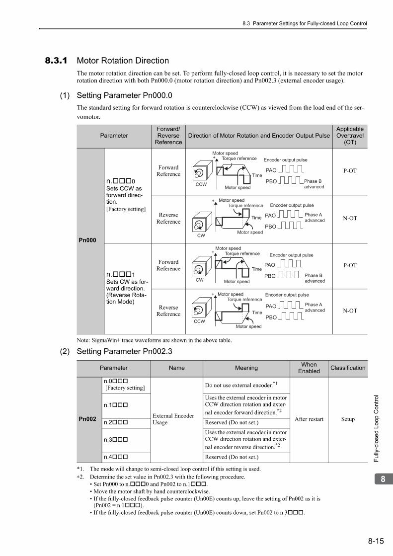
8.3 Parameter Settings for Fully-closed Loop Control
8-15
8
Ful
ly-c
lose
d Lo
op C
ontr
ol
8.3.1 Motor Rotation DirectionThe motor rotation direction can be set. To perform fully-closed loop control, it is necessary to set the motor rotation direction with both Pn000.0 (motor rotation direction) and Pn002.3 (external encoder usage).
(1) Setting Parameter Pn000.0
The standard setting for forward rotation is counterclockwise (CCW) as viewed from the load end of the ser-
vomotor.
Note: SigmaWin+ trace waveforms are shown in the above table.
(2) Setting Parameter Pn002.3
*1. The mode will change to semi-closed loop control if this setting is used.∗2. Determine the set value in Pn002.3 with the following procedure.
• Set Pn000 to n.0 and Pn002 to n.1.• Move the motor shaft by hand counterclockwise.• If the fully-closed feedback pulse counter (Un00E) counts up, leave the setting of Pn002 as it is
(Pn002 = n.1).• If the fully-closed feedback pulse counter (Un00E) counts down, set Pn002 to n.3.
ParameterForward/Reverse
ReferenceDirection of Motor Rotation and Encoder Output Pulse
Applicable Overtravel
(OT)
Pn000
n.0Sets CCW as forward direc-tion. [Factory setting]
Forward Reference
P-OT
Reverse Reference
N-OT
n.1Sets CW as for-ward direction. (Reverse Rota-tion Mode)
Forward Reference P-OT
Reverse Reference
N-OT
PAO
PBO
+
CCW Phase B advanced
Time
Encoder output pulse Motor speed
Torque reference
Motor speed
PAO
PBO
+
CW
Phase A advanced Time
Encoder output pulse Motor speed
Torque reference
Motor speed
PAO
PBO
+
CWPhase B advanced
Time
Encoder output pulse Motor speed
Torque reference
Motor speed
PAO
PBO
+
CCW
Phase A advanced
Encoder output pulse Motor speedTorque reference
Motor speed
Time
Parameter Name Meaning When Enabled
Classification
Pn002
n.0 [Factory setting]
External Encoder Usage
Do not use external encoder.*1
After restart Setup
n.1Uses the external encoder in motor CCW direction rotation and exter-nal encoder forward direction.*2
n.2 Reserved (Do not set.)
n.3Uses the external encoder in motor CCW direction rotation and exter-nal encoder reverse direction.*2
n.4 Reserved (Do not set.)

8 Fully-closed Loop Control
8.3.1 Motor Rotation Direction
8-16
(3) Relation between Motor Rotation Direction and External Encoder Pulse Phases
Refer to the table below.
• The output pulses are phase-B advanced if the motor is turning forward regardless of the setting in Pn000.0.
ParameterPn002.3 (External Encoder Usage)
1 3
Pn000.0(Motorrotationdirection)
0
Reference direction
Forward reference
Reverse reference
Forwardreference
Reverse reference
Motor rotation direction
CCW CW CCW CW
External encoder output
cos lead sin lead sin lead cos lead
Encoder output pulse Phase B lead
Phase Alead
Phase Blead
Phase Alead
1
Reference direction
Forward reference
Reverse reference
Forward reference
Reverse reference
Motor rotation direction
CW CCW CW CCW
External encoderoutput sin lead cos lead cos lead sin lead
Encoder output pulsePhase B
leadPhase A
leadPhase B
leadPhase A
lead

8.3 Parameter Settings for Fully-closed Loop Control
8-17
8
Ful
ly-c
lose
d Lo
op C
ontr
ol
8.3.2 Sine Wave Pitch (Frequency) for an External EncoderSet the number of external encoder pitches per motor rotation to Pn20A.
(1) Setting Example
If the external encoder is connected directly to the motor, the set value will be 1500 (30 mm/0.02 mm = 1500).
Note 1. If there is a fraction, round off the digits below the decimal point.2. If the number of external encoder pitches per motor rotation is not an integer, there will be deviation in the posi-
tion loop gain (Kp), feedforward, and position reference speed monitor. There is no effect on the positioning accuracy.
(2) Related Parameter
8.3.3 Setting Encoder Output Pulses (PAO, PBO, and PCO)Set the position resolution to Pn281. Set the number of phase A and phase B edges.
(1) Setting Example
If the output of a single pulse (multiplied by 4) is 1 μm, the set value will be 20.
If the output of a single pulse (multiplied by 4) is 0.5 μm, the set value will be 40.
The encoder output pulse will have the following waveform if the set value is 20.
"↑" shows the edge position. In this example, the set value is 20 therefore the number of ↑ is 20.
Note: The upper limit of the encoder signal output frequency (multiplied by 4) is 6.4 Mpps. Do not set a value that would cause the output to exceed 6.4 Mpps. If the output exceeds the upper limit, the overspeed of encoder output pulse rate alarm (A.511) will be output.
Example:The frequency is as follows if the set value is 20 and the speed is 1600 mm/s:
= 1600000 = 1.6 Mpps
Because 1.6 Mpps is less than 6.4 Mpps, this value can be used.
SpecificationsExternal encoder sine wave pitch: 20 μmBall screw lead: 30 mm
Pn20A
Number of External Scale Pitch Classifica-tion
Setting Range Setting Unit Factory Setting When Enabled
4 to 1048576 1 pitch/rev 32768 After restart Setup
Position
SpecificationsExternal encoder sine wave pitch: 20 μmBall screw lead: 30 mmSpeed: 1600 mm/s
Phase A
Phase B
Sine wave pitch
1600 mm/s0.001 mm

8 Fully-closed Loop Control
8.3.4 External Absolute Encoder Data Reception Sequence
8-18
(2) Related Parameter
Note: The maximum setting for the encoder output resolution is 4096. When the number of divisions on the external encoder is more than 4096, the data shown in 8.3.5 External Encoder Sine Wave Pitch and Number of Divisions is no longer applicable.
(3) Phase-C Pulse Output Specifications
The pulse width of phase C (origin pulse) varies according to the encoder output resolution (Pn281), and will become the same as the pulse width of phase A.
Output timing for the phase-C pulse is one of the following.
• In synchronization with the phase-A rising edge• In synchronization with the phase-A falling edge• In synchronization with the phase-B rising edge• In synchronization with the phase-B falling edge
8.3.4 External Absolute Encoder Data Reception SequenceThe sequence in which the SERVOPACK receives outputs from the external absolute encoder and transmits them to host controller in fully-closed loop control is shown below.
(1) Outline of Absolute Signals
The serial data, pulses, etc., of the external absolute encoder that are output from the SERVOPACK are output from the PAO, PBO, and PCO signals as shown below.
Note: When host controller receives the data from the external absolute encoder, do not perform counter reset using the output of PCO signal.
Pn281
Encoder Output Resolution Classifica-tion
Setting Range Setting Unit Factory Setting When Enabled
1 to 4096 1 edge/pitch 20 After restart Setup
Position
Phase C of the rotational external absolute encoder is output only at the encoder’s first point of origin after the power is supplied. Phase C of the external encoder is not output every rotation.
Signal Name Status Contents
PAOAt initialization
Serial dataInitial incremental pulses
Normal Operations Incremental pulses
PBOAt initialization Initial incremental pulses
Normal Operations Incremental pulses
PCO Always Origin pulses
CN31 CN1
PAO
PBO
PCO
SerialdataExternal
encoder Serial data→pulse conversion
HostcontrollerSERVOPACK with Fully-closed Module
Dividingcircuit
(Pn281)

8.3 Parameter Settings for Fully-closed Loop Control
8-19
8
Ful
ly-c
lose
d Lo
op C
ontr
ol
(2) Absolute Data Transmission Sequence and Contents
1. Send the Turn Encoder Power Supply ON (SENS_ON) command from the host controller.
2. After 100 ms, set the system to serial data reception-waiting-state. Clear the incremental pulse up/down counter to zero.
3. Receive eight characters of serial data.
4. The system enters a normal incremental operation state about 400 ms after the last serial data is received.
Serial data:The current position pulses divided by Pn281 are output in serial data.One serial data is a value equivalent to 1048576 pulses.
Initial incremental pulses:The current position pulses divided by Pn281 are output in pulses. The number of output pulses is between 0 to 1048576, and the output speed is approximately 1.48 µs per pulse.
Final absolute data PM is calculated by following formula.
PE=MO× R+PO
PM=PE–MS×R–PS
Note: If host controller receives the data from the external absolute encoder, do not perform counter reset using the output of PCO signal.
SENS_ON(Turn Encoder Power Supply ON)
PAO
PBO
Incremental pulses
Incremental pulsesUndefined
Undefined(Phase A) (Phase A)
(Phase B) (Phase B)
Serial data
400 ms max.50 ms
1 to 3 ms
About 15 ms
90 ms typ.60 ms min.
Initialincremental pulses
Initialincremental pulses
0 1 2 3
3 (Mo) 2 0 1 (MS)
PE PM PS MS × R
Mo × R PO
Coordinatevalue
Values of Mo and Ms
Reference position (at setup) Current position
Signal Meaning
PE Current position of external encoder
MO Serial data of current position
PO Number of initial incremental pulses of current position
MS Serial data of reference position
PS Number of initial incremental pulses of reference position
PM Current value required for the user’s system
R 1048576

8 Fully-closed Loop Control
8.3.4 External Absolute Encoder Data Reception Sequence
8-20
(3) Serial Data Specifications
The serial data is output from the PAO signal.
(4) Transferring Alarm Contents
If an external absolute encoder is used, the contents of alarms detected by the SERVOPACK are transmitted in serial data to the host controller from the PAO output when the Turn Encoder Power Supply OFF command (SENS_OFF) is received.
Note: The Turn Encoder Power Supply OFF command (SENS_OFF) cannot be received while the servomotor power is ON.
Output example of alarm contents are as shown below.
Data Transfer Method
Start-stop Synchronization (ASYNC)
Baud rate 9600 bps
Start bits 1 bit
Stop bits 1 bit
Parity Even
Character code ASCII 7-bit code
Data format 8 characters, as shown below.
Note: 1. Data is "P+00000" (CR) or "P-00000" (CR) when the position is zero.2. The serial data range is "-32768" to "+32767". When this range is exceeded, the data
changes from "+32767" to "-32678" or from "-32768" to "+32767." When changing multiturn limit, the range changes. For details, refer to 4.7.6 Multiturn Limit Setting.
DataStart bit Even parity
serial datain five digits
"+" or " - ""0" to "9"
"CR""P"
Stop bit
0 0 0 0 0 1 0 1 0 1
“A” “L” “M” “5” “1” “.” “CR”
Encoder powersupply OFF
High levelEncoder power supply ON
Incremental pulse Serial Data Enlarged view
Turn Encoder Power Supply OFF(SENS_OFF)
Panel Display
PAO Output Data Format
Upper 2 digits
Error detection
or
Overspeed

8.3 Parameter Settings for Fully-closed Loop Control
8-21
8
Ful
ly-c
lose
d Lo
op C
ontr
ol
8.3.5 Electronic GearRefer to 4.4.3 Electronic Gear for the purpose of setting the electronic gear.The following formula is used to calculate the electronic gear ratio in fully-closed loop control.
Note: Set Pn20E (numerator B) and Pn210 (denominator A) to integral values.
The setting range is defined by 0.001 ≤ ≤ 4000.
The following table shows the various external encoder sin wave pitches and the number of divisions.
External Encoder Sine Wave Pitch and Number of Divisions
The sine wave pitches and numbers of divisions for the external encoders are given in the following table.
Calculate the electronic gear ratio with the values in the following table.
∗1. If you use the encoder pulse output with these external encoders, the setting range of the encoder output resolution (Pn281) is restricted. For details, refer to 8.3.3 Setting Encoder Output Pulses (PAO, PBO, and PCO).
∗2. Ask your Mitutoyo Corporation representative for details on this external encoder.∗3. This is the model of rotational external encoder.
Refer to the manuals for the external encoder and serial converter unit for details on the sine wave pitch and the number of divisions of the external encoder.
A
B
Pn210
Pn20E
External encoder sine wave pitch (value in the following table)
Travel distance per reference unit × Number of divisions (value in the following table)Electronic gear ratio == =
B
A
Type of External Encoder
Manufacturer External Encoder Model
Sine Wave Pitch [μm]
Model of Relay Device between
SERVOPACK and External Encoder
Num-ber of Divi-sions
Resolu-tion
Incremen-tal
HeidenhainLIDA48 20 JZDP-D003-000-E 256 0.078 μm
LIF48 4 JZDP-D003-000-E 256 0.016 μm
Renishaw plc RGH22B 20 JZDP-D005-000-E 256 0.078 μm
Magnescale Co., Ltd.
SR75-LF*1 80 – 81920.0098
μm
SR75-MF 80 – 1024 0.078 μm
SR85-LF*1 80 – 8192 0.0098 μm
SR85-MF 80 – 1024 0.078 μm
SL700*1, SL710*1, SL720*1, SL730*1 800 PL101-RY 8192 0.0977
μm
Absolute
Heidenhain LIC4100 20.48 EIB3391Y 4096 0.005 μm
Mitutoyo Corporation
ST781A/ST781AL 256 – 512 0.5 μm
ST782A/ST782AL 256 – 512 0.5 μm
ST783/ST783AL 51.2 – 512 0.1 μm
ST784/ST784AL 51.2 – 512 0.1 μm
ST788A/ST788AL 51.2 – 512 0.1 μm
ST789A/ST789AL*2 25.6 – 512 0.05 μm
Magnescale Co., Ltd.
SR77-LF*1 80 – 8192 0.0098 μm
SR77-MF 80 – 1024 0.078 μm
SR87-LF*1 80 – 81920.0098
μm
SR87-MF 80 – 1024 0.078 μm
RU77-4096ADF*3 – – 256 20 bits
RU77-4096AFFT01*3 – – 1024 22 bits

8 Fully-closed Loop Control
8.3.6 Alarm Detection
8-22
Setting Example
A setting example is given below.
If the servomotor moves 0.2 μm for every pulse of position reference, the external encoder sine wave pitch is 20 μm, and the number of divisions is 256, the electronic gear ratio will be as follow.
Therefore, set 512 for Pn20E (numerator B) and 200 for Pn210 (denominator A).
8.3.6 Alarm DetectionThe setting of alarm detection (Pn51B/Pn52A) is shown below.
(1) Excessive Error Level between Servomotor and Load Positions (Pn51B)
This setting detects the difference between the feedback position of the motor encoder and the feedback load position of the external encoder in fully-closed loop control. If the detected difference is above the set level, the motor-load position error overflow alarm (A.d10) will be output.
Note: When Pn51B is set to 0, the motor-load position error overflow alarm (A.d10) is not detected.
(2) Multiplier per One Fully-closed Rotation (Pn52A)
The coefficient of the error between the external encoder and the motor per motor rotation can be set. This function can be used to prevent the motor from running out of control due to damage to the external encoder or to detect slippage of the belt.
Setting Example
Increase the value if the belt slips or is twisted excessively.
If the set value is 0, the external encoder value will be read as it is.If the factory setting of 20 is used, the second rotation will start with the error for the first motor rotation mul-tiplied by 0.8. (Refer to the following figure.)
A
B
Pn210
Pn20E
20
0.2 × 256== =Electronic gear ratio
200
512==
Pn51B
Excessive Error Level between Servomotor and Load Positions Classifica-
tionSetting Range Setting Unit Factory Setting When Enabled
0 to 1073741824 1 reference unit 1000 Immediately Setup
Position
Pn52A=0
Pn52A=100
Pn52A=20
1strotation
2ndrotation
Number of motor rotations
Error between motor and external encoder
3rdrotation
Less thanone rotation
Small
Big

8.3 Parameter Settings for Fully-closed Loop Control
8-23
8
Ful
ly-c
lose
d Lo
op C
ontr
ol
Related Parameter
8.3.7 Analog Monitor SignalThe position error between servomotor and load can be monitored with the analog monitor.
8.3.8 Speed Feedback Method during Fully-closed Loop Control
Use Pn22A.3 to select the speed feedback method during fully-closed loop control: Normally, set Pn22A.3 to 0 (Uses motor encoder speed.). Set Pn22A.3 to 1 (Uses external encoder speed.) when connecting a direct drive motor and high-resolution external encoder.
Note: This parameter cannot be used when Pn002.3 is set to 0.
Pn52A
Multiplier per One Fully-closed Rotation Classifica-tion
Setting Range Setting Unit Factory Setting When Enabled
0 to 100 1% 20 Immediately Setup
Position
Parameter Name Meaning When Enabled Classification
Pn006 n.07Analog Monitor 1 Signal Selection
Position error between servomotor and load[0.01 V/1 reference unit](Factory setting: n.02)
Immediately Setup
Pn007 n.07 Analog Monitor 2 Signal Selection
Position error between servomotor and load[0.01 V/1 reference unit](Factory setting: n.00)
Parameter Meaning When Enabled Classification
Pn22An.0[Factory setting] Uses motor encoder speed.
After restart Setup
n.1 Uses external encoder speed.
Position reference
MECHATROLINK Speed reference
ENC
A.d10
Pn22A
MECHATROLINK 1monitor data
Speed conversion
Unit conversionPn20A
Elec-tronicgear
Electronicgear
Encoder outputpulse
Error counter
Speedloop
Alarmdetection
Divider
MachinePositioncontrol loop
Serialconversion
Motor
External encoderSpeed conversion
Speed feedback
SERVOPACK

9-1
9
Tro
uble
sho
otin
g
9Troubleshooting
9.1 Alarm Displays . . . . . . . . . . . . . . . . . . . . . . . . . . . . . . . . . . . . . . . . . . . . . .9-29.1.1 List of Alarms . . . . . . . . . . . . . . . . . . . . . . . . . . . . . . . . . . . . . . . . . . . . . . . . . . . . . . . . 9-29.1.2 Troubleshooting of Alarms . . . . . . . . . . . . . . . . . . . . . . . . . . . . . . . . . . . . . . . . . . . . . . 9-6
9.2 Warning Displays . . . . . . . . . . . . . . . . . . . . . . . . . . . . . . . . . . . . . . . . . . .9-239.2.1 List of Warnings . . . . . . . . . . . . . . . . . . . . . . . . . . . . . . . . . . . . . . . . . . . . . . . . . . . . . 9-239.2.2 Troubleshooting of Warnings . . . . . . . . . . . . . . . . . . . . . . . . . . . . . . . . . . . . . . . . . . . 9-24
9.3 Monitoring Communication Data on Occurrence of an Alarm or Warning . . . . . . . . . . . . . . . . . . . . . . . . . . . . . . . . . . . . . . . . . . . . . . . 9-28
9.4 Troubleshooting Malfunction Based on Operation and Conditions of the Servomotor . . . . . . . . . . . . . . . . . . . . . . . . . . . . . . . . .9-29

9 Troubleshooting
9.1.1 List of Alarms
9-2
9.1 Alarm DisplaysThe following sections describe troubleshooting in response to alarm displays.
The alarm name, alarm meaning, alarm stopping method, and alarm reset capability are listed in order of the alarm numbers in 9.1.1 List of Alarms.
The causes of alarms and troubleshooting methods are provided in 9.1.2 Troubleshooting of Alarms.
9.1.1 List of AlarmsThis section provides list of alarms.
Servomotor Stopping Method
If an alarm occurs, the servomotor can be stopped by doing either of the following operations.
Gr.1: The servomotor is stopped according to the setting in Pn001.0 if an alarm occurs. Pn001.0 is factory-set to stop the servomotor by applying the DB.
Gr.2: The servomotor is stopped according to the setting in Pn00B.1 if an alarm occurs. Pn00B.1 is factory-set to stop the servomotor by setting the speed reference to "0." The servomotor under torque control will always use the Gr.1 method to stop. By setting Pn00B.1 to 1, the servomotor stops using the same method as Gr.1. When coordinating a number of servomotors, use this stopping method to prevent machine damage that may result due to differences in the stop method.
Alarm Reset
Available:Removing the cause of alarm and then executing the alarm reset can clear the alarm. N/A:Executing the alarm reset cannot clear the alarm.
Alarm Number Alarm Name Meaning
Servo-motor
Stopping Method
Alarm Reset
A.020 Parameter Checksum Error 1
The data of the parameter in the SERVOPACK is incorrect.
Gr.1 N/A
A.021 Parameter Format Error 1 The data of the parameter in the SERVOPACK is incorrect. Gr.1 N/A
A.022 System Checksum Error 1The data of the parameter in the SERVOPACK is incorrect. Gr.1 N/A
A.030 Main Circuit Detector Error Detection data for main circuit is incorrect. Gr.1 Available
A.040 Parameter Setting Error 1 The parameter setting is outside the setting range. Gr.1 N/A
A.041 Encoder Output Pulse Setting Error
The encoder output pulse (Pn212) is outside the set-ting range or does not satisfy the setting conditions.
Gr.1 N/A
A.042 Parameter Combination Er-ror
Combination of some parameters exceeds the setting range. Gr.1 N/A
A.044Semi-closed/Fully-closed Loop Control Parameter Setting Error
The setting in the fully-closed option module and the setting in Pn002.3 do not match. Gr.1 N/A
A.04A Parameter Setting Error 2 Bank member/bank data setting is incorrect. Gr.1 N/A
A.050 Combination Error The SERVOPACK and the servomotor capacities do not match each other. Gr.1 Available
A.051 Unsupported Device Alarm The device unsupported was connected. Gr.1 N/A
A.0b0 Canceled Servo ON Command Alarm
The servo ON command (SV_ON) was sent from the host controller after executing a utility function that turns ON servomotor.
Gr.1 Available
A.100 Overcurrent or Heat Sink Overheated
An overcurrent flowed through the IGBT or the heat sink of the SERVOPACK was overheated. Gr.1 N/A
A.300 Regeneration ErrorRegenerative circuit or regenerative resistor is faulty. Gr.1 Available
A.320 Regenerative Overload Regenerative energy exceeds regenerative resistor capacity.
Gr.2 Available

9.1 Alarm Displays
9-3
9
Tro
uble
sho
otin
g
A.330 Main Circuit Power Supply Wiring Error
• Setting of AC input/DC input is incorrect.• Power supply wiring is incorrect.
Gr.1 Available
A.400 Overvoltage Main circuit DC voltage is excessively high. Gr.1 Available
A.410 Undervoltage Main circuit DC voltage is excessively low. Gr.2 Available
A.450 Main-Circuit Capacitor Overvoltage
The capacitor of the main circuit has deteriorated or is faulty. Gr.1 N/A
A.510 Overspeed The servomotor speed is above the maximum rota-tional speed.
Gr.1 Available
A.511 Overspeed of Encoder Out-put Pulse Rate
The pulse output speed upper limit of the set encoder output pulse (Pn212) is exceeded. Gr.1 Available
A.520 Vibration Alarm Incorrect vibration at the motor speed was detected. Gr.1 Available
A.521 Autotuning AlarmVibration was detected while performing tuning-less function. Gr.1 Available
A.710 Overload: High LoadThe servomotor was operating for several seconds to several tens of seconds under a torque largely exceeding ratings.
Gr.2 Available
A.720 Overload: Low Load The servomotor was operating continuously under a torque exceeding ratings. Gr.1 Available
A.730A.731 Dynamic Brake Overload
When the dynamic brake was applied, rotational energy exceeded the capacity of dynamic brake resistor.
Gr.1 Available
A.740 Overload of Surge Current Limit Resistor
The main circuit power was frequently turned ON and OFF. Gr.1 Available
A.7A0 Heat Sink Overheated The heat sink of the SERVOPACK exceeded 100°C. Gr.2 Available
A.7Ab Built-in Fan in SERVOPACK Stopped The fan inside the SERVOPACK stopped. Gr.1 Available
A.810 Encoder Backup Error The power supplies to the encoder all failed and position data was lost.
Gr.1 N/A
A.820 Encoder Checksum Error The checksum results of encoder memory is incor-rect. Gr.1 N/A
A.830 Absolute Encoder Battery Error
The battery voltage was lower than the specified value after the control power supply was turned ON. Gr.1 Available
A.840 Encoder Data Error Data in the encoder is incorrect. Gr.1 N/A
A.850 Encoder Overspeed The encoder was rotating at high speed when the power was turned ON.
Gr.1 N/A
A.860 Encoder Overheated The internal temperature of encoder is too high. Gr.1 N/A
A.8A0 External Encoder Error External encoder is faulty. Gr.1 Available
A.8A1 External Encoder Error of Module Serial converter unit is faulty. Gr.1 Available
A.8A2 External Encoder Error of Sensor External encoder is faulty. Gr.1 Available
A.8A3 External Encoder Error of Position
The position data of external encoder is faulty. Gr.1 Available
A.8A5 External Encoder Over-speed The overspeed from the external encoder occurred. Gr.1 Available
A.8A6 External Encoder Overheat-ed The overheat from the external encoder occurred. Gr.1 Available
A.b31 Current Detection Error 1 The current detection circuit for phase U is faulty. Gr.1 N/A
A.b32 Current Detection Error 2 The current detection circuit for phase V is faulty. Gr.1 N/A
A.b33 Current Detection Error 3 The detection circuit for the current is faulty. Gr.1 N/A
(cont’d)
Alarm Number Alarm Name Meaning
Servo-motor
Stopping Method
Alarm Reset

9 Troubleshooting
9.1.1 List of Alarms
9-4
A.b6AMECHATROLINKCommunicationsASIC Error 1
ASIC error occurred in the MECHATROLINK communications. Gr.1 N/A
A.b6bMECHATROLINKCommunicationsASIC Error 2
ASIC error occurred in the MECHATROLINK communications. Gr.2 N/A
A.bE0 Firmware Error An internal program error occurred in the SERVO-PACK. Gr.1 N/A
A.bF0 System Alarm 0Internal program error 0 occurred in the SERVO-PACK. Gr.1 N/A
A.bF1 System Alarm 1 Internal program error 1 occurred in the SERVO-PACK.
Gr.1 N/A
A.bF2 System Alarm 2 Internal program error 2 occurred in the SERVO-PACK. Gr.1 N/A
A.bF3 System Alarm 3 Internal program error 3 occurred in the SERVO-PACK. Gr.1 N/A
A.bF4 System Alarm 4Internal program error 4 occurred in the SERVO-PACK. Gr.1 N/A
A.C10 Servo Overrun Detected The servomotor ran out of control. Gr.1 Available
A.C80Absolute Encoder Clear Er-ror and Multiturn Limit Set-ting Error
The absolute encoder multiturn data was cleared or the setting is not correct. Gr.1 N/A
A.C90 Encoder Communications Error
Communications between the SERVOPACK and the encoder is not possible. Gr.1 N/A
A.C91 Encoder Communications Position Data Error
An encoder position data calculation error occurred. Gr.1 N/A
A.C92 Encoder Communications Timer Error
An error occurs in the communications timer between the encoder and the SERVOPACK. Gr.1 N/A
A.CA0 Encoder Parameter Error Encoder parameters are faulty. Gr.1 N/A
A.Cb0 Encoder Echoback ErrorContents of communications with encoder are incor-rect. Gr.1 N/A
A.CC0 Multiturn Limit Disagreement
Different multiturn limits have been set in the encoder and the SERVOPACK.
Gr.1 N/A
A.CF1Feedback Option Module Communications Error (Re-ception error)
Reception from the Feedback Option Module is faulty.
Gr.1 N/A
A.CF2Feedback Option Module Communications Error (Tim-er stop)
Timer for communications with the Feedback Option Module is faulty. Gr.1 N/A
A.d00 Position Error OverflowPosition error exceeded the value of excessive posi-tion error alarm level (Pn520) when the servomotor power is ON.
Gr.1 Available
A.d01 Position Error Overflow Alarm at Servo ON
This alarm occurs if the servomotor power is turned ON when the position error is greater than the set value of Pn526 while the servomotor power is OFF.
Gr.1 Available
A.d02Position Error Overflow Alarm by Speed Limit at Ser-vo ON
When the position errors remain in the error counter, Pn529 limits the speed if the servomotor power is turned ON. If Pn529 limits the speed in such a state, this alarm occurs when position references are input and the number of position errors exceeds the value set for the excessive position error alarm level (Pn520).
Gr.2 Available
A.d10 Motor-load Position Error Overflow
During fully-closed loop control, the position error between motor and load is excessive.
Gr.2 Available
(cont’d)
Alarm Number Alarm Name Meaning
Servo-motor
Stopping Method
Alarm Reset

9.1 Alarm Displays
9-5
9
Tro
uble
sho
otin
g
A.E02MECHATROLINKInternal Synchronization Er-ror 1
Synchronization error during MECHATROLINK communications with the SERVOPACK. Gr.1 Available
A.E40MECHATROLINK Transmission Cycle Setting Error
The setting of the MECHATROLINK transmission cycle is out of the allowable range. Gr.2 Available
A.E50 MECHATROLINK Synchronization Error
A synchronization error occurs during MECHA-TROLINK communications. Gr.2 Available
A.E51 MECHATROLINK Synchronization Failed
A synchronization failure occurs in MECHA-TROLINK communications. Gr.2 Available
A.E60MECHATROLINK Communications Error (Re-ception error)
A communications error occurs continuously during MECHATROLINK communications. Gr.2 Available
A.E61MECHATROLINK Transmission Cycle Error (Synchronization interval er-ror)
The transmission cycle fluctuates during MECHA-TROLINK communications. Gr.2 Available
A.E71 Safety Option Module Detection Failure Detection of the safety option module failed. Gr.1 N/A
A.E72 Feedback Option Module Detection Failure Detection of the Feedback Option Module failed. Gr.1 N/A
A.E74 Unsupported Safety Option Module
An unsupported safety option module was con-nected.
Gr.1 N/A
A.E75 Unsupported Feedback Op-tion Module
An unsupported feedback option module was con-nected. Gr.1 N/A
A.E81*1 SERVOPACK: Safety Mod-ule Alarm – – –
A.EA2 DRV Alarm 2 (SERVOPACK WDC error)
A SERVOPACK DRV alarm 0 occurs. Gr.2 Available
A.Eb1 Safety Function Signal Input Timing Error The safety function signal input timing is faulty. Gr.1 N/A
A.Eb*1 SERVOPACK: Safety Mod-
ule Alarms – – –A.EC*1
A.Ed1 Command Execution Timeout
A timeout error occurred when using a MECHA-TROLINK command. Gr.2 Available
A.F10 Main Circuit Cable Open Phase
A low voltage continued for one second or longer in either phase R, S, or T when the main circuit power supply was ON.
Gr.2 Available
A.F50 Servomotor Main Circuit Cable Disconnection
The servomotor did not operate or power was not supplied to the servomotor even though the SV_ON (Servo ON) command was input when the servomotor was ready to receive it.
Gr.1 Available
FL-1*2
System AlarmInternal program error occurred in the SERVO-PACK − N/A
FL-2*2
CPF00 Digital Operator Transmission Error 1 Communications cannot be performed between the
digital operator (model: JUSP-OP05A-1-E) and the SERVOPACK (CPU error or other error).
− N/A
CPF01 Digital Operator Transmission Error 2
∗1. These alarms occur in SERVOPACKs with safety modules. For details, refer to the Σ-V Series AC Servo Drives User's Manual Safety Module (Manual No. SIEP C720829 06).
∗2. These alarms are not saved in the alarm history. There are displayed only on the panel display.
(cont’d)
Alarm Number Alarm Name Meaning
Servo-motor
Stopping Method
Alarm Reset

9 Troubleshooting
9.1.2 Troubleshooting of Alarms
9-6
9.1.2 Troubleshooting of AlarmsIf an error occurs in the servo drive, an alarm A. or CPF is displayed on the panel display.
Refer to the following table to identify the cause of an alarm and the action to be taken.Contact your Yaskawa representative if the problem cannot be solved by the described corrective action.
Alarm Number:Alarm Name Cause Investigative Actions Corrective Actions
A.020:Parameter Checksum Error 1(The parameter data in the SERVOPACK is incorrect.)
The power supply voltage sud-denly dropped. Measure the power supply voltage.
Set the power supply voltage within the specified range, and set Fn005 to initialize the parameter.
The power supply went OFF while changing a parameter set-ting.
Check the circumstances when the power supply went OFF.
Set Fn005 to initialize the parameter and then set the parameter again.
The number of times that parame-ters were written exceeded the limit.
Check to see if the parameters were frequently changed through the host controller.
The SERVOPACK may be faulty. Replace the SERVOPACK.Reconsider the method of writing parameters.
Malfunction caused by noise from the AC power supply or grounding line, static electricity noise, etc.
Turn the power supply to the SER-VOPACK OFF and ON again. If the alarm still occurs, the cause may be noise.
Take countermeasures against noise.
Gas, water drops, or cutting oil entered the SERVOPACK and caused failure of the internal components.
Check the installation conditions. The SERVOPACK may be faulty. Replace the SERVOPACK.
A SERVOPACK fault occurred.
Turn the power supply to the SER-VOPACK OFF and ON again. If the alarm still occurs, the SERVO-PACK may be faulty.
The SERVOPACK may be faulty. Replace the SERVOPACK.
A.021:Parameter Format Error 1(The parameter data in the SERVOPACK is incorrect.)
The software version of SERVO-PACK that caused the alarm is older than that of the written parameter.
Check Fn012 to see if the set soft-ware version agrees with that of the SERVOPACK. If not, an alarm may occur.
Write the parameter of another SERVOPACK of the same model with the same software version. Then turn the power OFF and then ON again.
A SERVOPACK fault occurred. − The SERVOPACK may be faulty. Replace the SERVOPACK.
A.022:System Checksum Error 1(The parameter data in the SERVOPACK is incorrect.)
The power supply voltage sud-denly dropped.
Measure the power supply voltage. The SERVOPACK may be faulty. Replace the SERVOPACK.
The power supply went OFF while setting an utility function.
Check the circumstances when the power supply went OFF.
The SERVOPACK may be faulty. Replace the SERVOPACK.
A SERVOPACK fault occurred.
Turn the power supply to the SER-VOPACK OFF and ON again. If the alarm still occurs, the SERVO-PACK may be faulty.
The SERVOPACK may be faulty. Replace the SERVOPACK.
A.030:Main Circuit Detector Error
A SERVOPACK fault occurred. − The SERVOPACK may be faulty. Replace the SERVOPACK.
A.040:Parameter Setting Error 1(The parameter setting was out of the setting range.)
The SERVOPACK and servomo-tor capacities do not match each other.
Check the combination of SERVO-PACK and servomotor capacities.
Select the proper combination of SERVOPACK and servomotor capacities.
A SERVOPACK fault occurred. − The SERVOPACK may be faulty. Replace the SERVOPACK.
The parameter setting is out of the setting range.
Check the setting ranges of the parameters that have been changed.
Set the parameter to a value within the setting range.
The electronic gear ratio is out of the setting range.
Check the electronic gear ratio. The ratio must satisfy:0.001< (Pn20E/Pn210) < 4000.
Set the electronic gear ratio in the range: 0.001< (Pn20E/Pn210) < 4000.
A.041:Encoder Output Pulse Setting Error
The encoder output pulse (Pn212) is out of the setting range and does not satisfy the setting condi-tions.
Check the parameter Pn212. Set Pn212 to a correct value.

9.1 Alarm Displays
9-7
9
Tro
uble
sho
otin
g
A.042:Parameter Combination Error
The speed of program JOG oper-ation (Fn004) is lower than the setting range after having changed the electronic gear ratio (Pn20E/Pn210) or the servomo-tor.
Check if the detection conditions are satisfied.*1
Decrease the setting of the elec-tronic gear ratio (Pn20E/Pn210).
The speed of program JOG oper-ation (Fn004) is lower than the setting range after having changed the setting of the pro-gram JOG movement speed (Pn533).
Check if the detection conditions are satisfied.*1
Increase the setting of the program JOG movement speed (Pn533).
The moving speed of advanced autotuning is lower than the set-ting range after having changed the electronic gear ratio (Pn20E/Pn210) or the servomotor.
Check if the detection conditions are satisfied.*2
Decrease the setting of the elec-tronic gear ratio (Pn20E/Pn210).
A.044:Semi-closed/Fully-closed Loop Control Parameter Setting Error
The setting of the fully-closed module does not match with that of Pn002.3.
Check the settings of Pn002.3.The setting of fully-closed module must be compatible with the setting of Pn002.3.
A.04A:Parameter Setting Error 2
For a 4-byte parameter bank, no registration in two consecutive bytes for two bank members.
–Change the number of bytes for bank members to an appropriate value.
The total amount of bank data exceeds 64. (Pn900 × Pn901 > 64)
– Reduce the total amount of bank data to 64 or less.
A.050:Combination Error(The SERVOPACK and servomotor capacities do not correspond.)
The SERVOPACK and servomo-tor capacities do not match each other.
Check the capacities to see if they satisfy the following condition: Select the proper combination of
SERVOPACK and servomotor capacities.
An encoder fault occurred.Replace the servomotor and see if the alarm occurs again. Replace the servomotor (encoder).
A SERVOPACK fault occurred. − The SERVOPACK may be faulty. Replace the SERVOPACK.
A.051:Unsupported Device Alarm
An unsupported serial converter unit, encoder, or external encoder is connected to the SERVO-PACK.
Check the product specifications, and select the correct model.
Select the correct combination of units.
A.0b0:Canceled Servo ON Command Alarm
After executing the utility func-tion to turn ON the power to the motor, the servo ON command (SV_ON) was sent from the host controller.
−Turn the SERVOPACK power sup-ply OFF and then ON again or exe-cute a software reset.
∗1. Detection conditionsIf one of the following conditions detected, an alarm occurs.
•
•
∗2. Detection conditionsIf one of the following conditions detected, an alarm occurs.
•
•
(cont’d)
Alarm Number:Alarm Name
Cause Investigative Actions Corrective Actions
≤ Servomotor capacitySERVOPACK capacity
≤ 414
Pn533 [min-1] ×6 × 105
Encoder resolution≤ Pn20E
Pn210
Max Motor Speed [min-1] ×About 3.66 × 10¹²
Encoder resolution≥ Pn20E
Pn210
Rated Motor Speed [min-1] × 1/3 ×6 × 105
Encoder resolution≤ Pn20E
Pn210
Max Motor Speed [min-1] ×About 3.66 × 10¹²
Encoder resolution≥ Pn20E
Pn210

9 Troubleshooting
9.1.2 Troubleshooting of Alarms
9-8
A.100:Overcurrent or Heat Sink Overheated(An overcurrent flowed through the IGBT or heat sink of SERVO-PACK overheated.)
Incorrect wiring or contact fault of main circuit cables.
Check the wiring. Refer to 3.1 Main Circuit Wiring for details.
Correct the wiring.
Short-circuit or ground fault of main circuit cables.
Check for short-circuits across the servomotor terminal phases U, V, and W, or between the grounding and servomotor terminal phases U, V, or W. Refer to 3.1 Main Circuit Wiring for details.
The cable may be short-circuited. Replace the cable.
Short-circuit or ground fault inside the servomotor.
Check for short-circuits across the servomotor terminal phases U, V, and W, or between the grounding and servomotor terminal phases U, V, or W. Refer to 3.1 Main Circuit Wiring for details.
The servomotor may be faulty. Replace the servomotor.
Short-circuit or ground fault inside the SERVOPACK.
Check for short-circuits across the servomotor connection terminals U, V, and W on the SERVOPACK, or between the grounding and terminal U, V, or W. Refer to 3.1 Main Cir-cuit Wiring for details.
The SERVOPACK may be faulty. Replace the SERVOPACK.
Incorrect wiring or contact fault of the regenerative resistor.
Check the wiring. Refer to 3.7 Con-necting Regenerative Resistors for details.
Correct the wiring.
The dynamic brake (DB: Emer-gency stop executed from the SERVOPACK) was frequently activated, or the DB overload alarm occurred.
Check the power consumed by DB resistance (Un00B) to see how many times the DB has been used. Or, check the alarm history display Fn000 to see if the DB overload alarm A.730 or A.731 was reported.
Change the SERVOPACK model, operating conditions, or the mecha-nism so that the DB does not need to be used so frequently.
The generated regenerative resis-tor value exceeded the SERVO-PACK regenerative energy processing capacity.
Check the regenerative load ratio (Un00A) to see how many times the regenerative resistor has been used.
Check the operating condition including overload, and reconsider the regenerative resistor value.
The SERVOPACK regenerative resistance is too small.
Check the regenerative load ratio (Un00A) to see how many times the regenerative resistor has been used.
Change the regenerative resistance value to a value larger than the SERVOPACK minimum allowable resistance value.
A heavy load was applied while the servomotor was stopped or running at a low speed.
Check to see if the operating condi-tions are outside servo drive specifi-cations.
Reduce the load applied to the ser-vomotor or increase the operating speed.
Malfunction caused by noise interference.
Improve the wiring or installation environment, such as by reducing noise, and check to see if the alarm recurs.
Take countermeasures for noise, such as correct wiring of the FG. Use an FG wire size equivalent to the SERVOPACK main circuit wire size.
A SERVOPACK fault occurred. −
Turn the power supply to the SER-VOPACK OFF and ON again. If the alarm still occurs, the SERVO-PACK may be faulty. Replace the SERVOPACK.
(cont’d)
Alarm Number:Alarm Name
Cause Investigative Actions Corrective Actions

9.1 Alarm Displays
9-9
9
Tro
uble
sho
otin
g
A.300:Regeneration Error
The regenerative resistor capacity (Pn600) is set to a value other than 0 for a SGDV-R70F, -R90F, -2R1F, -R70A, -R90A, -1R6A, or -2R8A SERVOPACK, and an external regenerative resistor is not connected.
Check the external regenerative resistor connection and the value of the Pn600.
Connect the external regenerative resistor, or set Pn600 to 0 if no regenerative resistor is required.
An external regenerative resistor is not connected to the SGDV-470A, -550A, -590A, -780A, -210D, -260D, -280D, or -370D SERVOPACK.
Check the connection of the exter-nal regenerative resistor or the Yaskawa regenerative resistor unit and the set value in Pn600.
Connect an external regenerative resistor and set Pn600 to the appro-priate value, or connect a Yaskawa regenerative resistor unit and set Pn600 to 0.
The jumper between the power supply terminals B2 and B3 has been removed for one of these SERVOPACKs: SGDV-3R8A, -5R5A, -7R6A, -120A, -180A, -200A, -330A, -1R9D, -3R5D, -5R4D, -8R4D, -120D, and -170D.
Confirm that a jumper is mounted between the power supply terminals B2 and B3.
Correctly mount a jumper.
The external regenerative resis-tor is incorrectly wired, or is removed or disconnected.
Check the external regenerative resistor connection.
Correctly connect the external regenerative resistor.
A SERVOPACK fault occurred. −
Turn the SERVOPACK’s control power supply OFF and ON again while the main circuit power supply is OFF. If the alarm still occurs, the SERVOPACK may be faulty. Replace the SERVOPACK.
A.320:Regenerative Overload
The power supply voltage exceeds the specified limit. Measure the power supply voltage. Set the power supply voltage within
the specified range.
Insufficient external regenerative resistance, regenerative resistor capacity, or SERVOPACK capac-ity. Or, regenerative power has been continuously flowing back.
Check the operating condition or the capacity using the capacity selection Software SigmaJunma-Size+, etc.
Change the regenerative resistance, regenerative resistor capacity, or SERVOPACK capacity. Reconsider the operating conditions using the capacity selection software Sigma-JunmaSize+, etc.
Regenerative power continu-ously flowed back because nega-tive load was continuously applied.
Check the load applied to the servo-motor during operation.
Reconsider the system including servo, machine, and operating con-ditions.
The setting of parameter Pn600 is smaller than the external regener-ative resistor's capacity.
Check the external regenerative resistor connection and the value of the Pn600.
Set the Pn600 to a correct value.
The external regenerative resis-tance is too high. Check the regenerative resistance.
Change the regenerative resistance to a correct value or use an external regenerative resistor of appropriate capacity.
A SERVOPACK fault occurred. − The SERVOPACK may be faulty. Replace the SERVOPACK.
(cont’d)
Alarm Number:Alarm Name
Cause Investigative Actions Corrective Actions

9 Troubleshooting
9.1.2 Troubleshooting of Alarms
9-10
A.330:Main Circuit Power Supply Wiring Error(Detected when the main circuit power supply is turned ON.)
The regenerative resistor discon-nected when the SERVOPACK power supply voltage was high.
Measure the resistance of the regen-erative resistor using a measuring instrument.
When using a regenerative resistor built in the SERVOPACK:Replace the SERVOPACK.When using an external regenera-tive resistor:Replace the external regenerative resistor.
In the AC power input mode, DC power was supplied.
Check the power supply to see if it is a DC power supply.
Correct the settings to match the actual power supply specifications.
In the DC power input mode, AC power was supplied.
Check the power supply to see if it is an AC power supply.
Correct the settings to match the actual power supply specifications.
The regenerative resistor capacity (Pn600) is set to a value other than 0 for a SGDV-R70F, -R90F, -2R1F, -R70A, -R90A, -1R6A, or -2R8A SERVOPACK, and an external regenerative resistor is not connected.
Check the external regenerative resistor connection and the value of the Pn600.
Connect the external regenerative resistor, or set Pn600 to 0 if no external regenerative resistor is required.
An external regenerative resistor is not connected to the SGDV-470A, -550A, -590A, -780A, -210D, -260D, -280D, or -370D SERVOPACK.
Check the connection of the exter-nal regenerative resistor or the Yaskawa regenerative resistor unit and the set value in Pn600.
Connect an external regenerative resistor and set Pn600 to the appro-priate value, or connect a Yaskawa regenerative resistor unit and set Pn600 to 0.
The jumper between the power supply terminals B2 and B3 has been removed for one of these SERVOPACKs: SGDV-3R8A, -5R5A, -7R6A, -120A, -180A, -200A, -330A, -1R9D, -3R5D, -5R4D, -8R4D, -120D, and -170D.
Confirm that a jumper is mounted between the power supply terminals B2 and B3.
Correctly mount a jumper.
A SERVOPACK fault occurred. − The SERVOPACK may be faulty. Replace the SERVOPACK.
(cont’d)
Alarm Number:Alarm Name
Cause Investigative Actions Corrective Actions
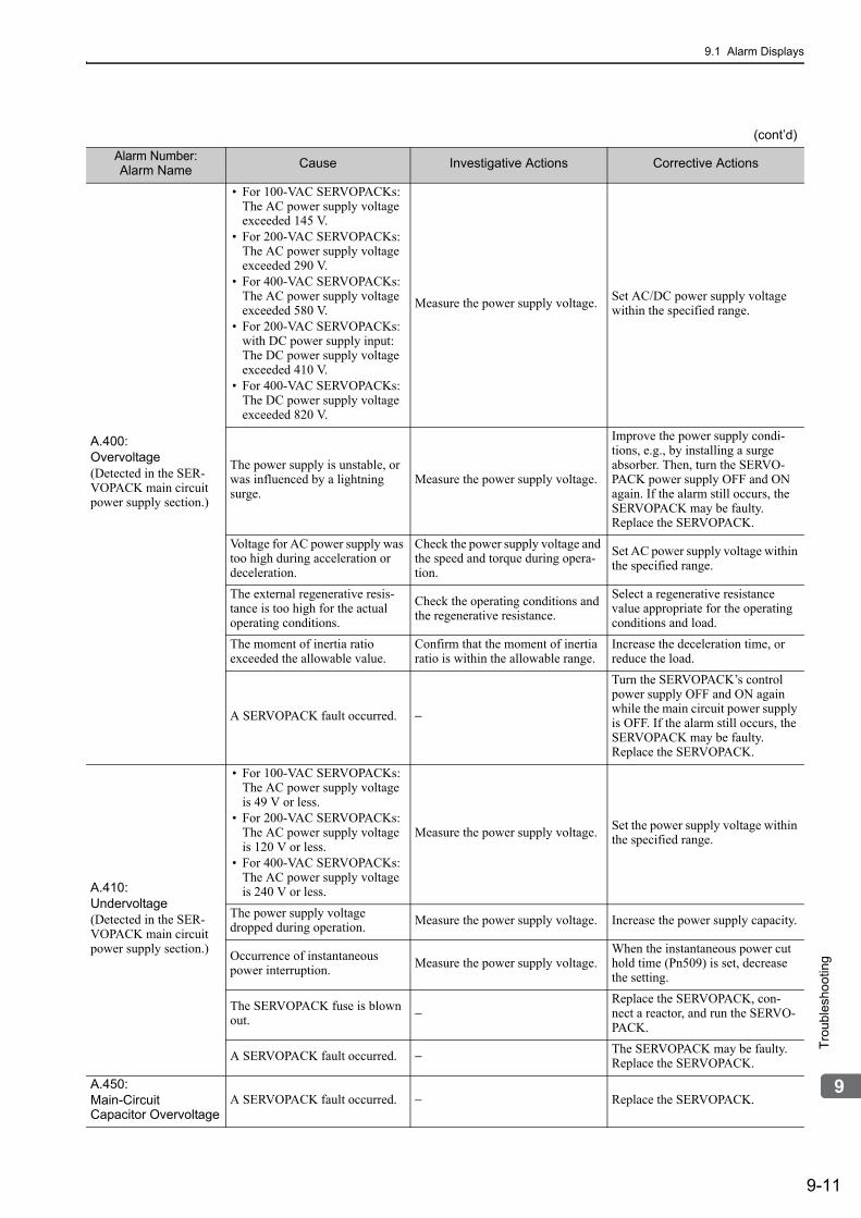
9.1 Alarm Displays
9-11
9
Tro
uble
sho
otin
g
A.400:Overvoltage(Detected in the SER-VOPACK main circuit power supply section.)
• For 100-VAC SERVOPACKs:The AC power supply voltage exceeded 145 V.
• For 200-VAC SERVOPACKs:The AC power supply voltage exceeded 290 V.
• For 400-VAC SERVOPACKs:The AC power supply voltage exceeded 580 V.
• For 200-VAC SERVOPACKs: with DC power supply input: The DC power supply voltage exceeded 410 V.
• For 400-VAC SERVOPACKs: The DC power supply voltage exceeded 820 V.
Measure the power supply voltage. Set AC/DC power supply voltage within the specified range.
The power supply is unstable, or was influenced by a lightning surge.
Measure the power supply voltage.
Improve the power supply condi-tions, e.g., by installing a surge absorber. Then, turn the SERVO-PACK power supply OFF and ON again. If the alarm still occurs, the SERVOPACK may be faulty. Replace the SERVOPACK.
Voltage for AC power supply was too high during acceleration or deceleration.
Check the power supply voltage and the speed and torque during opera-tion.
Set AC power supply voltage within the specified range.
The external regenerative resis-tance is too high for the actual operating conditions.
Check the operating conditions and the regenerative resistance.
Select a regenerative resistance value appropriate for the operating conditions and load.
The moment of inertia ratio exceeded the allowable value.
Confirm that the moment of inertia ratio is within the allowable range.
Increase the deceleration time, or reduce the load.
A SERVOPACK fault occurred. −
Turn the SERVOPACK’s control power supply OFF and ON again while the main circuit power supply is OFF. If the alarm still occurs, the SERVOPACK may be faulty. Replace the SERVOPACK.
A.410:Undervoltage(Detected in the SER-VOPACK main circuit power supply section.)
• For 100-VAC SERVOPACKs:The AC power supply voltage is 49 V or less.
• For 200-VAC SERVOPACKs: The AC power supply voltage is 120 V or less.
• For 400-VAC SERVOPACKs: The AC power supply voltage is 240 V or less.
Measure the power supply voltage. Set the power supply voltage within the specified range.
The power supply voltage dropped during operation. Measure the power supply voltage. Increase the power supply capacity.
Occurrence of instantaneous power interruption.
Measure the power supply voltage.When the instantaneous power cut hold time (Pn509) is set, decrease the setting.
The SERVOPACK fuse is blown out. −
Replace the SERVOPACK, con-nect a reactor, and run the SERVO-PACK.
A SERVOPACK fault occurred. − The SERVOPACK may be faulty. Replace the SERVOPACK.
A.450:Main-Circuit Capacitor Overvoltage
A SERVOPACK fault occurred. − Replace the SERVOPACK.
(cont’d)
Alarm Number:Alarm Name
Cause Investigative Actions Corrective Actions

9 Troubleshooting
9.1.2 Troubleshooting of Alarms
9-12
A.510:Overspeed(The servomotor speed exceeds the maximum.)
The order of phases U, V, and W in the servomotor wiring is incor-rect.
Check the motor wiring.Confirm that the servomotor is cor-rectly wired.
A reference value exceeding the overspeed detection level was input.
Check the input value. Reduce the reference value or adjust the gain.
The motor speed exceeded the maximum. Check the motor speed waveform.
Reduce the speed reference input gain, adjust the servo gain, or recon-sider the operating conditions.
A SERVOPACK fault occurred. − The SERVOPACK may be faulty. Replace the SERVOPACK.
A.511:Overspeed of Encoder Output Pulse Rate
The encoder output pulse fre-quency exceeded the limit.
Check the encoder output pulse set-ting.
Decrease the setting of the encoder output pulse (Pn212).
The encoder output pulse output frequency exceeded the limit because the motor speed was too high.
Check the encoder output pulse out-put setting and motor speed. Decrease the motor speed.
A.520:Vibration Alarm
Abnormal vibration was detected at the motor speed.
Check for abnormal noise from the servomotor, and check the speed and torque waveforms during oper-ation.
Reduce the motor speed or reduce the speed loop gain (Pn100).
The moment of inertia ratio (Pn103) value is greater than the actual value or is greatly changed.
Check the moment of inertia ratio. Set the moment of inertia ratio (Pn103) to an appropriate value.
A.521:Autotuning Alarm(Vibration was detected while executing the one-parameter tuning, EasyFFT, or tuning-less function.)
The servomotor vibrated consid-erably while performing tuning-less function.
Check the motor speed waveform.
Reduce the load so that the moment of inertia ratio falls within the allowable value, or raise the load level using the tuning-less levels setting (Fn200) or reduce the rigid-ity level.
The servomotor vibrated consid-erably during one-parameter tun-ing or EasyFFT.
Check the motor speed waveform.Check the operation procedure of corresponding function and take a corrective action.
A.710:Overload (High Load)A.720:Overload (Low Load)
Incorrect wiring or contact fault of servomotor and encoder. Check the wiring. Confirm that the servomotor and
encoder are correctly wired.
Operation beyond the overload protection characteristics.
Check the servomotor overload characteristics and executed run command.
Reconsider the load conditions and operating conditions. Or, increase the motor capacity.
Excessive load was applied during operation because the ser-vomotor was not driven due to mechanical problems.
Check the executed operation refer-ence and motor speed.
Remove the mechanical problems.
A SERVOPACK fault occurred. − The SERVOPACK may be faulty. Replace the SERVOPACK.
A.730:A.731:Dynamic Brake Overload(An excessive power consumption of dynamic brake was detected.)
The servomotor rotates because of external force.
Check the operation status.Take measures to ensure the servo-motor will not rotate because of external force.
The rotating energy at a DB stop exceeds the DB resistance capac-ity.
Check the power consumed by DB resistance (Un00B) to see how many times the DB has been used.
Reconsider the following:• Reduce the motor reference
speed.• Reduce the moment of inertia
ratio.• Reduce the number of times of
the DB stop operation.
A SERVOPACK fault occurred. − The SERVOPACK may be faulty. Replace the SERVOPACK.
(cont’d)
Alarm Number:Alarm Name
Cause Investigative Actions Corrective Actions

9.1 Alarm Displays
9-13
9
Tro
uble
sho
otin
g
A.740:Overload of Surge Current Limit Resistor(The main circuit power is turned ON/OFF too frequently.)
The inrush current limit resistor operation frequency at the main circuit power supply ON/OFF operation exceeds the allowable range.
− Reduce the frequency of turning the main circuit power supply ON/OFF.
A SERVOPACK fault occurred. − The SERVOPACK may be faulty. Replace the SERVOPACK.
A.7A0:Heat Sink Overheated(Detected when the heat sink temperature exceeds 100°C.)
The surrounding air temperature is too high.
Check the surrounding air tempera-ture using a thermostat.
Decrease the surrounding air tem-perature by improving the SERVO-PACK installation conditions.
The overload alarm has been reset by turning OFF the power too many times.
Check the alarm history display (Fn000) to see if the overload alarm was reported.
Change the method for resetting the alarm.
Excessive load or operation beyond the regenerative energy processing capacity.
Check the accumulated load ratio (Un009) to see the load during oper-ation, and the regenerative load ratio (Un00A) to see the regenera-tive energy processing capacity.
Reconsider the load and operating conditions.
Incorrect SERVOPACK installa-tion orientation or/and insuffi-cient space around the SERVOPACK.
Check the SERVOPACK installa-tion conditions.
Install the SERVOPACK correctly as specified.
A SERVOPACK fault occurred. − The SERVOPACK may be faulty. Replace the SERVOPACK.
A.7Ab:Built-in Fan in SERVOPACK Stopped
The fan inside the SERVOPACK stopped.
Check for foreign matter or debris inside the SERVOPACK.
Remove foreign matter or debris from the SERVOPACK. If the alarm still occurs, the SERVO-PACK may be faulty. Replace the SERVOPACK.
A.810:Encoder Backup Error(Only when an absolute encoder is connected.)(Detected on the encoder side.)
Alarm occurred when the power to the absolute encoder was ini-tially turned ON.
Check to see if the power was turned ON initially. Set up the encoder (Fn008).
The encoder cable disconnected, and connected again.
Check to see if the power was turned ON initially.
Confirm the connection and set up the encoder (Fn008).
The power from both the control power supply (+5 V) from the SERVOPACK and the battery power supply is not being sup-plied.
Check the encoder connector bat-tery or the connector contact status.
Replace the battery or take similar measures to supply power to the encoder, and set up the encoder (Fn008).
An absolute encoder fault occurred. −
If the alarm cannot be reset by set-ting up the encoder again, replace the servomotor.
A SERVOPACK fault occurred. − The SERVOPACK may be faulty. Replace the SERVOPACK.
A.820:Encoder Checksum Error(Detected on the encoder side.)
An encoder fault occurred. −
• Absolute encoder Set up the encoder again using Fn008. If the alarm still occurs, the servomotor may be faulty. Replace the servomotor.
• Single-turn absolute encoder or incremental encoderThe servomotor may be faulty. Replace the servomotor.
A SERVOPACK fault occurred. − The SERVOPACK may be faulty. Replace the SERVOPACK.
(cont’d)
Alarm Number:Alarm Name
Cause Investigative Actions Corrective Actions

9 Troubleshooting
9.1.2 Troubleshooting of Alarms
9-14
A.830:Absolute Encoder Battery Error(The absolute encoder battery voltage is lower than the specified value.)
The battery connection is incor-rect. Check the battery connection. Reconnect the battery.
The battery voltage is lower than the specified value 2.7 V. Measure the battery voltage. Replace the battery.
A SERVOPACK fault occurred. − The SERVOPACK may be faulty. Replace the SERVOPACK.
A.840:Encoder Data Error(Detected on the encoder side.)
An encoder malfunctioned. −
Turn the power supply to the SER-VOPACK OFF and ON again. If the alarm still occurs, the servomotor may be faulty. Replace the servo-motor.
Malfunction of encoder because of noise interference, etc. −
Correct the wiring around the encoder by separating the encoder cable from the servomotor main cir-cuit cable or by checking the grounding and other wiring.
A.850:Encoder Overspeed(Detected when the con-trol power supply was turned ON.)(Detected on the encoder side.)
The servomotor speed is higher than 200 min-1 when the control power supply was turned ON.
Check the motor rotating speed (Un000) to confirm the servomotor speed when the power is turned ON.
Reduce the servomotor speed to a value less than 200 min-1, and turn ON the control power supply.
An encoder fault occurred. −
Turn the power supply to the SER-VOPACK OFF and ON again. If the alarm still occurs, the servomotor may be faulty. Replace the servo-motor.
A SERVOPACK fault occurred. −
Turn the power supply to the SER-VOPACK OFF and ON again. If the alarm still occurs, the SERVO-PACK may be faulty. Replace the SERVOPACK.
A.860:Encoder Overheated(Only when an absolute encoder is connected.)(Detected on the encoder side.)
The ambient operating tempera-ture around the servomotor is too high.
Measure the ambient operating tem-perature around the servomotor.
Reduce the ambient operating tem-perature of the servomotor to 40°C or less.
The motor load is greater than the rated load.
Check the accumulated load ratio (Un009) to see the load.
Operate the SERVOPACK so that the motor load remains within the specified range.
An encoder fault occurred. −
Turn the power supply to the SER-VOPACK OFF and ON again. If the alarm still occurs, the servomotor may be faulty. Replace the servo-motor.
A SERVOPACK fault occurred. −
Turn the power supply to the SER-VOPACK OFF and ON again. If the alarm still occurs, the SERVO-PACK may be faulty. Replace the SERVOPACK.
A.8A0:External Encoder Error
Setting the zero point position of external absolute encoder failed because the servomotor rotated.
Before setting the zero point posi-tion, use the fully-closed feedback pulse counter (Un00E) to confirm that the servomotor is not rotating.
The servomotor must be stopped while setting the zero point posi-tion.
An external encoder fault occurred. − Replace the external encoder.
A.8A1:External Encoder Error of Module
An external encoder fault occurred. − Replace the external encoder.
A serial converter unit fault occurred. − Replace the serial converter unit.
A.8A2:External Encoder Error of Sensor(Incremental)
An external encoder fault occurred.
− Replace the external encoder.
(cont’d)
Alarm Number:Alarm Name
Cause Investigative Actions Corrective Actions

9.1 Alarm Displays
9-15
9
Tro
uble
sho
otin
g
A.8A3:External Encoder Error of Position(Absolute)
An external absolute encoder fault occurred. −
The external absolute encoder may be faulty. Refer to the encoder man-ufacturer’s instruction manual for corrective actions.
A.8A5:External Encoder Overspeed
The overspeed from the external encoder occurred.
Check the maximum speed of the external encoder.
Keep the external encoder below its maximum speed.
A.8A6:External Encoder Overheated
The overheat from the external encoder occurred. − Replace the external encoder.
A.b31:Current Detection Error 1
The current detection circuit for phase U is faulty. −
Turn the power supply to the SER-VOPACK OFF and ON again. If the alarm still occurs, the SERVO-PACK may be faulty. Replace the SERVOPACK.
A.b32:Current Detection Error 2
The current detection circuit for phase V is faulty. −
Turn the power supply to the SER-VOPACK OFF and ON again. If the alarm still occurs, the SERVO-PACK may be faulty. Replace the SERVOPACK.
A.b33:Current Detection Error 3
The detection circuit for the cur-rent is faulty. −
Turn the power supply to the SER-VOPACK OFF and ON again. If the alarm still occurs, the SERVO-PACK may be faulty. Replace the SERVOPACK.
The servomotor main circuit cable is disconnected.
Check for disconnection of the ser-vomotor main circuit cable. Correct the servomotor wiring.
A.b6A:MECHATROLINK Communications ASIC Error 1
SERVOPACK MECHA-TROLINK communication sec-tion fault.
−
Turn the power supply to the SER-VOPACK OFF and ON again. If the alarm still occurs, the SERVO-PACK may be faulty. Replace the SERVOPACK.
A.b6b:MECHATROLINK Communications ASIC Error 2
MECHATROLINK data recep-tion error occurred due to noise interference.
−
Take measures against noise. Check the MECHATROLINK communi-cations cable and FG wiring and take measures such as adding ferrite core on the MECHATROLINK communications cable.
SERVOPACK MECHA-TROLINK communication sec-tion fault.
−
Turn the power supply to the SER-VOPACK OFF and ON again. If the alarm still occurs, the SERVO-PACK may be faulty. Replace the SERVOPACK.
A.bE0:Firmware Error
A SERVOPACK fault occurred. −
Turn the power supply OFF and then ON again. If the alarm still occurs, the SERVOPACK may be faulty. Replace the SERVOPACK.
A.bF0:System Alarm 0
A SERVOPACK fault occurred. −
Turn the power supply to the SER-VOPACK OFF and ON again. If the alarm still occurs, the SERVO-PACK may be faulty. Replace the SERVOPACK.
A.bF1:System Alarm 1
A SERVOPACK fault occurred. −
Turn the power supply to the SER-VOPACK OFF and ON again. If the alarm still occurs, the SERVO-PACK may be faulty. Replace the SERVOPACK.
(cont’d)
Alarm Number:Alarm Name
Cause Investigative Actions Corrective Actions

9 Troubleshooting
9.1.2 Troubleshooting of Alarms
9-16
A.bF2:System Alarm 2
A SERVOPACK fault occurred. −
Turn the power supply to the SER-VOPACK OFF and ON again. If the alarm still occurs, the SERVO-PACK may be faulty. Replace the SERVOPACK.
A.bF3:
System Alarm 3A SERVOPACK fault occurred. −
Turn the power supply to the SER-VOPACK OFF and ON again. If the alarm still occurs, the SERVO-PACK may be faulty. Replace the SERVOPACK.
A.bF4:System Alarm 4
A SERVOPACK fault occurred. −
Turn the power supply to the SER-VOPACK OFF and ON again. If the alarm still occurs, the SERVO-PACK may be faulty. Replace the SERVOPACK.
A.C10:Servo Overrun Detected(Detected when the servomotor power is ON.)
The order of phases U, V, and W in the servomotor wiring is incor-rect.
Check the motor wiring.Confirm that the servomotor is cor-rectly wired.
An encoder fault occurred. −
If the alarm still occurs after turning the power OFF and then ON again, even though the servomotor is cor-rectly wired, the servomotor may be faulty. Replace the servomotor.
A SERVOPACK fault occurred. −
Turn the power supply to the SER-VOPACK OFF and ON again. If the alarm still occurs, the SERVO-PACK may be faulty. Replace the SERVOPACK.
A.C80:Absolute Encoder Clear Error and Multi-turn Limit Set-ting Error
An encoder fault occurred. −
Turn the power supply to the SER-VOPACK OFF and ON again. If the alarm still occurs, the servomotor may be faulty. Replace the servo-motor.
A SERVOPACK fault occurred. −
Turn the power supply to the SER-VOPACK OFF and ON again. If the alarm still occurs, the SERVO-PACK may be faulty. Replace the SERVOPACK.
A.C90:Encoder Communications Error
Contact fault of connector or incorrect wiring for encoder cable.
Check the connector contact status for encoder cable.
Re-insert the connector and confirm that the encoder is correctly wired.
Cable disconnection for encoder cable or short-circuit.Or, incorrect cable impedance.
Check the encoder cable.Use the cable with the specified rat-ing.
Corrosion caused by improper temperature, humidity, or gas, short-circuit caused by intrusion of water drops or cutting oil, or connector contact fault caused by vibration.
Check the operating environment.
Improve the operating environmen-tal conditions, and replace the cable. If the alarm still occurs, replace the SERVOPACK.
Malfunction caused by noise interference. −
Correct the wiring around the encoder by separating the encoder cable from the servomotor main cir-cuit cable or by checking the grounding and other wiring.
A SERVOPACK fault occurred. −
Connect the servomotor to another SERVOPACK, and turn ON the control power. If no alarm occurs, the SERVOPACK may be faulty. Replace the SERVOPACK.
(cont’d)
Alarm Number:Alarm Name
Cause Investigative Actions Corrective Actions

9.1 Alarm Displays
9-17
9
Tro
uble
sho
otin
g
A.C91:Encoder Communications Position Data Error
Noise interference occurred on the I/O signal line because the encoder cable is bent and the sheath is damaged.
Check the encoder cable and con-nector.
Confirm that there is no problem with the cable layout.
The encoder cable is bundled with a high-current line or near a high-current line.
Check the cable layout for encoder cable.
Confirm that there is no surge volt-age on the cable.
The FG potential varies because of influence from machines on the servomotor side, such as the welder.
Check the cable layout for encoder cable.
Properly ground the machines to separate from the encoder FG.
A.C92:Encoder Communications Timer Error
Noise interference occurred on the I/O signal line from the encoder.
− Take countermeasures against noise for the encoder wiring.
Excessive vibration and shocks were applied to the encoder.
Check the operating environment. Reduce the machine vibration or correctly install the servomotor.
An encoder fault occurred. −
Turn the power supply to the SER-VOPACK OFF and ON again. If the alarm still occurs, the servomotor may be faulty. Replace the servo-motor.
A SERVOPACK fault occurred. −
Turn the power supply to the SER-VOPACK OFF and ON again. If the alarm still occurs, the SERVO-PACK may be faulty. Replace the SERVOPACK.
A.CA0:Encoder Parameter Error
An encoder fault occurred. −
Turn the power supply to the SER-VOPACK OFF and ON again. If the alarm still occurs, the servomotor may be faulty. Replace the servo-motor.
A SERVOPACK fault occurred. −
Turn the power supply to the SER-VOPACK OFF and ON again. If the alarm still occurs, the SERVO-PACK may be faulty. Replace the SERVOPACK.
(cont’d)
Alarm Number:Alarm Name
Cause Investigative Actions Corrective Actions

9 Troubleshooting
9.1.2 Troubleshooting of Alarms
9-18
A.Cb0:Encoder Echoback Error
The wiring and contact for encoder cable are incorrect.
Check the wiring. Correct the wiring.
Noise interference occurred due to incorrect cable specifications of encoder cable.
−
Use tinned annealed copper shielded twisted-pair or screened unshielded twisted-pair cable with a core of at least 0.12 mm2.
Noise interference occurred because the wiring distance for the encoder cable is too long.
− The wiring distance must be 50 m max.
The FG potential varies because of influence from machines on the servomotor side, such as the welder.
Check the cable layout for encoder cable.
Properly ground the machines to separate from encoder FG.
Excessive vibration and shocks were applied to the encoder. Check the operating environment.
Reduce the machine vibration or correctly install the servomotor.
An encoder fault occurred. −
Turn the power supply to the SER-VOPACK OFF and ON again. If the alarm still occurs, the servomotor may be faulty. Replace the servo-motor.
A SERVOPACK fault occurred. −
Turn the power supply to the SER-VOPACK OFF and ON again. If the alarm still occurs, the SERVO-PACK may be faulty. Replace the SERVOPACK.
A.CC0:Multiturn Limit Disagreement
When using a direct drive (DD) servomotor, the multiturn limit value (Pn205) is different from that of the encoder.
Check the value of the Pn205.Correct the setting of Pn205 (0 to 65535).
The multiturn limit value of the encoder is different from that of the SERVOPACK. Or, the multi-turn limit value of the SERVO-PACK has been changed.
Check the value of the Pn205 of the SERVOPACK.
Execute Fn013 at the occurrence of alarm.
A SERVOPACK fault occurred. −
Turn the power supply to the SER-VOPACK OFF and ON again. If the alarm still occurs, the SERVO-PACK may be faulty. Replace the SERVOPACK.
A.CF1:Feedback Option Module Communications Error(Reception error)
Wiring of cable between serial converter unit and SERVOPACK is incorrect or contact is faulty.
Check the external encoder wiring. Correct the cable wiring.
The specified cable is not used between serial converter unit and SERVOPACK.
Confirm the external encoder wir-ing specifications.
Use the specified cable.
Cable between serial converter unit and SERVOPACK is too long.
Measure the length of this cable. Use 20-m cable max.
Sheath of cable between serial converter unit and SERVOPACK is broken.
Check the cable for damage. Replace the cable.
A.CF2:Feedback Option Module Communications Error(Timer stop)
Noise interferes with the cable between serial converter unit and SERVOPACK.
−
Correct the wiring around serial converter unit, e.g., separating I/O signal line from main circuit cable or grounding.
A serial converter unit fault occurred.
− Replace the serial converter unit.
A SERVOPACK fault occurred. − Replace the SERVOPACK.
(cont’d)
Alarm Number:Alarm Name
Cause Investigative Actions Corrective Actions

9.1 Alarm Displays
9-19
9
Tro
uble
sho
otin
g
A.d00:Position Error Overflow (Position error exceeded the value set in the excessive position error alarm level (Pn520).)
The servomotor U, V, and W wir-ings is faulty.
Check the servomotor main circuit cable connection.
Confirm that there is no contact fault in the motor wiring or encoder wiring.
The position reference speed is too high.
Reduce the reference speed, and operate the SERVOPACK.
Reduce the position reference speed or acceleration of position refer-ence. Or, reconsider the electronic gear ratio.
The acceleration of the position reference is too high.
Reduce the reference acceleration, and operate the SERVOPACK.
Reduce the reference acceleration of the position reference using a MECHATROLINK command, or smooth the acceleration of the posi-tion reference by selecting the posi-tion reference filter (ACCFIL) using a MECHATROLINK com-mand.
Setting of the excessive position error alarm level (Pn520) is low against the operating condition.
Check the alarm level (Pn520) to see if it is set to an appropriate value.
Set the Pn520 to proper value.
A SERVOPACK fault occurred. −
Turn the power supply to the SER-VOPACK OFF and ON again. If the alarm still occurs, the SERVO-PACK may be faulty. Replace the SERVOPACK.
A.d01:Position Error Overflow Alarm at Servo ON
This alarm occurs if the servomo-tor power is turned ON when the position error is greater than the set value of Pn526 while the ser-vomotor power is OFF.
Check the position error amount (Un008) while the servomotor power is OFF.
Correct the excessive position error alarm level at servo ON (Pn526).
A.d02:Position Error Overflow Alarm by Speed Limit at Servo ON
When the position errors remain in the error counter, Pn529 limits the speed if the servomotor power is ON. If Pn529 limits the speed in such a state, this alarm occurs when position references are input and the number of position errors exceeds the value set for the excessive position error alarm level (Pn520).
−
Correct the excessive position error alarm level (Pn520).Or, adjust the speed limit level at servo ON (Pn529).
A.d10:Motor-load Position Error Overflow
Motor rotation direction and external encoder installation direction are opposite.
Check the servomotor rotation direction and the external encoder installation direction.
Install the external encoder in the opposite direction, or change the setting of the external encoder usage method (Pn002.3) to reverse the direction.
Mounting of the load (e.g., stage) and external encoder joint instal-lation are incorrect.
Check the external encoder mechanical connection. Check the mechanical joints.
A.E02:MECHATROLINKInternal Synchronization Error 1
MECHATROLINK transmission cycle fluctuated.
− Remove the cause of transmission cycle fluctuation at host controller.
A SERVOPACK fault occurred. −
Turn the power supply to the SER-VOPACK OFF and ON again. If the alarm still occurs, the SERVO-PACK may be faulty. Replace the SERVOPACK.
A.E40:MECHATROLINK Transmission Cycle Setting Error
Setting of MECHATROLINK transmission cycle is out of speci-fications range.
Check the MECHATROLINK transmission cycle setting.
Set the transmission cycle to the proper value.
(cont’d)
Alarm Number:Alarm Name
Cause Investigative Actions Corrective Actions

9 Troubleshooting
9.1.2 Troubleshooting of Alarms
9-20
A.E50:MECHATROLINK Synchronization Error
WDT data of host controller was not updated correctly.
Check the WDT data updating for the host controller.
Update the WDT data at the host controller correctly.
A SERVOPACK fault occurred. −
Turn the power supply to the SER-VOPACK OFF and ON again. If the alarm still occurs, the SERVO-PACK may be faulty. Replace the SERVOPACK.
A.E51:MECHATROLINK Synchronization Failed
WDT data of host controller was not updated correctly at the syn-chronization communications start, and synchronization com-munications could not start.
Check the WDT data updating for the host controller.
Update the WDT data at the host controller correctly.
A SERVOPACK fault occurred. −
Turn the power supply to the SER-VOPACK OFF and ON again. If the alarm still occurs, the SERVO-PACK may be faulty. Replace the SERVOPACK.
A.E60:MECHATROLINK Communications error(Reception error)
MECHATROLINK wiring is incorrect.
Check the MECHATROLINK wir-ings.
Correct the MECHATROLINK wir-ing.Connect the terminator correctly.
MECHATROLINK data recep-tion error occurred due to noise interference.
−
Take measures against noise. Check the MECHATROLINK communi-cations cable and FG wiring and take measures such as adding ferrite core on the MECHATROLINK communications cable.
A SERVOPACK fault occurred. −
Turn the power supply to the SER-VOPACK OFF and ON again. If the alarm still occurs, the SERVO-PACK may be faulty. Replace the SERVOPACK.
A.E61:MECHATROLINK Transmission Cycle Error(Synchronization interval error)
MECHATROLINK transmission cycle fluctuated.
Check the MECHATROLINK transmission cycle setting.
Remove the cause of transmission cycle fluctuation at host controller.
A SERVOPACK fault occurred. −
Turn the power supply to the SER-VOPACK OFF and ON again. If the alarm still occurs, the SERVO-PACK may be faulty. Replace the SERVOPACK.
A.E71:Safety Option Module Detection Failure
The connection between the SERVOPACK and the safety option module is faulty.
Check the connection between the SERVOPACK and the safety option module.
Correctly connect the safety option module.
The safety option module was disconnected.
–
Execute Fn014 (Resetting configu-ration error in option module) from the digital operator or SigmaWin+, and then turn the power supply OFF and ON again.
A safety option module fault occurred.
– Replace the safety option module.
A SERVOPACK fault occurred. – Replace the SERVOPACK.
A.E72:Feedback OptionModule DetectionFailure
The connection between the SERVOPACK and the Feedback Option Module is Faulty.
Check the connection between the SERVOPACK and the Feedback Option Module.
Correctly connect the Feedback Option Module.
The Feedback Option Module was disconnected. −
Execute Fn014 (Resetting configu-ration error in option module), and then turn the power supply OFF and ON again.
A Feedback Option Module fault occurred. − Replace the Feedback Option Mod-
ule.
A SERVOPACK fault occurred. − Replace the SERVOPACK.
(cont’d)
Alarm Number:Alarm Name
Cause Investigative Actions Corrective Actions

9.1 Alarm Displays
9-21
9
Tro
uble
sho
otin
g
A.E74:Unsupported Safety Option Module
A safety option module fault occurred.
− Replace the safety option module.
A unsupported safety option module was connected.
Refer to the catalog of the con-nected safety option module.
Connect a compatible safety option module.
A.E75:Unsupported Feedback Option Module
A feedback option module fault occurred. − Replace the feedback option mod-
ule.
A unsupported feedback option module was connected.
Refer to the catalog of the con-nected feedback option module or the manual of the SERVOPACK.
Connect a compatible feedback option module.
A.EA2:DRV Alarm 2(SERVOPACK WDT error)
MECHATROLINK transmission cycle fluctuated.
Check the MECHATROLINK transmission cycle setting.
Remove the cause of transmission cycle fluctuation at host controller.
A SERVOPACK fault occurred. −
Turn the power supply to the SER-VOPACK OFF and ON again. If the alarm still occurs, the SERVO-PACK may be faulty. Replace the SERVOPACK.
A.Eb1:Safety Function Signal Input Timing Error
The lag between activations of the input signals /HWBB1 and /HWBB2 for the HWBB function is ten second or more.
Measure the time lag between the /HWBB1 and /HWBB2 signals.
The output signal circuits or devices for /HWBB1 and /HWBB2 or the SERVOPACK input signal circuits may be faulty. Alternatively, the input signal cables may be disconnected. Check if any of these items are faulty or have been disconnected.
A.Ed1:Command Execution Timeout
A timeout error occurred when using an MECHATROLINK command.
Check the motor status when the command is executed.
Execute the SV_ON or SENS_ON command only when the motor is not running.
For fully-closed loop control, check the status of the external encoder after an output is made to execute the command.
Execute the SENS_ON command only when an external encoder is connected.
A.F10:Main Circuit Cable Open Phase(A low voltage contin-ued for one second or longer in either phase R, S, or T when the main circuit power supply was ON.)(Detected when the main circuit power supply is turned ON.)
The three-phase power supply wiring is incorrect. Check the power supply wiring. Confirm that the power supply is
correctly wired.
The three-phase power supply is unbalanced.
Measure the voltage at each phase of the three-phase power supply.
Balance the power supply by chang-ing phases.
A single-phase power is input without setting Pn00B.2 (power supply method for three-phase SERVOPACK) to 1 (single-phase power supply).
Check the power supply and the parameter setting.
Match the parameter setting to the power supply.
A SERVOPACK fault occurred. −
Turn the power supply to the SER-VOPACK OFF and ON again. If the alarm still occurs, the SERVO-PACK may be faulty. Replace the SERVOPACK.
A.F50:Servomotor Main Circuit Cable Disconnection(The servomotor did not operate or power was not supplied to the servomotor even though the SV_ON (Servo ON) command was input when the servomotor was ready to receive it.)
A SERVOPACK fault occurred. − The SERVOPACK may be faulty. Replace the SERVOPACK.
The wiring is not correct or there is a faulty contact in the motor wiring.
Check the wiring. Make sure that the servomotor is correctly wired.
(cont’d)
Alarm Number:Alarm Name
Cause Investigative Actions Corrective Actions

9 Troubleshooting
9.1.2 Troubleshooting of Alarms
9-22
FL-1*3:System Alarm
SERVOPACK failure −
Turn the power supply to the SER-VOPACK OFF and ON again. If the alarm still occurs, the SERVO-PACK may be faulty. Replace the SERVOPACK.
FL-2*3:System Alarm
CPF00:Digital Operator Transmission Error 1
The contact between the digital operator and the SERVOPACK is faulty.
Check the connector contact. Insert securely the connector or replace the cable.
Malfunction caused by noise interference.
− Keep the digital operator or the cable away from noise sources.
CPF01:Digital OperatorTransmission Error 2
A digital operator fault occurred. −
Disconnect the digital operator and then re-connect it. If the alarm still occurs, the digital operator may be faulty. Replace the digital operator.
A SERVOPACK fault occurred. −
Turn the power supply to the SER-VOPACK OFF and ON again. If the alarm still occurs, the SERVO-PACK may be faulty. Replace the SERVOPACK.
∗3. These alarms are not stored in the alarm history and are displayed only in the panel display.
(cont’d)
Alarm Number:Alarm Name
Cause Investigative Actions Corrective Actions

9.2 Warning Displays
9-23
9
Tro
uble
sho
otin
g
9.2 Warning DisplaysThe following sections describe troubleshooting in response to warning displays.
The warning name and warning meaning output are listed in order of the warning numbers in 9.2.1 List of Warnings.
The causes of warnings and troubleshooting methods are provided in 9.2.2 Troubleshooting of Warnings.
9.2.1 List of WarningsThis section provides list of warnings.
∗1. Use Pn008.2 to activate or not the warning detection.∗2. Use Pn800.1 to activate or not the warning detection.∗3. Use Pn008.1 to activate or not the warning detection.
Warning Number
Warning Name Meaning
A.900*1 Position Error Overflow Position error exceeded the parameter setting (Pn520×Pn51E/100).
A.901*1 Position Error Overflow Alarm at Servo ON
When the servomotor power is ON, the position error exceeded the parame-ter setting (Pn526×Pn528/100).
A.910 OverloadThis warning occurs before the overload alarms (A.710 or A.720) occur. If the warning is ignored and operation continues, an overload alarm may occur.
A.911 VibrationAbnormal vibration at the motor speed was detected. The detection level is the same as A.520. Set whether to output an alarm or warning by the vibra-tion detection switch (Pn310).
A.920*1 Regenerative OverloadThis warning occurs before the regenerative overload alarm (A.320) occurs. If the warning is ignored and operation continues, a regenerative overload alarm may occur.
A.921*1 Dynamic Brake OverloadThis warning occurs before dynamic brake overload alarm (A.731) occurs. If the warning is ignored and operation continues, a dynamic brake overload alarm may occur.
A.930*1 Absolute Encoder Battery Error
This warning occurs when the voltage of absolute encoder’s battery is lowered.
A.94A*2 Data Setting Warning 1(Parameter Number Error) Incorrect command parameter number was set.
A.94B*2 Data Setting Warning 2(Out of Range) Command input data is out of range.
A.94C*2 Data Setting Warning 3(Calculation Error) Calculation error was detected.
A.94D*2 Data Setting Warning 4(Parameter Size) Data size does not match.
A.94E*2 Data Setting Warning 5(Latch Mode Error)
Latch mode error is detected.
A.95A*2 Command Warning 1(Unsatisfying Command)
Command was sent although the conditions for sending a command were not satisfied.
A.95B*2Command Warning 2(Non-supported Command)
Unsupported command was sent.
A.95D*2 Command Warning 4(Command Interference) Command, especially latch command, interferes.
A.95E*2 Command Warning 5(Subcommand Disable) Subcommand and main command interfere.
A.95F*2 Command Warning 6(Undefined Command)
Undefined command was sent.
A.960*2 MECHATROLINKCommunications Warning
Communications error occurred during MECHATROLINK communications.
A.971*3 Undervoltage This warning occurs before undervoltage alarm (A.410) occurs. If the warn-ing is ignored and operation continues, an undervoltage alarm may occur.
A.9A0*1 Overtravel Overtravel is detected while the servomotor power is ON.

9 Troubleshooting
9.2.2 Troubleshooting of Warnings
9-24
9.2.2 Troubleshooting of WarningsRefer to the following table to identity the cause of a warning and the action to be taken. Contact your Yaskawa representative if the problem cannot be solved by the described corrective action.
Warning Num-ber: Warning
NameCause Investigative Actions Corrective Actions
A.900: Position Error Overflow
The servomotor U, V, and W wirings is faulty.
Check the servomotor main circuit cable connection.
Confirm that there is no contact fault in the motor wiring or encoder wir-ing.
The SERVOPACK gain is too low. Check the SERVOPACK gain.
Increase the servo gain by using the function such as advanced autotun-ing.
The acceleration of the position reference is too high.
Reduce the reference acceleration, and operate the SERVOPACK.
Reduce the reference acceleration of the position reference using a MECHATROLINK command, or smooth the acceleration of the posi-tion reference by selecting the posi-tion reference filter (ACCFIL) using a MECHATROLINK command.
Setting of the exces-sive position error alarm level (Pn520) is low against the operat-ing condition.
Check the alarm level (Pn520) to see if it is set to an appropriate value. Set the Pn520 to proper value.
A SERVOPACK fault occurred. −
Turn the power supply to the SER-VOPACK OFF and ON again. If the alarm still occurs, the SERVOPACK may be faulty. Replace the SERVO-PACK.
A.901: Position Error Overflow Alarm at Servo ON
When the servomotor power is ON, the posi-tion error exceeded the parameter setting (Pn526×Pn528/100).
−Set an appropriate value for the excessive position error warning level at servo ON (Pn528).
A.910: Overload(Warning before the overload alarm (A.710 or A.720).)
Incorrect wiring or contact fault of servo-motor and encoder.
Check the wiring. Confirm that the servomotor and encoder are correctly wired.
Operation beyond the overload protection characteristics.
Check the motor overload character-istics and executed run command.
Reconsider the load conditions and operating conditions. Or, increase the motor capacity.
Excessive load was applied during opera-tion because the servo-motor was not driven due to mechanical problems.
Check the executed operation refer-ence and motor speed. Remove the mechanical problems.
A SERVOPACK fault occurred. − The SERVOPACK may be faulty.
Replace the SERVOPACK.
A.911: Vibration
Abnormal vibration was detected at the motor speed.
Check for abnormal noise from the servomotor, and check the speed and torque waveforms during operation.
Reduce the motor speed or reduce the servo gain by using the function such as one-parameter tuning.
The moment of inertia ratio (Pn103) value is greater than the actual value or is greatly changed.
Check the moment of inertia ratio.Set the moment of inertia ratio (Pn103) to an appropriate value.

9.2 Warning Displays
9-25
9
Tro
uble
sho
otin
g
A.920: Regenerative Overload(Warning before the alarm A.320 occurs)
The power supply voltage exceeds the specified limit.
Measure the power supply voltage. Set the power supply voltage within the specified range.
Insufficient external regenerative resis-tance, regenerative resistor capacity, or SERVOPACK capac-ity. Or, regenerative power has been continuously flowing back.
Check the operating condition or the capacity using the capacity selec-tion Software SigmaJunmaSize+, etc.
Change the regenerative resistance, regenerative resistor capacity, or SERVOPACK capacity. Reconsider the operating conditions using the capacity selection software Sigma-JunmaSize+, etc.
Regenerative power continuously flowed back because negative load was continuously applied.
Check the load to the servomotor during operation.
Reconsider the system including servo drives, machine, and operating conditions.
A.921: Dynamic Brake Overload(Warning before the alarm A.731 occurs)
The servomotor rotates because of external force.
Check the operation status.Take measures to ensure the servo-motor will not rotate because of external force.
The rotating energy at a DB stop exceeds the DB resistance capac-ity.
Check the power consumed by DB resistance (Un00B) to see how many times the DB has been used.
Reconsider the following:• Reduce the motor reference speed.• Reduce the moment of inertia
ratio.• Reduce the number of times of the
DB stop operation.
A SERVOPACK fault occurred.
− The SERVOPACK may be faulty. Replace the SERVOPACK.
A.930: Absolute Encoder Battery Error(The absolute encoder battery voltage is lower than the specified value.)(Only when an absolute encoder is connected.)
The battery connec-tion is incorrect. Check the battery connection. Reconnect the battery.
The battery voltage is lower than the speci-fied value 2.7 V.
Measure the battery voltage. Replace the battery.
A SERVOPACK fault occurred. − The SERVOPACK may be faulty.
Replace the SERVOPACK.
A.94A Data Setting Warning 1(Parameter Num-ber Error)
Disabled parameter number was used.
Refer to 9.3 Monitoring Communi-cation Data on Occurrence of an Alarm or Warning to determine which command was the cause of the warning.
Use the correct parameter number.
A.94BData Setting Warning 2(Out of Range)
Attempted to send val-ues outside the range to the command data.
Refer to 9.3 Monitoring Communi-cation Data on Occurrence of an Alarm or Warning to determine which command was the cause of the warning.
Set the value of the parameter within the allowable range.
A.94CData Setting Warning 3(Calculation Er-ror)
Calculation result of set value is incorrect.
Refer to 9.3 Monitoring Communi-cation Data on Occurrence of an Alarm or Warning to determine which command was the cause of the warning.
Set the value of the parameter within the allowable range.
(cont’d)
Warning Num-ber: Warning
NameCause Investigative Actions Corrective Actions

9 Troubleshooting
9.2.2 Troubleshooting of Warnings
9-26
A.94DData Setting Warning 4(Parameter Size)
Parameter size set in command is incorrect.
Refer to 9.3 Monitoring Communi-cation Data on Occurrence of an Alarm or Warning to determine which command was the cause of the warning.
Use the correct parameter size.
A.94EData Setting Warning 5 (Latch mode error)
Latch mode error is detected.
Refer to 9.3 Monitoring Communi-cation Data on Occurrence of an Alarm or Warning to determine which command was the cause of the warning.
Change the setting value of Pn850 or the LT_MOD data for the LTMOD-_ON command sent by the host con-troller to the proper value.
A.95ACommand Warning 1(Unsatisfying Command)
Command sending condition is not satis-fied.
Refer to 9.3 Monitoring Communi-cation Data on Occurrence of an Alarm or Warning to determine which command was the cause of the warning.
Send a command after command sending condition is satisfied.
A.95BCommand Warning 2(Non-supported Command)
SERVOPACK received unsupported command.
Refer to 9.3 Monitoring Communi-cation Data on Occurrence of an Alarm or Warning to determine which command was the cause of the warning.
Do not sent an unsupported com-mand.
A.95DCommand Warning 4(Command Inter-ference)
Command sending condition for latch-related commands is not satisfied.
Refer to 9.3 Monitoring Communi-cation Data on Occurrence of an Alarm or Warning to determine which command was the cause of the warning.
Send a command after command sending condition is satisfied.
A.95ECommand Warning 5(Subcommand Disable)
Subcommand sending condition is not satis-fied.
Refer to 9.3 Monitoring Communi-cation Data on Occurrence of an Alarm or Warning to determine which command was the cause of the warning.
Send a command after command sending condition is satisfied.
A.95FCommand Warning 6(Undefined Com-mand)
Undefined command was sent.
Refer to 9.3 Monitoring Communi-cation Data on Occurrence of an Alarm or Warning to determine which command was the cause of the warning.
Do not use an undefined command.
A.960MECHATROLINKCommunicationsWarning
MECHATROLINK wiring is incorrect.
Confirm the wiring.
Correct the MECHATROLINK wir-ing.Or, connect a terminal to the termi-nal station.
MECHATROLINK data reception error occurred due to noise interference.
Confirm the installation conditions.
Take measures against noise. Check the MECHATROLINK communica-tions cable and FG wiring and take measures such as adding ferrite core on the MECHATROLINK commu-nications cable.
A SERVOPACK fault occurred. –
A fault occurred in the SERVO-PACK. Replace the SERVOPACK.
(cont’d)
Warning Num-ber: Warning
NameCause Investigative Actions Corrective Actions

9.2 Warning Displays
9-27
9
Tro
uble
sho
otin
g
A.971:Undervoltage
• For 100 VAC SERVOPACKs:The AC power sup-ply voltage is 60 V or less.
• For 200-VAC SERVOPACKs:The AC power sup-ply voltage is 140 V or less.
• For 400-VAC SERVOPACKs:The AC power sup-ply voltage is 280 V or less.
Measure the power supply voltage.Set the power supply voltage within the specified range.
The power supply voltage dropped during operation.
Measure the power supply voltage. Increase the power supply capacity.
Occurrence of instan-taneous power inter-ruption.
Measure the power supply voltage.When the instantaneous power cut hold time (Pn509) is set, decrease the setting.
The SERVOPACK fuse is blown out. − Replace the SERVOPACK and con-
nect a reactor to the SERVOPACK.
A SERVOPACK fault occurred. − The SERVOPACK may be faulty.
Replace the SERVOPACK.
A.9A0:Overtravel(Overtravel status is detected.)
When the servomotor power is ON, over-travel status is detected.
Check the input signal monitor (Un005) to check the status of the overtravel signals.
Refer to 9.4 Troubleshooting Mal-function Based on Operation and Conditions of the Servomotor. Even if overtravel signals were not shown by the input signal monitor (Un005), momentary overtravel may have been detected. Take the following precautions. • Do not specify movements that
would cause overtravel from the host controller.
• Check the wiring of the overtravel signals.
• Take countermeasures for noise.
(cont’d)
Warning Num-ber: Warning
NameCause Investigative Actions Corrective Actions

9 Troubleshooting
9-28
9.3 Monitoring Communication Data on Occurrence of an Alarm or WarningThe command data received on occurrence of an alarm or warning, such as a data setting warning (A.94) or a command warning (A.95) can be monitored using the following parameters. The following is an example of the data when an alarm/warning has occurred in the normal state.
Command Data Monitor at Alarm/Warning Occurrence: Pn890 to Pn89EResponse Data Monitor at Alarm/Warning Occurrence: Pn8A0 to Pn8AE
Note 1. Data is stored in little endian byte order and displayed in the hexadecimal format.2. For details on commands, refer to the Σ-V Series/DC Power Input Σ-V Series/Σ-V Series for Large-Capacity
Models User’s Manual MECHATROLINK-II Commands (Manual No.: SIEP S800000 54).
Command Byte Order
Command Data Storage at Alarm/Warning Occurrence
CMD RSP
1 Pn890.1 to 0 Pn8A0.1 to 0
2 Pn890.3 to 2 Pn8A0.3 to 2
3 Pn890.5 to 4 Pn8A0.5 to 4
4 Pn890.7 to 6 Pn8A0.7 to 6
5 to 8 Pn892 Pn8A2
9 to 12 Pn894 Pn8A4
13 to 16 Pn896 Pn8A6
17 to 20 Pn898 Pn8A8
21 to 24 Pn89A Pn8AA
25 to 28 Pn89C Pn8AC
29 to 32 Pn89E Pn8AE
Example: Pn8A0 = 87 65 43 21

9.4 Troubleshooting Malfunction Based on Operation and Conditions of the Servomotor
9-29
9
Tro
uble
sho
otin
g
9.4 Troubleshooting Malfunction Based on Operation and Conditions of the ServomotorTroubleshooting for the malfunctions based on the operation and conditions of the servomotor is provided in this section.
Be sure to turn OFF the servo system before troubleshooting items shown in bold lines in the table.
Problem Probable Cause Investigative Actions Corrective Actions
Servomotor Does Not Start
The control power supply is not ON.
Check voltage between control power terminals. Correct the wiring.
The main circuit power supply is not ON.
Check the voltage between main circuit power terminals.
Correct the wiring so that the main circuit power supply turns ON.
Wiring of I/O signal connector CN1 is faulty or disconnected.
Check if the connector CN1 is prop-erly inserted and connected.
Correct the connector CN1 connec-tion.
Wiring for servomotor main circuit cable or encoder cable is discon-nected.
Check the wiring. Correct the wiring.
Overloaded Run under no load and check the load status.
Reduce load or replace with larger capacity servomotor.
Encoder type differs from parame-ter setting (Pn002.2).
Check the settings for parameter Pn002.2.
Set parameter Pn002.2 to the encoder type being used.
Settings for the input signal selec-tions (Pn50A, Pn50B and Pn511) is incorrect.
Check the settings for parameters Pn50A, Pn50B and Pn511.
Correct the settings for parameter Pn50A, Pn50B and Pn511.
SV_ON command is not sent. Check the command sent from the host controller.
Send the SV_ON command.
SENS_ON command is not sent. Check the command sent from the host controller.
Send the command in the correct SERVOPACK sequence.
The forward run prohibited (P-OT) and reverse run prohibited (N-OT) input signals are turned OFF.
Check P-OT or N-OT input signal. Turn P-OT or N-OT input signal ON.
The safety input signal (/HWBB1 or /HWBB2) remains OFF.
Check the /HWBB1 and /HWBB2 input signal.
Set the /HWBB1 and /HWBB2 input signal to ON.When not using the safety function, mount the safety function’s jumper connector (provided as an acces-sory) on the CN8.
A SERVOPACK fault occurred. − Replace the SERVOPACK.
Servomotor Moves Instanta-neously, and then Stops
Servomotor wiring is incorrect. Check the wiring. Correct the wiring.
Encoder wiring is incorrect. Check the wiring. Correct the wiring.
Servomotor Speed Unstable
Wiring connection to servomotor is defective.
Check connections of power line (phases U, V, and W) and encoder connectors.
Tighten any loose terminals or con-nectors and correct the wiring.
Servomotor Ro-tates Without Ref-erence Input
A SERVOPACK fault occurred. − Replace the SERVOPACK.
Dynamic Brake Does Not Operate
Improper Pn001.0 settingCheck the setting for parameter Pn001.0.
Correct the setting for parameter Pn001.0.
DB resistor disconnectedCheck if excessive moment of iner-tia, motor overspeed, or DB fre-quently activated occurred.
Replace the SERVOPACK, and reduce the load.
DB drive circuit fault −There is a defective component in the DB circuit. Replace the SER-VOPACK.

9 Troubleshooting
9-30
Abnormal Noise from Servomotor
The servomotor largely vibrated during execution of tuning-less function.
Check the motor speed waveform.
Reduce the load so that the moment of inertia ratio becomes within the allowable value, or increase the load level or lower the tuning level for the tuning-less levels setting (Fn200).
Mounting is not secured.
Check if there are any loose mount-ing screws. Tighten the mounting screws.
Check if there is misalignment of couplings.
Align the couplings.
Check if there are unbalanced cou-plings. Balance the couplings.
Bearings are defective.Check for noise and vibration around the bearings. Replace the servomotor.
Vibration source at the driven machine.
Check for any foreign matter, dam-age, or deformations on the machin-ery's movable parts.
Contact the machine manufacturer.
Noise interference due to incorrect I/O signal cable specifications.
The I/O signal cable must be tinned annealed copper shielded twisted-pair or screened unshielded twisted-pair cable with a core of 0.12 mm2 min.
Use the specified I/O signal cable.
Noise interference due to length of I/O signal cable.
Check the length of the I/O signal cable.
Make the I/O signal cable length less than 3 m.
Noise interference due to incorrect cable specifications of encoder cable.
The encoder cable must be tinned annealed copper shielded twisted-pair or screened unshielded twisted-pair cable with a core of 0.12 mm2 min.
Use the specified encoder cable.
Noise interference due to length of encoder cable.
Check the length of the encoder cable.
The encoder cable must be no more than 50 m.
Noise interference due to damaged encoder cable.
Check if the encoder cable is bent and the sheath is damaged.
Replace the encoder cable and cor-rect the cable layout.
Excessive noise to the encoder cable.
Check if the encoder cable is bun-dled with a high-current line or near a high-current line.
Correct the cable layout so that no surge is applied.
The FG potential varies because of influence from machines on the ser-vomotor side, such as the welder.
Check if the machines are correctly grounded.
Properly ground the machines to separate from the encoder FG.
SERVOPACK pulse counting error due to noise interference
Check if there is noise interference on the I/O signal line from the encoder.
Take measures against noise in the encoder wiring.
Excessive vibration and shock to the encoder
Check if vibration from the machine occurred or servomotor installation is incorrect (mounting surface accu-racy, fixing, alignment, etc.).
Reduce vibration from the machine, or secure the servomotor installa-tion.
An encoder fault occurred. − Replace the servomotor.
(cont’d)
Problem Probable Cause Investigative Actions Corrective Actions

9.4 Troubleshooting Malfunction Based on Operation and Conditions of the Servomotor
9-31
9
Tro
uble
sho
otin
g
Servomotor Vi-brates at Fre-quency of Approx. 200 to 400 Hz.
Unbalanced servo gains Check to see if the servo gains have been correctly adjusted.
Execute the advanced autotuning.
Speed loop gain value (Pn100) too high.
Check the speed loop gain (Pn100).Factory setting: Kv = 40.0 Hz
Reduce the speed loop gain (Pn100).
Position loop gain value (Pn102) too high.
Check the position loop gain (Pn102).Factory setting: Kp = 40.0/s
Reduce the position loop gain (Pn102).
Incorrect speed loop integral time constant (Pn101)
Check the speed loop integral time constant (Pn101).Factory setting: Ti = 20.0 ms
Correct the speed loop integral time constant (Pn101).
Incorrect moment of inertia ratio (Pn103)
Check the moment of inertia ratio (Pn103).
Correct the moment of inertia ratio (Pn103).
High Motor Speed Overshoot on Starting and Stop-ping
Unbalanced servo gains Check to see if the servo gains have been correctly adjusted. Execute the advanced autotuning.
Speed loop gain value (Pn100) too high
Check the speed loop gain (Pn100). Factory setting: Kv = 40.0 Hz
Reduce the speed loop gain (Pn100).
Position loop gain value (Pn102) too high
Check the position loop gain (Pn102). Factory setting: Kp = 40.0/s
Reduce the position loop gain (Pn102).
Incorrect speed loop integral time constant (Pn101)
Check the speed loop integral time constant (Pn101). Factory setting: Ti = 20.0 ms
Correct the speed loop integral time constant (Pn101).
Incorrect moment of inertia ratio data (Pn103)
Check the moment of inertia ratio (Pn103).
Correct the moment of inertia ratio (Pn103).
The torque reference is saturated. Check the torque reference wave-form. Use the mode switch function.
(cont’d)
Problem Probable Cause Investigative Actions Corrective Actions

9 Troubleshooting
9-32
Absolute Encod-er Position Differ-ence Error (The position saved in the host controller when the power was turned OFF is different from the position when the power was next turned ON.)
Noise interference due to incorrect cable specifications of encoder cable.
The encoder cable must be tinned annealed copper shielded twisted-pair or screened unshielded twisted-pair cable with a core of 0.12 mm2 min.
Use the specified encoder cable.
Noise interference due to length of encoder cable.
Check the length of the encoder cable.
The encoder cable must be no more than 50 m.
Noise interference due to damaged encoder cable.
Check if the encoder cable is bent and the sheath is damaged.
Replace the encoder cable and cor-rect the cable layout.
Excessive noise to the encoder cable.
Check if the encoder cable is bun-dled with a high-current line or near a high-current line.
Correct the cable layout so that no surge is applied.
FG potential varies because of influence of machines such as weld-ers at the servomotor.
Check if the machines are correctly grounded.
Ground machines correctly, and prevent diversion to the FG on the encoder side.
SERVOPACK pulse counting error due to noise interference
Check if there is noise interference on the I/O signal line from the encoder.
Take measures against noise in the encoder wiring.
Excessive vibration and shock to the encoder
Check to see if the machine is vibrating.Also, check the installation condi-tions of the servomotor (flange face accuracy, anchoring condition, and centering).
Reduce vibration from the machine, or secure the servomotor installa-tion.
An encoder fault occurred. − Replace the servomotor.
A SERVOPACK fault occurred. − Replace the SERVOPACK.
Host controller rotational serial data reading error
Check the error detection section of the host controller.
Correct the error detection section of the host controller.
Check if the host controller is exe-cuting data parity checks.
Perform a parity check on the rota-tional serial data.
Check noise in the cable between the SERVOPACK and the host con-troller.
Implement measures against noise and perform a parity check on the rotational serial data again.
(cont’d)
Problem Probable Cause Investigative Actions Corrective Actions

9.4 Troubleshooting Malfunction Based on Operation and Conditions of the Servomotor
9-33
9
Tro
uble
sho
otin
g
Overtravel (OT)
Forward or reverse run prohibited signal is input.
Check the external power supply (+24 V) voltage for the input signal.
Correct the external power supply (+24 V) voltage.
Check if the overtravel limit switch operates properly. Correct the overtravel limit switch.
Check if the overtravel limit switch is wired correctly.
Correct the overtravel limit switch wiring.
Check the settings for parameters Pn50A and Pn50B.
Correct the settings for parameters Pn50A and Pn50B.
Forward or reverse run prohibited signal malfunctioning.
Check the fluctuation of the exter-nal power supply (+24 V) voltage for the input signal.
Stabilize the external power supply (+24 V) voltage.
Check if the overtravel limit switch operates correctly. Correct the overtravel limit switch.
Check if the overtravel limit switch wiring is correct. (check for dam-aged cables or loose screws.)
Correct the overtravel limit switch wiring.
Incorrect forward or reverse run prohibited signal (P-OT/N-OT) allocation (parameters Pn50A.3, Pn50B.0)
Check if the P-OT signal is allo-cated in Pn50A.3.
If another signal is allocated in Pn50A.3, allocate P-OT.
Check if the N-OT signal is allo-cated in Pn50B.0.
If another signal is allocated in Pn50B.0, allocate N-OT.
Incorrect servomotor stop method selection
Check the settings for parameters Pn001.0 and Pn001.1 when the ser-vomotor power is OFF.
Select a servomotor stop method other than "coast to stop."
Check the settings for parameters Pn001.0 and Pn001.1 when in torque control.
Select a servomotor stop method other than "coast to stop."
Improper Stop Po-sition by Overtrav-el (OT) Signal
Improper limit switch position and dog length − Install the limit switch at the
appropriate position.
The overtravel limit switch position is too short for the coasting distance.
− Install the overtravel limit switch at the appropriate position.
(cont’d)
Problem Probable Cause Investigative Actions Corrective Actions

9 Troubleshooting
9-34
Position Error (Without Alarm)
Noise interference due to incorrect encoder cable specifications
The encoder cable must be tinned annealed copper shielded twisted-pair or screened unshielded twisted-pair cable with a core of 0.12 mm2 min.
Use the specified encoder cable.
Noise interference due to length of encoder cable.
Check the length of the encoder cable.
The encoder cable must be no more than 50 m.
Noise influence due to damaged encoder cable.
Check if the encoder cable is bent and the sheath is damaged.
Replace the encoder cable and mod-ify the cable layout.
Excessive noise to encoder cable.Check if the encoder cable is bun-dled with a high-current line or near a high-current line.
Change the cable layout so that no surge is applied.
The FG potential varies because of influence from machines on the ser-vomotor side such as the welder.
Check if the machines are correctly grounded.
Properly ground the machines encoder FG.
SERVOPACK pulse count error due to noise
Check if the I/O signal line from the encoder is influenced by noise.
Take measures against noise in the encoder wiring.
Excessive vibration and shock to the encoder
Check if vibration from the machine occurred or servomotor installation is incorrect (mounting surface accu-racy, fixing, alignment, etc.).
Reduce the machine vibration or mount the servomotor securely.
Unsecured coupling between machine and servomotor
Check if a position error occurs at the coupling between machine and servomotor.
Secure the coupling between the machine and servomotor.
Noise interference due to improper I/O signal cable specifications
The I/O signal cable must be tinned annealed copper shielded twisted-pair or screened unshielded twisted-pair cable with a core of 0.12 mm2 min.
Use input signal cable with the specified specifications.
Noise interference due to length of I/O signal cable
Check the I/O signal cable length. Make the I/O signal cable length less than 3 m.
An encoder fault occurred. (The pulse count does not change.) − Replace the servomotor.
A SERVOPACK fault occurred. − Replace the SERVOPACK.
Servomotor Over-heated
Ambient operating temperature too high
Measure the servomotor ambient operating temperature.
Reduce the ambient operating tem-perature to 40°C or less.
Servomotor surface dirty Visually check the surface. Clean dust and oil from the surface.
Servomotor overloaded Check the load status with monitor.If overloaded, reduce load or replace with larger capacity SER-VOPACK and servomotor.
(cont’d)
Problem Probable Cause Investigative Actions Corrective Actions

10-1
10
App
endi
x
10Appendix
10.1 List of Parameters . . . . . . . . . . . . . . . . . . . . . . . . . . . . . . . . . . . . . . . . . 10-2
10.2 Parameter Recording Table . . . . . . . . . . . . . . . . . . . . . . . . . . . . . . . .10-33

10 Appendix
10-2
10.1 List of ParametersThis section contains a tables of parameters.
Note: Do not change the following parameters from the factory settings.• Reserved parameters• Parameters not described in this manual
ParameterNo. Size Name Setting
Range Units Factory Setting
When Enabled Classification Reference
Section
Pn000
2 Basic Function Select Switch 0 0000 to 00B3 − 0000 After restart Setup −
Pn001
2 Application Function Select Switch 1
0000 to 1122 − 0000 After restart Setup −
Direction Selection Reference Section
0 Sets CCW as forward direction.
4.3.11 Sets CW as forward direction. (Reverse Rotation Mode)
2 or 3 Reserved (Do not set.)
Reserved (Do not change.)
Reserved (Do not change.)
Reserved (Do not change.)
4th 3rd 2nd 1stdigit digit digit digit
n.
Servomotor power OFF or Alarm Gr.1 Stop Mode Reference Section
0 Stops the servomotor by applying DB (dynamic brake).
4.3.51 Stops the servomotor by applying DB and then releases DB.
2 Makes the servomotor coast to a stop state without using the DB.
Overtravel (OT) Stop Mode Reference Section
0 Stops in accordance with the setting of Pn001.0.
4.3.21 Sets the torque of Pn406 to the maximum value, decelerates the servomotor to a stop,
and then sets it to servolock state.
2 Sets the torque of Pn406 to the maximum value, decelerates the servomotor to a stop, and then sets it to coasting state.
AC/DC Power Input Selection Reference Section
0 Applicable to AC power input: Input AC power supply through L1, L2, and L3 terminals.
3.1.41 Applicable to DC power input: Input DC power supply between B1/ + and −2, or input
DC power supply between B1/ + and −.
Reserved (Do not change.)
4th 3rd 2nd 1stdigit digit digit digit
n.

10.1 List of Parameters
10-3
10
App
endi
x
Pn002
2 Application Function Select Switch 2 0000 to 4113 − 0000 After restart Setup −
∗1. For details, refer to the Σ-V Series/DC Power Input Σ-V Series/Σ-V Series for Large-Capacity Models User’s Man-ual MECHATROLINK-II Commands (Manual No.: SIEP S800000 54).
(cont’d)
ParameterNo.
Size Name Setting Range
Units Factory Setting
When Enabled
Classification ReferenceSection
MECHATROLINK Command Position and Speed Control Option Reference Section
0 The set value of P_TLIM, NTLIM, and TFF are ignored.
*1
1 P_TLIM and NTLIM operate as the torque limit values.
2 TFF operates as the torque feed forward.
3 When P-CL and N-CL in the OPTION field are available, P_TLIM and NTLIM oper-ate as the torque limit value.
Torque Control Option Reference Section
0 VLIM is not available.*1
1 VLIM operates as the speed limit value.
Absolute Encoder Usage Reference Section
0 Uses absolute encoder as an absolute encoder.4.7
1 Uses absolute encoder as an incremental encoder.
External Encoder Usage Reference Section
0 Do not use external encoder.
8.3.1
1 Uses the external encoder in motor CCW direction rotation and external encoder for-ward direction.
2 Reserved (Do not set.)
3 Uses the external encoder in motor CCW direction rotation and external encoder reverse direction.
4 Reserved (Do not set.)
4th 3rd 2nd 1stdigit digit digit digit
n.

10 Appendix
10-4
Pn006
2 Application Function Select Switch 6 0000 to 005F − 0002 Immediately Setup 5.1.3
Pn007
2Application Function Select Switch 7 0000 to 005F − 0000 Immediately Setup 5.1.3
(cont’d)
ParameterNo.
Size Name Setting Range
Units Factory Setting
When Enabled
Classification ReferenceSection
Analog Monitor 1 Signal Selection
00 Motor rotating speed (1 V / 1000 min-1)
01 Speed reference (1 V / 1000 min-1)
02 Torque reference (1 V/100% rated torque)
03 Position error (0.05 V/1 reference unit)
04 Position amplifier error (after electronic gears) (0.05 V/ 1 encoder pulse unit)
05 Position reference speed (1 V / 1000 min-1)
06 Reserved (Do not set.)
07 Motor-load position error (0.01 V/1 reference unit)
08 Positioning completion (positioning completed: 5 V, positioning not completed: 0 V)
09 Speed feedforward (1 V / 1000 min-1)
0A Torque feedforward (1 V/100% rated torque)
0B Active gain (1st gain: 1 V, 2nd gain: 2 V)
0C Completion of position reference (completed: 5 V, not completed: 0 V)
0D External encoder speed (1 V / 1000 min-1: Values at motor shaft)
Reserved (Do not change.)
Reserved (Do not change.)
4th 3rd 2nd 1stdigit digit digit digit
n.
Analog Monitor 2 Signal Selection
00 Motor rotating speed (1 V / 1000 min-1)
01 Speed reference (1 V / 1000 min-1)
02 Torque reference (1 V/100% rated torque)
03 Position error (0.05 V/1 reference unit)
04 Position amplifier error (after electronic gears) (0.05 V/ 1 encoder pulse unit)
05 Position reference speed (1 V / 1000 min-1)
06 Reserved (Do not set.)
07 Motor-load position error (0.01 V/1 reference unit)
08 Positioning completion (positioning completed: 5 V, positioning not completed: 0 V)
09 Speed feedforward (1 V / 1000 min-1)
0A Torque feedforward (1 V/100% rated torque)
0B Active gain (1st gain: 1 V, 2nd gain: 2 V)
0C Completion of position reference (completed: 5 V not completed: 0 V)
0D External encoder speed (1 V/1000 min-1: Value at motor shaft)
Reserved (Do not change.)
Reserved (Do not change.)
4th 3rd 2nd 1stdigit digit digit digit
n.

10.1 List of Parameters
10-5
10
App
endi
x
Pn008
2 Application Function Select Switch 8 0000 to 7121 − 4000 After restart Setup −
Pn009
2 Application Function Select Switch 9 0000 to 0111 − 0010 After restart Tuning −
(cont’d)
ParameterNo.
Size Name Setting Range
Units Factory Setting
When Enabled
Classification ReferenceSection
Lowered Battery Voltage Alarm/Warning Selection Reference Section
0 Outputs alarm (A.830) for lowered battery voltage.4.7.3
1 Outputs warning (A.930) for lowered battery voltage.
Function Selection for Undervoltage Reference Section
0 Does not detect undervoltage.
4.3.71 Detects warning and limits torque by host controller.
2 Detects warning and limits torque by Pn424 and Pn425. (Only in the SERVOPACK)
Warning Detection Selection Reference Section
0 Detects warning.9.2.1
1 Does not detect warning (except for A.971).
Reserved (Do not change.)
4th 3rd 2nd 1stdigit digit digit digit
n.
Reserved (Do not change.)
Current Control Method Selection Reference Section
0 Current control method 15.8.3
1 Current control method 2
Speed Detection Method Selection Reference Section
0 Speed detection 15.8.5
1 Speed detection 2
Reserved (Do not change.)
4th 3rd 2nd 1stdigit digit digit digit
n.

10 Appendix
10-6
Pn00B
2 Application Function Select Switch B 0000 to 1111 − 0000 After restart Setup −
Pn00C
2 Application Function Select Switch C 0000 to 0111 − 0000 After restart Setup
4.5,4.5.1
Pn00D
2 Application Function Select Switch D 0000 to 1001 − 0000 Immediately Setup –
(cont’d)
ParameterNo.
Size Name Setting Range
Units Factory Setting
When Enabled
Classification ReferenceSection
Parameter Display Selection Reference Section
0 Setup parameters2.4.1
1 All parameters
Alarm Gr.2 Stop Method Selection Reference Section
0 Stops the motor by setting the speed reference to "0".4.3.5
1 Same setting as Pn001.0 (Stops the motor by applying DB or by coasting).
Power Supply Method for Three-phase SERVOPACK Reference Section
0 Three-phase power supply3.1.3
1 Single-phase power supply
Reserved (Do not change.)
4th 3rd 2nd 1stdigit digit digit digit
n.
Selection of Test without a Motor
0 Disables test without a motor.
1 Enables test without a motor.
Encoder Resolution for Test without a Motor
0 13 bits
1 20 bits
Encoder Type for Test without a Motor
0 Incremental encoder
1 Absolute encoder
Reserved (Do not change.)
4th 3rd 2nd 1stdigit digit digit digit
n.
Reserved (Do not change.)
Reserved (Do not change.)
Reserved (Do not change.)
Overtravel Warning Detection Selection Reference Section
0 Does not detect overtravel warning.4.3.2
1 Detects overtravel warning.
4th 3rd 2nd 1stdigit digit digit digit
n.

10.1 List of Parameters
10-7
10
App
endi
x
Pn081
2 Application Function Select Switch 81 0000 to 1111 − 0000 After restart Setup 8.1.5
Pn100 2 Speed Loop Gain 10 to 20000 0.1 Hz 400 Immediately Tuning
5.8.1
Pn101 2 Speed Loop Integral Time Constant
15 to 51200 0.01 ms 2000 Immediately Tuning
Pn102 2 Position Loop Gain 10 to 20000 0.1/s 400 Immediately Tuning
Pn103 2 Moment of Inertia Ratio 0 to 20000 1% 100 Immediately Tuning
Pn104 2 2nd Speed Loop Gain 10 to 20000 0.1 Hz 400 Immediately Tuning
Pn105 2 2nd Speed Loop Integral Time Constant
15 to 51200 0.01 ms 2000 Immediately Tuning
Pn106 2 2nd Position Loop Gain 10 to 20000 0.1/s 400 Immediately Tuning
Pn109 2 Feedforward Gain 0 to 100 1% 0 Immediately Tuning
5.9.1Pn10A 2 Feedforward Filter Time
Constant 0 to 6400 0.01 ms 0 Immediately Tuning
Pn10B
2Application Function for Gain Select Switch 0000 to 5334 − 0000 − − −
(cont’d)
ParameterNo.
Size Name Setting Range
Units Factory Setting
When Enabled
Classification ReferenceSection
Reserved (Do not change.)
n.
Reserved (Do not change.)
0
1
Phase-C Pulse Output Selection
Outputs phase-C pulse only in forward direction.
Outputs phase-C pulse in forward and reverse direction.
Reserved (Do not change.)
4th digit
3rd digit
2nd digit
1st digit
Mode Switch SelectionWhen
EnabledClassification
Reference Section
0 Uses internal torque reference as the condition (Level setting: Pn10C).
Immediately Setup 5.9.2
1 Uses speed reference as the condition (Level setting: Pn10D).
2 Uses acceleration as the condition (Level setting: Pn10E).
3 Uses position error as the condition (Level setting: Pn10F).
4 No mode switch function available.
Speed Loop Control MethodWhen
EnabledClassification
Reference Section
0 PI control
After restart Setup −1 I-P control
2 or 3 Reserved (Do not set.)
Reserved (Do not change.)
Reserved (Do not change.)
4th 3rd 2nd 1stdigit digit digit digit
n.

10 Appendix
10-8
Pn10C 2 Mode Switch (torque reference) 0 to 800 1% 200 Immediately Tuning
5.9.2
Pn10D 2 Mode Switch (speed reference) 0 to 10000 1 min-1 0 Immediately Tuning
Pn10E 2 Mode Switch (acceleration) 0 to 30000 1 min-1/ s 0 Immediately Tuning
Pn10F 2 Mode Switch (position error) 0 to 10000 1
reference unit
0 Immediately Tuning
Pn11F 2 Position Integral Time Constant 0 to 50000 0.1 ms 0 Immediately Tuning 5.9.4
Pn121 2 Friction Compensation Gain 10 to 1000 1% 100 Immediately Tuning
5.8.2
Pn122 22nd Gain for Friction Compensation 10 to 1000 1% 100 Immediately Tuning
Pn123 2 Friction Compensation Coefficient
0 to 100 1% 0 Immediately Tuning
Pn124 2 Friction Compensation Frequency Correction
-10000 to 10000
0.1 Hz 0 Immediately Tuning
Pn125 2 Friction Compensation Gain Correction 1 to 1000 1% 100 Immediately Tuning
Pn131 2 Gain Switching Time 1 0 to 65535 1 ms 0 Immediately Tuning
5.8.1
Pn132 2 Gain Switching Time 2 0 to 65535 1 ms 0 Immediately Tuning
Pn135 2Gain Switching Waiting Time 1 0 to 65535 1 ms 0 Immediately Tuning
Pn136 2 Gain Switching Waiting Time 2
0 to 65535 1 ms 0 Immediately Tuning
Pn139
2 Automatic Gain Changeover Related Switch 1 0000 to 0052 − 0000 Immediately Tuning
Pn13D 2 Current Gain Level 100 to 2000 1% 2000 Immediately Tuning 5.8.4
(cont’d)
ParameterNo.
Size Name Setting Range
Units Factory Setting
When Enabled
Classification ReferenceSection
Gain Switching Selection Switch
0 Manual gain switchingChanges gain manually using G-SEL of OPTION field.
1 Reserved (Do not set.)
2 Automatic gain switching pattern 1Changes automatically 1st gain to 2nd gain when the switching condition A is satisfied.Changes automatically 2nd gain to 1st gain when the switching condition A is not satisfied.
Gain Switching Condition A
0 Positioning completion signal (/COIN) ON
1 Positioning completion signal (/COIN) OFF
2 Positioning near signal (/NEAR) ON
3 Positioning near signal (/NEAR) OFF
4 Position reference filter output = 0 and position reference input OFF
5 Position reference input ON
Reserved (Do not change.)
Reserved (Do not change.)
4th 3rd 2nd 1stdigit digit digit digit
n.

10.1 List of Parameters
10-9
10
App
endi
x
Pn140
2 Model Following Control Related Switch 0000 to 1121 − 0100 Immediately Tuning −
Pn141 2 Model Following Control Gain 10 to 20000 0.1/s 500 Immediately Tuning −
Pn142 2 Model Following Control Gain Compensation 500 to 2000 0.1% 1000 Immediately Tuning −
Pn143 2Model Following Control Bias (Forward Direction) 0 to 10000 0.1% 1000 Immediately Tuning −
Pn144 2 Model Following Control Bias (Reverse Direction)
0 to 10000 0.1% 1000 Immediately Tuning −
Pn145 2 Vibration Suppression 1 Frequency A 10 to 2500 0.1 Hz 500 Immediately Tuning −
Pn146 2Vibration Suppression 1 Frequency B 10 to 2500 0.1 Hz 700 Immediately Tuning −
Pn147 2Model Following Control Speed Feedforward Compensation
0 to 10000 0.1% 1000 Immediately Tuning −
Pn148 22nd Model Following Control Gain 10 to 20000 0.1/s 500 Immediately Tuning −
Pn149 2 2nd Model Following Control Gain Compensation
500 to 2000 0.1% 1000 Immediately Tuning −
Pn14A 2 Vibration Suppression 2 Frequency 10 to 2000 0.1 Hz 800 Immediately Tuning −
Pn14B 2Vibration Suppression 2 Compensation 10 to 1000 1% 100 Immediately Tuning −
(cont’d)
ParameterNo.
Size Name Setting Range
Units Factory Setting
When Enabled
Classification ReferenceSection
Model Following Control Selection
0 Does not use model following control.
1 Uses model following control.
Vibration Suppression Selection
0 Does not perform vibration suppression.
1 Performs vibration suppression over the specified frequency.
2 Performs vibration suppression over two different kinds of frequencies.
Vibration Suppression Adjustment Selection Reference Section
0 Does not adjust vibration suppression automatically using utility function. 5.3.1, 5.4.1, 5.5.1, 5.7.11 Adjusts vibration suppression automatically using utility function.
Selection of Speed Feedforward (VFF) / Torque Feedforward (TFF) Reference Section
0 Does not use model following control and speed/torque feedforward together.5.3.1, 5.4.1
1 Uses model following control and speed/torque feedforward together.
4th 3rd 2nd 1stdigit digit digit digit
n.

10 Appendix
10-10
Pn14F
2 Control Related Switch 0000 to 0011 - 0011 After restart Tuning –
Pn160
2 Anti-Resonance Control Related Switch 0000 to 0011 − 0010 Immediately Tuning
5.3.1, 5.4.1, 5.5.1, 5.7.1
Pn161 2 Anti-Resonance Frequency 10 to 20000 0.1 Hz 1000 Immediately Tuning −
Pn162 2 Anti-Resonance Gain Compensation 1 to 1000 1% 100 Immediately Tuning −
Pn163 2Anti-Resonance Damping Gain 0 to 300 1% 0 Immediately Tuning −
Pn164 2 Anti-Resonance Filter Time Constant 1 Compensation
-1000 to 1000 0.01 ms 0 Immediately Tuning −
Pn165 2 Anti-Resonance Filter Time Constant 2 Compensation -1000 to 1000 0.01 ms 0 Immediately Tuning −
(cont’d)
ParameterNo.
Size Name Setting Range
Units Factory Setting
When Enabled
Classification ReferenceSection
Model Following Control Type Selection Reference Section
0 Model Following Control 1 5.3.1, 5.4.1, 5.5.1
1Model Following Control 2
Tuning-less Type Selection Reference Section
0 Tuning-less type 15.2.2
1 Tuning-less type 2
Reserved (Do not change.)
Reserved (Do not change.)
4th 3rd 2nd 1stdigit digit digit digit
n.
Anti-Resonance Control Selection
0 Does not use anti-resonance control.
1 Uses anti-resonance control.
Anti-Resonance Control Adjustment Selection
0 Does not adjust anti-resonance control automatically using utility function.
1 Adjusts anti-resonance control automatically using utility function.
Reserved (Do not change.)
Reserved (Do not change.)
4th 3rd 2nd 1stdigit digit digit digit
n.

10.1 List of Parameters
10-11
10
App
endi
x
Pn170
2 Tuning-less Function Related Switch 0000 to 2411 − 1401 − – –
Pn205 2 Multiturn Limit Setting 0 to 65535 1 rev 65535 After restart Setup 4.7.6
Pn207
2 Position Control Function Switch 0000 to 2210 − 0010 After restart Setup −
Pn20A 4 Number of External Scale Pitch
4 to 1048576 1 pitch/rev
32768 After restart Setup 8.3
Pn20E 4 Electronic Gear Ratio (Numerator)
1 to 1073741824 1 4 After restart Setup
4.4.3
Pn210 4Electronic Gear Ratio (Denominator)
1 to 1073741824 1 1 After restart Setup
Pn212 4 Encoder Output Pulses 16 to 1073741824
1 P/rev 2048 After restart Setup 4.4.5
(cont’d)
ParameterNo.
Size Name Setting Range
Units Factory Setting
When Enabled
Classification ReferenceSection
Tuning-less Function SelectionWhen
EnabledClassification
Reference Section
0 Disables tuning-less function.After restart Setup 5.2
1 Enables tuning-less function.
Control Method during Speed ControlWhen
EnabledClassification
Reference Section
0 Uses as speed control.After restart Setup 5.2
1 Uses as speed control and uses the host controller for position control.
Rigidity LevelWhen
EnabledClassification
Reference Section
0 to 4 Sets the rigidity level. Immediately Setup 5.2
Load LevelWhen
EnabledClassification
Reference Section
0 to 2 Sets the load level. Immediately Setup 5.2
4th 3rd 2nd 1stdigit digit digit digit
n.
Reserved (Do not change.)
Reserved (Do not change.)
Reserved (Do not change.)
/COIN Output Timing Reference Section
0 Outputs when the position error absolute value is the same or less than the positioning completed width (Pn522).
4.8.61 Outputs when the position error absolute value is the same or less than the
positioning completed width (Pn522), and the reference after position reference filtering is 0.
2 Outputs when the position error absolute value is the same or less than the positioning completed width (Pn522), and the position reference input is 0.
4th 3rd 2nd 1stdigit digit digit digit
n.

10 Appendix
10-12
Pn22A
2 Fully-closed Control Selection Switch 0000 to 1003 − 0000 After restart Setup −
Pn230
2 Position Control Expanded Function Switch
0000 to 0001 – 0000 After reset Setup 5.8.6
Pn231 4 Backlash Compensation Value -500000 to 500000
0.1 reference
unit0 Immediately Setup
5.8.6
Pn233 2 Backlash Compensation Time Constant
0 to 65535 0.01 ms 0 Immediately Setup
Pn281 2 Encoder Output Resolution 1 to 4096 1 edge/pitch 20 After restart Setup 8.3.3
Pn304 2 JOG Speed 0 to 10000 1 min-1 500 Immediately Setup 6.3
Pn305 2 Soft Start Acceleration Time 0 to 10000 1 ms 0 Immediately Setup*1
Pn306 2 Soft Start Deceleration Time 0 to 10000 1 ms 0 Immediately Setup
∗1. For details, refer to the Σ-V Series/DC Power Input Σ-V Series/Σ-V Series for Large-Capacity Models User’s Man-ual MECHATROLINK-II Commands (Manual No.: SIEP S800000 54).
(cont’d)
ParameterNo.
Size Name Setting Range
Units Factory Setting
When Enabled
Classification ReferenceSection
Reserved (Do not change.)
Reserved (Do not change.)
Reserved (Do not change.)
Speed Feedback Selection at Fully-closed Control Reference Section
0 Uses motor encoder speed.8.3.8
1 Uses external encoder speed.
4th 3rd 2nd 1stdigit digit digit digit
n.
Backlash Compensation Direction
0 Compensates with a reference in the forward direction.
1 Compensates with a reference in the reverse direction.
Reserved (Do not change.)
Reserved (Do not change.)
Reserved (Do not change.)
4th 3rd 2nd 1stdigit digit digit digit
n.

10.1 List of Parameters
10-13
10
App
endi
x
Pn310
2 Vibration Detection Switch 0000 to 0002 − 0000 Immediately Setup −
Pn311 2Vibration Detection Sensibility 50 to 500 1% 100 Immediately Tuning
6.16
Pn312 2 Vibration Detection Level 0 to 5000 1 min-1 50 Immediately Tuning
Pn324 2 Moment of Inertia Calculating Start Level
0 to 20000 1% 300 Immediately Setup 5.3.2
Pn401 2 Torque Reference Filter Time Constant
0 to 65535 0.01 ms 100 Immediately Tuning 5.9.3
Pn402 2 Forward Torque Limit 0 to 800 1%*2 800 Immediately Setup4.6.1
Pn403 2 Reverse Torque Limit 0 to 800 1%*2 800 Immediately Setup
Pn404 2 Forward External Torque Limit 0 to 800 1%*2 100 Immediately Setup4.6.2
Pn405 2 Reverse External Torque Limit 0 to 800 1%*2 100 Immediately Setup
Pn406 2 Emergency Stop Torque 0 to 800 1%*2 800 Immediately Setup 4.3.2
Pn407 2 Speed Limit during Torque Control 0 to 10000 1 min-1 10000 Immediately Setup 4.8.8
∗2. Percentage (%) of rated motor torque.
(cont’d)
ParameterNo.
Size Name Setting Range
Units Factory Setting
When Enabled
Classification ReferenceSection
Vibration Detection Selection Reference Section
0 Does not detect vibration.
6.161 Outputs warning (A.911) when vibration is detected.
2 Outputs alarm (A.520) when vibration is detected.
Reserved (Do not change.)
Reserved (Do not change.)
Reserved (Do not change.)
4th 3rd 2nd 1stdigit digit digit digit
n.

10 Appendix
10-14
Pn408
2 Torque Related Function Switch 0000 to 1111 − 0000 − − −
Pn409 2 1st Notch Filter Frequency 50 to 5000 1 Hz 5000 Immediately Tuning
5.9.3
Pn40A 2 1st Notch Filter Q Value 50 to 1000 0.01 70 Immediately Tuning
Pn40B 2 1st Notch Filter Depth 0 to 1000 0.001 0 Immediately Tuning
Pn40C 2 2nd Notch Filter Frequency 50 to 5000 1 Hz 5000 Immediately Tuning
Pn40D 2 2nd Notch Filter Q Value 50 to 1000 0.01 70 Immediately Tuning
Pn40E 2 2nd Notch Filter Depth 0 to 1000 0.001 0 Immediately Tuning
Pn40F 22nd Step 2nd Torque Reference Filter Frequency 100 to 5000 1 Hz 5000 Immediately Tuning
Pn410 2 2nd Step 2nd Torque Reference Filter Q Value
50 to 100 0.01 50 Immediately Tuning
Pn412 21st Step 2nd Torque Reference Filter Time Constant
0 to 65535 0.01 ms 100 Immediately Tuning 5.8.1
Pn415 2 Reserved (Do not change.) − − 0 − − −
Pn423 2 Reserved (Do not change.) − − 0000 − − −
Pn424 2 Torque Limit at Main Circuit Voltage Drop
0 to 100 1%*2 50 Immediately Setup
4.3.7
Pn425 2 Release Time for Torque Limit at Main Circuit Voltage Drop 0 to 1000 1 ms 100 Immediately Setup
Pn456 2Sweep Torque Reference Amplitude 1 to 800 1% 15 Immediately Tuning 6.21
∗2. Percentage (%) of rated motor torque.
(cont’d)
ParameterNo.
Size Name Setting Range
Units Factory Setting
When Enabled
Classification ReferenceSection
1st Step Notch Filter SelectionWhen
EnabledClassification
Reference Section
0 N/AImmediately Setup 5.9.3
1 Uses 1st step notch filter for torque reference.
Speed Limit SelectionWhen
EnabledClassification
Reference Section
0 Uses the smaller of the maximum motor speed and the value of Pn407 as the speed limit value.
After restart Setup 4.8.81 Uses the smaller of the overspeed detection speed
and the value of Pn407 as the speed limit value.
2nd Step Notch Filter SelectionWhen
EnabledClassification
Reference Section
0 N/AImmediately Setup 5.9.3
1 Uses 2nd step notch filter for torque reference.
Friction Compensation Function SelectionWhen
EnabledClassification
Reference Section
0 Disables friction compensation function.Immediately Setup 5.8.2
1 Enables friction compensation function.
4th 3rd 2nd 1stdigit digit digit digit
n.

10.1 List of Parameters
10-15
10
App
endi
x
Pn460
2 Notch Filter Adjustment Switch
0000 to 0101 − 0101 Immediately Tuning5.2.15.3.15.5.1
Pn501 2 Zero Clamp Level 0 to 10000 1 min-1 10 Immediately Setup −
Pn502 2 Rotation Detection Level 1 to 10000 1 min-1 20 Immediately Setup 4.8.3
Pn503 2Speed Coincidence Signal Output Width 0 to 100 1 min-1 10 Immediately Setup 4.8.5
Pn506 2 Brake Reference - Servo OFF Delay Time
0 to 50 10 ms 0 Immediately Setup
4.3.4Pn507 2 Brake Reference Output Speed Level
0 to 10000 1 min-1 100 Immediately Setup
Pn508 2 Waiting Time for Brake Signal When Motor Running 10 to 100 10 ms 50 Immediately Setup
Pn509 2Instantaneous Power Cut Hold time 20 to 1000 1 ms 20 Immediately Setup 4.3.6
(cont’d)
ParameterNo.
Size Name Setting Range
Units Factory Setting
When Enabled
Classification ReferenceSection
Notch Filter Adjustment Selection 1
0 Does not adjust 1st step notch filter automatically using utility function.
1 Adjust 1st step notch filter automatically using utility function.
Reserved (Do not change.)
Notch Filter Adjustment Selection 2
0 Does not adjust 2nd step notch filter automatically using utility function.
1 Adjust 2nd step notch filter automatically using utility function.
Reserved (Do not change.)
4th 3rd 2nd 1stdigit digit digit digit
n.

10 Appendix
10-16
Pn50A
2 Input Signal Selection 1 0000 to FFF1 − 1881 After restart Setup −
(cont’d)
ParameterNo.
Size Name Setting Range
Units Factory Setting
When Enabled
Classification ReferenceSection
Reserved (Do not change.)
Reserved (Do not change.)
Reserved (Do not change.)
P-OT Signal Mapping Reference Section
0 Forward run allowed when CN1-13 input signal is ON (closed).
4.3.2
1 Forward run allowed when CN1-7 input signal is ON (closed).
2 Forward run allowed when CN1-8 input signal is ON (closed).
3 Forward run allowed when CN1-9 input signal is ON (closed).
4 Forward run allowed when CN1-10 input signal is ON (closed).
5 Forward run allowed when CN1-11 input signal is ON (closed).
6 Forward run allowed when CN1-12 input signal is ON (closed).
7 Forward run prohibited.
8 Forward run allowed.
9 Forward run allowed when CN1-13 input signal is OFF (open).
A Forward run allowed when CN1-7 input signal is OFF (open).
B Forward run allowed when CN1-8 input signal is OFF (open).
C Forward run allowed when CN1-9 input signal is OFF (open).
D Forward run allowed when CN1-10 input signal is OFF (open).
E Forward run allowed when CN1-11 input signal is OFF (open).
F Forward run allowed when CN1-12 input signal is OFF (open).
4th 3rd 2nd 1stdigit digit digit digit
n.

10.1 List of Parameters
10-17
10
App
endi
x
Pn50B
2 Input Signal Selection 2 0000 to FFFF − 8882 After restart Setup –
(cont’d)
ParameterNo.
Size Name Setting Range
Units Factory Setting
When Enabled
Classification ReferenceSection
N-OT Signal Mapping Reference Section
0 Reverse run allowed when CN1-13 input signal is ON (closed).
4.3.2
1 Reverse run allowed when CN1-7 input signal is ON (closed).
2 Reverse run allowed when CN1-8 input signal is ON (closed).
3 Reverse run allowed when CN1-9 input signal is ON (closed).
4 Reverse run allowed when CN1-10 input signal is ON (closed).
5 Reverse run allowed when CN1-11 input signal is ON (closed).
6 Reverse run allowed when CN1-12 input signal is ON (closed).
7 Reverse run prohibited.
8 Reverse run allowed.
9 Reverse run allowed when CN1-13 input signal is OFF (open).
A Reverse run allowed when CN1-7 input signal is OFF (open).
B Reverse run allowed when CN1-8 input signal is OFF (open).
C Reverse run allowed when CN1-9 input signal is OFF (open).
D Reverse run allowed when CN1-10 input signal is OFF (open).
E Reverse run allowed when CN1-11 input signal is OFF (open).
F Reverse run allowed when CN1-12 input signal is OFF (open).
Reserved (Do not change.)
/P-CL Signal Mapping Reference Section
0 Active when CN1-13 input signal is ON (closed).
4.6.2
1 Active when CN1-7 input signal is ON (closed).
2 Active when CN1-8 input signal is ON (closed).
3 Active when CN1-9 input signal is ON (closed).
4 Active when CN1-10 input signal is ON (closed).
5 Active when CN1-11 input signal is ON (closed).
6 Active when CN1-12 input signal is ON (closed).
7 Always active (fixed).
8 Not active (fixed).
9 Active when CN1-13 input signal is OFF (open).
A Active when CN1-7 input signal is OFF (open).
B Active when CN1-8 input signal is OFF (open).
C Active when CN1-9 input signal is OFF (open).
D Active when CN1-10 input signal is OFF (open).
E Active when CN1-11 input signal is OFF (open).
F Active when CN1-12 input signal is OFF (open).
/N-CL Signal Mapping Reference Section
0 to F Same as /P-CL signal mapping 4.6.2
4th 3rd 2nd 1stdigit digit digit digit
n.

10 Appendix
10-18
Pn50E
2 Output Signal Selection 1 0000 to 3333 − 0000 After restart Setup −
Pn50F
2 Output Signal Selection 2 0000 to 3333 − 0100 After restart Setup −
(cont’d)
ParameterNo.
Size Name Setting Range
Units Factory Setting
When Enabled
Classification ReferenceSection
Positioning Completion Signal Mapping (/COIN) Reference Section
0 Disabled (the above signal is not used.)
4.8.61 Outputs the signal from CN1-1, 2 output terminal.
2 Outputs the signal from CN1-23, 24 output terminal.
3 Outputs the signal from CN1-25, 26 output terminal.
Speed Coincidence Detection Signal Mapping (/V-CMP) Reference Section
0 to 3 Same as /COIN Signal Mapping. 4.8.5
Servomotor Rotation Detection Signal Mapping (/TGON) Reference Section
0 to 3 Same as /COIN Signal Mapping. 4.8.3
Servo Ready Signal Mapping (/S-RDY) Reference Section
0 to 3 Same as /COIN Signal Mapping. 4.8.4
4th 3rd 2nd 1stdigit digit digit digit
n.
Torque Limit Detection Signal Mapping (/CLT) Reference Section
0 Disabled (the above signal is not used.)
4.6.31 Outputs the signal from CN1-1, 2 output terminal.
2 Outputs the signal from CN1-23, 24 output terminal.
3 Outputs the signal from CN1-25, 26 output terminal.
Speed Limit Detection Signal Mapping (/VLT) Reference Section
0 to 3 Same as /CLT Signal Mapping. 4.8.8
Brake Signal Mapping (/BK) Reference Section
0 to 3 Same as /CLT Signal Mapping. 4.3.4
Warning Signal Mapping (/WARN) Reference Section
0 to 3 Same as /CLT Signal Mapping. 4.8.2
4th 3rd 2nd 1stdigit digit digit digit
n.

10.1 List of Parameters
10-19
10
App
endi
x
Pn510
2 Output Signal Selection 3 0000 to 0333 − 0000 After restart Setup −
(cont’d)
ParameterNo.
Size Name Setting Range
Units Factory Setting
When Enabled
Classification ReferenceSection
Near Signal Mapping (/NEAR) Reference Section
0 Disabled (the above signal is not used.)
4.8.71 Outputs the signal from CN1-1, 2 terminal.
2 Outputs the signal from CN1-23, 24 terminal.
3 Outputs the signal from CN1-25, 26 terminal.
Reserved (Do not change.)
Reserved (Do not change.)
Reserved (Do not change.)
4th 3rd 2nd 1stdigit digit digit digit
n.

10 Appendix
10-20
Pn511
2 Input Signal Selection 5 0000 to FFFF − 6543 After restart Setup 3.3.1
(cont’d)
ParameterNo.
Size Name Setting Range
Units Factory Setting
When Enabled
Classification ReferenceSection
Homing Deceleration Switch Signal Mapping (/DEC)
0 Active when CN1-13 input signal is ON (closed).
1 Active when CN1-7 input signal is ON (closed).
2 Active when CN1-8 input signal is ON (closed).
3 Active when CN1-9 input signal is ON (closed).
4 Active when CN1-10 input signal is ON (closed).
5 Active when CN1-11 input signal is ON (closed).
6 Active when CN1-12 input signal is ON (closed).
7 Always active.
8 Always not active.
9 Active when CN1-13 input signal is OFF (open).
A Active when CN1-7 input signal is OFF (open).
B Active when CN1-8 input signal is OFF (open).
C Active when CN1-9 input signal is OFF (open).
D Active when CN1-10 input signal is OFF (open).
E Active when CN1-11 input signal is OFF (open).
F Active when CN1-12 input signal is OFF (open).
External Latch Signal Mapping (/EXT1)
0 to 3 Always not active.
4 Active when CN1-10 input signal is ON (closed).
5 Active when CN1-11 input signal is ON (closed).
6 Active when CN1-12 input signal is ON (closed).
7 to C Always not active.
D Active when CN1-10 input signal is OFF (open).
E Active when CN1-11 input signal is OFF (open).
F Active when CN1-12 input signal is OFF (open).
External Latch 2 Signal Mapping (/EXT2)
0 to F Same as /EXT1 signal mapping.
External Latch 3 Signal Mapping (/EXT3)
0 to F Same as /EXT1 signal mapping.
4th 3rd 2nd 1stdigit digit digit digit
n.

10.1 List of Parameters
10-21
10
App
endi
x
Pn512
2 Output Signal Inverse Setting 0000 to 0111 − 0000 After restart Setup 3.3.2
Pn517 2 Reserved (Do not change.) – – 0000 – – –
Pn51B 4Excessive Error Level between Servomotor and Load Positions
0 to 1073741824
1reference
unit1000 Immediately Setup 8.3.6
Pn51E 2 Excessive Position Error Warning Level 10 to 100 1% 100 Immediately Setup 9.2.1
Pn520 4 Excessive Position Error Alarm Level
1 to 1073741823
1reference
unit5242880 Immediately Setup
5.1.49.1.1
Pn522 4 Positioning Completed Width 0 to 1073741824
1reference
unit7 Immediately Setup 4.8.6
Pn524 4 NEAR Signal Width1 to
1073741824
1reference
unit1073741824 Immediately Setup 4.8.7
Pn526 4 Excessive Position Error Alarm Level at Servo ON
1 to 1073741823
1reference
unit5242880 Immediately Setup
5.1.4Pn528 2 Excessive Position Error Warning Level at Servo ON 10 to 100 1% 100 Immediately Setup
Pn529 2Speed Limit Level at Servo ON 0 to 10000 1 min-1 10000 Immediately Setup
Pn52A 2 Multiplier per One Fully-closed Rotation
0 to 100 1% 20 Immediately Tuning 8.3.6
Pn52B 2 Overload Warning Level 1 to 100 1% 20 Immediately Setup
4.3.8Pn52C 2 Derating of Base Current at
Detecting Overload of Motor 10 to 100 1% 100 After restart Setup
Pn52D 2 Reserved (Do not change.) – – 50 – – –
Pn52F 2 Reserved (Do not change.) − − 0FFF − − –
(cont’d)
ParameterNo.
Size Name Setting Range
Units Factory Setting
When Enabled
Classification ReferenceSection
Output Signal Inversion for CN1-1 or -2 Terminal
0 Does not inverse outputs.
1 Inverses outputs.
Output Signal Inversion for CN1-23 or -24 Terminal
0 Does not inverse outputs.
1 Inverses outputs.
Output Signal Inversion for CN1-25 or -26 Terminal
0 Does not inverse outputs.
1 Inverses outputs.
Reserved (Do not change.)
4th 3rd 2nd 1stdigit digit digit digit
n.

10 Appendix
10-22
Pn530
2 Program JOG Operation Related Switch 0000 to 0005 − 0000 Immediately Setup 6.5
Pn531 4 Program JOG Movement Distance
1 to 1073741824
1reference
unit32768 Immediately Setup
6.5
Pn533 2 Program JOG Movement Speed
1 to 10000 1 min-1 500 Immediately Setup
Pn534 2 Program JOG Acceleration/Deceleration Time 2 to 10000 1 ms 100 Immediately Setup
Pn535 2 Program JOG Waiting Time 0 to 10000 1 ms 100 Immediately Setup
Pn536 2Number of Times of Program JOG Movement 0 to 1000 1 time 1 Immediately Setup
Pn550 2Analog Monitor 1 Offset Voltage
-10000 to 10000 0.1 V 0 Immediately Setup
5.1.3
Pn551 2 Analog Monitor 2 Offset Voltage
-10000 to 10000
0.1 V 0 Immediately Setup
Pn552 2 Analog Monitor Magnification (×1)
-10000 to 10000 ×0.01 100 Immediately Setup
Pn553 2Analog Monitor Magnification (×2)
-10000 to 10000 ×0.01 100 Immediately Setup
Pn560 2 Remained Vibration Detection Width
1 to 3000 0.1% 400 Immediately Setup 5.7.1
Pn561 2 Overshoot Detection Level 0 to 100 1% 100 Immediately Setup5.3.15.4.1
Pn600 2Regenerative Resistor Capacity *3
Depends on SERVOPACK
Capacity *410 W 0 Immediately Setup 3.7.2
Pn601 2 Reserved (Do not change.) – – 0 – – –
Pn621 to Pn628*5 –
Parameters related to the safety module – – – – – –
∗3. Normally set to 0. If you use an external regenerative resistor, set the capacity (W) of the regenerative resistor.∗4. The upper limit is the maximum output capacity (W) of the SERVOPACK.∗5. These parameters are used in SERVOPACKs with safety modules. For details, refer to the Σ-V Series AC Servo
Drives User's Manual Safety Module (Manual No. SIEP C720829 06).
(cont’d)
ParameterNo.
Size Name Setting Range
Units Factory Setting
When Enabled
Classification ReferenceSection
Program JOG Operation Switch
0 (Waiting time Pn535 → Forward movement Pn531) × Number of movements Pn536
1 (Waiting time Pn535 → Reverse movement Pn531) × Number of movements Pn536
2 (Waiting time Pn535 → Forward movement Pn531) × Number of movements Pn536
(Waiting time Pn535 → Reverse movement Pn531) × Number of movements Pn536
3 (Waiting time Pn535 → Reverse movement Pn531) × Number of movements Pn536
(Waiting time Pn535 → Forward movement Pn531) × Number of movements Pn536
4 (Waiting time Pn535 → Forward movement Pn531 → Waiting time Pn535 →Reverse movement Pn531) × Number of movements Pn536
5 (Waiting time Pn535 → Reverse movement Pn531 → Waiting time Pn535 →Forward movement Pn531) × Number of movements Pn536
Reserved (Do not change.)
Reserved (Do not change.)
Reserved (Do not change.)
4th 3rd 2nd 1stdigit digit digit digit
n.

10.1 List of Parameters
10-23
10
App
endi
x
Pn800
2 Communications Control – – 0040 Immediately Setup *1
Pn801
2Application Function Select 6(Software LS)
– – 0003 Immediately Setup 4.3.3
Pn803 2 Origin Range 0 to 2501
reference unit
10 Immediately Setup *1
∗1. For details, refer to the Σ-V Series/DC Power Input Σ-V Series/Σ-V Series for Large-Capacity Models User’s Man-ual MECHATROLINK-II Commands (Manual No.: SIEP S800000 54).
(cont’d)
ParameterNo.
Size Name Setting Range
Units Factory Setting
When Enabled
Classification ReferenceSection
MECHATROLINK-II Communications Check Mask (for debug)
0 No mask
1 Ignores MECHATROLINK communications error (A.E6).
2 Ignores WDT error (A.E5).
3 Ignores both MECHATROLINK communications error (A.E6) and WDT error (A.E5).
Warning Check Mask
0 No mask
1 Ignores data setting warning (A.94).
2 Ignores command warning (A.95).
3 Ignores both data setting warning (A.94) and command warning (A.95).
4 Ignores communications warning (A.96).
5 Ignores both data setting warning (A.94) and communications warning (A.96).
6 Ignores both command warning (A.95) and communications warning (A.96).
7 Ignores data setting warning (A.94), command warning (A.95) and communications warning (A.96).
Reserved (Do not change.)
Reserved (Do not change.)
4th 3rd 2nd 1stdigit digit digit digit
n.
4thdigit
3rddigit
2nd digit
1stdigit
n.Software Limit Function
0
1
2
3
Enables forward and reverse software limit.
Disables forward software limit.
Disables reverse software limit.
Disables software limit in both directions.
Software Limit for Reference
0
1
Disables software limit for reference.
Enables software limit for reference.
Reserved (Do not change.)
Reserved (Do not change.)

10 Appendix
10-24
Pn804 4 Forward Software Limit-1073741823
to1073741823
1reference
unit1073741823 Immediately Setup
4.3.3
Pn806 4 Reverse Software Limit -1073741823
to 1073741823
1reference
unit-1073741823 Immediately Setup
Pn808 4 Absolute Encoder Origin Offset
-1073741823 to
1073741823
1reference
unit0 Immediately∗6 Setup 4.7.8
Pn80A 21st Linear Acceleration Constant 1 to 65535
10000reference
unit/s2100 Immediately∗7 Setup *1
Pn80B 22nd Linear Acceleration Constant 1 to 65535
10000reference
unit/s2100 Immediately∗7 Setup *1
Pn80C 2Acceleration Constant Switching Speed 0 to 65535
100reference
unit/s0 Immediately∗7 Setup *1
Pn80D 2 1st Linear Deceleration Constant 1 to 65535
10000reference
unit/s2100 Immediately∗7 Setup *1
Pn80E 2 2nd Linear Deceleration Constant 1 to 65535
10000reference
unit/s2100 Immediately∗7 Setup *1
Pn80F 2 Deceleration Constant Switching Speed 0 to 65535
100reference
unit/s0 Immediately∗7 Setup *1
Pn810 2 Exponential Function Acceleration/Deceleration Bias 0 to 65535
100reference
unit/s0 Immediately∗8 Setup *1
Pn811 2Exponential Function Acceleration/Deceleration Time Constant
0 to 5100 0.1 ms 0 Immediately∗8 Setup *1
Pn812 2 Movement Average Time 0 to 5100 0.1 ms 0 Immediately∗8 Setup *1
Pn814 4 Final Travel Distance for External Positioning
-1073741823 to
1073741823
1reference
unit100 Immediately Setup *1
∗1. For details, refer to the Σ-V Series/DC Power Input Σ-V Series/Σ-V Series for Large-Capacity Models User’s Man-ual MECHATROLINK-II Commands (Manual No.: SIEP S800000 54).
∗6. Enabled after the SENS_ON command is input.∗7. Change the setting when the reference is stopped (DEN is set to 1), because the change will affect the output during
operation.∗8. The value is updated only when the reference is stopped (DEN = 1).
(cont’d)
ParameterNo.
Size Name Setting Range
Units Factory Setting
When Enabled
Classification ReferenceSection

10.1 List of Parameters
10-25
10
App
endi
x
Pn816
2 Homing Mode Setting – – 0000 Immediately Setup *1
Pn817*9 2Homing Approach Speed 1
0 to 65535100
referenceunit/s
50 Immediately∗7 Setup *1
Pn818*10 2Homing Approach Speed 2
0 to 65535100
referenceunit/s
5 Immediately∗7 Setup *1
Pn819 4 Final Travel Distance for Homing
-1073741823 to
1073741823
1reference
unit100 Immediately Setup *1
∗1. For details, refer to the Σ-V Series/DC Power Input Σ-V Series/Σ-V Series for Large-Capacity Models User’s Man-ual MECHATROLINK-II Commands (Manual No.: SIEP S800000 54).
∗7. Change the setting when the reference is stopped (DEN is set to 1), because the change will affect the output during operation.
∗9. The set value of Pn842 is valid when the set value of Pn817 is 0. Software version 0023 or higher is required to use Pn842.
∗10. The set value of Pn844 is valid when the set value of Pn818 is 0. Software version 0023 or higher is required to use Pn844.
(cont’d)
ParameterNo.
Size Name Setting Range
Units Factory Setting
When Enabled
Classification ReferenceSection
4thdigit
3rddigit
2nd digit
1stdigit
n.Homing Direction
0
1
Forward
Reverse
Reserved (Do not change.)
Reserved (Do not change.)
Reserved (Do not change.)

10 Appendix
10-26
Pn81E
2 Input Signal Monitor Selection – – 0000 Immediately Setup *1
Pn81F
2 Command Data Allocation – – 0000 After restart Setup *1
Pn820 4 Forward Latching Allowable Area
-2147483648 to 2147483647
1reference
unit0 Immediately Setup *1
Pn822 4 Reverse Latching Allowable Area
-2147483648 to 2147483647
1reference
unit0 Immediately Setup *1
∗1. For details, refer to the Σ-V Series/DC Power Input Σ-V Series/Σ-V Series for Large-Capacity Models User’s Man-ual MECHATROLINK-II Commands (Manual No.: SIEP S800000 54).
(cont’d)
ParameterNo.
Size Name Setting Range
Units Factory Setting
When Enabled
Classification ReferenceSection
4thdigit
3rddigit
2nd digit
1stdigit
n.IO12 Signal Mapping
0
1
2
3
4
5
6
7
No mapping
Monitors CN1-13 input terminal.
Monitors CN1-7 input terminal.
Monitors CN1-8 input terminal.
Monitors CN1-9 input terminal.
Monitors CN1-10 input terminal.
Monitors CN1-11 input terminal.
Monitors CN1-12 input terminal.
IO13 Signal Mapping
0 to 7 Same as IO12 signal mapping.
IO14 Signal Mapping
0 to 7 Same as IO12 signal mapping.
IO15 Signal Mapping
0 to 7 Same as IO12 signal mapping.
4thdigit
3rddigit
2nd digit
1stdigit
n.Option Field Allocation
0
1
Disables OPTION bit allocation.
Enables OPTION bit allocation.
Position Control Command TFF/TLIM Function Allocation
0
1
Disables allocation.
Enables allocation.
Reserved (Do not change.)
Reserved (Do not change.)

10.1 List of Parameters
10-27
10
App
endi
x
Pn824 2
Option Monitor 1 Selection – –
0000 Immediately Setup *1
0000H Motor rotating speed [1000000H/overspeed detection position]
0001HSpeed reference [1000000H/overspeed detection position]
0002H Torque [1000000H/max. torque]
0003H Position error (lower 32 bits) [reference unit]
0004H Position error (upper 32 bits) [reference unit]
000AH Encoder count (lower 32 bits) [reference unit]
000BH Encoder count (upper 32 bits) [reference unit]
000CH FPG count (lower 32 bits) [reference unit]
000DH FPG count (upper 32 bits) [reference unit]
0010H Un000: Motor rotating speed [min-1]
0011H Un001: Speed reference [min-1]
0012H Un002: Torque reference [%]
0013HUn003: Rotational angle 1 (encoder pulses from the phase-C origin: decimal display)
0014H Un004: Rotational angle 2 [deg]
0015H Un005: Input signal monitor
0016H Un006: Output signal monitor
0017H Un007: Input position reference speed [min-1]
0018H Un008: Position error [reference unit]
0019H Un009: Accumulated load ratio [%]
001AH Un00A: Regenerative load ratio [%]
001BH Un00B: DB resistance consumption power [%]
001CH Un00C: Input reference counter [reference unit]
001DH Un00D: Feedback pulse counter [encoder pulse]
001EH Un00E: Fully-closed loop feedback pulse counter [external encoder resolution]
0023H Primary multi-turn data [Rev]
0024H Primary incremental data [pulse]
0027H Un022: Installation environment monitor [%]
0080H Previous value of latched feedback position (LPOS) [encoder pulse]
Pn825 2
Option Monitor 2 Selection – –
0000 Immediately Setup *10000Hto
0080HSame as Option Monitor 1 Selection.
Pn827 2 Linear Deceleration Constant 1 for Stopping
1 to 6553510000
reference unit/s2
100 Immediately∗7 Setup *1
Pn829 2 SVOFF Waiting Time (SVOFF at deceleration to stop)
0 to 65535 10 ms 0 Immediately∗7 Setup *1
∗1. For details, refer to the Σ-V Series/DC Power Input Σ-V Series/Σ-V Series for Large-Capacity Models User’s Man-ual MECHATROLINK-II Commands (Manual No.: SIEP S800000 54).
∗7. Change the setting when the reference is stopped (DEN is set to 1), because the change will affect the output during operation.
(cont’d)
ParameterNo.
Size Name Setting Range
Units Factory Setting
When Enabled
Classification ReferenceSection

10 Appendix
10-28
Pn82A
2 Option Field Allocation 1 0000 to 1E1E – 1813 After restart Setup *1
Pn82B
2 Option Field Allocation 2 0000 to 1F1F – 1D1C After restart Setup *1
Pn82C
2 Option Field Allocation 3 0000 to 1F1F – 1F1E After restart Setup *1
∗1. For details, refer to the Σ-V Series/DC Power Input Σ-V Series/Σ-V Series for Large-Capacity Models User’s Man-ual MECHATROLINK-II Commands (Manual No.: SIEP S800000 54).
(cont’d)
ParameterNo.
Size Name Setting Range
Units Factory Setting
When Enabled
Classification ReferenceSection
4thdigit
3rddigit
2nd digit
1stdigit
n.0 to E ACCFIL bit position
0
1
Disables ACCFIL bit allocation.
Enables ACCFIL bit allocation.
0 to E GSEL bit position
0
1
Disables GSEL bit allocation.
Enables GSEL bit allocation.
4thdigit
3rddigit
2nd digit
1stdigit
n.0 to F V_PPI bit position
0
1
Disables V_PPI bit allocation.
Enables V_PPI bit allocation.
0 to F P_PI_CLR bit position
0
1
Disables P_PI_CLR bit allocation.
Enables P_PI_CLR bit allocation.
4thdigit
3rddigit
2nd digit
1stdigit
n.0 to F P_CL bit position
0
1
Disables P_CL bit allocation.
Enables P_CL bit allocation.
0 to F N_CL bit position
0
1
Disables N_CL bit allocation.
Enables N_CL bit allocation.

10.1 List of Parameters
10-29
10
App
endi
x
Pn82D
2 Option Field Allocation 4 0000 to 1F1C – 0000 After restart Setup *1
Pn82E
2 Option Field Allocation 5 0000 to 1D1F – 0000 After restart Setup *1
Pn833
2 Motion Setting 0000 to 0001 – 0000 After restart Setup *1
Pn834 4 1st Linear Acceleration Constant 2
1 to 2097152010000
reference unit/s2
100 Immediately ∗7 Setup *1
∗1. For details, refer to the Σ-V Series/DC Power Input Σ-V Series/Σ-V Series for Large-Capacity Models User’s Man-ual MECHATROLINK-II Commands (Manual No.: SIEP S800000 54).
∗7. Change the setting when the reference is stopped (DEN is set to 1), because the change will affect the output during operation.
(cont’d)
ParameterNo.
Size Name Setting Range
Units Factory Setting
When Enabled
Classification ReferenceSection
4thdigit
3rddigit
2nd digit
1stdigit
n.0 to C BANK_SEL1 bit position
0
1
Disables BANK_SEL1 bit allocation.
Enables BANK_SEL1 bit allocation.
0 to F LT_DISABLE bit position
0
1
Disables LT_DISABLE bit allocation.
Enables LT_DISABLE bit allocation.
4thdigit
3rddigit
2nd digit
1stdigit
n.
0 to D OUT_SIGNAL bit position
0
1
Disables OUT_SIGNAL bit allocation.
Enables OUT_SIGNAL bit allocation.
Reserved (Do not change.)
Reserved (Do not change.)
4thdigit
3rddigit
2nd digit
1stdigit
n.
Linear Accel/Decel Constant Selection
0
1
Uses Pn80A to Pn80F and Pn827. (Setting of Pn834 to Pn840 disabled)
Uses Pn834 to Pn840. (Setting of Pn80A to Pn80F and Pn827 disabled)
Reserved (Do not change.)
Reserved (Do not change.)
Reserved (Do not change.)

10 Appendix
10-30
Pn836 4 2nd Linear Acceleration Constant 2
1 to 2097152010000
reference unit/s
100 Immediately ∗7 Setup *1
Pn838 4Acceleration Constant Switching Speed 2
0 to 2097152000
1 reference
unit/s0 Immediately ∗7 Setup *1
Pn83A 4 1st Linear Deceleration Constant 2 1 to 20971520
10000reference
unit/s2100 Immediately ∗7 Setup *1
Pn83C 4 2nd Linear Deceleration Constant 2
1 to 2097152010000
reference unit/s2
100 Immediately ∗7 Setup *1
Pn83E 4Deceleration Constant Switching Speed 2
0 to 2097152000
1 reference
unit/s0 Immediately ∗7 Setup *1
Pn840 4 Linear Deceleration Constant 2 for Stopping
1 to 2097152010000
reference unit/s2
100 Immediately ∗7 Setup *1
Pn842*9 4 Homing Approach Speed 12 0 to 20971520100
reference unit/s
0 Immediately ∗7 Setup *1
Pn844*10 4 Homing Approach Speed 22 0 to 20971520100
reference unit/s
0 Immediately ∗7 Setup *1
Pn850 2 Latch Sequence Number 0 to 8 – 0 Immediately Setup *1
Pn851 2 Continuous Latch Count 0 to 255 – 0 Immediately Setup *1
∗1. For details, refer to the Σ-V Series/DC Power Input Σ-V Series/Σ-V Series for Large-Capacity Models User’s Man-ual MECHATROLINK-II Commands (Manual No.: SIEP S800000 54).
∗7. Change the setting when the reference is stopped (DEN is set to 1), because the change will affect the output during operation.
∗9. The set value of Pn842 is valid when the set value of Pn817 is 0. Software version 0023 or higher is required to use Pn842.
∗10. The set value of Pn844 is valid when the set value of Pn818 is 0. Software version 0023 or higher is required to use Pn844.
(cont’d)
ParameterNo.
Size Name Setting Range
Units Factory Setting
When Enabled
Classification ReferenceSection

10.1 List of Parameters
10-31
10
App
endi
x
Pn852
2 Latch Sequence Signal 1 to 4 Setting 0000 to 3333 – 0000 Immediately Setup *1
Pn853
2Latch Sequence Signal 5 to 8 Setting 0000 to 3333 – 0000 Immediately Setup *1
Pn880 2 Station Address Monitor(for maintenance, read only)
40 to 5FH – 0 Immediately Setup –
Pn881 2Setting Transmission Byte Monitor [byte] (for maintenance, read only)
17, 32 – 0 Immediately Setup –
∗1. For details, refer to the Σ-V Series/DC Power Input Σ-V Series/Σ-V Series for Large-Capacity Models User’s Man-ual MECHATROLINK-II Commands (Manual No.: SIEP S800000 54).
(cont’d)
ParameterNo.
Size Name Setting Range
Units Factory Setting
When Enabled
Classification ReferenceSection
4thdigit
3rddigit
2nd digit
1stdigit
n.
Latch sequence 1 signal selection.
0
1
2
3
Phase C
EXT1 signal
EXT2 signal
EXT3 signal
Latch sequence 2 signal selection.
Latch sequence 3 signal selection.
Latch sequence 4 signal selection.
0 to 3 Same as latch sequence 1 signal selection.
0 to 3 Same as latch sequence 1 signal selection.
0 to 3 Same as latch sequence 1 signal selection.
4thdigit
3rddigit
2nd digit
1stdigit
n.
Latch sequence 5 signal selection
0
1
2
3
Phase C
EXT1 signal
EXT2 signal
EXT3 signal
Latch sequence 6 signal selection.
Latch sequence 7 signal selection.
Latch sequence 8 signal selection.
0 to 3 Same as latch sequence 5 signal selection.
0 to 3 Same as latch sequence 5 signal selection.
0 to 3 Same as latch sequence 5 signal selection.

10 Appendix
10-32
Pn882 2Transmission Cycle Setting Monitor [0.25 μs] (for maintenance, read only)
0 to FFFFH – 0 Immediately Setup –
Pn883 2
Communications Cycle Setting Monitor [x transmission cycle] (for maintenance, read only)
0 to 32 – 0 Immediately Setup –
Pn884
2 Communications Controls 2 0000 or 0001 – 0000 Immediately Setup –
Pn88A 2MECHATROLINK Receive Error Counter Monitor (for maintenance, read only)
0 to 65535 – 0 Immediately Setup –
Pn890 to Pn89E 4
Command Data Monitor at Alarm/Warning Occurs(for maintenance, read only)
0 to FFFFFFFFH
– 0 Immediately Setup *1
Pn8A0 to Pn8AE 4
Response Data Monitor at Alarm/Warning Occurs(for maintenance, read only)
0 to FFFFFFFFH
– 0 Immediately Setup *1
Pn900 2 Parameter Bank Number 0 to 16 – 0 After restart Setup *1
Pn901 2Parameter Bank Member Number 0 to 15 – 0 After restart Setup *1
Pn902 to Pn910 2 Parameter Bank Member
Definition0000H to 08FFH
– 0 After restart Setup *1
Pn920 to Pn95F 2
Parameter Bank Data (nonvolatile memory save disabled)
0000H to FFFFH
– 0 Immediately Setup *1
∗1. For details, refer to the Σ-V Series/DC Power Input Σ-V Series/Σ-V Series for Large-Capacity Models User’s Man-ual MECHATROLINK-II Commands (Manual No.: SIEP S800000 54).
(cont’d)
ParameterNo.
Size Name Setting Range
Units Factory Setting
When Enabled
Classification ReferenceSection
Settings for holding brake after MECHATROLINK Communications Error
0 Maintains the status set by the BRK_ON or BRK_OFF command when a MECHA-TROLINK communications error occurs.
1 Applies the holding brake when a MECHATROLINK communications error occurs.
Reserved (Do not change.)
Reserved (Do not change.)
Reserved (Do not change.)
4th 3rd 2nd 1stdigit digit digit digit
n.

10.2 Parameter Recording Table
10-33
10
App
endi
x
10.2 Parameter Recording TableUse the following table for recording parameters.
ParameterFactory Setting Name
When Enabled
Pn000 0000 Basic Function Select Switch 0 After restart
Pn001 0000 Application Function Select Switch 1 After restart
Pn002 0000 Application Function Select Switch 2 After restart
Pn006 0002 Application Function Select Switch 6 Immediately
Pn007 0000 Application Function Select Switch 7 Immediately
Pn008 4000 Application Function Select Switch 8 After restart
Pn009 0010 Application Function Select Switch 9 After restart
Pn00B 0000 Application Function Select Switch B After restart
Pn00C 0000 Application Function Select Switch C After restart
Pn00D 0000 Application Function Select Switch D Immediately
Pn081 0000 Application Function Select Switch 81
After restart
Pn100 400 Speed Loop Gain Immediately
Pn101 2000 Speed Loop Integral Time Constant Immediately
Pn102 400 Position Loop Gain Immediately
Pn103 100 Moment of Inertia Ratio Immediately
Pn104 400 2nd Speed Loop Gain Immediately
Pn105 2000 2nd Speed Loop Integral Time Con-stant
Immediately
Pn106 400 2nd Position Loop Gain Immediately
Pn109 0 Feedforward Gain Immediately
Pn10A 0 Feedforward Filter Time Constant Immediately
Pn10B 0000 Application Function for Gain Select Switch
∗1
Pn10C 200 Mode Switch (torque reference) Immediately
Pn10D 0 Mode Switch (speed reference) Immediately
Pn10E 0 Mode Switch (acceleration) Immediately
Pn10F 0 Mode Switch (position error) Immediately
Pn11F 0 Position Integral Time Constant Immediately
Pn121 100 Friction Compensation Gain Immediately
Pn122 100 2nd Gain for Friction Compensation Immediately
Pn123 0 Friction Compensation Coefficient Immediately
Pn124 0Friction Compensation Frequency Correction Immediately
Pn125 100 Friction Compensation Gain Correc-tion
Immediately
Pn131 0 Gain Switching Time 1 Immediately
Pn132 0 Gain Switching Time 2 Immediately
Pn135 0 Gain Switching Waiting Time 1 Immediately
Pn136 0 Gain Switching Waiting Time 2 Immediately
Pn139 0000 Automatic Gain Changeover Related Switch 1 Immediately
Pn13D 2000 Current Gain Level Immediately
∗1. Changes are enabled at different times depending on the digit. For details, refer to 10.1 List of Parameters.

10 Appendix
10-34
Pn140 0100 Model Following Control Related Switch Immediately
Pn141 500 Model Following Control Gain Immediately
Pn142 1000Model Following Control Gain Com-pensation Immediately
Pn143 1000 Model Following Control Bias (Forward Direction)
Immediately
Pn144 1000 Model Following Control Bias(Reverse Direction) Immediately
Pn145 500 Vibration Suppression 1 Frequency A Immediately
Pn146 700 Vibration Suppression 1 Frequency B Immediately
Pn147 1000Model Following Control Speed Feedforward Compensation Immediately
Pn148 500 2nd Model Following Control Gain Immediately
Pn149 10002nd Model Following Control Gain Compensation Immediately
Pn14A 800 Vibration Suppression 2 Frequency Immediately
Pn14B 100 Vibration Suppression 2 Compensa-tion
Immediately
Pn14F 0011 Control Related Switch After restart
Pn160 0010 Anti-Resonance Control Related Switch Immediately
Pn161 1000 Anti-Resonance Frequency Immediately
Pn162 100 Anti-Resonance Gain Compensation Immediately
Pn163 0 Anti-Resonance Damping Gain Immediately
Pn164 0Anti-Resonance Filter Time Con-stant 1 Compensation Immediately
Pn165 0 Anti-Resonance Filter Time Con-stant 2 Compensation
Immediately
Pn170 1401 Tuning-less Function Related Switch ∗1
Pn205 65535 Multiturn Limit Setting After restart
Pn207 0010 Position Control Function Switch After restart
Pn20A 32768 Number of External Scale Pitch After restart
Pn20E 4 Electronic Gear Ratio (Numerator) After restart
Pn210 1 Electronic Gear Ratio (Denominator) After restart
Pn212 2048 Encoder Output Pulses After restart
Pn22A 0000 Fully-closed Control Selection Switch After restart
Pn230 0000Position Control Expanded Function Switch After reset
Pn231 0 Backlash Compensation Value Immediately
Pn233 0 Backlash Compensation Time Con-stant
Immediately
Pn281 20 Encoder Output Resolution After restart
Pn304 500 JOG Speed Immediately
Pn305 0 Soft Start Acceleration Time Immediately
Pn306 0 Soft Start Deceleration Time Immediately
Pn310 0000 Vibration Detection Switch Immediately
∗1. Changes are enabled at different times depending on the digit. For details, refer to 10.1 List of Parameters.
(cont’d)
Parameter Factory Setting
Name When Enabled

10.2 Parameter Recording Table
10-35
10
App
endi
x
Pn311 100 Vibration Detection Sensibility Immediately
Pn312 50 Vibration Detection Level Immediately
Pn324 300 Moment of Inertia Calculating Start Level Immediately
Pn401 100Torque Reference Filter Time Con-stant Immediately
Pn402 800 Forward Torque Limit Immediately
Pn403 800 Reverse Torque Limit Immediately
Pn404 100 Forward External Torque Limit Immediately
Pn405 100 Reverse External Torque Limit Immediately
Pn406 800 Emergency Stop Torque Immediately
Pn407 10000 Speed Limit during Torque Control Immediately
Pn408 0000 Torque Related Function Switch ∗1
Pn409 5000 1st Notch Filter Frequency Immediately
Pn40A 70 1st Notch Filter Q Value Immediately
Pn40B 0 1st Notch Filter Depth Immediately
Pn40C 5000 2nd Notch Filter Frequency Immediately
Pn40D 70 2nd Notch Filter Q Value Immediately
Pn40E 0 2nd Notch Filter Depth Immediately
Pn40F 50002nd Step 2nd Torque Reference Filter Frequency Immediately
Pn410 50 2nd Step 2nd Torque Reference Filter Q Value
Immediately
Pn412 100 1st Step 2nd Torque Reference Filter Time Constant Immediately
Pn415 0 Reserved −
Pn423 0 Reserved −
Pn424 50Torque Limit at Main Circuit Voltage Drop Immediately
Pn425 100 Release Time for Torque Limit at Main Circuit Voltage Drop
Immediately
Pn456 15 Sweep Torque Reference Amplitude Immediately
Pn460 0101 Notch Filter Adjustment Switch Immediately
Pn501 10 Zero Clamp Level Immediately
Pn502 20 Rotation Detection Level Immediately
Pn503 10 Speed Coincidence Signal Output Width Immediately
∗1. Changes are enabled at different times depending on the digit. For details, refer to 10.1 List of Parameters.
(cont’d)
Parameter Factory Setting
Name When Enabled

10 Appendix
10-36
Pn506 0 Brake Reference - Servo OFF Delay Time
Immediately
Pn507 100 Brake Reference Output Speed Level Immediately
Pn508 50Waiting Time for Brake Signal When Motor Running Immediately
Pn509 20 Instantaneous Power Cut Hold Time Immediately
Pn50A 1881 Input Signal Selection 1 After restart
Pn50B 8882 Input Signal Selection 2 After restart
Pn50E 0000 Output Signal Selection 1 After restart
Pn50F 0100 Output Signal Selection 2 After restart
Pn510 0000 Output Signal Selection 3 After restart
Pn511 6543 Input Signal Selection 5 After restart
Pn512 0000 Output Signal Inverse Setting After restart
Pn517 0000 Reserved –
Pn51B 1000Excessive Error Level Between Ser-vomotor and Load Positions Immediately
Pn51E 100 Excessive Position Error Warning Level
Immediately
Pn520 5242880 Excessive Position Error Alarm Level Immediately
Pn522 7 Positioning Completed Width Immediately
Pn524 1073741824 NEAR Signal Width Immediately
Pn526 5242880Excessive Position Error Alarm Level at Servo ON Immediately
Pn528 100 Excessive Position Error Warning Level at Servo ON
Immediately
Pn529 10000 Speed Limit Level at Servo ON Immediately
Pn52A 20 Multiplier per One Fully-closed Rotation Immediately
Pn52B 20 Overload Warning Level Immediately
Pn52C 100Derating of Base Current at Detecting Overload of Motor After restart
Pn52D 50 Reserved –
Pn52F 0FFF Reserved –
Pn530 0000 Program JOG Operation Related Switch
Immediately
Pn531 32768 Program JOG Movement Distance Immediately
Pn533 500 Program JOG Movement Speed Immediately
Pn534 100 Program JOG Acceleration/Decelera-tion Time Immediately
Pn535 100 Program JOG Waiting Time Immediately
Pn536 1Number of Times of Program JOG Movement Immediately
Pn550 0 Analog Monitor 1 Offset Voltage Immediately
Pn551 0 Analog Monitor 2 Offset Voltage Immediately
Pn552 100 Analog Monitor Magnification (×1) Immediately
Pn553 100 Analog Monitor Magnification (×2) Immediately
Pn560 400 Remained Vibration Detection Width Immediately
Pn561 100 Overshoot Detection Level Immediately
(cont’d)
Parameter Factory Setting
Name When Enabled

10.2 Parameter Recording Table
10-37
10
App
endi
x
Pn600 0 Regenerative Resistor Capacity Immediately
Pn601 0 Reserved –
Pn800 0040 Communications Control Immediately
Pn801 0003Application Function Select 6 (Software LS)
Immediately
Pn803 10 Origin Range Immediately
Pn804 1073741823 Forward Software Limit Immediately
Pn806 -1073741823 Reverse Software Limit Immediately
Pn808 0 Absolute Encoder Origin Offset Immediately∗2
Pn80A 100 1st Linear Acceleration Constant Immediately∗3
Pn80B 100 2nd Linear Acceleration ConstantImmediately
∗3
Pn80C 0Acceleration Constant Switching Speed
Immediately∗3
Pn80D 100 1st Linear Deceleration Constant Immediately∗3
Pn80E 100 2nd Linear Deceleration Constant Immediately∗3
Pn80F 0Deceleration Constant Switching Speed
Immediately∗3
Pn810 0 Exponential Function Acceleration/Deceleration Bias
Immediately∗3
Pn811 0 Exponential Function Acceleration/Deceleration Time Constant
Immediately∗3
Pn812 0 Movement Average TimeImmediately
∗3
Pn814 100 Final Travel Distance for External Positioning
Immediately∗3
Pn816 0000 Homing Mode Setting Immediately∗3
Pn817 50 Homing Approach Speed 1Immediately
∗3
Pn818 5 Homing Approach Speed 2 Immediately∗3
Pn819 100 Final Travel Distance for Homing Immediately∗3
Pn81E 0000 Input Signal Monitor Selection Immediately
Pn81F 0000 Command Data Allocation After restart
Pn820 0 Forward Latching Allowable Area Immediately
Pn822 0 Reverse Latching Allowable Area Immediately
Pn824 0000 Option Monitor 1 Selection Immediately
Pn825 0000 Option Monitor 2 Selection Immediately
Pn827 100Linear Deceleration Constant 1 for Stopping
Immediately∗3
Pn829 0 SVOFF Waiting Time (SVOFF at deceleration to stop)
Immediately
∗2. Enabled after the SENS_ON is entered.∗3. Change the setting when the reference is stopped (DEN is set to 1), because the change will affect the output during
operation.
(cont’d)
Parameter Factory Setting
Name When Enabled

10 Appendix
10-38
Pn82A 1813 Option Field Allocation 1 After restart
Pn82B 1D1C Option Field Allocation 2 After restart
Pn82C 1F1E Option Field Allocation 3 After restart
Pn82D 0000 Option Field Allocation 4 After restart
Pn82E 0000 Option Field Allocation 5 After restart
Pn833 0000 Motion Setting After restart
Pn834 100 1st Linear Acceleration Constant 2 Immediately∗3
Pn836 100 2nd Linear Acceleration Constant 2Immediately
∗3
Pn838 0 Acceleration Constant Switching Speed 2
Immediately∗3
Pn83A 100 1st Linear Deceleration Constant 2 Immediately∗3
Pn83C 100 2nd Linear Deceleration Constant 2 Immediately∗3
Pn83E 0Deceleration Constant Switching Speed 2
Immediately∗3
Pn840 100 Linear Deceleration Constant 2 for Stopping
Immediately∗3
Pn842 0 Homing Approach Speed 12 Immediately∗3
Pn844 0 Homing ApproachCreep Speed 22Immediately
∗3
Pn850 0 Latch Sequence Number Immediately
Pn851 0 Continuous Latch Count Immediately
Pn852 0000 Latch Sequence Signal 1 to 4 Setting Immediately
Pn853 0000 Latch Sequence Signal 5 to 8 Setting Immediately
Pn880 0 Station Address Monitor (for maintenance, read only)
Immediately
Pn881 0 Setting Transmission Byte Monitor [byte] (for maintenance, read only) Immediately
Pn882 0Transmission Cycle Setting Monitor [0.25 μs] (for maintenance, read only)
Immediately
Pn883 0Communications Cycle Setting Monitor [x transmission cycle] (for maintenance, read only)
Immediately
Pn884 0000 Communications Control 2 Immediately
Pn88A 0MECHATROLINK Receive Error Counter Monitor (for maintenance, read only)
Immediately
Pn890 to Pn89E 0
Command Data Monitor at Alarm/Warning Occurs(for maintenance, read only)
Immediately
Pn8A0 to Pn8AE 0
Response Data Monitor at Alarm/Warning Occurs(for maintenance, read only)
Immediately
Pn900 0 Parameter Bank Number After restart
Pn901 0 Parameter Bank Member Number After restart
∗3. Change the setting when the reference is stopped (DEN is set to 1), because the change will affect the output during operation.
(cont’d)
Parameter Factory Setting
Name When Enabled

10.2 Parameter Recording Table
10-39
10
App
endi
x
Pn902 to Pn910 0 Parameter Bank Member Definition After restart
Pn920 to Pn95F 0
Parameter Bank Data (nonvolatile memory save disabled) Immediately
(cont’d)
Parameter Factory Setting
Name When Enabled

Index
Index-1
Index
Symbols/BK - - - - - - - - - - - - - - - - - - - - - - - - - - - - - - - - - - - - - - - - - - 4-12/CLT - - - - - - - - - - - - - - - - - - - - - - - - - - - - - - - - - - - - - - - - - 4-35/COIN - - - - - - - - - - - - - - - - - - - - - - - - - - - - - - - - - - - - - - - - 4-54/HWBB1- - - - - - - - - - - - - - - - - - - - - - - - - - - - - - - - - - - - - - - 4-62/HWBB2- - - - - - - - - - - - - - - - - - - - - - - - - - - - - - - - - - - - - - - 4-62/N-CL- - - - - - - - - - - - - - - - - - - - - - - - - - - - - - - - - - - - - - - - - 4-34/NEAR - - - - - - - - - - - - - - - - - - - - - - - - - - - - - - - - - - - - - - - - 4-55/P-CL - - - - - - - - - - - - - - - - - - - - - - - - - - - - - - - - - - - - - - - - - 4-34/S-RDY - - - - - - - - - - - - - - - - - - - - - - - - - - - - - - - - - - - - - - - 4-52/TGON - - - - - - - - - - - - - - - - - - - - - - - - - - - - - - - - - - - - - - - - 4-52/V-CMP - - - - - - - - - - - - - - - - - - - - - - - - - - - - - - - - - - - - - - - 4-53/VLT - - - - - - - - - - - - - - - - - - - - - - - - - - - - - - - - - - - - - - - - - 4-56/WARN - - - - - - - - - - - - - - - - - - - - - - - - - - - - - - - - - - - - - - - 4-51
Aabsolute data reception sequence - - - - - - - - - - - - - - - - - - - - - - 4-43absolute data request (SENS_ON)- - - - - - - - - - - - - - - - - - - - - - 4-39absolute encoder battery alarm (A.830) - - - - - - - - - - - - - - - - - - 4-40absolute encoder origin offset- - - - - - - - - - - - - - - - - - - - - - - - - 4-50absolute encoders - - - - - - - - - - - - - - - - - - - - - - - - - - - - - - - - - 4-36
connection - - - - - - - - - - - - - - - - - - - - - - - - - - - - - - - - - - 4-37set up and initialization - - - - - - - - - - - - - - - - - - - - - - - - - - 4-42
AC reactor - - - - - - - - - - - - - - - - - - - - - - - - - - - - - - - - - - - - - 3-36additional adjustment function - - - - - - - - - - - - - - - - - - - - - - - - 5-57advanced autotuning (Fn201) - - - - - - - - - - - - - - - - - - - - - - - - - 5-17
anti-resonance control adjustment function- - - - - - - - - - - - - 5-24calculating moment of inertia - - - - - - - - - - - - - - - - - - - - - - 5-20feedforward- - - - - - - - - - - - - - - - - - - - - - - - - - - - - - - - - - 5-25friction compensation - - - - - - - - - - - - - - - - - - - - - - - - - - - 5-25mode selection- - - - - - - - - - - - - - - - - - - - - - - - - - - - - - - - 5-20notch filter - - - - - - - - - - - - - - - - - - - - - - - - - - - - - - - - - - 5-24STROKE (travel distance) setting - - - - - - - - - - - - - - - - - - - 5-21type selection - - - - - - - - - - - - - - - - - - - - - - - - - - - - - - - - 5-20vibration suppression - - - - - - - - - - - - - - - - - - - - - - - - - - - 5-24
advanced autotuning by reference (Fn202) - - - - - - - - - - - - - - - - 5-27anti-resonance control adjustment function- - - - - - - - - - - - - 5-32feedforward- - - - - - - - - - - - - - - - - - - - - - - - - - - - - - - - - - 5-33friction compensation - - - - - - - - - - - - - - - - - - - - - - - - - - - 5-33mode selection- - - - - - - - - - - - - - - - - - - - - - - - - - - - - - - - 5-30notch filter - - - - - - - - - - - - - - - - - - - - - - - - - - - - - - - - - - 5-32type selection - - - - - - - - - - - - - - - - - - - - - - - - - - - - - - - - 5-30vibration suppression - - - - - - - - - - - - - - - - - - - - - - - - - - - 5-32
alarm history display (Fn000)- - - - - - - - - - - - - - - - - - - - - - - - - - 6-3alarm reset - - - - - - - - - - - - - - - - - - - - - - - - - - - - - - - - - - - - - - 9-2alarm reset method - - - - - - - - - - - - - - - - - - - - - - - - - - - - - - - - 4-51ALM - - - - - - - - - - - - - - - - - - - - - - - - - - - - - - - - - - - - - - - - - 4-51ambient operating temperature - - - - - - - - - - - - - - - - - - - - - - - - - 1-5ambient/storage humidity - - - - - - - - - - - - - - - - - - - - - - - - - - - - 1-5anti-resonance control adjustment function (Fn204)- - - - - - - - - - 5-46application example of safety functions - - - - - - - - - - - - - - - - - - 4-66automatic gain switching - - - - - - - - - - - - - - - - - - - - - - - - - - - - 5-58automatic offset-signal adjustment of the motor current detection signal (Fn00E) - - - - - - - - - - - - - - - - - - - - - - - - - - - - - - - - - - - 6-18automatically setting the notch filter - - - - - - - - - - - - - - - - - - - - 5-12
Bbacklash compensation function - - - - - - - - - - - - - - - - - - - - - - - 5-64baseblock - - - - - - - - - - - - - - - - - - - - - - - - - - - - - - - - - - - - - - - 2-2
batterybattery case- - - - - - - - - - - - - - - - - - - - - - - - - - - - - - - - - - 4-36battery replacement - - - - - - - - - - - - - - - - - - - - - - - - - - - - 4-40installing the battery in the host controller - - - - - - - - - - - - - 4-38
using an encoder cable with a battery case - - - - - - - - - 4-37, 4-40
baud rate - - - - - - - - - - - - - - - - - - - - - - - - - - - - - - - - - - - - - - - 1-8BB - - - - - - - - - - - - - - - - - - - - - - - - - - - - - - - - - - - - - - - - iii, 4-32brake operation delay time - - - - - - - - - - - - - - - - - - - - - - - - - - 4-10brake signals - - - - - - - - - - - - - - - - - - - - - - - - - - - - - - - - - - - - 4-12
CCCW - - - - - - - - - - - - - - - - - - - - - - - - - - - - - - - - - - - - - - 4-5, 8-15CE- - - - - - - - - - - - - - - - - - - - - - - - - - - - - - - - - - - - - - - - - - - - xivchanging detection timing of overload (low load) alarm (A.720) - - - - - - - - - - - - - - - - - - - - - - - - - - - - - - - - - - - - - - - 4-22changing detection timing of overload warning (A.910)- - - - - - - 4-21checking output torque limiting during operation - - - - - - - - - - - 4-35clearing alarm history (Fn006) - - - - - - - - - - - - - - - - - - - - - - - - 6-13CN1 - - - - - - - - - - - - - - - - - - - - - - - - - - - - - - - - - - - - - - - - - 3-18CN2 - - - - - - - - - - - - - - - - - - - - - - - - - - - - - - - - - - - - - - - - - 3-28CN3 - - - - - - - - - - - - - - - - - - - - - - - - - - - - - - - - - - - - - - - - - - 1-2CN6A - - - - - - - - - - - - - - - - - - - - - - - - - - - - - - - - - - - - - 1-2, 3-27CN6B - - - - - - - - - - - - - - - - - - - - - - - - - - - - - - - - - - - - - 1-2, 3-27CN7 - - - - - - - - - - - - - - - - - - - - - - - - - - - - - - - - - - - - - - - - - - 1-2CN8 - - - - - - - - - - - - - - - - - - - - - - - - - - - - - - - - - - - - - - - - - 3-19coast to a stop - - - - - - - - - - - - - - - - - - - - - - - - - - - - - - - - - - - - 4-7communication protocol - - - - - - - - - - - - - - - - - - - - - - - - - - - - - 1-8compatible adjustment function - - - - - - - - - - - - - - - - - - - - - - - 5-70confirming safety functions - - - - - - - - - - - - - - - - - - - - - - - - - - 4-67connecting a reactor for harmonic suppression - - - - - - - - - - - - - 3-36connecting regenerative resistors - - - - - - - - - - - - - - - - - - - - - - 3-30connection example of EDM1 output signal- - - - - - - - - - - - - - - 4-65connection example of HWBB input signals - - - - - - - - - - - - - - 4-62connection to host controller (interface)
sequence input circuit- - - - - - - - - - - - - - - - - - - - - - - - - - - 3-24sequence output circuit - - - - - - - - - - - - - - - - - - - - - - - - - - 3-25
connector CN5 for analog monitor - - - - - - - - - - - - - - - - - - - - - - 5-5current control mode selection - - - - - - - - - - - - - - - - - - - - - - - - 5-63current gain level setting - - - - - - - - - - - - - - - - - - - - - - - - - - - - 5-63CW - - - - - - - - - - - - - - - - - - - - - - - - - - - - - - - - - - - - - - - 4-5, 8-15
DDC power supply input
parameter setting - - - - - - - - - - - - - - - - - - - - - - - - - - - - - - 3-14wiring example - - - - - - - - - - - - - - - - - - - - - - - - - - - - - - - 3-15
DC reactor - - - - - - - - - - - - - - - - - - - - - - - - - - - - - - - - - - - - - 3-36decelerate to stop - - - - - - - - - - - - - - - - - - - - - - - - - - - - - - - - - - 4-7digital operator displays during testing without motor - - - - - - - - 4-32DIP switch - - - - - - - - - - - - - - - - - - - - - - - - - - - - - - - - - - - - - - 1-2
setting - - - - - - - - - - - - - - - - - - - - - - - - - - - - - - - - - - - - - - 4-3display of servomotor ID in feedback option module (Fn01F)- - - 6-30display of SERVOPACK and servomotor ID (Fn01E) - - - - - - - - 6-28dynamic brake- - - - - - - - - - - - - - - - - - - - - - - - - - - - - - - - - - - - 4-7
EEasyFFT (Fn206) - - - - - - - - - - - - - - - - - - - - - - - - - - - - - - - - 6-33EDM1 - - - - - - - - - - - - - - - - - - - - - - - - - - - - - - - - - - - - - - - - 4-64electronic gear- - - - - - - - - - - - - - - - - - - - - - - - - - - - - - - - - - - 4-25electronic gear ratio - - - - - - - - - - - - - - - - - - - - - - - - - - - - - - - 4-25encoder output pulse setting - - - - - - - - - - - - - - - - - - - - - - - - - 4-28encoder output pulses - - - - - - - - - - - - - - - - - - - - - - - - - - - - - - 4-27encoder resolution - - - - - - - - - - - - - - - - - - - - - - - - - - - - - - - - 4-28encoder signal (CN2) names and functions - - - - - - - - - - - - - - - 3-28error detection in HWBB signal - - - - - - - - - - - - - - - - - - - - - - - 4-61european directives - - - - - - - - - - - - - - - - - - - - - - - - - - - - - - - - xiv

Index
Index-2
examples of encoder connection- - - - - - - - - - - - - - - - - - - - - - - 3-28external device monitor - - - - - - - - - - - - - - - - - - - - - - - - - - - - 4-64external latch signal 1- - - - - - - - - - - - - - - - - - - - - - - - - - - - - - 3-22external latch signal 2- - - - - - - - - - - - - - - - - - - - - - - - - - - - - - 3-22external latch signal 3- - - - - - - - - - - - - - - - - - - - - - - - - - - - - - 3-22external regenerative resistor - - - - - - - - - - - - - - - - - - - - - - - - - 3-30external torque limit - - - - - - - - - - - - - - - - - - - - - - - - - - - - - - - 4-34
Ffeedforward - - - - - - - - - - - - - - - - - - - - - - - - - - - - - - - - - - - - 5-70feedforward compensation - - - - - - - - - - - - - - - - - - - - - - - - - - 5-70FG- - - - - - - - - - - - - - - - - - - - - - - - - - - - - - - - - - - - - - - 3-19, 3-20forward external torque limit - - - - - - - - - - - - - - - - - - - - - - - - - 4-34friction compensation - - - - - - - - - - - - - - - - - - - - - - - - - - - - - - 5-61fully-closed loop control
alarm detection - - - - - - - - - - - - - - - - - - - - - - - - - - - - - - - 8-22analog monitor signal - - - - - - - - - - - - - - - - - - - - - - - - - - - 8-23analog signal input timing - - - - - - - - - - - - - - - - - - - - - - - - - 8-5connection example of external encoder by Heidenhain - - - - - 8-6connection example of external encoder by MagnescaleCo., Ltd.- - - - - - - - - - - - - - - - - - - - - - - - - - - - - - - - - - - - - 8-6connection example of external encoder by Mitutoyo Corporation - - - - - - - - - - - - - - - - - - - - - - - - - - - - - - - - - - 8-6connection example of external encoder by Renishaw plc - - - 8-6electronic gear- - - - - - - - - - - - - - - - - - - - - - - - - - - - - - - - 8-21external absolute encoder data reception sequence - - - - - - - 8-18internal block diagram - - - - - - - - - - - - - - - - - - - - - - - - - - - 8-3motor rotation direction - - - - - - - - - - - - - - - - - - - - - - - - - 8-15serial converter unit - - - - - - - - - - - - - - - - - - - - - - - - - - - - - 8-4setting encoder output pulses - - - - - - - - - - - - - - - - - - - - - - 8-17sine wave pitch (frequency) for an external encoder - - - - - - 8-17speed feedback method- - - - - - - - - - - - - - - - - - - - - - - - - - 8-23system configuration - - - - - - - - - - - - - - - - - - - - - - - - - - - - 8-2
Ggain adjustment of analog monitor output (Fn00D) - - - - - - - - - - 6-16Gr.1 alarm - - - - - - - - - - - - - - - - - - - - - - - - - - - - - - - - - - - - - 4-16Gr.2 alarm - - - - - - - - - - - - - - - - - - - - - - - - - - - - - - - - - - - - - 4-16grounding- - - - - - - - - - - - - - - - - - - - - - - - - - - - - - - - - - - - - - 3-34G-SEL of OPTION field - - - - - - - - - - - - - - - - - - - - - - - - - - - - 5-58
Hhard wire base block (HWBB) function- - - - - - - - - - - - - - - - - - 4-58hard wire base block (HWBB) state - - - - - - - - - - - - - - - - - - - - 4-59harmonized standards - - - - - - - - - - - - - - - - - - - - - - - - - - - - xiv, 1-5holding brakes- - - - - - - - - - - - - - - - - - - - - - - - - - - - - - - - - - - 4-10homing deceleration switch signal - - - - - - - - - - - - - - - - - - - - - 3-22
Iinitial incremental pulses - - - - - - - - - - - - - - - - - - - - - - - - - - - 4-44initializing parameter settings (Fn005) - - - - - - - - - - - - - - - - - - 6-12input signal (CN1)
allocations - - - - - - - - - - - - - - - - - - - - - - - - - - - - - - - - - - 3-21monitoring - - - - - - - - - - - - - - - - - - - - - - - - - - - - - - - - - - - 7-4names and functions- - - - - - - - - - - - - - - - - - - - - - - - - - - - 3-18
instantaneous power interruption settings - - - - - - - - - - - - - - - - 4-17internal block diagrams- - - - - - - - - - - - - - - - - - - - - - - - - - - - - - 1-9internal torque limit - - - - - - - - - - - - - - - - - - - - - - - - - - - - - - - 4-33
JJOG operation (Fn002) - - - - - - - - - - - - - - - - - - - - - - - - - - - - - - 6-4
LLED (COM) - - - - - - - - - - - - - - - - - - - - - - - - - - - - - - - - - -1-2, 1-6LED (POWER) - - - - - - - - - - - - - - - - - - - - - - - - - - - - - - - -1-2, 1-6limit switches - - - - - - - - - - - - - - - - - - - - - - - - - - - - - - - - - - - - 4-6
limiting torque - - - - - - - - - - - - - - - - - - - - - - - - - - - - - - - - - - 4-33list of alarms- - - - - - - - - - - - - - - - - - - - - - - - - - - - - - - - - - - - - 9-2list of monitor displays- - - - - - - - - - - - - - - - - - - - - - - - - - - - - - 7-2list of warnings - - - - - - - - - - - - - - - - - - - - - - - - - - - - - - - - - - 9-23
Mmain circuit
names and functions of terminals- - - - - - - - - - - - - - - - - - - - 3-2
wires - - - - - - - - - - - - - - - - - - - - - - - - - - - - - - - - - - - 3-4, 3-11
wiring examples - - - - - - - - - - - - - - - - - - - - - - - - - - - - - - - 3-5manual gain switching - - - - - - - - - - - - - - - - - - - - - - - - - - - - - 5-58manual offset-signal adjustment of the motor current detection signal (Fn00F) - - - - - - - - - - - - - - - - - - - - - - - - - - - - - - - - - - 6-19MECHATROLINK-II communications connector - - - - - - - 1-2, 3-27MECHATROLINK-II function specifications - - - - - - - - - - - - - - 1-8monitor displays (Un) - - - - - - - - - - - - - - - - - - - - - - - - - - 2-7monitor factor- - - - - - - - - - - - - - - - - - - - - - - - - - - - - - - - - - - - 5-6monitoring safety input signals - - - - - - - - - - - - - - - - - - - - - - - - 7-7multiturn limit disagreement alarm (A.CC0) - - - - - - - - - - - - - - 4-49multiturn limit setting - - - - - - - - - - - - - - - - - - - - - - - - - - - - - 4-48
Nnoise filter - - - - - - - - - - - - - - - - - - - - - - - - - - - - - - - - - - - - - 3-34N-OT - - - - - - - - - - - - - - - - - - - - - - - - - - - - - - - - - - - - - - - - - 4-6notch filter - - - - - - - - - - - - - - - - - - - - - - - - - - - - - - - - - - - - - 5-75
Ooffset adjustment of analog monitor output (Fn00C) - - - - - - - - - 6-14oil seal replacement - - - - - - - - - - - - - - - - - - - - - - - - - - - - - - - 1-23one-parameter tuning (Fn203) - - - - - - - - - - - - - - - - - - - - - - - - 5-35
anti-resonance control adjustment function - - - - - - - - - - - - 5-41feedforward - - - - - - - - - - - - - - - - - - - - - - - - - - - - - - - - - 5-42friction compensation - - - - - - - - - - - - - - - - - - - - - - - - - - 5-42notch filter - - - - - - - - - - - - - - - - - - - - - - - - - - - - - - - - - - 5-41
tuning mode - - - - - - - - - - - - - - - - - - - - - - - - - - - - - 5-37, 5-39
type selection - - - - - - - - - - - - - - - - - - - - - - - - - - - - 5-37, 5-39
one-parameter tuning example- - - - - - - - - - - - - - - - - - - - - - - - 5-43online vibration monitor (Fn207) - - - - - - - - - - - - - - - - - - - - - - 6-37origin search (Fn003)- - - - - - - - - - - - - - - - - - - - - - - - - - - - - - - 6-6origin setting (Fn020) - - - - - - - - - - - - - - - - - - - - - - - - - - - - - 6-31output phase form - - - - - - - - - - - - - - - - - - - - - - - - - - - - - - - - 4-27output signal (CN1)
allocations - - - - - - - - - - - - - - - - - - - - - - - - - - - - - - - - - - 3-23monitoring - - - - - - - - - - - - - - - - - - - - - - - - - - - - - - - - - - - 7-6names and functions - - - - - - - - - - - - - - - - - - - - - - - - - - - 3-19
overtravel (OT)- - - - - - - - - - - - - - - - - - - - - - - - - - - - - - - - - - - 4-6overtravel warning function - - - - - - - - - - - - - - - - - - - - - - - - - - 4-8
Ppanel display - - - - - - - - - - - - - - - - - - - - - - - - - - - - - - - - - - - - 2-2PAO - - - - - - - - - - - - - - - - - - - - - - - - - - - - - - - - - - - - - - - - - 4-27parameter
classification - - - - - - - - - - - - - - - - - - - - - - - - - - - - - - - - - 2-4how to make numeric settings using parameters - - - - - - - - - - 2-5how to select functions using parameters - - - - - - - - - - - - - - 2-6
parameters for numeric settings - - - - - - - - - - - - - - - - - - - iv, 2-4
parameters for selecting functions - - - - - - - - - - - - - - - - - iv, 2-4
tuning parameters - - - - - - - - - - - - - - - - - - - - - - - - - - - - - - 2-4parameter recording table - - - - - - - - - - - - - - - - - - - - - - - - - - -10-33PBO - - - - - - - - - - - - - - - - - - - - - - - - - - - - - - - - - - - - - - - - - 4-27PCO - - - - - - - - - - - - - - - - - - - - - - - - - - - - - - - - - - - - - - - - - 4-27position integral - - - - - - - - - - - - - - - - - - - - - - - - - - - - - - - - - 5-75positioning completed signal- - - - - - - - - - - - - - - - - - - - - - - - - 4-54positioning near signal - - - - - - - - - - - - - - - - - - - - - - - - - - - - - 4-55P-OT- - - - - - - - - - - - - - - - - - - - - - - - - - - - - - - - - - - - - - - - - - 4-6

Index
Index-3
precautions for safety functions - - - - - - - - - - - - - - - - - - - - - - - 4-69precautions for wiring - - - - - - - - - - - - - - - - - - - - - - - - - - - - - - 3-17precautions on connecting noise filter - - - - - - - - - - - - - - - - - - - 3-35program JOG operation (Fn004) - - - - - - - - - - - - - - - - - - - - - - - - 6-8protection class/pollution degree- - - - - - - - - - - - - - - - - - - - - - - - 1-5
Rreference unit- - - - - - - - - - - - - - - - - - - - - - - - - - - - - - - - - - - - 4-25resetting configuration errors in option modules (Fn014) - - - - - - 6-25resetting the HWBB state - - - - - - - - - - - - - - - - - - - - - - - - - - - 4-60reverse external torque limit- - - - - - - - - - - - - - - - - - - - - - - - - - 4-34risk assessment - - - - - - - - - - - - - - - - - - - - - - - - - - - - - - - - - - 4-59rotary switch - - - - - - - - - - - - - - - - - - - - - - - - - - - - - - - - - 1-2, 4-4rotation detection output signal- - - - - - - - - - - - - - - - - - - - - - - - 4-52rotational serial data - - - - - - - - - - - - - - - - - - - - - - - - - - - 4-44, 4-46RUN - - - - - - - - - - - - - - - - - - - - - - - - - - - - - - - - - - - - - - - - - 4-32
Ssafety function - - - - - - - - - - - - - - - - - - - - - - - - - - - - - - - - - - - 4-58safety function signal (CN8) names and functions - - - - - - - - - - - 3-19safety precautions on adjustment of servo gains - - - - - - - - - - - - - 5-8SEMI F47 function- - - - - - - - - - - - - - - - - - - - - - - - - - - - - - - - 4-18servo alarm output signal- - - - - - - - - - - - - - - - - - - - - - - - - - - - 4-51servo gains - - - - - - - - - - - - - - - - - - - - - - - - - - - - - - - - - - - - - - 5-3servo ready output signal - - - - - - - - - - - - - - - - - - - - - - - - - - - - 4-52servomotor inspection- - - - - - - - - - - - - - - - - - - - - - - - - - - - - - 1-23servomotor model display (Fn011) - - - - - - - - - - - - - - - - - - - - - 6-23servomotor rotation direction - - - - - - - - - - - - - - - - - - - - - - - - - - 4-5SERVOPACK
basic specifications- - - - - - - - - - - - - - - - - - - - - - - - - - - - - - 1-5example of servo system configuration (SGDV-A11) - - - - - - - - - - - - - - - - - - - - - - - - - - - 1-18example of servo system configuration (SGDV-D11A) - - - - - - - - - - - - - - - - - - - - - - - - - - - 1-20example of servo system configuration (SGDV-F11A) - - - - - - - - - - - - - - - - - - - - - - - - - - - 1-17inspection and maintenance - - - - - - - - - - - - - - - - - - - - - - - 1-22MECHATROLINK-II function specifications- - - - - - - - - - - - 1-8model designation - - - - - - - - - - - - - - - - - - - - - - - - - - - - - 1-21part names - - - - - - - - - - - - - - - - - - - - - - - - - - - - - - - - - - - 1-2precautions when using more than one SERVOPACK - - - - - 3-16ratings - - - - - - - - - - - - - - - - - - - - - - - - - - - - - - - - - - - - - - 1-3status display- - - - - - - - - - - - - - - - - - - - - - - - - - - - - - - - - - 2-2
setting encoder output pulse - - - - - - - - - - - - - - - - - - - - - - - - - - 4-28setting motor overload detection level - - - - - - - - - - - - - - - - - - - 4-21setting regenerative resistor capacity - - - - - - - - - - - - - - - - - - - - 3-32single-phase, 200 V power supply input
main circuit wire for SERVOPACKs - - - - - - - - - - - - - - - - - 3-11molded-case circuit breaker - - - - - - - - - - - - - - - - - - - - - - - 3-13parameter setting - - - - - - - - - - - - - - - - - - - - - - - - - - - - - - 3-11power supply capacities and power losses - - - - - - - - - - - - - 3-13wire types - - - - - - - - - - - - - - - - - - - - - - - - - - - - - - - - - - - - 3-3wiring example - - - - - - - - - - - - - - - - - - - - - - - - - - - - - - - 3-12
soft start time setting- - - - - - - - - - - - - - - - - - - - - - - - - - - - - - - - 1-5software limit settings - - - - - - - - - - - - - - - - - - - - - - - - - - - - - - - 4-9software reset (Fn030) - - - - - - - - - - - - - - - - - - - - - - - - - - - - - 6-32software version display (Fn012) - - - - - - - - - - - - - - - - - - - - - - 6-24specifications of EDM1 output signal - - - - - - - - - - - - - - - - - - - 4-65specifications of HWBB signals - - - - - - - - - - - - - - - - - - - - - - - 4-62speed coincidence signal - - - - - - - - - - - - - - - - - - - - - - - - - - - - 4-53speed control range- - - - - - - - - - - - - - - - - - - - - - - - - - - - - - - - - 1-5speed detection method selection - - - - - - - - - - - - - - - - - - - - - - 5-63speed limit in torque control- - - - - - - - - - - - - - - - - - - - - - - - - - 4-56speed regulation- - - - - - - - - - - - - - - - - - - - - - - - - - - - - - - - - - - 1-5
standard power supply inputmain circuit wires for SERVOPACKs - - - - - - - - - - - - - - - - - 3-4molded-case circuit breaker- - - - - - - - - - - - - - - - - - - - - - - - 3-9power supply capacities and power losses - - - - - - - - - - - - - - 3-8wire types- - - - - - - - - - - - - - - - - - - - - - - - - - - - - - - - - - - - 3-3wiring examples - - - - - - - - - - - - - - - - - - - - - - - - - - - - - - - 3-5
station address- - - - - - - - - - - - - - - - - - - - - - - - - - - - - - - - - - - - 1-8stopping method for servomotor after SV_OFF command isreceived - - - - - - - - - - - - - - - - - - - - - - - - - - - - - - - - - - - - - - - 4-15stopping method for servomotor when an alarm occurs - - - - 4-16, 9-2storage temperature - - - - - - - - - - - - - - - - - - - - - - - - - - - - - - - - 1-5SW1 - - - - - - - - - - - - - - - - - - - - - - - - - - - - - - - - - - - - - - -1-2, 4-4SW2 - - - - - - - - - - - - - - - - - - - - - - - - - - - - - - - - - - - - - - -1-2, 4-3switching condition A - - - - - - - - - - - - - - - - - - - - - - - - - - - - - 5-58switching gain settings - - - - - - - - - - - - - - - - - - - - - - - - - - - - - 5-57
Tterminator- - - - - - - - - - - - - - - - - - - - - - - - - - - - - - - - - - - - - - 3-27test without motor function - - - - - - - - - - - - - - - - - - - - - - - - - - 4-29time stamps - - - - - - - - - - - - - - - - - - - - - - - - - - - - - - - - - - - - - 6-3torque control tolerance - - - - - - - - - - - - - - - - - - - - - - - - - - - - - 1-5torque limit function for low DC power supply voltage for main circuit - - - - - - - - - - - - - - - - - - - - - - - - - - - - - - - - - - - - - - - - 4-18torque reference filter - - - - - - - - - - - - - - - - - - - - - - - - - - - - - - 5-73transmission cycle - - - - - - - - - - - - - - - - - - - - - - - - - - - - - - - - - 1-8trial operation
inspection and checking before trial operation - - - - - - - - - - 4-23trial operation via MECHATROLINK-II - - - - - - - - - - - - - - 4-24
troubleshootingalarms - - - - - - - - - - - - - - - - - - - - - - - - - - - - - - - - - - - - - - 9-6warnings - - - - - - - - - - - - - - - - - - - - - - - - - - - - - - - - - - - 9-24
troubleshooting malfunction based on operation and conditions of the servomotor- - - - - - - - - - - - - - - - - - - - - - - - - - - - - - - - - 9-29tuning parameters - - - - - - - - - - - - - - - - - - - - - - - - - - - - - - - - - 2-4tuning-less function - - - - - - - - - - - - - - - - - - - - - - - - - - - - - - - 5-11tuning-less level settings (Fn200) - - - - - - - - - - - - - - - - - - - - - - 5-12
UUL - - - - - - - - - - - - - - - - - - - - - - - - - - - - - - - - - - - - - - - - - - - xivusing the mode switch (P/PI switching) - - - - - - - - - - - - - - - - - - 5-71utility functions (Fn) - - - - - - - - - - - - - - - - - - - - - - - - - - - 2-3
Vvibration detection level initialization (Fn01B)- - - - - - - - - - - - - 6-26vibration suppression function (Fn205) - - - - - - - - - - - - - - - - - - 5-52vibration/shock resistance - - - - - - - - - - - - - - - - - - - - - - - - - - - - 1-5
Wwarning output signal - - - - - - - - - - - - - - - - - - - - - - - - - - - - - - 4-51wiring for noise control - - - - - - - - - - - - - - - - - - - - - - - - - - - - 3-33wiring MECHATROLINK-II communications - - - - - - - - - - - - - 3-27write prohibited setting (Fn010) - - - - - - - - - - - - - - - - - - - - - - - 6-21
Zzero clamp mode - - - - - - - - - - - - - - - - - - - - - - - - - - - - - - - - - - 4-7zero-speed stopping - - - - - - - - - - - - - - - - - - - - - - - - - - - - - - - - - iii

Revision HistoryThe revision dates and numbers of the revised manuals are given on the bottom of the back cover.
MANUAL NO. SIEP S800000 46B <1>-1
Published in Japan September 2009
Date of publication
Revision numberWEB revision number
Date of Publication
Rev. No.
WEB Rev. No.
Section Revised Content
May 2016 <15> 0 – Based on Japanese user’s manual, SIJP S800000 46M <21> printed in December 2015.
All chapters Completely revised
December 2015 <14> 0 Back cover Revision: Address
July 2015 <13> 0 Front cover, back cover
Revision: Format
December 2014 <12> 0 Back cover Revision: Address
September 2014 <11> 0 8.1.3 (2) Revision: Description of analog signal input timing
July 2014 <10> 0 4.9.5 Addition: Information on types of safety function’s jumper connectors
5.1.3 Revision: Output unit when using an SGMCS direct drive servomotor
8.1.4, 8.3.5 Addition: External encoder by Heidenhain (models: LIC4100-series models)
9.1.1, 9.1.2 Addition: A.F50
10.1.2, 10.3 Addition: Pn884
July 2013 <9> 0 Preface, 1.3.2 Revision: Description of Harmonized Standards EN 55011 /A2 changed to EN 55011
Back cover Revision: Address
May 2013 <8> 0 Back cover Revision: Address
November 2012 <7> 0 Back cover Revision: Address
February 2012 <6> 0 – Based on Japanese user’s manual, SIJP S800000 46I <14> printed in August 2011.
All chapters Completely revised
Back cover Revision: Address
September 2011 <5> 0 – Based on Japanese user’s manual, SIJP S800000 46H <13> printed in March 2011.
All chapters Completely revised
April 2011 <4> 0 1.4.4, 1.4.5, 1.5.2, 7.1, 10.1.2, 10.2
Addition: Description of SGDV-B SERVOPACKs
8.3.5 Addition: External encoder made by MitutoyoST788A/ST788ALST789A/ST789AL
November 2010 <3> 0 – Based on Japanese user’s manual, SIJP S800000 46F<10> printed in July 2010.
Front cover Revision: Format
All chapters Completely revised
Preface, 4.9.14.9.2
Revision: Description of harmonized standards
8.3.3 (2), 8.3.5 Addition: Note when using external encoders
Back cover Revision: Address and format
June 2010 <2> 0 – SIEP S800000 46B<1>-2, available on the Web.

April 2010 <1> 2 3.4.1 (1) Addition: Source circuit
4.3.2 (2) Revision: Setting number of parameters Pn50A and Pn50B
4.7.5 (2) Revision: Description of the initial incremental pulses
5.3.2, 5.4.2,5.5.2, 5.7.1 Addition: Description of CAUTION
5.4.1 (2) Revision: Description of “When Advanced Autotuning by reference Cannot be Adjusted”
5.8.1 (4), (5) Revision: Applicable control method
6.15 (1) Revision: Operating Procedure
7.1, 10.2 Revision: Content of Display at Un003 and Un004
8.2.1 Addition: Description of Note
9.1.1, 9.1.2 Addition: A.E72
September 2009 1 Preface Addition: Warranty
Back cover Revision: Address
October 2008 0 – Based on Japanese user’s manual, SIJP S800000 46E<4> printed in September 2008.
All chapters Completely revised
Back cover Revision: Address
August 2007 – – – First edition
Date of Publication
Rev. No.
WEB Rev. No.
Section Revised Content

IRUMA BUSINESS CENTER (SOLUTION CENTER)480, Kamifujisawa, Iruma, Saitama, 358-8555, JapanPhone 81-4-2962-5151 Fax 81-4-2962-6138http://www.yaskawa.co.jp
YASKAWA AMERICA, INC.2121, Norman Drive South, Waukegan, IL 60085, U.S.A.Phone 1-800-YASKAWA (927-5292) or 1-847-887-7000 Fax 1-847-887-7310http://www.yaskawa.com
YASKAWA ELÉTRICO DO BRASIL LTDA.777, Avenida Piraporinha, Diadema, São Paulo, 09950-000, Brasil Phone 55-11-3585-1100 Fax 55-11-3585-1187http://www.yaskawa.com.br
YASKAWA EUROPE GmbH185, Hauptstraβe, Eschborn, 65760, GermanyPhone 49-6196-569-300 Fax 49-6196-569-398http://www.yaskawa.eu.com
YASKAWA ELECTRIC KOREA CORPORATION9F, Kyobo Securities Bldg. 26-4, Yeouido-dong, Yeongdeungpo-gu, Seoul, 150-737, KoreaPhone 82-2-784-7844 Fax 82-2-784-8495http://www.yaskawa.co.kr
YASKAWA ELECTRIC (SINGAPORE) PTE. LTD.151, Lorong Chuan, #04-02A, New Tech Park, 556741, SingaporePhone 65-6282-3003 Fax 65-6289-3003http://www.yaskawa.com.sg
YASKAWA ELECTRIC (THAILAND) CO., LTD.59, 1st-5th Floor, Flourish Building, Soi Ratchadapisek 18, Ratchadapisek Road, Huaykwang, Bangkok, 10310, ThailandPhone 66-2-017-0099 Fax 66-2-017-0799http://www.yaskawa.co.th
YASKAWA ELECTRIC (CHINA) CO., LTD.22F, One Corporate Avenue, No.222, Hubin Road, Shanghai, 200021, ChinaPhone 86-21-5385-2200 Fax 86-21-5385-3299http://www.yaskawa.com.cn
YASKAWA ELECTRIC (CHINA) CO., LTD. BEIJING OFFICERoom 1011, Tower W3 Oriental Plaza, No.1, East Chang An Ave.,Dong Cheng District, Beijing, 100738, ChinaPhone 86-10-8518-4086 Fax 86-10-8518-4082
YASKAWA ELECTRIC TAIWAN CORPORATION9F, 16, Nanking E. Rd., Sec. 3, Taipei, 104, TaiwanPhone 886-2-2502-5003 Fax 886-2-2505-1280
In the event that the end user of this product is to be the military and said product is to be employed in any weapons systems or the manufacture thereof, the export will fall under the relevant regulations as stipulated in the Foreign Exchange and Foreign Trade Regulations. Therefore, be sure to follow all procedures and submit all relevant documentation according to any and all rules, regulations and laws that may apply.
Specifications are subject to change without notice for ongoing product modifications and improvements.
© 2007-2016 YASKAWA ELECTRIC CORPORATION
Published in Japan May 2016
MANUAL NO. SIEP S800000 46J <15>-0
15-8-11Original instructions
Rotational MotorMECHATROLINK-II Communications Reference
-V SeriesAC Servo Drives
USER’S MANUAL Design and Maintenance