ac servo drives large-capacity sigma-ii series. servo... · ac servo drives large-capacity series...
TRANSCRIPT
Certified forISO9001 andISO14001
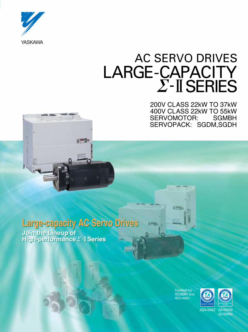
AC SERVO DRIVESLARGE-CAPACITY
SERIES200V CLASS 22kW TO 37kW400V CLASS 22kW TO 55kWSERVOMOTOR: SGMBHSERVOPACK: SGDM,SGDH
SeriesSeriesJoin the Lineup ofHigh-performanceJoin the Lineup ofHigh-performance
Large-capacity AC Servo DrivesLarge-capacity AC Servo Drives
widens the range of servo-control applications.widens the range of servo-control applications.
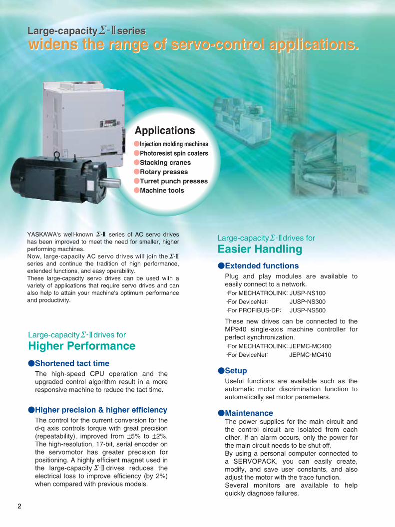
Applications
YASKAWA's well-known series of AC servo drives has been improved to meet the need for smaller, higher performing machines.Now, large-capacity AC servo drives will join theseries and continue the tradition of high performance, extended functions, and easy operability.These large-capacity servo drives can be used with a variety of applications that require servo drives and can also help to attain your machine's optimum performance and productivity.
Extended functionsPlug and play modules are available to easily connect to a network.·For MECHATROLINK: JUSP-NS100·For DeviceNet: JUSP-NS300·For PROFIBUS-DP: JUSP-NS500
These new drives can be connected to the MP940 single-axis machine controller for perfect synchronization. ·For MECHATROLINK: JEPMC-MC400·For DeviceNet: JEPMC-MC410
SetupUseful functions are available such as the automatic motor discrimination function to automatically set motor parameters.
MaintenanceThe power supplies for the main circuit and the control circuit are isolated from each other. If an alarm occurs, only the power for the main circuit needs to be shut off. By using a personal computer connected to a SERVOPACK, you can easily create, modify, and save user constants, and also adjust the motor with the trace function.Several monitors are available to help quickly diagnose failures.
Large-capacity seriesLarge-capacity series
Injection molding machinesPhotoresist spin coatersStacking cranesRotary pressesTurret punch pressesMachine tools
drives forLarge-capacity
Higher Performance
drives forLarge-capacity
Easier Handling
Shortened tact timeThe high-speed CPU operation and the upgraded control algorithm result in a more responsive machine to reduce the tact time.
Higher precision & higher efficiencyThe control for the current conversion for the d-q axis controls torque with great precision (repeatability), improved from ±5% to ±2%. The high-resolution, 17-bit, serial encoder on the servomotor has greater precision for positioning. A highly efficient magnet used in the large-capacity drives reduces the electrical loss to improve efficiency (by 2%) when compared with previous models.
2
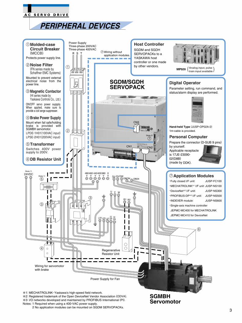
PERIPHERAL DEVICES
Power SupplyThree-phase 200VACThree-phase 400VAC
Wiring without application modules.
Wiring for servomotor with brake
Power Supply for Fan
1: MECHATROLINK−Yaskawa's high-speed field network.
2: Registered trademark of the Open DeviceNet Vendor Association (ODVA).
3: I/O networks developed and maintained by PROFIBUS International (PI).
Notes: 1 Required when using a 400-VAC power supply.2 No application modules can be mounted on SGDM SERVOPACKs.
Molded-caseCircuit Breaker(MCCB)
Protects power supply line.
Noise Filter(FN series made bySchaffner EMC Systems)
Mounted to prevent external electrical noise from the power line.
Magnetic Contactor(HI series made byYaskawa Controls Co., Ltd.)
ON/OFF servo power suppply. When applied, make sure to provide a coil serge suppresser.
Brake Power SupplyMount when fail safe/holding brake is provided with SGMBH servomotor. LPDE-1H01(100VAC input)LPSE-2H01(200VAC input)
TransformerSwitches 400V power supply to 200V.
DB Resistor Unit
1
2
3
4
5
6
Host ControllerSGDM and SGDH SERVOPACKs to a YASKAWA host controller or one made by other vendors.
7
Digital OperatorParameter setting, run command, and status/alarm display are performed.
Hand-held Type (JUSP-OP02A-2)
1m-cable is provided.
Personal ComputerPrepare the connector (D-SUB 9 pins)by yourself. Applicable receptacle is 17JE-23090-02(D8B)(made by DDK).
Application Modules·Fully closed I/F unit: JUSP-FC100
·MECHATROLINK1 I/F unit: JUSP-NS100
·DeviceNet2 I/F unit: JUSP-NS300
·PROFIBUS-DP3 I/F unit: JUSP-NS500
·INDEXER module: JUSP-NS600
·Single-axis machine controller
JEPMC-MC400 for MECHATROLINK
JEPMC-MC410 for DeviceNet
7
(Note 2)
CN3
CN1 CN2
RegenerativeResistor Unit
24VDC(Note 1)
(Note 1)
SGMBHServomotor
SGDM/SGDHSERVOPACK
3
SPECIFICATIONS
Speed (min-1) Speed (min-1) Speed (min-1)
Speed (min-1) Speed (min-1)
Torque(N·m) Torque(N·m)
Torque(N·m) Torque(N·m)
Torque(N·m)
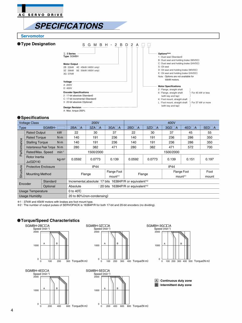
Type Designation
Specifications
Torque/Speed Characteristics
1 : 37kW and 45kW motors with brakes are foot mount type.
2 : The number of output pulses of SERVOPACK is 16384P/R for both 17-bit and 20-bit encoders (no dividing).
Voltage Class
Type SGMBH-
Encoder
Usage Temperature
Usage Humidity
Rated Output
Rated Torque
Stalling Torque
Instantaneous Peak Torque
Rated/Max. Speed
Rotor Inertia
JM(GD2/4)
Protective Enclosure
Mounting Method
Standard
Optional
kW
N·m
N·m
N·m
min-1
kg·m2
2BA A
22
140
140
280
0.0592
Incremental,absolute: 17 bits 16384P/R or equivalent2
Absolute : 20 bits 16384P/R or equivalent2
0 to 40 C
20 to 80%(non-condensing)
3GA A
37
236
236
471
0.139
Flange Foot
mount1
200V
3ZA A
30
191
191
382
1500/2000
0.0773
IP44
Flange FlangeFlange Foot
mount1
400V
3GD A
37
236
236
471
1500/2000
0.139
IP44
2BD A
22
140
140
280
0.0592
3ZD A
30
191
191
382
0.0773
4ED A
45
286
286
572
0.151
5ED A
55
350
350
700
0.197
Foot
mount
Per
form
ance
Str
uctu
re
SGMBH-2B A
SGMBH-4ED A SGMBH-5ED A
SGMBH-3Z A SGMBH-3G A
2000
1000
00 100 200 300
A B
2000
1000
00 100 200 300 400
A B A B
2000
1000
00 100 200 300 400 500
200 400 600 800
A B A B
2000
1000
00 200 400 600
2000
1000
00
SeriesType: SGMBH
Motor Output2B3Z3G
22kW30kW37kW
:::
4E5E
45kW55kW
(400V only)(400V only)
::
Options(Note)
Note : Options are not available for55kW motors.
1BCSDE
Dust seal (Standard)
Dust seal and holding brake (90VDC)
Dust seal and holding brake (24VDC)
Oil sealOil seal and holding brake (90VDC)
Oil seal and holding brake (24VDC)
::::::
Motor Specifications26
KL
Flange, straight shaftFlange, straight shaft(with key and tap)
Foot mount, straight shaftFoot mount, straight shaft(with key and tap)
For 45 kW or less
For 37 kW or more
::
::
Encoder Specifications2C3
17-bit absolute (Standard)
17-bit incremental (Standard)
20-bit absolute (Optional)
:::
VoltageAD
200V400V
::
Design RevisionA Max. torque 200%:
S G M B H - 2 B D 2 A
AB
::Continuous duty zoneIntermittent duty zone
Servomotor
4
Type Designation
Specifications
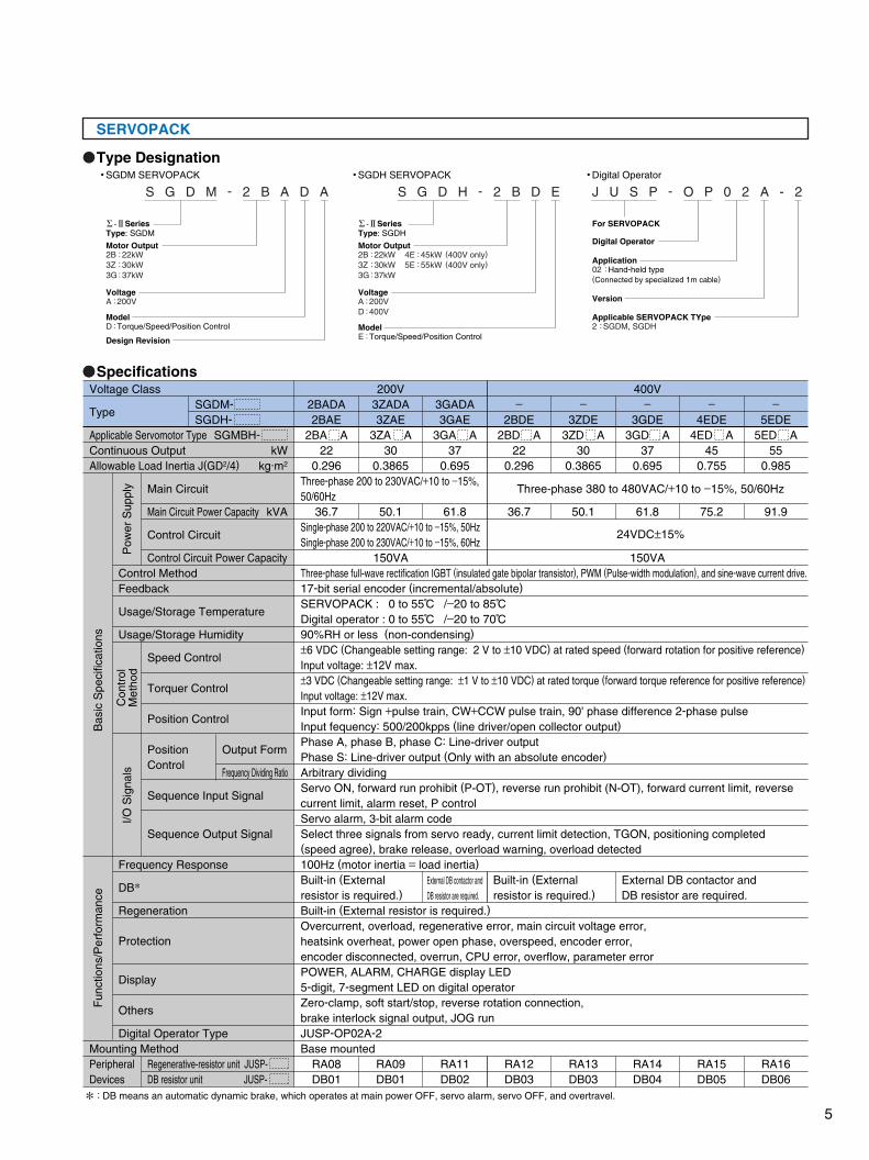
SGDM SERVOPACK SGDH SERVOPACK Digital Operator
: DB means an automatic dynamic brake, which operates at main power OFF, servo alarm, servo OFF, and overtravel.
2BADA2BAE
2BA A22
0.296
36.7
Three-phase 200 to 230VAC/+10 to −15%,50/60Hz
Three-phase 380 to 480VAC/+10 to −15%, 50/60Hz
24VDC±15%Single-phase 200 to 220VAC/+10 to −15%, 50HzSingle-phase 200 to 230VAC/+10 to −15%, 60Hz
Built-in (External resistor is required.)
External DB contactor and
DB resistor are required.
3GADA3GAE
3GA A37
0.695
61.8
−2BDE
2BD A22
0.296
36.7
RA08DB01
RA09DB01
RA11DB02
−3ZDE
3ZD A30
0.3865
50.1
−4EDE
4ED A45
0.755
75.2
−5EDE
5ED A55
0.985
91.9
200V3ZADA3ZAE
3ZA A30
0.3865
50.1
150VA
Voltage Class
Type
Applicable Servomotor TypeContinuous OutputAllowable Load Inertia J(GD2/4)
Mounting MethodPeripheral Devices
Main Circuit
Main Circuit Power Capacity
Control Circuit
Control Circuit Power CapacityControl MethodFeedback
Usage/Storage Temperature
Usage/Storage Humidity
Frequency Response
DB
Regeneration
Protection
Display
Others
Digital Operator Type
Regenerative-resistor unit JUSP-DB resistor unit JUSP-
SGDM-SGDH-
SGMBH-kW
kg·m2
kVA
400V−
3GDE3GD A
370.695
61.8
150VAThree-phase full-wave rectification IGBT (insulated gate bipolar transistor), PWM (Pulse-width modulation), and sine-wave current drive.17-bit serial encoder (incremental/absolute)SERVOPACK : 0 to 55 C /−20 to 85 CDigital operator : 0 to 55 C /−20 to 70 C90%RH or less (non-condensing)±6 VDC (Changeable setting range: 2 V to ±10 VDC) at rated speed (forward rotation for positive reference)Input voltage: ±12V max.±3 VDC (Changeable setting range: ±1 V to ±10 VDC) at rated torque (forward torque reference for positive reference)Input voltage: ±12V max.Input form: Sign +pulse train, CW+CCW pulse train, 90' phase difference 2-phase pulseInput fequency: 500/200kpps (line driver/open collector output)Phase A, phase B, phase C: Line-driver outputPhase S: Line-driver output (Only with an absolute encoder)Arbitrary dividingServo ON, forward run prohibit (P-OT), reverse run prohibit (N-OT), forward current limit, reverse current limit, alarm reset, P controlServo alarm, 3-bit alarm codeSelect three signals from servo ready, current limit detection, TGON, positioning completed(speed agree), brake release, overload warning, overload detected100Hz (motor inertia = load inertia)
Built-in (External resistor is required.)Overcurrent, overload, regenerative error, main circuit voltage error, heatsink overheat, power open phase, overspeed, encoder error, encoder disconnected, overrun, CPU error, overflow, parameter errorPOWER, ALARM, CHARGE display LED 5-digit, 7-segment LED on digital operatorZero-clamp, soft start/stop, reverse rotation connection, brake interlock signal output, JOG runJUSP-OP02A-2Base mounted
Built-in (External resistor is required.)
External DB contactor and DB resistor are required.
RA12DB03
RA13DB03
RA14DB04
RA15DB05
RA16DB06
Speed Control
Torquer Control
Position Control
PositionControl
Sequence Input Signal
Sequence Output Signal
Output Form
Frequency Dividing Ratio
Pow
er S
uppl
y
Bas
ic S
peci
ficat
ions
Fun
ctio
ns/P
erfo
rman
ce
Con
trol
Met
hod
I/O S
igna
ls
Motor Output2B3Z3G
22kW30kW37kW
:::
VoltageA 200V:
Model
Design Revision
D Torque/Speed/Position Control:
S G D M - 2 B A D A
Motor Output2B3Z3G
22kW30kW37kW
:::
4E5E
45kW55kW
(400V only)(400V only)
::
VoltageAD
200V400V
::
ModelE Torque/Speed/Position Control:
S G D H - 2 B D E
For SERVOPACK
Digital Operator
Application02 Hand-held type(Connected by specialized 1m cable)
:
Applicable SERVOPACK TYpe2 SGDM, SGDH:
Version
J U S P - O P 0 2 A - 2
SeriesType: SGDM
SeriesType: SGDH
SERVOPACK
5
+24V
P
0V
21
22
4
2
SEN
SG
BAT(+)
BAT(−)P
P
+−
FG
1MC
SUP
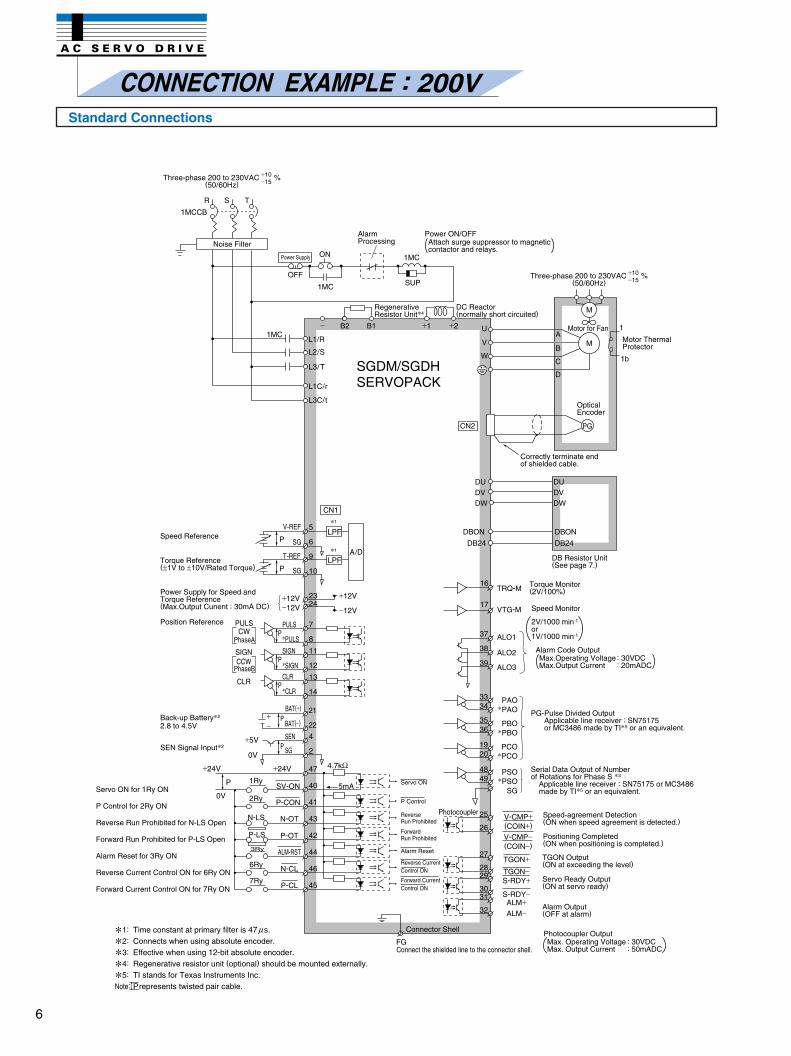
CONNECTION EXAMPLE : 200V
Three-phase 200 to 230VAC %(50/60Hz)
+10−15
Three-phase 200 to 230VAC %(50/60Hz)
+10−15
Noise Filter
Power Supply
Alarm Processing
DC Reactor(normally short circuited)
RegenerativeResistor Unit4
Motor for Fan
Motor ThermalProtector
OpticalEncoder
Correctly terminate endof shielded cable.
DB Resistor Unit(See page 7.)
Torque Monitor(2V/100%)
Speed Monitor
Alarm Code Output
PG-Pulse Divided OutputApplicable line receiver : SN75175 or MC3486 made by TI5 or an equivalent.
Serial Data Output of Number of Rotations for Phase S 3
Applicable line receiver : SN75175 or MC3486 made by TI5 or an equivalent.
Speed-agreement Detection (ON when speed agreement is detected.)
Positioning Completed (ON when positioning is completed.)
TGON Output(ON at exceeding the level)
Servo Ready Output(ON at servo ready)
Alarm Output(OFF at alarm)
Photocoupler Output
Connect the shielded line to the connector shell.
Servo ON
P Control
ReverseRun Prohibited
Reverse CurrentControl ON
ForwardRun Prohibited
Alarm Reset
Forward CurrentControl ON
Photocoupler
Connector Shell
SGDM/SGDHSERVOPACK
Speed Reference
Torque Reference(±1V to ±10V/Rated Torque)
Power Supply for Speed andTorque Reference(Max.Output Cunent : 30mA DC)
Position Reference
PhaseA
PhaseB
Back-up Battery2
SEN Signal Input2
2.8 to 4.5V
Servo ON for 1Ry ON
P Control for 2Ry ON
Reverse Run Prohibited for N-LS Open
Forward Run Prohibited for P-LS Open
Alarm Reset for 3Ry ON
Reverse Current Control ON for 6Ry ON
Forward Current Control ON for 7Ry ON
1: Time constant at primary filter is 47 s.
2: Connects when using absolute encoder.
3: Effective when using 12-bit absolute encoder.
4: Regenerative resistor unit (optional) should be mounted externally.
5: TI stands for Texas Instruments Inc.
Note: Prepresents twisted pair cable.
µMax. Operating Voltage : 30VDCMax. Output Current : 50mADC
Max.Operating Voltage : 30VDCMax.Output Current : 20mADC
2V/1000 min-1
or1V/1000 min-1
Power ON/OFFAttach surge suppressor to magnetic contactor and relays.
M
PG
A
B
C
D
M
1
1b
DUDVDW
DBON
DB24
DUDVDW
DBON
DB24
TRQ-M16
VTG-M
ALO1
ALO2
ALO3
17
37
38
39
PAOPAO
PBOPBO
PCOPCO
PSOPSO
SG
3334
3536
1920
4849
V-CMP+(COIN+)
25
26
27
2829
3031
32
V-CMP−(COIN−)
TGON+TGON−S-RDY+
S-RDY−ALM+ALM−
1Ry
2Ry
N-LS
P-LS
6Ry
7Ry
3Ry
+24V
SV-ON
P-CON
N-OT
P-OT
N-CL
P-CL
ALM-RST
47
40
41
43
42
44
46
45
4.7kΩ
5mA
+5V
0V
PULSCW
SIGN
CLR
CCW
PULS
PULSP
SIGN
SIGNP
CLR
CLRP
7
8
11
12
13
14
2324
+12V−12V
+12V
−12V
A/D
1
1
LPF
LPF
CN1
5
6
9
10
V-REF
SGP
T-REF
SGP
L3C/t
L1/R
L2/S
L3/T
L1C/r
1MC− B2 B1 +1 +2 U
V
W
OFF
1MC
ON
1MCCB
R S T
Standard Connections
6
DC Reactor
Three-phase200V
Regenerative Resistor
Power Board
DB Resistor UnitDB Contactor DB Resistor
Contactor Coil
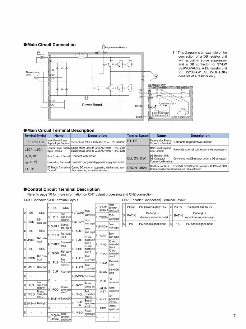
: This diagram is an example of the
connection of a DB resistor unit with a built-in surge suppressor and a DB contactor for 37-kW SERVOPACKs. A DB resistor unit for 22/30-kW SERVOPACKs consists of a resistor only.
Surge Suppressor for Contactor Coil
Surge Suppressor
Terminal Symbol Name Description DescriptionTerminal Symbol
Three-phase 200V to 230VAC/+10 to −15%, 50/60HzL1/R, L2/S, L3/T
L1C/r, L3C/t
U, V, W
Single-phase 200V to 220VAC/+10 to −15%, 50HzSingle-phase 200V to 230VAC/+10 to −15%, 60Hz
Connect with motor.
Grounded (for grounding power supply and motor).
Connect DC reactor for suppressing high-harmonic wave. If not necessary, shorten the terminals.
−
+1, +2
B1, B2
DBON, DB24
DU, DV, DW,
Refer to page 10 for more information on CN1 output processing and CN2 connection.
CN1 (Connector I/O) Terminal Layout CN2 (Encoder Connection) Terminal Layout
2
4
6
8
10
12
14
16
18
20
22
24
1
3
5
7
9
11
13
15
17
19
21
23
25
26
28
30
32
34
36
38
40
42
44
46
48
50
27
29
31
33
35
37
39
41
43
45
47
49
GND
SEN signal input
Ref. pulseinput
Ref. pulseinput
Speedref. input
TGONoutput signal TGON
output signalServoready output Servo
ready outputServoalarm output Servo
alarm outputPG pulse divided output phase A PG pulse
divided output phase APG pulse
divided output phase B PG pulse
divided outputphase B
Rev. sideovertravel input
Phase Ssignal output
Phase Ssignal output
Servo ONinput
Fwd.overtravel input
Alarmreset input
Rev.current limitON input
−
Fwd.current limitON inputExternalinput powersupply
P control input
Alarm code output
Alarm code output
Alarm codeoutput
Ref. codeinput
−
−
Battery(−)
Battery(+)
Clear input
Clear input
PG pulse divided outputphase C
PG pulse divided outputphase C
Powersupply for opencollector ref.
Powersupply for opencollector ref.
PowerSupply for opencollector ref.
GND
GND
GND
Torque ref.input
Ref. codeinput
−
−
Speedagreementsignal output
Speedagreementsignal output
1
3
5
2
4
6
PG5V PG power supply +5V PG 0V PG power supply 0V
BAT(+)Battery(+)
(absolute encoder only) BAT(−)Battery(−)
(absolute encoder only)
PS PG serial signal input /PS PG serial signal input
Main Circuit Power Supply Input Terminal
Control Power Supply Input Terminal
DC Reactor Connection Terminal
Motor Connection Terminal
Grounding Terminal
NameRegenerative ResistorConnection Terminal
Main Circuit Negative Side Terminal
DB Resistor Unit, DB Contactor ConnectionTerminal
DB Resistor Unit ConnectionTerminal
Connects regenerative resistor.
(Normally external connection is not necessary.)
Connected to a DB resistor unit or a DB contactor.
For 37kW SERVOPACK, connect to DBON and DB24 terminals of DB resistor unit.
(× 2)
SG
SEN
SG
/PULS
SG
/SIGN
/CLR
−
PL3
/PCO
BAT(−)
−
SG
PL1
V-REF
PULS
T-REF
SIGN
PL2
CLR
−
PCO
BAT(+)
−
/V-CMP+(/COIN+)
/TGON+
/S-RDY+
ALM+
PAO
PBO
ALO1
ALO3
/P-CON
N-OT
/P-CL
/PSO
+24V-IN
/V-CMP(/COIN-)
/ALM-RST
/TGON-
/S-RDY-
ALM-
/PAO
/PBO
ALO2
/S-ON
P-OT
/N-CL
PSO
−
+1
+2
L2/S
L1/R
L3/T
L1C/r
−
L3C/t
B1B2
M
U
V
W
DU
DV
DW
DU
DV
DW
DBON
DB24
DBON
DB24
Main Circuit Connection
Main Circuit Terminal Description
Control Circuit Terminal Description
7
Noise Filter
Power Supply
DC Reactor(normally short circuited)
RegenerativeResistor Unit4
Motor for FanMotor ThermalProtector
OpticalEncoder
Correctly terminate endof shielded cable.
DB Resistor Unit(See page 9.)
Torque Monitor(2V/100%)
Speed-agreement Detection (ON when speed agreement is detected.)
Positioning Completed (ON when positioning is completed.)
TGON Output(ON at exceeding the level)
Servo Ready Output(ON at servo ready)
Alarm Output(OFF at alarm)
Connector Shell
Connect the shielded line to the connector shell.
Servo ON
P Control
ReverseRun Prohibited
Reverse CurrentControl ON
ForwardRun Prohibited
Alarm Reset
Forward CurrentControl ON
Photocoupler
Speed Reference
Torque Reference(±1V to ±10V/Rated Torque)
Power Supply for Speed andTorque Reference(Max.Output Cunent : 30mA DC)
Position Reference
Back-up Battery2
SEN Signal Input2
2.8 to 4.5V
Servo ON for 1Ry ON
P Control for 2Ry ON
Reverse Run Prohibited for N-LS Open
Forward Run Prohibited for P-LS Open
Alarm Reset for 3Ry ON
Reverse Current Control ON for 6Ry ON
Forward Current Control ON for 7Ry ON
Control Power Supply24 VDC(Provided by user.)
SGDH SERVOPACK
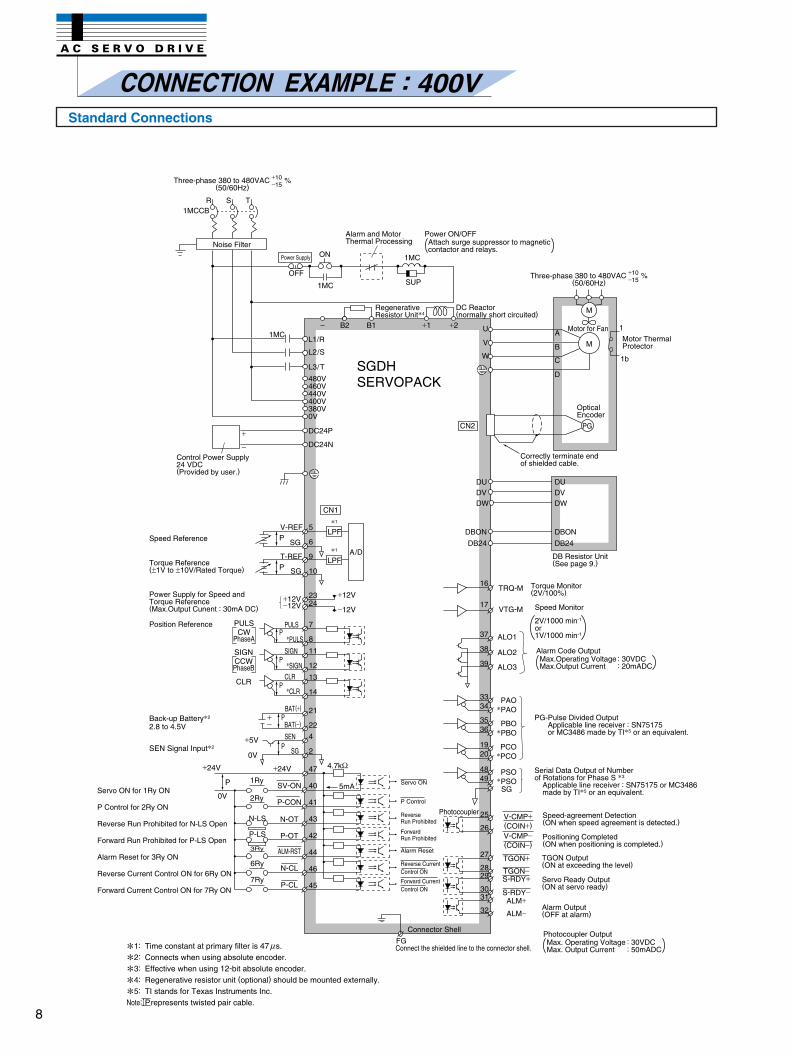
Three-phase 380 to 480VAC %(50/60Hz)
+10−15
Three-phase 380 to 480VAC %(50/60Hz)
+10−15
1: Time constant at primary filter is 47 s.
2: Connects when using absolute encoder.
3: Effective when using 12-bit absolute encoder.
4: Regenerative resistor unit (optional) should be mounted externally.
5: TI stands for Texas Instruments Inc.
Note: Prepresents twisted pair cable.
µPhotocoupler OutputMax. Operating Voltage : 30VDCMax. Output Current : 50mADC
Serial Data Output of Number of Rotations for Phase S 3
Applicable line receiver : SN75175 or MC3486 made by TI5 or an equivalent.
PG-Pulse Divided OutputApplicable line receiver : SN75175 or MC3486 made by TI5 or an equivalent.
Speed Monitor
Alarm Code OutputMax.Operating Voltage : 30VDCMax.Output Current : 20mADC
2V/1000 min-1
or1V/1000 min-1
1MCCB R S T
OFF
ON
1MC
1MC
SUP
− B2 B1 +1 +2 U
V
W
L1/R
L2/S
L3/T
480V460V440V400V380V0V
DC24N
DC24P
1MC
+
−
CN1
A/D
1
LPF
1
LPF
5
6
9
10
V-REF
SGP
T-REF
SGP
2324
+12V−12V
+12V
−12V
PULSCW
PhaseA
SIGN
CLR
CCWPhaseB
7
8
11
12
13
14
PULS
PULSP
SIGN
SIGNP
CLR
CLRP
+24V
P
0V
1Ry
2Ry
N-LS
P-LS
6Ry
7Ry
3Ry
+24V
SV-ON
P-CON
N-OT
P-OT
N-CL
P-CL
ALM-RST
+5V
0V
21
22
4
2
SEN
SG
BAT(+)
BAT(−)P
P
+−
47
40
41
43
42
44
46
45
4.7kΩ
5mA
FG
V-CMP+(COIN+)
25
26
27
2829
3031
32
V-CMP−(COIN−)
TGON+
TGON−S-RDY+
S-RDY−ALM+
ALM−
PAOPAO
PBOPBO
PCOPCO
PSOPSO
SG
3334
3536
1920
4849
TRQ-M16
VTG-M
ALO1
ALO2
ALO3
17
37
38
39
DUDVDW
DBON
DB24
DUDVDW
DBON
DB24
M
A
B
C
D
M
PG
1
1b
Alarm and Motor Thermal Processing
Power ON/OFFAttach surge suppressor to magnetic contactor and relays.
CONNECTION EXAMPLE : 400VStandard Connections
8
M
B1B2
U
V
Regenerative Resistor
W
Power Board
DCReactor
Three-phase400V
24VDC
480V 460V 440V 400V 380V 0V
DB Contactor DB Resistor
Contactor Coil
Surge Suppressorfor Contactor Coil
Surge Suppressor
DB Resistor Unit
Connect to the terminal whosevoltage is close to the powersupply voltage.
Refer to page 10 for more information on CN1 output processing and CN2 connection.
CN1 (Connector I/O) Terminal Layout CN2 (Encoder Connection) Terminal Layout
2
4
6
8
10
12
14
16
18
20
22
24
1
3
5
7
9
11
13
15
17
19
21
23
25
26
28
30
32
34
36
38
40
42
44
46
48
50
27
29
31
33
35
37
39
41
43
45
47
49
GND
SEN signal input
Ref. pulseinput
Ref. pulseinput
Speedref. input
TGONoutput signal TGON
output signalServoready output Servo
ready outputServoalarm output Servo
alarm outputPG pulse divided output phase A PG pulse
divided output phase APG pulse
divided output phase B PG pulse
divided output phase B
Rev. sideovertravel input
Phase Ssignal output
Phase Ssignal output
Servo ONinput
Fwd.overtravel input
Alarmreset input
Rev.current limitON input
−
Fwd.current limitON inputExternalinput powersupply
P control input
Alarm code output
Alarm code output
Alarm codeoutput
Ref. codeinput
−
−
Battery(−)
Battery(+)
Clear input
Clear input
PG pulse divided outputphase C
PG pulsedivided outputphase C
Powersupply for opencollector ref.
Powersupply for opencollector ref.
PowerSupply for opencollector ref.
GND
GND
GND
Torque ref.input
Ref. codeinput
−
−
Speedagreementsignal output
Speedagreementsignal output
1
3
5
2
4
6
PG5V PG power supply +5V PG 0V PG power supply 0V
BAT(+)Battery(+)
(absolute encoder only) BAT(−)Battery(−)
(absolute encoder only)
PS PG serial signal input /PS PG serial signal input
L2/S
L1/R
L3/T
DC24P
DC24N
DU
DV
DW
DBON
DB24
DBON
DB24
DU
DV
DW
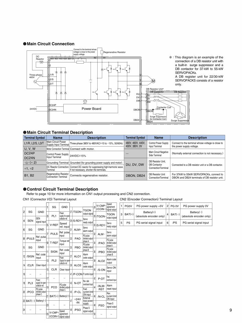
: This diagram is an example of the
connection of a DB resistor unit with a built-in surge suppressor and a DB contactor for 37-kW to 55-kW SERVOPACKs. A DB register unit for 22/30-kW SERVOPACKS consists of a resistor only.
Main Circuit Power Supply Input Terminal
Motor Connection Terminal
Control Power Supply Input Terminal
Grounding Terminal Grounded (for grounding power supply and motor).
DC Reactor Connection Terminal
Connect DC reactor for suppressing high-harmonic wave. If not necessary, shorten the terminals.
Regenerative ResistorConnection Terminal Connects regenerative resistor.
Three-phase 380V to 480VAC/+10 to −15%, 50/60Hz
Connect with motor.
24VDC±15%
SG
SEN
SG
/PULS
SG
/SIGN
/CLR
−
PL3
/PCO
BAT(−)
−
SG
PL1
V-REF
PULS
T-REF
SIGN
PL2
CLR
−
PCO
BAT(+)
−
/V-CMP+(/COIN+)
/TGON+
/S-RDY+
ALM+
PAO
PBO
ALO1
ALO3
/P-CON
N-OT
/P-CL
/PSO
+24V-IN
/V-CMP−(/COIN−)
/ALM-RST
/TGON−
/S-RDY−
ALM−
/PAO
/PBO
ALO2
/S-ON
P-OT
/N-CL
PSO
−
Terminal Symbol Name Description
L1/R, L2/S, L3/T
U, V, WDC24PDC24N
+1, +2
B1, B2
(× 2)
Main Circuit Connection
Main Circuit Terminal Description
Control Circuit Terminal Description
−
+1
+2
Terminal Symbol Name
Control Power Supply Input Terminal
Description
Connect to the terminal whose voltage is close to the power supply voltage.
Connected to a DB resistor unit or a DB contactor.
For 37kW to 55kW SERVOPACKs, connect to DBON and DB24 terminals of DB resistor unit.
(Normally external connection is not necessary.)
480V, 460V, 440V, 400V, 380V, 0V
DU, DV, DW
DBON, DB24
− Main Circuit Negative Side Terminal
DB Resistor Unit ConnectionTerminal
DB Resistor Unit, DB Contactor ConnectionTerminal
9
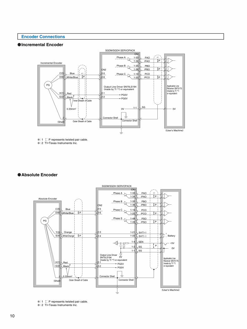
Encoder Connections
Incremental Encoder
Absolute Encoder
Incremental Encoder
Blue
Red
Black
White/Blue
PG
C(5) 2-5
2-6
2-1
2-2
CN2
1-33
1-34
1-35
1-36
1-19
1-20
CN1
D(6)
H(1)
G(2)
J
P
(Shell)
Connector Shell
PG5V
Phase A PAO
/PAO
PBO
/PBO
PCO
/PCO
Phase B
Phase C
PG0V
Connector Shell
(User's Machine)
0V 0V1-1 SG
SGDM/SGDH SERVOPACK
P
P
P
Outer Sheath of Cable
Inner Sheath of CableInner Sheath of Cable
Output Line Driver SN75LS194(made by TI 2) or equivalent
Applicable Line Receiver SN75175(made by TI 2) or equivalent
1
1
: 1 P represents twisted pair cable.
: 2 TI=Texas Instruments Inc.
: 1 P represents twisted pair cable.
: 2 TI=Texas Instruments Inc.
0.33mm2
SG
SEN
SG
SGDM/SGDH SERVOPACK
Outer Sheath of Cable
Absolute Encoder
PG
Blue
Red
Black
White/Blue
White/Orange
Orange
C(5)
D(6)
T(3)
S(4)
H(1)
G(2)
J 0.33mm2
(Shell)
(User's Machine)
0V
+5V
0V
BAT(+)
BAT(−)
P
+− Battery
Phase A
Phase B
Phase C
Phase S
Applicable Line Receiver SN75175(made by TI 2) or equivalent
P
P
P
P
P
P
1
Connector Shell
Connector Shell
2-5
2-3
2-4
2-1
2-2
2-6
CN2
Output Line DriverSN75LS194(made by TI 2) or equivalent
PG5V
PG0V
1-33
1-34
CN1
PAO
/PAO
1-35
1-36PBO
/PBO
1-19
1-20PCO
/PCO
1-48
1-49
1-21
1-22
1-4
1-2
1-1
PSO
/PSO
10
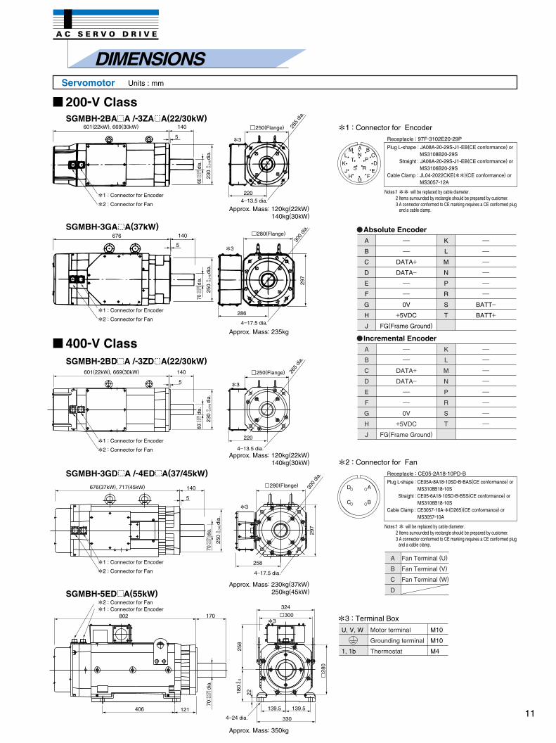
DIMENSIONSServomotor Units : mm
A
B
C
D
Fan Terminal (U)
Fan Terminal (V)
Fan Terminal (W)
3 : Terminal Box
200-V Class
400-V Class
601(22kW), 669(30kW) 140
5
258
297
140
5
676(37kW), 717(45kW)
406 121
802 170
330
139.5 139.5
324
258
180
-0.50
22
3
3
3
220
Approx. Mass: 120kg(22kW)140kg(30kW)
Approx. Mass: 120kg(22kW)140kg(30kW)
Approx. Mass: 230kg(37kW)250kg(45kW)
Approx. Mass: 350kg
Approx. Mass: 235kg
2204−13.5 dia.
4−17.5 dia.
4−13.5 dia.
4−17.5 dia.
4−24 dia.
265
dia.
601(22kW), 669(30kW) 140
5
1 : Connector for Encoder
2 : Connector for Fan
1 : Connector for Encoder
2 : Connector for Fan
1 : Connector for Encoder
2 : Connector for Fan
1 : Connector for Encoder
1 : Connector for Encoder
2 : Connector for Fan
2 : Connector for Fan
3
286
676 140
5
3
SGMBH-2BA A /-3ZA A(22/30kW)
SGMBH-2BD A /-3ZD A(22/30kW)
SGMBH-3GD A /-4ED A(37/45kW)
SGMBH-5ED A(55kW)
SGMBH-3GA A(37kW)
250(Flange)
280(Flange)
250(Flange)
280(Flange)
297
280
300
60di
a.+ 0
.030
+ 0.0
11
230
dia.
0.
− 0.0
46
70di
a.+ 0
.030
+ 0.0
11
250
dia.
0.
− 0.0
46
60di
a.+ 0
.030
+ 0.0
11
230
dia.
0.
− 0.0
4670
dia.
+ 0.0
30+ 0
.011
70di
a.+ 0
.030
+ 0.0
11
250
dia.
0.
− 0.0
46
300
dia.
265
dia.
300
dia.
1 : Connector for Encoder
Plug L-shape : JA08A-20-29S-J1-EB(CE conformance) orMS3108B20-29S
Straight : JA06A-20-29S-J1-EB(CE conformance) orMS3106B20-29S
Cable Clamp : JL04-2022CKE(
)(CE conformance) orMS3057-12A
Receptacle : 97F-3102E20-29P
Notes:1
will be replaced by cable diameter.2 Items surrounded by rectangle should be prepared by customer.3 A connector conformed to CE marking requires a CE conformed plug
and a cable clamp.
Plug L-shape : CE05A-8A18-10SD-B-BAS(CE conformance) orMS3108B18-10S
Straight : CE05-6A18-10SD-B-BSS(CE conformance) orMS3106B18-10S
Cable Clamp : CE3057-10A-
(D265)(CE conformance) orMS3057-10A
Receptacle : CE05-2A18-10PD-B
Notes:1
will be replaced by cable diameter.2 Items surrounded by rectangle should be prepared by customer.3 A connector conformed to CE marking requires a CE conformed plug
and a cable clamp.
2 : Connector for Fan
Absolute Encoder
Incremental Encoder
A
B
C
D
E
F
G
H
J
K
L
M
N
P
R
S
T
−−
DATA+
DATA−−−
0V
+5VDC
FG(Frame Ground)
−−−−−−
BATT−
BATT+
A
B
C
D
E
F
G
H
J
K
L
M
N
P
R
S
T
−−
DATA+
DATA−−−
0V
+5VDC
FG(Frame Ground)
−−−−−−−−
U, V, W
1, 1b
M10
M10
M4
Motor terminal
Grounding terminal
Thermostat
AN
PT
S R
BM
DKEJ
FHG
CL
D
C
A
B
11
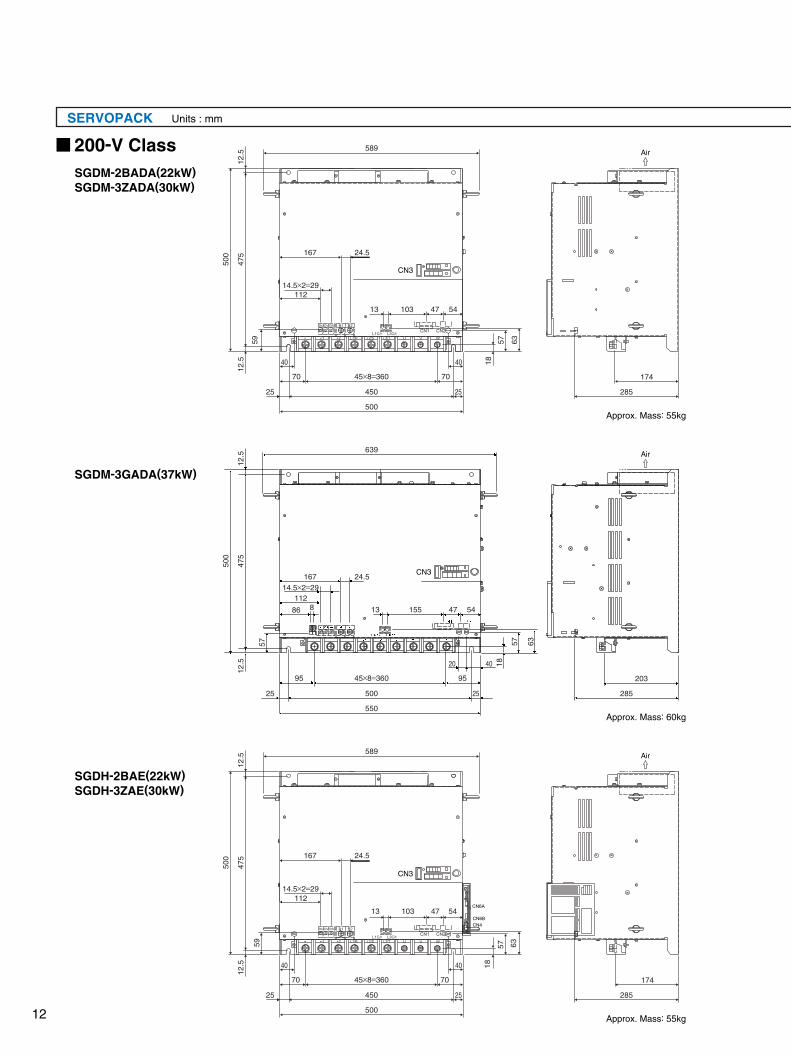
SERVOPACK Units : mm
200-V ClassSGDM-2BADA(22kW)SGDM-3ZADA(30kW)
SGDH-2BAE(22kW)SGDH-3ZAE(30kW)
SGDM-3GADA(37kW)
Approx. Mass: 55kg
Approx. Mass: 60kg
Approx. Mass: 55kg
589
639
589
12.5
12.5
59 6357
18
475
500
12.5
12.5
475
500
167
4713 103 54
112
40 40
70 7045×8=360
450
500
25 25
174
285
203
285
174
285
14.5×2=29
24.5
Air
Air
Air
57
20 40
95 9545×8=360
500
550
25 25
6357
18
6357
18
4713 155 54
4713 103 54
167
112
86 8
14.5×2=29
11214.5×2=29
24.5
167 24.5
4040
70 7045×8=360
450
500
25 25
12.5
12.5
475
500
59
CN3
CN3
CN3
12
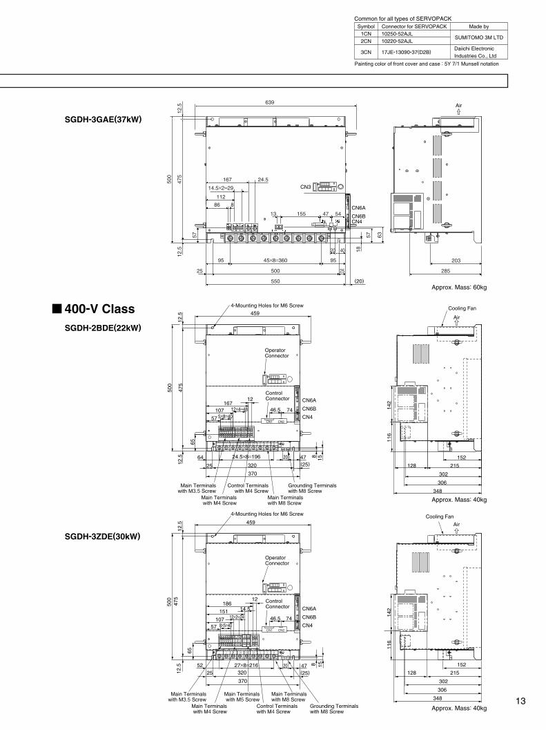
400-V ClassSGDH-2BDE(22kW)
SGDH-3ZDE(30kW)
SGDH-3GAE(37kW)
CN3
459
151
12
10757 8×5=40
5225 320
370
20 47(25)
500
475
12.5
65
8 15
18614.5
12×2=24 46.5 74
12.5
27×8=216
24.5×8=196
OperatorConnector
4-Mounting Holes for M6 Screw
4-Mounting Holes for M6 Screw
CN6A
CN6BCN4
CN6A
CN6B
CN4
CN6A
CN6B
CN4
459
12
57
12×4=485×8=40
64
25 320
370
20 47(25)12
.547
512
.5
65
8 15
116
142
128
152
215
302
306
348
116
142
128
152
215
302
306
348
500
167107 7446.5
NS100
+2+1− L1/R L2/S L3/T U V W
CN3
CN2CN1
Air
DU DWDV B1 DC24N
480V
460V
440V
400V
380V
0V
DC24PB2
OperatorConnector
ControlConnector
ControlConnector
Main Terminalswith M3.5 Screw
Control Terminalswith M4 Screw
Grounding Terminalswith M8 Screw
Main Terminalswith M4 Screw
Main Terminalswith M8 Screw
Main Terminalswith M3.5 Screw
Main Terminalswith M5 Screw
Main Terminalswith M8 Screw
Main Terminalswith M4 Screw
Control Terminalswith M4 Screw
Grounding Terminalswith M8 Screw
Cooling Fan
Air
Cooling Fan
Approx. Mass: 60kg
Approx. Mass: 40kg
Approx. Mass: 40kg
Air639
12.5
12.5
57 57 63
18
475
500
167
4713 155 54
112
86 8
20 40
95 9545×8=360
500
550 (20)
25 25
14.5×2=29
24.5
203
285
+2+1− L1/R L2/S L3/T U V W
CN2CN1
DU DWDV B1 DC24N
480V
460V
440V
400V
380V
0V
DC24PB2
NS100
CN3
Painting color of front cover and case : 5Y 7/1 Munsell notation
Common for all types of SERVOPACKSymbol
1CN2CN
3CN
Connector for SERVOPACK10250-52AJL10220-52AJL
17JE-13090-37(D2B)
Made by
SUMITOMO 3M LTD
Daiichi ElectronicIndustries Co., Ltd
13
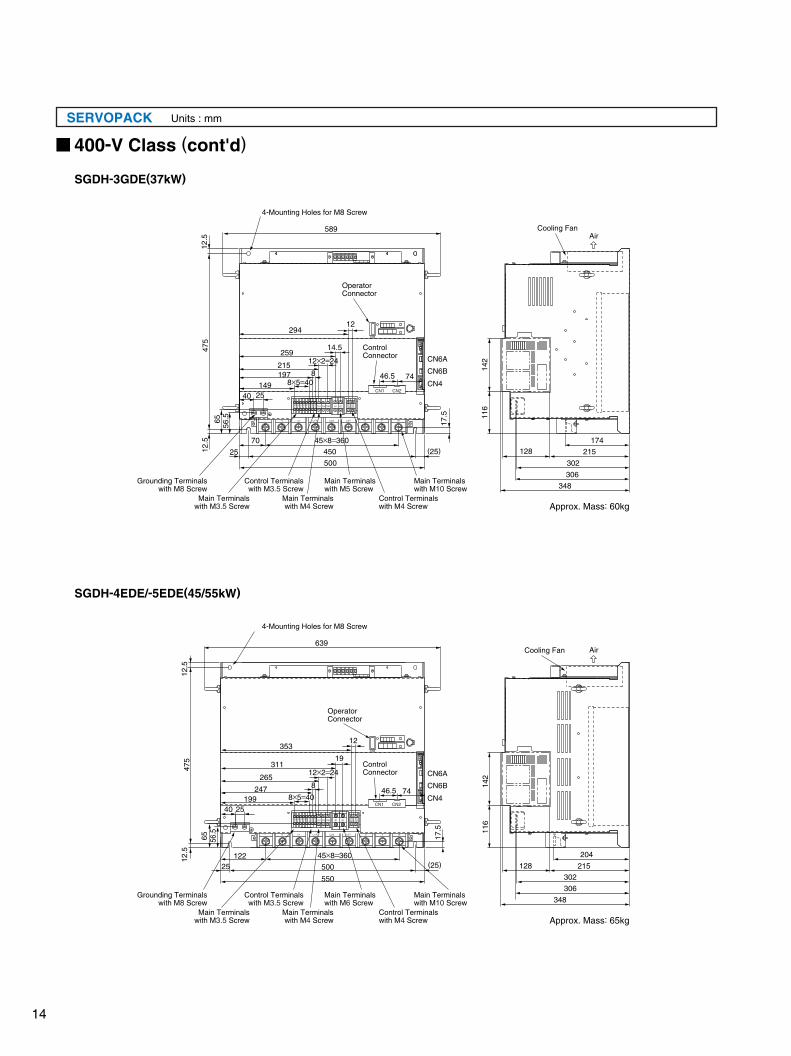
SERVOPACK Units : mm
1 2 3 4
CN3
CN3
CN6A
CN6B
CN4
CN6A
CN6B
CN4
NS100
1 2 3 4
NS100
639
35312
265
247
12×2=24
8×5=40
19
25 500
550
40 25
8
(25)
56.5
475
12.5
65 17.5 11
614
2
128
204
215
302
306
348
12.5
122
19946.5 74
259
215197
12×2=24
8×5=40
14.5
25 450
500
40
8
(25)
56.5
475
12.5
65 17.5
70
14925
46.5 74
302
306
34811
614
2
128174
215
12.5
589
12
45×8=36045×8=360
294
311
4-Mounting Holes for M8 Screw
OperatorConnector
OperatorConnector
ControlConnector
4-Mounting Holes for M8 Screw
ControlConnector
Approx. Mass: 60kg
Approx. Mass: 65kg
AirCooling Fan
AirCooling Fan
SGDH-3GDE(37kW)
SGDH-4EDE/-5EDE(45/55kW)
+2+1− L1/R L2/S L3/T U V W
CN2CN1
CN2CN1
DU DV DW DC24N
480V
460V
440V
400V
380V
0V
DBON
DB24
DC24PB1 B2
+2+1− L1/R L2/S L3/T U V W
DU DV DW DC24N
480V
460V
440V
400V
380V
0V
DBON
DB24
DC24PB1 B2
45×8=36045×8=360
400-V Class (cont'd)
Grounding Terminalswith M8 Screw
Control Terminalswith M3.5 Screw
Main Terminalswith M5 Screw
Main Terminalswith M10 Screw
Main Terminalswith M3.5 Screw
Main Terminalswith M4 Screw
Control Terminalswith M4 Screw
Grounding Terminalswith M8 Screw
Control Terminalswith M3.5 Screw
Main Terminalswith M6 Screw
Main Terminalswith M10 Screw
Main Terminalswith M3.5 Screw
Main Terminalswith M4 Screw
Control Terminalswith M4 Screw
14
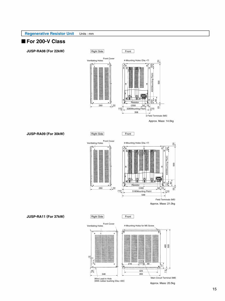
Regenerative Resistor Unit Units : mm
Approx. Mass: 21.0kg
Approx. Mass: 20.5kg
Right Side Front
Right Side Front
Right Side Front
Main Circuit Terminal (M8)
( 5)260 (5)
500
400(
Mou
ntin
g P
itch)
( 50)
( 50)
( 5)
518(Mounting Pitch)
548
(446) 7032(15)
Field Terminals (M5)
83
Resistor
348 484425
216 49
45
37
Wire Lead-in Hole[With rubber bushing (Dia.=33)]
500
77
7.5
485
Approx. Mass: 14.0kg
260 (5)
500
400(
Mou
ntin
g P
itch)
( 50)
( 5)
( 50)
328(Mounting Pitch) ( 5)
358
(256) 7032(15)
(15)
(15)
3 Field Terminals (M5)
83
Resistor
Ventilating HolesFront Cover
For 200-V Class
JUSP-RA08 (For 22kW)
JUSP-RA09 (For 30kW)
JUSP-RA11 (For 37kW)
4-Mounting Holes (Dia.=7)
Ventilating HolesFront Cover
4-Mounting Holes (Dia.=7)
Ventilating HolesFront Cover
4-Mounting Holes for M5 Screw
15
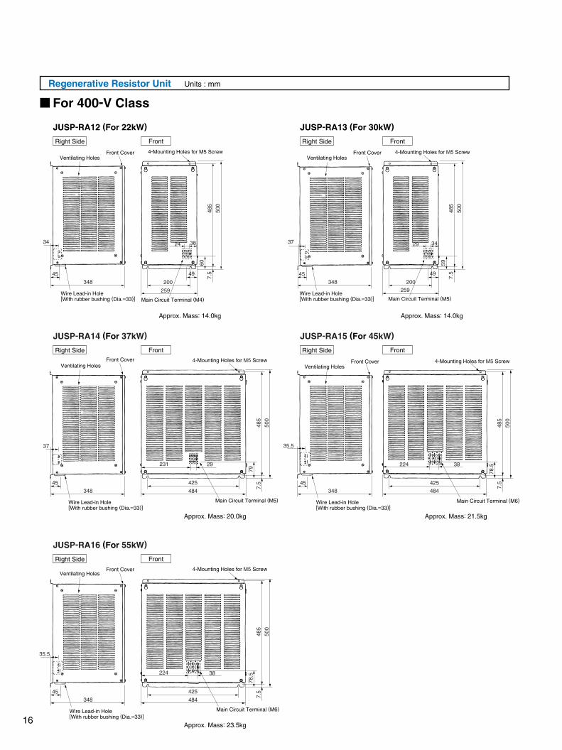
Regenerative Resistor Unit Units : mm
Approx. Mass: 14.0kg
Approx. Mass: 20.0kg
Approx. Mass: 23.5kg
Approx. Mass: 14.0kg
Approx. Mass: 21.5kg
JUSP-RA12 (For 22kW)
484
425
29
500
485
79
7.5
500
485
78.5
7.5
348
45
34
348
45
37
348
45
45
37
500
485
607.
5
500
485
597.
5
24 38
259
200
49
29 34
259
200
484
425
224 38
500
78.5
7.5
485
224 38
35.5
49
231
Front
Front
Front
JUSP-RA13 (For 30kW)
Front
JUSP-RA14 (For 37kW) JUSP-RA15 (For 45kW)
JUSP-RA16 (For 55kW)
Ventilating HolesFront Cover
Ventilating HolesFront Cover4-Mounting Holes for M5 Screw
Ventilating HolesFront Cover 4-Mounting Holes for M5 Screw
Ventilating HolesFront Cover 4-Mounting Holes for M5 Screw
4-Mounting Holes for M5 Screw
Ventilating HolesFront Cover 4-Mounting Holes for M5 Screw
Main Circuit Terminal (M4) Main Circuit Terminal (M5)
Main Circuit Terminal (M5)
484
425
Main Circuit Terminal (M6)
Main Circuit Terminal (M6)
For 400-V Class
Wire Lead-in Hole[With rubber bushing (Dia.=33)]
Wire Lead-in Hole[With rubber bushing (Dia.=33)]
Wire Lead-in Hole[With rubber bushing (Dia.=33)]
Wire Lead-in Hole[With rubber bushing (Dia.=33)]
348
35.5
Wire Lead-in Hole[With rubber bushing (Dia.=33)]
348
45
Right Side
Right Side
Right Side
FrontRight Side
Right Side
16
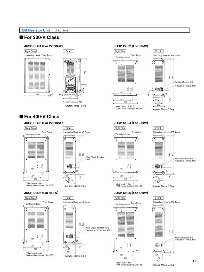
DB Resistor Unit Units : mm
Approx. Mass: 5.0kg
Approx. Mass: 5.0kg
Approx. Mass: 6.0kg
JUSP-DB01 (For 22/30kW) JUSP-DB02 (For 37kW)
JUSP-DB03 (For 22/30kW) JUSP-DB04 (For 37kW)
JUSP-DB05 (For 45kW) JUSP-DB06 (For 55kW)
Front CoverVentilating HolesVentilating Holes
Front Cover
Ventilating HolesFront Cover 4-Mounting Holes for M5 Screw
Ventilating HolesFront Cover 4-Mounting Holes for M5 Screw
Ventilating HolesFront Cover 4-Mounting Holes for M5 Screw
Ventilating HolesFront Cover
Approx. Mass: 6.0kg
Approx. Mass: 6.0kg
Approx. Mass: 7.0kg
255 (5) (10) (10)
350
290(
Mou
ntin
g P
itch)
( 30)
( 30)
50
DU DV DW
130(Mounting Pitch)
150
4 Field Terminals (M5)
Resistor
259
187
187
400
385
7371.5
7.5
400
385
73
7.5
Main Circuit Terminal (M5)
Main Circuit Terminal (M4)
Control-circuit Terminal (M3.5)
Main Circuit Terminal (M4)Control-circuit Terminal (M3.5)
Main Circuit Terminal (M4)Control-circuit Terminal (M3.5)
12475
62
259
187
184
184
400
385
73
7.5
12475
62
400
385
73
7.5
12475
62
12475
62
12475
62
184
490
475
73
7.5
184
For 200-V Class
For 400-V Class
Wire Lead-in Hole[With rubber bushing (Dia.=33)]
Wire Lead-in Hole[With rubber bushing (Dia.=33)]
259
187
Wire Lead-in Hole[With rubber bushing (Dia.=33)]
259
187
Wire Lead-in Hole[With rubber bushing (Dia.=33)]
259
187
Wire Lead-in Hole[With rubber bushing (Dia.=33)]
Right Side
Right Side
Right Side
Right Side
Right Side Right Side
Front Front
Front Front
Front Front
Main Circuit Terminal (M4)Control-circuit Terminal (M3.5)
4-Mounting Holes for M5 Screw
4-Mounting Holes for M5 Screw
17
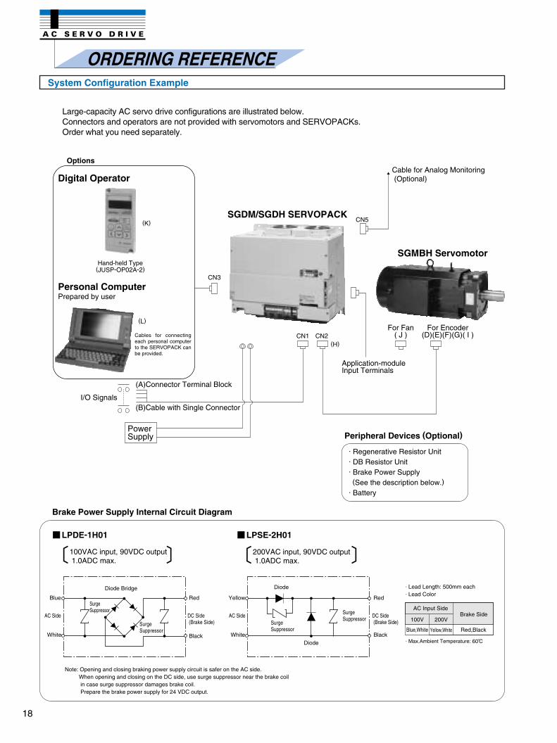
System Configuration Example
ORDERING REFERENCE
Large-capacity AC servo drive configurations are illustrated below.Connectors and operators are not provided with servomotors and SERVOPACKs. Order what you need separately.
Cables for connecting each personal computer to the SERVOPACK can be provided.
(A)Connector Terminal Block
(B)Cable with Single ConnectorI/O Signals
PowerSupply
Cable for Analog Monitoring(Optional)
For Encoder(D)(E)(F)(G)( I )
For Fan( J )
SGMBH Servomotor
SGDM/SGDH SERVOPACK
Application-module Input Terminals
100VAC input, 90VDC output1.0ADC max.
200VAC input, 90VDC output1.0ADC max.
Note: Opening and closing braking power supply circuit is safer on the AC side. When opening and closing on the DC side, use surge suppressor near the brake coil in case surge suppressor damages brake coil. Prepare the brake power supply for 24 VDC output.
AC Input SideBrake Side
100V 200V
Blue,White Yellow,White Red,Black
· Lead Length: 500mm each· Lead Color
· Max.Ambient Temperature: 60 C
Diode Bridge
Diode
Diode
Blue
White
AC Side
Yellow
White
AC Side
Red
Black
SurgeSuppressor
SurgeSuppressor
SurgeSuppressor
DC Side(Brake Side)
Red
Black
DC Side(Brake Side)
SurgeSuppressor
Brake Power Supply Internal Circuit Diagram
LPDE-1H01 LPSE-2H01
Peripheral Devices (Optional)
· Regenerative Resistor Unit· DB Resistor Unit· Brake Power Supply(See the description below.)
· Battery
Hand-held Type(JUSP-OP02A-2)
Options
Digital Operator
Personal ComputerPrepared by user
(K)
(L)
18
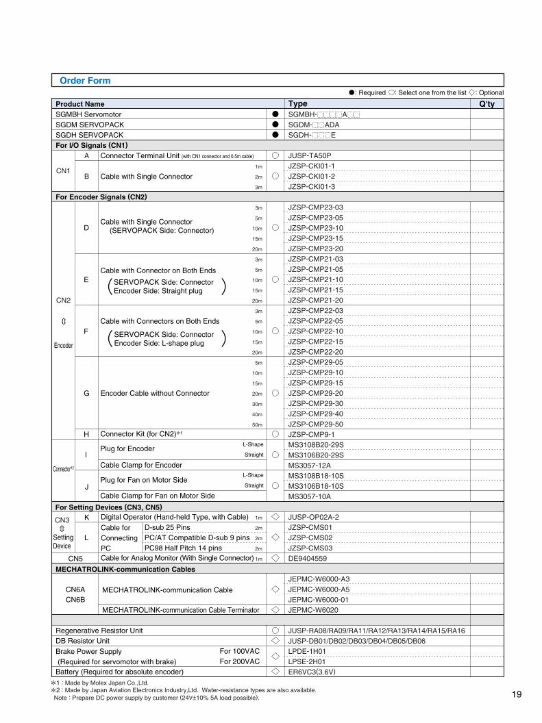
Order Form: Required : Select one from the list : Optional
Q'ty
Connector Terminal Unit (with CN1 connector and 0.5m cable)
Cable with Single Connector
Encoder
D
E
F
G
H
Cable with Single Connector(SERVOPACK Side: Connector)
Cable with Connectors on Both Ends
SERVOPACK Side: ConnectorEncoder Side: L-shape plug
Encoder Cable without Connector
Cable with Connector on Both Ends
SERVOPACK Side: ConnectorEncoder Side: Straight plug
Connector Kit (for CN2)1
Connector2
L-Shape
Straight
L-Shape
Straight
I
J
Plug for Encoder
Cable Clamp for Encoder
Plug for Fan on Motor Side
Cable Clamp for Fan on Motor Side
For Setting Devices (CN3, CN5)
L
KCN3
CN5
SettingDevice
Cable for Analog Monitor (With Single Connector)
Digital Operator (Hand-held Type, with Cable)
Cable forConnectingPC
D-sub 25 PinsPC/AT Compatible D-sub 9 pinsPC98 Half Pitch 14 pins
MECHATROLINK-communication Cables
CN6ACN6B
MECHATROLINK-communication Cable
MECHATROLINK-communication Cable Terminator
For 100VACFor 200VAC
Regenerative Resistor UnitDB Resistor Unit
Battery (Required for absolute encoder)
Brake Power Supply(Required for servomotor with brake)
1 : Made by Molex Japan Co.,Ltd.
2 : Made by Japan Aviation Electronics Industry,Ltd. Water-resistance types are also available.
Note : Prepare DC power supply by customer (24V±10% 5A load possible).
Product NameSGMBH ServomotorSGDM SERVOPACKSGDH SERVOPACKFor I/O Signals (CN1)
For Encoder Signals (CN2)
CN1
CN2
TypeSGMBH- ASGDM- ADA
SGDH- E
JUSP-TA50PJZSP-CKI01-1JZSP-CKI01-2JZSP-CKI01-3
JZSP-CMP23-03JZSP-CMP23-05JZSP-CMP23-10JZSP-CMP23-15JZSP-CMP23-20JZSP-CMP21-03JZSP-CMP21-05JZSP-CMP21-10JZSP-CMP21-15JZSP-CMP21-20JZSP-CMP22-03JZSP-CMP22-05JZSP-CMP22-10JZSP-CMP22-15JZSP-CMP22-20JZSP-CMP29-05JZSP-CMP29-10JZSP-CMP29-15JZSP-CMP29-20JZSP-CMP29-30JZSP-CMP29-40JZSP-CMP29-50JZSP-CMP9-1MS3108B20-29SMS3106B20-29SMS3057-12AMS3108B18-10SMS3106B18-10SMS3057-10A
JUSP-OP02A-2JZSP-CMS01JZSP-CMS02JZSP-CMS03DE9404559
JEPMC-W6000-A3JEPMC-W6000-A5JEPMC-W6000-01JEPMC-W6020
JUSP-RA08/RA09/RA11/RA12/RA13/RA14/RA15/RA16JUSP-DB01/DB02/DB03/DB04/DB05/DB06LPDE-1H01LPSE-2H01ER6VC3(3.6V)
19
LARGE-CAPACITY SERIES
YASKAWA ELECTRIC CORPORATION
IRUMA BUSINESS CENTER (SOLUTION CENTER)480, Kamifujisawa, Iruma, Saitama 358-8555, JapanPhone 81-4-2962-5696 Fax 81-4-2962-6138
YASKAWA ELECTRIC AMERICA, INC.2121 Norman Drive South, Waukegan, IL 60085, U.S.A.Phone 1-847-887-7000 Fax 1-847-887-7370
YASKAWA ELETRICO DO BRASIL COMERCIO LTD.A.Avenida Fagundes Filho, 620 Bairro Saude-Sao Paulo-SP, Brazil CEP: 04304-000Phone 55-11-5071-2552 Fax 55-11-5581-8795
YASKAWA ELECTRIC EUROPE GmbHAm Kronberger Hang 2, 65824 Schwalbach, GermanyPhone 49-6196-569-300 Fax 49-6196-569-312
YASKAWA ELECTRIC UK LTD.1 Hunt Hill Orchardton Woods Cumbernauld, G68 9LF, United KingdomPhone 44-1236-735000 Fax 44-1236-458182
YASKAWA ELECTRIC KOREA CORPORATION7F, Doore Bldg. 24, Yeoido-dong, Youngdungpo-Ku, Seoul 150-877, KoreaPhone 82-2-784-7844 Fax 82-2-784-8495
YASKAWA ELECTRIC (SINGAPORE) PTE. LTD.151 Lorong Chuan, #04-01, New Tech Park 556741, SingaporePhone 65-6282-3003 Fax 65-6289-3003
YASKAWA ELECTRIC (SHANGHAI) CO., LTD.No.18 Xizang Zhong Road. Room 1702-1707, Harbour Ring Plaza Shanghai 200001, ChinaPhone 86-21-5385-2200 Fax 86-21-5385-3299
YASKAWA ELECTRIC (SHANGHAI) CO., LTD. BEIJING OFFICERoom 1011A, Tower W3 Oriental Plaza, No.1 East Chang An Ave.,Dong Cheng District, Beijing 100738, ChinaPhone 86-10-8518-4086 Fax 86-10-8518-4082
YASKAWA ELECTRIC TAIWAN CORPORATION9F, 16, Nanking E. Rd., Sec. 3, Taipei, TaiwanPhone 886-2-2502-5003 Fax 886-2-2505-1280
Printed in Japan January 2006 01-5
LITERATURE NO. KAE-S800-32.3B
05-7⑧
In the event that the end user of this product is to be the military and said product is to be employed in any weapons systems or the manufacture thereof, the export will fall under the relevant regulations as stipulated in the Foreign Exchange and Foreign Trade Regulations. Therefore, be sure to follow all procedures and submit all relevant documentation according to any and all rules, regulations and laws that may apply.
Specifications are subject to change without notice for ongoing product modifications and improvements.
© 2001-2006 YASKAWA ELECTRIC CORPORATION. All rights reserved.Printed on 100% recycled paperwith soybean oil ink.
YASKAWA
3