ac 800m interfacing satt i/o - abb group · ac 800m interfacing satt i/o system version 6.0. ac...
TRANSCRIPT

Power and productivity
for a better worldTM
AC 800MInterfacing SATT I/O
System Version 6.0


AC 800MInterfacing SATT I/O
System Version 6.0

NOTICEThis document contains information about one or more ABB products and may include adescription of or a reference to one or more standards that may be generally relevant tothe ABB products. The presence of any such description of a standard or reference to astandard is not a representation that all of the ABB products referenced in this documentsupport all of the features of the described or referenced standard. In order to determinethe specific features supported by a particular ABB product, the reader should consult theproduct specifications for the particular ABB product.
ABB may have one or more patents or pending patent applications protecting the intel-lectual property in the ABB products described in this document.
The information in this document is subject to change without notice and should not beconstrued as a commitment by ABB. ABB assumes no responsibility for any errors thatmay appear in this document.
In no event shall ABB be liable for direct, indirect, special, incidental or consequentialdamages of any nature or kind arising from the use of this document, nor shall ABB beliable for incidental or consequential damages arising from use of any software or hard-ware described in this document.
This document and parts thereof must not be reproduced or copied without written per-mission from ABB, and the contents thereof must not be imparted to a third party nor usedfor any unauthorized purpose.
The software or hardware described in this document is furnished under a license andmay be used, copied, or disclosed only in accordance with the terms of such license. Thisproduct meets the requirements specified in EMC Directive 2004/108/EEC and in LowVoltage Directive 2006/95/EEC.
TRADEMARKSAll rights to copyrights, registered trademarks, and trademarks reside with their respec-tive owners.
Copyright © 2003-2014 by ABB. All rights reserved.
Release: August 2014Document number: 3BSE042821-600

3BSE042821-600 5
TABLE OF CONTENTS
About This User ManualGeneral ............................................................................................................................17
How to Use This User Manual .............................................................................17
Safety .............................................................................................................18
Important User Information .................................................................................18
European Union Directive Compliance ...............................................................18
UL Listing ............................................................................................................18
CSA Certification.................................................................................................18
Document Conventions ...................................................................................................19
Warning, Caution, Information, and Tip Icons................................................................19
Terminology.....................................................................................................................20
Related Documentation ...................................................................................................21
Section 1 - IntroductionProduct Overview ............................................................................................................23
CI865 ..............................................................................................................................23
CI873 ..............................................................................................................................24
Satt ControlNet ................................................................................................................25
Performance .........................................................................................................26
The ControlNet Cable System .............................................................................27
The ControlNet Components ...............................................................................27
The ControlNet Fiber Components ......................................................................34
Rack I/O...........................................................................................................................38
AC 800M System with Remote Rack-based I/O System.....................................38
Series 200 I/O ..................................................................................................................39
Prerequisites for Connecting to AC 800M ......................................................................41

Table of Contents
6 3BSE042821-600
Rack I/O ............................................................................................................ 41
Series 200 I/O ...................................................................................................... 41
Existing ControlNet Installation .......................................................................... 41
Section 2 - Rebuilding the I/O SystemInstallation Precautions ................................................................................................... 43
Rebuilding Process .......................................................................................................... 45
Rack I/O .......................................................................................................................... 46
Common Rack I/O Components.......................................................................... 46
I/O Addressing ..................................................................................................... 49
Changing to 200-RACN....................................................................................... 50
Installing Rack I/O with 200-RACN ................................................................... 50
Handling the Mains Supply ................................................................................. 51
Handling I/O Signal Connections ........................................................................ 52
Series 200 I/O.................................................................................................................. 55
Section 3 - Connecting AC 800M to the I/O SystemPlanning the Coax Cable System .................................................................................... 58
Determining the Number of Taps ........................................................................ 58
Determining the Type of Cable............................................................................ 59
Determining Trunk Cable Section Lengths ......................................................... 60
Determining the Number of Terminators............................................................. 62
Determining Whether Repeaters are Needed....................................................... 63
Determining the Type of Connectors ................................................................... 64
Application Installation Considerations............................................................... 66
Planning Guidelines ............................................................................................. 69
Planning the Fiber Optic Links ....................................................................................... 70
Cable and Connector Types ................................................................................. 72
Estimating Length of Fiber Cable........................................................................ 74
Planning the Repeaters and the Network Size ................................................................ 75
Network Parameters............................................................................................. 75
Installing the Coax Cable System ................................................................................... 80
Installation of Trunk Cable .................................................................................. 80

Table of Contents
3BSE042821-600 7
3BSE042821-600 7
Mounting the Taps................................................................................................81
Installing Cable Connectors .................................................................................84
Connecting Cable Sections ..................................................................................99
Terminating the Segment .....................................................................................99
Installing Repeaters ............................................................................................100
Connecting Devices............................................................................................106
Installing the Fiber Optic System ..................................................................................107
Fiber Optic Cable ...............................................................................................107
ControlNet Fiber Units.......................................................................................109
Repeater Adapter RPA .......................................................................................112
Fiber Units RPFM and RPFS.............................................................................113
Connecting the Satt I/O Units and CI865......................................................................116
Appendix A - LimitationsControlNet .....................................................................................................................119
Support for Rack I/O .....................................................................................................120
EtherNet/IP Limitations.................................................................................................120
Appendix B - I/O Board Installation and FunctionRack Adapter Board, 200-RACN..................................................................................121
Mounting the Analog-to-digital Converter, ADSF.............................................124
Power Supply Unit, PSF................................................................................................125
Digital Input Boards, IDPG24 and IDPG48..................................................................127
Digital Input Board, IAPG230 ......................................................................................129
Safety Precautions ..............................................................................................130
Digital Output Board, ODPG.8 .....................................................................................131
Relay Output Board, ORG24 ........................................................................................134
Safety Precautions ..............................................................................................136
Digital Output Board, Short-circuit-proof, ODSG ........................................................137
Pulse Counter Board, IPA4............................................................................................140
Reference Voltage ..............................................................................................152
Analog Input Board, IBA ..............................................................................................153
Modules for IBA............................................................................................................160

Table of Contents
8 3BSE042821-600
Installation of MCV200 ..................................................................................... 161
Installation of MCVG ........................................................................................ 162
Installation of the MP, MR and MN Modules ................................................... 162
Analog Output Board, OCAHG.................................................................................... 165
Analog Output Board, OCVA ....................................................................................... 170
Test and Simulation Equipment, PTC and IVAPOT ..................................................... 174
Appendix C - Technical SpecificationsCI865 ........................................................................................................................... 175
ControlNet..................................................................................................................... 177
RPT .......................................................................................................... 177
RPTD .......................................................................................................... 178
RPA .......................................................................................................... 179
RPFM / RPFS ................................................................................................... 180
Mounting Dimensions........................................................................................ 181
I/O Systems - Rack I/O ................................................................................................. 185
General Technical Specifications....................................................................... 185
Rack Adapter Board, 200-RACN ...................................................................... 186
Power Supply Unit, PSF .................................................................................... 187
Digital Input Boards, IDPG24 and IDPG48 ...................................................... 188
Digital Input Boards, IAPG230 ......................................................................... 189
Digital Output Board, ODPG.8.......................................................................... 190
Relay Output Board, ORG24............................................................................. 191
Digital Output Board, Short-circuit-proof, ODSG ............................................ 192
Pulse Counter Board, IPA4 ................................................................................ 193
Analog Input Board, IBA................................................................................... 194
Analog Output Board, OCAHG......................................................................... 199
Analog Output Board, OCVA ............................................................................ 199
I/O Systems - Series 200 I/O......................................................................................... 201
Appendix D - TroubleshootingCI865 ........................................................................................................................... 203
ControlNet..................................................................................................................... 204

Table of Contents
3BSE042821-600 9
3BSE042821-600 9
Coax System.......................................................................................................204
Fibre System.......................................................................................................205
I/O System - Rack I/O ...................................................................................................207
General Instructions ...........................................................................................208
Rack Adapter Board, 200-RACN.......................................................................208
Power Supply Unit, PSF.....................................................................................211
Digital Input Boards, IDPG24 and IDPG48 ......................................................212
Digital Input Board, IAPG230 ...........................................................................212
Digital Output Board, ODPG.8..........................................................................213
Relay Output Board, ORG24 .............................................................................214
Digital Output Board, ODSG.............................................................................214
Pulse Counter Board, IPA4 ................................................................................215
Analog Input Board, IBA ...................................................................................215
Analog Output Board, OCAHG.........................................................................216
Analog Output Board, OCVA ............................................................................216
I/O System - Series 200 I/O...........................................................................................216
Appendix E - ControlNet Cable ComponentsTaps ............................................................................................................................217
Cables ...........................................................................................................................219
Terminators ....................................................................................................................220
Connectors .....................................................................................................................221
Tools ............................................................................................................................222
Adjusting The Cable Strip Tool .........................................................................223
Coax Repeaters .............................................................................................................231
Fiber Repeaters .............................................................................................................231
Appendix F - Rack I/O Parts ListRecommended Components...............................................................................235
Appendix G - Standards
Appendix H - Directive Considerations

Table of Contents
10 3BSE042821-600
INDEX

3BSE042821-600 11
Safety Summary
Electrostatic Sensitive DeviceDevices labeled with this symbol require special handling precautions as described in the installation section.
GENERAL WARNINGS
Equipment EnvironmentAll components, whether in transportation, operation or storage, must be in a noncorrosive environment.
Electrical Shock Hazard During MaintenanceDisconnect power or take precautions to insure that contact with ener-gized parts is avoided when servicing.
SPECIFICWARNINGS
Page 85: The cable strip tool is delivered with the proper blade cutting depth already set and there is no need to adjust it.
Page 107: Do not look directly into the fiber ports. Light levels may cause damage to eyesight.
Page 111: Do not insert or remove units with power connected to the attached repeater adapter.
Page 121: Because of the risk of electrostatic discharge, we recommend that you wear an ESD bracelet when handling the I/O boards.
Page 126: Switch off the mains supply voltage power before any opera-tion with the PSF unit.
Page 130: For safety reasons, and in order to meet the Low Voltage Directive, the precautions in this subsection must be taken in the applica-tion.
Page 136: For safety reasons, and in order to meet the Low Voltage Directive, the precautions in this subsection must be taken in the applica-tion.

12 3BSE042821-600
SPECIFICWARNINGS
cont.
Page 207: Read the section Safety Summary, before performing opera-tions which can be dangerous for personnel or cause damage to equip-ment.
Page 241: Note that the units are “Open type equipment” and must be mounted in suitable cabinets.
Page 241: Note also that external power supplies used to provide 24 V DC must be CE-marked.
Page 228: The blades should be on top as you slide the cartridge.

3BSE042821-600 13
SPECIFIC CAUTIONS
Page 43: Backup the existing application before disconnecting the old system.
Page 58: Proper selection of ControlNet cable, connectors, accessories, and installation techniques is necessary to make sure it is not accidentally grounded.
Page 59: Taps must be purchased from ABB for the network to function properly. The drop cable must not be extended or shortened.
Page 60: When interconnecting equipment in different buildings, use fiber optic cables to obtain galvanic isolation.
Page 60: When determining the cable length of trunk cable sections, make sure you measure the actual cable path as it is routed on your net-work.
Page 62: The use of high-flex cable should be kept to a minimum.
Page 63: Note the restrictions of the network size in subsection “Planning the Repeaters and the Network Size of a ControlNet”.
Page 65: Do not let any metallic surfaces on the BNC connectors, plugs, or optional accessories touch grounded metallic surfaces. All connectors for ControlNet must be of type 75 ohm.
Page 70: Fiber optic links are mandatory to avoid lightning problems when interconnected equipment is placed in different buildings.
Page 76: Do not change the Network Parameters while the factory pro-cess is running

14 3BSE042821-600
SPECIFIC CAUTIONS
cont.
Page 80: You should have read the section “Planning the Coax Cable System of the ControlNet” before you install your cable system.
Page 82: Do not allow any metal portions of the tap, such as the universal mounting bracket screws or connectors, to contact any conductive mate-rial.
Page 82: Use only the screws supplied with the tap. They are of proper length and head style.
Page 90: Check for any braid stranding that may not have been cut at the proper length. Even one strand coming in contact with the center conduc-tor could short out the cable.
Page 91: Replace the trunk cable section if problems persist with the cable after completing these tests.
Page 92: Make sure that the center pin slips onto the center conductor completely. The back shoulder of the center pin should be up against the white insulation.
Page 94: Note that the center pin, when installed in the connector, must be sufficiently pushed forward. If the visible part of the center pin is too short then a reliable connection can not be guaranteed.
Page 95: All cables ends must have tight-fitting connectors. Pull the con-nector to verify that it is attached.
Page 98: It is necessary to disconnect all devices from the drop cables before the cable segment is tested.
Page 103: Do not allow any metal portions of the tap to contact any con-ductive material. This may cause noise on the network.
Page 107: Observe the minimum cable bend radius specified. Do not touch the ends of the fiber optic strands and do not let the ends come in contact with dust, dirt or other contaminants.

3BSE042821-600 15
SPECIFIC CAUTIONS
cont.
Page 110: The adapter and repeater units must be secured with DIN rail anchors. Failure to do so may result in the loss of communications and/or cause damage to the units.
Page 111: If you exceed the unit or power limit, you may cause damage to the repeater adapter and units.
Page 112: Make sure all fiber units are attached and secured prior to applying power to the adapter.
Page 114: Never connect the fiber cable between channel 1 and 2 on the same RPFM, or between channels on different RPFMs attached to the same RPA.
Page 144: Both clear inputs on the Pulse Counter Board, IPA4, must be activated to reset a 16-bit counter.
Page 146: Do not reset the counters on the Pulse Counter Board, IPA4, when counting!
Page 157: The signal cables for the Analog Input Board, IBA must be shielded twisted pair and grounded at both ends.
Page 174: The boards PTC and IVAPOT do not meet the EMC directive 89/336/EEC.
Page 225: The first and second blade adjustments need to be very pre-cise.

16 3BSE042821-600

3BSE042821-600 17
About This User Manual
GeneralThis manual describes how to take advantage of re-using old Satt I/O units (Rack I/O, Series 200 I/O, and I/O 200C) and how to install the new hardware needed on the field level, preparing for the installation of the new controller AC 800M. Please refer to the AC 800M Controller Hardware (3BSE036351*) manual regarding installation of the AC 800M controller and the CI865. Refer to the AC 800M EtherNet/IP DeviceNet Configuration (9ARD000014*) manual for the CI873 configuration.
How to Use This User Manual
Section 1, Introduction: Provides an overview of the hardware needed to rebuild the I/O system.
Section 2, Rebuilding the I/O System: Description of how to prepare the I/O systems for communication via Satt ControlNet. Read this section if there is no Satt ControlNet connected to the I/O system.
Section 3, Connecting AC 800M to the I/O System: A guide to the planning and installation of the ControlNet. It also provides information about how to connect the CI865 unit and the I/O systems to the ControlNet.
Appendix A, Limitations - Appendix H, Directive Considerations
• List of the limitations of the Satt ControlNet and the I/O systems.
• Description the I/O boards and units suitable for the Rack I/O system.
• Technical data about the parts of the ControlNet and Rack I/O systems.
• Description of the troubleshooting procedure of the ControlNet and Rack I/O systems.

Safety About This User Manual
18 3BSE042821-600
• Standards and lists of cable components.
Safety
Because of the variety of uses for the products described in this publication, those responsible for the application and use of this control equipment must satisfy themselves that all necessary steps have been taken to assure that each application and use meets all performance and safety requirements, including any applicable laws, regulations, codes and standards.
Important User Information
The illustrations, charts, sample programs and layout examples shown in this manual are intended solely for purposes of example. Since there are many variables and requirements associated with any particular installation, ABB Automation does not assume responsibility or liability (to include intellectual property liability) for actual use based upon the examples shown in this publication.
European Union Directive Compliance
Units mentioned in this document for which product is marked with the logo comply with the electromagnetic compatibility directive 89/336/EEC and the low-voltage directive 73/23/EEC, see Appendix H, Directive Considerations.
UL Listing
Units mentioned in this document are UL listed if product is marked with the
UL logo. indicates UL approval for the USA, and for Canada
as well. The logo indicates UL approval for Canada only.
The applied standard is UL508, Industrial Control Equipment. Units approved for use in hazardous locations also comply with the standard UL1604.
CSA Certification
Units mentioned in this document are CSA certified if product is marked with
the logo. The applied standard is C22.2, No. 142-M1987.

About This User Manual Document Conventions
3BSE042821-600 19
Units approved for use in hazardous locations also comply with the standard C22.2, No. 213-M1987. To fulfill the CSA requirements for hazardous locations, the instructions in Appendix G, Standards must be followed.
Document ConventionsMicrosoft Windows conventions are normally used for the standard presentation of material when entering text, key sequences, prompts, messages, menu items, screen elements, etc.
Warning, Caution, Information, and Tip IconsThis publication includes Warning, Caution, and Information where appropriate to point out safety related or other important information. It also includes Tip to point out useful hints to the reader. The corresponding symbols should be interpreted as follows:
Although Warning hazards are related to personal injury, and Caution hazards are associated with equipment or property damage, it should be understood that operation of damaged equipment could, under certain operational conditions, result
Electrical warning icon indicates the presence of a hazard which could result in electrical shock.
Warning icon indicates the presence of a hazard which could result in personal injury.
Caution icon indicates important information or warning related to the concept discussed in the text. It might indicate the presence of a hazard which could result in corruption of software or damage to equipment/property.
Information icon alerts the reader to pertinent facts and conditions.
Tip icon indicates advice on, for example, how to design your project or how to use a certain function

Terminology About This User Manual
20 3BSE042821-600
in degraded process performance leading to personal injury or death. Therefore, fully comply with all Warning and Caution notices.
TerminologyA complete and comprehensive list of Terms is included in the IndustrialIT Extended Automation System 800xA, Engineering Concepts instruction (3BDS100972Rxxxx). The listing included in Engineering Concepts includes terms and definitions that apply to the 800xA system where the usage is different from commonly accepted industry standard definitions and definitions given in standard dictionaries such as Webster’s Dictionary of Computer Terms.
Term/Acronym Description
200-ACN ControlNet Adapter for Series 200 I/O.
200-RACN Rack Adapter ControlNet.
200-AENTR EtherNet/IP Adapter for Series 200 I/O.
CI865 AC 800M communication interface for Satt ControlNet
CI873 AC 800M Communication interface for EtherNet/IP.
Coax repeater A two port active component that reconstructs and retransmits all traffic it receives on one segment side to another segment side.
ControlNet ControlNet is a high-performance network for industrial applications. ControlNet is a registered trademark from Allen-Bradley, Inc. (http://www.allen-bradley.com).
DDC Direct Digital Control.
Fiber optic link Links two or more coax segments together.
Fiber unit RPFM or RPFS
Connects a fiber repeater adapter to other fiber units via two fiber channels.
Fiber repeater adapter RPA
Connects up to 4 fiber units to a trunk cable tap.

About This User Manual Related Documentation
3BSE042821-600 21
Related Documentation
A complete list of all documents applicable to the 800xA IndustrialIT Extended Automation System is provided in Released User Documents, 3BUA000263Rxxxx. This document lists applicable Release Notes and User Instructions. It is provided in PDF format and is included on the Release Notes/Documentation media provided with your system. Released User Documents are updated with each release and a new file is provided that contains all user documents applicable for that release with their applicable document number. Whenever a reference to a specific instruction is made, the instruction number is included in the reference.
Network A collection of nodes – with unique addresses in the range of 01–99.
Node Any physical device connected to the ControlNet cable system which requires a network address in order to function on the network – a network may contain a maximum of 32 nodes. Examples of nodes are CI865, 200-ACN and 200-RACN.
PIOS35 A Rack with space for 16 I/O boards.
PSF Power Supply Unit used in PIOS35.
PTU2 A cable with two ready-wired edge connectors at one end and screw terminal blocks at the other end. Suitable for rack I/O boards.
Segment Trunk cable section connected via taps with terminators at each end, and with no repeaters included.
Tap The connection between any device and the ControlNet coax cable system.
Terminator A 75 ohm resistor mounted in a BNC plug.
Trunk cable The bus or central part of a cable system.
Trunk cable section The length of a cable between any two taps.
Term/Acronym Description

Related Documentation About This User Manual
22 3BSE042821-600
3BSE042821-600 23
Section 1 Introduction
Product OverviewThis section gives an overview of the hardware needed on the field level to control the Satt I/O units with an AC 800M controller. The Satt I/O system consists of Rack I/O and Series 200 I/O family (S200 I/O, S200L I/O and I/O 200C).
There is a list at the end of this chapter (see Prerequisites for Connecting to AC 800M on page 41) containing the essential parts needed for rebuilding of Satt I/O.
Series 200 I/O connectivity can be established through ControlNet and through EtherNet/IP using 200-AENTR EtherNet/IP adapter. Rack I/O connectivity can be established through ControlNet only.
CI865The CI865 unit is the AC 800M communication interface for Satt ControlNet. The CI865 unit makes it possible to use older Satt I/O system (Rack I/O and Series 200 I/O) with the AC 800M controller platform. The unit handles I/O scanning of up to 31 distributed I/O nodes. CI865 supports online replacement (Hot Swap), and does not require any configuration before installation.
The CI865 is mounted on a DIN rail and connects to the CEX bus via a shielded DB25P connector towards the master side and a shielded DB25S connector towards the expansion side. In the front of the unit there is a BNC-type connector to connect the ControlNet cable, see Figure 1. The base plate has a code lock that prevents installation of an incorrect type of unit onto it.The CI865 expansion unit contains the CEX-Bus logic, ControlNet bus logic, CPU and a DC/DC converter that supplies appropriate voltages from the +24 V supply, via the CEX-Bus. Please refer to the manual AC 800M Controller Hardware, Hardware and Operation (3BSE036351*) for more information about the CI865.

CI873 Section 1 Introduction
24 3BSE042821-600
Figure 1. The CI865 unit from different angles.
CI873The 200-AENTR device interfaces with the AC 800M controller, through the CI873 communication interface module. CI873 acts as an EtherNet/IP I/O scanner class device. It originates connections to EtherNet/IP enabled devices and exchanges real time I/O data with them.
For more information refer to the AC 800M EtherNet/IP DeviceNet Configuration (9ARD000014*) manual
Section 1 Introduction Satt ControlNet
3BSE042821-600 25
Satt ControlNetSatt ControlNet is a fieldbus for industrial applications which provides transport of application information. The connected devices are handled as I/O in the controller.
Two types of information will be transferred over the network:
• Control and I/O data
• Non-time critical data (client/server messaging) such as configuration.
Please observe that the Satt ControlNet described in this manual is only applicable for communication between Satt I/O systems and AC 800M.

Performance Section 1 Introduction
26 3BSE042821-600
Performance
• Bit rate: 5 Mbit/s.
• 32 nodes per network (including the controller)1.
– Up to 31 200-ACN nodes, or
– up to eight 200-RACN nodes, or
– a mix of 200-ACN and 200-RACN containing together a maximum of 3968 binary I/O channels or equivalent, see Figure 2.
• Up to 48 taps in a 250 m coax segment.
• RG6 coaxial cable (75 ohm) and BNC connectors - simple to install.
• Up to 1 km network length without repeaters.
• Fiber optic links may be included to increase network length and obtain galvanic isolation. The total attenuation of a fiber cable section must be less than 13.3 dB, implying section lengths up to about 7000 m.
• 62.5/125 mm multi mode optic fiber is used with ST connectors, operating at 1300 nm wavelength.
Figure 2. One network can handle up to 32 nodes.
1. Each node must be designated a unique address between 01 and 99. Node number 01 is always reserved for the CI865. See also the manual AC 800M Controller Hardware, Hardware and Operation.
Sat
t Con
trol
Net
CI8
65
200-RACN
200-ACN
1 node
31 nodes
A maximum of eight 200-RACN nodes can be connected to the CI865
32 nodes
AC 800M

Section 1 Introduction The ControlNet Cable System
3BSE042821-600 27
The ControlNet Cable System
The ControlNet cable system gives a flexibility while designing a communication network for your particular application. To take full advantage of this flexibility, you should spend sufficient time planning how to install your cable system before assembling any of the hardware, see Section 3, Connecting AC 800M to the I/O System.
Use Figure 3 to understand the ControlNet cable system:
Figure 3. ControlNet network
The ControlNet Components
The ControlNet cable system comprises the following components:
• nodes,
• taps1,
• trunk cable1,
1. For information on purchasing these components, see Appendix E, ControlNet Cable Components.
1. Coax segment2. Trunk cable section3. Tap4. Nodes CI865, 200-ACN or 200-RACN5. Coax repeater RPT or RPTD6. Fiber optic link7. Fiber optic cable8. Fiber repeater adapter RPA9. Fiber unit RPFM or RPFS
4
5
6
8
9
7
2
1
3

The ControlNet Components Section 1 Introduction
28 3BSE042821-600
• cable connectors1,
• terminators1,
• segments,
• repeaters1,
• networks.
Nodes
Nodes are defined as physical devices connecting to the ControlNet cable system that require a network address in order to function on the network.
Figure 4. Example of a node is the ControlNet adapter 200-ACN. Refer to the S200 I/O, Hardware and Installation, User’s Guide (3BSE021356Rxxxx) for information about 200-ACN.

Section 1 Introduction The ControlNet Components
3BSE042821-600 29
Taps
Taps connect each node on a network to the cable system via an integral one meter drop cable.
There are four different taps available:
Figure 5. Tap connections via drop cable.
Figure 6. Taps with T or Y placement of BNC connectors.
Drop cable (1 m)
T-Tap
Y-Tap

The ControlNet Components Section 1 Introduction
30 3BSE042821-600
Also see the section Determining the Number of Taps on page 58.
Trunk Cable
The trunk cable is the bus, or central part of the ControlNet cable system. The trunk cable is composed of multiple sections of cable. See Appendix E, ControlNet Cable Components for ordering cables.
There are several types of cables you can use depending on the environment in which you are installing your cable system. See section Determining the Type of Cable on page 59.
Cable Connectors
A cable connector attaches trunk cable sections to the tap. The tap is connected through a BNC connector.
Figure 7. Taps with a straight or right angle connector on the drop cable.
Figure 8. Cable Connectors
Right angleStraight

Section 1 Introduction The ControlNet Components
3BSE042821-600 31
Optional Connectors
ABB also offers optional cable connectors for use in your network configuration. See the section Determining the Type of Connectors on page 64, for available connectors.
Terminators
A 75-ohm terminator must be installed on the tap at each end of a segment.
Segments
A segment is a collection of trunk cable sections and taps, delimited by two terminators.
The allowed total length of a segment is depending on the number of taps in your segment. See the section Determining Trunk Cable Section Lengths on page 60 for detailed information.
Network
Figure 9. Terminators
Figure 10. Segments

The ControlNet Components Section 1 Introduction
32 3BSE042821-600
A network is a collection of nodes forming:• a segment,• multiple segments connected together via repeaters.
Each node in a network must have a unique address in the range of 1-991. In the example in the figure below, two segments are linked by a coax repeater to form a node network.
1. Note that the communication interface unit CI865 limits the number of nodes in a network. Node number 1 is reserved to CI865. For more information, please refer to the manual AC 800M Controller Hardware, Hardware and Operation (3BSE036351Rxxxx)
Figure 11. Network

Section 1 Introduction The ControlNet Components
3BSE042821-600 33
Coax Repeater
For error conditions see Troubleshooting the Repeaters on page 204.
A repeater is used to increase the number of nodes, extend the total length of your segment or create a star or tree configuration (goes off in multiple directions from one point). Use a repeater in your ControlNet cable system to connect segments together to form networks. The number of repeaters is limited depending on your network topology.
Figure 12. Coax Repeater
Table 1. Coax Repeater, Indicators
Indication Function
Flashing red/green The repeater is being powered-up or reset. The LEDs alternately flash red and green for about 5 s.
Steady green Normal operation mode.
1
2
3
Front panel1 = Status indicators2 = Reset switch3 = Replaceable fuse

The ControlNet Fiber Components Section 1 Introduction
34 3BSE042821-600
When you insert a repeater into your cable system, you create a new segment. The same restrictions on the number of taps and cable length apply to this new segment as segments without repeaters.
The repeater provides:
• An internal power supply,
• a fuse (replaceable) for over-current protection,
• two indicators for status and trouble-shooting,
• a relay contact indicating fault.
The ControlNet Fiber Components
A fiber optic link connects two or more coax segments together and comprises the following components:
• fiber repeater adapter,
• fiber module,
• fiber optic cable.
Fiber optic links must be used to interconnect equipment in different buildings, in order to obtain galvanic isolation and to avoid problems with lightning and electrical interference. They can also increase the total network length. The fiber repeater
Figure 13. Segments Connected with a Repeater
Segment 1
Repeater
Segment 2
Section 1 Introduction The ControlNet Fiber Components
3BSE042821-600 35
adapter connects up to 4 fiber modules to a coax segment by means of a drop cable and tap.
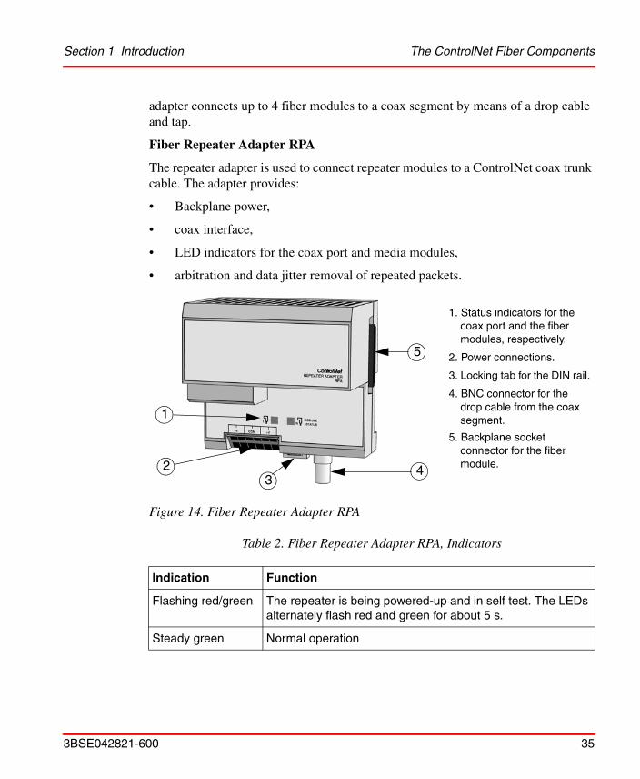
Fiber Repeater Adapter RPA
The repeater adapter is used to connect repeater modules to a ControlNet coax trunk cable. The adapter provides:
• Backplane power,
• coax interface,
• LED indicators for the coax port and media modules,
• arbitration and data jitter removal of repeated packets.
Figure 14. Fiber Repeater Adapter RPA
Table 2. Fiber Repeater Adapter RPA, Indicators
Indication Function
Flashing red/green The repeater is being powered-up and in self test. The LEDs alternately flash red and green for about 5 s.
Steady green Normal operation
1
42
5
3
1. Status indicators for the coax port and the fiber modules, respectively.
2. Power connections.
3. Locking tab for the DIN rail.
4. BNC connector for the drop cable from the coax segment.
5. Backplane socket connector for the fiber module.

The ControlNet Fiber Components Section 1 Introduction
36 3BSE042821-600
For error conditions see Troubleshooting the Fiber Repeater Adapter on page 205.
Fiber Module RPFM and RPFS
The module provides:
• two fiber channels,
• activity LED indicators for each fiber channel.
The indicators are steady green during normal operation with data activity. For error conditions see Troubleshooting the Fiber Module on page 207.
Fiber Optic Cable
Use fiber optic cable to connect fiber modules at a great distance from each other, housed in different buildings or separated by hazardous or electrically noisy areas.
There are different types of cable for use in different environments, see also Cable and Connector Types on page 72 and Fiber Optic Cable on page 107. 62.5/125 m multi mode fiber is used with ST connectors (plastic or ceramic), operating at 1300 nm wavelength.
Note that a faulty fiber channel can be masked by several good fiber channels, if the repeater has more than one fiber module connected.
Figure 15. Fiber Module RPFM and RPFS
3
6 7
1 4 2
5
1. Channel 1 fiber port.
2. Channel 2 fiber port.
3. Protective cap.
4. Locking tab for the DIN rail.
5. Status indicators for channel 1 and 2, respectively.
6. Left-side backplane plug con-nector for the fiber repeater adapter or another fiber mod-ule.
7. Right-side backplane socket connector for another fiber module.

Section 1 Introduction The ControlNet Fiber Components
3BSE042821-600 37
Network ConfigurationA functionality similar to that of a coax repeater (see Planning the Repeaters and the Network Size on page 75) is achieved by means of two fiber repeater adapters and two fiber modules:
A new coax segment is added to the network, with the normal restrictions on cable length and number of taps.
Figure 16. Fiber Optic Cable
Figure 17. Network Configuration
2
3 4
1
1. Coax segment 1.
2. Coax segment 2.
3. Fiber repeater adapter RPA.
4. Fiber module RPFM or RPFS.

Rack I/O Section 1 Introduction
38 3BSE042821-600
Rack I/OThe rack-based I/O system consists of a 19-inch central rack intended for double sized Euro-boards. The rack-based I/O system is intended for industrial use and meets the EMC directive 89/336/EEC and the Low-Voltage Directive, LVD, 73/23/EEG with supplement 93/68/EEG.
AC 800M System with Remote Rack-based I/O System
To use the AC 800M controller for a rack-based I/O system a 200-RACN unit (Rack Adapter ControlNet) needs to be mounted in the rack. The 200-RACN unit is a re-mote ControlNet I/O adapter for rack-based I/O boards. See Rack Adapter Board, 200-RACN on page 121 for more information about the 200-RACN unit.
The rack that is suited for 200-RACN is called PIOS35. The PIOS35 rack has space for 16 I/O boards, see Figure 18. The I/O boards are connected to the rack via two different connectors (X1 and X2), see Figure 19. The upper connector (X1) is used for connection of the input/output signals of the process and the lower connector (X2) is used to connect the rack’s internal bus and power supply.
Each rack contains a power supply unit, PSF, located on the outermost right side of the rack. The rack can be supplied via the mains or 24 V DC. Filters and mains connections are located at the rear of the rack. See Power Supply Unit, PSF on page 125 for more information about the PSF.
Figure 18. Rack-based I/O system connection alternative.
Remote rack
CI865AC 800M controller
200-RACN
Satt ControlNet
PSF

Section 1 Introduction Series 200 I/O
3BSE042821-600 39
Figure 19. X1 and X2 connectors.
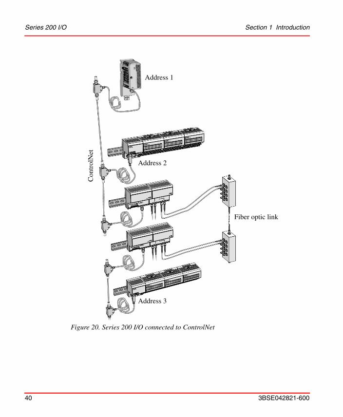
Series 200 I/OThe Series 200 I/O is a flexible, modular I/O system for central and distributed applications. The Series 200 I/O units are mounted on a DIN rail and have to be connected to a 200-ACN unit to be able to communicate via Satt ControlNet. The 200-ACN is a remote I/O adapter unit, intended for connection of terminal base units equipped with I/O units. Also connected to Satt ControlNet is the CI865, making it possible to use the AC 800M controller to control the Series 200 I/O units, see Figure 20. S200 I/O modules can also be connected to 200-AENTR to communicate through EtherNet/IP.
For more information about the Series 200 I/O, please refer to any of the manuals S200 I/O Hardware (3BSE021356*), S200L and I/O 200C I/O Hardware (3BSE021357*), I/O 200C Installation and Maintenance (493104811).
X1
X2
Series 200 I/O Section 1 Introduction
40 3BSE042821-600
Figure 20. Series 200 I/O connected to ControlNet
Fiber optic link
Con
trol
Net
Address 1
Address 2
Address 3

Section 1 Introduction Prerequisites for Connecting to AC 800M
3BSE042821-600 41
Prerequisites for Connecting to AC 800M
Rack I/O
If the existing system is based on Rack I/O the following equipment is needed to rebuild the system:
• The rack has to be a PIOS35 rack.
• A 200-RACN unit (+ maybe an ADSF attached to the 200-RACN, see Mounting the Analog-to-digital Converter, ADSF on page 124), to be mounted in every rack.
• A CI865 unit.
• A ControlNet cable system, which is to be connected between the 200-RACN in the rack and the CI865.
Series 200 I/O
If the existing system is based on Series 200 I/O the following equipment are needed to rebuild the system using ControlNet.
• A 200-ACN unit, to be connected to every Series 200 I/O node.
• A CI865 unit.
• A ControlNet cable system, which is to be connected between the 200-ACN unit and the CI865.
The following equipment are needed to rebuild the system using EtherNet/IP.
• A 200-AENTR unit, to be connected to every Series 200 I/O node.
• A CI873 unit.
Existing ControlNet Installation
If there is an existing Satt ControlNet installed between the I/O units and legacy controller (such as SattCon 200 and Advant Controller 250), just move the coax cable from the old controller system to the new CI865 unit. In that case it is no need to rebuild anything on the field level.

Existing ControlNet Installation Section 1 Introduction
42 3BSE042821-600

3BSE042821-600 43
Section 2 Rebuilding the I/O System
This section describes how to rebuild an existing Satt I/O system (Rack I/O or Series 200 I/O and I/O 200C) making it possible to connect to the Satt ControlNet. Please read Installation Precautions below before you continue to the rebuilding part.
For the rebuilding of:
• Rack I/O see page 46 and Rebuilding Process on page 45.
• Series 200 I/O see page 55 and Rebuilding Process on page 45.
Installation PrecautionsA system installed according to the instructions in this document will meet the ABB Automation environmental specifications for industrial equipment. These specifications are concerned with electrical environment, climate and mechanical tests.
It is strongly recommended to backup the existing application before disconnecting the old system.

Installation Precautions Section 2 Rebuilding the I/O System
44 3BSE042821-600
Figure 21. A system installed according to the instructions in this document will meet the ABB environmental specifications for industrial equipment.
With the proper precautions, the system can operate safely and reliably in normal industrial environments. These precautions can be minimized, if the following locations are avoided:
• Where the ambient temperature is outside the range +5 to +55°C,
• where the relative humidity exceeds 90%,
• where condensation may occur following sudden temperature changes,
• where high-power electrical interference may occur,
• where corrosive or inflammable gases exist,
• where there is dust, conductive particles, oil mist or organic solutions present,
• where high electrostatic or magnetic fields exist,
• where the equipment is exposed to direct sunlight,
• where vibrations and mechanical shocks may be transmitted to the equipment,
• where the equipment can be exposed to water,
• close to powerful high- frequency sources (possible problems can be solved with external filters).
Climate tests
Electrical environment tests
Mechanical tests

Section 2 Rebuilding the I/O System Rebuilding Process
3BSE042821-600 45
Rebuilding Process
Figure 22. Graphic representation of the rebuilding process.

Rack I/O Section 2 Rebuilding the I/O System
46 3BSE042821-600
Rack I/OThe following text deals with rebuilding Rack I/O so it can be connected to the Satt ControlNet. When connected to the Satt ControlNet the I/O boards can connect to the CI865 and the AC 800M controller.
This subsection starts with listing some common components for Rack I/O supported by the Satt ControlNet. It also contains information about how to handle the mains supply and the I/O signal connections.
This subsection describes two cases before rebuilding the Rack I/O system:
• The existing rack is a PIOS35 rack. Changing to 200-RACN on page 50 describes the different alternatives to connect a 200-RACN unit to the rack.
• The rack is not a PIOS35 rack. The whole rack needs to be replaced as described in Installing Rack I/O with 200-RACN on page 50.
Common Rack I/O Components
See the Appendix F, Rack I/O Parts List for a complete list of supported components.
Table 3. Important Components for Rack I/O Supported by the Satt ControlNet
Order code Name/Function
200-RACN Rack adapter board for remote rack-based I/O connected to a AC 800M system.
200-RACN/A Rack adapter board, 200-RACN with analog to digital converter, ADSF, mounted.
ADSF Central A/D converter. To be mounted on rack adapter board 200-RANN.
Modules to IBA 12 accessory modules for analog input board IBA.
PIOS35 Empty basic rack.
PSF Power supply unit.
PTU2 Two ready-wired I/O connectors with cables and screw terminal blocks mounted on an aluminium profile.

Section 2 Rebuilding the I/O System Common Rack I/O Components
3BSE042821-600 47
Table 4. Combined Products
Order code Name/Function
PIOS/RC Basic rack, PIOS35, with power supply, PSF, and 200-RACN
PIOS/RCA Basic rack, PIOS35, with power supply, PSF and 200-RACN/A
Table 5. Supported I/O Boards
Board code Name/Function
IAPG Digital input board with 16 inputs
IDLD Digital input board with 16 inputs
IDP Digital input board with 32 inputs
IDPG Digital input board with 32 inputs
IDN Digital input board with 32 inputs
IDI Digital input board with 32 inputs
PTC Digital input board with 32 inputs
ORG Digital output board with 16 outputs
ORGH Digital output board with 16 outputs
OATG Digital output board with 16 outputs
ODP2 Digital output board with 16 outputs
ODPG2 Digital output board with 16 outputs
ORM Digital output board with 16 outputs
ODP.5 Digital output board with 32 outputs
ODP.8 Digital output board with 32 outputs
ODPG.8 Digital output board with 32 outputs
ODPL.5 Digital output board with 32 outputs

Common Rack I/O Components Section 2 Rebuilding the I/O System
48 3BSE042821-600
ODPLD Digital output board with 32 outputs
ODN.2 Digital output board with 32 outputs
ODLD.5 Digital output board with 32 outputs
ODSG Digital output board with 32 optocoupled outputs, short circuit proof
IBA Analog input board with 8 inputs
IRA Analog input board with 8 inputs
ICA Analog input board with 8 inputs
IVA Analog input board with 8 inputs
IVAPOT Analog input board with 8 inputs
OCVA Analog output board with 2 outputs
OCAHG Analog output board with 4 outputs
OCAH Analog output board with 4 outputs
OCAH with hand station
Analog output board with 4 outputs
IPA4 Input pulse analyzer board with 4 inputs, 8 bit counters
Table 5. Supported I/O Boards (Continued)
Board code Name/Function

Section 2 Rebuilding the I/O System I/O Addressing
3BSE042821-600 49
I/O Addressing
Every input/output signal is assigned a unique I/O address. This address is used when the I/O board is called by the control system. Above each board position in the racks there is a number (octal). The address number is obtained by adding the number of the board position to the number of the input/output on the board.
Figure 23. I/O addressing
A digital input/output board can have a maximum of 32 inputs/outputs. These are numbered from 0 to 37 (octal). The board positions are accordingly numbered in steps of 40 (octal). All board positions which end in 00 are marked with black numbers and those which end in 40 are marked with red numbers to simplify reading the addresses. The same color coding is used on the front panel of the I/O board.
The analog output signals consist of eight or twelve bits. This means that an analog output board has two or four outputs. The address of an analog output signal must therefore be a multiple of 10 (octal). Each rack can have a maximum of 512 (777 octal) input/output signals.
Analog input addresses are always a multiple of 4 (octal), as an analog input board contains eight inputs (channels 00 - 04 - 10 - 14 - 20 - 24 - 30 - 34).

Changing to 200-RACN Section 2 Rebuilding the I/O System
50 3BSE042821-600
Changing to 200-RACN
If the existing rack is a PIOS35 rack there are three solutions to rebuild the rack depending on present conditions.
If the existing PIOS35 rack is equipped with:
• A CPU:
– Disconnect the CPU and connect a 200-RACN unit.
• A 200-RANN unit:
– Disconnect the 200-RANN unit and connect a 200-RACN unit.
• A PBAD unit or PBX unit:
– Disconnect the PBAD or PBX unit and connect a 200-RACN unit.
For more information about the 200-RACN unit, see Appendix B, I/O Board Installation and Function.
Installing Rack I/O with 200-RACN
If the existing rack is not a PIOS35 rack, the rack needs to be replaced with a PIOS35 rack with 200-RACN. To install a PIOS35 rack with the existing I/O boards, follow this procedure:
1. Disconnect all X1 contacts from the new PIOS35 rack, they are not needed anymore.
2. Mark up each old X1 contact and I/O board carefully to keep track of which X1 contact that belongs to which I/O board. Remove the I/O boards from the rack.
3. Disconnect all X1 contacts from the existing rack, by removing the two screws. Do not remove or change the signal wires on the X1 contact!
4. Read Handling the Mains Supply on page 51 and Handling I/O Signal Connections on page 52. Then remove the old rack and replace it with a new PIOS35 rack.
5. Connect the old X1 contacts to the new PIOS35 rack.

Section 2 Rebuilding the I/O System Handling the Mains Supply
3BSE042821-600 51
6. Connect all old I/O boards to the new PIOS35 rack. Be careful about the position, so that every I/O board is connected to the same X1 contact as it was in the old rack.
Handling the Mains Supply
Each rack must have a mains power supply. The power supply unit, PSF, located on the right side of the rack, requires a mains supply voltage 230 or 110 V AC, or 24 V DC. Select the correct mains supply voltage, see "Mains Supply Selection for PSF", on page 126. It can be seen from Figure 24 how the power supply is connected to the rack.
Figure 24. The mains supply connection.
Figure Explanation
The connection of the AC supply cable is shown Figure 24. The lower connector X2 is used when a 24 V DC supply is connected.
• Part A: Terminal for incoming AC mains supply (PE) = protective earth, 0 (N) = neutral and ~(L) = line voltage. Power supply, PSF, has mains supply settings for 110 V and 230 V, and can also be powered by 24 V DC.
• Part B: X1:1 (+VR) and X1:2 (0V) are the incoming DC supply lines for I/O boards using relays, mounted in the central rack. X1:2 is internally connected to the chassis. It can not be disconnected.
C
B
A
Mains filter
Common earthing point
See below for an explanation of the parts A,B and C.
Handling I/O Signal Connections Section 2 Rebuilding the I/O System
52 3BSE042821-600
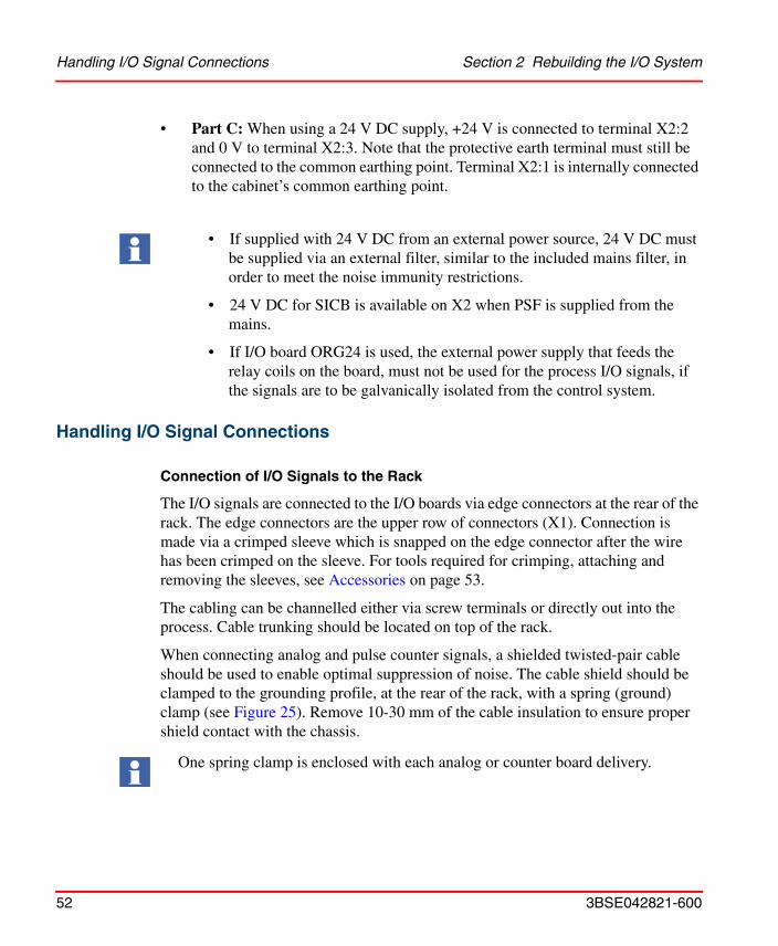
• Part C: When using a 24 V DC supply, +24 V is connected to terminal X2:2 and 0 V to terminal X2:3. Note that the protective earth terminal must still be connected to the common earthing point. Terminal X2:1 is internally connected to the cabinet’s common earthing point.
Handling I/O Signal Connections
Connection of I/O Signals to the Rack
The I/O signals are connected to the I/O boards via edge connectors at the rear of the rack. The edge connectors are the upper row of connectors (X1). Connection is made via a crimped sleeve which is snapped on the edge connector after the wire has been crimped on the sleeve. For tools required for crimping, attaching and removing the sleeves, see Accessories on page 53.
The cabling can be channelled either via screw terminals or directly out into the process. Cable trunking should be located on top of the rack.
When connecting analog and pulse counter signals, a shielded twisted-pair cable should be used to enable optimal suppression of noise. The cable shield should be clamped to the grounding profile, at the rear of the rack, with a spring (ground) clamp (see Figure 25). Remove 10-30 mm of the cable insulation to ensure proper shield contact with the chassis.
• If supplied with 24 V DC from an external power source, 24 V DC must be supplied via an external filter, similar to the included mains filter, in order to meet the noise immunity restrictions.
• 24 V DC for SICB is available on X2 when PSF is supplied from the mains.
• If I/O board ORG24 is used, the external power supply that feeds the relay coils on the board, must not be used for the process I/O signals, if the signals are to be galvanically isolated from the control system.
One spring clamp is enclosed with each analog or counter board delivery.

Section 2 Rebuilding the I/O System Handling I/O Signal Connections
3BSE042821-600 53
Figure 25. A shielded cable where the shield is grounded with a spring clamp. Crimp sleeves are crimped to the three wires of the cable.
Accessories
CRT01 and CRT02 are crimp tools and CRIMP1 and CRIMP2 are crimp sleeves for I/O signal connections to the rack. CRT01 and CRIMP1 are used for 0.14-0.5 mm2 cables. CRT02 and CRIMP2 are used for 0.75-1.5 mm2 cables. CRRE is a crimp removal tool.
Figure 26. Crimp tools
CRT01 or CRT02
CRRE

Handling I/O Signal Connections Section 2 Rebuilding the I/O System
54 3BSE042821-600
Ready-wired Connectors for I/O Boards, PTU2
A PTU2 kit comprising a cable with two ready-wired edge connectors at one end and screw terminal blocks at the other end (see Figure 27), can be ordered from ABB Automation. This kit can be used for most digital I/O boards but if there is any doubt, contact ABB Automation before ordering. The amount of installation work can be considerably reduced using PTU2.
A PTU2 kit contains two ready-wired connectors for two board positions and a connection block with screw terminals for the signal leads, see Figure 27.
Figure 27. PTU2 kit.
• The PTU2 kit is only for digital boards.
• The “b” column of the connector X1 (power supply voltage and 0 V) must be adapted to each board type.

Section 2 Rebuilding the I/O System Series 200 I/O
3BSE042821-600 55
Series 200 I/OTo connect the Series 200 I/O system to the CI865, associated with the AC 800M controller, the Series 200 I/O needs to communicate via Satt ControlNet. If the set up has 200-ANN or 200-AIO units, then it is preferable to replace these with 200-AENTR and use EtherNet/IP instead. If the S200 I/Os are connected using 200-ACN, then they do not need to be replaced with 200-AENTR.
How to remove and mount these adapters is described in the chapter Mounting Instructions in the manual S200 I/O Hardware, Hardware and Installation (3BSE021356*).
In addition to the replacement, the 200-ACN / 200-AENTR unit also needs a power source to be installed. This is also described in the manual S200 I/O Hardware, Hardware and Installation, chapter General Installation Instructions. Note that the 200-ACN / 200-AENTR and the I/O system should, if possible, have separate 24 V DC supplies.
If the old system is based on any of the controllers SattCon, Sattline or AC 250, replace the controller with a AC 800M controller.
If the old system contains Advant Controller 210, AC 800C or 200-AIO units, replace each of them with a 200-AENTR unit. It is also possible by replacing each of them with 200-ACN, but most preferable is with 200-AENTR.

Series 200 I/O Section 2 Rebuilding the I/O System
56 3BSE042821-600

3BSE042821-600 57
Section 3 Connecting AC 800M to theI/O System
The ControlNet is based on a coax cable system. However, in some cases parts of the system also needs optic fibre links. As described later in this section fiber optic links may be included in a ControlNet system to increase network length and to obtain galvanic isolation in a highly noisy environment. Its use is mandatory to avoid lightning problems when interconnected equipment is placed in different buildings.
This section contains the following parts:
• Planning the ControlNet
– Planning the Coax Cable System on page 58.
– Planning the Fiber Optic Links on page 70.
– Planning the Repeaters and the Network Size on page 75.
• Installing the ControlNet
– Installing the Coax Cable System on page 80.
– Installing the Fiber Optic System on page 107.
• Connect the nodes to the ControlNet
– Connecting the Satt I/O Units and CI865 on page 116.

Planning the Coax Cable System Section 3 Connecting AC 800M to the I/O System
58 3BSE042821-600
Planning the Coax Cable SystemUse this section to determine your network requirements. After reading this section, consult engineering drawings of your facility for specific information concerning the best location for installing your cable network.
Determining the Number of Taps
The number of taps needed, depends on the number of devices you want to connect to the network. You will need a tap for each node and repeater on a segment.
If you plan to add nodes at a later date, you should consider ordering and installing the cable and connectors for these additional nodes when you install the initial cable system. This will minimize disruption to the network during operation. If you are planning future installation of additional nodes, do not install the tap. Instead, install a BNC bullet connector (see “Determining the Type of Connectors” on page 64 for more information). Figure 28 shows the contents of each tap kit:
The ControlNet cable system is a ground isolated coaxial network. Proper selections of cable, connectors, accessories, and installation techniques are necessary to make sure it is not accidentally grounded.
The maximum number of nodes on the entire Satt ControlNet is restricted to 32, including the CI865 unit. However, since a repeater is not a node but needs a tap, the maximum number of taps can be higher than the number of nodes.
Figure 28. Tap kit
Dust cap
Drop cable (1 m)
For noise suppression, ferrite beads are molded on the drop cable.
BNC connector kit
Universal mounting bracket
Screws
Section 3 Connecting AC 800M to the I/O System Determining the Type of Cable
3BSE042821-600 59
Determining the Type of Cable
There are a number of cable types available to meet different requirements:
• Standard RG6 cable for normal indoor industrial applications, –40° to +80°C.
• Flooded burial, moisture resistant for outdoor applications, –55° to +80°C.
• Plenum-FEP, fire resistant for high- and low-temperature applications, as well as corrosive areas (harsh chemicals), –70° to +200°C.
• High-Flex RG-6 cable for mobile device applications, –40° to +75°C.
• Messenger cable for aerial runs where a great tensile strength is required, –40° to +80°C.
• Standard cable armored PVC/aluminum or PVC/steel for heavy duty applications, –40° to +80°C.
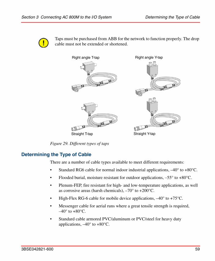
Taps must be purchased from ABB for the network to function properly. The drop cable must not be extended or shortened.
Figure 29. Different types of taps
Right angle T-tap Right angle Y-tap
Straight T-tap Straight Y-tap

Determining Trunk Cable Section Lengths Section 3 Connecting AC 800M to the I/O System
60 3BSE042821-600
• Siamese, dual standard cable, –40° to +80°C.
Only use cable types listed in Appendix E, ControlNet Cable Components. Note that different manufacturers may specify somewhat different temperature limits.
Observe the local country regulation codes for installation work.
Keep high-flex cable use to a minimum because it reduces the allowed cable section length. Connect the high-flex cable by means of BNC bullet connectors (BNCJ) to make it easy to replace it before its flexure life is exceeded.
Determining Trunk Cable Section Lengths
A segment is consisting of several sections of trunk cables, separated by taps. The total cable length of a segment is equal to the sum of all the trunk cable sections.
Total trunk cable length or number of taps may be increased by installing repeaters on the segment. This creates another segment.
Select the shortest path for routing the cable to minimize the amount of cable you need. The specific details of planning such a cable route depends upon the demands of your network.
When interconnecting equipment in different buildings, use fiber optic cables to obtain galvanic isolation, see Section “Planning the Fiber Optic Links” on page 70.
When determining the cable length of trunk cable sections, make sure you measure the actual cable path as it is routed on your network. Consider vertical dimensions as well as horizontal dimensions. The three dimensional routing path distance should always be calculated when determining cable lengths.
Figure 30. Determining trunk cable section lengths
Terminator
Tap
Trunk cable section

Section 3 Connecting AC 800M to the I/O System Determining Trunk Cable Section Lengths
3BSE042821-600 61
RG-6 Cable except High-Flex
The maximum allowed length of the cable system depends on the number of taps connected. There is no minimum trunk cable section length requirement. The maximum allowed total length of a segment is 1000 m with two taps connected. Each additional tap decreases the maximum length of the segment by 16.3 m. The maximum number of taps allowed on a segment is 48 with a maximum length of 250 m.
Maximum allowed segment length is:
1000 m – 16.3 m × (number of taps – 2)
High-Flex RG-6
High-flex cables are used where a connected device is movable, for example a jib. In such cases both standard and high-flex cables are used.
The total allowed length of a segment depends on the number of taps connected and the length of high-flex RG-6 cable.
The maximum allowed total length of a high-flex cable segment is 625 m with two taps connected. Each additional tap decreases the maximum length of the segment. The maximum number of taps allowed on a segment is 48.
Maximum allowed segment length for standard RG-6 in a mixed configuration with high-flex/standard cables is:
Figure 31. Number of taps
Number of taps
Maximum allowed segment length =1000 m – 16.3 m x (number of taps –2)
Cable length

Determining the Number of Terminators Section 3 Connecting AC 800M to the I/O System
62 3BSE042821-600
(1000 m - (L × 1.61)) – ((16.3 m × (number of taps – 2)) where L=total length of high-flex cable sections in the network segment.
Both Standard and High-Flex Cables in the Same Segment
Example:
• The segment has three nodes (requires three taps).
• The segment requires 200 m of high-flex RG-6 cable.
To calculate the maximum cable length of standard RG-6 cable:
1000 m – 200 m × 1.6 – 16.3 m × (3–2) = 663.7 m.
Determining the Number of Terminators
75 ohm terminators must be used at both ends of each segment for the ControlNet cable system to work.
1. This calculation (length x 1.6) makes the necessary length adjustment for high-flex RG-6 cable.
The amount of high-flex RG-6 cable possible to use in a system, is less than the amount of standard RG-6 cable, and the use of high-flex cable should be kept to a minimum. Use BNC bullet connectors to isolate areas that require high-flex RG-6 cable from areas that require standard RG-6 cable. This allows the high-flexRG-6 section to be replaced before flexure life is exceeded.
Figure 32. Terminator
After determining how many segments there will be on the network, multiply this number by two to figure out how many terminators are necessary for the network.

Section 3 Connecting AC 800M to the I/O System Determining Whether Repeaters are Needed
3BSE042821-600 63
Determining Whether Repeaters are Needed
Installing repeaters is necessary if the system requires more than 48 taps per segment, or a longer trunk cable than the specifications allow.
Figure 33. Determining whether repeaters are needed
Note the restrictions in Section “Planning the Repeaters and the Network Size” on page 75.
If each segment is less than 250 m, each segment may contain up to 48 taps, including the repeaters linking to other segments. The sum of nodes in all of the segments is maximum 32.
RepeaterSegment 1
Segment 2
Number of taps
Cable length Repeater required
Repeater not required
Maximum number of nodes

Determining the Type of Connectors Section 3 Connecting AC 800M to the I/O System
64 3BSE042821-600
Configuring Network with Repeaters
When you configure your network using repeaters, the following applies:
• Only one path is allowed between two nodes.
• Max. 32 nodes are allowed on the network (Each node must be designated a unique address between 01 and 99, where the node address 01 is reserved for the CI865.).
• The propagation delay limits the combination of cable length and the number of repeaters in series between two arbitrary nodes, see Section “Planning the Repeaters and the Network Size” on page 75.
For segment lengths, see “Determining Trunk Cable Section Lengths” on page 60. See also the examples of installing coax repeaters on page 104 and fiber repeaters on page 114.
Determining the Type of Connectors
These connectors are available:
A repeater can be connected to a segment at any tap location.
Table 6. Determining the Type of Connectors
BNC connector: Function
cable connector connects trunk cable sections to a tap’s BNC connector
Optional BNC connector: Function
bullet (jack-to-jack) reserves a space in the trunk cable for future installation of a tap or to splice a trunk cable
barrel (plug-to-plug) connects two adjacent taps without a trunk cable section between them

Section 3 Connecting AC 800M to the I/O System Determining the Type of Connectors
3BSE042821-600 65
In the example below, the ControlNet cable:
• Enters and exits the panel enclosure from the side using isolated bulkhead connectors,
• contains two adjacent taps connected by a barrel connector,
• reserves one future tap location with a bullet connector,
• makes a sharp bend with a right angle connector.
isolated bulkhead (jack-to-jack)
goes through grounded panel walls while maintaining the shield isolation of the trunk cable
right angle (jack-to-plug)
provides a 90° bend in your cable (prevents excessive bending of your cable)
Do not let any metallic surfaces on the BNC connectors, plugs, or optional accessories touch grounded metallic surfaces. All connectors for ControlNet must be of type 75.
Table 6. Determining the Type of Connectors (Continued)
BNC connector: Function

Application Installation Considerations Section 3 Connecting AC 800M to the I/O System
66 3BSE042821-600
Application Installation Considerations
When planning your cable system there are certain installation considerations depending on your application. There are three categories of conductors:
Figure 34. Example of how to use different connectors.
Table 7. The three categories of conductors.
Category Includes
III
• AC power lines
• high-power digital AC I/O lines
• high-power digital DC I/O lines
• power cables to motors
1
3
6
2
54
1. Panel wall
2. Barrel connector (BNCP)
3. Bullet connector (BNCJ)
4. Right angle connector (BNCRJP)
5. Taps
6. Isolated bulkhead connector (BNCJI)
Cable enters and exits from the side

Section 3 Connecting AC 800M to the I/O System Application Installation Considerations
3BSE042821-600 67
General Wiring Guidelines
Follow these guidelines for wiring all ControlNet cables:
• If the cable must cross power feed lines, it should do so at right angles.
• Route at least 1.5 m from high voltage enclosures, or sources of RF/microwave radiation.
• If the conductor is in a metal wireway or conduit, each section of that wireway or conduit must be connected to each adjacent section so that it has electrical conduction along its entire length. The metal wireway or conduit must also be bonded to the enclosure at the entry point.
Wiring External to Enclosures
Cables that run outside protective enclosures are relatively long. To minimize cross-talk from nearby cables, it is good practice to maintain maximum separation between the ControlNet cable and other potential noise conductors. The cable should be routed according to the guidelines in Table 8.
II• low-power digital AC/DC I/O lines
• ControlNet communication cables
I
• analog I/O lines and DC power lines for analog circuits
• low-voltage DC power lines
• communication cables to connect between system components within the same enclosure
Table 7. The three categories of conductors. (Continued)
Category Includes

Application Installation Considerations Section 3 Connecting AC 800M to the I/O System
68 3BSE042821-600
Wiring Inside Enclosures
Cable sections that run inside protective equipment enclosures are relatively short. As with wiring external to enclosures, you should maintain maximum separation between your ControlNet cable and Category-III conductors.
Inside an enclosure, route Control Net Cables outside cable trunks, or in a cable trunk separated from Category-III conductors.
Table 8. Wiring External to Enclosures
Cable in a contiguous metallic wireway or conduit?
Route your cable at least:
From noise sources of this strength:
0.08 m Category-III conductors of less than 20 A
Yes 0.15 m AC power lines of 20 A or more, up to 100 kVA
0.3 m AC power lines greater than 100 kVA
0.15 m Category-III conductors of less than 20 A
No 0.3 m AC power lines of 20 A or more, up to 100 kVA
0.6 m AC power lines greater than 100 kVA
Table 9. Wiring Inside Enclosures
Route your cable at least this distance:
From noise sources of this strength:
0.08 m Category III conductors of less than 20 A
0.15 m AC power lines of 20A or more, up to 100 kVA
0.6 m AC power lines greater than 100 kVA

Section 3 Connecting AC 800M to the I/O System Planning Guidelines
3BSE042821-600 69
Surge Suppression
Transient electromagnetic interference (emi) can be generated whenever inductive loads such as relays, solenoids, motor starters, or motors are operated by “hard contacts” such as push button or selector switches. These wiring guidelines assume you guard your system against the effects of transient emi by using surge-suppressors to suppress transient emi at its source. Inductive loads switched by solid state output devices alone, do not require surge suppression. However, inductive loads of AC output units that are in series or parallel with hard contacts, require surge-suppression to protect the unit output circuits as well as to suppress transient emi.
Planning Guidelines
Now that you are ready to begin ordering components, use these guidelines to help you select components.
General Planning
The ControlNet cable system is isolated from earth and must be protected from inadvertent ground connections.
For repeaters, observe the temperature and humidity specifications in Appendix C, Technical Specifications. Also avoid high electrostatic and electromagnetic fields, corrosive and inflammable gases, dust, conductive particles, oil mist and organic solutions. The repeaters must not be exposed to water or to direct sunlight. See also the installation instructions on page 103.
Segment Planning
• All connections to the trunk cable require a tap.
• Taps may be installed at any location on the trunk cable.
• Tap drop cable length must not be changed.
• The CI865 can be connected to the trunk cable anywhere in the segment, not only at the ends. The node number does not need to follow the physical placement of the unit.
• Maximum number of taps = 48, with max. 250 m of trunk cable.

Planning the Fiber Optic Links Section 3 Connecting AC 800M to the I/O System
70 3BSE042821-600
• Maximum trunk cable length = 1000 m, with 2 taps.
• 75 ohm terminators are required on both ends.
• Unconnected drop cables are not allowed with one exception; one tap with an unconnected drop cable may be installed for maintenance purposes.
• Use BNC bullet connectors at future tap locations.
• Avoid high noise environments when routing cables.
Network Planning
• Max. 32 nodes are allowed on the network (each node must be designated a unique address between 01 and 99).
• Repeaters require a tap, but are not counted as nodes.
• Repeaters may be installed at any tap location along a segment.
• Only one path is permitted between any two nodes on a network.
• Maximum propagation delay between two arbitrary nodes must not be exceeded, see Section “Planning the Repeaters and the Network Size” on page 75.
For segment lengths, see page 60, and the installation examples on pages 104 and 105.
Planning the Fiber Optic Links
Point-to-point, multidrop and star configurations are created by use of standard fiber cable, fiber repeater adapters and fiber units. The fiber repeater adapter (RPA) is
If you are installing a bullet connector for future tap installations, count the bullet as one of the tap allotments on your segment (and decrease the maximum allowed cable length by 16 m). This helps you avoid reconfigure your network when you install the tap.
Fiber optic links may be included in a ControlNet system to increase network length and to obtain galvanic isolation in a highly noisy environment. Its use is mandatory to avoid lightning problems when interconnected equipment is placed in different buildings.
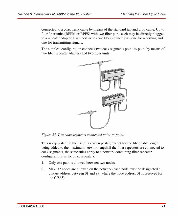
Section 3 Connecting AC 800M to the I/O System Planning the Fiber Optic Links
3BSE042821-600 71
connected to a coax trunk cable by means of the standard tap and drop cable. Up to four fiber units (RPFM or RPFS) with two fiber ports each may be directly plugged to a repeater adapter. Each port needs two fiber connections, one for receiving and one for transmitting signals.
The simplest configuration connects two coax segments point-to-point by means of two fiber repeater adapters and two fiber units:
This is equivalent to the use of a coax repeater, except for the fiber cable length being added to the maximum network length.If the fiber repeaters are connected to coax segments, the same rules apply to a network containing fiber repeater configurations as for coax repeaters:
1. Only one path is allowed between two nodes.
2. Max. 32 nodes are allowed on the network (each node must be designated a unique address between 01 and 99, where the node address 01 is reserved for the CI865).
Figure 35. Two coax segments connected point-to-point.

Cable and Connector Types Section 3 Connecting AC 800M to the I/O System
72 3BSE042821-600
3. The propagation delay limits the combination of cable length and the number of repeaters in series between two arbitrary nodes, see Planning the Repeaters and the Network Size on page 75.
See also the example of installing fiber repeaters on page 114.
It is not necessary to connect fiber repeaters to coax segments if they are used only to increase the fiber cable length. It is possible to connect two coax segments by a chain of fiber repeaters as shown below:
If the total cable length (coax + fiber) is 10 km and if there are 5 fiber repeater adapters, the actual propagation delay is 59 s according to Table 11. If the network update time NUT=5 ms, then you must choose the highest node address Smax 17 to be found by interpolation in Table 12 or by use of the formula on page 79.
Cable and Connector Types
The fiber units RPFM and RPFS are designed for use with 62.5/125 m multi mode optic fiber and plastic or ceramic connectors type ST. The wavelength used is 1300 nm.
Multi-fiber cables for backbone use are available with a wide range of fiber counts, e.g. 4, 16, 72, or 216 fibers. They should contain a suitable amount of spare fibers and should be installed between connector panels, to which the local equipment is connected by means of shorter, flexible one- or two-fiber interconnect cables, see Figure 37 and Figure 38.
Figure 36. Connection of two coax segments by a chain of fiber repeaters.
RPARPFM
or RPFS
200-RACN
Coax segment
200-RACN CI865
Coax segmentFiber optic cable
RPARPFM
or RPFS
RPARPFM
or RPFS
RPARPFM
or RPFS
RPARPFM
or RPFS

Section 3 Connecting AC 800M to the I/O System Cable and Connector Types
3BSE042821-600 73
There is a big choice of fiber optic cables designed for use in different environments, e.g. indoor or outdoor industrial applications, high-temperature applications, aerial runs, or direct burial.
Fiber optic cables should be installed by specially trained personnel, capable of taking full responsibility. Consult the specialists what cable type should be used for the specific application.
Figure 37. Multi-fiber backbone cable (1) and two-fiber interconnect cable (2).
Figure 38. Connector panel with incoming multi-fiber backbone cable (1) and connectors for interconnect cables (2).
1
2
1
2
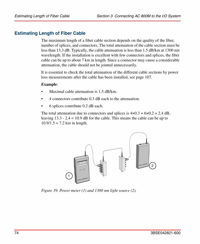
Estimating Length of Fiber Cable Section 3 Connecting AC 800M to the I/O System
74 3BSE042821-600
Estimating Length of Fiber Cable
The maximum length of a fiber cable section depends on the quality of the fiber, number of splices, and connectors. The total attenuation of the cable section must be less than 13.3 dB. Typically, the cable attenuation is less than 1.5 dB/km at 1300 nm wavelength. If the installation is excellent with few connectors and splices, the fiber cable can be up to about 7 km in length. Since a connector may cause a considerable attenuation, the cable should not be jointed unnecessarily.
It is essential to check the total attenuation of the different cable sections by power loss measurements after the cable has been installed, see page 107.
Example:
• Maximal cable attenuation is 1.5 dB/km.
• 4 connectors contribute 0.3 dB each to the attenuation.
• 6 splices contribute 0.2 dB each.
The total attenuation due to connectors and splices is 4×0.3 + 6×0.2 = 2.4 dB, leaving 13.3 - 2.4 = 10.9 dB for the cable. This means the cable can be up to 10.9/1.5 = 7.2 km in length.
Figure 39. Power meter (1) and 1300 nm light source (2).
1
2

Section 3 Connecting AC 800M to the I/O System Planning the Repeaters and the Network Size
3BSE042821-600 75
Planning the Repeaters and the Network SizeThere are restrictions on network size with respect to:
• The length of coax and fiber cable sections,
• the number of coax and fiber repeaters,
• the number of coax cable taps,
• the number of addressable nodes,
• the desired network update time (NUT).
The first three restrictions are due to the physical attenuation of signals in the cable and are independent of software and the control system used. Refer to the sections “Determining Trunk Cable Section Lengths” on page 60 and “Estimating Length of Fiber Cable” on page 74 for coax and fiber cables respectively. See also the examples of installing coax repeaters on page 104 and fiber repeaters on page 114.
The control system can handle a maximum of 32 nodes. Each node must be designated a unique address between 01 and 99, where the node address 01 is reserved for the CI865. Please refer to the manual AC 800M Controller Hardware, Hardware and Operation (3BSE036351Rxxxx) for more information.
The last two restrictions depend on a number of parameters which may be specified in the controller hardware configuration. How to calculate those parameters is described below.
Network Parameters
The physical configuration and topology determines the propagation delay of the network. The propagation delay is the time needed for a signal to travel between the two end nodes of the network, furthest from each other. The propagation delay also determines possible network update times, and the highest node address. Therefore, the network has to be carefully planned in order to be able to use short update times, and many nodes in the network.
The settings listed in Table 10 affect the performance of the Satt ControlNet network. When changing any of the first four parameters in Table 10 all connections are disconnected and are then reconnected after up to 25 seconds.

Network Parameters Section 3 Connecting AC 800M to the I/O System
76 3BSE042821-600
To change these settings, double-click the CI865 icon in the Control Builder, see Figure 40, and choose the Settings tab in the Editor. Refer to the Control Builder online help for further information.
Do not change these settings when the factory process is running.
Table 10. Available network parameters
Parameter Description
Network Update Time (NUT)
Sets the desired update time of Satt ControlNet in ms. The lowest setting for this parameter is dependent on the network parameters Highest Node Address (Smax), cable length and number of repeaters. If the value of this parameter is too low, a compiler error message is displayed during compilation. Try a higher value or change some of the other parameters. Nodes can be assigned update times that are multiples of this setting, see Default Expected Packet Rate below. The EPR cannot be assigned values smaller than the Network Update Time.
Highest Node Address (Smax)
The highest addressable node on the network. Nodes with addresses higher than this cannot be connected. If this setting is lower than the highest defined node, a compiler error message is displayed during compilation. To optimize the network it is recommended that you keep this setting as low as possible by setting the addresses in consecutive order starting with the number 2.
Cable length The maximum cable length on the network. Calculate the total cable length between all combinations of end points in the network. Set the parameter to the maximum of these values.

Section 3 Connecting AC 800M to the I/O System Network Parameters
3BSE042821-600 77
Figure 40. Example of hardware connected to the Satt ControlNet.
# Repeaters Number of repeaters on the longest segment of the network. Set this parameter to the actual number of repeaters between the two end points that generated the value for cable length above.
Default Expected Packet Rate (EPR)
Default update time for nodes that do not specify an Expected Packet Rate of their own. Changing this parameter causes all nodes that use default Expected Packet Rate to be reconnected. Can only have values which are multiples of the Network Update Time. If this value causes the bandwidth to become full, a compiler error message is displayed during compilation.
Table 10. Available network parameters (Continued)
Parameter Description
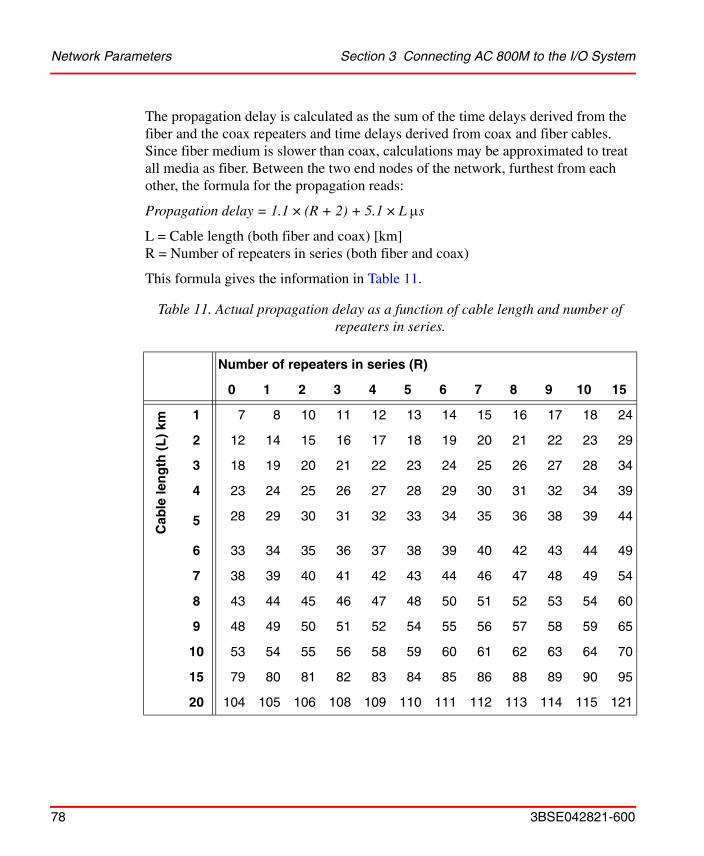
Network Parameters Section 3 Connecting AC 800M to the I/O System
78 3BSE042821-600
The propagation delay is calculated as the sum of the time delays derived from the fiber and the coax repeaters and time delays derived from coax and fiber cables. Since fiber medium is slower than coax, calculations may be approximated to treat all media as fiber. Between the two end nodes of the network, furthest from each other, the formula for the propagation reads:
Propagation delay = 1.1 × (R + 2) + 5.1 × L s
L = Cable length (both fiber and coax) [km]R = Number of repeaters in series (both fiber and coax)
This formula gives the information in Table 11.
Table 11. Actual propagation delay as a function of cable length and number of repeaters in series.
Number of repeaters in series (R)
0 1 2 3 4 5 6 7 8 9 10 15
Cab
le le
ng
th (
L)
km
1 7 8 10 11 12 13 14 15 16 17 18 24
2 12 14 15 16 17 18 19 20 21 22 23 29
3 18 19 20 21 22 23 24 25 26 27 28 34
4 23 24 25 26 27 28 29 30 31 32 34 39
5 28 29 30 31 32 33 34 35 36 38 39 44
6 33 34 35 36 37 38 39 40 42 43 44 49
7 38 39 40 41 42 43 44 46 47 48 49 54
8 43 44 45 46 47 48 50 51 52 53 54 60
9 48 49 50 51 52 54 55 56 57 58 59 65
10 53 54 55 56 58 59 60 61 62 63 64 70
15 79 80 81 82 83 84 85 86 88 89 90 95
20 104 105 106 108 109 110 111 112 113 114 115 121

Section 3 Connecting AC 800M to the I/O System Network Parameters
3BSE042821-600 79
When the actual propagation delay of the network has been calculated, it is possible to choose the network update time and the highest node address. It is done with the formula for the maximum allowed propagation delay as a function of network update time and the highest node address:
Max allowed propagation delay = 225 × (NUT / Smax) - 6.4 s
NUT = Network update time [ms] Smax = Highest node address
This formula gives the information in Table 12. Also, due to physical limitations, the propagation delay is limited to:
Max allowed propagation delay = 121 s
The actual propagation delay from Table 11 must be smaller than the maximum value from Table 12.
Table 12. Maximum allowed propagation delay as a function of NUT and SMAX.
Highest node address (Smax)
2 5 10 15 20 25 30 40 50 60 70 80 90
Net
wo
rk u
pd
ate
tim
e (N
UT
) m
s 5 121 121 106 69 50 39 31 22 16 12 10 8 6
10 121 121 121 121 106 84 69 50 39 31 26 22 19
15 121 121 121 121 121 255 218 163 130 107 42 36 31
20 121 121 121 121 121 121 121 224 179 148 58 50 44
30 121 121 121 121 121 121 121 121 121 230 90 78 69
40 121 121 121 121 121 121 121 121 121 121 121 106 94
50121 121 121 121 121 121 121 121 121 121 121 121 119

Installing the Coax Cable System Section 3 Connecting AC 800M to the I/O System
80 3BSE042821-600
Example: The longest segment in the network has a cable length of 2 km, and a total of 4 repeaters in series. This will give a propagation delay of 17 s from Table 11. If the user wants the highest node address to be 25, Table 12 indicates that the network update times can be 5 ms and more.
The above mentioned network configuration parameters are later needed by the user to configure his network in the hardware configuration tool. The user has to know the actual cable length (L), the number of repeaters (R) and possible values for NUT and Smax.
Note: Even if the tables above indicate that the network will work with some values of NUT and Smax, there is no guarantee that the bandwidth will be sufficient. Especially if the user uses a short network update time and wants to send a lot of data on the network. The tables are only tools to help checking if the physical network is possible to configure.
See also the examples of installing coax repeaters on page 104 and fiber repeaters on page 72 and 114.
How to set the required parameters is described in the manuals for the different controller systems.
Installing the Coax Cable System
Installation of Trunk Cable
Install the trunk cable, observing the cable supplier’s installation instructions and the following guidelines.
You should have read the Section “Planning the Coax Cable System” on page 58 before you install your cable system.

Section 3 Connecting AC 800M to the I/O System Mounting the Taps
3BSE042821-600 81
Wiring External To Enclosures
When the RG-6 type coax cable is being pulled through multiple conduit bends, follow these specifications.
Wiring Inside Enclosures
When the RG-6 type coax cable is not being pulled through conduit, follow these specifications (they may vary slightly from different manufacturers).
Mounting the Taps
Selecting Where to Mount the Taps
• There is no spacing requirement between taps. It is possible to install two adjacent taps by using a barrel connector.
• Make sure the mounting location is convenient for the cable routing.
Table 13. Installation of Trunk Cable, Wiring External To Enclosures.
For this coax cable:The pulling force should not exceed:
Bending radius should not be less than:
PVC 42 kg 76 mm
FEP 61 kg 70 mm
High-Flex Not available Not available
Table 14. Installation of Trunk Cable, Wiring Inside Enclosures.
For this coax cable: The bending radius should not be less than:
PVC 38 mm
FEP 35 mm
High-Flex Not available
Tap drop cable 25 mm

Mounting the Taps Section 3 Connecting AC 800M to the I/O System
82 3BSE042821-600
• Make sure the mounting location does not cause any bending radius to be less than the limits listed on page 81.
• Do not mount the tap in a position that routes the drop cable over any AC power terminals on nearby units.
The ControlNet taps (Y-tap and T-tap) can be mounted:
• To a universal mounting bracket, and then the tap and bracket are mounted as an assembly.
• Through the body holes in the tap using:– Screws and flat washers.– A tie wrap.
See “Mounting Dimensions” on page 181 in Appendix , Technical Specifications for universal mounting bracket and tap mounting dimensions.
Mounting a Tap Using a Universal Mounting Bracket
1. Align the universal mounting bracket with the mounting holes on the tap.
2. Using the screws provided with the tap, attach the tap to the universal mounting bracket, see Figure 41.
Do not allow any metal portions of the tap, such as the universal mounting bracket screws or connectors, to contact any conductive material.
Use only the screws supplied with the tap. They are of proper length and head style.
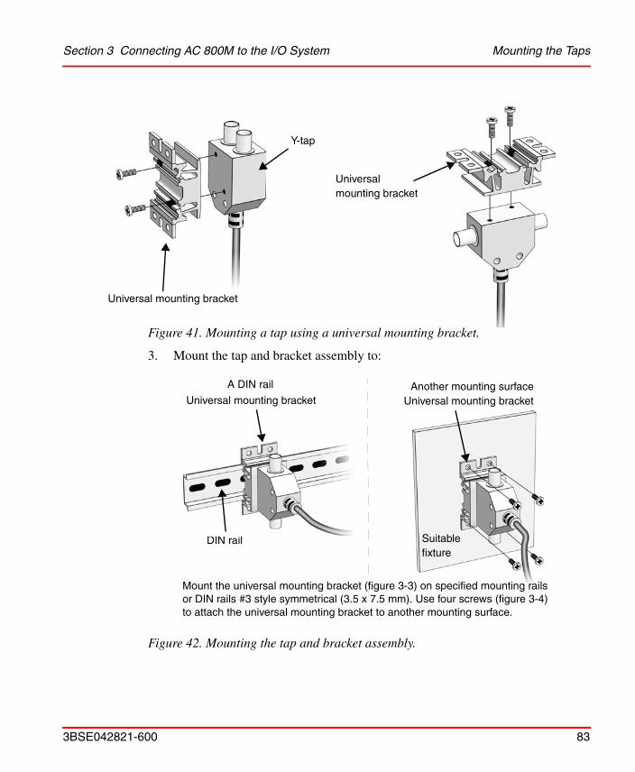
Section 3 Connecting AC 800M to the I/O System Mounting the Taps
3BSE042821-600 83
Figure 41. Mounting a tap using a universal mounting bracket.
3. Mount the tap and bracket assembly to:
Figure 42. Mounting the tap and bracket assembly.
Y-tap
Universal mounting bracket
Universal mounting bracket
DIN rail Suitable fixture
A DIN rail
Universal mounting bracketAnother mounting surface
Universal mounting bracket
Mount the universal mounting bracket (figure 3-3) on specified mounting rails or DIN rails #3 style symmetrical (3.5 x 7.5 mm). Use four screws (figure 3-4) to attach the universal mounting bracket to another mounting surface.

Installing Cable Connectors Section 3 Connecting AC 800M to the I/O System
84 3BSE042821-600
Figure 43. Mounting a tap through the body holes.
Installing Cable Connectors
After mounting of the taps, the cable connectors should be attached to the ends of the trunk cable sections.
Collecting Tools
To install the cable connectors, use the tools in the ControlNet Tool Kit, see Figure 44 and Appendix E, ControlNet Cable Components.
Figure 44. ControlNet Tool Kit Complete
Body holes
Tie wrap
Flat washers
Screws
Tie wrap
Cable strip tool with two blade cassettes (one for PVC and one for FEP)
Terminators and extra connectors
Memory blade cartridge (contains two sets of blades)Memory blade
holder
Strip gauge
Crimp tool
Wire cutter
Knife

Section 3 Connecting AC 800M to the I/O System Installing Cable Connectors
3BSE042821-600 85
Stripping the Cable
When cutting cable sections, make them long enough to route from one tap to the next with sufficient slack so that the bending radius is not less than:
• 76 mm for wiring external to enclosures,
• 38 mm for wiring inside enclosures.
When stripping the cable proceed as follows:
1. Verify that the strip tool is set correctly for the diameter of the cable.
Figure 45. Stripping the cable, step 1.
2. Verify that the proper memory blade holder is installed for the type of cable used. If you need to change the memory blade holder, see Appendix E, ControlNet Cable Components.
Figure 46. Stripping the cable, step 2.
The cable strip tool is delivered with the proper blade cutting depth already set and there is no need to adjust it. However, if later adjustment is necessary, see Appendix E, ControlNet Cable Components.
The arrow on the bottom of the strip tool should be set at the second shortest notch.

Installing Cable Connectors Section 3 Connecting AC 800M to the I/O System
86 3BSE042821-600
3. Insert the cable into the cable strip tool’s cutting chamber so that extra cable, approximately 25 mm, extends beyond the edge of the tool.
4. Lock the cable into place by moving the chamber gauge ring forward until it meets the cable with slight resistance. This gauge moves two rollers toward the cable and regulates the depth of the cut. The gauge will “click” as it moves from one stage to the next.
5. Holding the cable in one hand, place the index finger of your other hand inside the chamber gauge ring and turn the strip tool 360° around the cable. Make 4 or 5 full rotations, or until the strip tool glides easily around the cable.
Figure 47. Stripping the cable, step 3.
Figure 48. Stripping the cable, step 4.
On your last repetition of steps 4 and 5, apply sufficient pressure on the chamber gauge ring to make sure the ring has reached the last stage.
The cutting chamber houses the center conductor that will be exposed when the cable is stripped.
25 mm extra cable
Cable section

Section 3 Connecting AC 800M to the I/O System Installing Cable Connectors
3BSE042821-600 87
6. Continue repeating Steps 4 and 5, moving the chamber gauge ring forward one
notch for each time the steps are repeated, until reaching the last notch. Each time the chamber gauge ring is moved forward a notch, the strip tool makes a deeper cut into the cable.
7. After you have moved the chamber guide ring to the last position and turned the strip tool the final time, maintain pressure on the strip tool and pull it off of the cable. Use a scraping motion to strip away the appropriate portion of the cable.
Figure 49. Stripping the cable, step 5.
Remove remaining cable parts from the strip chamber after each use.

Installing Cable Connectors Section 3 Connecting AC 800M to the I/O System
88 3BSE042821-600
This will strip the cable properly, exposing the layers of the cable:
If stripping problems persist, the strip tool may need adjustment. See Appendix E, ControlNet Cable Components for instructions on how to adjust the strip tool.
Figure 50. Stripping the cable, step 7.
Figure 51. The layers of the cable.
If you do not see the three distinct layers of cable, snip off the exposed end with the wire cutters and repeat the entire cable-stripping process.
All 4 shield layers braid/tape/braid/tape
White insulation or 1st tape
Center conductor
Sheath

Section 3 Connecting AC 800M to the I/O System Installing Cable Connectors
3BSE042821-600 89
If you are using PVC cable, skip step 8.
8. If you are using plenum FEP cable, cut off an additional 3 mm of the outer sheath with the knife from the tool kit.
9. Make sure the center conductor is 4.0 mm. Use the imprint guide on the back of the ControlNet tap or the strip gauge to verify this.
Figure 52. The layers of the FEP cable.
Figure 53. The length of the center conductor.
All 4 shield layers braid/tape/braid/tape
White insulation
T-tap

Installing Cable Connectors Section 3 Connecting AC 800M to the I/O System
90 3BSE042821-600
If the center conductor is too long, cut off the excess with the wire cutter from the cable kit. If it is too short, repeat the entire cable-stripping process.
Check for any braid stranding that may not have been cut at the proper length. Even one strand coming in contact with the center conductor could short out the cable. If any such strands are found, cut them to the correct length.
Figure 54. Template for PVC and plenum FEP cable.
Strip gauge
PVC-cable
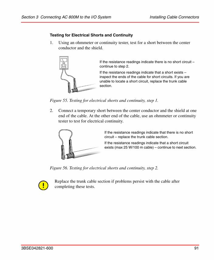
Section 3 Connecting AC 800M to the I/O System Installing Cable Connectors
3BSE042821-600 91
Testing for Electrical Shorts and Continuity
1. Using an ohmmeter or continuity tester, test for a short between the center conductor and the shield.
2. Connect a temporary short between the center conductor and the shield at one end of the cable. At the other end of the cable, use an ohmmeter or continuity tester to test for electrical continuity.
Figure 55. Testing for electrical shorts and continuity, step 1.
Figure 56. Testing for electrical shorts and continuity, step 2.
Replace the trunk cable section if problems persist with the cable after completing these tests.
If the resistance readings indicate there is no short circuit – continue to step 2.
If the resistance readings indicate that a short exists – inspect the ends of the cable for short circuits. If you are unable to locate a short circuit, replace the trunk cable section.
If the resistance readings indicate that there is no short circuit – replace the trunk cable section.
If the resistance readings indicate that a short circuit exists (max 25 W/100 m cable) – continue to next section.

Installing Cable Connectors Section 3 Connecting AC 800M to the I/O System
92 3BSE042821-600
Attaching the Connectors to the Cable
1. Slip the crimp ferrule onto the cable. Push it back to the sheath area of the cable to keep it out of the way for the moment.
2. Place the center pin over the center conductor.
3. With the center pin in place, use the crimp tool to crimp the pin into place.
Figure 57. Slip the crimp ferrule onto the cable.
Figure 58. Place the center pin over the center conductor.
Make sure that the center pin slips onto the center conductor completely. The back shoulder of the center pin should be up against the white insulation. If it is not, recheck the length of the center conductor.
Stripped cable
Crimp ferrule
Center pin
Center conductor

Section 3 Connecting AC 800M to the I/O System Installing Cable Connectors
3BSE042821-600 93
4. Slide the ControlNet connector onto the cable.
Figure 59. The smaller hexagonal crimping notch is for crimping the center pin onto the center connector.
Figure 60. Slide the ControlNet connector onto the cable.
Braid and tape shieldConnector base
Connector

Installing Cable Connectors Section 3 Connecting AC 800M to the I/O System
94 3BSE042821-600
5. Move the connector in a circular motion (without any inward pressure) to work the connector base underneath the three outer shields. Once a gap has opened up between the inner shield tape and the three outer shields, start applying inward pressure to seat the connector base under the three outer shields (braid/tape/braid).
6. Slide the crimp ferrule over the three outer shields and connector base until it meets the shoulder of the connector.
Figure 61. The wire is pliable and may fray slightly.
Figure 62. Slide the crimp ferrule into place.
Note that the center pin, when installed in the connector, must be sufficiently pushed forward. If the visible part of the center pin is too short then a reliable connection can not be guaranteed. See Figure 62 to get an estimation of the position of the center pin.
Crimp ferrule

Section 3 Connecting AC 800M to the I/O System Installing Cable Connectors
3BSE042821-600 95
7. Using the crimp tool, crimp the ferrule. Position the crimp tool on the ferrule as close as possible to the connector base and ferrule meeting line. Press the tool tightly around the ferrule until the crimp tool allows release.
Testing for Electrical Shorts and Continuity
1. Using an ohmmeter or continuity tester, test for a short between the connector body and pin.
Figure 63. The larger hexagonal crimping notch is for crimping the ferrule which holds the connector to the cable.
Many network problems are due to improperly installed connectors. All cables ends must have tight fitting connectors. Pull the connector to verify that it is attached. If it is loose or comes off, snip off the connector and install a new one.
Figure 64. Testing for electrical shorts and continuity, step 1.
Crimp ferrule
Ohmmeter
Connector body
Pin
If the resistance readings indicate that there is no short circuit – continue to next section.
If the resistance readings indicate that a short exists – use your wire cutters to cut off the connector, install a new connector and begin testing again.

Installing Cable Connectors Section 3 Connecting AC 800M to the I/O System
96 3BSE042821-600
2. Connect a temporary short between the pin and connector body at one end of the cable. At the other end of the cable, use an ohmmeter or continuity tester to test for electrical continuity.
TDR Measurement
A very useful tool to document and verify a ControlNet installation is the time domain reflectometer (TDR). There are a number of testers on the market with varying features and benefits. Often they can also be used for twisted pair cables in addition to different kinds of coax and twinaxial cables.
The TDR sends a fast rise time pulse down the cable and measures the intensity of reflections. Its output is typically an oscilloscope-like screen or a printout. The greatest reflection indicates the end of an unterminated cable. Earlier reflections could indicate changes in crimping, stretching, corrosion, or breaks in shielding and other defects which are often visually undetectable. Also the location and quality of connectors and taps can be estimated.
Commercially available testers often combine different measurement methods to automatically render an overall pass/fail result in addition to the individual test results regarding:
• DC loop resistance,
• cable length,
Figure 65. Testing for electrical shorts and continuity, step 2.
Replace the trunk cable section if problems persist with the cable after completing these tests.
Connector body If the resistance readings indicate that there is no short – use your wire cutters to cut off the connector, install a new connector and begin testing again.
If the resistance readings indicate that a short exists (max 25 W/100 m cable) – continue to next section.

Section 3 Connecting AC 800M to the I/O System Installing Cable Connectors
3BSE042821-600 97
• capacitance,
• attenuation,
• relative impedance along the cable.
To perform an auto test, it is necessary to specify the cable used. If the tester does not allow you to immediately select the manufacturer and the cable type, you must enter a number of parameters such as nominal impedance, capacitance and velocity of propagation.
Automatic testers usually have a main unit to be connected to one end of the cable segment under test, and a remote unit to be connected to the other end. The remote unit changes the termination between shorted, open or matching resistance depending on the actual measurement ordered from the main unit. It can also send a signal of known amplitude from the far end of the cable to be measured by the main unit at the near end.
After installation, test each trunk cable section of any substantial length individually, to make possible a detailed verification of changes when required. To be able to quickly find defective areas you may also record measurements of complete segments including taps with integral drop cables.
Figure 66. Example of a TDR with main unit (1) and remote unit (2).
12

Installing Cable Connectors Section 3 Connecting AC 800M to the I/O System
98 3BSE042821-600
Connect the test units to the end taps of the cable segment after the terminators have been removed. If convenient, you can split the segment where appropriate and test each part separately. This may be necessary due to the limited measuring range of the TDR, often 0–600 m.
If taps and drop cables are included in the segment being tested, the cable length measurements will show a value about 1.4 m too large per connected tap. The measurements are, however, reproducible if performed in exactly the same way, and therefore useful for troubleshooting. If you need more accurate measurements, you can replace the taps with bullet connectors, see page 64.
Documentation and Verification
System verification begins with installation. Even the smallest system needs to be documented when it is installed, so records are available when it fails or is to be modified. The documentation should include wiring maps showing all taps and connected devices, and all cables and wires should be carefully labeled. Before
It is necessary to disconnect all devices from the drop cables before the cable segment is tested.
Figure 67. Normal trace of the relative impedance along a single trunk cable section.
Ohm
m
75

Section 3 Connecting AC 800M to the I/O System Connecting Cable Sections
3BSE042821-600 99
start-up, a certification test of the cable system should be performed by means of TDR, with careful recording of results, and of procedures and parameters used.
Connecting Cable Sections
Connect the cable sections to the tap’s BNC connectors.
Terminating the Segment
The taps on the ends of the segment have only one cable connector attached to them. This leaves an open, or unterminated, end on the segment, see Figure 69. Signals transmitted along the cable will reflect off these unterminated ends and interfere with transmission.
To eliminate signal reflections from the ends of the segment, you must attach a 75 terminator to the first and last taps on the segment, see Figure 70. The terms “first” and “last” refer to the physical location of the node along the trunk cable.
Repeat at the other end of the segment.
It is a good practice to survey the cable system and its documentation together with the installation people, writing a detailed standardized report which lists the integral components with notes of acceptance and complaints.
Figure 68. Connecting cable sections

Installing Repeaters Section 3 Connecting AC 800M to the I/O System
100 3BSE042821-600
Figure 69. Connect one end of the trunk cable section to one of the tap’s BNC connectors.
Figure 70. Install a 75 terminator onto the tap’s other BNC connector.
Installing Repeaters
Use the mounting dimensions provided (see “Mounting Dimensions” on page 181) to mount the repeater horizontally or vertically in the selected area.
The repeater should be mounted to meet the following conditions:
• Air has to be able to flow in/out of the air holes on the top and bottom of the repeater. For proper ventilation, make sure there is a minimum of 5 cm from surrounding equipment.
• Mounted in an enclosure (e.g. NEMA) to provide protection from dust, moisture or corrosive atmospheres.
• Mounted to a grounded metal plate if possible.

Section 3 Connecting AC 800M to the I/O System Installing Repeaters
3BSE042821-600 101
Ground the Repeater
Use a wire (e.g. #14 AWG) to connect the repeater to the ground bus.
Connect Power and Relay Circuitry
1. Remove the terminal strip cover, see Figure 72.
2. Connect the power to the repeater, see Figure 73.
3. Replace the terminal strip cover.
Figure 71. Ground the repeater
Nut
Ground lug
Star washer
Grounding stud

Installing Repeaters Section 3 Connecting AC 800M to the I/O System
102 3BSE042821-600
Figure 72. Removal of the terminal strip cover.
Figure 73. Connection of the power to the repeater.
Relay contact which opens at a fault condition.
RPT RPTD

Section 3 Connecting AC 800M to the I/O System Installing Repeaters
3BSE042821-600 103
Connecting the Repeater to the ControlNet Segments
1. Remove (and save) the dust cap located on the straight or right-angle connector of the designated tap on the first segment (segment 1), see Figure 74.
If you disconnect the tap from the repeater, place the dust cap back on the straight or right-angle connector to prevent the connector from accidentally contacting a metallic grounded surface.
Figure 74. Remove the dust cap from the connector for segment 1.
2. Remove and discard the dust caps from the repeater’s BNC jacks.
3. Connect the straight or right angle connector of the tap to the BNC connector of the repeater, see Figure 75.
Figure 75. Connect the first tap to the repeater.
Do not allow any metal portions of the tap to contact any conductive material. This may cause noise on the network.
Segment 1Tap
Dust cap
Segment 1
Tap

Installing Repeaters Section 3 Connecting AC 800M to the I/O System
104 3BSE042821-600
4. Remove (and save) the dust cap located on the straight or right angle connector of the designated tap on the second segment (segment 2).
Figure 76. Remove the dust cap from the connector for segment 2.
5. Connect this tap’s straight or right angle connector to the BNC connector of the repeater.
Figure 77. Connect the second tap to the repeater
Installing Coax Repeaters, Example 1
In this network example:• Segments 1 and 4 each have 2 taps, and each = 1000 m,• segments 2 and 3 each have 3 taps, and each = 983 m,• the cable length between end nodes = 3966 m (1000+2×983+1000),• there are 3 repeaters in series (A, B, C).
Segment 2Tap
Dust cap
Segment 1Segment 2
Tap
Tap

Section 3 Connecting AC 800M to the I/O System Installing Repeaters
3BSE042821-600 105
Table 11 indicates an actual propagation delay of 26 s. If network update time (NUT) is 5 ms and the highest node address (Smax) is 20, Table 12 indicates a maximum allowed propagation delay of 50 s, which is well above the actual value.
Installing Coax Repeaters, Example 2
When repeaters are installed as described below, there can be a maximum of 48 repeaters in segment 4.
In this network example:• Segment 4, having 3 repeaters in parallel, is max 983 m,
Figure 78. Installing coax repeaters, example 1.
Segment 1 Segment 2
Repeater A Repeater B
Segment 3Segment 4
End node 1
End node 4
Repeater C

Connecting Devices Section 3 Connecting AC 800M to the I/O System
106 3BSE042821-600
• if there are 10 nodes (i.e. 11 taps) in each of segments 1, 2, and 3, they cannot exceed 853 m each (only two taps are shown in the figure below),
• the cable length between end nodes is 2689 m (983+2×853),• there are 2 repeaters i series.
Calculate, using the formula in “Network Parameters” on page 75, or interpolate in Table 11 gives an actual propagation delay of 18 s. If the network update time (NUT) is 5 ms and the highest node address (Smax) is 30, Table 12 indicates a maximum allowed propagation delay of 31 s, which is well above the actual value.
Figure 79. Installing coax repeaters, example 2.
Connecting Devices
After terminating the segments, connect the devices.
1. Remove and discard the tap’s dust cap (located on the straight or right angle connector).
2. Connect the tap’s straight or right angle connector to the device.
Segment 4
Segment 1 Segment 2 Segment 3
End node 1 End node 3

Section 3 Connecting AC 800M to the I/O System Installing the Fiber Optic System
3BSE042821-600 107
Installing the Fiber Optic System
Fiber Optic Cable
Let specialists take the full responsibility to choose cable types suitable for the actual installation with regard to the need for moisture and flame resistance, high- and low temperature exposure, tensile strength, armouring, etc. Let also trained personnel install the cable system and terminate it, following the supplier’s installation instructions.
The installation should include complete documentation of cable routing and the position of every cable strand connection.
Local equipment can be connected to the nearest connector panel by less experienced people using interconnect cables which have been purchased ready-terminated in required lengths.
Power Loss Measurement
After installation, test each fiber cable section by means of an optical power meter to assure the total attenuation to be less than 13.3 dB at 1300 nm. Connect a 1300 nm optical light source to one end of one strand of the cable section. Connect the other end of the same strand to an optical power meter and read the attenuation. Exchange the two units to measure from the opposite direction. Keep records of the attenuation for each cable section strand. This is invaluable for future maintenance and troubleshooting of the network.
Observe the minimum cable bend radius specified. Do not touch the ends of the fiber optic strands and do not let the ends come in contact with dust, dirt or other contaminants. Always put protective caps onto fiber cable connectors and fiber ports when they are disconnected. If the ends become contaminated, clean them with a soft, clean, lintless cloth and alcohol.
Do not look directly into the fiber ports. Light levels may cause damage to eyesight.

Fiber Optic Cable Section 3 Connecting AC 800M to the I/O System
108 3BSE042821-600
Considerable power loss may indicate:
• Poor splices,
• bending losses,
• broken fibers,
• poor connections,
• dust or dirt.
OTDR Measurement
In addition to power loss measurement, it is recommended to examine the total fiber network by means of an optical time domain reflectometer (OTDR). This instrument emits light into a strand of a fiber cable and displays the reflected light.
Figure 80. Power meter (1) and 1300 nm light source (2).
Figure 81. Example of an optical time domain reflectometer.
2
1

Section 3 Connecting AC 800M to the I/O System ControlNet Fiber Units
3BSE042821-600 109
From the traces the following information can be obtained:
• Total distance along the cable to the other end or to a fiber break.
• Distance to an event which attenuates the light, such as a splice, a bend, or a connector. Also the distance between two such events can be measured.
• Light attenuation between two points of the cable.
• Total reflected light or light reflected from a single event.
Figure 82. Trace with the marker indicating the total cable length.
OTDR instruments differ regarding features and benefits. Some offer, for instance, built in printer and software for trace analysis and trace comparison.
ControlNet Fiber Units
The fiber repeater adapter (RPA) and the fiber repeater unit (RPFM or RPFS) are used to incorporate fiber optic links on a coax network. They are mounted on a DIN rail 35×7.5 mm according to the EN 50022 standard.
It is necessary to disconnect fiber units (RPFMs) from the fiber cable before it can be tested.
Keep records of the traces for each cable section strand in form of hardcopy printouts or disk files. This is invaluable for future maintenance and troubleshooting of the network. Observe “Documentation and Verification” on page 98.
dB
km
1.1285 km

ControlNet Fiber Units Section 3 Connecting AC 800M to the I/O System
110 3BSE042821-600
1. Position the unit at a 30° angle. Hook the lip at the rear of the unit onto the top of the DIN rail, and rotate the unit onto the rail.
Figure 83. Installing ControlNet fiber units, step 1.
2. Press the unit down to the DIN rail until flush. The locking tab should snap into position and lock the unit to the DIN rail. If not, use a screwdriver to move the locking tab down while pressing the unit. Release the locking tab to lock the unit in place. If necessary, push up on the locking tab to lock.
3. Up to four repeater units can be mounted on the DIN rail and plugged together with the repeater adapter. Remove the protective backplane caps from the connectors that will be used. Attach a repeater unit to the rail and slide it to the left to mate with the repeater adapter or another repeater unit, see Figure 85.
Figure 84. Installing ControlNet fiber units, step 2.
Make certain that the adapter and repeater units are secured together with DIN rail anchors. Failure to do so may result in the loss of communications and/or cause damage to the units.

Section 3 Connecting AC 800M to the I/O System ControlNet Fiber Units
3BSE042821-600 111
When installing the units, observe the environmental specifications in Appendix C, Technical Specifications. Also avoid high electrostatic and electromagnetic fields, corrosive and inflammable gases, dust, conductive particles, oil mist and organic solutions. The units must not be exposed to water or to direct sunlight. It is recommended to mount the units in an enclosure, for instance type NEMA. Allow for a minimum space of 5 cm from surrounding equipment to achieve proper ventilation.
The total number of units that can be attached to the repeater adapter can not exceed four or the total power consumption of the units can not exceed 1.6 A at 5 V DC, whichever comes first.
Do not insert or remove units with power connected to the attached repeater adapter.
Figure 85. Installing ControlNet fiber units, step 3.
If you exceed the unit or power limit, you may cause damage to the repeater adapter and units.

Repeater Adapter RPA Section 3 Connecting AC 800M to the I/O System
112 3BSE042821-600
Repeater Adapter RPA
To connect the adapter:
1. Connect the coax network drop cable to the BNC connector.
2. Connect the +24 V DC input to terminal A of the connector by inserting a screwdriver into the slot and prying up so the clamp is opened enough to accept the wire.
3. In the same way, insert the common wire into terminal C.
4. Terminals B (+24 V DC) and D (common) can be used to pass the power to other units. Terminals E and F are reserved for future use.
Figure 86. Power terminals A-D, and indications for coax connector (1) and fiber channels (2).
Make sure all fiber units are attached and secured prior to applying power to the adapter.
1 2DCBA

Section 3 Connecting AC 800M to the I/O System Fiber Units RPFM and RPFS
3BSE042821-600 113
Fiber Units RPFM and RPFS
To connect the unit:
1. Remove the protective caps from the fiber connectors that will be used and save the caps in a clean place for future use.
2. Align the knob of the ST cable connector with the groove of the receive connector A, insert it and turn to lock it.
3. In the same way, insert the relevant cable connector into the transmit connector B.
4. Connect the other ends of the fiber cable to channel 1 or 2 of another fiber unit.
Figure 87. Fiber channels (1) and (2), receive connectors (A) and transmit connectors (B).
A A
B
B
1A B
2

Fiber Units RPFM and RPFS Section 3 Connecting AC 800M to the I/O System
114 3BSE042821-600
Installing Fiber Repeaters, Example 1
The configuration below is equivalent to example 1 on page 104, but with fiber repeaters instead of coax repeaters.
Figure 88. Connection of two fiber units.
Be sure the fiber connected to A (receive) on one RPFM or RPFS is connected to B (transmit) on the other RPFM. Channel 1 or channel 2 can be used on either unit. Never connect the fiber cable between channel 1 and 2 on the same RPFM, or between channels on different RPFMs attached to the same RPA.
Figure 89. Installing fiber repeaters, example 1
RPA RPFM/RPFS
CH1 CH2
A B A B
RPA
CH1 CH2
A B A B
RPFM/RPFS
200-RACN
RPA RPFM/RPFS
200-RACN CI865 200-RACN 200-RACN
Fiber optic cable Fiber optic cable Fiber optic cable
Coax segment 1 Coax segment 2 Coax segment 3 Coax segment
End node 1 End node 4
RPA RPFM/RPFS
RPA RPFM/RPFS
RPA RPFM/RPFS

Section 3 Connecting AC 800M to the I/O System Fiber Units RPFM and RPFS
3BSE042821-600 115
In this network example:
• Coax segments are 300 m each,
• fiber optic cables are 4.8 km each,
• the cable length between end nodes is 15 km,
• there are 4 repeaters in series.
Table 11 indicates 83 s propagation delay. Since one node is 200-RACN, network update time (NUT) must be set to 5 ms. If the highest node address (Smax) is 10, Table 12 indicates a maximum allowed propagation delay of 106 s, which is above the actual value.
Installing Fiber Repeaters, Example 2
The configuration below is equivalent to example 2 on page 105, but with fiber repeaters instead of coax repeaters. The repeater hub (4) is the center of the star configuration, corresponding to the segment 4 on page 105.
In this network example:
• Coax segment 1 and 2 are both 500 m,
• coax segment 3 is 100 m,
• fiber optic cable 1 is 3 km,
• fiber optic cable 2 is 100 m.
Figure 90. Installing fiber repeaters, example 2
200-RACN200-RACN200-RACN CI865
Coax segment Coax segment 3
Fiber optic cable 1 Fiber optic cable 2
Coax segment
1 2 3
4RPA RPFM/RPFS
RPA RPFM/RPFS
RPFM/RPFS
RPA RPFM/RPFS

Connecting the Satt I/O Units and CI865 Section 3 Connecting AC 800M to the I/O System
116 3BSE042821-600
The total cable length between fiber units (1) and (3) is 3.7 km with 3 repeaters in series. The longest (and relevant) cable distance is however between fiber units (1) and (2). The total cable length between these units is 4 km and there are 2 repeaters in series. Table 11 indicates 25 s propagation delay.
If network update time NUT = 5 ms, the highest node address allowed isSmax = 32, indicated by Table 12, or the formula on page 79:
Max. allowed propagation delay = 225×(5/32) - 6.4 = 25,7 s
Note that the CI865 does not allow more than 32 nodes (where each node must be designated a unique address between 01 and 99) and that Smax should be kept as low as possible to optimize network performance.
Connecting the Satt I/O Units and CI865This section describes how to connect the ControlNet to the BNC connector of the I/O systems and the CI865.
The BNC connector is located:
• Rack I/O - at the rear of the 200-RACN unit, see Figure 91.
• Series 200 I/O - at the front of the 200-ACN unit, see Figure 92.
• CI865 - at the front of the CI865 unit.
1. Select a suitable location for the tap within one meter from the ControlNet BNC connector. When selecting the tap location, keep in mind the routing of the drop and trunk cables. They should not be routed close to high-voltage cables. Avoid bending the trunk cable too much. Distance from high-voltage cables and other important information about ControlNet installation is given in Section “Application Installation Considerations” on page 66.
2. The tap can be mounted in various ways, for example using a DIN rail or screwed into a suitable structure, see Figure 91 for an example. Even if the tap is not mounted on a DIN rail, the universal mounting bracket should be used to avoid galvanic connection to a conducting structure. For example, the tap can be mounted on the cabinet door frame on the side of the frame that is closest to the cabinet hinge, see Section “Mounting the Taps” on page 81.

Section 3 Connecting AC 800M to the I/O System Connecting the Satt I/O Units and CI865
3BSE042821-600 117
3. Connect the tap drop cable to the BNC connector. Before starting up the system, all ControlNet cable connections should be tested. Check the pulling strength of applied connectors. Test for short circuits and open circuits using resistance measurements.
Figure 91. Mounting of the ControlNet tap and the connection to 200-RACN.
4. Define the network node address:
• Rack I/O - by turning the two switches (x10 and x1) on front of the 200-RACN unit to the correct position. A node address in the range 02-99 should be selected for the 200-RACNs, see Section “Rack Adapter Board, 200-RACN” on page 121. Example: Node address 04 should be defined. Set the switch ”x10” to 0 and switch ”x1” to 4.
• Series 200 I/O - by clicking the push button switches on the front of the200-ACN unit, see Figure 92. A node address in the range 02-99 should be selected for the 200-ACNs.
• CI865 - The node address is fixed to 01.
It is highly recommended to select addresses in a consecutive manner to minimize network load, see “Node Address Switches” on page 123.
BNCconnector

Connecting the Satt I/O Units and CI865 Section 3 Connecting AC 800M to the I/O System
118 3BSE042821-600
Figure 92. The push button switches on the 200-ACN to change its node address.
BNC-connector

3BSE042821-600 119
Appendix A Limitations
ControlNet• A maximum of 32 nodes per network is allowed: The CI865, the 200-ACN
adapters (slaves) and the rack-based 200-RACN can share these number of nodes.
– One (1) ControlNet node must be assigned for the CI865 unit.
– A maximum of eight (8) nodes can be assigned for 200-RACN.
– The remaining nodes can be assigned to the 200-ACN.
– Each node must be designated a unique address. The node address 01 is reserved for the CI865. The 200-RACN nodes and 200-ACN nodes can be addressed between 02 and 99.
• Maximum cable length without repeaters:
– 1000 meters with coax cable.
– Fiber optic links can be included to increase network length and obtain galvanic isolation. The length can be increased to about 7000 meters.
• Number of repeaters:
– 5 (maximum) in series
– 6 segments (5 repeaters) in series
– 48 segments in parallel
• Maximum cable length with repeaters:
– 5000 meters (coax) at 5 Mbit/s
– At least 30 km (optical fiber)
Support for Rack I/O Appendix A Limitations
120 3BSE042821-600
Support for Rack I/OEvery rack gets the same settings of the I/O board addresses. All other methods of I/O board addressing than described in the subsection I/O Addressing on page 49 are not supported. This prerequisite affects expansion I/O racks (racks equipped with PBAD or PBX units) and I/O racks equipped with SLS which are not supported by Satt ControlNet. When the PBAD and PBX units are replaced with 200-RACN units the I/O board addresses may need to be changed to fit the supported addressing method.
EtherNet/IP LimitationsRefer to the AC 800M EtherNet/IP DeviceNet Configuration (9ARD000014*) manual for limitations.

3BSE042821-600 121
Appendix B I/O Board Installation andFunction
This appendix describes the installation and function of the I/O boards and other units to be used with the rack-based I/O system. See Rack I/O section of Appendix C, Technical Specifications for additional technical information about the I/O boards.
Rack Adapter Board, 200-RACNThe rack adapter board, 200-RACN, handles the communication between system AC 800M and the remote rack-based I/O system via ControlNet.
There are two versions of the rack adapter board: 200-RACN and 200-RACN/A. The latter is equipped with a central A/D converter (ADSF). It is used if analog signals are to be connected to the I/O system.
A 200-RACN (or 200-RACN/A) can control 16 Rack I/O boards corresponding to 512 digital I/O signals.
The power supply part of 200-RACN (200-RACN/A) takes its power from the power supply PSF, and generates the required internal voltages.
The 200-RACN (200-RACN/A) board should be fitted between the last I/O board position and the PSF power supply unit in the central rack.
Because of the risk of electrostatic discharge, we recommend that you wear an ESD bracelet when handling the boards.

Rack Adapter Board, 200-RACN Appendix B I/O Board Installation and Function
122 3BSE042821-600
Indicators
Indicator LED status Function
OK Off
Flashing green
Solid green
Flashing red
Solid red
No power or resetSelf-test OK but no connection established with the system.
On-line, link OK, connected.
Recoverable fault, e.g. erroneous board configuration is detected.
Self-test error, rack error or I/O board error.
Note 1: OK indication will be lit at start up during self-test.
Note 2: If an I/O board- or I/O rack error is detected, the I/O copy will be terminated. Then the STOP indication will also be lit.
POWER Off
Solid green
Power off
Power applied
STOP Off
Solid red
I/O copy running
No I/O copy is performed, i.e. I/O copy has not started yet, or watchdog time-out due to hardware failure.
Com A and B simultaneously
Off
Flashing red-green
Flashing red
Solid red
No power or reset
200-RACN self-test
Node configuration error, i.e. duplicated node address.
Hardware failure
Com A(B disabled)
Off
Solid green
Flashing green
Flashing red
Solid red
No power or reset
Channel OK
Temporary network error (communication error or network configuration not downloaded.
Cable fault or lone node
Board failure

Appendix B I/O Board Installation and Function Rack Adapter Board, 200-RACN
3BSE042821-600 123
Mode switch
For normal applications there is no choice. The switch must always be in position 0 (the other positions are used for test purposes).
Node Address Switches
The network node address is defined by 2 rotary switches. The address can be set between 02 and 99. It is recommended that addresses be selected in a consecutive manner, i.e. 02, 03, 04 etc.
Connections
• 200-RACN is connected to ControlNet through the BNC coaxial connector located at the rear of the board.
• A 9-pin female D-sub type connector on the front may be used for asynchronous serial RS232 communication. It is used for test purposes and fault diagnosis.
• Network Access Port, NAP with an RJ-style connector. It is used for test purposes and is normally unconnected.
Indication Function
X10 Most significant part of node address
X1 Least significant part of node address
The node address 01 can physically be set on the rotary switch, but must not be used, since it is used by the CI865.
Pin Function
2 Receive data (out)
3 Transmit data (in)
5 Ground
7 Request to send (out)
8 Clear to send (in)
1, 4, 6, 9 Not connected

Mounting the Analog-to-digital Converter, ADSF Appendix B I/O Board Installation and Function
124 3BSE042821-600
Mounting the Analog-to-digital Converter, ADSF
When analog signals are processed, ADSF is used to convert the analog signals to digital signals. ADSF is mounted on the lower part of the rack adapter board, 200-RACN, see Figure 93.
Figure 93. ADSF - analog-to-digital converter mounted on rack adapter board, 200-RACN.
Proceed as follows to mount ADSF on the rack adapter board, 200-RACN:
1. Loosen the two screws in the distance pillars on each side of the X2 connector.
2. Position ADSF over the X8 connector on the 200-RACN board and press firmly to ensure proper contact with the connector pins. The component sides of the boards must be facing each other.
3. Tighten the two screws in the distance pillar so that the ADSF board is held firmly in position.
X2
ADSF
X8

Appendix B I/O Board Installation and Function Power Supply Unit, PSF
3BSE042821-600 125
Power Supply Unit, PSFPSF is a power supply unit for the PIOS35 rack. The unit can be powered either by a 230 V AC or a 24 V DC supply and produces outputs of 5 V DC and 12 V DC, together with a power failure signal. The maximum load when supplied with 230 V AC is 50 W, and the maximum load when supplied with 24 V DC is 70 W.
Indicators
The front panel includes indicators for the +5 V, +5 VL and +12 V supplies and a Power Failure indicator which lights up when the power supply falls below the permitted lower limit.
Connections
For connection of the mains supply cables on the rear of the rack, see "Handling the Mains Supply", on page 51. PSF is connected automatically after being mounted and secured in the extreme right rack position.
Description
PSF is a power supply unit which is supplied either from the mains via a toroid transformer, or from a separate 24 V DC power unit.
There is no galvanic separation for a 24 V DC source but a mains supply source is separated by the transformer.
The voltage regulators are mounted on the front panel which serves as a heat sink.
Test points for the +5 V DC, +5 VL and +12 V DC outputs are provided on the front panel.
Indicators Function
+5V Green when the supply voltage is present.
+5VL Green when the supply voltage for LED’s on I/O board is present.
+12V Green when the supply voltage is present.
POWER FAIL Red when input power is low.
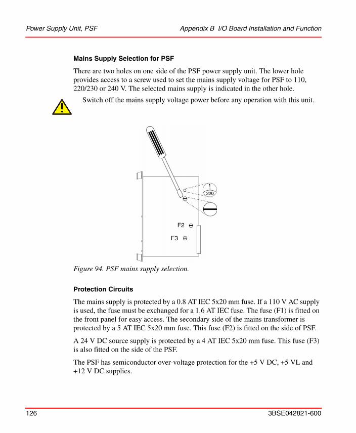
Power Supply Unit, PSF Appendix B I/O Board Installation and Function
126 3BSE042821-600
Mains Supply Selection for PSF
There are two holes on one side of the PSF power supply unit. The lower hole provides access to a screw used to set the mains supply voltage for PSF to 110, 220/230 or 240 V. The selected mains supply is indicated in the other hole.
Figure 94. PSF mains supply selection.
Protection Circuits
The mains supply is protected by a 0.8 AT IEC 5x20 mm fuse. If a 110 V AC supply is used, the fuse must be exchanged for a 1.6 AT IEC fuse. The fuse (F1) is fitted on the front panel for easy access. The secondary side of the mains transformer is protected by a 5 AT IEC 5x20 mm fuse. This fuse (F2) is fitted on the side of PSF.
A 24 V DC source supply is protected by a 4 AT IEC 5x20 mm fuse. This fuse (F3) is also fitted on the side of the PSF.
The PSF has semiconductor over-voltage protection for the +5 V DC, +5 VL and +12 V DC supplies.
Switch off the mains supply voltage power before any operation with this unit.
F2
F3

Appendix B I/O Board Installation and Function Digital Input Boards, IDPG24 and IDPG48
3BSE042821-600 127
Digital Input Boards, IDPG24 and IDPG48IDPG is a digital input board for 32 DC inputs using positive logic. The inputs are galvanically separated using optocouplers. The board is available in two versions for signal levels of 24 and 48V.
IDPG may be used in applications where the 0 V level of the process is not connected to the 0 V level of the system, or where there is a special requirement for galvanic signal separation. IDPG is used to interface signals from devices such as limit switches, photocells, etc.
Indicators
The state of each input is indicated by a LED on the front panel. This is lit when the input is activated. The address of each input is shown next to the LED.
Switch
The switch on the front panel should normally be in the ”I” position. When the board is installed or exchanged, the switch should be in the ”0” position. The input status is then frozen in the central unit.
Connections
The upper connector at the rear of the board, the X1 connector, is used for process connection. The corresponding connector is at the rear of the I/O rack. All signal cables are connected to the X1 connector on the I/O rack by means of crimp sleeves.
Pin d b z
Input number
2 01 0 V(1) 00
4 03 0 V(1) 02
6 05 0 V(1) 04
8 07 0 V(1) 06
10 11 0 V(1) 10
12 13 0 V(1) 12
14 15 0 V(1) 14
16 17 0 V(1) 16

Digital Input Boards, IDPG24 and IDPG48 Appendix B I/O Board Installation and Function
128 3BSE042821-600
Figure 95. Block diagram IDPG24 or IDPG48.
18 21 0 V(1) 20
20 23 0 V(1) 22
22 25 0 V(1) 24
24 27 0 V(1) 26
26 31 0 V(1) 30
28 33 0 V(1) 32
30 35 0 V(1) 34
32 37 0 V(1) 36
(1) Separated 0 volt for each pair of inputs (00-01, 02-03…), see Figure 95.
Input 00
Input 36Multiplexer
Switch
Powersupply
Input 01
Input 37

Appendix B I/O Board Installation and Function Digital Input Board, IAPG230
3BSE042821-600 129
Digital Input Board, IAPG230IAPG230 is a digital input board for 16 AC inputs (230 V) using positive logic. The inputs are galvanically separated by optocouplers.
IAPG230 is used to interface signals from devices such as power switches, relay contacts, etc.
Indicators
The state of each input is indicated by a LED on the front panel. This is lit when the input is activated. The address of each input is shown next to the LED.
Switch
The switch on the front panel should normally be in the ”I” position. When the board is installed or exchanged, the switch should be in the ”0” position. The input status is then frozen in the central unit.
Connections
The upper connector at the rear of the board, the X1 connector, is used for process connection. The corresponding connector is at the rear of the I/O rack. All signal cables are connected to the X1 connector on the I/O rack by means of crimp sleeves
.
Pin d b z
Input number
2 00 00
4 01 01
6 02 02
8 03 03
10 04 04
12 05 05
14 06 06
16 07 07
18 10 10
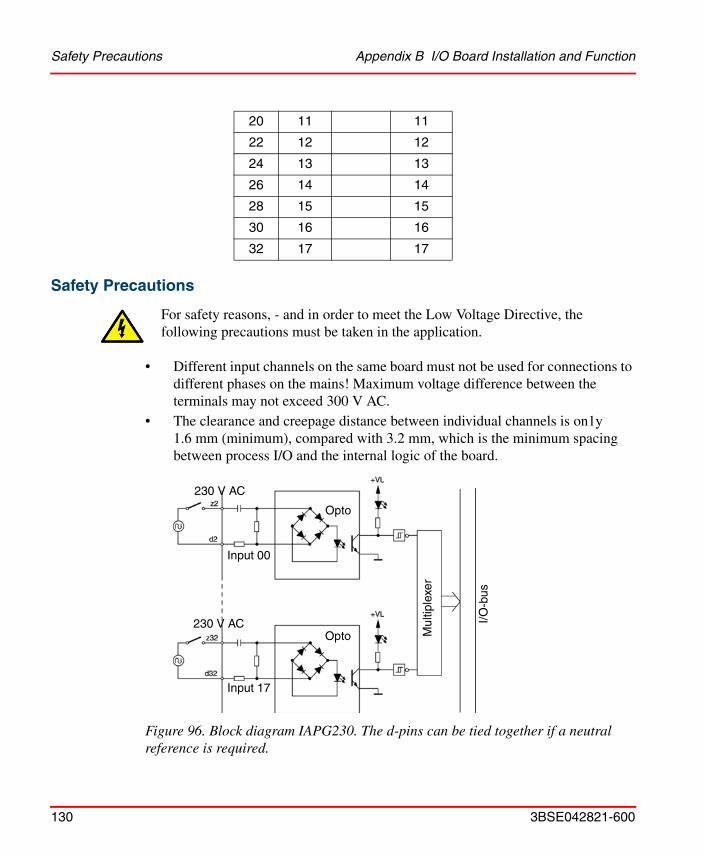
Safety Precautions Appendix B I/O Board Installation and Function
130 3BSE042821-600
Safety Precautions
• Different input channels on the same board must not be used for connections to different phases on the mains! Maximum voltage difference between the terminals may not exceed 300 V AC.
• The clearance and creepage distance between individual channels is on1y 1.6 mm (minimum), compared with 3.2 mm, which is the minimum spacing between process I/O and the internal logic of the board.
Figure 96. Block diagram IAPG230. The d-pins can be tied together if a neutral reference is required.
20 11 11
22 12 12
24 13 13
26 14 14
28 15 15
30 16 16
32 17 17
For safety reasons, - and in order to meet the Low Voltage Directive, the following precautions must be taken in the application.
Input 00
230 V AC
Opto
Mul
tiple
xer
I/O-b
us
230 V AC
Input 17
Opto

Appendix B I/O Board Installation and Function Digital Output Board, ODPG.8
3BSE042821-600 131
Digital Output Board, ODPG.8ODPG.8 is a digital output board for DC voltage with 32 optocoupled outputs, divided into four separate groups of eight. The maximum output capacity is 0.8 A per output, subject to a maximum of 3.2 A per group, and 8 A for the entire board.
ODPG.8 is constructed for supply voltages between 10 and 60 V. Since the four groups are completely separated from each other, it is possible to use four different supply voltages for the same board.
Several outputs can be connected to the same load if they are fed from the same voltage source. If not, a protective diode is required in series with the output.
Fully loaded boards should preferably not be fitted next to each other in the rack. If this cannot be avoided the rack may be fitted with a cooling fan. See ”Operating temperature” in "General Technical Specifications", on page 185.
Indicators
There are 32 red LED's on the front of the board for status indication of their outputs. The octal address of the output is marked next to each LED.
Switch
Normally, the switch on the front panel should be in the ”I” position.
When the board is installed or exchanged, the switch should be set to the ”0” position. In this position, the outputs are reset to zero.
Connections
The upper connector at the rear of the board, the X1 connector, is used for process connection. The corresponding connector is at the rear of the I/O rack. All signal cables are connected to the X1 connector on the I/O rack by means of crimp sleeves.
Ground Reference
0 V DC for the outputs and supply must be referenced to ground, either directly or through a bipolar capacitor of 0.01 µF and with a voltage rating above the potential

Digital Output Board, ODPG.8 Appendix B I/O Board Installation and Function
132 3BSE042821-600
difference between 0 V DC and ground (e.g. use Phoenix TT-SLKK 5-C 12n 230 AC). This is required to meet the specified interference standard.
Figure 97. Connector X1. Max. 5 A may go through a pin in the X1 connector.
Pin d b z Comments
24
01
03
+U 00 -
07
00
02
b2-4 power supply for output 00-07
68
05
07
10-
17
04
06
b6-8 power supply for 10-17
1012
11
13
20-
27
10
12
b10-12 power supply for 20-27
1416
15
17
30 -
+U 37
14
16
b14-16 power supply for 30-37
1820
21
23
0 V 00-
07
20
22
b18-20 0 V for output 00-07
2224
25
27
10-
17
24
26
b22-24 0 V for 10-17
2628
31
33
20-
27
30
32
b26-28 0 V for 20-27
3032
35
37
30-
0 V 37
34
36
b30-32 0 V for 30-37

Appendix B I/O Board Installation and Function Digital Output Board, ODPG.8
3BSE042821-600 133
Figure 98. Block diagram ODPG.8

Relay Output Board, ORG24 Appendix B I/O Board Installation and Function
134 3BSE042821-600
Relay Output Board, ORG24ORG24 is a digital output board with 16 relay outputs. The relays have single-pole change-over contacts and are provided with varistor protection.
The supply voltage to the relay coils (24 VDC) is connected to a terminal marked VR (voltage relay) located at the rear of each rack and always has an external supply.
Indicators
There are 16 red LEDs on the front of the board which indicate output status. The octal address of the output is marked beside each LED.
Switch
The switch on the front panel should normally be in the ”I” position.
When the board is installed or replaced, the switch should be in the “0” position. In this position, the outputs are set to zero.
Connections
The upper connector at the rear of the board, the X1 connector, is used for process connection. The corresponding connector is at the rear of the I/O rack. All signal cables are connected to the X1 connector on the I/O rack by means of crimp sleeves.
PinOutput number (octal)
d b z
2 00 00 00
4 01 01 01
6 02 02 02
8 03 03 03
10 04 04 04
12 05 05 05
14 06 06 06
16 07 07 07
18 10 10 10

Appendix B I/O Board Installation and Function Relay Output Board, ORG24
3BSE042821-600 135
X1 connector
Figure 99. Scheme for X1 connector
Figure 100. Block diagram ORG24
20 11 11 11
22 12 12 12
24 13 13 13
26 14 14 14
28 15 15 15
30 16 16 16
32 17 17 17
Varistor
Safety Precautions Appendix B I/O Board Installation and Function
136 3BSE042821-600
Safety Precautions
• Relay channels on the same board should not be connected to signals which (due to different voltage ranges) have to be separated from each other, as the clearance and creepage distance between individual channels is only 1.6 mm compared with 3.2 mm, which is the minimum spacing between process I/O and the internal system logic.
• Special care must be taken if different relays are to be used for 230 V AC mains and 24 V DC. This is especially important if the 24 V DC is not separated from the system internal 0 V.
• Relays on the same board must not be used to control outputs connected to different phases of the mains! Maximum voltage difference between terminals may not exceed 300 V AC.
• Field wiring should be connected via (terminal block) fuses to limit the circuit current in case of a short circuit situation.
For safety reasons, and in order to meet the low voltage directive, the following precautions must be taken.

Appendix B I/O Board Installation and Function Digital Output Board, Short-circuit-proof, ODSG
3BSE042821-600 137
Digital Output Board, Short-circuit-proof, ODSGODSG is a digital output interface board with two groups of 16 optocoupled outputs powered by an external supply. Each group is monitored by an overload/short-circuit-detection bistable circuit, which produces a fault signal and fault indication when an overload or short-circuit occurs at any output in the corresponding group. The maximum load is 0.8 A for each output and 16 A for the complete board.
ODSG is intended for loads such as lamps, relays, solenoid valves etc.
• The board includes short-circuit and overload protection.
• Overload /short-circuit faults can easily be monitored by connecting the fault bistable circuits to, for example, a supervisory system.
• Outputs can be connected in parallel.
• The outputs are ideal for driving lamps and capacitive loads.
ODSG is designed for a supply voltage of +19 V to +30 V DC. The same power supply unit must be used for both groups. The unit must have a rating of at least 10 A and must not include any foldback current limitation. The galvanic separation is between the outputs and the system electronic circuits.
Fully loaded boards should preferably not be fitted next to each other in the rack. If this cannot be avoided the rack may be fitted with a cooling fan. See ”Operating temperature” in "General Technical Specifications", on page 185.

Digital Output Board, Short-circuit-proof, ODSG Appendix B I/O Board Installation and Function
138 3BSE042821-600
Indicators
The octal address of each output is shown on the front panel next to the LED that lights up when the corresponding output is active, provided the external supply is applied (green LED PWR lit).
When an overload or short-circuit occurs, the LED for the corresponding channel dims. If the Man/Auto input is high (+24 V), fault output F00 (group 0-17) or F20 (group 20-37) also goes high and a yellow fault LED for the group lights up.
The fault bistable circuit is reset to cancel the fault signal when the Man/Auto signal remains low for at least 2 ms provided:
• The overload or short-circuit has ceased
• The output is switched off
• The fault bistable circuit is switched to ”off”
If the fault bistable circuit is not reset, no further faults can be detected. Fault detection can be inhibited by setting the Man/Auto input to 0 V or by leaving it disconnected.
Switch
The change-over switch on the front panel should normally be in the ”I” position. When the board is installed or replaced the switch is set to the ”0” position to maintain the outputs and fault bistable circuits in a reset status.

Appendix B I/O Board Installation and Function Digital Output Board, Short-circuit-proof, ODSG
3BSE042821-600 139
Connections
The upper connector at the rear of the board, the X1 connector, is used for process connection. The corresponding connector is at the rear of the I/O rack. All signal cables are connected, by means of crimp sleeves, to the X1 connector on the I/O rack.
Figure 101. Connector X1 pin assignment and output block diagram ODSG.
Ground Reference
0 V DC for the outputs and supply must be referenced to ground, either directly or through a bipolar capacitor of 0.01 µF ±20% and with a voltage rating above the potential difference between 0 V DC and ground (e.g. use Phoenix TT-SLKK 5-C 12n 230AC). This is required to meet the specified interference standard.
d b z Pin
01 +24V 00 203 +24V 02 405 +24V 04 607 +24V 06 811 +24V 10 1013 +24V 12 1215 F00 14 1417 F20 16 1621 Man/Auto reset F00 20 1823 Man/Auto reset F20 22 2025 0V 24 2227 0V 26 2431 0V 30 2633 0V 32 2835 0V 34 3037 0V 36 32
Output

Pulse Counter Board, IPA4 Appendix B I/O Board Installation and Function
140 3BSE042821-600
Pulse Counter Board, IPA4IPA4 is a digital input board designed to detect and count pulses, which may have a frequency higher than the cycle time of the connected PLC system. The board fits into any slot intended for I/O boards in a standard rack-based I/O system from ABB Automation.
Features
• IPA4 has 4 inputs, each with an 8-bit counter capable of counting up to 255 pulses.
• The inputs can be combined in pairs of two 16-bit counters with a capacity of up to 65535 pulses.
• To suppress electrical interference, transmitters with complementary signals should be used.
• Phase displaced pulse trains can be used for up/down counting.
• The counters can be started, stopped and reset individually.
• The common signal reference voltage level can be adjusted.
• Detection of positive- and/or negative edges can be selected individually for each input.
• Pulse frequencies up to 10 kHz can be detected.
Applications
• Pulse detection/pulse counting
• Quantity counting
• Positioning
• Speed calculation

Appendix B I/O Board Installation and Function Pulse Counter Board, IPA4
3BSE042821-600 141
Front panel
The four counter channels are numbered 0 - 3 and have two inputs each, A and B, with LED indicators on the front panel. The inputs A and B can be combined in different ways, for instance to record movements in two directions. The counter channels also have gate inputs, 0G - 3G to start and stop the counting, and clear inputs 0C - 3C to reset the respective counter. The change-over switch is normally in the operating “I” position. The “0” position resets all the counters. A potentiometer marked “REF” and measurement sockets marked “+” and “0 V” are used to adjust the internal comparator reference voltage, which is common to all the counter channels.
Figure 102. IPA4 front panel
Channel 0
Channel 1
Channel 2
Channel 3
Gate inputs for the four channels, LED(s) lit when the corresponding input signal is activated, i.e. when the counting is stopped.
Clear inputs for the four channels, LED(s) lit when the corresponding input signal is activated, i.e. when the counter is being reset.
LED lit when the corresponding input signal is high (=1)
Change-over switchI= operating0 = all counters are reset
Trim potentiometer to adjust the comparator reference level 0 - 10.5 V
Sockets for comparator reference level measurement
Pulse Counter Board, IPA4 Appendix B I/O Board Installation and Function
142 3BSE042821-600
Input Circuits
All the inputs are provided with comparators for transmitters with complementary signals, which provides a means of effectively suppressing electrical noise. The complementary (inverted) signals of 0A, 0B, 0G and 0C are designated 0A, 0B, 0G and 0C, respectively.
For complementary transmitters, the jumpers (1) or (2) must be in the position Ext. ref (see Figure 103 on page 143 and Figure 104 on page 148), and the logic status is changed when the input signal and its inverse change polarity.
For non-complementary transmitters, the input signal is compared with the common reference voltage, which can be measured across the sockets on the front panel and adjusted by means of the potentiometer. The corresponding jumper (1) or (2) must be in the position Adj ref. The transmitter signal is connected between input A (or B, G, C) and the signal ground of the rack system. If the inverted signal input (A, B, G or C) is left unconnected, maximal input impedance is obtained (see Figure 103 and Figure 104).
The input impedance can be matched to the output impedance of the transmitters by means of the jumpers (3). Closing the jumper changes the impedance from 1 kto about 90 . If one of these input values is desired for non-complementary transmitters, the inverted input (A, B, G or C) should be connected to the signal ground (see Figure 104).
All unused A and B inputs must be connected directly to the signal ground. If inputs A and B are left unconnected, the jumpers Adj ref are closed and the reference voltage is adjusted to > + 1 V, the comparator will not generate pulses due to electrical noise (see Figure 104).
Unused inputs G, G, C and C can be left unconnected if the jumpers (2) Adj ref and Ground ref are closed and the reference voltage is adjusted to > +1V (see Figure 104).
The input signals are evaluated at a frequency of about 50 kHz.

Appendix B I/O Board Installation and Function Pulse Counter Board, IPA4
3BSE042821-600 143
Figure 103. Input circuits, block diagram
Input typesA and B
Input typesG and C
Low imp
Low imp
Measurementsockets
To otherchannels
Reference voltage
Adj refExt ref
Ground ref
To evaluation logic
To evaluation logic
Adj refExt ref
100
100
A (B)
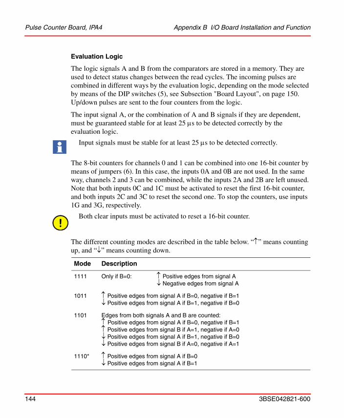
Pulse Counter Board, IPA4 Appendix B I/O Board Installation and Function
144 3BSE042821-600
Evaluation Logic
The logic signals A and B from the comparators are stored in a memory. They are used to detect status changes between the read cycles. The incoming pulses are combined in different ways by the evaluation logic, depending on the mode selected by means of the DIP switches (5), see Subsection "Board Layout", on page 150. Up/down pulses are sent to the four counters from the logic.
The input signal A, or the combination of A and B signals if they are dependent, must be guaranteed stable for at least 25 s to be detected correctly by the evaluation logic.
The 8-bit counters for channels 0 and 1 can be combined into one 16-bit counter by means of jumpers (6). In this case, the inputs 0A and 0B are not used. In the same way, channels 2 and 3 can be combined, while the inputs 2A and 2B are left unused. Note that both inputs 0C and 1C must be activated to reset the first 16-bit counter, and both inputs 2C and 3C to reset the second one. To stop the counters, use inputs 1G and 3G, respectively.
The different counting modes are described in the table below. “” means counting up, and “” means counting down.
Input signals must be stable for at least 25 s to be detected correctly.
Both clear inputs must be activated to reset a 16-bit counter.
Mode Description
1111 Only if B=0: Positive edges from signal A Negative edges from signal A
1011 Positive edges from signal A if B=0, negative if B=1 Positive edges from signal A if B=1, negative if B=0
1101 Edges from both signals A and B are counted:Positive edges from signal A if B=0, negative if B=1 Positive edges from signal B if A=1, negative if A=0 Positive edges from signal A if B=1, negative if B=0 Positive edges from signal B if A=0, negative if A=1
1110* Positive edges from signal A if B=0 Positive edges from signal A if B=1

Appendix B I/O Board Installation and Function Pulse Counter Board, IPA4
3BSE042821-600 145
*Changes in the signals A and B must be separated by at least 25 s in time
When the mode number is set on the DIP switch, “1” means “on”.
Mode settings not specified in the table lead to undefined functions.
Example: An incremental disc encoder has two pulse outputs A and B with a phase shift of 90°. When the direction is changed from forwards to backwards, positive edges are changed to negative, and vice versa. Refer to the illustration on the next page.
0110 Positive edges from signal A irrespective of B
1010 Positive edges from signal A irrespective of B
0010 Positive and negative edges from signal A irrespective of B
1100 Positive and negative edges from signal A irrespective of B
0100* Positive and negative edges from both signals A and B
1000* Positive and negative edges from both signals A and B
0000 Positive edges from signal A irrespective of B Positive edges from signal B irrespective of A
Mode Description
Forwards Backwards
Signal A
Signal B
Mode Direction Pulse counts
1111 Forwards
Backwards
1011 Forwards
Backwards
1101 Forwards
Backwards
1110 Forwards
Backwards
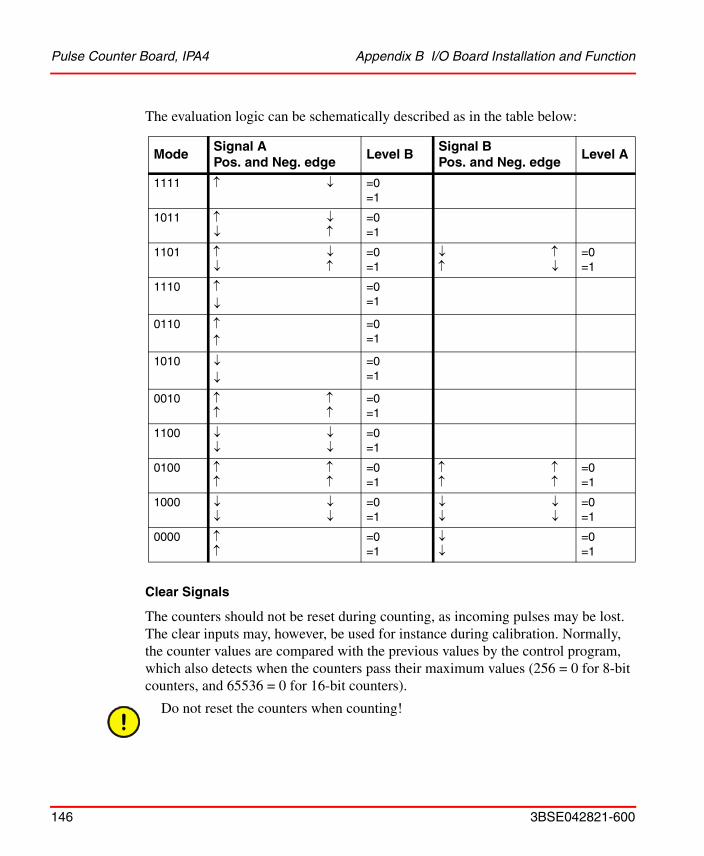
Pulse Counter Board, IPA4 Appendix B I/O Board Installation and Function
146 3BSE042821-600
The evaluation logic can be schematically described as in the table below:
Clear Signals
The counters should not be reset during counting, as incoming pulses may be lost. The clear inputs may, however, be used for instance during calibration. Normally, the counter values are compared with the previous values by the control program, which also detects when the counters pass their maximum values (256 = 0 for 8-bit counters, and 65536 = 0 for 16-bit counters).
ModeSignal APos. and Neg. edge
Level BSignal BPos. and Neg. edge
Level A
1111 =0=1
1011
=0=1
1101
=0=1
=0=1
1110
=0=1
0110
=0=1
1010
=0=1
0010
=0=1
1100
=0=1
0100
=0=1
=0=1
1000
=0=1
=0=1
0000
=0=1
=0=1
Do not reset the counters when counting!

Appendix B I/O Board Installation and Function Pulse Counter Board, IPA4
3BSE042821-600 147
Output Circuits
The counters are addressed from the control system as follows.
IPA4 is provided with a special output memory to separate the counters from the output circuits. The values from all the counters are instantaneously transmitted to the memory every time the first 4 bits of data are to be read. This ensures that the data from a counter refer to the same point in time and that incoming pulses are not lost because of internal data transfer.
Rack Mounting
The IPA4 board fits into any slot intended for I/O boards in a standard rack-based I/O system from ABB Automation. The upper connector (X1) is used for process signals, and the lower one (X2) connects to the standard backplane of the I/O rack. The board is supplied with 12 V DC by the backplane.
Cable Connection
Twisted-pair cable, with individual shielding for each pair of wires, is recommended. Each pair is used for the signal and its inverse (complementary transmitters), or alternatively, for the signal and the common signal ground (non-complementary transmitters). The shield is to be connected at one end, in the shortest possible way, to the chassis of the rack system. Only if high-frequency interference is a problem, may the shield be connected to ground at both ends.
Counter type Input channel No. Address
4 8 bits 0123
00-07 (00 is most significant)10-17 (10 is most significant)20-27 (20 is most significant)30-37 (30 is most significant)
2 16 bits 13
00-17 (00 is most significant)20-37 (20 is most significant)
A spring clamp is enclosed with the board. Use this clamp to connect the signal cable shield to the rack chassis, see "Handling I/O Signal Connections", on page 52.

Pulse Counter Board, IPA4 Appendix B I/O Board Installation and Function
148 3BSE042821-600
The connection of complementary signals, non-complementary signals and unused inputs is shown in the illustration below. Refer also to the Subsection "Input Circuits", on page 142.
Figure 104. Cable connection
Non-complementary transmitter
Unused A and B signals
Out
Out
+
-
Transmitter
Transmitter
Signal
Signal
Inverted signal
Adj refExt ref
Adj refExt ref
Adj ref
Ext ref
Common signal ground
To be connected if an input impedance of 1 k or 90 is desired
Unused G and C signals
Common signal groundGround ref
Adj ref
Ext ref
100
100
100
100
Complementary transmitter

Appendix B I/O Board Installation and Function Pulse Counter Board, IPA4
3BSE042821-600 149
The process signals are connected to the X1 connector through the edge connector at the rear of the rack. The pin layout is shown below.
Connector X1 with pin numbers for the process signals
Channel No.
Row
d
No.
b z
Pin No.
00A 0A 2
0B 0B 4
11A 1A 6
1B 1B 8
22A 2A 10
2B 2B 12
33A 3A 14
3B 3B 16
0 0G 0G 18
1 1G 1G 20
2 2G 2G 22
3 3G 3G 24
0 0C 0C 26
1 1C 1C 28
2 2C 2C 30
3 3C 3C 32
Not
con
nect
ed
Pulse inputs
Gate inputs to stop counting
Reset inputs

Pulse Counter Board, IPA4 Appendix B I/O Board Installation and Function
150 3BSE042821-600
Board Layout
When a new board is installed, the input circuits are adapted to the connected transmitters and the counting mode is specified by means of jumpers and DIP switches. They are located on the board as shown in the illustration below.
Figure 105. Location of jumpers and DIP switches
Adj RefExt Ref GND Ref

Appendix B I/O Board Installation and Function Pulse Counter Board, IPA4
3BSE042821-600 151
Jumpers
The Subsection "Input Circuits", on page 142 provides information about the use of different modes. An overview is given in the table below.
Use Inputs Position
Complementary transmitters and unused inputs*
A,B EXT REF*
Non-complementary transmitters
A,B ADJ REF
Unused inputs* G,C ADJ REF*GND REF*
Complementary transmitters G,C EXT REF
Non-complementary transmitters
G,C ADJ REF
Low impedance* A,B,G,C LOW IMP*
High impedance A,B,G,C
Always EXT* EXT*
8-bit counter* Channels 0,1,2,3
8B*
2
1
3
4
6
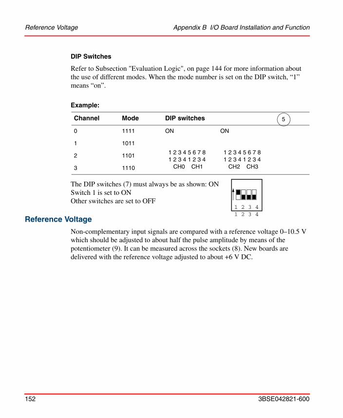
Reference Voltage Appendix B I/O Board Installation and Function
152 3BSE042821-600
DIP Switches
Refer to Subsection "Evaluation Logic", on page 144 for more information about the use of different modes. When the mode number is set on the DIP switch, “1” means “on”.
Example:
The DIP switches (7) must always be as shown: ONSwitch 1 is set to ONOther switches are set to OFF
Reference Voltage
Non-complementary input signals are compared with a reference voltage 0–10.5 V which should be adjusted to about half the pulse amplitude by means of the potentiometer (9). It can be measured across the sockets (8). New boards are delivered with the reference voltage adjusted to about +6 V DC.
Channel Mode DIP switches
0 1111 ON ON
1 2 3 4 5 6 7 8 1 2 3 4 5 6 7 81 2 3 4 1 2 3 4 1 2 3 4 1 2 3 4
CH0 CH1 CH2 CH3
1 1011
2 1101
3 1110
5
1 2 3 41 2 3 4

Appendix B I/O Board Installation and Function Analog Input Board, IBA
3BSE042821-600 153
Analog Input Board, IBAIBA is an analog input board with eight inputs. IBA can either be used on its own, or with associated units, e.g. for galvanic separation (MCVG), differential input (MCV200), temperature measurements (MP, MN) or resistance measurements (MR).
When IBA is used without associated units, the following inputs can be connected: 0–20 mA, 4–20 mA, 0–10 V, 0–5 V and 1–5 V. Each channel is individually selectable.
Features
• Boards can be replaced during operation.
• High flexibility.
• Very high reproducibility.
• High temperature stability.
Indications
There are LEDs on the front panel for individual indication of current signals. Each input which uses the LED input (current) is represented by a LED on the front panel, the intensity of which varies with the value of the input signal. The octal address of each input is shown by the respective LED.
Switch
Normally, the switch on the front panel must be in position “I”. When the board is installed or replaced the switch must be in position “0”.
Jumpers
There are two types of jumpers on the board, one which is changed by moving the jumper or link using pliers or tweezers, and another jumper or strap which is changed by cutting it.
This instruction for jumpers is only valid for CE marked IBA boards.

Analog Input Board, IBA Appendix B I/O Board Installation and Function
154 3BSE042821-600
The movable links are arranged in two directions, see Figure 106, Figure 107 and Figure 108.
The input level (0-5 V, 1-5 V, 0-20 mA and 4-20 mA) (0-10 V) is selected by Sxx1 and current input or voltage input is selected by Sxx2.
xx denotes the channel number, 10 V denotes 0-10 V, C means Current input and V means Voltage input.
Figure 106. The jumpers Sxx1 and Sxx2.
The zero point is selected by Sxx3. 0-20 means 0-20 mA, 0-5 V or 0-l0 V and 4-20 means 4-20 mA or 1-5 V.
Figure 107. The Sxx3 jumpers.
The channels are numbered as follows: 00 - 04 - 10 - 14 - 20 - 24 - 30 - 34.
Sxx1 Sxx2
10V C
V Sxx1
Sxx2
10V
C V
Other input levels Other input
levels
Sxx3
4-20 0-20

Appendix B I/O Board Installation and Function Analog Input Board, IBA
3BSE042821-600 155
Figure 108. IBA shown with protection plate removed. The three groups of jumpers are marked. See strapping examples on next page.
Sockets for IBA modules
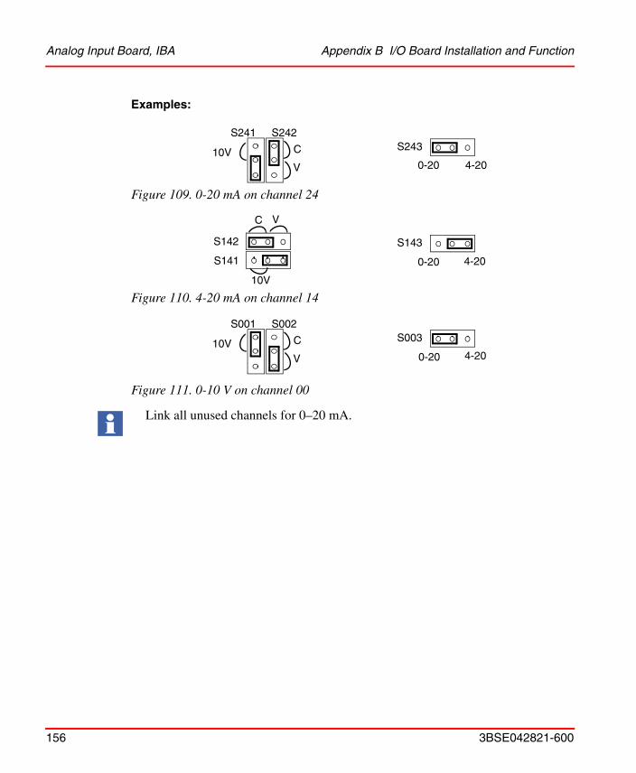
Analog Input Board, IBA Appendix B I/O Board Installation and Function
156 3BSE042821-600
Examples:
Figure 109. 0-20 mA on channel 24
Figure 110. 4-20 mA on channel 14
Figure 111. 0-10 V on channel 00
Link all unused channels for 0–20 mA.
S241 S242
10V C
V
S243
4-20 0-20
S143
4-20 0-20 S141
S142
10V
C V
S001 S002
10V C
V
S003
4-20 0-20
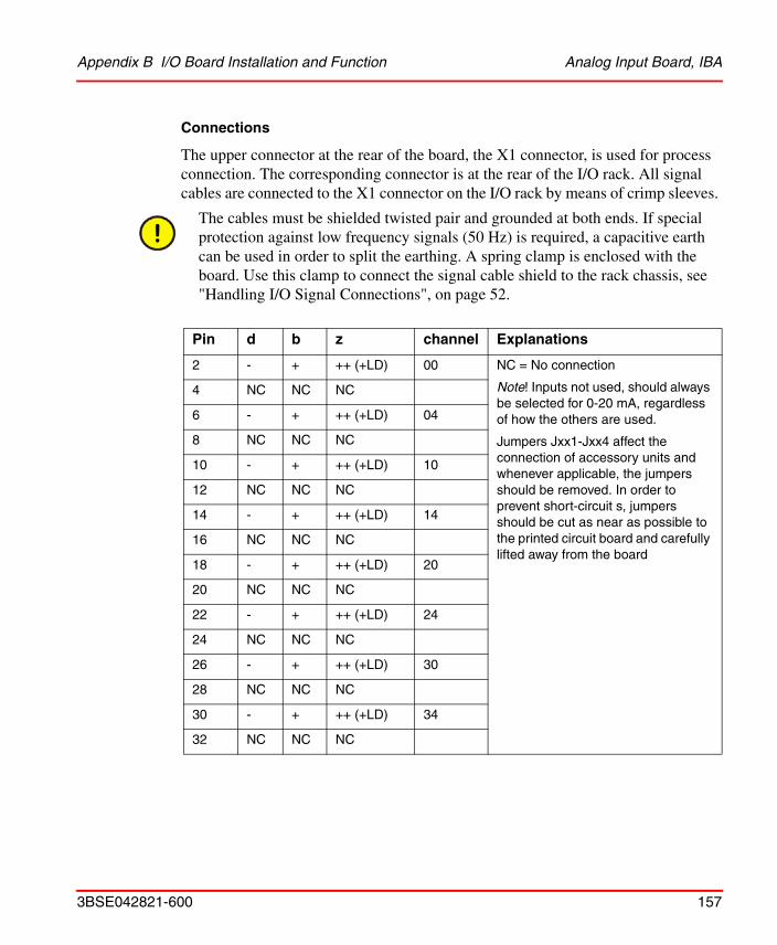
Appendix B I/O Board Installation and Function Analog Input Board, IBA
3BSE042821-600 157
Connections
The upper connector at the rear of the board, the X1 connector, is used for process connection. The corresponding connector is at the rear of the I/O rack. All signal cables are connected to the X1 connector on the I/O rack by means of crimp sleeves.
The cables must be shielded twisted pair and grounded at both ends. If special protection against low frequency signals (50 Hz) is required, a capacitive earth can be used in order to split the earthing. A spring clamp is enclosed with the board. Use this clamp to connect the signal cable shield to the rack chassis, see "Handling I/O Signal Connections", on page 52.
Pin d b z channel Explanations
2 - + ++ (+LD) 00 NC = No connection
Note! Inputs not used, should always be selected for 0-20 mA, regardless of how the others are used.
Jumpers Jxx1-Jxx4 affect the connection of accessory units and whenever applicable, the jumpers should be removed. In order to prevent short-circuit s, jumpers should be cut as near as possible to the printed circuit board and carefully lifted away from the board
4 NC NC NC
6 - + ++ (+LD) 04
8 NC NC NC
10 - + ++ (+LD) 10
12 NC NC NC
14 - + ++ (+LD) 14
16 NC NC NC
18 - + ++ (+LD) 20
20 NC NC NC
22 - + ++ (+LD) 24
24 NC NC NC
26 - + ++ (+LD) 30
28 NC NC NC
30 - + ++ (+LD) 34
32 NC NC NC

Analog Input Board, IBA Appendix B I/O Board Installation and Function
158 3BSE042821-600
Connection of units for high common mode voltage as well as for connection without optional units:
Alternative 1: Connection of four-wire sensor
0-20 mAor4-20 mA
Twisted pair, shielded
Sxx2 set for current (C)
* The positive lead can be connected to two different points, depending on whether or not LED indication is required.
Alternative 2:
Twisted pair, shielded
Connection of two-wire sensor
Sxx2 set for current (C)
24 V unit should always be in the same cabinet as the system.
4-20 mA
* The positive lead can be connected to two different points, depending on whether or not LED indication is required.

Appendix B I/O Board Installation and Function Analog Input Board, IBA
3BSE042821-600 159
Alternative 3:0-5 V or1-5 V
Sxx2 set for voltage (V)Twisted pair, shielded
Connection of voltage sensor, 0–5 V (1–5 V)
Twisted pair, shielded
0-10 V
Alternative 4:
Sxx2 set for voltage (V)Sxx1 set for (10 V)
* The positive lead can be connected to two different points, depending on whether or not LED indication is required.
Connection of voltage sensor, 0–10 V

Modules for IBA Appendix B I/O Board Installation and Function
160 3BSE042821-600
Modules for IBAThe analog input board IBA has several accessory modules. The MCV200 permits large common-mode voltages, the MCVG provides individual electrical separation by transformer, MP and MN are used for temperature measurements and MR for resistance measurements.
MCV200
The MCV200 module is an analog module which permits up to 200 V DC common-mode voltage for each channel. It also adds the ± 5 V range.
MCVG
The MCVG module is an analog module which permits a maximum common mode voltage of 750 V DC per channel.
MP
The MP module measures temperatures with a Pt100 sensor (DIN 43760, =0.00385). MP is linearized. There are six modules giving a total temperature range from -30oC to +600oC. See "Modules MP, MN and MR", on page 196.
MN
The MN module measures temperatures with a Ni1000 sensor. MN is not linearized:1000 ohm at 0 oC, 871.7ohmat -30oC and 1390.1 ohm at 80oC.
MR
The MR module measures resistance and is used for position sensing, pressure measurements, etc. There are three modules giving a total range from 100 ohm to 1000 ohm.

Appendix B I/O Board Installation and Function Installation of MCV200
3BSE042821-600 161
Installation of MCV200
On installation of an MCV200 module the JXX3 and JXX4 jumpers on the IBA board must be cut (refer to the IBA description). The JXX1 and JXX2 jumpers remain intact.
The signal type is selected both on the IBA board (refer to the IBA description) and on the MCV200 module:
Settings of S3 and S4 Jumpers on MCV200
Figure 112. Note that the 0-10 V setting on the IBA is not used.
When the signal type has been selected, the MCV200 module can be inserted at the IBA board connectors marked xXX1 and xXX2, component side to component side.
Interconnections are made according to alternatives 1, 2 or 3 in the IBA description.
Figure 113. Locations of jumpers S3 and S4 on the MCV200.
For input signals of 0-10 V, IBA is jumpered for 0-5 V
For input signals of 0-5 V, 1-5 V, 4-20 mA, IBA is jumpered for selected input signal.
For input signals of ±5 V or ±20 mA, IBA is jumpered for 0-5 V respective 0-20 mA
S4
±5V
+5V
S3
S4
±5V
+5V
S3
S4
±5V
+5V
S3
S3S4
+5V±5V

Installation of MCVG Appendix B I/O Board Installation and Function
162 3BSE042821-600
Installation of MCVG
On installation of an MCVG module, the JXX3 and JXX4 jumpers on the IBA board must be cut (refer the IBA description).
The maximum common mode voltage may be selected as either 250 V DC or 750 V DC. If 250 V DC is selected, inputs with or without LEDs may be used. The LED inputs may not be used with 750 V DC common mode voltage. Jumpers JXX1 and JXX2 must, in this case, also be cut.
Once this is done, the MCVG can be inserted into the IBA board at the connectors marked xXX1 and xXX2, component side to component side.
Refer to the IBA description for selection of signal type.
Interconnections are made according to alternatives 1, 2, 3 or 4 in the IBA description.
Installation of the MP, MR and MN Modules
1. Remove the IBA board insulation plate.
Figure 114. Removing the insulation plate.
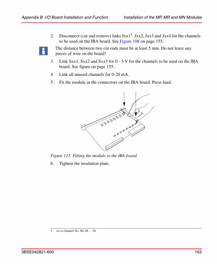
Appendix B I/O Board Installation and Function Installation of the MP, MR and MN Modules
3BSE042821-600 163
2. Disconnect (cut and remove) links Jxx11, Jxx2, Jxx3 and Jxx4 for the channels to be used on the IBA board. See Figure 108 on page 155.
3. Link Sxx1, Sxx2 and Sxx3 for 0 - 5 V for the channels to be used on the IBA board. See figure on page 155.
4. Link all unused channels for 0-20 mA.
5. Fit the module in the connectors on the IBA board. Press hard.
Figure 115. Fitting the module to the IBA board.
6. Tighten the insulation plate.
1. xx is channel No. 00, 04 …34.
The distance between two cut ends must be at least 5 mm. Do not leave any pieces of wire on the board!

Installation of the MP, MR and MN Modules Appendix B I/O Board Installation and Function
164 3BSE042821-600
Connection of Modules for Temperature or Resistance Measurements
Figure 116. Connecting a temperature or resistance transmitter.Note. Max 50cable resistance. All three wires must have the same resistance.
For modules without connected transmitter, the compensation current (marked + in the IBA description), should always be connected to 0 V. In other cases the current consumption rises approximately 10 mA each module and then it is not possible to have a full rack with IBA.
Transmitter
Test
currentCompensation

Appendix B I/O Board Installation and Function Analog Output Board, OCAHG
3BSE042821-600 165
Analog Output Board, OCAHGOCAHG is an analog output board for current signals of 0–20 or 4–20 mA and voltage signals of 0–10 V. The outputs are as a group of four, separated from the I/O bus by optocouplers. They are numbered 00, 10, 20 and 30. Outputs of 0–20 or 4–20 mA are selected by straps on the board. The resolution is 8 bits.
OCAHG generates analog signals to control devices, instruments, etc. By means of the signals DDC1 and MAN, control can either be automatic (from the control system) or manual via the INCREASE/DECREASE inputs. See figure "Example of manual control connection.", on page 169.
OCAHG retains its output values in the event of a CPU failure.
Switch
Normally, the switch on the front panel should be in position “I”. When the board is installed or replaced the switch must be in position “0”.
Note: If the board is operating and analog signals are transmitted and the switch is placed in position “0”, it should remain there for 2-3 seconds before switching over to position “I” (to clear the internal analog filter).
1. DDC = Direct Digital Control

Analog Output Board, OCAHG Appendix B I/O Board Installation and Function
166 3BSE042821-600
Jumpers
There are 4 jumpers on the board, one for each output (00, 10, 20 and 30), for selection of 0-20 mA or 4-20 mA.
Figure 117. Jumpers on OCAHG.
Connections
The upper connector at the rear of the board, the X1 connector, is used for process connection. The corresponding connector is at the rear of the I/O rack. All signal cables are connected to the X1 connector on the I/O rack by means of crimp sleeves.
Each analog output signal must be connected to the system with both signal and return leads. The two leads must be run together throughout their entire length.
Installation Notes
• The cables must be shielded twisted pair cables grounded at both ends. If special protection against low-frequency signals (50 Hz) is required, a capacitive earth can be used in order to split up the earthing.
• A spring clamp is enclosed with the board. Use this clamp to connect the signal cable shield to the rack chassis, see "Handling I/O Signal Connections", on page 52.
00102030
0-20 mA
4-20 mA

Appendix B I/O Board Installation and Function Analog Output Board, OCAHG
3BSE042821-600 167
The connections +24 V and DDC (see table below) must be strapped if the manual operation facility is not used or if the channel is not used at all.
24 V and 0 V are internally connected between the channels.
Strap +24 V and DDC if the manual operation facility is not used or if the channel is not used at all.
Channel d b z Pin
Output designation
00
MAN DDC +24 V 2
MAN Mode DDC Mode 4
INCREASE DECREASE 0-20 mA or 4-20 mA
6
0-10 V 0 V +24 V 8
10
MAN DDC +24 V 10
MAN Mode DDC Mode 12
INCREASE DECREASE 0-20 mA or 4-20 mA
14
0-10 V 0 V +24 V 16
20
MAN DDC +24 V 18
MAN Mode DDC Mode 20
INCREASE DECREASE 0-20 mA or 4-20 mA
22
0-10 V 0 V 0 V 24
30
MAN DDC +24 V 26
MAN Mode DDC Mode 28
INCREASE DECREASE 0-20 mA or 4-20 mA
30
0-10 V 0 V 0 V 32

Analog Output Board, OCAHG Appendix B I/O Board Installation and Function
168 3BSE042821-600
Description
The input signals MAN, DDC, INCREASE and DECREASE can be controlled from a hand module, or a push-button set that connects to the OCAHG board according to connection instructions overleaf. It is also possible to control the board from digital outputs, e.g. from a digital output board.
When connecting a hand module or a push-button set, the signal cable is to be shielded and the shield connected to the earth bar in the system cabinet near the OCAHG board’s X1 connector. 0V for each output should be connected to a common signal ground with the shortest lead possible.
MAN mode is obtained when MAN = 1 and DDC = 0. The DDC mode is obtained when MAN = 0 and DDC = 1. Control of the analog output (in MAN mode) is accomplished with the INCREASE and DECREASE inputs.
In MAN mode, each output can still be controlled, in the event of a power failure, if the board is powered from an external 24 V DC source. When switching from DDC to MAN, the output signals remain at the last value set in DDC mode.
At power up, the board is automatically placed in MAN mode and the outputs are zeroed (output signal 4 mA or 0 mA).
In MAN mode, it takes approximately 20 seconds to drive an output from 0 to 100%. The 0–10 V output follows the current output and can be used for indication purposes.
If the 24 V DC supply is switched off, let it remain off for at least 2–3 seconds before you switch it on again, or else the output value may be erroneous. If this is not acceptable, use a UPS if necessary.
The digital inputs MAN, DDC, INCREASE and DECREASE have filters on their inputs. The time taken to activate an input is 200 ms.

Appendix B I/O Board Installation and Function Analog Output Board, OCAHG
3BSE042821-600 169
Figure 118. Block diagram of OCAHG.
Figure 119. Example of manual control connection.
Controllogic
Loadable counter
D/Aconverter
Watch-dog
Board contact X1DesignationDDCMANINCREASEDECREASEDDC ModeMAN Mode+24V
4-20 mA(0-20 mA)
0V
0-10V
Optocouplers
Buscontrolsystem
Optocouplers
2.2 K 1/2 W
2.2 K 1/2 W
+24 V
DDC Mode
DDC
INCREASE
DECREASE
MAN Mode
MAN

Analog Output Board, OCVA Appendix B I/O Board Installation and Function
170 3BSE042821-600
Analog Output Board, OCVAOCVA is an analog output board with two channels for current signals of 0–20 mA or 4–20mA and voltage signals of ±10 V or 0–10 V. The various ranges are selected using connections in the process connector.
Features
• The analog circuits of OCVA are electrically separated by optocouplers from the digital control logic and the control system. The channels are not galvanically separated from each other.
• OCVA can be set up so that the outputs either go to zero or remain at the selected safety values during CPU shutdown.
• OCVA has 12-bit resolution for the ±10 V ranges and 11-bit resolution for the other current and voltage ranges.
Switch
Normally, the switch on the front panel should be in position “I”. When the board is installed or replaced the switch must be in position “0”.

Appendix B I/O Board Installation and Function Analog Output Board, OCVA
3BSE042821-600 171
Connections
The upper connector at the rear of the board, the X1 connector, is used for process connection. The corresponding connector is at the rear of the I/O rack. All signal cables are connected to the X1 connector on the I/O rack by means of crimp sleeves.
Table 15. Connector X1 pin assignment OCVA
Channel d b z Pin
00
Current range select (+24V) 2Voltage range select Current range select 4
Voltage range select Current output 6Voltage output Current GND (+24V) 8
(+24V) 10Voltage GND 12
14(0V) (+24V) 16
20
Current range select (+24V) 18Voltage range select Current range select 20
Voltage range select Current output 22Voltage output Current GND (0V) 24
(+24V) 26Voltage GND 28Stop selection Stop selection 30
(0V) (0V) 32
The cables must be shielded twisted pair and grounded at both ends. If special protection against low frequency signals (50 Hz) is required, a capacitive earth can be used in order to split the earthing. A spring clamp is enclosed with the board. Use this clamp to connect the signal cable shield to the rack chassis, see "Handling I/O Signal Connections", on page 52.

Analog Output Board, OCVA Appendix B I/O Board Installation and Function
172 3BSE042821-600
Ground Reference
0 V DC for the outputs and supply must be referenced to ground, either directly or through a bipolar capacitor of 0.01 µF ±20% and with a voltage rating above the potential difference between 0 V DC and ground (use e.g. Phoenix TT-SLKK 5-C 12n 230AC). This is to meet the specified interference standard.
Description
Each channel can supply both current and voltage output signals at the same time. When using a current output the corresponding voltage range must be set to 0-10 V.
The output signal is controlled by writing to the appropriate channel memory word (00 or 20 respectively).
Since the bit resolution is less than a 16-bit memory word, only the most significant bits of a word are used for digital-to-analog conversion.
The voltage range is selected by connecting or leaving open two “Voltage select” terminals in the process connector. If the terminals are linked, a ±10 V signal is produced, otherwise the range is 0-10 V.
Selection of the minimum current is performed in a similar manner using the two “Current select” terminals in the process connector. If the terminals are linked, a 0–20 mA signal is produced, otherwise the range is 4-20 mA. In a similar manner, “Zero output” or “Hold the present output” during CPU shutdown can be selected.
The required setting is selected by connecting or leaving open the “Stop selection” terminals in the process connector. If the terminals are linked the outputs go to 0 V/0 mA during CPU shutdown, irrespective of the other settings. If the terminals are not connected the levels of the outputs are maintained during CPU shutdown.

Appendix B I/O Board Installation and Function Analog Output Board, OCVA
3BSE042821-600 173
Figure 120. OCVA block diagram.
Installation Instructions
The selection link connections to the board must be as short as possible, and definitely not more than 15 cm.
Each analog output signal must be connected to the system with both signal and return leads. The two leads must be run together throughout their entire length.
I/O bus
Bus
inte
rfac
eC
ontr
ol lo
gic
Reg
iste
r
Opt
o co
uple
rs
D/A converter
Voltage to currentconverter
Range selection logic
DC/DC
Voltage to current converter
D/A converter
Process connectorOCV Process
Voltage channel 00
Voltage GND
Load
Voltage GND
Current channel 00 Load
Current GNDRange
Current channel 20
Current GND
Load
Load
External powersupply
24 VDC
Voltage channel 20
Filter

Test and Simulation Equipment, PTC and IVAPOT Appendix B I/O Board Installation and Function
174 3BSE042821-600
The return lead for the current signal is connected to “Current GND” and the return lead for the voltage signal to “Voltage GND” in the process connector. “Current GND” and “Voltage GND” connections are provided for each channel (see connection instructions).
To maintain board accuracy, the “Current GND” and “Voltage GND” terminals must not be connected to any other terminals. The return lead must only be connected.
The supply voltage for the OCVA card is 24 V which is connected to the +24 V and 0 V terminals on the process connector. To obtain the best tolerance of wire-borne interference the +24 V is connected to Z26 and the 0V to Z32. All +24 V terminals are connected together on the board and all 0 V terminals are also connected together.
When the 24 VDC supply is switched on, all outputs adopt levels 0 V/0 mA, irrespective of the board selections. These values are maintained until a new value is written to the board. This also applies if the switch on the front is changed from “0” to “I”.
Test and Simulation Equipment, PTC and IVAPOTTwo boards are available for test and simulation. They are used to facilitate starting up, testing and troubleshooting the system.
• PTCDigital simulation board. A panel with 32 switches to simulate inputs is connected to the board. The board must be placed in a digital input board location.
• IVAPOTAnalog simulation board. 8 potentiometers for simulation of analog inputs are mounted on the front of the board. The board must be placed in an analog input board location.
A filter is required for the +24 V supply.
These two boards do not meet the EMC directive 89/336/EEC.

3BSE042821-600 175
Appendix C Technical Specifications
This appendix contains technical specifications of CI865 on page 175, ControlNet on page 177 and I/O Systems - Rack I/O on page 185. For information about technical specifications of Series 200 I/O see I/O Systems - Series 200 I/O on page 201 for references to relevant manuals.
CI865
Table 16. CI865 Interface Specifications
Item Value
Type Satt I/O Communication Interface
Galvanic isolation Yes
Status indicators Run normally green, FAIL exceptionally red,
COM A/COM B
Connector BNC
Current consumption
(from CEX-Bus 24 V DC)
120 mA typical (200 mA max.)
Power dissipation 2.9 W typical
Capacity Max 5 I/O racks with 20 I/O units each
Protection Rating IP20 according to EN60529, IEC 529

CI865 Appendix C Technical Specifications
176 3BSE042821-600
Please refer to the manual AC 800M Controller Hardware, Hardware and Operation (3BSE036351Rxxxx) for more information about technical specifications of the CI865.
Weight 700 g (1.5 lb) (package CI865K01 with CI865 and TP865)
Dimensions W 59 x H 185 x D 127.5 mm
(W 2.9 x H 7.3 x D 5.0 in)
Table 16. CI865 Interface Specifications (Continued)
Item Value
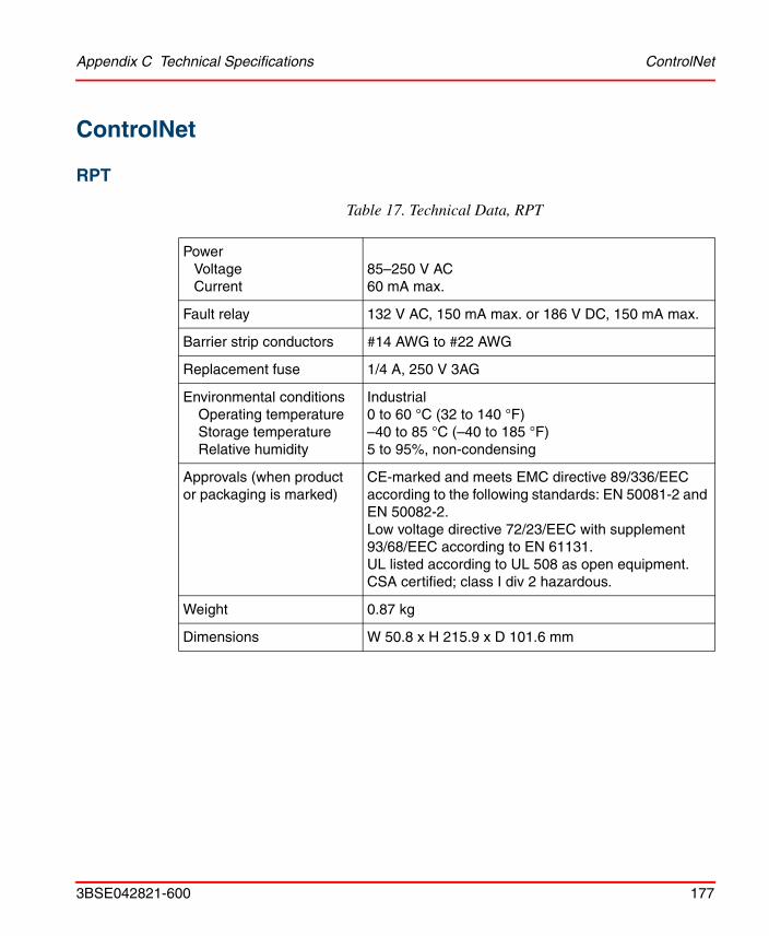
Appendix C Technical Specifications ControlNet
3BSE042821-600 177
ControlNet
RPT
Table 17. Technical Data, RPT
Power VoltageCurrent
85–250 V AC60 mA max.
Fault relay 132 V AC, 150 mA max. or 186 V DC, 150 mA max.
Barrier strip conductors #14 AWG to #22 AWG
Replacement fuse 1/4 A, 250 V 3AG
Environmental conditionsOperating temperatureStorage temperatureRelative humidity
Industrial0 to 60 °C (32 to 140 °F)–40 to 85 °C (–40 to 185 °F)5 to 95%, non-condensing
Approvals (when product or packaging is marked)
CE-marked and meets EMC directive 89/336/EEC according to the following standards: EN 50081-2 and EN 50082-2.Low voltage directive 72/23/EEC with supplement 93/68/EEC according to EN 61131.UL listed according to UL 508 as open equipment.CSA certified; class I div 2 hazardous.
Weight 0.87 kg
Dimensions W 50.8 x H 215.9 x D 101.6 mm

RPTD Appendix C Technical Specifications
178 3BSE042821-600
RPTD
Table 18. Technical Data, RPTD
Power VoltageCurrent
20–72 V DC100 mA max.
Fault relay 132 V AC, 150 mA max. or 186 V DC, 150 mA max.
Barrier strip conductors #14 AWG to #22 AWG
Replacement fuse 2 A, 250 V (slow blow)
Environmental conditionsOperating temperatureStorage temperatureRelative humidity
Industrial0 to 60 °C (32 to 140 °F)–40 to 85 °C (–40 to 185 °F)5 to 95%, non-condensing
Approvals (when product or packaging is marked)
CE-marked and meets EMC directive 89/336/EEC according to the following standards: EN 50081-2 and EN 50082-2.UL listed according to UL 508 as open equipment.CSA certified; class I div 2 hazardous.
Weight 0.82 kg
Dimensions W 50.8 x H 215.9 x D 101.6 mm

Appendix C Technical Specifications RPA
3BSE042821-600 179
RPA
Table 19. Technical Data, RPA
Power supplyNominal input voltageInput voltage rangeCurrent
Backplane output currentWire size
24 V DC18.0–36.0 V DCMax. 700 mA at 24 V DC based on worst case module loadingMax. 1.6 A at 5 V DC12–28 AWG
Communication rate 5 Mbit/s
Environmental conditionsOperating temperatureStorage temperatureRelative humidityShock Operating
Non-operatingVibration
Industrial0 to 60 °C (32 to 140 °F)–40 to 85 °C (–40 to 185 °F)5 to 95%, non-condensing30 g peak acceleration, 11±1 ms pulse width50 g peak acceleration, 11±1 ms pulse widthTested 5 g at 10–500 Hz per IEC 68-2-6
Approvals (when product or packaging is marked)
CE-marked and meets EMC directive 89/336/EEC according to the following standards: EN 50081-2 and EN 50082-2.UL listed according to UL 508 as open equipment.CSA certified; class I div 2 hazardous.
Weight 0.23 kg
Dimensions W 99 x H 96 x D 69.0 mm
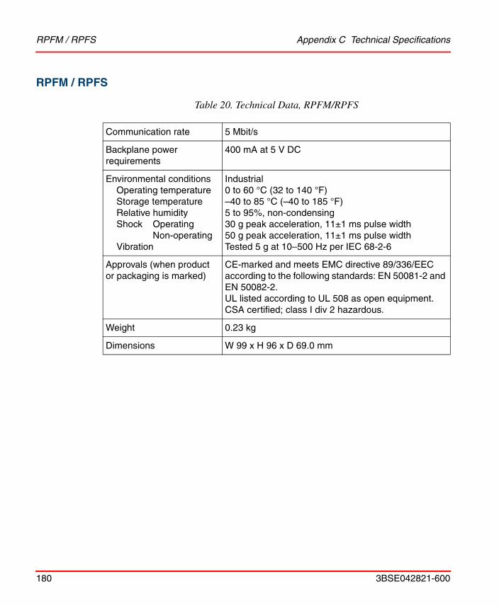
RPFM / RPFS Appendix C Technical Specifications
180 3BSE042821-600
RPFM / RPFS
Table 20. Technical Data, RPFM/RPFS
Communication rate 5 Mbit/s
Backplane power requirements
400 mA at 5 V DC
Environmental conditionsOperating temperatureStorage temperatureRelative humidityShock Operating
Non-operatingVibration
Industrial0 to 60 °C (32 to 140 °F)–40 to 85 °C (–40 to 185 °F)5 to 95%, non-condensing30 g peak acceleration, 11±1 ms pulse width50 g peak acceleration, 11±1 ms pulse widthTested 5 g at 10–500 Hz per IEC 68-2-6
Approvals (when product or packaging is marked)
CE-marked and meets EMC directive 89/336/EEC according to the following standards: EN 50081-2 and EN 50082-2.UL listed according to UL 508 as open equipment.CSA certified; class I div 2 hazardous.
Weight 0.23 kg
Dimensions W 99 x H 96 x D 69.0 mm

Appendix C Technical Specifications Mounting Dimensions
3BSE042821-600 181
Mounting Dimensions
Use the mounting dimensions to help you mount your taps and universal mounting brackets. Make copies of these templates as necessary to help you mark placement for these components. All measurements in millimeters.
Taps
Figure 121. Mounting Dimensions, T-tap

Mounting Dimensions Appendix C Technical Specifications
182 3BSE042821-600
Figure 122. Mounting Dimensions, Y-tap
Universal Mounting Bracket
Figure 123. Mounting Dimensions, Universal Mounting Bracket

Appendix C Technical Specifications Mounting Dimensions
3BSE042821-600 183
Coax Repeaters
Figure 124. Mounting Dimensions, Coax Repeaters

Mounting Dimensions Appendix C Technical Specifications
184 3BSE042821-600
Fiber Repeater and Fiber Module
Figure 125. Mounting Dimensions, Fiber Repeater and Fiber Module
69
96
99
All sizes in mm

Appendix C Technical Specifications I/O Systems - Rack I/O
3BSE042821-600 185
I/O Systems - Rack I/O
General Technical Specifications
Function Data
Temperature Operating: +5-55°C (max. mean temp. over 24 hours is 50°C)
Non-operating: -25- +70°C
Humidity Max 90%, non-condensing
Protection class IP20
Design standard Fulfils the EMC directive 89/336/EEC for industrial environment and the low voltage directive, LVD, 73/23/EEG with supplement 93/68/EEG
Continuous working voltage Combination of application nominal signal voltage and common mode voltage relative to system logic ground reference.
Isolation test voltage Isolation withstand voltage verified by design measurement of clearance and creepage distances or by specified high-voltage type test and/or production test.For low-level I/O voltage (max 50 V AC/ 75 V DC), the corresponding test voltage is 350 V AC/500 V DC for one minute. For higher level I/O voltage (> 50 V AC/ 75 V DC), the test voltage is 1000 V AC + 2xUe (=1000+2x250=1500 V AC at 250 V AC signal voltage) for one minute. The one-minute test may be replaced by a one second test using 20% higher test voltage or any other compatible test method.
Rated current for crimp sleeves
5 A
Board type Double-sized Euro board

Rack Adapter Board, 200-RACN Appendix C Technical Specifications
186 3BSE042821-600
Rack Adapter Board, 200-RACN
Function Data
Number of channels 1
Communication protocol ControlNet
Access method CTDMA (Concurrent Time Division Multiple Access)
Serial interface Separation via a signal transformer
Speed of transfer 5 Mbit/s
Status indicators Green/Red LED for board status (OK)Red LED for I/O copy informationGreen/Red LED for communication information (COM A and B)Power LED
Power supply From Power supply unit PSF
Internal current consumption (from PSF)
200-RACN200-RACN/A
400 mA/+5V; max. 100mA/+12V600 mA/+5V; max. 100mA/+12V
ControlNet connector BNC 75 ohm
Dimensions H 262 x W 60 x D 190 mm
Order codes 200-RACN200-RACN/A
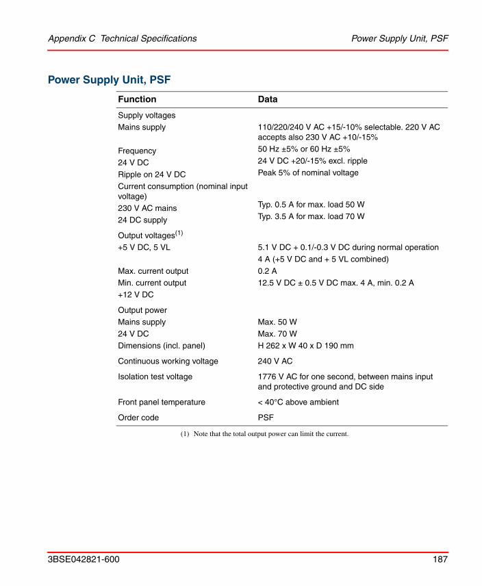
Appendix C Technical Specifications Power Supply Unit, PSF
3BSE042821-600 187
Power Supply Unit, PSF
Function Data
Supply voltagesMains supply
Frequency24 V DC
Ripple on 24 V DC
Current consumption (nominal input voltage)
230 V AC mains24 DC supply
110/220/240 V AC +15/-10% selectable. 220 V AC accepts also 230 V AC +10/-15%50 Hz ±5% or 60 Hz ±5%
24 V DC +20/-15% excl. ripple
Peak 5% of nominal voltage
Typ. 0.5 A for max. load 50 W
Typ. 3.5 A for max. load 70 W
Output voltages(1)
+5 V DC, 5 VL
Max. current outputMin. current output
+12 V DC
(1) Note that the total output power can limit the current.
5.1 V DC + 0.1/-0.3 V DC during normal operation
4 A (+5 V DC and + 5 VL combined)
0.2 A12.5 V DC ± 0.5 V DC max. 4 A, min. 0.2 A
Output power
Mains supply
24 V DCDimensions (incl. panel)
Max. 50 W
Max. 70 WH 262 x W 40 x D 190 mm
Continuous working voltage 240 V AC
Isolation test voltage 1776 V AC for one second, between mains input and protective ground and DC side
Front panel temperature < 40°C above ambient
Order code PSF
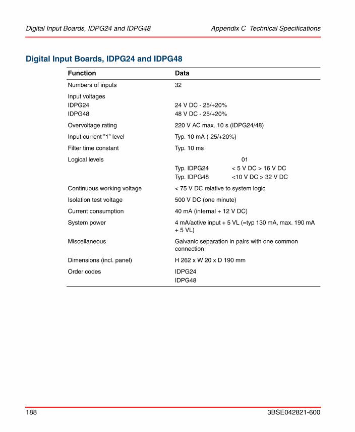
Digital Input Boards, IDPG24 and IDPG48 Appendix C Technical Specifications
188 3BSE042821-600
Digital Input Boards, IDPG24 and IDPG48
Function Data
Numbers of inputs 32
Input voltages
IDPG24IDPG48
24 V DC - 25/+20%48 V DC - 25/+20%
Overvoltage rating 220 V AC max. 10 s (IDPG24/48)
Input current ”1” level Typ. 10 mA (-25/+20%)
Filter time constant Typ. 10 ms
Logical levels 01Typ. IDPG24 < 5 V DC > 16 V DC
Typ. IDPG48 <10 V DC > 32 V DC
Continuous working voltage < 75 V DC relative to system logic
Isolation test voltage 500 V DC (one minute)
Current consumption 40 mA (internal + 12 V DC)
System power 4 mA/active input + 5 VL (=typ 130 mA, max. 190 mA + 5 VL)
Miscellaneous Galvanic separation in pairs with one common connection
Dimensions (incl. panel) H 262 x W 20 x D 190 mm
Order codes IDPG24
IDPG48

Appendix C Technical Specifications Digital Input Boards, IAPG230
3BSE042821-600 189
Digital Input Boards, IAPG230
Function Data
Number of inputs 16 optocoupled
Input voltage 230 V AC -15%/ +10%
Overvoltage rating 500 V AC max. 10 s
Input current for activated input (typically 10 mA)
6.5-14 mA at 230 V AC -15%/+10%47-63 Hz
Frequency range 47-63 Hz
Filter time constant Typ. 20 ms
Logical levels 0 1
Typ. < 70 V > 130 V
Continuous working voltage 230 V AC
Isolation test voltage 1752 V AC for 1 second, between inputs and between any input and system logic or front panel
Current consumption 20 mA (internal + 12 V DC)
System power 5-15 mA/active input + 5 VL (typ. 160 mA, tot. max. 80-240 mA)
Dimensions (incl. panel) H 262 x W 20 x D 190 mm
Order code IAPG230

Digital Output Board, ODPG.8 Appendix C Technical Specifications
190 3BSE042821-600
Digital Output Board, ODPG.8
Function Data
Number of outputs 32 optocoupled
Number of separate groups 4
Supply voltage (external) 10-60 V DC
The groups can have common or separate supplies
Peak voltage 75 V DC (mean value, max. 60 V DC as above)
Load current Max. 0.8 A per outputMax. 3.2 A per group
Max 8 A per board
Surge current Max. 2 A for 50 ms
Leakage current Max. 2 mA, typically < 0.5 mA
Recommended external fuses 3.2 A fast-blow for each group
Voltage drop, output Max 2.5 V DC, typically <1 V DC
Activation time Max 10 µs, typically 5 µs
Deactivation time Max. 400 µs, typically 200 µs
Continuous working voltage < 75 V DC relative to system ground
Isolation test voltage 500 V DC for one minute, between input groups and between each group and system logic
Current consumption 30 mA (internal +12 V DC) 2-7 mA/active output (+5 VL) Tot max. 60-230 mA, typ. 140 mA
Dimensions (incl. panel) H 262 x W 20 x D 190 mm
Order code ODPG.8
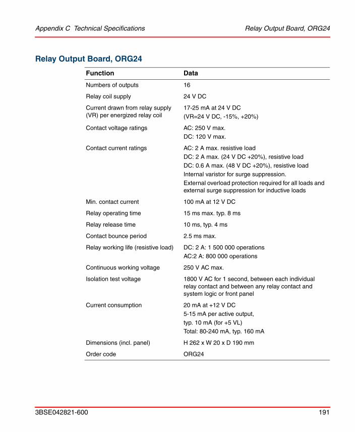
Appendix C Technical Specifications Relay Output Board, ORG24
3BSE042821-600 191
Relay Output Board, ORG24
Function Data
Numbers of outputs 16
Relay coil supply 24 V DC
Current drawn from relay supply (VR) per energized relay coil
17-25 mA at 24 V DC
(VR=24 V DC, -15%, +20%)
Contact voltage ratings AC: 250 V max.
DC: 120 V max.
Contact current ratings AC: 2 A max. resistive load
DC: 2 A max. (24 V DC +20%), resistive load
DC: 0.6 A max. (48 V DC +20%), resistive loadInternal varistor for surge suppression.
External overload protection required for all loads and external surge suppression for inductive loads
Min. contact current 100 mA at 12 V DC
Relay operating time 15 ms max. typ. 8 ms
Relay release time 10 ms, typ. 4 ms
Contact bounce period 2.5 ms max.
Relay working life (resistive load) DC: 2 A: 1 500 000 operations
AC:2 A: 800 000 operations
Continuous working voltage 250 V AC max.
Isolation test voltage 1800 V AC for 1 second, between each individual relay contact and between any relay contact and system logic or front panel
Current consumption 20 mA at +12 V DC
5-15 mA per active output,
typ. 10 mA (for +5 VL)Total: 80-240 mA, typ. 160 mA
Dimensions (incl. panel) H 262 x W 20 x D 190 mm
Order code ORG24

Digital Output Board, Short-circuit-proof, ODSG Appendix C Technical Specifications
192 3BSE042821-600
Digital Output Board, Short-circuit-proof, ODSG
Function Data
Number of outputs 32 optocoupled and 2 optocoupled error bistables
Number of inputs 2 optocoupled 24 V DC
10 mA reset signals
External supply voltage 19-30 V DC
Voltage limit 50 V DC max. for 1 min. (25°C)
Load current 0.8 A per output max.16 A per board max.
Short circuit current Typ. 4 A, max. 10 A, fuse trip delay ð20 ms (25°C)
Leakage current Max. 100 µA, typ. 10 µA. Typical value for a short circuited output is 10 mA
External fuse 16 A per board (slow fuse)
Resistance Typ. 0.4 , max. 0.6 at 0.5 A.Typ. 0.6 , at 0.8 A (25°C)
Rise time Typ. 10 µs
Fall time Typ. 150 µs
Current consumption
System (12 V DC)
LED (5 VL)
40 mA
7 mA per active output, typ. 140 mA
Continuous working voltage < 75 V DC relative to system ground
Isolation test voltage 500 V DC for one minute, between I/O and system logic
Dimensions (incl. panel) H 262 x W 20 x D 190 mm
Order code ODSG

Appendix C Technical Specifications Pulse Counter Board, IPA4
3BSE042821-600 193
Pulse Counter Board, IPA4
Function Data
Number of inputs 4 (with 8-bit counter)
2 (with 16-bit counter)
Galvanic separation No
Input impedance 1 k or about 90
Power dissipation 0.25 W max. across connected terminating resistor
Max. pulse amplitude, complementary inputs
33 V DC (1 k input impedance) or
10 V DC (90 impedance)
Max. pulse amplitude, non-complementary inputs
24 V DC
Input voltage difference 1 V DC min. rel. inverted input or rel. transition level
Max pulse frequency 10 kHz
Process cabling Twisted-pair cable with individual shielding for each pair of wires
Current consumption 150 mA,12 V DC (1.8 W)
Reference voltage level 0-10.5 V DC, adjustable
Dimensions (incl. panel) H 262 x W 20 x D 190 mm
Order code IPA4

Analog Input Board, IBA Appendix C Technical Specifications
194 3BSE042821-600
Analog Input Board, IBA
Function Data
Number of inputs 8
Input impedance
Current
Voltage
250 without LED
300 k
Voltage drop 5 V DC max. without LED
8 V max. with LED
Accuracy ±0.2% FS at 25°C
Temperature stability ±0.002% FS/°C
Max. permanent permissible overloadCurrent
Voltage
30 mA
30 V DC
Input type Single-ended common earth
Input filter (time to 63% of FS) 70 ms ± 10% filter of first order Breaking point at about 2.3 Hz
Input connector Harting, crimp pin
Crosstalk between channels 79 dB attenuation
Non-linearity 0.02% FS
Repeating accuracy 0.001% FS
RFI immunity Error of less than 0.8% of FS at 10 V/m, 27-1000 MHz
Current consumption 90 mA (12 V DC) typ. for the board. When modules are used, the current consumption increases
Dimensions (incl. panel) H 262 x W 20 x D 190 mm
Order code IBA

Appendix C Technical Specifications Analog Input Board, IBA
3BSE042821-600 195
Module MCV200
Module MCVG
Function Data
Common mode suppression 72 dB attenuation with 0-10 V ± 5 V DC, otherwise 66 dB
Continuous working voltage < 75 V DC relative to system ground
Common mode voltage relative to ground
Max. 200 V DC (by design)
Impedance:Common modeDifferential mode
400 k800 k
Temperature stability Max. ± 0.003% FS / °C
Current consumption 12 V DC: + 4 mA per module
Miscellaneous All other technical data are the same as for IBA
Dimensions H 107 x W 18 x D 13 mm
Order code MCV200
Function Data
Continuous working voltage < 75 V DC relative to system ground
Common mode voltage relative to ground
750 V DC without LED (by design)250 VDC with LED (by design)
Common mode suppression 94 dB attenuation
Leakage current 220 V, 50 Hz, 2 µA typ.
Accuracy ±0.3% FS at 25°C
Temperature stability Max. ±0.002% FS/°C
Non-linearity Max. 0.1% FS
Current consumption 12 V DC: 18 mA per module

Analog Input Board, IBA Appendix C Technical Specifications
196 3BSE042821-600
Modules MP, MN and MR
Miscellaneous All other technical data are the same as for IBA.
Dimensions H 107 x W 18 x D 13 mm
Order code MCVG
Function Data
Input impedance Min. 10 M
Accuracy at 25°C
MP100-MP400
MP600
MN80
MR100-MR1000
±0.4% FS, DIN 43760, =0.00385
±0.6% FS, DIN 43760, =0.00385
Follows the curve shown below, ±0.4% FS
±0.5% FS
Temperature stability Max. ±0.01% FS/°C
Influence of conductor resistance Max. ±0.1% FS per 10
Sensor current (typical)
MP160
MN80
MR1000Other
4 mA
0.5 mA
0.5 mA
3 mA
Function Data

Appendix C Technical Specifications Analog Input Board, IBA
3BSE042821-600 197
Measuring ranges
MP100
MP130
MP160
MP200
MP400
MP600
MN80
MR100
MR140
MR1000
0 to +100 oC
-30 to +130 oC
0 to +160 oC
0 to +200 oC
0 to +400 oC
0 to +600 oC
-30 to +80 oC
0 to 100 0 to 140 0 to 1000
Input filter (time to 63% of FS)
MP100
MP130
MP160
MP200
MP400
MP600
MN80
MR100
MR140
MR1000
All
Second order filter ±20%, first breakpoint
500 ms
300 ms
300 ms
300 ms
200 ms
180 ms
200 ms
200 ms
200 ms
150 ms
Second breakpoint at 3.4 Hz
Cabling Shielded, no joints. Max. conductor resistance 50. Uniform length.
Non-linearity
MP
MN
MR
Max. 0.3% FS
See figure below
Max. 0.3% FS
Function Data

Analog Input Board, IBA Appendix C Technical Specifications
198 3BSE042821-600
Figure 126. Temperature diagram for MN80.
Current consumption +12 V DC
for all modules except MP160.
With a sensor connected, 20 mA each module and without a sensor, 30 mA.
MP160 with a sensor, 24 mA, and without a sensor, 34 mA(1).
Miscellaneous All other technical data are the same as for IBA
Dimensions H 107 x W 18 x D 13 mm
Order codes MP100, MP200, MP400, MP600, MP130, MP160, MN80, MR100, MR140, MR1000
(1) With MP160 it is not possible to have more than 14 boards in a rack with 8 modules each
Function Data
543210
-1-30 -19 -8 3 14 25 36 47 58 69 80 Temperature oC
Indicated error oC
1000 = 0 oC871.7 = - 30 oC1390.1 = 80 oC
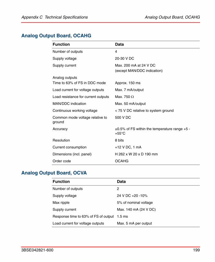
Appendix C Technical Specifications Analog Output Board, OCAHG
3BSE042821-600 199
Analog Output Board, OCAHG
Analog Output Board, OCVA
Function Data
Number of outputs 4
Supply voltage 20-30 V DC
Supply current Max. 200 mA at 24 V DC
(except MAN/DDC indication)
Analog outputs
Time to 63% of FS in DDC mode Approx. 150 ms
Load current for voltage outputs Max. 7 mA/output
Load resistance for current outputs Max. 750
MAN/DDC indication Max. 50 mA/output
Continuous working voltage < 75 V DC relative to system ground
Common mode voltage relative to ground
500 V DC
Accuracy ±0.5% of FS within the temperature range +5 - +55°C
Resolution 8 bits
Current consumption +12 V DC, 1 mA
Dimensions (incl. panel) H 262 x W 20 x D 190 mm
Order code OCAHG
Function Data
Number of outputs 2
Supply voltage 24 V DC +20 -10%
Max ripple 5% of nominal voltage
Supply current Max. 140 mA (24 V DC)
Response time to 63% of FS of output 1.5 ms
Load current for voltage outputs Max. 5 mA per output

Analog Output Board, OCVA Appendix C Technical Specifications
200 3BSE042821-600
Load resistance for current outputs Max. 750
Continuous working voltage < 75 V DC relative to system ground
Common mode voltage relative to ground
500 V DC
Max. recommended cable length 500 m
Accuracy Max. ±0.3%, typ. ±0.15% of FS at 25°C
Temperature stability ±0.002% of FS/°C
Linearity error Max. 0.05%, typ. 0.02% of FS in the temperature range +5 - +55°C
Offset Max. 19.5 mV and 19.5 µA (±4 LSB)
Resolution -10 V - +10 V DC: 12 bits0-10 V DC: 11 bits
4-20 mA: 11 bits
0-20 mA: 11 bits
Current consumption
+12 V DC+ 5 VL
45 mA70 mA
Dimensions (incl. panel) H 262 x W 20 x D 190 mm
Order code OCVA
Function Data

Appendix C Technical Specifications I/O Systems - Series 200 I/O
3BSE042821-600 201
I/O Systems - Series 200 I/ORegarding the technical specifications of the S200 I/O, please refer to any of the manuals:
• S200 I/O Hardware (3BSE021356*)
• S200L and I/O 200C Hardware (3BSE021357*)
• I/O 200C Installation and Maintenance (493104811).

I/O Systems - Series 200 I/O Appendix C Technical Specifications
202 3BSE042821-600

3BSE042821-600 203
Appendix D Troubleshooting
This appendix describes the troubleshooting process for the CI865 on page 203, ControlNet on page 204 and I/O System - Rack I/O on page 207. For more information about troubleshooting Series 200 I/O see I/O System - Series 200 I/O on page 216 for references to relevant manuals.
CI865
Table 21. Satt I/O CI865 – Fault Finding
Designation/Color Function
Neither R(un) nor F(ault) LED’s are ON
The CI865 unit is in the process of being configured. Allow time for this to finalize.
If the condition persists, and no other unit LED on the CEX-Bus is lit:
• Check the CEX-Bus fuse inside the PM8xx processor unit
• Initiate a reset signal (INIT) from the PM8xx processor unit
• Replace the CI865 unit
F(ault) LED is ON The CI865 unit is in the process of being restarted. Allow time for this to finalize.
Replace unit if the condition persists.
COM A LED OFF Power OFF or Reset Mode
COM B LED OFF Normal state (channel B not used)
COM A LED is solid green Channel OK

ControlNet Appendix D Troubleshooting
204 3BSE042821-600
Please refer to the manual AC 800M Controller Hardware, Hardware and Operation (3BSE036351Rxxxx) for more information about troubleshooting of the CI865.
ControlNet
Coax System
Troubleshooting the Repeaters
Follow the troubleshooting step by step. Continue if the error still persist.
COM A LED is solid red Module is broken, has to be replaced
COM A LED is flashing green Temporary error or needs initial setup
COM A LED is flashing red Bad channel cable or node is lonely
COM A LED is flashing red/green
Network has data flow problem
COM A/COM B LED is railroad red
Bad node configuration, for example, duplicate node ID.
COM A/COM B LED is railroad red/green
Self test
Table 22. Troubleshooting the Repeaters
Symptom Measure
Both LEDs are off Unit not powered. 1. Check the power line for correct voltage.2. Check the fuse and replace if blown.
Both LEDs are red Repeater fault. 1. Press the reset switch.2. Replace the repeater or troubleshoot the network.
Table 21. Satt I/O CI865 – Fault Finding (Continued)
Designation/Color Function

Appendix D Troubleshooting Fibre System
3BSE042821-600 205
Fibre System
Troubleshooting the Fiber Repeater Adapter
The repeater adapter has one LED for the coax cable connection and one for the accumulative indication of the fiber channels.
Follow the troubleshooting step by step. Continue if the error still persists.
Either LED flashing green/off
Experiencing temporary network errors. This situation will normally correct itself. If the situation persists, troubleshoot your nodes and cable system. When troubleshooting your cable system, make sure:• all BNC connector pins are properly seated.• all taps are connected properly.• all terminators are 75 and are installed at both ends of
all segments.• the coax cable has not been inadvertently grounded.
Either LED flashing red/off
Experiencing a high level of network errors. This may indicate a broken cable, broken tap or missing segment terminator.
Important! The indicators will flash red/off on a system that has no network activity. This would be normal for a system that has no ControlNet nodes installed or enabled.
Note that any faulty fiber channel normally causes fault indication, but that a faulty channel can be masked by several good fiber channels.
Table 22. Troubleshooting the Repeaters (Continued)
Symptom Measure
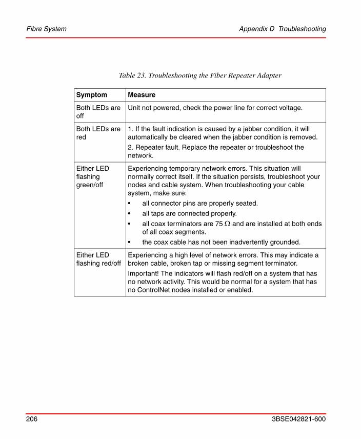
Fibre System Appendix D Troubleshooting
206 3BSE042821-600
Table 23. Troubleshooting the Fiber Repeater Adapter
Symptom Measure
Both LEDs are off
Unit not powered, check the power line for correct voltage.
Both LEDs are red
1. If the fault indication is caused by a jabber condition, it will automatically be cleared when the jabber condition is removed.
2. Repeater fault. Replace the repeater or troubleshoot the network.
Either LED flashing green/off
Experiencing temporary network errors. This situation will normally correct itself. If the situation persists, troubleshoot your nodes and cable system. When troubleshooting your cable system, make sure:
• all connector pins are properly seated.
• all taps are connected properly.
• all coax terminators are 75 and are installed at both ends of all coax segments.
• the coax cable has not been inadvertently grounded.
Either LED flashing red/off
Experiencing a high level of network errors. This may indicate a broken cable, broken tap or missing segment terminator.
Important! The indicators will flash red/off on a system that has no network activity. This would be normal for a system that has no ControlNet nodes installed or enabled.

Appendix D Troubleshooting I/O System - Rack I/O
3BSE042821-600 207
Troubleshooting the Fiber Module
The status indications are individually related to channel 1 or 2:
I/O System - Rack I/O
This section is useful when finding faults that can be detected by the control system or by detection circuits in the rack-based I/O system. Faults which are caused by unintentionally unconnected or faulty inputs/outputs, have to be detected through measures in the application program.
I/O board or I/O rack errors will force the outputs to a safe state. To avoid unpredictable behavior of the process controlled by the system during the troubleshooting, disconnect those parts of the process that are affected by the faulty I/O rack.
The first step, when troubleshooting the rack-based I/O system, is to make sure that the rack(s) are installed properly. Check the cables and the address switches on the PBAD boards. Ensure that the power supplies, PSF, are powered before or simultaneously with the control system. Refer to the LED indicators described in "Power Supply Unit, PSF", on page 125.
Note that there can be additional error information available through the control system software. Refer to the user documentation for the control systems.
Table 24. Troubleshooting the Fiber Module
Symptom Measure
LED is off 1. Unit not powered from the repeater adapter.
2. Faulty module, replace it.
LED is flashing green/off No data activity on associated channel.
Read the section Safety Summary in the beginning of this manual, before performing operations which can be dangerous for personnel or cause damage to equipment.

General Instructions Appendix D Troubleshooting
208 3BSE042821-600
General Instructions
If the I/O communication ceases to function, check the following:
• That connectors are correctly fitted.
• That the indicators on the power supplies in the racks show that the power supply is on.
Rack Adapter Board, 200-RACN
Indications
Symptom Explanation/Measure
OK: Off No power or reset.
1. Check the 24 V DC power (if applicable)2. Check the power supply3. Replace the board
OK: Flashing green
Self-test OK but no connection established with the system.
1. Check the AC 800M system
2. Check the application program
3. Check the network - is there any connection with the AC 800M system?
OK: Solid green On-line, link OK, is connected
OK: Flashing red Recoverable fault, e.g. erroneous board configuration is detected.
1. Check if the expected I/O board configuration, as set up in the program, corresponds to the current configuration in the rack. Make corrections in the program or in the I/O board configuration in the I/O rack.
2. Check the PBAD address.

Appendix D Troubleshooting Rack Adapter Board, 200-RACN
3BSE042821-600 209
OK: Solid red Self-test error, rack error or I/O board error.
Note 1: OK indication will be lit at start up during self-test.
Note 2: If an I/O board- or I/O rack error is detected, the I/O copy will be terminated. Then the STOP indication will also be lit.
Note 3. If one or more external racks are connected, then they must be powered. Otherwise, the OK indication will be solid red.
OK: Solid red
Error indication at start-up
1. Check the node address switches for a valid address. Selected address must be in the interval 02 to 99. After adjusting the switch, the 200-RACN board must be restarted.
2. Check the mode switch. It should be in position 0. After adjusting the switch, the 200-RACN board must be restarted.
3. Check that the power supply units, PSF, in the central rack and external rack(s), are switched on. Switch on the power to all power supplies PSF, and restart the control system.
4. I/O board failure: Check I/O boards by removing the boards and restart the AC 800M system. Replace the faulty board(s).
5. Replace 200-RACN
6. Rack error: Replace the I/O rack.
OK: Solid red
Error indication at run-time
Perform items 3-8 above.
POWER: Off No power
1. Check the 24 V DC power (if applicable)2. Check the power supply 3. Replace 200-RACN
POWER: Solid green
Power applied
STOP: Off I/O copy is running
Symptom Explanation/Measure

Rack Adapter Board, 200-RACN Appendix D Troubleshooting
210 3BSE042821-600
STOP: Solid red No I/O copy is performed, i.e. the I/O-copy has not started yet, or watchdog time-out due to hardware failure.
1. Wait until the PLC program has been downloaded and started.
2. Check the mode switch. It should be in position 0. After adjusting the switch, the 200-RACN board must be restarted.
3. Follow steps 3 to 8 under ”OK: Solid red” indication above.
Com A and B simultaneously:
Off No power or reset
1. Check the 24 V DC power (if applicable)2. Check the power supply3. Replace 200-RACN
Flashing red-green 200-RACN self-test.
Wait until the board self-test is completed.
Flashing red Node configuration error, i.e. duplicated node address.
Check the node address.
Solid red Hardware failure.
Replace 200-RACN
Com A (B disabled)
Off No power or reset
1. Check the 24 V power (if applicable)2. Check the power supply3. Replace 200-RACN
Solid green Channel OK
Symptom Explanation/Measure

Appendix D Troubleshooting Power Supply Unit, PSF
3BSE042821-600 211
Power Supply Unit, PSF
Test Points
Test points for the +5 V DC, +5 VL and +12 V DC outputs are provided on the front panel. The measuring instruments used must have an internal impedance of at least 1 M.
Protection Circuits
The mains supply is protected by a 0.8 AT IEC 5x20 mm fuse. If a 110 V DC supply is used, this fuse should be replaced by a 16 AT IEC fuse. The fuse (F1) is fitted on the front panel for easy access.
The secondary side of the mains transformer is protected by a 5 AT IEC 5x20 mm fuse. This fuse (F2) is fitted on the side of PSF.
Flashing green Temporary network error (communication errors) or network configuration is not downloaded.
1. If constantly flashing, check if the AC 800M system has downloaded the configuration. Check the node addresses on the network. There must be a node No. 1 on the network (the control system).
2. If single flashes (communication error), check the cable system; bad connectors, broken taps, no termination resistor etc.
Flashing red Cable fault or lone node
1. Check if 200-RACN is connected to the network cable.2. Check if there are other active nodes connected to and active on the network.
3. Check the cable system; bad connectors, broken taps, no termination resistor etc.
4. Replace 200-RACN
Solid red Board failure.
Replace 200-RACN
Symptom Explanation/Measure

Digital Input Boards, IDPG24 and IDPG48 Appendix D Troubleshooting
212 3BSE042821-600
A 24 V DC source supply is protected by a 4 AT IEC 5x20 mm fuse. The fuse (F3) is also fitted on the side of PSF.
PSF has semiconductor over-voltage protection for +5 V DC, 5 VL and 12 VDC.
Digital Input Boards, IDPG24 and IDPG48
The system is running:
Digital Input Board, IAPG230
Symptom Measure
The LED status on the input is ON and the control system status is not active
1. Check that the input is not forced to OFF
2. Check that the input voltage is not within the transition region
3. Replace the board
If the LED status on the input is OFF and the control system status is active
1. Check that the input is not forced to ON
2. Replace the board
LED status is OFF and input is active
Replace the board
Symptom Measure
LED status on an input is ON and the control system is not active
1. Check that the input is not forced to OFF
2. Check that the input voltage is not within the transition region
3. Replace the board
If the LED status on an input is OFF and the control system status is active
1. Check that the input is not forced to ON
2. Replace the board
LED status is OFF and input is active
Replace the board

Appendix D Troubleshooting Digital Output Board, ODPG.8
3BSE042821-600 213
Digital Output Board, ODPG.8
The system is running, the supply voltage is on (10-60V) and the output should be activated (by the program):
The system is running and the output should not be activated (by the program).
Symptom Measure
LED status at the output is ON. The output is not active.
1. Check if the output is short circuited to 0 V DC.
* No short circuit - replace the board
* Short circuit - go to step 2
2. Release the cable from the channel and check if the cable is short circuited to 0 V DC
* No short circuit - check the cabling. Correct failures. OK?
LED status at the output is OFF and the output is active
Replace the board
LED status at the output is OFF and the output is not active
Check that the outputs is not forced to OFF
Symptom Measure
LED status at the output is ON and the output is active
Check that the output is not forced to ON
Replace the board
LED status at the output is OFF and the output is active
Loosen the cable attached to the output. Check the voltage level at the output
* +24 V DC - replace the board
* 0 V DC - check the cables

Relay Output Board, ORG24 Appendix D Troubleshooting
214 3BSE042821-600
Relay Output Board, ORG24
Digital Output Board, ODSG
Symptom Measure
LED not lit, no output signal 1. Check that ORG24 is enabled by the switch on the front2. Check that the signal is activated in the control system
3. Replace the board
LED lit, but no output signal 1. Check that 24 V DC is connected at the rear of the rack on the VR screw terminal2. Replace the board
Symptom Measure
PWR LED is not lit Check 24 V DC power supply
Replace the board
Channel LED is not lit, i.e. no output signal
Check that the switch on the front is set to enable position
Check that the signal is activated in the control system
Replace the board
LED lights faintly (if the error flip-flop is active the yellow LED is also lit and F00 for the outputs 00-17 and F20 for 20 - 37 are set high for each group)
Remove overload
Reset the output
Reset the fault bistable circuit if it is used by setting Man/Auto input low for at least 2 ms
Channel LED lit, no output signal
Replace the board

Appendix D Troubleshooting Pulse Counter Board, IPA4
3BSE042821-600 215
Pulse Counter Board, IPA4
Refer to the illustrations "Front panel", on page 141, "Connector X1 with pin numbers for the process signals", on page 149 and "Location of jumpers and DIP switches", on page 150.
The IPA4 board needs no maintenance and a faulty board must be replaced. During normal operation, the change-over switch (10) on the front panel must be in the “I” position. The “0” position resets all the counters and is recommended when the board is removed from the rack.
All inputs have LED indicators on the front panel, which facilitates troubleshooting. The pin numbers for the corresponding cable connections at the rear of the rack are shown on page 148.
The jumpers and DIP switches on a new IPA4 board must be set identically to those of the replaced faulty board. Check the jumpers (1), (2), (3), (4), (6) and the DIP switches (5), (7) carefully according to the illustration on page 150.
Input pulses are compared with a reference voltage 0-10.5 V, which should be adjusted to about half the pulse amplitude by means of the potentiometer (9). The voltage can be measured across the sockets (8). New boards are delivered with the reference adjusted to about +6 V DC.
Analog Input Board, IBA
To be able to trouble-shoot this board, the board should be strapped for 4-20 mA.
Symptom Measure
Erroneous measurement result is registered
Check connections
Check strappings Jxx1, Jxx2, Jxx3, Jxx4, Sxx1, Sxx2 and Sxx3.
Check that units used are properly installed
Replace IBA

Analog Output Board, OCAHG Appendix D Troubleshooting
216 3BSE042821-600
Analog Output Board, OCAHG
To be able to trouble-shoot this board, the board should be strapped for 4-20 mA.
Analog Output Board, OCVA
I/O System - Series 200 I/ORegarding the troubleshooting of the Series 200 I/O, please refer to any of the manuals:
• S200 I/O Hardware- Hardware and Installation (3BSE021356Rxxxx),
• S200L I/O Hardware- Hardware and Installation (3BSE021357Rxxx),
• I/O 200C Installation and Maintenance (493104811).
Symptom Measure
0 mA out constantly Check that OCAHG is enabled by the switch on the front
Check 24 V DC
Check connections
Replace OCAHG
4 mA out constantly Check that 24 V DC is connected to the input ”DDC” on the X1 connector (if run in auto mode and controlled from the system)
Check if the analog signal is activated in the control system.
Replace OCAHG
Erroneous level out (mainly in the lower area)
Check strapping for 4-20 and 0-20 mA
Symptom Measure
Erroneous signal out Check 24 V DC
Check that the straps are properly connected on the ”process connector” for selection of voltage and current
Replace OCVA
3BSE042821-600 217
Appendix E ControlNet Cable Components
This document contains information of ControlNet cable components. Most items contains a brief description and the ABB order code. Component manufacturers are also listed. Since each brand might be represented through different distributors for different countries, no list of distributors is included. In the subsection Tools on page 222 and forward there is a detailed description of how to adjust the cable strip tool.
TapsEach tap kit contains:• 1 m of integral drop cable,• 2 BNC connector kits,• 1 dust cap,• 1 universal mounting bracket,• 2 screws.
Quantity needed: Number of devices + (number of repeaters x 2).

Taps Appendix E ControlNet Cable Components
218 3BSE042821-600
Table 3. Taps
Straight T-tap
Order code TPS
Right angle T-tap
Order code TPR
Straight Y-tap
Order code TPYS
Right angle Y-tap
Order code TPYR

Appendix E ControlNet Cable Components Cables
3BSE042821-600 219
Cables
Table 4. Cables
Trunk cable RG-6: Standard PVC, –40 to +80 °C
ABB
Belden
Comm/Scope
Order code
RG6-PVC
1189A
5740
Trunk cable RG-6: Flooded burial, –55 to +80 °C
Belden
Comm/Scope
Order code
1190A
5740B
Trunk cable RG-6: Plenum-FEP, –70 to +200 °C
ABB
Belden
Comm/Scope
Order code
RG6-FEP
1152A
2227K
Trunk cable RG-6: High-Flex, –40 to +75 °C
ABB
Belden
Comm/Scope
Order code
RG6F
YR28890
5740F
Trunk cable RG-6:Messengered, –40 to +80 °C
Belden
Comm/Scope
Order code
1191A
5740M

Terminators Appendix E ControlNet Cable Components
220 3BSE042821-600
TerminatorsQuantity needed: One for each end of a segment.
Trunk cable RG-6: Armored, –40 to +80 °C
Belden PVC/aluminum
Belden PVC/steel
Comm/Scope
Order code
121189A
131189A
5740A
Trunk cable RG-6: Siamese, –40 to +80 °C
Belden
Comm/Scope
Order code
9072
5740S
Table 5. Terminators
BNC-75 terminator
ABB
Global Comp.
Amphenol
AMP
Order code
BNCT
09C-034
46650-75RFX
221629-5
Table 4. Cables (Continued)
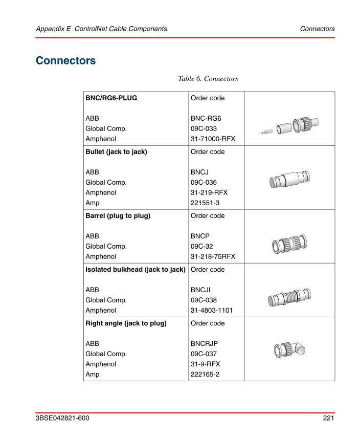
Appendix E ControlNet Cable Components Connectors
3BSE042821-600 221
Connectors
Table 6. Connectors
BNC/RG6-PLUG
ABB
Global Comp.
Amphenol
Order code
BNC-RG6
09C-033
31-71000-RFX
Bullet (jack to jack)
ABB
Global Comp.
Amphenol
Amp
Order code
BNCJ
09C-036
31-219-RFX
221551-3
Barrel (plug to plug)
ABB
Global Comp.
Amphenol
Order code
BNCP
09C-32
31-218-75RFX
Isolated bulkhead (jack to jack)
ABB
Global Comp.
Amphenol
Order code
BNCJI
09C-038
31-4803-1101
Right angle (jack to plug)
ABB
Global Comp.
Amphenol
Amp
Order code
BNCRJP
09C-037
31-9-RFX
222165-2

Tools Appendix E ControlNet Cable Components
222 3BSE042821-600
Tools
Table 7. Tools
ControlNet Tool Kit Complete: Tools for installation of cable connectors, including extra connectors
Order code: CTK
Crimp tool
ABB
Weidmüller-Paladin Tools
Order code
CTOOL
1349AB
Crimp die
ABB
Weidmüller-Paladin Tools
Order code
CDIE
2082
Strip tool with blade cassette and PVC memory blade holder
ABB
Weidmüller-Paladin Tools
Order code
STOOL
1247AB
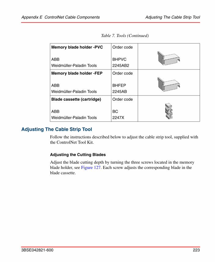
Appendix E ControlNet Cable Components Adjusting The Cable Strip Tool
3BSE042821-600 223
Adjusting The Cable Strip Tool
Follow the instructions described below to adjust the cable strip tool, supplied with the ControlNet Tool Kit.
Adjusting the Cutting Blades
Adjust the blade cutting depth by turning the three screws located in the memory blade holder, see Figure 127. Each screw adjusts the corresponding blade in the blade cassette.
Memory blade holder -PVC
ABB
Weidmüller-Paladin Tools
Order code
BHPVC
2245AB2
Memory blade holder -FEP
ABB
Weidmüller-Paladin Tools
Order code
BHFEP
2245AB
Blade cassette (cartridge)
ABB
Weidmüller-Paladin Tools
Order code
BC
2247X
Table 7. Tools (Continued)

Adjusting The Cable Strip Tool Appendix E ControlNet Cable Components
224 3BSE042821-600
Adjust the three screws until the strip tool makes these cuts in the cable:
Figure 127. Cable strip tool, adjusting the cutting blades.
Figure 128. Stripped cable; layers and dimensions.
2
3
1
Adjusting screws for cutting outer sheath (1), the wire braid and the other layers down to the white insulation (2), the white insulation down to the center conductor (3).
To increase the cut depth –turn the screw clockwise.
To decrease the cut depth – turn the screw counterclockwise.
Sheath

Appendix E ControlNet Cable Components Adjusting The Cable Strip Tool
3BSE042821-600 225
1. Braid/Tape/Braid/Tape The first cut should cut the outer sheath without cutting the outer wire braid.
2. White insulation or 1st tape. The second blade should cut the sheath, the three outer shields and possibly the inner tape shield. The insulation can be scored slightly, but should not have a deep cut.
3. Center conductor. The third blade should cut all layers of the cable down to the center conductor. This cut should not score the center conductor.
Reversing/Replacing the Cutting Blades
To reverse or change the cutting blades:
1. Use a screwdriver to lift the memory blade holder and swing it back.
Important: The first and second blade adjustments need to be very precise. Adjustments as small as 2 to 3 mm can make the difference between a perfect and an imperfect cut.
Figure 129. Lifting the memory blade holder.

Adjusting The Cable Strip Tool Appendix E ControlNet Cable Components
226 3BSE042821-600
2. Slide the memory blade cartridge out of the strip tool.
Figure 130. Taking out the memory blade cartridge.
If you are reversing the memory blade cartridge to use the second set of blades – go to step 3.
If you are replacing the memory blade cartridge – go to step 4.

Appendix E ControlNet Cable Components Adjusting The Cable Strip Tool
3BSE042821-600 227
3. Flip the memory blade cartridge and slide it back into the strip tool.
If you are replacing the memory blade cartridge – go to step 4, otherwise go direct to step 5.
Figure 131. Reversing the memory blade cartridge.

Adjusting The Cable Strip Tool Appendix E ControlNet Cable Components
228 3BSE042821-600
4. Align the memory blade cartridge (the side with the raised notches) to the raised area on the inside of the strip tool and slide the new memory blade cartridge in.
5. Swing the memory blade holder closed.
The blades should be on top as you slide the cartridge.
Figure 132. Replacing the memory blade cartridge.
Figure 133. Closing the memory blade holder.

Appendix E ControlNet Cable Components Adjusting The Cable Strip Tool
3BSE042821-600 229
Changing the Memory Blade Holder
You received two memory blade holders with your cable strip tool; one is for PVC-CL2 cable, and the other is for plenum FEP-CL2P cable. You need to install the appropriate memory blade holder for the type of cable you are stripping (PVC or FEP).
1. Lift the latches on the memory blade holder and swing it back.
2. Snap the memory blade holder off the rod and remove it from the strip tool.
Figure 134. Lifting the memory blade holder.
Figure 135. Removing the memory blade holder.

Adjusting The Cable Strip Tool Appendix E ControlNet Cable Components
230 3BSE042821-600
3. Position the appropriate memory blade holder on the rod and snap the holder into place.
4. Swing the memory blade holder closed.
Figure 136. Closing the memory blade holder.

Appendix E ControlNet Cable Components Coax Repeaters
3BSE042821-600 231
Coax Repeaters
Fiber Repeaters
Figure 137. Coax Repeaters
Figure 138. Fiber Repeaters
Coax repeater RPTfor input voltage 85–250 V AC
Coax repeater RPTDfor input voltage 20–72 V DC
Fiber repeater adapter RPA Fiber repeater module RPFM and RPFS

Fiber Repeaters Appendix E ControlNet Cable Components
232 3BSE042821-600

3BSE042821-600 233
Appendix F Rack I/O Parts List
Order code Product description
200-RACN Rack adapter board for remote rack-based I/O system connected to the AC 800M system
200-RACN/A Rack adapter board, 200-RACN, with analog-to-digital converter ADSF mounted
PSF Power supply unit
IDPG24 Digital input board with 32 inputs, 24 V DC
IDPG48 Digital input board with 32 inputs, 48 V DC
IAPG230 Digital input board with 16 inputs, 230 V AC
IPA4 Pulse counter board with 4 inputs, 8-bit counters
IBA Analog input board with 8 inputs
MCV200 Analog module for IBA, which permits up to 200 V DC common-mode voltage for each channel, individually
MCVG Analog module for IBA, which provides individual galvanic separation of up to 750 V DC per channel
MP100, MP200MP400, MP600MP130, MP160
Temperature modules for IBA, to be used when measuring the temperature with Pt100 sensor. MP is linearized
MN80 Temperature module for IBA, to be used when measuring the temperature with Ni1000 sensor. MN is not linearized
MR100MR140MR1000
Resistance modules for IBA, to be used when measuring resistance (position sensing, pressure measurement etc.)
ODPG.8 Digital output board with 32 outputs

Appendix F Rack I/O Parts List
234 3BSE042821-600
ORG24 Relay output board with 16 outputs
ODSG Digital output board with 32 optocoupled outputs, short-circuit-proof
OCAHG Analog output board with 4 outputs
OCVA Analog output board with 2 outputs
PIOS/RC Basic rack PIOS35 with address panel, power supply, PSF, and 200-RACN
PIOS/RCA Basic rack PIOS35 with address panel, power supply, PSF, and 200-RACN/A
PIOS/P Basic rack PIOS35 with address panel, power supply, PSF, bus interconnection socket XPIOS and bus decoder board, PBAD (also includes screws and mounting devices)
PIOS35 Empty basic rack (to be used as external or central rack)
ADSF Central A/D converter. To be mounted on rack adapter board 200-RACN
PTU2 Two ready-wired I/O connectors with cables and screw terminal blocks mounted on an aluminium profile
CRT01 Crimp tool for 0.14-0.5 mm2 cables
CRT02 Crimp tool for 0.75-1.5 mm2 cables
CRIMP1 Crimp sleeve for 0.14-0.5 mm2 cables
CRIMP2 Crimp sleeve for 0.75-1.5 mm2 cables
CRRE Crimped connection removal tool
AP1740 Address panel 1000-1740
AP2740 Address panel 2000-2740
I/OPAN6HE4TE Blanking panel, PANEL1. Covers one slot, 6U
I/OPAN6HE8TE Blanking panel, PANEL2. Covers two slots, 6U
FPA1S to FPA9S Blanking panel between racks. Covers 19”, 1 U to 9 U
Order code Product description

Appendix F Rack I/O Parts List Recommended Components
3BSE042821-600 235
Recommended Components
PTC Digital simulation board with a panel which has 32 switches for simulation of digital inputs
IVAPOT Analog simulation board with 8 potentiometers for simulation of analog inputs
Components to the ControlNet network is listed in Appendix E, ControlNet Cable Components.
Order code Name/Function
– Ground clamps (spring clamps) for shielded cables- Weidmüller KLB 1-8 (for cables 1 - 8 mm)
- Weidmüller KLB 4-13.5 (for cables 4 - 13.5 mm)
_ Capacitor for earth reference.- Phoenix TT SLKK 5-C12n230VAC
Order code Product description

Recommended Components Appendix F Rack I/O Parts List
236 3BSE042821-600

3BSE042821-600 237
Appendix G Standards
CSA Hazardous Location ApprovalCSA certifies products for general use as well as for the use in hazardous locations. Actual CSA certification is indicated by the product label as shown below, and not by statements in any user documentation.
Example of the CSA1 certification product label:
To comply with CSA certification for use in hazardous locations, the following information becomes a part of the product literature for this CSA-certified industrial control product.
• This equipment is suitable for use in Class 1, Division 2, Groups A, B, C, D, or non-hazardous locations only.
• The products having the appropriate CSA markings (that is, Class 1, Division 2, Groups A, B, C, D) are certified for use in other equipment where the suitability of combination (that is, application or use) is determined by the CSA or the local inspection office having jurisdiction.
Important: Due to the modular nature of a programmable control system, the product with the highest temperature rating determines the overall temperature code rating of a programmable control system in a Class 1, Division 2 location. The temperature code rating is marked on the product label as shown.
1. CSA logo is a registered trademark of the Canadian Standards Association.
CL 1 DIV 2GP A,B,C,D
TEMP
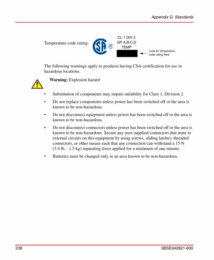
Appendix G Standards
238 3BSE042821-600
Temperature code rating:
The following warnings apply to products having CSA certification for use in hazardous locations.
• Substitution of components may impair suitability for Class 1, Division 2.
• Do not replace components unless power has been switched off or the area is known to be non-hazardous.
• Do not disconnect equipment unless power has been switched off or the area is known to be non-hazardous.
• Do not disconnect connectors unless power has been switched off or the area is known to be non-hazardous. Secure any user-supplied connectors that mate to external circuits on this equipment by using screws, sliding latches, threaded connectors, or other means such that any connection can withstand a 15 N (3.4 lb. - 1.5 kg) separating force applied for a minimum of one minute.
• Batteries must be changed only in an area known to be non-hazardous.
Warning: Explosion hazard
CL 1 DIV 2GP A,B,C,D
TEMPLook for temperature code rating here

Appendix G Standards
3BSE042821-600 239
Approbation d‘utilisation dans des emplacements dangereux par la CSA
La CSA certifie les produits d’utilisations générale aussi bien que ceaux qui s’utilisent dans des emplacements dangereux. La certification CSA en vigueur est indiquée par l’étiquette du produit et non par des affirmations dans la documentation à l’usage des utilisateurs.
Example d’étiquette de certification d’un produit par la CSA1:
Pour satisfaire à la certification de la CSA dans des endroits dangereux, les informations suivantes font partie intégrante de la documentation des produits industriels de contrôle certifiés par la CSA.
• Cet équipement convient á l’utilisation dans des emplacements de Classe 1, Division 2, Groupes A, B, C, D, ou ne convient qu’á l’utilisation dans des endroits non dangereux.
• Les produits portant le marquage approprié de la CSA (c’est à dire, Classe 1, Division 2, Groupes A, B, C, D) sont certifiés à l’utilisation pour d’autres équipements où la convenance de combinaison (application ou utilisation) est déterminée par la CSA ou le bureau local d’inspection qualifié.
Important: Par suite de la nature modulaire du système de contrôle programmable, le produit ayant le taux le plus élevé de température détermine le taux d’ensemble du code de température du système de contrôle programmable dans un emplacement de Classe 1, Division 2. Le taux du code de température est indiqué sur l’étiquette du produit.
Taux du code detémperature:
1. Le sigle CSA est la marque déposée de l’Association des Standards pour le Canada.
CL 1 DIV 2GP A,B,C,D
TEMP
CL 1 DIV 2GP A,B,C,D
TEMPLe taux de code de température est indiqué ici

Appendix G Standards
240 3BSE042821-600
Les avertissements suivants s’appliquent aux produits ayant la certification CSA pour leur utilisation dans des emplacements dangereux.
• La substitution de composants peut rendre ce matériel inacceptable pour les emplacements de Classe 1, Division 2.
• Couper le courant ou s’assurer que l’emplacement est désigné non dangereux avant de remplacer les composants.
• Avant de débrancher l’équipment, couper le courant ou s’assurer que l’emplacement est désigné non dangeruex.
• Avant de débrancher les connecteurs, couper le courant ou s’assurer que l’emplacement est reconnu non dangereux. Attacher tous connecteurs fournis par l’utilisateur et reliés aux circuits externes de l’appareil à l’aide de vis, loquets coulissants, connecteurs filetés ou autres moyens permettant aux connexions de résister à une force de séparation de 15 N (3,4 lb. - 1,5 kg) appliquée pendant au moins une minute.
• Afin d’éviter tout risque d’éxplosion, s’assurer que l’emplacement est designé non dangereux avant de changer la batterie.
Avertissement: Risque d éxplosion:

3BSE042821-600 241
Appendix H Directive Considerations
Electromagnetic Compatibility (EMC)Units mentioned in this document for which the product is marked with the logo are tested to meet Council Directive 89/336, Electromagnetic Compatibility (EMC) using a technical construction file, and meet the following EMC standards, applicable in whole or in part:
• EN 61131-2 Product Standard, Programmable Controller – Industrial Environment
• EN 61000-6-2 EMC – Generic Immunity Standard, Part 2 – Industrial Environment
• EN 61000-6-4 EMC – Generic Emission Standard, Part 2 – Industrial Environment
Low-Voltage Directive (LVD)Units mentioned in this document for which the product is marked with the logo comply with the LVD where applicable, i.e. if they are connected to 50 - 1000 V AC and/or 75 - 1500 V DC.
Note that the units are “Open type equipment” and must be mounted in suitable cabinets.
Note also that external power supplies used to provide 24 V DC must be CE-marked. The CE low-voltage directive prescribes that a safety extra low voltage (SELV) or a protected extra low voltage (PELV) power supply be used.

Appendix H Directive Considerations
242 3BSE042821-600

3BSE042821-600 243
Numerics200-ACN 20, 28, 39200-AENTR 23, 39200-RACN 20, 38, 46, 121, 186, 234200-RACN/A 46, 121
AAC 800M Controller 23Address panel 234Address panel AP1740 234Addressing methods 49Addressing restrictions 49ADSF 46
mounting 124Analog input board
IBA 153, 160, 194, 215Analog output board
OCAHG 165, 199, 216OCVA 170, 199, 216
Analog simulation board IVAPOT 174Analog simulation board, IVAPOT 235
BBlanking panel 234BNC-connector 116Board layout 150Bracket assembly 83Bus system 39
CCable connection
IPA4 147Cable strip tool
Adjusting the cable strip tool 223Cutting blades 223, 225
Memory blade 229Cables
Attaching connectors 92Layers 88Length limitations 70, 74Routing 67Stripping 85Stripping dimensions 88Types 59, 72, 219
Chamber gauge ring 86Change-over switch 138, 141Changing the memory blade holder 229Clear signals
IPA4 146Color coding 49Conductors
Categories 66Connecting 106
Fiber repeater adapter 112Fiber repeater unit 113RACN 123
Connector body 96Connectors 64, 221
Barrel 64Bullet 64Cable 64Jack-to-jack 65Jack-to-plug 65X1 38X2 38, 51
ControlNet 20Cable System 27
ControlNet cable systemCable components 217Surge suppression 69
INDEX

Index
244 3BSE042821-600
Index
244 3BSE042821-600
Counter channels 141Crimp ferrule 94Crimp removal tool 53Crimp sleeve 52, 234
CRIMP1 53, 234CRIMP2 53, 234
Crimp tool CRT01 53, 234Crimp tool CRT02 53, 234CSA certification 237Cutting chamber 86
DDDC 20Description
200-RACN 46, 233200-RACN/A 46, 233ADSF 46, 234IAPG230 233IBA 233IDPG24 233IDPG48 233IPA4 233MCV200 233MCVG 233MN80 233Modules to IBA 46MP 233MR 233OCAHG 234OCVA 234ODPG8 233ODSG 234ORG 234PIOS/DR 47PIOS/DRA 47PIOS/P 234PIOS/R 234PIOS/RA 234PIOS35 46, 234PSF 46, 233
PTU2 46Digital input board
IAPG230 129, 189, 212IDPG 188IDPG24 127, 188, 212IDPG48 127, 188, 212IPA4 140, 193, 215
Digital output boardODPG.8 131, 190, 213ODSG 137, 192, 214ORG24 134, 191, 214
Digital simulation boardPTC 174, 235
DIN-rail 116DIP switches
IAP4 144IPA4 152
EEdge connector for I/O cards, ready wired 54Electrostatic or magnetic fields 44EMC directive 241EMC directive 89/336/EEC 38, 185Environments 44EtherNet/IP 23Evaluation logic
IPA4 144
FFiber
Chain of repeaters 72Connector panel 72Network configuration 37Optic cable 36, 107Optic link 20Power loss measurement 74, 107Repeater adapter 20, 35, 70, 112, 179, 184,
231Repeater configuration 114Repeater module 20, 36, 71, 179, 184, 231

Index
3BSE042821-600 245
Repeater unit 113Troubleshooting the fiber module 207Troubleshooting the fiber repeater adapter 205
Filters 38
GGeneral planning 69Ground reference
ODPG.8 131ODSG 139
Grounding precautions 58, 65
II/O Addressing 49, 120I/O board
Installation and function 121IBA 153, 215
Connections 157jumpers 153
Input circuitsIPA4 142
Installing200-RACN 121Cable Connectors 84Coax Cable System 80Fiber Optic System 107ORG24 134Power source to 200-ACN 55PSF 125Satt I/O Units and CI865 116
Integral drop cable 29IPA4 140, 215IVAPOT 174, 235
JJumpers
IBA 153IPA4 150 to 151
LLightning 70Limitations
200-RACN 119Node address 119Repeaters 119
List of ControlNet cable components 217
MMains supply
Voltage, power supply unit 126Maximum cable length 119Modules for IBA
MCV200 160, 195MCVG 160, 195MN 160MP 160, 196MP, MN and MR 196MR 160
MountingBracket 83Coax repeaters 183Dimensions 181Fiber module 184Fiber repeater 184Fiber units 109Taps 81Universal mounting bracket 82
NNetwork 21, 31
Address range 32Configuration with fibre modules 37Planning 70
Network parameters 75Network Update Time (NUT) 79Node 21
Maximum number 58Node address
200-ACN 117

Index
246 3BSE042821-600
Index
246 3BSE042821-600
200-RACN 117CI865 117
OOCAHG 216OCVA 216
Installation instructions 173OTDR 108Output circuits
IPA4 147Output relay board ORG24 190
PPin assignment
ODPG.8 132ORG24 134
PIOS35 21, 38, 46, 125Mains Supply 51
PlanningCoax Cable System 58Fiber Optic Links 70Repeaters and the Network Size 75
Positioning 140Power supply unit, PSF 38, 187Propagation delay 79Protection circuits
PSF 126, 211PSF 21, 38, 46, 51, 125, 187PTC 174, 235PTU2 21, 46, 54Pulse counter board
IPA4 140Pulse counter board IPA4 193Pulse counter signals 52Pulse detection 140
QQuantity counting 140
RRack adapter board
200-RACN 185Rack-based I/O 38, 41, 46Remote rack-based I/O system 46Repeaters 33, 63, 231
Explanation 20In parallel 105In series 104Network configuration 64Number of 75Troubleshooting 204
RPA 20, 35, 70, 112, 179, 184, 205, 231RPFM 20, 36, 71, 113, 180, 184, 207RPFM and RPFS 113, 231RPT 177, 183, 231RPTD 178, 183, 231
SSatt ControlNet 25, 41, 46, 55, 58, 120Satt I/O 17, 23, 116Sections
Length 60Segments 31
Calculation 61Explanation 21Planning 69
Series 200 I/O 17, 23, 39, 41, 43, 55, 116 to 117, 201
Speed calculation 140Spring clamps 53Stripping dimensions 88Surge suppression 69
TTaps 21, 29, 58, 81, 116, 181, 217TDR 96Terminators 21, 31, 62, 220Test and simulation equipment 174Testing for electrical shorts 91, 95

Index
3BSE042821-600 247
Tool box 84, 222Troubleshooting
200-RACN 208Analog input board 215Analog output board 216CI865 203Digital input board 215Digital input boards 212Digital output boards 213 to 214PSF 211Series 200 I/O 216The coax repeater 204The fiber module 207The fiber repeater adapter 205
Trunk cable 116Trunk line
Cable 30Trunkline
Definition 21Section 21
UUL Listing 18Universal mounting bracket 182
WWiring
External to enclosures 67, 81General guidelines 67Inside enclosures 68, 81
Wiring guidelines 67
XX1 Connector 38, 50
IBA 153IDPG24 127, 129IPA4 147ODSG 139ORG24 134
X2 Connector 38, 51, 124, 147

Index
248 3BSE042821-600
Index
248 3BSE042821-600


Power and productivityfor a better worldTM
Contact us
Copyright© 2003-2014 ABB.All rights reserved.
3BS
E04
2821
-600www.abb.com/800xA
www.abb.com/controlsystems