abstract of phd. thesis - aparate.elth.ucv.roaparate.elth.ucv.ro/doctorat/abstract of phd. thesis -...
TRANSCRIPT
UNIVERSITY OF CRAIOVAELECTRICAL ENGINEERING FACULTY
M.Sc. Alin-Iulian DOLAN
ABSTRACT OF PHD. THESISContributions to modeling of the fields and ofthe transient regimes in electrical equipments
Scientific coordinator:Prof. Grigore A. CIVIDJIAN
CRAIOVA, 2009
Alin-Iulian DOLAN – Contributions to modeling of the fields and of the transient regimes in electrical equipments
Abstract of PhD. Thesis 2
ACKNOWLEDGEMENTS
I owe my deepest gratitude to scientific coordinator, Prof. Grigore A. Cividjian, forvery meticulous guidance, scientific advices and critical comments, extremely valuable inaccomplishing this work.
m honored by and I thank to Prof. Andrei ugulea, member of Romanian Academy,to Prof. Mihai Iordache, Prof. Dumitru Topan and Prof. Ioan Popa, for accepting to makethe peer review of the thesis.
Thank once again to Prof. Dumitru Topan and to Prof. Ioan Popa, for theencouragements given at the appropriate time for undertaking steps in obtaining abroadinternships, which have enriched my scientific and linguistic horizon.
Also thank to the University Agency for Francophonie, for the financial support toachieve the inter-university mobility and to Prof. Serge Monchaud from the National Instituteof Applied Sciences in Rennes, for the careful coordination of its beginning in the TechnicalUniversity of Sofia.
Thank to the French Institute in Sofia, for its hospitality and special support in rapidassimilation of the French language.
I want to thank Prof. Ivan Yatchev from Technical University of Sofia, for his greathospitality and assistance in using the ANSYS program, along the research internshipsundertaken at the Doctoral School from this university, making possible the extension of thenumerical simulations related to Chapters III and IV.
Thank, by this way, to Prof. Leonardo-Geo M nescu, for kindly helped to me incontacting the professors and specialists from Grenoble Electrical Engineering Laboratory,referring Prof. Gérard Meunier, Prof. Albert Foggia and Prof. Thierry Chevalier, whom Ithank for their hospitality and support in using the FLUX program, along the researchinternship undertaken at this laboratory.
In the same time I thank to CEDRAT Company in Grenoble for the rights of personaluse of the FLUX program, which had allowed the numerical simulation related to thechapters V and VI.
I want to thank all colleagues in the Department of Electrical apparatus andtechnologies, for many encouragements and very useful advices along this work.
I thank and am deeply grateful to my family for the moral support, the understandingand patience, constantly exhibited, helping me to finalize this thesis.
Alin-Iulian DOLAN – Contributions to modeling of the fields and of the transient regimes in electrical equipments
Abstract of PhD. Thesis3
SUMMARYAbbreviations list . . . . . . . . . . . . . . . . . . . . . . . . . . . . . . . . . . . . . . . . . . . . . . . . . . . . . . . . . . . . . . . . . . . . . . . . . . . . . . . . . . 9 (5)
INTRODUCTION . . . . . . . . . . . . . . . . . . . . . . . . . . . . . . . . . . . . . . . . . . . . . . . . . . . . . . . . . . . . . . . . . . . . . . . . . . . . . . . . . . 11 (6)
1 FINITE ELEMENT METHOD FORMULATIONS . . . . . . . . . . . . . . . . . . . . . . . . . . . . . . . . . . . . . . . . . . . . . . . . . . 13 (7)
1.1 Introduction . . . . . . . . . . . . . . . . . . . . . . . . . . . . . . . . . . . . . . . . . . . . . . . . . . . . . . . . . . . . . . . . . . . . . . . . . . . . . . . 131.2 Projective formulation . . . . . . . . . . . . . . . . . . . . . . . . . . . . . . . . . . . . . . . . . . . . . . . . . . . . . . . . . . . . . . . . . . . . . . . . 15 (7)
1.2.1 Weighted residues method . . . . . . . . . . . . . . . . . . . . . . . . . . . . . . . . . . . . . . . . . . . . . . . . . . . . . . . . . . . . . . 171.3 Variational formulation . . . . . . . . . . . . . . . . . . . . . . . . . . . . . . . . . . . . . . . . . . . . . . . . . . . . . . . . . . . . . . . . . . . . . . 18 (7)1.4 Unknown functions approximation . . . . . . . . . . . . . . . . . . . . . . . . . . . . . . . . . . . . . . . . . . . . . . . . . . . . . . . . . . . . . 19 (7)1.5 Finite element method formulations in Magneto statics . . . . . . . . . . . . . . . . . . . . . . . . . . . . . . . . . . . . . . . . . . . . . . 22 (7)
1.5.1 FEM in magnetic scalar potential formulation (MSP) . . . . . . . . . . . . . . . . . . . . . . . . . . . . . . . . . . . . . . . . . 23 (7)1.5.1.1 Reduced MSP formulation (MSPr) . . . . . . . . . . . . . . . . . . . . . . . . . . . . . . . . . . . . . . . . . . . . . . . . 231.5.1.2 Total MSP formulation (MSPt). . . . . . . . . . . . . . . . . . . . . . . . . . . . . . . . . . . . . . . . . . . . . . . . . . . 241.5.1.3 Difference MSP formulation (MSPd) . . . . . . . . . . . . . . . . . . . . . . . . . . . . . . . . . . . . . . . . . . . . . . 241.5.1.4 Generalized MSP formulation (MSPg) . . . . . . . . . . . . . . . . . . . . . . . . . . . . . . . . . . . . . . . . . . . . . 251.5.1.5 Edge MSP formulation (MSPe) . . . . . . . . . . . . . . . . . . . . . . . . . . . . . . . . . . . . . . . . . . . . . . . . . . 26
1.5.2 FEM in magnetic vector potential formulation (MVP) . . . . . . . . . . . . . . . . . . . . . . . . . . . . . . . . . . . . . . . . 27 (7)1.5.3 FEM in edge element formulation (EE) . . . . . . . . . . . . . . . . . . . . . . . . . . . . . . . . . . . . . . . . . . . . . . . . . . . . 29 (8)
1.6 Conclusions . . . . . . . . . . . . . . . . . . . . . . . . . . . . . . . . . . . . . . . . . . . . . . . . . . . . . . . . . . . . . . . . . . . . . . . . . . . . . . . . 31
2 INDUCTANCE OF PLUNGER-TYPE ELECTROMAGNET . . . . . . . . . . . . . . . . . . . . . . . . . . . . . . . . . . . . . . . . . . 33 (8)
2.1 Introduction . . . . . . . . . . . . . . . . . . . . . . . . . . . . . . . . . . . . . . . . . . . . . . . . . . . . . . . . . . . . . . . . . . . . . . . . . . . . . . . . 33 (8)2.2 Power approximation of boundary conditions method (PABCM) . . . . . . . . . . . . . . . . . . . . . . . . . . . . . . . . . . . . . . 33 (8)2.3 Utilization of PABCM to the inductance of plunger-type electromagnet computation . . . . . . . . . . . . . . . . . . . . . . 36 (9)
2.3.1 Computation of F(α, z) function . . . . . . . . . . . . . . . . . . . . . . . . . . . . . . . . . . . . . . . . . . . . . . . . . . . . . . . . . 362.3.2 Computation of intern inductance of plunger-type electromagnet 1 . . . . . . . . . . . . . . . . . . . . . . . . . . . . . . 40 (9)2.3.3 Numerical solution and experimental verification . . . . . . . . . . . . . . . . . . . . . . . . . . . . . . . . . . . . . . . . . . . . 43 (10)2.3.4 IPTM application. . . . . . . . . . . . . . . . . . . . . . . . . . . . . . . . . . . . . . . . . . . . . . . . . . . . . . . . . . . . . . . . . . . . . . 47
2.4 Conclusions . . . . . . . . . . . . . . . . . . . . . . . . . . . . . . . . . . . . . . . . . . . . . . . . . . . . . . . . . . . . . . . . . . . . . . . . . . . . . . . . 48
3 STATIC CHARACTERISTIC OF A PLUNGER-TYPE ELECTROMAGNET . . . . . . . . . . . . . . . . . . . . . . . . . . . 49 (11)
3.1 Introduction . . . . . . . . . . . . . . . . . . . . . . . . . . . . . . . . . . . . . . . . . . . . . . . . . . . . . . . . . . . . . . . . . . . . . . . . . . . . . . . . 493.2 Numerical computation of electromagnetic forces . . . . . . . . . . . . . . . . . . . . . . . . . . . . . . . . . . . . . . . . . . . . . . . . . . 50 (11)
3.2.1 Maxwell stress tensor method (MTM) . . . . . . . . . . . . . . . . . . . . . . . . . . . . . . . . . . . . . . . . . . . . . . . . . . . . . 50 (11)3.2.2 Virtual work method (VWM) . . . . . . . . . . . . . . . . . . . . . . . . . . . . . . . . . . . . . . . . . . . . . . . . . . . . . . . . . . . 54 (11)3.2.3 Equivalent sources method (ESM) . . . . . . . . . . . . . . . . . . . . . . . . . . . . . . . . . . . . . . . . . . . . . . . . . . . . . . . 58
3.3 Numerical determination of static characteristic of plunger-type electromagnet 2 and experimental verification. . 60 (12)3.4 Theoretical determination of static characteristic of plunger-type electromagnet 2 . . . . . . . . . . . . . . . . . . . . . . . . . 68 (13)3.5 Conclusions . . . . . . . . . . . . . . . . . . . . . . . . . . . . . . . . . . . . . . . . . . . . . . . . . . . . . . . . . . . . . . . . . . . . . . . . . . . . . . . . 70
4 LEAKAGE MAGNETIC FIELD AND MODELING LIGHTNING SURGES IN POWER MULTI-WINDINGAUTOTRANSFORMER . . . . . . . . . . . . . . . . . . . . . . . . . . . . . . . . . . . . . . . . . . . . . . . . . . . . . . . . . . . . . . . . . . . . . . . . . 71 (15)
4.1 Introduction . . . . . . . . . . . . . . . . . . . . . . . . . . . . . . . . . . . . . . . . . . . . . . . . . . . . . . . . . . . . . . . . . . . . . . . . . . . . . . . 714.2 Leakage reactance. Impedance voltage . . . . . . . . . . . . . . . . . . . . . . . . . . . . . . . . . . . . . . . . . . . . . . . . . . . . . . . . . . 74
4.2.2 No load test at rated voltage . . . . . . . . . . . . . . . . . . . . . . . . . . . . . . . . . . . . . . . . . . . . . . . . . . . . . . . . . . . . . 764.2.3 Short-circuit test at reduced voltage and rated current . . . . . . . . . . . . . . . . . . . . . . . . . . . . . . . . . . . . . . . . . 77
4.3 Impedance voltage of the power multi-winding autotransformer . . . . . . . . . . . . . . . . . . . . . . . . . . . . . . . . . . . . . . 79 (15)4.3.1 Primary-secondary windings pair . . . . . . . . . . . . . . . . . . . . . . . . . . . . . . . . . . . . . . . . . . . . . . . . . . . . . . . . . 80 (15)4.3.2 Tertiary-primary winding pair . . . . . . . . . . . . . . . . . . . . . . . . . . . . . . . . . . . . . . . . . . . . . . . . . . . . . . . . . . . 814.3.3 Tertiary-secondary winding pair . . . . . . . . . . . . . . . . . . . . . . . . . . . . . . . . . . . . . . . . . . . . . . . . . . . . . . . . . 81
4.4 Numerical evaluation of the magnetic field energy and of the short-circuit reactance with FEMM program . . . . 82 (16)4.4.1 2-D model and the boundary conditions . . . . . . . . . . . . . . . . . . . . . . . . . . . . . . . . . . . . . . . . . . . . . . . . . . . . 82 (16)4.4.2 2-D numerical results of short-circuit tests . . . . . . . . . . . . . . . . . . . . . . . . . . . . . . . . . . . . . . . . . . . . . . . . . 85 (17)
4.5 Numerical evaluation of the magnetic field energy and of the short-circuit reactance with ANSYS program . . . 88 (17)4.5.1 3-D model and the boundary conditions . . . . . . . . . . . . . . . . . . . . . . . . . . . . . . . . . . . . . . . . . . . . . . . . . . . . 884.5.2 3-D numerical results of short-circuit tests . . . . . . . . . . . . . . . . . . . . . . . . . . . . . . . . . . . . . . . . . . . . . . . . . 894.5.3 Optimization of 3-D simulations by memory management . . . . . . . . . . . . . . . . . . . . . . . . . . . . . . . . . . . . . 92 (18)
4.6 Modeling lightning surges in the power multi-winding autotransformer . . . . . . . . . . . . . . . . . . . . . . . . . . . . . . . . . 94 (18)4.6.1 Short-circuited tertiary winding influence . . . . . . . . . . . . . . . . . . . . . . . . . . . . . . . . . . . . . . . . . . . . . . . . . . 944.6.2 Self and mutual inductances for short-circuited tertiary winding . . . . . . . . . . . . . . . . . . . . . . . . . . . . . . . . 96 (18)4.6.3 Capacitance of a pair of interlinked winding disks . . . . . . . . . . . . . . . . . . . . . . . . . . . . . . . . . . . . . . . . . . . 984.6.4 Simple model for lightning surges on free end of regulating winding . . . . . . . . . . . . . . . . . . . . . . . . . . . . 99
4.7 Conclusions . . . . . . . . . . . . . . . . . . . . . . . . . . . . . . . . . . . . . . . . . . . . . . . . . . . . . . . . . . . . . . . . . . . . . . . . . . . . . . . 101
Alin-Iulian DOLAN – Contributions to modeling of the fields and of the transient regimes in electrical equipments
Abstract of PhD. Thesis 4
5 NUMERICAL SIMULATION OF TRANSIENT ELECTRIC AND MAGNETIC FIELDS INRECTANGULAR SOLID BUS BARS . . . . . . . . . . . . . . . . . . . . . . . . . . . . . . . . . . . . . . . . . . . . . . . . . . . . . . . . . . . . 103 (20)
5.1 Introduction . . . . . . . . . . . . . . . . . . . . . . . . . . . . . . . . . . . . . . . . . . . . . . . . . . . . . . . . . . . . . . . . . . . . . . . . . . . . . . 1035.2 Analytical evaluation of magnetic field distribution . . . . . . . . . . . . . . . . . . . . . . . . . . . . . . . . . . . . . . . . . . . . . . . 104 (20)
5.2.1 Exterior magnetic field distribution . . . . . . . . . . . . . . . . . . . . . . . . . . . . . . . . . . . . . . . . . . . . . . . . . . . . . 1045.2.2 Distribution of electric and magnetic fields at step current injection . . . . . . . . . . . . . . . . . . . . . . . . . . . . 106 (20)5.2.3 Distribution of electric and magnetic fields at step voltage application . . . . . . . . . . . . . . . . . . . . . . . . . . 107
5.3 Numerical simulation of transient electric and magnetic fields in the system of rectangular bus bars . . . . . . . . . 108 (21)5.3.1 Solutions for open boundary problems . . . . . . . . . . . . . . . . . . . . . . . . . . . . . . . . . . . . . . . . . . . . . . . . . . . 1085.3.2 Utilization of FLUX in simulation of electric and magnetic fields penetration in the system of
rectangular solid bus bars. . . . . . . . . . . . . . . . . . . . . . . . . . . . . . . . . . . . . . . . . . . . . . . . . . . . . . . . . . . . . . 1095.3.3 Utilization of FEMM in initial magnetic field analyses in the system of rectangular solid bus bars . . . . 1105.3.4 Numerical evaluation of exterior magnetic field . . . . . . . . . . . . . . . . . . . . . . . . . . . . . . . . . . . . . . . . . . . 111 (21)5.3.5 Numerical evaluation of electric and magnetic fields distribution at step current injection . . . . . . . . . . 117 (23)5.3.6 Numerical evaluation of electric and magnetic fields distribution at step voltage application . . . . . . . . . 121
5.4 Conclusions. . . . . . . . . . . . . . . . . . . . . . . . . . . . . . . . . . . . . . . . . . . . . . . . . . . . . . . . . . . . . . . . . . . . . . . . . . . . . . . 126
6 NUMERICAL DETERMINATION OF TRANSIENT PARAMETERS OF A SYSTEM OFRECTANGULAR SOLID BUS BARS . . . . . . . . . . . . . . . . . . . . . . . . . . . . . . . . . . . . . . . . . . . . . . . . . . . . . . . . . . . . 127 (25)
6.1 Transient parameters of the linear electrical circuits . . . . . . . . . . . . . . . . . . . . . . . . . . . . . . . . . . . . . . . . . . . . . . . 127 (25)6.1.1 Introduction . . . . . . . . . . . . . . . . . . . . . . . . . . . . . . . . . . . . . . . . . . . . . . . . . . . . . . . . . . . . . . . . . . . . . . . . 1276.1.2 Transient parameters problem . . . . . . . . . . . . . . . . . . . . . . . . . . . . . . . . . . . . . . . . . . . . . . . . . . . . . . . . . . 1276.1.3 Determination of electromagnetic field associated to a linear multipolar circuit element . . . . . . . . . . . . 130
6.1.3.1 Maxwell’s equations and electromagnetic energy theorem . . . . . . . . . . . . . . . . . . . . . . . . . . . 1306.1.3.2 Definition of electric circuit element concept in variable regime . . . . . . . . . . . . . . . . . . . . . . . 1316.1.3.3 General problem of variable electromagnetic field determination. Uniqueness theorem.
Superposition theorem . . . . . . . . . . . . . . . . . . . . . . . . . . . . . . . . . . . . . . . . . . . . . . . . . . . . . . . . 1336.1.3.3.1 Expression of terminal potentials in term of brought from exterior currents . . . . . 1356.1.3.3.2 Expression of brought from exterior currents in term of terminal potentials. . . . . 136
6.1.4 Transient parameters of a non-filiforme and with additional losses circuit element . . . . . . . . . . . . . . . . . 137 (25)6.1.4.1 Introduction of transient parameters for dipolar circuit element . . . . . . . . . . . . . . . . . . . . . . . . 1376.1.4.2 Inductive dipolar circuit element in magnetic quasi-stationary regime . . . . . . . . . . . . . . . . . . . 1396.1.4.3 Capacitive dipolar circuit element in electric quasi-stationary regime . . . . . . . . . . . . . . . . . . . 1406.1.4.4 Integral relationships between instantaneous values of currents and voltages . . . . . . . . . . . . . 141 (25)6.1.4.5 Experimental determination of transient parameters . . . . . . . . . . . . . . . . . . . . . . . . . . . . . . . . . 143 (25)
6.1.5 Conclusions . . . . . . . . . . . . . . . . . . . . . . . . . . . . . . . . . . . . . . . . . . . . . . . . . . . . . . . . . . . . . . . . . . . . . . . . 1446.2 Utilization of FLUX program in determination of transient parameters of the system of rectangular solid
bus bars . . . . . . . . . . . . . . . . . . . . . . . . . . . . . . . . . . . . . . . . . . . . . . . . . . . . . . . . . . . . . . . . . . . . . . . . . . . . . . . . . . 146 (26)6.2.1 Introduction . . . . . . . . . . . . . . . . . . . . . . . . . . . . . . . . . . . . . . . . . . . . . . . . . . . . . . . . . . . . . . . . . . . . . . . . 1466.2.2 Determination of transient resistance and inductance at step current injection . . . . . . . . . . . . . . . . . . . . 148 (26)6.2.3 Determination of transient resistance and inductance at ramp current injection . . . . . . . . . . . . . . . . . . . 1506.2.4 Determination of transient conductance and capacitance at step voltage application . . . . . . . . . . . . . . . 1526.2.5 Determination of transient conductance and capacitance at ramp voltage application . . . . . . . . . . . . . . . 1546.2.6 Conclusions . . . . . . . . . . . . . . . . . . . . . . . . . . . . . . . . . . . . . . . . . . . . . . . . . . . . . . . . . . . . . . . . . . . . . . . . 155
7 ORIGINAL CONTRIBUTIONS AND CONCLUSIONS . . . . . . . . . . . . . . . . . . . . . . . . . . . . . . . . . . . . . . . . . . . . . 157 (27)
REFERENCES. . . . . . . . . . . . . . . . . . . . . . . . . . . . . . . . . . . . . . . . . . . . . . . . . . . . . . . . . . . . . . . . . . . . . . . . . . . . . . . . . . . 165 (33)
ANNEXES
A.1 Laplace transformation. . . . . . . . . . . . . . . . . . . . . . . . . . . . . . . . . . . . . . . . . . . . . . . . . . . . . . . . . . . . . . . . 179A.2 ANSYS source program (parameter language APDL) for force computation of the plunger-type
electromagnet 2, δ = 0.5 mm air gap, MVP-EE formulation. . . . . . . . . . . . . . . . . . . . . . . . . . . . . . . . . . . 181A.3 FEMM source program (parameter language LUA) for computation of short-circuit reactance of
power multi-winding autotransformer 400/400/80 MVA, primary-secondary short-circuit test,plus tapping, MVP-EE formulation . . . . . . . . . . . . . . . . . . . . . . . . . . . . . . . . . . . . . . . . . . . . . . . . . . . . . . 189
A.4 ANSYS source program (parameter language APDL) for computation of short-circuit reactance ofpower multi-winding autotransformer 400/400/80 MVA, primary-secondary short-circuit test,plus tapping, MVP-EE formulation . . . . . . . . . . . . . . . . . . . . . . . . . . . . . . . . . . . . . . . . . . . . . . . . . . . . . . 195
Alin-Iulian DOLAN – Contributions to modeling of the fields and of the transient regimes in electrical equipments
Abstract of PhD. Thesis5
Abbreviations list
AN – analytic solution; ANSYS – 2-D and 3-D FEM modeling software; APLD – ANSYS Parameter Design Language, used by ANSYS program; ATP-EMTP – Alternative Transients Program - Electromagnetic Transients Program, modeling power
systems components package;NE – nodal elements;EE – edge elements;
FEMM – Finite Element Method Magnetics, 2-D FEM modeling software; FLUX – 2-D and 3-D FEM modeling software;
IPTM – DELPHI application for internal inductance determination of a plunger-typeelectromagnet;
LUA – parameter language, used by FEMM; PABCM – power approximation of boundary conditions method; EMCM – equivalent magnetization current method; FDM – finite differences method;
FEM – finite element method; BEM – boundary elements method; VWM – virtual work method; CVWM – Coulomb virtual work method;
ESM – equivalent sources method; EMCM – equivalent magnetic charges method; FVM – finite volume method; CMM – conformal mapping method; MTM – Maxwell stress tensor method; NUM – numerical solution;
ESP – electric scalar potential;MSP – magnetic scalar potential;
MSPd – difference magnetic scalar potential; MSPg – generalized magnetic scalar potential; MSPe – edge magnetic scalar potential; MSPr – reduced magnetic scalar potential; MSPt – total magnetic scalar potential; MVP – magnetic vector potential; QUICKFIELD – 2-D FEM modeling software;
SC – Schwartz-Christoffel module of MATLAB program (numerical conformal mapping); TPTLEC – transient parameters theory of linear electric circuits;
FVT – final value theorem;IVT – initial value theorem;2-D – two-dimensional;3-D – three-dimensional.
Alin-Iulian DOLAN – Contributions to modeling of the fields and of the transient regimes in electrical equipments
Abstract of PhD. Thesis 6
INTRODUCTION
The paper contains contributions in numerical modeling of electric and magneticfields, established in electrical equipments or their accessories in normal operating andunexpected or controlled transient regimes.
The basic tool used in all numerical simulations is the finite element method (FEM)for which the author has done thorough research both theoretically, concerning the variety offormulations developed over time and obtaining competences in the use of specializedprograms, commercial or noncommercial, in which the method is implemented:QUICKFIELD, FEMM, ANSYS, FLUX.
The thesis aims to validate analytical formulas deduced in approximate hypothesesand numerical computation of electric or magnetic, local or global quantities, experimentallyobtained. In some cases, combined analytical-numerically solutions were proposed.
The variety of formulations of the FEM applied to concrete problems and theextraction techniques of local or global quantities from numerical field solution led toobtaining parallel results allowing a comparison between formulations and techniques in termof numerical resources and required time to solve the problems, pointing out the effectivenessof some of them.
The thesis is structured into seven chapters, beginning with fundamental descriptionof the projective and variational formulations (Chapter 1). Since the method has targetedmagneto static applications, starting from customizing the electromagnetic field equations forthis regime, were presented its various formulations, sustained by an extensive review ofrecent literature.
The following chapters are two applications of 2-D and 3-D FEM: to calculate theinductance of plunger-type electromagnets (Chapter 2) and the magnetic force developed bysuch equipment (Chapter 3). The description of techniques for determining the global forcesfrom field solution enjoys special attention, focusing important conclusions from publishedworks in recent years.
The leakage flux in magnetic circuits has been studied for a power multi-winding,under load adjustable, autotransformer, for which 2-D and 3-D numerical models werecreated, that allowed, with a good precision, the short-circuit reactance computation(Chapter 4). Optimization of solutions in 3-D numerical simulations were searched to reducethe solving time and to increase the accuracy. The study concludes by analyzing the behaviorof autotransformer at the application of lightning surges, using FEMM and ATP-EMTPprograms, aiming the over voltages level on the no load tappings of regulating winding.
Chapters 5 and 6 concern the transient phenomena taking place in a system of parallelsolid rectangular bars supplied with step and ramp signals of current and voltage. The resultsof numerical simulation of electric and magnetic fields penetration were compared with someanalytical and combined with them to improve the effects of simplifying assumptions(Chapter 5). The transient parameters of the bar system were numerically determined andsome of them were derived from some others, based on analytical relationships established bythe theory of linear electric circuits transient parameters, making comments on certainirregularities found (Chapter 6).
In the last chapter (Chapter 7) the author's original contributions and conclusions arepointed out, structured in the chapters in which they appear, indicating the perspectives oftheir application.
Alin-Iulian DOLAN – Contributions to modeling of the fields and of the transient regimes in electrical equipments
Abstract of PhD. Thesis7
Chapter I
FINITE ELEMENT METHOD FORMULATIONS
1.2 Projective formulation
FEM is one of the methods of continuous problems solutions representation byapproximations on discretized domains [77]. The general method for approximating thesought function u(x) is its representation by the projection on a finite size subspace, whosebase is defined by N+1 basic functions (projection functions, shape functions) Φi(x):
∑=
≈N
iiq
0)()( xxu iΦ (1.3)
1.3 Variational formulation
Many physical problems allow solutions approximation methods based on minimizingof functional corresponding usually to a type of energy. These are called variationalformulations [21], [52], [168].
1.4 Unknown functions approximation
The approximate solution is sought as a linear combination of known basic functions[145], usually polynomial, linear or quadratic, set to take nonzero values only around certainparticular points (interpolation points).
1.5 Finite element method formulations in Magneto statics
The solutions of the field problems are generally obtained using potential functions[3]. The magnetic scalar potential (MSP) or the magnetic vector potential (MVP) are oftenused for magnetic field.
1.5.1 FEM in magnetic scalar potential formulation (MSP)
MSP is of great importance in solving the 3-D magneto static problems because of itslow cost of numerical calculation comparing to MVP consisting of three components and alsowithout uniqueness problems [52], [82], [114]. There are different formulations (strategies)for obtaining the solution: reduced magnetic scalar potential formulation (MSPr), totalmagnetic scalar potential formulation (MSPt), difference magnetic scalar potentialformulation (MSPd), generalized magnetic scalar potential formulation (MSPg), edgemagnetic scalar potential formulation (MSPe).
1.5.2 FEM in magnetic vector potential formulation (MVP)
MVP is used in almost all magnetic field problems in witch occur current densities. It isvery popular for 2-D or axi-symmetric applications because in these cases has only onecomponent, orthogonal to the plane of analysis. In 3-D, the calculation is tripled anduniqueness problems occur, making it less attractive than MSP.
Alin-Iulian DOLAN – Contributions to modeling of the fields and of the transient regimes in electrical equipments
Abstract of PhD. Thesis 8
1.5.3 FEM in edge element formulation (EE)
The classical formulations of FEM associate degrees of freedom to the nodes of themesh, using nodal elements (NE). In another approach, the degrees of freedom associated tothe elements edges, aiming determining the field line integral along them, based on edgeelements (EE) [17]. Depending on the used potential and on the way of degrees of freedomassociation, there are different particular formulations: MSP-NE, MSP-EE, MVP-NE, MVP-EE.
Chapter II
INDUCTANCE OF PLUNGER-TYPEELECTROMAGNET
2.1 Introduction
In the papers [32], [33], [35] is developing a new numerical method for powerapproximation of the boundary conditions (PABCM).
2.2 Power approximation of boundary conditions method(PABCM)
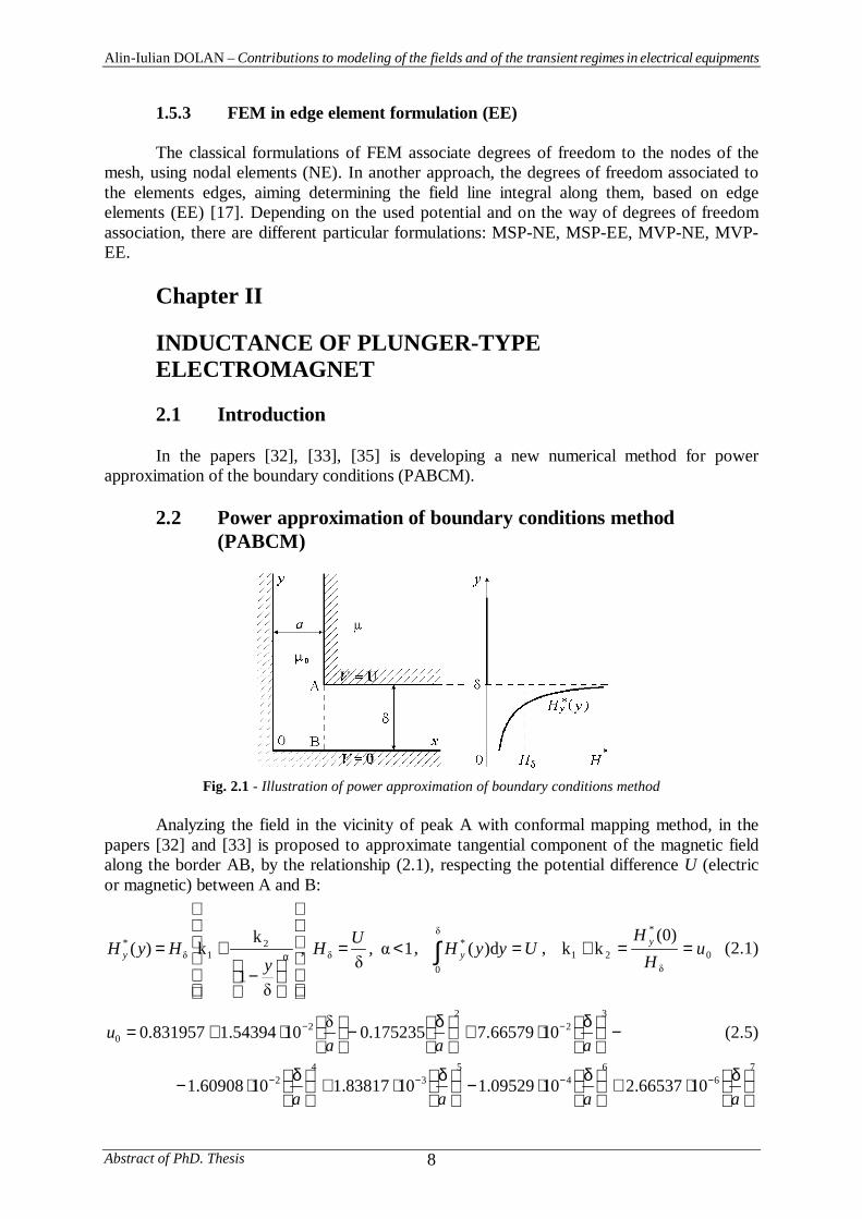
Fig. 2.1 - Illustration of power approximation of boundary conditions method
Analyzing the field in the vicinity of peak A with conformal mapping method, in thepapers [32] and [33] is proposed to approximate tangential component of the magnetic fieldalong the border AB, by the relationship (2.1), respecting the potential difference U (electricor magnetic) between A and B:
1,,1
kk)( 2
1* <=
−
+=α
UHy
HyH y , ∫ =0
* d)( UyyH y , 0
*
21
)0(kk u
HH y ==+ (2.1)
−
δ
⋅+
δ
−
⋅+= −−
32
22
0 1066579.7175235.01054394.1831957.0aaa
u (2.5)
76
64
53
42 1066537.21009529.11083817.11060908.1
δ
⋅+
δ
⋅−
δ
⋅+
δ
⋅− −−−−
aaaa
Alin-Iulian DOLAN – Contributions to modeling of the fields and of the transient regimes in electrical equipments
Abstract of PhD. Thesis9
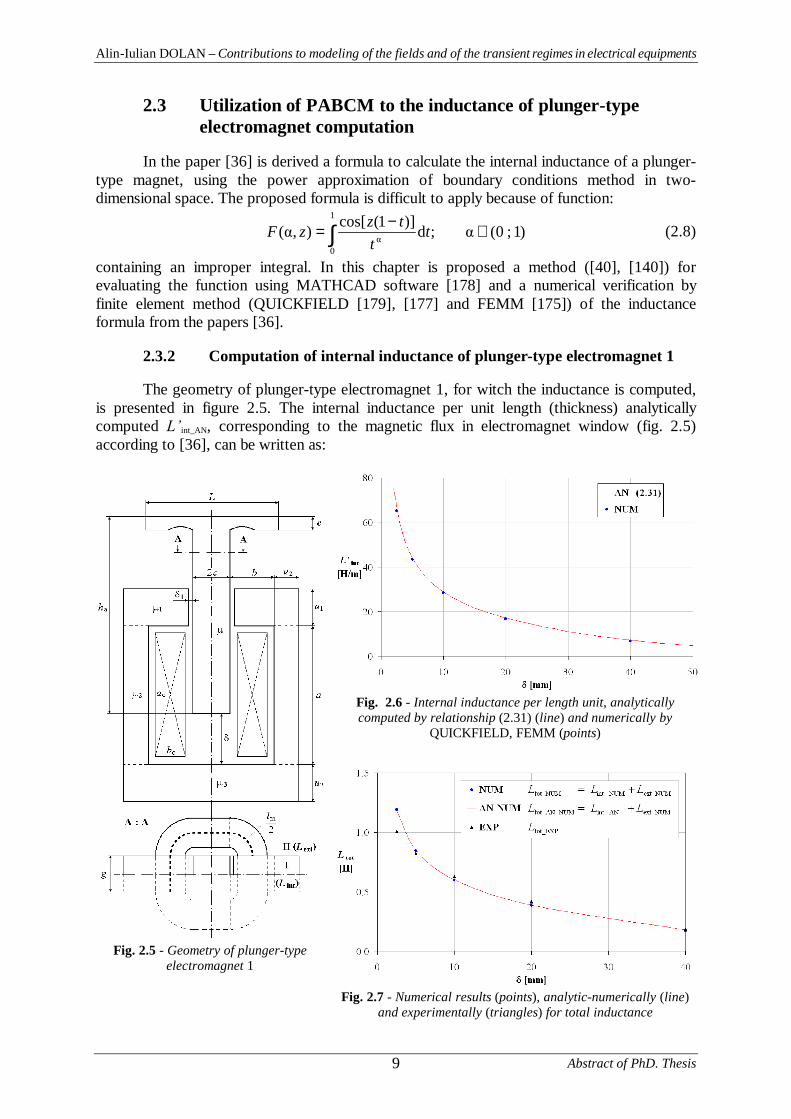
2.3 Utilization of PABCM to the inductance of plunger-typeelectromagnet computation
In the paper [36] is derived a formula to calculate the internal inductance of a plunger-type magnet, using the power approximation of boundary conditions method in two-dimensional space. The proposed formula is difficult to apply because of function:
∫ ∈−
=1
0
)1;0(;d)]1(cos[),( tt
tzzF (2.8)
containing an improper integral. In this chapter is proposed a method ([40], [140]) forevaluating the function using MATHCAD software [178] and a numerical verification byfinite element method (QUICKFIELD [179], [177] and FEMM [175]) of the inductanceformula from the papers [36].
2.3.2 Computation of internal inductance of plunger-type electromagnet 1
The geometry of plunger-type electromagnet 1, for witch the inductance is computed,is presented in figure 2.5. The internal inductance per unit length (thickness) analyticallycomputed int_AN, corresponding to the magnetic flux in electromagnet window (fig. 2.5)according to [36], can be written as:
Fig. 2.6 - Internal inductance per length unit, analyticallycomputed by relationship (2.31) (line) and numerically by
QUICKFIELD, FEMM (points)
Fig. 2.5 - Geometry of plunger-typeelectromagnet 1
Fig. 2.7 - Numerical results (points), analytic-numerically (line)and experimentally (triangles) for total inductance
Alin-Iulian DOLAN – Contributions to modeling of the fields and of the transient regimes in electrical equipments
Abstract of PhD. Thesis 10
+−
+++=′
abbbaabbaacGwL
624
22
22
e
11
e
20int_AN (2.31)
In formula (2.31) the cross section of the coil is considered having the window size:ac a, bc b.
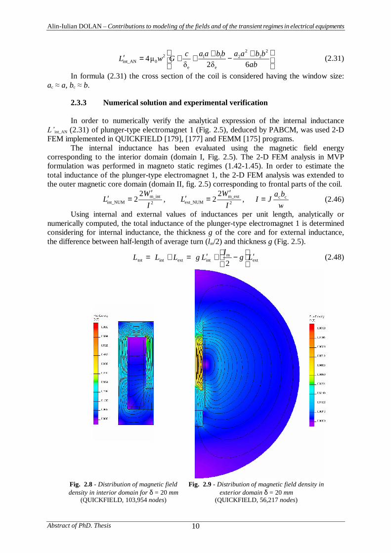
2.3.3 Numerical solution and experimental verification
In order to numerically verify the analytical expression of the internal inductanceint_AN (2.31) of plunger-type electromagnet 1 (Fig. 2.5), deduced by PABCM, was used 2-D
FEM implemented in QUICKFIELD [179], [177] and FEMM [175] programs.The internal inductance has been evaluated using the magnetic field energy
corresponding to the interior domain (domain I, Fig. 2.5). The 2-D FEM analysis in MVPformulation was performed in magneto static regimes (1.42-1.45). In order to estimate thetotal inductance of the plunger-type electromagnet 1, the 2-D FEM analysis was extended tothe outer magnetic core domain (domain II, fig. 2.5) corresponding to frontal parts of the coil.
2m_int
int_NUM
22
IW
L′
=′ , 2m_ext
ext_NUM
22
IW
L′
=′ ,wbaJI cc= (2.46)
Using internal and external values of inductances per unit length, analytically ornumerically computed, the total inductance of the plunger-type electromagnet 1 is determinedconsidering for internal inductance, the thickness g of the core and for external inductance,the difference between half-length of average turn (lm/2) and thickness g (Fig. 2.5).
extm
intextinttot 2LglLgLLL ′
−+′=+= (2.48)
Fig. 2.8 - Distribution of magnetic fielddensity in interior domain for δ = 20 mm
(QUICKFIELD, 103,954 nodes)
Fig. 2.9 - Distribution of magnetic field density inexterior domain δ = 20 mm
(QUICKFIELD, 56,217 nodes)
Alin-Iulian DOLAN – Contributions to modeling of the fields and of the transient regimes in electrical equipments
Abstract of PhD. Thesis11
Chapter III
STATIC CHARACTERISTIC OF A PLUNGER-TYPEELECTROMAGNET
3.2 Numerical computation of electromagnetic forces
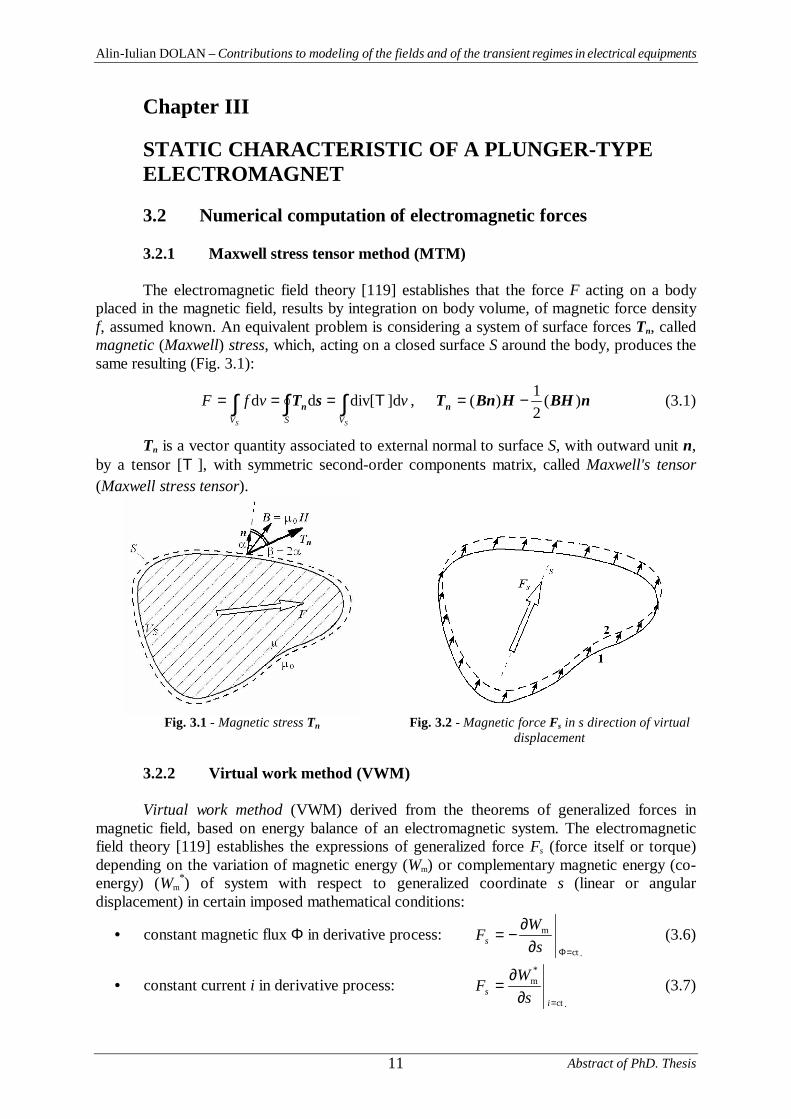
3.2.1 Maxwell stress tensor method (MTM)
The electromagnetic field theory [119] establishes that the force F acting on a bodyplaced in the magnetic field, results by integration on body volume, of magnetic force densityf, assumed known. An equivalent problem is considering a system of surface forces Tn, calledmagnetic (Maxwell) stress, which, acting on a closed surface S around the body, produces thesame resulting (Fig. 3.1):
∫∫∫ ===SS VSV
vvfF ]ddiv[dd TsTn , nBHHBnTn )(21)( −= (3.1)
Tn is a vector quantity associated to external normal to surface S, with outward unit n,by a tensor [T ], with symmetric second-order components matrix, called Maxwell's tensor(Maxwell stress tensor).
Fig. 3.1 - Magnetic stress Tn Fig. 3.2 - Magnetic force Fs in s direction of virtualdisplacement
3.2.2 Virtual work method (VWM)
Virtual work method (VWM) derived from the theorems of generalized forces inmagnetic field, based on energy balance of an electromagnetic system. The electromagneticfield theory [119] establishes the expressions of generalized force Fs (force itself or torque)depending on the variation of magnetic energy (Wm) or complementary magnetic energy (co-energy) (Wm
*) of system with respect to generalized coordinate s (linear or angulardisplacement) in certain imposed mathematical conditions:
• constant magnetic flux Φ in derivative process:.ct
m
=Φ∂∂
−=s
WFs (3.6)
• constant current i in derivative process:.ct
*m
=∂∂
=i
s sWF (3.7)
Alin-Iulian DOLAN – Contributions to modeling of the fields and of the transient regimes in electrical equipments
Abstract of PhD. Thesis 12
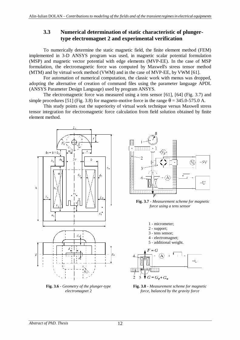
3.3 Numerical determination of static characteristic of plunger-type electromagnet 2 and experimental verification
To numerically determine the static magnetic field, the finite element method (FEM)implemented in 3-D ANSYS program was used, in magnetic scalar potential formulation(MSP) and magnetic vector potential with edge elements (MVP-EE). In the case of MSPformulation, the electromagnetic force was computed by Maxwell's stress tensor method(MTM) and by virtual work method (VWM) and in the case of MVP-EE, by VWM [61].
For automation of numerical computation, the classic work with menus was dropped,adopting the alternative of creation of command files using the parameter language APDL(ANSYS Parameter Design Language) used by program ANSYS.
The electromagnetic force was measured using a tens sensor [61], [64] (Fig. 3.7) andsimple procedures [51] (Fig. 3.8) for magneto-motive force in the range θ = 345.0-575.0 A.
This study points out the superiority of virtual work technique versus Maxwell stresstensor integration for electromagnetic force calculation from field solution obtained by finiteelement method.
Fig. 3.7 - Measurement scheme for magneticforce using a tens sensor
1 - micrometer;2 - support;3 - tens sensor;4 - electromagnet;5 - additional weight.
Fig. 3.6 - Geometry of the plunger-typeelectromagnet 2
Fig. 3.8 - Measurement scheme for magneticforce, balanced by the gravity force
Alin-Iulian DOLAN – Contributions to modeling of the fields and of the transient regimes in electrical equipments
Abstract of PhD. Thesis13
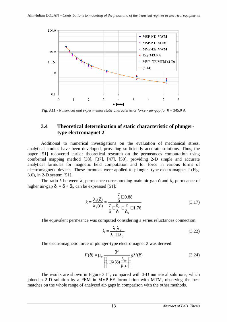
Fig. 3.11 - Numerical and experimental static characteristics force - air-gap for θ = 345.0 A
3.4 Theoretical determination of static characteristic of plunger-type electromagnet 2
Additional to numerical investigations on the evaluation of mechanical stress,analytical studies have been developed, providing sufficiently accurate solutions. Thus, thepaper [51] recovered earlier theoretical research on the permeances computation usingconformal mapping method [38], [37], [47], [50], providing 2-D simple and accurateanalytical formulas for magnetic field computation and for force in various forms ofelectromagnetic devices. These formulas were applied to plunger- type electromagnet 2 (Fig.3.6), in 2-D system [51].
The ratio k between λ1 permeance corresponding main air-gap δ and λ2 permeance ofhigher air-gap δ3 = δ + δ2, can be expressed [51]:
76.1
88.0
)()(
31
22
1
+δ
+δ
+δ
+δ≈
δλδλ
= thc
c
k (3.17)
The equivalent permeance was computed considering a series reluctances connection:
21
21
λ+λλλ
=λ (3.22)
The electromagnetic force of plunger-type electromagnet 2 was derived:
)(')(1
)(
r
Fe
2
0 δλ
µ
δλ+
θµ=δ g
cL
F (3.24)
The results are shown in Figure 3.11, compared with 3-D numerical solutions, whichjoined a 2-D solution by a FEM in MVP-EE formulation with MTM, observing the bestmatches on the whole range of analyzed air-gaps in comparison with the other methods.
Alin-Iulian DOLAN – Contributions to modeling of the fields and of the transient regimes in electrical equipments
Abstract of PhD. Thesis 14
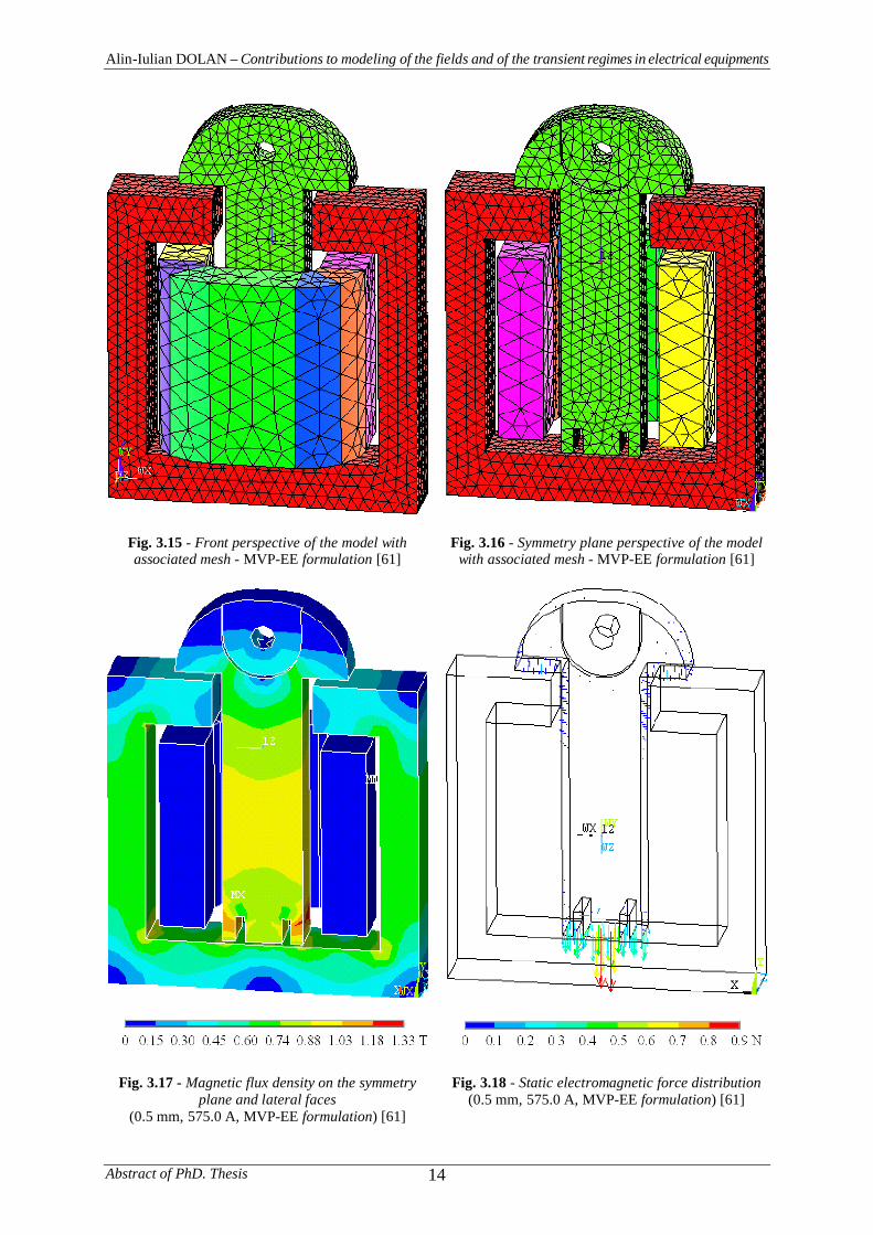
Fig. 3.15 - Front perspective of the model withassociated mesh - MVP-EE formulation [61]
Fig. 3.16 - Symmetry plane perspective of the modelwith associated mesh - MVP-EE formulation [61]
Fig. 3.17 - Magnetic flux density on the symmetryplane and lateral faces
(0.5 mm, 575.0 A, MVP-EE formulation) [61]
Fig. 3.18 - Static electromagnetic force distribution(0.5 mm, 575.0 A, MVP-EE formulation) [61]
Alin-Iulian DOLAN – Contributions to modeling of the fields and of the transient regimes in electrical equipments
Abstract of PhD. Thesis15
Chapter IV
LEAKAGE MAGNETIC FIELD AND MODELINGLIGHTNING SURGES IN POWER MULTI-WINDINGAUTOTRANSFORMER
4.3 Impedance voltage of the power multi-winding autotransformer
The power multi-winding three-phase autotransformer under investigation has ratedpowers of 400/400/80 MVA for voltage levels of 400/231/22 kV.
Let w1, w2, w3 be the numbers of turns of the three principal windings of powerautotransformer: primary, secondary and tertiary winding. The secondary winding isconnected to the median (principal) tapping of the regulating winding, so that the phasesecondary voltage for principal and marginal tappings is:
21
2r1phr2
2
R2
phr2ph2 3,2
wwwUU
w
wwUU
+=
α+⋅= (4.22)
where U1r is the primary rating line voltage and α is a coefficient depending on the tappingposition of regulating winding, -1 α 1, being zero for principal tapping.
4.3.1 Primary-secondary windings pair
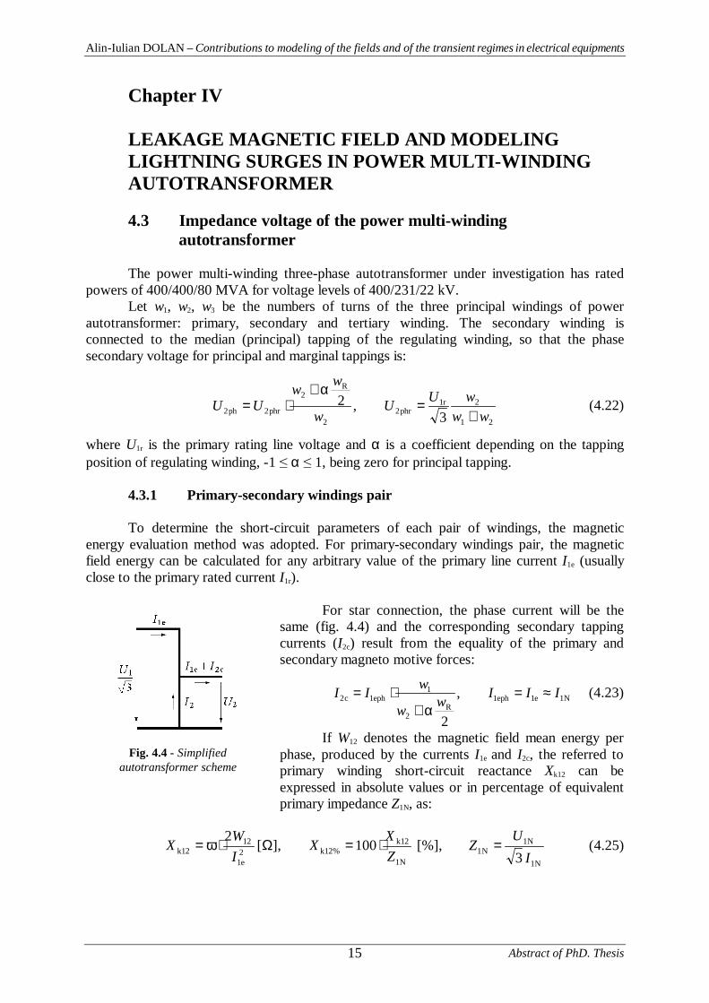
To determine the short-circuit parameters of each pair of windings, the magneticenergy evaluation method was adopted. For primary-secondary windings pair, the magneticfield energy can be calculated for any arbitrary value of the primary line current I1e (usuallyclose to the primary rated current I1r).
For star connection, the phase current will be thesame (fig. 4.4) and the corresponding secondary tappingcurrents (I2c) result from the equality of the primary andsecondary magneto motive forces:
N1e1eph1R
2
1eph1c2 ,
2
IIIww
wII ≈=α+
⋅= (4.23)
If W12 denotes the magnetic field mean energy perphase, produced by the currents I1e and I2c, the referred toprimary winding short-circuit reactance Xk12 can beexpressed in absolute values or in percentage of equivalentprimary impedance Z1N, as:
N1
N1N1
N1
12k%12k2
e1
1212k 3
[%],100],[2I
UZ
ZXX
IWX =⋅=Ω⋅ω= (4.25)
Fig. 4.4 - Simplifiedautotransformer scheme
Alin-Iulian DOLAN – Contributions to modeling of the fields and of the transient regimes in electrical equipments
Abstract of PhD. Thesis 16
4.4 Numerical evaluation of the magnetic field energy and of the short-circuit reactance with FEMM program
4.4.1 2-D model and the boundary conditions
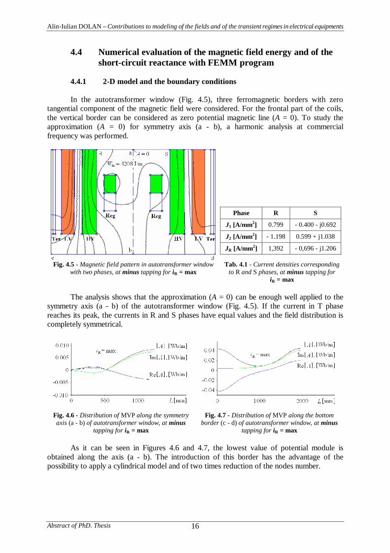
In the autotransformer window (Fig. 4.5), three ferromagnetic borders with zerotangential component of the magnetic field were considered. For the frontal part of the coils,the vertical border can be considered as zero potential magnetic line (A = 0). To study theapproximation (A = 0) for symmetry axis (a - b), a harmonic analysis at commercialfrequency was performed.
Phase R S
J1 [A/mm2] 0.799 - 0.400 - j0.692
J2 [A/mm2] - 1.198 0.599 + j1.038
JR [A/mm2] 1,392 - 0,696 - j1.206
Fig. 4.5 - Magnetic field pattern in autotransformer windowwith two phases, at minus tapping for iR = max
Tab. 4.1 - Current densities correspondingto R and S phases, at minus tapping for
iR = max
The analysis shows that the approximation (A = 0) can be enough well applied to thesymmetry axis (a - b) of the autotransformer window (Fig. 4.5). If the current in T phasereaches its peak, the currents in R and S phases have equal values and the field distribution iscompletely symmetrical.
Fig. 4.6 - Distribution of MVP along the symmetryaxis (a - b) of autotransformer window, at minus
tapping for iR = max
Fig. 4.7 - Distribution of MVP along the bottomborder (c - d) of autotransformer window, at minus
tapping for iR = max
As it can be seen in Figures 4.6 and 4.7, the lowest value of potential module isobtained along the axis (a - b). The introduction of this border has the advantage of thepossibility to apply a cylindrical model and of two times reduction of the nodes number.
Alin-Iulian DOLAN – Contributions to modeling of the fields and of the transient regimes in electrical equipments
Abstract of PhD. Thesis17
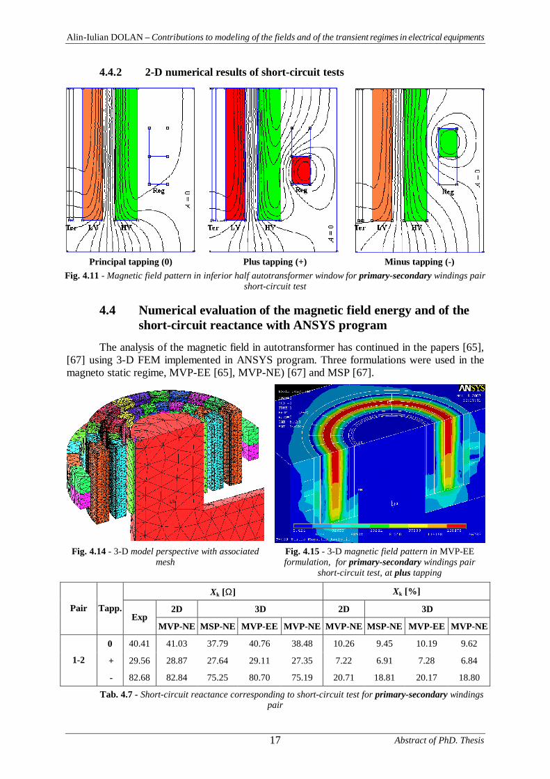
4.4.2 2-D numerical results of short-circuit tests
Principal tapping (0) Plus tapping (+) Minus tapping (-)Fig. 4.11 - Magnetic field pattern in inferior half autotransformer window for primary-secondary windings pair
short-circuit test
4.4 Numerical evaluation of the magnetic field energy and of the short-circuit reactance with ANSYS program
The analysis of the magnetic field in autotransformer has continued in the papers [65],[67] using 3-D FEM implemented in ANSYS program. Three formulations were used in themagneto static regime, MVP-EE [65], MVP-NE) [67] and MSP [67].
Fig. 4.14 - 3-D model perspective with associatedmesh
Fig. 4.15 - 3-D magnetic field pattern in MVP-EEformulation, for primary-secondary windings pair
short-circuit test, at plus tapping
Xk [Ω] Xk [%]
2D 3D 2D 3DPair Tapp.Exp
MVP-NE MSP-NE MVP-EE MVP-NE MVP-NE MSP-NE MVP-EE MVP-NE
0 40.41 41.03 37.79 40.76 38.48 10.26 9.45 10.19 9.62
+ 29.56 28.87 27.64 29.11 27.35 7.22 6.91 7.28 6.841-2
- 82.68 82.84 75.25 80.70 75.19 20.71 18.81 20.17 18.80
Tab. 4.7 - Short-circuit reactance corresponding to short-circuit test for primary-secondary windingspair
Alin-Iulian DOLAN – Contributions to modeling of the fields and of the transient regimes in electrical equipments
Abstract of PhD. Thesis 18
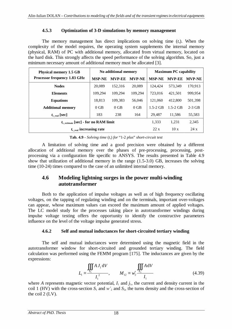
4.5.3 Optimization of 3-D simulations by memory management
The memory management has direct implications on solving time (ts). When thecomplexity of the model requires, the operating system supplements the internal memory(physical, RAM) of PC with additional memory, allocated from virtual memory, located onthe hard disk. This strongly affects the speed performance of the solving algorithm. So, just aminimum necessary amount of additional memory must be allocated [3].
No additional memory Maximum PC capabilityPhysical memory 1.5 GBProcessor frequency 1.83 GHz MSP-NE MVP-EE MVP-NE MSP-NE MVP-EE MVP-NE
Nodes 20,089 152,316 20,089 124,424 573,349 170,913
Elements 109,294 109,294 109,294 723,016 421,501 999,954
Equations 18,813 109,383 56,046 121,060 412,800 501,398
Additional memory 0 GB 0 GB 0 GB 1.5-2 GB 1.5-2 GB 2-3 GB
ts_real [sec] 183 238 164 29,487 11,586 55,583
ts_estimate [sec] - for no RAM limit 1,333 1,231 2,345
ts_real increasing rate 22 x 10 x 24 x
Tab. 4.9 - Solving time (ts) for “1-2 plus” short-circuit test
A limitation of solving time and a good precision were obtained by a differentallocation of additional memory over the phases of pre-processing, processing, post-processing via a configuration file specific to ANSYS. The results presented in Table 4.9show that utilization of additional memory in the range (1.5-3.0) GB, increases the solvingtime (10-24) times compared to the case of an unlimited internal memory.
4.6 Modeling lightning surges in the power multi-windingautotransformer
Both to the application of impulse voltages as well as of high frequency oscillatingvoltages, on the tapping of regulating winding and on the terminals, important over-voltagescan appear, whose maximum values can exceed the maximum amount of applied voltages.The LC model study for the processes taking place in autotransformer windings duringimpulse voltage testing offers the opportunity to identify the constructive parametersinfluence on the level of the voltage impulse generated stress.
4.6.2 Self and mutual inductances for short-circuited tertiary winding
The self and mutual inductances were determined using the magnetic field in theautotransformer window for short-circuited and grounded tertiary winding. The fieldcalculation was performed using the FEMM program [175]. The inductances are given by theexpressions:
1
S2122
1
S1
121
d,
d
I
VAwM
I
VJAL
∫∫∫∫∫∫′== (4.39)
where A represents magnetic vector potential, I1 and j1, the current and density current in thecoil 1 (HV) with the cross-section S1 and 2 and S2, the turns density and the cross-section ofthe coil 2 (LV).
Alin-Iulian DOLAN – Contributions to modeling of the fields and of the transient regimes in electrical equipments
Abstract of PhD. Thesis19
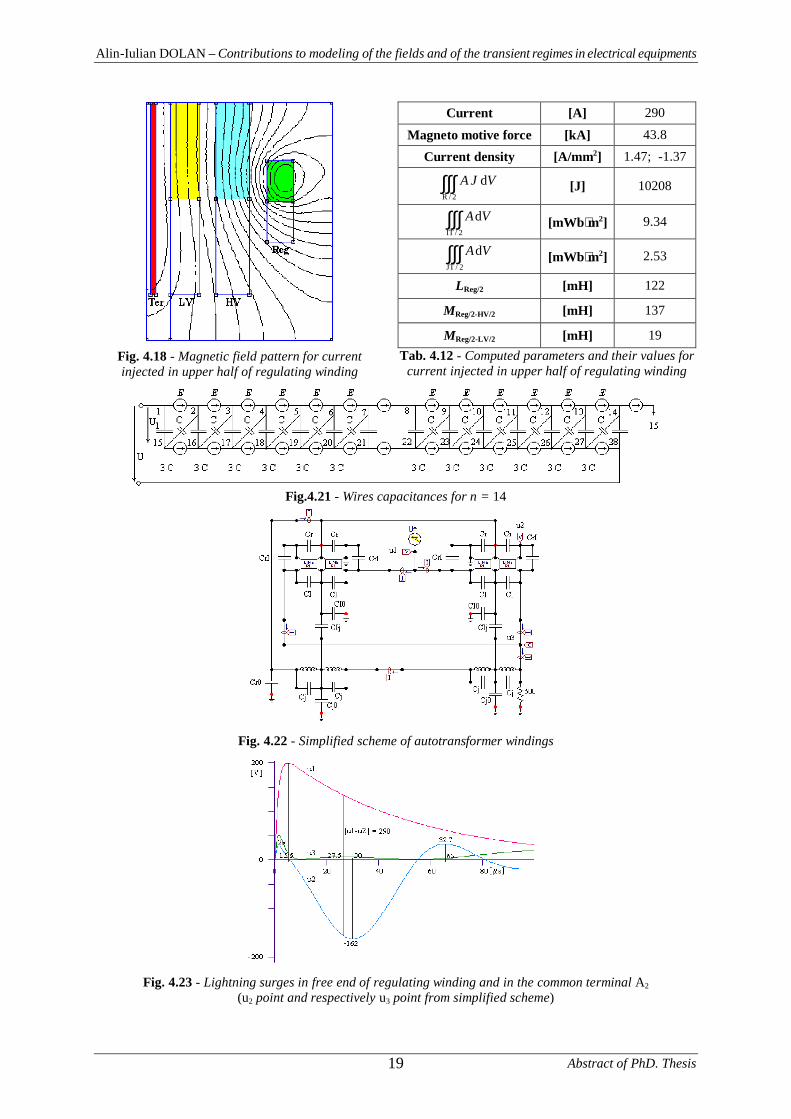
Fig. 4.18 - Magnetic field pattern for currentinjected in upper half of regulating winding
Current [A] 290
Magneto motive force [kA] 43.8
Current density [A/mm2] 1.47; -1.37
∫∫∫2/R
dVJA [J] 10208
∫∫∫2/IT
dVA [mWb⋅m2] 9.34
∫∫∫2/JT
dVA [mWb⋅m2] 2.53
LReg/2 [mH] 122
MReg/2-HV/2 [mH] 137
MReg/2-LV/2 [mH] 19Tab. 4.12 - Computed parameters and their values for
current injected in upper half of regulating winding
Fig.4.21 - Wires capacitances for n = 14
Fig. 4.22 - Simplified scheme of autotransformer windings
Fig. 4.23 - Lightning surges in free end of regulating winding and in the common terminal A2
(u2 point and respectively u3 point from simplified scheme)
Alin-Iulian DOLAN – Contributions to modeling of the fields and of the transient regimes in electrical equipments
Abstract of PhD. Thesis 20
Chapter V
NUMERICAL SIMULATION OF TRANSIENTELECTRIC AND MAGNETIC FIELDS INRECTANGULAR SOLID BUS BARS
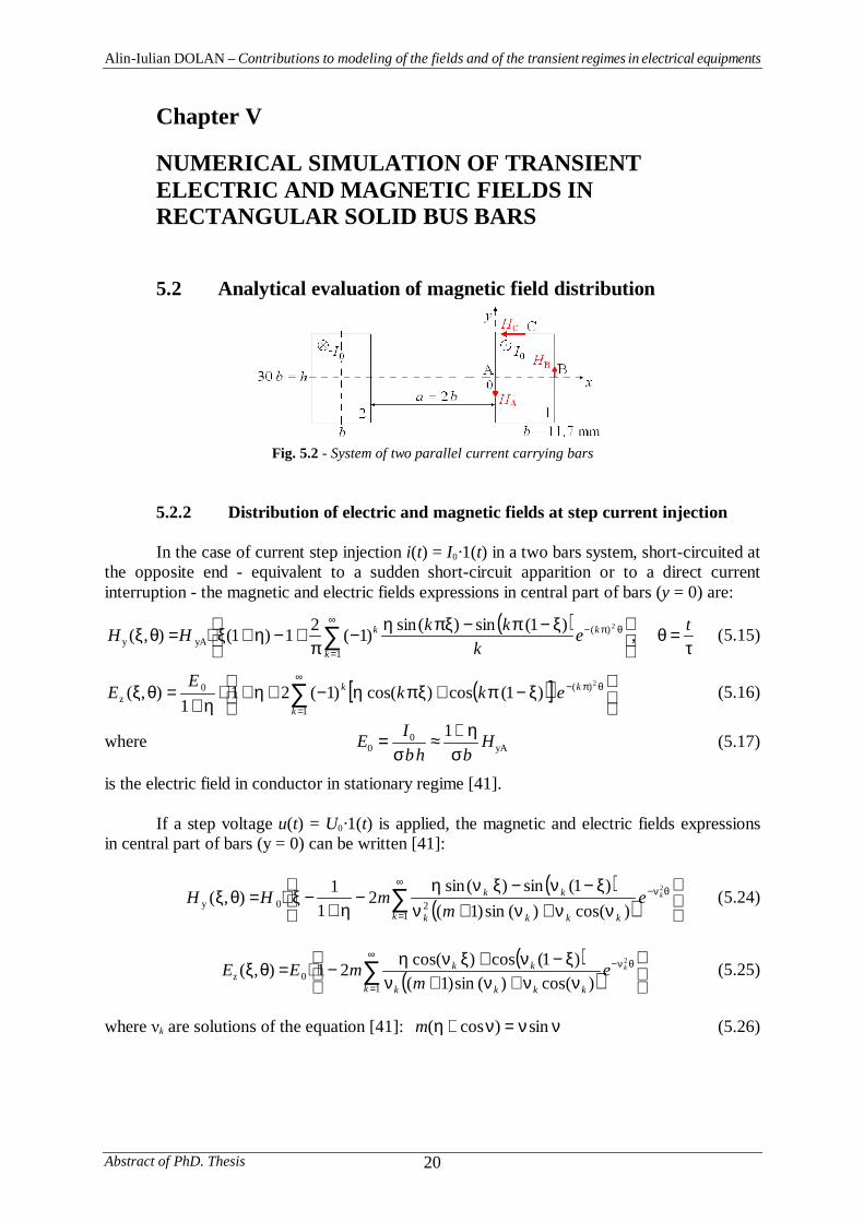
5.2 Analytical evaluation of magnetic field distribution
Fig. 5.2 - System of two parallel current carrying bars
5.2.2 Distribution of electric and magnetic fields at step current injection
In the case of current step injection i(t) = I0·1(t) in a two bars system, short-circuited atthe opposite end - equivalent to a sudden short-circuit apparition or to a direct currentinterruption - the magnetic and electric fields expressions in central part of bars (y = 0) are:
( )τ
=θ
ξ−π−ξπη−
π+−η+ξ⋅=θξ ∑
∞
=
θπ− tek
kkHHk
kk ,)1(sin)(sin)1(21)1(),(1
)(yAy
2
(5.15)
( )[ ]
ξ−π+ξπη−+η+⋅
η+=θξ ∑
∞
=
θπ−
1
)(0z
2
)1(cos)(cos)1(211
),(k
kk ekkE
E (5.16)
where yA0
01 H
bhbIE
ση+
≈σ
= (5.17)
is the electric field in conductor in stationary regime [41].
If a step voltage u(t) = U0·1(t) is applied, the magnetic and electric fields expressionsin central part of bars (y = 0) can be written [41]:
( )( )
νν+ν+ν
ξ−ν−ξνη−
η+−ξ⋅=θξ ∑
∞
=
θν−
120y
2
)(cos)(sin)1()1(sin)(sin
21
1),(k kkkk
kk kem
mHH (5.24)
( )( )
νν+ν+ν
ξ−ν+ξνη−⋅=θξ ∑
∞
=
θν−
10z
2
)(cos)(sin)1()1(cos)(cos21),(
k kkkk
kk kem
mEE (5.25)
where k are solutions of the equation [41]: νν=ν+η sin)cos(m (5.26)
Alin-Iulian DOLAN – Contributions to modeling of the fields and of the transient regimes in electrical equipments
Abstract of PhD. Thesis21
5.3 Numerical simulation of transient electric and magnetic fieldsin the system of rectangular bus bars
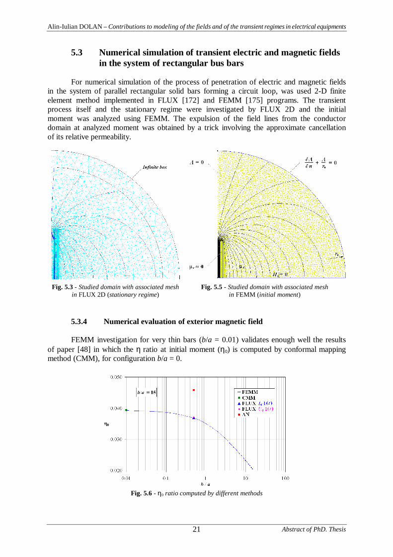
For numerical simulation of the process of penetration of electric and magnetic fieldsin the system of parallel rectangular solid bars forming a circuit loop, was used 2-D finiteelement method implemented in FLUX [172] and FEMM [175] programs. The transientprocess itself and the stationary regime were investigated by FLUX 2D and the initialmoment was analyzed using FEMM. The expulsion of the field lines from the conductordomain at analyzed moment was obtained by a trick involving the approximate cancellationof its relative permeability.
Fig. 5.3 - Studied domain with associated meshin FLUX 2D (stationary regime)
Fig. 5.5 - Studied domain with associated meshin FEMM (initial moment)
5.3.4 Numerical evaluation of exterior magnetic field
FEMM investigation for very thin bars (b/a = 0.01) validates enough well the resultsof paper [48] in which the η ratio at initial moment (η0) is computed by conformal mappingmethod (CMM), for configuration b/a = 0.
Fig. 5.6 - η0 ratio computed by different methods
Alin-Iulian DOLAN – Contributions to modeling of the fields and of the transient regimes in electrical equipments
Abstract of PhD. Thesis 22
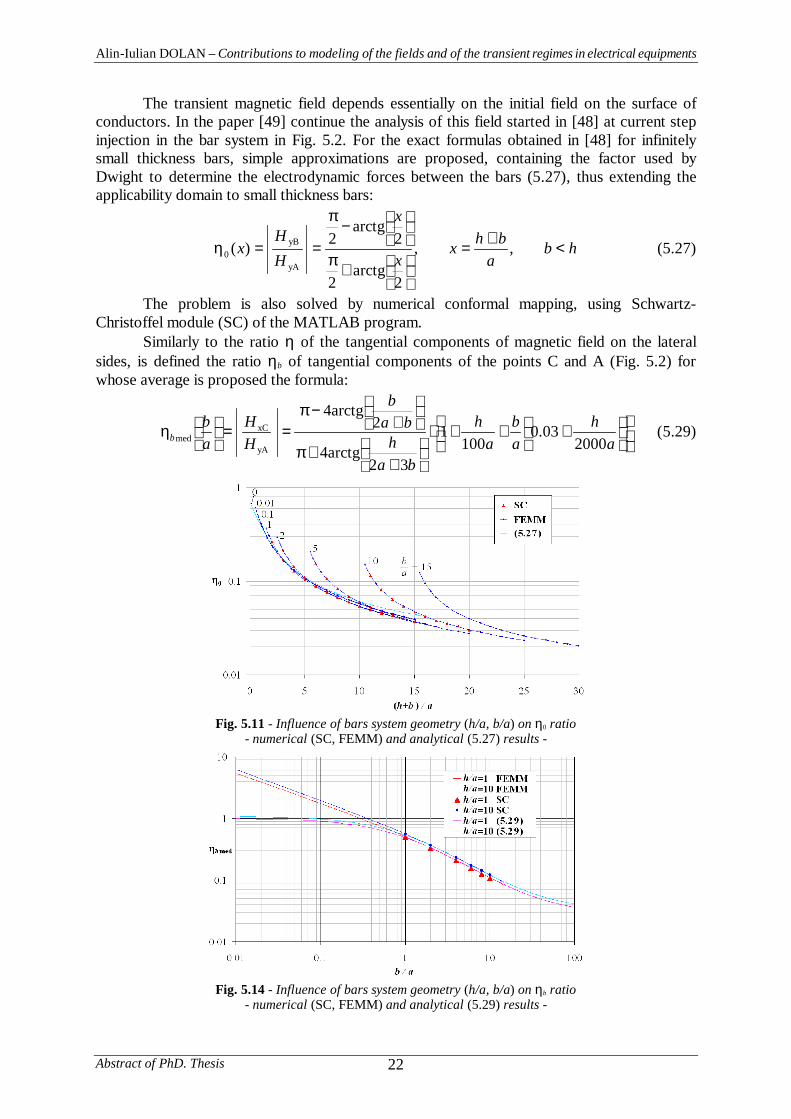
The transient magnetic field depends essentially on the initial field on the surface ofconductors. In the paper [49] continue the analysis of this field started in [48] at current stepinjection in the bar system in Fig. 5.2. For the exact formulas obtained in [48] for infinitelysmall thickness bars, simple approximations are proposed, containing the factor used byDwight to determine the electrodynamic forces between the bars (5.27), thus extending theapplicability domain to small thickness bars:
hba
bhxx
x
HH
x <+
=
+
π
−
π
==η ,,
2arctg
2
2arctg
2)(yA
yB0 (5.27)
The problem is also solved by numerical conformal mapping, using Schwartz-Christoffel module (SC) of the MATLAB program.
Similarly to the ratio η of the tangential components of magnetic field on the lateralsides, is defined the ratio ηb of tangential components of the points C and A (Fig. 5.2) forwhose average is proposed the formula:
+++⋅
++π
+−π
==
η
ah
ab
ah
bah
bab
HH
ab
b 200003.0
1001
32arctg4
2arctg4
yA
xCmed (5.29)
Fig. 5.11 - Influence of bars system geometry (h/a, b/a) on η0 ratio- numerical (SC, FEMM) and analytical (5.27) results -
Fig. 5.14 - Influence of bars system geometry (h/a, b/a) on ηb ratio- numerical (SC, FEMM) and analytical (5.29) results -
Alin-Iulian DOLAN – Contributions to modeling of the fields and of the transient regimes in electrical equipments
Abstract of PhD. Thesis23
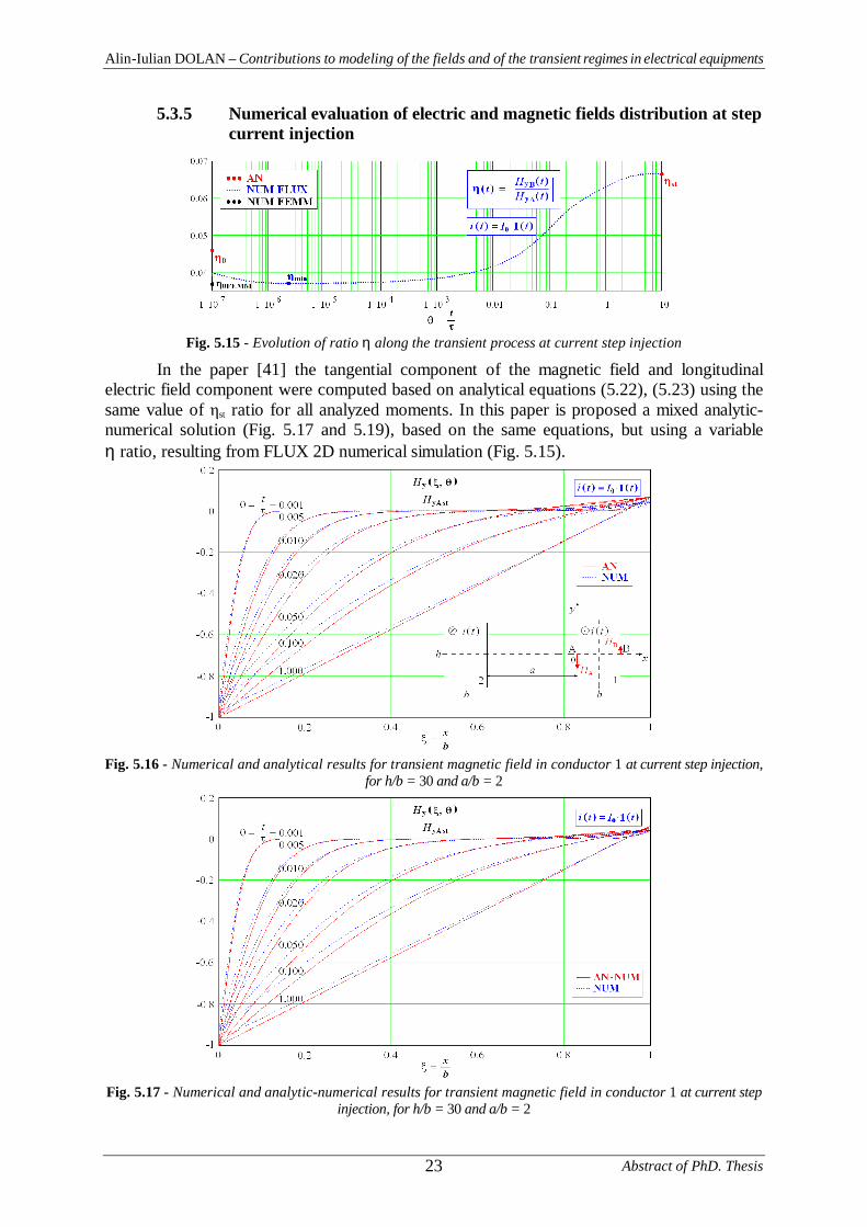
5.3.5 Numerical evaluation of electric and magnetic fields distribution at stepcurrent injection
Fig. 5.15 - Evolution of ratio η along the transient process at current step injection
In the paper [41] the tangential component of the magnetic field and longitudinalelectric field component were computed based on analytical equations (5.22), (5.23) using thesame value of st ratio for all analyzed moments. In this paper is proposed a mixed analytic-numerical solution (Fig. 5.17 and 5.19), based on the same equations, but using a variableη ratio, resulting from FLUX 2D numerical simulation (Fig. 5.15).
Fig. 5.16 - Numerical and analytical results for transient magnetic field in conductor 1 at current step injection,for h/b = 30 and a/b = 2
Fig. 5.17 - Numerical and analytic-numerical results for transient magnetic field in conductor 1 at current stepinjection, for h/b = 30 and a/b = 2
Alin-Iulian DOLAN – Contributions to modeling of the fields and of the transient regimes in electrical equipments
Abstract of PhD. Thesis 24
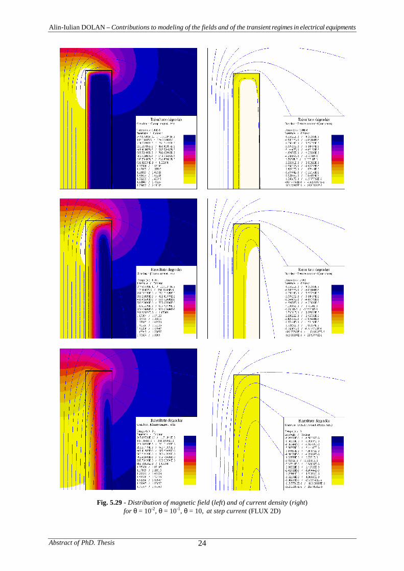
Fig. 5.29 - Distribution of magnetic field (left) and of current density (right)for θ = 10-2, θ = 10-1, θ = 10, at step current (FLUX 2D)
Alin-Iulian DOLAN – Contributions to modeling of the fields and of the transient regimes in electrical equipments
Abstract of PhD. Thesis25
Chapter VI
NUMERICAL DETERMINATION OF TRANSIENTPARAMETERS OF A SYSTEM OF RECTANGULARSOLID BUS BARS
6.1 Transient parameters of the linear electrical circuits
6.1.4 Transient parameters of a non-filiforme and with additional lossescircuit element
6.1.4.4 Integral relationships between instantaneous values of currents andvoltages
The integral equations of current and voltage (ε > 0, arbitrary little) for the non-filiforme circuit elements and with additional losses are respectively:
( ) ( ) ( ) ( )∫∫ε−
++ +ξξξ−
++=+ξξξ−+=tt
tuit
tltt
ilirtuitrtt
iltu0
0000
)(dd
ddd
dd)0()(d
dd
dd)0()( (6.70)
( ) ( ) ( ) ( )∫∫ε−
++ +ξξξ−
++=+ξξξ−+=tt
tiut
tctt
ucugtiutgtt
ucti0
0000
)(dd
ddd
dd)0()(d
dd
dd)0()( (6.71)
6.1.4.5 Experimental determination of transient parameters
At current step injection i(t) = 1(t), respectively, at voltage step application u(t) = 1(t),the relationships (6.70), (6.71) become :
)(d)(,d
)(d)(1)()()0()( 00
0 tltrttuttltrtrtltu
t
+=+⋅=+δ= ∫ε−
+ (6.80)
)(d)(,d
)(d)(1)()()0()( 00
0 tctgttittctgtgtcti
t
+=+⋅=+δ= ∫ε−
+ (6.81)
At current ramp injection i(t) = t·1(t), respectively, at voltage ramp applicationu(t) = t·1(t), the relationships (6.70), (6.71) become :
)()()0(d
)(d),(d)()(1)0()( 00
trtlttutltrttrtltu
t
+δ⋅=+⋅=+⋅= +ε−
+ ∫ (6.84)
)()()0(d
)(d),(d)()(1)0()( 00
tgtcttitctgttgtcti
t
+δ⋅=+⋅=+⋅= +ε−
+ ∫ (6.85)
The determination of transient resistance and conductance can be convenient inexperimental conditions of step signals application, when, for a capacitive element (l(0+) = 0)or inductive element (c(0+) = 0), these parameters are identified with the applied signals:
0),(1)()(1)()()()0()()(
>==+ =δ−=
tttittitutltutr (6.92)
0),(1)()(1)()()()0()()(
>==+ =δ−=
tttuttutitltitg (6.93)
Alin-Iulian DOLAN – Contributions to modeling of the fields and of the transient regimes in electrical equipments
Abstract of PhD. Thesis 26
6.2 Utilization of FLUX program in determination of transientparameters of the system of rectangular solid bus bars
6.2.2 Determination of transient resistance and inductance at step currentinjection
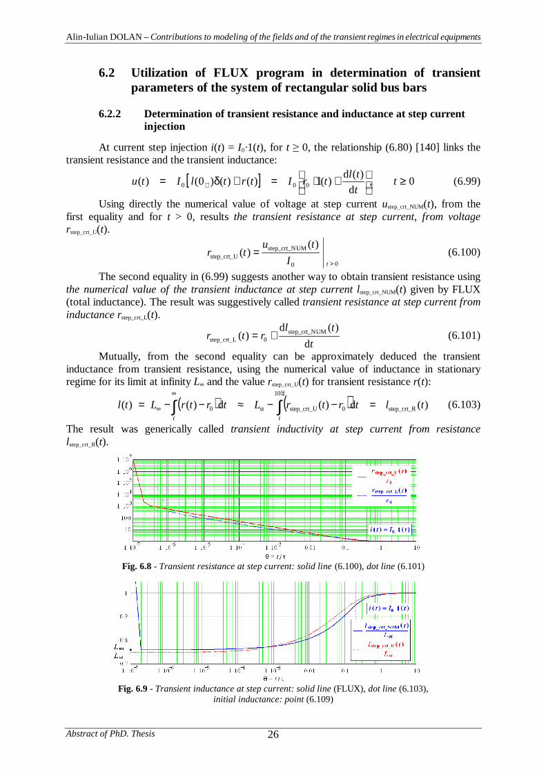
At current step injection i(t) = I0·1(t), for t 0, the relationship (6.80) [140] links thetransient resistance and the transient inductance:
[ ] 0,d
)(d)(1)()()0()( 000 ≥
+⋅=+δ= + t
ttltrItrtlItu (6.99)
Using directly the numerical value of voltage at step current ustep_crt_NUM(t), from thefirst equality and for t > 0, results the transient resistance at step current, from voltagerstep_crt_U(t).
00
UMstep_crt_Nstep_crt_U
)()(
>
=tI
tutr (6.100)
The second equality in (6.99) suggests another way to obtain transient resistance usingthe numerical value of the transient inductance at step current lstep_crt_NUM(t) given by FLUX(total inductance). The result was suggestively called transient resistance at step current frominductance rstep_crt_L(t).
ttl
rtrd
)(d)( UMstep_crt_N
0step_crt_L += (6.101)
Mutually, from the second equality can be approximately deduced the transientinductance from transient resistance, using the numerical value of inductance in stationaryregime for its limit at infinity L∞ and the value rstep_crt_U(t) for transient resistance r(t):
( ) ( ) )(d)(d)()( step_crt_R
10
0step_crt_Ust0 tltrtrLtrtrLtltt
=−−≈−−= ∫∫τ⋅∞
∞ (6.103)
The result was generically called transient inductivity at step current from resistancelstep_crt_R(t).
Fig. 6.8 - Transient resistance at step current: solid line (6.100), dot line (6.101)
Fig. 6.9 - Transient inductance at step current: solid line (FLUX), dot line (6.103),initial inductance: point (6.109)
Alin-Iulian DOLAN – Contributions to modeling of the fields and of the transient regimes in electrical equipments
Abstract of PhD. Thesis27
Chapter VII
ORIGINAL CONTRIBUTIONS AND CONCLUSIONS
Author's original contributions to modeling the fields and transient regimes inelectrical equipments are structured on the chapters.
In Chapter II is proposed an experimental and numerical verification of powerapproximation of boundary conditions method (PABCM) developed in [32], [33], [35] in theevaluation of total inductance of a plunger-type electromagnet (Fig. 2.5). The author'scontributions in this verification follow:
• Based on PABCM, in the paper [36], in the assumption of fitting coildimensions with electromagnet window, was derived an analytical expression of the internalinductance per unit length int_AN (2.31) (domain I, corresponding to the magnetic core withthickness g, Fig. 2.5) for 2-D case, which is difficult to apply because it contains an improperintegral F(α, z) (2.21). The author proposes its computation using MATHCAD program[178];
• To evaluate the total inductance of the electromagnet Ltot were taken intoaccount two components: internal inductance Lint (domain I, Fig. 2.5) obtained by multiplyingthe internal inductance per unit length int by the thickness g of magnetic core and externalinductance Lext (domain II, outer magnetic core domain, corresponding to frontal parts of thecoil, Fig. 2.5) obtained by multiplying the external inductance per unit length ext bydifference between half-length of average turn (lm / 2) and the thickness g (Fig. 2.5 ).
• The two components were numerically evaluated based on magnetic energystored in corresponding domains, determined by FEM in magneto static regime implementedin QUICKFIELD [179] [177] and FEMM [175] programs. The average relative error ofnumerical solution versus analytical solution for the internal inductance per unit length int is2.47%, validating the analytical formula (2.31) to calculate the internal inductance.
• The analytical and numerical evaluation of internal inductance and numericalevaluation of the external inductance by two programs for 2-D FEM analysis led to twosolutions for the total inductance, one purely numerical witch presents very small averagedeviations versus experimental data (0.78%) and an other solution, analytical-numerical, witherrors of 1.67%. The accuracy of the results containing the analytical formula (2.31) onceagain confirms its accuracy.
• It were justified some results errors being made useful recommendations. Thelarge differences between experimental data and those calculated for small air-gaps can beexplained by distorted form of the plunger, whose sides are not flat as in Figure 2.5. Anotherpossible errors source can be the simplified geometry of "I" form of plunger versus "T" realform (Fig. 2.5). The analytical and numerical solutions accuracy can be improved byremoving the simplified geometric assumptions and, concerning only numerical solution, by3-D approach for exact geometric configuration description.
Chapter III presents the results of theoretical and experimental investigations on aplunger-type electromagnet to test the effectiveness of analytical and numerical methods forcalculating the developed force.
Earlier theoretical research [38], [37], [47], [50] using conformal mapping method(CMM) provided simple and precise analytical formulas for 2-D permeances calculation,useful for obtaining of an analytical expression for the electromagnetic force (3.19). Theauthor has created 3-D numerical models of a plunger-type electromagnet (Fig. 3.6) and
Alin-Iulian DOLAN – Contributions to modeling of the fields and of the transient regimes in electrical equipments
Abstract of PhD. Thesis 28
experimental determinations were performed to validate the own results and the analyticalones. The contributions in these investigations are presented below:
• The numerical method used for analysis is the finite element method (FEM),which is most suitable for the techniques of determining the force. Two formulations of 3-DFEM in magneto static regime were adopted: the magnetic scalar potential formulation withnodal elements (MSP-NE) and the magnetic vector potential formulation with edge elements(MVP-EE). Two classical techniques to obtain the global force from the field solution werechosen: the Maxwell stress tensor method (MTM) and the virtual work method (VWM). Theadopted formulations in conjunction with one or both techniques, implemented in theANSYS program [171] led to obtain three numerical solutions for static characteristic ofplunger-type electromagnet: MSP-NE MTM, MSP-NE VWM and MVP-EE VWM.
• To automate the calculation, the classic work with menus was dropped,adopting the alternative of creation of command files using the parameter language APDL ofANSYS program and to reduce the execution time of these files the batch mode was adoptedminimizing the required hardware resources.
• The electromagnetic force was experimentally determined for a particularrange of air-gap, using a tens sensor for smaller air-gaps and simple procedures of gravityplunger determination, applied to higher air-gaps, when the saturation effect is negligible.
• The obtaining of parallel results (Fig. 3.9) allowed the comparison of themethods based on measurements. Average relative error of analysis versus experimental datashows that the most accurate solution is given by MSP VWM, with 0.08%, followed byMVP-EE VWM formulation with 6.17%, the least precise formulation being obtained byMSP MTM, with 20.27% (Fig. 3.10). This study pointed out the superiority of virtual worktechnique compared to Maxwell stress tensor integration for electromagnetic forcecalculation from 3-D FEM field solution. The magnetic vector potential formulation withnodal elements (MVP-NE) was also used in conjunction with both techniques MTM andVWM, but the results have proved wrong. However, its 2-D implementation in FEMMprogram [175] in conjunction with MTM is in good agreement with experimental data (Fig.3.9) (average relative error of 4.00%). Also, the average relative error of the force obtainedwith the analytical formula (3.24) compared to measurements is of 3.89%, witch is itsvalidation (Fig. 3.9).
• Another criterion of comparison between methods was the solutionconvergence versus the number of used finite elements and the size of elements in air-gapthat have great influence on force accuracy. The results show a faster convergence of VWMcompared to MTM requiring a finer mesh.
In Chapter IV has been studied the leakage magnetic flux in a three phase powerautotransformer 400/400/80 MVA, 400/231/22 kV, with primary, secondary, tertiary andregulating windings, with multiple tappings, resulting 2-D and 3-D numerical models.
The autotransformer behavior at the application of lightning surges was also analyzed,aiming the over voltages level on the tappings of regulating winding. The considerable size of3-D numerical simulations led to investigations for their optimization, concerning the solvingtime reduction and accuracy increasing, up to hardware resources. The author's contributionsin these studies are pointed out below:
• Since the impedance voltage for secondary tapping of regulating winding cannot be evaluated using simple formulas, derived under the assumption of straight lines ofmagnetic flux, the author has considered the real pattern of magnetic field obtained by FEM.Thus, two numerical models were obtained, a 2-D model using FEMM program [175] and a3-D one using ANSYS program [171], assuming a static magnetic regime which
Alin-Iulian DOLAN – Contributions to modeling of the fields and of the transient regimes in electrical equipments
Abstract of PhD. Thesis29
approximates enough well the regime of commercial frequency, taking into account the smallsections of the conductors.
• To obtain the 2-D model, a preliminary study for necessary boundaryconditions was performed. For the frontal part of the coils, on the vertical border, a small skindepth should be considered, due to aluminum or copper screen of the autotransformer tank.However, at commercial frequency, the magnetic field determined in these conditions ispractically identical to the static field corresponding to zero frequency and the vertical frontalborder can be considered as a zero magnetic potential line (A = 0).
• For the other borders, a FEMM analysis was performed in harmonic regime atcommercial frequency, at two moments delayed by a quarter of period, aiming the magneticvector potential (MVP) values along the symmetry line of the autotransformer window,compared to its values on the bottom border of the window (Fig. 4.5, 4.10). The results hadshowed extremely low values (Fig. 4.6-4.9), suggesting consideration of symmetry lines ofthe windows as zero potential magnetic flux lines.
• The last approximation is also sustained by the equality of magnetic fieldenergies per unit length, calculated at the two moments.
• Another confirmation is given by the recalculation of the energy, applying theapproximation to the symmetry axis, which proved to be only 0.50% lower.
• Considering the symmetry lines of the autotransformer windows as zeromagnetic potential flux lines, like the flux lines from the frontal parts of windings, in thevicinity of the screened tank, has allowed the use of a cylindrical model, very economical interms of numerical computation. The FEMM axi-symmetric solution in magneto staticregime for the short-circuit reactance corresponding to principal and marginal tappings ofregulating winding, agree with the experimental data with errors less than 3.00% (Table 4.8).
• The field problem was solved in 3-D using three formulations of FEM: MVP-EE, MVP-NE and MSP-NE, implemented in ANSYS for magneto static regime that led toresults that deviate on average 1.00%, 5.83% and 8.34% from experimental values. Despiteof simplifying assumptions, the 2-D axisymmetric solution in MVP-NE formulation, with anaverage relative error of 0.11%, ranks first in terms of accuracy (Table 4.8).
• Again, to automate the calculation, the work with commands files wasadopted, using the parameter language APDL.
• Using ATP-EMTP software package [173], [174] and FEMM, the powermulti-winding autotransformer behavior was studied at lightning surges application,considering a L-C simplified model of the windings, with short-circuited tertiary winding,aiming the level of over voltages that appear on the free end of regulating winding.
• The self and mutual inductances were determined with FEMM program inaxisymmetric approach for short-circuited and grounded tertiary winding. Have beenneglected the mutual inductances between the regulating and low voltage windings, becauseof its relatively low value, facilitated by the screen effect of the high voltage winding, locatedbetween them. Have been also neglected the mutual inductance between the high and lowvoltage windings. The distributed nature of the windings was taken into account by dividingthem into four sections (two sections per window). The characteristic length of groupedelements required for analysis is about 20 to 50 cm.
• The capacities were analytically evaluated, taking into account the adjacentconductors dispositions and neglecting the capacitances of conductors located in differentdisks.
• The modeling results show some differences versus the measured values in thelaboratory test (Table 4.16), which can be attributed to the simplifying assumptions and to theaxisymmetric modeling.
Alin-Iulian DOLAN – Contributions to modeling of the fields and of the transient regimes in electrical equipments
Abstract of PhD. Thesis 30
• The simplified scheme ATP-EMTP can be used to identify the influence ofautotransformer constructive parameters at a certain level and form of applied lightningsurges.
• Optimization of solutions in 3-D numerical simulations were searched toreduce the solving time and to increase the accuracy. It's known that, if necessary, thecomputer's operating system supplements the random access memory (RAM, physicalmemory) by additional memory located on hard disk, which drastically slows down theprogram running. Consequently, the author has taken over the PC memory managementthrough a configuration file, specific to ANSYS. Thus, the amount of additional memorycould be minimized by its differentiated allocation along the phases of pre-processing,processing and post-processing.
• Also, based on nodes number used by each formulation, the solving time couldbe evaluated under assumptions of an unlimited physical memory. The results presented inTable 4.9 show that using additional memory in the range (1.5-3.0) GB, increases the solvingtime of (10-24) times compared to the ideal case.
• The large multiple numerical simulations have confirmed that the solutions arefaster obtained, as the computer physical memory is more important, which minimizes theamount of additional memory required from the hard disk.
Chapter V concerns transient phenomena taking place in a system of two solidrectangular parallel bus bars, to the step signals application of current and voltage. Thetransient magnetic field problem for infinitely high bars is completely analytically solved[161], considering a zero magnetic field on the outer surfaces of both bars. New analyticalresults [41] were obtained for finite height but large enough bars, maintaining the assumptionof one-dimensional magnetic field inside the bars, constantly distributed on the height, butconsidering a nonzero magnetic field on the outer sides. The ratio η, of the fields in themiddle of the two sides of the high bar, was also held constant.
The author has numerically simulated the penetration process of electric and magneticfields into the system bar (Fig. 5.2) using 2-D FEM. The simulation results were comparedwith analytical ones and combined with them to improve the effects of simplifiedassumptions. The contributions to the study of this transient phenomenon are given below:
• The transient regimes established in the system of two solid rectangularparallel very high bars (h/b = 30) (Fig. 5.2), to the step signal application of current andvoltage, was simulated using 2-D FLUX [172] and FEMM [175] programs. Being an openboundary problem, the FLUX facilities were used for this purpose, by bordering the barssystem with so-called infinite box, respectively, by asymptotic boundary conditions availablein FEMM.
• To increase the accuracy, the spatial and temporal mesh have been refined inareas with large quantities variations, i.e. along the edges of the bars and especially aroundthe peaks and to towards the beginning of the transient process. A major influence has a rateof change of elements size in the mesh. Thus, the step time was increased in steps, keeping itconstant on small time intervals, aiming to have jumps no more than 2-2.5 times to junctionsof uniform intervals.
• The evolution of the ratio η along the transient process was numericallydetermined using FLUX to the step signal application of current and voltage. In both casesthere was observed a negative slope of the numerical curves on the first two decades (Fig.5.15, 5.22), explained by inevitably rough temporal mesh on these sections.
• To investigate the value of η ratio at absolute initial moment (t = 0) (η0), staticsimulations were performed in FEMM program. The expulsion effect of the field lines from
Alin-Iulian DOLAN – Contributions to modeling of the fields and of the transient regimes in electrical equipments
Abstract of PhD. Thesis31
conductor domain in this moment was obtained by a trick involving the approximatecancellation of its relative permeability.
• The FEMM numerical simulations at the moment t = 0 led to values very closeto the minimum of numerical curves obtained by FLUX, indicating the moments from whenthe transient simulation in the FLUX can be taken into account.
• The FEMM investigation for extremely thin bars (b/a = 0.01) (Fig. 5.2)validates enough well the results for η0 obtained by conformal mapping method (CMM) [48]for b/a = 0 configuration.
• Large differences were found compared to analytical values of η0 [41] (Fig.5.6, 5.15, 5.22) indicating that the assumptions under which the ratio was analytically derivedat time t = 0, are very approximate.
• However, in the stationary regime, the numerical simulations lead to the sameresults as the analytical calculations, based on testing of a large variety of geometricconfigurations (Fig. 5.7, 5.8).
• The analytical determination of the tangential and longitudinal components ofmagnetic field [41] was based on the use of a constant ratio , equal to its value in stationaryregime st. Even under this assumption, the comparison between numerical and analyticalcurves for different moments of the transient process shows good agreement, excepting theexternal sides of the bars (Fig. 5.16, 5.18, 5.23, 5.25).
• The time variation of electric and magnetic fields on the periphery of the bar,numerically determined (points A and B, Fig. 5.1) confirms the agreements with analyticalresults, excepting the first decades, where the errors of numerical method are visible (Fig.5.20, 5.21, 5.27, 5.28).
• The author has proposed a mixed analytical-numerical solution (Fig. 5.17,5.19, 5.24, 5.26) based on analytical equations [41] with the use of a variable ratio η, givenby the numerical simulation in FLUX (Fig. 5.15, 5.22).
• The numerical simulations in FEMM had continued at t = 0 moment, fordifferent geometric configurations, validating results of numerical conformal mappingmethod [49] using the Schwartz-Christoffel (SC) module of MATLAB software and alsovalidating new very simple analytical formulas for η0 ratio (5.27) and for its average (5.28)[49], for small thickness bars, using the coefficient (h+b)/a used by Dwight for determiningthe electrodynamics forces between the bars.
• The average of ratio ηb of tangential components of magnetic fields at points Cand A (ηbmed) (Fig. 5.2) was subject of the same type of numerical investigations. It wasvalidated the SC evaluation and analytical expression (5.29) [49], observing a lowdependence of the ratio h/a.
• Automation of calculation in FEMM program was obtained by running thecommand files (scripting files), created using parametric language LUA [176] for pre-processing, processing and post-processing, which does not exclude the interactive work.
• In Chapter VI were numerically determined by 2-D FEM the transientparameters of the system of solid rectangular parallel very high bars (h/b = 30) (Fig. 5.2) andbased on analytical relationships between them, established by the theory of transientparameters of linear electric circuits (TPTLEC) [140], the ones of them were derived fromthe others, making comments on certain founded irregularities. The author's contributions intransient parameters evaluation are listed below:
• The 2D simulations using the FLUX program described in chapter V on thetransient process of the bars system at the application of step or ramp signals of current andvoltage, had allowed the determination of three transient parameters: transient resistance,
Alin-Iulian DOLAN – Contributions to modeling of the fields and of the transient regimes in electrical equipments
Abstract of PhD. Thesis 32
directly deduced from the numerical value of the applied voltage (6.100), (6.105), transientconductance, directly deducted from the numerical value of the injected current (6.100),(6105) and transient inductance, directly offered by FLUX, based on the classical definitionof total magnetic flux (6.96) (6.97) (6.98).
• The analytical relationships between the parameters established by TPTLEC[140] had allowed the calculation of transient inductance from transient resistance (6.103),(6.107) containing in its expression the inductance in stationary regime Lst and the calculationof transient capacitance from transient conductance, containing in its expression thecapacitance in stationary regime Cst (6.115) or initial capacitance Cin (6.120).
• The determination of initial capacitance Cin was made in the particular feedingregime of ramp voltage application, for which the TPTLEC [140] provides a relationshipwitch contains the current and its derivative with respect the time (6.118), (6.117). Given thatCin is a constant quantity, its value should result the same, no matter of the moment of itsevaluation. The author has proposed a formula for Cin (6.119) that makes the average of 234values, corresponding to the moments describing the analyzed transient process, covering tendecades.
• The stationary capacitance Cst was considered equal to the transientcapacitance at ramp voltage application, calculated at the last moment, corresponding of tentime constants.
• The stationary inductance Lst was evaluated in magneto static regime, verifyingvery well the numerical value of transient inductance, directly given by FLUX and calculatedat the last moment.
• Mutually, based on analytical formulas of TPTLEC [140], from numericalvalue of the transient inductance, directly offered by FLUX (total inductance), was calculatedtransient resistance (6.101), (6.105).
• Following the same methodology as for Cin, the initial inductance Lin was alsodetermined in particular feeding regime of ramp current injection, for which the TPTLEC[140] provides a relationship witch contains the voltage and its derivative with respect thetime (6.108), (6.105). Given that Lin is a constant quantity, its value should result the same, nomatter of the moment of its evaluation. The author has proposed a formula for Lin (6.109) thatmakes the average of 234 values, corresponding to the moments describing the analyzedtransient process. The Lin value was very precisely validated by FEMM static simulation(Chapter V).
• The comparisons between the numerical and analytical-numerical results ofthe transient parameters point out some differences that may have several causes. Thus, thenumerical simulation of the beginning of transient regime is strongly affected by the temporalmesh inevitably rough in the first decades. The errors in the middle decades can be attributedto the different ways of definition of transient inductance. The FLUX program [172] evaluatethis parameter by the classical definition using the total magnetic flux (6.96), (6.97), whileTPTLEC [140] uses an equivalent flux, linked to inductance by a convolution product (6.78).Other sources of error may also be application of derivative operators on interpolatednumerical signal. A more fine mesh could improve the accuracy of the results.
• The features of the solid conductor versus the ideal filiform conductor werepointed out by comparing the evolutions of terminals quantities in feeding regime of rampsignals of current and voltage.
• The author has built a graphic animation that simulates the penetration ofelectric and magnetic fields into the rectangular bars system at current step injection.
Alin-Iulian DOLAN – Contributions to modeling of the fields and of the transient regimes in electrical equipments
Abstract of PhD. Thesis33
REFERENCES[1] Ahagon, A., Comparison of various kinds of edge elements for electromagnetic field analysis, IEEE Transaction onMagnetics, Vol. 32, No. 3, May 1996, pp. 898-901;[2] Andea, P., Electromagne ii, Helicon Publishing House, Timi oara, 1993;[3] ANSYS Release 9.0 Documentation, 2004;[4] Ardeleanu, M., Metode de studiu al câmpurilor electrice i magnetice asociate cablurilor subterane, PhD. Report,University of Craiova, 2003;[5] Azzouz, Z.E., Modélisation 3D d un transformateur de puissances. Etude de son comportement à haute fréquence,PhD. Thesis, Institut National Polytechnique de Grenoble (INPG), Laboratoire d’Electrotechnique de Grenoble (LEG), 1992;[6] Bardi, I., Nodal and edge element analysis of inhomogeneously loaded 3-D cavities, IEEE Transaction on Magnetics,Vol. 28, No. 2, March 1992, pp. 1142-1145;[7] Barré, O., Broche, P., Hecquet, M., Experimental validation of magnetic and electric local force formulationsassociated to energy principle, Vol. 42, No. 4, April 2006, pp. 1475-1478;[8] Bateman, H., Erdelyi, A., Higher Transcendental Function, Vol. 2, Mc. Graw-Hill, New York, 1953;[9] Benhama, A., Williamson, A.C., Reece, A.B.J., Computation of electromagnetic forces from finite element fieldsolutions, Third International Conference on Computation in Electromagnetics, April 10-12, 1996, pp. 247-252;[10] Benhama, A., Williamson, A.C., Reece, A.B.J., Force and torque computation from 2-D and 3-D finite element fieldsolutions, Electric Power Applications, IEE Proceedings, Vol. 146, No. 1, January 1999, pp. 25-31;[11] Benhama, A., Williamson, A.C., Reece, A.B.J., Virtual work approach to the computation of magnetic forcedistribution from finite element field solution, Electric Power Applications, IEE Proceedings, Vol. 147, No. 6, November2000, pp. 437-442;[12] Berbente, C., Mitran, S, Zancu, S., Metode numerice, Tehnica Publishing House, Bucure ti, 1997;[13] Binns, K.J., Lawrenson, P.J., Analysis and computation of electric and magnetic field problems, Pergamon Press,Oxford, 1963;[14] Biro, O., Preis, On the use of the magnetic vector potential in the finite element analysis of three-dimensional eddycurrents, IEEE Transaction on Magnetics, Vol. 25, No. 4, July 1989, pp. 3145-3159;[15] Biro, O., Preis, K., Richter, K., On the use of the magnetic vector potential in the nodal and edge finite elementanalysis of the 3-D magnetostatic problems, IEEE Transaction on Magnetics, Vol. 32, No. 3, 1996, pp. 651-654;[16] Blache, F., Modélisations électronique et électromagnétique d un transformateur haute fréquence à circuitmagnétique en fonte, PhD. Thesis, Institut National Polytechnique de Grenoble (INPG), Laboratoire d’Electrotechnique deGrenoble (LEG), 1995 ;[17] Bossavit, A., A rationale for Edge-elements in 3-D fields computations, IEEE Transaction on Magnetics, Vol. 24,No. 1, January 1988, pp. 74-79;[18] Burden, R.L., Faires, D.J., Numerical Analyses - third edition, PWS-KENT Publishing Company, Boston, 1985;[19] Carron, G., Contribution à la modelisation des phenomenes magnetodynamiques en trois dimensions, PhD. Thesis,Institut National Polytechnique de Grenoble (INPG), Laboratoire d’Electrotechnique de Grenoble (LEG), 1990;[20] Champaney, L., Méthodes d Approximation de Solution pour les Problèmes de Physique, Course, University ofVersailles St-Quentin in Yvelines, 2005;[21] Chari, M.V.K., Bedrosia, G., D’Angelo, J., Konrad, A., Finite element application in electrical engineering, IEEETransaction on Magnetics, Vol. 29, No. 2, March 1993, pp. 1306-1314;[22] Chen, S.X., Low, T.S., Mah, Y.A, Jabbar, M.A., Super convergence theory and its application to precision forcecalculation, IEEE Transaction on Magnetics, Vol. 32, No. 5, September 1996, pp. 4275-4277;[23] Choi, H.S., Park, I.H., Lee, S.H., Concept of virtual air gap and its applications for force calculation, IEEETransaction on Magnetics, Vol. 42, No. 4, April 2006, pp. 663-666;[24] Choi, H.S., Lee, S.H., Park, I., Implementation of virtual air-gap for Maxwell stress tensor, 12-th Biennial IEEEConference on Electromagnetic Field Computation, June 2006, pp. 401-401;[25] Cira, O., Lec ii de MathCad, Albastra Publishing House, Cluj-Napoca, 2000;[26] Cividjian, G.A., Degeratu, P., Cernian, O., The calculation of the dimensions for an electromagnet with T-armature,Proceedings of the XIII-th Conference on Design automation, pp. 495-501, San Francisco, California, United States, June 28-30, 1976;[27] Cividjian, G., Degeratu, P., Cernian, O., Dimensionarea electromagne ilor cu armatur în T, (Dimensioning the T-armature electromagnets), The XII-th Technical Scientific Session of ICPE, reff. 152/G, pp. 3-20, November 4-6, Bucure ti,1976;[28] Cividjian, G., Radulian, G., Inductan a electromagne ilor cu armatur în T, (Inductance of the T-armtureelectromagnets), The XII-th Technical Scientific Session of ICPE, ref. 185/A, pp. 1-10, November 4-6, Bucure ti, 1976;[29] Cividjian, G.A., Aparate electrice. Partea I, University of Craiova publishing House, 1979;[30] Cividjian, G.A., Popa, I., Leoveanu Maria, For a de atrac ie la electromagne ii cu armatur în T (Force of T-armature electromagnets), National Conference on Electricity and Energy, CNEE '82, Vol. 9, pp. 65-70, Timi oara,September 17-18, 1982;
Alin-Iulian DOLAN – Contributions to modeling of the fields and of the transient regimes in electrical equipments
Abstract of PhD. Thesis 34
[31] Cividjian, G.A., Popa, I., Leoveanu, Maria, Programs for the dimensioning of U, E and T - electromagnets, The IV-th
National Conference on Electrical Drives, pp. 69-74, Craiova, 1984;[32] Cividjian, G.A., Stepennaia approksimatia granicinyh uslovií pri rescete poleí razdeleniem peremennyh, (Powerapproximation of boundary conditions at field calculation by variables separation), The III-rd International Symposium onTheoretical Electricity, pp. 128-129, Moscow, 1985;[33] Cividjian, G.A., Vlianie glubiny paza i nasyscenia na koeffitient vozdushnogo zazora, (Influence of the slot depth andof the saturation on the Carter coefficient), Elektrichestvo, No.6, pp. 59-61, ISSN 0013-5380, 1986;[34] Cividjian, G.A., Aparate electrice. Izola ie i arc, Avrameanca Publishing House, Craiova, 1996;[35] Cividjian, G.A. .a., Power approximation of boundary conditions, Seconde Conférence Européenne sur lesMéthodes Numériques en Electromagnetisme, NUMELEC ’97, March 19-21, pp. 252-253, Lyon, 1997;[36] Cividjian, G.A. .a., Inductance of a plunger-type magnet, IEEE Transaction on Magnetics, Vol. 34, No. 5, pp. 3695-3688, September, 1998;[37] Cividjian, G.A., Cividjian, A.G., Silvis-Cividjian, N.G., Some formulas for two-dimensional permeances, IEEETransaction on Magnetics, Vol. 36, No. 5, September 2000, pp. 3754-3758;[38] Cividjian, G.A., Cividjian, A.G., Silvis-Cividjian, N.G., Two formulas for 2D permeances, COMPEL - Internationaljournal for computation and mathematics in electrical and electronic engineering, Vol. 19, No. 2, 2000, pp. 260-267, ISSN0332-1649;[39] Cividjian, G.A., Pascu, Ileana, Bunescu, A., Matei, D., M., Dolan, A., Experimental study of the resistance of flatCu-W contacts, XII-th International Symposium on Electrical Apparatus and Technologies - SIELA 2001, Vol. I, pp. 58-65,Plovdiv, Bulgaria, May 31 – June 1-st, 2001;[40] Cividjian, G.A., Dolan, A., Climov, V., Canakoglu, A., I., Inductance of plunger -type electromagnet, InternationalConference on Applied and Theoretical Electricity - ICATE 2002, pp. 193-198, B ile Herculane, Romania, October 17-19,2002;[41] Cividjian, G.A., Current distribution in rectangular busbars, Revue Roumaine des Sciences Electrotechnique etEnergétiques, Vol. 48, No. 2/3, pp. 313–320, Bucure ti, 2003;[42] Cividjian, G.A., Current distribution in variable section fuses, Seventh International Conference on Electrical Fusesand their Applications - ICEFA, Gdansk-Jurata, Polonia, September 8-10, 2003, pp. 194-199, ISBN 83-88829-76-9;[43] Cividjian, G.A., C lin, G., Popa, D., Dolan, A., Modeling lightning surges in power transformer, The SecondInternational Symposium on High Voltage and High Power Tests, Measurements and Quantification of Electrical PowerEquipment - SIMC-EE 2004, B ile Herculane, October 13-15, 2004, CD;[44] Cividjian, G.A., Dolan, A., P duraru, N., Inductance of Cylindrical Coil, Serbian Journal of Electrical Engineering,Vol. 1, No.2, pp. 143-151, Technical Faculty of Cacak, Serbia and Montenegro, June, 2004, ISSN 1451-4869;[45] Cividjian, G.A., C lin, G., Popa, D., Dolan, A., Impedance voltage of power multi-winding autotransformer, XIV-th
International Symposium on Electrical Apparatus and Technologies - SIELA 2005, Vol. I, pp. 39-44, Plovdiv, Bulgaria, June2-3, 2005, ISBN 954-90209-4-0;[46] Cividjian, G.A., Some formulas for partial capacitances, International PhD Seminar - Numerical Field Computationand Optimization in Electrical Engineering, pp. 45-54, Ohrid, Macedonia, September 20-25, 2005;[47] Cividjian, G.A., Cividjian, A.G., Constriction and corner permeances for finite domains, IEEE Transaction onMagnetics, Vol. 42, No. 12, December 2006, pp. 3825-3831;[48] Cividjian, G.A., Initial magnetic field distribution around high rectangular busbars, Simpozionul Na ional deElectrotehnic Teoretic - SNET ’07, October 12-14, Bucure ti, 2007 (Unpublished);[49] Cividjian, G.A., Initial magnetic field distribution around rectangular busbars, Annals of University of Craiova,Series: Electrical Engineering, No. 32, pp. 68-71, 2008, Universitaria Publishing House, ISSN 1842-4805;[50] Cividjian, G.A., Permeance of fringing flux, IEEE Transaction on Magnetics, Vol. 45, No. 2, February 2009, pp.694-700;[51] Cividjian, G.A., Dolan, A., Yatchev, I., Hinov, K., On the tractive force of plunger-type magnet, XVI-th InternationalSymposium on Electrical Apparatus and Technologies - SIELA 2009, Vol. I, pp. 63-70, Burgas, Bulgaria, June 4-6, 2009,ISBN 978-954-323-530-8;[52] Coulomb, J.L., Finite element three dimensional magnetic field computation, IEEE Transaction on Magnetics, Vol.MAG-17, No. 6, November 1981, pp. 3241-3246;[53] Coulomb, J.L., A methodology for the determination of global electromagnetical quantities from a finite elementanalysis and its application, IEEE Transaction on Magnetics, Vol. MAG-19, No. 6, November 1983, pp. 2514-2519;[54] Coulomb, J.L., Meunier, G., Finite element implementation of virtual work principle for magnetic or electric forceand torque computation, IEEE Transaction on Magnetics, Vol. MAG-20, No. 5, September 1984, pp. 1894-1896;[55] Coulomb, J.L., Meunier, G., Sabonnadiere, J.C., Energy methods for the evaluation of global quantities and integralparameters in a finite elements analysis of electromagnetic devices, IEEE Transaction on Magnetics, Vol. MAG-21, No. 5,September 1985, pp. 1817-1822;[56] De Medeiros, L.H.A., Méthodes de calcul des forces électromagnétiques. Application au calcul des distributions deforces sur les aimants permanents, PhD. Thesis, Institut National Polytechnique de Grenoble (INPG), Laboratoired’Electrotechnique de Grenoble (LEG), 1998;
Alin-Iulian DOLAN – Contributions to modeling of the fields and of the transient regimes in electrical equipments
Abstract of PhD. Thesis35
[57] Dedule, J.M, Contribution à la modélisation bidimensionnelle et tridimensionnelle des phénomènes d anisotropiedans transformateurs triphasés, PhD. Thesis, Institut National Polytechnique de Grenoble (INPG), Laboratoired’Electrotechnique de Grenoble (LEG), 1990;[58] Demerdash, N.A., Fouad, F.A., Nehl, T.W., Mohamed, O.A., Three dimensional finite element vector potentialformulation of magnetic fields in electrical apparatus, IEEE Transaction on Power Apparatus and Systems, Vol. PAS-100,No. 8, August 1981, pp. 4104-4111;[59] Démidovitch, B., Maron, I., Éléments de calcul numérique, Mir Publishing House, Moscow, 1979;[60] Demski, W., Szymanski, G., Comparison of the force computation using the vector and scalar potential for 3-D,IEEE Transaction on Magnetics, Vol. 33, No. 2, March 1997, pp. 1231-1234;[61] Dolan, A., Yatchev, I., Hinov, K., Static force characteristics of a plunger type electromagnet, International PhDSeminar - Numerical Field Computation and Optimization in Electrical Engineering, Ohrid, Macedonia, September 20-25,2005, pp. 67-71;[62] Dolan, A., Metode numerice de calcul al câmpurilor electrice, magnetice i termice, PhD. Report, University ofCraiova, May 2006;[63] Dolan, A., Softuri comerciale pentru modelarea câmpurilor i a regimurilor tranzitorii, PhD. Report, University ofCraiova, May 2006;[64] Dolan, A., Yatchev, I., Hinov, K., Comparison of different formulations and techniques for 3D static forcecomputation of a T-shaped electromagnet, International PhD Seminar - Computational Electromagnetics and TechnicalApplications, pp. 73-77, Banja Luka, Bosnia and Herzegovina, August 28 - September 1-st, 2006, ISBN 99938-793-5-5;[65] Dolan, A., Cividjian G.A., Yatchev, I., C lin, G., Popa, D., Three dimensional numerical solution for impedancevoltage of power multi-winding autotransformer, Annals of University of Craiova Craiova, Series: Electrical Engineering,No. 30, pp. 326-329, 2006, Universitaria Publishing House, ISSN 1842-4805;[66] Dolan, A., Simulation de dispositifs électrotechniques par FLUX 2D-3D - Transformateur triphasé, Stage Report,Grenoble Electrical Engineering Laboratory (G2Elab), French, March 2007;[67] Dolan, A., Cividjian, G.A., Yatchev, I., Calin, G., Popa, D., Different formulations for power multi-windingautotransformer impedance voltage evaluation, XV-th International Symposium on Electrical Apparatus and Technologies -SIELA 2007, Vol. II, pp. 15-24, Plovdiv, Bulgaria, May 31 - June 1-st, 2007, ISBN 978-954-9726-01-5;[68] Dolan, A., Parametrii tranzitorii ai circuitelor electrice liniare, PhD. Report, University of Craiova, September2007;[69] Dolan, A., Cividjian, G.A., Numerical solutions for transient electromagnetic field in rectangular bus bars, NationalSymposium of Theoretical Engineering - SNET ’07, October 12-14, pp. 406-411, Bucure ti, 2007;[70] Dolan, A., Cividjian G.A., Numerical determination of rectangular busbars transient parameters, Annals ofUniversity of Craiova, Series: Electrical Engineering, No. 32, pp. 210-215, 2008, Universitaria Publishing House, ISSN1842-4805;[71] Du, I.M., Xia, P.C., Xiao, L.Y., Calculating magnetic force of permanent magnet using Maxwell stress method,IEEE Transaction on Applied Superconductivity, Vol. 10, No. 1, March 2000, pp. 1392-1394;[72] Dufour, F., Développement de la méthode des éléments finis avec des points d intégration lagrangiens: application àla géomécanique, PhD. Thesis, Centrale School of Nantes & University of Nantes, 2002;[73] Ebânc , D., Metode de calcul numeric, Sitech Publishing House, Craiova, 1994;[74] FEMM, Version 3.4, User s Manual, 2005;[75] FLUX 9.3.2, Guide d utilisation, 2006;[76] Freeman, E.M., Ashen, E.M., Force calculation in magnetic field problems using virtual work with only onesolution, Sixth International Conference on Electrical Machines and Drives, September 8-10, 1993, pp. 318-322;[77] Giannacopoulos, D., McFee, S., An experimental study of superconvergence phenomena in finite element magnetics,IEEE Transaction on Magnetics, Vol. 33, No. 5, September 1997, pp. 4137-4139;[78] Golias, N.A., Tsiboukis, T.D., Magnetostatics with edge elements: a numerical investigation in the choice of thetree, IEEE Transaction on Magnetics, Vol. 30, No. 5, September 1994, pp. 1488-1491;[79] Guerin, C., Détermination des pertes par courants de Foucault dans les cuves de transformateurs. Modélisation derégions minces et prise en compte de la saturations des matériaux magnétiques en regime harmoniques, PhD. Thesis,Institut National Polytechnique de Grenoble (INPG), Laboratoire d’Electrotechnique de Grenoble (LEG), 1994;[80] Guillen, M., Poittevin, J., Aucourt, Ch., Modélisation numérique et essais: complémentarité de deux moyens
investigation pour la haute tension, Revue de l’Electricité et de l’Electronique (REE), No. 10, November, pp. 15-20, 1996;[81] Gu , M.D., Regimuri tranzitorii în re elele electrice, „Gh. Asachi” Publishing House, Ia i, 2002;[82] Gyimesi, M., Lavers, D., Generalized potential formulation for 3-D magnetostatic problems, IEEE Transaction onMagnetics, Vol. 28, No. 4, July 1992, pp. 1924-1929;[83] Gyimesi, M., Lavers, D., Pawlak, T., Ostergaard, D., Application of the general potential formulation, IEEETransaction on Magnetics, Vol. 29, No. 2, March 1993, pp. 1345-1347;[84] Gyimesi, M., Lavers, D., Pawlak, T., Ostergaard, D., Biot-Savart integration for bars and arcs, IEEE Transaction onMagnetics, Vol. 29, No. 6, November 1993, pp. 2389-2391;[85] Gyimesi, M., Avdeev, I., Ostergaard, D., Finite Element Simulation of Micro Electro Mechanical Systems (MEMS)by Strongly Coupled Electro Mechanical Transducers, IEEE Transactions on Magnetics, Vol. 40, No. 2, pp. 557–560, 2004;
Alin-Iulian DOLAN – Contributions to modeling of the fields and of the transient regimes in electrical equipments
Abstract of PhD. Thesis 36
[86] Hebrin, R., Cours d analyse numérique 2004-2005, Course, Master in Mathématics, University of Aix Marseille 1,2004;[87] Hennenberger, G., Force calculation with analytical accuracy in the finite element based computationalmagnetostatics, IEEE Transaction on Magnetics, Vol. 27, No. 5, September 1991, pp. 4254-4257;[88] Heydari, H., Pedramrazi, S.H., Faghihi, F., The effects of windings current density values on leakage reactance in a25 kA current injection transformer, The 7-th International Power Engineering Conference - IPEC 2005, November 29 -December 02, 2005, pp. 648-652;[89] International Electrotechnical Commission (IEC), Multi-Lingual Dictionary of Electricity, Electronics, andTelecommunications, Vol. 1, Elsevier, Amsterdam, New-York, Tokyo, Oxford, 1992;[90] Imhoff, J.F, Modélisation magnétique et mécanique des machines électriques par la méthode des éléments finis,PhD. Thesis, Institut National Polytechnique de Grenoble (INPG), Laboratoire d’Electrotechnique de Grenoble (LEG), 1989;[91] International Compumag Society (ICS), Testing Electromagnetic Analysis Methods (TEAM), Problem 13;[92] International Compumag Society (ICS), Testing Electromagnetic Analysis Methods (TEAM), Problem 20;[93] Ioan, D., Munteanu, Irina, Ionescu, B., Popescu, M., Popa, R., L rescu, M., Ciuprina, Gabriela, Metode numericeîn ingineria electric , Matrix Rom Publishing House, Bucure ti, 1998;[94] Ito, M., Tajima, F., Kanazawa, H., Evaluation of force calculation methods, IEEE Transaction on Magnetics, Vol.26, No. 2, March 1990, pp. 1035-1038;[95] Ivanov, Virginia, Aplica ii în Mathcad i Matlab, Vol. I, Universitaria Publishing House, Craiova, 2008;[96] Joan, M., Modélisations des paramètres R et L de matériels électriques bobinés par la méthode des éléments finis3D, PhD. Thesis, Institut National Polytechnique de Grenoble (INPG), Laboratoire d’Electrotechnique de Grenoble (LEG),2004 ;[97] Kabashima, T., Kawahara, A., Goto, T., Force calculation using magnetizing currents, IEEE Transaction onMagnetics, Vol. 24, No. 1, January 1988, pp. 451-454;[98] Karsay, K., Kerenyi, D., Kiss, L., Large Power Transformers, Akademiai Kiado, Budapest, 1987;[99] Kashtiban, A.M., Vahedi, A., Halvaei, A., Investigation of winding type effect on leakage flux of single phase shelltype transformer using FEM, Proceedings of the Eighth International Conference on Electrical Machines and Systems -ICEMS 2005, Vol. 3, 29 September, 2005, pp. 1755-1758;[100] Kanai, Y., Abe, T., Sengoku, M., Iijiama, T., Iizuka, M., Mukasa, K., New formulation of finite-element method withgauge condition for three-dimensional magnetic field analysis, IEEE Transaction on Magnetics, Vol. MAG-24, No. 6,November 1988, pp. 3123-3125;[101] Kanai, Y., Abe, T., Sengocu, M., Iijima, T., Iizuka, M., Mukasa, K., Further discussion on magnetic vector potentialfinite-element formulation for three-dimensional magnetostatic field analysis, IEEE Transaction on Magnetics, Vol. 26, No.2, March 1990, pp. 411-414;[102] Kim, D.H., Lowter, D.A., Sykulski, J.K., Efficient force calculation based on continuum sensitivity analysis, IEEETransaction on Magnetics, Vol. 41, No. 5, May 2005, pp. 1404-1407;[103] Kladas, A.G., Papadopoulos, M.P., Tegopoulos, J.A., Leakage flux and force calculation on power transformerwindings under short-circuit: 2-D and 3-D models based on the theory of images and the finite element method compared tomeasurements, IEEE Transaction on Magnetics, Vol. 30, No. 5, September 1994, pp. 3487-3490;[104] Komeza, K., Pelikant, A., Tegopoulos, J., Wiak, S., Comparative computation of forces and torques ofelectromagnetic devices by means of different formulae, IEEE Transaction on Magnetics, Vol. 30, No. 5, September 1994,pp. 3475-3478;[105] Kostensko, M., Piotrovski, L., Electrical machines (In French), Mir, Moscow, 1976 ;[106] Krylov, V.I., Skoblya, N.S., Handbook for numerical Laplace inversion (In Rush), Nauka I Tehnika, pp. 18 and 53,Minsk, 1968;[107] Lefevre, A., Miegeville, L., Fouladgar, J., Olivier, G., 3-D computation of transformers overheating under nonlinearloads, IEEE Transaction on Magnetics, Vol. 41, No. 5, May 2005, pp. 1564-1567;[108] Lefevre, A., Contributions à la modélisation électrique, électromagnétique et thermique des transformateurs -Application à l étude de l échauffement sur charges non linéaires, PhD. Thesis, University of Nantes, 2006 ;[109] Longfu, L., Ziya, W., Tiaosheng, T., The method solving short-circuit impedance between two interleave windings inthe multi-winding core-type transformer with finite element method, Proceedings of the Fifth International Conference onElectrical Machines and Systems - ICEMS 2001, Vol. 1, August 18-20, 2001, Shenyang, China, pp. 254-256;[110] Lowther, D.A., The implications of three-dimensional mesh generation on the calculation of mechanical forces inmagnetic devices, IEEE Transaction on Magnetics, Vol. 26, No. 5, September 1990, pp. 2777-2779;[111] Marinescu, A., Transformer behaviour at switching overvoltages (In romanian), Tehnica Publishing House,Bucure ti, 1988;[112] Marinescu, A., C lin, Gh., HV Power Auto-Transformers Protected for Internal Overvoltages, Proceedings of the 8-th
International Conference on Optimization of Electrical and Electronic Equipments, May 16-17, Bra ov, 2002;[113] Markovici, J., Asupra regimului permanent periodic în conductoare masive, Annals of University of Craiova -Mathematics, Physics, Chemistry, Electrical Engineering, Fifth Series, No. 2, pp. 205-208, 1973;[114] Maiergoyz, I.D., Chari, M.V.K., D’Angelo, J., A new scalar potential formulation for three dimensionalmagnetostatic problems, IEEE Transaction on Magnetics, Vol. MAG-23, No. 6, November 1987, pp. 3889-3894;[115] Meunier, G., Electromagnétisme et problèmes couplés, Hermès Science Publishing House, Paris, 2002;
Alin-Iulian DOLAN – Contributions to modeling of the fields and of the transient regimes in electrical equipments
Abstract of PhD. Thesis37
[116] McFee, S., Lowther, D.A., Towards accurate and consistent force calculation in finite element based computationalmagnetostatic, IEEE Transaction on Magnetics, Vol. MAG-23, No. 5, September 1987, pp. 3771-3773;[117] McFee, S., Webb, J.P., Lowther, D.A., A tunable volume integration formulation for force calculation in finiteelement based computational magnetostatic, IEEE Transaction on Magnetics, Vol. 24, No. 1, January 1988, pp. 439-442;[118] Mizia, J., Adamiak, K., Eastham, A.R., Dawson, G.E, Finite element force calculation: comparison of methods forelectric machines, IEEE Transaction on Magnetics, Vol. 24, No. 1, January 1988, pp. 447-450;[119] Mocanu, C.I., Teoria câmpului electromagnetic, EDP, Bucure ti, 1981;[120] Morega, M., A., Elemente de modelare numeric pentru probleme la limit , Polytechnic Institute of BucharestPublishing House, 1997;[121] Morisue, T., Infinitely many formulation using the magnetic vector potential with the Coulomb gauge for the 3-Dfield calculations, IEEE Transaction on Magnetics, Vol. 26, No. 2, March 1990, pp. 715-718;[122] Müller, W., Comparison of different methods of force calculation, IEEE Transaction on Magnetics, Vol. 26, No. 2,March 1990, pp. 1058-1061;[123] Nakata, T., Takahashi, N., Fujiwara, K., Imai, T., Muramatsu, K., Comparison of various methods of analysis andfinite elements in 3-D magnetic field analysis, IEEE Transaction on Magnetics, Vol. 27, No. 5, September 1991, pp. 4073-4076;[124] Nehl, T.W., Accuracy of force calculations using first order tetrahedra for electromagnetic devices with small airgaps, IEEE Transaction on Magnetics, Vol. 27, No. 5, September 1991, pp. 4250-4253;[125] Nens, E., Contribution à la modélisation des structures symétriques en électromagnétisme, PhD. Thesis, InstitutNational Polytechnique de Grenoble (INPG), Laboratoire d’Electrotechnique de Grenoble (LEG), Faculté Polytechnique deMons, 2002;[126] Nicolaide, A., Bazele fizice ale electrotehnicii, Vol. I-II, Scrisul Românesc Publishing House, Craiova, 1983;[127] Ngnegueu, T., Contribution à la modélisation mathématique et informatique des pertes supplémentaires dans lestransformateurs de puissance de type cuirasse, PhD. Thesis, Institut National Polytechnique de Grenoble (INPG),Laboratoire d’Electrotechnique de Grenoble (LEG), 1989;[128] Ohdachi, Y., Kawase, Y., Tainaka, T., Yamaguchi, T., Load characteristics analysis of coupling transformer using3-D finite element method with edge elements, IEEE Transaction on Magnetics, Vol. 30, No. 5, September 1994, pp. 3721-3724;[129] Olaru, D., Metode numerice - Aplica ii implementate în MathCad, Polytechnic Institute of Bucharest PublishingHouse, 1997, 2002;[130] Park, Y.G., Kim, H., Hahn, S., An adaptive finite element method for magnetostatic force computation, IEEETransaction on Magnetics, Vol. 26, No. 2, March 1990, pp. 1031-1034;[131] P ltineanu, G., Matei, P., Trandafir, R., Bazele analizei numerice, Printech Publishing House, Bucure ti, 2000;[132] Petrov, G.N., . 1, , , , 1956;[133] Popa, I., Modélisation numérique du transfert thermique - Méthode des volumes finis, Universitaria PublishingHouse, Craiova, 2002;[134] Prasad, K.M., Davey, K.R., A boundary element analysis of Team Problem no. 20: Static force calculation, 4-th
International TEAM Workshop, November 1993;[135] Preda, M, Markovici, J., Topan, D, Asupra imitan elor parametrilor tranzitorii pentru circuitele nefiliforme, arela iilor dintre acestea i parametrii de regim nesinusoidal, EEA – Electrotehnica, Year 23, No. 1, pp. 15-22, 1975;[136] Preda, M., .a., Bazele electrotehnicii, Vol. I, EDP, Bucure ti, 1980;[137] Preis, K., Bardi, I., Biro, O., Magele, C., Renhart, W., Richter, K.R., Vrisk, G., Numerical analysis of 3-Dmagnetostatic fields, IEEE Transaction on Magnetics, Vol. 27, No. 5, September 1991, pp. 3798-3803;[138] Preis, K., Bardi, I., Magele, C., Vrisk, G., Richter, K.R., Different finite element formulations of 3-D magnetostaticfields, IEEE Transaction on Magnetics, Vol. 28, No. 2, March 1992, pp. 1056-1059;[139] Prikler, L., Hoidalen, H., K., ATPDRAW ver. 3.5 for Windows, Preliminary Release no. 1, August, 2002;[140] R dule , R., Timotin, A., ugulea, A. Introducerea parametrilor tranzitorii în studiul circuitelor electrice lineareavînd elemente nefiliforme i pierderi suplementare, Revue Roumaine des Sciences Electrotechnique et Énergétiques,Studies and researches in Energetics and Electrical Engineering, Tom 16, No. 4, pp. 857-929, Romanian AcademyPublishing House, Bucure ti, 1966;[141] R dule , R., Bazele electrotehnicii - probleme, Vol. I-II, EDP, Bucure ti, 1981;[142] Ren, Z., Razek, A., Force calculation by Maxwell stress tensor in 3-D hybrid finite element - boundary integralformulation, IEEE Transaction on Magnetics, Vol. 26, No. 5, September 1990, pp. 2774-2776;[143] Ren, Z., Comparison of different force calculation methods in 3-D finite element modeling, IEEE Transaction onMagnetics, Vol. 30, No. 5, September 1994, pp. 3471-3474;[144] Ren, Z., Cendes, Z., Shell elements for the computation of magnetic forces, IEEE Transaction on Magnetics, Vol. 37,No. 5, September 2001, pp. 3171-3174;[145] Sabonnadière, J.C., Coulomb J.L., La méthode des éléments finis. Du modèle à la CAO, Hermes, Paris-Londres-Laussane, 1986;[146] Shi, Z.W., Rajanathan, C.B., A new method to improve the accuracy of Maxwell stress based force calculation incomputational electromagnetic fields, Third International Conference on Computation in Electromagnetics, April 10-12,1996, pp. 241-246;
Alin-Iulian DOLAN – Contributions to modeling of the fields and of the transient regimes in electrical equipments
Abstract of PhD. Thesis 38
[147] Silvester, P., Cabayan, H.S., Browne, B.T., Efficient techniques for finite element analysis of electric machines,IEEE Transaction on Power Apparatus and Systems, Vol. PAS-92, No. 4, July 1973, pp. 1274-1281;[148] Smajic, J., Madzarevic, V., Berberovic, S., Numerical calculation of power transformers equivalent circuitparameters, International Conference on Electric Power Engineering - PowerTech Budapest ’99, August 29 - September 2,1999, pp. 96;[149] Spasov, V., Computation of electromagnetic force by the nodal force method, 14-th International Symposium onElectrical Apparatus and Technologies - SIELA 2005, Vol. 2, Plovdiv, Bulgaria, June 2-3, 2005, pp. 139-144;[150] ora, C., Bazele electrotehnicii, EDP, Bucure ti, 1982;[151] Takahashi, N., Nakata, T., Fujiwara, K., Imai, T., Investigation of effectiveness of edge elements, IEEE Transactionon Magnetics, Vol. 28, No. 2, March 1992, pp. 1619-1622;[152] Takahashi, N., Investigation of a model to verify software for 3-D static force calculation, IEEE Transaction onMagnetics, Vol. 30, No. 5, September 1994, pp. 3483-3486;[166] Yatchev, I., Modélisation numérique par la méthode des éléments finis, Seminar, Universitatea din Craiova, 2002;[153] Takahashi, N., Nakata, T., Morishije, H, Summary of results for Problem 20 (3D static force problem), TheInternational Journal for Computation and Mathematics in Electrical and Electronic Engineering - COMPEL, Vol. 14, No.2&3, 1995, pp. 57-75, ISSN: 0332-1649;[154] Tärnhuvud, T., Reichert, K., Accuracy problems of force and torque calculation in FE-systems, IEEE Transaction onMagnetics, Vol. 24, No. 1, January 1988, pp. 443-446;[155] Tihomirov, P.M., , , , 1986;[156] Timotin, A., Hortopan, V., Ifrim, A., Preda, M., Lec ii de bazele electrotehnicii, EDP, Bucure ti, 1970;[157] Tomczuk, B., Zakrzewski, K., Koteraz, D., Magnetic field and short-circuit reactance calculation of the 3-phasetransformer with symmetrical amorphous core, 11-th International Symposium on Electromagnetic fields in ElectricalEngineering - ISEF 2003, Maribor, Slovenia, September 18-20, 2003, pp. 227-230;[158] Tsili, M.A., Kladas, A.G., Georgilakis, P.S., Souflaris, A.T., Pitsilis, C.P., Bakopoulos, J.A., Paparigas, D.G., Hybridnumerical techniques for power transformer modeling: a comparative analysis validated by measurements, IEEETransaction on Magnetics, Vol. 40, No. 2, March 2004, pp. 842-845;[159] Tsili, M.A., Kladas, A.G., Georgilakis, P.S., Souflaris, A.T., Paparigas, D.G., Geometry optimization of magneticshunts in power transformers based on a particular hybrid finite-element boundary-element model and sensitivity analysis,IEEE Transaction on Magnetics, Vol. 41, No. 5, May 2005, pp. 1777-1780;[160] Tu aliu, P., Georgescu, D., Matei, D., Chelaru, R., Ivanov, V., Dolan, A., About modeling of overvoltages in powersystems at the transients due to switching operations of multiple capacitor banks, Scientific works of National Symposiumof Electrical Engineering - ELECTRO ’99, Vol. I, pp. 153-156, Craiova, Romania, August 27-28, 1999;[161] ugulea, A., Regimul tranzitoriu al cîmpului electromagnetic inductiv într-un sistem de bare conductoare masive.Parametrii tranzitorii, Studies and researches in Energetics and Electrical Engineering, Tom 22, No. 1, pp. 67-93, PublishingHouse Academiei RSR, Bucure ti, 1972;[162] Webb, F.J., Forghani, B., A single scalar potential method for 3-D magnetostatics using edge elements, IEEETransaction on Magnetics, Vol. 25, No. 5, September 1989, pp. 4126-4128;[163] Webb, F.J., Edge elements and what they can do for you, IEEE Transaction on Magnetics, Vol. 29, No. 2, March1993, pp. 1460-1465;[164] Webb, J.P., An estimator for force errors in finite-element analysis, IEEE Transaction on Magnetics, Vol. 39, No. 3,May 2003, pp. 1428-1431;[165] Wignall, A.N., Gilbert, A.J., Yang, S.J., Calculation of forces on magnetised ferrous cores, IEEE Transaction onMagnetics, Vol. 24, No. 1, January 1988, pp. 459-462;[166] Yatchev, I., Modélisation numérique par la méthode des éléments finis, Seminar, University of Craiova, 2002;[167] Yu, H.T., Ho, S.L., Hu, M.Q., Wong, H.C., Edge-based FEM-BEM for Wide-Band electromagnetic computation,IEEE Transaction on Magnetics, Vol. 42, No. 4, April 2006, pp. 771-774;[168] Zienkiewicz, O., Liness, J., Three magnetic field determination using a scalar potential - A finite element solution,IEEE Transaction on Magnetics, Vol. MAG-13, No. 5, September 1977, pp. 1649-1656;[169] Zlatkov, Z., Yatchev, I., Hinov, K., Resano, F., Static force characteristics of a linear DC actuator using 3D FEMand experiment electromagnet, International PhD Seminar - Numerical Field Computation and Optimization in ElectricalEngineering, Ohrid, Macedonia, September 20-25, 2005, pp. 207-211;[170] http://www.acad.ro;[171] http://www.ansys.com/;[172] http://www.cedrat.com/;[173] http://www.eeug.org;[174] http://www.emtp.org/;[175] http://femm.foster-miller.net;[176] http://www.lua.org/;[177] http://www.ocsimize.com/fr/quickfield.htm;[178] http://www.ptc.com/;[179] http://www.quickfield.com/.
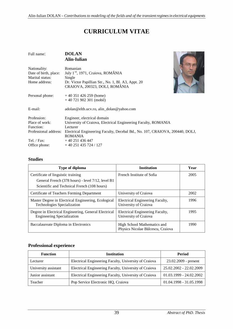
Alin-Iulian DOLAN – Contributions to modeling of the fields and of the transient regimes in electrical equipments
Abstract of PhD. Thesis39
CURRICULUM VITAE
Full name: DOLANAlin-Iulian
Nationality: RomanianDate of birth, place: July 1-st, 1971, Craiova, ROMÂNIAMarital status: SingleHome address: Dr. Victor Papillian Str., No. 1, Bl. A3, Appt. 20
CRAIOVA, 200323, DOLJ, ROMÂNIA
Personal phone: + 40 351 426 259 (home)+ 40 721 902 301 (mobil)
E-mail: [email protected], [email protected]
Profession: Engineer, electrical domainPlace of work: University of Craiova, Electrical Engineering Faculty, ROMANIAFunction: LecturerProfessional address: Electrical Engineering Faculty, Decebal Bd., No. 107, CRAIOVA, 200440, DOLJ,
ROMANIATel. / Fax: + 40 251 436 447Office phone: + 40 251 435 724 / 127
Studies
Type of diploma Institution Year
Certificate of linguistic trainingGeneral French (378 hours) - level 7/12, level B1Scientific and Technical French (108 hours)
French Institute of Sofia 2005
Certificate of Teachers Forming Department University of Craiova 2002
Master Degree in Electrical Engineering, EcologicalTechnologies Specialization
Electrical Engineering Faculty,University of Craiova
1996
Degree in Electrical Engineering, General ElectricalEngineering Specialization
Electrical Engineering Faculty,University of Craiova
1995
Baccalaureate Diploma in Electronics High School Mathematics andPhysics Nicolae B lcescu, Craiova
1990
Professional experience
Function Institution Period
Lecturer Electrical Engineering Faculty, University of Craiova 23.02.2009 - present
University assistant Electrical Engineering Faculty, University of Craiova 25.02.2002 - 22.02.2009
Junior assistant Electrical Engineering Faculty, University of Craiova 01.03.1999 - 24.02.2002
Teacher Pop Service Electronic HQ, Craiova 01.04.1998 - 31.05.1998
Alin-Iulian DOLAN – Contributions to modeling of the fields and of the transient regimes in electrical equipments
Abstract of PhD. Thesis 40
Abroad stages
Stage type Institution Period
International Engineering Doctoral School,Francophone Department, Technical Universityof SofiaScientific coordinator:
Prof. Ivan YATCHEV
31.03.2007 - 01.08.2007PhD. Training - UniversityAgency for Francophonie(AUF)Program no. 6 - Scientificand university mobility
National Polytechnic Institute of Grenoble,Electrical Engineering Laboratory of GrenobleScientific coordinators:
Prof. Gérard MEUNIERProf. Albert FOGGIA
02.10.2006 - 30.03.2007
02.08.2007 - 01.09.2007
26.07.2006 - 31.08.2006
PhD. Training - UniversityAgency for Francophonie(AUF)Program no. 5 - Scientificand institutionalreinforcement of universities
International Doctoral School in Engineering,Francophone Department, Technical Universityof Sofia, Regional Network Engineering forDevelopment (RENED)Scientific coordinator:
Prof. Ivan YATCHEV01.11.2004 - 22.12.2005
01.10.2004 - 22.12.2005Linguistic training -French Embassy inBulgaria, Cooperation andCultural Center
French Institute of Sofia
26.07.2004 - 31.08.2004
Scientific experience• 5 research contracts• 15 scientific papers
Informatics competences• MICROSOFT OFFICE, TURBOPASCAL, FORTRAN, C++, MATHCAD, MATLAB,
QUICKFIELD, FEMM (LUASCRIPT), ANSYS (APDL), ATP-EMTP, FLUX
Teaching fields• Electrical apparatus - applications• Electrical equipments - applications• CAD of Electrical Equipments - applications• High Voltage Engineering - applications• Theoretical Electrical Engineering - applications• Computer programming and programming languages - applications• Statistical Models and Reliability - course• Reliability - course
Foreign languages:• French: read, speak, write• English: read, speak, write
13.11.2009 Signature: