about the user's guide and technical reference manual
TRANSCRIPT
User’s Guide and TechnicalReference Manual
Aironet Wireless LAN AdapterProducts supported:
ISA4500, ISA4800, PCI4800, and PCI4500
DOC-710-003638-A0
ISA PCI
Aironet Wireless Communications, Inc. • 3875 Embassy ParkwayAkron, Ohio 44333-8357
www.aironet.com
Aironet Wireless Communications, Inc.
No part of this document may be reproduced or transmitted in any means, elec-tronic or mechanical, for any purpose, without the written permission of Aironet. Information in this document is subject to change without notice. Aironet makes no representation or warranties with respect to the contents of this manual and specifically disclaims any express or implied warranties of merchantability or fitness for any particular purpose.
© 1999 Aironet Wireless Communications, Inc. All rights reserved.
LM4500TM, LM4800TM, AP4500TM, AP4800TM, PC4500TM, PC4800TM, MC4500TM, MC4800TM, UC4500TM, UC4800TM, ISA4500TM, ISA4800TM, PCI4500TM, PCI4800TM, BR100TM, BR500TM, BRE100TM, BRE500TM, and AironetTM are trademarks of Aironet Wireless Communications, Inc.
Other trademarks used are properties of their respective owners.
Printed in USA
DOC-710-003638-A0
Table of Contents
About the User’s Guide and Technical Reference Manual ......................................................................... vii
Typographical Conventions ................................... ix
Section 1Welcome to the Aironet 4000 Series Wireless LAN Adapter ............................................... 1-1
Safety Information .............................................. 1-2Dipole Antenna ............................................ 1-3High Gain Antennas .................................... 1-3Other Devices in the Wireless Network ....... 1-3
Radio Characteristics ......................................... 1-4Direct Sequence Radio Technology ................... 1-4Data Transparency and Protocols ...................... 1-4Protocols Supported ........................................... 1-5Radio Ranges ..................................................... 1-5
Site Survey .................................................. 1-5Link Test ...................................................... 1-7
Security Features ............................................... 1-7Terminology ........................................................ 1-8System Configurations ..................................... 1-10Coverage Options ............................................ 1-14
Section 2Installing the Hardware .............................................. 2-1
Before You Start ................................................. 2-2Installing the Wireless LAN Adapter ................... 2-4
Installation ................................................... 2-4Configuring the DIP Switches (ISA Only) ........... 2-7
Base Address .............................................. 2-8IRQ Level .................................................... 2-9
Attaching the Antenna ...................................... 2-10Viewing the Indicator Displays ......................... 2-11
i
Section 3Installing the Software ............................................... 3-1
Driver Overview .................................................. 3-1Windows 95 or Windows 98 NDIS3 Installation . 3-4Windows NT NDIS3 Installation ......................... 3-5Windows for Workgroups NDIS2 Installation ..... 3-7DOS NDIS2 Installation ...................................... 3-8DOS Packet Driver Installation ......................... 3-10ODI Driver Installation ...................................... 3-11General Information .......................................... 3-13Driver Keywords and Settings .......................... 3-15
Section 4Utilities ....................................................................... 4-1
Site Survey and Link Test .................................. 4-1Using Windows 3.11 or DOS to Perform a Link Test Using Telnet ................................ 4-2Using Windows 95 or Windows 98 to Perform a Link Test ..................................... 4-4
Link Test Command in WinDGS ........................ 4-5Linkscope .................................................... 4-6
Loading New Firmware Versions ............................... 4-7Upgrading Firmware for Windows 95 orWindows 98......................................................... 4-7Loading Firmware for Windows 3.11 and DOS .. 4-8
Section 5Error Messages and Trouble Shooting ...................... 5-1
Indicator LEDs .................................................... 5-1If Your Radio Fails to Establish Contact ............. 5-3
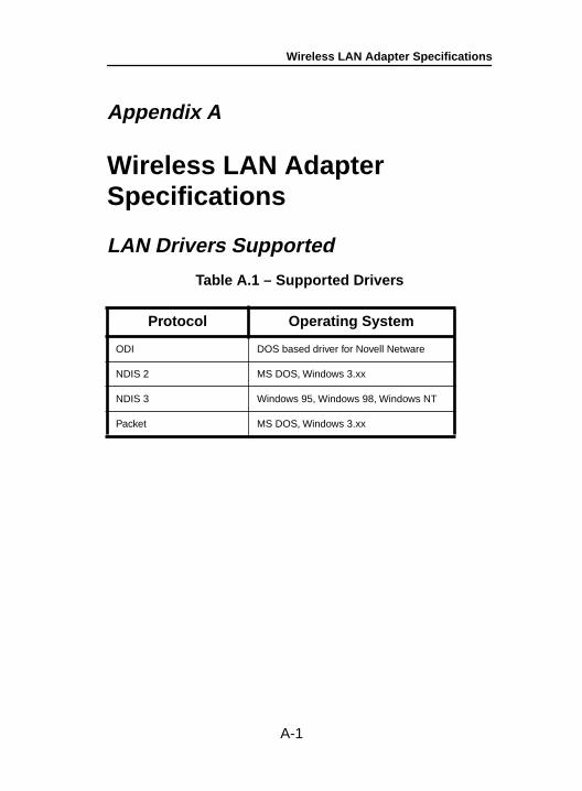
Appendix A Wireless LAN Adapter Specifications .................A-1LAN Drivers Supported ......................................A-1Radio Specifications ...........................................A-2Power Requirements ..........................................A-3Physical Specifications .......................................A-3
ii
Appendix BUsing the WinDGS Utility ...........................................B-1Commands Menu ......................................................B-1
Select Card .........................................................B-1Load New Firmware ...........................................B-2Edit Properties ....................................................B-2Statistics .............................................................B-2Status .................................................................B-2Link Test .............................................................B-3Site Survey .........................................................B-3Radio Off/On ......................................................B-3Exit .....................................................................B-3
Options Menu ............................................................B-4Preferences ........................................................B-4Screen Update Timer .........................................B-4Save Properties Options ....................................B-5
Edit Parameters .........................................................B-5System Parameters ............................................B-6
Name ...........................................................B-6SSID ............................................................B-6Network type (Infrastructure Mode) .............B-6Network type (Ad Hoc Mode) ......................B-7Constant Awake Mode (CAM) .....................B-7Power Save Mode .......................................B-7Fast Power Save Mode ...............................B-7
Network Parameters ...........................................B-8RF Network Parameters .....................................B-8Advanced (Infrastructure) .................................B-10
Specified Access Point ..............................B-10RTS Threshold ..........................................B-10RTS Retry Limit .........................................B-11
Advanced (Ad Hoc/IBSS) .................................B-11Channel .....................................................B-11Beacon Period ...........................................B-12Wake Duration ..........................................B-12
iii
Appendix CManufacturers Federal CommunicationCommission Declaration of ConformityStatement.......................................................... C-1Department of Communications–CanadaCanadian Compliance Statement ..................... C-2European Telecommunications StandardsInstitute Statement of ComplianceInformation to User............................................ C-3Declaration of Conformity.................................. C-4
Appendix DTechnical Support ...............................................D-1
Communications .........................................D-1Web Site ......................................................D-1
iv
v
List of Figures
Figure 1.1 -
Ad Hoc Wireless LAN ............................... 1-10
Figure 1.2 -
Wireless Infrastructure .............................. 1-11
Figure 1.3 -
Wireless Infrastructure with WorkstationsAccessing a Wired LAN ............................ 1-12
Figure 1.4 -
Extended Infrastructure Using Repeaters. 1-13
Figure 1.5 -
Minimal Overlap Coverage Option............ 1-14
Figure 1.6 -
Heavy Overlap Coverage Option .............. 1-15
Figure 1.7 -
Multiple Overlapping Systems CoverageOption ....................................................... 1-16
Figure 2.1 -
Overview of the Wireless LAN Adapter....... 2-3
vi
List of Tables
Table 3.1 -
Driver Disk Structure................................... 3-2
Table 3.2 -
Minimum PROTOCOL.INI Driver Settings .. 3-8
Table 3.3 -
Minimum AWCPKT.INI Driver Settings..... 3-10
Table 3.4 -
Minimum NET.CFG Driver Settings .......... 3-12
Table 3.5 -
General Network Keywords ...................... 3-16
Table 3.6 -
Advanced Network Keywords ................... 3-18
Table 3.7 -
Fragmentation Keywords .......................... 3-19
Table 3.8 -
Power Management Keywords ................. 3-20
Table 3.9 -
Scanning Keywords .................................. 3-22
Table 3.10 -
Infrastructure Keywords ............................ 3-23
Table 3.11 -
Ad Hoc Keywords ..................................... 3-24
Table 3.12 -
Wireless LAN Adapter Keywords.............. 3-25
Table 5.1 -
Green LED Operating Messages................ 5-2
Table 5.2 -
Amber LED Operating Messages ............... 5-2
Table A.1 -
Supported Drivers .......................................A-1
Table A.2 -
Radio Specifications ...................................A-2
Table A.3 -
Power Requirements ..................................A-3
Table A.4 -
Physical Charactistics .................................A-3
About the User’s Guide and Technical Reference Manual
About the User’s Guide and Technical Reference ManualThis guide covers the installation, configuration, control, and maintenance of your Aironet 4000 Series Wireless LAN Adapter.
Please read Sections 2 and 3 before attempting to install or use the hardware and software described in this guide.
This Guide is arranged as follows:
Section 1 – Welcome to the Aironet 4000 Series Wireless LAN Adapter – provides you with a general introduction to the 4000 Series Card, direct sequence radio technology, and the various configurations you can use when operating the 4000 Series Card in your infrastructure.
Section 2 – Installing the Hardware – describes the physi-cal installation of the Wireless LAN Adapter and antenna.
Section 3 – Installing the Software – describes installation and configuration of the various network drivers.
Section 4 – Utilities – provides detailed procedures for using the utilities to perform link tests and site surveys as well as loading new firmware versions.
Section 5 – Error Messages and Troubleshooting – provides detailed descriptions of the LED messages and error codes, as well as general procedures for correcting common problems.
vii
About the User’s Guide and Technical Reference Manual
Appendix A – Wireless LAN Adapter Specifications – provides radio and physical specifications.
Appendix B – Using the WinDGS Utility – provides detailed descriptions on using the WinDGS utility.
Appendix C – Channels – provides channel identifiers and channel center frequencies for various area regulatory agencies.
Appendix D – Declaration of Conformity – provides conformity information about the Wireless LAN Adapter.
Appendix E – Technical Support – provides contact information for Aironet.
viii

About the User’s Guide and Technical Reference Manual
Typographical Conventions
When reading the User’s Guide and Technical Reference Manual, it is important to understand the symbol and formatting conventions used in the documentation. The fol-lowing symbols are used in the guide.
Convention Type of Information
Indicates a note which contains important information.
A caution message that appears before procedures which, if not observed, could result in loss of data or damage to the equipment.
Bold type An action you must perform such as type or select.
ix

About the User’s Guide and Technical Reference Manual
x
Welcome to the Aironet 4000 Series Wireless LAN Adapter
Section 1
Welcome to the Aironet 4000 Series Wireless LAN AdapterThe Aironet 4000 Series Wireless LAN Adapter provides transparent wireless data communications between fixed, portable, or mobile devices and other wireless devices or a wired network infrastructure (Ethernet or Token Ring). Host devices can be any device equipped with a PC/AT, PC/XT, ISA (Industry Standard Architecture), or 32 bit PCI (Periph-eral Component Interconnect) slot.
The Wireless LAN Adapter is fully compatible when used in a device supporting Plug-and-Play technology.
1-1
Welcome to the Aironet 4000 Series Wireless LAN Adapter
Safety Information
The FCC with its action in ET Docket 96-8 has adopted a safety standard for human exposure to radio frequency (RF) electromagnetic energy emitted by FCC certified equip-ment. The Aironet products meet the uncontrolled environ-mental limits found in OET-65 and ANSI C95.1, 1991. Proper operation of this radio according to the instructions found in this manual will result in the user exposure to be substantially below the FCC recommended limits.
• Do not touch or move antenna(s) while the unit is transmitting or receiving.
• Do not hold any component containing the radio such that the antenna is very close or touching any exposed parts of the body, especially the face or eyes, while transmitting.
• Do not operate a portable transmitter near unshielded blasting caps or in an explosive environment unless it is a type especially qualified for such use.
• Do not operate radio or attempt to transmit data unless the antenna is connected, if not, the radio may be damaged.
LISTED
UL®
®
1-2
Welcome to the Aironet 4000 Series Wireless LAN Adapter
Dipole Antenna
Always orient antenna such that it is at least 15 cm (6 inches) away from your body.
High Gain Antennas
High gain wall mount or mast mount antennas are designed to be professionally installed and should be located at a minimum distance of 30 cm (12 inches) or more from your body. Please contact your professional installer, VAR, or antenna manufacturer for proper installation requirements.
Other Devices in the Wireless Network
Refer to the User’s Guide or Technical Reference Manual for the Access Point, Universal Client, or Bridge for additional information.
1-3
Welcome to the Aironet 4000 Series Wireless LAN Adapter
Radio Characteristics
The Wireless LAN Adapter operates in the 2.4 GHz license-free Industrial Scientific and Medical (ISM) band. Data is transmitted over a half-duplex radio channel operating up to 2 Mbps (4500 Series) or 11 Mbps (4800 Series).
Direct Sequence Radio Technology
The Aironet 4000 Series Wireless LAN Adapter uses Direct Sequence Spread Spectrum (DSSS) transmission previously developed for military “anti-jamming” and “low probability of intercept” radio systems. The signal is transmitted over a wide frequency range, using multiplefrequencies. This protects the data transmission from inter-ference.
Data Transparency and Protocols
The Aironet 4000 Series Wireless LAN Adapter transports data packets transparently as they move through the wireless infrastructure. The Wireless LAN Adapter operates similarly to a standard network product except the wire is replaced with a radio connection. No special wireless net-working functions are required. All existing applications, which operate over a network, will operate using the Aironet 4000 Series Wireless LAN Adapter.
1-4
Welcome to the Aironet 4000 Series Wireless LAN Adapter
Protocols Supported
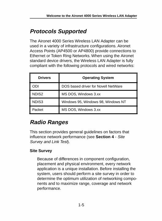
The Aironet 4000 Series Wireless LAN Adapter can be used in a variety of infrastructure configurations. Aironet Access Points (AP4500 or AP4800) provide connections to Ethernet or Token Ring Networks. When using the Aironet standard device drivers, the Wireless LAN Adapter is fully compliant with the following protocols and wired networks:
Radio Ranges
This section provides general guidelines on factors that influence network performance (see Section 4 - Site Survey and Link Test).
Site Survey
Because of differences in component configuration, placement and physical environment, every network application is a unique installation. Before installing the system, users should perform a site survey in order to determine the optimum utilization of networking compo-nents and to maximize range, coverage and network performance.
Drivers Operating System
ODI DOS based driver for Novell NetWare
NDIS2 MS DOS, Windows 3.xx
NDIS3 Windows 95, Windows 98, Windows NT
Packet MS DOS, Windows 3.xx
1-5
Welcome to the Aironet 4000 Series Wireless LAN Adapter
Here are some operating and environmental conditions that need to be considered:
• Data Rates. Sensitivity and range are inversely propor-tional to data bit rates. The maximum radio range is achieved at the lowest workable data rate. There will be a decrease in receiver threshold sensitivity as the radio data rate increases.
• Antenna Type and Placement . Proper antenna config-uration is a critical factor in maximizing radio range. As a general guide, range increases in proportion to antenna height.
For a detailed explanation of antenna types and config-urations along with guidelines on selecting antennas for specific environments, see the Aironet Antenna Guide, document number 710-003725.
• Physical Environments. Clear or open areas provide better radio range than closed or filled areas. Also, the less cluttered the work environment, the greater the range.
• Obstructions. A physical obstruction such as metal shelving or a steel pillar can hinder the performance of the Wireless LAN Adapter. Avoid locating the comput-ing device and antenna in a location where there is a metal barrier between the sending and receiving antennas.
• Building Materials. Radio penetration is greatly influ-enced by the building material used in construction. For example, drywall construction allows greater range than concrete blocks. Metal or steel construction is a barrier to radio signals.
1-6
Welcome to the Aironet 4000 Series Wireless LAN Adapter
Link Test
The link test tool is used to determine RF coverage. The test results help the installer eliminate low RF signal level area that can result in loss of connection.
Security Features
The Aironet 4000 Series Wireless LAN Adapter employs Direct Sequence Spread Spectrum Technology, previously developed for military “anti-jamming” and “low probability of intercept” radio systems.
The Aironet Access Point must be set to the same Service Set Identifier (SSID) as all other Aironet devices on the wireless infrastructure. Units with a different SSID will not be able to directly communicate with each other.
1-7
Welcome to the Aironet 4000 Series Wireless LAN Adapter
Terminology
When configuring your system, and when reading this manual, keep in mind the following terminology:
Association – Each root unit or repeater in the infrastructure contains an association table that controls the routing of packets between the Access Point and the wireless infrastructure. The association table maintains entries for all the nodes situated below the Access Point on the infrastructure including repeaters and client nodes.
End Node – A client node that is located at the end of the Network Tree.
Infrastructure – The wireless infrastructure is the communications system that combines Access Points, mobile nodes and fixed nodes. Access Points within the infrastructure can be either root units, which are physically wired to the LAN backbone, or can act as wireless repeat-ers. Other RF enabled devices serve as fixed nodes or mobile client nodes.
Parent/Child Node – Refers to the relationships between nodes in the wireless infrastructure. The complete set of relationships is sometimes described as a Network Tree. For example, the Access Point (at the top of the tree) would be the parent of the end nodes. Conversely, the end nodes would be the children of the Access Point.
1-8
Welcome to the Aironet 4000 Series Wireless LAN Adapter
Power Saving Protocol (PSP) and Non-Power Saving Protocol – The Power Saving Protocol allows computers (usually portable computers) to power up only part of the time to conserve energy. If a client node is using the Power Saving Protocol to communicate with the network, the Aironet Access Point must be aware of this mode and implement additional features such as message store and forward. If the client node is powered from an AC line, PSP should not be used.
Repeater – A repeater is an Access Point that extends the radio range of the infrastructure. A repeater is not physically attached to the wired LAN, but communicates via radio to another Access Point, which is either a root unit or another repeater.
Root Unit – The root unit is an Access Point that is located at the top, or starting point, of a wireless infrastructure. A root unit provides the physical connection to the wired LAN (such as Ethernet or Token Ring) and contains configuration information in its association table that covers all nodes that access the wired network (backbone). All Access Points directly attached to the wired LAN backbone are root units.
1-9
Welcome to the Aironet 4000 Series Wireless LAN Adapter
System Configurations
The Aironet 4000 Series Wireless LAN Adapter can be used in a variety of network system configurations. Aironet Access Points (AP4500 or AP4800) provide connections to your Ethernet or Token Ring networks or act as repeaters increasing wireless communication range. The maximum communication range is based on how you configure your wireless infrastructure.
Examples of some common system configurations are shown on the pages that follow, along with a description of each.
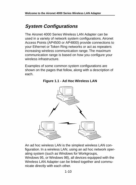
Figure 1.1 - Ad Hoc Wireless LAN
An ad hoc wireless LAN is the simplest wireless LAN con-figuration. In a wireless LAN, using an ad hoc network oper-ating system (such as Windows for Workgroups, Windows 95, or Windows 98), all devices equipped with the Wireless LAN Adapter can be linked together and commu-nicate directly with each other.
1-10
Welcome to the Aironet 4000 Series Wireless LAN Adapter
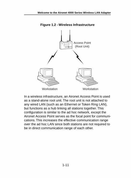
Figure 1.2 - Wireless Infrastructure
In a wireless infrastructure, an Aironet Access Point is used as a stand-alone root unit. The root unit is not attached to any wired LAN (such as an Ethernet or Token Ring LAN), but functions as a hub linking all stations together. This configuration is similar to the ad hoc network, except the Aironet Access Point serves as the focal point for communi-cations. This increases the effective communication range over the ad hoc LAN since both stations are not required to be in direct communication range of each other.
Workstation
Access Point(Root Unit)
Workstation
1-11
Welcome to the Aironet 4000 Series Wireless LAN Adapter
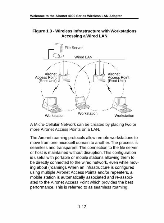
Figure 1.3 - Wireless Infrastructure with Workstations Accessing a Wired LAN
A Micro-Cellular Network can be created by placing two or more Aironet Access Points on a LAN.
The Aironet roaming protocols allow remote workstations to move from one microcell domain to another. The process is seamless and transparent. The connection to the file server or host is maintained without disruption. This configuration is useful with portable or mobile stations allowing them to be directly connected to the wired network, even while mov-ing about (roaming). When an infrastructure is configured using multiple Aironet Access Points and/or repeaters, a mobile station is automatically associated and re-associ-ated to the Aironet Access Point which provides the best performance. This is referred to as seamless roaming.
File Server
Wired LAN
WorkstationWorkstation
Workstation
AironetAccess Point
(Root Unit)
AironetAccess Point(Root Unit)
1-12
Welcome to the Aironet 4000 Series Wireless LAN Adapter
1-13
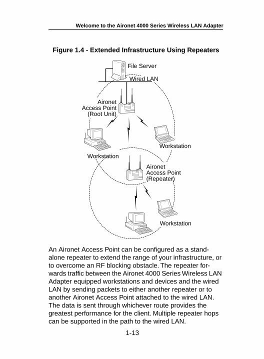
Figure 1.4 - Extended Infrastructure Using Repeaters
An Aironet Access Point can be configured as a stand-alone repeater to extend the range of your infrastructure, or to overcome an RF blocking obstacle. The repeater for-wards traffic between the Aironet 4000 Series Wireless LAN Adapter equipped workstations and devices and the wired LAN by sending packets to either another repeater or to another Aironet Access Point attached to the wired LAN. The data is sent through whichever route provides the greatest performance for the client. Multiple repeater hops can be supported in the path to the wired LAN.
File Server
Wired LAN
Workstation
AironetAccess Point
(Root Unit)
AironetAccess Point(Repeater)
Workstation
Workstation
Welcome to the Aironet 4000 Series Wireless LAN Adapter
Coverage Options
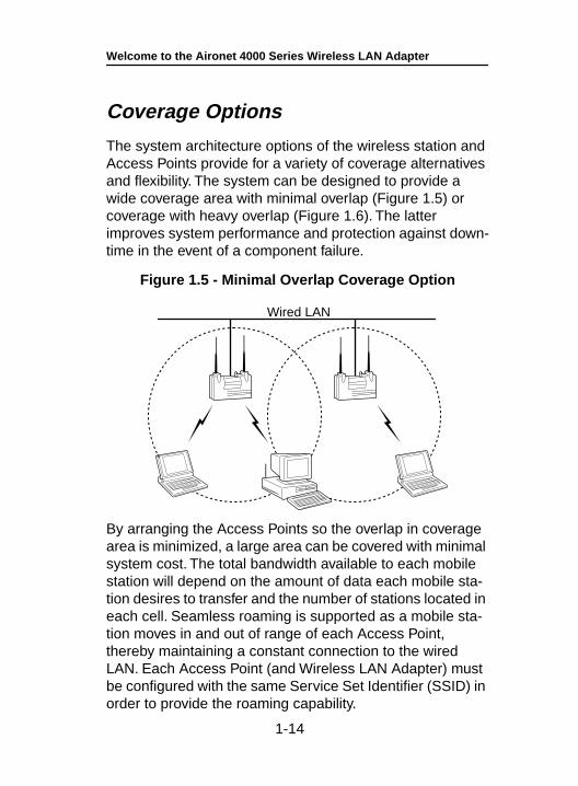
The system architecture options of the wireless station and Access Points provide for a variety of coverage alternatives and flexibility. The system can be designed to provide a wide coverage area with minimal overlap (Figure 1.5) or coverage with heavy overlap (Figure 1.6). The latter improves system performance and protection against down-time in the event of a component failure.
Figure 1.5 - Minimal Overlap Coverage Option
By arranging the Access Points so the overlap in coverage area is minimized, a large area can be covered with minimal system cost. The total bandwidth available to each mobile station will depend on the amount of data each mobile sta-tion desires to transfer and the number of stations located in each cell. Seamless roaming is supported as a mobile sta-tion moves in and out of range of each Access Point, thereby maintaining a constant connection to the wired LAN. Each Access Point (and Wireless LAN Adapter) must be configured with the same Service Set Identifier (SSID) in order to provide the roaming capability.
Wired LAN
1-14
Welcome to the Aironet 4000 Series Wireless LAN Adapter
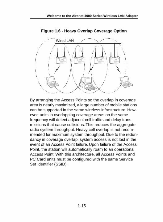
Figure 1.6 - Heavy Overlap Coverage Option
By arranging the Access Points so the overlap in coverage area is nearly maximized, a large number of mobile stations can be supported in the same wireless infrastructure. How-ever, units in overlapping coverage areas on the same frequency will detect adjacent cell traffic and delay trans-missions that cause collisions. This reduces the aggregate radio system throughput. Heavy cell overlap is not recom-mended for maximum system throughput. Due to the redun-dancy in coverage overlap, system access is not lost in the event of an Access Point failure. Upon failure of the Access Point, the station will automatically roam to an operational Access Point. With this architecture, all Access Points and PC Card units must be configured with the same Service Set Identifier (SSID).
Wired LAN
1-15
Welcome to the Aironet 4000 Series Wireless LAN Adapter
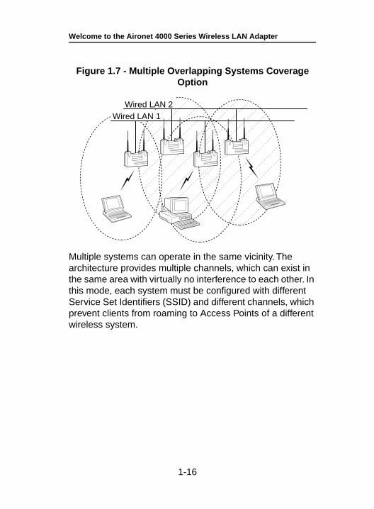
Figure 1.7 - Multiple Overlapping Systems Coverage Option
Multiple systems can operate in the same vicinity. The architecture provides multiple channels, which can exist in the same area with virtually no interference to each other. In this mode, each system must be configured with different Service Set Identifiers (SSID) and different channels, which prevent clients from roaming to Access Points of a different wireless system.
Wired LAN 1Wired LAN 2
1-16
Installing the Hardware
Section 2
Installing the HardwareThis section describes the procedures for installing the Wireless LAN Adapter.
Here’s what you’ll find in this section:
• Before You Start
• Installing the Wireless LAN Adapter
• Configuring the DIP Switches (ISA Only)
• Attaching the Antenna
• Viewing the Indicator Displays
2-1
Installing the Hardware
Before You Start
For the Wireless LAN Adapter to be used with a computing device, the device must be equipped with a PC/AT, ISA, or PCI slot. Please follow the manufacturers guidelines for installing the software as well as installing the Wireless LAN Adapter.
After unpacking the Wireless LAN Adapter, make sure the following items are present and in good condition:
• Wireless LAN Adapter (ISA or PCI)
• Standard 2 dBi dipole antenna
• Software Driver Diskette
If any item is damaged or missing, contact your Aironet supplier. Save all shipping and packing material in order to repack the unit should service be required.
NOTE: Any remote antenna and its associated wiring are ordered and packed separately.
2-2
Installing the Hardware
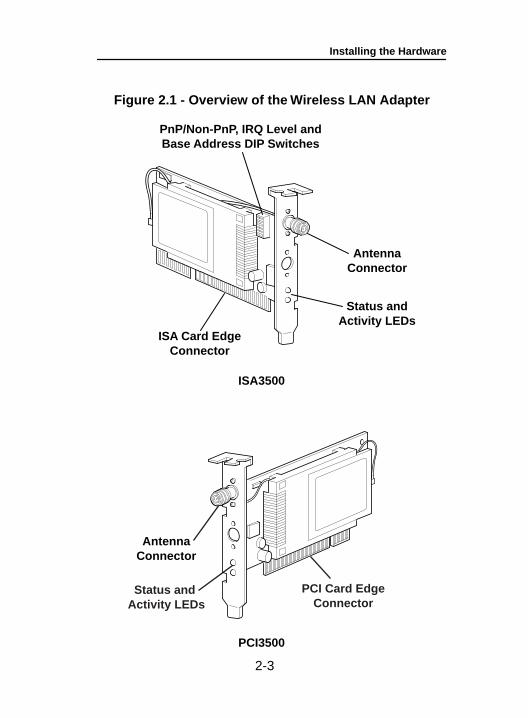
Figure 2.1 - Overview of the Wireless LAN Adapter
PnP/Non-PnP, IRQ Level andBase Address DIP Switches
Status andActivity LEDs
AntennaConnector
AntennaConnector
ISA Card EdgeConnector
ISA3500
PCI3500
PCI Card EdgeConnector
Status and Activity LEDs
2-3
Installing the Hardware
Installing the Wireless LAN Adapter
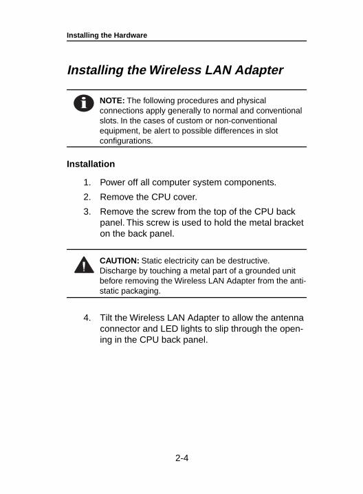
NOTE: The following procedures and physical connections apply generally to normal and conventional slots. In the cases of custom or non-conventional equipment, be alert to possible differences in slot configurations.
Installation
1. Power off all computer system components.
2. Remove the CPU cover.
3. Remove the screw from the top of the CPU back panel. This screw is used to hold the metal bracket on the back panel.
CAUTION: Static electricity can be destructive. Discharge by touching a metal part of a grounded unit before removing the Wireless LAN Adapter from the anti-static packaging.
4. Tilt the Wireless LAN Adapter to allow the antenna connector and LED lights to slip through the open-ing in the CPU back panel.
2-4
Installing the Hardware
2-5
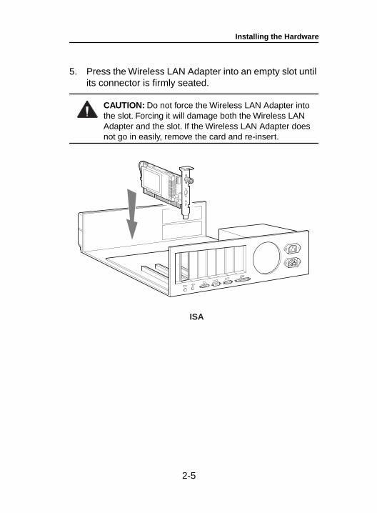
5. Press the Wireless LAN Adapter into an empty slot until its connector is firmly seated.
CAUTION: Do not force the Wireless LAN Adapter into the slot. Forcing it will damage both the Wireless LAN Adapter and the slot. If the Wireless LAN Adapter does not go in easily, remove the card and re-insert.
ISA
Installing the Hardware
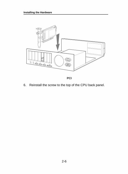
6. Reinstall the screw to the top of the CPU back panel.
PCI
2-6
Installing the Hardware
2-7
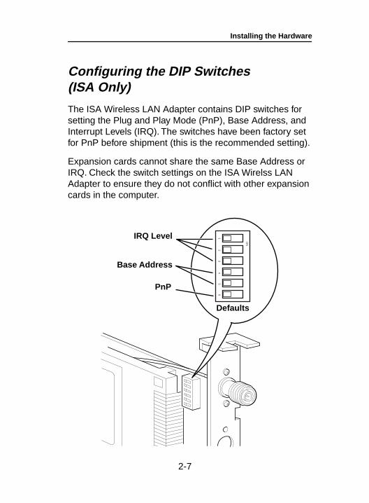
Configuring the DIP Switches (ISA Only)
The ISA Wireless LAN Adapter contains DIP switches for setting the Plug and Play Mode (PnP), Base Address, and Interrupt Levels (IRQ). The switches have been factory set for PnP before shipment (this is the recommended setting).
Expansion cards cannot share the same Base Address or IRQ. Check the switch settings on the ISA Wirelss LAN Adapter to ensure they do not conflict with other expansion cards in the computer.
IRQ Level
Base Address
PnP
Defaults
ON
12
34
56
Installing the Hardware
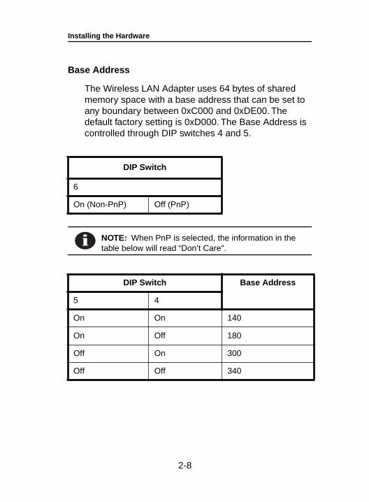
Base Address
The Wireless LAN Adapter uses 64 bytes of shared memory space with a base address that can be set to any boundary between 0xC000 and 0xDE00. The default factory setting is 0xD000. The Base Address is controlled through DIP switches 4 and 5.
NOTE: When PnP is selected, the information in the table below will read “Don’t Care”.
DIP Switch
6
On (Non-PnP) Off (PnP)
DIP Switch Base Address
5 4
On On 140
On Off 180
Off On 300
Off Off 340
2-8
Installing the Hardware
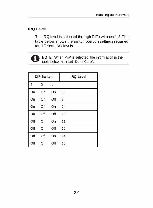
IRQ Level
The IRQ level is selected through DIP switches 1-3. The table below shows the switch position settings required for different IRQ levels.
NOTE: When PnP is selected, the information in the table below will read “Don’t Care”.
DIP Switch IRQ Level
3 2 1
On On On 5
On On Off 7
On Off On 9
On Off Off 10
Off On On 11
Off On Off 12
Off Off On 14
Off Off Off 15
2-9
Installing the Hardware
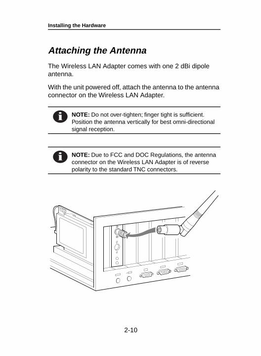
Attaching the Antenna
The Wireless LAN Adapter comes with one 2 dBi dipole antenna.
With the unit powered off, attach the antenna to the antenna connector on the Wireless LAN Adapter.
NOTE: Do not over-tighten; finger tight is sufficient. Position the antenna vertically for best omni-directional signal reception.
NOTE: Due to FCC and DOC Regulations, the antenna connector on the Wireless LAN Adapter is of reverse polarity to the standard TNC connectors.
2-10
Installing the Hardware
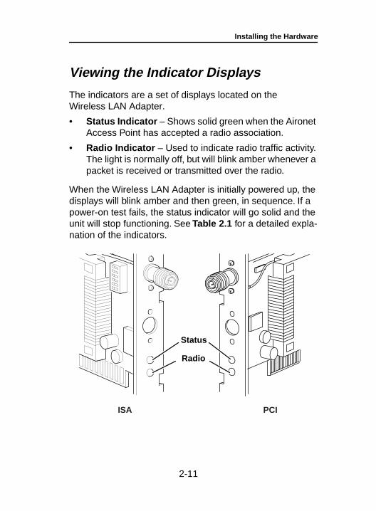
Viewing the Indicator Displays
The indicators are a set of displays located on the Wireless LAN Adapter.
• Status Indicator – Shows solid green when the Aironet Access Point has accepted a radio association.
• Radio Indicator – Used to indicate radio traffic activity. The light is normally off, but will blink amber whenever a packet is received or transmitted over the radio.
When the Wireless LAN Adapter is initially powered up, the displays will blink amber and then green, in sequence. If a power-on test fails, the status indicator will go solid and the unit will stop functioning. See Table 2.1 for a detailed expla-nation of the indicators.
Status
Radio
ISA PCI
2-11
Installing the Hardware
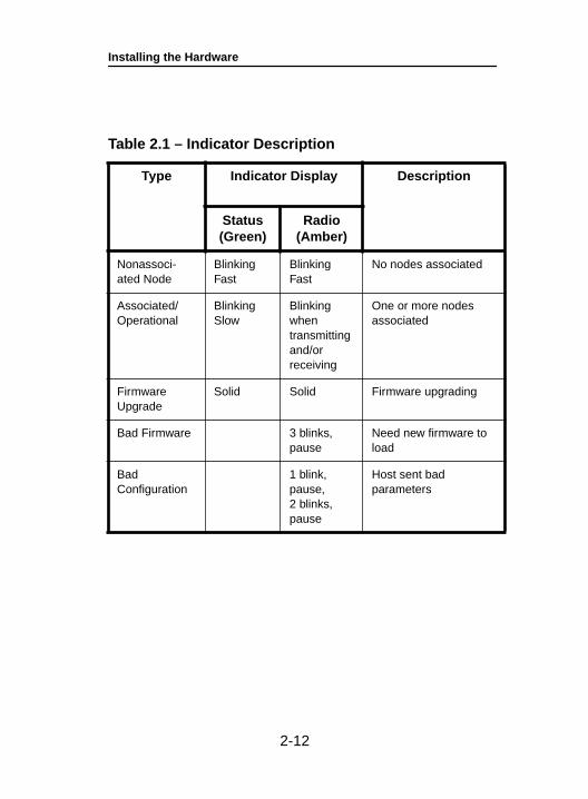
Table 2.1 – Indicator Description
Type Indicator Display Description
Status(Green)
Radio(Amber)
Nonassoci-ated Node
Blinking Fast
Blinking Fast
No nodes associated
Associated/Operational
Blinking Slow
Blinking when transmitting and/or receiving
One or more nodes associated
Firmware Upgrade
Solid Solid Firmware upgrading
Bad Firmware 3 blinks, pause
Need new firmware to load
Bad Configuration
1 blink, pause, 2 blinks, pause
Host sent bad parameters
2-12

Installing the Software
Section 3
Installing the SoftwareThe Wireless LAN Adapter is supplied with PACKET, NDIS2, NDIS3 and ODI drivers allowing operation under DOS, Windows 3.x, Windows for Workgroups, Windows 95, Windows 98, Windows NT, and Novell Netware. The Wireless LAN Adapter is fully IEEE 802.11 compliant.
Driver Overview
The Wireless LAN Adapter is shipped with two diskettes:
• WinDGS diagnostics diskette
• Aironet driver diskette
This section covers the drivers. The utilities are discussed in Section 4 – Utilities.
The DOS, Windows 3.x and Windows for Workgroups based drivers must have a configuration file created (or edited) with an ASCII text editor. Installation of each driver is discussed in the following tables.
3-1
Installing the Software
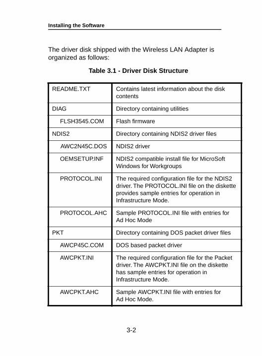
The driver disk shipped with the Wireless LAN Adapter is organized as follows:
Table 3.1 - Driver Disk Structure
README.TXT Contains latest information about the disk contents
DIAG Directory containing utilities
FLSH3545.COM Flash firmware
NDIS2 Directory containing NDIS2 driver files
AWC2N45C.DOS NDIS2 driver
OEMSETUP.INF NDIS2 compatible install file for MicroSoft Windows for Workgroups
PROTOCOL.INI The required configuration file for the NDIS2 driver. The PROTOCOL.INI file on the disketteprovides sample entries for operation in Infrastructure Mode.
PROTOCOL.AHC Sample PROTOCOL.INI file with entries for Ad Hoc Mode
PKT Directory containing DOS packet driver files
AWCP45C.COM DOS based packet driver
AWCPKT.INI The required configuration file for the Packet driver. The AWCPKT.INI file on the diskette has sample entries for operation in Infrastructure Mode.
AWCPKT.AHC Sample AWCPKT.INI file with entries for Ad Hoc Mode.
3-2
Installing the Software
ility
e
ility
e
3-3
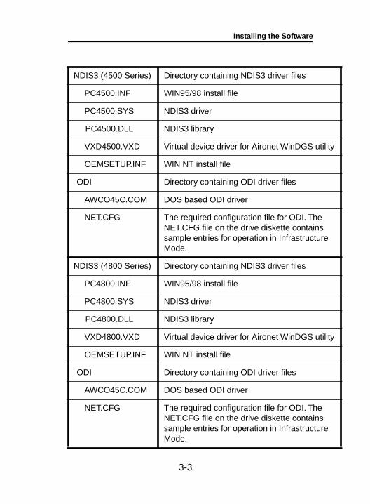
NDIS3 (4500 Series) Directory containing NDIS3 driver files
PC4500.INF WIN95/98 install file
PC4500.SYS NDIS3 driver
PC4500.DLL NDIS3 library
VXD4500.VXD Virtual device driver for Aironet WinDGS ut
OEMSETUP.INF WIN NT install file
ODI Directory containing ODI driver files
AWCO45C.COM DOS based ODI driver
NET.CFG The required configuration file for ODI. TheNET.CFG file on the drive diskette containssample entries for operation in InfrastructurMode.
NDIS3 (4800 Series) Directory containing NDIS3 driver files
PC4800.INF WIN95/98 install file
PC4800.SYS NDIS3 driver
PC4800.DLL NDIS3 library
VXD4800.VXD Virtual device driver for Aironet WinDGS ut
OEMSETUP.INF WIN NT install file
ODI Directory containing ODI driver files
AWCO45C.COM DOS based ODI driver
NET.CFG The required configuration file for ODI. TheNET.CFG file on the drive diskette containssample entries for operation in InfrastructurMode.
Installing the Software
3-4
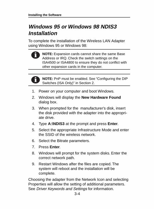
Windows 95 or Windows 98 NDIS3 InstallationTo complete the installation of the Wireless LAN Adapter using Windows 95 or Windows 98:
NOTE: Expansion cards cannot share the same Base Address or IRQ. Check the switch settings on the ISA4500 or ISA4800 to ensure they do not conflict with other expansion cards in the computer.
NOTE: PnP must be enabled. See “Configuring the DIP Switches (ISA Only)” in Section 2.
1. Power on your computer and boot Windows.
2. Windows will display the New Hardware Found dialog box.
3. When prompted for the manufacturer’s disk, insert the disk provided with the adapter into the appropri-ate drive.
4. Type A:\NDIS3 at the prompt and press Enter .
5. Select the appropriate Infrastructure Mode and enter the SSID of the wireless network.
6. Select the Bitrate parameters.
7. Press Enter .
8. Windows will prompt for the system disks. Enter the correct network path.
9. Restart Windows after the files are copied. The system will reboot and the installation will be complete.
Choosing the adapter from the Network Icon and selecting Properties will allow the setting of additional parameters. See Driver Keywords and Settings for information.
Installing the Software
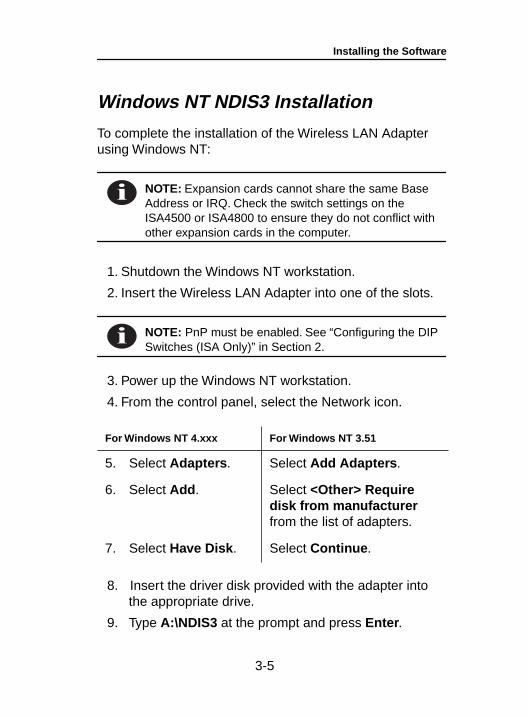
Windows NT NDIS3 Installation
To complete the installation of the Wireless LAN Adapter using Windows NT:
NOTE: Expansion cards cannot share the same Base Address or IRQ. Check the switch settings on the ISA4500 or ISA4800 to ensure they do not conflict with other expansion cards in the computer.
1. Shutdown the Windows NT workstation.
2. Insert the Wireless LAN Adapter into one of the slots.
NOTE: PnP must be enabled. See “Configuring the DIP Switches (ISA Only)” in Section 2.
3. Power up the Windows NT workstation.
4. From the control panel, select the Network icon.
8. Insert the driver disk provided with the adapter into the appropriate drive.
9. Type A:\NDIS3 at the prompt and press Enter .
For Windows NT 4.xxx For Windows NT 3.51
5. Select Adapters . Select Add Adapters .
6. Select Add . Select <Other> Require disk from manufacturer from the list of adapters.
7. Select Have Disk . Select Continue .
3-5
Installing the Software
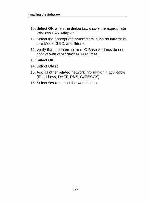
10. Select OK when the dialog box shows the appropriate Wireless LAN Adapter.
11. Select the appropriate parameters, such as Infrastruc-ture Mode, SSID, and Bitrate.
12. Verify that the Interrupt and IO Base Address do not conflict with other devices’ resources.
13. Select OK.
14. Select Close .
15. Add all other related network information if applicable (IP address, DHCP, DNS, GATEWAY).
16. Select Yes to restart the workstation.
3-6
Installing the Software
3-7
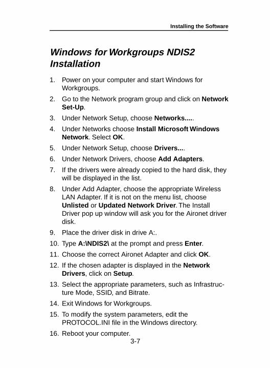
Windows for Workgroups NDIS2 Installation
1. Power on your computer and start Windows for Workgroups.
2. Go to the Network program group and click on NetworkSet-Up.
3. Under Network Setup, choose Networks.... .
4. Under Networks choose Install Microsoft Windows Network . Select OK.
5. Under Network Setup, choose Drivers... .
6. Under Network Drivers, choose Add Adapters .
7. If the drivers were already copied to the hard disk, they will be displayed in the list.
8. Under Add Adapter, choose the appropriate Wireless LAN Adapter. If it is not on the menu list, choose Unlisted or Updated Network Driver . The Install Driver pop up window will ask you for the Aironet driver disk.
9. Place the driver disk in drive A:.
10. Type A:\NDIS2\ at the prompt and press Enter .
11. Choose the correct Aironet Adapter and click OK.
12. If the chosen adapter is displayed in the Network Drivers , click on Setup .
13. Select the appropriate parameters, such as Infrastruc-ture Mode, SSID, and Bitrate.
14. Exit Windows for Workgroups.
15. To modify the system parameters, edit the PROTOCOL.INI file in the Windows directory.
16. Reboot your computer.
Installing the Software
3-8
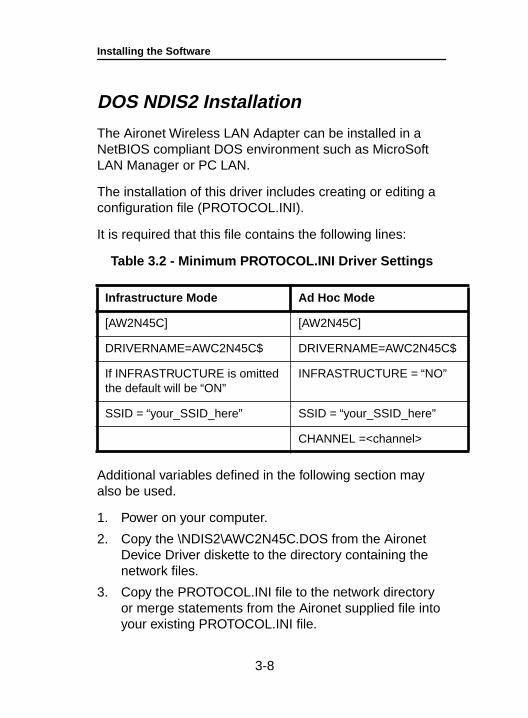
DOS NDIS2 Installation
The Aironet Wireless LAN Adapter can be installed in a NetBIOS compliant DOS environment such as MicroSoft LAN Manager or PC LAN.
The installation of this driver includes creating or editing a configuration file (PROTOCOL.INI).
It is required that this file contains the following lines:
Table 3.2 - Minimum PROTOCOL.INI Driver Settings
Additional variables defined in the following section may also be used.
1. Power on your computer.
2. Copy the \NDIS2\AWC2N45C.DOS from the Aironet Device Driver diskette to the directory containing the network files.
3. Copy the PROTOCOL.INI file to the network directory or merge statements from the Aironet supplied file into your existing PROTOCOL.INI file.
Infrastructure Mode Ad Hoc Mode
[AW2N45C] [AW2N45C]
DRIVERNAME=AWC2N45C$ DRIVERNAME=AWC2N45C$
If INFRASTRUCTURE is omitted the default will be “ON”
INFRASTRUCTURE = “NO”
SSID = “your_SSID_here” SSID = “your_SSID_here”
CHANNEL =<channel>
Installing the Software
4. Modify the CONFIG.SYS file. After the line containing: Device=PROTMAN.DOS, add Device=[drive:] [path] AWC2N45C.DOS.
5. To modify the system parameters, edit the PROTO-COL.INI file in the network directory. For a list of param-eters which can be modified, see Table 3.2 .
6. Reboot your computer.
3-9
Installing the Software
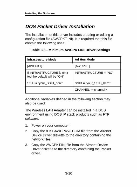
DOS Packet Driver Installation
The installation of this driver includes creating or editing a configuration file (AWCPKT.INI). It is required that this file contain the following lines:
Table 3.3 - Minimum AWCPKT.INI Driver Settings
Additional variables defined in the following section may also be used.
The Wireless LAN Adapter can be installed in a DOS environment using DOS IP stack products such as FTP software.
1. Power on your computer.
2. Copy the \PKT\AWCP45C.COM file from the Aironet Device Driver diskette to the directory containing the network files.
3. Copy the AWCPKT.INI file from the Aironet Device Driver diskette to the directory containing the Packet driver.
Infrastructure Mode Ad Hoc Mode
[AWCPKT] [AWCPKT]
If INFRASTRUCTURE is omit-ted the default will be “ON”
INFRASTRUCTURE = “NO”
SSID = “your_SSID_here” SSID = “your_SSID_here”
CHANNEL =<channel>
3-10
Installing the Software
4. If you would like to modify the system parameters, edit the AWCPKT.INI file. For a list of parameters which can be modified, see Table 3.3 .
5. Load the driver by typing AWCP45C [-cinuw] <int_number> at the DOS prompt (i.e. AWCP45C 0x65) and press Enter .
NOTE: To unload the driver, type AWCP45C –u <int_number> (i.e. AWCP45C –u 0x65).
6. Load the DOS IP stack.
3-11
Installing the Software
ODI Driver Installation
The Wireless LAN Adapter can be installed in an ODI compliant DOS environment such as Novell NetWare.
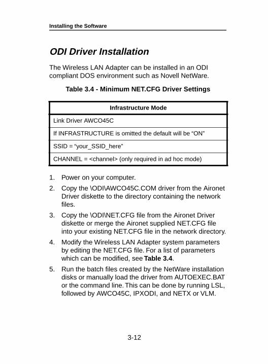
Table 3.4 - Minimum NET.CFG Driver Settings
1. Power on your computer.
2. Copy the \ODI\AWCO45C.COM driver from the Aironet Driver diskette to the directory containing the network files.
3. Copy the \ODI\NET.CFG file from the Aironet Driver diskette or merge the Aironet supplied NET.CFG file into your existing NET.CFG file in the network directory.
4. Modify the Wireless LAN Adapter system parameters by editing the NET.CFG file. For a list of parameters which can be modified, see Table 3.4 .
5. Run the batch files created by the NetWare installation disks or manually load the driver from AUTOEXEC.BAT or the command line. This can be done by running LSL, followed by AWCO45C, IPXODI, and NETX or VLM.
Infrastructure Mode
Link Driver AWCO45C
If INFRASTRUCTURE is omitted the default will be “ON”
SSID = “your_SSID_here”
CHANNEL = <channel> (only required in ad hoc mode)
3-12
Installing the Software
General Information• AWCPKT.INI file must have a section header of
[AWCPKT].
• PROTOCOL.INI file can have any section header, but the section must contain the keyword and parameter DRIVERNAME=“AWC2N45C$”.
• NET.CFG file must have a section header of [Link Driver AWCO45C].
NOTE: These lines may appear anywhere within a section. Only the sections that contain these lines will be parsed.
• Multiple sections are supported.
• Blank lines are supported.
• Comments begin with semi-colon and may appear any-where on a line.
• Keywords can be upper or lower case and may be sur-rounded by white space if desired.
• Any parameter that begins with “0x” will be assumed to be hexadecimal. Any parameter that begins with a digit (excluding the “0x” case) will be assumed to be deci-mal. Any parameter that begins with quotes will be assumed to be a quoted string parameter. Any other parameter will be assumed to be an unquoted string parameter.
• For PROTOCOL.INI string parameters, double quotes are required around the string if the string contains any special characters.
3-13
Installing the Software
NOTE: PROTOCOL.INI does not support some of the white space characters in a quoted string. If a string begins with an alphabetic character and contains no special characters, the quotes may be omitted.
• For Packet string parameters, the string can be enclosed with double quotes or single quotes. If a string is quoted, any character except a “null” and the quote delimiter itself can occur between the quotes.
NOTE: If double quotes are used for a delimiter, a single quote may appear in the string, and vise versa. If the string begins with an alphabetic character and contains no special characters, the quotes may be omitted.
• For numeric parameters, the value can be hexadecimal or decimal. Hexadecimal numbers must be preceded with the characters “0x” but all characters can be upper or lower case.
• Mac address parameters are parsed as string parame-ters, therefore, the addresses must be enclosed in sin-gle or double quotes.
NOTE: The MAC address cannot be a multicast address.
3-14
Installing the Software
Driver Keywords and Settings
The default Wireless LAN Adapter configuration is set to:
• Constant Awake Mode
• Infrastructure Mode – This allows association with any Aironet Access Point matching the SSID supplied by the user
• Receive directed packets to this address as well as multicasts and broadcasts
• Retry data packets up to 16 times before discarding the frame
• Retry RTS sequence up to 16 times before discarding the frame
• RTS exchange on all frames greater than 300 bytes
• Fragment frames longer than 700 bytes
• Kill fragmented transmit packets if not delivered in 5 seconds
• Kill fragmented receive frames if not complete after 10 seconds
• Active scanning with 3 Kµsec energy detect time and 20 Kµsec probe response wait timeout
• Re-scan if eight beacons are consecutively missed
• Send an Access Point keep-alive message every 10 seconds
3-15
Installing the Software
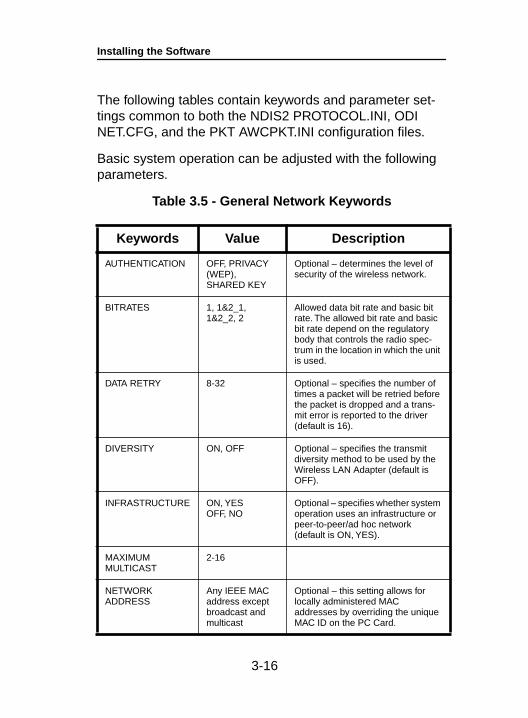
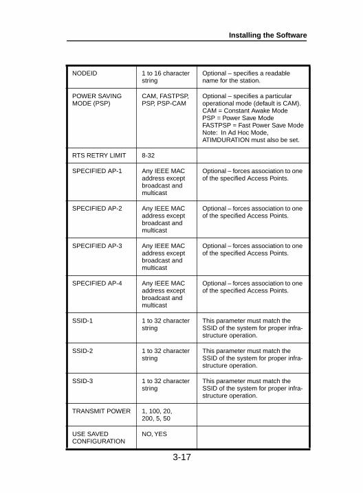
The following tables contain keywords and parameter set-tings common to both the NDIS2 PROTOCOL.INI, ODI NET.CFG, and the PKT AWCPKT.INI configuration files.
Basic system operation can be adjusted with the following parameters.
Table 3.5 - General Network Keywords
Keywords Value Description
AUTHENTICATION OFF, PRIVACY (WEP), SHARED KEY
Optional – determines the level of security of the wireless network.
BITRATES 1, 1&2_1, 1&2_2, 2
Allowed data bit rate and basic bit rate. The allowed bit rate and basic bit rate depend on the regulatory body that controls the radio spec-trum in the location in which the unit is used.
DATA RETRY 8-32 Optional – specifies the number of times a packet will be retried before the packet is dropped and a trans-mit error is reported to the driver (default is 16).
DIVERSITY ON, OFF Optional – specifies the transmit diversity method to be used by the Wireless LAN Adapter (default is OFF).
INFRASTRUCTURE ON, YESOFF, NO
Optional – specifies whether system operation uses an infrastructure or peer-to-peer/ad hoc network (default is ON, YES).
MAXIMUM MULTICAST
2-16
NETWORK ADDRESS
Any IEEE MAC address except broadcast and multicast
Optional – this setting allows for locally administered MAC addresses by overriding the unique MAC ID on the PC Card.
3-16
Installing the Software
NODEID 1 to 16 character string
Optional – specifies a readable name for the station.
POWER SAVING MODE (PSP)
CAM, FASTPSP, PSP, PSP-CAM
Optional – specifies a particular operational mode (default is CAM).CAM = Constant Awake ModePSP = Power Save ModeFASTPSP = Fast Power Save ModeNote: In Ad Hoc Mode, ATIMDURATION must also be set.
RTS RETRY LIMIT 8-32
SPECIFIED AP-1 Any IEEE MAC address except broadcast and multicast
Optional – forces association to one of the specified Access Points.
SPECIFIED AP-2 Any IEEE MAC address except broadcast and multicast
Optional – forces association to one of the specified Access Points.
SPECIFIED AP-3 Any IEEE MAC address except broadcast and multicast
Optional – forces association to one of the specified Access Points.
SPECIFIED AP-4 Any IEEE MAC address except broadcast and multicast
Optional – forces association to one of the specified Access Points.
SSID-1 1 to 32 character string
This parameter must match the SSID of the system for proper infra-structure operation.
SSID-2 1 to 32 character string
This parameter must match the SSID of the system for proper infra-structure operation.
SSID-3 1 to 32 character string
This parameter must match the SSID of the system for proper infra-structure operation.
TRANSMIT POWER 1, 100, 20, 200, 5, 50
USE SAVED CONFIGURATION
NO, YES
3-17
Installing the Software
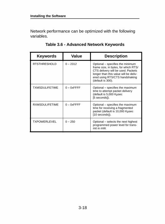
Network performance can be optimized with the following variables.
Table 3.6 - Advanced Network Keywords
Keywords Value Description
RTSTHRESHOLD 0 – 2312 Optional – specifies the minimum frame size, in bytes, for which RTS/CTS delivery will be used. Packets longer than this value will be deliv-ered using RTS/CTS handshaking (default is 300).
TXMSDULIFETIME 0 – 0xFFFF Optional – specifies the maximum time to attempt packet delivery (default is 5,000 Kµsec [5 seconds]).
RXMSDULIFETIME 0 – 0xFFFF Optional – specifies the maximum time for receiving a fragmented packet (default is 10,000 Kµsec [10 seconds]).
TXPOWERLEVEL 0 – 250 Optional – selects the next highest programmed power level for trans-mit in mW.
3-18

Installing the Software
Additional system performance adjustments can be made with the following group of variables.
Table 3.7 - Fragmentation Keywords
Keywords Value Description
FRAGTHRESHOLD 256 – 2312 (must be even)
Optional – specifies the fragmenta-tion size in bytes. Frames longer than this value will be transmitted using multiple packets (default is 700).
3-19
Installing the Software
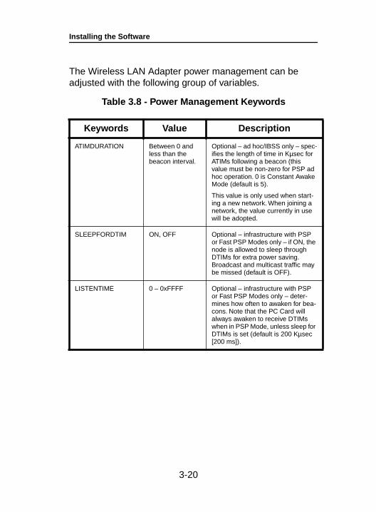
The Wireless LAN Adapter power management can be adjusted with the following group of variables.
Table 3.8 - Power Management Keywords
Keywords Value Description
ATIMDURATION Between 0 and less than the beacon interval.
Optional – ad hoc/IBSS only – spec-ifies the length of time in Kµsec for ATIMs following a beacon (this value must be non-zero for PSP ad hoc operation. 0 is Constant Awake Mode (default is 5).
This value is only used when start-ing a new network. When joining a network, the value currently in use will be adopted.
SLEEPFORDTIM ON, OFF Optional – infrastructure with PSP or Fast PSP Modes only – if ON, the node is allowed to sleep through DTIMs for extra power saving. Broadcast and multicast traffic may be missed (default is OFF).
LISTENTIME 0 – 0xFFFF Optional – infrastructure with PSP or Fast PSP Modes only – deter-mines how often to awaken for bea-cons. Note that the PC Card will always awaken to receive DTIMs when in PSP Mode, unless sleep for DTIMs is set (default is 200 Kµsec [200 ms]).
3-20
Installing the Software
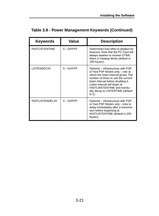
Table 3.8 - Power Management Keywords (Continued)
Keywords Value Description
FASTLISTENTIME 0 – 0xFFFF Determines how often to awaken for beacons. Note that the PC Card will always awaken to receive DTIMs when in Fastpsp Mode (default is 100 Kµsec).
LISTENDECAY 0 – 0xFFFF Optional – infrastructure with PSP or Fast PSP Modes only – rate at which the listen interval grows. The number of times to use the current listen interval before doubling it. Listen interval will begin at FASTLINSTENTIME and eventu-ally decay to LISTENTIME (default is 2).
FASTLISTENDELAY 0 – 0xFFFF Optional – infrastructure with PSP or Fast PSP Modes only – time to delay immediately after a transmis-sion before beginning atFASTLISTENTIME (default is 200 Kµsec).
3-21
Installing the Software
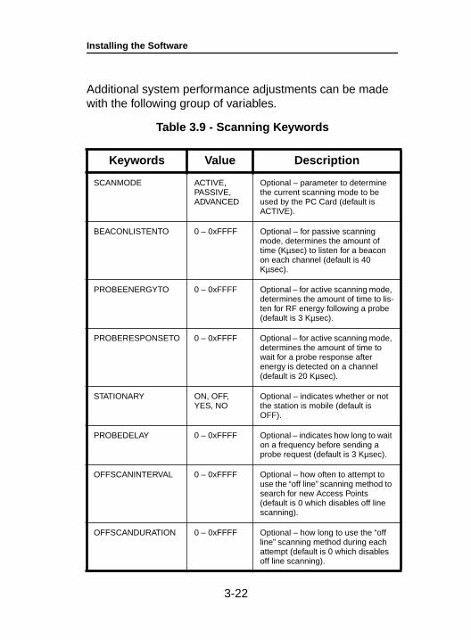
Additional system performance adjustments can be made with the following group of variables.
Table 3.9 - Scanning Keywords
Keywords Value Description
SCANMODE ACTIVE,PASSIVE,ADVANCED
Optional – parameter to determine the current scanning mode to be used by the PC Card (default is ACTIVE).
BEACONLISTENTO 0 – 0xFFFF Optional – for passive scanning mode, determines the amount of time (Kµsec) to listen for a beacon on each channel (default is 40 Kµsec).
PROBEENERGYTO 0 – 0xFFFF Optional – for active scanning mode, determines the amount of time to lis-ten for RF energy following a probe (default is 3 Kµsec).
PROBERESPONSETO 0 – 0xFFFF Optional – for active scanning mode, determines the amount of time to wait for a probe response after energy is detected on a channel (default is 20 Kµsec).
STATIONARY ON, OFF,YES, NO
Optional – indicates whether or not the station is mobile (default is OFF).
PROBEDELAY 0 – 0xFFFF Optional – indicates how long to wait on a frequency before sending a probe request (default is 3 Kµsec).
OFFSCANINTERVAL 0 – 0xFFFF Optional – how often to attempt to use the “off line” scanning method to search for new Access Points (default is 0 which disables off line scanning).
OFFSCANDURATION 0 – 0xFFFF Optional – how long to use the “off line” scanning method during each attempt (default is 0 which disables off line scanning).
3-22
Installing the Software
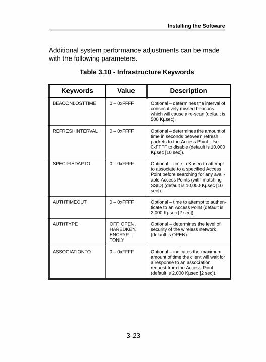
Additional system performance adjustments can be made with the following parameters.
Table 3.10 - Infrastructure Keywords
Keywords Value Description
BEACONLOSTTIME 0 – 0xFFFF Optional – determines the interval of consecutively missed beacons which will cause a re-scan (default is 500 Kµsec).
REFRESHINTERVAL 0 – 0xFFFF Optional – determines the amount of time in seconds between refresh packets to the Access Point. Use 0xFFFF to disable (default is 10,000 Kµsec [10 sec]).
SPECIFIEDAPTO 0 – 0xFFFF Optional – time in Kµsec to attempt to associate to a specified Access Point before searching for any avail-able Access Points (with matching SSID) (default is 10,000 Kµsec [10 sec]).
AUTHTIMEOUT 0 – 0xFFFF Optional – time to attempt to authen-ticate to an Access Point (default is 2,000 Kµsec [2 sec]).
AUTHTYPE OFF, OPEN,HAREDKEY,ENCRYP-TONLY
Optional – determines the level of security of the wireless network (default is OPEN).
ASSOCIATIONTO 0 – 0xFFFF Optional – indicates the maximum amount of time the client will wait for a response to an association request from the Access Point (default is 2,000 Kµsec [2 sec]).
3-23
Installing the Software
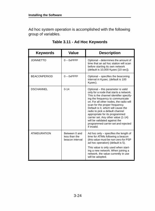
Ad hoc system operation is accomplished with the following group of variables.
Table 3.11 - Ad Hoc Keywords
Keywords Value Description
JOINNETTO 0 – 0xFFFF Optional – determines the amount of time that an ad hoc station will scan before starting its own network (default is 10,000 Kµsec [10 sec]).
BEACONPERIOD 0 – 0xFFFF Optional – specifies the beaconing interval in Kµsec. (default is 100 Kµsec).
DSCHANNEL 0-14 Optional – this parameter is valid only for a node that starts a network. This is the channel identifier specify-ing the frequency to communicate on. For all other nodes, the radio will scan for the proper frequency. Default is 0, which will cause the radio to pick a default channel appropriate for its programmed carrier set. Any other value (1-14) will be validated against the programmed carrier set and rejected if invalid.
ATIMDURATION Between 0 and less than the beacon interval
Ad hoc only – specifies the length of time for ATIMs following a beacon (this value must be non-zero for PSP ad hoc operation) (default is 5).
This value is only used when start-ing a new network. When joining a network, the value currently in use will be adopted.
3-24
Installing the Software
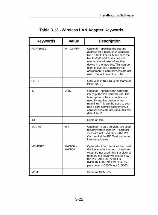
Table 3.12 - Wireless LAN Adapter Keywords
Keywords Value Description
PORTBASE 0 – 0xFFFF Optional – specifies the starting address for a block of 64 consecu-tive 16-bit I/O ports. Make sure the block of I/O addresses does not overlap the address of another device in the machine. This can be used to override a card service assignment. If card services are not used, this will default to 0x140.
PORT Only valid in NET.CFG file (same as PORTBASE).
INT 2-15 Optional – specifies the hardware interrupt the PC Card will use. The Interrupt must be unique (i.e. not used by another device in the machine). This can be used to over-ride a card service assignment. If card services are not used, this will default to 11.
IRQ Same as INT.
SOCKET 0-7 Optional – If card services are used, this keyword is ignored. If card ser-vices are not used, this is the PC Card socket the PC Card is inserted into (default is 0).
MEMORY 0xC000 – 0xDF00
Optional – If card services are used, this keyword is ignored. If card ser-vices are not used, this is a block of memory the driver will use to view the PC Card CIS (default is 0xD000). In the NET.CFG file the parameter is D0000, not 0xD000.
MEM Same as MEMORY.
3-25

Installing the Software
3-26
Utilities
4-1
Section 4
UtilitiesThis section describes procedures for using utilities and updating firmware depending on the operating system used.
See Appendix B for detailed configuration procedures for WinDGS using Windows 95 or Windows 98.
Here’s what you will find in this section:
• Using the utilities
• Loading new firmware versions
Site Survey and Link TestIn order to perform a meaningful site survey, it is necessary to conduct a test that will accurately model the intended use of the system. It is important to perform a site survey using equipment which is similar to that implemented. Items to be surveyed are:
• Transmit power
• Antenna(s) type(s)
• Antenna(s) location(s)
• Packet (fragment) size
• Interference
The site survey should be conducted with all variables set to the operational values. It should also be performed dur-ing the time the RF link will generally be functioning with all other systems and noise sources operational. For effi-ciency, the site survey application should be executed entirely from the mobile station.
Utilities
The link test tool helps determine the RF network coverage. The results of the link test will help eliminate low RF signal level areas that can result in loss of connection between the Wireless LAN Adapter and the Aironet Access Point.
It is important to remember the information being displayed is from the Aironet Access Point viewpoint. Therefore, packets sent are from the Aironet Access Point to the Wire-less LAN Adapter client. Packets received are from the Wireless LAN Adapter to the Aironet Access Point. Signal quality is an estimate of the signal strength recorded at the time of packet reception by the radio.
Using Windows 3.11 or DOS to Perform a Link Test Using Telnet
Link test using telnet is a useful tool for determining:
• Coverage range of an Access Point
• Communication range of stations/mobile stations
To perform the link test using a telnet session:
1. Install the drivers.
2. Configure the drivers for network operation.
3. Ensure unique IP assignments of the Wireless LAN Adapter and Aironet Access Point.
4. Set up an Aironet Access Point for the intended operation (set fragmentation thresholds, RTS thresholds, etc.)
5. Start the operating system on the station.
6. Configure the adapter.
7. Make sure the station is associated to the Aironet Access Point.
4-2
Utilities
4-3
8. Start a telnet session on the station to the Aironet Access Point. Depending on the system in use, the telnet application may have logging and note taking capability. If so, enable these modes.
9. Navigate through the Aironet Access Point menu to the link test option. See the appropriate Access Point Technical Reference Manual for more infor-mation.
10. Set up the test options to accurately model the system.
11. Set the test for continuous operation with a 1 second delay.
12. Begin traversing the area around the Aironet Access Point to determine its coverage. If logging and notes are not possible with the telnet applica-tion, maintain a manual log.
The telnet session packets are interspersed with test packets which may have the effect of increasing the round trip time for some frames. The link test will show progress changes as the test is being conducted.
The first time delivery success rate for the packet may not be important for transaction based systems and can result in a slightly larger range. Using longer packets can provide some degree of safety margin in the range estimate.
NOTE: Roundtrip time will be effected by the telnet session maintenance.
Utilities
Using Windows 95 or Windows 98 to Perform a Link Test
You may use either:
• Telnet
• The link test or site survey commands in WinDGS
• Linkscope
4-4
Utilities
Link Test Command in WinDGS
WinDGS may be used to assess the performance of RF links. TCP/IP protocol must be installed to run this link test. See the Help section of Windows 95/98/NT for more infor-mation on installing and setting up TCP/IP. An IP address must also be configured for the Access Point.
1. From the link test command menu, enter the following parameters:
• IP address of Aironet Access Point:This parameter specifies the IP address of the Access Point with which you want to test the RF link. Set this value before running the link test.
• Number of Packets:This parameter specifies the number of packets the link test will attempt to send. The display will show the number of packets of the specified size that are successfully transmitted and received. This parame-ter is ignored if Continuous Link Test is selected.
• Packet Size:This parameter specifies the size of the data packet to be sent to the Aironet Access Point. Be aware that the TCP/IP stack that comes with Windows 95 will fragment packets greater than 512 bytes. Therefore, the number of packets transmitted will not match the number of packets received (even if none are lost) if the packet size is greater than 512 bytes.
• Continuous Link Test:Selecting this item causes the link test to run contin-uously until Stop, OK, or Cancel is selected. The Number of Packets parameter is ignored if Continu-ous Link Test is selected.
4-5
Utilities
4-6
2. Once the parameters have been entered, click on the Start button at the bottom of the dialog box to start the link test. When the link test is running, necessary statis-tics will be displayed and updated periodically.
3. To stop the link test, click on Stop, OK, or Cancel at the bottom of the dialog box. Once the link test has sent the number of packets specified, the Stop button will toggle back to a Start button.
Linkscope
Linkscope provides a graphical display of:
• Signal Quality
• Signal Strength
Linkscope determines the performance of the RF link between a Wireless LAN Adapter and an Aironet Access Point. Any Windows 95, Windows 98, or Windows NT unit associated to an Aironet Access Point can run the linkscope test.
Signal strength is displayed along the vertical axis of the graphical display. Signal quality is displayed along the horizontal axis. The combined result is represented by a diagonal line. The Aironet Access Point associat-ing with the Wireless LAN Adapter is indicated along the bottom of the display as well as its MAC address. For more information on the Aironet Access Point test-ing procedures, see the appropriate Access Point Technical Reference Manual.
Utilities
4-7
Loading New Firmware VersionsThe firmware is contained in the card’s flash memory. Flash memory allows for easy updating of the firmware as neces-sary.
Upgrading Firmware for Windows 95, Windows 98, or Windows NT
The WinDGS program is used to load new firmware.
To load new firmware:
1. Make sure the Wireless LAN Adapter is up and running.
2. Select Commands .
3. Select Load New Firmware .
4. Select Look In... .Use the drop down button to select the appropriate path and image file.
5. Select Open . This will flash the card with the selected image.
Utilities
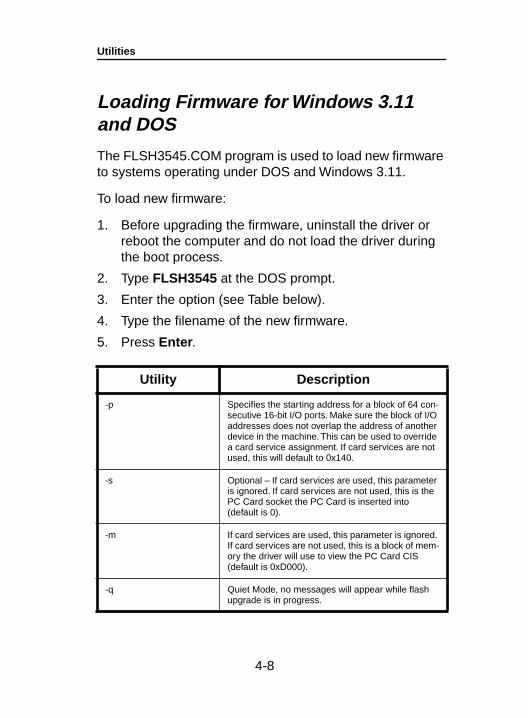
Loading Firmware for Windows 3.11 and DOS
The FLSH3545.COM program is used to load new firmware to systems operating under DOS and Windows 3.11.
To load new firmware:
1. Before upgrading the firmware, uninstall the driver or reboot the computer and do not load the driver during the boot process.
2. Type FLSH3545 at the DOS prompt.
3. Enter the option (see Table below).
4. Type the filename of the new firmware.
5. Press Enter .
Utility Description
-p Specifies the starting address for a block of 64 con-secutive 16-bit I/O ports. Make sure the block of I/O addresses does not overlap the address of another device in the machine. This can be used to override a card service assignment. If card services are not used, this will default to 0x140.
-s Optional – If card services are used, this parameter is ignored. If card services are not used, this is the PC Card socket the PC Card is inserted into (default is 0).
-m If card services are used, this parameter is ignored. If card services are not used, this is a block of mem-ory the driver will use to view the PC Card CIS (default is 0xD000).
-q Quiet Mode, no messages will appear while flash upgrade is in progress.
4-8
Error Messages and Trouble Shooting
5-1
Section 5
Error Messages and Trouble ShootingThe Wireless LAN Adapter provides LED messages and error codes. This section provides the general procedures for correcting common problems encountered when install-ing the Wireless LAN Adapter system.
Indicator LEDs
The Wireless LAN Adapter has two indicator LEDs (green and amber) located on the back of the card.
The green indicator is the Link Integrity/Power LED. It lights when the card is receiving power and flashes slowly when the Wireless LAN Adapter is linked with the network.
The amber indicator is the Link Activity LED. It flashes when the Wireless LAN Adapter is receiving or transmitting data or in a pattern to indicate an error condition.
See Tables 5.1 and 5.2 for an explanation of the LED Messages.
Error Messages and Trouble Shooting
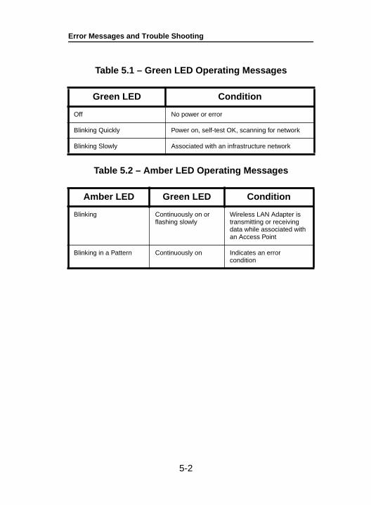
Table 5.1 – Green LED Operating Messages
Table 5.2 – Amber LED Operating Messages
Green LED Condition
Off No power or error
Blinking Quickly Power on, self-test OK, scanning for network
Blinking Slowly Associated with an infrastructure network
Amber LED Green LED Condition
Blinking Continuously on or flashing slowly
Wireless LAN Adapter is transmitting or receiving data while associated with an Access Point
Blinking in a Pattern Continuously on Indicates an error condition
5-2
Error Messages and Trouble Shooting
5-3
If Your Radio Fails to Establish Contact• Change your location or the location of the antenna by
a few feet and try again.
• Make sure the antenna is securely attached.
• Make sure the Wireless LAN Adapter is securely inserted in the slot.
• Make sure the receiving equipment is turned on and operating.
• Make sure the receiving equipment is properly con-nected to the host computer.
• Check that all parameters are set properly for both the Wireless LAN Adapter and the Aironet Access Point.
If the radio fails to establish contact, contact Aironet Technical Support for additional assistance:
Phone - (330) 664-7903 Fax - (330) 664-7990e-mail - [email protected]
http://www. aironet.com

Error Messages and Trouble Shooting
5-4
Wireless LAN Adapter Specifications
A-1
Appendix A
Wireless LAN Adapter Specifications
LAN Drivers Supported
Table A.1 – Supported Drivers
Protocol Operating System
ODI DOS based driver for Novell Netware
NDIS 2 MS DOS, Windows 3.xx
NDIS 3 Windows 95, Windows 98, Windows NT
Packet MS DOS, Windows 3.xx
Wireless LAN Adapter Specifications
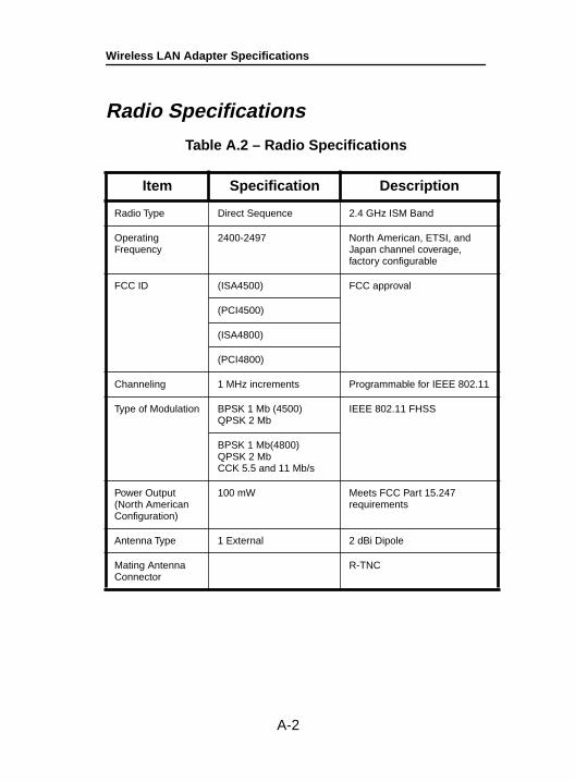
Radio Specifications
Table A.2 – Radio Specifications
Item Specification Description
Radio Type Direct Sequence 2.4 GHz ISM Band
Operating Frequency
2400-2497 North American, ETSI, and Japan channel coverage,factory configurable
FCC ID (ISA4500) FCC approval
(PCI4500)
(ISA4800)
(PCI4800)
Channeling 1 MHz increments Programmable for IEEE 802.11
Type of Modulation BPSK 1 Mb (4500)QPSK 2 Mb
IEEE 802.11 FHSS
BPSK 1 Mb(4800)QPSK 2 MbCCK 5.5 and 11 Mb/s
Power Output (North American Configuration)
100 mW Meets FCC Part 15.247 requirements
Antenna Type 1 External 2 dBi Dipole
Mating Antenna Connector
R-TNC
A-2
Wireless LAN Adapter Specifications
A-3
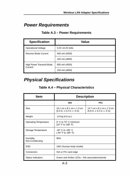
Power Requirements
Table A.3 – Power Requirements
Physical Specifications
Table A.4 – Physical Characteristics
Specification Value
Operational Voltage 5.0V ±0.25 Volts
Receive Mode Current 500 mA (4500)
150 mA (4800)
High Power Transmit Mode Current
800 mA (4500)
150 mA (4800)
Item Description
ISA PCI
Size 16.1 cm x 8.1 cm x 1.3 cm(6.3 in. x 3.2 in. x .5 in)
14.7 cm x 8.1 cm x 1.3 cm(5.8 in. x 3.2 in. x .5 in)
Weight .13 Kg (4.6 oz.)
Operating Temperature 0° C to 70° C minimum (32° F to 158° F)
Storage Temperature -40° C to +85° C (-40° F to 185° F)
Humidity, Non-Condensing
95%
ESD 15kV (human body model)
Connectors ISA or PCI card edge
Status Indicators Green and Amber LEDs – link association/activity

Wireless LAN Adapter Specifications
A-4
Using the WinDGS Utility
B-1
Appendix B
Using the WinDGS UtilityWinDGS is used to perform user level diagnostics on your Aironet Wireless LAN Adapter Card in the Windows 95, Windows 98, or Windows NT operating system environ-ment.
Commands MenuThe Commands Menu includes:
• Select Card
• Loading New Firmware
• Edit Properties
• Statistics
• Status
• Link test
• Site Survey
• Radio Off/On
• Exit
Select Card
This allows another installed Aironet Wireless LAN Adapter to be chosen. The property screens will change to reflect the parameters specific to each card type.
Commands Menu
Load New Firmware
See Section 4 – Utilities for more information on loading and upgrading firmware versions.
Edit Properties
WinDGS allows you to change the configuration parameters of your currently installed Wireless LAN Adapter. Depend-ing on the preferences you have set, WinDGS can save the current properties to the registry. See Save Properties Options for more information.
Statistics
The Statistics screen shows the current statistics from the Wireless LAN Adapter. Statistics are updated at the rate specified by the Screen Update Timer. Clear the current statistics by clicking on Reset . Exit the Statistics screen by clicking on OK, or by clicking on the X in the upper right hand corner of the dialog box.
Status
The Status screen shows the current status from the Wire-less LAN Adapter. Status is updated at the rate specified by the Screen Update Timer. Exit the Status screen by clicking on OK, or by clicking on the X in the upper right hand corner of the dialog box.
B-2
Commands Menu
Link Test
See Section 4 – Utilities for information on using link test.
Site Survey
See Section 4 – Utilities for information on using site survey.
Radio Off/On
Radio Off/On allows you to selectively turn off or on the power to the radio. Turning the radio off prevents all RF energy from being transmitted by the Wireless LAN Adapter.
Exit
Closes all windows and exits WinDGS.
B-3
Commands Menu
Options MenuThe Options Menu includes:
• Preferences
• Screen Update Timer
• Save Properties Options
Preferences
The WinDGS Preferences allow you to customize various parameters that control the operation of WinDGS. For example, you can set the rate at which the values are updated in the status and statistics screens via the Screen Update Timer. You can also set the Save Properties Options, which controls what is done with changes to the current settings.
Screen Update Timer
The Screen Update Timer controls how often the statistics and status screens are updated. The screen can be updated in one second increments, from once a second to once every 60 seconds. The default is once every five sec-onds. You can use either the edit box or the slider to change this value.
B-4
Edit Parameters
Save Properties Options
Use Save Properties Options to select the default opera-tions for saving the current adapter configuration. Choose either:
• Save Properties to the Registry : This option allows you to save the configuration to the Windows Registry. The configuration will be restored the next time you reboot.
• Save Properties to the Adapter : This option saves the current configuration to non-volatile memory in the adapter.
• Always Prompt the User : This option will prompt the user to save the current settings to the Registry. If the box is not checked, the operation will default to “Save Properties to the Registry”.
Edit ParametersThe Wireless LAN Adapter Parameters include:
• System Parameters
• Network Parameters
• RF Network Parameters
• Advanced (Infrastructure or Ad Hoc)
B-5
Edit Parameters
System Parameters
System parameters include:
• Name
• SSID
• Network Type (Infrastructure or Ad Hoc)
• Constant Awake Mode (CAM)
• Power Save Mode
• Fast Power Save Mode
Name
The station name is displayed in the table of connected devices on the Access Point. It provides a logical name to determine which machines are connected without having to memorize every MAC address. The name can be up to 16 characters.
SSID
The Service Set Identifier (SSID) controls access to a given wireless network. This value MUST match the SSID of any/all Access Points that you want to commu-nicate with. If the value does not match, access to the system is not granted. The SSID can be up to 32 char-acters (case sensitive).
Network type (Infrastructure Mode)
This mode is used to set up a connection to a wired network, such as Ethernet or Token Ring. This mode requires an Access Point to gain access to the wired network.
B-6
Edit Parameters
Network type (Ad Hoc Mode)
This mode is used to set up a small, temporary network between two or more computers. For example, you might set up an ad hoc network between computers in a conference room so users can share information in a meeting.
Constant Awake Mode (CAM)
Constant Awake Mode is the normal mode for desktop machines or other machines where power consumption is not an issue. It keeps the radio powered up continu-ously so there is little latency for responding to messages. This mode is recommended for devices where high availability is desired.
Power Save Mode
Power Save Mode is recommended for devices where power consumption is a major concern, such as small battery powered devices. Power Save Mode causes the Access Point to buffer incoming messages. The Wire-less LAN Adapter must wake up periodically and poll the Access Point to see if there are any buffered mes-sages waiting. The Wireless LAN Adapter can request each message and then go back to sleep.
Fast Power Save Mode
Fast Power Save Mode (Fast PSP Mode) switches between PSP and CAM based on network traffic. When retrieving a high number of packets, Fast PSP Mode will switch to CAM to retrieve the packets. Once the packets are retrieved, it switches back to PSP.
B-7
Edit Parameters
Network Parameters
User modifiable parameters are limited to the choice of MAC Address:
• Factory MAC Address : This is the default MAC address which is guaranteed to be unique. Unless you have a very good reason to define your own MAC address, it is STRONGLY RECOMMENDED that you use the factory MAC address.
• User Defined MAC Address : If you must define your own MAC address, you can enter it here. If you do not use a unique value, you may not be able to communi-cate to your wired network or you may disrupt other net-work devices. For this reason, it is STRONGLY RECOMMENDED that you use the factory MAC address. The MAC address is 12 hexadecimal digits. You do not need to use delimiters, but you can use spaces or the colon character.
RF Network Parameters
RF Network Parameters include:
• Fragment Threshold : This parameter defines a thresh-old above which the RF packet will be split up or frag-mented. If a packet is fragmented or transmission of part of it is interfered with, only the portion that was unsuccessful would need to be re-sent. The throughput will generally be lower for fragmented packets since the fixed packet overhead consumes a higher portion of the RF bandwidth.
B-8

Edit Parameters
• Data Retries : This parameter defines the number of times a packet will be re-sent if the initial transmission is unsuccessful. If the network protocol automatically re-tries itself, set this to a small value. A “bad” packet sta-tus will be sent up the protocol stack more quickly so the application can re-transmit the packet.
• Basic Data Rate : This parameter determines the data rate used to transfer all management frames by the cli-ent device when associated within a given Basic Ser-vice Set (BSS). When operating in Infrastructure Mode, this parameter should be set to correspond to the Access Point setting. When operating in Ad Hoc Mode, all stations should have the same setting.
• Supported Data Rates : This parameter specifies the data rates that will be supported by a given radio device in the BSS.
Model Allowable Selections
4500 1 Mbps or 2 Mbps
4800 1 Mbps, 2 Mbps, 5.5 Mbps, or 11 Mbps
Model Allowable Selections
4500 1 Mbps, 1_2 Mbps, or 2 Mbps
4800 1 Mbps, 1_2 Mbps, 1_5.5 Mbps, 1_11 Mbps2 Mbps, 2_5.5 Mbps, 2_11 Mbps,5.5 Mbps, 5.5_11 Mbps, or 11 Mbps
B-9
Edit Parameters
Advanced (Infrastructure)
The following parameters are contained in both the Infra-structure and Ad Hoc Modes:
• Specified Access Point
• RTS Threshold
• RTS Retry Limit
Specified Access Point
This parameter is the MAC address of the preferred Access Point you want to associate with. It is important to note that if you specify the Access Point, you MAY associate to another Access Point if the Specified Access Point is not found. If you roam out of range, you will probably associate with another Access Point. Setting a Specified Access Point will slow down the roaming process. Thus, for normal operation for the majority of users, leave this field blank.
RTS Threshold
This parameter controls what size data packet the low level RF protocol issues to an RTS packet. There are several trade-offs to consider when setting this parameter. Setting this parameter to a small value causes RTS packets to be sent more often, consuming more of the available bandwidth, therefore reducing the apparent throughput of other network packets. How-ever, the more often RTS packets are sent, the quicker the system can recover from interference or collisions. Refer to the IEEE 802.11 Standard for more information on the RTS/CTS mechanism.
B-10
Edit Parameters
RTS Retry Limit
This parameter controls the number of times the Wire-less LAN Adapter will re-send the RTS packet if it does not receive a CTS from the previously sent RTS packet. Setting this to a large value will decrease the available bandwidth whenever interference is encountered, but will make the system more immune to interference and collisions. Refer to the IEEE 802.11 Standard for more information on the RTS/CTS mechanism.
Advanced (Ad Hoc/IBSS)
In Ad Hoc Mode, you can also modify the following parameters:
• Channel
• Beacon Period
• Wake Duration
Channel
This parameter specifies the channel identifier the unit will use if it must start its own network. For all other situ-ations, the radio will scan for the proper frequency. See Appendix C for channel identifier parameters.
B-11
Edit Parameters
Beacon Period
This parameter specifies the duration between beacon packets that are used by IEEE 802.11 systems to synchronize the “hops” (change to another frequency). The beacon packet contains timing information and hop pattern information that is broadcast over the airwaves. Any station that can hear the beacon packet can then synchronize their internal timer so that it can hop at the correct time. The default beacon period is one-half of the dwell period so two beacons are transmitted per hop dwell period (default is 100 Kµsec). Refer to the IEEE 802.11 Standard for more information on the timing and scanning.
Wake Duration
This parameter specifies the amount of time per Hop Dwell Period that the adapter stays awake listening for data packets. This is only used in Power Save Mode.
B-12
Appendix C
Tested To ComplyWith FCC Standards
FOR HOME OR OFFICE USE
Appendix CManufacturers Federal Communication Commission Declaration of Conformity Statement
Models: ISA4500, ISA4800, PCI4500, PCI4800
Manufacturer:
Aironet Wireless Communications, Inc.3875 Embassy ParkwayAkron, OH 44333-8357330-664-7900
This device complies with Part 15 rules. Operation is subject to the following two conditions:
1) this device may not cause harmful interference, and 2) this device must accept any interference received, including interference that may cause undesired operation.
This equipment has been tested and found to comply with the limits of a Class B digital device, pursuant to Part 15 of the FCC Rules. These limits are designed to provide reasonable protection against harmful interference when the equipment is operated in a residential environment. This equip-ment generates, uses, and radiates radio frequency energy, and if not installed and used in accordance with the instructions, may cause harmful interference. However, there is no guarantee that interference will not occur. If this equipment does cause interference to radio or television reception, which can be determined by turning the equipment off and on, the user is encouraged to correct the interference by one of the following measures:
• Reorient or relocate the receiving antenna.• Increase separation between the equipment and receiver.• Connect the equipment into an outlet on a circuit different from which
the receiver is connected.• Consult the dealer or an experienced radio\TV technician.
User WarningThe Part 15 radio device operates on a non-interference basis with other devices
operating at this frequency. Any changes or modification to said product not expressly approved by Aironet could void the user’s authority to operate this
device.
C-1
Appendix C
Department of Communications—Canada Canadian Compliance Statement
This Class B Digital apparatus meets all the requirements of the Canadian Interference - Causing Equipment Regulations.
Cet appareil numerique de la classe B respecte les exigences du Reglement sur le material broilleur du Canada.
This device complies with RSS-210 of Industry of Canada. Operation is subject to the following two conditions: 1) this device may not cause harm-ful interference, and 2) this device must accept any interference received, including interference that may cause undesired operation.
The device is certified to the requirements of RSS-139-1 for 2.4 GHz spread spectrum devices. The use of this device in a system operating either partially or completely outdoors may require the user to obtain a license for the system according to the Canadian regulations. For further information, contact your local Industry Canada office.
C-2
Appendix C
European Telecommunication Standards InstituteStatement of ComplianceInformation to User
This equipment has been tested and found to comply with the European Telecommunications Standard ETS 300.328. This standard covers Wideband Data Transmission Systems referred in CEPT recommendation T/R 10.01.
This type accepted equipment is designed to provide reasonable protection against harmful interference when the equipment is operated in a commercial environment. This equipment generates, uses, and can radiate radio frequency energy, and if not installed and used in accordance with the instruction manual, may cause harmful interference to radio communications.
C-3
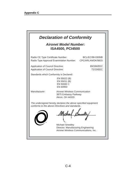
Appendix C
Declaration of Conformity
Aironet Model Number:ISA4500, PCI4500
Radio CE Type Certificate Number:Radio Type Approval Examiniation Number:
BCL/EC/98-0309/BCPC/ARLAN/DK/9815
Application of Council Directive:Application of Council Directive:
89/336/EEC72/23/EEC
Standards which Conformity is Declared:
Manufacturer: Aironet Wireless Communication3875 Embassy ParkwayAkron, OH 44333
Michael SmedleyDirector, Manufacturing EngineeringAironet Wireless Communications, Inc.
EN 55022 (B)EN 55011 (B)EN 50082-1EN 60950
®
The undersigned hereby declares the above specified equipmentconforms to the above Directives and standards.
C-4
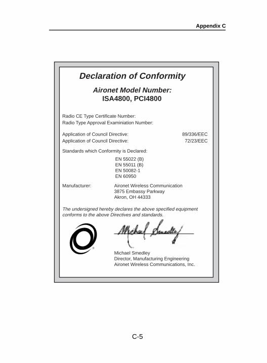
Appendix C
Declaration of Conformity
Aironet Model Number:ISA4800, PCI4800
Radio CE Type Certificate Number:Radio Type Approval Examiniation Number:
Application of Council Directive:Application of Council Directive:
89/336/EEC72/23/EEC
Standards which Conformity is Declared:
Manufacturer: Aironet Wireless Communication3875 Embassy ParkwayAkron, OH 44333
Michael SmedleyDirector, Manufacturing EngineeringAironet Wireless Communications, Inc.
EN 55022 (B)EN 55011 (B)EN 50082-1EN 60950
®
The undersigned hereby declares the above specified equipmentconforms to the above Directives and standards.
C-5

Appendix C
C-6
Appendix D
D-1
Appendix D
Technical Support
Communications
Use the following information to contact the Aironet Technical Support group:
Telephone - (330) 664-7903Fax - (330) 664-7990e-mail - [email protected]
Web Site
For additional product information and technical support, including the capability to download new firm-ware and drivers, use the Aironet web site at:
http://www.aironet.com