a turnstile conical-scan feed to 'improve tpacking-antenna ... · c , 't ,. _*. \ a...
TRANSCRIPT
c
, ' T
_*. , .
\
A TURNSTILE CONICAL-SCAN FEED TO 'IMPROVE TPACKING-ANTENNA I
. PERFORM'ANCE ON. ' APOLLO-INSTRUMENTED SHIPS
L
t .
1 I
GPO PRICE s CFSTI PRICE(S) $
I AUGUST 1967 < ?c D-Q
w 0
Hard copy (HC)
Microfiche (MF) 0 / B
L 2.
ff 653 July ,85 ,- i (PAGES)
I .
. ,
\ ,
(THRU)
/ (CODE)
G3jz ( C A T E O O ~ ~ )
I IX -5-3797 CR OR TMX OR AD NUMBER)
GODOARD SPACE / FLIGHT CENTER GREENBELT, MARYLAND
\
https://ntrs.nasa.gov/search.jsp?R=19670026450 2019-07-10T21:41:13+00:00Z
X-525-67-322
*
A TURNSTILE CONICAL-SCAN F E E D
TO IMPROVE TRACKING-ANTENNA PERFORMANCE
ON APOLLO-INSTRUMENTED SHIPS
Paul A. Lantz Advanced Development Division
August 1967
GODDARD SPACE FLIGHT CENTER Greenbelt, Maryland
A TURNSTILE CONICAL-SCAN FEED
TO IMPROVE TRACKING-ANTENNA PERFORMANCE
ON APOLLO-INSTRUMENTED SHIPS
Paul A. Lantz Advanced Development Division
ABST RAC T
This repor t descr ibes the design, development, and fab- rication of a turnsti le for use as a conical scanning feed in a 3 0 -foot paraboloidal reflector. On the Apollo-ins trumented ships te lemetry tracking antenna, this feed will replace a balanced conical logarithmic spiral now operating over the wide band f rom 2 2 5 to 2300 Mhz. The turnsti le operates over the nar row frequency band from 225 to 260 Mhz and provides both senses of c i rcu lar polarization simultaneously, resulting in superior performance over the nar rower frequency band of operation. It was necessary to remove a cavity backing the turnsti le, because of excessive drag on the dr ive unit. Some compromise in pr imary pat tern directivity resulted; however, performance i s superior to that of the existing feed. Mechanical design character is t ics permi t d i rec t r e - placement provided that the feed assembly i s refocused.
iii
CONTENTS
Page
INTRODUCTION . . . . . . . . . . . . . . . . . . . . . . . . . . . . . . . . 1
BACKG .ROU ND. . . . . . 3
ELECTRICAL DESIGN . . . . . . . . . . . . . . . . . . . . . . . . . . . 3
Choice of Feed Type . . . . . . . . . . . . . . . . . . . . . . . . . . P r i m a r y Pat terns . . . . . . . . . . . . . . . . . . . . . . . . . . . . 4 Reflector Blockage Effects. . . . . . . . . . . . . . . . . . . . . . 5
Gain and Efficiency Calculations . . . . . . . . . . . . . . . . . .
3
Secondary Pa t te rn Predict ions . . . . . . . . . . . . . . . . . . . 8 Feed Displacement Computation . . . . . . . . . . . . . . . . . . 8
12 Defocusing Effects . . . . . . . . . . . . . . . . . . . . . . . . . . . 17
MECHANICAL DESIGN. . . . . . . . . . . . . . . . . . . . . . . . . . . 21
Size Limitations. . . . . . . . . . . . . . . . . . . . . . . . . . . . . 21 Feed Rotation Drive . . . . . . . . . . . . . . . . . . . . . . . . . . 21
Measured Weights . . . . . . . . . . . . . . . . . . . . . . . . . . . 24 Dynamic Balance . . . . . . . . . . . . . . . . . . . . . . . . . . . . 24 Ins tallation Procedure. . . . . . . . . . . . . . . . . . . . . . . . . 24
Aerodynamic Drag Resis tance . . . . . . . . . . . . . . . . . . . 21
PERFORMANCE RESULTS . . . . . . . . . . . . . . . . . . . . . . . . 28
P r i m a r y Pa t te rn Measurements . . . . . . . . . . . . . . . . . . 2 8 Axial R a t i o . . . . . . . . . . . . . . . . . . . . . . . . . . . . . . . . 31 VSWR . . . . . . . . . . . . . . . . . . . . . . . . . . . . . . . . . . . . 31 Isolation. . . . . . . . . . . . . . . . . . . . . . . . . . . . . . . . . . 32 Predicted Secondary Pa t t e rn . . . . . . . . . . . . . . . . . . . . 32
SUMMARY . . . . . . . . . . . . . . . . . . . . . . . . . . . . . . . . . . . 34
ACKNOWLEDGMENTS . . . . . . . . . . . . . . . . . . . . . . . . . . . 35
V
ILLUSTRATIONS
Figure Page
1 Apollo -Ins t rument ed Ships Tracking Telemet ry (4-1) Antenna. . . . . . . . . . . . . . . . . . . . . . . . . . . . . 2
2 Space Attenuation. . . . . . . . . . . . . . . . . . . . . . . . . . 5
3 Aperture Plane Radius vs Angle Off Axis of Reflector. . 6
4 P r i m a r y Pa t te rn Adjusted To Include Space Attenuation . . . . . . . . . . . . . . . . . . . . . . . . . . . . . . 7
5 On-Axis View of Antenna Aperture . . . . . . . . . . . . . . 9
6 Secondary Pa t t e rn Corrected F o r Aperture Blockage (Cavity-Backed Turnst i le) . . . . . . . . . . . . . . . . . . . . 10
7 Calculated Secondary Pa t te rn With Scanning Action (Cavity-Backed Turnst i le) , . . . . . . . . . , . . . . . . . , . 11
8 Geometric Analysis of Feed Offset . . . . . . . . . . . . , . 13
9 P r i m a r y Pa t te rn Adjusted To Include Space Attenuation . . . . . . . . . . , . . . . . . . . . . . . . . . . . . . 16
10 P r i m a r y Pa t t e rn Field Components (Feed 2 Feet Outside Focus). . . . . , . . . . . . . . . . . . . . . . . . . . . . 18
11 Secondary Pa t t e rn Field Components (Feed 2 Feet Outside Focus). . . . . . . . , . . . . . . . . . . . . . . . . , . . 19
12 Calculated Secondary Pa t te rn (Feed 2 Fee t Outside Focus) . . . . . . . . . . . . , . . . . . . . . . . . . . . . . . . . . 20
13 Turnst i le Feed With Cavity Backing. . . . . . . . , . . . . . 2 2
14 Turnst i le Feed - Final Configuration Cavity Removed. . 23
15 Feed In Dynamic Balancing Machine, Rea r View . . . . . 25
vi
Figure Page
16 Feed In Dynamic Balancing Machine. F ron t View . . . . . 26
17 Vibration Severity Nomograph . . . . . . . . . . . . . . . . . 27
18 Coordinate System F o r P r imary Pa t t e rns . . . . . . . . . . 29
19 225-Mhz Measured P r i m a r y Pa t te rn . . . . . . . . . . . . . 30
20 237-8-Mhz Measured P r imary Pa t t e rn . . . . . . . . . . . . 30
21 260-Mhz Measured P r i m a r y Pa t te rn . . . . . . . . . . . . . 31
22 Calculated Secondary Pa t te rn W i t h Scanning Action (Cavity Removed F r o m Turnsti le) . . . . . . . . . . . . . . . 33
TABLES
Table Page
1 Reflector Edge Illumination . . . . . . . . . . . . . . . . . . . 29
2 Measured Voltage Standing-Wave Ratio (VSWR) . . . . . . 32
3 Comparison of Turnsti le and Conical Log Spiral Feeds (237.8 Mhz) . . . . . . . . . . . . . . . . . . . . . . . . . 35
vii
.
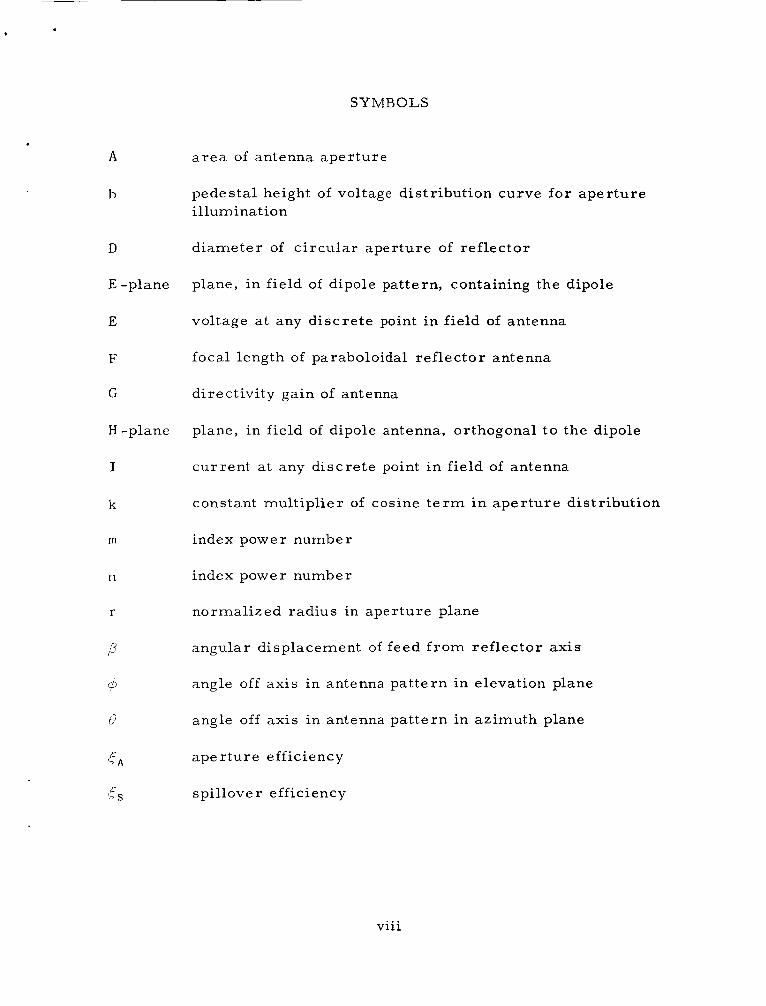
SYMBOLS
. A
b
D
E -plane
E
F
C
H -plane
I
k
m
n
r
P
a r e a of antenna aperture
pedestal height of voltage distribution curve for aper ture illumination
diameter of c i rcular aperture of reflector
plane, in field of dipole pattern, containing the dipole
voltage a t any discrete point in field of antenna
focal length of paraboloidal reflector antenna
directivity gain of antenna
plane, in field of dipole antenna, orthogonal to the dipole
current a t any discrete point in field of antenna
constant multiplier of cosine t e r m i n aper ture distribution
index power number
index power number
normalized radius in aperture plane
angular displacement of feed f rom reflector axis
angle off axis in antenna pat tern in elevation plane
angle off axis in antenna pat tern in azimuth plane
aper ture efficiency
spillover efficiency
... V l l l
A TURNSTILE CONICAL-SCAN F E E D TO IMPROVE TRACKING-ANTENNA PERFORMANCE
ON APOL LO -INS T RUMEN TE D SHIPS
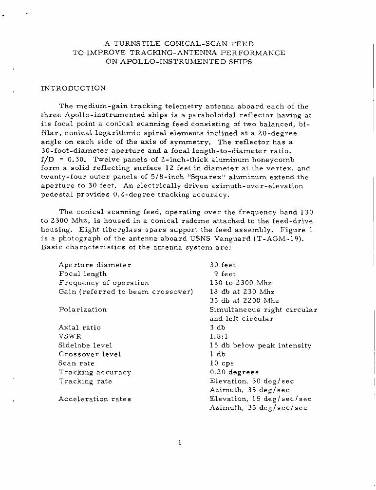
INTRODUCTION
The medium-gain tracking telemetry antenna aboard each of the three Apollo-instrumented ships is a paraboloidal ref lector having at i t s focal point a conical scanning feed consisting of two balanced, bi- filar, conical logarithmic sp i ra l elements inclined at a 20-degree angle on each side of the axis of symmetry. The reflector has a 30-foot-diameter aper ture and a focal length-to-diameter ratio, f/D = 0.30. Twelve panels of 2-inch-thick aluminum honeycomb fo rm a solid reflecting surface 1 2 feet in diameter a t the ver tex, and twenty-four outer panels of 5/8-inch "Squarex'' aluminum extend the aper ture to 30 feet . An electrically driven azimuth-over-elevation pedestal provides 0.2-degree tracking accuracy,
The conical scanning feed, operating over the frequency band 130 to 2300 Mhz, i s housed i n a conical radome attached to the feed-drive housing. Eight f iberglass spa r s support the feed assembly. Figure 1 i s a photograph of the antenna aboard USNS Vanguard (T-AGM-19). Basic charac te r i s t ics of the antenna system a r e :
Aperture diameter Focal length Frequency of ope ration Gain ( r e fe r r ed to beam crossover)
Polarization
Axial ratio VSWR Sidelobe level Crossover level Scan ra te T racking a c curacy Tracking ra te
Acceleration r a t e s
30 feet 9 feet
130 to 2300 Mhz 18 db at 230 Mhz 35 db at 2200 Mhz Simultaneous right c i rcu lar and left c i rcu lar 3 db 1.8:l 15 db below peak intensity 1 db
0.20 degrees Elevation, 30 deg/sec Azimuth, 35 deg/sec Elevation, 15 deg / sec / sec Azimuth, 35 deg / sec / sec
10 cps
1
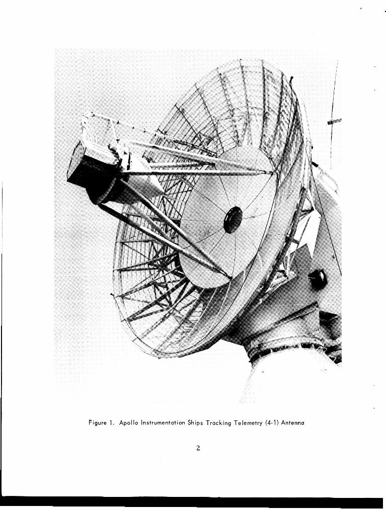
Figure 1. Apollo Instrumentation Ships Tracking Telemetry (4-1) Antenna
2

BACKGROUND
The reflector now uses a conical scanning feed which consists of a pa i r of balanced bi-filar conical logarithmic sp i ra l s , one wound in the right c i rcu lar sense and one in the left c i rcu lar sense. these off-axis sp i ra l s about the reflector axis of symmetry provides conical scanning capability. the frequency band 130 to 2300 Mhz, in o rde r to meet Apollo mission requirements in the 225- to 260-Mhz band a s well a s Department of Defense requirements at L- and S-band frequencies.
Rotation of
This feed is designed to operate over
Performance of the antenna system can be significantly improved for Apollo mission requirements by retrofitting the reflector with a feed designed for operation over the narrow band f rom 225 to 260 Mhz and by properly focusing the feed for these frequencies. descr ibes the design, development, and performance of a retrofit feed of this type.
This repor t
ELECTRICAL DESIGN
Choice of Feed Tvpe
The conical log-spiral antenna now in use has performance char - 1 ac ter i s t ics
operation is required. dependent of frequency, and impedance i s constant when special ca re i s used in designing the balun and base terminal load. unidirectional, without the need of a ground plane, going in the direction of the apex, and i s polarized circularly.
which make it a good feed f o r re f lec tors when broadband Pa t te rn shape and directivity a r e relatively in-
The radiation i s
Another c i rcular ly polarized feed for ref lectors i s the turnsti le in which pa i r s of c rossed dipoles a r e fed 90 degrees out of phase. pattern, which i s bidirectional, can readily be made unidirectional by placing a reflector behind the dipoles. quirements of the Apollo mission, the turnsti le i s considered to be a super ior feed, because of i t s simplicity. The typical 2: l variation in E - and H-plane beamwidth can be eliminated by locating the turnsti le in a cavity.
The
To meet the narrowband r e -
Ellipticity i s thereby minimized for angles off the axis of
Dyson, John D., ‘@The Characteristics and Design of The Conical Log Spiral Antenna, Univer- s i ty of Illinois, Antenna Laboratory Report 65-4, May 1965
1
3
the turnstile. Mhz frequency band, was available as a catalogue item.2 necessary hybrid junction3 was available for use in combining l inear polarizations to provide simultaneous right- and left -c i rcular ly po- lar ized outputs. It was necessary only to design a suitable device for attaching the feed to the conical scanning dr ive, and to establish the necessary physical displacement, to produce the des i red conical scan pattern.
Such a device, designed specifically for the 215- to 260- Moreover, the
Pr imary Pa t te rns
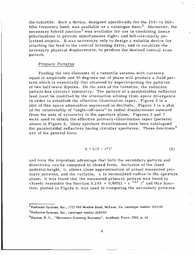
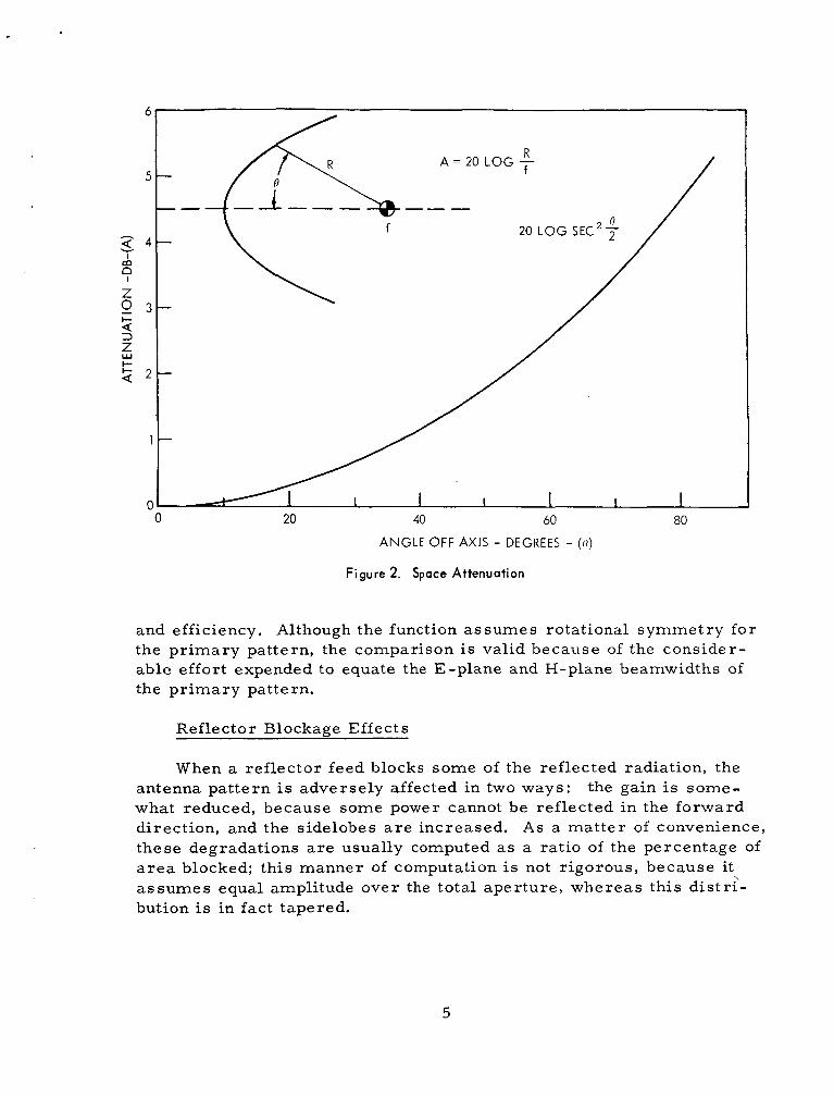
Feeding the two elements of a turnst i le antenna with cu r ren t s equal in amplitude and 90 degrees out of phase will produce a field pat- t e r n which is essentially that obtained by superimposing the pat terns of two half-wave dipoles. pattern has c i rcu lar symmetry. The pat tern of a paraboloidal ref lector feed must b e modified by the attenuation ar is ing f rom space divergence in order to establish the effective illumination taper . plot of this space attenuation expressed in decibels. of the relationship of "angle-off-axis" to radial displacement outward f r o m the axis of symmetry in the aper ture plane. were used to obtain the effective primary-il lumination taper (pattern) shown in Figure 4. Many aper ture distributions have been catalogued for paraboloidal ref lectors having c i r cu la r aper tures . a r e of the general fo rm
On the axis of the turnst i le , the radiation
Figure 2 i s a F igure 3 is a plot
F igures 2 and 3
These functions
b + k ( l - rm)" (1 )
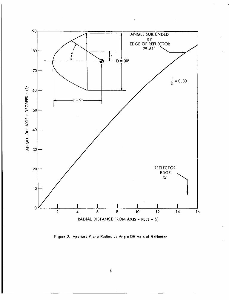
and have the important advantage that both the secondary pat tern and directivity can be computed in closed form. pedestal height, b, allows close approximation of actual measu red pr i - m a r y patterns, and the variable, plane. It was found that the measured p r imary pattern was found to closely resemble the function 0.195 + 0.805(1 - r 1 .51 ) 2 and this func- tion, plotted in Figure 4, was used in computing the secondary pat terns
Inclusion of the fixed
r, is normalized radius in the aper ture
~
2Radiation Systems, Inc., 1755 Old Meadow Road, McLean, Va. catalogue number 1623-02 3Radiation Systems, Inc., catalogue number 2631-02
4Hanson, R. C . , "Microwave Scanning Antennas", Academic Press, 1964, p. 64
4
/ R
20 40 60 80
ANGLE OFF AXIS - DEGREES - ( 0 )
Figure 2. Space Attenuation
and efficiency. Although the function assumes rotational symmetry for the pr imary pattern, the comparison is valid because of the consider- able effort expended to equate the E-plane and H-plane beamwidths of the pr imary pattern.
Reflector Blockage Effects
When a reflector feed blocks some of the reflected radiation, the antenna pat tern is adversely affected in two ways: the gain is some- what reduced, because some power cannot be reflected in the forward direction, and the sidelobes a r e increased. As a ma t t e r of convenience, these degradations a r e usually computed a s a ratio of the percentage of a r e a blocked; this manner of computation is not r igorous, because it a s sumes equal amplitude over the total aper ture , whereas this distr?- bution is in fact tapered.
5
90
80
70
- E 60
I m W W
t5 E 50
c" X Q
I
40 8 w -1 0 Z Q 30
20
10
0
A N G L E SUBTENDED BY
EDGE OF REFLECTOR
15'
2 4 6 8 10 12 14 16
RADIAL DISTANCE FROM AXIS - FEET - (r)
Figure 3. Aperture Plane Radius vs Angle Off-Axis of Reflector
6

1 .o
0 . 9
0.8
0.7 v, I- G , 0.6 I
Z E 0.5
n w > 0.4
4
5 W
v,
A
LL W
I- - W cr:
0.3
0.2
0.1
0
235 MHZ
f/D = 9/30 = 0 . 3
I ( r )=0 .195 t
MEASURED ' PRIMARY PATTERN
.805 (1 -
b =
I I I I I I 2 4 6 8 10 12 14
RADIAL DISTANCE FROM AXIS-FEET (r)
Figure 4. Primary Pattern Adiusted To Include Space Attenuation
7
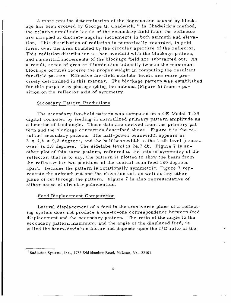
A more precise determination of the degradation caused by block- age has been evolved by George G. Chadwick. * In Chadwick's method, the relative amplitude levels of the secondary field f r o m the ref lector a r e sLmpled at discrete angular increments in both azimuth and eleva- tion. form, over the a r e a bounded by the c i rcu lar aper ture of the reflector. This radiation distribution i s then overlaid with the blockage pattern, and numerical increments of the blockage field a r e subtracted out. a resul t , a reas of grea te r illumination intensity (where the maximum blockage occurs) receive the proper weight in computing the resultant far-field pattern. Effective far-field sidelobe levels a r e m o r e pre- cisely determined in this manner. for this purpose by photographing the antenna (F igure 5) f rom a po- sition on the reflector axis of symmetry.
This distribution of radiation is numerically recorded, in gr id
A s
The blockage pat tern was established
Secondary Pa t te rn Predictions
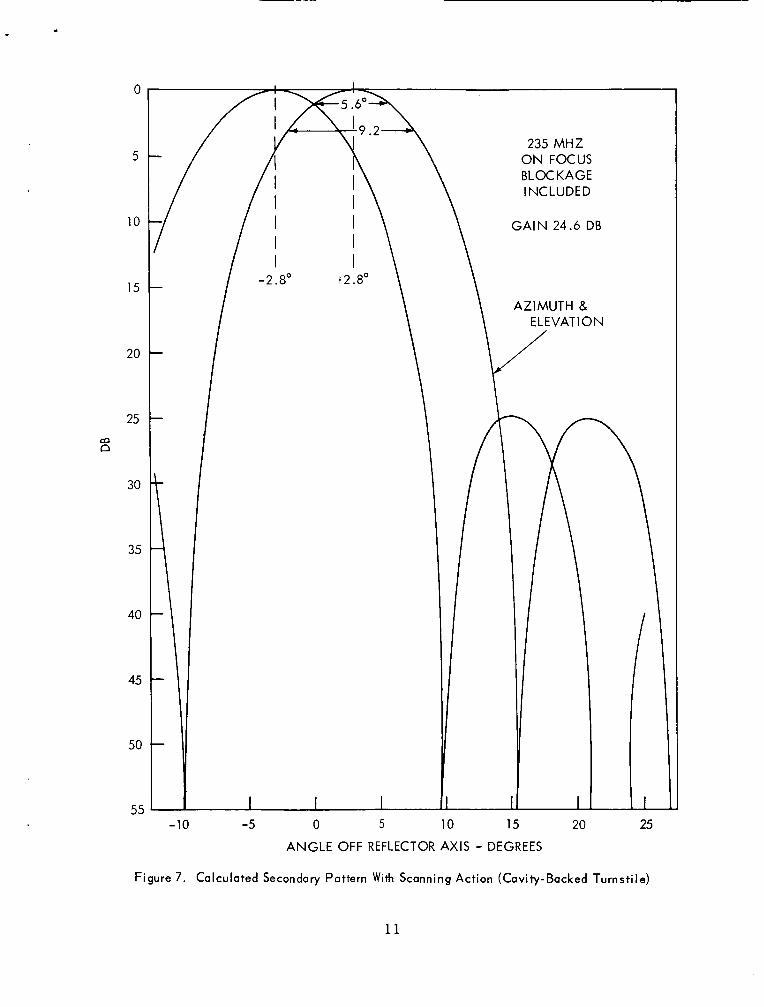
The secondary far-field pattern was computed on a GE Model T-35 digital computer by feeding in normalized p r imary pat tern amplitude as a function of feed angle. These data a r e derived f rom the pr imary pat- t e r n and the blockage correct ion described above. sultant secondary pattern. 2 x 4.6 = 9.2 degrees , and the half beamwidth a t the 1-db level ( c r o s s - over) is 2.8 degrees . other plot of this same pattern, r e f e r r ed to the axis of symmetry of the ref lector ; that is to say, the pat tern i s plotted to show the beam f r o m the reflector for two positions of the conical scan feed 180 degrees apart . Because the pattern is rotationally symmetr ic , Figure 7 rep- resents the azimuth cut and the elevation cut, a s well as any other plane of cut through the pattern. e i ther sense of c i rcu lar polarization.
Figure 6 is the r e - The half-power beamwidth appears a s
The sidelobe level i s 24.7 db. Figure 7 is an-
Figure 7 is a l so representative of
Feed Displacement Computation
Lateral displacement of a feed in the t r ansve r se plane of a ref lect- ing system does not produce a one-to-one correspondence between feed displacement and the secondary pattern. The ratio of the angle to the secondary pat tern maximum, and the angle of the displaced feed, is called the beam-deviation factor and depends upon the f / D ratio of the
*Radiation Systems, Inc., 1755 Old Meadow Road, McLean, Va. 22101
8
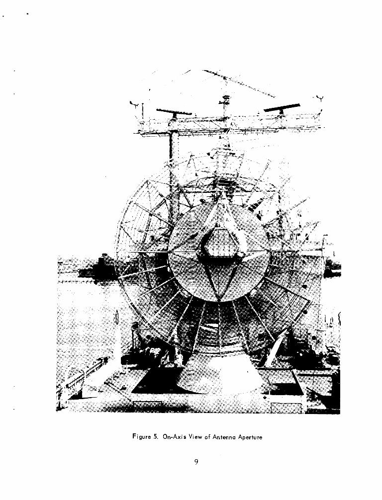
Figure 5. On-Axis View of Antenna Aperture
9 I

20
25
m n
30
35
40
45
50
55
10 -
15 -
I
0 5 10
235 MHZ
/
15 20 25 30
ANGLE OFF BEAM AXIS - DEGREES
Figure 6. Secondary Pattern Corrected For Aperture Blockage (Cavity-Backed Turnstile)
1 0
0
5
10
15
20
25 m n
30
35
40
45
50
55
235 M H Z ON FOCUS BLOCKAGE INCLUDED
G A I N 24.6 DB
AZIMUTH & E LEVAT I 0 N
I I I -10 -5 0 5 10 15 20 25
ANGLE OFF REFLECTOR AXIS - DEGREES
Figure 7. Calculated Secondary Pattern With Scanning Action (Cavity-Backed Turnstile)
11
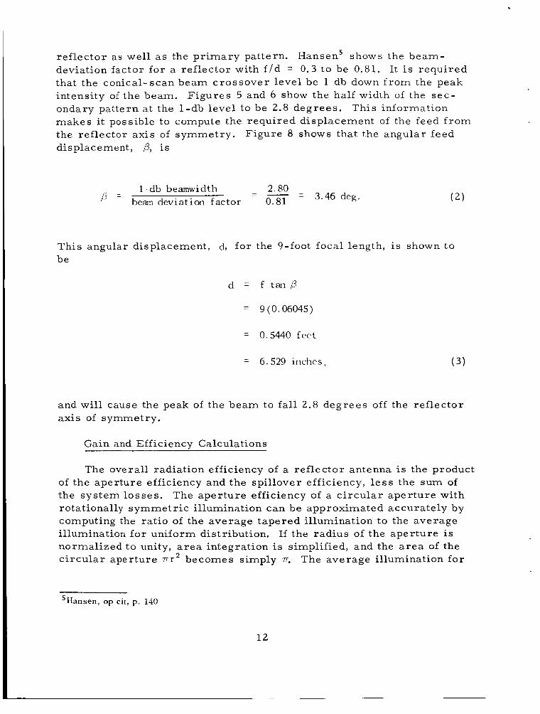
reflector as well as the pr imary pattern. Hansen' shows the beam- deviation factor for a reflector with f / d = 0 . 3 to be 0.81. that the conical-scan beam crossover level be 1 db down f rom the peak intensity of the beam. ondary pattern at the l -db level to be 2.8 degrees . makes it possible to compute the required displacement of the feed f rom the reflector axis of symmetry. displacement, ,B, i s
It i s required
Figures 5 and 6 show the half width of the sec - This information
Figure 8 shows that the angular feed
2.80 = beam deviation factor 0.81
- - - 3.46 deg. - - l -db beamwidth
This angular displacement, be
d, for the 9-foot focal length, i s shown to
d = f t a n b
= g(0.06045)
0.5440 feet
= 6.529 inches, ( 3 )
and will cause the peak of the beam to fall 2.8 degrees off the reflector axis of symmetry.
Gain and Efficiency Calculations
The overall radiation efficiency of a reflector antenna i s the product of the aperture efficiency and the spillover efficiency, l e s s the sum of the system losses . The aper ture efficiency of a c i rcu lar aper ture with rotationally symmetr ic illumination can be approximated accurately by computing the ratio of the average tapered illumination to the average illumination for uniform distribution. If the radius of the aper ture is normalized to unity, a r e a integration is simplified, and the a r e a of the c i rcu lar aperture 7rr2 becomes simply 7. The average illumination for
'Hansen, op cit, p. 140
1 2

Figure 8. Geometric Analysis of Feed Offset
f/D = 0.30 BEAM DEVIATION FACTOR = 0.81 1 -db BEAMWI DTH = 2 .80°
2.80
0.81 p = - = 3.46'
d = f tan p = 9 (0.06045) = 0.544 FEET = 6 5 2 9 INCHES
the tapered distribution i s then
1 3

1
I = 2 1 r I ( r ) d r .
The average illumination for the uniform distribution i s
1
I ,2 = Ll 2- r r r12 ( r )d r w>2 1
12 2 1 r 1 2 ( r ) d r
The aperture efficiency i s then the rat io of I2 to I t o r
(5 )
The numerical values for the parameters of I2 r (F igure 4) to be
were shown e a r l i e r
I ( r ) = 0.195 + 0.805(1 - r 1 . 5 1 ) 2 .
Substituting in (8) and performing the integration
0.7731, 0.0813 - - - -
C A - 0.1052
( 9 )
hence the aperture efficiency is 77.31 percent. duces this efficiency to 68.97 percent.
Aperture blocking r e - The spillover efficiency was
14
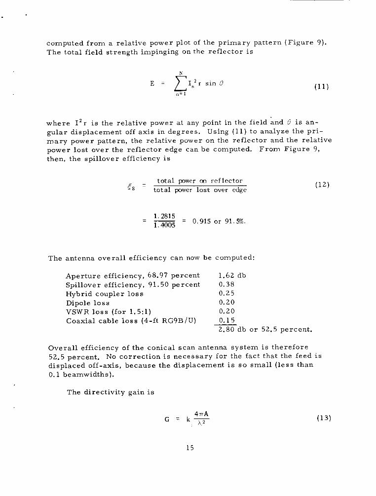
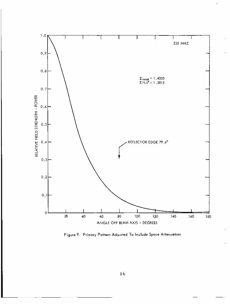
computed f r o m a relative power plot of the pr imary pattern (Figure 9) . The total field strength impinging on the reflector i s
N
E = C I : r s in e "= 1
where I Z r i s the relative power at any point in the field and 8 i s an- gular displacement off axis in degrees. mary power pattern, the relative power on the reflector and the relative power lost over the reflector edge can be computed. then, the spillover efficiency is
Using (11) to analyze the p r i -
F r o m Figure 9,
- total power on reflector 6 s - total power lost over edge
1.2815 1.4005 - 0.915 or 91.5%. -
The antenna overall efficiency can now be computed:
Aperture efficiency, 68.97 percent Spillover efficiency, 91.50 percent 0.38 Hybrid coupler loss 0.25
1.62 db
Dipole lo s s 0.20 VSWR los s (for 1.5:l) 0.20 Coaxial cable loss (4-ft RG9B/U) 0.15
2.80 db o r 52.5 percent.
Overall efficiency of the conical scan antenna system i s therefore 52.5 percent. displaced off-axis, because the displacement i s so smal l ( l e s s than 0.1 beamwidths).
No correct ion is necessary for the fact that the feed i s
The directivity gain is
4 T A G = k-
A 2
15
1 .o
0.9
0.8
0.7
rx W
3 0.6
I El
z, QL 0.5
n
w 0.4 >
+ Ln
-I w U -
- I-
4 W ai
0 .:
0.2
0.
C
1 I 1 I I I 235 MHZ
REFLECTOR EDGE 79.6'
20 40 60 80 100 120 1 40 160 180
ANGLE OFF BEAM AXIS - DEGREES
Figure 9. Primary Pattern Adiusted To Include Space Attenuation
16
where A is aper ture a rea , and k is efficiency. ficiency, the decibel equivalent gain at 235 Mhz is
F o r 52.5-percent ef-
= 24.2 db.
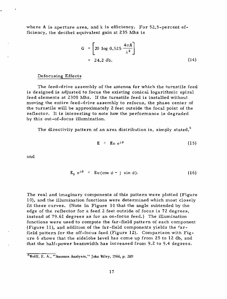
Defocusing Effects
The feed-drive assembly of the antenna for which the turnsti le feed i s designed is adjusted to focus the existing conical logarithmic sp i ra l feed elements at 2300 Mhz. If the turnsti le feed is installed without moving the ent i re feed-drive assembly to refocus, the phase center of the turnst i le will be approximately 2 feet outside the focal point of the reflector. It is interesting to note how the performance is degraded by this out-of -focus illumination.
The directivity pat tern of an a r e a distribution is, simply stated,6
and
E, e j 4 = Eo(cos 4 - j sin 4). (16)
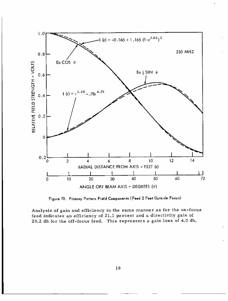
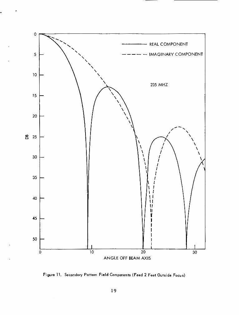
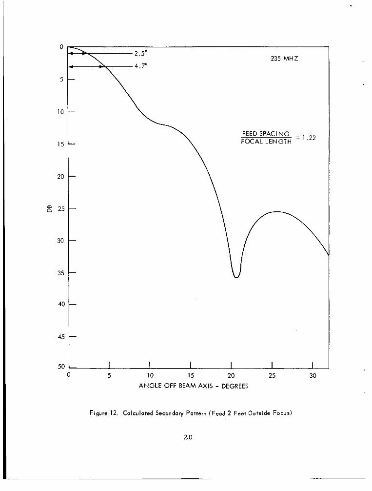
The r e a l and imaginary components of th is pat tern were plotted (Figure l o ) , and the illumination functions were determined which most closely fit these curves. (Note in Figure 1 0 that the angle subtended by the edge of the reflector for a feed 2 feet outside of focus i s 72 degrees , instead of 79.61 degrees as for an on-focus feed.) The illumination functions were used to compute the far-field pat tern of each component (F igure l l ) , and addition of the far-field components yields the far- field pat tern for the off-focus feed (Figure 12) . Comparison with Fig- u r e 6 shows that the sidelobe level has come up f rom 25 to 12 db, and that the half-power beamwidth has increased f rom 9.2 to 9.4 degrees .
6Wolff, E. A., ‘‘Antenna Analysis,” John Wiley, 1966, p. 289
1 7
1 .o
0.8
v, t- G , 0.6 I 5 Z f5 0.4
n w
w
v,
1
L L
0.2 - t-
4 w ai
0
0 .: 2 4 6 8 10 12 14
RADIAL DISTANCE FROM AXIS - FEET (r)
1 I I 1 I I I I1 0 10 20 30 40 50 60 72
ANGLE OFF BEAM AXIS - DEGREES ( e )
Figure 10. Primary Pattern Field Components (Feed 2 Feet Outside FOCUS)
Analysis of gain and efficiency in the same manner as for the on-focus feed indicates an efficiency of 21.1 percent and a directivity gain of 20.2 db for the off-focus feed. This represents a gain loss of 4.0 db.
18
0
5
10
15
20
25
30
35
40
45
50
\ \ \ \ 235 MHZ
Y / /- \ / \
ANGLE OFF BEAM AXIS
Figure 11. Secondary Pattern Field Components (Feed 2 Feet Outside Focus)
19
0
5
10
15
20
25
30
35
40
45
50
235 M H Z
FEED SPACING FOCAL LENGTH = .22
0 5 10 15 20 25 30 ANGLE OFF BEAM AXIS - DEGREES
Figure 12. Calculated Secondary Pattern (Feed 2 Feet Outside FOCUS)
20
ME CHANICAL DESIGN
Size Limitations
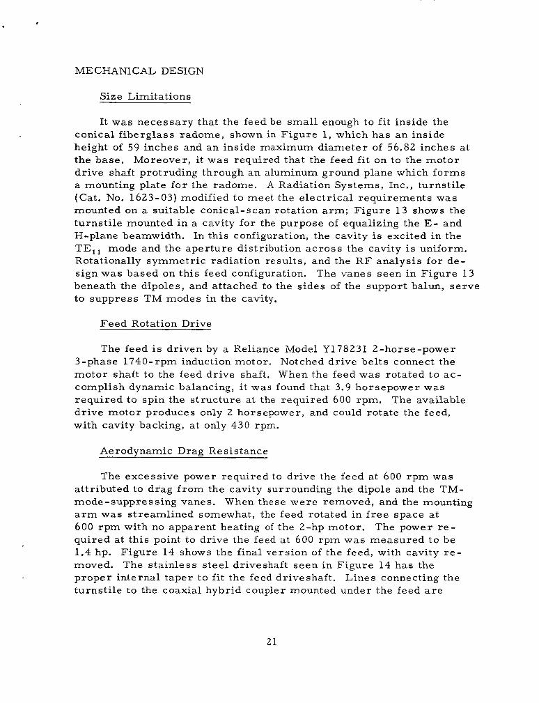
It was necessary that the feed be small enough to fit inside the conical f iberglass radome, shown in Figure 1, which has an inside height of 59 inches and an inside maximum diameter of 56.82 inches at the base. dr ive shaft protruding through an aluminum ground plane which forms a mounting plate fo r the radome. A Radiation Systems, Inc., turnsti le (Cat. No. 1623-03) modified to meet the e lec t r ica l requirements was mounted on a suitable conical-scan rotation a r m ; Figure 13 shows the turnst i le mounted in a cavity for the purpose of equalizing the E - and €3-plane beamwidth. In this configuration, the cavity i s excited in the TE,, mode and the aper ture distribution a c r o s s the cavity is uniform. Rotationally symmetr ic radiation results, and the R F analysis for de- sign was based on this feed configuration. beneath the dipoles, and attached t o the s ides of the support balun, s e rve to suppress TM modes in the cavity.
Moreover, it was required that the feed fi t on to the motor
The vanes seen in Figure 13
Feed Rotation Drive
The feed is driven by a Reliance Model Y178231 2-horse-power Notched dr ive belts connect the 3-phase 1740-rpm induction motor.
motor shaft to the feed drive shaft. When the feed was rotated to ac- complish dynamic balancing, i t was found that 3.9 horsepower was requi red to spin the s t ruc ture at the required 600 rpm. dr ive motor produces only 2 horsepower, and could rotate the feed, with cavity backing, at only 430 rpm.
The available
Aerodvnamic Drag Resistance
The excessive power required to drive the feed at 600 rpm was attr ibuted to drag f r o m the cavity surrounding the dipole and the TM- mode-suppressing vanes. When these were removed, and the mounting a r m was streamlined somewhat, the feed rotated in f r e e space a t 600 r p m with no apparent heating of the 2-hp motor. The power r e - quired a t this point to drive the feed a t 600 rpm was measured to be 1.4 hp. moved. proper internal taper to fit the feed driveshaft. turnst i le to the coaxial hybrid coupler mounted under the feed a r e
Figure 14 shows the final version of the feed, with cavity r e - The stainless s tee l driveshaft seen in Figure 14 has the
Lines connecting the
2 1
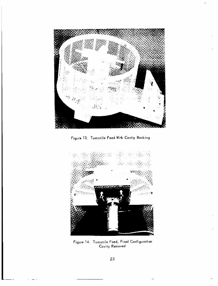
Figure 13. Turnstile Feed W i t h Cavity Backing
Figure 14. Turnstile Feed, Final Configuration Cavity Removed
22
RG-SB/U, and the outputs f r o m the coupler a r e fed down through the hollow shaft t o mate with existing Type N connectors on the two-channel ro ta ry joint.
Measured Weights
Weights of var ious components of the feed assembly, measured on a platform scale, a r e as follows;
Turnsti le element Ground plane Support s t ructure Drive shaft Hybrid coupler Counterweights Cables and hardware Radome spacing ring
Total weight
5.5 pounds 8.0
27.5 15.5
1.5 15.0
3.5 10.9 87.4 pounds
This weight is 12.6 pounds l e s s than the existing dual conical logarith- m i c sp i ra l feed, which weighs 100 pounds.
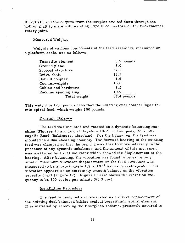
Dynamic Balance
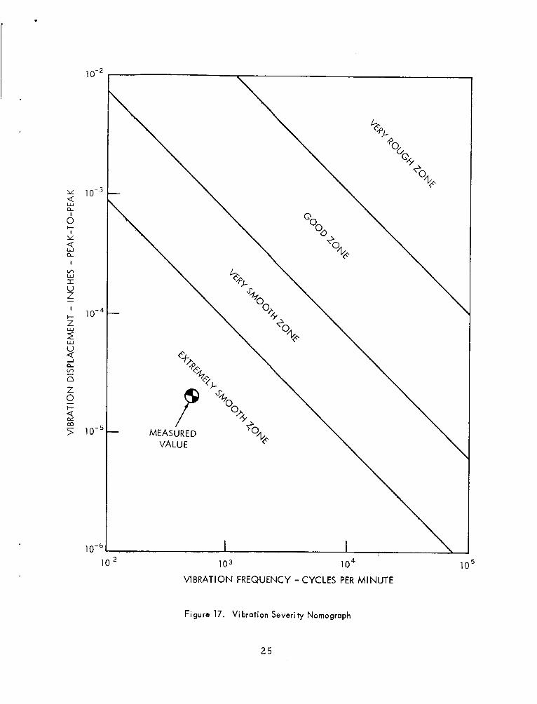
The feed was mounted and rotated on a dynamic balancing ma- chine (F igures 15 and 16), a t Keystone Elec t r ic Company, 2807 An- napolis Road, Baltimore, Maryland. F o r the balancing, the feed was mounted in a dual-bearing housing. The forward bearing of the rotating feed was clamped so that the bearing was f r e e to move laterally in the presence of any dynamic unbalance, and the amount of this movement was measured by a dial indicator which showed the displacement a t the bearing. After balancing, the vibration was found to be extremely small: maximum vibration displacement on the feed s t ruc ture was measu red to be approximately 1.9 x 10'' inches peak-to-peak. vibration appears as an extremely smooth balance on the vibration severi ty chart (F igure 17). quency to be 500 cycles p e r minute ( 8 3 . 3 cps).
This
Figure 17 a l so shows the vibration f r e -
Install at ion P r o c e dur e
The feed is designed and fabricated a s a direct replacement of the existing dual balanced bifi lar conical logarithmic sp i r a l element. It is installed by removing the fiberglass radome, presently secured t o
23
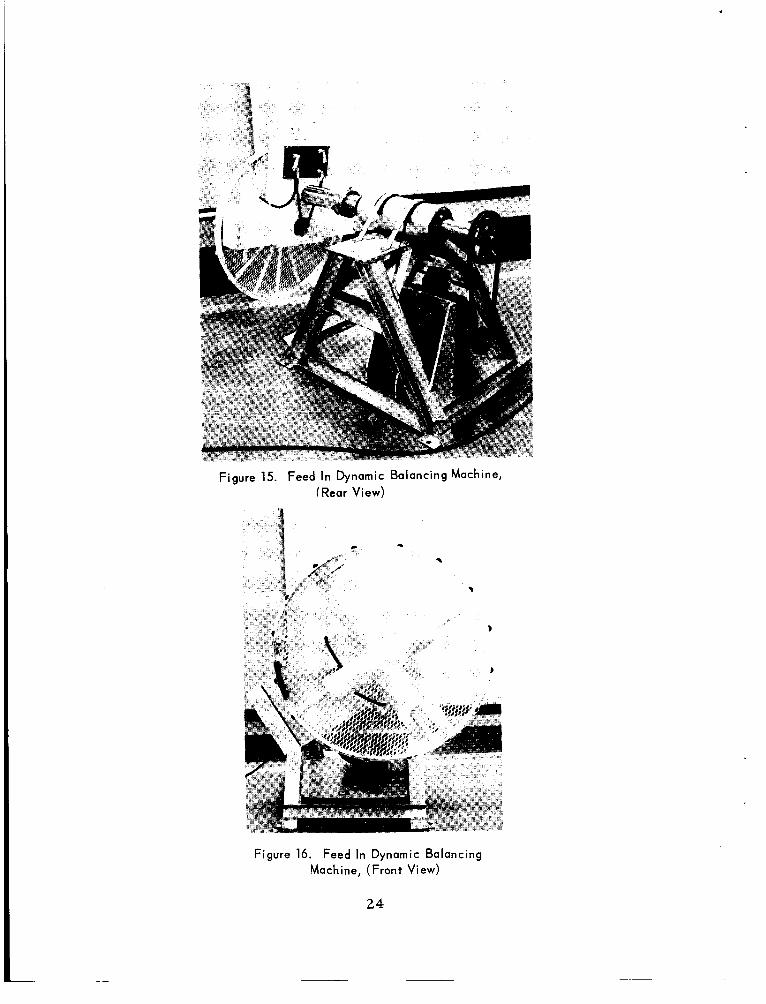
Figure 15. Feed In Dynamic Balancing Machine, (Rear View)
Figure 16. Feed In Dynamic Balancing Machine, (Front View)
24
.
I
I-
Y
0
I
LA W I U Z - I
t 2 4 W
V
n c" n Z 0
10 103 i o 4 VIBRATION FREQUENCY - CYCLES PER MINUTE
Figure 17. V i bration Severity Nomograph
25
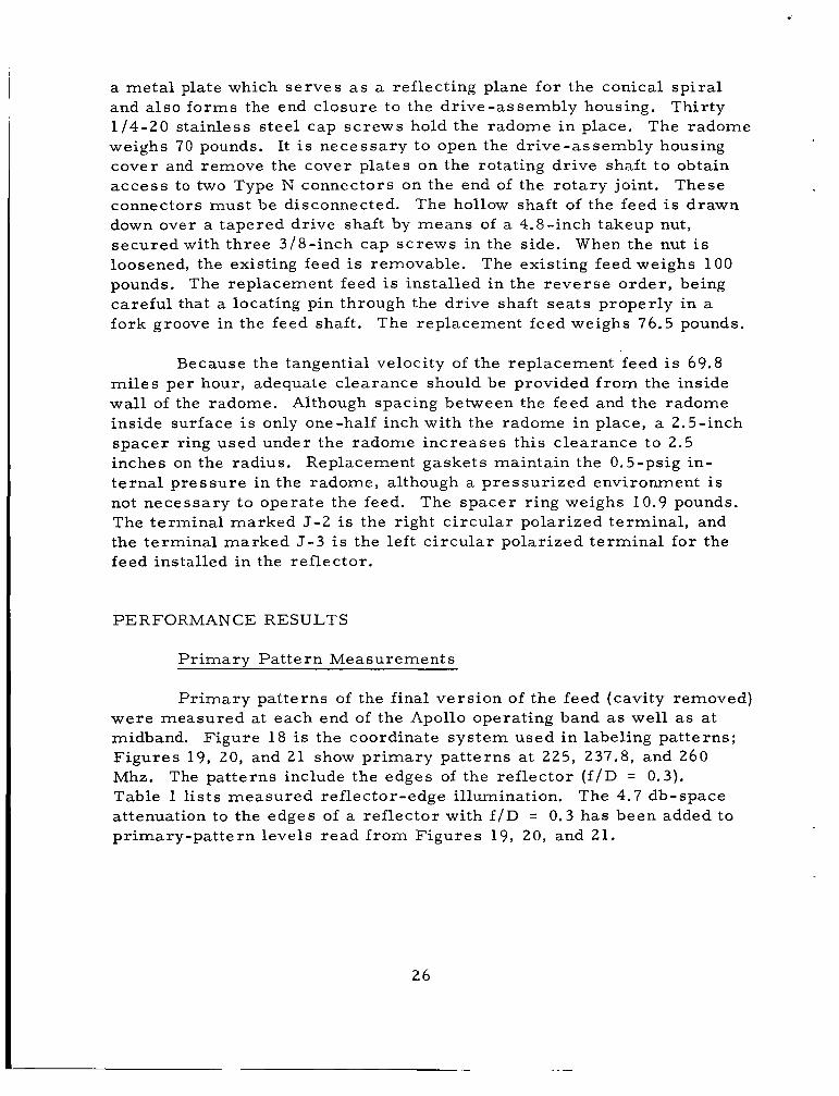
a meta l plate which se rves a s a reflecting plane for the conical sp i r a l and also forms the end closure to the dr ive-assembly housing. Thirty 1/4-20 stainless s teel cap screws hold the radome i n place. The radome weighs 70 pounds. It i s necessary to open the dr ive-assembly housing cover and remove the cover plates on the rotating drive shaft to obtain access to two Type N connectors on the end of the ro ta ry joint. These connectors must be disconnected. down over a tapered drive shaft by means of a 4.8-inch takeup nut, secured with three 3/8-inch cap screws in the side. loosened, the existing feed is removable. pounds. The replacement feed is installed in the r eve r se o rde r , being careful that a locating pin through the dr ive shaft sea ts properly in a fork groove in the feed shaft.
The hollow shaft of the feed i s drawn
When the nut i s The existing feed weighs 100
The replacement feed weighs 76.5 pounds.
Because the tangential velocity of the replacement feed i s 69.8 mi les per hour, adequate clearance should be provided f rom the inside wall of the radome. Although spacing between the feed and the radome inside surface i s only one-half inch with the radome in place, a 2.5-inch spacer ring used under the radome increases this c learance to 2.5 inches on the radius. t e rna l pressure in the radome, although a pressur ized environment i s not necessary to operate the feed. The terminal marked J - 2 i s the right c i rcu lar polarized terminal , and the terminal marked J - 3 is the lef t c i rcu lar polarized terminal for the feed installed in the reflector.
Replacement gaskets maintain the 0.5-psig in-
The spacer ring weighs 10.9 pounds.
PERFORMANCE RESULTS
Pr imary Pa t te rn Measurements
P r imary patterns of the final vers ion of the feed (cavity removed)
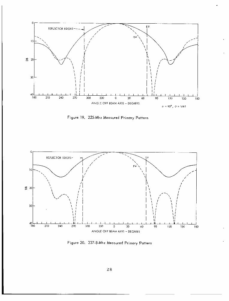
Figure 18 is the coordinate sys tem used i n labeling pat terns; were measured at each end of the Apollo operating band as well as a t midband. F igures 19, 20, and 21 show pr imary patterns a t 225, 237.8, and 260 Mhz. Table 1 l i s t s measured reflector-edge illumination. attenuation to the edges of a reflector with f / D = 0.3 has been added to pr imary-pat tern levels r ead f rom Figures 19, 20, and 21.
The patterns include the edges of the reflector ( f / D = 0.3). The 4.7 db-space
26

e =o"
Figure 18. Coordinate System For Primary Patterns
Table 1
R e f l e c to r E d g e I11 umina t ion
225 225 2 3 7 . 8 237.8 2 6 0 2 6 0
Plane Edge Illumination
23.5 db 11.2
7.7 20.7 10.2 19.3
27
.
0
10
g 2c
30
4c 1
ANGLE OFF BEAM AXIS - GEGREES 0 = 90°, 6 = VAR
Figure 19. 225-Mhz Measured Primary Pattern
\ I \ I
I I I I I I I I I I I I l l I I I I I l l I I [ I I I I I I U I I I 1
210 240 270 300 330 0 30 60 90 120 150 180
ANGLE OFF BEAM AXIS - DEGREES
Figure 20. 237-8-Mhz Measured Primary Pattern
2 8
.
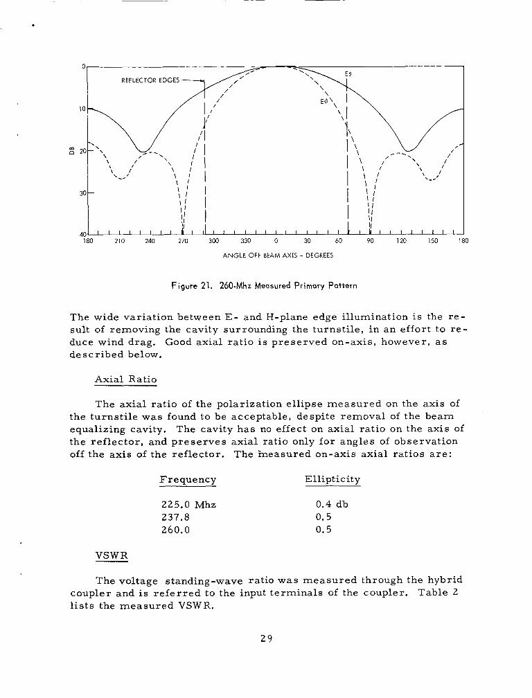
180 210 240 270 300 330 0 30 60 90 120 150 180
ANGLE OFF BEAM AXIS - DEGREES
Figure 21. 260-Mhz Measured Primary Pattern
The wide variation between E - and H-plane edge illumination is the r e - sult of removing the cavity surrounding the turnsti le, in an effort to r e - duce wind drag. de scr ibed below.
Good axial ratio i s p reserved on-axis, however, a s
Axial Ratio
The axial ratio of the polarization ell ipse measured on the axis of the turnst i le was found to be acceptable, despite removal of the beam equalizing cavity. the ref lector , and preserves axial ratio only for angles of observation off the axis of the reflector.
The cavity has no effect on axial ratio on the axis of
The measured on-axis axial ra t ios a r e :
Frequency Ellipticity
225.0 Mhz 0.4 db 237.8 0.5 260.0 0.5
VSWR
The voltage standing-wave ratio was measured through the hybrid coupler and i s r e fe r r ed to the input terminals of the coupler. l i s t s the measured VSWR.
Table 2
29
Table 2
Measured VSWR
Insertion Loss VSWR L C P (J3)
Frequency R C P ( J 2 )
225 MHz 1.08 1.13 0.08 237.8 1.20 1.09 0.05 260 1.05 1.08 0.05
-
Isolation
The isolation between on-axis lef t -c i rcular and r ight-circular in- coming signals can be calculated by knowing the measured axial ratio. This relationship i s
I = 20 log [E - :I (17)
where I i s the isolation in db and A i s the measured axial ratio. l i s t of on-axis axial ratios, shows the maximum to be 0.5 db, which co r - responds to a voltage ratio of 1.059.
The
Substituting in Expression (17)
r -+ 1.059 -t 1
I = 2o log 11.059 - 11
(19) I = 20 log 34.90
I = 30.9 db.
This isolation level is considerably bet ter than that necessary to a s s u r e good tracking.
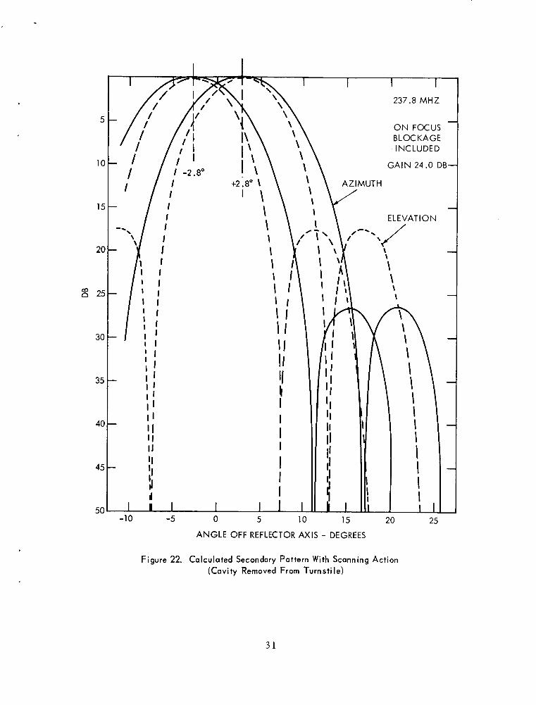
Predicted Secondary Pa t te rn
Figure 22 is the secondary pat tern of the final vers ion of the feed shown in Figure 14 with cavity removed, and was computed f o r the Apollo
30
5
10
15
20
25
30
35
40
45
50
237.8 MHZ
- ON FOCUS BLOCKAGE INCLUDED
GAIN 24.0 DB-
-
'I II
I
I I I1 I
I I I
I I I I 1 I I -10 -5 0 5 10 15
ANGLE OFF REFLECTOR AXIS - DEGREES
I I I I I I I 2
20 25
Figure 22. Calculated Secondary Pattern With Scanning Action (Cavity Removed From Turnsti le)
31
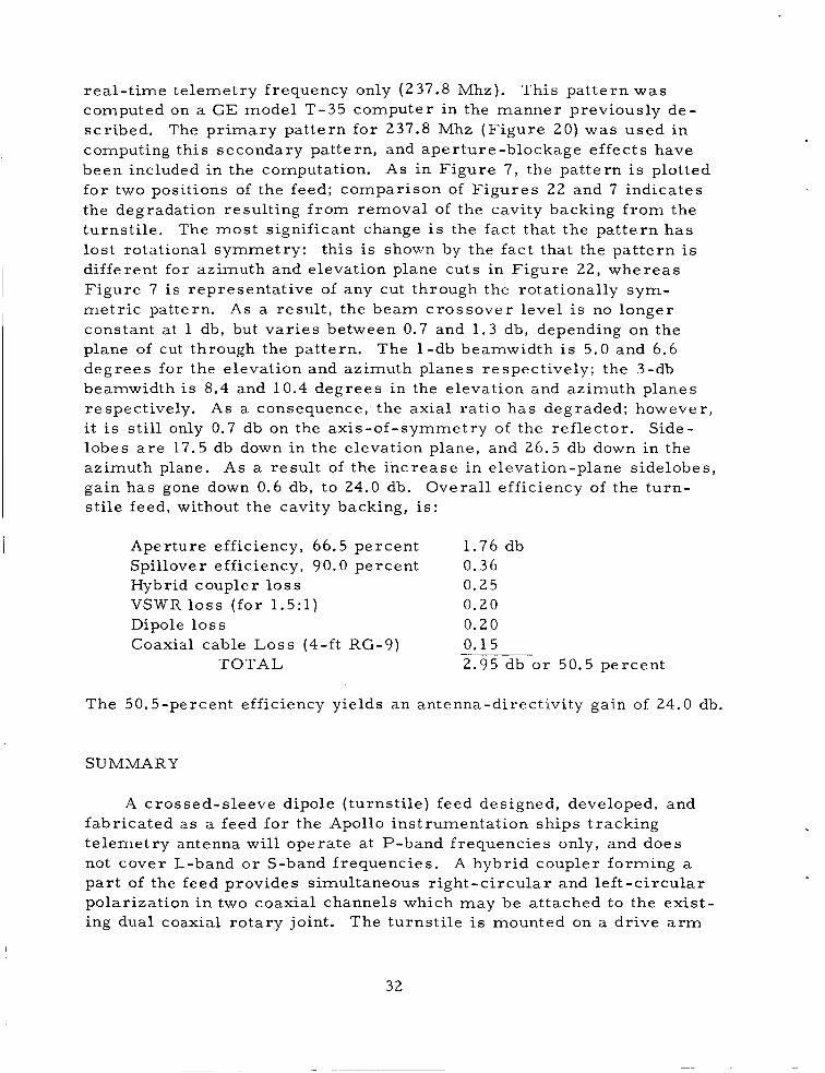
real- t ime te lemetry frequency only (237.8 Mhz). computed on a GE model T-35 computer in the manner previously de- sc r ibed , computing this secondary pattern, and aperture-blockage effects have been included in the computation. fo r two positions of the feed; comparison of F igures 22 and 7 indicates the degradation resulting f rom removal of the cavity backing f r o m the turnst i le . The mos t significant change is the fact that the pat tern h a s los t rotational symmetry: this is shown by the fac t that the pat tern is different for azimuth and elevation plane cuts in Figure 22, whereas Figure 7 i s representative of any cut through the rotationally sym- me t r i c pattern. As a resul t , the beam crossover level is no longer constant at 1 db, but v a r i e s between 0.7 and 1 .3 db, depending on the plane of cut through the pattern. The 1 -db beamwidth i s 5.0 and 6.6 degrees for the elevation and azimuth planes respect ively; the 3-db beamwidth is 8.4 and 10.4 degrees in the elevation and azimuth planes respectively. i t is s t i l l only 0.7 db on the axis-of-symmetry of the ref lector . Side- lobes a r e 17.5 db down in the elevation plane, and 26.5 db down in the azimuth plane. As a resu l t of the increase in elevation-plane sidelobes, gain has gone down 0.6 db, to 24.0 db. Overal l efficiency of the turn- s t i le feed, without the cavity backing, is:
This pat tern was
The pr imary pattern for 237.8 Mhz (F igure 20) was used in
AS in Figure 7 , the pat tern i s plotted
As a consequence, the axial ra t io has degraded; however,
Aperture efficiency, 66.5 percent Spillover efficiency, 90.0 percent 0.36 Hybrid coupler l o s s 0.25
1.76 db
VSWR l o s s ( for 1 .5: l ) 0.20 Dipole l o s s 0.20 Coaxial cable Loss (4-ft RG-9) 0.15
2.95 db o r 50.5 percent TOTAL
The 50.5-percent efficiency yields a n antenna-directivity gain of 24.0 db.
SUMMARY
A crossed-sleeve dipole ( turnst i le) feed designed, developed, and fabricated a s a feed fo r the Apollo instrumentation ships tracking te lemetry antenna will operate a t P-band frequencies only, and does not cover L-band o r S-band frequencies. pa r t of the feed provides simultaneous r ight-circular and le f t -c i rcu lar polarization in two coaxial channels which may be attached to the ex is t - ing dual coaxial rotary joint. The turns t i le is mounted on a dr ive arm
A hybrid coupler forming a
32
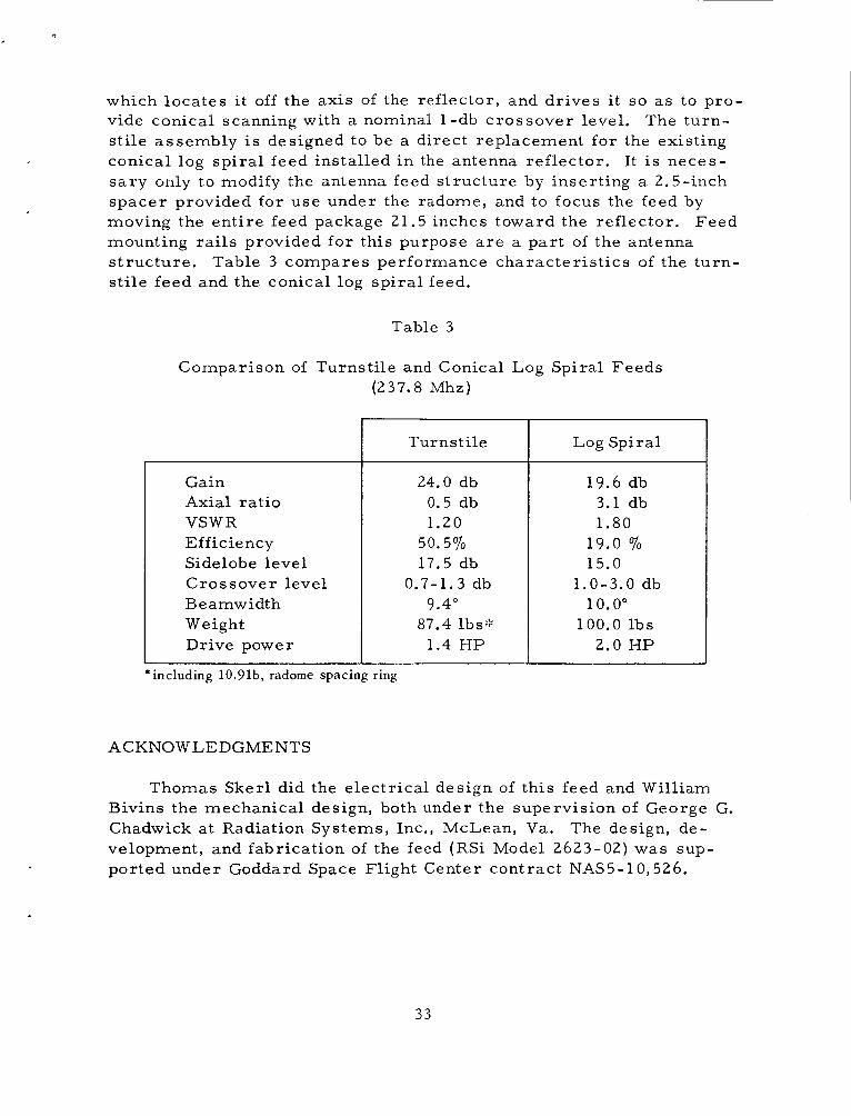
which locates i t off the axis of the reflector, and dr ives it so as to pro- vide conical scanning with a nominal 1-db crossover level. The turn- st i le assembly i s designed to be a direct replacement for the existing conical log sp i ra l feed installed in the antenna refiector. It i s neces- s a ry only to modify the antenna feed s t ructure by inserting a 2.5-inch spacer provided for use under the radome, and to focus the feed by moving the ent i re feed package 21.5 inches toward the reflector. mounting ra i l s provided f o r this purpose a r e a par t of the antenna s t ructure . st i le feed and the conical log sp i ra l feed.
Feed
Table 3 compares performance character is t ics of the turn-
Table 3
Comparison of Turnstile and Conical Log Spiral Feeds (237.8 Mhz)
Turnstile
Gain Axial ratio VSWR Efficiency Sidelobe level Crossover level Be amw idth Weight Drive power
*including 10.91b, radome spacing ring
ACKNOWLEDGMENTS
24.0 db 0.5 db 1.20
50.5% 17.5 db
0.7-1.3 db 9.4"
87.4 lbs::: 1.4 HP
Log Spiral
19.6 db 3.1 db 1.80
19.0 7'0 15.0
10.0" 1.0-3.0 db
100.0 lbs 2.0 HP
Thomas Skerl did the electrical design of this feed and William
The design, de- Bivins the mechanical design, both under the supervision of George G. Chadwick at Radiation Systems, Inc., McLean, Va. velopment, and fabrication of the feed (RSi Model 2623-02) was sup- ported under Goddard Space Flight Center contract NAS5-10,526.
3 3