a testbed for the msx attitude and tracking processors · computing power, and much greater...
TRANSCRIPT
A TESTBED FOR THE MSX ATTITUDE AND TRACKING PROCESSORS
A Testbed for the MSX Attitude and Tracking Processors
Daniel S. Wilson
he Midcourse Space Experiment (MSX) spacecraft employs infrared, ultraviolet,and visible light sensors to collect images and spectrographic signatures on a variety oftargets, especially missiles, other satellites, and auroral phenomena. These instrumentsare fixed in the satellite body and face in a common direction. Their fields of view vary,with some of them being quite small (1 3 3°). Thus, as MSX travels in its orbit, theentire satellite must be precisely rotated to keep the target in view. In fact, a pointingaccuracy requirement of 0.1° was imposed on the satellite’s design. To help meet thisrequirement, APL designed and built an elaborate testbed for the key elements of theMSX attitude and tracking subsystems. The testbed provides the means to assess theperformance of these subsystems through simulations of missile encounters and otherdata collection events.
T
INTRODUCTIONA robot and a satellite such as the Midcourse Space
Experiment (MSX) have much in common. The cur-rently accepted definition of a robot is a programmablemachine that, through the application of computertechnology, exhibits a high degree of flexibility oradaptability.1 That is, a robot, in the course of perform-ing its programmed function, can autonomously adaptits behavior (programmed motion) in response to cer-tain changes in its environment. Without the ability toadapt, the machine is merely a mechanical device.Thus, for a machine to be a robot it must be able to“perceive” (via sensor hardware), “think” (via comput-ers), and move (via actuators) without continuous
JOHNS HOPKINS APL TECHNICAL DIGEST, VOLUME 17, NUMBER 2 (19
human intervention. The MSX satellite, likewise, hasthe ability to sense its surroundings, determine a courseof action, and then autonomously perform the actionin the context of an assigned task.
The task assigned to MSX is the collection of sensordata on various targets. To maximize the scientific valueof the data, MSX must track the target and maintainit within 0.1° of the instruments’ common boresight.Today, such a pointing accuracy is routinely achievedby many astronomy satellites, but such satellites havean advantage over MSX: their “targets” (typically stars)are inertially fixed. Some of the MSX scenarios, incontrast, require the satellite to cartwheel to keep the
96) 161
D. S. WILSON
target missile in the field of view. For the MSX to satisfythe 0.1° pointing accuracy requirement while perform-ing such aerobatics is a considerable challenge forspacecraft designers. The attitude and tracking sub-systems of the MSX spacecraft are designed to meet thisrequirement. This article discusses how to test andvalidate these subsystems before their deployment intospace.
Designing a full-scale test environment in whichMSX could practice tracking intercontinental ballisticmissiles would require a large amount of space, a zero-gravity environment, and an enormous budget. Obvi-ously, what is needed instead is a testbed that can “fool”the spacecraft’s attitude and tracking elements into“thinking” that they are in orbit performing a realtarget-tracking scenario. This requirement was thecharter for the testbed. The testbed simulator was usedin all phases of testing, from unit level to end-to-endspacecraft level, to ensure that the system would meetits tracking specifications.
The concept of building a testbed to validate satel-lite-borne computers and software is not new. In fact,APL built testbed simulators for several earlier satellitesinvolved in tracking moving targets.2 The MSX testbedsimulator, however, is much more complex. It requiresmore sensor models, more environmental models, morecomputing power, and much greater fidelity than theearlier testbeds.
The role of the testbed simulator in the MSX projectmust be understood in the context of the satellite’sdesign. Therefore, a brief overview of the attitude andtracking subsystems of MSX is presented first in thisarticle followed by a discussion of the requirements forthe testbed simulator. The architecture and implemen-tation of the simulator are also explained, followed bya discussion of results and future uses of the testbed.
OVERVIEW OF MSX ATTITUDE ANDTRACKING SUBSYSTEMS
The Attitude SubsystemThe MSX attitude subsystem consists of a suite of
attitude sensors, four reaction wheels, three magnetictorquing rods, and the attitude processor (AP)—a 16-bit computer programmed in the Ada language to per-form autonomous, onboard attitude determination andcontrol. The attitude sensor suite consists of a digitalSun sensor, two Earth horizon sensors, a three-axismagnetometer, two ring laser gyroscopes, and a starcamera. The AP performs attitude control via the re-action wheels by independently commanding thetorque to be applied by each of four wheel motors. Thewheels may be spun in either direction at speeds up to
162 JOH
4500 rpm. By trading angular momentum between thesatellite body and the wheels, the spacecraft can beturned in any direction. The magnetic torquing rods areused to dump excess angular momentum from thewheels. By energizing one or more of these mutuallyorthogonal rods at the appropriate point in the orbit,the AP sets up an interaction of the magnetic fieldscreated by the rods with that of the Earth. The resultis a torque on the satellite that can be used to hold thesatellite stationary while the reaction wheels are slowlydecelerated.
The AP is the “brain” of the attitude subsystem. Itssoftware uses the measurements provided by the atti-tude sensors to determine the current orientation, i.e.,attitude, of the satellite axes relative to a standardinertial frame of reference. The AP software then cal-culates the necessary control signals to the reactionwheels to adjust the satellite to the desired attitude.This attitude is calculated in one of several ways, de-pending on the mode commands from the satelliteoperators on the ground. There are two primary attitudemodes. The first is the park mode, where the telescopesare pointed away from the Sun and Earth, while keep-ing the unblanketed side of the satellite rolled awayfrom the Sun. The other is the track mode, where thesatellite is pointed at the attitude requested by thetracking processor (TP).
The AP has some secondary functions as well. TheMSX satellite is equipped with two solar panels thatrotate about a common axis, and an X-band downlinkantenna mounted on a gimballed arm. The AP flightsoftware is responsible for keeping the solar panels ro-tated toward the Sun and the antenna pointed at theground station during passes over APL’s MSX TrackingStation.
The Tracking SubsystemThe MSX tracking subsystem consists mainly of the
S-band beacon receiver, portions of the Ultraviolet andVisible Imagers and Spectrographic Imagers (UVISI)instrument, and the TP—another 16-bit computer pro-grammed in Ada to perform autonomous, onboard tar-get tracking. During a data collection event, the APand TP engage in an electronic dialog using dedicatedelectrical interfaces to perform the desired spacecraftpointing. The AP provides the TP with the currentestimates of MSX’s orbit (position, velocity, and accel-eration) and attitude parameters (orientation, angularvelocity, and angular acceleration). The TP, in turn,provides the AP with the currently desired attitudeparameters. These data are exchanged twice per second.
Some of the targets to be tracked and imaged areequipped with radio beacons to maintain compliancewith the ABM treaty (1972), which prohibits unaided
NS HOPKINS APL TECHNICAL DIGEST, VOLUME 17, NUMBER 2 (1996)

acquisition and tracking of missiles from space. TheMSX spacecraft’s beacon receiver acquires such targetsat long range (up to 8000 km) and provides trackingsignals (azimuth and elevation angles and angle rates)to the TP.3
Some targets will be tracked with the aid of UVISI.Among the components of UVISI is an image proces-sor, which can analyze the output of any of the fourUVISI imagers and then provide the TP with thecoordinates in the imager’s frame of up to 23 detectedobjects (mostly stars).4 The TP uses motion analysisand a priori knowledge of the target to distinguish thedesired target from other objects.
The TP flight software provides the planners of adata collection event with a choice of eight pointingtypes. Commands are transmitted by ground operatorsto the TP giving it such information as the start andstop times of the data collection event, the pointingtype, characterization parameters, selected roll option,and selected scan pattern. For example, if the target isa two-stage missile, the set of characterization param-eters would include two sets of coefficients for thecurves that approximate the predicted flight path.These command parameters represent the “program-ming” of the “robot” for a given task.
Other supported pointing types include referenceobjects (small calibration spheres ejected from MSXitself), satellites, stars, auroral bright spots, Earth-boundobjects, Earth-limb pointing, and azimuth/elevationpointing in the local horizontal/local vertical referenceframe.5
The TP flight software combines the available sensormeasurements (from the beacon receiver or UVISI)with knowledge of the current MSX attitude (suppliedby the AP) and the a priori target estimates (from theuplinked commands) to produce, via a Kalman filter,refined estimates of the target trajectory. The TP soft-ware then calculates the new desired pointing state(attitude, angular velocity, and angular acceleration)and sends it to the AP. If the target missile’s pathdeviates from the a priori estimate because of a latelaunch or non-nominal booster performance, the TPsoftware adapts to the situation. Likewise, if a sensorblackout occurs, the TP flight software extrapolates thetarget state information to provide a continuous se-quence of desired attitude states to the AP.
A key consideration in the MSX attitude and track-ing subsystems is data latency. The MSX sensor plat-form is moving at more than 7 km/s and rotating atmore than 1.5°/s, and the target is moving at compa-rable speeds. Therefore, all sensor measurements mustbe time-tagged, and measurements and estimates mustbe propagated to a common time before they are incor-porated into the various tracking and steeringalgorithms.
JOHNS HOPKINS APL TECHNICAL DIGEST, VOLUME 17, NUMBER 2 (19
A TESTBED FOR THE MSX ATTITUDE AND TRACKING PROCESSORS
REQUIREMENTS FOR THE TESTBEDSIMULATOR
The primary requirement for the testbed simulatoris to provide a tool to support the development andcheckout of the flight software residing in the TP andAP. An analysis of the needs of the AP and TP flightsoftware development teams yielded the following sys-tem requirements:
1. Include hardware equivalent to the computer hard-ware in the actual TP and AP so that any differencesare transparent to the flight software. Thus, thetestbed simulator includes engineering models ofthe TP and AP. A testbed such as this is known as ahardware-in-the-loop simulator.
2. Connect directly to the flight computers (or theirfacsimiles) via the normal flight interfaces. Thetestbed simulator should present the same electricalinterfaces to the AP and TP as in the flight config-uration. This requirement is called first-circuit emulation.
3. Provide a configuration for testing the AP and theTP separately as well as simultaneously, and severalspecial configurations for testing larger strings ofsubsystems.
4. Model all other spacecraft subsystems relevant toboth the AP and the TP. These models are listed inthe first two sections of the boxed insert.
5. Model the space environment as it is perceived bythe spacecraft subsystems and the AP and TP. Thesemodels are listed in the last section of the boxedinsert. They are considered the testbed simulator’s“truth” models and “close the loop” between the AP/TP and the sensor models. For example, when theAP outputs a nonzero voltage on one of the reactionwheel torque interfaces, the spacecraft attitude dy-namics model calculates the resulting change inorientation and angular velocity. The attitude modelthen provides these inputs to the sensor models. Thesensor models generate new outputs to the AP,showing that the gyros registered the attitude mo-tion, the Sun moved in the Sun sensor’s field of view,the Earth moved in the horizon scanners’ fields ofview, etc.
6. Operate in real time. This requirement follows fromthe requirement to interface with the real flightsoftware while it is running in the flight computers.Although fast-forward and rewind features wouldhave been desirable, the flight software did notsupport these modes, so neither could the testbedsimulator.
7. Simulate various target types that were determinedby an analysis of mission science objectives (Table 1).
96) 163
D. S. WILSON
parallel, the set otestbed to emulatevarious satellite suchitecture would refor all the models real-time display, computers seamlesas well as expensiv
REQUIRED TE
Att
Command subsystData handling (teSun sensorEarth horizon senThree-axis magneThree-axis ring laStar cameraReaction wheels (Magnetic torquingSolar panel drivesX-band antenna gTracking processor
Tra
Command subsystData handling (teAttitude processorBeacon receiverUVISI image procOnboard Signal
associated with (SPIRIT III)
Space-Based Visib
Sun positionMoon positionStar positions andEarth’s magnetic fMSX spacecraft oMSX spacecraft atTargets
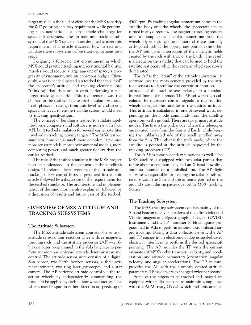
8. Provide the capability to record in disk log files allinputs and outputs of the systems under test (AP,TP, or both). These files are necessary to supportefficient debugging of the flight software. In addi-tion, the outputs of the truth models must be logged.Furthermore, the testbed simulator tool set mustinclude tools to examine and plot data from thesimulation log files.
9. Provide the ability to view the current log data whilethe simulation is in progress, since it is wasteful torun a 45-min simulation to completion if the testfailed in the first 10 min.This capability is alsoneeded for efficient debugging of flight software.
10. Provide the capability to drive stimulators for thespacecraft’s battery-charging electronics, the Sunsensor, the horizon scanners, the magnetometer, thebeacon receiver, and the UVISI imagers.
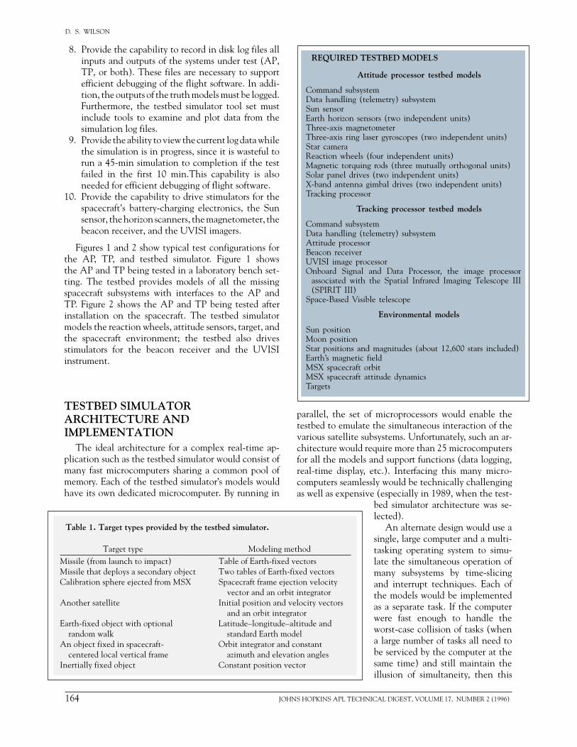
Figures 1 and 2 show typical test configurations forthe AP, TP, and testbed simulator. Figure 1 showsthe AP and TP being tested in a laboratory bench set-ting. The testbed provides models of all the missingspacecraft subsystems with interfaces to the AP andTP. Figure 2 shows the AP and TP being tested afterinstallation on the spacecraft. The testbed simulatormodels the reaction wheels, attitude sensors, target, andthe spacecraft environment; the testbed also drivesstimulators for the beacon receiver and the UVISIinstrument.
TESTBED SIMULATORARCHITECTURE ANDIMPLEMENTATION
The ideal architecture for a complex real-time ap-plication such as the testbed simulator would consist ofmany fast microcomputers sharing a common pool ofmemory. Each of the testbed simulator’s models wouldhave its own dedicated microcomputer. By running in
Table 1. Target types provided by the testbed simulator.
Target type Modeling methodMissile (from launch to impact) Table of Earth-fixed vectorsMissile that deploys a secondary object Two tables of Earth-fixed vectorsCalibration sphere ejected from MSX Spacecraft frame ejection velocity
vector and an orbit integratorAnother satellite Initial position and velocity vectors
and an orbit integratorEarth-fixed object with optional Latitude–longitude–altitude and
random walk standard Earth modelAn object fixed in spacecraft- Orbit integrator and constant
centered local vertical frame azimuth and elevation anglesInertially fixed object Constant position vector
164 JOH
f microprocessors would enable the the simultaneous interaction of thebsystems. Unfortunately, such an ar-quire more than 25 microcomputers
and support functions (data logging,etc.). Interfacing this many micro-sly would be technically challenginge (especially in 1989, when the test-bed simulator architecture was se-lected).
An alternate design would use asingle, large computer and a multi-tasking operating system to simu-late the simultaneous operation ofmany subsystems by time-slicingand interrupt techniques. Each ofthe models would be implementedas a separate task. If the computerwere fast enough to handle theworst-case collision of tasks (whena large number of tasks all need tobe serviced by the computer at thesame time) and still maintain theillusion of simultaneity, then this
STBED MODELS
itude processor testbed models
emlemetry) subsystem
sors (two independent units)tometerser gyroscopes (two independent units)
four independent units) rods (three mutually orthogonal units) (two independent units)imbal drives (two independent units)
cking processor testbed models
emlemetry) subsystem
essorand Data Processor, the image processorthe Spatial Infrared Imaging Telescope III
le telescope
Environmental models
magnitudes (about 12,600 stars included)ieldrbittitude dynamics
NS HOPKINS APL TECHNICAL DIGEST, VOLUME 17, NUMBER 2 (1996)
A TESTBED FOR THE MSX ATTITUDE AND TRACKING PROCESSORS
Figure 1 . Testbed simulator concept. The tracking processor (TP) and attitude processor (AP) are the spacecraft subsystems being tested.The testbed provides models of all the other spacecraft subsystems having interfaces to the TP and AP. Note the presence of the truth models:the Sun, Moon, magnetic field, orbit, attitude, and target models.
Trackingprocessor
Attitudeprocessor
Solar panelposition sensors
Reactionwheels
Space-BasedVisible
telescope
Truthmodels
SPIRIT III
Data handlingsubsystem
UVISI
OnboardSignal and
DataProcessor
Beaconreceiver
Solar paneldrives
Magnetictorque rods
Digital Sunaspect detector
Horizonscanners
Ring lasergyros
Magnetometer
Star camera
X-Band antennagimbal drive
assembly
Simulated Subsystems
Commandsubsystem
Subsystemsunder test
architecture would seem relatively risk-free because thecomputer hardware and multitasking operating systemcould be obtained as commercial, off-the-shelf (COTS)
A Motorola Cboard computer ter. This board in
Stimulator
Stimulator
Image library
Beaconreceiver
Testbedsimulator
Truth modeloutput to disk
Ideal imageand attitude
Radiofrequency
signals
Modifieddigitalimage
Object list (targetplus stars)
Target azimuthand elevation
angles
Estimatedattitude
Desiredattitude
Wheeltorques
Attitudesensordata
Target off-boresight angles
Actual attitude
UVISI Trackingprocessor
Attitudeprocessor
Figure 2 . Testbed simulator configuration for closed-loop spacecraft tests. The real spacecraftsubsystems replace the testbed’s models for the beacon receiver, UVISI, and command anddata handling (telemetry) subsystems.
JOHNS HOPKINS APL TECHNICAL DIGEST, VOLUME 17, NUMBER 2
equipment. However, with this ap-proach, the computer resourcescould be found deficient after thesimulator is implemented.
The architecture we chose forthe testbed simulator is a hybrid ofthe two extremes in the precedingdiscussion. That is, we procured afew microcomputers and a com-mercial multitasking operating sys-tem and linked them to a minicom-puter using COTS shared-memorytechnology.
The testbed simulator architec-ture is illustrated in Fig. 3. Theminicomputer used was a DigitalEquipment Corporation Micro-VAX 3800, running the VAX/VMS operating system. This com-puter is capable of about one mil-lion floating point operations persecond (1 mflops).orporation MVME 133A single-
was selected as the microcompu-cludes a 20-MHz Motorola 68020
(1996) 165
D. S. WILSON
the testbed simulatohardware architecturunit. Ada was the naguage given our spoand the nature of ourselected for most ofSeveral Ada compileopment systems for combination. In fact,industry standard amstrongly influenced omicrocomputer. We prehensive Ada Devpiler. With this tool VAX, which can beMotorola microcomp
Our software desimplemented as a taskputers in the VMEbof scenario creation, time display, report gassigned to the VAXnication was handledprotected buffers onVMS served as the the minicomputer, anReal Time Executivemicrocomputers.
We recognized eawould be used in a vonly, TP only, etc.). sign goal of being a
Systemundertest
Cableadapter
box
Timesync
Ethernet interfaceboard
1-MB globalmemory board
Analog and digitalinterface boards
Motorola 68020processor board
Motorola 68020processor board
Motorola 68020processor board
Motorola 68020processor board
MicroVAXcomputer
Operator displayterminals
Scenariofiles
Logfiles
VMEbus chassisSimulator Flighthardware
orengineering
model
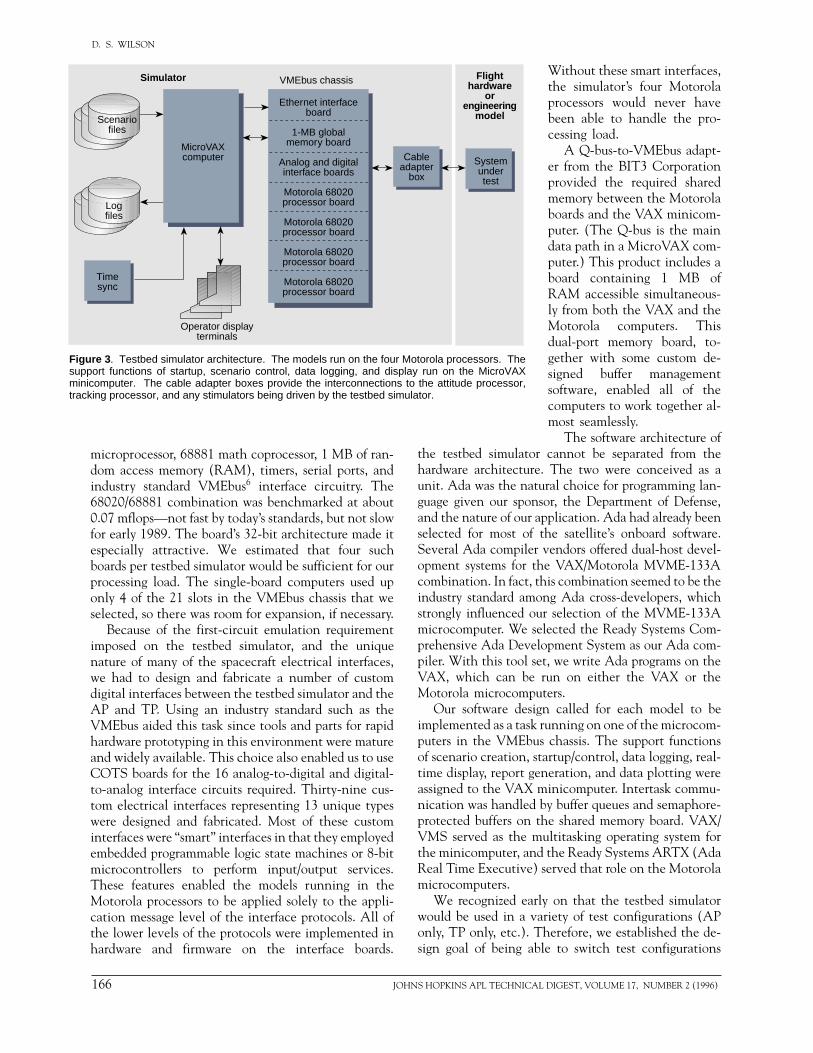
Figure 3 . Testbed simulator architecture. The models run on the four Motorola processors. Thesupport functions of startup, scenario control, data logging, and display run on the MicroVAXminicomputer. The cable adapter boxes provide the interconnections to the attitude processor,tracking processor, and any stimulators being driven by the testbed simulator.
microprocessor, 68881 math coprocessor, 1 MB of ran-dom access memory (RAM), timers, serial ports, andindustry standard VMEbus6 interface circuitry. The68020/68881 combination was benchmarked at about0.07 mflops—not fast by today’s standards, but not slowfor early 1989. The board’s 32-bit architecture made itespecially attractive. We estimated that four suchboards per testbed simulator would be sufficient for ourprocessing load. The single-board computers used uponly 4 of the 21 slots in the VMEbus chassis that weselected, so there was room for expansion, if necessary.
Because of the first-circuit emulation requirementimposed on the testbed simulator, and the uniquenature of many of the spacecraft electrical interfaces,we had to design and fabricate a number of customdigital interfaces between the testbed simulator and theAP and TP. Using an industry standard such as theVMEbus aided this task since tools and parts for rapidhardware prototyping in this environment were matureand widely available. This choice also enabled us to useCOTS boards for the 16 analog-to-digital and digital-to-analog interface circuits required. Thirty-nine cus-tom electrical interfaces representing 13 unique typeswere designed and fabricated. Most of these custominterfaces were “smart” interfaces in that they employedembedded programmable logic state machines or 8-bitmicrocontrollers to perform input/output services.These features enabled the models running in theMotorola processors to be applied solely to the appli-cation message level of the interface protocols. All ofthe lower levels of the protocols were implemented inhardware and firmware on the interface boards.
166 JOH
Without these smart interfaces,the simulator’s four Motorolaprocessors would never havebeen able to handle the pro-cessing load.
A Q-bus-to-VMEbus adapt-er from the BIT3 Corporationprovided the required sharedmemory between the Motorolaboards and the VAX minicom-puter. (The Q-bus is the maindata path in a MicroVAX com-puter.) This product includes aboard containing 1 MB ofRAM accessible simultaneous-ly from both the VAX and theMotorola computers. Thisdual-port memory board, to-gether with some custom de-signed buffer managementsoftware, enabled all of thecomputers to work together al-most seamlessly.
The software architecture ofr cannot be separated from thee. The two were conceived as atural choice for programming lan-nsor, the Department of Defense, application. Ada had already been the satellite’s onboard software.r vendors offered dual-host devel-the VAX/Motorola MVME-133A this combination seemed to be theong Ada cross-developers, whichur selection of the MVME-133A
selected the Ready Systems Com-elopment System as our Ada com-set, we write Ada programs on the run on either the VAX or theuters.
ign called for each model to be running on one of the microcom-
us chassis. The support functionsstartup/control, data logging, real-eneration, and data plotting were minicomputer. Intertask commu- by buffer queues and semaphore-
the shared memory board. VAX/multitasking operating system ford the Ready Systems ARTX (Ada
) served that role on the Motorola
rly on that the testbed simulatorariety of test configurations (AP
Therefore, we established the de-ble to switch test configurations
NS HOPKINS APL TECHNICAL DIGEST, VOLUME 17, NUMBER 2 (1996)
A TESTBED FOR THE
from the viewer)on the base of t
The Sun geomcorner) informs its orbit relative The line rotatesmaking it easy toan orbit away.
The reaction right corner) giveach of the four consumed by tonarrow white badisplay.
The boresighcorner) is the moing the pointingThe viewpoint isspacecraft, lookinspacecraft telescwhite circle (witThe green circle of radius 0.1°. Ifthan 1°, then theand the field of vof green. If the tthe boresight, thand the color swgood-fair-poor conumeric fields oand X-band ante
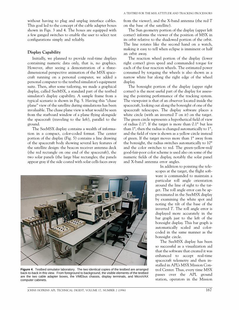
Figure 4 . Testbed simulator laboratory. The two identical copies of the testbed are arrangedback-to-back in this view. From foreground to background, the visible elements of the testbedare the two cable adapter boxes, the VMEbus chassis, display terminals, and MicroVAXcomputer cabinets.
without having to plug and unplug interface cables.This goal led to the concept of the cable adapter boxesshown in Figs. 3 and 4. The boxes are equipped witha few ganged switches to enable the user to select testconfigurations simply and reliably.
Display CapabilityInitially, we planned to provide real-time displays
containing numeric data only, that is, no graphics.However, after seeing a demonstration of a three-dimensional perspective animation of the MSX space-craft running on a personal computer, we added apersonal computer to the testbed simulator’s equipmentsuite. Then, after some tailoring, we made a graphicaldisplay, called SeeMSX, a standard part of the testbedsimulator’s display capability. A sample frame from atypical scenario is shown in Fig. 5. Having this “chaseplane” view of the satellite during simulations has beeninvaluable. The chase plane view is what would be seenfrom the starboard window of a plane flying alongsidethe spacecraft (traveling to the left), parallel to theground.
The SeeMSX display contains a wealth of informa-tion in a compact, color-coded format. The centerportion of the display (Fig. 5) contains a line drawingof the spacecraft body showing several key features ofthe satellite design: the beacon receiver antenna deck(the red rectangle on one end of the spacecraft), thetwo solar panels (the large blue rectangles; the panelsappear gray if the side coated with solar cells faces away
JOHNS HOPKINS APL TECHNICAL DIGEST, VOLUME 17, NUMBER 2 (
MSX ATTITUDE AND TRACKING PROCESSORS
, and the X-band antenna (the red The satellite).etry portion of the display (upper left
the viewer of the position of MSX into the shadowed portion of the orbit. like the second hand on a watch, tell when eclipse is imminent or half
wheel portion of the display (loweres speed and commanded torque for
reaction wheels. The estimated powerrquing the wheels is also shown as ar along the right edge of the wheel
t portion of the display (upper rightst useful part of the display for assess- performance of the tracking system. that of an observer located inside theg out along the boresight of one of the
opes. The display software places ah an inverted T on it) on the target.represents a hypothetical field of view the target is more than 0.1° but less radius is changed automatically to 1°,iew is shown as a yellow circle insteadarget moves more than 1° away frome radius switches automatically to 10°itches to red. The green-yellow-red/lor scheme is used also on some of thef the display, notably the solar panelnna error angles.
In addition to pointing the tele-scopes at the target, the flight soft-ware is commanded to maintain aparticular roll angle orientationaround the line of sight to the tar-get. The roll angle error can be ap-proximated in the SeeMSX displayby examining the white spot andnoting the tilt of the base of theinverted T. The roll angle error isdisplayed more accurately in thebar graph just to the left of theboresight display. This bar graph isautomatically scaled and color-coded in the same manner as theboresight circle.
The SeeMSX display has beenso successful as a visualization aidthat the software that created it wasenhanced to accept real-timespacecraft telemetry and then in-stalled in APL’s MSX Mission Con-trol Center. Thus, every time MSXpasses over the APL groundstation, operators in the Mission
1996) 167

D. S. WILSON
Figure 5 . Sample SeeMSX display showing MSX tracking a target almost perfectly. The spacecraft is pictured in the local vertical frame, and theEarth is directly below the spacecraft, which is traveling to the left (in the “ram” direction). The green circle shows the current azimuth (AZ) andelevation (EL) error angles relative to the target (the white circle).
Control Center will be able to assess the overall healthof the spacecraft attitude and tracking systems with aquick glance at the SeeMSX display.
Some Testbed ModelsDecisions had to be made regarding the level of
fidelity of the truth models. Standard satellite orbitmodels, for example, range from low-fidelity, computa-tionally simple models, to high-fidelity, computation-ally intensive models. The guiding principle in select-ing the proper level of fidelity was that the models hadto be just good enough to assess the performance of theflight software. For the orbit model, we chose to use theJ2 gravity model (Earth oblateness) with no distur-bance forces such as aerodynamic drag or solar radiationpressure. Over a few hours at an altitude of 900 km, draghas a negligible effect on MSX. The gravitational forcewas integrated via a fourth-order Runge–Kutta numer-ical integrator with a 0.5-s step size.
The spacecraft attitude truth model presented addi-tional choices. We chose to model the reaction wheeltorques, magnetic torque, gravity gradient torque, andthe torque due to the venting of cryogenic gas from theSPIRIT III telescope. Again, we chose to ignore aero-dynamic and solar pressure torques. The spacecraft at-titude dynamics are calculated by inserting the modeled
168 JOH
torques into Euler’s equation, as applied to a system withfour reaction wheels,7 solving for the vehicle accelera-tion, and then integrating over time. Because some ofthe attitude sensors (star camera and gyros) provideprecision attitude measurements to the AP at high rates(9 Hz for the star camera, 20 Hz for the gyros), we choseto use a 50-ms step size in the attitude model, togetherwith a second-order Runge–Kutta integrator.
The star camera model is among the most complexof the testbed simulator models. The MSX star cameraincludes an embedded processor that manages five in-dependent star-tracking windows that can be com-manded by the AP to acquire and then autonomouslytrack any five stars available in the camera’s field ofview. The camera sends a serial digital message ninetimes per second to the AP. This message contains thecurrent coordinates and magnitude (brightness) of thestars being tracked by the five windows. The AP em-ploys an onboard star catalog of about 9,200 stars andpattern-matching software to determine attitude fromthe star camera’s messages with an accuracy of a fewarcseconds. The onboard catalog was constructed fromstandard star catalogs by culling out faint stars in re-gions of high star density (i.e., in the galactic plane)and stars with near neighbors.
The testbed simulator model includes the softwarelogic necessary to emulate the camera’s functionality.
NS HOPKINS APL TECHNICAL DIGEST, VOLUME 17, NUMBER 2 (1996)
To realistically model the behavior of the camera, thesimulator employs a star catalog of about 12,600 stars.This catalog is complete down to stars of magnitude 6.4.Therefore, this catalog, unlike the artificially thinnedcatalog embedded by the AP, is representative of thenatural distribution of stars in the sky. The model thenadds Gaussian noise to the star measurements in a waythat increases with spacecraft slue rate. The model alsoemploys a variable brightness threshold that causes thecamera to drop track on fainter stars as the cameraboresight approaches bright objects such as the Sun,Moon, or Earth. To run at 9 Hz, the star camera modelrequired an entire Motorola processor board dedicatedto it.
Connections to Other StimulatorsThe testbed simulator was conceived primarily as a
test tool for the AP and TP. However, with its truthmodels, the testbed has the necessary information toalso drive stimulators for a variety of related subsystems.For example, throughout a simulation, the testbed sim-ulator “knows” where the spacecraft, Sun, and Earthare. It “knows” the current spacecraft attitude and therotation angles of the solar panels. With this informa-tion, the testbed simulator can calculate the amount ofenergy available from the solar panels. Thus, the test-bed simulator was designed to make this calculationand write a message once per second to a stimulatorattached to the spacecraft’s battery-charging electron-ics. Similar techniques were employed to make thetestbed simulator drive stimulators for the Sun sensor,horizon scanners, magnetometer, beacon receiver, andUVISI. These features allowed the testbed simulator toput major strings of spacecraft subsystems through re-alistic mission scenarios.
The testbed simulator’s ability to drive stimulatorsfor the beacon receiver and UVISI is noteworthy. In thecase of the beacon receiver, the testbed simulator usesits orbit, target, and attitude models to calculate thetarget’s azimuth and elevation angles relative to thecenter of the beacon receiver’s field of view. These dataare sent to a computer-controlled stimulator that putsthe corresponding phase shifts into the radio-frequencysignals being inserted into the beacon receiver’s anten-na leads. The beacon receiver’s electronics then “see”the target exactly where the testbed simulator says itis. The beacon receiver’s embedded computers thencalculate the target azimuth and elevation angles, andsend this information to the TP, which in turn tries todrive the azimuth and elevation angles to zero by gen-erating a new desired attitude for the AP. In response,the AP torques the reaction wheels to rotate the ve-hicle accordingly. Since the reaction wheels are beingemulated by the testbed simulator, we have a closed-loop, nearly end-to-end simulation of the MSX track-ing system.
JOHNS HOPKINS APL TECHNICAL DIGEST, VOLUME 17, NUMBER 2 (19
A TESTBED FOR THE MSX ATTITUDE AND TRACKING PROCESSORS
For the UVISI imagers, the details are more compli-cated, but the effect is the same. In a typical missile-tracking scenario, the imagers are expected to see acomplex scene containing star streaks, the Earth limb,and the rocket plume. If we assume that the MSX orbit,the target trajectory, and the tracking and attitudeperformance are perfectly nominal, then we can assumethat the target would be in the exact center of theimage. Using such logic, all of the digital images for aparticular scenario can be simulated in advance andsaved in a library.
But in any given simulation, the tracking and atti-tude performance are not perfect, resulting in the targetbeing somewhat off-center relative to the UVISI im-ager field of view. Since our goal is to assess trackingand attitude performance, we cannot assume that thetarget is in the center of each image. We solved thisproblem by generating the images slightly larger thanthe actual imager field of view. Then, during a simu-lation, the testbed simulator sends the current attitudeto a computer-controlled stimulator for UVISI. Thestimulator compares the current attitude with thenominal attitude used to generate the image for thecurrent time. If the difference is nil, then the stimulatorslices out the center portion of the oversized image andinjects it into the UVISI flight electronics, just as if itcame from the focal plane unit. However, if the attitudedifference indicates that the target is slightly off to theright, then the stimulator slices out a portion of theimage slightly to the left of center. Thus, this designpermits nearly end-to-end simulation of MSX trackingscenarios involving the UVISI imagers.
RESULTSThe testbed simulator began to be used by the AP
and TP flight software development teams at about themidpoint of their implementation phase. Prior to that,the flight software developers tested their softwareusing the custom test equipment suite used by the flighthardware development team. As the flight (and test-bed) software matured, the testbed simulator’s ability todrive realistic mission scenarios increasingly made itthe method of choice for testing. Hundreds of simula-tions were run during the latter half of the flight soft-ware implementation period. These runs typicallyemployed the testbed’s AP-only and TP-only modes.
Flight Software TestingMost of the flight software defects found with the
testbed simulator were, as expected, due to programmeror analyst error. Nevertheless, a handful of errors weretraced to defects in the Ada compiler being used by theflight software team. That is, the program contained acorrect sequence of statements in the Ada language, but
96) 169
D. S. WILSON
the compiler did not translate the statements into acorrect sequence of machine language statements. Suchproblems remind us that although the use of COTSproducts greatly reduces risk, risk cannot be eliminatedentirely.
As the AP and TP flight software neared comple-tion, the engineering models of the AP and TP flightcomputers were mated to one another on a laboratorybench and then tested as a unit with the testbed sim-ulator. Next, the prototype beacon receiver electronicswere added, along with their own testbed equipment.As described in the preceding section, the testbed sim-ulator was linked to the beacon receiver’s testbed equip-ment (i.e., stimulator) to allow testing of closed-loopmissile tracking. Then the prototype UVISI imageprocessor was added, along with its own testbed equip-ment, and more closed-loop missile tracking scenarioswere conducted.
After the flight hardware for the AP and TP wasintegrated with the spacecraft, one of the two copies ofthe testbed simulator was relocated to the integrationfacility, and simulations with flight hardware in theloop began. These tests included the following:
1. Spacecraft/booster separation and initial attitude ac-quisition, including detumbling from non-nominalseparation, deploying the solar panels, and orientingthe panels to the Sun
2. Initial X-band antenna deployment and the first fewstation passes
3. Reaction wheel momentum dumping using the grav-ity gradient torque and using the magnetic torque rods
4. AP response to attitude sensor failures5. Tracking of missiles, ejected reference objects, and
other satellites6. Earth-limb and celestial background scans7. Thermal/vacuum performance
Missile Tracking Scenarios
For the MSX tracking subsystems, the closed-loopmissile tracking scenarios were the most interesting andchallenging spacecraft tests. One such test, MSX Ded-icated Target (MDT) V, involved tracking a missilefrom horizon to horizon with both the beacon receiverand one of the UVISI imagers. The geometry of theencounter required the spacecraft’s pitch rates to reach1.3°/s at the point of closest approach between themissile and MSX. The high angular velocity stresses theAP’s attitude determination algorithm, its attitude con-trol algorithm, and the TP’s trajectory determinationalgorithm. Several variations of this scenario were run:
1. Beacon receiver tracking only2. UVISI imager tracking only3. Simultaneous beacon receiver and UVISI imager
tracking4. Late missile launch
170 JOHN
5. Intentional beacon receiver loss of track and reacqui-sition in the middle of the run
One of the more interesting issues that surfacedduring tests of the MDT V scenario was a problem withstars falling into the target tracking gate. Recall thatthe UVISI image processor sends a message to the TPeach 0.5 s containing a list of up to 23 objects detectedin its field of view. The target is presumably in the listsomewhere; the rest of the objects are probably stars.The TP uses its current estimate of the target positionand velocity, together with the current estimate ofattitude and angular velocity from the AP, to identifythe target among the list of objects. Objects in the listthat appear inertially fixed (but moving in the imagerframe) are probably stars; an object that appears to bemoving inertially (but fixed in the imager frame) isprobably the target. The TP draws a box, called a gate,around the portion of the imager frame where the targetis expected to be. The MDT V tests with the UVISIimagers revealed that in some image compaction modesof the imager, the TP’s target gate was too large, leadingto a high probability that a star would fall in the targetgate. The TP was observed to track the star for a fewseconds before returning to the real target. The analysisof this anomaly led to the alteration of the interfacebetween UVISI and the TP. The UVISI image proces-sor flight software was modified to include the compac-tion factor in its message to the TP. The TP flightsoftware was modified to dynamically change the sizeof the target gate based on the current UVISI imagecompaction factor. The result was improved targettracking performance with the UVISI imagers.
The high rotation rates demanded by the MDT Vscenario helped the team find other problems in theflight software, too. For example, we found that theattitude determination algorithms, which performedsuperbly at modest rates, broke down badly at highrates. One of the testbed simulator’s analysis tools gen-erated a report and graphs showing the difference be-tween the AP’s attitude estimate, as reported in thetelemetry stream, and the testbed’s attitude truth mod-el. This tool highlighted the rate dependence in theAP’s attitude error. By experimenting on the testbedwith various simulated attitude sensor failures, we wereable to show that the errors were in the AP’s processingof gyro data. After the flight algorithms were modifiedto correctly compensate for the latency in the gyro data,the testbed’s analysis tool showed that the performanceof the AP’s attitude determination software was accept-able even at rates higher than those in the MDT Vscenario.
Figure 6 presents testbed simulator data from one ofthe MDT V scenarios. In this variant, the TP’s closed-loop tracking algorithm employed data from both thebeacon receiver and the narrow-field visible light
S HOPKINS APL TECHNICAL DIGEST, VOLUME 17, NUMBER 2 (1996)
1500 1700 1900 2100 2300 2500 2700
0.01
0.02
0.03
0
–0.01
0
0.02
–0.02
–0.04
–0.06
–0.08
Simulated elapsed time (s)
Targ
et a
ngle
z (
deg)
Targ
et a
ngle
y (
deg)
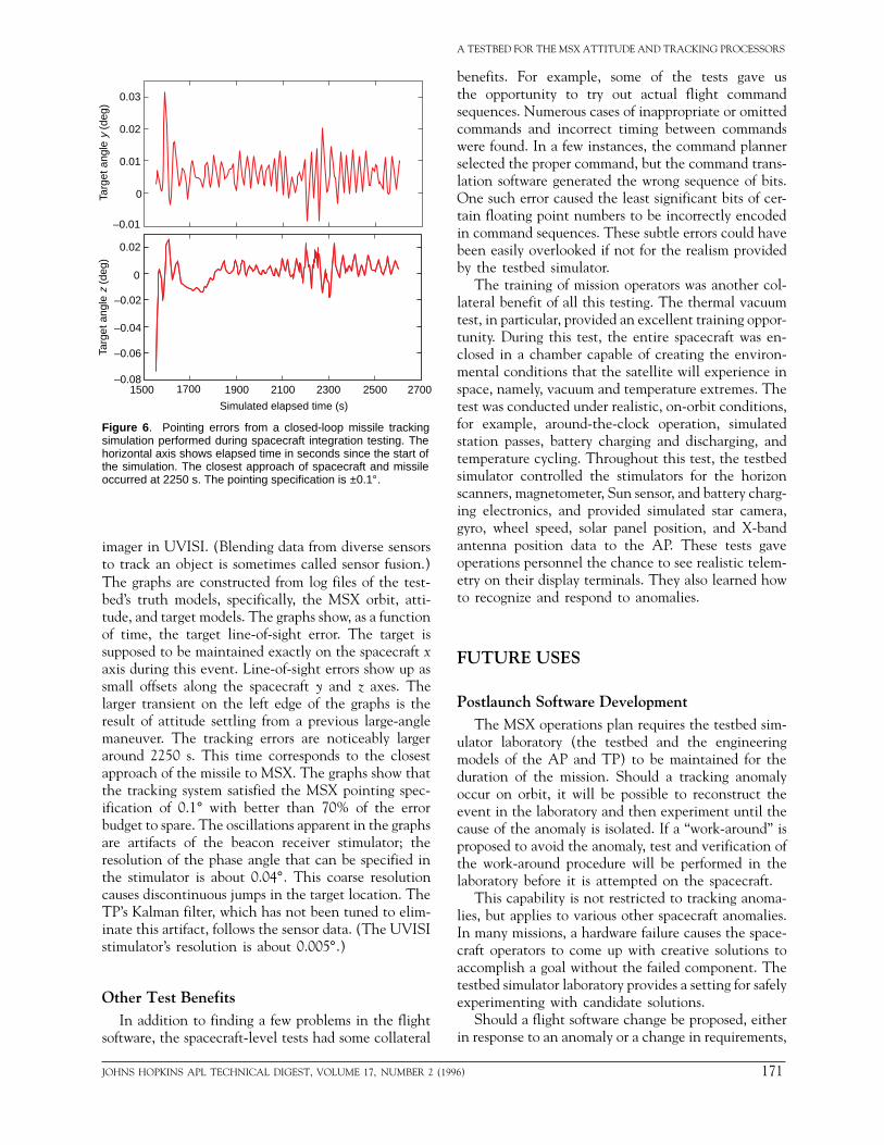
Figure 6 . Pointing errors from a closed-loop missile trackingsimulation performed during spacecraft integration testing. Thehorizontal axis shows elapsed time in seconds since the start ofthe simulation. The closest approach of spacecraft and missileoccurred at 2250 s. The pointing specification is ±0.1°.
imager in UVISI. (Blending data from diverse sensorsto track an object is sometimes called sensor fusion.)The graphs are constructed from log files of the test-bed’s truth models, specifically, the MSX orbit, atti-tude, and target models. The graphs show, as a functionof time, the target line-of-sight error. The target issupposed to be maintained exactly on the spacecraft xaxis during this event. Line-of-sight errors show up assmall offsets along the spacecraft y and z axes. Thelarger transient on the left edge of the graphs is theresult of attitude settling from a previous large-anglemaneuver. The tracking errors are noticeably largeraround 2250 s. This time corresponds to the closestapproach of the missile to MSX. The graphs show thatthe tracking system satisfied the MSX pointing spec-ification of 0.1° with better than 70% of the errorbudget to spare. The oscillations apparent in the graphsare artifacts of the beacon receiver stimulator; theresolution of the phase angle that can be specified inthe stimulator is about 0.04°. This coarse resolutioncauses discontinuous jumps in the target location. TheTP’s Kalman filter, which has not been tuned to elim-inate this artifact, follows the sensor data. (The UVISIstimulator’s resolution is about 0.005°.)
Other Test BenefitsIn addition to finding a few problems in the flight
software, the spacecraft-level tests had some collateral
JOHNS HOPKINS APL TECHNICAL DIGEST, VOLUME 17, NUMBER 2 (1
A TESTBED FOR THE MSX ATTITUDE AND TRACKING PROCESSORS
benefits. For example, some of the tests gave usthe opportunity to try out actual flight commandsequences. Numerous cases of inappropriate or omittedcommands and incorrect timing between commandswere found. In a few instances, the command plannerselected the proper command, but the command trans-lation software generated the wrong sequence of bits.One such error caused the least significant bits of cer-tain floating point numbers to be incorrectly encodedin command sequences. These subtle errors could havebeen easily overlooked if not for the realism providedby the testbed simulator.
The training of mission operators was another col-lateral benefit of all this testing. The thermal vacuumtest, in particular, provided an excellent training oppor-tunity. During this test, the entire spacecraft was en-closed in a chamber capable of creating the environ-mental conditions that the satellite will experience inspace, namely, vacuum and temperature extremes. Thetest was conducted under realistic, on-orbit conditions,for example, around-the-clock operation, simulatedstation passes, battery charging and discharging, andtemperature cycling. Throughout this test, the testbedsimulator controlled the stimulators for the horizonscanners, magnetometer, Sun sensor, and battery charg-ing electronics, and provided simulated star camera,gyro, wheel speed, solar panel position, and X-bandantenna position data to the AP. These tests gaveoperations personnel the chance to see realistic telem-etry on their display terminals. They also learned howto recognize and respond to anomalies.
FUTURE USES
Postlaunch Software DevelopmentThe MSX operations plan requires the testbed sim-
ulator laboratory (the testbed and the engineeringmodels of the AP and TP) to be maintained for theduration of the mission. Should a tracking anomalyoccur on orbit, it will be possible to reconstruct theevent in the laboratory and then experiment until thecause of the anomaly is isolated. If a “work-around” isproposed to avoid the anomaly, test and verification ofthe work-around procedure will be performed in thelaboratory before it is attempted on the spacecraft.
This capability is not restricted to tracking anoma-lies, but applies to various other spacecraft anomalies.In many missions, a hardware failure causes the space-craft operators to come up with creative solutions toaccomplish a goal without the failed component. Thetestbed simulator laboratory provides a setting for safelyexperimenting with candidate solutions.
Should a flight software change be proposed, eitherin response to an anomaly or a change in requirements,
996) 171
D. S. WILSON
the software developers will use the testbed simulatorto test and validate the changed software, and then runan extensive set of regression tests to ensure that thechange has not inadvertently introduced an error else-where in the software. This is the same regression testsuite that we already used to validate the final pre-launch flight software programs.
Event RehearsalsIn addition to its use in support of flight software
maintenance, the testbed simulator has an evolvingrole in support of operations planners. The analyststasked with the translation of experimenters’ requestsinto a scheduled data collection event on the spacecrafthave a variety of tools that they routinely use duringthe planning process. The development of software toconvert their planned sequences of spacecraft com-mands into the format required for testbed simulatorscenarios makes it possible to rehearse the plannedevent on the testbed. Although such rehearsals are notpractical for every event due to the real-time nature ofthe testbed simulator (What value is a 24-hour weatherforecast if it takes 24 hours to generate it?), it is usefulto have this capability for use with certain high-valueor particularly complicated events. Operations plannersmade extensive use of this rehearsal capability duringprelaunch event planning.
CONCLUSIONThe investment made in developing the testbed sim-
ulator has helped to ensure that the MSX will meet its
172 JOH
tracking specifications. This investment will continueto pay dividends throughout the mission life as thetestbed simulator supports anomaly investigation, flightsoftware maintenance, and event planning.
REFERENCES1Clarke, R., “Asimov’s Laws of Robotics: Implications for InformationTechnology,” Comput. 26(12), 53–61 (1993).
2Englar, T. S., Gregorski, F. S., Smith, R. R., Frank, W. A., and Wilson, D.S., “Simulation of the Environment of an Autonomous Satellite to Providea Testbed for Real-Time Software/Hardware Validation,” in Proc. 1989Summer Comput. Simul. Conf., Austin, TX, pp. 247–253 (1989).
3Valverde, C. R., Stilwell, R. K., Russo, A. A., and McKnight, T. R., “The S-Band Beacon Receiver for the Midcourse Space Experiment,” Johns HopkinsAPL Tech. Dig. 15(1), 67–81 (1994).
4Murphy, P. K., Waddell, R. L., and Heyler, G. A., “Image and TrackProcessing in Space (Part II),” in Proc. AIAA Comput. Aerosp. 9 Conf., SanDiego, CA, pp. 586–596 (1993).
5Waddell, R. L., Murphy, P. K., and Heyler, G. A., “Image and TrackProcessing in Space (Part I),” in Proc. AIAA Comput. Aerosp. 9 Conf., SanDiego, CA, pp. 576–585 (1993).
6The VMEbus Specification, VMEbus International Trade Association,Scottsdale, AZ (1987).
7Vadali, S. R., and Junkins, J. L., “Optimal Open-Loop and Stable FeedbackControl of Rigid Spacecraft Attitude Maneuvers,” J. Astronaut. Sci. 32(2),105–122 (1984).
ACKNOWLEDGMENTS: The testbed simulator was the result of the work ofmany people. The author would like to express his appreciation to L. Lee Pryor fortechnical and managerial assistance; Warren A. Frank for architectural contribu-tions; Thomas W. LeFevere for architectural, electrical, and software engineeringcontributions; Barry N. Brown, John Rodell, and Kenneth E. Williams for analyti-cal support; and Lydia A. Baker, Hugh C. Davey, Michael G. Mohler, and MichaelL. Schaeffer for software engineering support. The MSX mission is sponsored by theBallistic Missile Defense Organization. This work was supported under contractN00039-94-C-0001.
THE AUTHOR
DANIEL S. WILSON is a member of the Senior Professional Staff in APL’sSpace Department. He received a B.A. degree in mathematics in 1974 fromFranklin and Marshall College in Pennsylvania. Mr. Wilson has worked onground systems in support of numerous NASA and DoD satellites, including theHubble Space Telescope and the Strategic Defense Initiative’s Delta 181 andDelta 183 satellites. His work has been chiefly in the areas of spacecraft attitudedetermination and control. Mr. Wilson is currently working on a planningsimulator to be used in support of NASA’s Near Earth Asteroid Rendezvous. Hise-mail address is [email protected].
NS HOPKINS APL TECHNICAL DIGEST, VOLUME 17, NUMBER 2 (1996)