a temporal logic for multilevel reasoning about hardware
TRANSCRIPT
A Temporal Logic for Multilevel
Reasoning about Hardware
Ben MoszkowskiComputer Laboratory, Cambridge University, England
Because digital systemsoperate over time,
hardware descriptionsshould be based onformalisms suited to
temporal reasoning. Onesuch notation, intervaltemporal logic, offers anatural basis for the
specification of devicesand digital signals.
As computer systems continue togrow in complexity, the distinc-
tion between hardware and software isbecoming increasingly blurred. Thissituation has produced an increasingawareness of the need for behavioralmodels suited to specifying and rea-soning about both digital devices andprograms. Contemporary hardwaredescription languages (for example,Barbacci, Parker and Wallace,2 andSu et al. 3) are not sufficient because ofvarious limitations:
* Most such tools are intended morefor simulation than for mathema-tically sound reasoning aboutdigital systems. Compromisesmust be made so that the descrip-tions can be executed directly.
* Difficulties arise in developing cir-cuit specifications that of neces-sity must refer to different levelsof behavioral abstraction.
* What formal tools there are forsuch languages generally cannotdeal with the inherent parallelismand nondeterminism of circuits.
The approach presented here offersone way to overcome these problemsand unifies, in a single notation, digitalcircuit behavior that is generally de-scribed by means of the followingtechniques: register transfer opera-tions, flowgraphs and transition ta-bles, tables of functions, timingdiagrams, and schematics and blockdiagrams.Temporal logic contains various
useful operators for looking at periods
of time. Some of these constructs aresimilar to certain kinds of statementsfound in Algol and related program-ming languages. We will use intervaltemporal logic, a generalization of thesyntax and semantics of standard tem-poral logics,45 to reason about discretetime intervals. ITL includes conven-tional logical constructs such as "pand q" and "p implies q," as well astime-dependent ones such as "alwaysp" and "p followed by q. "
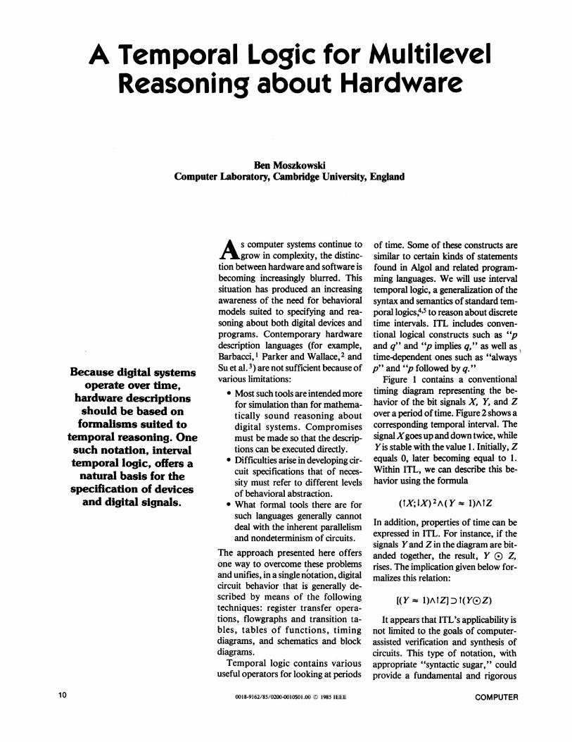
Figure 1 contains a conventionaltiming diagram representing the be-havior of the bit signals X, Y, and Zover a period of time. Figure 2 shows acorresponding temporal interval. Thesignal Xgoes up and down twice, whileYis stable with the value 1. Initially, Zequals 0, later becoming equal to 1.Within ITL, we can describe this be-havior using the formula
(tX;. IX) 2A ( Y -- I)AItZ
In addition, properties of time can beexpressed in ITL. For instance, if thesignals Yand Z in the diagram are bit-anded together, the result, Y i Z,rises. The implication given below for-malizes this relation:
[(Y -- I)AtZ] D t(Y()Z)
It appears that ITL's applicability isnot limited to the goals of computer-assisted verification and synthesis ofcircuits. This type of notation, withappropriate "syntactic sugar," couldprovide a fundamental and rigorous
0018-9162/85/0200-0010$01.00 © 1985 IEEE10 COMPUTER

basis for communicating, reasoning,or teaching about digital concepts anddevices. Simulation-based languagescould, for example, use such a logic asa vehicle for describing the intendedsemantics of delays and other features.Moszkowski6 discusses how ITL canserve as the basis for a programminglanguage called Tempura. Thus, semi-automated correctness checking isreally only one part of a much biggerpicture.
Related work
Gordon's denotational semantics.Gordon's work7 on register-transfersystems uses denotational semantics toprovide a concise means for reasoningabout clocking, feedback, instruction-set implementation, and bus commu-nication. For example, a simple multi-plexer can be specified as
Mux = X[switch,inl,in2,out}.[out = (switch-inl,in2)jMux
This example uses a form of lambdaexpression to state that the device hasfour pins. The pin out always equalseither in I or in2 depending on thevalue of switch.A register is specified as
Reg(n) = X[in,out.[out = n];Reg(in).
In essence, the register has an outputout that always equals the state n. Theregister's next state is always the cur-rent value of the input in.
Using Gordon's notation, it is possi-ble to combine devices and prove thatthe resulting systems operate correctly.This approach has been used to specifyand verify an nmos stack cell, amultiplier, and a microprogrammedcomputer.
Wagner's proof checker. Wagner8implements a proof checker for rea-soning about signal transitions andregister transfer behavior. For exam-ple, the formula
tx a I -X
is interpreted as stating that the bitsignalX rises exactly if its complement-X falls. Such properties of signalsare taken as axioms. The formula
/CountA tClock/X- -'X
represents a situation in which when-ever the signal Count is high and thesignal Clock rises, the value of X iscomplemented. Within Wagner's sys-tem, properties such as the followingequivalence can be obtained:
(/CountA tClock/X- -- X)-(ICountA I - Clock/X- -' X)
Wagner uses the proof checker to veri-fy some counters and a multiplicationcircuit.
Meinen's register-transfer seman-tics. Meinen9 discusses a formal se-mantics of register transfer behavior.Hardware operations are translatedinto a predicate logic notation in whichtime is made explicit. For example, theconditional transfer
IEIZ-Qstates that whenever E is true, Z isassigned the contents of Q. This ismade more precise by means of aformula in which E, Z, and Q are allexplicit functions over time. Meinenderives various equivalences betweensuch transfers and also discusses simu-lation algorithms.
Malachi and Owicki's treatment ofself-timed systems. Malachi and
t-igure 1. Kepresentation ot signai Denavior. A conventional timing aiagram.
Figure 2. A corresponding temporal interval.
February 1985 1 1
Owicki'0 utilize a temporal logic tomodel self-timed digital systems. Con-sider the statement
If the output is not ready, then itremains so as long as the input isnot ready.
This notion can be formalized as
-'d(O)LWd(I)
Using this and similar axioms, Malachiand Owicki formally define a class ofself-timed devices. The logic then pro-vides a basis for combining modulesand showing that the resulting devicesare themselves self-timed.
Other work. Bochmann uses tem-poral logic to describe and verify prop-erties of an arbiter, a device for regu-lating access to shared resources. Thepresentation reveals some tricky apects in reasoning about such compoients. Fujita et al. 12 discuss how to spe-cify and verify by means of temporallogic the behavior of simple protocolsfor handshaking and memory access.Leinwand and Lamdan13 present a
type of Boolean algebra for modelingsignal transitions. Applications in-clude systems with feedback and criti-cal timing constraints. Shostak'4 rep-resents a circuit as a graph in which thenodes are components and the edgesare logical assertions describing theinput-output behavior of neighboringdevices. The correctness of the overallcircuit is demonstrated by a computerusing the STP verification system.
Research such as that mentionedabove has made significant progress indeveloping a semantics of digital sys-tems. However, difficulties remain indescribing quantitative timing details,in combining them with functional be-havior, and in generalizing the appli-cation area. This seems unavoidabledue to the magnitude of the problemdomain.
Temporal logic
Our goal here is to describe andreason about digital signals and de-vices. At first glance, predicate
logic'156 might seem an attractive for-malism for this purpose. For example,a situation in which the variable Xequals the bit 1, and the variable Yequals the complement of X, can bedescribed using the formula
(X = 1)A ( Y = OX)
Formulas can also be used to expressproperties that are true in all situa-tions. For example, if Xequals 1, thenit must be the case that the bit-or ofX
Despite progress in the semanticsof digital systems, problems
remain in combining quantitativetiming details with functional
behavior.
with any other variable Y must itselfequal 1:
(X= l)D([X® Y] = 1)
Similarly, the bit-and X(E) YofX andYequals 0 iff Xequals 0 or Yequals 0:
[(XO Y) = 01 =
[(X = O)v (Y = 0)]
Predicate logic is known to be ex-tremely useful for reasoning aboutproperties of integers, bits, and otherdata domains. However, the underly-ing syntax and semantics lend them-selves best to dealing with static situa-tions. In order to deal with dynamicphenomena, we have to make vari-ables explicit functions of time (for ex-ample, X(t)).Another approach to reasoning
about change is the generalization ofpredicate logic called temporallogic. 4'5 This approach augments thesyntax of predicate logic to includetime-dependent formulas such as o w(read "always w") and o w (read''sometimes w"), where w is itself aformula. We can use these constructstogether with conventional logicaloperators to reason about signals overtime. For example, the following for-mula states that the signal X some-times equals 0 and sometimes equals 1:
o(X=O)Ao(X= 1)
The property given below says that if Yalways equals the complement of Xand X sometimes equals 1, then Ysometimes equals 0:
[O (Y = (X)A* (X = 1)]D c (Y = 0)
Syntax of temporal logic. In tem-poral logic, there are three main syn-tactic categories: variables, expres-sions, and formulas.
* Variables are names such as IandX. We assume that variables suchas I and J range over the integersand that variables such as X, Y,and Z range over the bit values 0and 1.
* Expressions are as in conventionallogic. For example, the formsI+1 andXG)(O Y) are both legalexpressions. The second one takesXand the bit-not of Yand bit-or'sthem together.
* Formulas can be either equalities(J=I+landX= (YG3Z)),orthey can be built using conven-tional logical constructs such astrue, -, w, wI AW2, and w,I W2,where w, w1, and w2 are them-selves legal formulas. In addition,the constructs o w and o w resultin legal formulas. Here are threesample formulas based on theserules:
(X= O)AO(Y= 0), O o(Z=1),[o(X= l)A(Y= 0)]D(X(Y= 1)
Semantics of temporal logic. A for-mula such as (X = 0) A D (Y = 0) canbe either true or false, depending onthe situation to which it is applied. Wecan make this statement more preciseby assuming the existence of states s, t,u, . . . and a meaning function 91tthat maps variables and states to datavalues. For example, the notation
Ns1(X) = 1
signifies that the value of the variableXin state s is 1.An interval of time is any non-
empty, finite sequence of states, suchas s, sttsus, or tttt. Note that an inter-
COMPUTER12
val always contains at least one state.Given an interval so . .. s,,, let n bethe length of the interval. Thus, an in-terval's length is the number of statesminus one. For example, the intervalss, sttsus, and tttt have respectivelengths of 0, 5, and 3. As noted earlier,Figure 2 depicts a sample intervaltoti . . . t9tio.We can now generalize the meaning
function ) to handle intervals, ex-pressions, and formulas. Our conven-tion is that the value of a variable suchas X on an interval so ... s,n equalsthe value ofX in the initial state s0:
9so ... Sn (X) = def ffltso (X)
The value of an expression el () e2on an interval s0 ... sn equals the bit-or of the values of the subexpressionseI and e2:
Mso ... sn (el )e2) = defm ... ,sn (e1 > ) sO ... Sn (e2)
For example, the value of expressionX3) Yon an interval so ... Sn equalsthe bit-or ofXand Yin the state so:
tso. . . sn(X(i)Y) =
91Zso . .. Sn (X) (i) 91Z5..**Sn (Y)
= mso°)13tso(Y)Other types of expressions are treatedanalogously.The meaning of equality and the
conventional logical operators such asA are determined in the same manner:
9YZ... sn(el = e2) =def trueiff 93so ... sn (el) = O . ... sn (e2)
sO . .. sn (WI = W2) = def trueiff91t ... sn(wI) = trueand 1so ... sn (w2) = true
Thus, the formula
(X=O)A(Y= EX)
is true on an interval so ... Sn iff inthe interval's initial state, so, thevariableX equals 0 and the variable Yequals 1:
(so )Y X)eSn(X= MA(Y= XI)=true
iff 1so (X) = 0 and lso (Y) = 1
The values of X and Y in later statesare ignored. The interval to .. . t1o inFigure 2 is an example of an intervalfor which the formula is true:
RItO . .. t lo ((X = O)A ( Y = E)X))= true
The formula is false, however, on thesubinterval t3t4 t5 t6, because both Xand Yequal 1 in the state t3:
t3t4t5t6((X= O)A(Y =)X))= false
The formula o w ("always w") istrue on an interval so .s..S, iff thesubformula w is itself true on all suffixsubintervals of the form si ... Sn fori<n:
9so ... s, ( ° W) = def true ifffor all i cn, t5si ... sn (w) = true
From the semantics of the operators= and o, it follows that the formulaa (Y = 1) is true on an interval iff Yequals 1 in all of the interval's states:
Oso .. s..S( (Y = 1) = true iffforallicn,1si(Y) = 1
Thus, this formula is true on the inter-val to . . . tlo shown in Figure 2.The formula o w ("sometimes w")
is true on an interval so . . . Sn iffthe subformula w is itself true onsome suffix subintervals of the formsi ..*. Sn for i s n:
5so ... Sn (W) = def true ifffor some i 'n, R1tsn(w) =
true
Satisfiability and validity. Let usnow define two important logical con-cepts. If a particular formula w is trueon an interval so . . . Sn (i.e.,R5s ... sn (w) = true), we say that theinterval satisfies the formula. This iswritten as
So . . . Sn W
For example, the interval to . . . t10 inFigure 2 satisfies the formula
(X=O)AO(Y= 1)AO O(Z= 1)
We can therefore write
to . .. tjO ¢= (X = O)A O ( Y = 1)A oo (Z = 1)
However, the formula o ( Y = 0) isnot satisfied by the interval.
Certain formulas are satisfied by allintervals. The formula
o (X= l)v (X =O)
is such a case. It says that either the bitvariable X always equals 1, or else Xsometimes equals 0. Such a formula issaid to be valid and is written with theconstruct i= in front:
1= o(X=1)vo(X=0)
Valid formulas are very important,since they describe properties that aretrue in all possible situations and henceare essentially theorems about tem-poral behavior.
Reasoning about signals andcircuits
Combinational devices. Using theoperators o and =, we can modelcombinational devices in which nodelay is present. For instance, the for-mula
o(Y= DX)
specifies an inverter with input X andoutput Y. Similarly, the formula
D (Z = X(i) Y
describes the behavior of a delay-freeand-gate with inputs Xand Yand out-put Z.
Zero-delay operation is sufficientlyuseful to have a special operatorassociated with it. We introduce theconstruct X= Y and define it asfollows:
X - Y-def O(X = Y)
This is called temporal equality. Forexample, the inverter and and-gatementioned above can be expressed as
Y ®EX, Z z (XO Y)
February 1985 13
Elementary properties can describethe behavior of such devices. For in-stance, if two inverters are connected,they cancel each other out:
t= [(Y - (X)A(Z = E3Y)]D(Z = X)
If one of the inputs of an and-gate issometimes 0, then the output is itselfsometimes 0:
([Z (X®Y)]AO [X= 0])D o(Z = 0)
Stable, rising, and falling signals. Abit signal X is said to be stable iff itsvalue does not change. We write stableX and define this as
stableX-d [(X Z O)V(X 1)]
If two stable signals X and Y are bit-anded together, the result X(3 Yis alsostable:
t [(stable X) A(stable 1)] Dstable (X( Y)
If the input ofan inverter is stable, so isthe output:
t [(Y EX)AstableX] DstableY
The definition of stable can be general-ized to handle variables of arbitrarytype (for example, integers and lists).
Rising bit signals can be specified bythe formula IX, defined by
tX def [(X = O)A O(X = l) A3([X =l]D[X = 1])]
An interval satisfies the formula tX iffthe variable X initially equals 0, even-tually equals 1, and then remains equalto 1. Thus the interval to...to inFigure 2 satisfies the variant formulatZ.A falling signal is defined as
IX def [(X = I)A 0 [X = 0)AD([X= 0]D[X 01])]
For instance, if both inputs to a simplenand-gate rise, the output falls:
t ([Z E(XO Y)]AIXA tY) D IZ
Note that the operators t and I arerelated by the following logical equiva-lence:
¢ tx- I(QX)
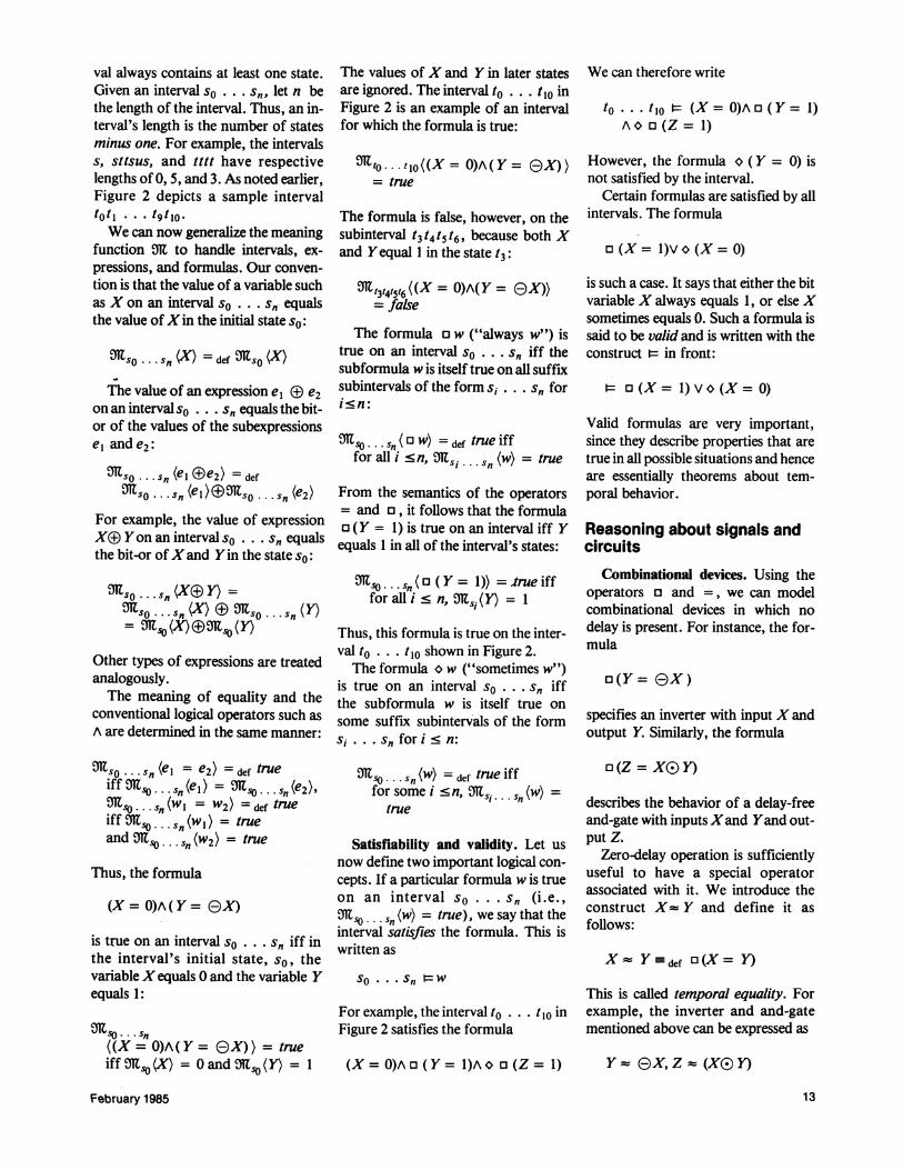
Modeling transistors. We can usetemporal logic to model cmos passtransistors. Certain properties havebeen automatically verified by a theor-em prover for temporal logic. For ex-ample, Figure 3a shows an n-transistorwith three signals, X, Y, and Z. When-ever Xequals 1, Yequals Z. When Xis0, the connection between Y and Z"floats." We can model this by notmentioning what happens between Xand Z. Here is the transistor's specifi-cation, ntran(X, Y,Z):
ntran(X,Y,Z) =defo([X= 1] D[Y= Z])
The p-transistor shown in Figure 3b isanalogously defined. It is active onlywhen X is 0:
ptran(X, Y,Z) =defo([X= 0]D[Y= Z])The circuit in Figure 3c implements
an inverter and is formalized by thepredicate cmosinverter(X, Y).
cmos inverter(X, Y) def[ntran (X, Y,O)Aptran (X, Y, 1)]
Here we use logical-and (A) to com-bine the two transistors into a single,larger device. The correctness of theinverter is given by the following prop-erty:
¢ cmosinverter(X, Y) D(y= EX)
As the following property states, it theinverter's input X rises, the output Yfalls:
¢ [cmos_inverter(X, Y) A tX] D I Y
Figure 4 shows a cmos nand-gate.The following predicate formalizes thedevice's construction:
¢ cmos_nand( W,X, Y,Z) defptran (X,Z, l)Aptran ( Y,Z, 1)Antran(X,Z, W)Antran (Y, W,0)
Figure 3. Cmos circuits. An n-transis-tor (a), a p-transistor (b), and an inverter(c).
The next formula expresses the properbehavior of the nand-gate:
t- cmos_nand(W,X,Y,Z) D[Z - e (XG)Y)]
It is also possible to hide the signal W.This approach to modeling transis-
tors does not include extra bit valuesfor high impedance and transitoryglitches. Instead, these are viewed as
temporal phenomena. It remains to beseen how to properly model sequentialaspects of transistors.
The operator nextIn formulas of the form O w ("next
w"), w is itself a formula. Thus we cantest whether the formula w is true atthe "next time" in an interval. A for-mula Ow is true for an intervalSo . s,n iff the interval has length> 1 (i.e., n 1), and if the subformulaw is true on the subinterval s I . . Sn,obtained by deleting the first state, so:
911sO . .. Sn (O W) = def true iff n 21and Mls1 . .. sS(w) = true
For example, the formula Q (X = 1)is true on an interval so . .. s,S iffn 21 and the variable Xequals 1 in the"next" statesI .
COMPUTER14

Figure 5. An SR-latch.
for alli<n, M1sj+I(X) = E3 ., (X)
Similarly, the formula XdelX is trueiff the signal X is repeatedly fed backto itself. This is logically equivalent toX being stable:
¢ (XdelX) _ (stableX)
Thus, a simple feedback loop can beused in hardware to maintain the valueof a signal.We can use unit delay to implement
different types ofmemory devices. Forinstance, the SR-latch in Figure 5 canbe expressed as
[e (S(3Q)del Q]A [E) (ROQ)del Q]
A generalization of next has theform Qmw and is equivalent tonesting the formula w in m occur-rences of next. For examnple, the for-mula 04 (X = Q Y) is the same as000Q (X = 8 Y); it thereforetests whetherX equals 0 Yin state S4of an interval so . . Sn,
Using next to test interval length. Itis possible to use next to derive con-structs for determining interval length.For example, the formula empty istrue on an interval so . .. s,n iff the in-terval has lengthO (i.e., n = 0). We candefine empty as
empty -def - 0 true
The minimal nonzero length that atemporal interval can have is 1. Wedefine a construct called skip to test forlength 1:
skip def Oempty
The constructs 0 and empty can alsobe used to test for intervals of a par-ticular length. For example, the for-mula 000 empty is true on an in-terval iff the interval has length 3. Ageneralized form of this test is writtenlen(n) and tests for intervals havinglength n:
len(n) - def empty
The formula Oootrue is satis-fied by intervals having a length of atleast three units. The construct min-len (n) is true for an interval at least nunits long:
minlen (n) ddef n true
Unit delay. Suppose that over time,one bit signal X is continuously as-signed to another bit signal Y, but withunit delay. We use the construct XdelY to represent this and define it as
Xdel Y- defo(3 emptyD [(X = 0) 0
(Y= 0)])
The formula is true on an intervalso . .. s, in which for all i<n, thevalue of X is 0 in the state si iff thevalue of Y is 0 in the next state s,+1.Since X and Y are bit signals, it alsofollows that X equals I in the state siiff Yequals I in the state si+ I . The test-'empty ensures that we do not "runoff" the edge of the interval by errone-ously attempting to examine Y's valuein the nonexistent state Sn+ I.The formula ((X) del Xis true on
an interval so . .. Sn iff the variableXis repeatedly complemented from eachstate to its successor:
SO . . . SnI (OX) delXiff
The variables S and R are the circuit'sinputs; the variables Q and Q are theoutputs.
Unit delay can also be used as a pro-gramming construct. The followingformula initializes land Jto 0 and thenkeeps incrementing I by 1 and J by Ifor five time units.
len(5)A(I = O)A(J = 0)A (1+1 delI)A(J+IdelJ)
This is a legal program in Tempuraand results in the behavior shown inFigure 6. We use a generalized form ofdel that permits integer-valued vari-ables.
Transport delay. The unit delaydescribed by the del construct can beextended to treat delays of any fixedduration, known as transport delays:
X deln Y - def o (minlen (n) D[(X = 0) n(Y= 0)1)
The variable n is a fixed natural num-ber indicating the time delay between avalue being input on Xand later beingoutput on Y.Two properties of transport delay
are:Zero delay is the same as temporalequality:
(Xdel Y) = (X- Y)
15February 1985
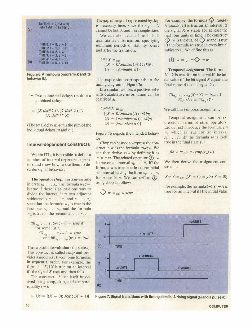
Figure 6. ATempura program (a)and itsbehavior (b).
* Two connected delays result in acombined delay:
t [(XdelmY)A (Ydeln Z)]D(Xdelm+n Z)
(The total delaym + n is the sum of theindividual delays m and n.)
Interval-dependent constructs
Within ITL, it is possible to define anumber of interval-dependent opera-tors and show how to use them to de-scribe signal behavior.
The operator chop. For a given timeinterval so . .. sn, the formula w l; W2is true if there is at least one way todivide the interval into two adjacentsubintervals so . ...s and si . . .Snsuch that the formula w, is true in thefirst one, so . . . si, and the formulaw2 is true in the second, si ... .S
mso . .. Sn(Wl;W2) = true iff
for some ic n,*so . . s,(wl) = trueand Nsi... Sn (w2) = true
The two subintervals share the state si.This constuct is called chop and pro-vides a good way to combine formulasin sequential order. For example, theformula tX; IX is true on an intervaliff the signal Xrises and then falls.The construct tX can itself be de-
rived using chop, skip, and temporalequality (-):
t- tX =_ [(X - O); skip; (X - 1)]
The gap of length 1 represented by skipis necessary here, since the signal Xcannot be both 0 and 1 in a single state.We can also extend t to include
quantitative information, specifyingminimum periods of stability beforeand after the transition:
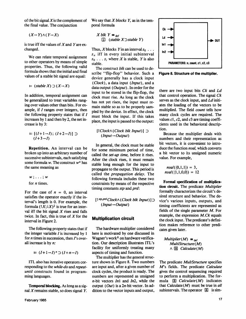
tm,nnX _df[(X - OAminlen (m)); skip;(X = I Aminlen (n)) ]
This expression corresponds to thetiming diagram in Figure 7a.
In a similar fashion, a positive pulsewith quantitative information can bedescribed as
II,m,nX =def
[(X - OAminlen(l)); skip;(X = lAminlen(m)); skip;(X = OAminlen(n))]
Figure 7b depicts the intended behav-ior.Chop can be used to express the con-
struct o w as the formula true;w. Wecan then derive a w by defining it as- oC w. The related operator <1 wis true on an interval so . .. Sn iff theformula w is true in at least one initialsubinterval having the form so . . .sfor some isn. We can defineusing chop as follows:
) W -def W;true
For example, the formula 4> (len(4)A [stable XI) is true on an interval iffthe signal X is stable for at least thefirst four units of time. The construct<> w is the dual of () w and is trueiff the formula w is true in every initialsubinterval. We define this as
m W =def W
Temporal assignment. The formulaX- Y is true for an interval if the ini-tial value of the bit signalXequals thefinal value of the bit signal Y:
s0 .. . s,,(X- Y) = true iffMlo (X) M" (Y)
We call this temporal assignment.
Temporal assignment can be ex-pressed in terms of other operators.Let us first introduce the formula finw, which is true for an intervalSo ... Sn iff the formula w is itselftrue in the final state sn:
fin W def a (emptyDw)
We then derive the assignment con-struct as
XYY def [(X = 0) fln (Y = 0)]
For example, the formula (OX)-Xistrue for an interval iff the initial value
Figure 7. Signal transitions with timing details. A rising signal (a) and a pulse (b).
16 COMPUTER
of the bit signal Xis the complement ofthe final value. The conjunction
(X- Y) A( Y-X)
is true iff the values ofXand Yare ex-changed.
We can relate temporal assignmentto other operators by means of simpleproperties. Thus, the following validformula shows that the initial and finalvalues of a stable bit signal are equal:
= (stable X) D (X-X)
In addition, temporal assignment canbe generalized to treat variables rang-ing over values other than bits. For ex-ample, if I ranges over integers, thenthe following property states that if Iincreases by 1 and then by 2, the net in-crease is by 3:
UI[(+1-I); (I+2-I)] D(I+ 3-I)
Repetition. An interval can bebroken up into an arbitrary number ofsuccessive subintervals, each satisfyingsome formula w. The construct wn hasthe same meaning as
w ;...;w
for n times.
For the case of n = 0, an intervalsatisfies the operator exactly if the in-terval's length is 0. For example, theformula (tX; IX)2 is true for an inter-val iff the bit signal X rises and fallstwice. In fact, this is true ofX for theinterval in Figure 2.
The following property states that ifthe integer variable I is increased by 1for n times in succession, then I's over-all increase is by n:
(I+ 1 I) n D(I+n-I)
ITL also has iterative operators cor-responding to the while-do and repeat-until constructs found in program-ming languages.
Temporal blocking. As long as a sig-nal Xremains stable, so does signal Y.
We say that X blocks Y, as in the tem-poral formula
X blk Y defmII (stable XDstable Y)
Thus, Xblocks Yin an intervals0 ...sn iff in every initial subintervalso ... si where X is stable, Y is alsostable.The construct blk can be used to de-
scribe "flip-flop" behavior. Such adevice generally has a clock input(Clock), a data input (Input), and adata output (Output). In order for theinput to be stored in the flip-flop, theclock must rise. As long as the clockhas not yet risen, the input must re-main stable so as to be properly sam-pled by the device. In effect, the clockmust block the input. If this takesplace, the input is passed to the output:
It ClockA (Clock blk Input) ] D(Input- Output)
In general, the clock must be stablefor some minimum period of time,called the set-up time, before it rises.After the clock rises, it must remainstable long enough for the input topropagate to the output. This period iscalled the propagation delay. Thefollowing formula includes these twoconstraints by means of the respectivetiming constants stp and prd:
[I stPPrdClockA (Clock blk Input)I D(Input-Output)
Multiplication circuit
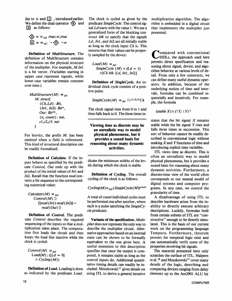
The hardware multiplier consideredhere is motivated by one discussed inWagner's work8 on hardware verifica-tion. Our description illustrates ITL'sfacility for uniformly treating manyaspects of timing and function.The multiplier has the general struc-
ture shown in Figure 8. Two numbersare input and, after a given number ofclock cycles, the product is ready. Thenumbers are represented as unsignedn-bit vectors Inl and In2, while theoutput (Out) is a 2n-bit vector. In ad-dition to the vector inputs and output,
Ck
LdOUT
mln
PARAMETERS: n, count, cl, c2, c3
Figure 8. Structure of the multiplier.
there are two input bits Ck and Ldthat control operation. The signal Ckserves as the clock input, and Ld initi-ates the loading of the vectors to bemultiplied. The field count tells howmany clock cycles are required. Thevalues cl, c2, and c3 are timing coeffi-cients used in the behavioral descrip-tion.
Because the multiplier deals withnumbers and their representation asbit vectors, it is convenient to intro-duce the function nval, which convertsa bit vector to its unsigned numericvalue. For example,
nval((0,1,1)) = 3,nval((1,1,0,0)) = 12
Formal specification of multiplica-tion circuit. The predicate Multiplierformally characterizes the circuit's de-sired structure and behavior. The de-vice's various inputs, outputs, andtiming coefficients are represented asfields of the single parameter M. Forexample, the expression M.Ck equalsthe clock input. The predicate's defini-tion makes reference to other predi-cates given later.
Muftiplier(M) defMultiStructure(M)A [11 Calculate(M)
The predicate MultStructure specifiesMs fields. The predicate Calculategives the control sequencing requiredto perform a multiplication. The for-mula [ Calculate(M) indicatesthat Calculate (M) must be true in allsubintervals. The operator (Q is sim-
February 1985 17
ilar to o and CD , introduced earlier.We define the dual operator I> and[E as follows:
4 W def true;w;true
( W =def 4<8 W
Definition of MultStructure. Thedefinition of MultStructure containsinformation on the physical structureof the multiplier. For example, M.Inlis a bit vector. (Variables starting inupper case represent signals, whilelower-case variables remain constantover time.)
MultStructure(M) defM: struct[
(Ck,Ld): Bit,(Inl, In2): Bitn,Out: Bit2",(n, count): nat,cl,c2,c3: nat
For brevity, the prefix M. has beenomitted when a field is referenced.This kind of structural description canbe readily formalized.
Definition of Calculate. If the in-puts behave as specified by the predi-cate Control, Out ends up with theproduct of the initial values of Inl andIn2. Recall that the function nval con-verts a bit sequence to the correspond-ing numerical value:
Calculate(M) defControl(M) D
([nval(In 1) nval(n2)) -nval(Out) )
Definition of Control. The predi-cate Control describes the requiredsequencing of the inputs so that a mul-tiplication takes place. The computa-tion first loads the circuit and thenkeeps the load line inactive while theclock is cycled:
Control(M) defLoad(M); ([Ld : 0]A Cycling(M))
Definition of Load. Loading is doneas indicated by the predicate Load.
The clock is cycled as given by thepredicate SingleCycle. The control sig-nal Ld starts with the value 1. We use ageneralized form of the blocking con-struct blk to specify that the signalsLd, Inl, and In2 are all initially stableas long as the clock input Ck is. Thisensures that their values can be proper-ly sampled by the device:
Load(M) -defSingleCycle (M) A (Ld = 1)A[Ck b/k (Ld, Inl, In2)]
Definition of SingleCycle. An in-dividual clock cycle consists of a posi-tive pulse:
SingleCycle(M) =def t cl,c2,c3 Ck
The clock signal rises from 0 to 1 andthen falls back to 0. The three times in-
Viewing time as discrete may bean unrealistic way to modelphysical phenomena, but itprovides a sound basis for
reasoning about many dynamicactivities.
dicate the minimum widths of the lev-els during which the clock is stable.
Definition of Cycling. The overallcycling of the clock is as follows:
Cycling(M) 3def (SingleCycle (M))counl
A total of count individual cycles mustbe performed one after another, whereeach is a pulse satisfying the SingleCy-cle predicate.
Variants of the specification. Multi-plier does not represent the only way todescribe the multiplier circuit. Alter-native approaches based on an internalstate can be shown to be formallyequivalent to the one given here. Auseful extension to this descriptionspecifies that once the output is com-puted, it remains stable as long as thecontrol inputs do. Additional quanti-tative timing details can readily be in-cluded. Moszkowski'7 gives details onusing ITL to derive a general iterative
multiplication algorithm. The algo-rithm is embedded in a digital circuitthat implements the multiplier justpresented.
( ompared with conventional^-HIDLs, the approach used herepermits direct specification and rea-soning about signal, device, and algo-rithm behavior at various levels of de-tail. From only a few constructs, wecan define many useful dynamic oper-ators. In addition, because of theunderlying notion of time and inter-vals, formulas can be combined se-quentially and iteratively. For exam-ple, the formula
(stable X) A (t Y; I Y) 3
states that the bit signal X remainsstable while the bit signal Y rises andfalls three times in succession. Thissort of behavior cannot be readily de-scribed in conventional logic withoutmaking Xand Yfunctions of time andintroducing explicit time variables.ITL views time as discrete. This is
often an unrealistic way to modelphysical phenomena, but it provides asound basis for reasoning about manydynamic activities. Furthermore, adiscrete-time view of the world oftencorresponds to our mental model ofdigital systems and computer pro-grams. In any case, we control thegranularity of time.A disadvantage of using ITL to
describe hardware arises from the in-ability to directly execute arbitrarydescriptions. Luckily, formulas builtfrom certain subsets of ITL are "con-structive" enough to be directly simu-lated. This is the basis of our currentwork on the programming languageTempura. Furthermore, theoremprovers for temporal logic exist andcan automatically verify some of theproperties involving bit signals.The material presented here only
scratches the surface of ITL. Halpernet al. 18 and Moszkowski 17 cover manydetails of the logic, describing andcomparing devices ranging from delayelements up to the Am2901 ALU bit
18 COMPUTER
slice developed by Advanced MicroDevices, Inc. Moszkowski6 also showshow to program directly in temporallogic. Future work will involve devel-oping the programming languageTempura and examining microproces-sors, buses and protocols, DMA, firm-ware, and instruction sets, as well asthe combined semantics of hardwareand software. O
Acknowledgments
Many thanks to John McCarthyand Zohar Manna for the support andguidance they gave as this researchdeveloped. Joseph Halpern providedvaluable insights into ITL's semanticsand theoretical complexity. If it hadnot been formy friends at SiemensAGand the Polish Academy of Sciences, itis unlikely I would have undertakenthis investigation. Late-night trans-atlantic discussions with Mike Gordonhelped provide a sense of intrigue.Highest-quality chocolate and en-thusiasm were always available fromthe Trischlers. Finally, comments byRoger Hale and the referees provedvery useful during the revision of thisarticle.
This work was done as part of theauthor's doctoral dissertation at Stan-ford University and was supported inpart by the National Science Founda-tion under a Graduate Fellowship,Grants MCS79-09495, MCS80-06930,and MCS81-11586; by DARPA underContract N00039-82-C-0250; by theU.S. Air Force Office of Scientific Re-search under Grant AFOSR-81-0014;and by the British Science and Engi-neering Research Council.
References
1. M. R. Barbacci, "Instruction Set Pro-cessor Specifications (ISPS): TheNotation and its Applications," IEEETrans. Comp., Vol. C-30, No. 1, Jan.1981, pp. 24-40.
2. A. C. Parker and J. J. Wallace,"SLIDE: An I/O Hardware Descrip-
tion Language," IEEE Trans. Comp.,Vol. C-30, No. 6, June 1981, pp.423-439.
3. S.Y.H. Su, C. Huang, and P.Y.K.Fu, "A New Multi-level HardwareDesign Language (LALSD II) andTranslator," Proc. 5th Int'l Conf.Computer Hardware DescriptionLanguages, Kaiserslautern, West Ger-many, 1981, pp. 155-169.
4. Z. Manna and A. Pnueli, "Verifica-tion of Concurrent Programs: TheTemporal Framework," in The Cor-rectness Problem in Computer Sci-ence, R. S. Boyer and J. S. Moore,eds., Academic Press, New York,1981, pp. 215-273.
5. N. Rescher and A. Urquart, TemporalLogic, Springer-Verlag, New York,1971.
6. B. Moszkowski, "Executing Tem-poral Logic Programs," tech. report55, University of Cambridge, Compu-ter Laboratory, England, Aug. 1984.
7. M. Gordon, "Register Transfer Sys-tems and Their Behaviour," Proc.Fifth Int'l ConJ: ComputerHardwareDescription Languages, Kaiserslau-tern, West Germany, Sept. 1981, pp.23-36.
8. T. Wagner, "Hardware Verification,"tech. report STAN-CS-77-632, Stan-ford University, Sept. 1977.
9. P. Meinen, "Formal Semantic De-scription of Register Transfer Lan-guage Elements and Mechanized Sim-ulator Construction," Proc. 4th Int'lSymp. Computer Hardware Descrip-tion Languages, Palo Alto, Calif.,Oct. 1979, pp. 69-74.
10. Y. Malachi and S. S. Owicki, "Tem-poral Specifications of Self-timed Sys-tems," in VLSI Systems and Com-putations, H. T. Kung et al., eds.,Computer Science Press, Rockville,Md., 1981, pp. 203-212.
11. G. V. Bochmann, "Hardware Specifi-cation with Temporal Logic: An Ex-ample," IEEE Trans. Comp., Vol.C-31, No. 3, Mar. 1982, pp. 223-231.
12. M. Fujita, H. Tanaka, and T. Moto-Oka, "Temporal Logic Based Hard-ware Description and its Verificationwith Prolog," New Generation Com-puting, Vol. 1, 1983, pp. 195-203.
13. S. Leinwand and T. Lamdan, "Alge-braic Analysis of NondeterministicBehavior," Proc. 17th Design Auto-mation Conf., Minneapolis, June1980, pp. 483-493.
14. R. E. Shostak, "Formal Verificationof Circuit Designs," Proc. 6th Int'lConf. Computer Hardware Descrip-tion Languages, 1983, pp. 13-30.
15. H. B. Enderton, A Mathematical In-troduction to Logic, Academic Press,New York, 1972.
16. Z. Manna, Mathematical Theory ofComputation, McGraw-Hill, NewYork, 1974.
17. B. Moszkowski, "Reasoning AboutDigital Circuits," tech. report STAN-CS-83-970, Stanford University, 1983.
18. J. Halpem, Z. Manna, and B. Mosz-kowski, "A Hardware SemanticsBased on Temporal Intervals," Proc.10th Int'l Colloq. Automata, Lan-guages and Programming, Barcelona,Spain, Springer-Verlag, Berlin, 1983,pp. 278-291.
Ben Moszkowski is a postdoctoral re-searcher at the Computer Laboratory,Cambridge University, England. His cur-rent research interests include hardwaresemantics and programming languagesbased on temporal logic. He received his BSdegree in mathematics/computer sciencefrom the University of California at LosAngeles and his PhD degree in computerscience from Stanford University. Theauthor's current address is Computer Lab-oratory, Cambridge University, Corn Ex-change Street, Cambridge CB2 3QG,England.
February 1985 19