a-t armaturen- a-t technik gmbh turbine bypass · pdf filevelocity inside the boiler keeps up...
TRANSCRIPT
Turbine BypassSystems
Issue: January 2012 0
A-T®
A-T ARMATUREN - TECHNIK GMBH
A-T® A-T ARMATUREN -
TECHNIK GMBH
Turbine Bypass Systems
Turbine BypassSystems
Issue: January 2012 1
A-T®
A-T ARMATUREN - TECHNIK GMBH
................................................. 2
................................................. 3
................................................. 4
................................................... 5................................................. 6................................................. 7................................................. 8................................................. 9
................................................... 10.................................................. 11................................................. 12................................................. 13................................................. 14
................................................. 15
................................................. 16
................................................. 17
................................................. 18
1. Turbine Bypass System2. Scope of delivery3. Typical shapes4. Steam Conditioning Valves type DZE
4.1 Overview4.2 Application4.3 Sound emisson and reduction measures4.4 Primary reduction measures4.5 Secondary sound reduction
5. Spraywater Control Valves type ESV5.1 Overview5.2 Application
6. Hydraulic Power Unit HPU7. Pneumatic Control System8. Bringing into service9. Calculation
9.1 Steam Conditioning Valve9.2 Spraywater Control/Stop Valve
10. Summary of technical data11. Installations of A-T Bypass Systems
Content
Turbine BypassSystems
Issue: January 2012 2
A-T®
A-T ARMATUREN - TECHNIK GMBH
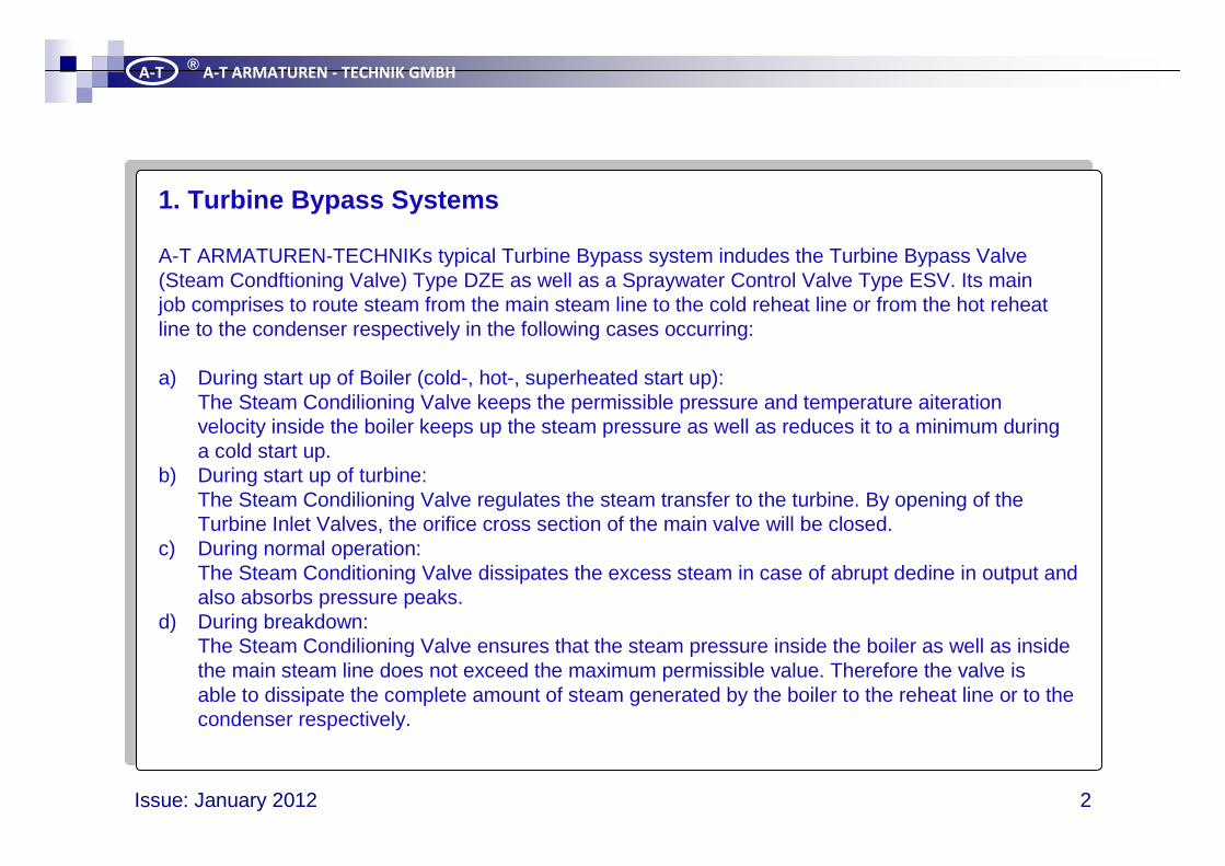
A-T ARMATUREN-TECHNIKs typical Turbine Bypass system indudes the Turbine Bypass Valve(Steam Condftioning Valve) Type DZE as well as a Spraywater Control Valve Type ESV. Its mainjob comprises to route steam from the main steam line to the cold reheat line or from the hot reheatline to the condenser respectively in the following cases occurring:
a) During start up of Boiler (cold-, hot-, superheated start up):The Steam Condilioning Valve keeps the permissible pressure and temperature aiterationvelocity inside the boiler keeps up the steam pressure as well as reduces it to a minimum duringa cold start up.
b) During start up of turbine:The Steam Condilioning Valve regulates the steam transfer to the turbine. By opening of theTurbine Inlet Valves, the orifice cross section of the main valve will be closed.
c) During normal operation:The Steam Conditioning Valve dissipates the excess steam in case of abrupt dedine in output andalso absorbs pressure peaks.
d) During breakdown:The Steam Condilioning Valve ensures that the steam pressure inside the boiler as well as insidethe main steam line does not exceed the maximum permissible value. Therefore the valve isable to dissipate the complete amount of steam generated by the boiler to the reheat line or to thecondenser respectively.
1. Turbine Bypass Systems
Turbine BypassSystems
Issue: January 2012 3
A-T®
A-T ARMATUREN - TECHNIK GMBH
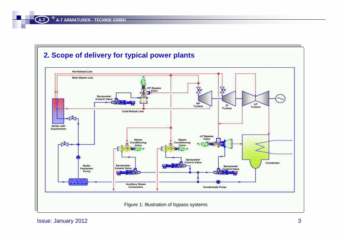
2. Scope of delivery for typical power plants
Figure 1: Illustration of bypass systems
Turbine BypassSystems
Issue: January 2012 4
A-T®
A-T ARMATUREN - TECHNIK GMBH
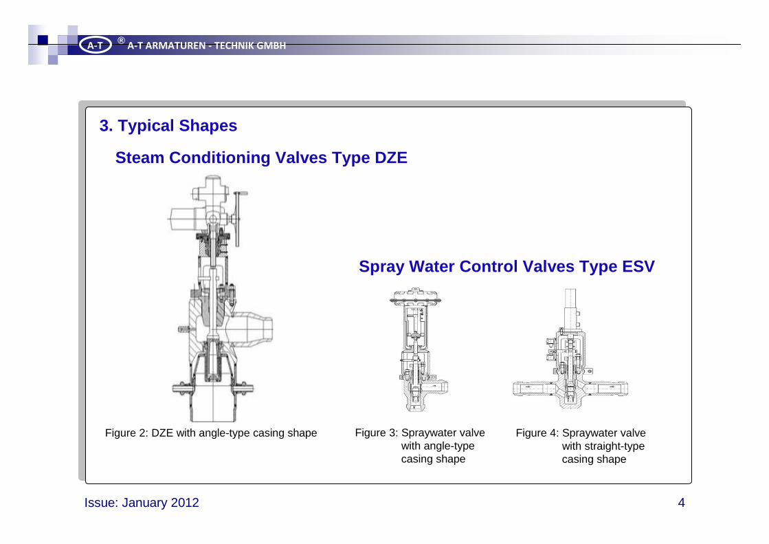
Steam Conditioning Valves Type DZE
Spray Water Control Valves Type ESV
3. Typical Shapes
Figure 2: DZE with angle-type casing shape Figure 3: Spraywater valvewith angle-typecasing shape
Figure 4: Spraywater valvewith straight-typecasing shape
Turbine BypassSystems
Issue: January 2012 5
A-T®
A-T ARMATUREN - TECHNIK GMBH
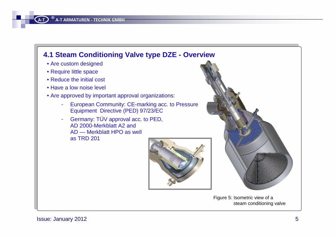
• Are custom designed• Require Iittle space• Reduce the initial cost• Have a low noise level• Are approved by important approval organizations:
- European Community: CE-marking acc. to PressureEquipment Directive (PED) 97/23/EC
- Germany: TÜV approval acc. to PED,AD 2000-Merkblatt A2 andAD — Merkblatt HPO as wellas TRD 201
4.1 Steam Conditioning Valve type DZE - Overview
Figure 5: Isometric view of asteam conditioning valve
Turbine BypassSystems
Issue: January 2012 6
A-T®
A-T ARMATUREN - TECHNIK GMBH
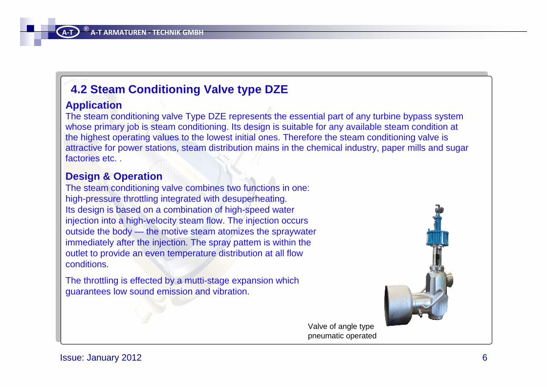
ApplicationThe steam conditioning valve Type DZE represents the essential part of any turbine bypass system whose primary job is steam conditioning. Its design is suitable for any available steam condition at the highest operating values to the lowest initial ones. Therefore the steam conditioning valve is attractive for power stations, steam distribution mains in the chemical industry, paper mills and sugar factories etc. .
Design & OperationThe steam conditioning valve combines two functions in one: high-pressure throttling integrated with desuperheating.Its design is based on a combination of high-speed waterinjection into a high-velocity steam flow. The injection occursoutside the body — the motive steam atomizes the spraywaterimmediately after the injection. The spray pattem is within theoutlet to provide an even temperature distribution at all flowconditions.
The throttling is effected by a mutti-stage expansion whichguarantees low sound emission and vibration.
4.2 Steam Conditioning Valve type DZE
Valve of angle typepneumatic operated
Turbine BypassSystems
Issue: January 2012 7
A-T®
A-T ARMATUREN - TECHNIK GMBH
During the pressure reduction in a valve, a pari: of the energy of the process medium is converted into sound energy and radiates both from the valve itself, but also primarily from the pipe system. Guidelines as well as health and safety at work legislation are pushing towards quiet valve solutions; sound level requirements of 70 to 75 dB(A) are not unusual.
The increasing demand for lower sound emissions from process plants often come up against not only economic boundaries but also technical limitations. Low-noise valves require not only more complex inner parts, but often also a longer body. This is refiected in significantly higher costs. Extreme levels of sound emission are always also an expression of mechanical stress. Whenever considering sound emission it must always be come in mind that the sound is in fact generated in the valve, the sound radiation actually emanates from the downstream pipe system.
With reference to sound generation, a differentiation must be made here between incompressible and compressible media.
For gases or vapours the main cause of sound emission is, for subcritical expansion, the partial conversion of energy into sound energy. Due to the significantiy higher flow velocities compared with liquids, the sound level increases sharply with rising pressure difference. Even for relatively small valves, it can already lie above permissible limits and cause impairments to health. If the pressure ratio across the control valve exceeds the XT value, shock waves are the main cause of sound emission in the expansion zone.
4.3 Sound emission and reduction measures
Turbine BypassSystems
Issue: January 2012 8
A-T®
A-T ARMATUREN - TECHNIK GMBH
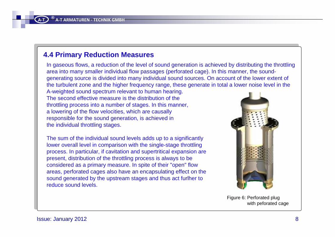
In gaseous flows, a reduction of the level of sound generation is achieved by distributing the throttling area into many smaller individual flow passages (perforated cage). In this manner, the sound-generating source is divided into many individual sound sources. On account of the lower extent of the turbulent zone and the higher frequency range, these generate in total a lower noise level in the A-weighted sound spectrum relevant to human hearing.The second effective measure is the distribution of thethrottling process into a number of stages. In this manner,a lowering of the flow velocities, which are causallyresponsible for the sound generation, is achieved inthe individual throttling stages.
The sum of the individual sound levels adds up to a significantlylower overall level in comparison with the single-stage throttlingprocess. In particular, if cavitation and supertritical expansion arepresent, distribution of the throttling process is always to beconsidered as a primary measure. In spite of their "open" flowareas, perforated cages also have an encapsulating effect on thesound generated by the upstream stages and thus act furlher toreduce sound levels.
4.4 Primary Reduction Measures
Figure 6: Perforated plugwith peforated cage
Turbine BypassSystems
Issue: January 2012 9
A-T®
A-T ARMATUREN - TECHNIK GMBH
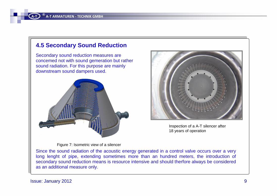
Secondary sound reduction measures areconcemed not with sound gemeration but rathersound radiation. For this purpose are mainlydownstream sound dampers used.
Since the sound radiation of the acoustic energy generated in a control valve occurs over a very long lenght of pipe, extending sometimes more than an hundred meters, the introduction of secondary sound reduction means is resource intensive and should therfore always be considered as an additional measure only.
4.5 Secondary Sound Reduction
Figure 7: Isometric view of a silencer
Inspection of a A-T silencer after18 years of operation
Turbine BypassSystems
Issue: January 2012 10
A-T®
A-T ARMATUREN - TECHNIK GMBH
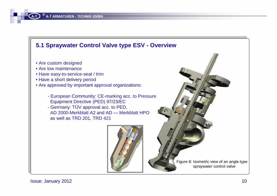
• Are custom designed • Are low maintenance • Have easy-to-service-seat / trim • Have a short delivery period• Are approved by important approval organizations:
- European Community: CE-marking acc. to PressureEquipment Directive (PED) 97/23/EC
- Gerrnany: TÜV approval acc. to PED,AD 2000-Merkblatt A2 and AD — Merkblatt HPOas well as TRD 201, TRD 421
5.1 Spraywater Control Valve type ESV - Overview
Figure 8: Isometric view of an angle-typespraywater control valve

Turbine BypassSystems
Issue: January 2012 11
A-T®
A-T ARMATUREN - TECHNIK GMBH
ApplicationSpraywater control valve Type ESV perceives itseif as final control element to provide service spraywater to the steam conditioning valve for steam temperature control. Its design is based on the operating values of the steam conditioning valve to ensure a consistent and reliable operation.
DesignSpraywater control valve Type ESV is designed for all severeservice spraywater applications. Its basic design is characterized by:
• solid and die-forged body • wear resistant seat and plug • low-friction stem sealing • static double sealing via seat and stern seal • perforated cylinder
The design of the control elements can be single-stage as well asmulti-stage, depending on the given operating values.
In case of impurities in the service spraywater, the inner trim will beprotected against coarse particles by the perforated cylinder. If themedium also contains fine particles, we prefer to precede a strainer.
5.2 Spraywater Control Valve type ESV
Valve of angle typepneumatic operated
Turbine BypassSystems
Issue: January 2012 12
A-T®
A-T ARMATUREN - TECHNIK GMBH
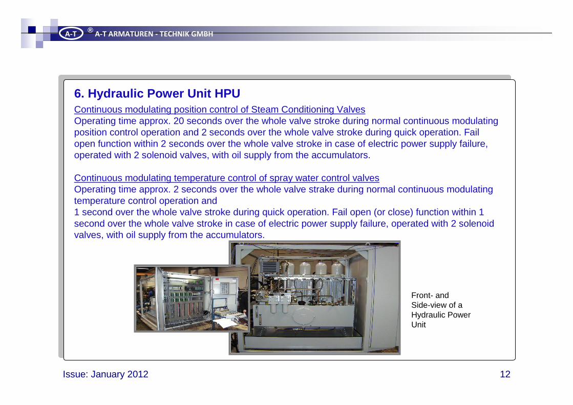
Continuous modulating position control of Steam Conditioning Valves Operating time approx. 20 seconds over the whole valve stroke during normal continuous modulating position control operation and 2 seconds over the whole valve stroke during quick operation. Fail open function within 2 seconds over the whole valve stroke in case of electric power supply failure, operated with 2 solenoid valves, with oil supply from the accumulators.
Continuous modulating temperature control of spray water control valves Operating time approx. 2 seconds over the whole valve strake during normal continuous modulating temperature control operation and 1 second over the whole valve stroke during quick operation. Fail open (or close) function within 1 second over the whole valve stroke in case of electric power supply failure, operated with 2 solenoid valves, with oil supply from the accumulators.
6. Hydraulic Power Unit HPU
Front- andSide-view of aHydraulic PowerUnit
Turbine BypassSystems
Issue: January 2012 13
A-T®
A-T ARMATUREN - TECHNIK GMBH
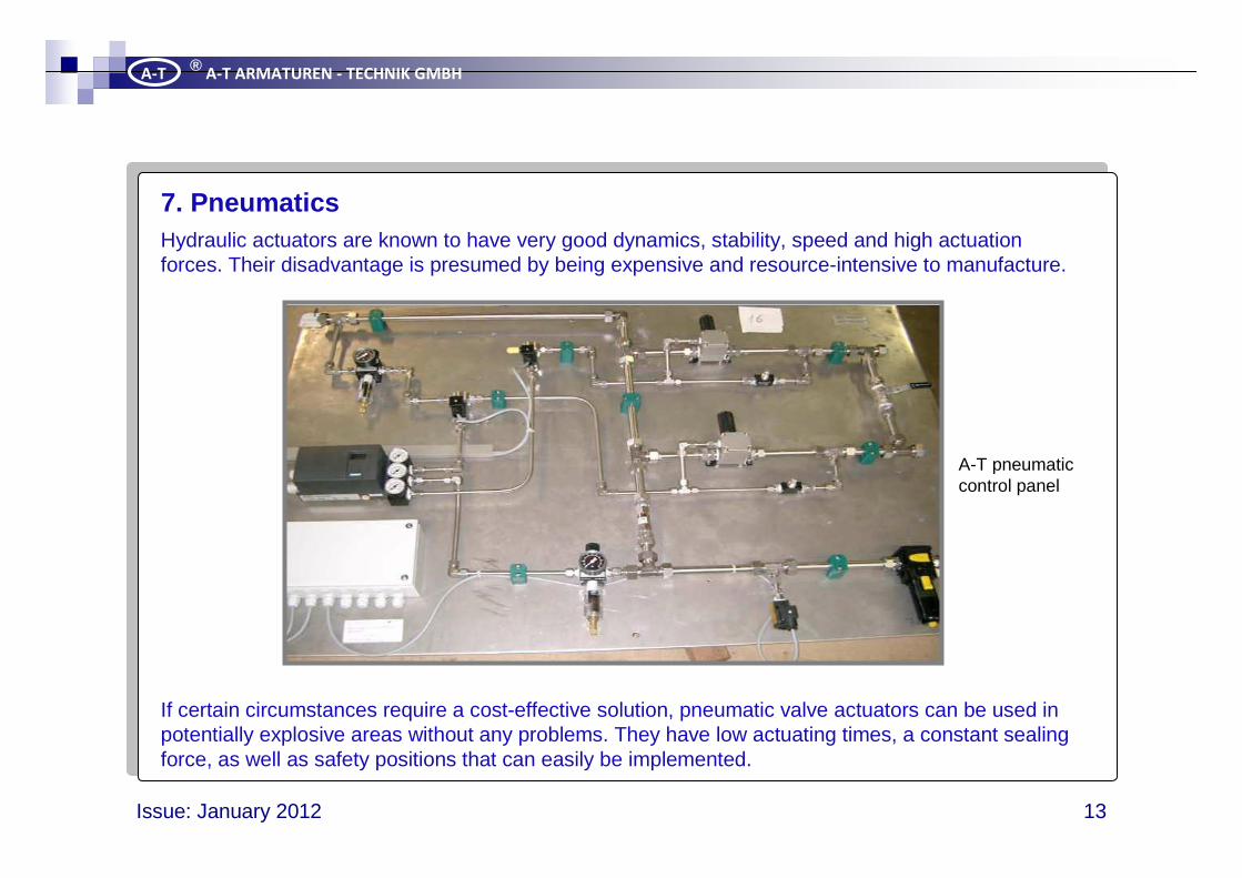
Hydraulic actuators are known to have very good dynamics, stability, speed and high actuation forces. Their disadvantage is presumed by being expensive and resource-intensive to manufacture.
If certain circumstances require a cost-effective solution, pneumatic valve actuators can be used in potentially explosive areas without any problems. They have low actuating times, a constant sealing force, as well as safety positions that can easily be implemented.
7. Pneumatics
A-T pneumaticcontrol panel
Turbine BypassSystems
Issue: January 2012 14
A-T®
A-T ARMATUREN - TECHNIK GMBH
InstallationSteam Conditioning In general, the steam conditioning valve can be installed in anyValve position. We recommend the installation with horizontal inlet
and vertical outlet because no drainage points will be required.In case of any other installation position, drainage points willbe required. All oil lines leading to the hydraulic cylinder mustbe laid free of tension and have to be equipped wilh air reliefvalves.
Spraywater Control In general, the spraywater contol valve can be installed in anyValve: position. All oil lines leading to the hydraulic cylinder must be
laid free of tension and have to be equiped wich air relief valves.
Electro-hydraulic The hydraulic power unit has to run a performance test in theSystem: factory. The adjustment will be made within the entire system.
AdjustmentSteam Conditioning The stroke is adjusted during assembly in the factory, but canValve: also be readjusted at site.
Spraywater Control The stroke is adjusted during assembly in the factory.Valve:
Electro-hydraulic The hydraulic power unit has to run a performance test in theSystem: factory. The adjustment will be made within the entire system.
8. Bringing into service
Turbine BypassSystems
Issue: January 2012 15
A-T®
A-T ARMATUREN - TECHNIK GMBH
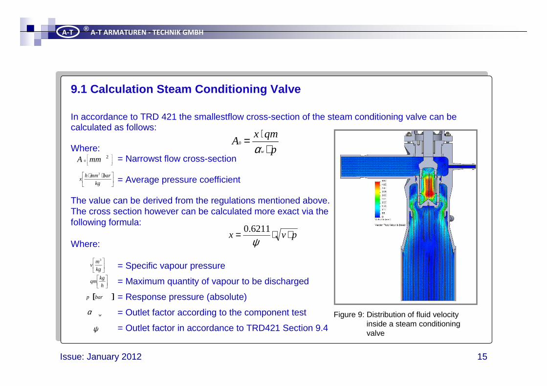
9.1 Calculation Steam Conditioning Valve
In accordance to TRD 421 the smallestflow cross-section of the steam conditioning valve can be calculated as follows:
Where:= Narrowst flow cross-section
= Average pressure coefficient
The value can be derived from the regulations mentioned above. The cross section however can be calculated more exact via thefollowing formula:
Where:
= Specific vapour pressure
= Maximum quantity of vapour to be discharged
= Response pressure (absolute)
= Outlet factor according to the component test
= Outlet factor in accordance to TRD421 Section 9.4
p
qmxA
w ⋅⋅=
α0
20 mmA
⋅⋅kg
barmmhx
2
pvx ⋅⋅=ψ6211.0
kg
mv
3
[ ]barp
ψ
h
kgqm
wα Figure 9: Distribution of fluid velocityinside a steam conditioningvalve
Turbine BypassSystems
Issue: January 2012 16
A-T®
A-T ARMATUREN - TECHNIK GMBH
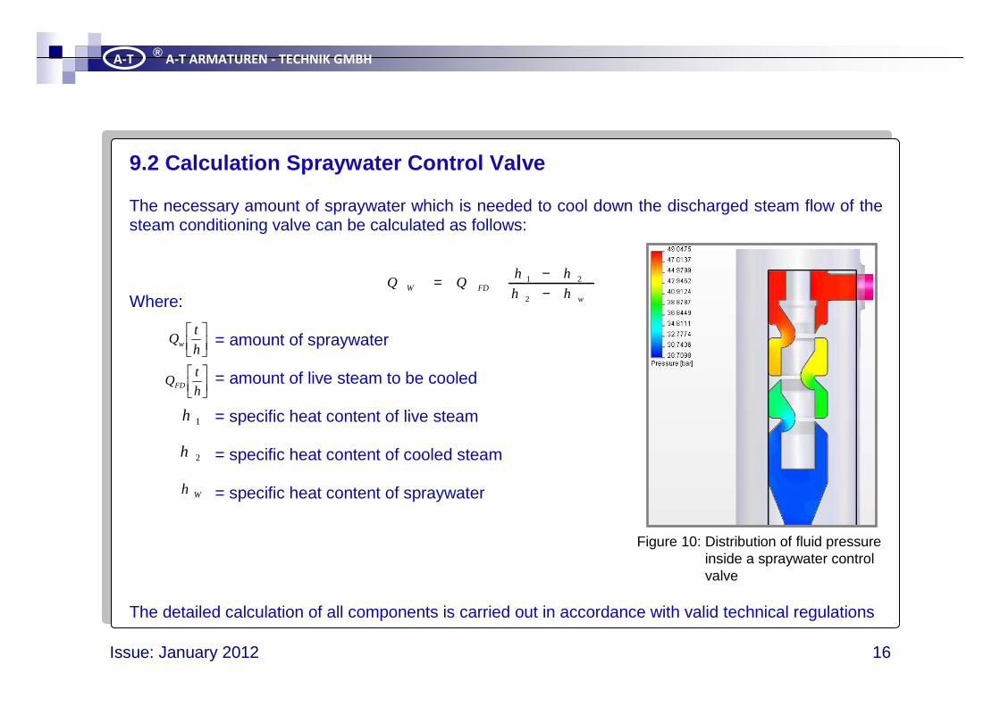
9.2 Calculation Spraywater Control Valve
The necessary amount of spraywater which is needed to cool down the discharged steam flow of the steam conditioning valve can be calculated as follows:
Where:
= amount of spraywater
= amount of live steam to be cooled
= specific heat content of live steam
= specific heat content of cooled steam
= specific heat content of spraywater
The detailed calculation of all components is carried out in accordance with valid technical regulations
wFDW hh
hhQQ
−−=
2
21
h
tQw
h
tQFD
1h
2h
Wh
Figure 10: Distribution of fluid pressureinside a spraywater controlvalve
Turbine BypassSystems
Issue: January 2012 17
A-T®
A-T ARMATUREN - TECHNIK GMBH
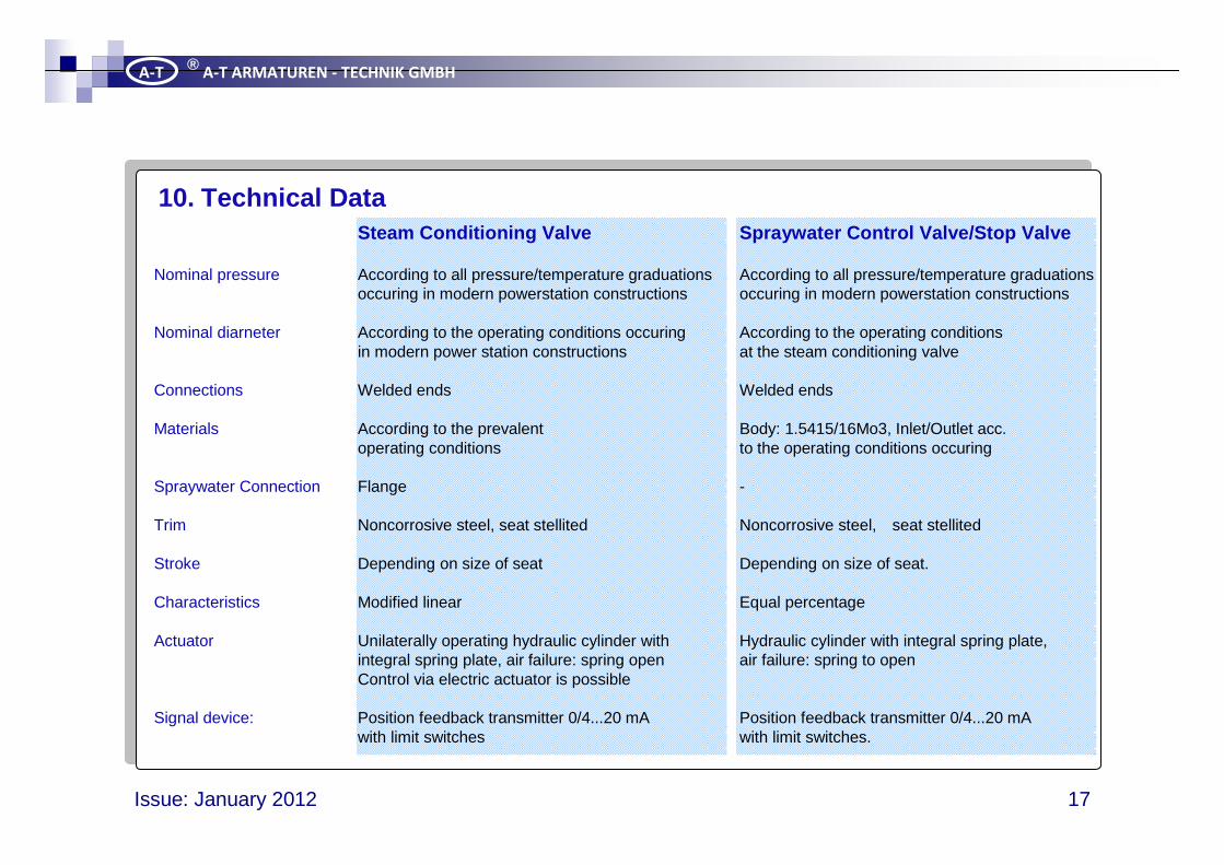
10. Technical DataSteam Conditioning Valve Spraywater Control Valve/St op Valve
Nominal pressure According to all pressure/temperature graduations According to all pressure/temperature graduationsoccuring in modern powerstation constructions occuring in modern powerstation constructions
Nominal diarneter According to the operating conditions occuring According to the operating conditionsin modern power station constructions at the steam conditioning valve
Connections Welded ends Welded ends
Materials According to the prevalent Body: 1.5415/16Mo3, Inlet/Outlet acc.operating conditions to the operating conditions occuring
Spraywater Connection Flange -
Trim Noncorrosive steel, seat stellited Noncorrosive steel, seat stellited
Stroke Depending on size of seat Depending on size of seat.
Characteristics Modified linear Equal percentage
Actuator Unilaterally operating hydraulic cylinder with Hydraulic cylinder with integral spring plate,integral spring plate, air failure: spring open air failure: spring to openControl via electric actuator is possible
Signal device: Position feedback transmitter 0/4...20 mA Position feedback transmitter 0/4...20 mAwith limit switches with limit switches.
Turbine BypassSystems
Issue: January 2012 18
A-T®
A-T ARMATUREN - TECHNIK GMBH
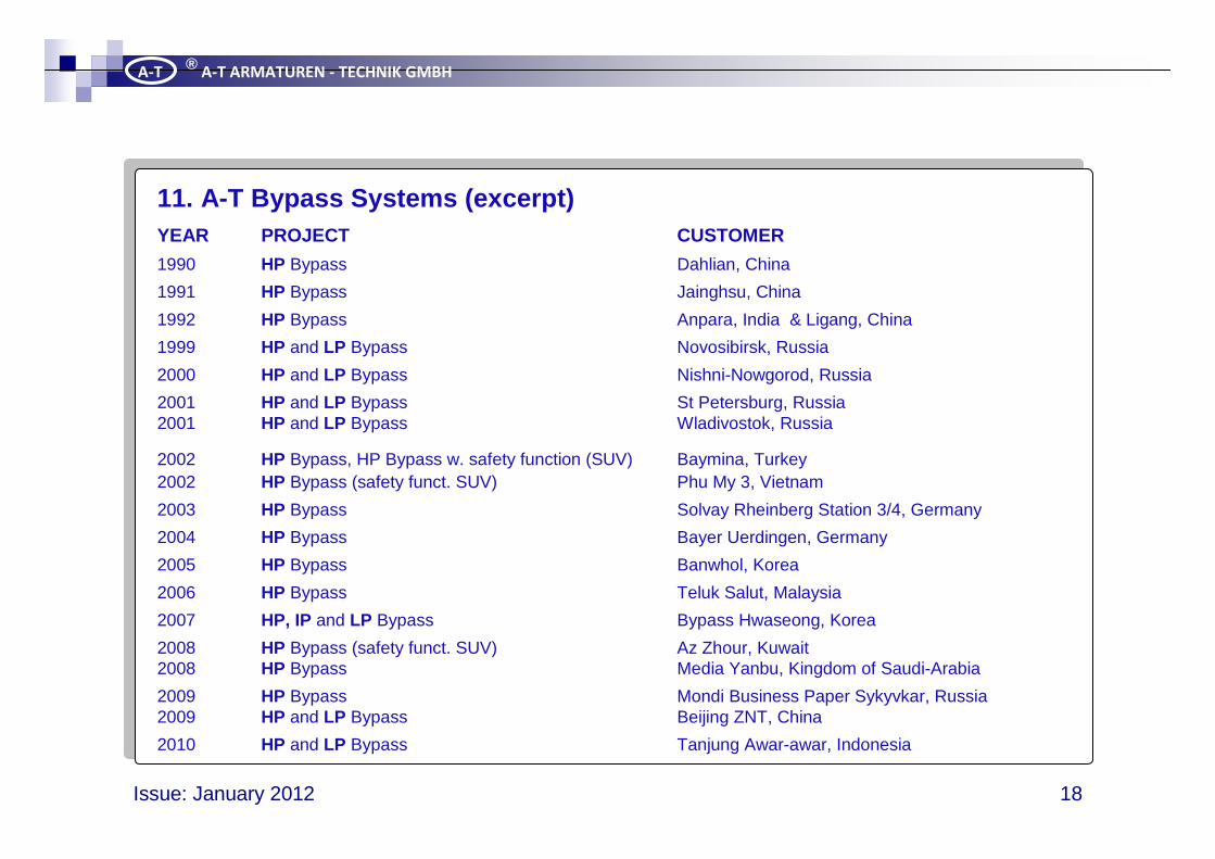
11. A-T Bypass Systems (excerpt)YEAR PROJECT CUSTOMER
1990 HP Bypass Dahlian, China
1991 HP Bypass Jainghsu, China
1992 HP Bypass Anpara, India & Ligang, China
1999 HP and LP Bypass Novosibirsk, Russia
2000 HP and LP Bypass Nishni-Nowgorod, Russia
2001 HP and LP Bypass St Petersburg, Russia2001 HP and LP Bypass Wladivostok, Russia
2002 HP Bypass, HP Bypass w. safety function (SUV) Baymina, Turkey2002 HP Bypass (safety funct. SUV) Phu My 3, Vietnam
2003 HP Bypass Solvay Rheinberg Station 3/4, Germany
2004 HP Bypass Bayer Uerdingen, Germany
2005 HP Bypass Banwhol, Korea
2006 HP Bypass Teluk Salut, Malaysia
2007 HP, IP and LP Bypass Bypass Hwaseong, Korea
2008 HP Bypass (safety funct. SUV) Az Zhour, Kuwait 2008 HP Bypass Media Yanbu, Kingdom of Saudi-Arabia
2009 HP Bypass Mondi Business Paper Sykyvkar, Russia 2009 HP and LP Bypass Beijing ZNT, China
2010 HP and LP Bypass Tanjung Awar-awar, Indonesia
Turbine BypassSystems
Issue: January 2012 19
A-T®
A-T ARMATUREN - TECHNIK GMBH
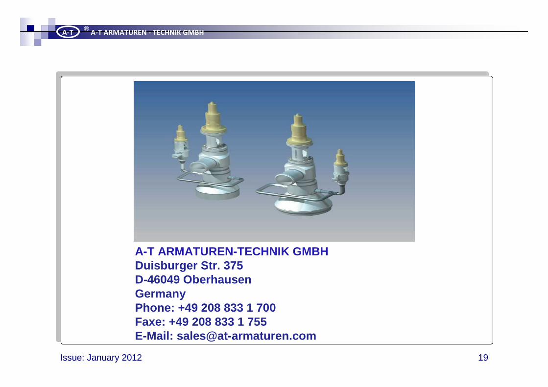
A-T ARMATUREN-TECHNIK GMBH Duisburger Str. 375 D-46049 Oberhausen Germany Phone: +49 208 833 1 700 Faxe: +49 208 833 1 755 E-Mail: [email protected]
Back Cover