a spreadsheet approach to diverter design calculations · a spreadsheet approach to diverter design...
TRANSCRIPT
~ J
A Spreadsheet Approach to Diverter Design Calculations by Adam T Bourgoyne Jr Louisiana Stale UnWersity
ABSTRACT
Diverter Systems must be designed to provide back pressures which will not result in fracture at the conductor casing seat The system design loads are generally based on a shallow gas flow encountered prior to setting surface casing Calculation of the pressure at various points in a diverter system is complicated by sonic flow at the exit by unusually rapid fluid acceleration in some parts of the system by temperature changes and by the possible presence of more than one phase A recent paper presented at the European Well Control Conference (Bourgoyne 1992) presented a new empirical correlation for predicting sonic exit pressures during multi-phase flow This correlation was based on experimental data carried out in 8 inch (0203 m) and 10 inch (0254 m) model diverter systems The practical use of the calculation methods presented in this previous paper is now illustrated using a spreadsheet approach
INTRODUCTION
A key element of shallow gas well control is the selection of appropriate conductor casing setting depth that works well with the rig diverter system for the maximum likely formation pressure and productivity in the area of interest Beck Langlinais and Bourgoyne (1987) recommended that the diverter and casing should be designed using a systems analysis approach that considers the gas reservoir borehole casing and diverter linked together as a single hydraulic system A systems analysis procedure (Brown and Beggs(1977) Crouch and Pack (1980) and Oark and Perkins (1980) permits the simultaneous calculation of steady state pressures throughout the well and diverter system A similar approach was recently presented indetail in API RP 64 (1991)
One of the problems encountered when using a systems analysis procedure is the need for an accurate prediction of the pressures occurring in the diverter system at potentially high gas flow rates Calculation of the pressure at various points in a diverter system is complicated by sonic flow at the exit by unusually rapid fluid acceleration in some parts of the system by temperature changes and by the possible presence of more than one phase Conventional equations and computer algorithms used by petroleum engineers to analyze producing wells cannot be applied with any confidence Recently experiments involving two-phase (gas-water) flow were carried out in 8 inch (0203 m ) and 10 inch (0254 m) model diverter systems at rates sufficient to achieve sonic flow (Bourgoyne 1992) An improved algorithm for calculating pressures and fluid velocities at various points in a diverter system was developed based on this experimental study
RECOMMENDED ALGORITHM
The recommended diverter design calculations require the use of equations describing (1) sonic exit pressure (2) flowing pressure gradients in the diverter and well (3) formation productivity (4) formation fracture gradient and (5) erosion middot
Sonic Exit Conditions
The limiting (sonic) velocity at the vent line exit v e can be computed for any fluid using
1 v =-- (1) c JPc
where r is the density of the fluid and c is the compressibility of the fluid For liquids the density p and compressibility c can be assumed constant and are easily defined For gases the density can be determined from the real-gas equation and is given by
(2)
for any given pressure p gas molecular weight M gas deviation factor z and temperature T at the diverter exit The coefficient R is the universal gas constant for the system of units being used For most accurate results the gas compressibility at the exit should be computed assuming a polytropic process This assumption gives
1 c =- (3)
g np
where n is the polytropic expansion coefficient for the process For an adiabatic expansion of an ideal gas n becomes equal to the ratio k of specific heat at constant pressure Cp to specific heat at constant volume Cvmiddot For sonic gas flow through a restriction k is often used as an approximate value for n
When the fluid being produced from the well is a multi-phase mixture rather than single phase gas Eqn 1 can still be applied through use of appropriate values for effective density effective compressibility and effective polytropic expansion coefficient n It is recommended that the effective multi-phase density Pe is calculated using
(4)
where H denotes the volume fraction (hold-up) and subscripts g 1 ands denotes the gas liquid and solid phases present For sonic flow the slip velocity between the phases can be neglected when calculating the volume fractions Wallis (1969) recommended calculating an effective compressibility Ce- in a similar manner using
cc = cgHg + C1H1 + cSHS (S)
Ross (1960) had previously used this approach but for simplicity he considered the second and third terms of this equation to be negligible Bourgoyne (1992) found that the effective value of n varied with gas weight percentage (quality) xg For the range of conditions studied n could be approximately defined by
(6)
Flowing Pressure Gradient Upstream of the vent line exit the pressure gradient dp dL is given by the expression
-dP - f pv2 pav2
-=pgcos(6)+--+-- (7)dL 2d 2AL
where the first term accounts for hydrostatic pressure changes the second term accounts for frictional pressure losses and the third term accounts for pressure changes caused by fluid acceleration In the first term g represents the acceleration of gravity and 0 represents the vertical deviation angle of the flow section under consideration The Moody (1944) friction factor f in the second term is given by
1 e 252 IC= -2Log10(027-+ Jf) (8)
vf d NRc f where e is the absolute roughness and dis the pipe diameter A value of 165 microm (000065 in) for roughness was found to yield good agreement with experimental data obtained in pipe having a diameter of 01244 m (49 in) The Reynolds number NRe is defined by
N = pvd (9)
Re micro
where vis the average fluid velocity andmicro is the fluid viscosity
At a sudden decrease in the area of the flow path such as at the vent line entrance the pressure drop due to fluid acceleration Apa can be estimated using
(10)
2
However the downstream velocity cannot exceed the sonic velocity predicted by Fqn 1 When sonic velocity occurs the downstream pressure will be governed by Fqn 1
At a sudden increase in the area of the flow pa~ such as at the casing seat and at the top of the drill collars the increase in pressure due to fluid deceleration is generally small and can be neglected Since there is no diffuser present that can provide a smooth transition to the larger flow area almost all of the theoretical pressure recovery predicted by Fqn (10) is lost to turbulence
When the fluid being produced from the well is a multi-phase mixture Fqns 8 - 10 can be applied through use of appropriate values for effective density effective viscosity and effective velocity For high flow rates typical of shallow gas flows the effective multi-phase density pe viscosity microe and velocity ve can be calculated assuming no slippage between the phases Thus the effective multi-phase density pe is given by Fqn 4 and effective multi-phase viscosity microe is given by
(11)
where the subscript ls refers to a liquid-solids slurry mixture and thus includes the effect of any solids present by including them in the liquid phase The effective multi-phase velocity ve is defined in terms of flow rate q and cross sectional area A by
V = qg +ql + qs e A (12)
Experiments conducted in model diverter systems (Bourgoyne 1992) have indicated that significant cooling of the flow stream occurs due to gas expansion It is recommended that if a software package for calculating heatshyloss is not available adiabatic flow should be assumed rather than isothermal flow For adiabatic flow temperature changes between points can be computed using
Av2
AT=--------- (13)
2(x11CP11 + X1Cp1 + XsCps) Convenient distance step sizes can be assumed when using the pressure gradient to move upstream in a stepwise manner It is often convenient to choose a step size that will end on a fitting boundary when a diameter change or bend occurs
Fonnation Productivity
Resistance to flow is present in the gas reservoir as well as in the flow path to the surface Since little is generally known about the properties of the gas reservoix causing the unexpected flow detailed reservoix simulations are not usually justified However it is important to take into account turbulence and other factors that become important at high gas velocities The Forchheimer (1901) equation as adapted for horizontal radial semishysteady state flow in a homogeneous gas reservoir is recommended for use in design calculations for diverter systems This equation can be arranged to give flowing bottom-hole pressure Pbh within a wellbore of radius rW due to flow within a horizontal circular reservoir of external radius re effective thickness h penetrated thickness hp and having an average reservoir pressure Prmiddot The Forchheimer equation for these conditions is defined by
~h =p-(microTzpsc Jnc(0472~)]qse -( f~Pel(__ _ __)Jqe (14) 7t Tsekh rw 2Rrc fhp rw re
where the subscript sc denotes standard conditions The terms in brackets reduce to a constant for a given reservoir The second term is needed to properly model high- velocity gas flow where the velocity coefficient b is determined empirically Note that once the bracketed terms are reduced to a constant a relatively simple relationship between gas flow rate and flowing bottom-hole pressure results
Laboratory core data shows that the velocity coefficient b tends to decrease with increasing permeability Since shallow sands tend to be unconsolidated a correlation based on data taken in unconsolidated samples (Johnson and Taliaferro 1938) is recommended for diverter system design calculations The recommended correlation gives f in m-1 using
3
f
(15)
where the permeability k is given in m2
Oloosing a representative value for the reservoir thickness h is complicated by the fact that the wellbore often penetrates through oruy part of the gas reservoir before the shallow gas flow is detected and drilling is stopped When this is true the gas flow is not radial as assumed by Eqn 14 and an effective thickness value must be used This effective thickness depends on the ratio of the horizontal to vertical permeability the wellbore radius rw the total formation thickness ~ and the formation thickness penetrated by the bit hp When the vertical permeability is much less than the horizontal permeability the effective thickness is approximately equal to the thickness penetrated by the bit As the vertical permeability increases and approaches the horizontal permeability the following equation presented by Craft and Hawkins (1959) can be used to estimate the effective thickness for use in the first term of Eqn 14
n hh = h[1 + 7 cos(--)] (16)
2hr
The thickness penetrated by the bit is always used for the second term in Eqn 14 because non-darcy flow is generally limited to a region very close to the borehole
Formation Fracture Pressure Constant and Bourgoyne (1989) have recommended fracture pressure equations for offshore drilling
operations based on Eatons correlation The recommended method gives the absolute overburden stress crob in SI units (kPa) in terms of the sea water depth Dsw and the sediment depth below the seafloor Ds (both in meters) using
ltJoamp= 1013 + lODrw + 25SD - 21980[1-exp(-0000279D5 )] (17)
The minimum expected absolute formation fracture pressure Pc- is then determined from the absolute formation pore pressure pP and the overburden pressure erobbull by
Pr= Pp+ [1- 0629exp(-000042D)[o- 0b -pp] (18)
This minimum fracture pressure would correspond to extending an existing fracture in a sandy formation Higher formationfracture pressures would be expected for fracture initiation and in plastic gumbo shale formations The maximum ex-pected pressure for fracture extension is the overburden pressure given by Eqn 17
Erosion
Based on the experimental work performed Bourgoyne (1989) proposed the following equation in SI units for estimating the rate of loss in wall thickness hw with time t in a diverter bend
dhw = F amp_~( qg )2 (19)dt c p A IOOAH
1 1
This equation assumes the diverter bend is made of steel with density p8 and flow cross sectional area A flowing abrasives having density Pw at a volumetric flow rate ltla and flowing gas at a volumetric flow rate q and gas volume fraction (holdup) Hg Recommended values for specific erosion factor Fe are given in Table f Some of these recommended values have been modified slightly since 1989 after making additional erosion tests in fittings of larger diameter The accuracy of the proposed calculation method was verified using the experimental data collected The average error observed was 29 percent This level of accuracy was felt to be acceptable for diverter design considerations Relatively large error ranges are often associated with the use of an empirical correlation for describing multi-phase flow phenomena
4
Diverter Anchors
Some diverter failures have involved the anchor system used to hold the vent line piping in place The anchor system should be carefully designed to withstand the forces resulting from the moving fluids The maximum forces on the anchoring system occurs when the wellhead pressure reaches its peak value When telescoping segments or slip joints are used below the annular blowout preventer a maximum upward force on the wellhead that is equal to the peak pressure multiplied by the internal annular cross sectional area at the slip joint must be resisted In computer simulations made by Santos (1989) these forces sometimes reached as high as 13 MN (300000 lbf) for the field conditions studied Similarly a maximum axial thrust distributed along the length of the vent line exists which is equal to the peak pressure multiplied by the internal cross sectional area of the vent line In addition at bends in the diverter system the anchor system must resist a force equal to the mass rate of flow multiplied by the change in the fluid velocity vector at the bend For a 90-degree bend this force is approximately given by the fluid density times the square of the average velocity pv2
SPREADSHEET APPROACH
It was found that the system of equations described above could be conveniently programmed using a modern spreadsheet program This approach was found to minimize the programming time required but yet retain considerable flexibility with respect to modifying the program to handle unusual well or diverter configurations It also provides easy access to the powerrw graphical packages available on modem spreadsheets and allows the results to be easily transported to a word processor program An example is given here to demonstrate this approach and to provide the reader with a solved example for checking similar programs that they develop
Example An example incident that occurred on a Jack-up type rig in the Gulf of Mexico (offshore Texas) in 1975
illustrates the need for a more complete analysis of diverter system operating conditions Two 0152-m (6-in) diverter vent lines were attached to 0762-m (30-in) casing which was set at 149 m (490 ft) and penetrated 58 m (190 ft) of sediments A 0251-m (9875-in) pilot hole was drilled to 351 m (1150 ft) The well plan called for enlargement of the hole to 0508 m (20 in) prior to setting conductor casing However a gas flow was encountered after pulling two stands of the drill-string out of the hole The diverter system was actuated and both diverter vent lines were opened Both mud pumps were used to circulate fluid into the well as fast as possible in an attempt to regain control The rig began to list slightly and was evacuated Within the next 12 hours the rig turned over and sank into a subsea crater The well stopped flowing after six days and was thought to have bridged
The use of Fqns 1-19 for estimating the flowing pressures at various points in the system are illustrated in Tables 2-5 for an assumed horizontal diverter length of 30 m (98 ft) The vent line is assumed to have one longshyradius bend (rd=3) at a distance of 2546 m (835 ft) from the exiL Tables 2 and 3 are for a diverter diameter of 0152 m (6 in) which was commonly used during the 1970s Table 4 and 5 are for a diverter diameter of 0254 m (10 in) which is more representative of current practice The 0762-m (30-in) casing that was set at 149 m (490 ft) was assumed to have a 254-cm (1-in) wall thickness The drill string was composed of 224 m (735 ft) of drillpipe having an outer diameter of 127 cm (5 in) and 100 m (328 ft) of drill collars having an outer diameter of 191 cm (75 in) Beneath the bit was 27 m (89 ft) of open borehole having a diameter of 251 cm (9875-in) The projected area of the bit that partly blocked the armu1ar flow path was equivalent to a diameter of 222 cm (874 in)
The parameters shown in single-line boxes on the example spreadsheets are the required input data to define the problem All other cells are computed from this input data The parameters in the double-line box in the lower right-hand corner of page 2 of the spreadsheet are automatically calculated using the input value of formation pressure and the fracture gradient correlation defined by Fqn 18 However these default values can be replaced by entering new cell values for pore pressure and fracture pressure from the keyboard A solution is found when the flowing bottom hole pressure at the formation face calculated from Fqn 14 (Column 11 at the bottom of page one of the spreadsheet) is equal to the flowing bottom hole pressure calculated from flow-string resistance (Column 3 at the bottom of Page 2 of the spreadsheet) The solution is obtained by guessing values of Diverter Exit Pressure (Column 1 at the bottom of Page 1 of the spreadsheet) The solution can be found automatically using the Goal-Seeking option of a modem spreadsheet The gas Z-factors and viscosity were obtained in the example spreadsheet using algorithms developed for the Petroleum Pac onanHP41-CV calculator
Note that for the 0152-m (6-in) vent line the expected fracture pressure at the casing seat would be exceeded whereas for the 0254-m (10-in) vent line a 953 kPa (138 psi) safety margin would exist If only a 0152shym (6-in) diverter system were available an acceptable design for this well may still have been possible using a longer conductor casing Erosion due to sand production for the input sand concentration of 002 weight fraction
5
-
(1100 lbMMscf) would cut through the long radius bend after 23 min for the 0152-m (6-in) vent line and after 42 inin for the 0254-m (10-in) vent line Erosion life could be increased an order of magnitude by using a plugged tee or vortice elbow in place of the long radius elbow
When the shallow gas contingency plan calls for using two diverter lines of equal diameter in parallel half of the total flow will exit through each of the vent lines This situation is easily handled in the analysis procedure illustrated above by using half of the total gas flow rate in the surface vent line section of the spreadsheet The total gas flow rate must be used for the amutlus and borehole sections
Working Pressure of Diverter Components
The systems analysis procedure shown in the example spreadsheets provides information about the pressures that could be expected on the diverter system components after the well is unloaded and pseudo-steadyshystate conditions are reached However while the drilling fluid is being displaced from the well the mud in the system behaves as a viscous plug which greatly slows flow through the diverter This situation results in a pressure peak occurring when the leading edge of the gas reaches the vent line entrance The magnitude of the pressure peak depends primarily on the formation pressure and on the amount of mud that remains in the well due to slippage past the gas while the well is unloading The pressure peak can be substantially higher than the equilibrium wellhead pressure calculated from a systems analysis procedure This pressure peak is of short duration typically lasting only a few seconds If fracturing occurs it is unlikely that fracture propagation would move very far from the wellbore before the pressure subsides to the equilibrium value As long as the equilibrium borehole pressure is less than the fracture extension pressure there is a high probability that the fracture will not propagate to the surface It is recommended therefore that the design load at the casing seat is based on equilibrium flowing conditions However the design load for surface diverter system components should be based on the pressure peak occurring when the drilling fluid is being displaced from the well
Santos (1989) performed experiments on a 0152-m (6-in) diverter vent line attached to a 382 m (1252 ft) well containing 0178-m (7-in) casing to study unsteady-state pressure behavior when the well is first placed on a diverter system In the experiments the gas entering the bottom of the well flowed through a valve that was controlled by a process control computer that simulated the behavior of a formation A program was developed for the flow control computer to permit a range of formation productivity to be simulated Pressures were monitored during the experiments at a number of locations in the well and diverter Experimental runs were made using a mtmber of different mud systems
Santos (1989) developed a computer model for predicting the pressures and flow rates observed during a shallow gas flow as a function of both time and position The program was first verified using the experimental results obtained with the model diverter system The computed results for peak wellhead pressure matched the observed pressure peaks within an error band of about 25 percent The program was then used to simulate a wide variety of field conditions It was found thatmiddot the peak wellhead pressure tended to decrease with decreasing formation pressure decreasing formation productivity and increasing vent line diameter For the field conditions studied the peak wellhead pressure was generally less than 65 percent of the formation pressure Also the time required to unload the well was typically only a few minutes
The Santos computer model was run for the 0254-m (10-in) diverter vent line discussed in the previous example calculations The drilling fluid in the well when the shallow gas flow began was assumed to have a density of 1116 kgm3 (93 lbgal) This program predicted that the well would unload in about one minute with a peak wellhead pressure of 1436 MPa (208 psi) which was about 34 percent of the formation pressure Thus a working pressure for diverter components of at least this value would be needed The calculated pressure at the casing seat exceeds the minimum fracture extension pressure of 1467 MPa (214 psi) during most of the first minute but drops to about 496 kPa (72 psi) after pseudo-steady state conditions are reached Similar simulations performed for a 0152-m (6-in) diverter vent line gave a peak wellhead pressure of 2620 MPa (380 psi) which was about 63 percent of the formation pressure These calculations indicate that smaller vent lines should have a higher working pressure For 10-in vent lines a working pressure of half the formation pore pressure seen just prior to setting surface casing appears to be a reasonable rule-of-thumb
REFERENCES
API RP 64 Recommended Practices for Diverter Systems Fquipment and Operationsbull First Edition American Petroleum Institute Washington DC July 1 1991
Bourgoyne A T Improved Method of Predicting Wellhead Pressure During Diverter Operations IADCs Third Annual European Well Control Conference Noordwijkerhout The Netherlands June 2-4 1992
6
()
Bourgoyne A T Experimental Study of Erosion in Diverter Systems Due to Sand Productionbull SPEIADC 18716 Drilling Conference New Orleans Louisiana pp 807-816 1989
Beck FE Langlinais JP and Bourgoyne AT Experimental and Theoretical Considerations for Diverter Evaluation and Design SPE 15111 California Regional Meeting ofSPE Oakland California April 3-6 1986
Beck FE Langlinais JP and Bourgoyne A TAn Analysis of the Design Loads Placed on a Well by a Diverter Systembull SPEIADC 16129 Drilling Conference New Orleans La March 1987
Brown KE and Beggs HDThe Technology ofArtifoial lift- Volume I Methods Penn Well Books Tulsa ~ Oklahoma 1977
Constant WD and Bourgoyne AT Fracture-Gradient Prediction for Offshore Wells SPE Drilling Engineering pp 136-140June 1988
Crouch EC and Pack KJ Systems Analysis use for the Design and Evaluation of High Rate Gas Wellsbull SPE 9422 Annual Fall Meeting of SPE Dallas Texas September 21-24 1980
Claxk AR and Perlltlns TK Wellbore and Near Surface Hydraulics of a Blown-out Oil Wellbull SPE 9257 Annual Fall Meeting of SPE Dallas Texas September 21-24 1980
Gilbert WE Flowing and Gas-lift Well Performance Drilling and Production Practices American Petroleum Institute Washington DC1954
Moody LFFriction Factors for Pipe Flowbull Trans ASME V66 p 671 1944
Santos 0 and Bourgoyne ATEstimation of Peak Pressures Occurring when Diverting Shallow Gasbull SPE 19559 Annual Fall Meeting of SPE San Antonio Texas October 7-8 1989
NOMENCLATURE
A Cross sectional area m2
c Compressibility Pa-1
lt Heat capacity at constant pressure JkgoK
Cy Heat capacity at constant volume JKg~K
D Depth
d Diameter m
e Roughness m
f Moody friction factor
g Acceleration due to gravity
H Hold-up (volume fraction)
h Thickness
k Ratio of heat capacity at constant pressure to heat capacity at constant volume Also permeability m2bull
L Length
M Molecular weight
NRe Reynolds Number
n Polytropic expansion coefficient
p Pressure Pa Also psia in Equation A-6)
q Volumetric flow rate m3s
r Radiusm
R Universal gas constant
T Temperature oK
7
_--_ imiddot
z Gas deviation factor
v Velocity ms
~ Non-darcy coefficient m-1
A Delta operator (difference)
I Weight fraction or quality
micro Viscosity Pa-S
ltrob Overburden stress
e Vertical deviation angle rad
p Density kgm3
Supscripts
a Abrasive (sand) Also acceleration
bh Bottom-hole
e Fifective Also external
f Formation
g Gas
1 Liquid
ls Uquid-Solid Mixture
p Penetrated Also pore
r Reservoir
s Steel Also sediments penetrated
SC Standard conditions
SW Sea water
w Well
Fitting Type
Elbow
Curvature Radius (rd)
10 15 20 25 30
Material
Seamless Steel Seamless Steel Seamless Steel Seamless Steel Seamless Steel
Grade
WPB WPB WPB WPB WPB
Specific Erosion Factor Fe
(gkg) 20 17 093 077 066
40 50
Seamless Steel Seamless Steel
WPB WPB
049 038
Flexible Hose 60 80
Rubber Rubber
12 045
100 Rubber 039 120 Rubber 035 150 Rubber 031
Plugged Tee Vortice Elbow
200
30
Rubber Seamless Steel
Cast Steel WPB WPC
028 0064
00078 bullFailure in pipe wall downstream ofberui
Table 1 - Recommended Specific Erosion Factors (grams removed per kilogram of sand)
8
rmiddot It
Table 2 -- Pae 1 ofExam2Ie S2readsheet for 6-in diameter Diverter WELL CONDmONS OF CALCULATION FORMATION CHARACTERISTICS Diameter ~mPipe Roughness m
6004 in 6SE-4 in
Fonnation Pressure ~kPaFonnation Temp DegC
600 psi 86 DegF
Base Pressure Base Temperature u~DegC
1469 psi 59 DegF
Penneability l5E-11 m2 Non-Darcy Beta 33E+5 m-1
l5E+4 md lOE+5 ft-1
Exit Temperature DegC
Liquid Content 01 WtFrac
23 DegF
15 BbVMMscf
Skin Factor 0
Reservoir Radius 305 m
0
1001 ft Density ofLiquids 1060 kgm3 885 lbgal Wellbore Radius 0126 m 041 ft Liquid Compressibility 47E-7 kPa-1 33E-6 psi-1 Fonnation Eff Thick 305 m 10 ft Liquid Heat Capacity 42 kJkgDegK
Solid Content 002 WtFrac
100 btulbDeg R
1112 lbMMscf
Fonnation Depth 351 m
Water Depth 580 m
1152 ft
190 ft Density ofSolids 2630 kgm3 2195 lbgal Air Gap 330 m 108 ft Solid Compressibility 40E-8 kPa-1 28E-7 psi-1 Porosity Decline Con 28E-4 m-1 8SE-5 ft-1 Solid Heat Capacity 09 kJkgDegK
Viscosity ofLiquid-Solid Mixture IioE-3IPas
Gas Specific Gravity []]Heat Capacity Ratio k 1
021 btulbDeg R
100 cp
064 131
Specific Erosion Facto 66E-4 kgkg Wall Thickness 00095 m Wall Density 7850 Kgm3
66E-4 lblb 0375 in 6551 lbgal
Gas Quality 088 WtFrac 088 WtFrac M 185 kgmole 185 lbmole Tr at Fonnation 148 148 Universal Gas Constant R 831 kJkmoleDeg 199 btumoleDeg R Pseudo Reduced Densi 0181 018 Gas Constant (mass basis) R 0448 kJkgDegK 1073 psi ft3Deg Rlmole Fonnation Gas z Factot 0908 091 Cp 221 kJkgDeg K 053 btulbDeg R Fonnation Gas Density 100 kgm3 083 lbgal Cv 169 kJkgDeg K 040 btulbDeg R Fonnation Gas Viscosit 15E-5 Pas Oot5 cp
)
J
Diverter Exit Calculations (1) (2) (3) (4) (5) (6) (7) (8) (10) (11)
Pres Pseudo z Gas n Cg Gas Liquid Solids Mix Mix Gas Flow Flowing BH Pressure Reduced Den Vol Vol Vol Density Comp Rate at fonnation Density Eqn 2 Eqn 6Eqn 3 Frac Frac Frac Eqn 4 Eqn 5 at SC
(kPa) (p~----middotmiddotmiddot (kgm3) (kPa-1) (kgm3) (Pa-1) (m3s)(MMd) (kPa) (psi)
[5ooTI 725 00228 0983 423 142 l4E-3 09995 00005 00000 480 14E-3 379 1156 3587 520
Table 3 --P~e 2 ofExam~le SEreadsheet for 6-in Diverter
(1) Dist
From Exit
Vert Depth
(2) Outer Pipe Diam
Inner Pipe Diam
(3) Pres
Flow Path Pressure Drop Calculations (4) (5) (6) (1) (8)
Temp Pseudo z Gas Gas Red Den Vise Den Eqn 2
(9) Gas Vol Frac
Liq Vol Frac
(10) Mix Den
Eqn 4
(11) Mix Vel
(12) Mix Vise
(13) Rey Num
(14) (15) Moody Hyd
Frie dP Fae
(16) Frie dP
(11) Ace dP
(18) (19) (20)
--- 0
05 1 2 3 4 5 6
--- --- 0 01525 0 01525 0 01525 0 01525 0 01525 0 01525 0 01525 0 01525
--shy0 0 0 0 0 0 0 0
--- -
500l 5144 5485 6152 7067 7997 8750 9294
--shy --zimiddot ---shy
268 00228 0983 423 268 00234 0983 435 270 00249 0982 462 273 00276 0981 512 278 00312 0979 579 283 00348 0977 646 286 00377 0976 699 288 00398 0975 738
- shy -
10E-5 lOE-5 l OE-5 10E-5 10E-5 1IE-5 1IE-5 lIE-5
09995 09995 09995 09994 09993 09993 09992 09991
00005 00005 00005 00005 00006 00007 00007 00008
--~ --middotshy480 494 524 582 658 733 794 838
---middot -shy3847 3739 3526 3177 2810 252l 2328 2204
- - -
IOE-5 10E-5 1lE-5 1lE-5 1lE-5 lIE-5 l2E-5 12E-5
-- shy27E+7 00122 0 27E+7 00122 0 27E+7 00122 0 26E+7 00122 0 26E+7 00122 0 25E+7 00122 0 24E+7 00122 0 24E+7 00122 0
-- -shy
14 14 26 24 21 19 17 33
--shy -
0 20 41 68 72 57 37 23
)
8 0 01525 0 9855 289 00420 0974 781 lIE-5 09991 00008 886 2085 l2E-5 24E+7 00122 0 31 23 10 0 01525 0 1039l 290 00442 0973 821 lIE-5 09990 00009 932 1983 l2E-5 24E+7 00122 0 73 19 Eros Time To 15 0 01525 0 11320 291 00481 0971 894 lIE-5 09990 00010 1015 1822 l2E-5 24E+7 00122 0 68 31 Rate Failure 20 0 01525 0 12307 292 00522 0969 969 lIE-5 09989 00010 1100 1679 l2E-5 23E+7 00122 0 62 27 (mis) (s) (min) 25 0 01525 0 13203 293 00559 0967 1038 lIE-5 09988 00011 1179 1568 12E-5 23E+7 00122 0 58 21
2546 0 01525 0 13997 294 00592 0965 1100 lIE-5 09987 00012 1248 1480 l2E-5 23E+7 00122 0 50 17 7E-06 1398 233 30 0 01525 0 13997 294 00592 0965 1100 lIE-5 09987 00012 1248 1480 l2E-5 23E+7 00122 0 0 17 30 0 0711 0127 14164 295 00598 0965 1111 lIE-5 09987 00012 1261 70 I2E-5 41E+6 00105 0 0 138 Over Pore Min 30 0 0711 0127 15543 299 00648 0963 1203 1lE-5 09986 00013 1365 64 I3E-5 40E+6 00106 9 0 0 Bur Pres Frac
100 70 0711 0127 1564l 299 00652 0963 1210 llE-5 09986 00013 1374 64 13E-5 40E+6 00106 11 0 0 Stress Pres 179 149 0711 0127 15751 299 00657 0963 1219 lIE-5 09986 00013 1384 63 l3E~5 40E+6 00106 0 0 0 (kPa) (kPa) (kPa1
179 149 0251 0127 1575l 299 00657 0963 1219 lIE-5 09986 00013 1384 663 l3E-5 90E+6 00128 3 66 0 1807 1373 1541 200 170 0251 0127 16440 298 00689 0961 1279 llE-5 09985 00014 1451 632 l3E-5 89E+6 00128 8 162 3 22li 1661 187S )254 224 0251 0127 18163 298 00764 0957 1419 llE-5 09984 00015 1610 570 l3E-5 88E+6 00128 0 0 6 3272 2400 2753 254 224 0251 0191 18223 299 00766 0957 1423 lIE-5 09984 00015 1614 1004 l3E-5 75E+6 00148 3 421 0 3272 2400 2753 275 245 0251 0191 22464 297 00960 0946 1783 llE-5 09979 00019 2022 802 l3E-5 73E+6 00148 5 400 37 3684 2687 3096 300 270 0251 0191 26883 298 01158 0936 2151 llE-5 09975 00023 2438 665 l4E-5 70E+6 00148 6 332 24 4175 3029 3506 325 295 0251 0191 30506 298 01324 0928 2459 l2E-5 09972 00026 2786 582 l4E-5 68E+6 00148 8 325 14 4667 3371 3919 353 323 0251 0191 33980 298 01486 0920 2761 l2E-5 09968 00030 3127 518 l5E-5 66E+6 00148 0 IO 11 5220 3754 4383 354 324 0251 0222 34196 299 01496 0919 2778 l2E-5 09968 00030 3147 996 I5E-5 61E+6 00173 0 0 0 5239 3768 440( 354 324 0251 0 34196 297 01506 0918 2796 l2E-5 09968 00030 3167 215 l5E-5 l2E+7 00113 2 2 150 523S 3768 4400 360 330 0251 0 35731 299 01566 0916 2908 l2E-5 09966 00031 3293 207 l5E-5 11E+7 00113 3 3 1 535~ 3850 4500 370 340 0251 0 35801 299 01569 0916 2914 l2E-5 09966 00031 3300 207 l5E-5 l1E+7 00113 4 3 0 555lt 3987 466i 381 351 0251 0 35872 299 01572 0916 2920 l2E-5 09966 00031 3307 206 l5E-5 11E+7 00113 0 0 0 577~ 4137 4851
381 351 358721 Imbalance 0
rbull
r
Table 4-- Page 1ofExamEle s2readsheet for 10-in diameter Diverter WELL CONDmONS OF CALCULATION FORMATION CHARACTERISTICS Diameter 10000 in ~mPipe Roughness m 65E-4 in
Forrnation Pressure ~kPaForrnation Temp DegC
600 psi 86 Deg F
Base Pressure 1469 psi Base Temperature DegC 59 DegF ukPmiddot Permeability 1SE-11 m2
Non-Darcy Beta 33E+5 m-1 l5E+4 md lOE+5 ft-1
Exit Temperature DegC 23 DegF
Liquid Content 01 WtFrac 15 BblMMscf
Skin Factor 0
Reservoir Radius 305 m
0
1001 ft Density ofLiquids 1060 kgm3 885 lbgal Wellbore Radius 0126 m 041 ft Liquid Compressibility 47E-7 kPa-1 33E-6 psi-1 Forrnation Eff Thick 305 m 10 ft Liquid Heat Capacity 42 kJkgDegK 100 btulbDeg R
Solid Content 002 WtFrac 1112 lbMMscf
Forrnation Depth 351 m
Water Depth 580 rn
1152 ft
190 ft Density ofSolids 2630 kgm3 2195 lbgal Air Gap 330 m 108 ft Solid Compressibility 40E-8 kPa-1 28E-7 psi-1 Porosity Decline Con 28E-4 m-1 85E-5 ft-I Solid Heat Capacity 09 kJfkWDegK 021 btulbDeg R
Viscosity ofLiquid-Solid Mixture ILOE-3lPas 100 cp
Gas Specific Gravity 064 Heat Capacity Ratio k 1 131 ~
Specific Erosion Facto 66E-4 kgkg Wall Thickness 00095 m Wall Density 7850 Kgm3
66E-41Mb 0375 in 6551 lbgal
Gas Quality 088 WtFrac 088 WtFrac M 185 kgmole 185 lbmole Tr at Formation 148 148 Universal Gas Constant R 831 kJkrnoleDeg 199 btumoleDeg R Pseudo Reduced Densi 0181 018 Gas Constant (mass basis) R 0448 kJkgDegK 1073 psi ft3Deg Rrnole Formation Gas z Factox 0908 091 Cp 221 kJkgDeg K 053 btulbDeg R Formation Gas Density 100 kgm3 083 lbgal Cv 169 kJkgDeg K 040 btulbDeg R Forrnation Gas Viscosit 15E-5 Pas Oot5 cp
Diverter Exit Calculations
_)
~~
)
(1) (2) (3) (4) (5) (6) (1) (8) (10) (11) Pres Pseudo z Gas n Cg Gas Liquid Solids Mix Mix Gas Flow Flowing BH Pressure
Reduced Den Vol Vol Vol Density Comp Rate at forrnation Density Eqn 2 Eqn 6Eqn 3 Frac Frac Frac Eqn 4 Eqn 5 at SC
(lltPa psiL ______llltg_13) (kgt~-ll____ ------~_(lltgm3LltPllLfui_~(MM4l__ (kPa) (psi)
mm 212 00084 o994 157 142 38E-3 o9998 00002 00000 -178 38E-3 392 119s 3560 s16
bull
Table 5 --Page 2 ofExamEle S~readsheet for 10-in Diverter Flow Path Pressure Drop Calculations
(1) (2) (3) (4) (5) (6) (7) (8) (9) (10) (11) (12) (13) (14) (15) (16) (17) (18) (19) (20) Dist Vert Outer Inner Pres Temp Pseudo z Gas Gas Gas Liq Mix Mix Mix Rey Moody Hyd Frie Ace
From Depth Pipe Pipe Red Den Vise Vol Vol Den Vel Vise Nurn Frie dP dP dP Exit Diam Diam Den Eqn 2 Frac Frac Eqn 4 Fae
--- --middot 0 0
--- 0254
___
0 --- ~ --- --~middot ---- - - -
1873 268 00084 0994 157 99E-6 09998 -_-- ----
00002 178 ---middot --
3866 - - -
lOE-5 -- --
l7E+7 00112 0 -- - -- -shy
3 0 05 0 0254 0 1902 268 00086 0994 159 99E-6 09998 00002 181 3806 10E-5 l7E+7 00112 0 3 4
1 0 0254 0 1973 269 00089 0993 165 lOE-5 09998 00002 187 3683 lOE-5 l7E+7 OQl 12 0 6 9 2 0 0254 0 2115 271 00094 0993 175 lOE-5 09998 00002 199 3459 lOE-5 l7E+7OQl12 0 5 16 3 0 4 0
0254 0254
0 0
2327 274 00103 0993 190 lOE-5 09998 2575 278 OQl 12 0992 208 10E-5 09998
00002 216 00002 236
3181 2915
10E-5 llE-5
l7E+7 Oot 12 0 l7E+7 00112 0
5 20 4 19 )
5 0 0254 0 281l 282 00121 0992 224 10E-5 09997 00002 255 2702 llE-5 l6E+7 00112 0 4 15 6 0 0254 0 3004 284 00128 0992 238 1lE-5 09997 00003 270 2549 1lE-5 l6E+7 Oot 12 0 8 11 8 0 0254 0 3190 286 00135 0991 251 1lE-5 09997 00003 285 2414 llE-5 l6E+7 Oot 12 0 7 10
10 0 0254 0 3359 287 00142 0991 263 llE-5 09997 00003 299 2303 1lE-5 l6E+7 00112 0 18 8 Eros Time To 15 0 0254 0 3612 288 00152 0990 282 1lE-5 09997 00003 320 2149 1lE-5 l6E+7 00112 0 16 11 Rate Failure 20 0 0254 0 3886 290 00163 0990 302 1lE-5 09997 00003 343 2007 llE-5 l6E+7 OQl 12 0 15 10 (mis) (s) (min) 25 0
2546 0 30 0
0254 0254 0254
0 0 0
4140 291 00173 0989 321 llE-5 09996 4366 292 00182 0989 337 llE-5 09996 4366 292 00182 0989 337 llE-5 09996
00003 364 00004 383 00004 383
1890 1798 1798
llE-5 llE-5 llE-5
l6E+7 00112 0 l6E+7 00112 0 l6E+7 00112 0
14 8 12 7 4E-06 2546 424 0 7
30 0 0711 0127 4432 293 00184 0989 341 llE-5 09996 00004 388 234 1lE-5 47E+6 00105 0 0 62 Over Pore Min 30 0 0711 0127 5048 299 00205 0988 380 llE-5 09996 00004 432 210 12E-5 46E+6 00105 3 1 0 Bur Pres Frac
100 70 0711 0127 509l 299 00207 0988 384 llE-5 09996 00004 436 208 l2E-5 46E+6 00105 3 1 0 Stress Pres 179 149 0711 0127 5139 299 00209 0988 387 llE-5 09996 00004 440 206 12E-5 46E+6 00105 0 0 0 (kPa) (kPa) (kPa)
179 149 0251 0127 5139 299 00209 0988 387 1lE-5 09996 00004 440 2153 l2E-5 lOE+7 00128 1 221 0 1801 1373 1541 200 170 0251 0127 7360 290 00311 0981 578 llE-5 09993 00006 656 1445 llE-5 lOE+7 00128 3 382 84 2211 1661 1878 1)_ 254 224 0251 0127 12048 295 00505 0970 938 llE-5 09989 00010 1065 890 12E-5 97E+6 00128 0 0 69 3272 2400 2753 254 224 0251 0191 12738 298 00530 0970 984 llE-5 09989 00011 1117 1500 l2E-5 81E+6 00148 2 649 0 3272 2400 2753 275 245 0251 0191 19253 295 00824 0952 1529 lIE-5 09982 00016 1735 965 l3E-5 78E+6 00148 4 498 114 3684 2687 309(] 300 270 0251 0191 25415 298 01092 0939 2028 1IE-5 09977 00022 2300 728 l4E-5 73E+6 00148 6 376 46 4175 3029 350(] 325 295 0251 0191 29689 298 01285 0930 2387 l2E-5 09972 00026 2705 619 14E-5 70E+6 00148 7 358 20 4667 3371 3919 353 323 0251 0191 33539 299 01464 0921 2719 12E-5 09969 00029 3080 544 15E-5 68E+6 00148 0 11 14 5220 3754 4383 354 324 0251 0222 33790 299 01475 0920 2739 12E-5 09968 00029 3103 1044 l5E-5 63E+6 00173 0 0 0 5239 3768 4400 354 324 0251 0 33790 297 01486 0919 2759 12E-5 09968 00029 3125 226 15E-5 12E+7 00113 2 2 162 5239 3768 440~
360 330 0251 0 35452 299 01550 0917 2879 12E-5 09967 00031 3261 216 l5E-5 l2E+7 00113 3 3 l 5358 3850 4500 370 340 0251 0 35525 299 01554 0917 2886 12E-5 09967 00031 3268 216 l5E-5 l2E+7 00113 4 4 0 5556 3987 4667 381 351 0251 0 35599 299 01557 0917 2892 l2E-5 09967 00031 3276 215 15E-5 12E+7 00113 0 0 0 5773 4137 4851
381 351 355991 Imbalance 0
- A spreadsheet aproach to diverter design calcculations
-
-
(1100 lbMMscf) would cut through the long radius bend after 23 min for the 0152-m (6-in) vent line and after 42 inin for the 0254-m (10-in) vent line Erosion life could be increased an order of magnitude by using a plugged tee or vortice elbow in place of the long radius elbow
When the shallow gas contingency plan calls for using two diverter lines of equal diameter in parallel half of the total flow will exit through each of the vent lines This situation is easily handled in the analysis procedure illustrated above by using half of the total gas flow rate in the surface vent line section of the spreadsheet The total gas flow rate must be used for the amutlus and borehole sections
Working Pressure of Diverter Components
The systems analysis procedure shown in the example spreadsheets provides information about the pressures that could be expected on the diverter system components after the well is unloaded and pseudo-steadyshystate conditions are reached However while the drilling fluid is being displaced from the well the mud in the system behaves as a viscous plug which greatly slows flow through the diverter This situation results in a pressure peak occurring when the leading edge of the gas reaches the vent line entrance The magnitude of the pressure peak depends primarily on the formation pressure and on the amount of mud that remains in the well due to slippage past the gas while the well is unloading The pressure peak can be substantially higher than the equilibrium wellhead pressure calculated from a systems analysis procedure This pressure peak is of short duration typically lasting only a few seconds If fracturing occurs it is unlikely that fracture propagation would move very far from the wellbore before the pressure subsides to the equilibrium value As long as the equilibrium borehole pressure is less than the fracture extension pressure there is a high probability that the fracture will not propagate to the surface It is recommended therefore that the design load at the casing seat is based on equilibrium flowing conditions However the design load for surface diverter system components should be based on the pressure peak occurring when the drilling fluid is being displaced from the well
Santos (1989) performed experiments on a 0152-m (6-in) diverter vent line attached to a 382 m (1252 ft) well containing 0178-m (7-in) casing to study unsteady-state pressure behavior when the well is first placed on a diverter system In the experiments the gas entering the bottom of the well flowed through a valve that was controlled by a process control computer that simulated the behavior of a formation A program was developed for the flow control computer to permit a range of formation productivity to be simulated Pressures were monitored during the experiments at a number of locations in the well and diverter Experimental runs were made using a mtmber of different mud systems
Santos (1989) developed a computer model for predicting the pressures and flow rates observed during a shallow gas flow as a function of both time and position The program was first verified using the experimental results obtained with the model diverter system The computed results for peak wellhead pressure matched the observed pressure peaks within an error band of about 25 percent The program was then used to simulate a wide variety of field conditions It was found thatmiddot the peak wellhead pressure tended to decrease with decreasing formation pressure decreasing formation productivity and increasing vent line diameter For the field conditions studied the peak wellhead pressure was generally less than 65 percent of the formation pressure Also the time required to unload the well was typically only a few minutes
The Santos computer model was run for the 0254-m (10-in) diverter vent line discussed in the previous example calculations The drilling fluid in the well when the shallow gas flow began was assumed to have a density of 1116 kgm3 (93 lbgal) This program predicted that the well would unload in about one minute with a peak wellhead pressure of 1436 MPa (208 psi) which was about 34 percent of the formation pressure Thus a working pressure for diverter components of at least this value would be needed The calculated pressure at the casing seat exceeds the minimum fracture extension pressure of 1467 MPa (214 psi) during most of the first minute but drops to about 496 kPa (72 psi) after pseudo-steady state conditions are reached Similar simulations performed for a 0152-m (6-in) diverter vent line gave a peak wellhead pressure of 2620 MPa (380 psi) which was about 63 percent of the formation pressure These calculations indicate that smaller vent lines should have a higher working pressure For 10-in vent lines a working pressure of half the formation pore pressure seen just prior to setting surface casing appears to be a reasonable rule-of-thumb
REFERENCES
API RP 64 Recommended Practices for Diverter Systems Fquipment and Operationsbull First Edition American Petroleum Institute Washington DC July 1 1991
Bourgoyne A T Improved Method of Predicting Wellhead Pressure During Diverter Operations IADCs Third Annual European Well Control Conference Noordwijkerhout The Netherlands June 2-4 1992
6
()
Bourgoyne A T Experimental Study of Erosion in Diverter Systems Due to Sand Productionbull SPEIADC 18716 Drilling Conference New Orleans Louisiana pp 807-816 1989
Beck FE Langlinais JP and Bourgoyne AT Experimental and Theoretical Considerations for Diverter Evaluation and Design SPE 15111 California Regional Meeting ofSPE Oakland California April 3-6 1986
Beck FE Langlinais JP and Bourgoyne A TAn Analysis of the Design Loads Placed on a Well by a Diverter Systembull SPEIADC 16129 Drilling Conference New Orleans La March 1987
Brown KE and Beggs HDThe Technology ofArtifoial lift- Volume I Methods Penn Well Books Tulsa ~ Oklahoma 1977
Constant WD and Bourgoyne AT Fracture-Gradient Prediction for Offshore Wells SPE Drilling Engineering pp 136-140June 1988
Crouch EC and Pack KJ Systems Analysis use for the Design and Evaluation of High Rate Gas Wellsbull SPE 9422 Annual Fall Meeting of SPE Dallas Texas September 21-24 1980
Claxk AR and Perlltlns TK Wellbore and Near Surface Hydraulics of a Blown-out Oil Wellbull SPE 9257 Annual Fall Meeting of SPE Dallas Texas September 21-24 1980
Gilbert WE Flowing and Gas-lift Well Performance Drilling and Production Practices American Petroleum Institute Washington DC1954
Moody LFFriction Factors for Pipe Flowbull Trans ASME V66 p 671 1944
Santos 0 and Bourgoyne ATEstimation of Peak Pressures Occurring when Diverting Shallow Gasbull SPE 19559 Annual Fall Meeting of SPE San Antonio Texas October 7-8 1989
NOMENCLATURE
A Cross sectional area m2
c Compressibility Pa-1
lt Heat capacity at constant pressure JkgoK
Cy Heat capacity at constant volume JKg~K
D Depth
d Diameter m
e Roughness m
f Moody friction factor
g Acceleration due to gravity
H Hold-up (volume fraction)
h Thickness
k Ratio of heat capacity at constant pressure to heat capacity at constant volume Also permeability m2bull
L Length
M Molecular weight
NRe Reynolds Number
n Polytropic expansion coefficient
p Pressure Pa Also psia in Equation A-6)
q Volumetric flow rate m3s
r Radiusm
R Universal gas constant
T Temperature oK
7
_--_ imiddot
z Gas deviation factor
v Velocity ms
~ Non-darcy coefficient m-1
A Delta operator (difference)
I Weight fraction or quality
micro Viscosity Pa-S
ltrob Overburden stress
e Vertical deviation angle rad
p Density kgm3
Supscripts
a Abrasive (sand) Also acceleration
bh Bottom-hole
e Fifective Also external
f Formation
g Gas
1 Liquid
ls Uquid-Solid Mixture
p Penetrated Also pore
r Reservoir
s Steel Also sediments penetrated
SC Standard conditions
SW Sea water
w Well
Fitting Type
Elbow
Curvature Radius (rd)
10 15 20 25 30
Material
Seamless Steel Seamless Steel Seamless Steel Seamless Steel Seamless Steel
Grade
WPB WPB WPB WPB WPB
Specific Erosion Factor Fe
(gkg) 20 17 093 077 066
40 50
Seamless Steel Seamless Steel
WPB WPB
049 038
Flexible Hose 60 80
Rubber Rubber
12 045
100 Rubber 039 120 Rubber 035 150 Rubber 031
Plugged Tee Vortice Elbow
200
30
Rubber Seamless Steel
Cast Steel WPB WPC
028 0064
00078 bullFailure in pipe wall downstream ofberui
Table 1 - Recommended Specific Erosion Factors (grams removed per kilogram of sand)
8
rmiddot It
Table 2 -- Pae 1 ofExam2Ie S2readsheet for 6-in diameter Diverter WELL CONDmONS OF CALCULATION FORMATION CHARACTERISTICS Diameter ~mPipe Roughness m
6004 in 6SE-4 in
Fonnation Pressure ~kPaFonnation Temp DegC
600 psi 86 DegF
Base Pressure Base Temperature u~DegC
1469 psi 59 DegF
Penneability l5E-11 m2 Non-Darcy Beta 33E+5 m-1
l5E+4 md lOE+5 ft-1
Exit Temperature DegC
Liquid Content 01 WtFrac
23 DegF
15 BbVMMscf
Skin Factor 0
Reservoir Radius 305 m
0
1001 ft Density ofLiquids 1060 kgm3 885 lbgal Wellbore Radius 0126 m 041 ft Liquid Compressibility 47E-7 kPa-1 33E-6 psi-1 Fonnation Eff Thick 305 m 10 ft Liquid Heat Capacity 42 kJkgDegK
Solid Content 002 WtFrac
100 btulbDeg R
1112 lbMMscf
Fonnation Depth 351 m
Water Depth 580 m
1152 ft
190 ft Density ofSolids 2630 kgm3 2195 lbgal Air Gap 330 m 108 ft Solid Compressibility 40E-8 kPa-1 28E-7 psi-1 Porosity Decline Con 28E-4 m-1 8SE-5 ft-1 Solid Heat Capacity 09 kJkgDegK
Viscosity ofLiquid-Solid Mixture IioE-3IPas
Gas Specific Gravity []]Heat Capacity Ratio k 1
021 btulbDeg R
100 cp
064 131
Specific Erosion Facto 66E-4 kgkg Wall Thickness 00095 m Wall Density 7850 Kgm3
66E-4 lblb 0375 in 6551 lbgal
Gas Quality 088 WtFrac 088 WtFrac M 185 kgmole 185 lbmole Tr at Fonnation 148 148 Universal Gas Constant R 831 kJkmoleDeg 199 btumoleDeg R Pseudo Reduced Densi 0181 018 Gas Constant (mass basis) R 0448 kJkgDegK 1073 psi ft3Deg Rlmole Fonnation Gas z Factot 0908 091 Cp 221 kJkgDeg K 053 btulbDeg R Fonnation Gas Density 100 kgm3 083 lbgal Cv 169 kJkgDeg K 040 btulbDeg R Fonnation Gas Viscosit 15E-5 Pas Oot5 cp
)
J
Diverter Exit Calculations (1) (2) (3) (4) (5) (6) (7) (8) (10) (11)
Pres Pseudo z Gas n Cg Gas Liquid Solids Mix Mix Gas Flow Flowing BH Pressure Reduced Den Vol Vol Vol Density Comp Rate at fonnation Density Eqn 2 Eqn 6Eqn 3 Frac Frac Frac Eqn 4 Eqn 5 at SC
(kPa) (p~----middotmiddotmiddot (kgm3) (kPa-1) (kgm3) (Pa-1) (m3s)(MMd) (kPa) (psi)
[5ooTI 725 00228 0983 423 142 l4E-3 09995 00005 00000 480 14E-3 379 1156 3587 520
Table 3 --P~e 2 ofExam~le SEreadsheet for 6-in Diverter
(1) Dist
From Exit
Vert Depth
(2) Outer Pipe Diam
Inner Pipe Diam
(3) Pres
Flow Path Pressure Drop Calculations (4) (5) (6) (1) (8)
Temp Pseudo z Gas Gas Red Den Vise Den Eqn 2
(9) Gas Vol Frac
Liq Vol Frac
(10) Mix Den
Eqn 4
(11) Mix Vel
(12) Mix Vise
(13) Rey Num
(14) (15) Moody Hyd
Frie dP Fae
(16) Frie dP
(11) Ace dP
(18) (19) (20)
--- 0
05 1 2 3 4 5 6
--- --- 0 01525 0 01525 0 01525 0 01525 0 01525 0 01525 0 01525 0 01525
--shy0 0 0 0 0 0 0 0
--- -
500l 5144 5485 6152 7067 7997 8750 9294
--shy --zimiddot ---shy
268 00228 0983 423 268 00234 0983 435 270 00249 0982 462 273 00276 0981 512 278 00312 0979 579 283 00348 0977 646 286 00377 0976 699 288 00398 0975 738
- shy -
10E-5 lOE-5 l OE-5 10E-5 10E-5 1IE-5 1IE-5 lIE-5
09995 09995 09995 09994 09993 09993 09992 09991
00005 00005 00005 00005 00006 00007 00007 00008
--~ --middotshy480 494 524 582 658 733 794 838
---middot -shy3847 3739 3526 3177 2810 252l 2328 2204
- - -
IOE-5 10E-5 1lE-5 1lE-5 1lE-5 lIE-5 l2E-5 12E-5
-- shy27E+7 00122 0 27E+7 00122 0 27E+7 00122 0 26E+7 00122 0 26E+7 00122 0 25E+7 00122 0 24E+7 00122 0 24E+7 00122 0
-- -shy
14 14 26 24 21 19 17 33
--shy -
0 20 41 68 72 57 37 23
)
8 0 01525 0 9855 289 00420 0974 781 lIE-5 09991 00008 886 2085 l2E-5 24E+7 00122 0 31 23 10 0 01525 0 1039l 290 00442 0973 821 lIE-5 09990 00009 932 1983 l2E-5 24E+7 00122 0 73 19 Eros Time To 15 0 01525 0 11320 291 00481 0971 894 lIE-5 09990 00010 1015 1822 l2E-5 24E+7 00122 0 68 31 Rate Failure 20 0 01525 0 12307 292 00522 0969 969 lIE-5 09989 00010 1100 1679 l2E-5 23E+7 00122 0 62 27 (mis) (s) (min) 25 0 01525 0 13203 293 00559 0967 1038 lIE-5 09988 00011 1179 1568 12E-5 23E+7 00122 0 58 21
2546 0 01525 0 13997 294 00592 0965 1100 lIE-5 09987 00012 1248 1480 l2E-5 23E+7 00122 0 50 17 7E-06 1398 233 30 0 01525 0 13997 294 00592 0965 1100 lIE-5 09987 00012 1248 1480 l2E-5 23E+7 00122 0 0 17 30 0 0711 0127 14164 295 00598 0965 1111 lIE-5 09987 00012 1261 70 I2E-5 41E+6 00105 0 0 138 Over Pore Min 30 0 0711 0127 15543 299 00648 0963 1203 1lE-5 09986 00013 1365 64 I3E-5 40E+6 00106 9 0 0 Bur Pres Frac
100 70 0711 0127 1564l 299 00652 0963 1210 llE-5 09986 00013 1374 64 13E-5 40E+6 00106 11 0 0 Stress Pres 179 149 0711 0127 15751 299 00657 0963 1219 lIE-5 09986 00013 1384 63 l3E~5 40E+6 00106 0 0 0 (kPa) (kPa) (kPa1
179 149 0251 0127 1575l 299 00657 0963 1219 lIE-5 09986 00013 1384 663 l3E-5 90E+6 00128 3 66 0 1807 1373 1541 200 170 0251 0127 16440 298 00689 0961 1279 llE-5 09985 00014 1451 632 l3E-5 89E+6 00128 8 162 3 22li 1661 187S )254 224 0251 0127 18163 298 00764 0957 1419 llE-5 09984 00015 1610 570 l3E-5 88E+6 00128 0 0 6 3272 2400 2753 254 224 0251 0191 18223 299 00766 0957 1423 lIE-5 09984 00015 1614 1004 l3E-5 75E+6 00148 3 421 0 3272 2400 2753 275 245 0251 0191 22464 297 00960 0946 1783 llE-5 09979 00019 2022 802 l3E-5 73E+6 00148 5 400 37 3684 2687 3096 300 270 0251 0191 26883 298 01158 0936 2151 llE-5 09975 00023 2438 665 l4E-5 70E+6 00148 6 332 24 4175 3029 3506 325 295 0251 0191 30506 298 01324 0928 2459 l2E-5 09972 00026 2786 582 l4E-5 68E+6 00148 8 325 14 4667 3371 3919 353 323 0251 0191 33980 298 01486 0920 2761 l2E-5 09968 00030 3127 518 l5E-5 66E+6 00148 0 IO 11 5220 3754 4383 354 324 0251 0222 34196 299 01496 0919 2778 l2E-5 09968 00030 3147 996 I5E-5 61E+6 00173 0 0 0 5239 3768 440( 354 324 0251 0 34196 297 01506 0918 2796 l2E-5 09968 00030 3167 215 l5E-5 l2E+7 00113 2 2 150 523S 3768 4400 360 330 0251 0 35731 299 01566 0916 2908 l2E-5 09966 00031 3293 207 l5E-5 11E+7 00113 3 3 1 535~ 3850 4500 370 340 0251 0 35801 299 01569 0916 2914 l2E-5 09966 00031 3300 207 l5E-5 l1E+7 00113 4 3 0 555lt 3987 466i 381 351 0251 0 35872 299 01572 0916 2920 l2E-5 09966 00031 3307 206 l5E-5 11E+7 00113 0 0 0 577~ 4137 4851
381 351 358721 Imbalance 0
rbull
r
Table 4-- Page 1ofExamEle s2readsheet for 10-in diameter Diverter WELL CONDmONS OF CALCULATION FORMATION CHARACTERISTICS Diameter 10000 in ~mPipe Roughness m 65E-4 in
Forrnation Pressure ~kPaForrnation Temp DegC
600 psi 86 Deg F
Base Pressure 1469 psi Base Temperature DegC 59 DegF ukPmiddot Permeability 1SE-11 m2
Non-Darcy Beta 33E+5 m-1 l5E+4 md lOE+5 ft-1
Exit Temperature DegC 23 DegF
Liquid Content 01 WtFrac 15 BblMMscf
Skin Factor 0
Reservoir Radius 305 m
0
1001 ft Density ofLiquids 1060 kgm3 885 lbgal Wellbore Radius 0126 m 041 ft Liquid Compressibility 47E-7 kPa-1 33E-6 psi-1 Forrnation Eff Thick 305 m 10 ft Liquid Heat Capacity 42 kJkgDegK 100 btulbDeg R
Solid Content 002 WtFrac 1112 lbMMscf
Forrnation Depth 351 m
Water Depth 580 rn
1152 ft
190 ft Density ofSolids 2630 kgm3 2195 lbgal Air Gap 330 m 108 ft Solid Compressibility 40E-8 kPa-1 28E-7 psi-1 Porosity Decline Con 28E-4 m-1 85E-5 ft-I Solid Heat Capacity 09 kJfkWDegK 021 btulbDeg R
Viscosity ofLiquid-Solid Mixture ILOE-3lPas 100 cp
Gas Specific Gravity 064 Heat Capacity Ratio k 1 131 ~
Specific Erosion Facto 66E-4 kgkg Wall Thickness 00095 m Wall Density 7850 Kgm3
66E-41Mb 0375 in 6551 lbgal
Gas Quality 088 WtFrac 088 WtFrac M 185 kgmole 185 lbmole Tr at Formation 148 148 Universal Gas Constant R 831 kJkrnoleDeg 199 btumoleDeg R Pseudo Reduced Densi 0181 018 Gas Constant (mass basis) R 0448 kJkgDegK 1073 psi ft3Deg Rrnole Formation Gas z Factox 0908 091 Cp 221 kJkgDeg K 053 btulbDeg R Formation Gas Density 100 kgm3 083 lbgal Cv 169 kJkgDeg K 040 btulbDeg R Forrnation Gas Viscosit 15E-5 Pas Oot5 cp
Diverter Exit Calculations
_)
~~
)
(1) (2) (3) (4) (5) (6) (1) (8) (10) (11) Pres Pseudo z Gas n Cg Gas Liquid Solids Mix Mix Gas Flow Flowing BH Pressure
Reduced Den Vol Vol Vol Density Comp Rate at forrnation Density Eqn 2 Eqn 6Eqn 3 Frac Frac Frac Eqn 4 Eqn 5 at SC
(lltPa psiL ______llltg_13) (kgt~-ll____ ------~_(lltgm3LltPllLfui_~(MM4l__ (kPa) (psi)
mm 212 00084 o994 157 142 38E-3 o9998 00002 00000 -178 38E-3 392 119s 3560 s16
bull
Table 5 --Page 2 ofExamEle S~readsheet for 10-in Diverter Flow Path Pressure Drop Calculations
(1) (2) (3) (4) (5) (6) (7) (8) (9) (10) (11) (12) (13) (14) (15) (16) (17) (18) (19) (20) Dist Vert Outer Inner Pres Temp Pseudo z Gas Gas Gas Liq Mix Mix Mix Rey Moody Hyd Frie Ace
From Depth Pipe Pipe Red Den Vise Vol Vol Den Vel Vise Nurn Frie dP dP dP Exit Diam Diam Den Eqn 2 Frac Frac Eqn 4 Fae
--- --middot 0 0
--- 0254
___
0 --- ~ --- --~middot ---- - - -
1873 268 00084 0994 157 99E-6 09998 -_-- ----
00002 178 ---middot --
3866 - - -
lOE-5 -- --
l7E+7 00112 0 -- - -- -shy
3 0 05 0 0254 0 1902 268 00086 0994 159 99E-6 09998 00002 181 3806 10E-5 l7E+7 00112 0 3 4
1 0 0254 0 1973 269 00089 0993 165 lOE-5 09998 00002 187 3683 lOE-5 l7E+7 OQl 12 0 6 9 2 0 0254 0 2115 271 00094 0993 175 lOE-5 09998 00002 199 3459 lOE-5 l7E+7OQl12 0 5 16 3 0 4 0
0254 0254
0 0
2327 274 00103 0993 190 lOE-5 09998 2575 278 OQl 12 0992 208 10E-5 09998
00002 216 00002 236
3181 2915
10E-5 llE-5
l7E+7 Oot 12 0 l7E+7 00112 0
5 20 4 19 )
5 0 0254 0 281l 282 00121 0992 224 10E-5 09997 00002 255 2702 llE-5 l6E+7 00112 0 4 15 6 0 0254 0 3004 284 00128 0992 238 1lE-5 09997 00003 270 2549 1lE-5 l6E+7 Oot 12 0 8 11 8 0 0254 0 3190 286 00135 0991 251 1lE-5 09997 00003 285 2414 llE-5 l6E+7 Oot 12 0 7 10
10 0 0254 0 3359 287 00142 0991 263 llE-5 09997 00003 299 2303 1lE-5 l6E+7 00112 0 18 8 Eros Time To 15 0 0254 0 3612 288 00152 0990 282 1lE-5 09997 00003 320 2149 1lE-5 l6E+7 00112 0 16 11 Rate Failure 20 0 0254 0 3886 290 00163 0990 302 1lE-5 09997 00003 343 2007 llE-5 l6E+7 OQl 12 0 15 10 (mis) (s) (min) 25 0
2546 0 30 0
0254 0254 0254
0 0 0
4140 291 00173 0989 321 llE-5 09996 4366 292 00182 0989 337 llE-5 09996 4366 292 00182 0989 337 llE-5 09996
00003 364 00004 383 00004 383
1890 1798 1798
llE-5 llE-5 llE-5
l6E+7 00112 0 l6E+7 00112 0 l6E+7 00112 0
14 8 12 7 4E-06 2546 424 0 7
30 0 0711 0127 4432 293 00184 0989 341 llE-5 09996 00004 388 234 1lE-5 47E+6 00105 0 0 62 Over Pore Min 30 0 0711 0127 5048 299 00205 0988 380 llE-5 09996 00004 432 210 12E-5 46E+6 00105 3 1 0 Bur Pres Frac
100 70 0711 0127 509l 299 00207 0988 384 llE-5 09996 00004 436 208 l2E-5 46E+6 00105 3 1 0 Stress Pres 179 149 0711 0127 5139 299 00209 0988 387 llE-5 09996 00004 440 206 12E-5 46E+6 00105 0 0 0 (kPa) (kPa) (kPa)
179 149 0251 0127 5139 299 00209 0988 387 1lE-5 09996 00004 440 2153 l2E-5 lOE+7 00128 1 221 0 1801 1373 1541 200 170 0251 0127 7360 290 00311 0981 578 llE-5 09993 00006 656 1445 llE-5 lOE+7 00128 3 382 84 2211 1661 1878 1)_ 254 224 0251 0127 12048 295 00505 0970 938 llE-5 09989 00010 1065 890 12E-5 97E+6 00128 0 0 69 3272 2400 2753 254 224 0251 0191 12738 298 00530 0970 984 llE-5 09989 00011 1117 1500 l2E-5 81E+6 00148 2 649 0 3272 2400 2753 275 245 0251 0191 19253 295 00824 0952 1529 lIE-5 09982 00016 1735 965 l3E-5 78E+6 00148 4 498 114 3684 2687 309(] 300 270 0251 0191 25415 298 01092 0939 2028 1IE-5 09977 00022 2300 728 l4E-5 73E+6 00148 6 376 46 4175 3029 350(] 325 295 0251 0191 29689 298 01285 0930 2387 l2E-5 09972 00026 2705 619 14E-5 70E+6 00148 7 358 20 4667 3371 3919 353 323 0251 0191 33539 299 01464 0921 2719 12E-5 09969 00029 3080 544 15E-5 68E+6 00148 0 11 14 5220 3754 4383 354 324 0251 0222 33790 299 01475 0920 2739 12E-5 09968 00029 3103 1044 l5E-5 63E+6 00173 0 0 0 5239 3768 4400 354 324 0251 0 33790 297 01486 0919 2759 12E-5 09968 00029 3125 226 15E-5 12E+7 00113 2 2 162 5239 3768 440~
360 330 0251 0 35452 299 01550 0917 2879 12E-5 09967 00031 3261 216 l5E-5 l2E+7 00113 3 3 l 5358 3850 4500 370 340 0251 0 35525 299 01554 0917 2886 12E-5 09967 00031 3268 216 l5E-5 l2E+7 00113 4 4 0 5556 3987 4667 381 351 0251 0 35599 299 01557 0917 2892 l2E-5 09967 00031 3276 215 15E-5 12E+7 00113 0 0 0 5773 4137 4851
381 351 355991 Imbalance 0
- A spreadsheet aproach to diverter design calcculations
-
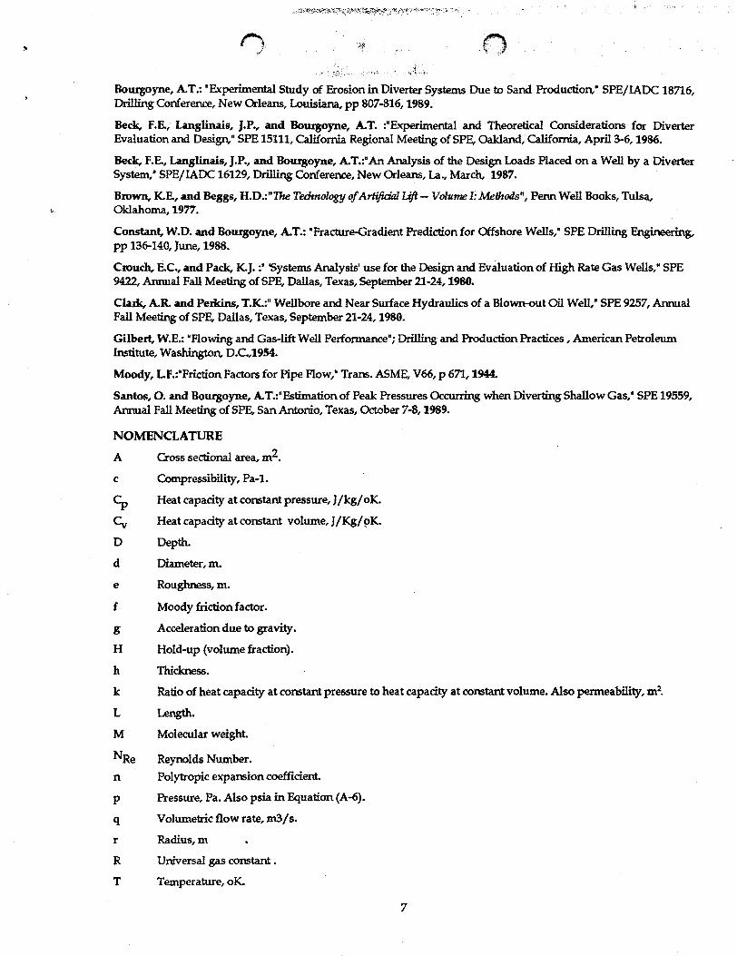
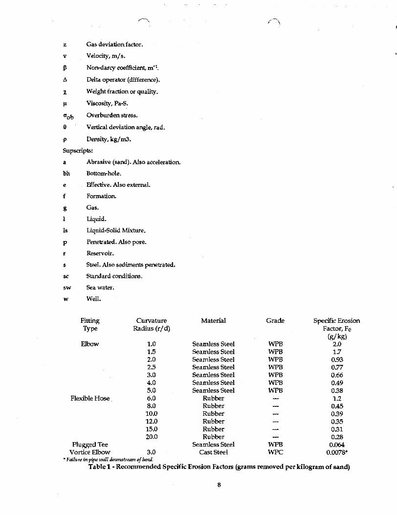
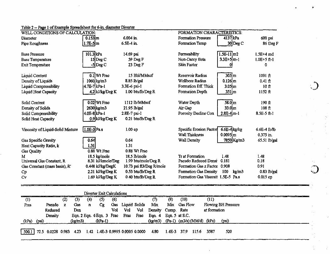
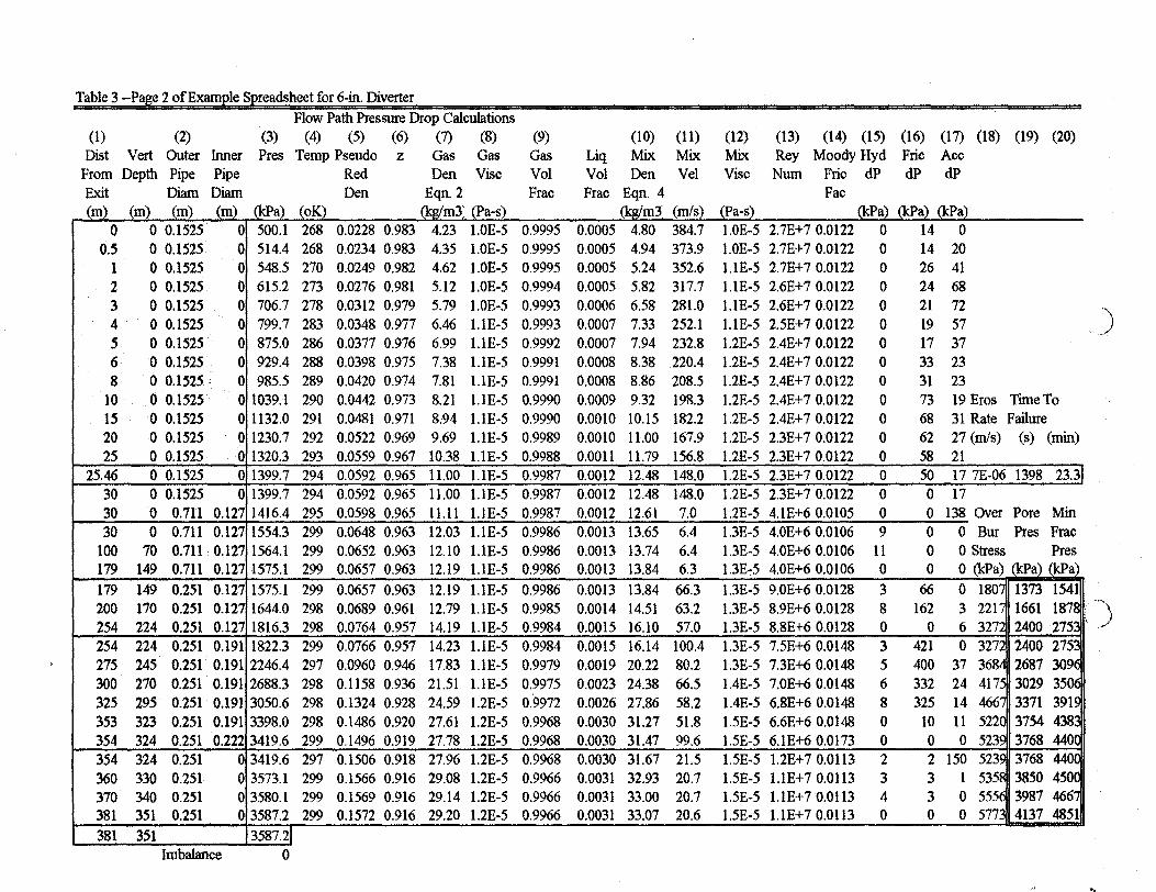
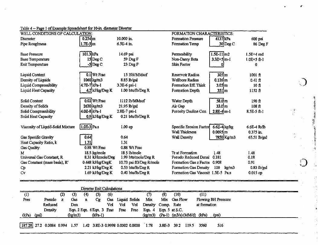