a review on anaerobic–aerobic treatment of industrial … · a review on anaerobic–aerobic...
TRANSCRIPT
R
A
YS
a
ARRA
KAIMI
1
toqedplc(irgtaamaii
1d
Chemical Engineering Journal 155 (2009) 1–18
Contents lists available at ScienceDirect
Chemical Engineering Journal
journa l homepage: www.e lsev ier .com/ locate /ce j
eview
review on anaerobic–aerobic treatment of industrial and municipal wastewater
i Jing Chan, Mei Fong Chong ∗, Chung Lim Law, D.G. Hassellchool of Chemical and Environmental Engineering, Faculty of Engineering, The University of Nottingham Malaysia Campus, Jalan Broga, 43500 Semenyih, Selangor, Malaysia
r t i c l e i n f o
rticle history:eceived 1 April 2009eceived in revised form 14 June 2009ccepted 16 June 2009
eywords:naerobic–aerobic treatment
ndustrial wastewaterunicipal wastewater
ntegrated anaerobic–aerobic bioreactors
a b s t r a c t
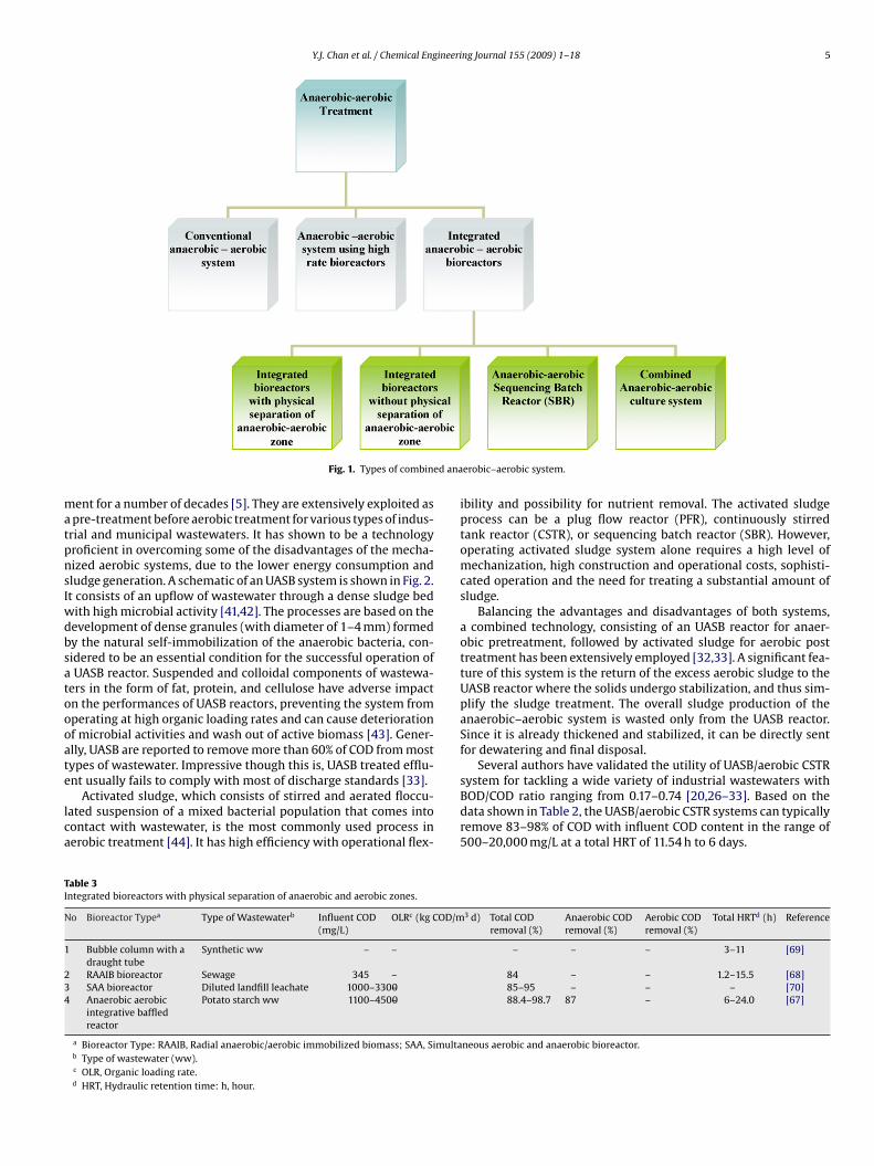
Anaerobic–aerobic systems have been remarkably employed in industrial and municipal wastewatertreatment for many years. While previously most treatment of wastewaters have been carried out inconventional anaerobic–aerobic treatment plants, in recent years, high rate anaerobic–aerobic biore-actors have been increasingly employed for wastewaters with high chemical oxygen demand (COD).This paper provides a review of the various types of high rate anaerobic–aerobic water treatment tech-niques currently available including high rate bioreactors and integrated anaerobic–aerobic bioreactors.The integrated bioreactors are classified into four types, which are (i) integrated bioreactors with phys-ical separation of anaerobic–aerobic zone, (ii) integrated bioreactors without physical separation ofanaerobic–aerobic zone, (iii) anaerobic–aerobic Sequencing Batch Reactors (SBR), and (iv) combined
anaerobic–aerobic culture system. The integration of aerobic and anaerobic degradation pathways ina single bioreactor is capable of enhancing the overall degradation efficiency. The merits of different inte-grated anaerobic–aerobic bioreactors are highlighted and comparison made to identify possible futureareas of research to fully utilize these methods of wastewater treatment. The comparison demonstratesthat using an integrated bioreactor with stacked configuration in treating high strength industrial wastew-e to m3%).
aters is advantageous duefficiencies (in excess of 8
. Introduction
Over the last century, continued population growth and indus-rialization have resulted in the degradation of various ecosystemsn which human life relies on. In the case of ocean and riveruality, such pollution is primarily caused by the discharge of inad-quately treated industrial and municipal wastewater. On initialischarge, these wastewaters can contain high levels of inorganicollutants which can be easily biodegradable, but whose impact
oad on the ecosystems, either in Total Suspended Solids (TSS), Bio-hemical Oxygen Demand (BOD5), or Chemical Oxygen DemandCOD), may be in the tens of thousands mg/L [1]. To combat thisncreasing burden on our aquatic environment, increasingly strictegulation on pollution discharge is being implemented by variousovernmental bodies, with focus primarily on waste reduction. Thereatment systems developed by industry are frequently regardeds a regulatory obligation, increasing capital and running costsnd yielding negative economic returns. Compliance to environ-
ental legislations should not necessary lead to the creation ofdditional costs, but can instead provide a secondary source ofncome. One possible source of increased revenue available tondustries is through taking advantage of the incentives awarded by
∗ Corresponding author. Tel.: +60 3 8924 8347; fax: +60 3 8924 8017.E-mail address: [email protected] (M.F. Chong).
385-8947/$ – see front matter © 2009 Elsevier B.V. All rights reserved.oi:10.1016/j.cej.2009.06.041
inimal space requirements, low capital cost and excellent COD removal
© 2009 Elsevier B.V. All rights reserved.
the Clean Development Mechanism (CDM) under the Kyoto Protocol1997.
In the treatment of wastewater, biological treatment appears tobe a promising technology to attain revenue from Certified Emis-sion Reduction (CER) credits, more commonly known as carboncredits from the CDM as methane gas is generated from anaerobicdigestion and can be utilized as renewable energy. With appro-priate analysis and environmental control, almost all wastewaterscontaining biodegradable constituents with a BOD/COD ratio of0.5 or greater can be treated easily by biological means [2]. Incomparison to other methods of wastewater treatment, it also hasthe advantages of lower treatment costs with no secondary pol-lution [3]. Both aerobic and anaerobic processes can be used; theformer involves the use of free or dissolved oxygen by microor-ganisms (aerobes) in the conversion of organic wastes to biomassand CO2 while in the latter complex organic wastes are degradedinto methane, CO2 and H2O through three basic steps (hydrolysis,acidogenesis including acetogenesis and methanogenesis) in theabsence of oxygen. Aerobic biological processes are commonly usedin the treatment of organic wastewaters for achieving high degreeof treatment efficiency, while in anaerobic treatment, considerable
progress has been achieved in anaerobic biotechnology for wastetreatment based on the concept of resource recovery and utilizationwhile still achieving the objective of pollution control [4,5].The various merits of both treatments are highlighted in Table 1,and both systems are capable of achieving high organic removal
2 Y.J. Chan et al. / Chemical Engineering Journal 155 (2009) 1–18
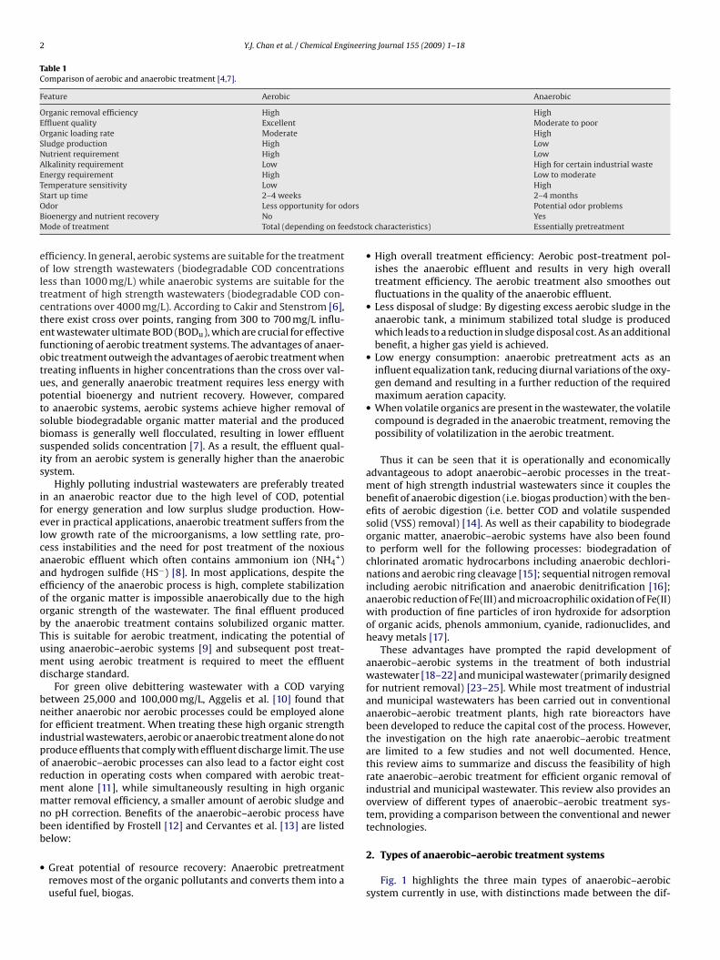
Table 1Comparison of aerobic and anaerobic treatment [4,7].
Feature Aerobic Anaerobic
Organic removal efficiency High HighEffluent quality Excellent Moderate to poorOrganic loading rate Moderate HighSludge production High LowNutrient requirement High LowAlkalinity requirement Low High for certain industrial wasteEnergy requirement High Low to moderateTemperature sensitivity Low HighSO orsBM edstoc
eoltctefotuptsbsis
ifelcaaeoobTumd
bnfipormmnbb
•
tart up time 2–4 weeksdor Less opportunity for odioenergy and nutrient recovery Noode of treatment Total (depending on fe
fficiency. In general, aerobic systems are suitable for the treatmentf low strength wastewaters (biodegradable COD concentrations
ess than 1000 mg/L) while anaerobic systems are suitable for thereatment of high strength wastewaters (biodegradable COD con-entrations over 4000 mg/L). According to Cakir and Stenstrom [6],here exist cross over points, ranging from 300 to 700 mg/L influ-nt wastewater ultimate BOD (BODu), which are crucial for effectiveunctioning of aerobic treatment systems. The advantages of anaer-bic treatment outweigh the advantages of aerobic treatment whenreating influents in higher concentrations than the cross over val-es, and generally anaerobic treatment requires less energy withotential bioenergy and nutrient recovery. However, comparedo anaerobic systems, aerobic systems achieve higher removal ofoluble biodegradable organic matter material and the producediomass is generally well flocculated, resulting in lower effluentuspended solids concentration [7]. As a result, the effluent qual-ty from an aerobic system is generally higher than the anaerobicystem.
Highly polluting industrial wastewaters are preferably treatedn an anaerobic reactor due to the high level of COD, potentialor energy generation and low surplus sludge production. How-ver in practical applications, anaerobic treatment suffers from theow growth rate of the microorganisms, a low settling rate, pro-ess instabilities and the need for post treatment of the noxiousnaerobic effluent which often contains ammonium ion (NH4
+)nd hydrogen sulfide (HS−) [8]. In most applications, despite thefficiency of the anaerobic process is high, complete stabilizationf the organic matter is impossible anaerobically due to the highrganic strength of the wastewater. The final effluent producedy the anaerobic treatment contains solubilized organic matter.his is suitable for aerobic treatment, indicating the potential ofsing anaerobic–aerobic systems [9] and subsequent post treat-ent using aerobic treatment is required to meet the effluent
ischarge standard.For green olive debittering wastewater with a COD varying
etween 25,000 and 100,000 mg/L, Aggelis et al. [10] found thateither anaerobic nor aerobic processes could be employed alone
or efficient treatment. When treating these high organic strengthndustrial wastewaters, aerobic or anaerobic treatment alone do notroduce effluents that comply with effluent discharge limit. The usef anaerobic–aerobic processes can also lead to a factor eight costeduction in operating costs when compared with aerobic treat-
ent alone [11], while simultaneously resulting in high organicatter removal efficiency, a smaller amount of aerobic sludge and
o pH correction. Benefits of the anaerobic–aerobic process haveeen identified by Frostell [12] and Cervantes et al. [13] are listed
elow:Great potential of resource recovery: Anaerobic pretreatmentremoves most of the organic pollutants and converts them into auseful fuel, biogas.
2–4 monthsPotential odor problemsYes
k characteristics) Essentially pretreatment
• High overall treatment efficiency: Aerobic post-treatment pol-ishes the anaerobic effluent and results in very high overalltreatment efficiency. The aerobic treatment also smoothes outfluctuations in the quality of the anaerobic effluent.
• Less disposal of sludge: By digesting excess aerobic sludge in theanaerobic tank, a minimum stabilized total sludge is producedwhich leads to a reduction in sludge disposal cost. As an additionalbenefit, a higher gas yield is achieved.
• Low energy consumption: anaerobic pretreatment acts as aninfluent equalization tank, reducing diurnal variations of the oxy-gen demand and resulting in a further reduction of the requiredmaximum aeration capacity.
• When volatile organics are present in the wastewater, the volatilecompound is degraded in the anaerobic treatment, removing thepossibility of volatilization in the aerobic treatment.
Thus it can be seen that it is operationally and economicallyadvantageous to adopt anaerobic–aerobic processes in the treat-ment of high strength industrial wastewaters since it couples thebenefit of anaerobic digestion (i.e. biogas production) with the ben-efits of aerobic digestion (i.e. better COD and volatile suspendedsolid (VSS) removal) [14]. As well as their capability to biodegradeorganic matter, anaerobic–aerobic systems have also been foundto perform well for the following processes: biodegradation ofchlorinated aromatic hydrocarbons including anaerobic dechlori-nations and aerobic ring cleavage [15]; sequential nitrogen removalincluding aerobic nitrification and anaerobic denitrification [16];anaerobic reduction of Fe(III) and microacrophilic oxidation of Fe(II)with production of fine particles of iron hydroxide for adsorptionof organic acids, phenols ammonium, cyanide, radionuclides, andheavy metals [17].
These advantages have prompted the rapid development ofanaerobic–aerobic systems in the treatment of both industrialwastewater [18–22] and municipal wastewater (primarily designedfor nutrient removal) [23–25]. While most treatment of industrialand municipal wastewaters has been carried out in conventionalanaerobic–aerobic treatment plants, high rate bioreactors havebeen developed to reduce the capital cost of the process. However,the investigation on the high rate anaerobic–aerobic treatmentare limited to a few studies and not well documented. Hence,this review aims to summarize and discuss the feasibility of highrate anaerobic–aerobic treatment for efficient organic removal ofindustrial and municipal wastewater. This review also provides anoverview of different types of anaerobic–aerobic treatment sys-tem, providing a comparison between the conventional and newertechnologies.
2. Types of anaerobic–aerobic treatment systems
Fig. 1 highlights the three main types of anaerobic–aerobicsystem currently in use, with distinctions made between the dif-
Y.J.Chanet
al./ChemicalEngineering
Journal155 (2009) 1–183
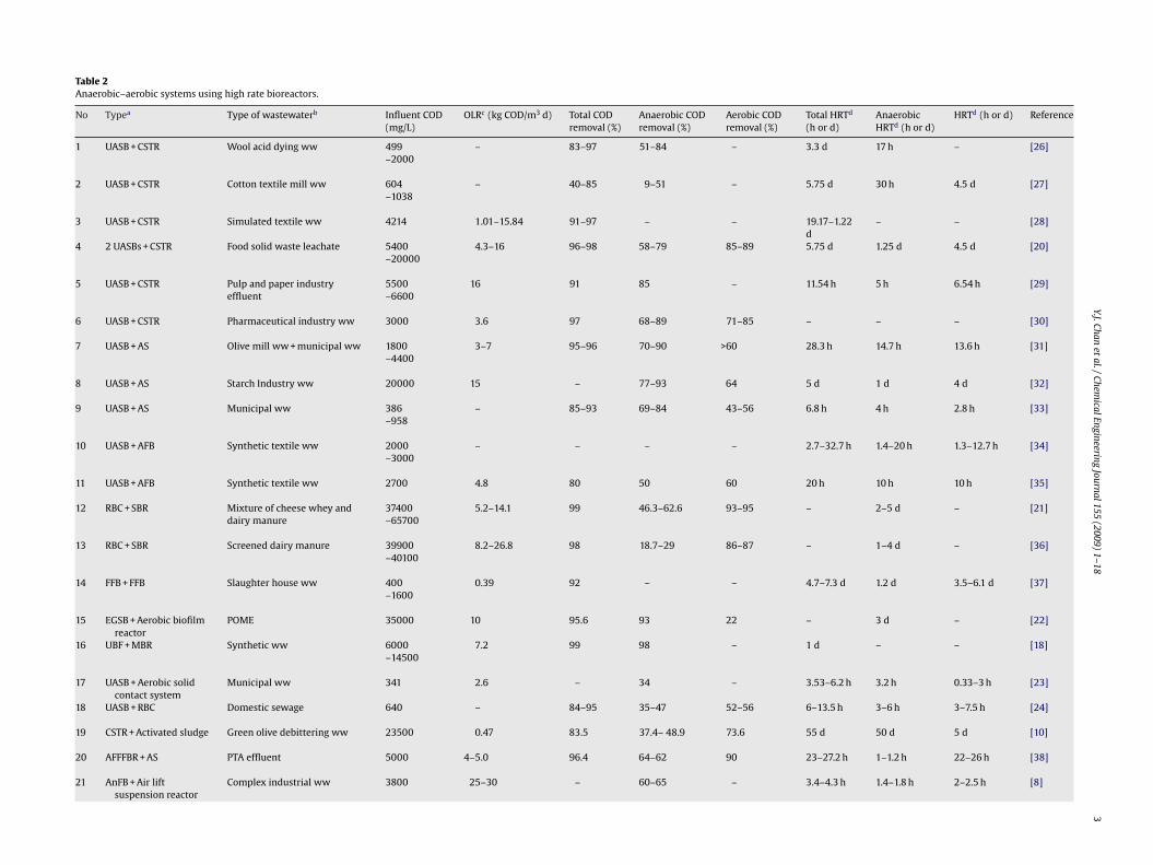
Table 2Anaerobic–aerobic systems using high rate bioreactors.
No Typea Type of wastewaterb Influent COD(mg/L)
OLRc (kg COD/m3 d) Total CODremoval (%)
Anaerobic CODremoval (%)
Aerobic CODremoval (%)
Total HRTd
(h or d)AnaerobicHRTd (h or d)
HRTd (h or d) Reference
1 UASB + CSTR Wool acid dying ww 499–2000
– 83–97 51–84 – 3.3 d 17 h – [26]
2 UASB + CSTR Cotton textile mill ww 604–1038
– 40–85 9–51 – 5.75 d 30 h 4.5 d [27]
3 UASB + CSTR Simulated textile ww 4214 1.01–15.84 91–97 – – 19.17–1.22d
– – [28]
4 2 UASBs + CSTR Food solid waste leachate 5400–20000
4.3–16 96–98 58–79 85–89 5.75 d 1.25 d 4.5 d [20]
5 UASB + CSTR Pulp and paper industryeffluent
5500–6600
16 91 85 – 11.54 h 5 h 6.54 h [29]
6 UASB + CSTR Pharmaceutical industry ww 3000 3.6 97 68–89 71–85 – – – [30]
7 UASB + AS Olive mill ww + municipal ww 1800–4400
3–7 95–96 70–90 >60 28.3 h 14.7 h 13.6 h [31]
8 UASB + AS Starch Industry ww 20000 15 – 77–93 64 5 d 1 d 4 d [32]
9 UASB + AS Municipal ww 386–958
– 85–93 69–84 43–56 6.8 h 4 h 2.8 h [33]
10 UASB + AFB Synthetic textile ww 2000–3000
– – – – 2.7–32.7 h 1.4–20 h 1.3–12.7 h [34]
11 UASB + AFB Synthetic textile ww 2700 4.8 80 50 60 20 h 10 h 10 h [35]
12 RBC + SBR Mixture of cheese whey anddairy manure
37400–65700
5.2–14.1 99 46.3–62.6 93–95 – 2–5 d – [21]
13 RBC + SBR Screened dairy manure 39900–40100
8.2–26.8 98 18.7–29 86–87 – 1–4 d – [36]
14 FFB + FFB Slaughter house ww 400–1600
0.39 92 – – 4.7–7.3 d 1.2 d 3.5–6.1 d [37]
15 EGSB + Aerobic biofilmreactor
POME 35000 10 95.6 93 22 – 3 d – [22]
16 UBF + MBR Synthetic ww 6000–14500
7.2 99 98 – 1 d – – [18]
17 UASB + Aerobic solidcontact system
Municipal ww 341 2.6 – 34 – 3.53–6.2 h 3.2 h 0.33–3 h [23]
18 UASB + RBC Domestic sewage 640 – 84–95 35–47 52–56 6–13.5 h 3–6 h 3–7.5 h [24]
19 CSTR + Activated sludge Green olive debittering ww 23500 0.47 83.5 37.4– 48.9 73.6 55 d 50 d 5 d [10]
20 AFFFBR + AS PTA effluent 5000 4–5.0 96.4 64–62 90 23–27.2 h 1–1.2 h 22–26 h [38]
21 AnFB + Air liftsuspension reactor
Complex industrial ww 3800 25–30 – 60–65 – 3.4–4.3 h 1.4–1.8 h 2–2.5 h [8]
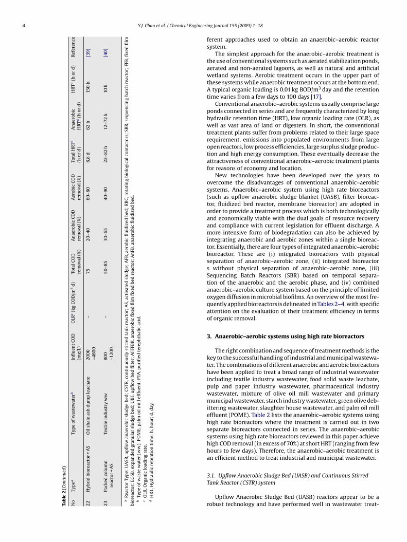
4 Y.J. Chan et al. / Chemical Engineeri
Tab
le2
(Con
tinu
ed)
No
Typ
eaTy
pe
ofw
aste
wat
erb
Infl
uen
tCO
D(m
g/L)
OLR
c(k
gCO
D/m
3d)
Tota
lCO
Dre
mov
al(%
)A
nae
robi
cCO
Dre
mov
al(%
)A
erob
icCO
Dre
mov
al(%
)To
talH
RTd
(hor
d)
An
aero
bic
HR
Td(h
ord
)H
RTd
(hor
d)
Ref
eren
ce
22H
ybri
dbi
orea
ctor
+A
SO
ilsh
ale
ash
du
mp
leac
hat
e20
00
–460
0–
7520
–40
60–8
08.
8d
62h
150
h[3
9]
23Pa
cked
colu
mn
reac
tor+
AS
Text
ile
ind
ust
ryw
w80
0–1
200
–50
–85
30–6
540
–90
22–8
2h
12–7
2h
10h
[40]
aR
eact
orTy
pe:
UA
SB,u
pfl
owan
aero
bic
slu
dge
bed
;C
STR
,con
tin
uou
sly
stir
red
tan
kre
acto
r;A
S,ac
tiva
ted
slu
dge
;A
FB,a
erob
icfl
uid
ized
bed
;R
BC
,rot
atin
gbi
olog
ical
con
tact
ors;
SBR
,seq
uen
cin
gba
tch
reac
tor;
FFB
,fixe
dfi
lmbi
orea
ctor
;EG
SB,e
xpan
ded
gran
ula
rsl
ud
gebe
d;
UB
F,u
pfl
owbe
dfi
lter
;A
FFFB
R,a
nae
robi
cfi
xed
film
fixe
dbe
dre
acto
r;A
nFB
,an
aero
bic
flu
idiz
edbe
d.
bTy
pe
ofw
aste
wat
er(w
w):
POM
E,p
alm
oilm
ille
fflu
ent;
PTA
,pu
rifi
edte
rep
hth
alic
acid
.c
OLR
,Org
anic
load
ing
rate
.d
HR
T,H
ydra
uli
cre
ten
tion
tim
e:h
,hou
r;d
,day
.
ng Journal 155 (2009) 1–18
ferent approaches used to obtain an anaerobic–aerobic reactorsystem.
The simplest approach for the anaerobic–aerobic treatment isthe use of conventional systems such as aerated stabilization ponds,aerated and non-aerated lagoons, as well as natural and artificialwetland systems. Aerobic treatment occurs in the upper part ofthese systems while anaerobic treatment occurs at the bottom end.A typical organic loading is 0.01 kg BOD/m3 day and the retentiontime varies from a few days to 100 days [17].
Conventional anaerobic–aerobic systems usually comprise largeponds connected in series and are frequently characterized by longhydraulic retention time (HRT), low organic loading rate (OLR), aswell as vast area of land or digesters. In short, the conventionaltreatment plants suffer from problems related to their large spacerequirement, emissions into populated environments from largeopen reactors, low process efficiencies, large surplus sludge produc-tion and high energy consumption. These eventually decrease theattractiveness of conventional anaerobic–aerobic treatment plantsfor reasons of economy and location.
New technologies have been developed over the years toovercome the disadvantages of conventional anaerobic–aerobicsystems. Anaerobic–aerobic system using high rate bioreactors(such as upflow anaerobic sludge blanket (UASB), filter bioreac-tor, fluidized bed reactor, membrane bioreactor) are adopted inorder to provide a treatment process which is both technologicallyand economically viable with the dual goals of resource recoveryand compliance with current legislation for effluent discharge. Amore intensive form of biodegradation can also be achieved byintegrating anaerobic and aerobic zones within a single bioreac-tor. Essentially, there are four types of integrated anaerobic–aerobicbioreactor. These are (i) integrated bioreactors with physicalseparation of anaerobic–aerobic zone, (ii) integrated bioreactors without physical separation of anaerobic–aerobic zone, (iii)Sequencing Batch Reactors (SBR) based on temporal separa-tion of the anaerobic and the aerobic phase, and (iv) combinedanaerobic–aerobic culture system based on the principle of limitedoxygen diffusion in microbial biofilms. An overview of the most fre-quently applied bioreactors is delineated in Tables 2–4, with specificattention on the evaluation of their treatment efficiency in termsof organic removal.
3. Anaerobic–aerobic systems using high rate bioreactors
The right combination and sequence of treatment methods is thekey to the successful handling of industrial and municipal wastewa-ter. The combinations of different anaerobic and aerobic bioreactorshave been applied to treat a broad range of industrial wastewaterincluding textile industry wastewater, food solid waste leachate,pulp and paper industry wastewater, pharmaceutical industrywastewater, mixture of olive oil mill wastewater and primarymunicipal wastewater, starch industry wastewater, green olive deb-ittering wastewater, slaughter house wastewater, and palm oil milleffluent (POME). Table 2 lists the anaerobic–aerobic systems usinghigh rate bioreactors where the treatment is carried out in twoseparate bioreactors connected in series. The anaerobic–aerobicsystems using high rate bioreactors reviewed in this paper achievehigh COD removal (in excess of 70%) at short HRT (ranging from fewhours to few days). Therefore, the anaerobic–aerobic treatment isan efficient method to treat industrial and municipal wastewater.
3.1. Upflow Anaerobic Sludge Bed (UASB) and Continuous StirredTank Reactor (CSTR) system
Upflow Anaerobic Sludge Bed (UASB) reactors appear to be arobust technology and have performed well in wastewater treat-
Y.J. Chan et al. / Chemical Engineering Journal 155 (2009) 1–18 5
d ana
matpnsIwdbsatoooate
lca
TI
N
1
234
Fig. 1. Types of combine
ent for a number of decades [5]. They are extensively exploited aspre-treatment before aerobic treatment for various types of indus-
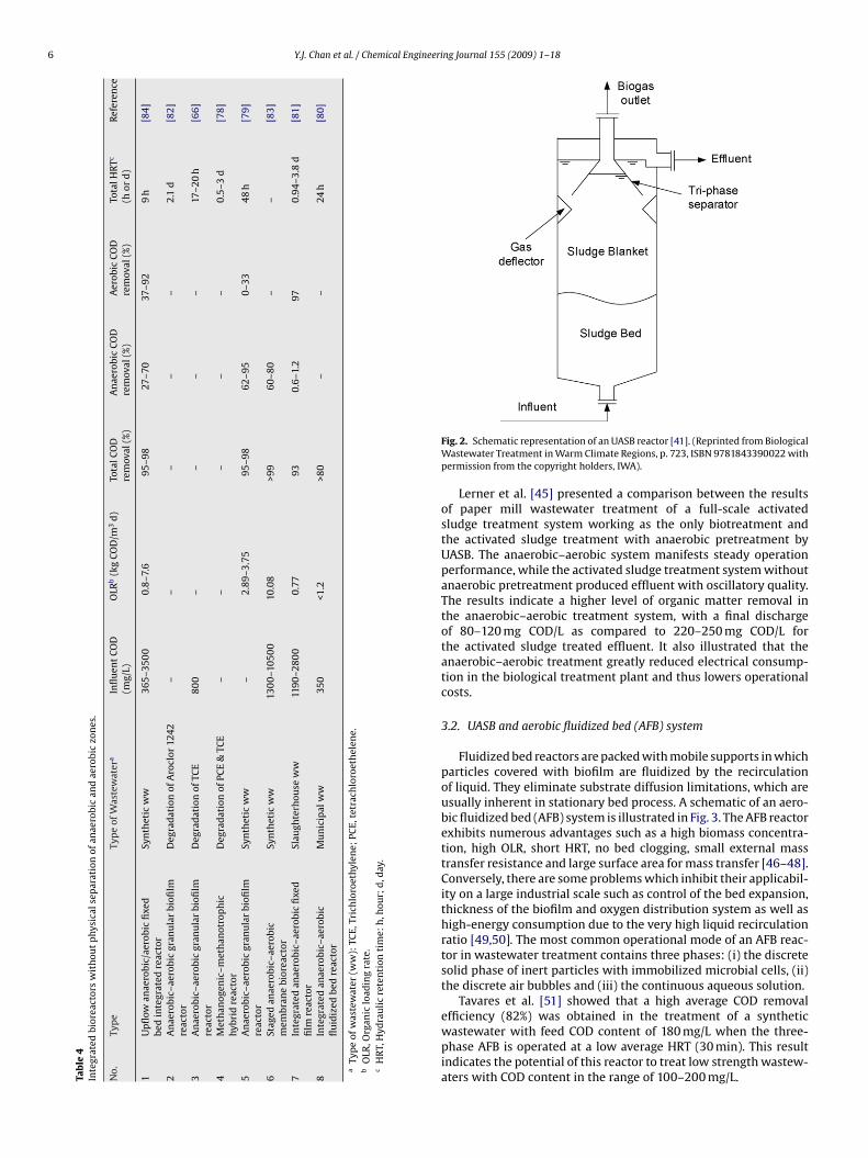
rial and municipal wastewaters. It has shown to be a technologyroficient in overcoming some of the disadvantages of the mecha-ized aerobic systems, due to the lower energy consumption andludge generation. A schematic of an UASB system is shown in Fig. 2.t consists of an upflow of wastewater through a dense sludge bed
ith high microbial activity [41,42]. The processes are based on theevelopment of dense granules (with diameter of 1–4 mm) formedy the natural self-immobilization of the anaerobic bacteria, con-idered to be an essential condition for the successful operation ofUASB reactor. Suspended and colloidal components of wastewa-
ers in the form of fat, protein, and cellulose have adverse impactn the performances of UASB reactors, preventing the system fromperating at high organic loading rates and can cause deteriorationf microbial activities and wash out of active biomass [43]. Gener-lly, UASB are reported to remove more than 60% of COD from mostypes of wastewater. Impressive though this is, UASB treated efflu-nt usually fails to comply with most of discharge standards [33].
Activated sludge, which consists of stirred and aerated floccu-ated suspension of a mixed bacterial population that comes intoontact with wastewater, is the most commonly used process inerobic treatment [44]. It has high efficiency with operational flex-
able 3ntegrated bioreactors with physical separation of anaerobic and aerobic zones.
o Bioreactor Typea Type of Wastewaterb Influent COD(mg/L)
OLRc (kg COD/m
Bubble column with adraught tube
Synthetic ww – –
RAAIB bioreactor Sewage 345 –SAA bioreactor Diluted landfill leachate 1000–3300–Anaerobic aerobicintegrative baffledreactor
Potato starch ww 1100–4500–
a Bioreactor Type: RAAIB, Radial anaerobic/aerobic immobilized biomass; SAA, Simultab Type of wastewater (ww).c OLR, Organic loading rate.d HRT, Hydraulic retention time: h, hour.
erobic–aerobic system.
ibility and possibility for nutrient removal. The activated sludgeprocess can be a plug flow reactor (PFR), continuously stirredtank reactor (CSTR), or sequencing batch reactor (SBR). However,operating activated sludge system alone requires a high level ofmechanization, high construction and operational costs, sophisti-cated operation and the need for treating a substantial amount ofsludge.
Balancing the advantages and disadvantages of both systems,a combined technology, consisting of an UASB reactor for anaer-obic pretreatment, followed by activated sludge for aerobic posttreatment has been extensively employed [32,33]. A significant fea-ture of this system is the return of the excess aerobic sludge to theUASB reactor where the solids undergo stabilization, and thus sim-plify the sludge treatment. The overall sludge production of theanaerobic–aerobic system is wasted only from the UASB reactor.Since it is already thickened and stabilized, it can be directly sentfor dewatering and final disposal.
Several authors have validated the utility of UASB/aerobic CSTRsystem for tackling a wide variety of industrial wastewaters with
BOD/COD ratio ranging from 0.17–0.74 [20,26–33]. Based on thedata shown in Table 2, the UASB/aerobic CSTR systems can typicallyremove 83–98% of COD with influent COD content in the range of500–20,000 mg/L at a total HRT of 11.54 h to 6 days.3 d) Total CODremoval (%)
Anaerobic CODremoval (%)
Aerobic CODremoval (%)
Total HRTd (h) Reference
– – – 3–11 [69]
84 – – 1.2–15.5 [68]85–95 – – – [70]88.4–98.7 87 – 6–24.0 [67]
neous aerobic and anaerobic bioreactor.
6 Y.J. Chan et al. / Chemical Engineering Journal 155 (2009) 1–18
Tab
le4
Inte
grat
edbi
orea
ctor
sw
ith
out
phy
sica
lsep
arat
ion
ofan
aero
bic
and
aero
bic
zon
es.
No.
Typ
eTy
pe
ofW
aste
wat
era
Infl
uen
tCO
D(m
g/L)
OLR
b(k
gCO
D/m
3d)
Tota
lCO
Dre
mov
al(%
)A
nae
robi
cCO
Dre
mov
al(%
)A
erob
icCO
Dre
mov
al(%
)To
talH
RTc
(hor
d)
Ref
eren
ce
1U
pfl
owan
aero
bic/
aero
bic
fixe
dbe
din
tegr
ated
reac
tor
Syn
thet
icw
w36
5–35
00
0.8–
7.6
95–9
827
–70
37–9
29
h[8
4]
2A
nae
robi
c–ae
robi
cgr
anu
lar
biofi
lmre
acto
rD
egra
dat
ion
ofA
rocl
or12
42–
––
––
2.1
d[8
2]
3A
nae
robi
c–ae
robi
cgr
anu
lar
biofi
lmre
acto
rD
egra
dat
ion
ofTC
E80
0–
––
–17
–20
h[6
6]
4M
eth
anog
enic
–met
han
otro
ph
ichy
brid
reac
tor
Deg
rad
atio
nof
PCE
&TC
E–
––
––
0.5–
3d
[78]
5A
nae
robi
c–ae
robi
cgr
anu
lar
biofi
lmre
acto
rSy
nth
etic
ww
–2.
89–3
.75
95–9
862
–95
0–33
48
h[7
9]
6St
aged
anae
robi
c–ae
robi
cm
embr
ane
bior
eact
orSy
nth
etic
ww
130
0–10
500
10.0
8>9
960
–80
––
[83]
7In
tegr
ated
anae
robi
c–ae
robi
cfi
xed
film
reac
tor
Slau
ghte
rhou
sew
w11
90–2
800
0.77
930.
6–1.
297
0.94
–3.8
d[8
1]
8In
tegr
ated
anae
robi
c–ae
robi
cfl
uid
ized
bed
reac
tor
Mu
nic
ipal
ww
350
<1.2
>80
––
24h
[80]
aTy
pe
ofw
aste
wat
er(w
w):
TCE,
Tric
hlo
roet
hyle
ne;
PCE,
tetr
ach
loro
eth
elen
e.b
OLR
,Org
anic
load
ing
rate
.c
HR
T,H
ydra
uli
cre
ten
tion
tim
e:h
,hou
r;d
,day
.
Fig. 2. Schematic representation of an UASB reactor [41]. (Reprinted from BiologicalWastewater Treatment in Warm Climate Regions, p. 723, ISBN 9781843390022 withpermission from the copyright holders, IWA).
Lerner et al. [45] presented a comparison between the resultsof paper mill wastewater treatment of a full-scale activatedsludge treatment system working as the only biotreatment andthe activated sludge treatment with anaerobic pretreatment byUASB. The anaerobic–aerobic system manifests steady operationperformance, while the activated sludge treatment system withoutanaerobic pretreatment produced effluent with oscillatory quality.The results indicate a higher level of organic matter removal inthe anaerobic–aerobic treatment system, with a final dischargeof 80–120 mg COD/L as compared to 220–250 mg COD/L forthe activated sludge treated effluent. It also illustrated that theanaerobic–aerobic treatment greatly reduced electrical consump-tion in the biological treatment plant and thus lowers operationalcosts.
3.2. UASB and aerobic fluidized bed (AFB) system
Fluidized bed reactors are packed with mobile supports in whichparticles covered with biofilm are fluidized by the recirculationof liquid. They eliminate substrate diffusion limitations, which areusually inherent in stationary bed process. A schematic of an aero-bic fluidized bed (AFB) system is illustrated in Fig. 3. The AFB reactorexhibits numerous advantages such as a high biomass concentra-tion, high OLR, short HRT, no bed clogging, small external masstransfer resistance and large surface area for mass transfer [46–48].Conversely, there are some problems which inhibit their applicabil-ity on a large industrial scale such as control of the bed expansion,thickness of the biofilm and oxygen distribution system as well ashigh-energy consumption due to the very high liquid recirculationratio [49,50]. The most common operational mode of an AFB reac-tor in wastewater treatment contains three phases: (i) the discretesolid phase of inert particles with immobilized microbial cells, (ii)the discrete air bubbles and (iii) the continuous aqueous solution.
Tavares et al. [51] showed that a high average COD removal
efficiency (82%) was obtained in the treatment of a syntheticwastewater with feed COD content of 180 mg/L when the three-phase AFB is operated at a low average HRT (30 min). This resultindicates the potential of this reactor to treat low strength wastew-aters with COD content in the range of 100–200 mg/L.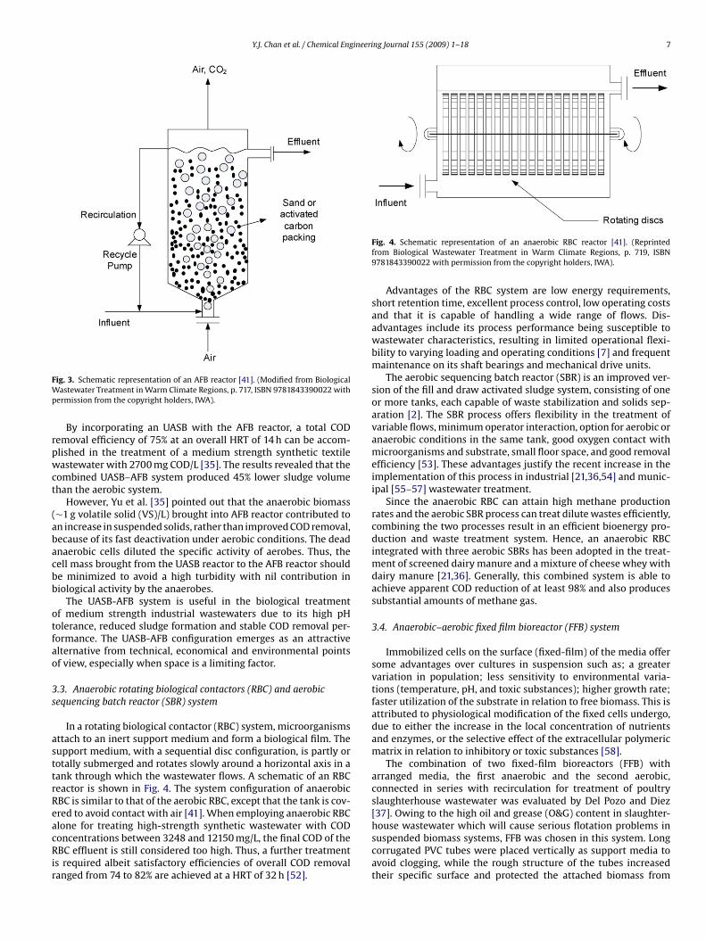
Y.J. Chan et al. / Chemical Engineering Journal 155 (2009) 1–18 7
FWp
rpwct
(abacbb
otfao
3s
asttrReacRir
ig. 3. Schematic representation of an AFB reactor [41]. (Modified from Biologicalastewater Treatment in Warm Climate Regions, p. 717, ISBN 9781843390022 with
ermission from the copyright holders, IWA).
By incorporating an UASB with the AFB reactor, a total CODemoval efficiency of 75% at an overall HRT of 14 h can be accom-lished in the treatment of a medium strength synthetic textileastewater with 2700 mg COD/L [35]. The results revealed that the
ombined UASB–AFB system produced 45% lower sludge volumehan the aerobic system.
However, Yu et al. [35] pointed out that the anaerobic biomass∼1 g volatile solid (VS)/L) brought into AFB reactor contributed ton increase in suspended solids, rather than improved COD removal,ecause of its fast deactivation under aerobic conditions. The deadnaerobic cells diluted the specific activity of aerobes. Thus, theell mass brought from the UASB reactor to the AFB reactor shoulde minimized to avoid a high turbidity with nil contribution iniological activity by the anaerobes.
The UASB-AFB system is useful in the biological treatmentf medium strength industrial wastewaters due to its high pHolerance, reduced sludge formation and stable COD removal per-ormance. The UASB-AFB configuration emerges as an attractivelternative from technical, economical and environmental pointsf view, especially when space is a limiting factor.
.3. Anaerobic rotating biological contactors (RBC) and aerobicequencing batch reactor (SBR) system
In a rotating biological contactor (RBC) system, microorganismsttach to an inert support medium and form a biological film. Theupport medium, with a sequential disc configuration, is partly orotally submerged and rotates slowly around a horizontal axis in aank through which the wastewater flows. A schematic of an RBCeactor is shown in Fig. 4. The system configuration of anaerobicBC is similar to that of the aerobic RBC, except that the tank is cov-red to avoid contact with air [41]. When employing anaerobic RBC
lone for treating high-strength synthetic wastewater with CODoncentrations between 3248 and 12150 mg/L, the final COD of theBC effluent is still considered too high. Thus, a further treatments required albeit satisfactory efficiencies of overall COD removalanged from 74 to 82% are achieved at a HRT of 32 h [52].
Fig. 4. Schematic representation of an anaerobic RBC reactor [41]. (Reprintedfrom Biological Wastewater Treatment in Warm Climate Regions, p. 719, ISBN9781843390022 with permission from the copyright holders, IWA).
Advantages of the RBC system are low energy requirements,short retention time, excellent process control, low operating costsand that it is capable of handling a wide range of flows. Dis-advantages include its process performance being susceptible towastewater characteristics, resulting in limited operational flexi-bility to varying loading and operating conditions [7] and frequentmaintenance on its shaft bearings and mechanical drive units.
The aerobic sequencing batch reactor (SBR) is an improved ver-sion of the fill and draw activated sludge system, consisting of oneor more tanks, each capable of waste stabilization and solids sep-aration [2]. The SBR process offers flexibility in the treatment ofvariable flows, minimum operator interaction, option for aerobic oranaerobic conditions in the same tank, good oxygen contact withmicroorganisms and substrate, small floor space, and good removalefficiency [53]. These advantages justify the recent increase in theimplementation of this process in industrial [21,36,54] and munic-ipal [55–57] wastewater treatment.
Since the anaerobic RBC can attain high methane productionrates and the aerobic SBR process can treat dilute wastes efficiently,combining the two processes result in an efficient bioenergy pro-duction and waste treatment system. Hence, an anaerobic RBCintegrated with three aerobic SBRs has been adopted in the treat-ment of screened dairy manure and a mixture of cheese whey withdairy manure [21,36]. Generally, this combined system is able toachieve apparent COD reduction of at least 98% and also producessubstantial amounts of methane gas.
3.4. Anaerobic–aerobic fixed film bioreactor (FFB) system
Immobilized cells on the surface (fixed-film) of the media offersome advantages over cultures in suspension such as; a greatervariation in population; less sensitivity to environmental varia-tions (temperature, pH, and toxic substances); higher growth rate;faster utilization of the substrate in relation to free biomass. This isattributed to physiological modification of the fixed cells undergo,due to either the increase in the local concentration of nutrientsand enzymes, or the selective effect of the extracellular polymericmatrix in relation to inhibitory or toxic substances [58].
The combination of two fixed-film bioreactors (FFB) witharranged media, the first anaerobic and the second aerobic,connected in series with recirculation for treatment of poultryslaughterhouse wastewater was evaluated by Del Pozo and Diez[37]. Owing to the high oil and grease (O&G) content in slaughter-
house wastewater which will cause serious flotation problems insuspended biomass systems, FFB was chosen in this system. Longcorrugated PVC tubes were placed vertically as support media toavoid clogging, while the rough structure of the tubes increasedtheir specific surface and protected the attached biomass from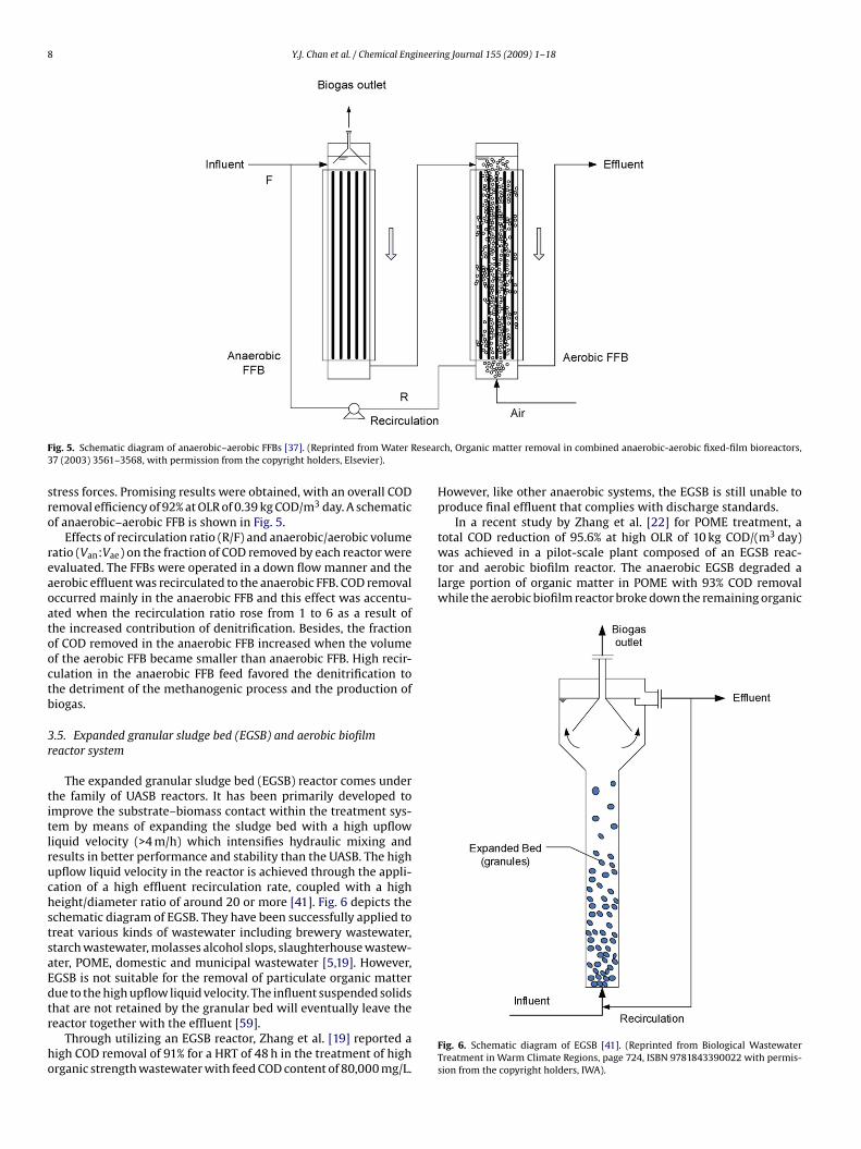
8 Y.J. Chan et al. / Chemical Engineering Journal 155 (2009) 1–18
F esear3
sro
reaoatooctb
3r
titlruchstsaEdtr
ho
was achieved in a pilot-scale plant composed of an EGSB reac-tor and aerobic biofilm reactor. The anaerobic EGSB degraded alarge portion of organic matter in POME with 93% COD removalwhile the aerobic biofilm reactor broke down the remaining organic
ig. 5. Schematic diagram of anaerobic–aerobic FFBs [37]. (Reprinted from Water R7 (2003) 3561–3568, with permission from the copyright holders, Elsevier).
tress forces. Promising results were obtained, with an overall CODemoval efficiency of 92% at OLR of 0.39 kg COD/m3 day. A schematicf anaerobic–aerobic FFB is shown in Fig. 5.
Effects of recirculation ratio (R/F) and anaerobic/aerobic volumeatio (Van:Vae) on the fraction of COD removed by each reactor werevaluated. The FFBs were operated in a down flow manner and theerobic effluent was recirculated to the anaerobic FFB. COD removalccurred mainly in the anaerobic FFB and this effect was accentu-ted when the recirculation ratio rose from 1 to 6 as a result ofhe increased contribution of denitrification. Besides, the fractionf COD removed in the anaerobic FFB increased when the volumef the aerobic FFB became smaller than anaerobic FFB. High recir-ulation in the anaerobic FFB feed favored the denitrification tohe detriment of the methanogenic process and the production ofiogas.
.5. Expanded granular sludge bed (EGSB) and aerobic biofilmeactor system
The expanded granular sludge bed (EGSB) reactor comes underhe family of UASB reactors. It has been primarily developed tomprove the substrate–biomass contact within the treatment sys-em by means of expanding the sludge bed with a high upflowiquid velocity (>4 m/h) which intensifies hydraulic mixing andesults in better performance and stability than the UASB. The highpflow liquid velocity in the reactor is achieved through the appli-ation of a high effluent recirculation rate, coupled with a higheight/diameter ratio of around 20 or more [41]. Fig. 6 depicts thechematic diagram of EGSB. They have been successfully applied toreat various kinds of wastewater including brewery wastewater,tarch wastewater, molasses alcohol slops, slaughterhouse wastew-ter, POME, domestic and municipal wastewater [5,19]. However,GSB is not suitable for the removal of particulate organic matterue to the high upflow liquid velocity. The influent suspended solids
hat are not retained by the granular bed will eventually leave theeactor together with the effluent [59].Through utilizing an EGSB reactor, Zhang et al. [19] reported aigh COD removal of 91% for a HRT of 48 h in the treatment of highrganic strength wastewater with feed COD content of 80,000 mg/L.
ch, Organic matter removal in combined anaerobic-aerobic fixed-film bioreactors,
However, like other anaerobic systems, the EGSB is still unable toproduce final effluent that complies with discharge standards.
In a recent study by Zhang et al. [22] for POME treatment, atotal COD reduction of 95.6% at high OLR of 10 kg COD/(m3 day)
Fig. 6. Schematic diagram of EGSB [41]. (Reprinted from Biological WastewaterTreatment in Warm Climate Regions, page 724, ISBN 9781843390022 with permis-sion from the copyright holders, IWA).
Y.J. Chan et al. / Chemical Engineeri
Fnaw
mrwtP
3b
wUtUec
fiapamMifpmasWifi
trMonbM
ig. 7. Schematic diagram of UBF-aerobic MBR system [18]. (Reprinted from Desali-ation, Simultaneous high-strength organic and nitrogen removal with combinednaerobic upflow bed filter and aerobic membrane bioreactor, 202 (2007) 114–121,ith permission from the copyright holders, Elsevier).
atter (22% of COD removal). In this case the reported averageate of organic matter transformed into methane in the EGSBas only 43% (based on the data of biogas measured), although
his could be attributed to the high suspended solids and oil inOME.
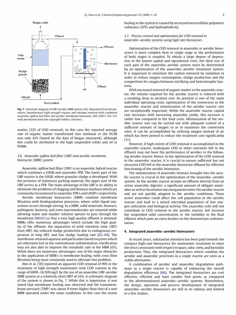
.6. Anaerobic upflow bed filter (UBF) and aerobic membraneioreactor (MBR) system
Anaerobic upflow bed filter (UBF) is an anaerobic hybrid reactorhich combines a UASB and anaerobic FFB. The lower part of theBF reactor is the UASB, where granular sludge is developed. With
he presence of stationary packing material, the upper part of theBF serves as a FFB. The main advantage of the UBF is its ability toliminate the problems of clogging and biomass washout which areommonly encountered in anaerobic FFB’s and UASB’s respectively.
Aerobic membrane bioreactors (MBR) combine membraneltration with biodegradation processes, where solid–liquid sep-ration occurs through sieving. In a MBR, solid materials, biomass,athogenic bacteria, and even macromolecules are retained whilellowing water and smaller solution species to pass through theembrane [60,61] so that a very high quality effluent is attained.BRs offer numerous advantages which include the high qual-
ty of the effluent, the separation of solid retention time (SRT)rom HRT, the reduced sludge production due to endogenous res-iration in long SRT, and low sludge loading rate [62–64]. Theembrane-retained aqueous and particulate based enzymes which
re otherwise lost in the conventional sedimentation–clarificationtep are also able to improve the metabolic rate in the MBR [65].
hile there are numerous advantages, one of the major obstaclesn the application of MBR’s is membrane fouling, with cross-flowltration being most commonly used to alleviate this problem.
Ahn et al. [18] reported an apparent COD removal of 99% in thereatment of high-strength wastewater with COD content in theange of 6000–14,500 mg/L by the use of an anaerobic UBF-aerobic
BR system at a relatively short HRT of 24 h. A schematic diagramf the system is shown in Fig. 7. While this is impressive, it wasoted that membrane fouling was observed and the transmem-rane pressure (TMP) was about 9 times higher than that of a unitBR operated under the same conditions. In this case the severe
ng Journal 155 (2009) 1–18 9
fouling in the system is caused by increased extracellular polymericsubstance (EPS) and hydrophobicity.
3.7. Process control and optimization for COD removal inanaerobic–aerobic systems using high rate bioreactors
Optimization of the COD removal in anaerobic or aerobic biore-actors is more complex than in single stage as the performanceof both stages is coupled. To obtain a large degree of depura-tion at the lowest capital and operational costs, the ideal size ofeach part of the anaerobic–aerobic system must be determinedby an optimization of the anaerobic–aerobic treatment system.It is important to minimize the carbon removed by oxidation inorder to reduce oxygen consumption, sludge production and thecompetition for oxygen between nitrifying and heterotrophic bac-teria.
With increased removal of organic matter in the anaerobic reac-tor, the volume required for the aerobic reactor is reduced witha resulting drop in aeration cost. As aeration is one of the mainindividual operating costs, optimization of the conversion in theanaerobic reactor and minimization of the aerobic reactor sizeare exceptionally important. While the anaerobic reactor capitalcost increases with increasing anaerobic yields, this increase israther low compared to the total costs. Minimization of the aer-obic reactor size can be carried out with adequate control of asufficient amount of oxygen so as to maximize the conversionrates. It can be accomplished by utilizing oxygen instead of airwhich has been proved to reduce the treatment cost significantly[11].
However, if high extent of COD removal is accomplished in theanaerobic reactor, inadequate COD or other nutrients left in theeffluent may not favor the performance of aerobes in the follow-ing aerobic reactor. Hence, in the optimization of the COD removalin the anaerobic reactor, it is crucial to ensure sufficient but notexcessive COD left in the anaerobic bioreactor effluent for effectivefunctioning of the aerobic bioreactor.
The minimization of anaerobic biomass brought into the aero-bic reactor is crucial in the optimization of the anaerobic–aerobicsystem. As the aerobic reactor accepts an effluent directly from anactive anaerobic digester, a significant amount of obligate anaer-obes as well as facultative microorganisms enter the aerobic reactorand are not quickly adapted to the aerobic conditions. Theseactive anaerobes could affect the cell population in the aerobicreactor and lead to a mixed microbial population of low oxy-gen utilization and biological activity. The anaerobic cells will notcontribute to COD removal in the aerobic reactor, but increasethe suspended solid concentration or the turbidity in the finaleffluent which puts an extra burden on the downstream sedimen-tation.
4. Integrated anaerobic–aerobic bioreactors
In recent years, substantial attention has been paid towards thecompact high-rate bioreactors for wastewater treatment to meetthe strict constraints with respect to space, odor, view, and biosolidsproduction. Thus, the integrated bioreactors which combine theaerobic and anaerobic processes in a single reactor are seen as aviable alternative.
A combination of aerobic and anaerobic degradation path-ways in a single reactor is capable of enhancing the overalldegradation efficiency [66]. The integrated bioreactors are cost
effective, efficient and have smaller foot prints as comparedto the aforementioned anaerobic–aerobic systems. Nonetheless,the design, operation and process development of integratedanaerobic–aerobic bioreactors are still in its infancy and limitedto a few studies.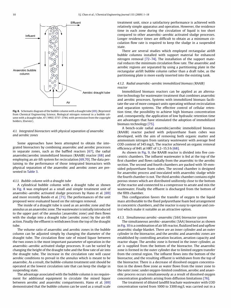
10 Y.J. Chan et al. / Chemical Engineeri
Ffuh
4a
giaetps
4
iaap
atwat
cdtactaaos
mbd
ig. 8. Schematic diagram of the bubble column with a draught tube [69]. (Reprintedrom Chemical Engineering Science, Biological nitrogen removal in a bubble col-mn with a draught tube, 47 (1992) 3737–3744, with permission from the copyrightolders, Elsevier).
.1. Integrated bioreactors with physical separation of anaerobicnd aerobic zones
Some approaches have been attempted to obtain the inte-rated bioreactors by combining anaerobic and aerobic processesn separate zones, such as the baffled reactors [67], the radialnaerobic/aerobic immobilized biomass (RAAIB) reactor [68] andmploying an air-lift system for recirculation [69,70]. The data per-aining to the performance of those integrated bioreactors withhysical separation of the anaerobic and aerobic zones are pre-ented in Table 3.
.1.1. Bubble column with a draught tubeA cylindrical bubble column with a draught tube as shown
n Fig. 8 was employed as a small and simple treatment unit ofnaerobic–aerobic activated sludge processes by Hano et al. [69]nd more recently Bando et al. [71]. The performances of the unitroposed were evaluated based on the nitrogen removal.
The inside of a draught tube is used as an aerobic zone and thennulus as an anaerobic zone. The wastewater is initially introducedo the upper part of the annulus (anaerobic zone) and then flowsith the sludge into a draught tube (aerobic zone) by the air-lift
ction. Finally the effluent is withdrawn from the top of the draughtube.
The volume ratio of anaerobic and aerobic zones in the bubbleolumn can be adjusted simply by changing the diameter of theraught tube. The circulation flow rate of mixed liquor betweenhe two zones is the most important parameter of operation in thenaerobic–aerobic activated sludge processes. It can be varied byhanging the height of the draught tube and the flow rate of air intohe draught tube. The increase in the circulation rate will causeerobic conditions to prevail in the annulus which is meant to benaerobic. As a result, the bubble-column treatment unit should beperated at the lowest circulation rate that can keep the sludge in
uspending state.The advantage associated with the bubble column is no require-ent for additional equipment to circulate the mixed liquor
etween aerobic and anaerobic compartments. Hano et al. [69]emonstrated that the bubble column can be used as a small scale
ng Journal 155 (2009) 1–18
treatment unit, since a satisfactory performance is achieved withrelatively simple apparatus and operation. However, the residencetime in each zone during the circulation of liquid is too shortcompared to other anaerobic–aerobic activated sludge processes.Longer residence times are difficult to obtain as a minimum cir-culation flow rate is required to keep the sludge in a suspendedstate.
There are several studies which employed rectangular airliftbubble columns installed with support material for enhancednitrogen removal [72–74]. The installation of the support mate-rial reduces the minimum circulation flow rate. The anaerobic andaerobic regions are separated by using a partitioning plate in therectangular airlift bubble column rather than a draft tube, as thepartitioning plate is more easily inserted into the existing tank.
4.1.2. Radial anaerobic–aerobic immobilized biomass (RAAIB)reactor
Immobilized biomass reactors can be applied as an alterna-tive technology for wastewater treatment that combines anaerobicand aerobic processes. Systems with immobilized biomass facili-tate the use of more compact units operating without recirculationand separation systems. The effective control of cellular reten-tion time, the possibility to achieve high biomass concentrationand, consequently, the application of low hydraulic retention timeare advantages that have stimulated the adoption of immobilizedbiomass technology [75].
A bench-scale radial anaerobic/aerobic immobilized biomass(RAAIB) reactor packed with polyurethane foam cubes wasdeveloped, with the aim of removing both organic matter andammonium nitrogen from sanitary wastewater with average feedCOD content of 345 mg/L. The reactor achieved an organic removalefficiency of 84% at HRT of 1.2–15.5 h [68].
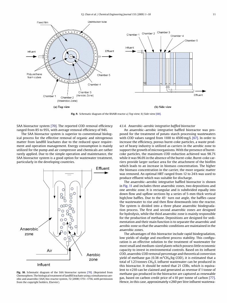
As shown in Fig. 9, the RAAIB reactor is divided into five con-centric chambers. The influent wastewater is fed at the top of thefirst chamber and flows radially from the anaerobic to the aerobicsection. The second and fourth chambers are packed with 10-mm-sided polyurethane foam cubes. The second chamber is designedfor anaerobic process and inoculated with anaerobic sludge whilethe fourth chamber is not. The third aerobic chamber contains eightporous stones which are distributed uniformly close to the bottomof the reactor and connected to a compressor to aerate and mix thewastewater. Finally the effluent is discharged from the bottom ofthe fifth chamber.
This configuration favors the transfer of oxygen to the liquidmass attributable to the fixed polyurethane foam bed arrangementin concentric chambers, and the reactor is easy to operate and con-trol which make it suitable as an attractive option.
4.1.3. Simultaneous aerobic–anaerobic (SAA) bioreactor systemThe simultaneous aerobic–anaerobic (SAA) bioreactor as shown
in Fig. 10 is a combination of air lift reactor, fluidized bed and upflowanaerobic sludge blanket. There are an inner cylinder and an outercylinder in the bioreactor, and the aerobic and anaerobic zones areestablished by controlling aeration location, aeration capacity andreactor shape. The aerobic zone is formed in the inner cylinder, asair is supplied from the bottom of the bioreactor. The anaerobiczone is formed in the outer cylinder due to limited oxygen transferfrom the central region. The influent flows into the bottom of thebioreactor, and the resulting effluent is withdrawn from the top ofthe bioreactor. There is a decrease of dissolved oxygen concentra-tion in the down flow zone as water flows from the inner zone to
the outer zone; under oxygen-limited condition, aerobic and anaer-obic process occurs simultaneously as a result of dissolved oxygenconcentration gradients arising from diffusion limitations [76].The treatment of diluted landfill leachate wastewater with CODconcentration varied from 1000 to 3300 mg/L was carried out in a
Y.J. Chan et al. / Chemical Engineering Journal 155 (2009) 1–18 11
AIB re
Sr
immurSp
FCof
Fig. 9. Schematic diagram of the RA
AA bioreactor system [70]. The reported COD removal efficiencyanged from 85 to 95%, with average removal efficiency of 94%.
The SAA bioreactor system is superior to conventional biolog-cal process for the effective removal of organic and nitrogenous
atter from landfill leachates due to the reduced space require-
ent and operation management. Energy consumption is mainlytilized for the pump and air compressor and chemicals are ratherarely applied. Due to the simple operation and maintenance, theAA bioreactor system is a good option for wastewater treatment,articularly in the developing countries.
ig. 10. Schematic diagram of the SAA bioreactor system [70]. (Reprinted fromhemosphere, The biological treatment of landfill leachate using a simultaneous aer-bic and anaerobic (SAA) bio-reactor system, 72 (2008) 1751–1756, with permissionrom the copyright holders, Elsevier).
actor a) Top view; b) Side view [68].
4.1.4. Anaerobic–aerobic integrative baffled bioreactorAn anaerobic–aerobic integrative baffled bioreactor was pro-
posed for the treatment of potato starch processing wastewaterswith COD values ranged from 1100 to 4500 mg/L [67]. In order toincrease the efficiency, porous burnt-coke particles, a waste prod-uct of heavy industry is utilized as carriers in the aerobic zone tosupport the growth of microorganisms. With the presence of burnt-coke particles, the maximum COD reduction achieved was 98.7%while it was 96.0% in the absence of the burnt-coke. Burnt-coke car-riers provide larger surface area for the attachment of the biofilmwhich leads to an increase in biomass concentration. The higherthe biomass concentration in the carrier, the more organic matterwas removed. An optimal HRT ranged from 12 to 24 h was used toproduce effluent which was suitable for discharge.
The anaerobic–aerobic integrative baffled bioreactor is shownin Fig. 11 and includes three anaerobic zones, two depositions andone aerobic zone. It is rectangular and is subdivided equally intodown flow and upflow sections by a series of 5-mm thick verticalhigh/low baffles. Due to the 45◦ turn out angle, the baffles causethe wastewater to rise and then flow downwards into the reactor.The system is divided into a three phase anaerobic biodegrada-tion process. The first and second anaerobic zones are designedfor hydrolysis, while the third anaerobic zone is mainly responsiblefor the production of methane. Depositions are designed for sedi-mentation and their main function is to separate the anaerobic andaerobic zone so that the anaerobic conditions are maintained in theanaerobic zones.
The advantages of this bioreactor include rapid biodegradation,low yields of sludge and excellent process stability. This configu-ration is an effective solution to the treatment of wastewater formost small and medium-sized plants which possess little economiccapacity to invest in environmental controls. Based on its influentCOD, anaerobic COD removal percentage and theoretical conversionyield of methane gas (0.38 m3CH4/kg COD), it is estimated that atotal of 1.23 tonnes CH4/L influent wastewater can be produced in
this bioreactor. It should be noted that 21 CERs, which is equiva-lent to D210 can be claimed and generated as revenue if 1 tonne ofmethane gas produced in the bioreactor are captured as renewablegas, based on carbon credit price of D10 per tonne of carbon [77].Hence, in this case, approximately D260 per litre influent wastewa-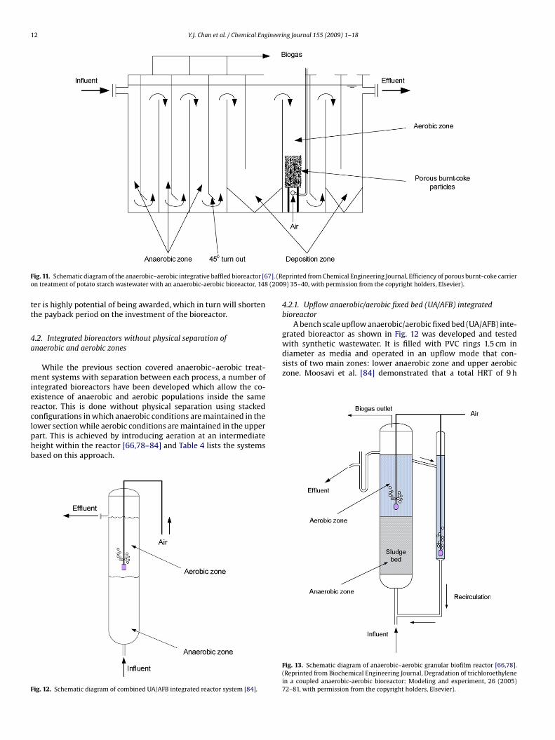
12 Y.J. Chan et al. / Chemical Engineering Journal 155 (2009) 1–18
F 7]. (Ro (200
tt
4a
mierclphb
F
with synthetic wastewater. It is filled with PVC rings 1.5 cm indiameter as media and operated in an upflow mode that con-sists of two main zones: lower anaerobic zone and upper aerobiczone. Moosavi et al. [84] demonstrated that a total HRT of 9 h
ig. 11. Schematic diagram of the anaerobic–aerobic integrative baffled bioreactor [6n treatment of potato starch wastewater with an anaerobic-aerobic bioreactor, 148
er is highly potential of being awarded, which in turn will shortenhe payback period on the investment of the bioreactor.
.2. Integrated bioreactors without physical separation ofnaerobic and aerobic zones
While the previous section covered anaerobic–aerobic treat-ent systems with separation between each process, a number of
ntegrated bioreactors have been developed which allow the co-xistence of anaerobic and aerobic populations inside the sameeactor. This is done without physical separation using stackedonfigurations in which anaerobic conditions are maintained in the
ower section while aerobic conditions are maintained in the upperart. This is achieved by introducing aeration at an intermediateeight within the reactor [66,78–84] and Table 4 lists the systemsased on this approach.ig. 12. Schematic diagram of combined UA/AFB integrated reactor system [84].
eprinted from Chemical Engineering Journal, Efficiency of porous burnt-coke carrier9) 35–40, with permission from the copyright holders, Elsevier).
4.2.1. Upflow anaerobic/aerobic fixed bed (UA/AFB) integratedbioreactor
A bench scale upflow anaerobic/aerobic fixed bed (UA/AFB) inte-grated bioreactor as shown in Fig. 12 was developed and tested
Fig. 13. Schematic diagram of anaerobic–aerobic granular biofilm reactor [66,78].(Reprinted from Biochemical Engineering Journal, Degradation of trichloroethylenein a coupled anaerobic-aerobic bioreactor: Modeling and experiment, 26 (2005)72–81, with permission from the copyright holders, Elsevier).
ineering Journal 155 (2009) 1–18 13
(e7httTwpct
4
tpahlblac
gtfopbbsama
wiciao
Ooawaaitai40wtimr
rnadd
Y.J. Chan et al. / Chemical Eng
5 h for anaerobic and 4 h for aerobic) is sufficient to accomplishfficient COD removal with more than 95% at OLR as high as.4 kg COD/m3 d. The UA/AFB bioreactor is capable of handlingigh organic loads and able to recover immediately after any dis-urbances. The UA/AFB bioreactor is a potential biotechnology forreatment of industrial wastewater containing high organic loads.he study did not incorporate a methane gas capture system, whichould produce biogas to partially offset the cost of treatment. It isrojected that the bioreactor manages to attain approximately 20arbon credit per liter of influent wastewater, which is equivalento D200.
.2.2. Anaerobic–aerobic granular biofilm bioreactorSimilar in design to a UA/AFB reactor, a granular biofilm bioreac-
or consists of an UASB with either an aeration column or a spargerlaced in the middle part of the reactor. A schematic diagram ofnaerobic–aerobic granular biofilm reactor is presented in Fig. 13. Itas been utilized in the biodegradation of various chlorinated pol-
utants such as trichloethylene (TCE) [66,78] and polychlorinatediphenyl (PCB) [82]. The biodegradation of various chlorinated pol-
utants is based on the co-existence of aerobic methanotrophic andnaerobic methanogenic bacteria in a biofilm under oxygen-limitedonditions.
Oxygen consumption by aerobic bacteria results in a steep oxy-en gradient across the biofilm, leaving the interior a sufficientlyhick biofilm free of oxygen and thereby provides a suitable nicheor the growth of anaerobic methanogenic bacteria. Simultane-usly, methane produced by the methanogens combined with theresence of oxygen favors the growth of aerobic methanotrophicacteria in the outer layer of the biomass granules. Thus, anaero-ic and aerobic populations of the biofilm co-exist closely in theame reactor system. It is a good strategy since both reductivend oxidative biotransformation occurs concomitantly to completeineralization of highly substituted compounds under micro-
eration.UASB reactors can accommodate low concentrations of oxygen
ithout detrimental effects on the integrity or metabolic activ-ty of the granular biomass. Thus, a partially aerated UASB reactorontains the substrates required by methanotrophic bacteria (i.e.,ndigenously produced methane and exogenously added oxygen)nd could be an ideal system for maintaining consortia composedf methanogens and methanotrophs [78].
Shen and Guiot [79] investigated the impact of influent dissolved2, on the characteristics of anaerobic granular sludge at vari-us dissolved O2 concentrations (0.5–8.1 mg/L) via laboratory-scalenaerobic–aerobic granular biofilm bioreactor with a syntheticastewater (carbon sources containing 75% sucrose and 25%
cetate). As the granules are able to maintain good methanogenicctivities when dissolved O2 is present in the recirculated fluid,t indicates that the anaerobic–aerobic granular biofilm bioreac-or can be successfully operated to maintain both active strictnaerobes and aerobes at the same time. With the elevatednfluent dissolved O2, the methane yield declined from 64 to2% of influent COD while the CO2 generation rate rose from.23 to 0.39 L (CO2)/g COD, suggesting more organic substrateas aerobically mineralized under high dissolved O2 condi-
ions. However, in spite of significant aerobic COD eliminationn the coupled reactors receiving high dissolved O2 influent, a
ajor part of the influent COD (at least 62%) was anaerobicallyemoved.
However, the presence of dissolved O2 in the recirculated fluid
esulted in fluffy biolayers on the granule surface, which imposed aegative impact on the settleability of granular sludge and causedslightly higher sludge washout. The negative impact of influentissolved O2 on the granule structure and settleability represent arawback for the practical operation of the reactor.
Fig. 14. Schematic diagram of staged anaerobic–aerobic MBR [83]. (Reprinted fromProcess Biochemistry, The integration of methanogensis with simultaneous nitri-fication and denitrification in a membrane bioreactor, 40 (2005) 541–547, withpermission from the copyright holders, Elsevier).
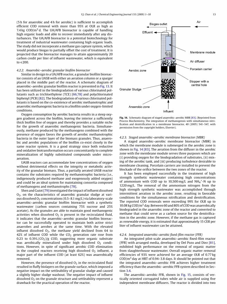
4.2.3. Staged anaerobic–aerobic membrane bioreactor (MBR)A staged anaerobic–aerobic membrane bioreactor (MBR) in
which the membrane module is submerged in the aerobic zone isshown in Fig. 14 [83]. The aeration from the diffuser in the aerobiczone with the membrane module serves three purposes which are(i) providing oxygen for the biodegradation of substrates, (ii) mix-ing of the aerobic tank, and (iii) producing turbulence desirable tomembrane cleaning. Porcelain carriers are installed to prevent theblockade of the orifice between the two zones of the reactor.
It has been employed successfully in the treatment of highstrength synthetic wastewater containing high concentrationsof ammonium with COD up to 10,500 mg/L and NH4
+-N up to1220 mg/L. The removal of the ammonium nitrogen from thehigh strength synthetic wastewater was accomplished throughintermittent aeration in the aerobic zone, resulting in favorableconditions for the simultaneous nitrification and denitrification.The reported COD removals were exceeding 99% for OLR up to10.08 kg COD/m3 day. Between 60 and 80% of COD was anaerobicallybiodegraded in the anaerobic zone of the reactor and converted tomethane that could serve as a carbon source for the denitrifica-tion in the aerobic zone. However, if the methane gas is capturedas renewable energy, it is estimated that approximately 15 CER perliter of influent wastewater can be attained.
4.2.4. Integrated anaerobic–aerobic fixed-film reactor (FFR)An integrated pilot-scale anaerobic–aerobic fixed-film reactor
(FFR) with arranged media, developed by Del Pozo and Diez [81],exhibited high performance on the removal of organic matterfrom slaughterhouse wastewater. Overall organic matter removalefficiencies of 93% were achieved for an average OLR of 0.77 kgCOD/m3 day at HRT of 0.94–3.8 days. It should be pointed out thatthe integrated anaerobic–aerobic FFR achieves higher treatment
efficiency than the anaerobic–aerobic FFB system described in Sec-tion 3.4.The anaerobic–aerobic FFR, shown in Fig. 15, consists of ver-tically oriented corrugated tubes while air is supplied using fiveindependent membrane diffusers. The reactor is divided into two
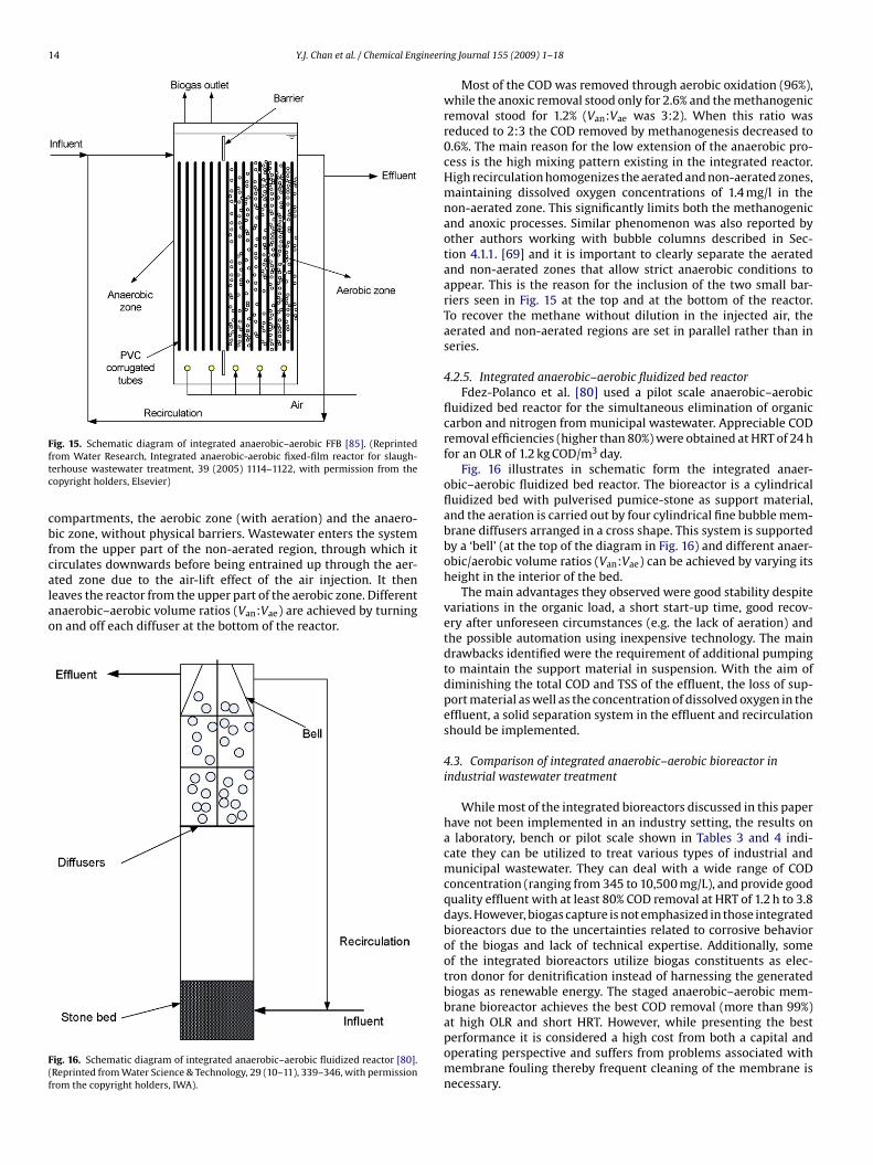
14 Y.J. Chan et al. / Chemical Engineeri
Fftc
cbfcalao
F(f
ig. 15. Schematic diagram of integrated anaerobic–aerobic FFB [85]. (Reprintedrom Water Research, Integrated anaerobic-aerobic fixed-film reactor for slaugh-erhouse wastewater treatment, 39 (2005) 1114–1122, with permission from theopyright holders, Elsevier)
ompartments, the aerobic zone (with aeration) and the anaero-ic zone, without physical barriers. Wastewater enters the systemrom the upper part of the non-aerated region, through which itirculates downwards before being entrained up through the aer-
ted zone due to the air-lift effect of the air injection. It theneaves the reactor from the upper part of the aerobic zone. Differentnaerobic–aerobic volume ratios (Van:Vae) are achieved by turningn and off each diffuser at the bottom of the reactor.ig. 16. Schematic diagram of integrated anaerobic–aerobic fluidized reactor [80].Reprinted from Water Science & Technology, 29 (10–11), 339–346, with permissionrom the copyright holders, IWA).
ng Journal 155 (2009) 1–18
Most of the COD was removed through aerobic oxidation (96%),while the anoxic removal stood only for 2.6% and the methanogenicremoval stood for 1.2% (Van:Vae was 3:2). When this ratio wasreduced to 2:3 the COD removed by methanogenesis decreased to0.6%. The main reason for the low extension of the anaerobic pro-cess is the high mixing pattern existing in the integrated reactor.High recirculation homogenizes the aerated and non-aerated zones,maintaining dissolved oxygen concentrations of 1.4 mg/l in thenon-aerated zone. This significantly limits both the methanogenicand anoxic processes. Similar phenomenon was also reported byother authors working with bubble columns described in Sec-tion 4.1.1. [69] and it is important to clearly separate the aeratedand non-aerated zones that allow strict anaerobic conditions toappear. This is the reason for the inclusion of the two small bar-riers seen in Fig. 15 at the top and at the bottom of the reactor.To recover the methane without dilution in the injected air, theaerated and non-aerated regions are set in parallel rather than inseries.
4.2.5. Integrated anaerobic–aerobic fluidized bed reactorFdez-Polanco et al. [80] used a pilot scale anaerobic–aerobic
fluidized bed reactor for the simultaneous elimination of organiccarbon and nitrogen from municipal wastewater. Appreciable CODremoval efficiencies (higher than 80%) were obtained at HRT of 24 hfor an OLR of 1.2 kg COD/m3 day.
Fig. 16 illustrates in schematic form the integrated anaer-obic–aerobic fluidized bed reactor. The bioreactor is a cylindricalfluidized bed with pulverised pumice-stone as support material,and the aeration is carried out by four cylindrical fine bubble mem-brane diffusers arranged in a cross shape. This system is supportedby a ‘bell’ (at the top of the diagram in Fig. 16) and different anaer-obic/aerobic volume ratios (Van:Vae) can be achieved by varying itsheight in the interior of the bed.
The main advantages they observed were good stability despitevariations in the organic load, a short start-up time, good recov-ery after unforeseen circumstances (e.g. the lack of aeration) andthe possible automation using inexpensive technology. The maindrawbacks identified were the requirement of additional pumpingto maintain the support material in suspension. With the aim ofdiminishing the total COD and TSS of the effluent, the loss of sup-port material as well as the concentration of dissolved oxygen in theeffluent, a solid separation system in the effluent and recirculationshould be implemented.
4.3. Comparison of integrated anaerobic–aerobic bioreactor inindustrial wastewater treatment
While most of the integrated bioreactors discussed in this paperhave not been implemented in an industry setting, the results ona laboratory, bench or pilot scale shown in Tables 3 and 4 indi-cate they can be utilized to treat various types of industrial andmunicipal wastewater. They can deal with a wide range of CODconcentration (ranging from 345 to 10,500 mg/L), and provide goodquality effluent with at least 80% COD removal at HRT of 1.2 h to 3.8days. However, biogas capture is not emphasized in those integratedbioreactors due to the uncertainties related to corrosive behaviorof the biogas and lack of technical expertise. Additionally, someof the integrated bioreactors utilize biogas constituents as elec-tron donor for denitrification instead of harnessing the generatedbiogas as renewable energy. The staged anaerobic–aerobic mem-brane bioreactor achieves the best COD removal (more than 99%)
at high OLR and short HRT. However, while presenting the bestperformance it is considered a high cost from both a capital andoperating perspective and suffers from problems associated withmembrane fouling thereby frequent cleaning of the membrane isnecessary.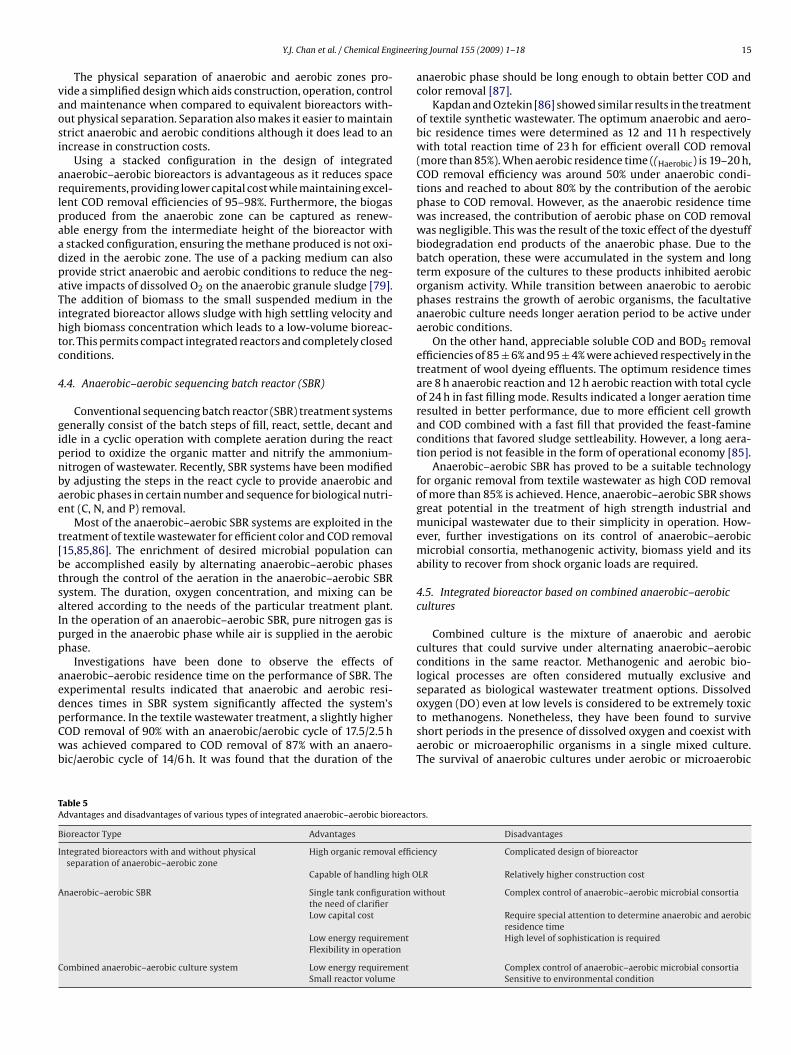
ineeri
vaosi
arlpaadpaTihtc
4
gipnbae
t[btsaIpp
aedpCwb
TA
B
I
A
C
Y.J. Chan et al. / Chemical Eng
The physical separation of anaerobic and aerobic zones pro-ide a simplified design which aids construction, operation, controlnd maintenance when compared to equivalent bioreactors with-ut physical separation. Separation also makes it easier to maintaintrict anaerobic and aerobic conditions although it does lead to anncrease in construction costs.
Using a stacked configuration in the design of integratednaerobic–aerobic bioreactors is advantageous as it reduces spaceequirements, providing lower capital cost while maintaining excel-ent COD removal efficiencies of 95–98%. Furthermore, the biogasroduced from the anaerobic zone can be captured as renew-ble energy from the intermediate height of the bioreactor withstacked configuration, ensuring the methane produced is not oxi-ized in the aerobic zone. The use of a packing medium can alsorovide strict anaerobic and aerobic conditions to reduce the neg-tive impacts of dissolved O2 on the anaerobic granule sludge [79].he addition of biomass to the small suspended medium in the
ntegrated bioreactor allows sludge with high settling velocity andigh biomass concentration which leads to a low-volume bioreac-or. This permits compact integrated reactors and completely closedonditions.
.4. Anaerobic–aerobic sequencing batch reactor (SBR)
Conventional sequencing batch reactor (SBR) treatment systemsenerally consist of the batch steps of fill, react, settle, decant anddle in a cyclic operation with complete aeration during the reacteriod to oxidize the organic matter and nitrify the ammonium-itrogen of wastewater. Recently, SBR systems have been modifiedy adjusting the steps in the react cycle to provide anaerobic anderobic phases in certain number and sequence for biological nutri-nt (C, N, and P) removal.
Most of the anaerobic–aerobic SBR systems are exploited in thereatment of textile wastewater for efficient color and COD removal15,85,86]. The enrichment of desired microbial population cane accomplished easily by alternating anaerobic–aerobic phaseshrough the control of the aeration in the anaerobic–aerobic SBRystem. The duration, oxygen concentration, and mixing can beltered according to the needs of the particular treatment plant.n the operation of an anaerobic–aerobic SBR, pure nitrogen gas isurged in the anaerobic phase while air is supplied in the aerobichase.
Investigations have been done to observe the effects ofnaerobic–aerobic residence time on the performance of SBR. Thexperimental results indicated that anaerobic and aerobic resi-
ences times in SBR system significantly affected the system’serformance. In the textile wastewater treatment, a slightly higherOD removal of 90% with an anaerobic/aerobic cycle of 17.5/2.5 has achieved compared to COD removal of 87% with an anaero-ic/aerobic cycle of 14/6 h. It was found that the duration of the
able 5dvantages and disadvantages of various types of integrated anaerobic–aerobic bioreacto
ioreactor Type Advantages
ntegrated bioreactors with and without physicalseparation of anaerobic–aerobic zone
High organic removal effici
Capable of handling high O
naerobic–aerobic SBR Single tank configuration wthe need of clarifierLow capital cost
Low energy requirementFlexibility in operation
ombined anaerobic–aerobic culture system Low energy requirementSmall reactor volume
ng Journal 155 (2009) 1–18 15
anaerobic phase should be long enough to obtain better COD andcolor removal [87].
Kapdan and Oztekin [86] showed similar results in the treatmentof textile synthetic wastewater. The optimum anaerobic and aero-bic residence times were determined as 12 and 11 h respectivelywith total reaction time of 23 h for efficient overall COD removal(more than 85%). When aerobic residence time ((Haerobic) is 19–20 h,COD removal efficiency was around 50% under anaerobic condi-tions and reached to about 80% by the contribution of the aerobicphase to COD removal. However, as the anaerobic residence timewas increased, the contribution of aerobic phase on COD removalwas negligible. This was the result of the toxic effect of the dyestuffbiodegradation end products of the anaerobic phase. Due to thebatch operation, these were accumulated in the system and longterm exposure of the cultures to these products inhibited aerobicorganism activity. While transition between anaerobic to aerobicphases restrains the growth of aerobic organisms, the facultativeanaerobic culture needs longer aeration period to be active underaerobic conditions.
On the other hand, appreciable soluble COD and BOD5 removalefficiencies of 85 ± 6% and 95 ± 4% were achieved respectively in thetreatment of wool dyeing effluents. The optimum residence timesare 8 h anaerobic reaction and 12 h aerobic reaction with total cycleof 24 h in fast filling mode. Results indicated a longer aeration timeresulted in better performance, due to more efficient cell growthand COD combined with a fast fill that provided the feast-famineconditions that favored sludge settleability. However, a long aera-tion period is not feasible in the form of operational economy [85].
Anaerobic–aerobic SBR has proved to be a suitable technologyfor organic removal from textile wastewater as high COD removalof more than 85% is achieved. Hence, anaerobic–aerobic SBR showsgreat potential in the treatment of high strength industrial andmunicipal wastewater due to their simplicity in operation. How-ever, further investigations on its control of anaerobic–aerobicmicrobial consortia, methanogenic activity, biomass yield and itsability to recover from shock organic loads are required.
4.5. Integrated bioreactor based on combined anaerobic–aerobiccultures
Combined culture is the mixture of anaerobic and aerobiccultures that could survive under alternating anaerobic–aerobicconditions in the same reactor. Methanogenic and aerobic bio-logical processes are often considered mutually exclusive andseparated as biological wastewater treatment options. Dissolved
oxygen (DO) even at low levels is considered to be extremely toxicto methanogens. Nonetheless, they have been found to surviveshort periods in the presence of dissolved oxygen and coexist withaerobic or microaerophilic organisms in a single mixed culture.The survival of anaerobic cultures under aerobic or microaerobicrs.
Disadvantages
ency Complicated design of bioreactor
LR Relatively higher construction cost
ithout Complex control of anaerobic–aerobic microbial consortia
Require special attention to determine anaerobic and aerobicresidence timeHigh level of sophistication is required
Complex control of anaerobic–aerobic microbial consortiaSensitive to environmental condition
1 ineeri
ceao
thtWDrtflmIOb
co(abceter
wmrsrgpfapaw
ctsrctecas
4b
gasbctmd
6 Y.J. Chan et al. / Chemical Eng
onditions (i.e. DO concentration < 1 mg/L) is due to the intrinsic tol-rance or formation of anaerobic niches [88]. As a result, combinednaerobic–aerobic cultures have been investigated increasinglyver the last two decades [88–96].
Combined cultures have been applied successfully in thereatment of several contaminants such as polycyclic aromaticydrocarbons, and highly chlorinated solvents that require sequen-ially operated anaerobic and aerobic or anoxic reactors [90,94,95].
ith free or co-immobilized cultures of anaerobes and aerobes,O concentrations display alternating values. The oxygen gradient
esults in alternating conditions from aerobic to anaerobic eitherhrough the reactor content (as in packed bed or slurry reactors) orrom bulk liquid to the depths of the immobilized cocultures. Thiseads to possible living conditions for different types of bacteria and
akes the coexistence of anaerobic and aerobic cultures feasible.nterestingly, others have identified that with the addition of 4 mg
2/L day to essentially anaerobic cultures, methane production haseen doubled when algae was the primary substrate [97].
For low strength municipal wastewaters treatment, combinedultures from a mixture of anaerobic granular and suspended aer-bic cultures (40:60, v/v) were developed in an upflow sludge bedUSB) reactors. The combined cultures in USB reactor exhibitedverage BOD removal efficiency of 52–76% at HRT of 0.75 day. Com-ined cultures which were aerated every other day (i.e. alternatingyclic anaerobic to microaerobic/aerobic conditions) were consid-red as the optimum and feasible aeration protocol as comparedo aeration for 4 h/day or continuously due to their higher removalfficiencies, slightly better settling characteristic and lower oxygenequirement [88].
Appreciable COD removal efficiencies (greater than 93%)ere reported in the study of sucrose biotransformation underethanogenic and oxygen-limited conditions in bench-scale batch
eactors seeded with a mixture containing anaerobic digesterludge and aerobic mixed liquor. In addition to oxygen-limitedeactors, anaerobic (methanogenic) and aerobic (dissolved oxygenreater than 2.0 mg/l) systems were operated in parallel for com-arison. It was observed that the overall COD removal efficiencies
or oxygen-limited cultures, strictly anaerobic cultures, and strictlyerobic cultures were comparable under the complete-mix, sus-ended growth conditions. The limited-aeration conditions werechieved by introducing air through a timer-actuated solenoid valvehich was open for 15 seconds in every half-hour [91].
Integrated bioreactors containing anaerobic–aerobic culturesan be beneficial compared to conventional anaerobic and aerobicreatment system due to their achievement of required dischargetandards, prevention of biomass loss, high settling characteristic,educed aeration and additional methane production. Combinedultures are perceived as an energy efficient treatment alternativeo achieve low final COD concentrations, minimal biosolids gen-ration, and mineralization of a broad range of specific organichemicals. Nonetheless, further research is required to address thepplication and process control issues of these types of bioreactorystems.
.6. Overall comparison of the integrated anaerobic–aerobicioreactors
The advantages and disadvantages of the four types of inte-rated anaerobic–aerobic bioreactors are presented in Table 5. Thenaerobic–aerobic SBR and combined anaerobic–aerobic cultureystem require less energy input than either types of integrated
ioreactors, as less aeration is required. However, inappropriateontrol of anaerobic and aerobic residences times in SBR sys-em will result in difficulties controlling the anaerobic–aerobicicrobial consortia and thus the selection and enrichment of theesired microbial population will be difficult to achieve. A high
ng Journal 155 (2009) 1–18
level of sophistication is required in timing units, controller, soft-ware and censors while automated switches and valves are requiredto achieve efficient organic removal in anaerobic–aerobic SBR sys-tem.
For combined anaerobic–aerobic culture system, control of aer-ation time and maintenance of oxygen limited condition in thebioreactor are critical as methanogens are sensitive to the pres-ence of dissolved oxygen. Excessive dissolved oxygen concentrationwill restrain methanogenic activity and adversely affect the perfor-mance of the system.
Integrated bioreactors with and without physical separationof anaerobic–aerobic zone have exhibited the best performancein terms of COD removal and are capable of handling high OLRwhen compared to the anaerobic–aerobic SBR and combinedanaerobic–aerobic culture system. However, the design and con-figuration of integrated bioreactor are more complicated andtherefore, its construction cost inevitably would be higher thananaerobic–aerobic SBR system and combined anaerobic–aerobicculture system. With proper installation of methane gas captur-ing system, integrated anaerobic–aerobic bioreactor emerges asa viable technology in treating high strength industrial wastewa-ters, in which it offers an attractive energy recovery source whilereducing greenhouse gas emissions. This may in the future leadto it being awarded carbon credits from the Clean DevelopmentMechanism (CDM), further shortening the payback period forinvestment.
5. Conclusion
Anaerobic–aerobic treatments receive great attention over thepast decades due to their numerous advantages such as lowenergy consumption, low chemical consumption, low sludgeproduction, vast potential of resource recovery, less equipmentrequired and high operational simplicity. However, conventionalanaerobic–aerobic systems are found to have operational limita-tions in terms of long HRT, space requirement and facilities tocapture biogas. The applications of newly developed high rate biore-actors address these limitations and provide increased organicmatter removal at shorter HRT and higher methane yields for biogasproduction.
In order to meet strict constraints with respect to space, odorsand minimal sludge production, considerable attention has beendirected towards the integrated anaerobic–aerobic bioreactorswhich combine the aerobic and anaerobic process in a single biore-actor. With simple yet cost effective technology, the generation ofrenewable energy and outstanding treatment efficiency, it is envis-aged that the compact integrated bioreactors will be able to treata wide range of high organic strength industrial and municipalwastewater. However, most of the integrated bioreactors reportedin this work lack large scale implementation within industry andfurther work is required to evaluate the performance of thesepromising reactors on a larger scale. Besides, further improvementssuch as installation of biogas capture system and utilization of sus-pended carrier or packing medium are considered essential.
As such, the integrated bioreactors can attain carbon creditderived from Clean Development Mechanism (CDM) under KyotoProtocol 1997, shifting the paradigm of wastewater managementfrom ‘treatment and disposal’ to ‘beneficial utilization’ as well as‘profitable endeavor’.
References
[1] W.J. Ng, Industrial Wastewater Treatment, World Scientific Publishing Com-pany, 2006.
[2] Metcalf and Eddy, Wastewater Engineering Treatment and Reuse, fourth ed.,McGraw Hill, 2003.
ineeri
[
[
[
[
[
[
[
[[
[
[
[
[
[
[
[
[
[
[
[
[
[
[
[
[
[
[
[
[
[
[
[
[
[
[
[
[
[
[
[
[
[
[
[
[
[
[
[
[
[
[
Y.J. Chan et al. / Chemical Eng
[3] D.T. Sponza, A. Uluköy, Treatment of 2,4-dichlorophenol (DCP) in a sequentialanaerobic (upflow anaerobic sludge blanket) aerobic (completely stirred tank)reactor system, Process Biochemistry 40 (2005) 3419–3428.
[4] B.G. Yeoh, Anaerobic treatment of industrial wastewaters in Malaysia, in: PostConference Seminar on Industrial Wastewater Management in Malaysia, KualaLumpur, Malaysia, 1995.
[5] L. Seghezzo, G. Zeeman, J.B. van Lier, H.V.M. Hamelers, G. Lettinga, A review:The anaerobic treatment of sewage in UASB and EGSB reactors, BioresourceTechnology 65 (1998) 175–190.
[6] F.Y. Cakir, M.K. Stenstrom, Greenhouse gas production: a comparison betweenaerobic and anaerobic wastewater treatment technology, Water Research 39(2005) 4197–4203.
[7] C.P. Leslie Grady Jr., G.T. Daigger, H.C. Lim, Biological Wastewater Treatment,second ed., revised and expanded, CRC Press, 1999.
[8] J.J. Heijnen, A. Mulder, R. Weltevrede, J. Hols, H. Vanleeuwen, Large-scaleanaerobic–aerobic treatment of complex industrial-waste water using biofilmreactors, Water Science and Technology 23 (1991) 1427–1436.
[9] N.F. Gray, Water Technology: An Introduction for Environmental Scientists andEngineers, Elsevier, Oxford, 2005.
10] G.G. Aggelis, H.N. Gavala, G. Lyberatos, Combined, separate aerobic and anaero-bic biotreatment of green olive debittering wastewater, Journal of AgriculturalEngineering Research 80 (2001) 283–292.
11] M. Vera, E. Aspe, M.C. Marti, M. Roeckel, Optimization of a sequentialanaerobic–aerobic treatment of a saline fishing effluent, Process Safety andEnvironmental Protection 77 (1999) 275–290.
12] B. Frostell, Anaerobic–Aerobic Biological Treatment of Starch Industry WasteWaters, Starch—Stärke 35 (1983) 185–189.
13] F.J. Cervantes, S.G. Pavlostathis, A.C. van Haandel, Advanced Biological Treat-ment Processes for Industrial Wastewaters: Principles and Applications, IWAPublishing, 2006.
14] M. Ros, G.D. Zupancic, Two-stage thermophilic anaerobic–aerobic digestion ofwaste-activated sludge, Environmental Engineering Science 21 (2004) 617–626.
15] N. Supaka, K. Juntongjin, S. Damronglerd, M.-L. Delia, P. Strehaiano, Microbialdecolorization of reactive azo dyes in a sequential anaerobic–aerobic system,Chemical Engineering Journal 99 (2004) 169–176.
16] H. Liu, C. Yang, W. Pu, J. Zhang, Removal of nitrogen from wastewater for reusingto boiler feed-water by an anaerobic/aerobic/membrane bioreactor, ChemicalEngineering Journal 140 (2008) 122–129.
17] L.K. Wang, Waste Treatment in the Process Industries, CRC Press, 2005.18] Y.T. Ahn, S.T. Kang, S.R. Chae, C.Y. Lee, B.U. Bae, H.S. Shin, Simultaneous
high-strength organic and nitrogen removal with combined anaerobic upflowbed filter and aerobic membrane bioreactor, Desalination 202 (2007) 114–121.
19] Y. Zhang, L. Yan, L. Chi, X. Long, Z. Mei, Z. Zhang, Startup and operation ofanaerobic EGSB reactor treating palm oil mill effluent, Journal of EnvironmentalSciences 20 (2008) 658–663.
20] O.N. Agdag, D.T. Sponza, Anaerobic/aerobic treatment of municipal landfillleachate in sequential two-stage up-flow anaerobic sludge blanket reactor(UASB)/completely stirred tank reactor (CSTR) systems, Process Biochemistry40 (2005) 895–902.
21] K.V. Lo, P.H. Liao, Anaerobic–aerobic biological treatment of a mixture of cheesewhey and dairy manure, Biological Wastes 28 (1989) 91–101.
22] Y. Zhang, L. Yan, X. Qiao, L. Chi, X. Niu, Z. Mei, Z. Zhang, Integration of biologicalmethod and membrane technology in treating palm oil mill effluent, Journal ofEnvironmental Sciences 20 (2008) 558–564.
23] E.J. La Motta, E. Silva, A. Bustillos, H. Padron, J. Luque, Combinedanaerobic/aerobic secondary municipal wastewater treatment: Pilot-plantdemonstration of the UASB/aerobic solids contact system, Journal of Environ-mental Engineering—ASCE 133 (2007) 397–403.
24] A. Castillo, P. Llabres, J. Mata-Alvarez, A kinetic study of a combinedanaerobic–aerobic system for treatment of domestic sewage, Water Research33 (1999) 1742–1747.
25] J.-h. Im, H.-j. Woo, M.-w. Choi, K.-b. Han, C.-w. Kim, Simultaneous organic andnitrogen removal from municipal landfill leachate using an anaerobic–aerobicsystem, Water Research 35 (2001) 2403–2410.
26] M. Isik, D.T. Sponza, Biological treatment of acid dyeing wastewater using asequential anaerobic/aerobic reactor system, Enzyme and Microbial Technology38 (2006) 887–892.
27] M. Isik, D.T. Sponza, Anaerobic/aerobic sequential treatment of a cotton textilemill wastewater, Journal of Chemical Technology and Biotechnology 79 (2004)1268–1274.
28] M. Isik, D.T. Sponza, Anaerobic/aerobic treatment of a simulated textile wastew-ater, Separation and Purification Technology 60 (2008) 64–72.
29] U. Tezel, E. Guven, T.H. Erguder, G.N. Demirer, Sequential (anaerobic/aerobic)biological treatment of dalaman SEKA Pulp and Paper Industry effluent, WasteManagement 21 (2001) 717–724.
30] D.T. Sponza, P. Demirden, Treatability of sulfamerazine in sequential upflowanaerobic sludge blanket reactor (UASB)/completely stirred tank reactor (CSTR)processes, Separation and Purification Technology 56 (2007) 108–117.
31] N. Gizgis, M. Georgiou, E. Diamadopoulos, Sequential anaerobic/aerobic biolog-
ical treatment of olive mill wastewater and municipal wastewater, Journal ofChemical Technology and Biotechnology 81 (2006) 1563–1569.32] V. Sklyar, A. Epov, M. Gladchenko, D. Danilovich, S. Kalyuzhnyi, Com-bined biologic (anaerobic–aerobic) and chemical treatment of starch industrywastewater, Applied Biochemistry and Biotechnology 109 (2003) 253–262.
[
[
ng Journal 155 (2009) 1–18 17
33] M. von Sperling, V.H. Freire, C.A. de Lemos Chernicharo, Performance evalua-tion of a UASB-activated sludge system treating municipal wastewater, WaterScience and Technology 43 (2001) 323–328.
34] H. Chen, ATP content and biomass activity in sequential anaerobic/aerobic reac-tors, Journal of Zhejiang University Science 5 (2004) 727–732.
35] J. Yu, H. Chen, M. Ji, P.L. Yue, Distribution and change of microbial activity in com-bined UASB and AFB reactors for wastewater treatment, Bioprocess Engineering22 (2000) 315–322.
36] K.V. Lo, P.H. Liao, Anaerobic aerobic biological treatment of screened dairymanure, Biomass 10 (1986) 187–193.
37] R. Del Pozo, V. Diez, Organic matter removal in combined anaerobic–aerobicfixed-film bioreactors, Water Research 37 (2003) 3561–3568.
38] G.R. Pophali, R. Khan, R.S. Dhodapkar, T. Nandy, S. Devotta, Anaerobic–aerobictreatment of purified terephthalic acid (PTA) effluent; a techno-economic alter-native to two-stage aerobic process, Journal of Environmental Management 85(2007) 1024–1033.
39] R.H. Kettunen, J.A. Rintala, Sequential anaerobic–aerobic treatment of sulfur-rich phenolic leachates, Journal of Chemical Technology and Biotechnology 62(1995) 177–184.
40] I.K. Kapdan, S. Alparslan, Application of anaerobic–aerobic sequential treat-ment system to real textile wastewater for color and COD removal, Enzyme andMicrobial Technology 36 (2005) 273–279.
41] M. von Sperling, C.A. de Lemos Chernicharo, Biological Wastewater Treatmentin Warm Climate Regions, IWA Publishing, 2005.
42] A. Vlyssides, E.M. Barampouti, S. Mai, Influence of ferrous iron on the granularityof a UASB reactor, Chemical Engineering Journal 146 (2009) 49–56.
43] A. Torkian, A. Eqbali, S.J. Hashemian, The effect of organic loading rate on theperformance of UASB reactor treating slaughterhouse effluent, Resources Con-servation and Recycling 40 (2003) 1–11.
44] G.-P. Sheng, H.-Q. Yu, H. Cui, Model-evaluation of the erosion behavior ofactivated sludge under shear conditions using a chemical-equilibrium-basedmodel, Chemical Engineering Journal 140 (2008) 241–246.
45] M. Lerner, N. Stahl, N. Galil, Aerobic vs. anaerobic–aerobic biotreatment:Paper mill wastewater, Environmental Engineering Science 24 (2007) 277–285.
46] W.K. Shieh, J.D. Keenan, Fluidized bed biofilm reactor for wastewater treatment,Advances in Biochemical Engineering Biotechnology 33 (1986) 131–169.
47] A.A. Ulson de Souza, H.L. Brandão, I.M. Zamporlini, H.M. Soares, S.M.D.A. GuelliUlson de Souza, Application of a fluidized bed bioreactor for cod reductionin textile industry effluents, Resources, Conservation and Recycling 52 (2008)511–521.
48] J.J. Heijnen, A. Mulder, W. Enger, F. Hoeks, Review on the application of anaero-bic fluidized bed reactors in waste-water treatment, The Chemical EngineeringJournal 41 (1989) B37–B50.
49] V. Lazarova, J. Manem, Advances in biofilm aerobic reactors ensuring effec-tive biofilm activity control, Water Science and Technology 29 (1994) 319–327.
50] R. Saravanane, D.V.S. Murthy, Application of anaerobic fluidized bed reactorsin wastewater treatment: a review, Environmental Management and Health 11(2000) 97–117.
51] C.R.G. Tavares, G.L. Santanna, B. Capdeville, The effect of air superficial velocityon biofilm accumulation in a 3-phase fluidized-bed reactor, Water Research 29(1995) 2293–2298.
52] A.C. Yeh, C. Lu, M. Lin, Performance of an anaerobic rotating biological contactor:effects of flow rate and influent organic strength, Water Research 31 (1997)1251–1260.
53] Y.-H. Kim, C. Yoo, I.-B. Lee, Optimization of biological nutrient removal in a SBRusing simulation-based iterative dynamic programming, Chemical EngineeringJournal 139 (2008) 11–19.
54] S.V. Mohan, N.C. Rao, K.K. Prasad, B.T.V. Madhavi, P.N. Sharma, Treatmentof complex chemical wastewater in a sequencing batch reactor (SBR) withan aerobic suspended growth configuration, Process Biochemistry 40 (2005)1501–1508.
55] Y. Gao, C.P. Feng, C. Liu, Municipal wastewater treatment using sequencing batchbiofilm reactor (SBBR), in: International Conference on Advances in ChemicalTechnologies for Water and Wastewater Treatment, Xian, PR China, 2008.
56] M. Kabacinski, B. Hultman, E. Plaza, J. Trela, Strategies for improvement of sludgequality and process performance of sequencing batch reactor plant treatingmunicipal and tannery wastewater, Water Science and Technology 38 (1998)69–77.
57] B. Ni, W. Xie, S. Liu, H. Yu, Y. Wang, G. Wang, X. Dai, Granulation of acti-vated sludge in a pilot-scale sequencing batch reactor for the treatment oflow-strength municipal wastewater, Water Research 43 (2009) 751–761.
58] P.L. Bishop, Biofilm structure and kinetics, Water Science and Technology 36(1997) 287–294.
59] A.V. Haandel, J.V.D. Lubbe, Handbook Biological Waste Water Treatment: Designand Optimisation of Activated Sludge Systems, Anaerobic–aerobic WastewaterTreatment, 2007.
60] C. Wen, X. Huang, Y. Qian, Domestic wastewater treatment using an anaerobicbioreactor coupled with membrane filtration, Process Biochemistry 35 (1999)
335–340.61] T. Ueda, N.J. Horan, Fate of indigenous bacteriophage in a membrane bioreactor,Water Research 34 (2000) 2151–2159.
62] E.B. Muller, A.H. Stouthamer, H.W. van Verseveld, D.H. Eikelboom, Aerobicdomestic waste water treatment in a pilot plant with complete sludge retentionby cross-flow filtration, Water Research 29 (1995) 1179–1189.
1 ineeri
[
[
[
[
[
[
[
[
[
[
[
[
[
[
[
[
[
[
[
[
[
[
[
[
[
[
[
[
[
[
[
[
[
8 Y.J. Chan et al. / Chemical Eng
63] H. Dhaouadi, B. Marrot, Olive mill wastewater treatment in a membrane biore-actor: Process feasibility and performances, Chemical Engineering Journal 145(2008) 225–231.
64] Z. Wang, Z. Wu, Distribution and transformation of molecular weight of organicmatters in membrane bioreactor and conventional activated sludge process,Chemical Engineering Journal 150 (2009) 396–402.
65] N. Cicek, H. Winnen, M.T. Suidan, B.E. Wrenn, V. Urbain, J. Manem, Effectivenessof the membrane bioreactor in the biodegradation of high molecular weightcompounds, Water Research 32 (1998) 1553–1563.
66] B. Tartakovsky, M.F. Manuel, S.R. Guiot, Degradation of trichloroethylene in acoupled anaerobic–aerobic bioreactor: Modeling and experiment, BiochemicalEngineering Journal 26 (2005) 72–81.
67] R.-M. Wang, Y. Wang, G.-P. Ma, Y.-F. He, Y.-Q. Zhao, Efficiency of porousburnt-coke carrier on treatment of potato starch wastewater with ananaerobic–aerobic bioreactor, Chemical Engineering Journal 148 (2009)35–40.
68] L.H.P. Garbossa, K.R. Lapa, M. Zaiat, E. Foresti, Development and evaluation of aradial anaerobic/aerobic reactor treating organic matter and nitrogen in sewage,Brazilian Journal of Chemical Engineering 22 (2005) 511–519.
69] T. Hano, M. Matsumoto, K. Kuribayashi, Y. Hatate, Biological nitrogen removal ina bubble column with a draught tube, Chemical Engineering Science 47 (1992)3737–3744.
70] Z. Yang, S. Zhou, The biological treatment of landfill leachate using a simultane-ous aerobic and anaerobic (SAA) bio-reactor system, Chemosphere 72 (2008)1751–1756.
71] Y. Bando, T. Kato, K. Yasuda, Y. Sakurai, M. Nakamura, Wastewater treatment byanaerobic–aerobic activated sludge method in bubble column with draft tube,Journal of Chemical Engineering of Japan 32 (1999) 770–775.
72] L.G. Meng, Y. Bando, M. Nakamura, Development of rectangular airlift bubblecolumn installed with support material for enhancement of nitrogen removal,Journal of Bioscience and Bioengineering 98 (2004) 269–273.
73] L.G. Meng, N. Tsuno, Y. Bando, M. Nakamura, Enhancement of nitrogen removalin a rectangular airlift bubble column having aerobic and anaerobic regions byadding an immobilizing carrier, Journal of Chemical Engineering of Japan 37(2004) 399–405.
74] L.G. Meng, Y. Bando, M. Nakamura, Dissolved oxygen distribution in a rectan-gular airlift bubble column for biological nitrogen removal, Journal of ChemicalEngineering of Japan 37 (2004) 1005–1011.
75] A. Fazolo, E. Foresti, M. Zaiat, Removal of nitrogen and organic matter in a radial-flow aerobic-anoxic immobilized Biomass reactor used in the post treatmentof anaerobically treated effluent, Applied Biochemistry and Biotechnology 142(2007) 44–51.
76] N. Puznava, M. Payraudeau, D. Thornberg, Simultaneous nitrification and den-itrification in biofilters with real time aeration control, Water Science andTechnology 43 (2001) 269–276.
77] R.N. Menon, Dialogue session with the palm oil industry and stakeholders, Palmoil Engineering Bulletin 83 (2007) 11–14.
78] C.B. Miguez, C.F. Shen, D. Bourque, S.R. Guiot, D. Grouleau, Monitoringmethanotrophic bacteria in hybrid anaerobic–aerobic reactors with PCR and acatabolic gene probe, Applied and Environmental Microbiology 65 (1999) 381–388.
79] C.F. Shen, S.R. Guiot, Long-term impact of dissolved O2 on the activity of anaer-obic granules, Biotechnology and Bioengineering 49 (1996) 611–620.
[
[
ng Journal 155 (2009) 1–18
80] F. Fdez-Polanco, F.J. Real, P.A. Garcia, Behavior of an anaerobic/aerobic pilot-scale fluidized-bed for the simultaneous removal of carbon and nitrogen, WaterScience and Technology 29 (1994) 339–346.
81] R. Del Pozo, V. Diez, Integrated anaerobic–aerobic fixed-film reactor for slaugh-terhouse wastewater treatment, Water Research 39 (2005) 1114–1122.
82] B. Tartakovsky, A. Michotte, J.C.A. Cadieux, P.C.K. Lau, J. Hawari, S.R. Guiot, Degra-dation of Aroclor 1242 in a single-stage coupled anaerobic/aerobic bioreactor,Water Research 35 (2001) 4323–4330.
83] D. Zhang, P. Lu, T. Long, W. Verstraete, The integration of methanogensis withsimultaneous nitrification and denitrification in a membrane bioreactor, Pro-cess Biochemistry 40 (2005) 541–547.
84] G.R. Moosavi, A.R. Mesdaghinia, K. Naddafi, A.H. Mahvi, Feasibility of devel-opment and application of an up-flow anaerobic/aerobic fixed bed combinedreactor to treat high strength wastewaters, in: 10th World Congress on Anaer-obic Digestion, Montreal, Canada, 2004, pp. 2436–2440.
85] I.C. Goncalves, S. Penha, M. Matos, A.R. Santos, F. Franco, H.M. Pinheiro, Evalu-ation of an integrated anaerobic/aerobic SBR system for the treatment of wooldyeing effluents, Biodegradation 16 (2005) 81–89.
86] I.K. Kapdan, R. Oztekin, The effect of hydraulic residence time and initial CODconcentration on color and COD removal performance of the anaerobic–aerobicSBR system, Journal of Hazardous Materials 136 (2006) 896–901.
87] N. Pasukphun, S. Vinitnantharat, Degradation of organic substances and reactivedye in an immobilized-cell sequencing batch reactor operation on simu-lated textile wastewater, in: 5th International Conference on Small Water andWastewater Treatment Systems, Istanbul, Turkey, 2002.
88] T.H. Erguder, G.N. Demirer, Low-strength wastewater treatment with combinedgranular anaerobic and suspended aerobic cultures in upflow sludge blanketreactors, Journal of Environmental Engineering—ASCE 134 (2008) 295–303.
89] H. Kurosawa, H. Tanaka, Advances in immobilized cell culture—developmentof co-immobilized mixed culture system of aerobic and anaerobic microorgan-isms, Process Biochemistry 25 (1990) 189–196.
90] J. Gerritse, J.C. Gottschal, Mineralization of the herbicide 2,3,6-trichlorobenzoicacid by a co-culture of anaerobic and aerobic-bacteria, FEMS Microbiology Ecol-ogy 101 (1992) 89–98.
91] D.H. Zitomer, J.D. Shrout, Feasibility and benefits of methanogenesis underoxygen-limited conditions, Waste Management 18 (1998) 107–116.
92] L. Yerushalmi, M.F. Manuel, S.R. Guiot, Biodegradation of gasoline and BTEX ina microaerophilic biobarrier, Biodegradation 10 (1999) 341–352.
93] H. Gardin, J.M. Lebeault, A. Pauss, Degradation of 2,4,6-trichlorophenol (2,4,6-TCP) by co-immobilization of anaerobic and aerobic microbial communitiesin an upflow reactor under air-limited conditions, Applied Microbiology andBiotechnology 56 (2001) 524–530.
94] J. Beunink, H.J. Rehm, Coupled reductive and oxidative-degradation of 4-chloro-2-nitrophenol by a co-immobilized mixed culture system, AppliedMicrobiology and Biotechnology 34 (1990) 108–115.
95] J. Beunink, H.J. Rehm, Synchronous anaerobic and aerobic degradation of DDT byan immobilized mixed culture system, Applied Microbiology and Biotechnology
29 (1988) 72–80.96] J. Gerritse, F. Schut, J.C. Gottschal, Mixed chemostat cultures of obligately aer-obic and fermentative or methanogenic bacteria grown under oxygen-limitingconditions, FEMS Microbiology Letters 66 (1990) 87–89.
97] S.J. Pirt, Y.K. Lee, Enhancement of methanogenesis by traces of oxygen in bac-terial digestion of biomass, FEMS Microbiology Letters 18 (1983) 61–63.