a novel surface stress improvement technology for … a novel surface stress improvement technology...
TRANSCRIPT
A Novel Surface Stress Improvement Technology for Section III and XI
KEPIC/ASME Joint Seminar September 4-7, 2017, Jeju, Korea
Auezhan Amanov1, Vijay. Vasudevan2 , Seetha Mannava2, Yoon-Suk Choi3, Young-Sik Kim 4
1Department of Mechanical Engineering, Sun Moon University, South Korea2Department of Mechanical and Materials Engineering, University of Cincinnati, United States3Department of Materials Science and Engineering, Pusan University, South Korea
4Department of Materials Science and Engineering, Andong University, South Korea1
Young-Sik PyunProf. of Mechanical Engineering
Founder & CTO of DesignMecha, Korea and USA
I. Background and Motivation
II. Meeting the Requirement of Section III and XI by an alternative Surface Stress Improvement Technology “UNSM (Ultrasonic Nanocrystal Surface Modification)”
III. Concluding Remarks
Part II. UNSM for Industrial Applications
I. Improvement of Fatigue/Friction/Wear Characteristics and Application
II. Increasing Fatigue Strength of Welded Joint and Corrosion & Stress Corrosion Cracking Resistance
III. Increasing Rolling Contact Fatigue Strength and decreasing Friction Loss of Rolling Bearings
IV. Remanufacturing of Rolling Bearings and Shafts
V: Improvement of Wear Resistance and Friction Loss of Sliding Bearings
VI: Decreasing Friction Drag, Cavitation Erosion and Water Drop Erosion
2

- The benefit of Compressive Stress is to mitigate PWSCC /SCC and to improve fatigue strength of Welded Components and it becomes code & case of Section III and XI
- Surface Stress Improvement (SSI) Technology induces Compressive Stress.
690, etc
XI:N-770, MRP-335 Rev 3A
Repair/ReplacementNew Fabrication
New Design
III:NB/ND/NG-4422,NC-4423.3NB/NC/ND/NG-4451
I. Background and Motivation
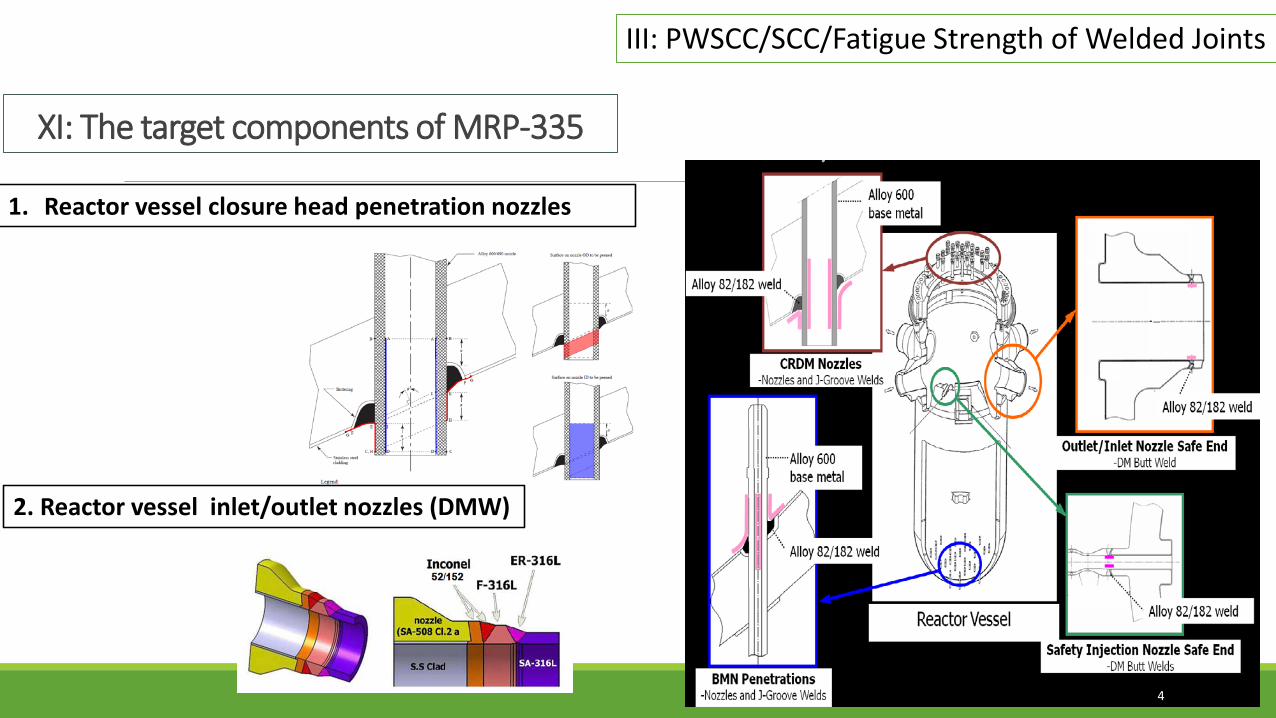
1. Reactor vessel closure head penetration nozzles
4
XI: The target components of MRP-335
2. Reactor vessel inlet/outlet nozzles (DMW)
III: PWSCC/SCC/Fatigue Strength of Welded Joints

UNSM as an SSI for ASME Section III – Task Group on Weld Residual Stress (WRS) for New Plant components
5
NB/ND/NG-4422 Peening(4421: Backing Rings)NC-4423.3 Peening (4423.3: Double Welded Joints, Single-Welded Joints)
6
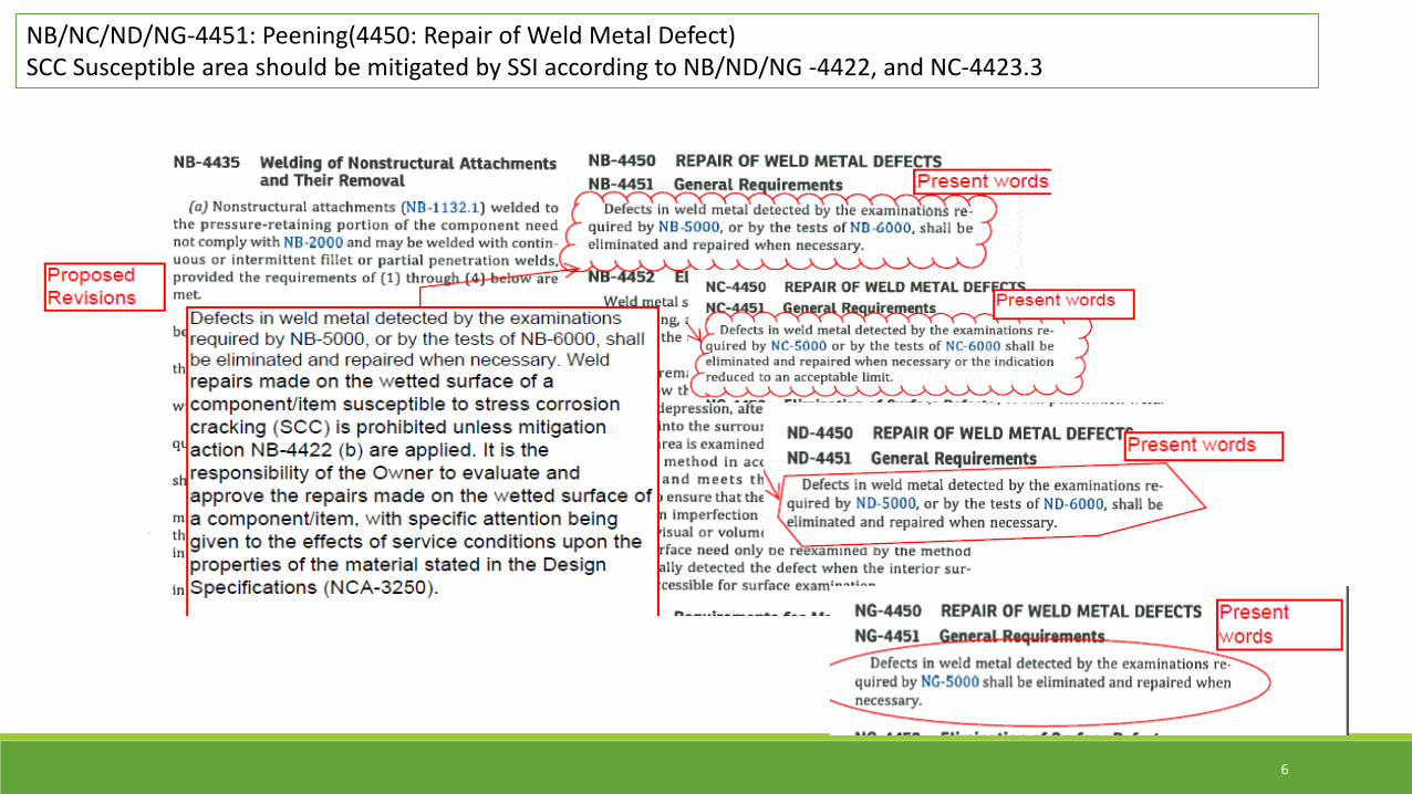
NB/NC/ND/NG-4451: Peening(4450: Repair of Weld Metal Defect)SCC Susceptible area should be mitigated by SSI according to NB/ND/NG -4422, and NC-4423.3
7
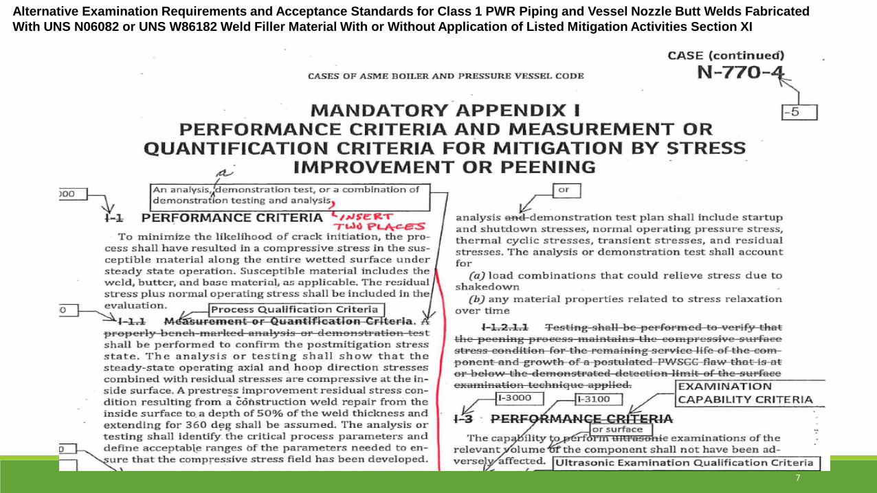
Alternative Examination Requirements and Acceptance Standards for Class 1 PWR Piping and Vessel Nozzle Butt Welds Fabricated With UNS N06082 or UNS W86182 Weld Filler Material With or Without Application of Listed Mitigation Activities Section XI

Topical Report for Primary Water Stress Corrosion Cracking Mitigation by Surface Stress Improvement (MRP-335, Revision 3-A)
To define appropriate inspection requirements and intervals for Alloy 600 reactorpressure vessel head penetration nozzles and Alloy 82/182 dissimilar metal welds inprimary system piping treated by SSI methods to mitigate primary water stress corrosioncracking (PWSCC). These requirements apply in case relaxation of the applicableinspection requirements for unmitigated components is sought.
It is important to note that the requirements of this report are generally not applicablewhere peening is performed for asset management without request for inspection relief.
EPRI Project Manager: P. CrookerDominion Engineering, Inc.G. White/J. Gorman/K. Schmitt/K. Fuhr/M. Burkardt: PIThis report describes research sponsored by EPRI.
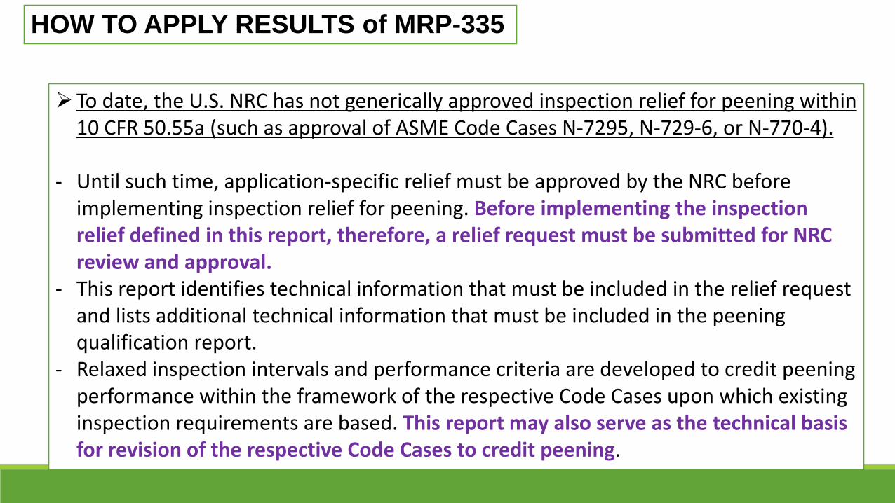
To date, the U.S. NRC has not generically approved inspection relief for peening within 10 CFR 50.55a (such as approval of ASME Code Cases N-7295, N-729-6, or N-770-4).
- Until such time, application-specific relief must be approved by the NRC before implementing inspection relief for peening. Before implementing the inspection relief defined in this report, therefore, a relief request must be submitted for NRC review and approval.
- This report identifies technical information that must be included in the relief request and lists additional technical information that must be included in the peening qualification report.
- Relaxed inspection intervals and performance criteria are developed to credit peening performance within the framework of the respective Code Cases upon which existing inspection requirements are based. This report may also serve as the technical basis for revision of the respective Code Cases to credit peening.
HOW TO APPLY RESULTS of MRP-335
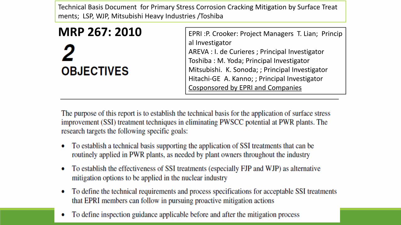
MRP 267: 2010 EPRI :P. Crooker: Project Managers T. Lian; Principal InvestigatorAREVA : I. de Curieres ; Principal InvestigatorToshiba : M. Yoda; Principal InvestigatorMitsubishi. K. Sonoda; ; Principal InvestigatorHitachi-GE A. Kanno; ; Principal InvestigatorCosponsored by EPRI and Companies
Technical Basis Document for Primary Stress Corrosion Cracking Mitigation by Surface Treatments; LSP, WJP, Mitsubishi Heavy Industries /Toshiba
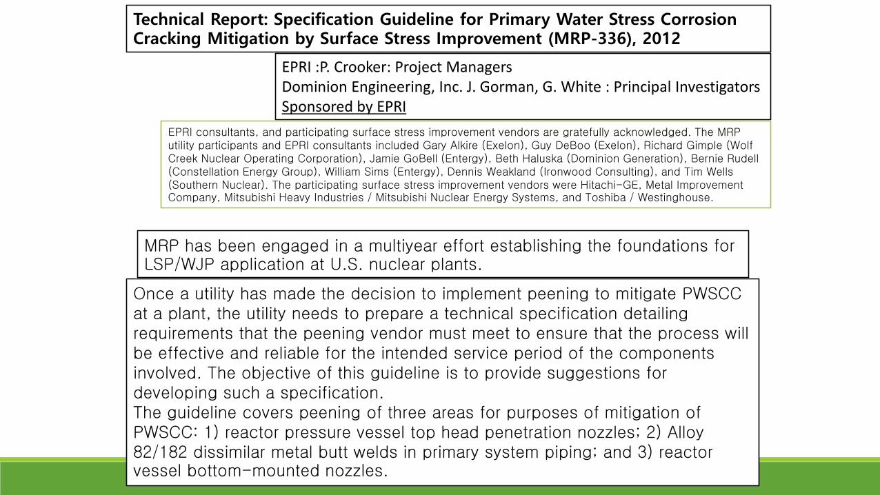
Technical Report: Specification Guideline for Primary Water Stress Corrosion Cracking Mitigation by Surface Stress Improvement (MRP-336), 2012
EPRI :P. Crooker: Project Managers Dominion Engineering, Inc. J. Gorman, G. White : Principal InvestigatorsSponsored by EPRI
MRP has been engaged in a multiyear effort establishing the foundations for LSP/WJP application at U.S. nuclear plants.
Once a utility has made the decision to implement peening to mitigate PWSCC at a plant, the utility needs to prepare a technical specification detailing requirements that the peening vendor must meet to ensure that the process will be effective and reliable for the intended service period of the components involved. The objective of this guideline is to provide suggestions for developing such a specification.The guideline covers peening of three areas for purposes of mitigation of PWSCC: 1) reactor pressure vessel top head penetration nozzles; 2) Alloy 82/182 dissimilar metal butt welds in primary system piping; and 3) reactor vessel bottom-mounted nozzles.
EPRI consultants, and participating surface stress improvement vendors are gratefully acknowledged. The MRP utility participants and EPRI consultants included Gary Alkire (Exelon), Guy DeBoo (Exelon), Richard Gimple (Wolf Creek Nuclear Operating Corporation), Jamie GoBell (Entergy), Beth Haluska (Dominion Generation), Bernie Rudell(Constellation Energy Group), William Sims (Entergy), Dennis Weakland (Ironwood Consulting), and Tim Wells (Southern Nuclear). The participating surface stress improvement vendors were Hitachi-GE, Metal Improvement Company, Mitsubishi Heavy Industries / Mitsubishi Nuclear Energy Systems, and Toshiba / Westinghouse.
II. Meeting the Requirement of III and XI by an alternative Surface Stress Improvement Technology “UNSM (Ultrasonic Nanocrystal Surface Modification)”
1. UNSM Technology, Capabilities and Industrial Applications2. UNSM for PWSCC; ASME 2017 PVP2017-65338, 65436
13
1. UNSM Technology, Capabilities and Industrial Applications
14

Fine or Micro Shot Peening (FMSP)
Ultrasonic Shot Peening (USP)SMAT
Low Plasticity Burnishing (LPB)
Laser Shot Peening (LSP)
www.surfaceenhancement.comhttp://www.lambdatechs.com/
www.lspt.comwww.metalimprovement.com
//www.toshiba.co.jp/nuclearenergy
www.sonats.com
www. fujiwpc.co.jp
Ultrasonic Nanocrystal Surface Modification(UNSM) imst.sunmoon.ac.kr/www.deignmecha.co.kr
Novel Surface Modification Technologies
Water Jet Peening/Cavitation Peeningwww.mhi.co.jp/ ww.mm.mech.tohoku.ac.jp
ST
USP
MSP
Cavitation Peening
UNSM
LPB
LSP
15
Forge (Human) Forge ( Machine)
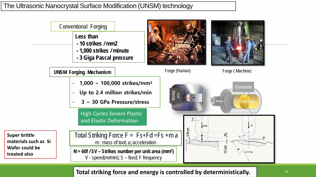
The Ultrasonic Nanocrystal Surface Modification (UNSM) technology
Conventional ForgingLess than - 10 strikes / mm2- 1,000 strikes / minute- 3 Giga Pascal pressure
N = 60f / SV – Strikes number per unit area (mm2)V - speed(m/min); S – feed; f- frequency
Total Striking Force F = Fs+Fd =Fs +m am : mass of tool; a;:acceleration
Generator
피가
공물
피가
공물 W
orkp
iec
e
UNSM Forging Mechanism
- 1,000 ~ 100,000 strikes/mm2
- Up to 2.4 million strikes/min
- 3 ~ 30 GPa Pressure/stress
High Cycles Severe Plastic and Elastic Deformation
Total striking force and energy is controlled by deterministically.
Super brittle materials such as Si Wafer could be treated also
16
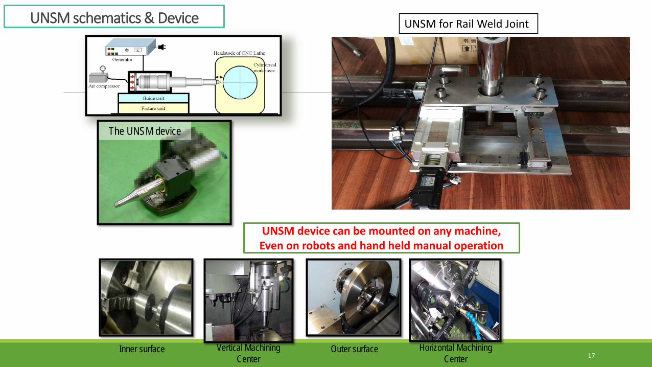
UNSM schematics & Device
The UNSM device
Outer surfaceInner surface Horizontal Machining Center
Vertical Machining Center
UNSM device can be mounted on any machine,Even on robots and hand held manual operation
UNSM for Rail Weld Joint
17
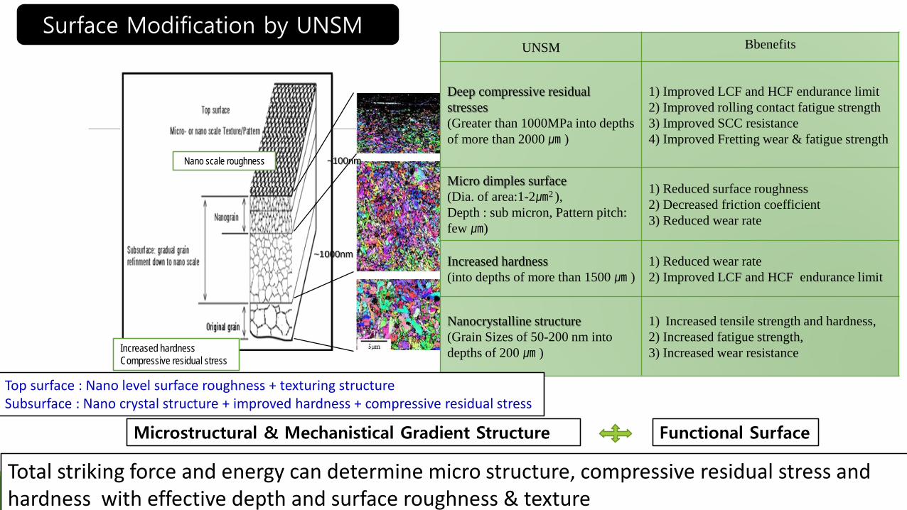
Nano scale roughness
Increased hardnessCompressive residual stress
Surface Modification by UNSMUNSM Bbenefits
Deep compressive residualstresses (Greater than 1000MPa into depths of more than 2000 ㎛ )
1) Improved LCF and HCF endurance limit2) Improved rolling contact fatigue strength3) Improved SCC resistance4) Improved Fretting wear & fatigue strength
Micro dimples surface (Dia. of area:1-2㎛2 ), Depth : sub micron, Pattern pitch: few ㎛)
1) Reduced surface roughness2) Decreased friction coefficient3) Reduced wear rate
Increased hardness (into depths of more than 1500 ㎛ )
1) Reduced wear rate2) Improved LCF and HCF endurance limit
Nanocrystalline structure (Grain Sizes of 50-200 nm into depths of 200 ㎛ )
1) Increased tensile strength and hardness,2) Increased fatigue strength,3) Increased wear resistance
Top surface : Nano level surface roughness + texturing structureSubsurface : Nano crystal structure + improved hardness + compressive residual stress
~100nm
~1000nm
Microstructural & Mechanistical Gradient Structure Functional Surface
Total striking force and energy can determine micro structure, compressive residual stress and hardness with effective depth and surface roughness & texture
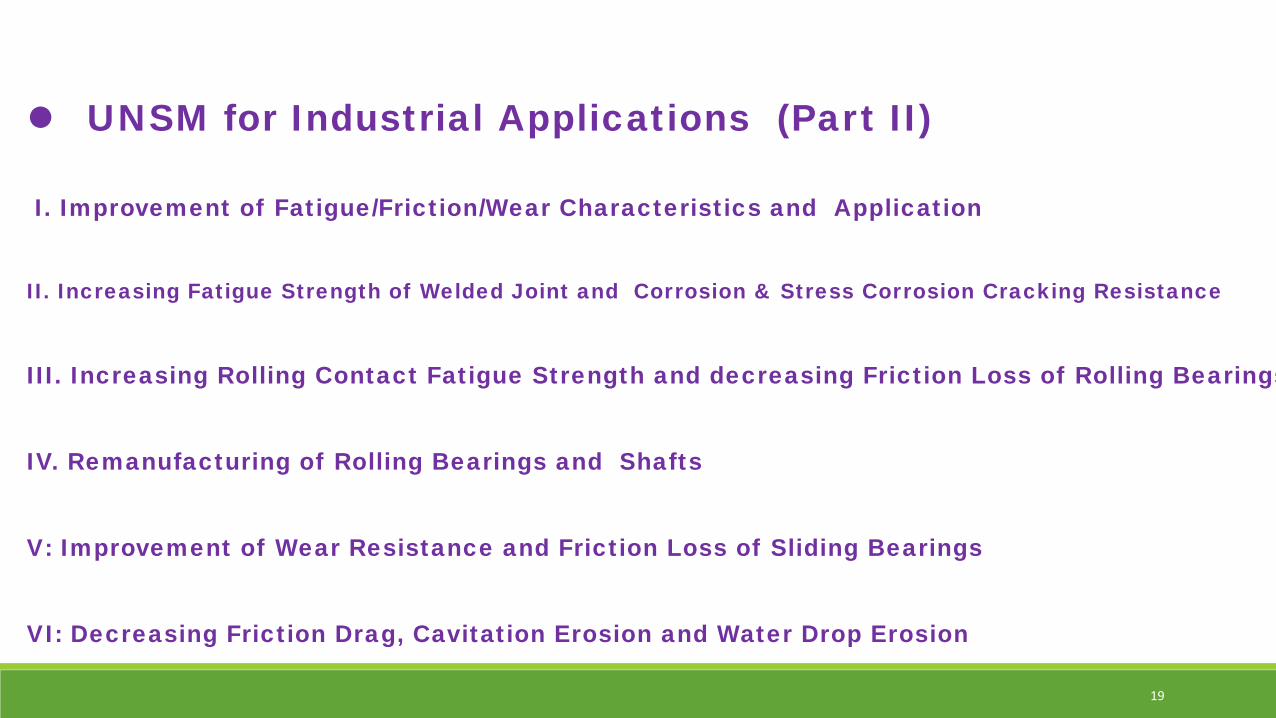
UNSM for Industrial Applications (Part II)
I. Improvement of Fatigue/Friction/Wear Characteristics and Application
II. Increasing Fatigue Strength of Welded Joint and Corrosion & Stress Corrosion Cracking Resistance
III. Increasing Rolling Contact Fatigue Strength and decreasing Friction Loss of Rolling Bearings
IV. Remanufacturing of Rolling Bearings and Shafts
V: Improvement of Wear Resistance and Friction Loss of Sliding Bearings
VI: Decreasing Friction Drag, Cavitation Erosion and Water Drop Erosion
19

Industrial Knife Rolling and Sliding Bearings
20
Proven Solution in Industry of 3 Nations and in Academy with more than 330 publication since 2000

Mitigation PWSCC by Ultrasonic Nanocrystal Surface Modification (UNSM) technology
International Light Water Reactor Materials Reliability Conference and Exhibition 2016
2015~2017: KOREA – USA Project for International Nuclear Energy Research Initiative (I-NERI)
Vijay K. Vasudevan (PI), A..Gill ,, D. Tamman, Seetha R. Mannava ,
Abhishek Telanga Dong Qian b,Sebastien Teysseyre, c
a U. Cincinnati, b U. Texas,c Idaho National Lab. in USA.
Young-Sik Pyun(PI), Auezhan Amanov, Hak-Doo Kim, Jun-
Hyong Kim,1 Young-Sik Kim 2. Y. S. Choi 3, H.S. Cho 4
1 SunMoon U., Andong U.,3 Pusan U., 4 KPS in Korea
Professor of Mechanical & ICT Convergence Engineering, Sun Moon UniversityDirector of Institute for Manufacturing Systems Technology &Chungnam Remanufacturing Innovation Center010-5423-2333, [email protected]
Founder and CTO, DesignMecha Co., Ltd.
2016-08-03Young Sik Pyun
21
2. UNSM for PWSCC; ASME 2017 PVP2017-65338, 65436
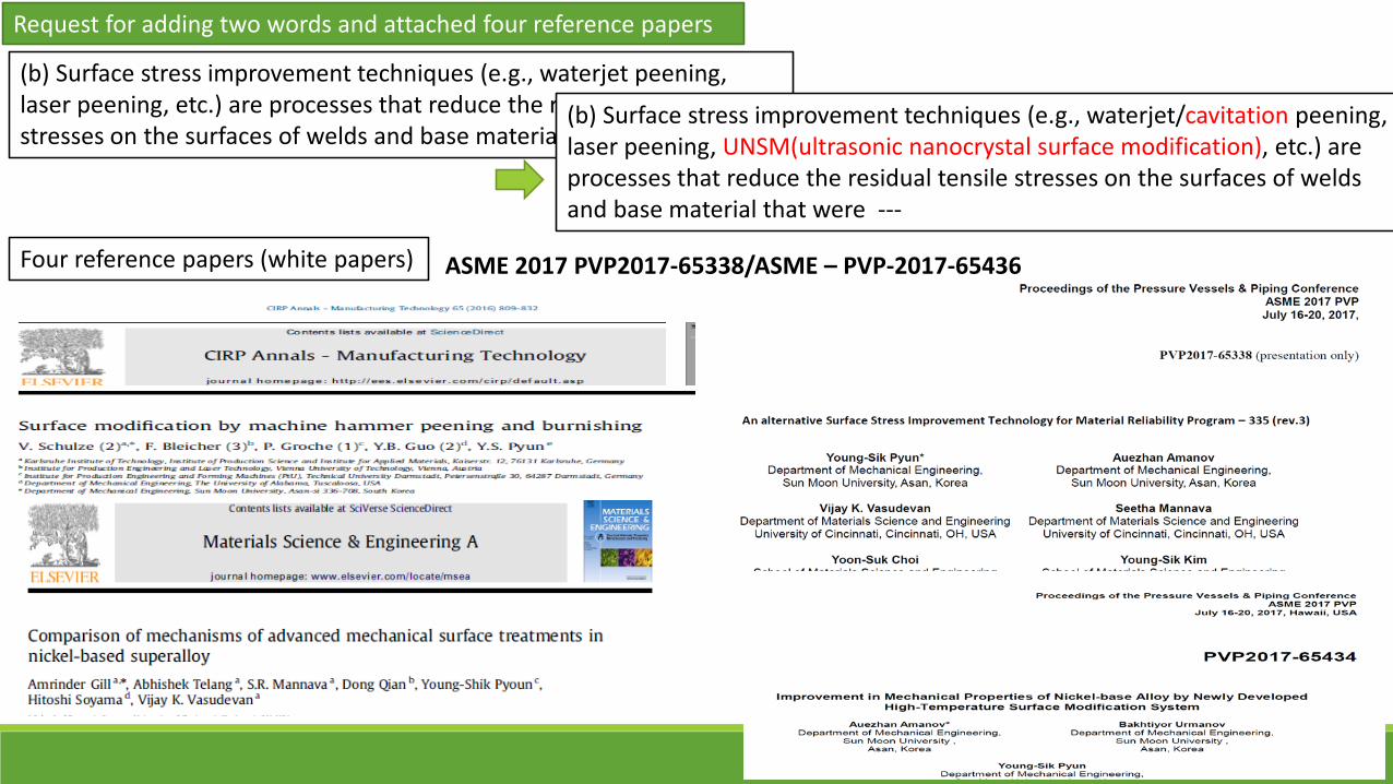
(b) Surface stress improvement techniques (e.g., waterjet peening, laser peening, etc.) are processes that reduce the residual tensile stresses on the surfaces of welds and base material that were ---
(b) Surface stress improvement techniques (e.g., waterjet/cavitation peening, laser peening, UNSM(ultrasonic nanocrystal surface modification), etc.) are processes that reduce the residual tensile stresses on the surfaces of welds and base material that were ---
Request for adding two words and attached four reference papers
Four reference papers (white papers)
22
ASME 2017 PVP2017-65338/ASME – PVP-2017-65436
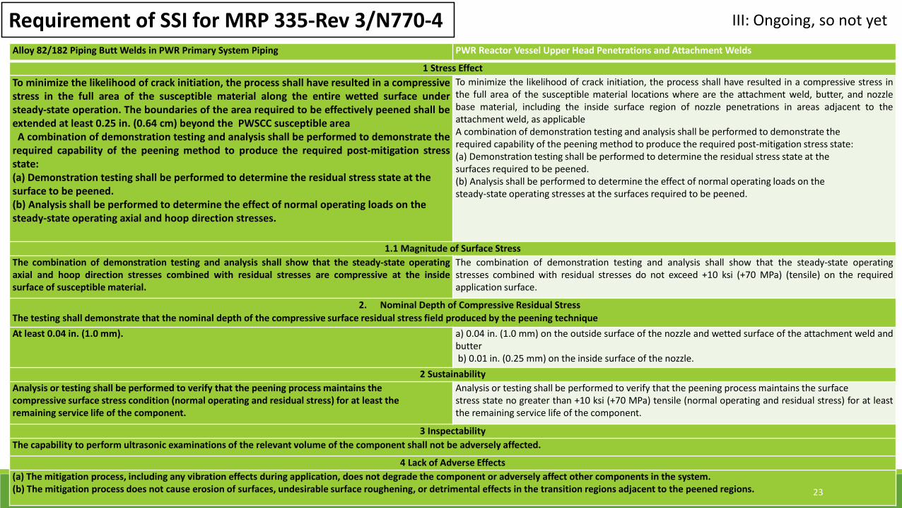
Requirement of SSI for MRP 335-Rev 3/N770-4Alloy 82/182 Piping Butt Welds in PWR Primary System Piping PWR Reactor Vessel Upper Head Penetrations and Attachment Welds
1 Stress EffectTo minimize the likelihood of crack initiation, the process shall have resulted in a compressivestress in the full area of the susceptible material along the entire wetted surface understeady-state operation. The boundaries of the area required to be effectively peened shall beextended at least 0.25 in. (0.64 cm) beyond the PWSCC susceptible area
A combination of demonstration testing and analysis shall be performed to demonstrate therequired capability of the peening method to produce the required post-mitigation stressstate:(a) Demonstration testing shall be performed to determine the residual stress state at thesurface to be peened.(b) Analysis shall be performed to determine the effect of normal operating loads on thesteady-state operating axial and hoop direction stresses.
To minimize the likelihood of crack initiation, the process shall have resulted in a compressive stress inthe full area of the susceptible material locations where are the attachment weld, butter, and nozzlebase material, including the inside surface region of nozzle penetrations in areas adjacent to theattachment weld, as applicableA combination of demonstration testing and analysis shall be performed to demonstrate therequired capability of the peening method to produce the required post-mitigation stress state:(a) Demonstration testing shall be performed to determine the residual stress state at thesurfaces required to be peened.(b) Analysis shall be performed to determine the effect of normal operating loads on thesteady-state operating stresses at the surfaces required to be peened.
1.1 Magnitude of Surface StressThe combination of demonstration testing and analysis shall show that the steady-state operatingaxial and hoop direction stresses combined with residual stresses are compressive at the insidesurface of susceptible material.
The combination of demonstration testing and analysis shall show that the steady-state operatingstresses combined with residual stresses do not exceed +10 ksi (+70 MPa) (tensile) on the requiredapplication surface.
2. Nominal Depth of Compressive Residual StressThe testing shall demonstrate that the nominal depth of the compressive surface residual stress field produced by the peening techniqueAt least 0.04 in. (1.0 mm). a) 0.04 in. (1.0 mm) on the outside surface of the nozzle and wetted surface of the attachment weld and
butterb) 0.01 in. (0.25 mm) on the inside surface of the nozzle.
2 SustainabilityAnalysis or testing shall be performed to verify that the peening process maintains thecompressive surface stress condition (normal operating and residual stress) for at least theremaining service life of the component.
Analysis or testing shall be performed to verify that the peening process maintains the surfacestress state no greater than +10 ksi (+70 MPa) tensile (normal operating and residual stress) for at leastthe remaining service life of the component.
3 InspectabilityThe capability to perform ultrasonic examinations of the relevant volume of the component shall not be adversely affected.
4 Lack of Adverse Effects(a) The mitigation process, including any vibration effects during application, does not degrade the component or adversely affect other components in the system.(b) The mitigation process does not cause erosion of surfaces, undesirable surface roughening, or detrimental effects in the transition regions adjacent to the peened regions. 23
III: Ongoing, so not yet
24
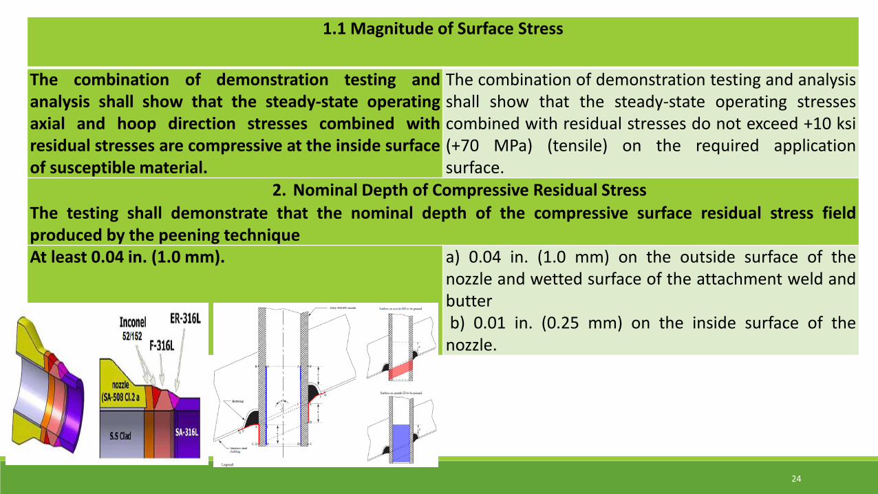
1.1 Magnitude of Surface Stress
The combination of demonstration testing andanalysis shall show that the steady-state operatingaxial and hoop direction stresses combined withresidual stresses are compressive at the inside surfaceof susceptible material.
The combination of demonstration testing and analysisshall show that the steady-state operating stressescombined with residual stresses do not exceed +10 ksi(+70 MPa) (tensile) on the required applicationsurface.
2. Nominal Depth of Compressive Residual StressThe testing shall demonstrate that the nominal depth of the compressive surface residual stress fieldproduced by the peening techniqueAt least 0.04 in. (1.0 mm). a) 0.04 in. (1.0 mm) on the outside surface of the
nozzle and wetted surface of the attachment weld andbutterb) 0.01 in. (0.25 mm) on the inside surface of the
nozzle.
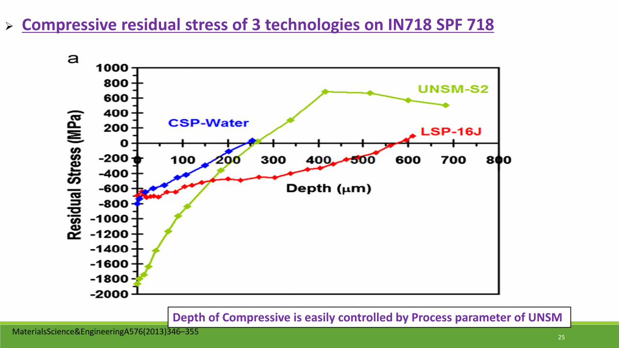
Compressive residual stress of 3 technologies on IN718 SPF 718
MaterialsScience&EngineeringA576(2013)346–35525
Depth of Compressive is easily controlled by Process parameter of UNSM

26
Case A B C DAmplitude(μm) 40 40 60 60Static Load(N) 40 60 40 60
Rigaku Ultima IV,Cu Kα radiation
Case A Case B Case C Case DResidual Stress at 1 mm depth -134.04 -194.75 -223.42 -249.23
Top surface : -1,020 ~ -1,231 MPa after UNSM (Before± 100 MPa)
Compressive Residual Stress of IN 600 at 1 mm depth after UNSM treatment
Process Parameter of UNSM
Inside of Inlet & outlet: same as as above Inside of CRDM nozzle: more than 500 MPa and 0.3mm
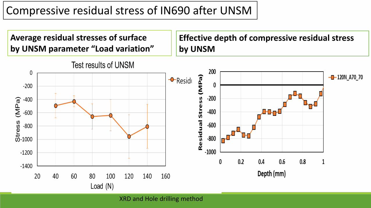
Average residual stresses of surface by UNSM parameter “Load variation”
Compressive residual stress of IN690 after UNSM
Effective depth of compressive residual stress by UNSM
XRD and Hole drilling method
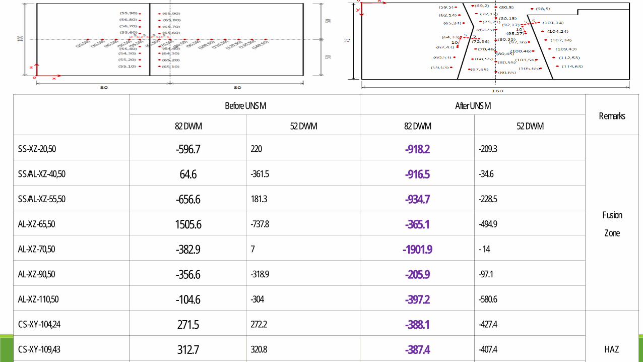
Before UNSM After UNSMRemarks
82 DWM 52 DWM 82 DWM 52 DWM
SS-XZ-20,50 -596.7 220 -918.2 -209.3
Fusion
Zone
SS/AL-XZ-40,50 64.6 -361.5 -916.5 -34.6
SS/AL-XZ-55,50 -656.6 181.3 -934.7 -228.5
AL-XZ-65,50 1505.6 -737.8 -365.1 -494.9
AL-XZ-70,50 -382.9 7 -1901.9 -14
AL-XZ-90,50 -356.6 -318.9 -205.9 -97.1
AL-XZ-110,50 -104.6 -304 -397.2 -580.6
CS-XY-104,24 271.5 272.2 -388.1 -427.4
HAZCS-XY-109,43 312.7 320.8 -387.4 -407.4

29
2 SustainabilityAnalysis or testing shall be performed to verify thatthe peening process maintains thecompressive surface stress condition (normaloperating and residual stress) for at least theremaining service life of the component.
Analysis or testing shall be performed to verify thatthe peening process maintains the surfacestress state no greater than +10 ksi (+70 MPa) tensile(normal operating and residual stress) for at least theremaining service life of the component.

Thermal Relaxation of Surface Residual Stress in LSP, UNSM, CSP-Treated IN718 SPF
550°C
Stress relaxes quickly within the first five minutes, then attains a stable value at longer times. Stability is very good at 550°C and 600°C, with the extent of relaxation varying somewhat with process. LSP and CSP behavior is similar. UNSM also maintains remarkably good stability. Extent of relaxation greater at 650°C, with all three processes converging to a more or less constant stress value at longer times
600°C 650°C
31
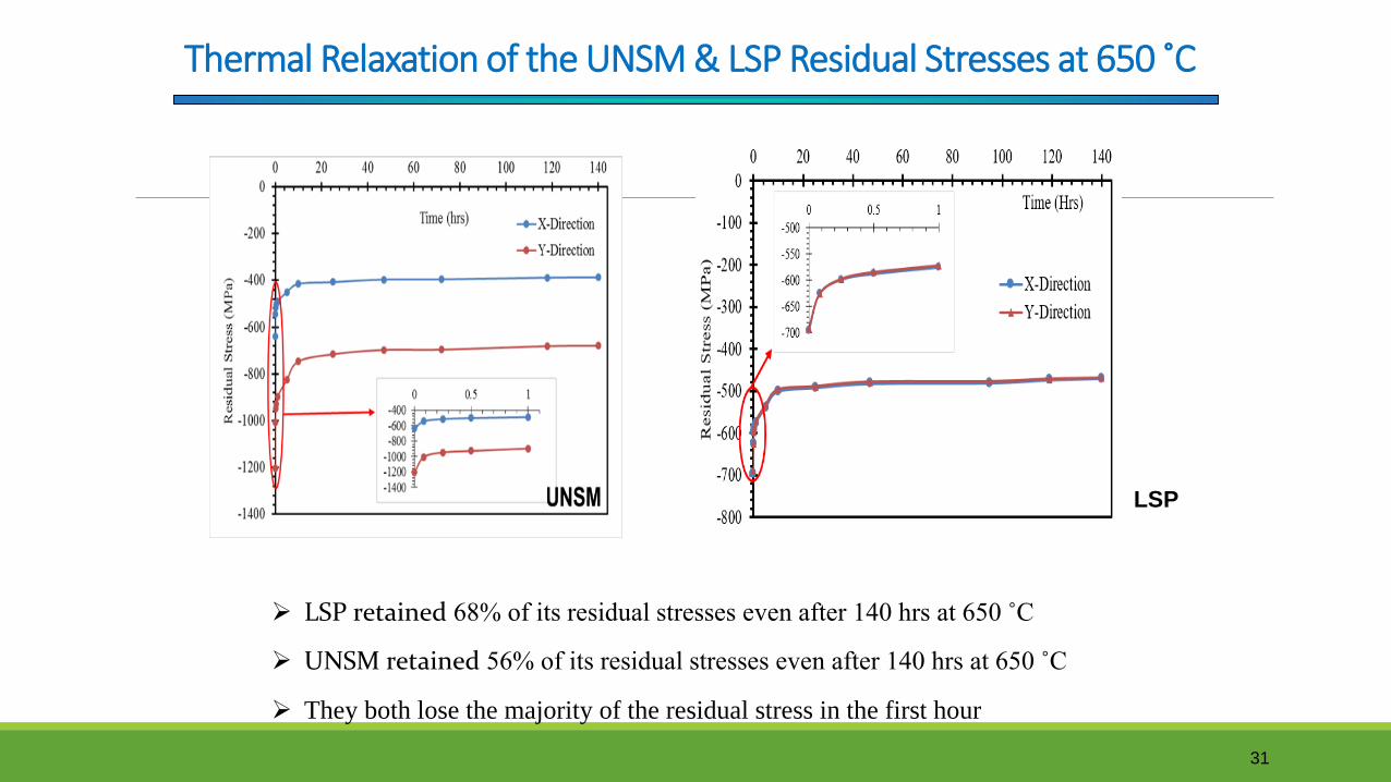
Thermal Relaxation of the UNSM & LSP Residual Stresses at 650 ˚C
LSP retained 68% of its residual stresses even after 140 hrs at 650 ˚C
UNSM retained 56% of its residual stresses even after 140 hrs at 650 ˚C
They both lose the majority of the residual stress in the first hour
LSP

32
3 InspectabilityThe capability to perform ultrasonic examinations of the relevant volume ofthe component shall not be adversely affected.
4 Lack of Adverse Effects(a) The mitigation process, including any vibration effects duringapplication, does not degrade the component or adversely affect othercomponents in the system.(b) The mitigation process does not cause erosion of surfaces, undesirablesurface roughening, or detrimental effects in the transition regions adjacentto the peened regions.
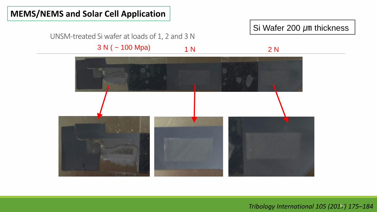
1 N 2 N3 N ( ~ 100 Mpa)UNSM-treated Si wafer at loads of 1, 2 and 3 N
Si Wafer 200 ㎛ thickness MEMS/NEMS and Solar Cell Application
Tribology International 105 (2017) 175–18433
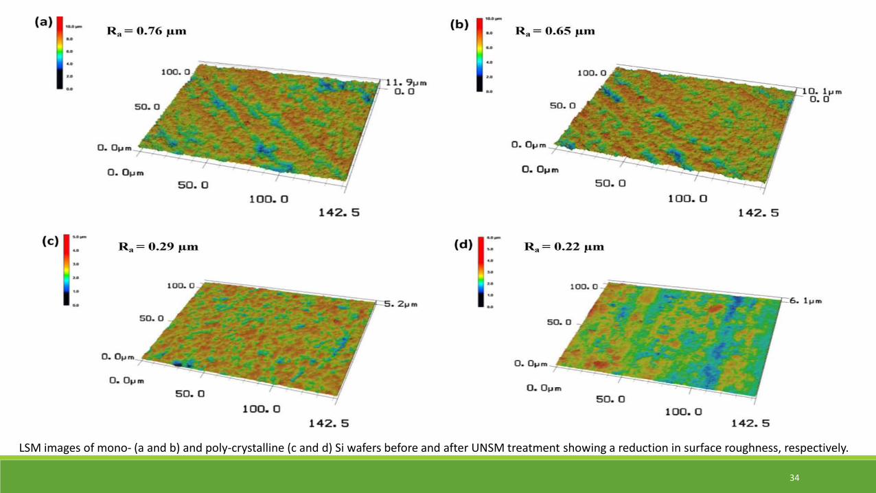
LSM images of mono- (a and b) and poly-crystalline (c and d) Si wafers before and after UNSM treatment showing a reduction in surface roughness, respectively.
34
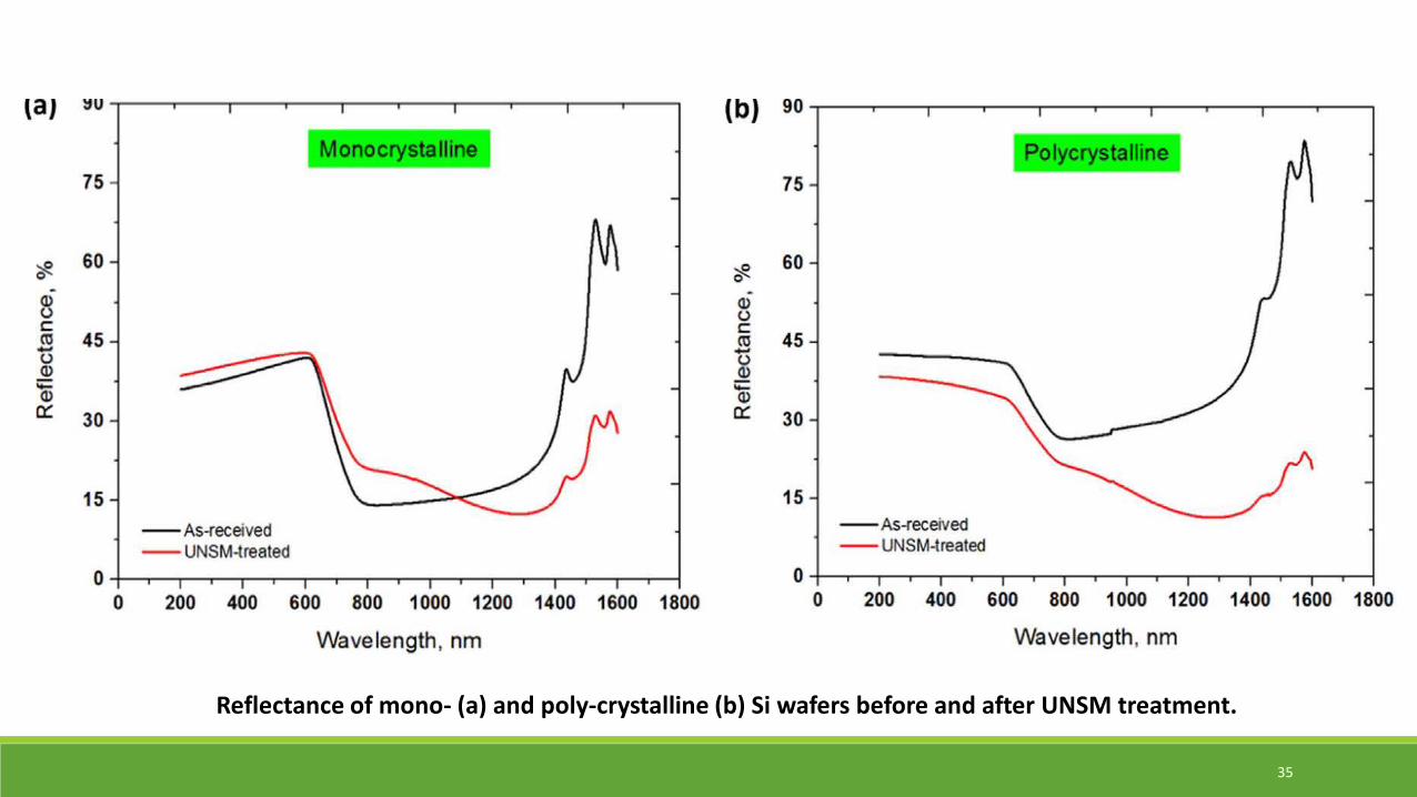
Reflectance of mono- (a) and poly-crystalline (b) Si wafers before and after UNSM treatment.
35
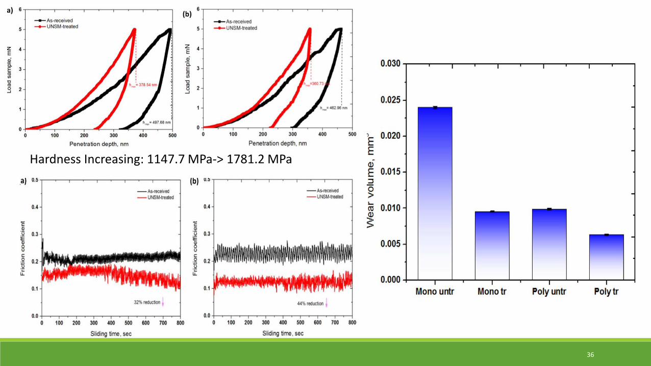
Hardness Increasing: 1147.7 MPa-> 1781.2 MPa
36

Anodic Polarization Test
Sodium sulfate (Na2S2O3) 0.1M)
37
Corrosion Properties of 316L/Alloy 82 before and after UNSMIntergranular Corrosion Rate Heuy test- ASTM A 262 Practice C,Boiling 65% Nitric acid (HNO3)-
(1) ASTM A 262 Practice A, (2) Double-Loop Electropotentiokinetic Reactivation
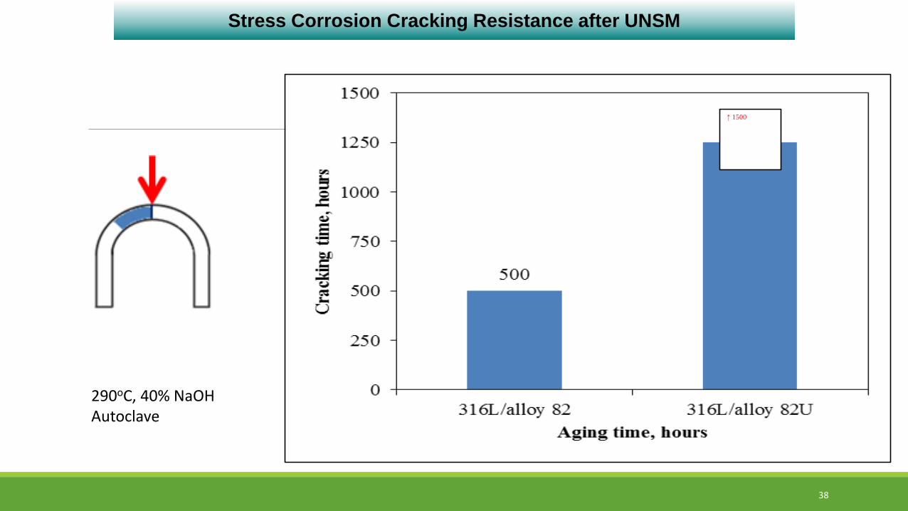
↑ 1500
Stress Corrosion Cracking Resistance after UNSM
38
290oC, 40% NaOHAutoclave

UC results for SCC on 600
Surface grain boundary engineering of Alloy 600 for improved resistance to stress corrosion cracking : A.Telang etal./MaterialsScience&EngineeringA648(2015)280–288 39

A Surface Stress Improvement technology
“UNSM (Ultrasonic Nanocrystal Surface Modification)”
An easy and simple technology,
but the bigger and deeper compressive stress than other SSI
and eliminating micro defects in fusion and interface of
welding/bonding as like forging but much faster and stronger
40
Better Safety, Longer Operation Better Profits
III. Concluding Remarks
[email protected]@gmail.com
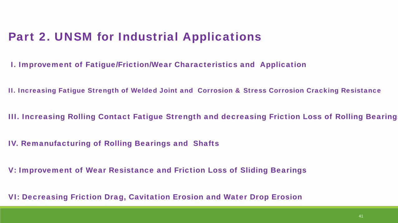
Part 2. UNSM for Industrial Applications
I. Improvement of Fatigue/Friction/Wear Characteristics and Application
II. Increasing Fatigue Strength of Welded Joint and Corrosion & Stress Corrosion Cracking Resistance
III. Increasing Rolling Contact Fatigue Strength and decreasing Friction Loss of Rolling Bearings
IV. Remanufacturing of Rolling Bearings and Shafts
V: Improvement of Wear Resistance and Friction Loss of Sliding Bearings
VI: Decreasing Friction Drag, Cavitation Erosion and Water Drop Erosion
41
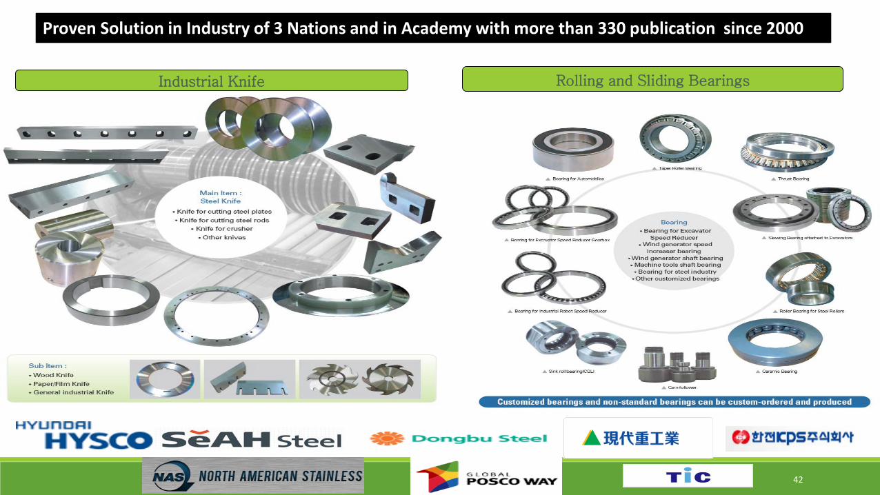
Industrial Knife Rolling and Sliding Bearings
42
Proven Solution in Industry of 3 Nations and in Academy with more than 330 publication since 2000
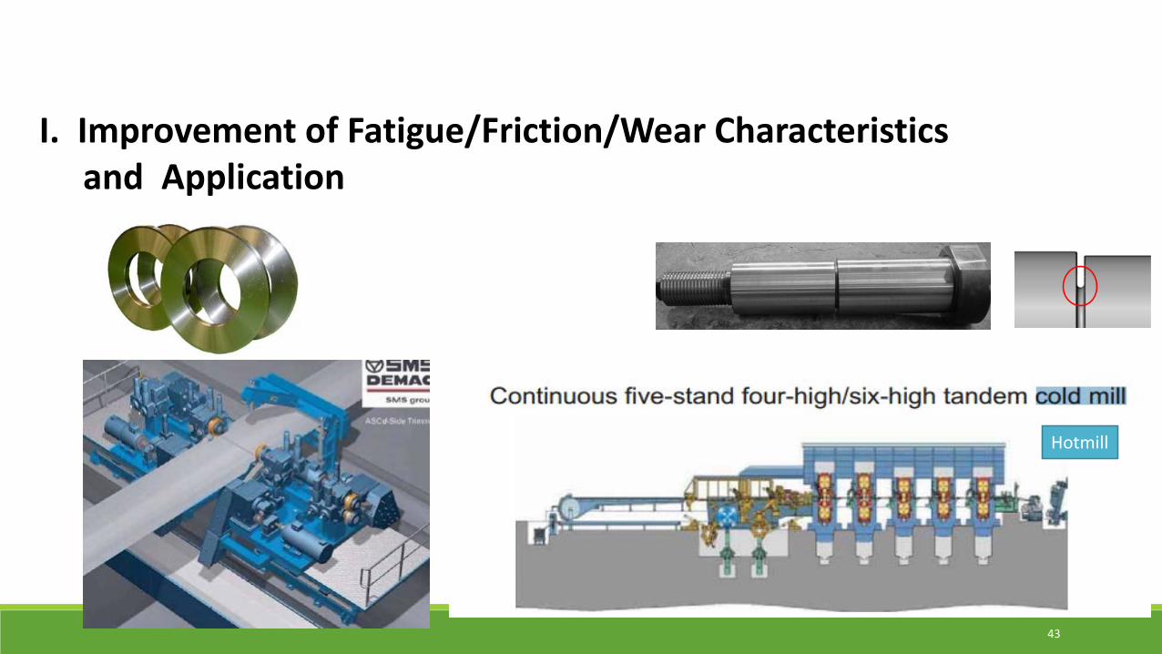
I. Improvement of Fatigue/Friction/Wear Characteristicsand Application
Hotmill
43
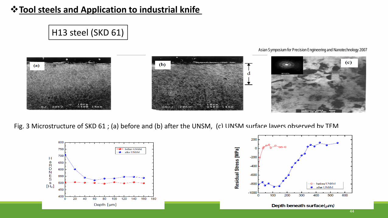
Asian Symposium for Precision Engineering and Nanotechnology 2007
H13 steel (SKD 61)
Fig. 3 Microstructure of SKD 61 ; (a) before and (b) after the UNSM, (c) UNSM surface layers observed by TEM
Tool steels and Application to industrial knife
44

Rotary Bending Fatigue Strength, Fiction and Wear Characteristics by UNSM
45
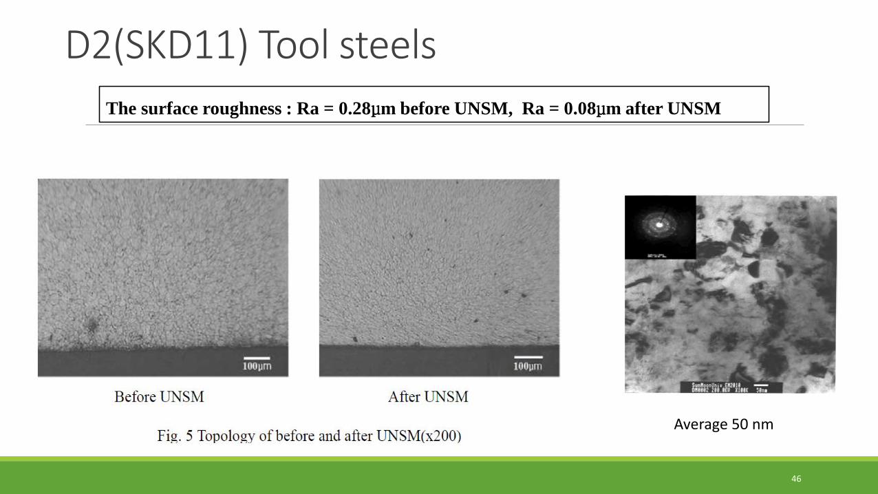
D2(SKD11) Tool steelsAIST 2002
Average 50 nm
The surface roughness : Ra = 0.28μm before UNSM, Ra = 0.08μm after UNSM
46
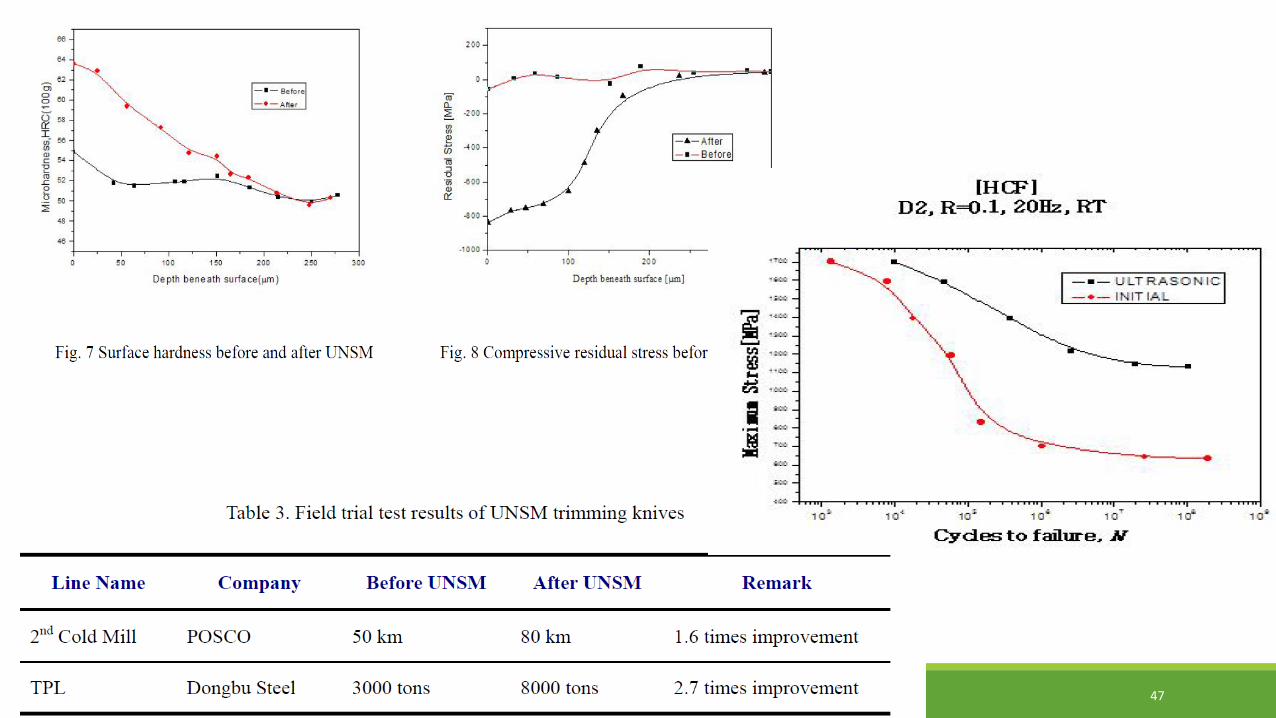
AIST 2002
47

48
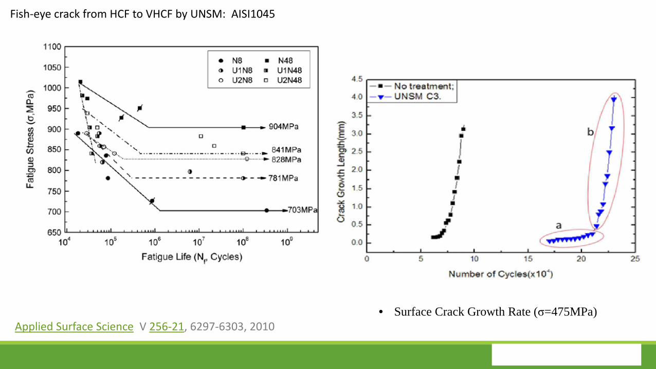
• Surface Crack Growth Rate (σ=475MPa)Applied Surface Science V 256-21, 6297-6303, 2010
Fish-eye crack from HCF to VHCF by UNSM: AISI1045
49
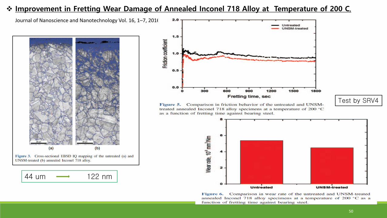
Improvement in Fretting Wear Damage of Annealed Inconel 718 Alloy at Temperature of 200 C,
Journal of Nanoscience and Nanotechnology Vol. 16, 1–7, 2016
44 um 122 nm
Test by SRV4
50
II: Increasing Fatigue Strength of Welded Joint and Corrosion & Stress Corrosion Cracking Resistance
51
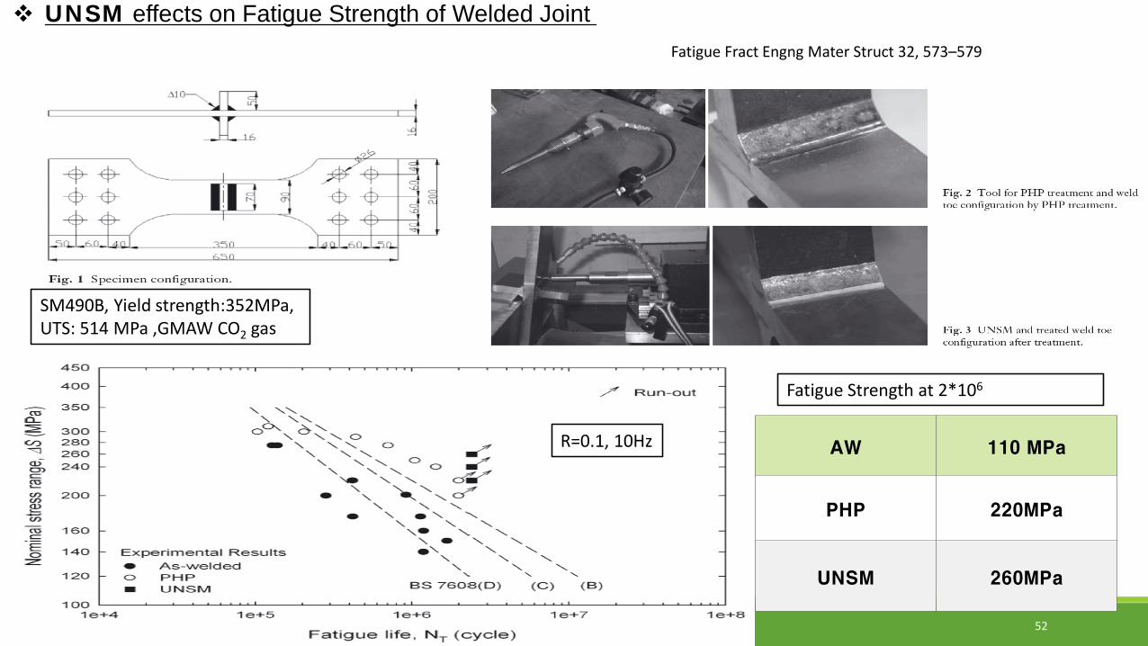
SM490B, Yield strength:352MPa, UTS: 514 MPa ,GMAW CO2 gas
R=0.1, 10Hz AW 110 MPa
PHP 220MPa
UNSM 260MPa
Fatigue Strength at 2*106
Fatigue Fract Engng Mater Struct 32, 573–579
UNSM effects on Fatigue Strength of Welded Joint
52

Hydrogen embrittlement equipment
Pyun, etal.KSME-AB.2015.39.0.000
Rotary Bending Fatigue Tester
700 MPa – 10 times more fatigue cycles 600 MPa – 20 times more fatigue cycles
53
UNSM Effects on Fatigue Strength of Hydrogen Embrittled 718
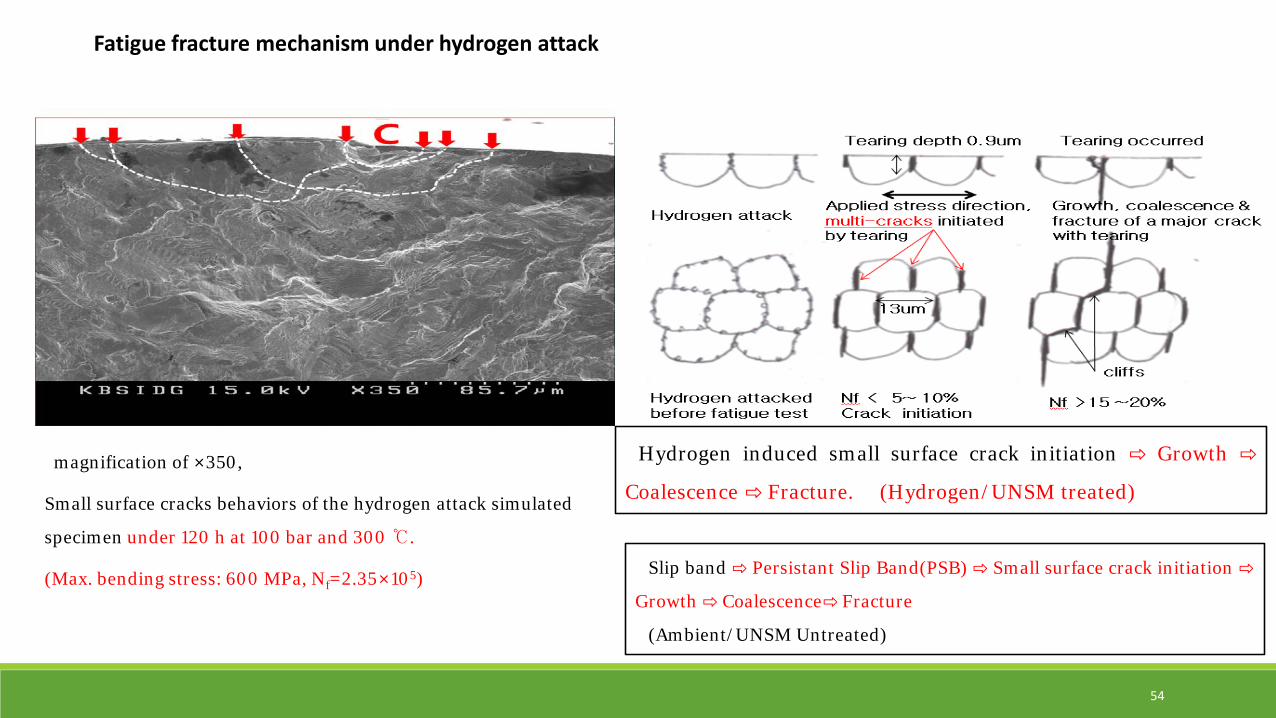
Fatigue fracture mechanism under hydrogen attack
magnification of ×350,
Small surface cracks behaviors of the hydrogen attack simulated
specimen under 120 h at 100 bar and 300℃.
(Max. bending stress: 600 MPa, Nf=2.35×10⁵)
Hydrogen induced small surface crack initiation ⇨ Growth ⇨
Coalescence ⇨ Fracture. (Hydrogen/UNSM treated)
Slip band ⇨ Persistant Slip Band(PSB) ⇨ Small surface crack initiation ⇨
Growth ⇨ Coalescence⇨ Fracture
(Ambient/UNSM Untreated)
54
III. Increasing Rolling Contact Fatigue Strength
and decreasing Friction Loss of Rolling Bearings
55
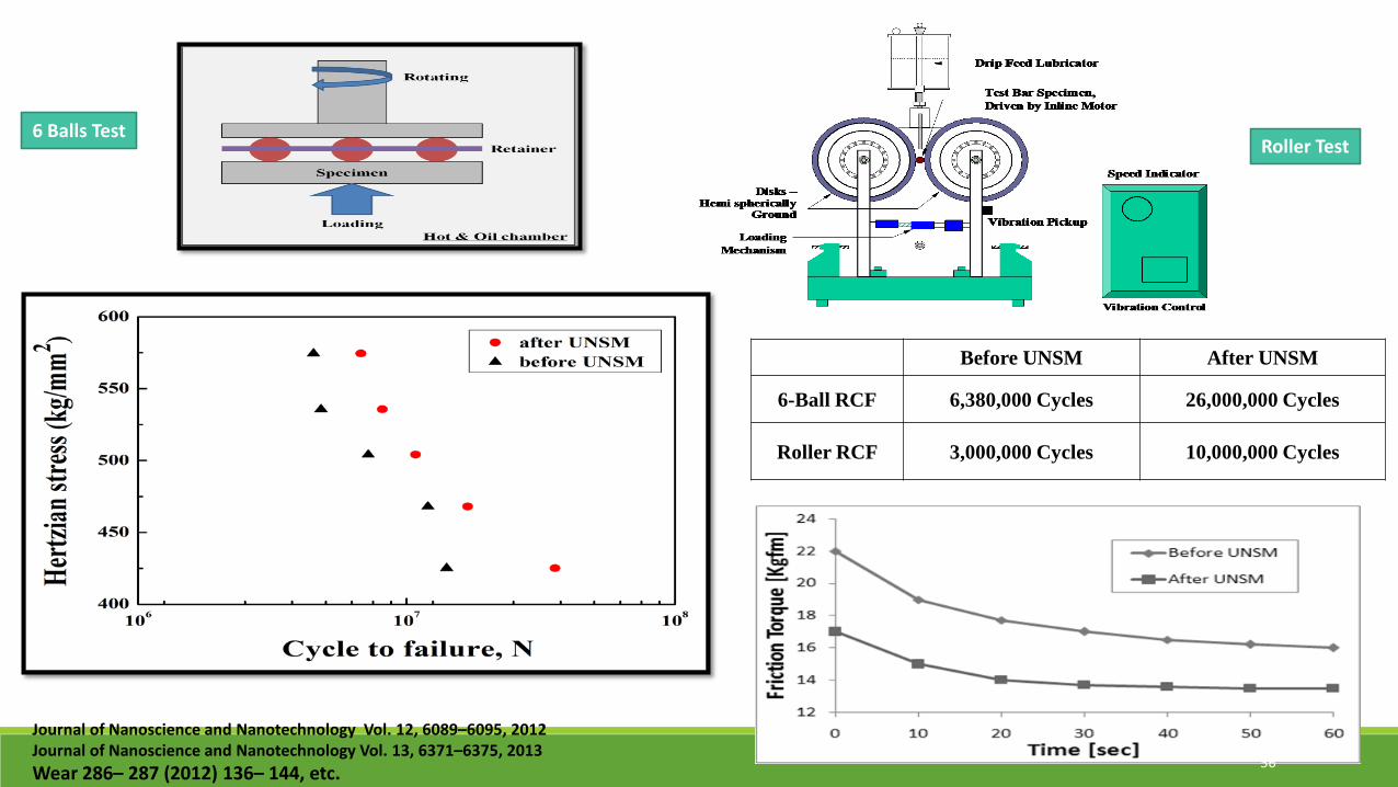
6 Balls TestRoller Test
Before UNSM After UNSM
6-Ball RCF 6,380,000 Cycles 26,000,000 Cycles
Roller RCF 3,000,000 Cycles 10,000,000 Cycles
Journal of Nanoscience and Nanotechnology Vol. 12, 6089–6095, 2012Journal of Nanoscience and Nanotechnology Vol. 13, 6371–6375, 2013Wear 286– 287 (2012) 136– 144, etc. 56

Restoration of Rolling Contact Fatigue Stress built up in Rolling Bearings by UNSM
Mr. Shirmendagva Darisuren, Mr. Jun-Hyong Kim, Dr. Auezhan AmanovDepartment of Mechanical Engineering, Sun Moon University, Asan, Korea
Professor of Mechanical & ICT Convergence Engineering, Sun Moon UniversityDirector of Institute for Manufacturing Systems Technology &Chungnam Remanufacturing Innovation Center010-5423-2333, [email protected]
Founder and CTO, DesignMecha Co., Ltd.
Young Sik Pyun
AEROMAT 2016 Seattle, USA
IV. Remanufacturing of Rolling Bearings and Shafts
57
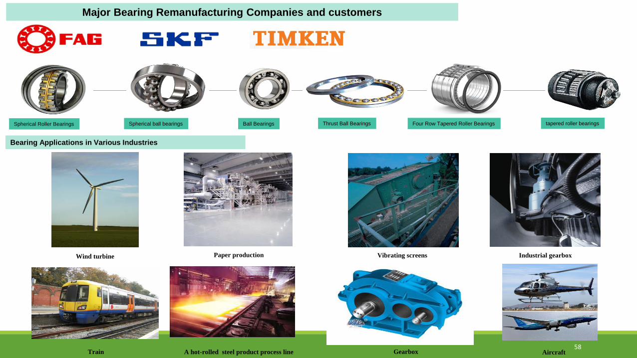
Wind turbine Paper production Vibrating screens Industrial gearbox
Spherical Roller Bearings
A hot-rolled steel product process lineTrain
Spherical ball bearings Ball Bearings Thrust Ball Bearings Four Row Tapered Roller Bearings tapered roller bearings
Major Bearing Remanufacturing Companies and customers
Gearbox Aircraft
Bearing Applications in Various Industries
58
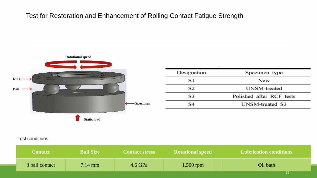
Test for Restoration and Enhancement of Rolling Contact Fatigue Strength
Ring
Ball
Specimen
Rotational speed
Static load
Test conditions
Contact Ball Size Contact stress Rotational speed Lubrication conditions
3 ball contact 7.14 mm 4.6 GPa 1,500 rpm Oil bath59

Rolling Contact Fatigue (RCF) Test Results
Samples Cycles to failure Ratio
1. New specimens 4,641,000 100.0%
2. UNSM treated on new specimens 10,119,000 218.0%
3. Polished after RCF test with 4,000,000 cycles 2,340,000 49.6%
4. UNSM treatment on the #3 specimens 8,323,000 179.3%
Restoration and Enhancement of Rolling Contact Fatigue Strength
60

Restoration and Enhancement of Rotary Bending Fatigue Strength
61
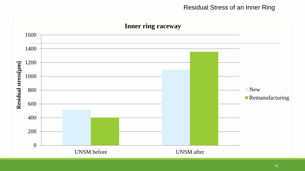
Residual Stress of an Inner Ring
0
200
400
600
800
1000
1200
1400
1600
UNSM before UNSM after
Res
idua
l str
ess[
µm]
Inner ring raceway
NewRemanufacturing
62
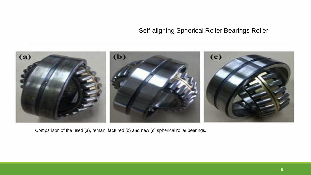
Self-aligning Spherical Roller Bearings Roller
Comparison of the used (a), remanufactured (b) and new (c) spherical roller bearings.
63
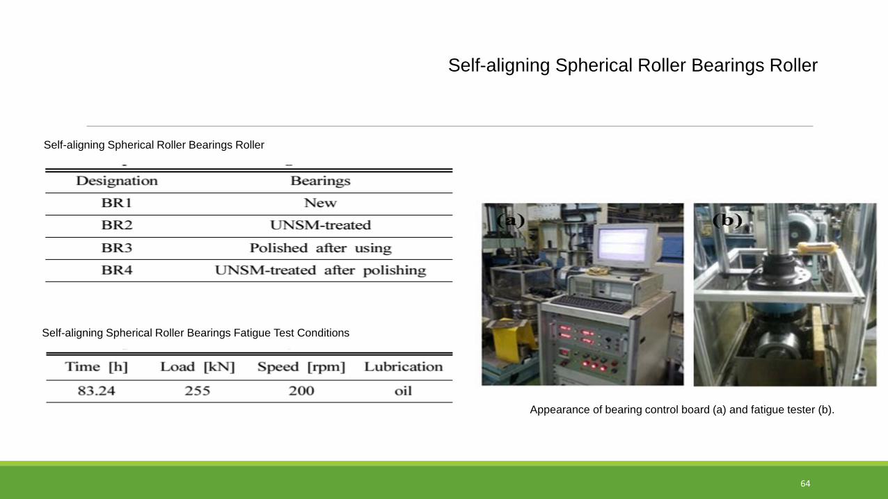
Self-aligning Spherical Roller Bearings Roller
Self-aligning Spherical Roller Bearings Roller
Self-aligning Spherical Roller Bearings Fatigue Test Conditions
Appearance of bearing control board (a) and fatigue tester (b).
64
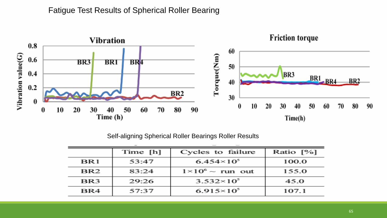
Fatigue Test Results of Spherical Roller Bearing
Self-aligning Spherical Roller Bearings Roller Results
65

V: Improvement of Wear Resistance and Friction Loss of
Sliding Bearings & Bushes
66
67
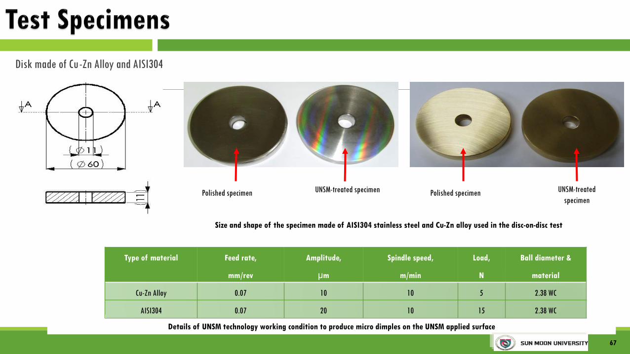
Type of material Feed rate,
mm/rev
Amplitude,
µm
Spindle speed,
m/min
Load,
N
Ball diameter &
material
Cu-Zn Alloy 0.07 10 10 5 2.38 WC
AISI304 0.07 20 10 15 2.38 WC
Size and shape of the specimen made of AISI304 stainless steel and Cu-Zn alloy used in the disc-on-disc test
Polished specimen UNSM-treatedspecimen
Details of UNSM technology working condition to produce micro dimples on the UNSM applied surface
Polished specimen UNSM-treated specimen
67
Disk made of Cu-Zn Alloy and AISI304

68
Disk made of Cu-Zn Alloy and AISI304
Load, N Test Time, min Rotating Speed, rpm Used Oil and Viscosity Oil Temperature, 0C500 10 100-1000 Tonna Oil 32, 0.13 Ns/m2 @ 40 0C 15.4-22
Test conditions
Pressure: 0.18MPa
Surface velocity: 0.314~3.14 m/s
PV value: 0.056~0.56 MPa-m/s
Load
Stationary specimen
Stationary specimen holder
Rotating specimen holder
Oil bath
Stationary shaft
Rotating shaft
Rotating specimen
The friction coefficient has been reduced about 15% after UNSM treatment

Polished surface UNSM-treated surface
Polished surface UNSM-treated surface
Cu-Zn Alloy
69
AISI304
28HRC
55HRC
32HRC
58HRC
10 μm 10 μm
10 μm10 μm

70
Comparison of weight and volume loss of untreated and UNSM-treated specimens
45 % wear reduction
Specimens Untreated UNSM#1 UNSM#2 UNSM#3 UNSM #4 UNSM #5
Weight loss, mg 6.0 5.9 4.2 3.9 3.3 3.3Volume loss, x103 mm3 703 692 492 457 387 387
Specimens Untreated UNSM#1 UNSM #2 UNSM #3 UNSM #4 UNSM #5
OM (µm) - 158.3 175.9 196.3 226.4 226.4
EBSD (µm) ~12 115.6 175.0 192.5 214.5 268.0
depth of the hardness change (µm) - 200 200 200 220 250
hardness of the surface layer 130 160 190 195 195 210
Deformation depth and microhardness of the specimens untreated and UNSM-treated layers

71
Specimens Untreated UNSM#1 UNSM#2 UNSM#3 UNSM #4 UNSM #5
Weight loss, mg 6.0 5.9 4.2 3.9 3.3 3.3
Volume loss, x103 mm3 703 692 492 457 387 387
Cross-sectional EBSD observations of the UNSM-treated and untreated Cu-Zn Alloy (The scale of image is 60x)
#1 #3#0 #2 #4 #5
Specimens Untreated UNSM #1 UNSM #2 UNSM #3 UNSM #4 UNSM #5
Twin distance (µm) 62.43 2.97 2.72 2.06 1.53 1.36
Twin density (x106cm-2) 0.001 0.125 0.181 0.237 0.301 0.343

Austenite/Ferrite/ Duplex Stainless Steel Bush for Sea Water Pumps
Hardness: up to Hv 480Roughness: Ra 0.15 ~0.23
72

VI: Decreasing Friction Drag, Cavitation Erosion
and Water Drop Erosion
73

6-component force balance
Two Experiments to verify Micro dimples effects on drag performance
74
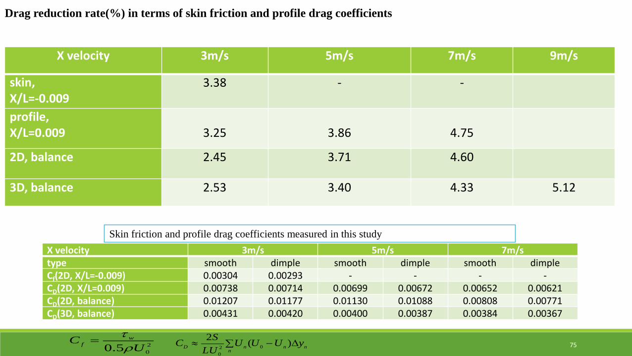
X velocity 3m/s 5m/s 7m/s 9m/s
skin,X/L=-0.009
3.38 - -
profile,X/L=0.009 3.25 3.86 4.75
2D, balance 2.45 3.71 4.60
3D, balance 2.53 3.40 4.33 5.12
Drag reduction rate(%) in terms of skin friction and profile drag coefficients
X velocity 3m/s 5m/s 7m/stype smooth dimple smooth dimple smooth dimpleCf(2D, X/L=-0.009) 0.00304 0.00293 - - - -CD(2D, X/L=0.009) 0.00738 0.00714 0.00699 0.00672 0.00652 0.00621CD(2D, balance) 0.01207 0.01177 0.01130 0.01088 0.00808 0.00771CD(3D, balance) 0.00431 0.00420 0.00400 0.00387 0.00384 0.00367
Skin friction and profile drag coefficients measured in this study
205.0 U
C wf ρ
τ= ∑ ∆−≈
nnnnD yUUU
LUSC )(2
020
75

Dimples reduced the surface energy and increased the hydrophobicity
76
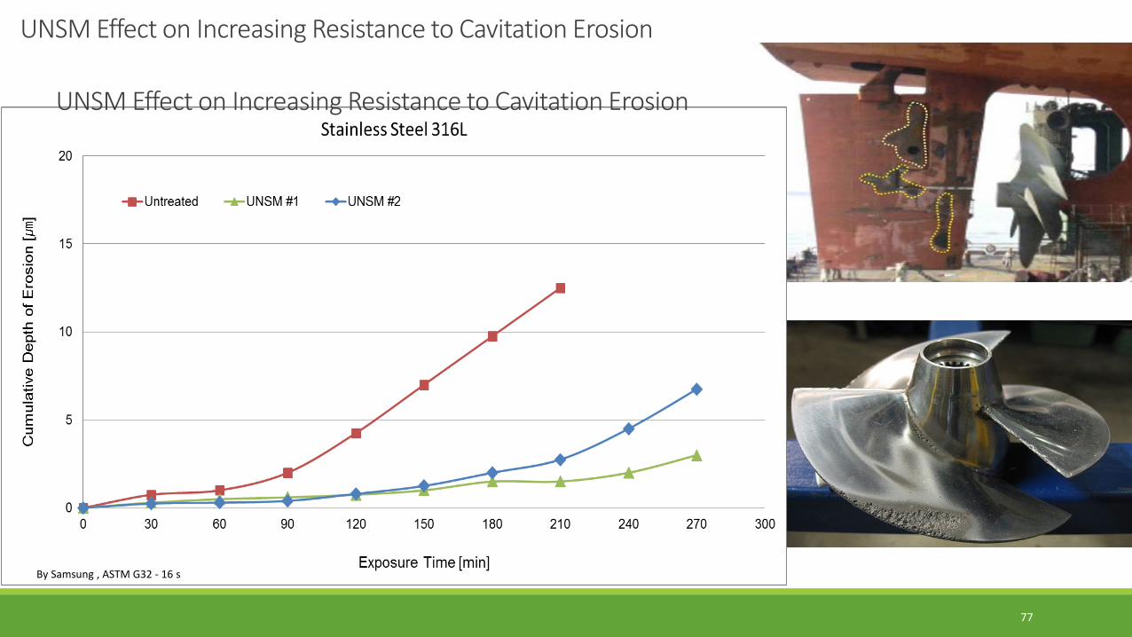
By Samsung , ASTM G32 - 16 s
UNSM Effect on Increasing Resistance to Cavitation Erosion
UNSM Effect on Increasing Resistance to Cavitation Erosion
77
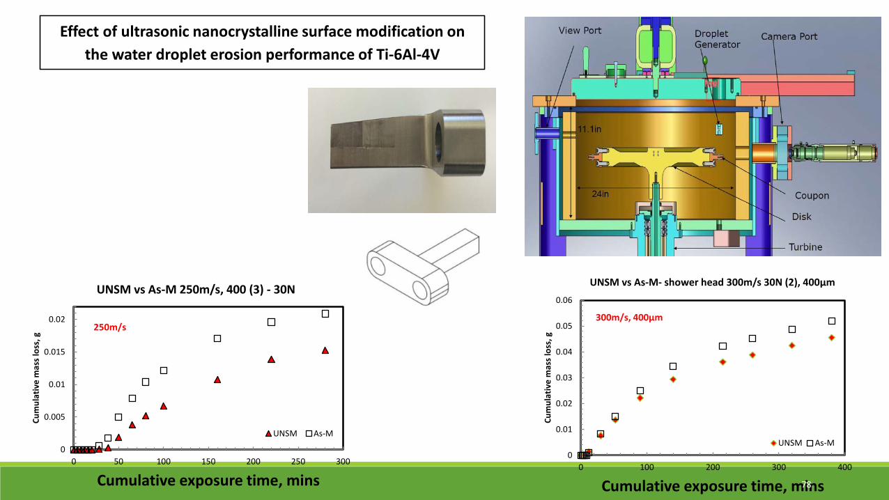
Effect of ultrasonic nanocrystalline surface modification on the water droplet erosion performance of Ti-6Al-4V
0
0.005
0.01
0.015
0.02
0 50 100 150 200 250 300
Cum
ulat
ive
mas
s lo
ss, g
Cumulative exposure time, mins
UNSM vs As-M 250m/s, 400 (3) - 30N
UNSM As-M
250m/s
0
0.01
0.02
0.03
0.04
0.05
0.06
0 100 200 300 400
Cum
ulat
ive
mas
s lo
ss, g
Cumulative exposure time, mins
UNSM vs As-M- shower head 300m/s 30N (2), 400µm
UNSM As-M
300m/s, 400µm
78