a new cascaded multilevel statcom using ... new cascaded multilevel statcom using fuzzy controller 3...
TRANSCRIPT
International Journal of Electrical Engineering. ISSN 0974-2158 Volume 9, Number 1 (2016), pp. 1-13 © International Research Publication House http://www.irphouse.com
A NEW CASCADED MULTILEVEL STATCOM USING FUZZY CONTROLLER FOR HIGH POWER APPLICATIONS
Mr. S. Mahaboob basha1
Assistant professor Dept. of EEE, A.I.T.S
Mr. CH. Lenin Babu2
Assistant professor Dept. of EEE, A.I.T.S
B. Saraswathi3
PG Scholar Dept. of EEE, A.I.T.S
Kadapa 516001, A.P., INDIA.
ABSTRACT In this paper, in order to obtain VAR compensation multi level inverter topology which is based on cascaded two level inverter is proposed. Through the open end windings of three phase transformer standard two level inverters are connected in cascade. In order to obtain four level operation the DC link voltages of the inverters are regulated. By using Fuzzy controller in this circuit THD can be reduced. So to predict the performance of the proposed circuit simulation study is carried out in MATLAB/SIMULINK environment and the results are verified in both balanced and unbalanced conditions. Keywords : DC-link voltage balance, multilevel inverter, power quality(PQ), static compensator(STATCOM). I. INTRODUCTION In recent years, the custom power technology, the low- voltage counterpart of the more widely known flexible ac transmission system (FACTS) technology, aimed at high-voltage power transmission applications, has emerged as a credible solution to solve many of the problems relating to continuity of supply at the end-user level. Both the FACTS and custom power concepts are directly credited to EPRI. At present, a wide range of very flexible controllers, which capitalize on newly available power electronics components, are emerging for custom power applications. Among these, STATCOM is popularly accepted as a reliable reactive power controller replacing conventional VAR compensators, such as the thyristor-switched capacitor (TSC) and thyristor controlled reactor (TCR). This device provides reactive power compensation, active power oscillation damping, flicker attenuation, voltage regulation, etc.[1] The VSC connected in shunt with the ac system provides a multifunctional topology which can be used for up to three quite distinct purposes
2 Mr. S. Mahaboob, Mr. CH. Lenin Babu and B. Saraswathi
1. Voltage regulation and compensation of reactive power 2. Correction of power factor 3. Elimination of current harmonics.
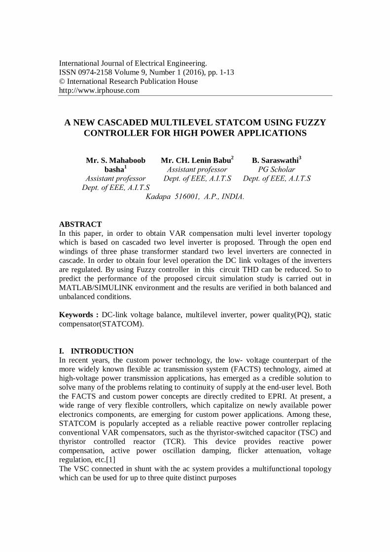
Generally, in high-power applications, VAR compensation is achieved using multilevel inverters [2]. These inverters consist of a large number of dc sources which are usually realized by capacitors. Hence, the converters draw a small amount of active power to maintain dc voltage of capacitors and to compensate the losses in the converter. However, due to mismatch in conduction and switching losses of the switching devices, the capacitors voltages are unbalanced. Balancing these voltages is a major research challenge in multilevel inverters. Due to this power quality issues also increased. Various control schemes using different topologies are reported in [3-7]. In order to over come these problems the proposed control scheme has been implemented. Static VAR compensation by cascading conventional multi-level/two level inverters is an attractive solution for high power applications. The topology consists of standard multilevel/two- level inverters connected in cascade through open-end windings of a three-phase transformer. Such topologies are popular in high-power drives [8]. One of the advantages of this topology is that by maintaining asymmetric voltages at the dc links of the inverters, the number of levels in the output voltage waveform can be increased. This improves PQ [8]. Therefore, overall control is simple compared to conventional multilevel inverters. Various VAR compensation schemes based on this topology are reported in[10]–[12]. The dc-link voltage balance between the inverters is affected by the reactive power supplied to the grid. In this paper, a static VAR compensation scheme is proposed for a cascaded two-level inverter-based multilevel inverter. The dc-link voltages of the inverters are regulated at asymmetrical levels to obtain four-level operation. To verify the efficacy of the proposed control strategy, the simulation study is carried out for balanced and unbalanced supply-voltage conditions.. The power system model considered in this paper[13] is shown in figure below
Fig. 1. Power system and the STATCOM model
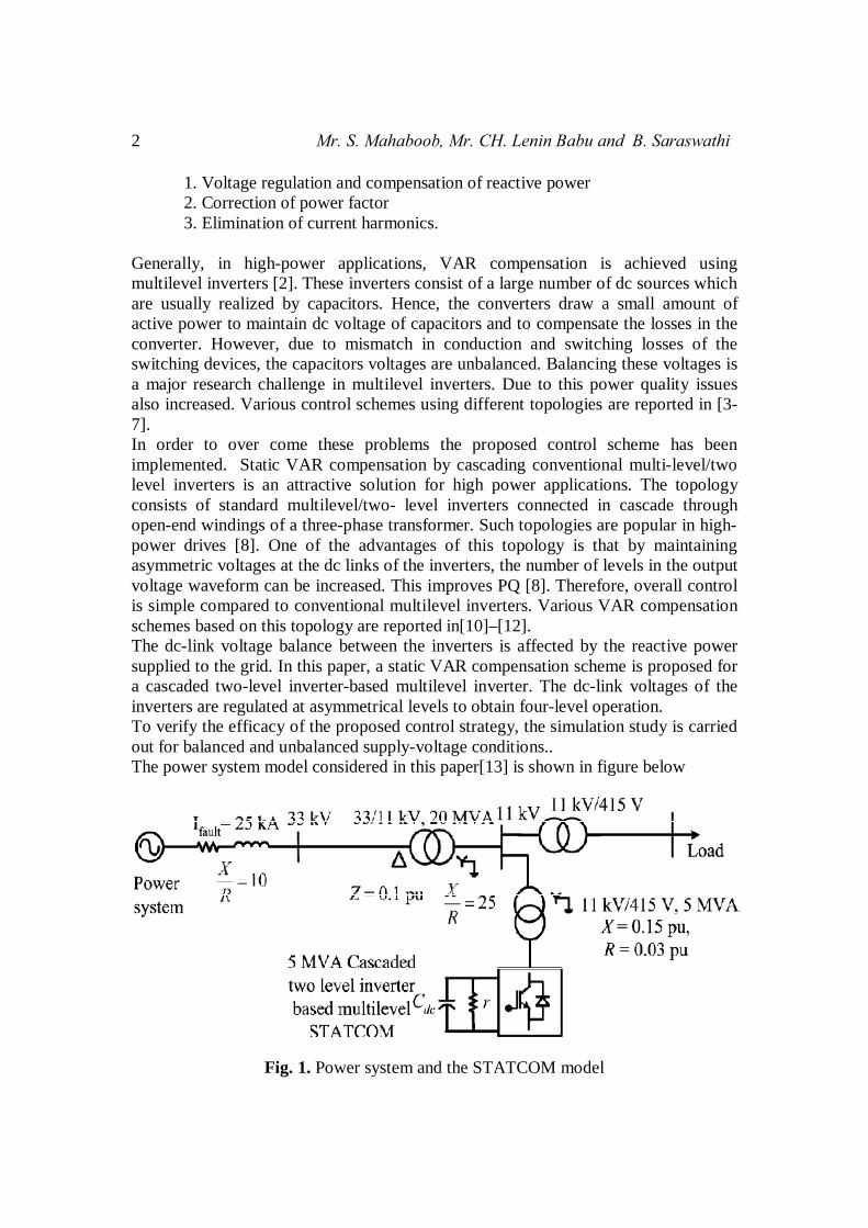
A New Cascaded Multilevel Statcom Using Fuzzy Controller 3 For High Power Applications II. CASCADED INVERTER-BASED MULTI LEVEL STATCOM Fig. 2 shows the circuit topology of the cascaded two-level inverter-based multilevel STATCOM using standard two-level inverters. The inverters are connected on the low-voltage (LV) side of the transformer and the high-voltage (HV) side is connected to the grid.
Fig. 2. Cascaded two-level inverter based multilevel STATCOM
In this figure , , , , , are the source voltages referred to LV side of the transformer,
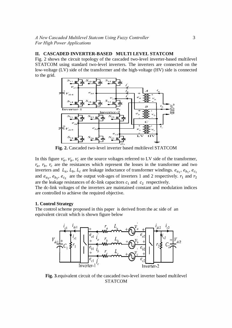
, , are the resistances which represent the losses in the transformer and two inverters and , , are leakage inductance of transformer windings. , , and , , are the output volt-ages of inverters 1 and 2 respectively. and are the leakage resistances of dc-link capacitors and respectively. The dc-link voltages of the inverters are maintained constant and modulation indices are controlled to achieve the required objective. 1. Control Strategy The control scheme proposed in this paper is derived from the ac side of an equivalent circuit which is shown figure below
Fig. 3.equivalent circuit of the cascaded two-level inverter based multilevel STATCOM
4 Mr. S. Mahaboob, Mr. CH. Lenin Babu and B. Saraswathi
Assuming = = =r and L and applying KVL on the ac side, the dynamic model can be derived as[14]
′
′
′
=
0 00 00 0′
′
′ +
′
′
′ (1)
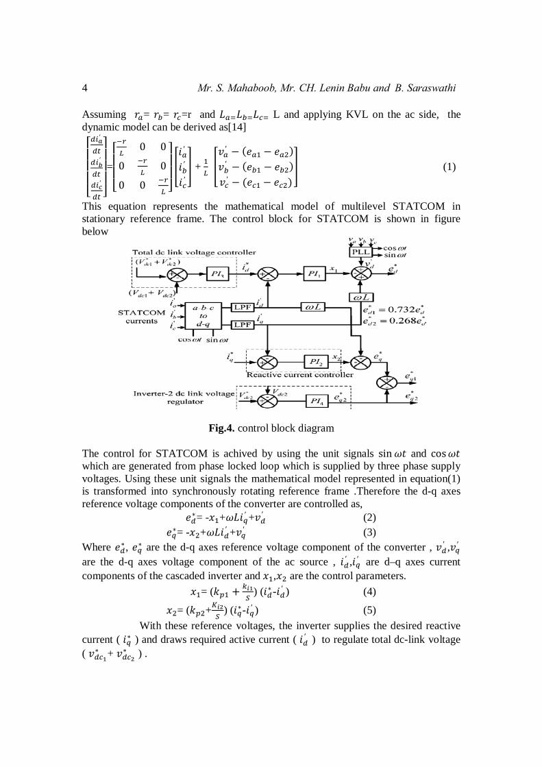
This equation represents the mathematical model of multilevel STATCOM in stationary reference frame. The control block for STATCOM is shown in figure below
Fig.4. control block diagram The control for STATCOM is achived by using the unit signals sin and cos which are generated from phase locked loop which is supplied by three phase supply voltages. Using these unit signals the mathematical model represented in equation(1) is transformed into synchronously rotating reference frame .Therefore the d-q axes reference voltage components of the converter are controlled as, = - + ′ + ′ (2)
= - + ′ + ′ (3) Where , are the d-q axes reference voltage component of the converter , ′ , ′ are the d-q axes voltage component of the ac source , ′ , ′ are d–q axes current components of the cascaded inverter and , are the control parameters. = ( ) ( - ′ ) (4)
= ( + ) ( - ′ ) (5) With these reference voltages, the inverter supplies the desired reactive current ( ) and draws required active current ( ′ ) to regulate total dc-link voltage ( + ) .
A New Cascaded Multilevel Statcom Using Fuzzy Controller 5 For High Power Applications 2. DC-Link Balance Controller The active power transfer between the source and inverter depends on and is usually small in the inverters supplying VAR to the grid [1]. Therefore, the Q -axis reference voltage component of inverter-2is derived to control the dc-link voltage of inverter-2 as, The p-q axes reference voltage component of inverter-1 is obtained as = √ It results in four-level operation in the output voltage and improves the harmonic spectrum. The reference voltages generated for inverter-2 are in phase opposition to that of inverter-1. From the reference voltages, gate signals are generated using the sinusoidal pulse-width modulation (PWM) technique [15]. Since the two inverters’ reference voltages are in phase opposition, the predominant harmonic appears at double the switching frequency. 3. Unbalanced Conditions Network voltages are unbalanced due to asymmetric faults or unbalanced loads. As a result, negative-sequence voltage appears in the supply voltage. This causes a double supply frequency component in the dc-link voltage of the inverter. This double frequency component injects the third harmonic component in the ac side [17]. Moreover, due to negative-sequence voltage, large negative-sequence current flows through the inverter which may cause the STATCOM to trip [16][18]. Therefore, during unbalance, the inverter voltages are controlled in such a way that either negative-sequence current flowing into the inverter is eliminated or reduces the unbalance in the grid voltage. In the latter case, STATCOM needs to supply large currents since the interfacing impedance is small. This may lead to trip- ping of the converter. The negative-sequence reference voltage components of the inverter and are controlled similar to positive-sequence components in the negative synchronous rotating frame as [18]
= - + (- ) ′ + ′ (13) = - + (- ) ′ + ′ (14)
Where ′ , ′ are d-q axes negative-sequence voltage components of the supply and ′ , ′ are d-q axes negative-sequence current components of the inverter,
respectively. The control parameters and are controlled as follows: = ( + ) ( - ′ ) (15)
= ( + ) ( - ′ ) (16) The reference values for negative-sequence current components and are set at zero to block negative-sequence current from flowing through the inverter. III. STABILITY ANALYSIS Considering the dc side of the two inverters in Fig. 3, the transfer function is as follows:
6 Mr. S. Mahaboob, Mr. CH. Lenin Babu and B. Saraswathi
∆∆ = (17) And the transfer function of inverter2 is ∆∆ = (18) From the transfer functions (17) and (18), it can be represent that the denominator is a function of resistances, reactance and modulation indices. Although the, denominator includes an operating condition term( - ), the product of operating term is always positive. Hence, the poles of transfer function always lie on the left half of the S-plane. However, numerators of the transfer functions are functions operating conditions of ′ , ′ , and . The positions of zeros primarily depends on ′ , 1 and 2 . The sign of these variables changes according to the mode of operation. Therefore, zeros of the transfer functions shift to the right half of the S-plane for certain operating conditions. This system is said to be non minimum phase and there is a limit on achievable dynamic response [19]. The system may exhibit oscillatory instability when there is a step change in reference for high controller gains. Therefore, the controller gains should be designed suitably to avoid the instability. This behavior is similar to that of the two-level inverter-based STATCOM [20], [21]. IV. SIMULATION RESULTS
Table:1 Simulation parameter
Rated power 5MVA Transformer voltage rating 11kv400/ AC supply frequency, f 50 Hz Inverter1 dc link voltage 659V Inverter2 dc link voltage 241V Transformer leakage reactance 15%
Transformer resistance 3% DC link capacitances 50mF Switching frequency 1200 Hz
The proposed STATCOM based two level inverter system is studied using MATLAB/ SIMULINK. The overall system configuration and controller are shown in fig 5(a), (b) & (c) for balanced, unbalanced condition and controller circuits. The simulation study is carried out using them. The system parameters are given in Table I. In fault condition, a single-phase-to ground fault is created at time=1.2s to 1.5s, on the phase of the HV side of the 33/11-kV transformer. The fault is cleared after 200ms. Fig. 6(a) (b) (c) and (d) are shows Balanced Single line to ground fault (voltage & current), d-q the-axes components of negative-sequence current and Voltage of the converter. These currents are regulated at zero during the fault condition. Fig. 7(a) (b) and (c) are
A New Cascaded Multilevel Statcom Using Fuzzy Controller 7 For High Power Applications shows unbalanced Single line to ground fault (voltage & current), the d-q axes components of negative-sequence current and Voltage of the converter.
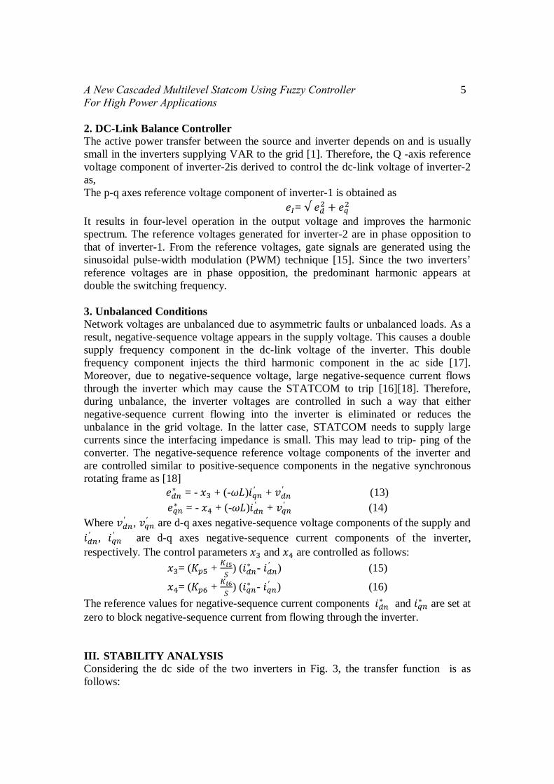
Fig. 5(a). circuit diagram for reactive power control
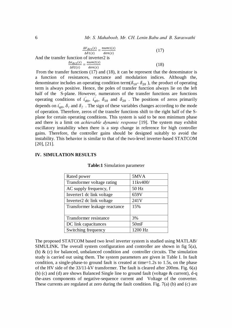
Fig. 5(b). circuit diagram for fault condition.
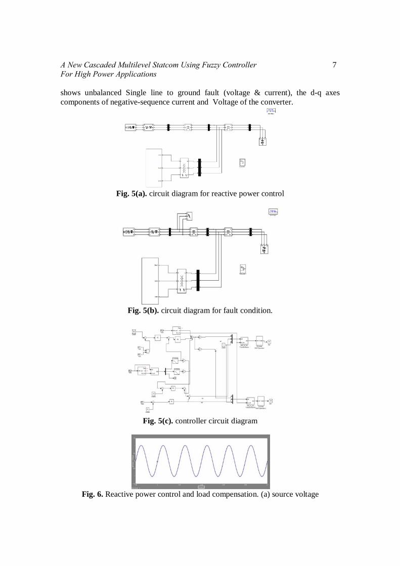
Fig. 5(c). controller circuit diagram
Fig. 6. Reactive power control and load compensation. (a) source voltage
8 Mr. S. Mahaboob, Mr. CH. Lenin Babu and B. Saraswathi
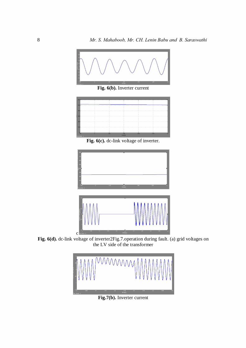
Fig. 6(b). Inverter current
Fig. 6(c). dc-link voltage of inverter.
c Fig. 6(d). dc-link voltage of inverter2Fig.7.operation during fault. (a) grid voltages on
the LV side of the transformer
Fig.7(b). Inverter current
A New Cascaded Multilevel Statcom Using Fuzzy Controller 9 For High Power Applications
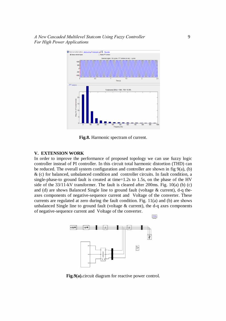
Fig.8. Harmonic spectram of current.
V. EXTENSION WORK In order to improve the performance of proposed topology we can use fuzzy logic controller instead of PI controller. In this circuit total harmonic distortion (THD) can be reduced. The overall system configuration and controller are shown in fig 9(a), (b) & (c) for balanced, unbalanced condition and controller circuits. In fault condition, a single-phase-to ground fault is created at time=1.2s to 1.5s, on the phase of the HV side of the 33/11-kV transformer. The fault is cleared after 200ms. Fig. 10(a) (b) (c) and (d) are shows Balanced Single line to ground fault (voltage & current), d-q the-axes components of negative-sequence current and Voltage of the converter. These currents are regulated at zero during the fault condition. Fig. 11(a) and (b) are shows unbalanced Single line to ground fault (voltage & current), the d-q axes components of negative-sequence current and Voltage of the converter.
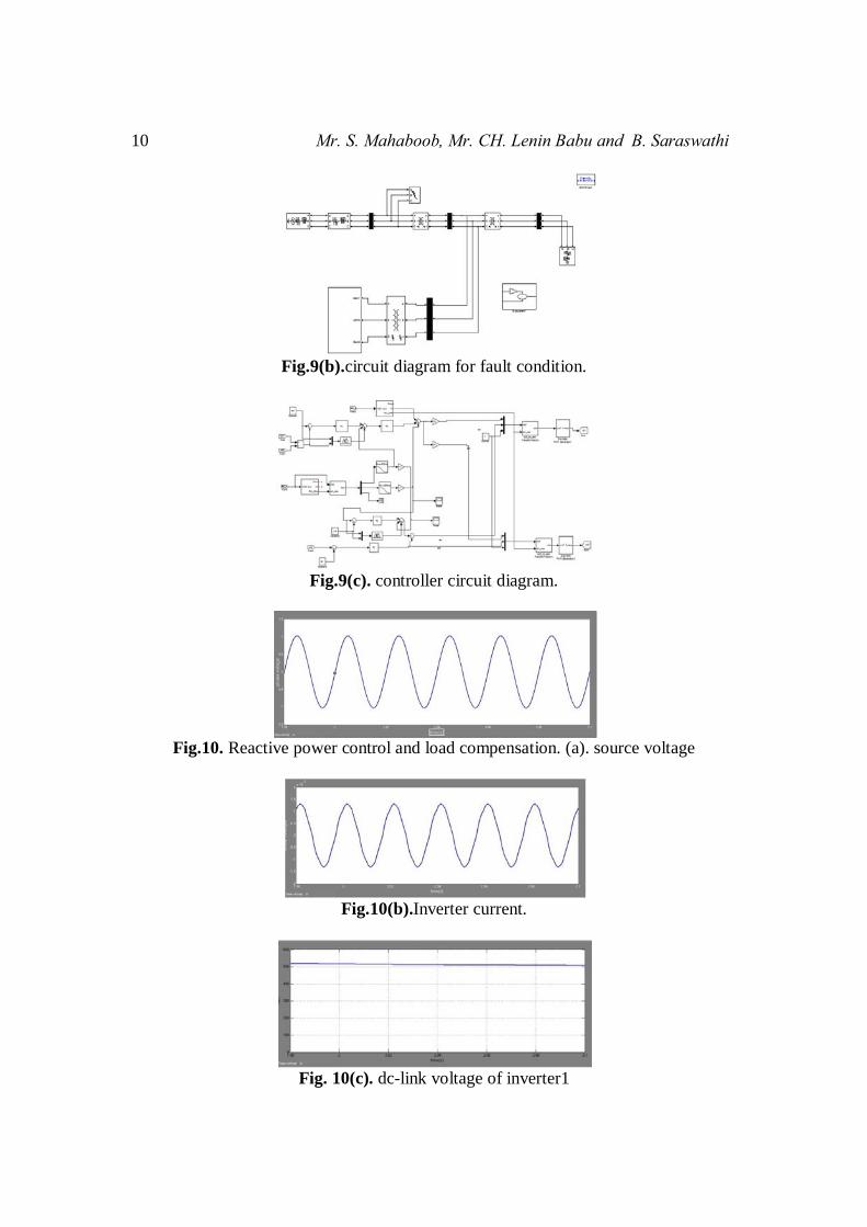
Fig.9(a).circuit diagram for reactive power control.
10 Mr. S. Mahaboob, Mr. CH. Lenin Babu and B. Saraswathi
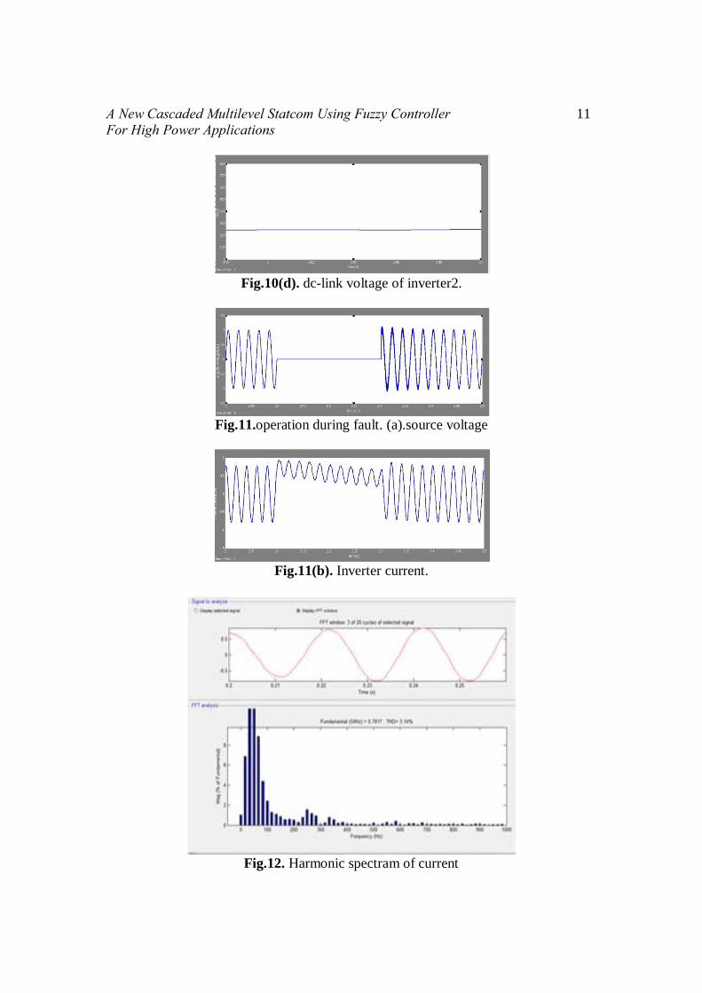
Fig.9(b).circuit diagram for fault condition.
Fig.9(c). controller circuit diagram.
Fig.10. Reactive power control and load compensation. (a). source voltage
Fig.10(b).Inverter current.
Fig. 10(c). dc-link voltage of inverter1
A New Cascaded Multilevel Statcom Using Fuzzy Controller 11 For High Power Applications
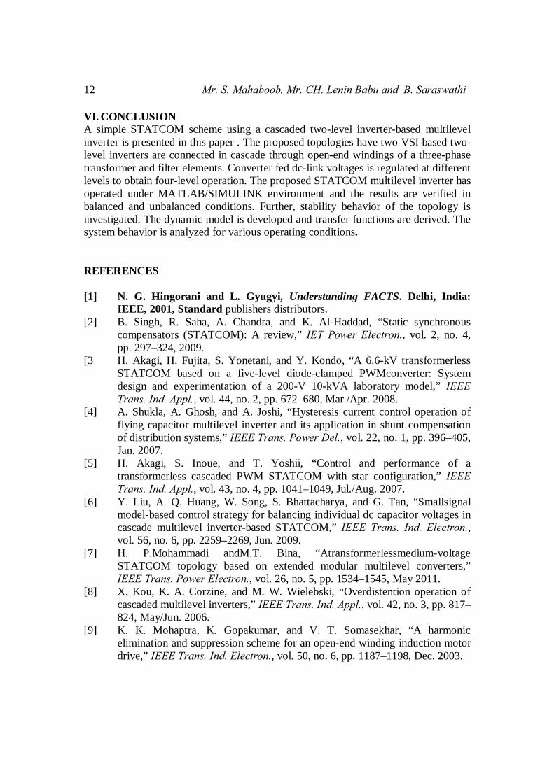
Fig.10(d). dc-link voltage of inverter2.
Fig.11.operation during fault. (a).source voltage
Fig.11(b). Inverter current.
Fig.12. Harmonic spectram of current
12 Mr. S. Mahaboob, Mr. CH. Lenin Babu and B. Saraswathi
VI. CONCLUSION A simple STATCOM scheme using a cascaded two-level inverter-based multilevel inverter is presented in this paper . The proposed topologies have two VSI based two-level inverters are connected in cascade through open-end windings of a three-phase transformer and filter elements. Converter fed dc-link voltages is regulated at different levels to obtain four-level operation. The proposed STATCOM multilevel inverter has operated under MATLAB/SIMULINK environment and the results are verified in balanced and unbalanced conditions. Further, stability behavior of the topology is investigated. The dynamic model is developed and transfer functions are derived. The system behavior is analyzed for various operating conditions. REFERENCES [1] N. G. Hingorani and L. Gyugyi, Understanding FACTS. Delhi, India:
IEEE, 2001, Standard publishers distributors. [2] B. Singh, R. Saha, A. Chandra, and K. Al-Haddad, “Static synchronous
compensators (STATCOM): A review,” IET Power Electron., vol. 2, no. 4, pp. 297–324, 2009.
[3 H. Akagi, H. Fujita, S. Yonetani, and Y. Kondo, “A 6.6-kV transformerless STATCOM based on a five-level diode-clamped PWMconverter: System design and experimentation of a 200-V 10-kVA laboratory model,” IEEE Trans. Ind. Appl., vol. 44, no. 2, pp. 672–680, Mar./Apr. 2008.
[4] A. Shukla, A. Ghosh, and A. Joshi, “Hysteresis current control operation of flying capacitor multilevel inverter and its application in shunt compensation of distribution systems,” IEEE Trans. Power Del., vol. 22, no. 1, pp. 396–405, Jan. 2007.
[5] H. Akagi, S. Inoue, and T. Yoshii, “Control and performance of a transformerless cascaded PWM STATCOM with star configuration,” IEEE Trans. Ind. Appl., vol. 43, no. 4, pp. 1041–1049, Jul./Aug. 2007.
[6] Y. Liu, A. Q. Huang, W. Song, S. Bhattacharya, and G. Tan, “Smallsignal model-based control strategy for balancing individual dc capacitor voltages in cascade multilevel inverter-based STATCOM,” IEEE Trans. Ind. Electron., vol. 56, no. 6, pp. 2259–2269, Jun. 2009.
[7] H. P.Mohammadi andM.T. Bina, “Atransformerlessmedium-voltage STATCOM topology based on extended modular multilevel converters,” IEEE Trans. Power Electron., vol. 26, no. 5, pp. 1534–1545, May 2011.
[8] X. Kou, K. A. Corzine, and M. W. Wielebski, “Overdistention operation of cascaded multilevel inverters,” IEEE Trans. Ind. Appl., vol. 42, no. 3, pp. 817–824, May/Jun. 2006.
[9] K. K. Mohaptra, K. Gopakumar, and V. T. Somasekhar, “A harmonic elimination and suppression scheme for an open-end winding induction motor drive,” IEEE Trans. Ind. Electron., vol. 50, no. 6, pp. 1187–1198, Dec. 2003.

A New Cascaded Multilevel Statcom Using Fuzzy Controller 13 For High Power Applications [10] Y. Kawabata, N. Yahata,M. Horii, E. Egiogu, and T. Kawabata, “SVG using
open winding transformer and two inverters,” in Proc., 35th Annual IEEE Power Electron. Specialists Conf., 2004, pp. 3039–3044.
[11] S. Ponnaluri, J. K. Steinke, P. Steimer, S. Reichert, and B. Buchmann, “Design comparison and control of medum voltage STATCOM with novel twin converter topology,” in Proc., 35th Annu. IEEE Power Electron. Specialists Conf., 2004, pp. 2546–2550.