a multi-view camera-projector system for object detection ...ngans/papers/icra 2013...
TRANSCRIPT

A Multi-View Camera-Projector System for Object Detection and
Robot-Human Feedback
Jinglin Shen, Jingfu Jin and Nicholas Gans
Abstract— In this paper, we present a novel camera-projectorsystem for assisting robot-human interaction. The system iscomprised of a stereo camera pair and a DLP projector. Theproposed system provides feedback information indicating therobot’s perception of the environment and what action a humanuser desires. Feedback is delivered by iteratively spotlightingobjects in the environment using the projector. When thespotlight lands on an object that the human user wants therobot to retrieve, he or she can confirm the object selection, andthe robot will perform a grasping task to retrieve the selectedobject. In this investigation, the proposed camera-projectorperforms three tasks: 1) Actively detect visually salient objectsin the scene from the two camera views using a visual attentionmodel. 2) Locate the detected objects using a trifocal tensorbased object matching method, and project a spot of light onthe objects to provide information back to the human user. 3)Reconstruct the 3D position of the target to plan robot motionand conduct vision-based control to move a robot manipulatorto grasp the object. Experimental results of human-directedobject grasping task are presented to demonstrate the functionsof the proposed system.
I. INTRODUCTION
In the near future, robots will be increasingly used for
human service and assistance applications in the home.
Examples of recent applications include service robots that
can assist people eating and shaving [1], a mobile robotic
follower to carry oxygen tanks [2], and unloading items
from a dishwasher [3]. Many of these applications involve
object approaching, grasping and manipulation, which often
requires either a controlled environment with known 3D
structures or an efficient way to acquire information about
the target object in order to plan robot motion.
To extend the abilities of service robots, human-robot
interaction and human-in-the-loop systems draw increasing
research attention. Such systems allow human operators to
convey their commands or intentions to robots using natural
interfaces like gesture [4] and voice [5]. In other cases,
human input is used to help robot better understand the
environment, for example in [6], the operator uses voice
commands to enhance segmentation of occluding objects in
the image views.
While natural interfaces for human-robot interaction re-
ceives extensive study, it appears that less attention has been
paid to how robots convey their views of the environment or
tasks to the human operator in a natural way. One approach
would be to display information that the robots obtain about
This work was supported by Texas Instruments OMAP University Re-search Program
J. Shen, J. Jin and N. Gans are with the Department of ElectricalEngineering, University of Texas at Dallas, Richardson, TX 75080, USA{shen.jinglin, jxj115020, ngans}@utdallas.edu
Fig. 1. Structure of the camera-projector system
object locations, shapes, sizes etc. directly on or near the
objects rather than on a computer monitor. The major goal
of this work is to develop a camera-projector system that
enables robots to provide such instructional feedback. Our
motivating example is an object grasping task. The system
projects a spotlight on different objects that are detected,
which it believes a human user might want it to retrieve.
When the spotlight arrives on a desired object, the human
user can confirm selection and the robot grasps the object.
We present a camera-projector system and demonstrate a
human-robot interaction experiment based on it. To locate
objects that would likely interest a human user, we modify
Itti’s visual attention model [7] by adding depth information
as a channel to the saliency map and adapt a weighting
scheme based on information theory that was proposed in
[8]. Then, the detected objects are mapped from camera
views to the projector view to provide feedback information.
This requires first matching the objects in the camera views.
A novel object matching method based on the trifocal
constraints is proposed. Lighting from the projector is used,
but in a way that differs from traditional structured light
methods. In the literature, various algorithms have been
developed for stereo matching and 3D reconstruction based
on stereo depth maps [9], [10]. Structured light methods
generally work better for objects that lack visual texture
or features [11]. In recent years, the Kinect device, which
uses infrared structured light to achieve depth measurement,
has gained a lot of research interests in the area of human-
computer interaction [12], [13]. Recently, Li, et al., proposed
to combine the stereo matching and structured light methods
to compensate for their drawbacks [14]. However, most
existing stereo matching methods are either not accurate or
too slow to use in real time.
The system works as follow. Object detection is first done
in an bottom-up manner by using the visual attention model.
Objects are then segmented in the saliency maps of the
two camera views separately. Segmented objects in the two
camera views are matched by projecting a spotlight, whose
position is calculated from trifocal constraints for each pair of
matching candidates. Correct matching will cause the object
to be illuminated by the spotlight, which can be detected
by the cameras. Shape and area comparison is done ahead
of the matching process to reduce the number of possible
matches for each object. By including depth information in
the saliency map, objects that appears occluded in the camera
views but at different depth can be separated. After match-
ing each segmented object in camera views, the projector
projects a spotlight on all matched objects one by one and
waits for human input. Once a human command is received,
further grasping operation can be performed. The structure
of the system is illustrated in Fig. 1.
A closely related work is done by Rasolzadeh et al. [15].
They developed a vision attention based active vision system
with four cameras to guild robot grasping tasks. However, the
object segmentation and 3D reconstruction is based on dense
stereo matching. Another major difference is that our system
is capable of providing feedback information through natural
interface by directly projecting on the objects.
The paper is organized as follows. Related background
is given in Section II. The system calibration procedure
is introduced in Section III. Section IV describes how the
systems functions are realized, including objection detection
based on the visual attention model and trifocal constraints,
illuminating the detected objects and stereo reconstruction
for visual servoing. Then we demonstrate the experimental
result in Section V, and finally Section VI gives the conclu-
sion and future works.
II. BACKGROUND
A. Camera and Projector Model
The coordinates of a 3D point are defined as M =[X ,Y,Z,1]T using homogeneous coordinates measured in
the inertial world reference frame. Its corresponding 2D
projection is defined as m= [x,y,1]T as measured in the cam-
era frame. Under the pinhole camera model, the projection
relation between M and m is given by
m = PM =
1Zc
0 0 0
0 1Zc
0 0
0 0 1Zc
0
[
R t
0 1
]
M, (1)
where R ∈ SO(3) and t ∈ R3 are rotation and translation of
the camera frame with respect to the world origin. P ∈R3×4
is defined as the projection or camera matrix, and Zc is the Z
coordinate of the point as measured in the camera frame. The
homogeneous coordinates m is converted into coordinates in
image plane by
p = Km,
where K ∈ R3×3 is the calibration matrix of the camera.
A projector can be modeled as a dual of a pinhole camera,
with the difference being the direction of projection. That is,
for a camera, a point on a 3D surface in space projects to a
2D image point. While for a projector, a 2D image point m
is projected as a line L in 3D space (i.e. L is the preimage
of m). The intersection of the line L with a surface results
in a point of light on the surface. To distinguish between the
directions of projection, we define projecting from 3D space
to 2D image plane to be “projecting in” (i. e. projection of
camera), and projecting from 2D image to 3D space to be
“projecting out” (i. e. projection of projector).
B. Trifocal Tensor
The trifocal tensor encodes the geometric relation among
three camera views and is analogous to the role of the
fundamental matrix in two-view geometry. Since the pinhole
model of a projector is reciprocal to a camera, the geometry
of the trifocal tensor relation is still valid if any of three
cameras is replaced by a projector. Therefore, we will talk
about general three-view systems in the following discussion.
The trifocal tensor T can be presented using a set of
three matrices as T = {T1,T2,T3}, where Ti ∈ R3×3 for
i ∈ {1,2,3}. According to [16], given three fixed projection
matrices P = [I|0], P′ = [A|a] and P′′ = [B|b] (without loss
of generality, the world frame is assumed to align with one
camera frame, as defined by projection matrix P), the trifocal
tensor is uniquely defined by
Ti = aibT4 −a4bT
i , (2)
where ai and bi are the ith column of P′ and P′′, i ∈ {1,2,3}.
Conversely, if the trifocal tensor is known, projection matri-
ces P′ and P′′ can be recovered as
P′ = [T1e′′,T2e′′,T3e′′,e′] (3)
P′′ = [(e′′e′′T )T T1 e′,(e′′e′′T )T T
2 e′,(e′′e′′T )T T3 e′,e′′], (4)
where e′ and e′′ are the epipoles in the views defined by P′
and P′′. The epipoles e′ and e′′ can also be solved from the
trifocal tensor as the left null-vectors of matrices [u1,u2,u3]and [v1,v2,v3] where ui and vi are the left and right null-
vectors of Ti respectively. Note that (2) to (4) correspond to
the case when P = [I|0] (i.e. the world origin is fixed at the
center of P). Detailed analysis and the trifocal tensor in the
general case is given in [16].
Like the epipolar constraint in epipolar geometry, there
are constraints among corresponding points and lines in the
three views for the trifocal tensor, namely incidence relations.
There are several incidence relations, including line-line-line
correspondence and point-line-line correspondence, etc.. In
this work, the point-point-point correspondence relation is
used for solving the trifocal tensor, and the point-line-point
correspondence is used to locate matches of the selected
points. The point-point-point correspondence is illustrated in
Fig. 2(a), and the relation defines a constraint expressed using
Matrix notation as
[m′]×(∑i
miTi)[m′′] = 03×3, i ∈ {1,2,3} (5)
where [m]× refers to the 3 × 3 skew-symmetric matrix
made from vector m.
The point-line-point correspondence is illustrated in Fig.
2(b). The preimage π ′ of line l′ in view 2 defines a plane,
which induces a homography between the image points m

(a) (b)
Fig. 2. (a) The point-point-point correspondence; (b) The point-line-pointcorrespondence.
and m′′ in the other two views. Therefore, given a point m
in view 1 and a line l′ in view 2 which passes through m′,
the image point m′′ can be found in view three by
m′′ = H13(l′)m = (∑
i
miTi)l′, i ∈ {1,2,3} (6)
where H13 is the homography matrix induced by l′, and mi
is the ith term of m. Note that l′ can be any line that passes
through m′ except the epipolar line, which corresponds to a
degenerate case of the trifocal tensor.
III. SYSTEM CALIBRATION USING THE TRIFOCAL
TENSOR
In this section, the calibration procedure of the camera-
projector system is discussed. Given fixed relative positions
among the three views, the calibration procedure results
in projection matrices P, P′ and P′′. Calibration of such
a camera-projector system involves intrinsic calibration of
both cameras and the projector, and extrinsic calibration
among the three views using the trifocal tensor. Intrinsic
calibrations are performed first. Camera intrinsic calibration
is done using the Matlab Camera Calibration Toolbox [17].
Projector intrinsic calibration is done using the method of
Falcao et al. [18], which is also based on [17].
After intrinsic calibration of the cameras and projector, we
apply the Gold Standard algorithm [16] to calculate the tri-
focal tensor and recover the projection matrices. Image cor-
respondences are acquired by using the projector to display a
checkerboard pattern of known size on several different pla-
nar surfaces. The inner corners of the checkerboard squares
are extracted from the camera views to get n >= 7 sets of
feature points. Using the captured images correspondences,
an initial linear solution can be calculated according to the
point-point-point relation in (5). A nonlinear optimization
step then follows using the Levenberg-Marquardt method,
taking the linear solution as a starting point.
IV. CAMERA-PROJECTOR SYSTEM FUNCTIONS
The major functions of the system include finding and
matching objects using a saliency map and trifocal con-
straints, providing feedback information to the human op-
erator and recovering 3D structure of the scene.
A. Object Detection based on the Visual Attention Model
In the saliency-based visual attention model, attractiveness
of visual stimuli is represented as a saliency map, which
models visual response to a given scene. Several methods
have been proposed for object detection based on visual
(a) (b) (c)
(d) (e) (f)
Fig. 3. Modified saliency model with the disparity map. (a) The scene ob-served from left camera view; (b) Disparity map generated using structuredlight from the projector; (c) Disparity map after background removal; (d)Saliency map generated using Itti’s model; (e) Saliency map generated bydirectly adding the disparity map as a channel; (f) Saliency map generatedusing the disparity map after background removal.
attention [7], [19]. Regions of an image with high saliency
will likely be of interest to a human viewing the scene.
In addition to the common saliency channels such as color,
intensity and orientation, depth information is considered
an important factor that effects human visual attention in
some applications. The idea of adding depth information as
a channel first appeared in [20]. Depth information and stereo
disparity is used in various ways in [21], [22].
In this work, we add a disparity map as a feature map
to Itti’s saliency model and weight the feature maps using
an information theory based scheme. In recent years, the Mi-
crosoft Kinect has been a popular device for generating depth
maps using structured light. While it is an feasible option,
the projector in the system is used to project structured light
patterns so that no extra device is needed. Using the Kinect
to replace the stereo camera in the system is one direction
of our future work.
Generating a disparity map is a well studied problem
in computer vision. In this work, we adapt a structured
light method using temporally encoded binary stripe patterns
[23]. Directly adding the disparity map as a channel to
the saliency map will promote some background regions
after normalization, since there are regions in which depth
information cannot be recovered or have false matches, as
shown in Fig. 3(b). Therefore some pre-processing is done
on the disparity map to remove the background. In an indoor
environment with a background wall like the scene in Fig.
3 (a), the disparity of the background wall corresponds to
the maximum value in the histogram of the disparity map
in Fig. 3 (b). Removing the background from the disparity
map results in Fig. 3 (c). In more general cases with no
clear background, the disparity constraints determined by the
maximum range of the projector and the robot arm can be
used to define a threshold, and any disparity value under this
threshold should be suppressed.
When combining the feature maps into the final saliency
map, the feature maps with fewer regions standing out from
the background should be favored. We adapt the weighting

scheme proposed in [8]. The probability that an event is
observed from a feature map M is defined as
p(M) =∑i, j Mτ(i, j)
∑i, j M(i, j),
where Mτ(i, j) is the pixel value higher than a conspicuous
threshold τ , and M(i, j) is a pixel in the map M. The weight
of the feature map is decided by the amount of information
obtained from the map
I(M) =−log(p(M)).
The final saliency map is given by the combination of the
four feature maps in this manner:
S =4
∑i=1
I(Mi)Mi.
The saliency maps generated by this weighting scheme
are shown in Fig. 3(d)-(f) when using no disparity map, the
disparity map directly, and the disparity map after back-
ground removal respectively. It is can be seen from Fig.
3(d) that without the disparity map included, it is difficult
to separate any object on the table from the background.
By adding depth information in Fig. 3(e), the green tea box
can be distinguished from the jar in the back which appears
occluded by the tea box in the camera view. However, the
white/red cup on the left remains undistinguished from the
pile of books behind it, and the objects on the wall become
less salient. Saliency map with a disparity map after the
background removal in Fig. 3(f) shows that all the objects
can be easily segmented from the background.
B. Trifocal Tensor Based Object Matching
In order to project feedback information on detected
objects, they need to be located in the projector view. This
requires that the objects be matched in the two camera
views. We propose an object matching method based on
the trifocal tensor constraints that makes use of lighting
from the projector. Regions with high saliency values are
first segmented from the saliency maps. The centroids of
the contours that represent the salient areas are extracted as
candidates for matching.
The matching procedure works as follows. Let the sets
of all centroids in the two camera views be C and C′
respectively, and define subsets C̄ = {c|,c ∈ C,c 6= e} and
C̄′ = {c′|,c′ ∈C′,c′ 6= e′}, where e and e′ are the epipoles. If
c=e or c′=e′, the corresponding point in the projector view
can not be found. This is because the preimage of e and e′
are collinear, so the intersection is undefined, and the 3D
point can not be located. For any point c ∈ C̄ and c′ ∈ C̄′,
a point c′′ can be found in the projector view according to
the point-line-point incidence in (6) by constructing a line
l′ that passes c′ but not e′. Let M be a point in space; its
images points m, m′ and m′′ in the three views are uniquely
defined by the trifocal constraints. If c = m, the point c′′
found by the point-line-point correspondence coincides with
m′′ only when c′ = m′. Projecting a pattern out at c′′, the
preimage passes M, which will cause the pattern to be
detected at location c and c′ in the camera views. Otherwise,
if c′ = m̄′′ 6= m′, the point-line-point correspondence maps c′′
Fig. 4. Object matching based on the trifocal tensor. The correspondencem, l′ and m′′ satisfies the trifocal constraints defined by the camera-projectorconfiguration, while the correspondence m, l̄′ and m̄′′ does not.
to a different point m̄′′, whose preimage does not pass M. In
this work, we iterate through each pair of c ∈C and c′ ∈C′,
project out a white dot, and check the intensity change at
point c in the left camera view. When intensity change is
observed, a match between c and c′ is found for an object.
This is illustrated in Fig.4.
Some pre-processing can be done to reduce the number
of possible matches for an object before the matching
procedure. In this work, shape and area of the segmented
regions are used, assuming that the two cameras are located
close to each other and their facing angles are similar. For
each point c∈C, a subset S′ ⊆C′ can be defined as all c′ ∈C′
that satisfies the following criterion:∣
∣area(r)−area(r′)∣
∣< Ta
S(r,r′)< Ts,
where Ta and Ts are tunable thresholds, r and r′ are the
segmented regions whose centroids are c and c′, and S is the
similarity score defined by
S(r,r′) =7
∑i=1
∣
∣
∣
∣
∣
1∣
∣log(hri )∣
∣
−1
∣
∣log(hr′
i )∣
∣
∣
∣
∣
∣
∣
,
where hri and hr′
i are the ith Hu moments of r and r′. The
criterion means only regions with similar areas and shapes
are considered for matching. Then c is matched with c′ ∈ S′,
which usually reduces the number of possible matches to
1 or 2 in our experiments. A complete example of object
matching is shown in Fig. 5.
C. Presenting Feedback Information Using the Projector
Once the camera-projector system detects one or more
salient objects in the environment, it can provide information
back to the human by projecting certain patterns of light on
the objects. The feedback information can be used to indicate
the system’s knowledge of the positions, shapes, sizes of
the detected objects and so on, or to convey its planed task
for human confirmation when a object is selected through
natural interfaces. The process of projecting patterns on to
detected objects is similar to the trifocal tensor based method
for object matching described in Section IV-B.
For each object matched in the two camera views, the
bounding ellipses are found, and the corresponding points of
(a) (b) (c) (d) (e)
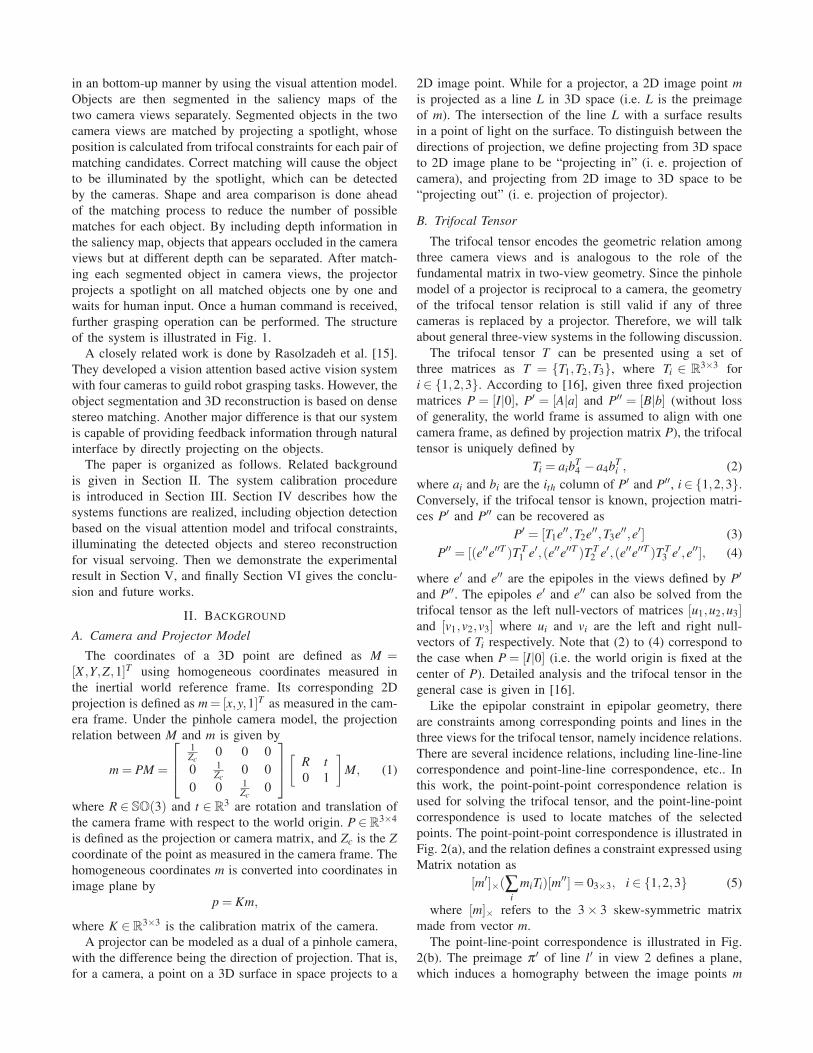
Fig. 5. Object matching in the left camera view(first row) and the right camera view(second row). (a) Original images; (b) Saliency maps; (c) saliencymaps after segmentation; (d) One object in the left view and its possible matches after shape and area comparison in the right view; (e) Matching resultusing the trifocal tensor based matching method.
the ellipse center, vertices and co-vertices in the projector
view are calculated using the point-line-point correspon-
dences. Therefore, the corresponding ellipse in the projector
view can be drawn using these feature points. Projecting the
pattern out will highlight an elliptical region on the target
object that covers much of the 3D object. This ensures that
a human user will see the spotlight. It is possible to project
various meaningful patterns, such as arrows, numbers, colors
etc. In this work, the pattern of fitting ellipse to the object
contour is used to maximize the area being spotlighted on
the object, and the benefits of different shapes and colors
will be investigated in future works.
By using the trifocal tensor based matching method, 3D
feedback information can be determined using only the 2D
relations of the three image views, without 3D reconstruction
of the entire scene. Note that if depth information is used as a
channel in the saliency map, stereo matching may be already
available depending on the method used to generate the dis-
parity map. However, most accurate stereo matching methods
are very slow, and real time stereo matching methods are
often not accurate or dense enough. Therefore, the depth
information is sufficient in building the saliency map, but
may be not reliable for mapping the feedback pattern to the
projector view accurately. On the other hand, the proposed
object matching relies on only the 2D mapping between the
three views, and guarantees the correct matching regardless
of the accuracy of disparity reconstruction.
D. 3D Reconstruction and Object Grasping
When a grasping task is specified, 3D reconstruction can
be done locally within the region of the target object. The
size of the target object and its 3D coordinates in the world
frame are obtained from stereo reconstruction using the
feature points of the bounding ellipses. The gripper attached
to the robot arm is detected in the two camera views using
a fiducial marker, and the 3D coordinates of the gripper
are recovered. The goal position of the robot gripper is
set to a grasping position behind the object. Closed-loop
visual servoing proceeds [24], with the robot end effector
arriving stably at the goal position to grasp the object. Only
position error is considered in this work, and advanced grasp
planning [25], including approach direction and angle will be
addressed in future works.
V. EXPERIMENTAL RESULTS
In this section, we present experimental results of using the
proposed camera-projector system to detect everyday objects
in a typical indoor environment (i.e. objects have no fiducial
markers and the background is somewhat cluttered). Based
on human selection, the system conducts a visual servoing
control task to guide the robot to grasp the target object and
retrieve it for the user.
A. Calibration Accuracy
Accurate calibration is critical for the system functions
to work correctly. Simulation of the Gold Standard method
for general three-view systems is given in [16]. The camera-
projector system consists of a DLP and a Minoru Stereo
webcam. The projector is mounted on a tripod, and the stereo
camera is rigidly attached on top of the projector. Note this
is for convenience, it is not necessary that the camera system
be located so close to the DLP.
A total of 20 feature points are obtained by projecting
a checkerboard pattern onto a planar surface at different
positions. The calibration accuracy is evaluated by the re-
projection error in the three views. In a typical experiment,
the reprojection error of the initial linear solution is 0.278
pixels, and the error after applying the Levenberg-Marquardt
algorithm is 0.068 pixels. The result shows that the gold
standard method recovers geometric relations of the three
views with very small reprojection error, which indicates the
calibration is accurate.
B. Object Detection and Projecting Feedback Information
The experiment is performed in a normal lab environment
with lightly cluttered background. Several objects are placed
on a table in front of the camera-projector system.The objects
are at different distances to the system, and the wall is
approximately 4 meters away. The range of the projector
implicitly defines a region of interest. The objects outside
of the projector range cannot be illuminated, and therefore
cannot be matched using the proposed matching method.

The experiment proceeds as follows. The system first
projects a sequence of structured light patterns to build
the disparity map. Saliency maps are then generated for
the incoming images from the two cameras, and salient
objects are segmented in the two views. The system then
iterates through all the objects in one view and looks for
the matching object in the other view using the criterion
described in Section IV-B. The estimated object centroids
c, and c′ generally do not coincide exactly with the actual
matching images m, m′ of the a point M due to parallax and
the image error produced by estimating centroids c and c′. To
ensure the preimage by projecting c′′ out intersects with M
on the object, a solid circle of diameter 30 pixels is projected
instead of a single point at c′′.
Once an object is identified, the system projects an ellip-
tical feedback pattern on it for 5 seconds while waiting for
human feedback. After all the objects are checked, the system
repeat the object detection and matching process. Because
the process is completely automated, the system can adapt to
dynamic changes of the scene and movement of the system.
Some experimental results on a sample scene are shown
in Fig. 6. Four objects are detected and matched in the given
scene, including the black eraser, the stuffed toy, the tea box
and the fire alarm on the wall. The robot arm is also detected
using the visual attention model, but fails to match in the
two camera views, since the estimated c′′ is outside of the
projector image range and the arm cannot be lightened by
the projected circle.
One potential problem of projecting elliptical patterns is
that novice users can confuse it with the light projection
for object matching. The size of the elliptical pattern help
differentiate, and we have experimented with different light
colors. More meaningful feedback patterns as suggested in
section IV-C can be used to distinguish from the object
detection light. Another solution is to use devices like
Microsoft Kinect, which utilize infrared projector and camera
for object matching, and only represent feedback patterns
using the DLP projector.
C. Object Grasping Guided by the Camera-Projector System
We present the experimental result of object grasping task
with assistance of the proposed camera-projector system.
A six degree of freedom Staubli TX90 robot arm is used.
Position based visual servoing is performed to move the
robot arm to the grasping position. The visual servoing solely
relies on the 3D reconstruction and position error calculation
achieved by the camera-projector system. A fiducial marker
is attached to the left side of the gripper, and is located 60
mm from the center of the gripper. The position of the marker
is tracked using the Lucas-Kanade method.
In this experiment, only position error is considered for
visual servoing, and a fixed goal position is used. More
advanced grasping planning will be studied in future works.
The goal position is set to be 60 mm to the left of the object
center, half the height of the object below the object top,
and 20 mm behind the target. Position error is measured in
the left camera frame. Relative pose between the camera and
Fig. 6. The first row shows the scene and thresholded saliency map asseen in the left camera view. The second to the fifth row shows the matchedobjects from the left and right camera views, and the feedback ellipticalpatterns projected on the objects.
end effector at its home position is calibrated off-line using
a calibration board.
Object detection and feedback proceed. A human operator
pressed the button after the black eraser was highlighted, and
the robot arm moved to the desired goal position to grasp the
eraser. The feedback gains of the PBVS controller are tuned
such that the error along the vertical direction converges
slower than the other two directions. This ensures that the
end effector moves above and behind the object quickly and
approaches the object from the top but does not bump it. The
initial position and final position after convergence is shown
in Fig. 7. The position error over time ,as measured in the
left camera frame, is given in Fig. 8, which shows that the
visual servoing converges based on 3D reconstruction using
the camera-projector system. A complete object grasping
experiment can be seen in the included video.
In summary, the experiments show that after calibration
using the proposed procedure, the camera-projector system
is capable of automatically finding salient objects in a
random lab environment, and providing accurate feedback
information using trifocal constraints to direct a spotlight.
Robot applications such as object grasping can be done based
on the 3D reconstruction using the system.
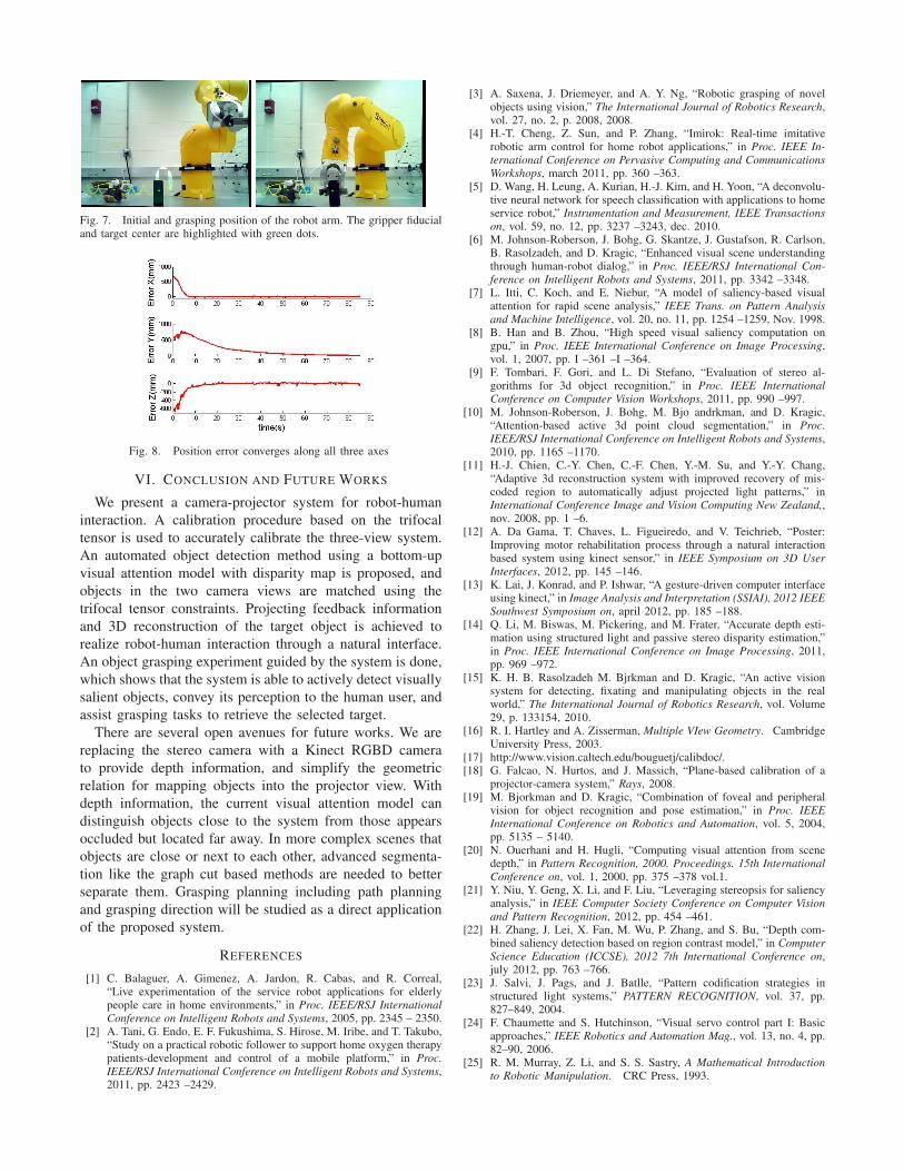
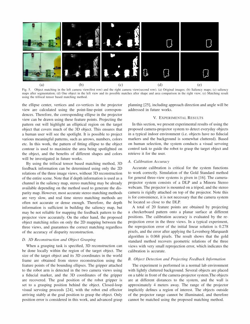
Fig. 7. Initial and grasping position of the robot arm. The gripper fiducialand target center are highlighted with green dots.
Fig. 8. Position error converges along all three axes
VI. CONCLUSION AND FUTURE WORKS
We present a camera-projector system for robot-human
interaction. A calibration procedure based on the trifocal
tensor is used to accurately calibrate the three-view system.
An automated object detection method using a bottom-up
visual attention model with disparity map is proposed, and
objects in the two camera views are matched using the
trifocal tensor constraints. Projecting feedback information
and 3D reconstruction of the target object is achieved to
realize robot-human interaction through a natural interface.
An object grasping experiment guided by the system is done,
which shows that the system is able to actively detect visually
salient objects, convey its perception to the human user, and
assist grasping tasks to retrieve the selected target.
There are several open avenues for future works. We are
replacing the stereo camera with a Kinect RGBD camera
to provide depth information, and simplify the geometric
relation for mapping objects into the projector view. With
depth information, the current visual attention model can
distinguish objects close to the system from those appears
occluded but located far away. In more complex scenes that
objects are close or next to each other, advanced segmenta-
tion like the graph cut based methods are needed to better
separate them. Grasping planning including path planning
and grasping direction will be studied as a direct application
of the proposed system.
REFERENCES
[1] C. Balaguer, A. Gimenez, A. Jardon, R. Cabas, and R. Correal,“Live experimentation of the service robot applications for elderlypeople care in home environments,” in Proc. IEEE/RSJ International
Conference on Intelligent Robots and Systems, 2005, pp. 2345 – 2350.[2] A. Tani, G. Endo, E. F. Fukushima, S. Hirose, M. Iribe, and T. Takubo,
“Study on a practical robotic follower to support home oxygen therapypatients-development and control of a mobile platform,” in Proc.
IEEE/RSJ International Conference on Intelligent Robots and Systems,2011, pp. 2423 –2429.
[3] A. Saxena, J. Driemeyer, and A. Y. Ng, “Robotic grasping of novelobjects using vision,” The International Journal of Robotics Research,vol. 27, no. 2, p. 2008, 2008.
[4] H.-T. Cheng, Z. Sun, and P. Zhang, “Imirok: Real-time imitativerobotic arm control for home robot applications,” in Proc. IEEE In-
ternational Conference on Pervasive Computing and Communications
Workshops, march 2011, pp. 360 –363.[5] D. Wang, H. Leung, A. Kurian, H.-J. Kim, and H. Yoon, “A deconvolu-
tive neural network for speech classification with applications to homeservice robot,” Instrumentation and Measurement, IEEE Transactions
on, vol. 59, no. 12, pp. 3237 –3243, dec. 2010.[6] M. Johnson-Roberson, J. Bohg, G. Skantze, J. Gustafson, R. Carlson,
B. Rasolzadeh, and D. Kragic, “Enhanced visual scene understandingthrough human-robot dialog,” in Proc. IEEE/RSJ International Con-
ference on Intelligent Robots and Systems, 2011, pp. 3342 –3348.[7] L. Itti, C. Koch, and E. Niebur, “A model of saliency-based visual
attention for rapid scene analysis,” IEEE Trans. on Pattern Analysis
and Machine Intelligence, vol. 20, no. 11, pp. 1254 –1259, Nov. 1998.[8] B. Han and B. Zhou, “High speed visual saliency computation on
gpu,” in Proc. IEEE International Conference on Image Processing,vol. 1, 2007, pp. I –361 –I –364.
[9] F. Tombari, F. Gori, and L. Di Stefano, “Evaluation of stereo al-gorithms for 3d object recognition,” in Proc. IEEE International
Conference on Computer Vision Workshops, 2011, pp. 990 –997.[10] M. Johnson-Roberson, J. Bohg, M. Bjo andrkman, and D. Kragic,
“Attention-based active 3d point cloud segmentation,” in Proc.
IEEE/RSJ International Conference on Intelligent Robots and Systems,2010, pp. 1165 –1170.
[11] H.-J. Chien, C.-Y. Chen, C.-F. Chen, Y.-M. Su, and Y.-Y. Chang,“Adaptive 3d reconstruction system with improved recovery of mis-coded region to automatically adjust projected light patterns,” inInternational Conference Image and Vision Computing New Zealand,,nov. 2008, pp. 1 –6.
[12] A. Da Gama, T. Chaves, L. Figueiredo, and V. Teichrieb, “Poster:Improving motor rehabilitation process through a natural interactionbased system using kinect sensor,” in IEEE Symposium on 3D User
Interfaces, 2012, pp. 145 –146.[13] K. Lai, J. Konrad, and P. Ishwar, “A gesture-driven computer interface
using kinect,” in Image Analysis and Interpretation (SSIAI), 2012 IEEE
Southwest Symposium on, april 2012, pp. 185 –188.[14] Q. Li, M. Biswas, M. Pickering, and M. Frater, “Accurate depth esti-
mation using structured light and passive stereo disparity estimation,”in Proc. IEEE International Conference on Image Processing, 2011,pp. 969 –972.
[15] K. H. B. Rasolzadeh M. Bjrkman and D. Kragic, “An active visionsystem for detecting, fixating and manipulating objects in the realworld,” The International Journal of Robotics Research, vol. Volume29, p. 133154, 2010.
[16] R. I. Hartley and A. Zisserman, Multiple VIew Geometry. CambridgeUniversity Press, 2003.
[17] http://www.vision.caltech.edu/bouguetj/calibdoc/.[18] G. Falcao, N. Hurtos, and J. Massich, “Plane-based calibration of a
projector-camera system,” Rays, 2008.[19] M. Bjorkman and D. Kragic, “Combination of foveal and peripheral
vision for object recognition and pose estimation,” in Proc. IEEE
International Conference on Robotics and Automation, vol. 5, 2004,pp. 5135 – 5140.
[20] N. Ouerhani and H. Hugli, “Computing visual attention from scenedepth,” in Pattern Recognition, 2000. Proceedings. 15th International
Conference on, vol. 1, 2000, pp. 375 –378 vol.1.[21] Y. Niu, Y. Geng, X. Li, and F. Liu, “Leveraging stereopsis for saliency
analysis,” in IEEE Computer Society Conference on Computer Vision
and Pattern Recognition, 2012, pp. 454 –461.[22] H. Zhang, J. Lei, X. Fan, M. Wu, P. Zhang, and S. Bu, “Depth com-
bined saliency detection based on region contrast model,” in Computer
Science Education (ICCSE), 2012 7th International Conference on,july 2012, pp. 763 –766.
[23] J. Salvi, J. Pags, and J. Batlle, “Pattern codification strategies instructured light systems,” PATTERN RECOGNITION, vol. 37, pp.827–849, 2004.
[24] F. Chaumette and S. Hutchinson, “Visual servo control part I: Basicapproaches,” IEEE Robotics and Automation Mag., vol. 13, no. 4, pp.82–90, 2006.
[25] R. M. Murray, Z. Li, and S. S. Sastry, A Mathematical Introduction
to Robotic Manipulation. CRC Press, 1993.