a motion capture system based on natural interaction...
TRANSCRIPT
A Motion Capture System Based on Natural Interaction DevicesMaster of Science Thesis in Interaction Design And Technologies
George S. Fahim
Department of Applied Information TechnologyCHALMERS UNIVERSITY OF TECHNOLOGYGothenburg, Sweden, 2012
A Motion Capture System Based on Natural Interaction Devices
George S. Fahim
Department of Applied Information TechnologyCHALMERS UNIVERSITY OF TECHNOLOGY
Gothenburg, Sweden, 2012
The Author grants to Chalmers University of Technology and University of Gothenburg the non-exclusive right to publish the Work electronically and in a non-commercial purpose make it accessible on the Internet. The Author warrants that he is the author to the Work, and warrants that the Work does not contain text, pictures or other material that violates copyright law.
The Author shall, when transferring the rights of the Work to a third party (for example a publisher or a company), acknowledge the third party about this agreement. If the Author has signed a copyright agreement with a third party regarding the Work, the Author warrants hereby that he has obtained any necessary permission from this third party to let Chalmers University of Technology and University of Gothenburg store the Work electronically and make it accessible on the Internet.
A Motion Capture System Based on Natural Interaction Devices
George S. Fahim
© GEORGE S. FAHIM , FEBRUARY 2012.
Examiner: Olof Torgersson
Chalmers University of TechnologyDepartment of Applied Information TechnologySE-41296 GöteborgSwedenTelephone + 46 (0)31-772 1000
Cover:An illustration of the motion capturing process.
Department of Applied Information TechnologyGothenburg, Sweden January 2012
Abstract
Abstract
This thesis investigated the feasibility of building a simple and affordable motion capturing system. A pre-study was made to understand the potential uses and benefits of Natural Interaction based devices and accordingly, the Kinect sensor was used as an input device to the system. The implementation of the system was based on a client/server model. The client implemented in C++, was responsible for fetching the skeletal tracking data from the Kinect sensor, and the server, which resided in two different animation programs, implemented in Python and was responsible for making the skeletal data comprehensible to the animators who are the users of the system. The server program was extended to allow the capturing, recording, and retargeting of the motion data acquired through the sensor. The communication between the client and server was based on the Open Sound Control protocol. Furthermore, the system was tested for both functionality and usability by a sample from the target users.
Keywords: Motion capture, Kinect, Natural Interaction, 3D Animation, Autodesk Maya, Autodesk Motionbuilder, C++, Python, OSC
IV
Table of Contents
Table of Contents
List of Abbreviations.......................................................................................................................VII1. Introduction..................................................................................................................................12. Methodology.................................................................................................................................2
2.1 Process overview.............................................................................................................................22.2 Methods used..................................................................................................................................3
3. Background Research....................................................................................................................43.1 General Information Gathering.......................................................................................................43.2 Investigation of similar projects......................................................................................................53.3 Literature review.............................................................................................................................73.4 Conceptualizing the idea................................................................................................................83.5 Formulating the research problem..................................................................................................9
4. Implementation Alternatives Research .......................................................................................104.1 Further research into MoCap.......................................................................................................104.2 Possible devices investigation.......................................................................................................104.3 The OpenNI framework.................................................................................................................104.4 The Kinect SDK...............................................................................................................................114.5 OpenNI framework versus Kinect SDK..........................................................................................124.6 The limitations stated....................................................................................................................14
5. User Requirements Elicitation .....................................................................................................155.1 Target user definition....................................................................................................................155.2 Determining user needs................................................................................................................155.3 Features and architecture decided ..............................................................................................16
6. Client Module Development........................................................................................................177.Networking Module Development................................................................................................19
7.1 Deciding the networking protocol.................................................................................................197.2 The OSC protocol...........................................................................................................................197.3 OSC message syntax and structure...............................................................................................207.4 building the OSC messages............................................................................................................207.5 receiving the OSC messages..........................................................................................................21
8. Server Module Development.......................................................................................................238.1 The server script............................................................................................................................238.2 MEL versus Python........................................................................................................................248.3 Server application in details..........................................................................................................24
V
Table of Contents
8.4 The server's GUI............................................................................................................................258.5 Porting server code to MotionBuilder...........................................................................................268.6 MotionBuilder's script limitations.................................................................................................27
9. System Integration Testing...........................................................................................................2810. Testing Usability ........................................................................................................................30
10.1 Video tests...................................................................................................................................3010.2 Evaluation walkthrough...............................................................................................................31
11. Conclusions...............................................................................................................................3311.1 Answer to research questions.....................................................................................................33
12. Discussion..................................................................................................................................3412.1 Evaluation....................................................................................................................................3412.2 Comparison with similar projects................................................................................................3412.3 Future work.................................................................................................................................35
References......................................................................................................................................36
VI
List of Abbreviations
List of Abbreviations
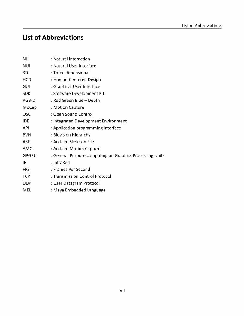
NI : Natural InteractionNUI : Natural User Interface3D : Three dimensionalHCD : Human-Centered DesignGUI : Graphical User InterfaceSDK : Software Development KitRGB-D : Red Green Blue – DepthMoCap : Motion CaptureOSC : Open Sound ControlIDE : Integrated Development EnvironmentAPI : Application programming InterfaceBVH : Biovision Hierarchy ASF : Acclaim Skeleton FileAMC : Acclaim Motion CaptureGPGPU : General Purpose computing on Graphics Processing UnitsIR : InfraRed FPS : Frames Per SecondTCP : Transmission Control ProtocolUDP : User Datagram ProtocolMEL : Maya Embedded Language
VII
1. Introduction
1. Introduction
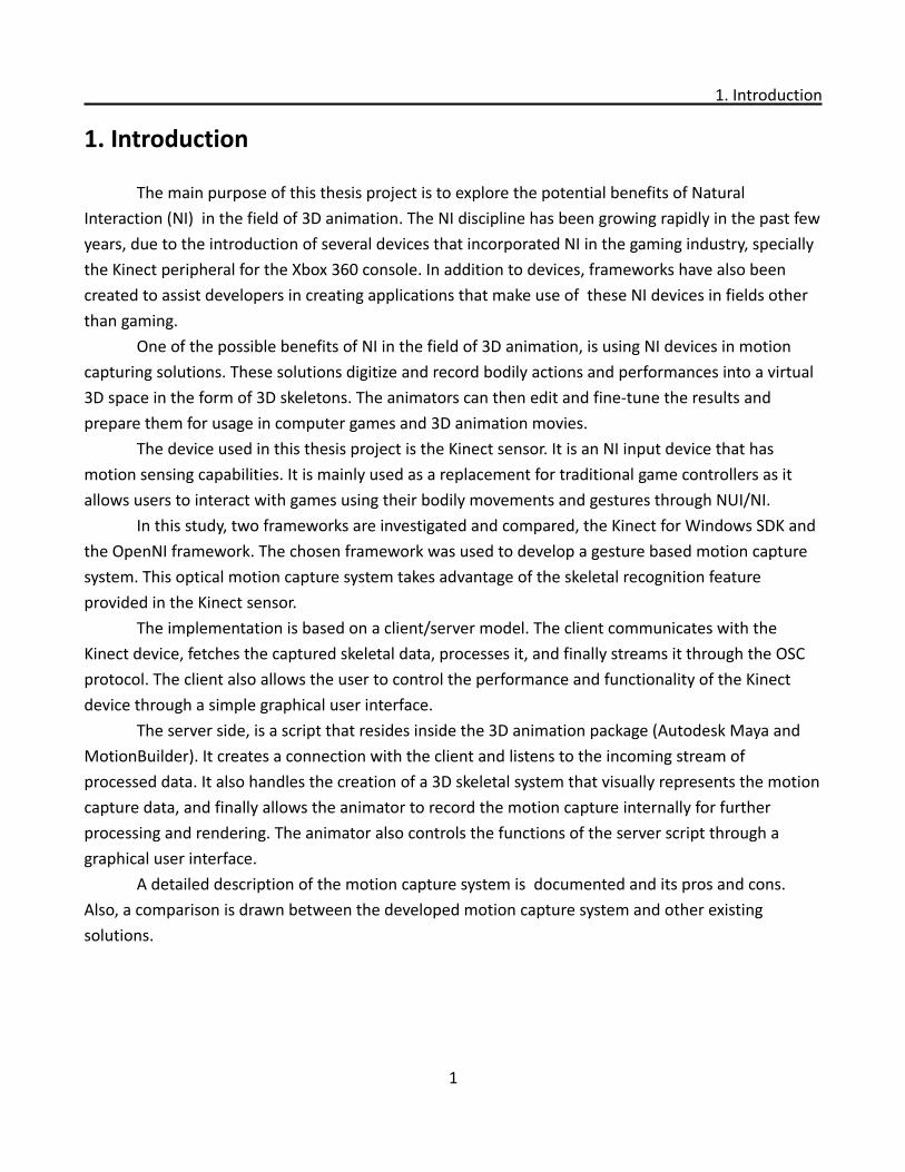
The main purpose of this thesis project is to explore the potential benefits of Natural Interaction (NI) in the field of 3D animation. The NI discipline has been growing rapidly in the past few years, due to the introduction of several devices that incorporated NI in the gaming industry, specially the Kinect peripheral for the Xbox 360 console. In addition to devices, frameworks have also been created to assist developers in creating applications that make use of these NI devices in fields other than gaming.
One of the possible benefits of NI in the field of 3D animation, is using NI devices in motion capturing solutions. These solutions digitize and record bodily actions and performances into a virtual 3D space in the form of 3D skeletons. The animators can then edit and fine-tune the results and prepare them for usage in computer games and 3D animation movies.
The device used in this thesis project is the Kinect sensor. It is an NI input device that has motion sensing capabilities. It is mainly used as a replacement for traditional game controllers as it allows users to interact with games using their bodily movements and gestures through NUI/NI.
In this study, two frameworks are investigated and compared, the Kinect for Windows SDK and the OpenNI framework. The chosen framework was used to develop a gesture based motion capture system. This optical motion capture system takes advantage of the skeletal recognition feature provided in the Kinect sensor.
The implementation is based on a client/server model. The client communicates with the Kinect device, fetches the captured skeletal data, processes it, and finally streams it through the OSC protocol. The client also allows the user to control the performance and functionality of the Kinect device through a simple graphical user interface.
The server side, is a script that resides inside the 3D animation package (Autodesk Maya and MotionBuilder). It creates a connection with the client and listens to the incoming stream of processed data. It also handles the creation of a 3D skeletal system that visually represents the motion capture data, and finally allows the animator to record the motion capture internally for further processing and rendering. The animator also controls the functions of the server script through a graphical user interface.
A detailed description of the motion capture system is documented and its pros and cons. Also, a comparison is drawn between the developed motion capture system and other existing solutions.
1

2. Methodology
2. Methodology
2.1 Process overview
This thesis work falls under the “Design and Creation” research category [1] in which both theory and practice were investigated and researched before designing and implementing the system. Additionally, a human centered design philosophy was adopted and integrated to ensure the usability of the system.
To ensure a streamlined workflow, a general structure for the whole process was built and followed. The structure was mainly based on the ISO 13407 standard “Human-centered design processes for interactive systems”[2]. This standard offers best practices and guidelines in human-centered design. It applies to software products, hardware/software systems, websites, and services. The standard's description can be summarized in the following table[3]:
Four Principles of Human-Centred Design Four Human-Centred Design Activities
active involvement of users understand and specify the context of use
appropriate allocation of function to system and to user
specify user and organisational requirements
iteration of design solutions produce more than one candidate design solution
multi-disciplinary design evaluate designs against requirements
The ISO 13407 standard requires the planning and specification of a human-centered design process. To meet this requirement several HCD methods were investigated, but the “Rational Unified Process iteration cycle”[4] was eventually chosen. This process is iterative in nature which worked seamlessly with the ISO 13407 standard. The process entails dividing the design and testing tasks into iterations instead of the traditional waterfall workflow. Per Kroll the author of this process notes that: "Each iteration also has a well-defined set of objectives and produces a partial working implementation of the final system. And each successive iteration builds on the work of previous iterations to evolve and refine the system until the final product is complete. Early iterations emphasize requirements as well as analysis and design; later iterations emphasize implementation and testing”[4]. The main principles of the “Rational Unified Process iteration cycle” are:
2
2.1 Process overview
1. Build functional prototypes early.2. Divide the detailed design, implementation and test phases into iterations.3. Baseline an executable architecture early on.4. Adopt an iterative and risk-driven management process.
2.2 Methods used
Pre-study: was the initial step in this project, preliminary information was gathered, both theoretical and practical. The aim of the pre-study was to build the adequate knowledge needed before the initiation of the project work. The main activity in the pre-study was reading different research materials and investigating similar projects and previous endeavors to attain a simple and affordable motion capturing solution.
Interviews and Brainstorming: semi-structured interviews took place to understand the user needs. These interviews involved a participant and the interviewer, they discussed the project's scope, limitations, and expectations. Features were generated and discussed through brainstorming activities in which both parties participated. Initially, ideas were not filtered or criticized, but after these sessions, the ideas were evaluated in terms of feasibility and affordance.
Sketching: was the method used to visualize design ideas. In this project sketching was used as a low fidelity prototyping alternative. User interface and interaction flow were sketched using paper and pencil to provide a fast way to evaluate and test the designs for major flaws. For this project sketching was a rapid and reliable alternative to more sophisticated prototyping methods.
Testing: was done at each phase and most of the iterations, for both functionality and usability. User tests were also scheduled and performed to ensure the user's continuing involvement in the process. To reach more potential users a video describing the details of the system was distributed among professional animators, and feedback was given through the internet and social networks.
Evaluation walkthrough: is the process of going step-by-step through a system design and getting reactions from user representatives [5]. A fast yet reliable alternative of Evaluation walkthrough was used, the cognitive jogthrough [6]. This method used video recordings of test sessions instead of filling evaluation sheets.
3
3. Background Research
3. Background Research
3.1 General Information Gathering
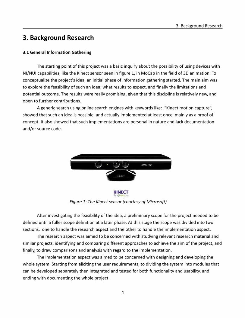
The starting point of this project was a basic inquiry about the possibility of using devices with NI/NUI capabilities, like the Kinect sensor seen in figure 1, in MoCap in the field of 3D animation. To conceptualize the project's idea, an initial phase of information gathering started. The main aim was to explore the feasibility of such an idea, what results to expect, and finally the limitations and potential outcome. The results were really promising, given that this discipline is relatively new, and open to further contributions.
A generic search using online search engines with keywords like: “Kinect motion capture”, showed that such an idea is possible, and actually implemented at least once, mainly as a proof of concept. It also showed that such implementations are personal in nature and lack documentation and/or source code.
After investigating the feasibility of the idea, a preliminary scope for the project needed to be defined until a fuller scope definition at a later phase. At this stage the scope was divided into two sections, one to handle the research aspect and the other to handle the implementation aspect.
The research aspect was aimed to be concerned with studying relevant research material and similar projects, identifying and comparing different approaches to achieve the aim of the project, and finally, to draw comparisons and analysis with regard to the implementation.
The implementation aspect was aimed to be concerned with designing and developing the whole system. Starting from eliciting the user requirements, to dividing the system into modules that can be developed separately then integrated and tested for both functionality and usability, and ending with documenting the whole project.
4
Figure 1: The Kinect sensor (courtesy of Microsoft)
3.1 General Information Gathering
The main limitations discovered at this early stage were mainly the lack of precision in the motion data, the limited number of joints that can be tracked, and the difficulty in calculating the rotation of the tracked joints. It was very beneficial to know these limitations as early as possible to be able to understand the scope and expectations of the end results and their outcome.
3.2 Investigation of similar projects
To proceed further with the initial investigation, existing projects implementing a similar idea were checked. It was extremely hard to find well documented projects not to mention open source projects. In most of the cases what was found was basically a showcase for integrating Kinect's skeletal tracking with a 3D authoring tool. These showcases were either videos or short blog posts, and without source code, helpful information, or even executable files to try them out.
But in some other cases, projects were accompanied by source code or documentation. Examples of these showcases were: Integrating Kinect with Unity 3D engine (source code available)[7], Unreal Development Kit (source code available) [8], Daz studio [9], and Motionbuilder[10].
The first project checked that provided even more useful information was Jasper Brekelmans' personal project: “Brekel Kinect” [10]. It is a piece of software that captures skeleton movement from Kinect and streams it to Motionbuilder, an animation software. This project is closed source, however, Brekelmans provided some information about the drivers and frameworks used, which helped moving the search forward.
Brekel Kinect uses the OpenNI framework and the NITE [11] driver for its implementation, in addition to the Kinect device of course. There is a base application that saves and exports 3D point cloud data that can be used as 3D models, textures, and particle systems in 3D authoring packages. Additionally, the base application can capture and save motion data in the BVH file format. Brekel Kinect also provides a plug-in written specifically for Motionbuilder so that motion data can be streamed in realtime from Kinect to Motionbuilder to control a Motionbuilder character.
One of the limitations of Brekel Kinect is that it doesn't support tracking multiple actors while the Kinect device supports up to two skeletons tracked at the same time. It also inherits the functional limitations of the Kinect device and the OpenNI framework. However, Brekel Kinect has been used by many animators and is widely accepted as a great tool that helps in achieving a faster animation process.
Another slightly different approach towards motion capturing with Kinect was “Radius9 Motion Capture Utility” [12]. It is a side project done at Radius9 consultancy and development company. This software instead of streaming the motion data to a network address and port, it exports it to a file on the hard disk. This project lacks documentation and it is provided as an initial
5
3.2 Investigation of similar projects
Beta version, so it may get updated in the future.“Radius9 Motion Capture Utility“ in its current version works with Kinect and the OpenNI
framework, it provides all the needed drivers in one installer. It allows exporting the motion capture data in both BVH file format and ASF/AMC file formats, and there is no streaming functionality in this application. This project didn't provide the ongoing search with useful information, but it was just another proof of concept on how feasible the idea was and how differently it can be approached.
Commercial products were also included in the research, for example “iPi Desktop Motion Capture” (DMC) [13] software was checked. It is an offline tracking solution that uses both normal 2D cameras and the Kinect device. One needs first to record a video then process it using this application.
The introduction of Kinect capturing to this system is relatively new, but it is supported and well documented. The DMC system is divided into two standalone applications. The first is the “iPi recorder”, which captures the depth data from the Kinect device and saves it to disk. And the second application is the “iPi studio”, which processes the depth data offline and allows the export of processed motion data in various file formats.
This solution uses a modified light-weight version of the original PrimeSense driver. It also uses a proprietary protocol implementation to ensure faster processing, and as this solution uses the GPGPU technique it requires a decent graphics card for better performance.
This solution inherits some of the limitations of the Kinect device, even though it doesn't use its skeletal tracking feature, and it also needs the floor to be fully visible during the whole recording session. Another limitation is that it needs the background to be recorded first without the actor for some seconds first before the capturing happens. On the other hand, since this solution is not realtime, and can make use of heavy processing and computation, it provides higher quality data and more precise motion capture. It is a really useful solution even though it is costly and not easy or straight forward to use.
Another commercial product checked was the Organic Motion solution[14], this is a realtime solution based on 2D cameras input, this solution targets big studios with space and funds capabilities that are beyond this project's scope.
However, the company's R&D team is working on integrating Kinect as an input device to their solution[15]. Kinect in this case provides the solution with depth data while other normal 2D cameras (as simple as web cameras) provide the system with the missing data occluded from the Kinect field of view. Thus creating a full 3D real time tracking solution that is based on their proprietary tracking software and the integrated data from the cameras and the Kinect sensor.
6
3.3 Literature review
3.3 Literature review
Despite the recent history of the Kinect device, a lot of researchers were encouraged to investigate the different ways of using it, which created a decent amount of research projects and papers covering a broad spectrum of applications. However, before delving into the the Kinect based applications, there was a need to understand the Kinect platform itself, and motion capturing specifications and its process.
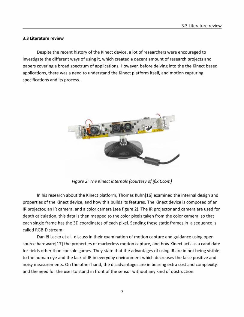
In his research about the Kinect platform, Thomas Kühn[16] examined the internal design and properties of the Kinect device, and how this builds its features. The Kinect device is composed of an IR projector, an IR camera, and a color camera (see figure 2). The IR projector and camera are used for depth calculation, this data is then mapped to the color pixels taken from the color camera, so that each single frame has the 3D coordinates of each pixel. Sending these static frames in a sequence is called RGB-D stream.
Daniël Lacko et al. discuss in their examination of motion capture and guidance using open source hardware[17] the properties of markerless motion capture, and how Kinect acts as a candidate for fields other than console games. They state that the advantages of using IR are in not being visible to the human eye and the lack of IR in everyday environment which decreases the false positive and noisy measurements. On the other hand, the disadvantages are in bearing extra cost and complexity, and the need for the user to stand in front of the sensor without any kind of obstruction.
7
Figure 2: The Kinect internals (courtesy of ifixit.com)
3.3 Literature review
When it comes to Kinect based applications, the initial research initiatives were mainly concerned with making use of the raw data provided by the device namely the RGB-D stream, starting from body parts detection and tracking [18], to pose detection [19], and ending with partial skeletal tracking [20] and human activity detection in unstructured environments [21].
What is common in these research initiatives is that they all try to achieve realtime calculations but with different implementation methods. Iason Oikonomidis et al. [18] approach hand tracking as an optimization problem, they make extensive use of optimization algorithms and GPU processing. They take the depth data, analyze it, segment it, and finally apply it on a virtual hand model at a speed of 15 FPS. In a similar endeavor, Microsoft Research Cambridge group [19] proposed a different technique for the detection and recognition of the whole body parts at a frame rate of 200 FPS.
Skeletal tracking was tried even before the introduction of the internal tracking system available in the official drivers and frameworks. Abhishek Kar [20] introduced a novel algorithm for upper body skeletal tracking that runs at 10 FPS. It had some limitations and accuracy problems that were overcome in the algorithms provided in the official frameworks.
After the introduction of official frameworks, drivers, and software development kit, it became easier for researchers to use Kinect in many more applications, for example Dutta [22] investigated the possibility of using Kinect in the ergonomics field, he proved that Kinect can be used as a portable 3D motion capture system for performing ergonomic assessments.
Another field of application is education, several researchers [23][24] worked on evaluating the use of Kinect for educational purposes. They agreed on the significant number of opportunities that Kinect opens in the field of education and education technology by the use of interactivity and natural user interface. The most recent researches involved extending the features of Kinect in Augmented reality [25], games animations [26], and hardware integration [27].
3.4 Conceptualizing the idea
The information gathered so far were enough to transform the project idea into a concept. The concept was building a simple and affordable markerless motion capture solution using the data provided by Kinect namely the skeletal tracking data, then streaming these data into a 3D authoring package to facilitate the animators tasks related to human or humanoid animations.
8

3.5 Formulating the research problem
3.5 Formulating the research problem
The research problem was centered around answering these questions: • How one can build a simple and affordable motion capture system?
◦ what are the different approaches to create an optical motion capture system using NUI based devices? And what is the difference between these approaches?
◦ How can a Kinect based MoCap be built in the most straightforward way?
9
4. Implementation Alternatives Research
4. Implementation Alternatives Research
4.1 Further research into MoCap
To take the research a step further, a thorough investigation was made, to understand what motion capture really is.
Motion capture is a process by which analog body movements are recorded and transformed into the digital world. The main purpose of motion capture is to use the captured movements to drive a virtual character in a 3D space. This process involves creating a virtual skeletal system that mimics the human skeleton. The motion data is recorded on the virtual skeleton for further use either in realtime applications or non realtime ones.
There are two categories of motion capture solutions: optical motion capture, and non-optical motion capture. The optical capture category is further divided into two divisions: sensor (marker) based, and markerless optical motion capture. Kinect falls in the latter category, markerless motion capture, because it doesn't need physical sensors but it relies on processing image and depth streams.
4.2 Possible devices investigation
Even though Kinect was the main candidate device in this project, other alternatives were explored. PlayStation Eye camera was the least potential candidate. It is a camera with added capabilities like gesture recognition and head tracking, it also implements depth data. However, it lacks full skeletal tracking and Microsoft Windows support.
Another sensor checked was the SoftKinetic DepthSense camera, which is strikingly similar to Kinect in shape and features, however, this one too lacked the skeletal tracking feature. And also, it is only available as an engineering sample with no widespread usage.
The last sensor checked was the Asus Xtion PRO which is basically identical to the Kinect device but works only with the OpenNI framework.
4.3 The OpenNI framework
Before the release of any official drivers or frameworks, there were crowd-sourced initiatives to connect the Kinect to PCs like the OpenKinect project[28]. OpenKinect and similar projects lacked official support and were considered only as hacks. However, the actual rise of the NI industry started with the establishment of the OpenNI organization in November 2010.
“The OpenNI organization is an industry-led, not-for-profit organization formed to certify and
10
4.3 The OpenNI framework
promote the compatibility and interoperability of Natural Interaction devices, applications and middleware. One of the OpenNI organization goals is to accelerate the introduction of Natural Interaction applications into the marketplace. “[29]
OpenNI is the organization that developed and supports the OpenNI framework. They define it as:
“a multi-language, cross-platform framework that defines APIs for writing applications utilizing Natural Interaction. OpenNI APIs are composed of a set of interfaces for writing NI applications. The main purpose of OpenNI is to form a standard API that enables communication with both:
• Vision and audio sensors (the devices that ‘see’ and ‘hear’ the figures and their surroundings.)
• Vision and audio perception middleware (the software components that analyze the audio and visual data that is recorded from the scene, and comprehend it). For example, software that receives visual data, such as an image, returns the location of the palm of a hand detected within the image.
OpenNI supplies a set of APIs to be implemented by the sensor devices, and a set of APIs to be implemented by the middleware components. By breaking the dependency between the sensor and the middleware, OpenNI’s API enables applications to be written and ported with no additional effort to operate on top of different middleware modules (“write once, deploy everywhere”). OpenNI's API also enables middleware developers to write algorithms on top of raw data formats, regardless of which sensor device has produced them, and offers sensor manufacturers the capability to build sensors that power any OpenNI compliant application.
The OpenNI standard API enables natural-interaction application developers to track real-life (3D) scenes by utilizing data types that are calculated from the input of a sensor (for example, representation of a full body, representation of a hand location, an array of the pixels in a depth map and so on). Applications can be written regardless of the sensor or middleware providers.” [30]
4.4 The Kinect SDK
Kinect SDK on the other hand is developed and supported by Microsoft and is built specifically for the Kinect sensor. It is defined as: “a starter kit for software developers, to make it easier for them to create rich experiences using Kinect sensor technology on their system. It is intended for
11
4.4 The Kinect SDK
experimentation and exploration ”[31]. The Kit includes the needed drivers, the APIs, and device interfaces in one executable file. Programs can be developed in C++, C#, or Visual Basic programming languages.
The SDK provides the native and managed APIs and the tools that are needed to develop Kinect enabled applications for Windows only. Developing Kinect enabled applications with this SDK is essentially the same as developing other Windows applications, except that the SDK provides support for the features of the Kinect sensor (color images, depth images, audio, skeletal data, etc.).
4.5 OpenNI framework versus Kinect SDK
Before the introduction of the Kinect SDK, Almost all developers interested in developing NI applications were using the OpenNI framework. However, after the SDK's release developers started comparing the two approaches trying to find the points of strength and weakness in both. The comparison provided here was conducted with the aid of several resources, the official documentation of each API[30][32] and industry driven resources [33][34][35] which are mainly efforts done by developers trying to figure out the pros and cons in each API.
The first point of comparison is platform dependency. The OpenNI framework is cross platform, a developer can program his/her work on one platform and it can be easily ported to other platforms. While the Kinect SDK is built to work on Windows platform only. Its API dependence makes it not suitable for porting to other platforms. In addition, the OpenNI framework offers native APIs for both Windows and Linux platforms. A drawback in the OpenNI framework is that it is only tailored to work on x86 systems, while the Kinect SDK works on both x86 and x64 systems natively.
Another point of comparison is the ease of use. To start developing applications with OpenNI, one needs three different packages to install. Also, to make it work with the Kinect sensor a license string needs to be acquired first that define its vendor and properties. Such steps are mandatory to ensure interoperability of the API and middleware. On the other hand, the Kinect SDK is available bundled with the needed drivers in one installer file, this diminishes the chances of any conflict while with the OpenNI framework conflicts can happen. Additionally, the Kinect SDK is simple to start developing with, as it offers a straightforward way to handle callbacks specially with the managed API. But since OpenNI is a more generic framework, it requires a higher learning curve. The Kinect SDK also offers better documentation and more samples to learn from.
When it comes to the spread of use, the OpenNI framework has a clear edge. The OpenNI framework was released more than six months before the Kinect SDK. In that period a lot of projects were developed using OpenNI. The OpenNI framework became an industry standard even before the release of the Kinect SDK. Its license also allows commercial use, while the Kinect SDK is only in its beta stage and allows only non-commercial use. In addition to that, the OpenNI framework is
12
4.5 OpenNI framework versus Kinect SDK
extensible since it is an open source project, this gives room for 3rd party extensions and add-ons. While the Kinect SDK is not extensible and Microsoft supports only the current and existing features. Another limitation facing the Kinect SDK is that it supports only the Kinect sensor, while the OpenNI framework supports Kinect and other devices from several vendors.
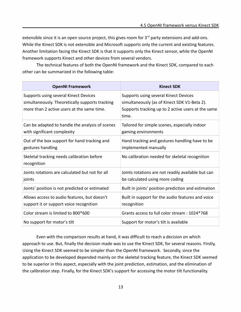
The technical features of both the OpenNI framework and the Kinect SDK, compared to each other can be summarized in the following table:
OpenNI Framework Kinect SDK
Supports using several Kinect Devices simultaneously. Theoretically supports tracking more than 2 active users at the same time.
Supports using several Kinect Devices simultaneously (as of Kinect SDK V1-Beta 2). Supports tracking up to 2 active users at the same time.
Can be adapted to handle the analysis of scenes with significant complexity
Tailored for simple scenes, especially indoor gaming environments
Out of the box support for hand tracking and gestures handling
Hand tracking and gestures handling have to be implemented manually
Skeletal tracking needs calibration before recognition
No calibration needed for skeletal recognition
Joints rotations are calculated but not for all joints
Joints rotations are not readily available but can be calculated using more coding
Joints' position is not predicted or estimated Built in joints' position prediction and estimation
Allows access to audio features, but doesn't support it or support voice recognition
Built in support for the audio features and voice recognition
Color stream is limited to 800*600 Grants access to full color stream : 1024*768
No support for motor's tilt Support for motor's tilt is available
Even with the comparison results at hand, it was difficult to reach a decision on which
approach to use. But, finally the decision made was to use the Kinect SDK, for several reasons. Firstly, Using the Kinect SDK seemed to be simpler than the OpenNI framework. Secondly, since the application to be developed depended mainly on the skeletal tracking feature, the Kinect SDK seemed to be superior in this aspect, especially with the joint prediction, estimation, and the elimination of the calibration step. Finally, for the Kinect SDK's support for accessing the motor tilt functionality.
13
4.5 OpenNI framework versus Kinect SDK
Another issue that was considered to be important for the future use of the Kinect sensor was that using any other API with the Kinect sensor voids the device's warranty. In Microsoft's eyes, any API other than the Kinect SDK is considered a hack, even the OpenNI framework, which is considered everywhere else as an industry standard.
It is worth mentioning that a C++ wrapper was recently created to manage working with both solutions, it is still in its initial development phase, but it can be a promising piece of code [36]. Its features include:
• Modern C++ wrapper for transparent use of OpenNI and Microsoft Kinect SDK with same API• Support for multiple devices• High Performance via multithreading• Support for all major available functionalities of both Kinect SDK and OpenNI• Samples for libCinder, OpenFrameworks and GLUT/OpenGL• C++ exception handling and error logging (file, console, non-verbose)• Doxygen documentation• Ongoing development (recording/playback, c3d format for animation software import)
4.6 The limitations stated
From the drawn comparison, it became known that there were limitations facing the implementation of the motion capturing system using the Kinect sensor. These limitations were:
• The implementation can support bipeds (human or humanoid characters) only .• The maximum number of actors who can be tracked simultaneously is two.• The number of joints tracked per actor is fixed at twenty joints.• Only the joints' positions are calculated, joints' rotations are not calculated.• The implementation will not support facial recognition or animation.• Actors fingers can not be tracked.
14
5. User Requirements Elicitation
5. User Requirements Elicitation
Building on the preliminary scope that was shaped earlier, the scope was further defined. The Kinect SDK was chosen as the API to use. The limitations of the implementation were determined. A strict yet realistic schedule was put into action. Then the project proceeded to the design and implementation part of this thesis work, and its initial phase was the elicitation of user requirements.
5.1 Target user definition
A prior step to the requirements elicitation phase was to define the target user of the proposed system. The target user was defined as follows: “A computer user with knowledge of the 3D production pipeline in general, and with specific knowledge of the animation phase, specially character animation. He/she needs to be familiar with Autodesk Maya and/or MotionBuilder and their components. Basic knowledge of scripting in these environments would be an advantage, but not a requirement.”
5.2 Determining user needs
After defining the target user, it was important to find actual potential users with such characteristics, and getting their input/feedback to shape the whole design and implementation phase. Two initial interviews took place to discuss the product scope and the user's needs and expectations. These interviews were informal in nature and they ended in being what can be described more precisely as brainstorming sessions.
In the beginning of the interview the interviewee was presented with the project's idea and the current limitations. Then a discussion took place regarding what features were desired to be available in the system. The interviews resulted in eliciting these requirements:
• An automated skeleton creation tool• Access to the internal functionality available in the Kinect sensor (motor, smoothing algorithm) • A straightforward way to control the flow of motion data (locally and through a network)• An automated tool to record and plot the animation on the created skeleton(s)
15
5.3 Features and architecture decided
5.3 Features and architecture decided
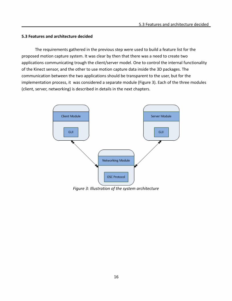
The requirements gathered in the previous step were used to build a feature list for the proposed motion capture system. It was clear by then that there was a need to create two applications communicating trough the client/server model. One to control the internal functionality of the Kinect sensor, and the other to use motion capture data inside the 3D packages. The communication between the two applications should be transparent to the user, but for the implementation process, it was considered a separate module (Figure 3). Each of the three modules (client, server, networking) is described in details in the next chapters.
16
Figure 3: Illustration of the system architecture
6. Client Module Development
6. Client Module Development
The client application is the application responsible for the communication with the Kinect sensor, fetching the skeletal tracking data, and presenting it to the user. Also, the user controls the functionality of the sensor, and the quality of the tracking using the client application through a GUI. The client application was written in C++ programming language.
The first step in this phase was to check if there were any helpful libraries that could facilitate the development of the client application and at the same time work seamlessly with the Kinect SDK. The Kinect SDK itself provided a sample application that could be used a starting foundation and further developed as it provided the basic functionality needed for this project. However, there was another better alternative, a wrapper code built by Stephen Schieberl[37]. This wrapper was written to work with the Cinder library[38], which is an open source C++ library for creative programming. Using the Cinder library was not planned in the beginning, however, it acted as great candidate for the client development, as it provided tools for handling multithreading, eliminating memory leaks, and OpenGL integration. So, the decision was made to use the Cinder library with the Kinect wrapper provided by Stephen Schieberl.
The core functionality was already available in the wrapper code, what needed modification was:
• removing the audio features, • adding the events that control the motor, • adding the access to the internal smoothing algorithm, and• modifying the GUI: creating the Kinect menu, modifying and rearranging the various
display areas. The client was designed to be event based. There were event handlers to handle the initiation of the device, its shutting down, and its update events. For the application to work, first the device is initialized and started, the initial tilt angle of the device is stored, and the environment is set up to start the capturing process. In the update event the device is instructed to check if there are skeletons to be tracked, if it is the case, the skeletal data is drawn to the screen. Also in the update event, the RGB and depth data of each frame are fetched from the sensor and drawn to the screen. The update event also handles the changes in any of the attributes controlled by the user, and accordingly change the device or the application settings to perform the desired action.
In the shutting down event, the capturing is stopped, the used skeleton objects are deleted, the used buffers are deleted, and finally the sensor itself is shut down and unlocked.
After all the features of the client were implemented, they were tested if they produce the
17
6. Client Module Development
desired actions or not. Bugs were discovered and fixed through several experimental runs and tests. It was difficult to test the attributes of the smoothing algorithm built in the SDK as the differences were minimal. However, the prediction and correction properties proved to be working as expected. Additionally, the features were evaluated against the user requirements to ensure that the application fulfills all the required tasks demanded by the target users in the previous requirement elicitation phase.
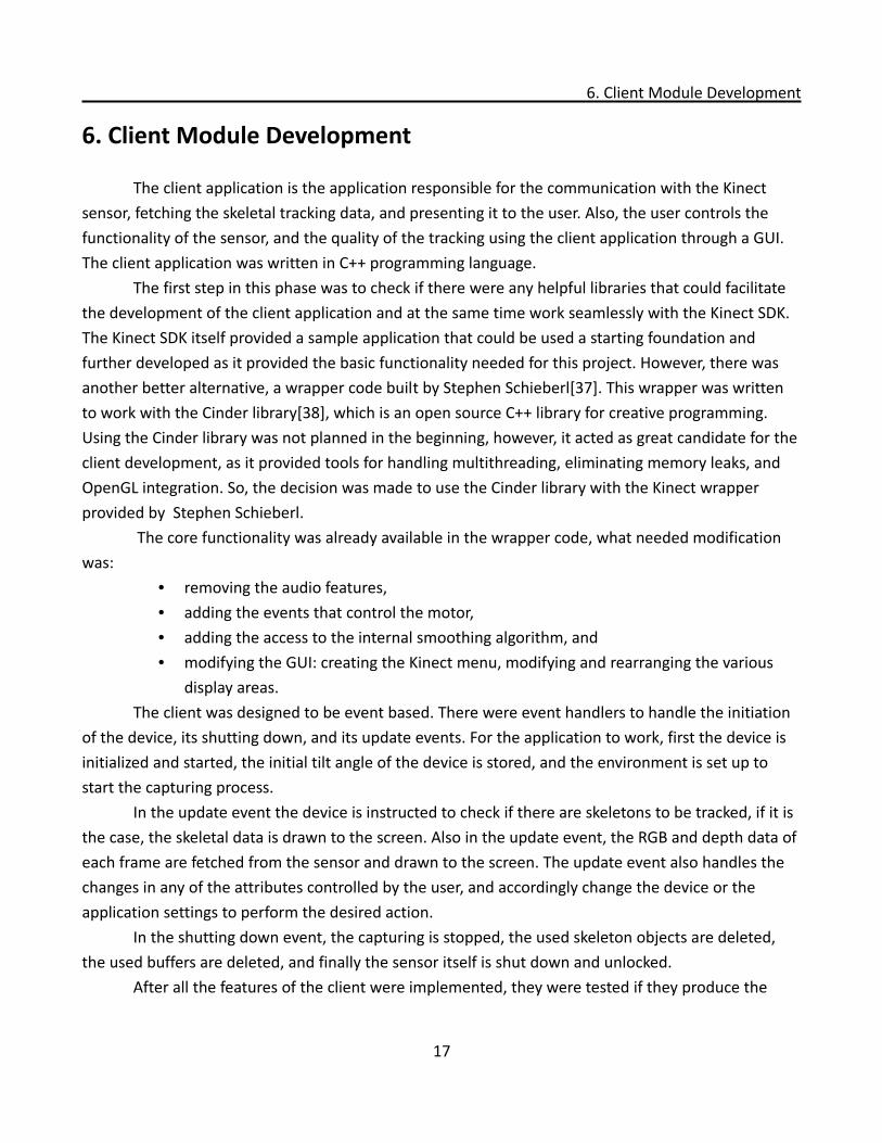
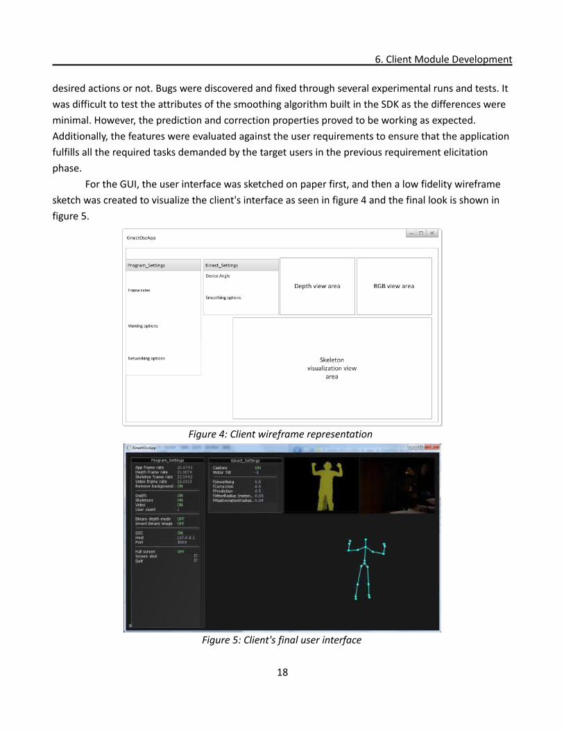
For the GUI, the user interface was sketched on paper first, and then a low fidelity wireframe sketch was created to visualize the client's interface as seen in figure 4 and the final look is shown in figure 5.
18
Figure 4: Client wireframe representation
Figure 5: Client's final user interface
7.Networking Module Development
7.Networking Module Development
The networking module was designed to be the communication link between the server and the client applications. The sender code was written in C++ and the receiver code was written in Python. Having a networking module allows the system to be used either locally on one computer using the loop-back address (the local host) or on two computers connected through a local area network.
7.1 Deciding the networking protocol
There were several alternatives to choose from regarding which protocol to apply as the communication protocol. There were the traditional TCP and UDP protocols, and there were other less popular choices like the OSC protocol[39], which was eventually chosen. The main advantage of the OSC protocol is the ease and flexibility of implementation. The other more traditional protocols were more complicated to implement given the limited knowledge of the researcher in socket programming.
7.2 The OSC protocol
The OSC protocol was developed and continues to be maintained by the Center for New Music and Audio Technologies, a research center within the University of California, Berkeley[40]. It was initially created as a networking protocol between electronic musical instruments, but developers in other disciplines took advantage of its simplicity in their work, and it is now used as a networking solution in a broader spectrum of uses other than musical instruments. Its features include[41]:
• Open-ended, dynamic, URL-style symbolic naming scheme• Symbolic and high-resolution numeric argument data• Pattern matching language to specify multiple recipients of a single message• High resolution time tags• "Bundles" of messages whose effects must occur simultaneously• Query system to dynamically find out the capabilities of an OSC server and get
documentationThe OSC protocol is implemented in a multitude of programming languages in the form of
libraries, the ones used in this project were the C++ library (which was also included in the Cinder library), and the Python library (the simple OSC implementation). The protocol and its implementations were fairly straightforward, but the data packets that needed to be transmitted in
19
7.2 The OSC protocol
this project had to follow a specific structure, the OSC specification calls the data packets “messages” and they are considered the basic unit of transmission.
7.3 OSC message syntax and structure
According to the OSC protocol specification, the application that sends OSC packets is called OSC Client (or sender application), and the application that receives the OSC packets is called OSC server (or receiver application), hence came the naming of this project's modules.
At the client side where the messages are formed and sent, OSC packets (messages) must be built to include three different contents: OSC address pattern, OSC type tag string, and the OSC argument(s). The OSC address designates the identity of each message, and on the server side there should be a message handler for each specific address as it will be explained later. The OSC type tag specifies the data type of the arguments and also the total number of arguments. The third content of the OSC message, the OSC argument(s) is the actual data sent through this protocol.
7.4 building the OSC messages
In this implementation, the OSC addresses were used to define the actors and their tracked joints. The system supports two actors each has twenty joints tracked, so the total number of addresses was 40 addresses. The pattern of the used addresses followed this structure:
“/Device name/Skeleton/Skeleton ID/Joint name”
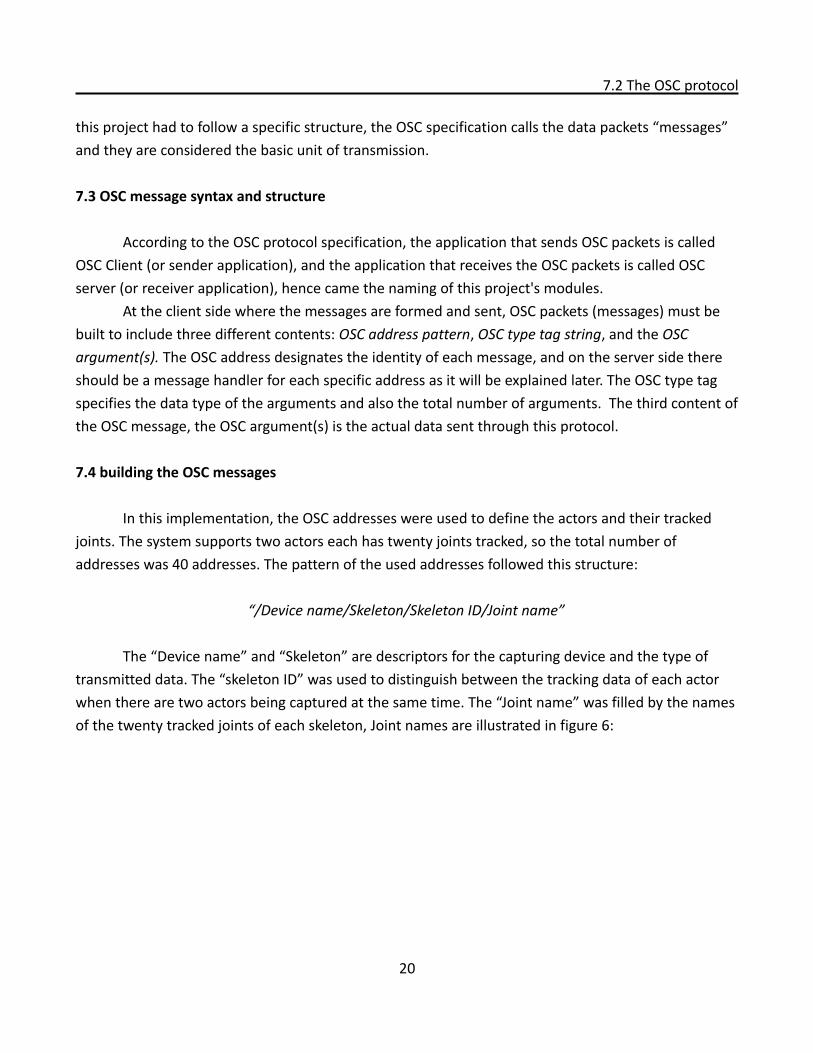
The “Device name” and “Skeleton” are descriptors for the capturing device and the type of transmitted data. The “skeleton ID” was used to distinguish between the tracking data of each actor when there are two actors being captured at the same time. The “Joint name” was filled by the names of the twenty tracked joints of each skeleton, Joint names are illustrated in figure 6:
20
7.4 building the OSC messages
Examples of OSC addresses used in this implementation would look like this:"/Kinect/skeleton/0/elbow_right”
"/Kinect/skeleton/1/head”"/Kinect/skeleton/0/hip_center”"/Kinect/skeleton/1/foot_left”
This was the first component of the OSC message: the address pattern. The second component which is the type tag was simply “,fff” in all the messages which means that this message has three arguments of the type float32 (floating-point numbers). The last component is the arguments themselves, and they were the positional data of each joint in the 3D space, in the x-axis, y-axis, and z-axis respectively.
7.5 receiving the OSC messages
The second part of the networking module was the receiver code which was written in Python as mentioned earlier, as this was the implementation language of the whole server application. This was one of the great benefits of using the OSC protocol, allowing the sender and receiver to be
21
Figure 6: Conventional joint names
7.5 receiving the OSC messages
written in two different programming languages while attaining a seamless communication. In the receiver code, an OSC server was declared and initialized. Then callback functions
(message handlers) were created for all the addresses expected to be received. Finally functions for starting the server and closing it were created. The OSC server was designed to be running on a separate thread, so starting and closing the threads was also handled in these functions.
The receiver code was tested afterwards, but at this stage message handlers had no functions allotted to them yet, so instead, message handlers were instructed to acknowledge the reception of the OSC messages coming from the client application and print it out to the console screen. The messages sent from the client application were received correctly without any compromises because of the difference in implementation languages between the sender and the receiver. The next step was to develop the server application in its entirety.
22
8. Server Module Development
8. Server Module Development
The server module is the core of the whole system. The server application allows the users to visualize the motion capture data in 3D space. It also allows them to store this data on 3D skeletons as recorded animations, which is considered the main functionality of the whole system. The users have control over the capturing process through a simple GUI. The end result of the capturing process at the server side is an automatically created 3D skeleton(s), recorded on it the motion data and ready to be used further by animators in their 3D productions. The server application also gives the animators the possibility of creating 3D characters for the sake of animation retargeting. The server application was coded in Python programming language.
8.1 The server script
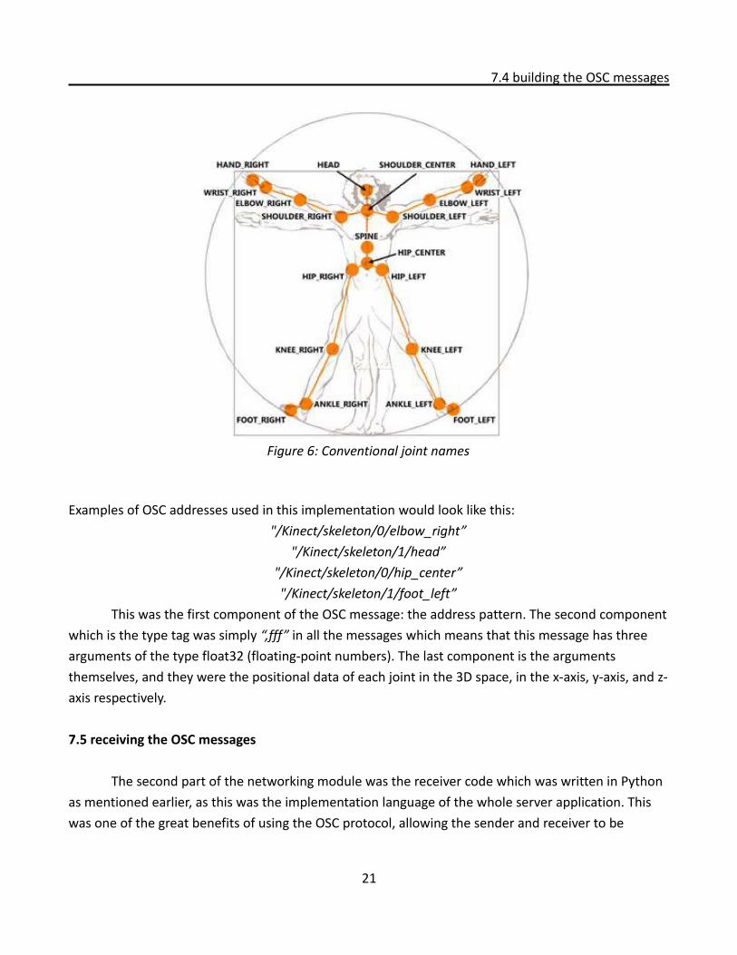
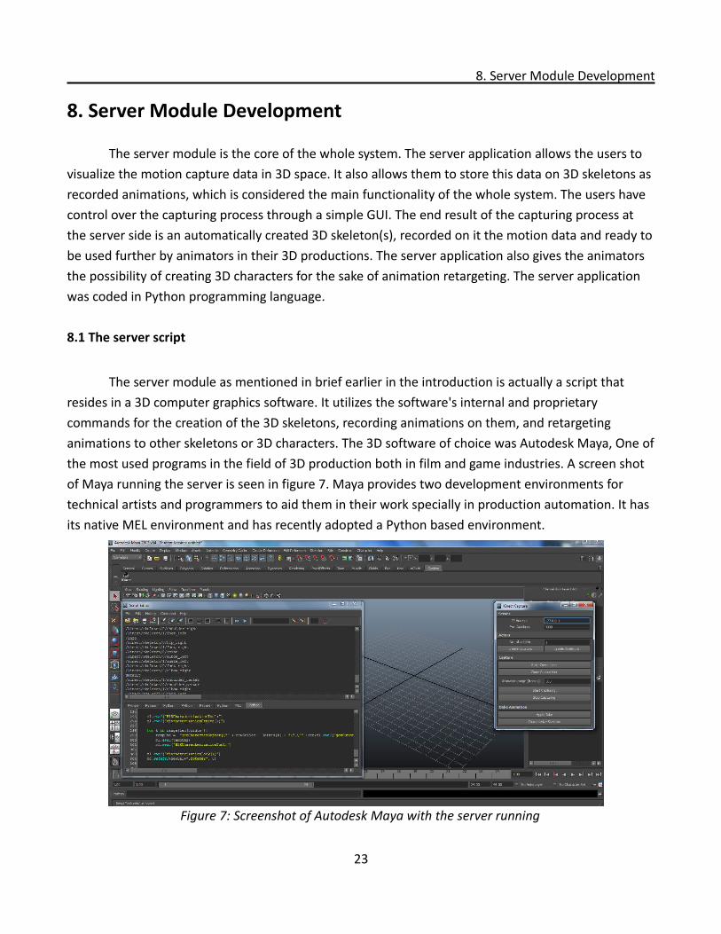
The server module as mentioned in brief earlier in the introduction is actually a script that resides in a 3D computer graphics software. It utilizes the software's internal and proprietary commands for the creation of the 3D skeletons, recording animations on them, and retargeting animations to other skeletons or 3D characters. The 3D software of choice was Autodesk Maya, One of the most used programs in the field of 3D production both in film and game industries. A screen shot of Maya running the server is seen in figure 7. Maya provides two development environments for technical artists and programmers to aid them in their work specially in production automation. It has its native MEL environment and has recently adopted a Python based environment.
23
Figure 7: Screenshot of Autodesk Maya with the server running
8.2 MEL versus Python
8.2 MEL versus Python
To choose between the two environments, a brief comparison was made to decide which environment would better suit the server application's needs. The main advantage of using the MEL environment is that MEL is the native language of Maya and it runs faster than Python in most of the cases. However, It is limited in its functionality and it was rather difficult to integrate it with the OSC receiver code. The Python environment, on the other hand, provided the needed flexibility for such integration. Additionally, Python is an object oriented language, and has a wider base of users contributing thousands of freely available classes that one could use. But the main advantage of Python over MEL is the fact that MEL is a proprietary language and can only be used inside Maya, but Python is a generic language, and many 3D authoring programs nowadays have internal Python interpreters, which made porting the server script from one program to another possible. So the decision was made to use Python as the server's implementation language.
8.3 Server application in details
To start implementing the server module, it was beneficial to divide the whole structure into distinct blocks each performing a specific task. This division helped with having a clear idea of the implementation progress, and also helped when the server's features were evaluated against the user requirements.
First there was the receiver code already developed in the networking development phase, it only needed to be integrated into the Maya python environment. This needed Maya to acknowledge the external python interpreter, so that importing external modules can be done. When this was done, the Maya python environment was able to communicate with the client application seamlessly.
Next, the core functionalities of the motion capturing system were developed in accordance with the blocks decided earlier at this stage. The first core block was to automate the 3D skeletons creation as required by the users. A procedure was made to create a skeleton with the correct joints hierarchy and using the Kinect joints naming convention. This procedure could be executed twice if there are two actors being captured simultaneously. Another procedure was developed to create a number of dummy locators (NULL objects) with the same naming convention. The reason behind creating this functionality was to extend the user's possibility of using the motion captured data beyond the normal skeletal system, for example, using the recorded animations in the simulation of particle systems. This procedure also can be executed twice to cater for two actors performing simultaneously.
The second core block was the capturing block, where the previously created skeletons are
24
8.3 Server application in details
used to visualize the streamed data (coming from the Kinect sensor through the client application) in 3D space. In this block the OSC server would be activated to receive the OSC messages, and then the OSC message arguments are extracted from each message, these arguments as mentioned earlier are the positional data in 3D space for each joint and each skeleton available. The arguments are then matched to their corresponding joints, and fed into the joint translation attributes to recreate the motion inside Maya. As the server gets new messages with new positional data this procedure keeps updating in realtime. Another task in this block was to code the procedure for the recording of the animation. This procedure is only activated when the user instructs the server to start recording. When the procedure is called, the motion data would be written and saved in an external text file. Each joint and its corresponding position attributes are recorded for each frame to be retrieved later. When there are two actors, two separate files would be written each having its corresponding data. All the procedures that are called in realtime were then packed into the message handlers call-back functions. The final two procedures coded in this block were the ones responsible for closing the connection with the client, and stopping the animation recording session.
The Third and final core block was the one responsible for applying the recorded animation data on the 3D skeletons and NULL objects. This included reading the external text files, retrieving the joint names and positional attributes for each frame, applying these attributes on the corresponding joints, and finally keyframing (setting key frames on each joint in each frame) all the attributes. This is a batch process and is not done in realtime, however the result is the exact captured motion in realtime. By executing this block, the user would get a saved copy of the recorded animation session that can be further fine-tuned and edited according to the user's preferences.
8.4 The server's GUI
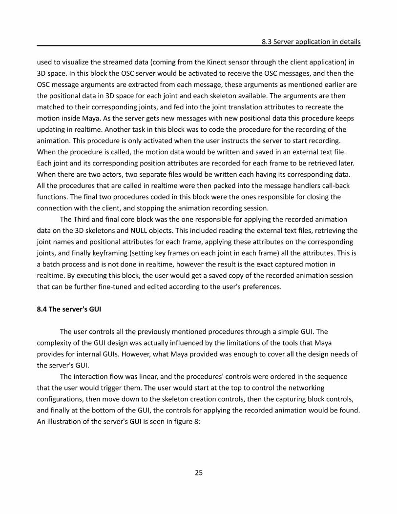
The user controls all the previously mentioned procedures through a simple GUI. The complexity of the GUI design was actually influenced by the limitations of the tools that Maya provides for internal GUIs. However, what Maya provided was enough to cover all the design needs of the server's GUI.
The interaction flow was linear, and the procedures' controls were ordered in the sequence that the user would trigger them. The user would start at the top to control the networking configurations, then move down to the skeleton creation controls, then the capturing block controls, and finally at the bottom of the GUI, the controls for applying the recorded animation would be found. An illustration of the server's GUI is seen in figure 8:
25
8.4 The server's GUI
After linking the GUI controls to their corresponding procedures, the regular testing sessions took place, mainly to ensure that all the server's functions were performing correctly. Testing the external text files for proper data saving and retrieval was crucial, and it took a significant amount of time to ensure that the data is recorded and retrieved correctly without any compromises to the data integrity. When the test results were satisfying, a broader type of testing was needed for all the modules of the system together. This testing phase is discussed in chapter 9.
8.5 Porting server code to MotionBuilder
One last activity, related to the server development phase, was to try the script code in other 3D graphics applications. Autodesk's MotionBuilder was the software chosen, mainly because it has its internal python interpreter, and also because it is one of the most widely used applications for 3D animation purposes. It was thought that the porting process would be achieved with minor changes to the script's code, however, in practice, this was proved to be wrong.
MotionBuilder's Python scripting environment wasn't really written in Python, but it was an exposed subset of the main C++ SDK written in Python syntax. So the coding paradigm is actually C++ and not Python. Additionally, many of the Python core commands have not been released yet even in
26
Figure 8: Server's GUI inside Maya
8.5 Porting server code to MotionBuilder
version 2012. This unforeseen characteristic of MotionBuilder's Python environment caused major changes to the originally written code.
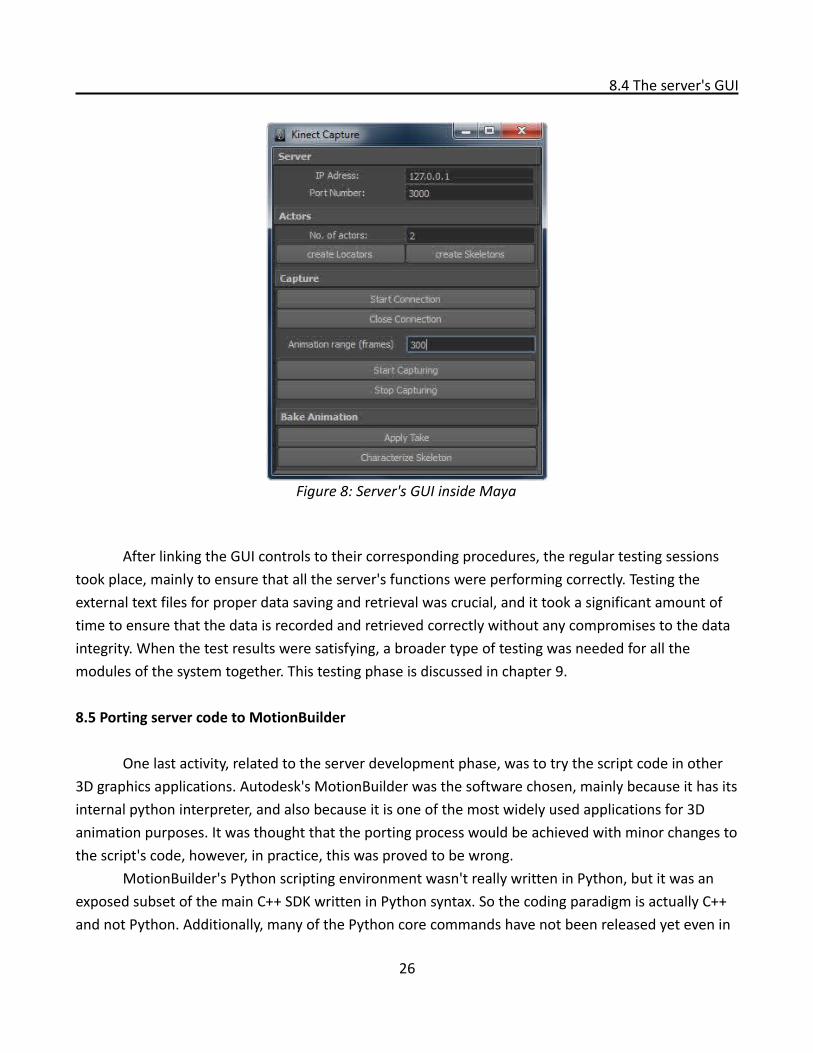
Another obstacle faced in the porting process (even after changing the code to work with the Motionbuilder environment) was that the script was working properly but not updating the viewport in realtime. Which rendered the script useless as it has to show the results in realtime. This problem was investigated, and after a significant time of researching the causes of such behavior, it was discovered that MotionBuilder's viewport works on a separate thread and the rest of the computations happen on a different thread. To solve this problem, a procedure that works on the viewport thread was created to force updating the viewport in realtime. After creating this procedure, the script finally worked as expected. This script and MotionBuilder environment can be seen in figure 9.
8.6 MotionBuilder's script limitations
The main limitation, discovered after the porting process, was that updating the viewport using the created procedure sacrificed some performance speed. It was not very noticeable, but the system couldn't work at the optimum 30 FPS. This also caused the implementation to be restricted to only one actor to avoid further performance degradation.
Another limitation was that a GUI couldn't be implemented as it would stop the viewport from updating until it is closed, so the scripts only works through the internal script editor only.
27
Figure 9: Server running inside MotionBuilder
9. System Integration Testing
9. System Integration Testing
By that time of the project's progress, each module was created and tested separately both for functionality and against the user requirements. It was the time then to have a broader scope during testing. The main aim of the “System Integration Testing” phase was to test the system in its entirety. Test scenarios were first envisioned to test all the possible cases for using the system. These scenarios included:
• Changing the default networking configurations in both the client and server, for example using a different port number.
• Testing and recording animation with only one actor.• Testing and recording animations of two actors simultaneously.• Changing the Kinect device settings on the client side and seeing the changes in the server, for
example changing the smoothing algorithm settings or the camera angle.• Testing the client's application generic settings.• Testing several placements of the Kinect device and checking how this would affect the
capturing process.• Testing extreme poses for the Kinect to capture, like fast movements, crawling poses, and full
rotations. Unfortunately, in which the system didn't perform satisfyingly.
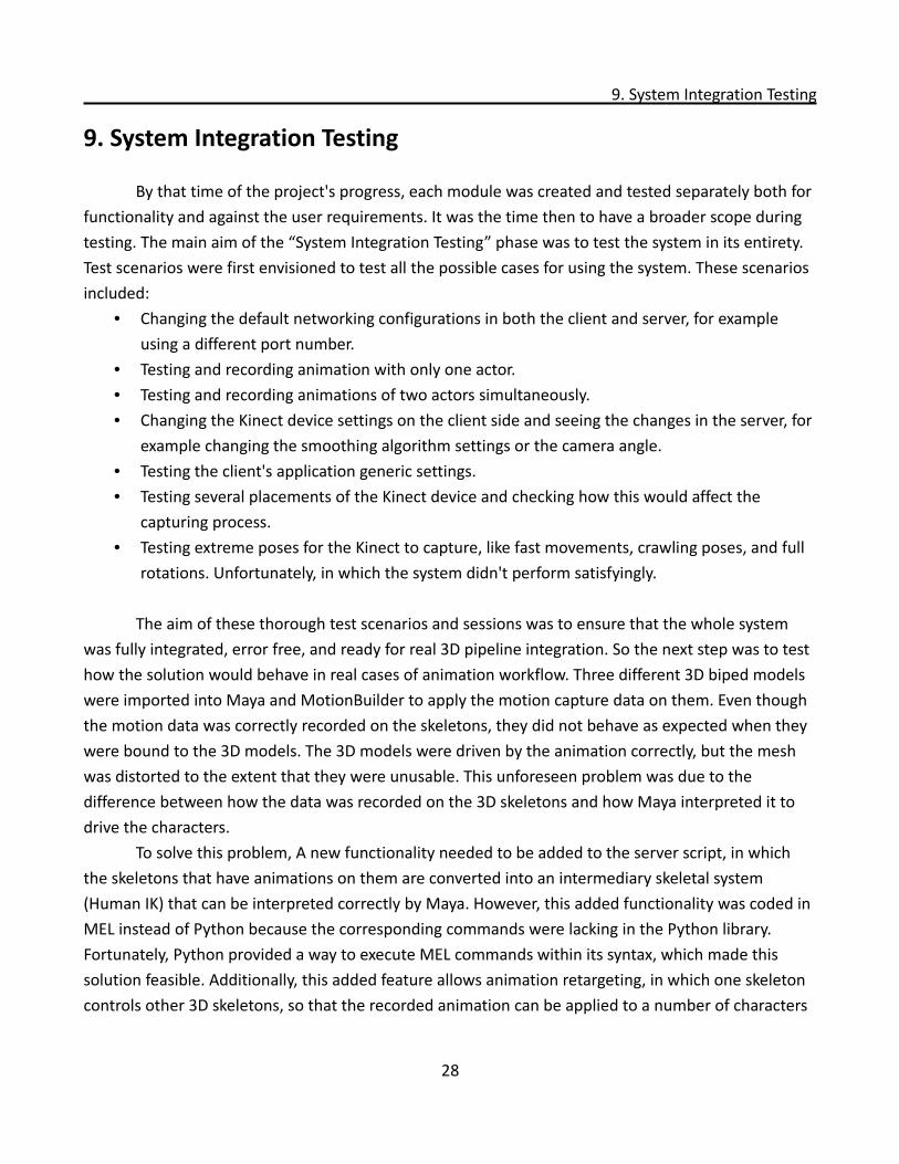
The aim of these thorough test scenarios and sessions was to ensure that the whole system was fully integrated, error free, and ready for real 3D pipeline integration. So the next step was to test how the solution would behave in real cases of animation workflow. Three different 3D biped models were imported into Maya and MotionBuilder to apply the motion capture data on them. Even though the motion data was correctly recorded on the skeletons, they did not behave as expected when they were bound to the 3D models. The 3D models were driven by the animation correctly, but the mesh was distorted to the extent that they were unusable. This unforeseen problem was due to the difference between how the data was recorded on the 3D skeletons and how Maya interpreted it to drive the characters.
To solve this problem, A new functionality needed to be added to the server script, in which the skeletons that have animations on them are converted into an intermediary skeletal system (Human IK) that can be interpreted correctly by Maya. However, this added functionality was coded in MEL instead of Python because the corresponding commands were lacking in the Python library. Fortunately, Python provided a way to execute MEL commands within its syntax, which made this solution feasible. Additionally, this added feature allows animation retargeting, in which one skeleton controls other 3D skeletons, so that the recorded animation can be applied to a number of characters
28
9. System Integration Testing
in the same scene. An illustration of a 3D model before solving the problem and after introducing the new feature can be seen in figure 10.
The new feature was added to the script environment, and then tested afterwards with the three different 3D models. It was later added to the GUI in the “Baking animation” block discussed earlier. For this feature to be applied correctly, the user needed to select a skeleton first before executing the command, so a tool tip was added to inform the user of the correct sequence of applying this command.
Finally, the whole solution was tested again to ensure that nothing went wrong while solving the aforementioned problem. As a result of these tests, it was sure at that time that the motion capturing solution was capable of being used in real life scenarios that animators usually face on a daily basis in their work.
29
Figure 10: Distorted model (left) and after correction (right)
10. Testing Usability
10. Testing Usability
Since the commencement of this project, an HCD philosophy has been adopted, to ensure the involvement of the user from the early stages of design up till the project's full development. An integral part of any HCD process is to hold usability test sessions in which representatives of the target users test the proposed solution and provide their feedback and satisfaction rate. In this project usability tests were performed using two approaches, video testing, and Evaluation walkthroughs.
10.1 Video tests
In this approach, a video of the system being used was recorded, and distributed among professional animators accompanied with some questions to generate a fruitful feedback. This approach is actually an informal and unorthodox way of testing usability, but the aim of this kind of test was to reach a decent number of target users, and hopefully get some general feedback. The questions asked were:
• would you use this solution in your work?• How satisfactory is the solution itself?• How satisfactory is the quality of the end result that the solution produces?• What can be improved in this implementation?
The video was seen by more than 250 viewers in 4 weeks [42]. However, only 20+ viewers have given their feedback either on social network websites or personally. All of those viewers agreed that they would use the solution when made available, however, there was a concern about the quality of the output, many mentioned that this solution can be used for animating the secondary characters but not the main ones. Several viewers were interested in having a solution for facial and finger tracking, or higher number of joints tracked per character. On the other hand, the solution workflow and interface gained the satisfaction of all viewers.
It is worth mentioning that several developers and researchers contacted the researcher for a copy of the source code. This wish will be granted to them when the project is finalized. The whole solution will be provided with the source code for anyone interested in developing the project furthermore.
The limitations of the solution were discussed with some of the viewers as well as how this project can be improved in the future. Some of the demands were unrealistic because of the project's scope and the restrictions imposed by the framework used. However, some suggestions were adopted and implemented, and some other demanded features may be developed in the future releases of this system.
30
10.2 Evaluation walkthrough
10.2 Evaluation walkthrough
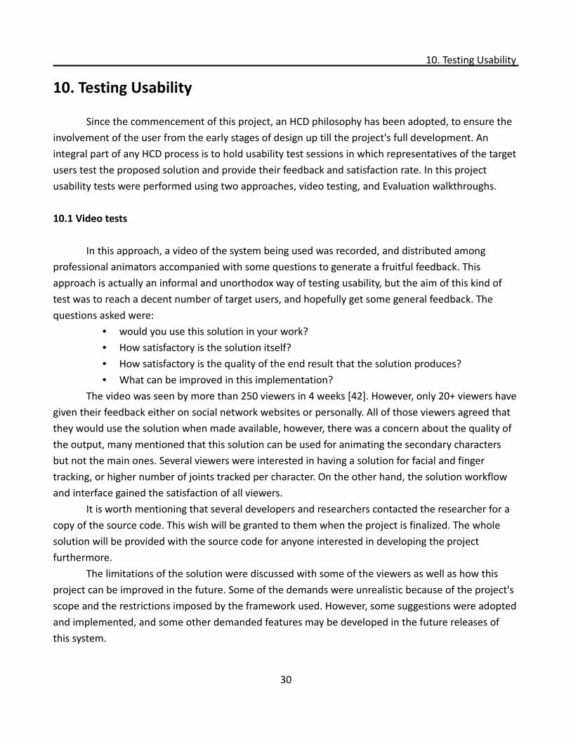
Formal testing methods have also taken place in this project. Several 3D animators participated in “evaluation walkthrough” test sessions. In these sessions, the test users were introduced to the system, a guided walkthrough was given to them first, and then they were allowed to test the system on their own. During these session users were observed and the observations were noted down. The sessions were also recorded using a realtime screen capture software(see figure 11). These videos were used later for further analysis and comparisons. The users were asked to describe what they were doing, and if they were able or unable to achieve the correct output at each stage. After the walkthroughs, concluding discussions usually took place to get further remarks and feedback.
These sessions resulted in more indepth feedback and conclusions. The findings can be summarized in the following points:
• The system was tested in different lighting conditions, yet the results were not affected by the ambient light in the room, since the tracking is based on IR lighting projected from the sensor.
• The system would fail if the client started before the initiation of the server. Streaming data
31
Figure 11: Screenshots from the recording of a test session
10.2 Evaluation walkthrough
needs to be received by the message handlers in the server, otherwise Maya would crash. So the correct sequence concluded was to start the server in Maya or MotionBuilder first then start the client afterwards.
• Two testers mentioned that the GUI is a bit complicated to comprehend for the general user, but on the other hand, they also said that they expected a complicated GUI as it is the case with most of the 3D animation applications and their plug-ins.
• All testers tried extreme and fast movements and poses, and the results were not satisfying to some extent. They agreed that such solution isn't preferable to be used to animate primary characters, but would be very usable with secondary characters as they don't need the same precision or high-resolution quality.
• There was a general concern about the head and chest joints rotations. They were captured correctly on the skeleton, but in the retargeting step they lost some details.
• One user tried a full 360 degrees rotation, which was not captured at all by the system.• The same user tried to create a walk cycle animation out of the captured data, and he found
the results very satisfying.• The solution can keep running without any degradation in the performance for enough time
to capture several takes. The longest take recorded was slightly over a minute long.• The concluding remarks usually revolved around the restriction and intent of use. The
restrictions discussed were about the system being only capable of tracking human characters only, and the limited number of joints implemented, and the precision problems. Regarding the system's usage, there was an agreement that it can benefit freelance animators and small studios. All the testers commented on how this solution can make life easier, and their workflow much faster.
32
11. Conclusions
11. Conclusions
This thesis started with definite questions that needed to be answered. And through the progress of the work the answers started to evolve and mature. This chapter presents the answers to the research questions, which were:
• How one can build a simple and affordable motion capture system?◦ what are the different approaches to create an optical motion capture system
using NUI based devices? And what is the difference between these approaches?
◦ How can a Kinect based MoCap be built in the most straightforward way?
11.1 Answer to research questions
This research project proved that it's feasible to build a simple and affordable MoCap system. The early chapters of this dissertation discussed the different approaches toward creating such system. Different NUI devices were investigated and the Kinect sensor was chosen as the most suitable device to build the system on. Among the researched devices: SoftKinetic DepthSense, Asus Xtion PRO, and Microsoft Kinect. The Kinect was favored over the other devices because of its wide spread and availability, and because of its built-in skeletal tracking framework.
Additionally, possible development frameworks and SDKs were investigated and compared, specifically, the OpenNI framework and the Kinect SDK for Windows. It has been concluded that the Kinect SDK is easier and more straightforward to use, and also that it provides better motion capturing capabilities and features. Nonetheless, OpenNI is a strong candidate and would be a better candidate in other contexts of use.
The latter chapters of this dissertation discussed the practicality and the process of building a Kinect based MoCap in the most straightforward way. The Kinect SDK provided the foundation of the work. With the aid of the Cinder library, a simple client application was built using the C++ programming language, and the server was implemented inside Autodesk Maya and Autodesk MotionBuilder using the Python programming language. The solution provided intuitive ways of interacting with the system through the use of GUI.
It is believed that this pursued track of design and implementation succeeded in building a simple and affordable MoCap using the simplest and the most straightforward approaches.
33
12. Discussion
12. Discussion
The aim of this thesis was to investigate the different approaches to build a simple and affordable MoCap system, then design and build one solution in the most straightforward way. This was achieved by investigating the previous endeavors and related research material. This was followed by the actual development of the system. An integral part of this project was to keep the target user involved in all the decisions made, this was achieved by the early adoption of an iterative HCD process that helped to design and build a usable solution.
12.1 Evaluation
By analyzing the implementation output and the usability tests results, it can be concluded that the implemented system can produce satisfactory results in some specific contexts. The results would be satisfactory to animate secondary characters in a movie or a game. Also, this solution could be used with primary characters if the primary character's movements are not very extreme, and if no fingers' tracking is needed. Otherwise, the quality of the output would fail to gain satisfaction or would need further fine tuning and editing.
With regard to the system's performance, it can be said with certainty that the solution is very stable and bug-free, but it requires a computer with decent memory and processing speed. The system expects a specific and ordered sequence of interactions for it to produce the correct results, otherwise, it would fail to work. The researcher admits that more error and exception handlers may be needed for giving a more intelligible feedback to the user. Generally speaking, the system runs within the optimum frame rate of 25-30 FPS. The frame rate slightly drops when the system is tracking two users simultaneously, but still within the 25-30 FPS range.
A drawback in this implementation is the large number of libraries that the system depends on, which resulted in a complicated dependency pattern. On the client side, There are the Kinect SDK, the Cinder library, and the Kinect wrapper. On the server side, one needs both internal and external python interpreters, the OSC protocol and its implementation, and the simple OSC helper library. Replicating this complex environment is needed for the system to work on other workstations, or to be further developed by interested researchers.
12.2 Comparison with similar projects
As it has been mentioned earlier, similar projects were scarce and were lacking either documentation or source code, or even both. However, this project can be considered a more
34
12.2 Comparison with similar projects
methodological extension to previous endeavors. Although it had the same aim like other projects, which is building a simple and affordable Mocap system, it followed a more scientific approach towards achieving this aim. Additionally, this project adopted a more holistic view in solving the problem at hand, in addition to its human-centered approach.
The closest application that can be compared to this implementation is the ”Brekel Kinect”, they both stream motion data from the Kinect sensor to 3D animation programs. They both provide skeleton and character creation tools. And of course, they both provide a recording functionality. The main difference is that Brekel Kinect only works with MotionBuilder, while this implementation works with both Maya and Motionbuilder. Also, the two projects use different NI frameworks, and different streaming protocols. Due to the difference in frameworks, it can be said that the tracking quality in Brekel Kinect is a little less than the quality of the tracking in this implementation. However, if we compare only the MotionBuilder implementation and Brekel Kinect, it is evident that Brekel's implementation is far more robust than the MotionBuilder script developed in this project. It can be said that the two projects are rather complementary as they serve different bases of users. At the same time, for Motionbuilder users, it is admitted that Brekel Kinect is superior due to its robustness.
12.3 Future work
This project used the initial version of the Kinect SDK, and during the course of this project, Microsoft published a newer version stating that it provides enhancements to the skeletal tracking algorithm. It is believed that testing the new SDK should be the next step, in order to take advantage of the enhancements. Equally important and to get more user satisfaction, the calculation of joints rotation will be added to system.
Another possible future enhancement is converting the server script into a Dynamic-Link Library file (DLL), which can enhance the memory usage and provides an easier way to distribute the application.
For the MotionBuilder implementation, it seems like using Python is not very effective, if this part is further developed, then the original C++ SDK will be used instead of the exposed Python SDK.
It will be also interesting to try to implement a facial tracking and motion capturing feature. However, since this uses a totally different technique and other sets of libraries, it may be more realistic and efficient to implement it as a separate solution. Most probably, this feature will need the use of point cloud data and mesh reconstruction libraries, so it will be another journey of investigation, exploration, and learning!
35
References
References
[1] Oates, B. (2011). Researching information systems and computing. (pp. 108-124). London: SAGE publications
[2] Jokela, T., Iivari, N., Matero, J., & Karukka, M. (2003). The Standard of User-Centered Design and the Standard Definition of Usability : Analyzing ISO 13407 against ISO. (S. D. J. Barbosa & C. Gonzalez, Eds.)Design, 46, 53-60. ACM. Retrieved from http://portal.acm.org/citation.cfm?doid=944519.944525
[3] Ash Consulting. (n.d.). ISO 13407: Human centred design process for interactive systems. Retrieved February 21, 2012, from http://www.ash-consulting.com/ISO13407.pdf
[4] Kroll, P. (2004, April 16). Transitioning from waterfall to iterative development. Retrieved February 21, 2012, from http://www.ibm.com/developerworks/rational/library/4243.html
[5] Maguire, M. (2001). Methods to support human-centred design. International Journal of Human-Computer Studies, 55(4), 587 - 634. doi: 10.1006/ijhc.2001.0503
[6] Rowley , D., & Rhoades, D. (1992). The cognitive jogthrough: a fast-paced user interface evaluation procedure. In Proceedings of the SIGCHI conference on human factors in computing systems (chi '92), New York, NY, USA. doi: 10.1145/142750.142869
[7] Interactive Systems & User Experience Lab. (n.d.). Kinect sdk - unity 3d interface plugin. Retrieved February 21, 2012, from http://www.eecs.ucf.edu/isuelab/unity.php
[8] Onethought99. (Designer). (2011). Kinect / OpenNi to UDK. [Web Video]. Retrieved February 21, 2012, from http://www.youtube.com/watch?v=JEDRsA0WsJg
[9] Walsh, J. (Designer). (2011). Kinect plugin for daz studio. [Web Video]. Retrieved February 21, 2012, from http://vimeo.com/20909755
[10] Brekelmans, J. (2011). Brekel Kinect. [Web log message]. Retrieved February 21, 2012, from http://www.brekel.com/?page_id=155
36
References
[11] PrimeSense. (n.d.). Primesense Natural Interaction. Retrieved February 21, 2012, from http://www.primesense.com/nite
[12] Radius9. (2011). Radius9 motion capture utility. Retrieved February 21, 2012, from http://www.radius9.com/downloads_mocap.html
[13] User guide for single kinect sensor configuration. In (2011). IPiSoft. Retrieved February 21, 2012, from http://www.ipisoft.com/en/wiki/index.php?title=User_Guide_for_Single_Kinect_Sensor_Configuration
[14] Organic Motion. (n.d.). Technology. Retrieved February 21, 2012, from http://organicmotion.com/solutions/technology
[15] Organic Motion. (Designer). (2011). Organic motion and kinect integration for real-time markerless motion capture - r&d preview. [Web Video]. Retrieved February 21, 2012, from http://www.youtube.com/watch?v=T9Mg7qIZr1I
[16] Kühn, T. (2011). The kinect sensor platform. Advances in Media Technology, 2, 1-4. Retrieved February 21, 2012, from http://www.lmt.ei.tum.de/courses/hsmt/proceedings/pdf/ss2011/01Kinect.pdf
[17] Lacko, D., Schrooyen, F., & Beyers, R. (2011). Motion capture and guidance using open source hardware.PAPERS OF THE E-LAB MASTER’S THESES 2010–2011, 1-7. Retrieved February 21, 2012, from http://www.artesis.be/iw/elab/MAP/2010-2011/AMBIT-Lacko.pdf
[18] Oikonomidis, I., Kyriazis, N., & Argyros, A. (2011, August). Efficient model-based 3d tracking of hand articulations using kinect. In Proceedings of the 22nd British machine vision conference, UK. Retrieved February 21, 2012, from http://www.ics.forth.gr/~argyros/mypapers/2011_09_bmvc_kinect_hand_tracking.pdf
[19] Shotton J., Fitzgibbon A., Cook M., Sharp T., Finocchio M., Moore R., Kipman A., & Blake A. (2011, June). Real-time human pose recognition in parts from single depth images. In Proceedings of CVPR2011, Colorado Springs, USA . Retrieved February 21, 2012, from http://research.microsoft.com/pubs/145347/BodyPartRecognition.pdf
37
References
[20] Kar, A. (2011). Skeletal tracking using microsoft kinect. Retrieved February 21, 2012, from http://home.iitk.ac.in/~akar/cs397/Skeletal Tracking Using Microsoft Kinect.pdf
[21] Sung, J., Ponce , C., Selman, B., & Saxena, A. (2011). Human activity detection from RGBD images. CoRR,abs/1107.0169, Retrieved February 21, 2012, from http://arxiv.org/abs/1107.0169
[22] Dutta, T. (2011). Evaluation of the kinect™ sensor for 3-d kinematic measurement in the workplace. Applied Ergonomics. doi: 10.1016/j.apergo.2011.09.011
[23] Villaroman, N., Rowe, D., & Swan, B. (2011). Teaching natural user interaction using OpenNI and the Microsoft Kinect sensor. In Proceedings of the 2011 conference on Information technology education (SIGITE '11). ACM, New York, NY, USA, 227-232. doi: 10.1145/2047594.2047654
[24] Hsu, H. (2011). The potential of kinect in education. International Journal of Information and Education Technology, 1(5), 365-370. Retrieved February 21, 2012, from http://www.ijiet.org/papers/59-R025.pdf
[25] Gimeno, J., Coma, I., & Fernández, M. (2011). Augmented mirror: Interactive augmented reality system based on kinect. In P. Campos, N. Graham, J. Jorge, N. Nunes & P. Palanque (Eds.), Human-Computer Interaction – INTERACT 2011 (pp. 483-486). doi:10.1007/978-3-642-23768-3_63
[26] Bleiweiss, A., Eshar, D., Kutliroff, G., Lerner, A., Oshrat, Y., & Yanai, Y. (2010). Enhanced interactive gaming by blending full-body tracking and gesture animation. In Proceedings of ACM SIGGRAPH ASIA 2010 Sketches (SA '10). ACM, New York, NY, USA, , Article 34 , 2 pages. doi:10.1145/1899950.1899984
[27] Schönauer, C., & Kaufmann, H. (2011). Wide Area Motion Tracking Using Consumer Hardware.In Proceedings of Workshop on Whole Body Interaction in Games and Entertainment, Advances in Computer Entertainment Technology (ACE 2011), Lisbon, Portugal. Retrieved February 21, 2012, from http://lister.cms.livjm.ac.uk/homepage/staff/cmsdengl/WBI2011/documents2011/Wide_Area_Motion_Tracking-P5.pdf
[28] Blake , J. (2010, November 15). Openkinect. Retrieved February 21, 2012, from http://openkinect.org/wiki/Main_Page
38
References
[29] OpenNI. (2010, November). About the OpenNI organization. Retrieved February 21, 2012, from http://www.openni.org/About.aspx
[30] OpenNI. (n.d.). Programmer Guide. Retrieved February 21, 2012, from http://openni.org/Documentation/ProgrammerGuide.html
[31] Microsoft. (2011). Microsoft Kinect SDK for developers. Retrieved January 15, 2012, from http://www.kinectforwindows.org/resources/faq.aspx
[32] Microsoft. (2011, July 22). Programming Guide. Retrieved January 15, 2012, from http://kinectforwindows.org/documents/ProgrammingGuide_KinectSDK.pdf
[33] Hinchman, W. (2011, June 20). Kinect for Windows SDK beta vs. OpenNI. [Web log message]. Retrieved February 21, 2012, from http://labs.vectorform.com/2011/06/windows-kinect-sdk-vs-openni-2/
[34] Burnett, D. (2011, June 18). Kinect- Caught between Community & MSFT support.[Web log message]. Retrieved February 21, 2012, from http://www.uxmagic.com/blog/post/2011/06/18/Kinect-Caught-between-Community-MSFT-support.aspx
[35] Brekelmans, J. (2011). Microsoft Kinect SDK vs PrimeSense OpenNI. [Web log message]. Retrieved February 21, 2012, from http://www.brekel.com/?page_id=671
[36] Schebella, M. (2011, October 3). 2realkinectwrapper. Retrieved February 21, 2012, from http://www.cadet.at/2011/10/03/2realkinectwrapper/
[37] Schieberl, S. (2011, July 22). Kinect SDK Block for Cinder. [Web log message]. Retrieved February 21, 2012, from http://bantherewind.com/kinect-sdk-block-for-cinder
[38] The Barbarian Group. (n.d.). The library for professional-quality creative coding in C++. Retrieved February 21, 2012, from http://libcinder.org/
[39] CNMAT. (n.d.). Open sound control. Retrieved February 21, 2012, from http://opensoundcontrol.org/
39

References
[40] CNMAT. (n.d.). The center for new music and audio technologies. Retrieved February 21, 2012, from http://cnmat.berkeley.edu/
[41] CNMAT. (n.d.). Introduction to OSC. Retrieved February 21, 2012, from http://opensoundcontrol.org/introduction-osc
[42] Fahim, G. (Designer). (2011). Mocap Test: Kinect + Maya Using Kinect SDK and Python. [Web Video]. Retrieved February 21, 2012, from http://youtu.be/EK-niqray10
40
Appendix: Technical Documentation
Appendix: Technical Documentation
Purpose
This document covers the technical aspects of the solution in more details. It aims at making the whole system more comprehensible and useful to both the system users and interested developers. It covers the system's software and hardware requirements, it comprehensively describes the system's technical components, and finally it provides a visual guide for using the system and some useful links to video demos and the source code.
System Overview
• The proposed system is a markerless motion capturing solution that uses the Kinect sensor as an input device. It does not require the actors to wear sensor-mounted suits thus allows them more freedom when performing their actions.
• The output of the capturing process is a 3D skeletal system composed of twenty joints, each joint represents a body part of the performing actor. The original motion is captured, digitized, and saved on the joints as key-framed animation.
• The system is composed of one standalone application: the client application and one plug-in: the server application. The client and server applications are connected through a networking module. However, the system works both locally and through a Local Area Network (LAN).
• The system supports the recording of the motion of two actors simultaneously. In addition to the actor(s), the system requires a user who is familiar with 3D character animation workflow inside Autodesk Maya or Autodesk MotionBuilder.
• The user controls both the client and server applications using a Graphical User Interface (GUI).
System Requirements
1. Hardware requirements• 32-bit (x86) or 64-bit (x64) processor • Dual-core 2.66 GHz or faster processor• Dedicated USB 2.0 bus• 2 GB RAM• A Kinect for Xbox 360 peripheral (with special USB/power cabling)• An Ethernet card
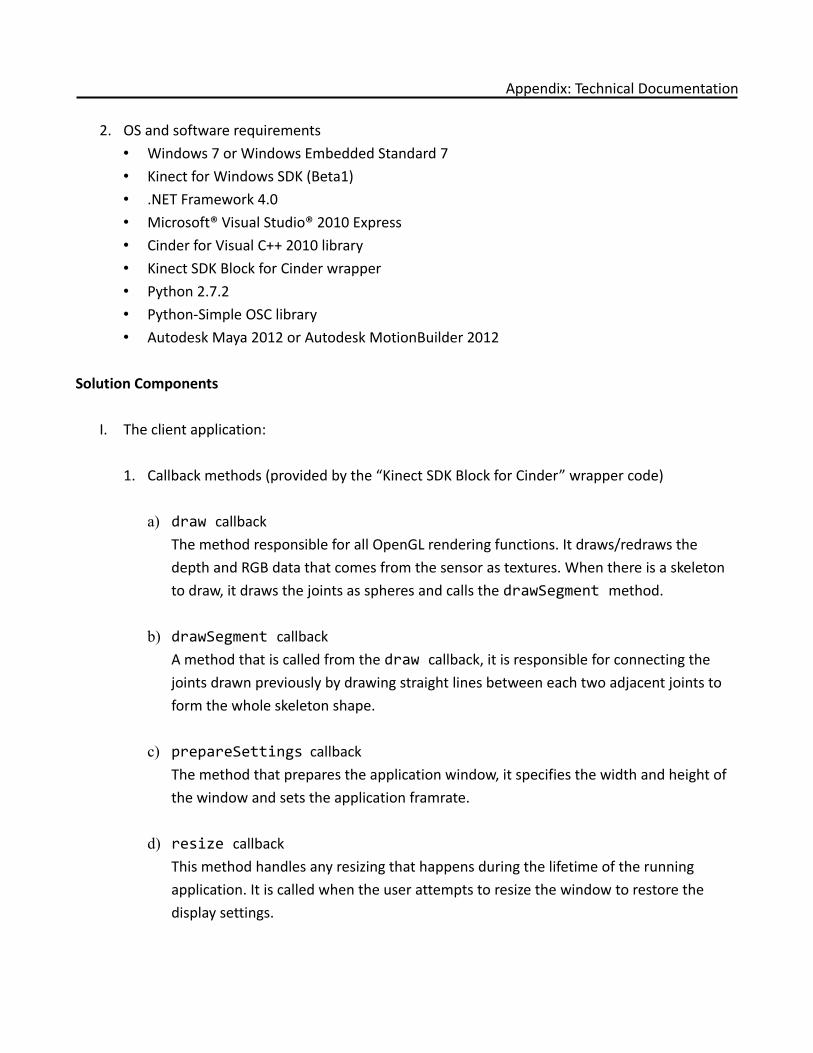
Appendix: Technical Documentation
2. OS and software requirements• Windows 7 or Windows Embedded Standard 7• Kinect for Windows SDK (Beta1)• .NET Framework 4.0• Microsoft® Visual Studio® 2010 Express• Cinder for Visual C++ 2010 library• Kinect SDK Block for Cinder wrapper• Python 2.7.2• Python-Simple OSC library • Autodesk Maya 2012 or Autodesk MotionBuilder 2012
Solution Components
I. The client application:
1. Callback methods (provided by the “Kinect SDK Block for Cinder” wrapper code)
a) draw callbackThe method responsible for all OpenGL rendering functions. It draws/redraws the depth and RGB data that comes from the sensor as textures. When there is a skeleton to draw, it draws the joints as spheres and calls the drawSegment method.
b) drawSegment callbackA method that is called from the draw callback, it is responsible for connecting the joints drawn previously by drawing straight lines between each two adjacent joints to form the whole skeleton shape.
c) prepareSettings callbackThe method that prepares the application window, it specifies the width and height of the window and sets the application framrate.
d) resize callbackThis method handles any resizing that happens during the lifetime of the running application. It is called when the user attempts to resize the window to restore the display settings.
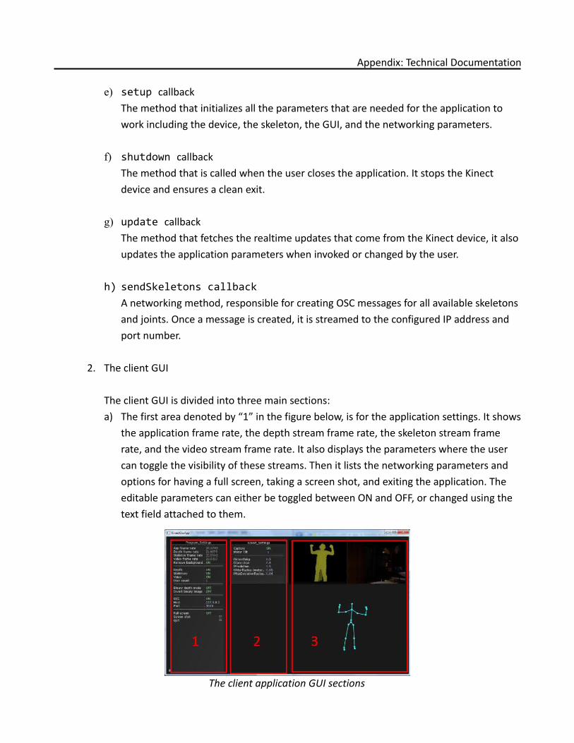
Appendix: Technical Documentation
e) setup callbackThe method that initializes all the parameters that are needed for the application to work including the device, the skeleton, the GUI, and the networking parameters.
f) shutdown callbackThe method that is called when the user closes the application. It stops the Kinect device and ensures a clean exit.
g) update callbackThe method that fetches the realtime updates that come from the Kinect device, it also updates the application parameters when invoked or changed by the user.
h) sendSkeletons callbackA networking method, responsible for creating OSC messages for all available skeletons and joints. Once a message is created, it is streamed to the configured IP address and port number.
2. The client GUI
The client GUI is divided into three main sections:a) The first area denoted by “1” in the figure below, is for the application settings. It shows
the application frame rate, the depth stream frame rate, the skeleton stream frame rate, and the video stream frame rate. It also displays the parameters where the user can toggle the visibility of these streams. Then it lists the networking parameters and options for having a full screen, taking a screen shot, and exiting the application. The editable parameters can either be toggled between ON and OFF, or changed using the text field attached to them.
The client application GUI sections

Appendix: Technical Documentation
b) The second area denoted by “2” in the figure above, is for the display of the device parameters and settings. The first parameter is a toggle switch for turning capturing ON or OFF. The second parameter is a control for the tilt motor, it is an integer field that accepts numbers between -27 and +27, which is the range of the motor's tilt angle. This area also gives the user the access to the smoothing and prediction algorithms provided by the framework. The parameters include: smoothing, correction, and prediction coefficients.
c) The third area denoted by “3” in the figure above, is dedicated for the display of the RGB-D streams and the skeleton stream.
II. The server application:
1. Callback methods
a) changeIpAndPort callbackThe method that updates the networking IP address and port number when triggered by the user. It is only accessible before a connection is created.
b) changePlayBack callbackThe method that changes the timeline length according to the user's preferences. This method is overridden by an automatically called method that uses the length of the captured animation as an input.
c) LocCreate callbackThe method that automates the creation of NULL objects (Locators). Two sets of locators can be created, one for each actor, when there are two actors performing simultaneously.
d) SkCreate callbackThe method that automates the creation of 3D skeletons (joints). Two skeletons can be created, one for each actor, when there are two actors performing simultaneously.
e) jointHandling callbackThe OSC message handler method, it changes the attributes of the created locators and skeletons and update their position in 3D space in realtime in accordance with the streamed data coming from the Kinect sensor.
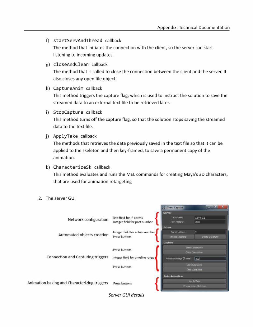
Appendix: Technical Documentation
f) startServAndThread callbackThe method that initiates the connection with the client, so the server can start listening to incoming updates.
g) closeAndClean callbackThe method that is called to close the connection between the client and the server. It also closes any open file object.
h) CaptureAnim callbackThis method triggers the capture flag, which is used to instruct the solution to save the streamed data to an external text file to be retrieved later.
i) StopCapture callbackThis method turns off the capture flag, so that the solution stops saving the streamed data to the text file.
j) ApplyTake callbackThe methods that retrieves the data previously saved in the text file so that it can be applied to the skeleton and then key-framed, to save a permanent copy of the animation.
k) CharacterizeSk callbackThis method evaluates and runs the MEL commands for creating Maya's 3D characters, that are used for animation retargeting
2. The server GUI
Server GUI details
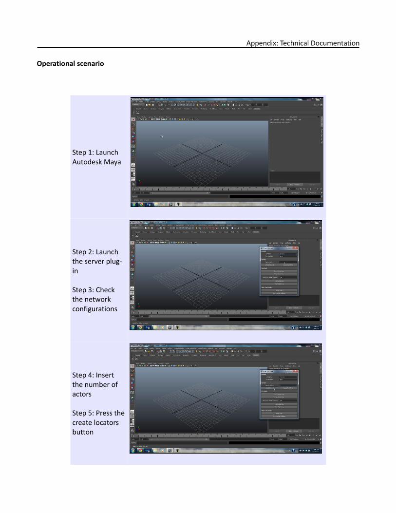
Appendix: Technical Documentation
Operational scenario
Step 1: Launch Autodesk Maya
Step 2: Launch the server plug-in
Step 3: Check the network configurations
Step 4: Insert the number of actors
Step 5: Press the create locators button
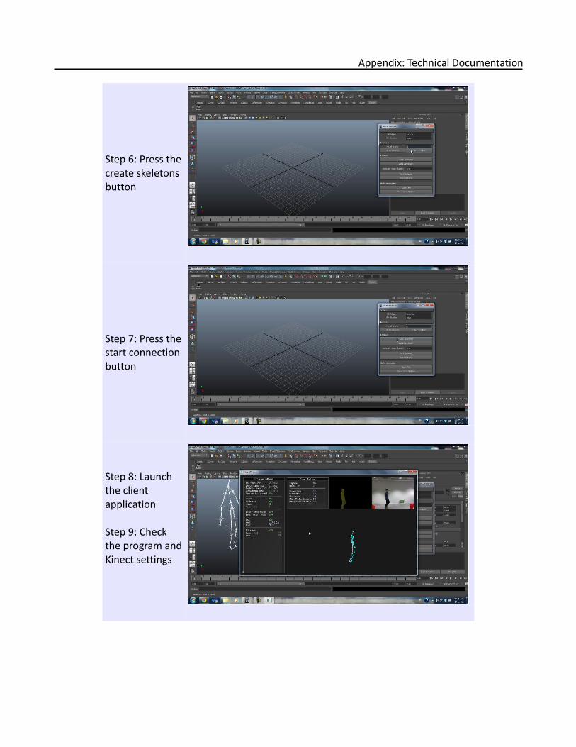
Appendix: Technical Documentation
Step 6: Press the create skeletons button
Step 7: Press the start connection button
Step 8: Launch the client application
Step 9: Check the program and Kinect settings
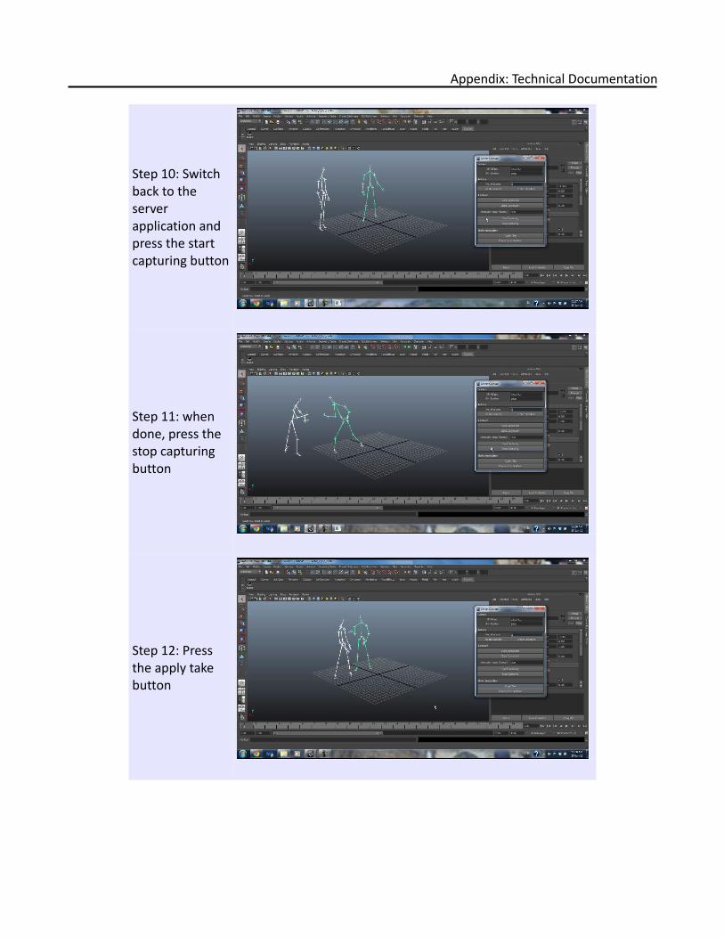
Appendix: Technical Documentation
Step 10: Switch back to the server application and press the start capturing button
Step 11: when done, press the stop capturing button
Step 12: Press the apply take button
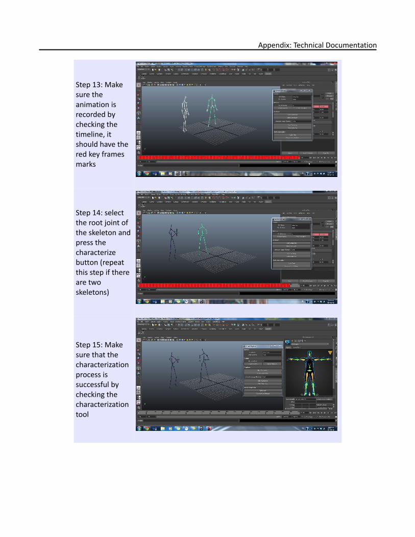
Appendix: Technical Documentation
Step 13: Make sure the animation is recorded by checking the timeline, it should have the red key frames marks
Step 14: select the root joint of the skeleton and press the characterize button (repeat this step if there are two skeletons)
Step 15: Make sure that the characterization process is successful by checking the characterization tool
Appendix: Technical Documentation
Video demos and source code links
videos: http://youtu.be/EK-niqray10http://youtu.be/LyaZFViItFIhttp://youtu.be/ZcGmU-gXuoc
source code: http://dl.dropbox.com/u/3077083/KinectOscApp.cpp http://dl.dropbox.com/u/3077083/Final_R3.py