a method of high-quality transition fault atpg for … 3, 2007 a method of high-quality transition...
TRANSCRIPT
A Method of High-quality Transition Fault ATPG for Scan Circuits
Author: Zhe WangAdvisor: Dipl.-Inf. Stefan Holst
July 3rd, 2007
(Haupt-)Seminar: Algorithms for Design-Automation - Mastering Nanoelectronic SystemsTopic 10: Transition Fault Test for Scan Circuits
July 3, 2007 A Method of High-quality Transition Fault ATPG for Scan Circuits 2
Outline
• Introduction◦ Motivation◦ Path delay, fault size and test timing◦ What is transition fault◦ How to test transition fault
• Preliminaries• Proposed ATPG algorithm• Result and discussion• Summary
July 3, 2007 A Method of High-quality Transition Fault ATPG for Scan Circuits 3
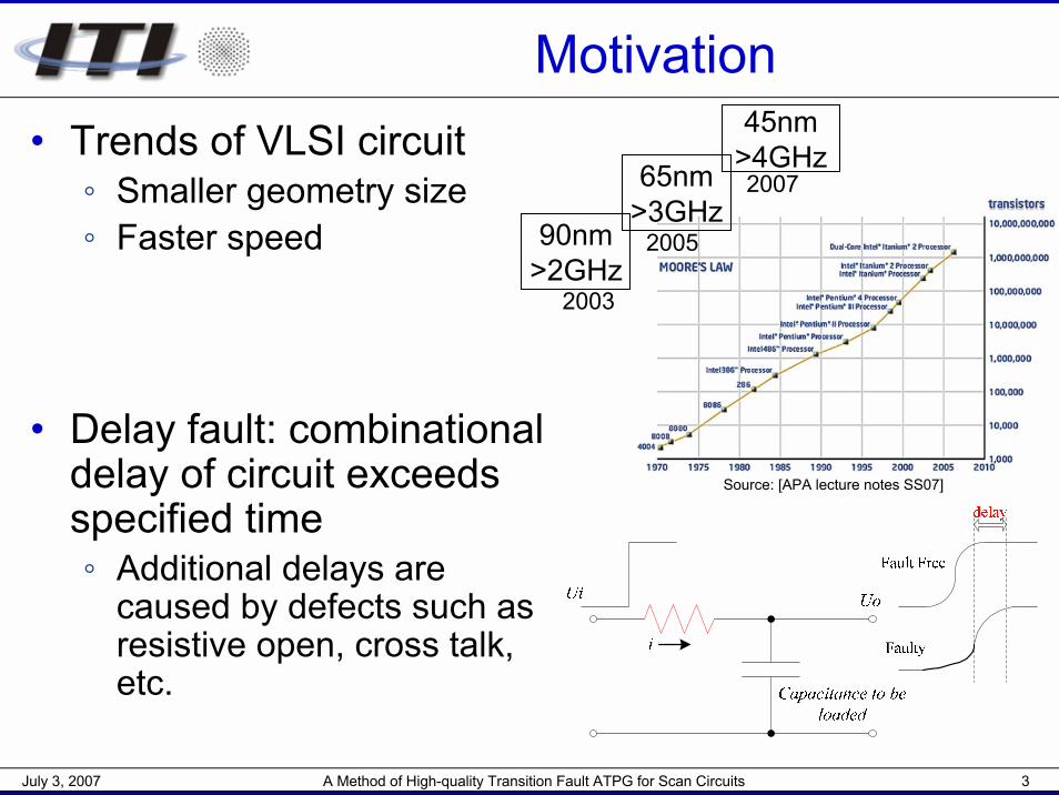
Motivation• Trends of VLSI circuit
◦ Smaller geometry size◦ Faster speed
• Delay fault: combinational delay of circuit exceeds specified time◦ Additional delays are
caused by defects such as resistive open, cross talk, etc.
90nm>2GHz
65nm>3GHz
45nm>4GHz
2003
2005
2007
Source: [APA lecture notes SS07]
July 3, 2007 A Method of High-quality Transition Fault ATPG for Scan Circuits 4
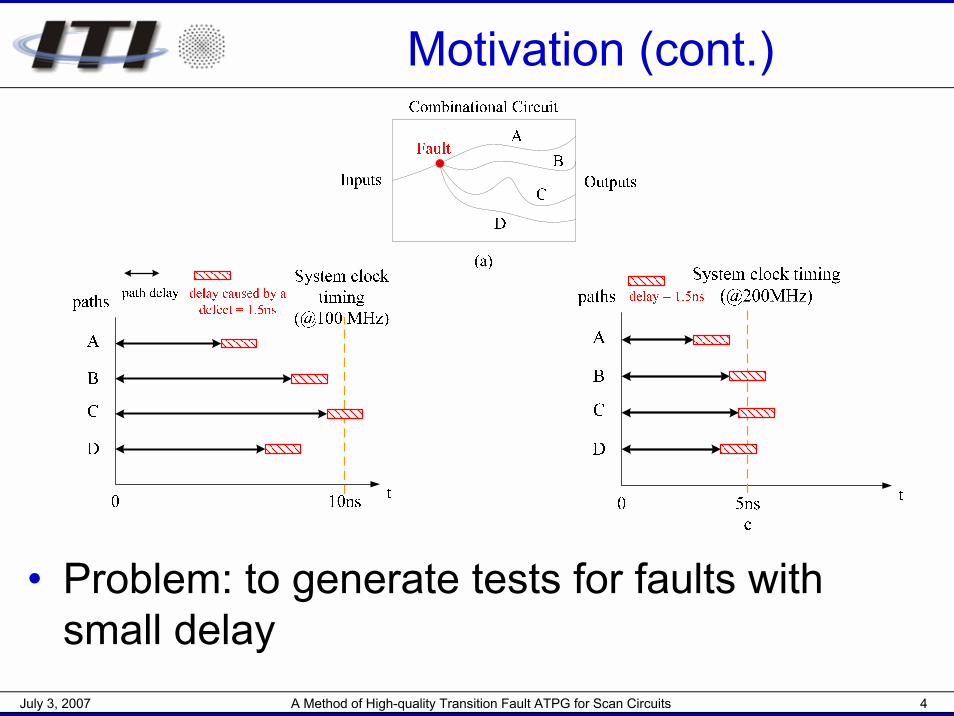
Motivation (cont.)
• Problem: to generate tests for faults with small delay
July 3, 2007 A Method of High-quality Transition Fault ATPG for Scan Circuits 5
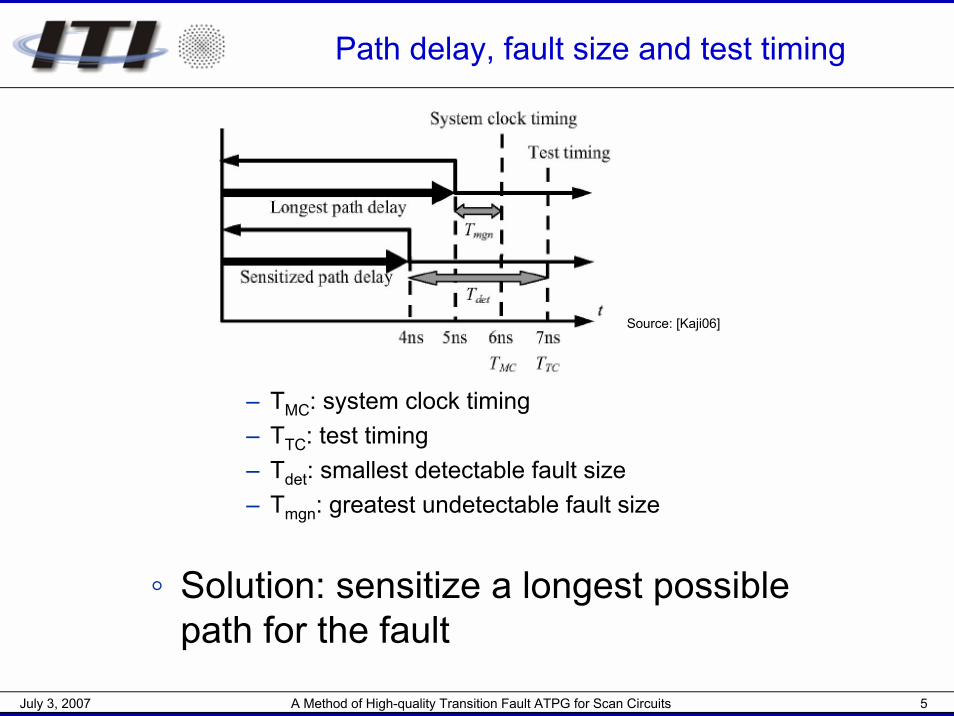
Path delay, fault size and test timing
– TMC: system clock timing– TTC: test timing– Tdet: smallest detectable fault size– Tmgn: greatest undetectable fault size
◦ Solution: sensitize a longest possible path for the fault
Source: [Kaji06]
July 3, 2007 A Method of High-quality Transition Fault ATPG for Scan Circuits 6
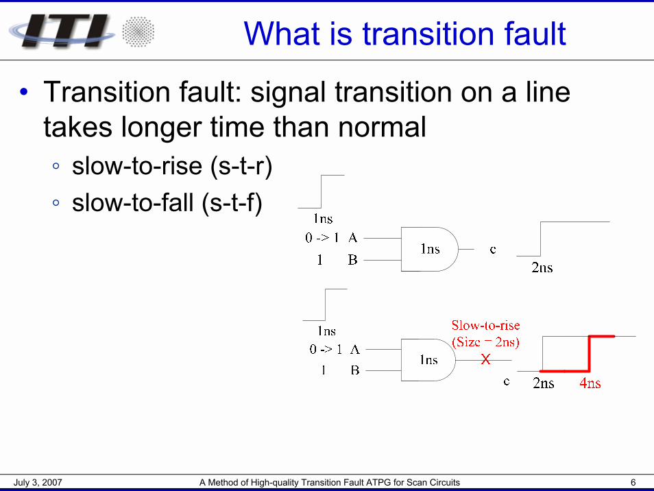
What is transition fault
• Transition fault: signal transition on a line takes longer time than normal◦ slow-to-rise (s-t-r)◦ slow-to-fall (s-t-f)
July 3, 2007 A Method of High-quality Transition Fault ATPG for Scan Circuits 7
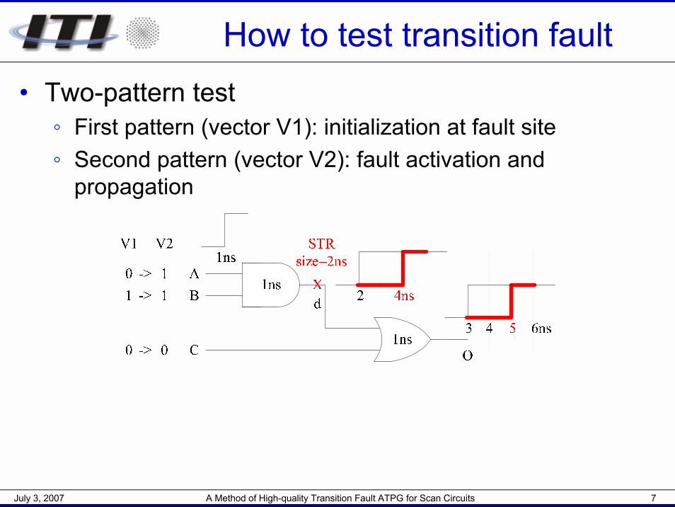
How to test transition fault• Two-pattern test
◦ First pattern (vector V1): initialization at fault site◦ Second pattern (vector V2): fault activation and
propagation
July 3, 2007 A Method of High-quality Transition Fault ATPG for Scan Circuits 8
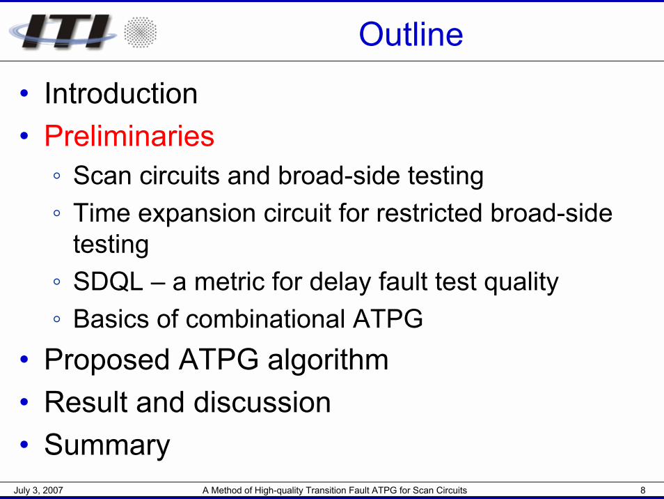
Outline
• Introduction• Preliminaries
◦ Scan circuits and broad-side testing◦ Time expansion circuit for restricted broad-side
testing◦ SDQL – a metric for delay fault test quality◦ Basics of combinational ATPG
• Proposed ATPG algorithm• Result and discussion• Summary
July 3, 2007 A Method of High-quality Transition Fault ATPG for Scan Circuits 9
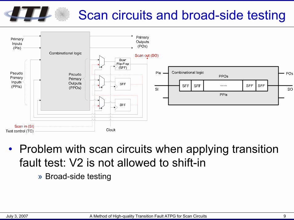
Scan circuits and broad-side testing
• Problem with scan circuits when applying transition fault test: V2 is not allowed to shift-in
» Broad-side testing
July 3, 2007 A Method of High-quality Transition Fault ATPG for Scan Circuits 10
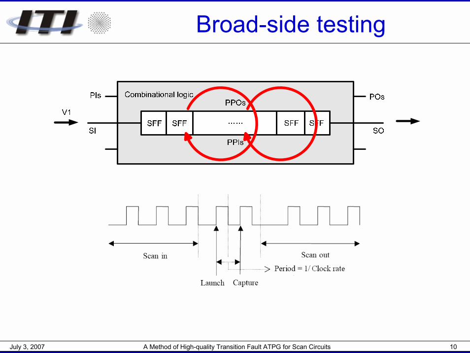
Broad-side testing
July 3, 2007 A Method of High-quality Transition Fault ATPG for Scan Circuits 11
Time expansion circuit for restricted broad-side testing
• Theoretically, we can always have controllability of PIs and observability of POs
• Reality◦ ATEs that support at-speed PI / PO operations are
expensive [Jaya03]◦ When PI / PO counts are relatively low (<200), test
coverage improvement achieved by controlling PI and observing PO is small (<0.2%) [Jaya03]
• Restricted broad-side condition:◦ PIs are not changeable between V1 and V2◦ POs are not observable
July 3, 2007 A Method of High-quality Transition Fault ATPG for Scan Circuits 12
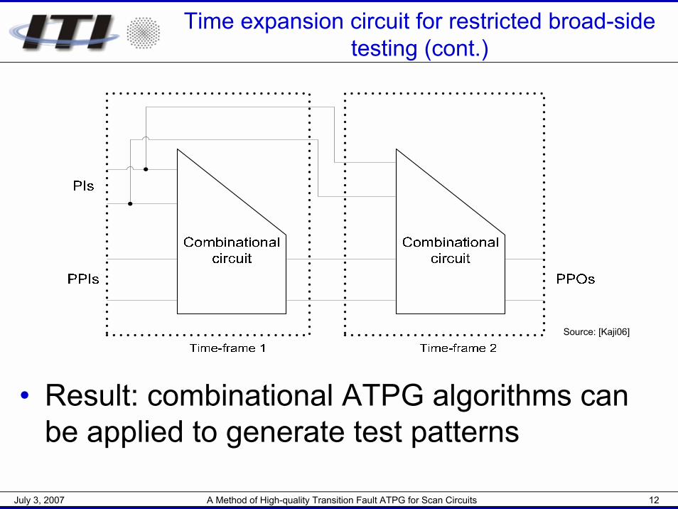
Time expansion circuit for restricted broad-side testing (cont.)
• Result: combinational ATPG algorithms can be applied to generate test patterns
Source: [Kaji06]
July 3, 2007 A Method of High-quality Transition Fault ATPG for Scan Circuits 13
Outline
• Introduction• Preliminaries
◦ Broad-side testing◦ Time expansion circuit for restricted broad-side
testing◦ SDQL – a metric for delay fault test quality◦ Basics of combinational ATPG
• Proposed ATPG algorithm• Result and discussion• Summary

July 3, 2007 A Method of High-quality Transition Fault ATPG for Scan Circuits 14
SDQL – a metric for delay fault test quality
• Assume fault size s
• Tmgn ≤ s < Tdet => fault is undetected !
• Statistical delay quality level (SDQL):
◦ N: number of lines in the circuit◦ F(s): probability distribution of delay
faults with size s» F(s) = a·e-ts + b [Sato05b]
– t: distribution shape parameter– a, b: parameters associated with
defect distribution
det2
1( )
mgn
TN
K T
F s ds=∑ ∫ [Sato05b]
Source: [Kaji06]
July 3, 2007 A Method of High-quality Transition Fault ATPG for Scan Circuits 15
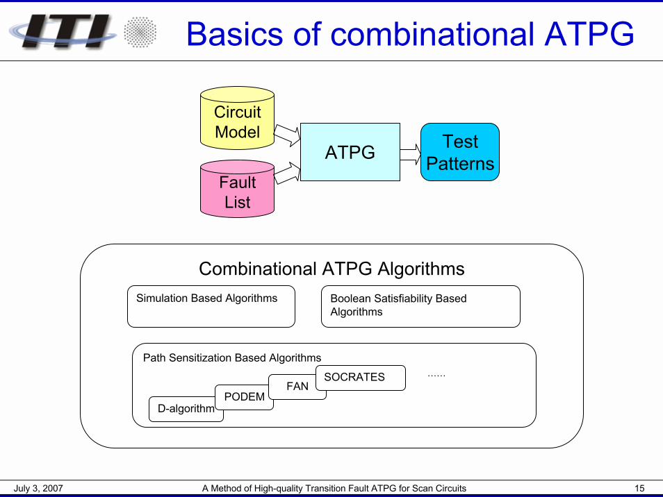
Basics of combinational ATPG
CircuitModel
ATPGFaultList
TestPatterns
Combinational ATPG Algorithms
Path Sensitization Based Algorithms
Simulation Based Algorithms Boolean Satisfiability Based Algorithms
D-algorithmPODEM
FANSOCRATES ……
July 3, 2007 A Method of High-quality Transition Fault ATPG for Scan Circuits 16
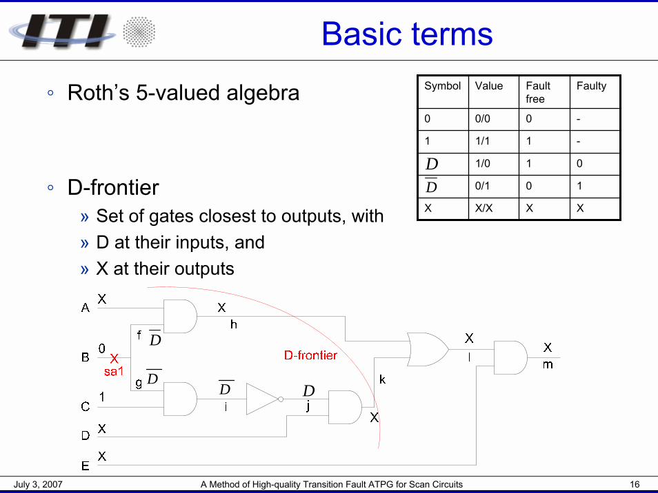
Basic terms
◦ Roth’s 5-valued algebra
◦ D-frontier» Set of gates closest to outputs, with» D at their inputs, and» X at their outputs
Symbol Value Fault free
Faulty
0 0/0 0 -
1 1/1 1 -
1/0 1 0
0/1 0 1
X X/X X X
DD
D
DD
D
July 3, 2007 A Method of High-quality Transition Fault ATPG for Scan Circuits 17
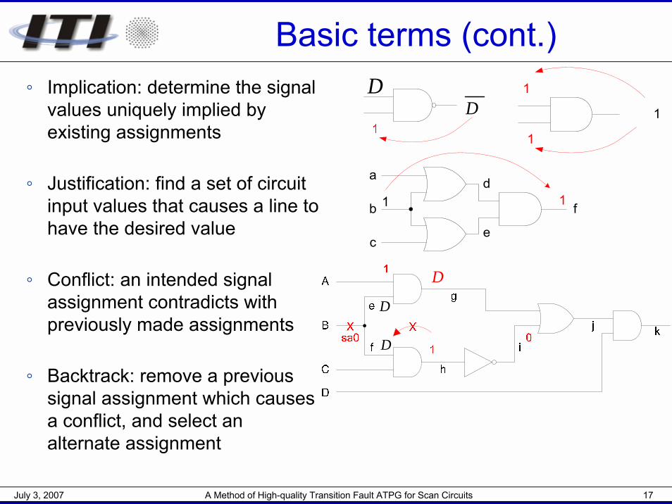
Basic terms (cont.)◦ Implication: determine the signal
values uniquely implied by existing assignments
◦ Justification: find a set of circuit input values that causes a line to have the desired value
◦ Conflict: an intended signal assignment contradicts with previously made assignments
◦ Backtrack: remove a previous signal assignment which causes a conflict, and select an alternate assignment
DD
a
b
c
1d
e
f1
1
1
1
D
D
D
July 3, 2007 A Method of High-quality Transition Fault ATPG for Scan Circuits 18
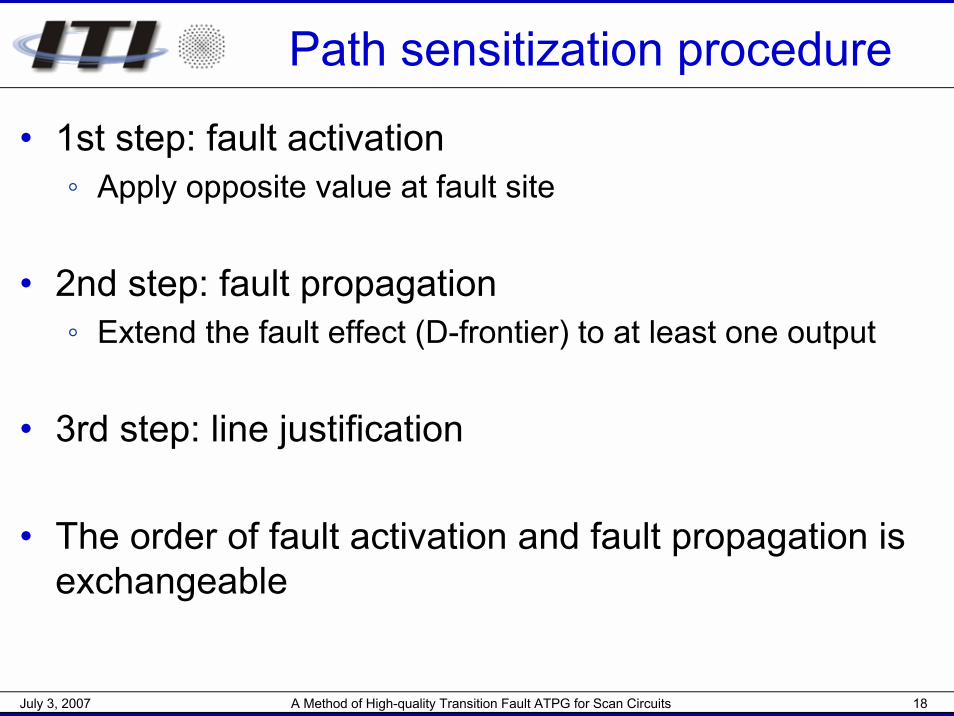
Path sensitization procedure
• 1st step: fault activation◦ Apply opposite value at fault site
• 2nd step: fault propagation◦ Extend the fault effect (D-frontier) to at least one output
• 3rd step: line justification
• The order of fault activation and fault propagation is exchangeable
July 3, 2007 A Method of High-quality Transition Fault ATPG for Scan Circuits 19
Outline
• Introduction• Preliminaries• Proposed ATPG algorithm
◦ Algorithm selection◦ Propagation-first algorithm◦ Activation-first algorithm◦ Overall ATPG procedure
• Result and discussion• Summary
July 3, 2007 A Method of High-quality Transition Fault ATPG for Scan Circuits 20
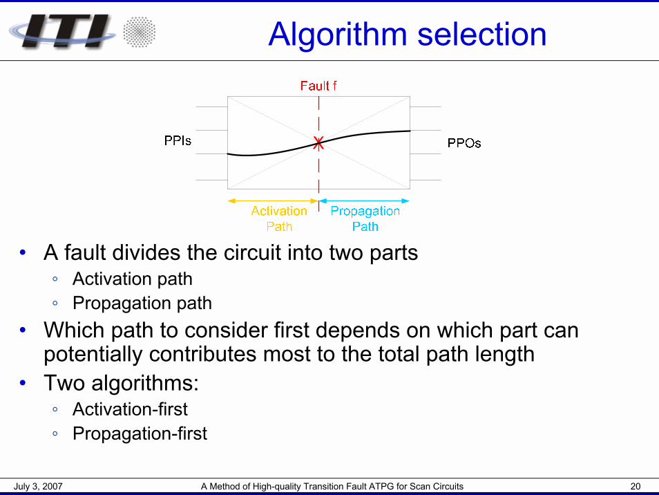
Algorithm selection
• A fault divides the circuit into two parts◦ Activation path◦ Propagation path
• Which path to consider first depends on which part can potentially contributes most to the total path length
• Two algorithms:◦ Activation-first◦ Propagation-first
July 3, 2007 A Method of High-quality Transition Fault ATPG for Scan Circuits 21
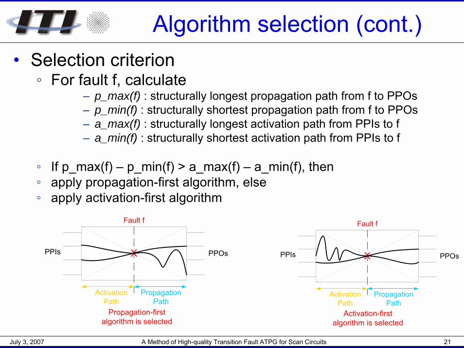
Algorithm selection (cont.)• Selection criterion
◦ For fault f, calculate– p_max(f) : structurally longest propagation path from f to PPOs– p_min(f) : structurally shortest propagation path from f to PPOs– a_max(f) : structurally longest activation path from PPIs to f– a_min(f) : structurally shortest activation path from PPIs to f
◦ If p_max(f) – p_min(f) > a_max(f) – a_min(f), then◦ apply propagation-first algorithm, else◦ apply activation-first algorithm
PPIs PPOsX
Fault f
Activation Path
Propagation Path
Activation-first algorithm is selected
Propagation-first algorithm is selected
PPIs PPOsX
Fault f
Activation Path
Propagation Path
July 3, 2007 A Method of High-quality Transition Fault ATPG for Scan Circuits 22
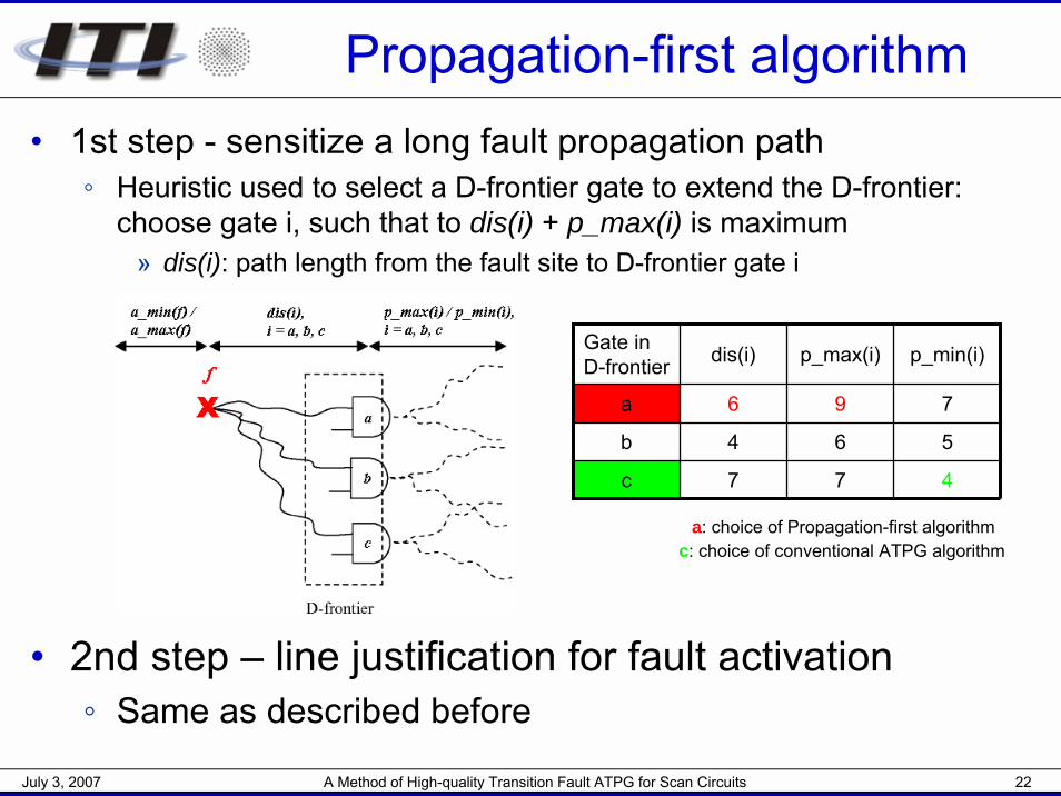
Propagation-first algorithm• 1st step - sensitize a long fault propagation path
◦ Heuristic used to select a D-frontier gate to extend the D-frontier: choose gate i, such that to dis(i) + p_max(i) is maximum
» dis(i): path length from the fault site to D-frontier gate i
Gate in D-frontier dis(i) p_max(i) p_min(i)
a 6 9
6
7
7
b 4 5
c 7 4
• 2nd step – line justification for fault activation◦ Same as described before
a: choice of Propagation-first algorithmc: choice of conventional ATPG algorithm
July 3, 2007 A Method of High-quality Transition Fault ATPG for Scan Circuits 23
Activation-first algorithm• 1st step – find a long fault activation path
◦ Designate the length of fault activation path to be found◦ Expand the path towards PIs by connecting a line with
maximum structural length from PI◦ Each time a path is expanded,
» perform implication procedure– If a conflict occurs, do backtrack
» make sure there exists at least one sensitizable fault propagation path from the fault site to a PPO
– If not, do backtrack
• 2nd step – sensitize a fault propagation path◦ Same as propagation-first algorithm
July 3, 2007 A Method of High-quality Transition Fault ATPG for Scan Circuits 24
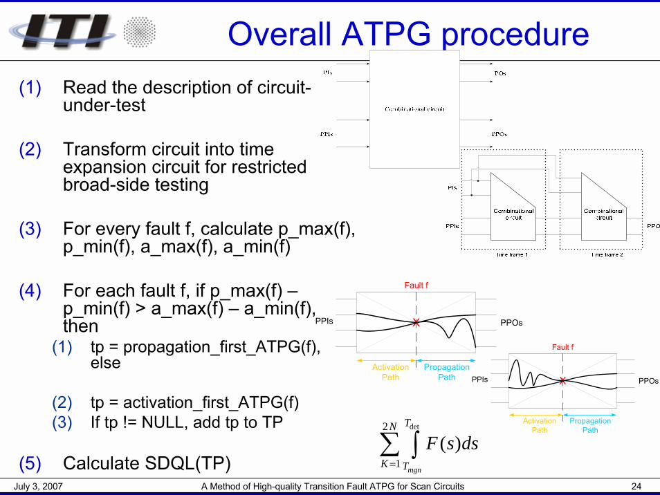
Overall ATPG procedure(1) Read the description of circuit-
under-test
(2) Transform circuit into time expansion circuit for restricted broad-side testing
(3) For every fault f, calculate p_max(f), p_min(f), a_max(f), a_min(f)
(4) For each fault f, if p_max(f) –p_min(f) > a_max(f) – a_min(f), then
(1) tp = propagation_first_ATPG(f), else
(2) tp = activation_first_ATPG(f)(3) If tp != NULL, add tp to TP
(5) Calculate SDQL(TP)
PPIs PPOsX
Fault f
Activation Path
Propagation Path
PPIs PPOsX
Fault f
Activation Path
Propagation Path
det2
1( )
mgn
TN
K T
F s ds=∑ ∫
July 3, 2007 A Method of High-quality Transition Fault ATPG for Scan Circuits 25
Outline
• Introduction• Preliminaries• Statistical delay quality model• ATPG algorithm• Result and discussion• Summary
July 3, 2007 A Method of High-quality Transition Fault ATPG for Scan Circuits 26
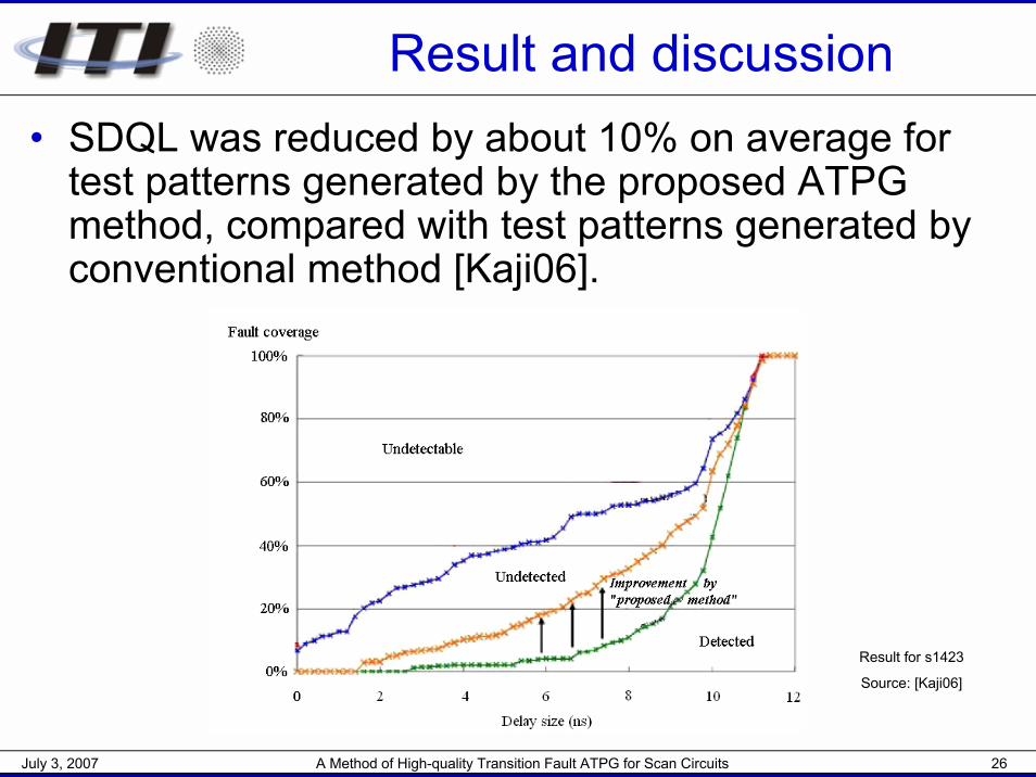
Result and discussion• SDQL was reduced by about 10% on average for
test patterns generated by the proposed ATPG method, compared with test patterns generated by conventional method [Kaji06].
Result for s1423
Source: [Kaji06]
July 3, 2007 A Method of High-quality Transition Fault ATPG for Scan Circuits 27
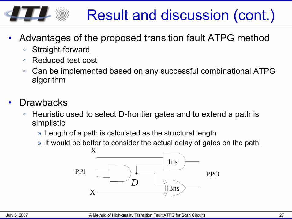
Result and discussion (cont.)• Advantages of the proposed transition fault ATPG method
◦ Straight-forward◦ Reduced test cost◦ Can be implemented based on any successful combinational ATPG
algorithm
• Drawbacks◦ Heuristic used to select D-frontier gates and to extend a path is
simplistic» Length of a path is calculated as the structural length» It would be better to consider the actual delay of gates on the path.
D
X
X
PPI PPO
1ns
3ns
July 3, 2007 A Method of High-quality Transition Fault ATPG for Scan Circuits 28
Result and discussion (cont.)
• Drawbacks◦ During path extension, untestable paths [Bush00]
may be selected» Untestable paths can be identified beforehand and
thus be avoided during path extension, e.g. using the untestable path identification method described in [Shao01]
July 3, 2007 A Method of High-quality Transition Fault ATPG for Scan Circuits 29
Summary• Goal: to sensitize a longest possible path for a small delay fault
• Fault model: transition fault model
• Application of test: broad-side testing
• Circuit for test pattern generation: time expansion circuit for restricted broad-side testing
• Proposed ATPG method contains two algorithms and one selection criterion
• SDQL shows that proposed method can achieve higher test quality
• Several improvements are possible for the proposed ATPG method

Thank you