a method for vibration isolation of a vertical axis automatic washing machine with a hydraulic...
TRANSCRIPT

Journal of Mechanical Science and Technology 26 (2) (2011) 335~343
www.springerlink.com/content/1738-494x DOI 10.1007/s12206-011-0812-2
A method for vibration isolation of a vertical axis automatic washing machine with
a hydraulic balancer† Hai-Wei Chen1, Wei-Xi Ji1,*, Qiu-Ju Zhang1,Yi Cao1 and Sheng-Yao Fan1,2
1School of Mechanical Engineering, Jiangnan University, No.1800 LiHu Rd, Wuxi 214122, Jiangsu Province, China 2Wuxi Institute of Technology, No.1600 Western Gaolang Rd, Wuxi 214121, Jiangsu Province, China
(Manuscript Received March 20, 2011; Revised July 5, 2011; Accepted July 22, 2011)
----------------------------------------------------------------------------------------------------------------------------------------------------------------------------------------------------------------------------------------------------------------------------------------------
Abstract This paper discusses a method for vibration isolation of a vertical axis automatic washing machine with a hydraulic balancer. First, a
way to isolate vibration through a small amplitude of the suspension rod’s axial force is proposed, and a base circle of a cone along which the lower joint of a suspension rod moves is discussed. Based on the circle, a geometric constraint involving the slant angle of the suspen-sion rod, the deflection angle of the washing/spinning assembly, the suspension radius of the tub and the eccentricity of the system at the steady state is derived. Considering that the trace along which the suspension rod moves is also affected by the dynamics of the system, a governing equation satisfying the equilibrium conditions of the centrifugal forces and torques is obtained. Combing the geometric con-straint and governing equation together achieves a general governing equation for vibration isolation of the system. Finally, the general governing equation is proven by simulations, and the relations between the optimal installing height and several parameters are discussed.
Keywords: Hydraulic balancer; Suspension rod; Vibration isolation; Washing machine ---------------------------------------------------------------------------------------------------------------------------------------------------------------------------------------------------------------------------------------------------------------------------------------------- 1. Introduction
Strong vibration often occurs due to clumped clothes in the spin drying process of a vertical axis automatic washing ma-chine. The random distribution of clothes makes vibration suppression difficult. An effective way is to employ a dy-namic balancer that counteracts the clothes automatically. Thus, a hydraulic balancer is often used in the vertical axis automatic washing machine.
So far, research on the vibration suppression of the vertical axis automatic washing machine has been focused on the sta-bility and steady-state response of the spin drying process. Employing the continuation and bifurcation software AUTO [1], Ref. [2] analyzed the stability of the spin drying process when the hydraulic balancer is not considered. A mathemati-cal model involving both tangential and axial damping forces of the suspension system was built, and a Hopf bifurcation phenomenon due to a small tangential damping coefficient was identified. Due to the complexity of a hydraulic balancer, rigid balls are often used to simulate the effect of the liquid in the balancer to analyze the transience or stability of the spin drying process when the hydraulic balancer is involved. It has
been proven that this method can achieve qualitative results. Ref. [3] used three balls to describe the effect of the hydraulic balancer and presented the similarities between the results of simulations and experiments. Lately, Ref. [4] employed a two-ball model to analyze the stability of the spin drying process of a washing machine with a hydraulic balancer. Two unstable regions denoted by M and N were identified and the unstable region N is discussed in detail with its existence proven by both simulation and experiment. A numerical model for the balancer has to be built to analyze the steady-state response of the spin drying process. Thus, Ref. [5] built a numerical de-scription of the liquid in the balancer and then discussed its influence on the steady-state response of the spin drying proc-ess. Employing the same model, Ref. [6] proposed a new ap-proach for analyzing the steady-state response of the spin dry-ing process and discussed a method for obtaining a small de-flection angle of the washing/spinning assembly at the steady state.
The structure of a vertical axis automatic washing machine is shown in Fig. 1(a). This consists of a cabinet, a suspension system and a washing/spinning assembly. The assembly is connected to the cabinet through a suspension system with four suspension rods whose structures are shown in Fig. 1(b). As can be seen, each suspension rod contains two spherical joints: a rod and a damping tub. During the spin drying proc-ess, the suspension rod can swing and stretch simultaneously.
† This paper was recommended for publication in revised form by Editor Yeon June Kang
*Corresponding author. Tel.: +86 18762616791, Fax.: +86 051085706799 E-mail address: [email protected]
© KSME & Springer 2012

336 H.-W. Chen et al. / Journal of Mechanical Science and Technology 25 (11) (2011) 335~343
Thus, both tangential and axial forces could be aroused. Although the hydraulic balancer is effective for vibration
suppression at the steady state of the spin drying process, it does not have the capability of complete balance. What’s more, for a vertical axis automatic washing machine, the con-dition is even worse because the hydraulic balancer and the clothes usually lie in different horizontal planes. Thus, com-plete balance of the system using only one single balance is unlikely. Furthermore, vibrations are often transmitted to the cabinet through the suspension system, which may result in further vibrations of the cabinet. This vibration may arouse serious noise of the cabinet or cause great discomfort when users put their hands on the surface of the cabinet. Today, low noise and low vibration have become two of the most impor-tant performance characters of a washing machine. To reduce vibrations of the cabinet, good vibration isolation of the sys-tem is required. An effect way to do this is to control the am-plitude of the axial forces transmitted to the cabinet. This pa-per will present such a method.
During the process of designing a hydraulic balancer, de-signers usually concentrate their efforts on the centrifugal forces it generates but pay little attention to the balancer’s installing height. Actually, according to Ref. [6], at the steady
state of the spin drying process, there are two equilibrium conditions that should be noted: one is the equilibrium condi-tion of the centrifugal forces and the other is that of the cen-trifugal torques. To emphasize the importance of the latter condition and stress the effect of the centrifugal torques gener-ated by the hydraulic balancer, mainly the installing height of the balancer will be discussed in this paper.
2. Vibration isolation of a vertical axis automatic
washing machine
2.1 Method to control the amplitude of the axial force trans-mitted by a suspension rod
Axial forces of the suspension system are the primary forces among those transmitted to the cabinet that are responsible for the cabinet’s vibration. An effective method for vibration iso-lation is to control the amplitudes of these forces. If these forces do not vary, there will be constant forces acting on the cabinet, which is ideal for vibration isolation. We now analyze the axial forces. As can be seen from Fig. 1(b), the axial force of a suspension rod is composed of two parts: one is the re-storing force of the spring and the other is the axial damping force provided by the damping tub. The axial force of the suspension rod can be described as
( )0a s aF K l l C l= − − & (1)
where sK is the stiffness coefficient of the spring, aC is the axial damping coefficient of the damping tub, l is the dis-tance between the upper and lower spherical joints and 0l is the initial length of the rod at the equilibrium position. Let 0x l l= − , the above equation could be expressed as
a s aF K x C x= − & . (2)
Considering at the steady state of the spin drying process,
the variable x could be expressed as 0 sinx X t= Ω where 0X is the vibration amplitude and Ω is the rotation speed.
Substituting 0 sinx X t= Ω into Eq. (2) yields
0 0sin cosa s aF K X t C X t= Ω − Ω Ω . (3) Based on the above equation, the amplitude of the axial
force can be derived as
( ) ( ) ( )2 2 220 0 0s a s aA K X C X X K C= + Ω = + Ω . (4)
As can be seen, if the stiffness coefficient sK ,damping co-
efficient aC and rotation speed Ω are set, the vibration am-plitude 0X must be designed to be as small as possible in order to achieve a small amplitude for the axial force A . If 0X turns zero, the amplitude of the axial force A will be zero as well, which is ideal for vibration isolation. Be-
Suspension rod
Tub
Cabinet
HydraulicBalancer
Basket
Motor and Clutch
A
rX
rY
rZ bZ
rO
bY
bXα
β
γ
bO
(a)
Rod
Upperspherical joint
Damping tub
Tub
Cabinet
Lowerspherical joint
(b)
Spring
Fig. 1. (a) Structure of a vertical axis automatic washing machine; (b)structure of a suspension rod.

H.-W. Chen et al. / Journal of Mechanical Science and Technology 25 (11) (2011) 335~343 337
cause 0 0 sinx l l X t= − = Ω , once 0X equals zero, the dis-tance between the upper and lower spherical joints l will be equal to the constant length 0l . At this condition, considering that the upper spherical joint of the suspension rod is fixed, in order to keep 0l l= , the lower spherical joint must move along a special trajectory, such as the surface of a sphere with the upper joint as the center and 0l as the radius, or the base circle of a right circular cone as shown in Fig. 2(a) with the upper joint as the vertex and 0l as the generatrix. At these conditions, because the length of the suspension rod does not change, the axial force of the suspension rod stays constant, which is ideal for vibration isolation.
Fig. 2(b) displays simulations of the traces of a suspension rod at the steady state of the spin drying process when the amplitude of the axial force is small. As can be seen, the tra-jectory of the suspension rod nearly forms the lateral surface of a right circular cone shown in Fig. 2(a) with the upper joint U as the vertex and 0l as the generatrix, and the trace along which the lower joint D moves trends to the base circle of a cone whose radius depends on the eccentricity of the system and the deflection angle of the tub. In the figure, UH is the axis of the cone. At the static equilibrium position of the sys-tem, the suspension rod lies in the position UH, and the angle between UH and the vertical line is the slant angle of the sus-pension rodϕ .
We now present a governing equation to obtain a small am-plitude for the rod’s axial force based on the trace displayed in Fig. 2. Assume that the vibration period of the wash-ing/spining assembly is T. As Fig. 3(a) shows, at first ( 0t = ), the washing/spinning assembly lies in the position 1 1 1 1A B C D and the suspension rod lies in 1UD . Suppose that the lower joint D moves exactly along the base circle of the cone shown in Fig. 2(a). After T/4 seconds ( / 4t T= ), the wash-ing/spinning assembly will move to the position ABCD and the suspension rod will move to UD . In Fig. 3(a), UH is the axis of the cone and the projections of points H and D co-incide. After another T/4 seconds ( / 2t T= ), the wash-ing/spinning assembly will move to the position 2 2 2 2A B C D shown in Fig. 3(b) and the suspension rod will move to 2UD .
In the figure, the point O is the suspension center of the assembly. As time passes, it first moves from 1O to O , and then from O to 2O . Note that 1O , O , 2O and H lie in the same line at the steady state of the spin drying process. The distance from 1O to O equals that from O to 2O ; namely,
1 2O O OO e= = . Here, e denotes the eccentricity of the sys-tem at the steady state. In Fig. 3(b), the two angles 1 1D O E∠ and 2 2D O E∠ are identical; namely, 1 1 2 2D O E D O E φ∠ = ∠ = . Here, φ denotes the deflection angle of the washing/spining assembly at the steady state, which can be described as 2 2φ α β= + where α and β are the Cardan’s angles in Fig. 1(a) that are used to describe the assembly’s posture. In Fig. 3(b), the angle HUE ϕ∠ = is the slant angle of the sus-pension rod discussed in Fig. 2(a).
Asymmetry of the washing/spinning assembly is neglected and the slant angles of the four suspension rods are assumed to be identical. We now explore the relation between the slant angle of the suspension rod ϕ and the deflection angleφ of the washing/spinning assembly. In Fig. 3(b), a line is drawn through 1D that is perpendicular to the line OE and inter-sects it at point P . We now analyze the length of the line HP . As Fig. 3(b) reveals, for the triangle 1 1O D HΔ , based on the Law of Cosines, the following relation exists:
( ) ( )
2 2 2
1 1 1 1 1 1 122
1 1 2 2 1 1
2 cos
2 2 2 cos
D H D O HO HO D O
D O HO e HO e D O
φ
φ
= + −
= + + − +. (5)
Similarly, for the triangle 2 2O HDΔ , the following equation
Base circle
Upper joint U
Lower joint D
0l
H
ϕ
Vertical line
(a) (b) Fig. 2. The traces along which the lower joint moves: (a) base circle of a right circular cone; (b) simulation result.
O1
D1
U
A1
B1
C1 B
H,D OA
C
φ
(a)
O1O2
D1
D2
UC2
P
α
A1
B1
C1
A2
B2
HE φ
Oee
(b) (b)
Fig. 3. Traces of the washing/spinning assembly.

338 H.-W. Chen et al. / Journal of Mechanical Science and Technology 25 (11) (2011) 335~343
can be derived:
2 2 2
2 2 2 2 2 2 22 cosD H HO D O HO D O φ= + − . (6) In the above equations, because both 1D H and 2D H are
the base radii of the cone, they are identical; 1 2D H D H= . Furthermore, because both 1 1D O and 2 2D O are suspension radii of the tub, they are also identical; 1 1 2 2D O D O= . Substi-tuting 1 2D H D H= , 1 1 2 2D O D O= into the above equations and then subtracting Eq. (5) by Eq. (6) yields
1 1 2cosD O HO eφ = + . (7)
Based on the triangle 1 1D O PΔ , the item 1 1 cosD O φ in the above equation can also be expressed as
1 1 1 2cos 2D O O P O P eφ = = + . (8) Subtracting Eq. (7) by Eq. (8) yields
2 2O P HO e= − . (9) As can be seen from Fig. 3(b), the item 2O P in Eq. (9) can
be also described as
2 2O P HO HP= − . (10) Comparing Eqs. (9) and (10), the length of the line HP can
be achieved as HP e= . (11)
We now derive the relation between the slant angle of the
suspension rod ϕ and the deflection angle of the wash-ing/spinning assemblyφ based on HP . As can be seen from Fig. 3(b), the sum of the two angles 2D HE∠ and EHU∠ is 90°,
2 90oD HE EHU∠ +∠ = (12)
and the sum of the two angles EUH∠ and EHU∠ is also 90°,
90oEUH EHU EHUϕ∠ +∠ = +∠ = . (13)
Based on Eqs. (12) and (13), the angle 2D HE∠ can be
described as
2D HE ϕ∠ = . (14) As Fig. 3(b) reveals, because 2D HE∠ and 1D HP∠ are
vertical angles, they are identical,
1 2D HP D HE ϕ∠ = ∠ = . (15) Now, the tangent value of 1D HP∠ can be expressed as
1 1 11
sintan tan D P D OD HPHP HP
φϕ∠ = = = . (16)
Let 1 1D O r= . Then, substituting 1 1D O r= and HP e=
into the above equation yields the following equation: sin tan
e rφ ϕ= (17)
whereφ and e are the deflection angle and eccentricity of the washing/spinning assembly at the steady state, respec-tively. ϕ is the slant angle of the suspension rod shown in Fig. 2(a) which can be measured at the static equilibrium posi-tion of the system. r is the suspension radius of the tub.
Eq. (17) is a geometric constraint that guarantees that the lower joint of the suspension rod moves exactly along the base circle of the cone shown in Figs. 2 and 3. At this condition, because the length of the suspension rod does not vary, the axial force of the suspension rod stays constant, which is ideal for vibration isolation. As can be seen from Eq. (17), once the suspension radius of the tub r and the slant angle of the suspension rod ϕ are set, the ratio between sinφ and e has to be specially designed. Actually, this ratio is influenced by the equilibrium conditions of the centrifugal forces and torques acting on the washing/spinning assembly. We will now discuss these conditions. At the steady state of the spin drying process, the rotation speed of the system is very high, and centrifugal forces acting on the washing/spinning assem-bly are much larger than the forces provided by the suspension system. Thus, only centrifugal forces are considered in the following sections.
Centrifugal forces acting on the washing/spinning assembly at the steady state are displayed in Fig. 4(a): U represents the clumped clothes; C is the centroid of the liquid; P is mass center of the washing/spinning assembly (excluding the clothes and the liquid in the balancer); rZ -axis is the axis around which the system rotates at the steady state; S-axis is the symmetric axis of the assembly; A is the suspension plane of the tub; φ is the deflection angle of the washing/spinning assembly which equals to the angle 1 1D O E∠ or 2 2D O E∠ shown in Fig. 3; tF , uF and hF are centrifugal forces acting on the clothes, liquid and washing/spinning assembly, respec-tively. We will now express tF , uF and hF one by one.
First, we analyze the centrifugal force acting on the wash-ing/spinning assembly tF shown in Fig. 4(b). As the figure shows, th is the height of the washing/spinning assembly’s mass center P relative to the suspension plane A; φ is the deflection angle of the washing/spinning assembly; O and
1O denote the suspension center of the tub; e is the distance from O to 1O , which is the eccentricity of the system at the

H.-W. Chen et al. / Journal of Mechanical Science and Technology 25 (11) (2011) 335~343 339
steady state. The centrifugal force tF in Fig. 4(b) can be de-scribed as
( ) 2sint t tF m e h φ= + Ω (18)
where Ω denotes the rotation speed of the system at the steady state. The torque generated by tF relative to point O can be described as
cost t tM F h φ= . (19)
Second, we analyze the centrifugal force hF that acts on the
liquid in the balancer. Based on the derivation of Eq. (14) in Ref. [6], hF can be expressed using Fig. 4(c) where hh is the installing height of the balancer relative to the suspension plane A. As can be seen, hF can be described as
( ) ( )( )2 2sin sin 1h h h h hF m e h c m e hφ φ η= + + Ω = + + Ω (20)
where ( )/ sinhc e hη φ= + . The torque generated by hF rela-tive to point O can be described as
cosh h hM F h φ= . (21)
Third, we discuss the centrifugal force uF shown in Fig.
4(d) that acts on the clothes U . As the figure reveals, uh is the height of the clothes relative to the suspension plane A , and uR is the gyration radius of the clothes. As can be seen from Fig. 4(d), uF can be described as
2u uF m UL= Ω (22)
where
( )tan sincos
uu u
RUL UN LM MN e h R φ φφ
= − − = − − + . (23)
When the deflection angleφ is small, the item tanuR φ in
Eq. (23) is much smaller than uh , and thus Eq. (23) can be simplified as
sincos
uu
RUL e h φφ
= − − . (24)
In Fig. 4(d), the torque generated by uF relative to point
O can be described as
( )tan cosu u u uM F h R φ φ= + . (25)
Neglecting the item tanuR φ , the above equation can be
simplified as
cosu u uM F h φ= . (26) We now describe the equilibrium conditions governed by
the above forces or torques. The equilibrium condition of the centrifugal forces in Fig. 4(a) can be expressed as
t h uF F F+ = . (27)
Submitting Eqs. (18), (20) and (22) into the above equation
yields
( ) ( )( )2 2
2
sin sin 1
sincos
t t h h
uu u
m e h m e h
Rm e h
φ φ η
φφ
+ Ω + + + Ω
⎛ ⎞= − − Ω⎜ ⎟
⎝ ⎠
(28)
from which the following equation can be derived
( )
( )
1
1 sincos
t h u
uu u u h h t t
m m m e
Rm m h m h m h
η
η φφ
⎡ ⎤+ + +⎣ ⎦
⎡ ⎤= − + + +⎣ ⎦. (29)
We now analyze the equilibrium condition of the torques.
As can be seen from Fig. 4(a), the equilibrium condition of the torques can be expressed as
t h uM M M+ = . (30)
Substituting Eqs. (19), (21) and (26) in the above equation
yields
Fu
Fh
hu
hh
c
Ru
Zr S
U
C
Mu
Mh
Ftht
P Mt
φ
A e
O
S
Ft
ht
P
φ
E O1
Zr
A
e
O
S
Fh
hh
C
φ
E
O1
c
A
Zr
e
O
SFu
huφ
E
O1
Ru
φU NL M
Zr
A
(a)(b)
(c) (d)
Mt
Mh Mu
Fig. 4. Centrifugal forces acting on the washing/spinning assembly.

340 H.-W. Chen et al. / Journal of Mechanical Science and Technology 25 (11) (2011) 335~343
( ) ( )( )2 2
2
sin cos sin 1 cos
sin coscos
t t t h h h
uu u u
m e h h m e h h
Rm e h h
φ φ φ η φ
φ φφ
+ Ω + + + Ω
⎛ ⎞= − − Ω⎜ ⎟
⎝ ⎠
(31) from which the following equation can be derived
( )
( )2 2 2
1
1 sincos
t t h h u u
uu u u u t t h h
m h m h m h e
Rm h m h m h m h
η
η φφ
⎡ ⎤+ + +⎣ ⎦
⎡ ⎤= − + + +⎣ ⎦. (32)
Subtracting Eq. (32) by the product of Eq. (29) times uh ,
namely, (32) (29) uh− × , yields
( ) ( )( )( ) ( )( )
1
1 sin
t t u h h u
t t u t h h u h
m h h m h h e
m h h h m h h h
η
η φ
⎡ ⎤− + + −⎣ ⎦⎡ ⎤= − + + −⎣ ⎦
. (33)
After a further derivation, the following relation between
sinφ and e can be achieved
( ) ( )( )( ) ( )( )
1sin1
t t u h h u
t t u t h h u h
m h h m h he m h h h m h h h
ηφη
− + + −=
− + + −. (34)
Eq. (34) is a governing equation of the system based on dy-
namics that satisfies the equilibrium conditions of centrifugal forces and torques. As can be seen, the ratio between sinφ and e is governed by this equation. Recall that the ratio be-tween sinφ and e is also governed by the geometric con-straint described by Eq. (17) that guarantees a small amplitude of the axial forces. Substituting Eq. (17) into Eq. (34), a gen-eral governing equation for vibration isolation of the system can be obtained
( ) ( )( )( ) ( )( )
1tan1
t t u h h u
t t u t h h u h
m h h m h hr m h h h m h h h
ηϕη
− + + −=
− + + −. (35)
Parameters governed by Eq. (35) mean that the lower joint
of the suspension rod moves along the base circle of the cone shown in Figs. 2 and 3, which implies a small amplitude of the axial force and, thus, is ideal for vibration isolation of the sys-tem. As can be seen from Eq. (35), if the slant angle of the suspension rod ϕ , the suspension radius of the tub r and the height of the clothes uh are set, to obtain a small ampli-tude of the axial force, the mass of the washing/spinning as-sembly tm , the height of the assembly’s mass center th , the mass of the liquid in the hydraulic balancer hm ,the install-ing height of the balancer hh and the ratio of the hydraulic balancer η have to be specially designed.
2.2 Discussion
Two equilibrium conditions of the system at the steady state
should be noted while designing a hydraulic balancer for the vertical axis automatic washing machine. One is the equilib-rium condition of the centrifugal forces described by Eq. (27), and the other is the equilibrium condition of the centrifugal torques governed by Eq. (30). Usually, designers concentrate their efforts on the first condition but pay little attention to the second one. Thus, to stress the later condition, the installing height of the balancer is mainly discussed in this section. Let
tan / rδ ϕ= . After a further derivation of Eq. (35), the opti-mal installing height of the hydraulic balancer can be achieved as
( ) ( )2
*1/ 1/ 4
2u u
h
h hh
δ δ− − + − + Δ= (36)
where
( )( )
( )1
1t u t tu
h
m h h hhm
δδ η δ
− +Δ = +
+. (37)
We now validate this result using numerical simulations.
Take a washing machine as an example: the mass of the wash-ing/spinning assembly 10.615Kgtm = , the height of the assembly’s mass center 0.0075mth = − , the outer radius of the hydraulic balancer 0.2moR = and the inner radius of the balancer 0.16miR = . To calculate the optimal installing height *
hh , the two parameters relating to the balancer hm and η in Eq. (37) have to be set. To maintain a larger linear region for the hydraulic balancer, the optimal volumetric ratio of the balancer described by Eq. (51) in Ref. [6] is adopted:
( )22*
2 2
/ 4o o i
o i
R R Rq
R R
− +=
−. (38)
Submitting 0.2moR = and 0.16miR = into the above equa-
tion yields * 0.5278q = . Assuming the capacity of the balan-cer is 1.3 Kg , the mass of the liquid in the balancer can be calculated as 1.3 0.5278 0.686 Khm g= × = . In the linear region, the ratio of the balancer η can be described using Eq. (4) in Ref. [6] as
2
2 2s
o s
RsR R
η = =−
(39)
where ( )2 2 2
s o o iR R q R R= − − . Substituting 0.2 moR = , 0.16 miR = , * 0.5278q = into sR and then submitting oR and sR into Eq. (39) yields
4.263sη = = . Assume the height of the clothes 0.1 muh = . To obtain the optimal installing height of the balancer de-scribed in Eq. (36), the variable tan / rδ ϕ= , which depends on the suspension radius of the tub r and the tangent value of the slant angle of the suspension rod ϕ , has to be calcu-lated. The suspension radius r can be easily measured as
H.-W. Chen et al. / Journal of Mechanical Science and Technology 25 (11) (2011) 335~343 341
r =0.26 m. The problem is how to obtain tanϕ . To find tanϕ , the lengths of the lines UE and EH in Fig. 3(b), which depend on the static equilibrium position of the system, have to be obtained. It should be noted that in order to let the sus-pension rod lie exactly in the position UH at the static equi-librium position, the clothes should at first lie in the center of the basket. In other words, the gyration radius of the clothes uR should be zero while solving the static equilibrium position.
The static equilibrium position can be solved by static or dynamic methods. This paper employs a simple dynamic me-thod. Let the mass of the clothes um =1 Kg, the gyration ra-dius of the clothes uR =0m, and rotation speed of the basket Ω =0Hz. Assume the initial position of the system is
0 0 0 0.33 0 0 0 .T= ⎡ ⎤⎣ ⎦q Calculations are carried
out by applying the ode45 function in MATLAB on the vibration model described by Eq. (21) in Ref. [6]. After 10 seconds, the value of q stays still and the result shows
* 0 0 0.3125 0 0 0 T= ⎡ ⎤⎣ ⎦q . Based on the result, the
lengths of the lines UE and EH can be obtained as UE =0.4475 and EH =0.0933m. Now, the tangent value of the slant angle of the suspension rod ϕ can be obtained as tan / 0.209EH UEϕ = ≈ . Considering the radius of the tub 0.26,r = the variable δ can be easily calculated as
tan / 0.802rδ ϕ= ≈ . Substituting the valve of δ and all the parameter values listed above into Eq. (36), the optimal in-stalling height of the hydraulic balancer can be calculated as
*hh ≈ 0.346 m. It can be seen from the above discussion that the static equi-
librium position of the system is influenced by the mass of the clothes um , and because the slant angle of the suspension rod ϕ depends on the static equilibrium position, the optimal installing height of the hydraulic balancer *
hh is affected by the mass of clothes um . However, this influence can be ne-glected in the interval 0,2um ∈⎡ ⎤⎣ ⎦ . Calculations show that the interval of the optimal installing height *
hh corresponding to 0,2um ∈⎡ ⎤⎣ ⎦ is * [0.3458,0.3461]hh ∈ , which is very small. As
can be seen, the value of *hh in the interval is about 0.346
meters. When the parameter values listed above are considered, the
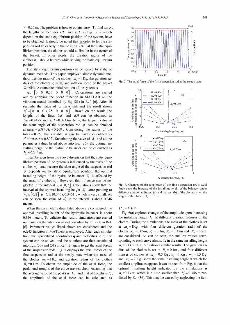
optimal installing height of the hydraulic balancer is about 0.346 meters. To validate this result, simulations are carried out based on the vibration model described by Eq. (21) in Ref. [6]. Parameter values listed above are considered and the ode45 function in MATLAB is employed. After each simula-tion, the generalized coordinates q and velocities q& of the system can be solved, and the solutions are then substituted into Eqs. (30) and (31) in Ref. [2] again to get the axial forces of the suspension rods. Fig. 5 displays the axial forces of the first suspension rod at the steady state when the mass of the clothes um =1 Kg and gyration radius of the clothes
uR =0.1 m. To obtain the amplitude of the axial force, the peaks and troughs of the curve are searched. Assuming that the average value of the peaks is pF and that of troughs is tF , the amplitude of the axial force can be calculated as
( ) / 2p tF F− . Fig. 6(a) explores changes of the amplitude upon increasing
the installing height hh at different gyration radiuses of the clothes. During the simulations, the mass of the clothes is set at 1Kgum = with four different gyration radii of the clothes; 0.05m,uR = 0.1m,uR = 0.15muR = and 0.2muR = are considered. As can be seen, the smallest values corre-sponding to each curve almost lie in the same installing height
hh =0.33 m. Fig. 6(b) shows similar results. The gyration ra-dius of the clothes is set at 0.1muR = , and four different masses of clothes at 0.5 Kgum = , 1 Kgum = , 1.5 Kgum = and 2 Kgum = show the same installing height at which the smallest amplitudes appear. It can be seen from Fig. 6 that the optimal installing height indicated by the simulations is
hh =0.33 m, which is a little smaller than * 0.346 mhh = pre-dicted by Eq. (36). This may be caused by neglecting the item
Peak
TroughTime [s]
The
axia
l for
ce [N
]
2 ≠
Am
plitu
de
Fig. 5. The axial force of the first suspension rod at the steady state.
hh=0.33m
hh=0.33m
The instaling height hh [m]
(a)
(b)
Am
plitu
de o
f the
firs
tsu
pens
ion
rod'
s axi
al fo
rce
[N]
The instaling height hh [m]
Am
plitu
de o
f the
firs
tsu
pens
ion
rod'
s axi
al fo
rce
[N]
Fig. 6. Changes of the amplitude of the first suspension rod’s axial force upon the increase of the installing height of the balancer under different gyration radiuses: (a) and masses; (b) of the clothes when the height of the clothes 0.1muh = .

342 H.-W. Chen et al. / Journal of Mechanical Science and Technology 25 (11) (2011) 335~343
tanuR φ in Eqs. (23) and (25). To prove this, the height of the clothes is changed to 0.15muh = and the optimal installing height corresponding to it can be calculated using Eq. (36) as
* 0.482 mhh = . Fig. 7(a) shows the simulation results when the mass of the clothes 1 Kgum = , and Fig. 7(b) shows the results when the gyration radius of the clothes 0.1 muR = . Both figures show the same installing height 0.48 mhh = at which the smallest amplitudes appear. It can be seen that the height 0.48 mhh = is very close to * 0.482 mhh = predicted by Eq. (36). Besides, as can be seen from Figs. 6 and 7, the optimal installing heights are hardly affected by the mass or gyration radius of the clothes.
We now make a comparison between the optimal installing height of the hydraulic balancer discussed in this paper and that discussed in Ref. [6]. The optimal installing height dis-cussed in this paper corresponds to a small amplitude of the axial force of the suspension system, which is helpful for vi-bration isolation, while the installing height discussed in Ref. [6] corresponds to a small deflection angle of the wash-ing/spinning assembly that could leave more space for pre-venting collisions between the assembly and the cabinet. The two heights are different. Take the following parameter values for example: when the mass of the clothes um =1 Kg , the gyration radius of the clothes uR =0.1 m and the height of the clothes 0.1uh = m, the optimal installing height for vibration isolation is 0.346 m while that for a small deflection angle is 0.416 m. As can be seen, the former is a little smaller than the later. This means a small deflection angle of the wash-
ing/drying assembly is not sufficient enough for vibration isolation of the system.
We now discuss influences of the slant angle ϕ and the suspension radius of the tub r on the optimal installing height *
hh . Calculations are carried out based on Eqs. (36) and (37). Fig. 8(a) shows the relation between the installing height
*hh and the slant angle ϕ when the suspension radius of the
tub 0.26 mr = . As can be seen, a larger slant angle ϕ cor-responds to a lower installing height *
hh . Fig. 8(b) displays changes of the optimal installing height *
hh upon the varia-tions of the suspension radius of the tub r when the slant angle 11.8Degϕ = . As can be seen, the optimal installing height of the balancer changes larger when the suspension radius of the tub increases.
We now discuss the influence of the item ( )1hm η+ in Eq. (37) on the optimal installing height of the balancer *
hh . Ac-cording to Eq. (55) in Ref. [6], in the linear region of the hy-draulic balancer, the item ( )1hm η+ can be described as
( ) 21 h om hRχ η ρπ= + = (40)
where ρ is density of the liquid, h is the depth of the bal-ancer and oR is the outer radius of the balancer. Substituting Eq. (40) into Eq. (37) yields
( )( )1t u t tu m h h hh δ
δ χδ− +
Δ = + . (41)
hh=0.48m
hh=0.48m
(a)
(b)
The instaling height hh [m]
The instaling height hh [m]
Am
plitu
de o
f the
firs
tsu
pens
ion
rod'
s axi
al fo
rce
[N]
Am
plitu
de o
f the
firs
tsu
pens
ion
rod'
s axi
al fo
rce
[N]
Fig. 7. Changes of the amplitude of the first suspension rod’s axialforce upon the increase of the installing height of the balancer underdifferent gyration radiuses: (a) and masses; (b) of the clothes when theheight of the clothes 0.15 muh = .
The slant angle of the suspension rod [Deg]
T
he o
ptim
al in
stal
ling
heig
ht o
f the
bal
ance
r hh
[m]
The suspension radius of the tub r [m] T
he o
ptim
al in
stal
ling
heig
ht o
f the
bal
ance
r hh
[m]
(a)
(b)
ϕ
Fig. 8. Changes of the optimal installing height of the balancer *hh
upon the increases of the slant angle of the suspension rod α (a) and the suspension radius of the tub r (b).

H.-W. Chen et al. / Journal of Mechanical Science and Technology 25 (11) (2011) 335~343 343
Calculations are carried out based on Eqs. (36) and (41). Fig. 9 shows changes of the optimal installing height of the balan-cer *
hh upon the variations of the item χ taking into ac-count the following parameter values: the slant angle of the suspension rod 11.8degϕ = , the suspension radius of the tub
0.26mr = , the height of clothes 0.1muh = . As can be seen, the optimal installing height *
hh becomes smaller as χ grows larger. However, the slope of the curve changes more slowly which implies that the influence of χ on *
hh be-comes weaker as χ increases.
3. Conclusions
An effective method for vibration isolation of the vertical axis of an automatic washing machine is to control the ampli-tude of the axial force of the suspension system. Obtaining a small amplitude of the axial force requires the lower joint of the suspension rod to move along a special path, such as the base circle of a cone shown in Figs. 2 and 3. Based on the circle, a geometric constraint of the system was first derived. Considering that the trace along which the lower joint of the suspension rod moves is also affected by the equilibrium con-ditions of the centrifugal forces and torques, a governing equa-tion based on the dynamics of the system was then derived. Combing the geometric constraint and the governing equation, a general governing equation for vibration isolation of the system was at last obtained.
To validate this general governing equation, simulations were carried out based on the vibration model described in Ref. [6]. As can be seen from the simulation results, in the linear region of the hydraulic balancer, the influence of the mass or gyration radius of the clothes on the optimal installing height *
hh is small. However, *hh becomes smaller when the
slant angle of the suspension rod ϕ or the design parameter of the hydraulic balancer 2 ohRχ ρπ= rises and grows larger when the suspension radius of the tub r increases.
The optimal installing height of the hydraulic balancer to ob-tain a small deflection angle of the washing/spinning assembly discussed in this paper is different from that discussed in Ref.
[6]. As can be seen from the comparison, a small deflection angle of the washing/spinning assembly is insufficient for vi-bration isolation of the system. This is because the installing height discussed in Ref. [6] did not consider the geometric constraint discussed in this paper. For good vibration isolation, both the geometric constraint and equilibrium conditions of the centrifugal forces and torques should be considered.
Acknowledgment
The authors would like to acknowledge the support by the Fundamental Research Funds for the Central Universities (JUSRP11116) and the support by the NSFC (50905075).
References
[1] http://cmvl.cs.concordia.ca/auto/ (Accessed January 20,2011). [2] H. W. Chen and Q. J. Zhang, Stability analyses of a vertical
axis automatic washing machine without balancer, Jour-nal of Sound and Vibration, 329 (11) (2010) 2177-2192.
[3] Z. W. Wang and H. M. Wu, Dynamic analysis and simula-tion of a top loaded washing machine, China Mechanical Engineering, 13 (23) (2002) 2033-2035.
[4] H. W. Chen and Q. J. Zhang, Stability analyses of a vertical axis automatic washing machine with a hydraulic balancer, Mechanism and Machine Theory, doi:10.1016/j.mechma-chtheory.2011.02.007.
[5] S. Bae, J. M. Lee and Y. J. LeeKang, etc., Dynamic analysis of an automatic washing machine with a hydraulic balancer, Journal of Sound and Vibration, 257 (1) (2002) 3-18.
[6] H. W. Chen, Q. J. Zhang and S.Y. Fan, Study on steady-state response of a vertical axis automatic washing machine with a hydraulic balancer using a new approach and a method for getting a smaller deflection angle, Journal of Sound and Vi-bration (2010) doi:10.1016/j.jsv.2010.11.006.
Hai-Wei Chen, Ph.D, is currently an Associate Professor at the School of Me-chanical Engineering, Jiangnan Univer-sity, China. His research interests include stability analysis and vibration control, finite element modeling and design, nonlinear dynamical systems, computer-aided design and manufacturing.
Wei-Xi Ji, Ph.D., is currently a profes-sor at the School of Mechanical Engi-neering, Jiangnan University, China. His research interests include modern inte-grated manufacturing; enterprise re-source planning; computer-aided design and manufacturing.
[ ]2 KgohRχ ρπ=
Th
e op
timal
inst
allin
ghe
ight
of t
he b
alan
cerh
h[m
]
Fig. 9. Changes of the optimal installing height of the balancer *
hhupon the increase of χ .