a method for custom seating of the severely disabled · to a custom made total contact shell have...
TRANSCRIPT

A Method For Custom Seating of the Severely Disabled
Charles H. Pritham, C.P.O.1
Carol I. Leiper, M. Ed., L.P.T.2
INTRODUCTION The need for specialized seating systems
for the severely involved individual has been apparent for many years. Such individuals can be described as being dependent in transfers, severely contracted in many joints, with significant fixed spinal deformity involving severe rotation as well as lateral deviation. Generally, one hip is dislocated and there is concomitant thigh length inequality. Frequently there is a problem with control of the neck and head. These individuals are often stunted in growth, and have sparse soft tissue. Techniques to provide seating systems for such persons have been extremely l imited and consist mainly of carving pieces of open cell foam to fit around body prominences. The execution of this method has frequently been the responsibility of the occupational or physical therapist, requiring large amounts of the therapist's t ime and still resulting in an unsatisfactory product. With the introduction of modern plastic technology into the field of rehabilitation the means of providing improved postural support systems has become more readily available.
O n e approach has been the development of a modular seating system, the Molded
Plastic Insert (M.P.I.), to meet the needs of the moderately involved child with cerebral palsy (1,2,3). Recently the M.P.I. system has become commercial ly available. 3 Another approach, Foam-In-Place, results in a flexible foam cushion contoured to the body surface and derived from using the body directly as the mold (4,5). Other techniques that use the body as the mold for an impression that leads to a custom made total contact shell have been described. (6,7,8,9).
In general, two methods of obtaining the impression have been documented; i.e. prone or supine positioning of the client. In prone positioning (6), the individual is positioned face down with hips flexed over the edge of an examining couch or an " A " frame. Whi le the client is held in the proper position by assistants an impression is taken using either plaster-of-Paris splints (protecting the clothes with drapes) or with a vacuum dilatency bag. This method of acquiring an impression has the advantage of being simply and inexpensively achieved. Doubts persist, however , about its efficacy as the individual is being cast in an unnatural position where none of the gravitation or postural reactions are active.

For the supine positioning method, the subject is held in the actual desired seated position, and the impression is taken using vacuum dilatency bags. Vacuum dilatency bags consist of airtight bags filled with some small grained medium (polystyrene beads, crushed walnut shells, sand, etc.) attached to a vacuum pump. At normal atmospheric pressure, the contents of the bag will slide past each other and thus are moldable. When a vacuum is applied the bag is sucked in on itself, the contents are compressed, the surfaces interlock preventing slippage, and the bag becomes rigid. The great virtue of this technique is that the fit of the impression can be evaluated while vacuum is maintained and if judged unsatisfactory the vacuum can be released and the bag remolded. In effect, the vacuum dilatency bag can be used much the same as a test or check socket is used in prosthetics.
After observing and attempting several of the previously described methods, it was decided to combine the more desirable features and materials of each in order to construct a custom, padded, covered seat easily interfaced with a variety of wheeled bases.
EQUIPMENT An adjustable fitting chair was used with
vacuum dilatency bags. The base of the chair was the same as that used in the Foam-in-Place process (4). The chair was modified for the vacuum dilatency bags by the addition of plywood surfaces. The horizontal seat panel slid back and forth to allow for adjusting to proper seat depth and was further adjustable by means of two "trays" to accommodate for thigh length inequality. The vertical back panel is non-adjustable but removable (Fig. 1). The chair itself, by virtue of the original design, allows for the patient to be reclined to various angles and for the angle of the seat relative to the back to be changed.
Instead of one large vacuum dilatency bag, as is commonly used, it was decided to use one bag for the pelvis and thighs, and a second bag for the trunk. This meant that full attention could be devoted to positioning the lower supporting segments of the body prior to any attempt being made to position the trunk. Polystyrene beads, by virtue of their
Fig. 1 —The adjustable fitting chair. Seat reclining, fitting and depth may be adjusted.
Fig. 2 — A dilatency bag is on the seat. A separate bag is used for the back. A double knit pillow seat is filled 1/3 to 1/2 full with polystyrene beads. A vacuum hose inserted in the bag will evacuate the air and provide a firm mold.
static charge, cling to everything and are messy to work with. To obviate the need to handle them directly, two sacks of thin double-knit material were constructed, each about 24" X 24" and filled about 1/3 to 1/2 full with the beads. The top and bottom surfaces of the sack were loosely sewn together with a mattress stitch about every 4" in a grid pattern to keep the beads more evenly distributed. O n e end of a plastic tube was masked with a layer of cloth and secured to an edge of the cloth sack. To prepare the sacks for use each was positioned flat inside a 2 or 3 ply plastic trash bag and the opening sealed shut using double faced adhesive carpet tape and electrician's tape. The bags were smoothed flat and held in place on the chair using the same double faced adhesive carpet tape. The plastic tubes were secured to the valve arrangement that permits one or both bags to be depressurized, and full or partial vacuum to be applied (Fig. 2) .
NEGATIVE IMPRESSION PROCEDURE
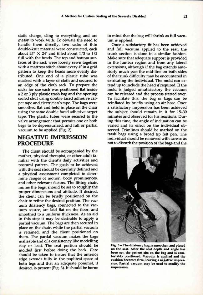
The client should be accompanied by the mother, physical therapist, or other adult familiar with the client 's daily activities and postural pattern. The goals to be achieved with the seat should be carefully defined and a physical assessment completed to determine ranges of motion, body prominences, and other relevant factors. The fitting chair, minus the bags, should be set to roughly the proper dimensions and attitude. If desired, the client can be briefly positioned on the chair to refine the desired position. The vacuum dilatency bags, connected to the vacuum source, are laid flat on the floor, and smoothed to a uniform thickness. As an aid in this step it may be desirable to apply a partial vacuum. The bags are then secured in place on the chair, while the partial vacuum is retained, and the client positioned on them. The partial vacuum makes the bags malleable and of a consistency like modelling clay or lead. The seat portion should be molded first before doing the back. Care should be taken to insure that the anterior edge extends fully in the popliteal space of both legs and that an adequate pommel , if desired, is present (Fig. 3) . It should be borne
in mind that the bag will shrink as full vacuum is applied.
Once a satisfactory fit has been achieved and full vacuum applied to the seat, the trunk section is done in a similar fashion. Make sure that adequate support is provided in the lumbar region and from any lateral extensions, al though if the bag extends anteriorly much past the mid-line on both sides of the trunk difficulty may be encountered in extricating the individual. The mold can extend up to include the head if required. If the mold is judged unsatisfactory the vacuum can be released and the process started over. To facilitate this, the bag or bags can be reinflated by briefly using an air hose. Once a satisfactory impression has been achieved the subject should remain in it for 15-30 minutes and observed for his reactions. During this t ime, the angle of inclination can be varied and its effect on the individual observed. Trimlines should be marked on the trash bags using a broad tip felt pen. The individual should be removed with care so as not to disturb the position of the bags and the
Fig. 3 —The dilatency bag is smoothen and placed on the seat. After the seat depth and angle has been set, the patient sits on the bag and is comfortably positioned. Vacuum is applied and the cushion becomes firm, leaving a negative impression. Partial vacuum may be used to modify the impression.

skin inspected for pressure areas. Measurements denoting the desired inclination should be taken from the chair and vertical reference lines marked. At no t ime can the vacuum be released without losing the impression (Fig. 4) . If the patient has a wheelchair or other wheeled base that is to be used with the finished seat, it should be measured. This concludes the evaluation and casting session, and the client can return home.
An impression is now taken of the vacuum dilatency bags using plaster-of-Paris splints. The transition zone between the two bags can be bridged with broad masking tape to provide continuity of surface and trimlines. While it adds considerably to the t ime spent on the casting process covering the entire involved surface of the two bags with masking tape creates a smoother cast. Indelible pencil should be used to make sure that all previously marked lines transfer to the splints. Once the plaster has set, the vacuum can be released and the two bags separated from the plaster-of-Paris model. The trash bags can be removed from about the cloth sacks and discarded.
FABRICATION
The plaster model should be positioned upside down on a table and the edges extended down to the table top with more splints. The interior of the model should be reinforced with a thick coating of plaster-of-Paris with rigid urethane foam (8). The plaster-of-Paris splints are left in place and not stripped off. The top surface is scraped some to smooth it, but the vast majority of the smoothing is done by adding plaster. Undesirable undercuts or protruding areas are filled. Two or three coats, smoothing with rasps and sand cloth after each, may be necessary to attain the desired results (Fig. 5). T h e model is prepared for vacuum-forming by drilling holes in the low areas, positioning it on the platen, and covering it with orlonspandex bathing suit (or leotard) material.
The seat is fabricated of three separate layers. T h e first or innermost layer is of Naugaform® 4, a vacuum-formable version of Naugahyde®. Naugaform® comes in two ver-
Fig. 4—Completed seat impression. The patient remains in the seat for 15-30 minutes to test the fit. The patient's skin is checked for pressure areas. Plaster splints are used to make a permanent impression. When a back mold is also required, masking tape may be used to bridge the gap between the seat and the back.
Fig. 5 —Positive mold ready for vacuum forming.

sions, one cloth backed and the other foam backed (no cloth reinforcement). The foam backed version is the one of choice as the absence of reinforcement means it can be formed over objects of greater surface complexity and of greater height. Foam back Naugaform® is available in limited quantities by inquiry directly to Uniroyal. It is a polymer of PVC and therefore moldable in a temperature of 350°F to 400°F . Once vacuum formed, the Naugaform® is left on the model and secured in place with staples about the periphery.
The second layer is of one inch closed-cell foam padding vacuum formed over the Naugaform®. The padding used was Enso-Foam®5, a closed-cell Polyolefin foam manufactured by Uniroyal. Enso-Foam® behaves like the various closed-cell polyethylene foams long familiar to the field of prosthetics and orthotics and is available in two densities and a range of thicknesses. The most reasonable way to fasten the two layers together is to actually do it during the process of vacuum forming the Enso-Foam®. Royal®
M6321-Contact Bond Adhesive 6 , another product of Uniroyal, is recommended for this application. The adhesive is applied to the two surfaces, the Enso-Foam® is heated, and vacuum formed over the Naugaform® and model. It may prove necessary to puncture small holes in the Naugaform® with a hypodermic needle in the various low lying areas of the model. Once the Enso-Foam® is vacuum formed it is left in place, untr immed, and the third layer is molded over it. This is of 3 /16" or 1/4" Kydex, a copolymer of acrylic and PVC. To facilitate vacuum forming the Enso-Foam should be covered with a layer of bathing suit material. Once the Kydex has cooled the seat is t r immed to approximate trimlines and is ready for temporary mounting on an interface. To finish the edges of the two interior materials, either trim the edges even and then dye the exposed Enso-Foam® surface, or leave the Naugaform® longer and roll it over the Enso-Foam. Both methods avoid permanent at tachment to the third layer of Kydex. The eventual need to dismantle the seat either in part or in total should be
Fig. 6-Finished seat mounted on plywood platform to frame for the wheeled base, also called the Universal Telescoping Interface.

kept in mind. Fastening the Enso-Foam® to the Kydex with Velcro patches allows for this.
Devising and fabricating a suitable interface to mount the seat on a wheeled base can involve considerably more time and effort than the rest of the seat put together. One method involves the use of plywood and urethane foam. Another uses metal fixtures that are attached to the seat and hook in brackets mounted on the frame of the wheeled base. A third technique employs an outer plastic shell in which the seat is placed and the void between the shell and seat filled with foam (8). A newer technique which offers particular promise involves the Universal Telescoping Interface (UTI). The UTI is an integral part of the previously described MPI system and is used to hold the seat and back portions in proper position and to mount them in a wide variety of wheeled bases. The seat and back portions of the UTI can be elongated or shortened and the angular relationship between them changed. Four metal outriggers are mounted on the frame and can be adjusted for width. The outriggers
Fig. 7A - Anterior view of the seat on the orthokinetic travel base. Small, lightweight and inexpensive wheeled bases, such as strollers or the Pogon (McClaren) buggy are satisfactory.
Fig. 7B — Lateral view. In this case, independent mobility was not a consideration.

Fig. 8A — The system the patient was previously using was large, cumbersome and heavy.
Fig. 8B — Wheelchair wheels were not necessary.
are secured to the frame of the wheeled base by metal attachment brackets. By manipulating the positions of the outriggers and brackets the position and angle of inclination of the seat can be modified. At either end of the UTI a metal bracket is secured for attachment of a foot rest and headrest. For this particular application these brackets were removed and plywood platforms secured in their place. The seat was mounted in the proper al ignment on these platforms temporarily and the void between the platform and the surface of the seat filled with rigid foam. A similar platform sitting on the frame of the UTI and under the pelvic area of the seat was devised. Once an initial fitting was performed and the orientation of the seat relative to the UTI verified, the outer surfaces of the three platforms were covered with scrap Naugaform® to present a finished appearance (Fig. 6).
Selection of an appropriate wheeled base may be constrained by the need or desire to use what the individual already has (Fig. 7a,b). If it should prove appropriate to select

Fig. 9 —The new seating system is light, less bulky and has a more pleasing appearance than the system previously used.
a new wheeled base every consideration should be given to obtaining one that is as small, l ightweight, and inexpensive as possible. In particular, it should be kept in mind that such alternatives to wheelchairs as the Pogon (McClaren) buggy and strollers have proven quite satisfactory (Fig. 8a,b).
FITTING AND FINISHING It should be anticipated that two fitting
sessions following the casting session will be necessary. The first fitting is to verify details of fit and al ignment and plan any changes. A second session is then required to check the accuracy of any changes made and to deliver the completed seat to the individual (Fig. 9). Followup either in person or by telephone with the responsible clinician involved with the patient should be conducted in about six weeks.
CONCLUSION In conclusion, a method has been de
scribed for providing custom molded seats. It
should be readily apparent that very little, if any, of the method is original, but is rather a synthesis of various methods used by others. It should also be apparent that the method is neither simple, inexpensive, nor quick. Therefore, it is felt that this method should be reserved for those individuals so severely involved that it is the most reasonable solution to a very difficult problem. For those individuals with greater flexibility and less deformity, considerably less complicated solutions to their seating needs can be devised, such as solid seats and backs, the MPI , or spinal orthoses. It should also be borne in mind that the use of such a seating technique with limited padding may be inadvisable for those with spinal cord injury due to the lack of sensation and the potential of decubitus ulcers.
References
1. E. Trefler, P. Huggins, D, Hobson, S. Hanks, S. Chiarizzio, "A Modular Seating System for Physically Handicapped Children," Proceedings of the Fourth Annual Conference on Systems and Devices for the Disabled, Univesity of Washington, Seattle, Washington, 1977, pp. 41-43.
2. E. Trefler, S. Hanks, P. Huggins, S. Chiarizzio, D. Hobson, "A Modular Seating System for Cerebral-Palsied Children," Developmental Medicine and Child Neurology, 1978, 20, 199-204
3. E. Trefler, R. Tooms, D. Hobson, "Seating for Cerebral-Palsied Children," Inter-Clinic Information Bulletin. Vol. XVII, No. 1, pp. 1-8, Jan.-Feb., 1978.
4. D. Hobson, K. Driver, S. Hanks, "Foam-In-Place Seating for the Severely Disabled, Preliminary Results," Proceedings of the Fifth Annual Conference on Systems and Devices for the Disabled, Houston, Texas, 1978, pp. 153-136.
5. M. Forbes, R. Holte, I. Paul, E. von Kamper, "A Comparison of Three Custom Seating Techniques," Proceedings of International Conference on Rehabilitation Engineering, Toronto, 1980, pp. 147-152,
6. J. Carlson, R. Winter, "The 'Gillette' Sitting Orthosis," Orthotics and Prosthetics, Vol. 32, No. 4, pp. 35-45, Dec. 1978
7. J. Bowker, B. Reed. "A Vacuum Formed Plastic Insert Seat for Neurologically Handicapped Wheelchair Patients," Inter-Clinic Information Bulletin, 12(10), 7-17, July, 1973
8. D. May, R. Fincke, L. Cancelliere, J. Bretz, S. Gallo, "Individually Customized Postural Support System," Proceedings of International Conference on Rehabilitation Engineering, Toronto, 1980, pp. 144-146.
9. J. O'Reagan, D. Law. "Usable Reusable Casting Technique for Customized Total Contact Seating," Proceedings of International Conference on Rehabilitation Engineering, Toronto, 1980, pp. 153-155.
Footnotes
1Formerly Director, Prosthetics and Orthotics Laboratory, Rehabilitation Engineering Center # 2 , Moss Rehabilitation Hospital, 12th Street and Tabor Road, Philadelphia, Pa. 19141. Presently, manager, Snells of Louisville, 744 E. Broadview, Louisville, Ky 40202.
2Research Physical Therapist, Rehabilitation Engineering Center # 2 , Moss Rehabilitation Hospital, 12th Street and Tabor Road, Philadelphia, Pa. 19141.
3Medical Equipment Distributors, Inc., 1701 S. First Street, Maywood, III. 60153.
4Uniroyal, Inc., Coated Fabric and Foam Specialties Department, 312 N., Hill Street, Mishawaka, Ind. 46544.
5Uniroyal, Inc., Expanded Products Department, Mishawaka, Ind. 46544. 6Uniroyal, Inc., Adhesives and Sealants Department, Mishawaka, Ind.
46544