a low cost 3d-measurement tool for … · a low cost 3d-measurement tool for architectural and...
TRANSCRIPT
A LOW COST 3D-MEASUREMENT TOOL FOR ARCHITECTURAL AND ARCHAEOLOGICAL APPLICATIONS
Klaus Hanke, Associate Professor Institute of Geodesy, University of Innsbruck, Austria
Mostafa Abdel-Bary Ebrahim, M. Sc.
Assiut University, Egypt, Doctoral Student at Innsbruck University, Austria
KEY WORDS: Accuracy, Architectural photogrammetry, Archaeological surveying, PhotoModeler. ABSTRACT: An important question to be answered for any measurement tool is ” How accurate is it ?”. Because of this question, an accuracy investigation has been done to obtain the accuracy of a low cost tool of measurements for the architectural and archaeological applications. The aim of this investigation is to study the accuracy of a low cost photogrammetric softcopy close-range program ”PhotoModeler” developed and distributed by Eos Systems, Vancouver, Canada. The software contains a bundle adjustment program for digital images and a camera calibration part. It is easy to use and requires only short time to familiarize with. Different types of cameras with different types of calibration of these cameras and different numbers and arrangements of photographs have been tested. A brick wall with a good contrast of its brick corners has been chosen to be a test field because it is of the same type as in many architectural and archaeological applications. To properly document the various levels of accuracy one can achieve with this program, the results have been compared with high accuracy measurements from other standard surveying methods, the accuracy of the control points lies between 1.0 and 1.5 mm absolute. Two types of cameras have been used, a common small format ”amateur camera” Ashai Pentax and a metric camera WILD P32. The non-metric camera has been calibrated in three different ways to show the effect of the lens distortion on the accuracy of the measurements. Two different camera configurations have been used for both camera types, once for top and lower camera positions and another for just lower camera positions only. The results are very promising, the achieved accuracy in the distances between measured points is in the range of 1:1700 to 1:6500 of the object’s size. Regarding to the points’ co-ordinates, the average accuracy reached up to 1:8000.
INTRODUCTION In theory of errors of measurements the term accuracy is traditionally used for a concept that measures the closeness of derived estimated or predicted data to reality. Photogrammetrists very often estimate the accuracy of a method by controlled experiments, where the photogrammetrically determined co-ordinates are compared with so called given co-ordinates that have an accuracy that is considerably higher than that of the method to be checked (Ebrahim M., 1992). An accuracy investigation has been carried out to obtain the accuracy of the 3D-models that can be expected from the PhotoModeler software for the architectural and archaeological applications. Both, a metric camera and a non-metric camera have been investigated. To obtain the accuracy of the non-metric camera, a calibration of this camera has been done using PhotoModeler's own calibrator software. Different calibration projects for the non-metric camera have been used to obtain the accuracy with different camera parameters. The first project has been done with full camera lens distortion, the second with radial lens distortion only and the third without any lens distortion parameters. Also two different configurations have been used. One with upper and lower camera positions and the other with lower positions only.
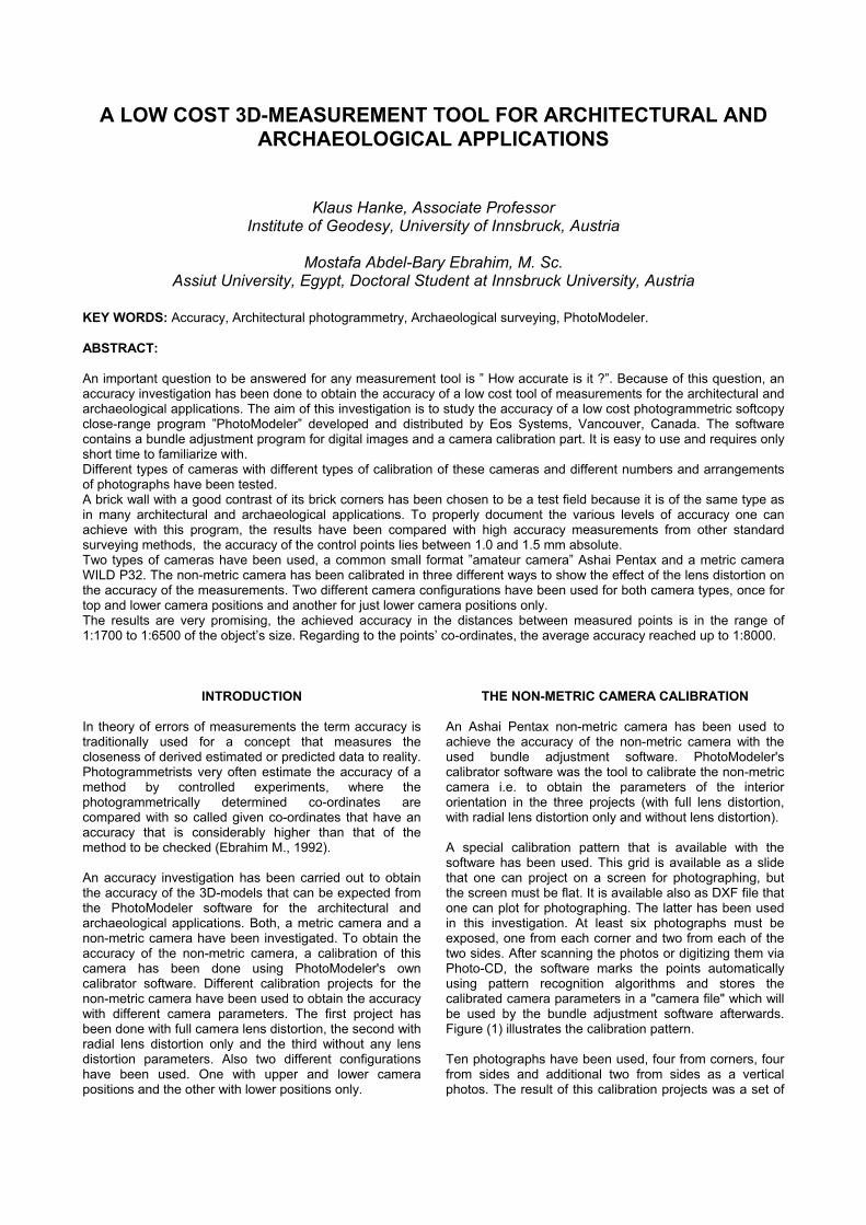
THE NON-METRIC CAMERA CALIBRATION An Ashai Pentax non-metric camera has been used to achieve the accuracy of the non-metric camera with the used bundle adjustment software. PhotoModeler's calibrator software was the tool to calibrate the non-metric camera i.e. to obtain the parameters of the interior orientation in the three projects (with full lens distortion, with radial lens distortion only and without lens distortion). A special calibration pattern that is available with the software has been used. This grid is available as a slide that one can project on a screen for photographing, but the screen must be flat. It is available also as DXF file that one can plot for photographing. The latter has been used in this investigation. At least six photographs must be exposed, one from each corner and two from each of the two sides. After scanning the photos or digitizing them via Photo-CD, the software marks the points automatically using pattern recognition algorithms and stores the calibrated camera parameters in a "camera file" which will be used by the bundle adjustment software afterwards. Figure (1) illustrates the calibration pattern. Ten photographs have been used, four from corners, four from sides and additional two from sides as a vertical photos. The result of this calibration projects was a set of
camera parameters for each of the cases mentioned above.
Fig. (1) The calibration pattern
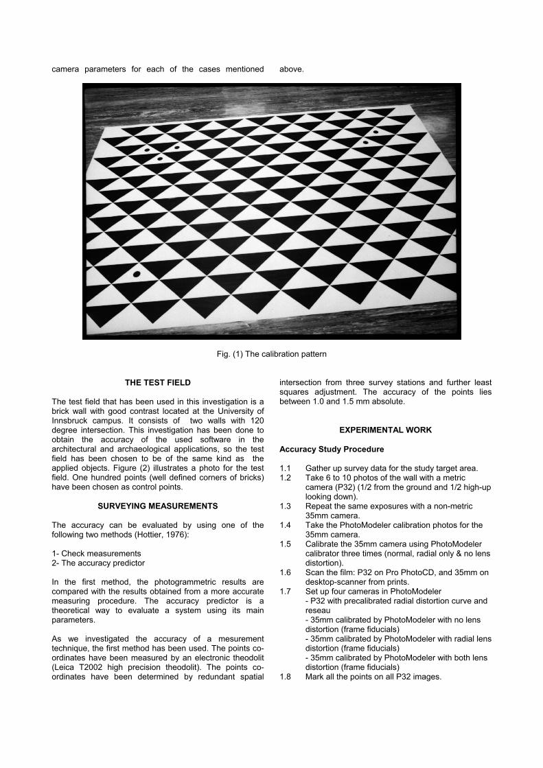
THE TEST FIELD The test field that has been used in this investigation is a brick wall with good contrast located at the University of Innsbruck campus. It consists of two walls with 120 degree intersection. This investigation has been done to obtain the accuracy of the used software in the architectural and archaeological applications, so the test field has been chosen to be of the same kind as the applied objects. Figure (2) illustrates a photo for the test field. One hundred points (well defined corners of bricks) have been chosen as control points.
SURVEYING MEASUREMENTS
The accuracy can be evaluated by using one of the following two methods (Hottier, 1976): 1- Check measurements 2- The accuracy predictor In the first method, the photogrammetric results are compared with the results obtained from a more accurate measuring procedure. The accuracy predictor is a theoretical way to evaluate a system using its main parameters. As we investigated the accuracy of a mesurement technique, the first method has been used. The points co-ordinates have been measured by an electronic theodolit (Leica T2002 high precision theodolit). The points co-ordinates have been determined by redundant spatial
intersection from three survey stations and further least squares adjustment. The accuracy of the points lies between 1.0 and 1.5 mm absolute.
EXPERIMENTAL WORK
Accuracy Study Procedure 1.1 Gather up survey data for the study target area. 1.2 Take 6 to 10 photos of the wall with a metric
camera (P32) (1/2 from the ground and 1/2 high-up looking down).
1.3 Repeat the same exposures with a non-metric 35mm camera.
1.4 Take the PhotoModeler calibration photos for the 35mm camera.
1.5 Calibrate the 35mm camera using PhotoModeler calibrator three times (normal, radial only & no lens distortion).
1.6 Scan the film: P32 on Pro PhotoCD, and 35mm on desktop-scanner from prints.
1.7 Set up four cameras in PhotoModeler - P32 with precalibrated radial distortion curve and reseau - 35mm calibrated by PhotoModeler with no lens distortion (frame fiducials) - 35mm calibrated by PhotoModeler with radial lens distortion (frame fiducials) - 35mm calibrated by PhotoModeler with both lens distortion (frame fiducials)
1.8 Mark all the points on all P32 images.
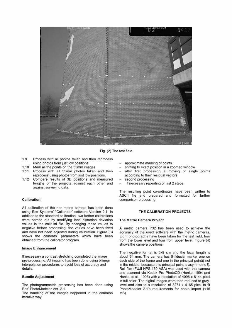
Fig. (2) The test field 1.9 Process with all photos taken and then reprocess
using photos from just low positions. 1.10 Mark all the points on the 35mm images. 1.11 Process with all 35mm photos taken and then
reprocess using photos from just low positions. 1.12 Compare results of 3D positions and measured
lengths of the projects against each other and against surveying data.
Calibration All calibration of the non-metric camera has been done using Eos Systems’ ”Calibrator” software Version 2.1. In addition to the standard calibration, two further calibrations were carried out by modifying lens distortion deviation values in the calib.ini file. By changing these values to negative before processing, the values have been fixed and have not been adjusted during calibration. Figure (3) shows the cameras’ parameters which have been obtained from the calibrator program. Image Enhancement If necessary a contrast stretching completed the image pre-processing. All imaging has been done using bilinear interpolation procedures to avoid loss of accuracy and details. Bundle Adjustment The photogrammetric processing has been done using Eos’ PhotoModeler Ver. 2.1. The handling of the images happened in the common iterative way:
- approximate marking of points - shifting to exact position in a zoomed window - after first processing a moving of single points
according to their residual vectors - second processing - if necessary repeating of last 2 steps. The resulting point co-ordinates have been written to ASCII file and prepared and formatted for further comparison processing.
THE CALIBRATION PROJECTS
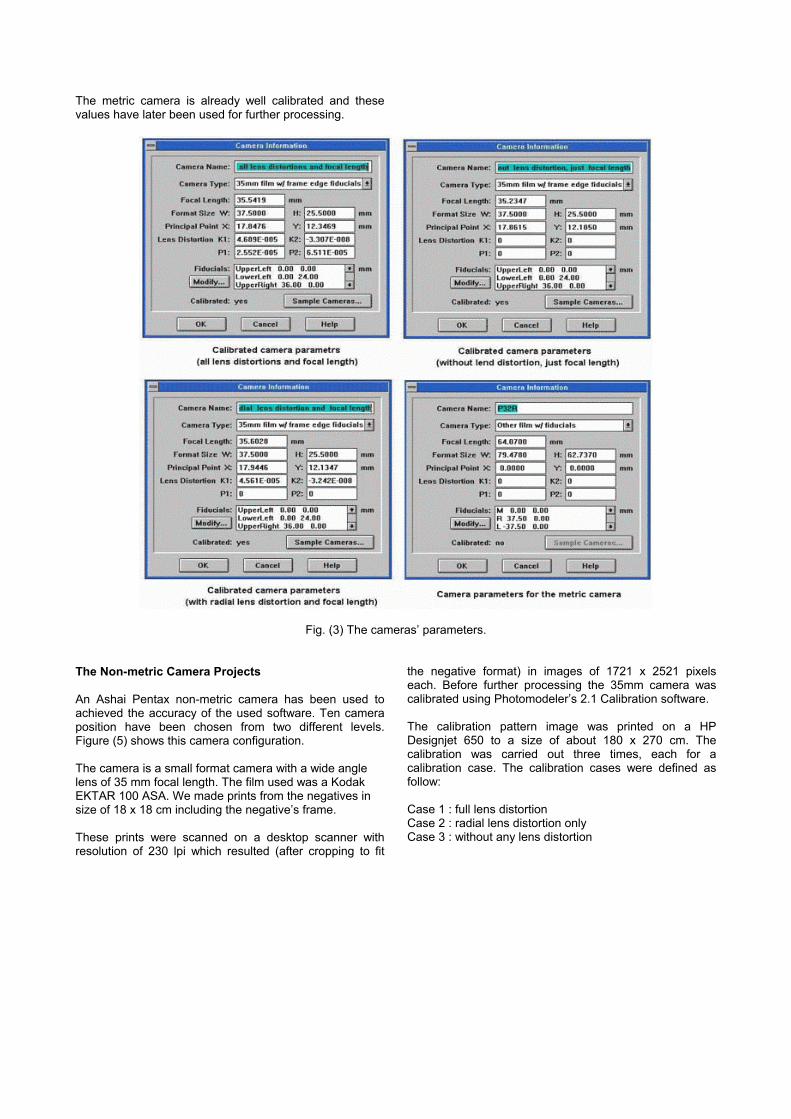
The Metric Camera Project A metric camera P32 has been used to achieve the accuracy of the used software with the metric cameras. Eight photographs have been taken for the test field, four from the lower level and four from upper level. Figure (4) shows the camera positions. The negative format is 6x9 cm and the focal length is about 64 mm. The camera has 5 fiducial marks( one on each side of the frame and one in the principal point)( not in the middle, because this principal point is asymmetric !). Roll film (FUJI NPS 160 ASA) was used with this camera and scanned via Kodak Pro PhotoCD (Hanke, 1994 and Hanke et al., 1995) with a resolution of 4096 x 6144 pixel in full color. The digital images were then reduced to gray-level and also to a resolution of 3271 x 4165 pixel to fit PhotoModeler 2.1’s requirements for photo import (<16 MB).
The metric camera is already well calibrated and these values have later been used for further processing.
Fig. (3) The cameras’ parameters.
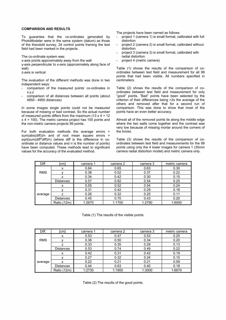
The Non-metric Camera Projects An Ashai Pentax non-metric camera has been used to achieved the accuracy of the used software. Ten camera position have been chosen from two different levels. Figure (5) shows this camera configuration. The camera is a small format camera with a wide angle lens of 35 mm focal length. The film used was a Kodak EKTAR 100 ASA. We made prints from the negatives in size of 18 x 18 cm including the negative’s frame. These prints were scanned on a desktop scanner with resolution of 230 lpi which resulted (after cropping to fit
the negative format) in images of 1721 x 2521 pixels each. Before further processing the 35mm camera was calibrated using Photomodeler’s 2.1 Calibration software. The calibration pattern image was printed on a HP Designjet 650 to a size of about 180 x 270 cm. The calibration was carried out three times, each for a calibration case. The calibration cases were defined as follow: Case 1 : full lens distortion Case 2 : radial lens distortion only Case 3 : without any lens distortion
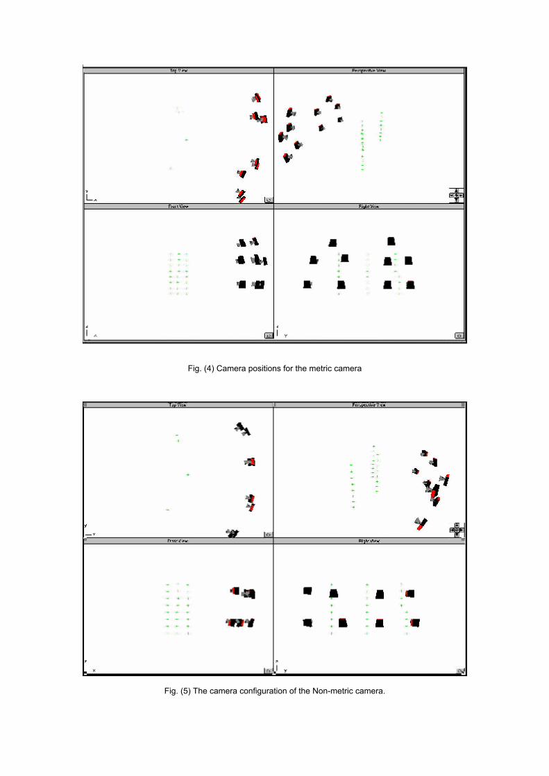
Fig. (4) Camera positions for the metric camera
Fig. (5) The camera configuration of the Non-metric camera.
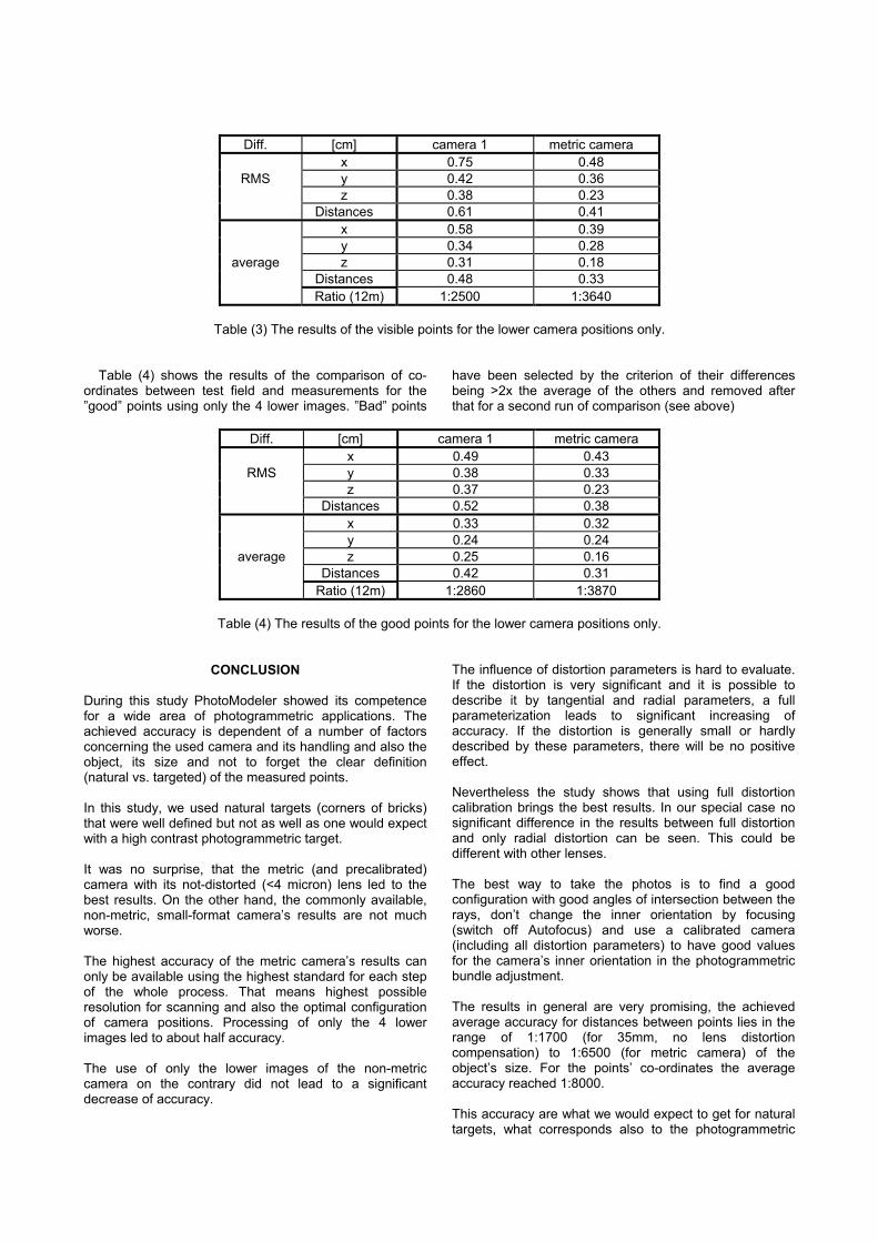
COMPARISON AND RESULTS To guarantee that the co-ordinates generated by PhotoModeler were in the same system (datum) as those of the theodolit survey, 24 control points framing the test field had been marked in the projects. The co-ordinate system was: x-axis points approximately away from the wall y-axis perpendicular to x-axis (approximately along face of wall) z-axis is vertical The evaluation of the different methods was done in two independent ways: - comparison of the measured points’ co-ordinates in
x,y,z - comparison of all distances between all points (about
4850 - 4950 distances) In some images single points could not be measured because of missing or bad contrast. So the actual number of measured points differs from the maximum (13 x 4 + 12 x 4 = 100). The metric camera project has 100 points and the non-metric camera projects 99 points. For both evaluation methods the average errors = sum(abs(diff))/n and of root mean square errors = sqrt(sum(diff*diff)/n) (where diff is the difference in co-ordinate or distance values and n is the number of points) have been computed. These methods lead to significant values for the accuracy of the evaluated method.
The projects have been named as follows: - project 1 (camera 1) is small format, calibrated with full
distortion - project 2 (camera 2) is small format, calibrated without
distortion - project 3 (camera 3) is small format, calibrated with
radial distortion - project 4 (metric camera) Table (1) shows the results of the comparison of co-ordinates between test field and measurement for all 99 points that had been visible. All numbers specified in centimeters. Table (2) shows the results of the comparison of co-ordinates between test field and measurement for only ”good” points. ”Bad” points have been selected by the criterion of their differences being >2x the average of the others and removed after that for a second run of comparison. This was done to show that most of the points have an even better accuracy. Almost all of the removed points lie along the middle edge where the two walls come together and the contrast was very low because of missing mortar around the corners of the bricks. Table (3) shows the results of the comparison of co-ordinates between test field and measurements for the 99 points using only the 4 lower images for camera 1 (35mm camera radial distortion model) and metric camera only.
Diff. [cm] camera 1 camera 2 camera 3 metric camera x 0.64 0.65 0.63 0.30
RMS y 0.38 0.52 0.37 0.22 z 0.34 0.42 0.30 0.15 Distances 0.57 0.82 0.54 0.25 x 0.55 0.52 0.54 0.24 y 0.31 0.42 0.29 0.18
average z 0.26 0.32 0.25 0.11 Distances 0.45 0.70 0.43 0.20 Ratio (12m) 1:2670 1:1700 1:2790 1:6000
Table (1) The results of the visible points.
Diff. [cm] camera 1 camera 2 camera 3 metric camera x 0.53 0.47 0.53 0.25
RMS y 0.36 0.50 0.34 0.20 z 0.33 0.35 0.29 0.13 Distances 0.53 0.74 0.49 0.22 x 0.42 0.31 0.42 0.19 y 0.27 0.32 0.24 0.15
average z 0.22 0.21 0.21 0.09 Distances 0.44 0.63 0.40 0.18 Ratio (12m) 1:2730 1:1900 1:3000 1:6670
Table (2) The results of the good points.
Diff. [cm] camera 1 metric camera x 0.75 0.48
RMS y 0.42 0.36 z 0.38 0.23 Distances 0.61 0.41 x 0.58 0.39 y 0.34 0.28
average z 0.31 0.18 Distances 0.48 0.33 Ratio (12m) 1:2500 1:3640
Table (3) The results of the visible points for the lower camera positions only.
Table (4) shows the results of the comparison of co-ordinates between test field and measurements for the ”good” points using only the 4 lower images. ”Bad” points
have been selected by the criterion of their differences being >2x the average of the others and removed after that for a second run of comparison (see above)
Diff. [cm] camera 1 metric camera
x 0.49 0.43 RMS y 0.38 0.33
z 0.37 0.23 Distances 0.52 0.38 x 0.33 0.32 y 0.24 0.24
average z 0.25 0.16 Distances 0.42 0.31 Ratio (12m) 1:2860 1:3870
Table (4) The results of the good points for the lower camera positions only.
CONCLUSION During this study PhotoModeler showed its competence for a wide area of photogrammetric applications. The achieved accuracy is dependent of a number of factors concerning the used camera and its handling and also the object, its size and not to forget the clear definition (natural vs. targeted) of the measured points. In this study, we used natural targets (corners of bricks) that were well defined but not as well as one would expect with a high contrast photogrammetric target. It was no surprise, that the metric (and precalibrated) camera with its not-distorted (<4 micron) lens led to the best results. On the other hand, the commonly available, non-metric, small-format camera’s results are not much worse. The highest accuracy of the metric camera’s results can only be available using the highest standard for each step of the whole process. That means highest possible resolution for scanning and also the optimal configuration of camera positions. Processing of only the 4 lower images led to about half accuracy. The use of only the lower images of the non-metric camera on the contrary did not lead to a significant decrease of accuracy.
The influence of distortion parameters is hard to evaluate. If the distortion is very significant and it is possible to describe it by tangential and radial parameters, a full parameterization leads to significant increasing of accuracy. If the distortion is generally small or hardly described by these parameters, there will be no positive effect. Nevertheless the study shows that using full distortion calibration brings the best results. In our special case no significant difference in the results between full distortion and only radial distortion can be seen. This could be different with other lenses. The best way to take the photos is to find a good configuration with good angles of intersection between the rays, don’t change the inner orientation by focusing (switch off Autofocus) and use a calibrated camera (including all distortion parameters) to have good values for the camera’s inner orientation in the photogrammetric bundle adjustment. The results in general are very promising, the achieved average accuracy for distances between points lies in the range of 1:1700 (for 35mm, no lens distortion compensation) to 1:6500 (for metric camera) of the object’s size. For the points’ co-ordinates the average accuracy reached 1:8000. This accuracy are what we would expect to get for natural targets, what corresponds also to the photogrammetric
theory and what meets the requirements for e.g. architectural applications.
BIBLIOGRAPHY AND REFERENCES Ebrahim M. A-B., 1992 Using close range photogrammetry for some engineering applications M.Sc. thesis, University of Assiut, Egypt, March. Hanke, K. 1994 ”The Photo CD - A Source and Digital Memory for Photogrammetric Images.” Intercongress-Symposium of ISPRS-Commission V, Melbourne, Australia. In: International Archives of Photogrammetry and Remote Sensing, Volume XXX, Part 5
Hanke, K., Weinold, Th. 1995 ”Using the Photo CD as a Source and Digital Memory for Photogrammetric Images - A Report on its Data Compression Method and the Geometrical Stability of the Transferred Images.” Proceedings of the St.Petersburg - Great Lakes - Conference Digital Imaging and Remote Sensing 95, 25. - 30. June 1995, St.Petersburg, Russia, GUS. SPIE-Publications, Series P, Vol. 2646, Washington DC , USA Hottier Ph., 1976
Accuracy of close range analytical restitution: practical experiments and prediction Photogrammetric engineering and remote sensing, 42(3). Karara H.M. and Abdel-Aziz Y.I. 1974 Accuracy aspects of non-metric imageries Photogrammetric engineering and remote sensing 52,(8). Mahajan S.K. and Singh V., 1972 Comparison of analytical relative orientation methods Journal of the surveying and mapping division, July. Mahani R.B., 1981 Close range photogrammetry practical applications and development of a multi-station-stereo system Ph.D. thesis, University of Manchester, April. Mohamed A.A., Abdel-Aal A-A. M., and Ebrahim M. A-B., 1994 A study on the factors affecting the accuracy in close range photogrammetry Journal of Helwan University, Engng. Res. Bull., Vol. 2, April. Murai S., Nakamura H. and Suzuki Y., 1980 Analytical orientation for non-metric camera in the application to terrestrial photogrammetry 4th ISPRS congress, Hamburg, Commission V, work group 5.