a. lofted surface guide curve sketch1. - cudacountry 15 deck skateboard page 1-1 skateboard deck a....
TRANSCRIPT
SOLIDWORKS 15 DecK SKATeBOARD PAge 1-1
Skateboard
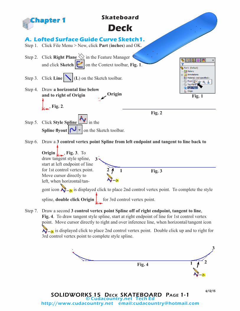
Deck A. Lofted Surface Guide Curve Sketch1. Step 1. Click File Menu > New, click Part (inches) and OK.
Step 2. Click Right Plane in the Feature Managerand click Sketch on the Context toolbar, Fig. 1.
Step 3. Click Line (L) on the Sketch toolbar.
Step 4. Draw a horizontal line belowand to right of Origin
, Fig. 2.
Step 5. Click Style Spline in the
Spline flyout on the Sketch toolbar.
Step 6. Draw a 3 control vertex point Spline from left endpoint and tangent to line back to
Origin , Fig. 3. To draw tangent style spline, start at left endpoint of line for 1st control vertex point. Move cursor directly to left, when horizontal/tan-
gent icon is displayed click to place 2nd control vertex point. To complete the style
spline, double click Origin for 3rd control vertex point.
Step 7. Draw a second 3 control vertex point Spline off of right endpoint, tangent to line,Fig. 4. To draw tangent style spline, start at right endpoint of line for 1st control vertex point. Move cursor directly to right and over inference line, when horizontal/tangent icon
is displayed click to place 2nd control vertex point. Double click up and to right for 3rd control vertex point to complete style spline.
Chapter 1
Origin
6/12/15
Fig. 1
Fig. 2
Fig. 3
Fig. 4
12
3
1 2
3
© Cudacountry.net Tech Edhttp://www.cudacountry.net email:[email protected]
SOLIDWORKS 15 DecK SKATeBOARD PAge 1-2
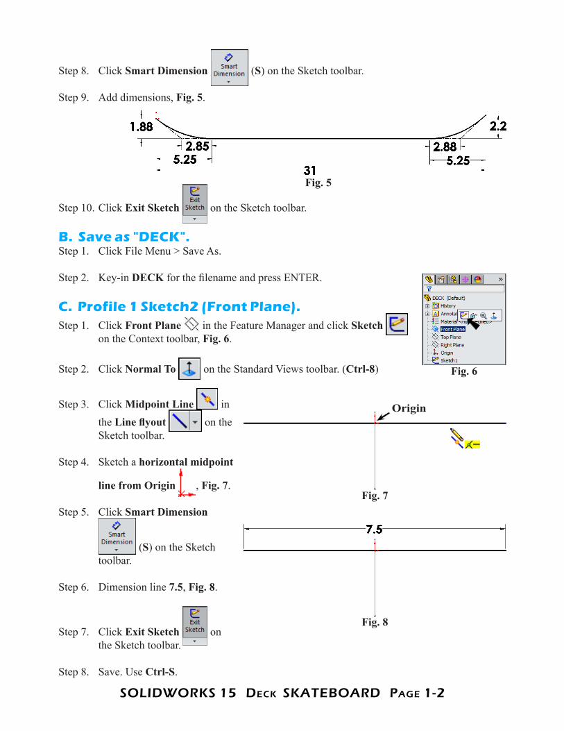
Step 8. Click Smart Dimension (S) on the Sketch toolbar.
Step 9. Add dimensions, Fig. 5.
Step 10. Click Exit Sketch on the Sketch toolbar.
B. Save as "DECK".Step 1. Click File Menu > Save As.
Step 2. Key-in DECK for the filename and press ENTER.
C. Profile 1 Sketch2 (Front Plane).Step 1. Click Front Plane in the Feature Manager and click Sketch
on the Context toolbar, Fig. 6.
Step 2. Click Normal To on the Standard Views toolbar. (Ctrl-8)
Step 3. Click Midpoint Line in the Line flyout on the Sketch toolbar.
Step 4. Sketch a horizontal midpoint
line from Origin , Fig. 7.
Step 5. Click Smart Dimension
(S) on the Sketch toolbar.
Step 6. Dimension line 7.5, Fig. 8.
Step 7. Click Exit Sketch on the Sketch toolbar.
Step 8. Save. Use Ctrl-S.
Fig. 5
Fig. 6
Origin
Fig. 7
Fig. 8
SOLIDWORKS 15 DecK SKATeBOARD PAge 1-3
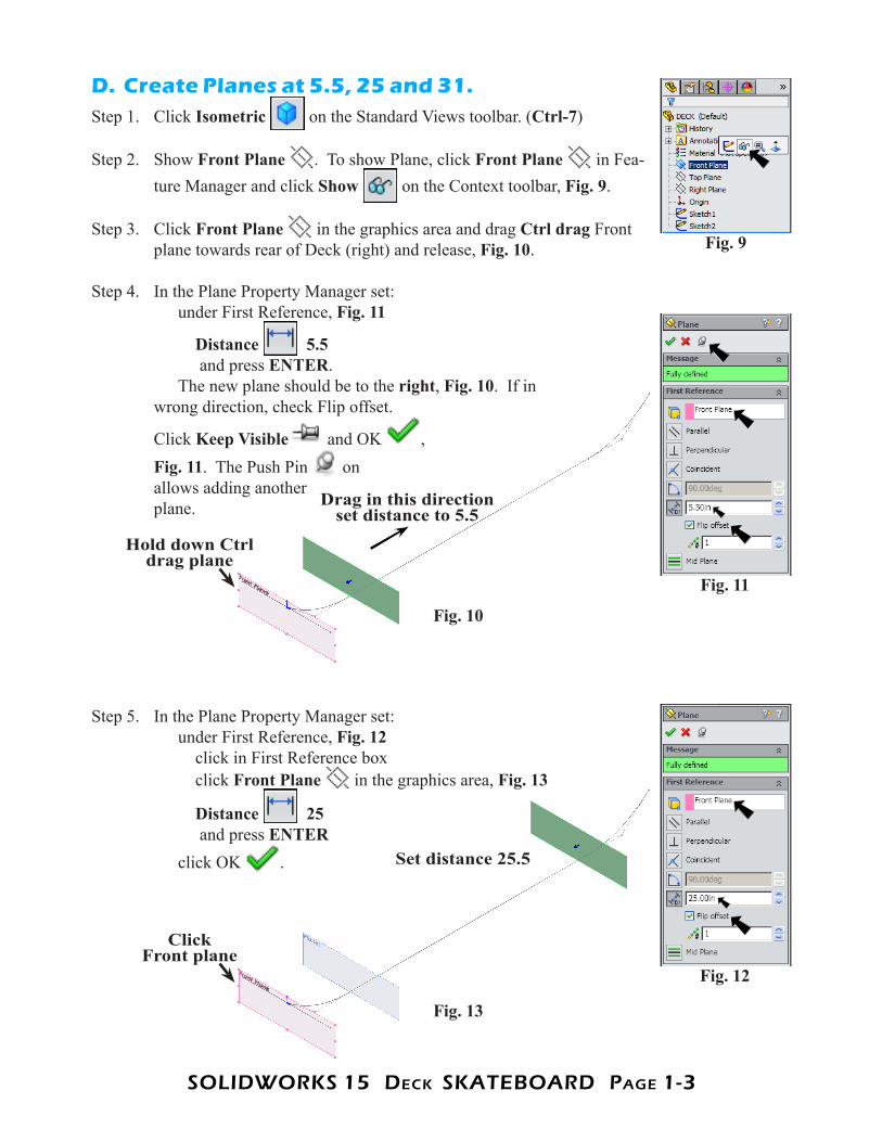
D. Create Planes at 5.5, 25 and 31.Step 1. Click Isometric on the Standard Views toolbar. (Ctrl-7)
Step 2. Show Front Plane . To show Plane, click Front Plane in Fea-ture Manager and click Show on the Context toolbar, Fig. 9.
Step 3. Click Front Plane in the graphics area and drag Ctrl drag Front plane towards rear of Deck (right) and release, Fig. 10.
Step 4. In the Plane Property Manager set: under First Reference, Fig. 11
Distance 5.5 and press ENTER. The new plane should be to the right, Fig. 10. If in wrong direction, check Flip offset.
Click Keep Visible and OK , Fig. 11. The Push Pin onallows adding another plane.
Step 5. In the Plane Property Manager set: under First Reference, Fig. 12 click in First Reference box click Front Plane in the graphics area, Fig. 13
Distance 25 and press ENTER click OK .
Fig. 9
Fig. 11
Fig. 12
Fig. 10
Hold down Ctrl drag plane
Drag in this direction
set distance to 5.5
Fig. 13
Click Front plane
Set distance 25.5
SOLIDWORKS 15 DecK SKATeBOARD PAge 1-4
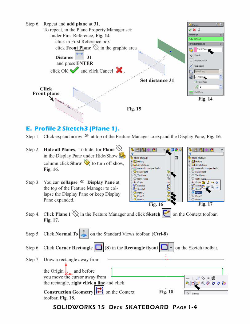
Step 6. Repeat and add plane at 31.To repeat, in the Plane Property Manager set: under First Reference, Fig. 14 click in First Reference box click Front Plane in the graphic area
Distance 31 and press ENTER click OK and click Cancel .
E. Profile 2 Sketch3 (Plane 1).Step 1. Click expand arrow at top of the Feature Manager to expand the Display Pane, Fig. 16.
Step 2. Hide all Planes. To hide, for Plane in the Display Pane under Hide/Show column click Show to turn off show, Fig. 16.
Step 3. You can collapse Display Pane at the top of the Feature Manager to col-lapse the Display Pane or keep Display Pane expanded.
Step 4. Click Plane 1 in the Feature Manager and click Sketch on the Context toolbar, Fig. 17.
Step 5. Click Normal To on the Standard Views toolbar. (Ctrl-8)
Step 6. Click Corner Rectangle (S) in the Rectangle flyout on the Sketch toolbar.
Step 7. Draw a rectangle away from
the Origin and before you move the cursor away from the rectangle, right click a line and click
Construction Geometry on the Context toolbar, Fig. 18.
Fig. 14
Fig. 15
Set distance 31
Fig. 16 Fig. 17
Fig. 18
Click Front plane
SOLIDWORKS 15 DecK SKATeBOARD PAge 1-5
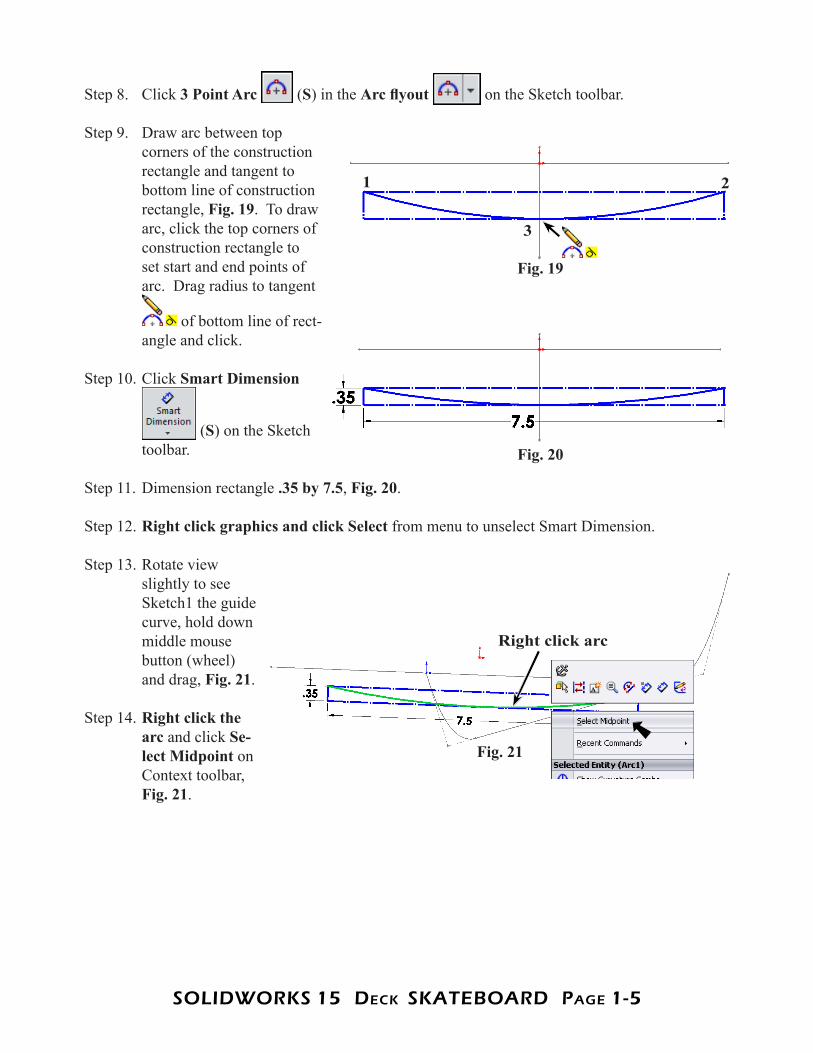
Step 8. Click 3 Point Arc (S) in the Arc flyout on the Sketch toolbar.
Step 9. Draw arc between top corners of the construction rectangle and tangent to bottom line of construction rectangle, Fig. 19. To draw arc, click the top corners of construction rectangle to set start and end points of arc. Drag radius to tangent
of bottom line of rect-angle and click.
Step 10. Click Smart Dimension
(S) on the Sketch toolbar.
Step 11. Dimension rectangle .35 by 7.5, Fig. 20.
Step 12. Right click graphics and click Select from menu to unselect Smart Dimension.
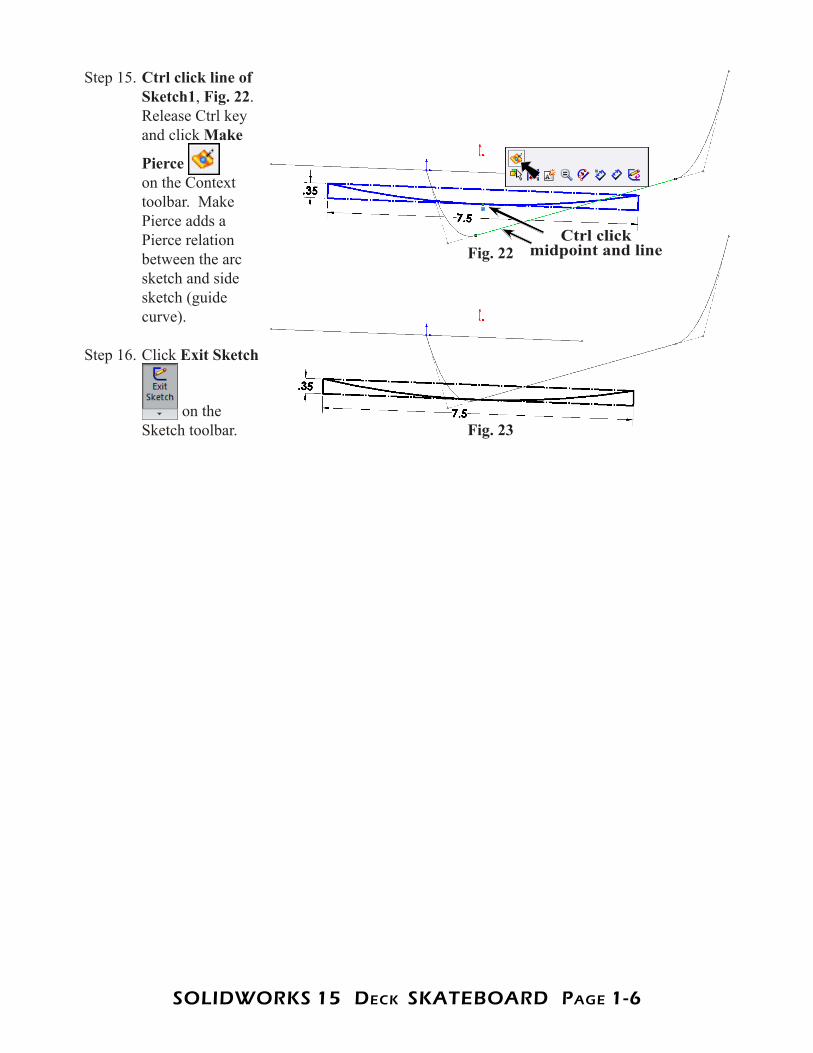
Step 13. Rotate view slightly to see Sketch1 the guide curve, hold down middle mouse button (wheel) and drag, Fig. 21.
Step 14. Right click the arc and click Se-lect Midpoint on Context toolbar, Fig. 21.
Fig. 19
Fig. 20
Fig. 21
Right click arc
1 2
3
SOLIDWORKS 15 DecK SKATeBOARD PAge 1-6
Step 15. Ctrl click line of Sketch1, Fig. 22. Release Ctrl key and click Make
Pierce on the Context toolbar. Make Pierce adds a Pierce relation between the arc sketch and side sketch (guide curve).
Step 16. Click Exit Sketch
on the Sketch toolbar. Fig. 23
Fig. 22Ctrl click
midpoint and line
SOLIDWORKS 15 DecK SKATeBOARD PAge 1-7
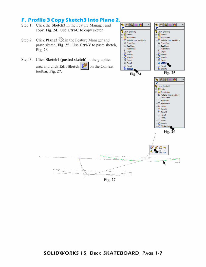
F. Profile 3 Copy Sketch3 into Plane 2.Step 1. Click the Sketch3 in the Feature Manager and
copy, Fig. 24. Use Ctrl-C to copy sketch.
Step 2. Click Plane2 in the Feature Manager and paste sketch, Fig. 25. Use Ctrl-V to paste sketch, Fig. 26.
Step 3. Click Sketch4 (pasted sketch) in the graphics
area and click Edit Sketch on the Context toolbar, Fig. 27. Fig. 25Fig. 24
Fig. 26
Fig. 27
SOLIDWORKS 15 DecK SKATeBOARD PAge 1-8
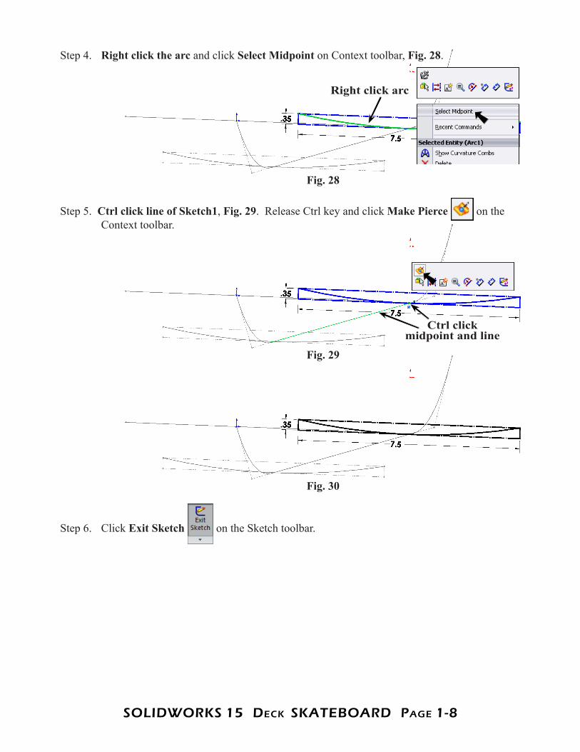
Step 4. Right click the arc and click Select Midpoint on Context toolbar, Fig. 28.
Step 5. Ctrl click line of Sketch1, Fig. 29. Release Ctrl key and click Make Pierce on the Context toolbar.
Step 6. Click Exit Sketch on the Sketch toolbar.
Fig. 28
Fig. 30
Fig. 29
Right click arc
Ctrl click midpoint and line
SOLIDWORKS 15 DecK SKATeBOARD PAge 1-9
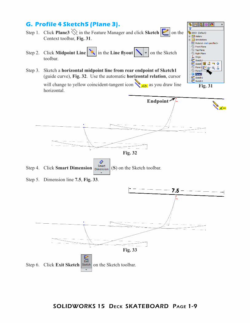
G. Profile 4 Sketch5 (Plane 3).Step 1. Click Plane3 in the Feature Manager and click Sketch on the
Context toolbar, Fig. 31.
Step 2. Click Midpoint Line in the Line flyout on the Sketch toolbar.
Step 3. Sketch a horizontal midpoint line from rear endpoint of Sketch1 (guide curve), Fig. 32. Use the automatic horizontal relation, cursor
will change to yellow coincident-tangent icon as you draw line horizontal.
Step 4. Click Smart Dimension (S) on the Sketch toolbar.
Step 5. Dimension line 7.5, Fig. 33.
Step 6. Click Exit Sketch on the Sketch toolbar.
Fig. 31
Fig. 32
Endpoint
Fig. 33
SOLIDWORKS 15 DecK SKATeBOARD PAge 1-10
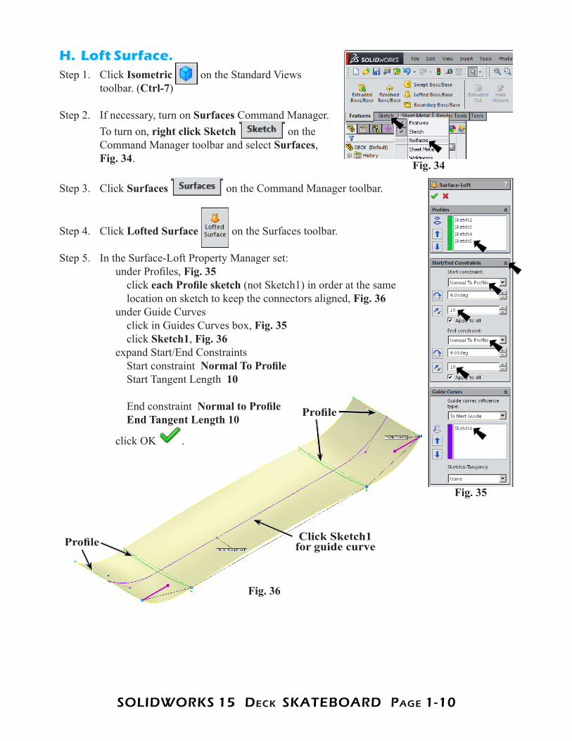
H. Loft Surface.Step 1. Click Isometric on the Standard Views
toolbar. (Ctrl-7)
Step 2. If necessary, turn on Surfaces Command Manager. To turn on, right click Sketch on the Command Manager toolbar and select Surfaces, Fig. 34.
Step 3. Click Surfaces on the Command Manager toolbar.
Step 4. Click Lofted Surface on the Surfaces toolbar.
Step 5. In the Surface-Loft Property Manager set: under Profiles, Fig. 35 click each Profile sketch (not Sketch1) in order at the same location on sketch to keep the connectors aligned, Fig. 36 under Guide Curves click in Guides Curves box, Fig. 35 click Sketch1, Fig. 36 expand Start/End Constraints Start constraint Normal To Profile Start Tangent Length 10 End constraint Normal to Profile End Tangent Length 10
click OK .
Fig. 34
Fig. 36
Click Sketch1 for guide curve
Fig. 35
Profile
Profile
SOLIDWORKS 15 DecK SKATeBOARD PAge 1-11
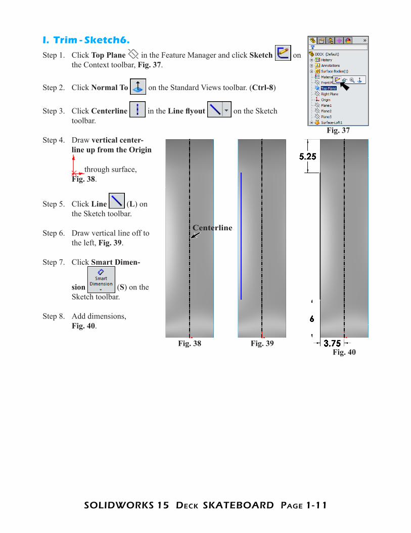
I. Trim - Sketch6.Step 1. Click Top Plane in the Feature Manager and click Sketch on
the Context toolbar, Fig. 37.
Step 2. Click Normal To on the Standard Views toolbar. (Ctrl-8)
Step 3. Click Centerline in the Line flyout on the Sketch toolbar.
Step 4. Draw vertical center-line up from the Origin
through surface,Fig. 38.
Step 5. Click Line (L) on the Sketch toolbar.
Step 6. Draw vertical line off to the left, Fig. 39.
Step 7. Click Smart Dimen-
sion (S) on the Sketch toolbar.
Step 8. Add dimensions, Fig. 40.
Fig. 37
Fig. 40Fig. 39Fig. 38
Centerline
SOLIDWORKS 15 DecK SKATeBOARD PAge 1-12
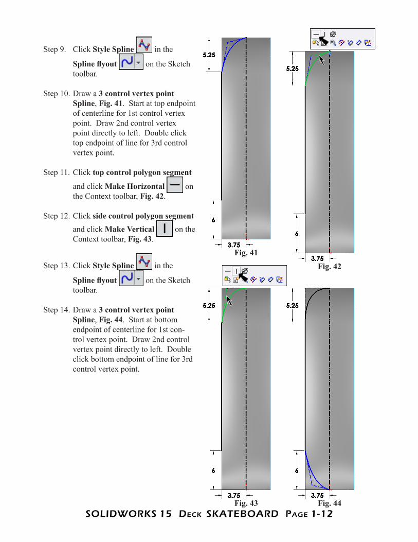
Step 9. Click Style Spline in the
Spline flyout on the Sketch toolbar.
Step 10. Draw a 3 control vertex point Spline, Fig. 41. Start at top endpoint of centerline for 1st control vertex point. Draw 2nd control vertex point directly to left. Double click top endpoint of line for 3rd control vertex point.
Step 11. Click top control polygon segment
and click Make Horizontal on the Context toolbar, Fig. 42.
Step 12. Click side control polygon segment and click Make Vertical on the Context toolbar, Fig. 43.
Step 13. Click Style Spline in the
Spline flyout on the Sketch toolbar.
Step 14. Draw a 3 control vertex point Spline, Fig. 44. Start at bottom endpoint of centerline for 1st con-trol vertex point. Draw 2nd control vertex point directly to left. Double click bottom endpoint of line for 3rd control vertex point.
Fig. 42
Fig. 41
Fig. 44Fig. 43
SOLIDWORKS 15 DecK SKATeBOARD PAge 1-13
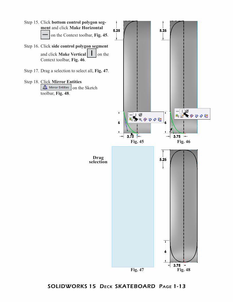
Step 15. Click bottom control polygon seg-ment and click Make Horizontal
on the Context toolbar, Fig. 45.
Step 16. Click side control polygon segment
and click Make Vertical on the Context toolbar, Fig. 46.
Step 17. Drag a selection to select all, Fig. 47.
Step 18. Click Mirror Entities on the Sketch
toolbar, Fig. 48.
Fig. 46Fig. 45
Fig. 48Fig. 47
Drag selection
SOLIDWORKS 15 DecK SKATeBOARD PAge 1-14
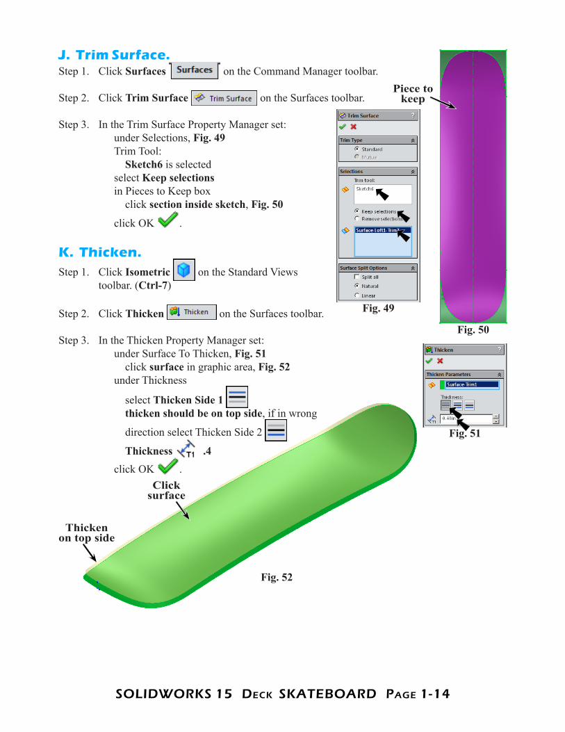
J. Trim Surface.Step 1. Click Surfaces on the Command Manager toolbar.
Step 2. Click Trim Surface on the Surfaces toolbar.
Step 3. In the Trim Surface Property Manager set: under Selections, Fig. 49 Trim Tool: Sketch6 is selected select Keep selections in Pieces to Keep box click section inside sketch, Fig. 50
click OK .
K. Thicken.Step 1. Click Isometric on the Standard Views
toolbar. (Ctrl-7)
Step 2. Click Thicken on the Surfaces toolbar.
Step 3. In the Thicken Property Manager set: under Surface To Thicken, Fig. 51 click surface in graphic area, Fig. 52 under Thickness
select Thicken Side 1 thicken should be on top side, if in wrong
direction select Thicken Side 2
Thickness .4 click OK .
Piece to keep
Fig. 50
Fig. 49
Fig. 51
Fig. 52
Thicken on top side
Click surface
SOLIDWORKS 15 DecK SKATeBOARD PAge 1-15
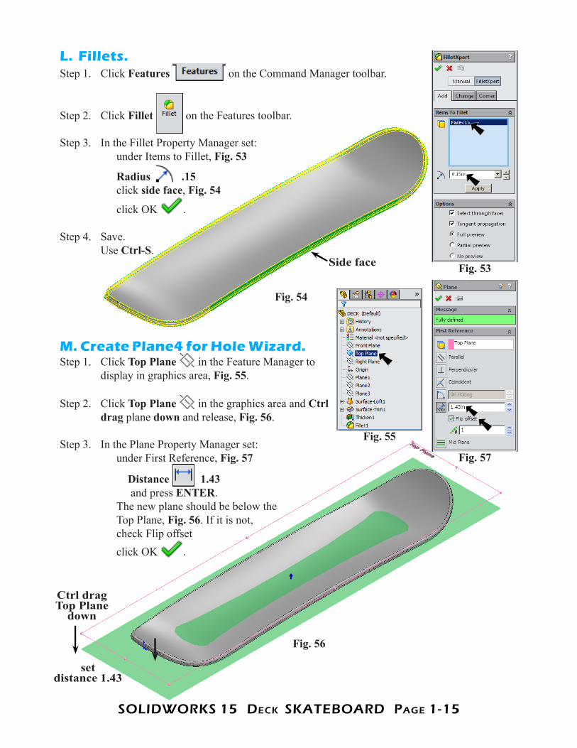
L. Fillets.Step 1. Click Features on the Command Manager toolbar.
Step 2. Click Fillet on the Features toolbar.
Step 3. In the Fillet Property Manager set: under Items to Fillet, Fig. 53
Radius .15 click side face, Fig. 54
click OK .
Step 4. Save. Use Ctrl-S.
M. Create Plane4 for Hole Wizard.Step 1. Click Top Plane in the Feature Manager to
display in graphics area, Fig. 55.
Step 2. Click Top Plane in the graphics area and Ctrl drag plane down and release, Fig. 56.
Step 3. In the Plane Property Manager set: under First Reference, Fig. 57
Distance 1.43 and press ENTER. The new plane should be below the Top Plane, Fig. 56. If it is not, check Flip offset click OK .
Fig. 53Side face
Fig. 54
Fig. 57
Fig. 55
Fig. 56
Ctrl drag Top Plane
down
set
distance 1.43
SOLIDWORKS 15 DecK SKATeBOARD PAge 1-16
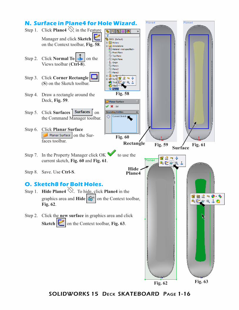
N. Surface in Plane4 for Hole Wizard.Step 1. Click Plane4 in the Feature
Manager and click Sketch on the Context toolbar, Fig. 58.
Step 2. Click Normal To on the Views toolbar (Ctrl-8).
Step 3. Click Corner Rectangle (S) on the Sketch toolbar.
Step 4. Draw a rectangle around the Deck, Fig. 59.
Step 5. Click Surfaces on the Command Manager toolbar.
Step 6. Click Planar Surface on the Sur-
faces toolbar.
Step 7. In the Property Manager click OK to use the current sketch, Fig. 60 and Fig. 61.
Step 8. Save. Use Ctrl-S.
O. Sketch8 for Bolt Holes.Step 1. Hide Plane4 . To hide, click Plane4 in the
graphics area and Hide on the Context toolbar, Fig. 62.
Step 2. Click the new surface in graphics area and click
Sketch on the Context toolbar, Fig. 63.
Fig. 58
Fig. 59Fig. 60
Rectangle Fig. 61Surface
Fig. 62 Fig. 63
Hide Plane4
SOLIDWORKS 15 DecK SKATeBOARD PAge 1-17
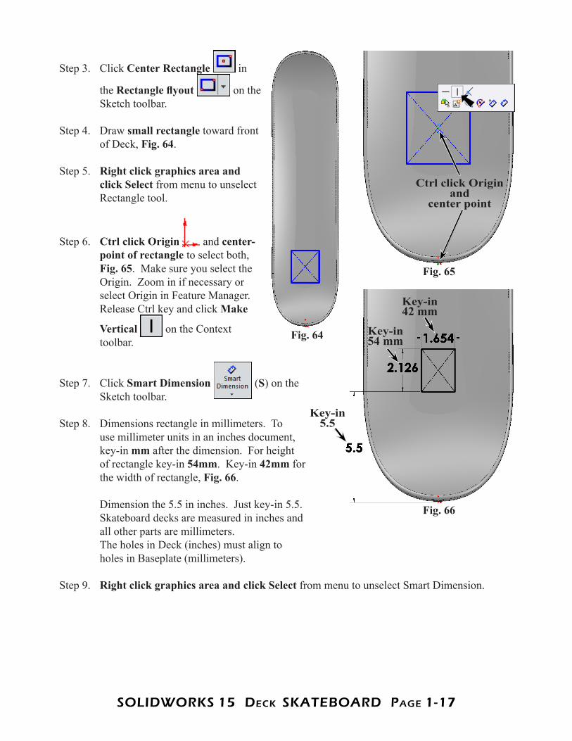
Step 3. Click Center Rectangle in
the Rectangle flyout on the Sketch toolbar.
Step 4. Draw small rectangle toward front of Deck, Fig. 64.
Step 5. Right click graphics area and click Select from menu to unselect Rectangle tool.
Step 6. Ctrl click Origin and center-point of rectangle to select both,Fig. 65. Make sure you select the Origin. Zoom in if necessary or select Origin in Feature Manager. Release Ctrl key and click Make
Vertical on the Context toolbar.
Step 7. Click Smart Dimension (S) on the Sketch toolbar.
Step 8. Dimensions rectangle in millimeters. To use millimeter units in an inches document, key-in mm after the dimension. For height of rectangle key-in 54mm. Key-in 42mm for the width of rectangle, Fig. 66. Dimension the 5.5 in inches. Just key-in 5.5. Skateboard decks are measured in inches and all other parts are millimeters. The holes in Deck (inches) must align to holes in Baseplate (millimeters).
Step 9. Right click graphics area and click Select from menu to unselect Smart Dimension.
Fig. 66
Fig. 64 Key-in 54 mm
Key-in 42 mm
Key-in 5.5
Fig. 65
Ctrl click Origin and
center point
SOLIDWORKS 15 DecK SKATeBOARD PAge 1-18
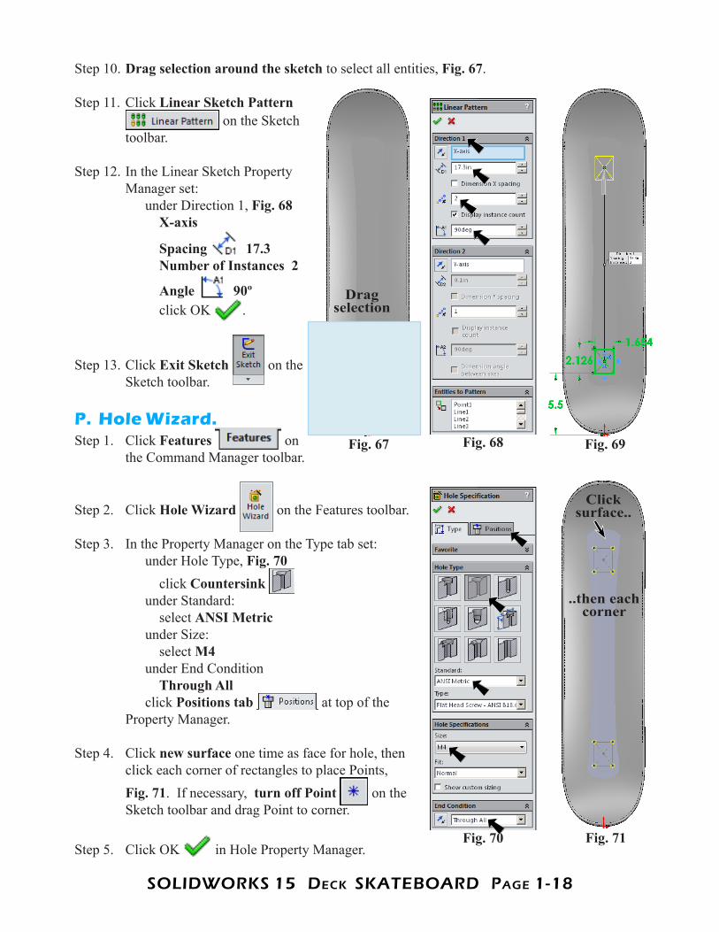
Step 10. Drag selection around the sketch to select all entities, Fig. 67.
Step 11. Click Linear Sketch Pattern on the Sketch
toolbar.
Step 12. In the Linear Sketch Property Manager set: under Direction 1, Fig. 68 X-axis
Spacing 17.3 Number of Instances 2
Angle 90º click OK .
Step 13. Click Exit Sketch on the Sketch toolbar.
P. Hole Wizard.Step 1. Click Features on
the Command Manager toolbar.
Step 2. Click Hole Wizard on the Features toolbar.
Step 3. In the Property Manager on the Type tab set: under Hole Type, Fig. 70 click Countersink under Standard: select ANSI Metric under Size: select M4 under End Condition Through All click Positions tab at top of the Property Manager.
Step 4. Click new surface one time as face for hole, then click each corner of rectangles to place Points, Fig. 71. If necessary, turn off Point on the Sketch toolbar and drag Point to corner.
Step 5. Click OK in Hole Property Manager.
Fig. 68Fig. 67 Fig. 69
Drag selection
Fig. 70 Fig. 71
Click surface..
..then each corner
SOLIDWORKS 15 DecK SKATeBOARD PAge 1-19
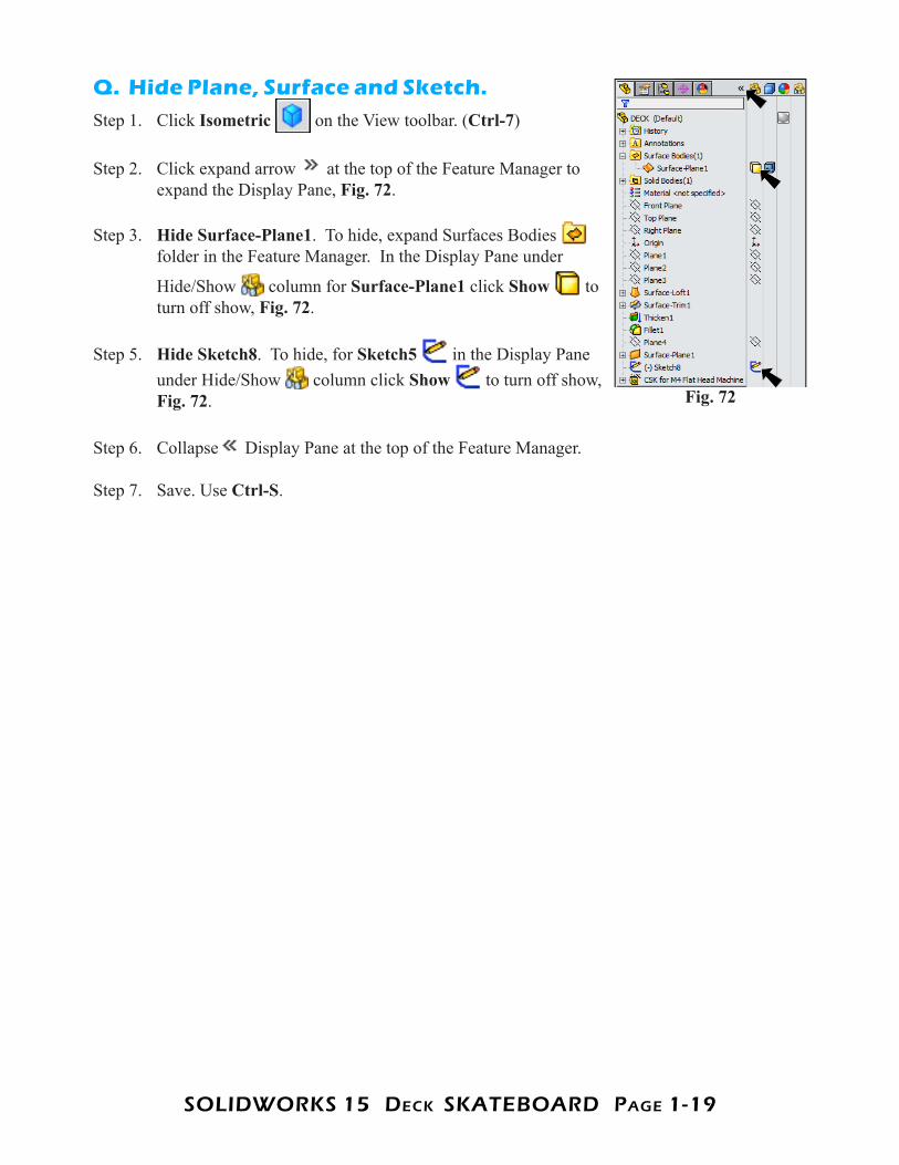
Q. Hide Plane, Surface and Sketch.Step 1. Click Isometric on the View toolbar. (Ctrl-7)
Step 2. Click expand arrow at the top of the Feature Manager to expand the Display Pane, Fig. 72.
Step 3. Hide Surface-Plane1. To hide, expand Surfaces Bodies folder in the Feature Manager. In the Display Pane under
Hide/Show column for Surface-Plane1 click Show to turn off show, Fig. 72.
Step 5. Hide Sketch8. To hide, for Sketch5 in the Display Pane under Hide/Show column click Show to turn off show, Fig. 72.
Step 6. Collapse Display Pane at the top of the Feature Manager.
Step 7. Save. Use Ctrl-S.
Fig. 72
SOLIDWORKS 15 DecK SKATeBOARD PAge 1-20
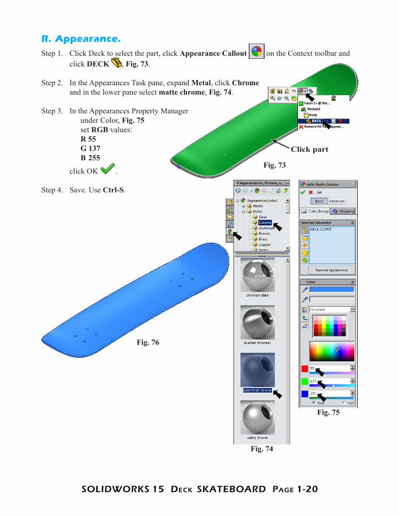
R. Appearance.Step 1. Click Deck to select the part, click Appearance Callout on the Context toolbar and
click DECK , Fig. 73.
Step 2. In the Appearances Task pane, expand Metal, click Chromeand in the lower pane select matte chrome, Fig. 74.
Step 3. In the Appearances Property Manager under Color, Fig. 75 set RGB values: R 55 G 137 B 255
click OK .
Step 4. Save. Use Ctrl-S.
Fig. 73
Click part
Fig. 74
Fig. 75
Fig. 76