a lathe is a machine tool which turns cylindrical … · web viewa lathe is a machine tool which...
TRANSCRIPT

NAME OF LABORATORY: METAL CUTTING & CNC LAB SUBJECT CODE: ME-603NAME OF DEPARTMENT: MECHANICAL ENGINEERING
LAB MANUAL OF METAL CUTTING AND CNC MACHINES (ME-603)
PREPARED BY:
DEEPANJALI GIRI
ASST. PROFESSOR
MECHANICAL ENGG. DEPTT.
LIST OF THE EXPERIMENTS
NAME OF LABORATORY: METAL CUTTING & CNC LAB SUBJECT CODE: ME-603NAME OF DEPARTMENT: MECHANICAL ENGINEERING
SNO NAME OF THE EXPERIMENT PAGE NOFROM TO
1. Study Of Lathe Machine With Various Operations.
2. Study Of Types Of Grinding Machine.
3. Study Of Horizontal And Vertical Milling Machine.
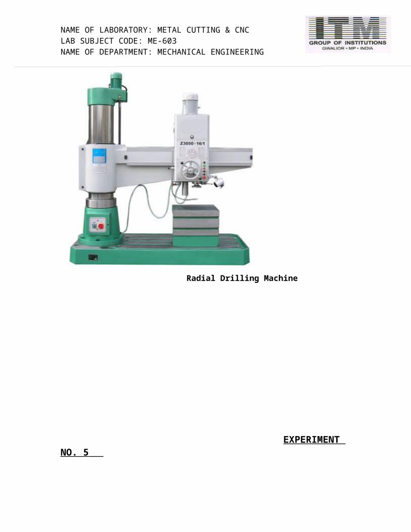
4. Study Of Radial Drilling Machine.
5. Study Of Principle Of Broaching Machine.
6. Study Of Shaper And Quick Return Mechanism.
7. Study Of Gear Cutting On Milling Machine.
8. Study Of Gear Cutting Methods.
9. Study Of Mechatronics.10.
11
NAME OF LABORATORY: METAL CUTTING & CNC LAB SUBJECT CODE: ME-603NAME OF DEPARTMENT: MECHANICAL ENGINEERING
EXPERIMENT NO. 1
Object: Study of Lathe Machine with various Operations.
THEORY:
A lathe is a machine tool which turns cylindrical material, touches a cutting tool to it, and cuts the material. The lathe is one of the machine tools most well used by machining.
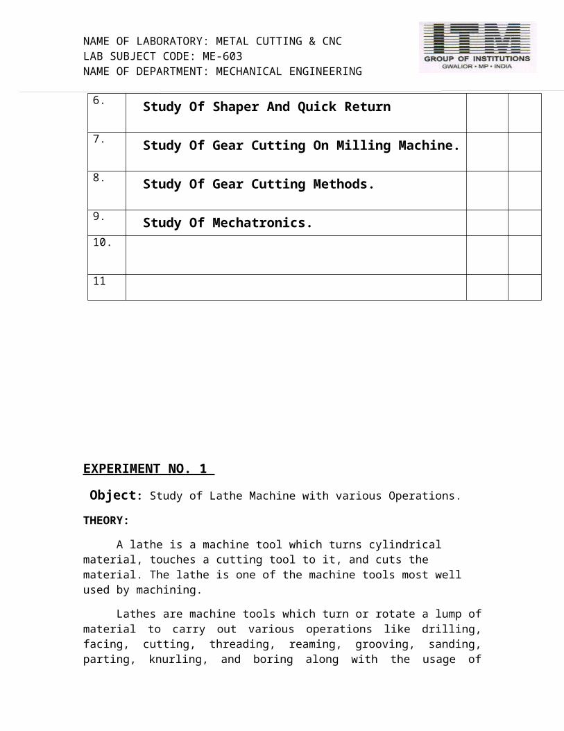
Lathes are machine tools which turn or rotate a lump of material to carry out various operations like drilling, facing, cutting, threading, reaming, grooving, sanding, parting, knurling, and boring along with the usage of cutting tools which are applied to the material to produce an object. The finished product will have symmetry about a rotational axis. The cutting tool moves parallel or perpendicular with respect to workpiece axis to create the desired shape. The typical lathe consists of a headstock, where the spindle is connected to hold the work piece to be machined, gears and speed changing levers. Opposite end of headstock is the tailstock which is a tool holding device. The bed is the base of the lathe which is connected with headstock and allows carriage and tailstock for parallel alignment. A compound rest carries a tool post on which the toolbit is mounted moves along lead screw as shown in Figure no.1, a material is firmly fixed to the chuck of a lathe. The lathe is switched on and the chuck is rotated. And since the table which fixed the byte can be moved in the vertical direction, and the right-and-left direction by operating some handles shown in Fig. 3. It touches a byte's tip into the material by the operation, and make a mechanical part.
Lathe head stock
NAME OF LABORATORY: METAL CUTTING & CNC LAB SUBJECT CODE: ME-603NAME OF DEPARTMENT: MECHANICAL ENGINEERING
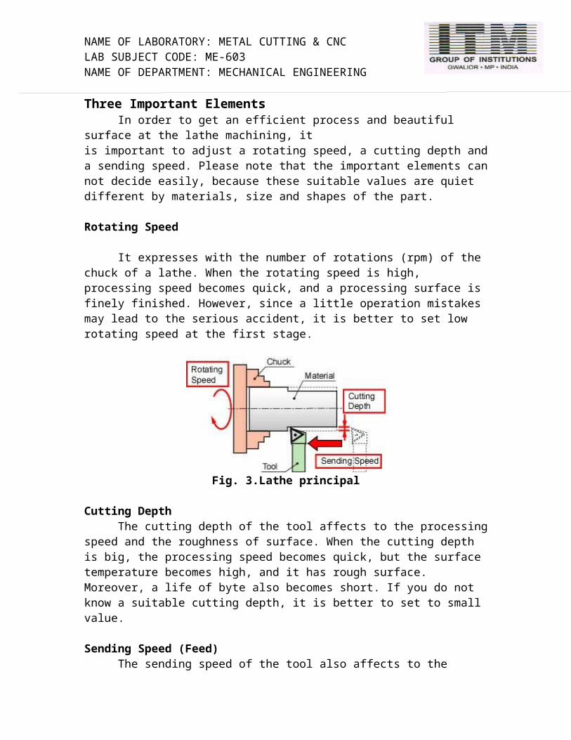
Three Important ElementsIn order to get an efficient process and beautiful surface at the lathe machining, it
is important to adjust a rotating speed, a cutting depth and a sending speed. Please note that the important elements can not decide easily, because these suitable values are quiet different by materials, size and shapes of the part.
Rotating Speed
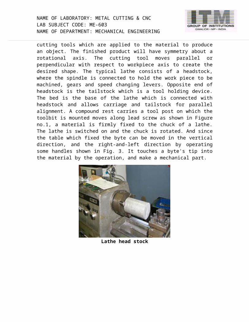
It expresses with the number of rotations (rpm) of the chuck of a lathe. When the rotating speed is high, processing speed becomes quick, and a processing surface is finely finished. However, since a little operation mistakes may lead to the serious accident, it is better to set low rotating speed at the first stage.
Fig. 3.Lathe principal
Cutting DepthThe cutting depth of the tool affects to the processing speed and the roughness of
surface. When the cutting depth is big, the processing speed becomes quick, but the surface temperature becomes high, and it has rough surface. Moreover, a life of byte also becomes short. If you do not know a suitable cutting depth, it is better to set to small value.
Sending Speed (Feed)The sending speed of the tool also affects to the processing speed and the
roughness of surface. When the sending speed is high, the processing speed becomes quick. When the sending speed is low, the surface is finished beautiful. There are 'manual sending' which turns and operates a handle, and 'automatic sending' which advances a byte automatically. A beginner must use the manual sending. Because serious accidents may be caused, such as touching the rotating chuck around the byte in automatic sending,
Cutting Tools for LatheThere are various kinds of the cutting tools for a lathe. We must choose them by
the materials and shape of a part. Three typical cutting tools are introduced in follows. Then we consider what is an easy process or a hard process.
NAME OF LABORATORY: METAL CUTTING & CNC LAB SUBJECT CODE: ME-603NAME OF DEPARTMENT: MECHANICAL ENGINEERING
Form of Typical Cutting Tools
Figure 5(a) shows the most well-used cutting tool called a side tool. It can process to cut an outside surface and an edge surface. Since the material is set at the right of lathe, then this tool can only cut the right of the material.
The cutting tool shown in Figure 5(b) is used at parting and grooving processes. Its pointed end is slim, then it is too weak. Don't add a strong side-force to the tool. This tool must send vertical direction only.
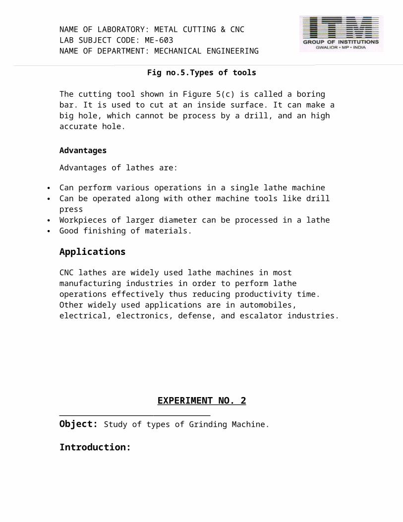
Fig no.5.Types of tools
The cutting tool shown in Figure 5(c) is called a boring bar. It is used to cut at an inside surface. It can make a big hole, which cannot be process by a drill, and an high accurate hole.
Advantages
Advantages of lathes are:
Can perform various operations in a single lathe machine Can be operated along with other machine tools like drill press Workpieces of larger diameter can be processed in a lathe Good finishing of materials.
Applications
CNC lathes are widely used lathe machines in most manufacturing industries in order to perform lathe operations effectively thus reducing productivity time. Other widely used applications are in automobiles, electrical, electronics, defense, and escalator industries.

NAME OF LABORATORY: METAL CUTTING & CNC LAB SUBJECT CODE: ME-603NAME OF DEPARTMENT: MECHANICAL ENGINEERING
EXPERIMENT NO. 2 Object: Study of types of Grinding Machine.
Introduction:
The grinder is a machine that is used for fine surface finishing and the amount of material removed rarely exceeds a few thousands of an inch. These machines have been developed over the years to satisfy specific needs of the industry it serves, so grinding has become specialized, as has turning and milling. The most common types of grinders are the surface grinder, the universal tool and cutter grinder, and the cylindrical grinder Surface grinding is probably the most fundamental of operations. Most shops have a surface grinder even if they don't have a universal cutter grinder of a cylindrical grinder. The basic machine has grinding wheel above the work area which can be fed downward in very small increments into a work piece which is being moved to the left and the right and in and out. This allows the wheel to contact all areas of the surface of the work piece. The grinder is usually equipped with a magnetic plate used to hold the work piece . It is sometimes referred to as a magnetic chuck, although it does not look anything like a lathe chuck . The magnetic chuck holds magnetic materials only. However steel clamps (a magnetic material) can be used to laterally clamp non-magnetic materials for surface grinding.
Theory:
The grinding machine consists of a power driven grinding wheel spinning at the required speed (which is determined by the wheel’s diameter and manufacturer’s rating, usually by a formula) and a bed with a fixture to guide and hold the work-piece. The grinding head can be controlled to travel across a fixed work piece or the workpiece can be moved whilst the grind head stays in a fixed position. Very fine control of the grinding head or tables position is possible using a vernier calibrated hand wheel, or using the features of numerical controls.
Grinding machines remove material from the workpiece by abrasion, which can generate substantial amounts of heat; they therefore incorporate a coolant to cool the workpiece so that it does not overheat and go outside its tolerance. The coolant also benefits the machinist as the heat generated may cause burns in some cases. In very high-precision grinding machines (most cylindrical and surface grinders) the final grinding stages are usually set up so that they remove about 200 nm (less than 1/100000 in) per pass - this generates so little heat that even with no coolant, the temperature rise is negligible.
NAME OF LABORATORY: METAL CUTTING & CNC LAB SUBJECT CODE: ME-603NAME OF DEPARTMENT: MECHANICAL ENGINEERING
Types:
These machines include the:Belt grinder, which is usually used as a machining method to process metals and other materials, with the aid of coated abrasives. Sanding is the machining of wood; grinding is the common name for machining metals. Belt grinding is a versatile process suitable for all kind of applications like finishing, deburring, and stock removal.
Bench grinder, which usually has two wheels of different grain sizes for roughing and finishing operations and is secured to a workbench. It is used for shaping tool bits or various tools that need to be made or repaired. Bench grinders are manually operated.
Cylindrical grinder which includes the centerless grinder. A cylindrical grinder may have multiple grinding wheels. The workpiece is rotated and fed past the wheel/s to form a cylinder. It is used to make precision rods.
Surface grinder which includes the wash grinder. A surface grinder has a "head" which is lowered, and the workpiece is moved back and forth past the grinding wheel on a table that has a permanent magnet for use with magnetic stock. Surface grinders can be manually operated or have CNC controls.
Tool and cutter grinder and the D-bit grinder. These usually can perform the minor function of the drill bit grinder, or other specialist toolroom grinding operations.
Jig grinder, which as the name implies, has a variety of uses when finishing jigs, dies, and fixtures. Its primary function is in the realm of grinding holes and pins. It can also be used for complex surface grinding to finish work started on a mill.
Gear grinder, which is usually employed as the final machining process when manufacturing a high precision gear. The primary function of these machines is to remove the remaining few thousandths of an inch of material left by other manufacturing methods (such as gashing or hobbing).
Fig no.1. Grinding operation

NAME OF LABORATORY: METAL CUTTING & CNC LAB SUBJECT CODE: ME-603NAME OF DEPARTMENT: MECHANICAL ENGINEERING
Grinding spindles Characteristics
Some important characteristics common to many grinding spindles are as follows:
In most grinding spindles, there is an oil/air mist lubrication system with an effective heat dissipation method which helps in simplifying the spindle configuration.
There is the standard spindle range for vertical grinding and horizontal grinding which is developed to enable vertical applications and horizontal applications.
There is also spindle range for internal grinding and motorized main spindle ranges.
Grinding spindles include special solutions to prevent or avoid dirt collection inside.
The spindle design also considers the different vibration behavior of a rotating shaft from vertical and horizontal positions etc.
Grinding spindles: Uses
The grinding efficiency is measured in terms of material removal rate which is attained by employing ultra high wheel speeds. For any ultra high speed grinding machine tool, the spindle is a key component. The various uses of grinding spindles are given below:
The grinding spindle is used for roughing and finishing flat, cylindrical and conical surfaces.
The grinding spindle is used for finishing internal cylinders or bores.
It helps in forming and sharpening cutting tools.
It also helps in snagging or removing rough projections from castings and stampings.
Another important task of grinding spindles is to cleaning, polishing and buffing surfaces.
Types of grinding machine spindles
All spindles are usually classified into three main categories-high frequencies, belt driven or motorized. Other popular types of grinding spindles are:

NAME OF LABORATORY: METAL CUTTING & CNC LAB SUBJECT CODE: ME-603NAME OF DEPARTMENT: MECHANICAL ENGINEERING
Internal grinding spindles: Internal grinding is considered to be the most challenging of all grinding applications. Internal grinding means the precision grinding of the inside surface of the hole in a work piece, enlarging or finishing of the cylindrical opening or inside diameter in a workpiece.
External grinding spindles: External grinding, which is also important to many manufacturing organizations, refers to grinding of the outer surface of a workpiece.
Horizontal grinding spindles: Horizontal grinding spindles are designed to grind advanced materials, including wafer backside grinding operations, achieving a high degree of flatness while at the same time optimizing surface finishes. They are so called because the grinding process takes place in a horizontal way. On machines with horizontal spindle the motor-driven spindles are horizontal. In such machines the parts are guided through the grinding wheels vertically.
Vertical grinding spindles: Vertical grinding , as the name suggests, fixes the workpiece on a rotary chuck in the machine base , similar to the orientation of the workpiece on a vertical lathe. The vertical grinding spindle travels up and down and side to side and at times may also swivel from above the workpiece. On machines with vertical spindle, the motor-driven spindles are vertical and the parts are guided through the grinding wheels horizontally.

NAME OF LABORATORY: METAL CUTTING & CNC LAB SUBJECT CODE: ME-603NAME OF DEPARTMENT: MECHANICAL ENGINEERING
EXPERIMENT NO. 3
Object: Study of Horizontal and Vertical Milling Machine
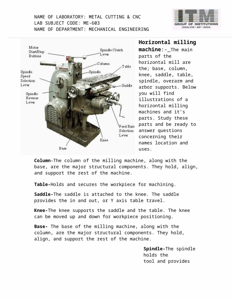
Horizontal milling machine:- The main parts of the horizontal mill are the; base, column, knee, saddle, table, spindle, overarm and arbor supports. Below you will find illustrations of a horizontal milling machines and it’s parts. Study these parts and be ready to answer questions concerning their names location and uses.
Column-The column of the milling machine, along with the base, are the major structural components. They hold, align, and support the rest of the machine.
Table-Holds and secures the workpiece for machining.
Saddle-The saddle is attached to the knee. The saddle provides the in and out, or Y axis table travel.
Knee-The knee supports the saddle and the table. The knee can be moved up and down for workpiece positioning.
Base- The base of the milling machine, along with the column, are the major structural components. They hold, align, and support the rest of the machine.
Spindle-The spindle holds the tool and provides the actual tool rotation.
Spindle Reverse Lever-The position of this lever determines the spindle direction. The three positions of the handle are; In, Middle, and Out. The middle position is the neutral position. Never move the spindle reverse lever when the spindle is turning.

NAME OF LABORATORY: METAL CUTTING & CNC LAB SUBJECT CODE: ME-603NAME OF DEPARTMENT: MECHANICAL ENGINEERING
Spindle Speed Selection Lever-The spindle speed selection lever is used to change the spindle R.P.M. setting. This type of machine has a geared head so the spindle speed can only be changed when the spindle is stopped.
Spindle Clutch Lever-The spindle clutch lever engages the spindle clutch to the motor. By manipulating the spindle clutch lever the operator can start and stop the spindle.
Feed Rate Selection Lever-The feed rate selection lever is used to change the feed rate setting. The feed rate settings are expressed in inches per minute.
Motor Start and Stop Buttons- The motor start and stop buttons control the power to the main motor for the machine
Vertical milling machine:
Vertical milling machine. 1: milling cutter 2: spindle 3: top slide or overarm 4: column 5: table 6: Y-axis slide 7: knee 8: base
In the vertical mill the spindle axis is vertically oriented. Milling cutters are held in the spindle and rotate on its axis. The spindle can generally be extended (or the table can be raised/lowered, giving the same effect), allowing plunge cuts and drilling. There are two subcategories of vertical mills: the bed mill and the turret mill.
A Turret mill has a stationary spindle and the table is moved both perpendicular and parallel to the spindle axis to accomplish cutting. The most common example of this type is the Bridgeport, described below. Turret mills often have a quill which allows the milling cutter to be raised and lowered in a manner similar to a drill press. This type of machine provides two methods of cutting in the vertical (Z) direction: by raising or lowering the quill, and by moving the knee.
In the Bed mill, however, the table moves only perpendicular to the spindle's axis, while the spindle itself moves parallel to its own axis. Turret mills are generally considered by some to be more versatile of the two designs. However, turret mills are only practical as long as the machine remains relatively small. As machine size increases, moving the knee up and down requires considerable effort and it also becomes difficult to reach the quill feed handle (if equipped). Therefore, larger milling machines are usually of the bed type.
Also of note is a lighter machine, called a mill-drill. It is quite popular with hobbyists, due to its small size and lower price. A mill-drill is similar to a small drill press but equipped with an X-Y table. These are frequently of lower quality than other types of machines.
NAME OF LABORATORY: METAL CUTTING & CNC LAB SUBJECT CODE: ME-603NAME OF DEPARTMENT: MECHANICAL ENGINEERING
Advantages:
There is not much of a difference between horizontal and vertical milling machines. Both of these equipments are indispensable in cutting parts uniformly and quickly. These days' horizontal machines are becoming more popular due to its overhead arm and its arbor driven cutters. These are also very easy to operate with few steps to remember. Some of the benefits of using horizontal milling machines are discussed below:
Design and set up: If you are looking to manufacture products which are cost-effective and of high quality, then a vertical milling machine should be of great help. They have scientific designs suitable for dealing with various hard materials. The time taken for this process is minimal and so as the number of steps required operating it. There is no need for a large set up to install these machines and also no need to employ numerous workers. You can have substantially savings on the labor cost, which is often the key setback in a manufacturing environment.Automation and programming: The finished products of vertical machines are of finer quality, with better finishing. As a result, you get the final output, just as you would have planned. Majority of the modern horizontal milling machines are completely automated and requires minimal human intervention. Prior programming and automation result in minimal errors in production, with 25% less processing time.Reduced processing time: These equipments perform diverse functions just like a general machine as well as other activities like tapping and boring. One milling machine performs these in one operation. Advanced milling also reduces the need for manual labor significantly, which significantly reduced the operational cost unlike earlier times. These machines no longer require multiple set ups and change in tools. Horizontal milling machines are advanced and do not require frequent movement of parts, location wise. These advancements have reduced delay in processing time drastically.Arm supports and clutters: Horizontal machines have features of arm supports and clutters, which are driven by an arbor. These two features help to add value in production. You should pay attention to reduce incidence of accidents and ensure maximum safety. Maintenance of cutters is required at a proper interval of time to maintain its sharpness. Check the location of arm support while they awhile dealing with arbors for maximum results.

NAME OF LABORATORY: METAL CUTTING & CNC LAB SUBJECT CODE: ME-603NAME OF DEPARTMENT: MECHANICAL ENGINEERING
EXPERIMENT NO.4
Object: Study of Radial Drilling Machine.
Theory:
Radial drilling machines are used for drilling medium or large diameter holes up to 50 mm in heavy work pieces.When it comes to mechanical machining, radial drilling machine is used for all functions such as drilling, counter boring, spot facing, lapping, screwing reaming, tapping and boring. Radial drilling machines work well with a variety of material such as cast iron, steel, plastic etc. Drilling machines hold a certain diameter of drill (called a chuck) rotates at a specified rpm (revolutions per minute) allowing the drill to start a hole.Radial drills are of three types. With the plain radial drill, the drill spindle is always vertical, and may not swing over any point of the work. The spindle in the half-universal drill may be swung over any point of the work and it may swing in one plane at any angle to the vertical up to complete reversal of the direction of the drill. And the spindle in the full-universal drill can be swung in any plane at any angle to the vertical.
The specialty of radial drilling machine is that they are of robust construction and are designed for heavy duty drilling. The machines need to have all cast parts of fine close grained grey iron casting machined to close tolerance. They have to be subject to rigid inspection at all stages of assembly to ensure accuracy. Superior machines are known for their Grade 1 accuracy. Radial drilling machines having oil bath gearbox and hardened gears tend to have a very long life. The rotation and easy sliding of gears in bearings gives very high reliability. Gears are internally splined and shafts are externally splined.
The radial drilling machines can have 32 mm 125 mm drilling capacity; mt-4 spindle nose; head stock is bored on toss imported boring machine; double column grinded by wmw german-make cylindrical grinders; and has 2425 standard accuracy. The smt 40/1000 dc radial drilling machines are useful in almost every tool room as well as maintenance purpose.
Our radial drilling machines have heavy-duty high precision all-geared drill head with forged steel gears and toughened spindle.
Face milling and keyway milling operations is made easy thanks to the automatic vertical movement of arms as well as horizontal automatic movement of main spindle head. Accurate inclined drilling is made possible with arm lilting at 360 degrees.
NAME OF LABORATORY: METAL CUTTING & CNC LAB SUBJECT CODE: ME-603NAME OF DEPARTMENT: MECHANICAL ENGINEERING
A lot of time is expended due to the changing of the position of work on a machine. In a radial drill machine, the drill table is placed on a solid foundation for holding very heavy
work. When a piece of work is secured on the drill table, the drill spindle may be placed over any part of the work without moving the latter
Construction of Radial Drilling Machine:
The construction details of radial drilling machine are as follows:
The Main Parts of Radial Drilling Machine are:
1. Base:
The base of the machine is a large cast iron material on which is mounted a cylindrical vertical column. The base is provided with T-slots, which help the workpiece to be clamped rigidly to the base of the machine.
2. Vertical column:
The column is a long, cylindrical shaped part fastened rigidly to the base. The column carries a radial arm that can be raised or lowered by means of an electric motor and can be clamped to any desired position. The radial arm can also be rotated (swiveled) in a complete circle around the column.
NAME OF LABORATORY: METAL CUTTING & CNC LAB SUBJECT CODE: ME-603NAME OF DEPARTMENT: MECHANICAL ENGINEERING
3. Drill head:
The drill head is mounted on the radial arm and carries a driving motor and a mechanism for revolving an feeding (power feed) the drill bit into the workpiece. The drill head can be moved horizontally on the guideways provided in the radial arm, and can be clamped to any desired position.With the combination of the movements of radial arm the drill head, it is possible to move the drill bit, and hence generate a hole at any desired position without moving the workpiece.
Radial Drilling Machine

NAME OF LABORATORY: METAL CUTTING & CNC LAB SUBJECT CODE: ME-603NAME OF DEPARTMENT: MECHANICAL ENGINEERING
EXPERIMENT NO. 5
Object: Study of Principle of Broaching Machine
Theory:Broaching is the machining process of cutting a shape by moving a broach cutting
tool, usually just called a broach, over material such as metals or plastics. The broach's rows of teeth, or chisels, progressively increase in size. Each tooth removes the excess material gradually and the desired shape is complete only after the final broach tooth has passed through the material.
The shape found in an internal keyway in a pulley or gear is the most common shape produced by broaching since broaching is the simplest method of cutting internal forms known as splines on gears, sprockets, and hubs. Polygons such as squares are also commonly and easily produced by a broach, especially when a round hole needs to be enlarged into a square or other non-circular shape. Sometimes, broaches are also used to cut external shapes such as slots.
Interestingly, due to the effectiveness of their original concept and design, today's broaching machines and processes have remained mostly the same since the start of the Industrial Revolution. No job is too large or too small for a broach. Numerous materials such as both ferrous and nonferrous metals as well as many types of plastics are suitable for broaching.
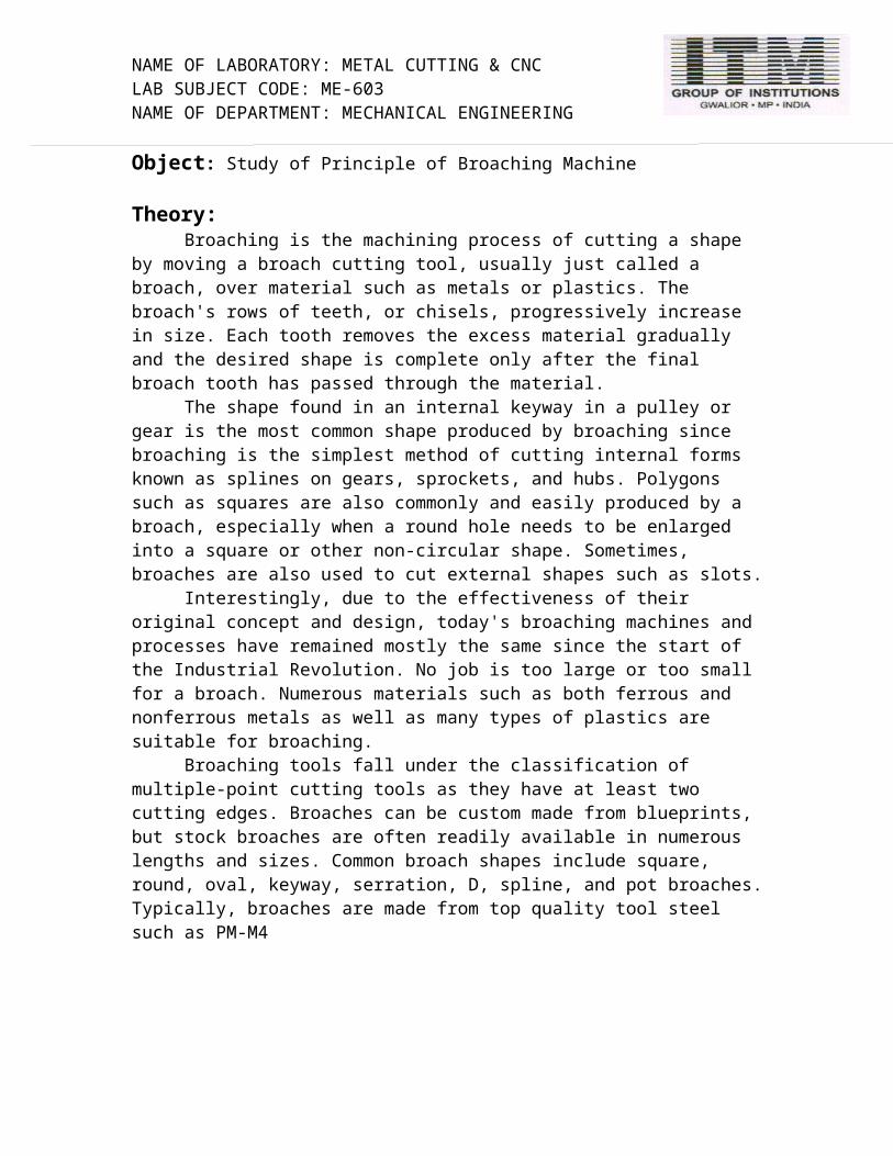
Broaching tools fall under the classification of multiple-point cutting tools as they have at least two cutting edges. Broaches can be custom made from blueprints, but stock broaches are often readily available in numerous lengths and sizes. Common broach shapes include square, round, oval, keyway, serration, D, spline, and pot broaches. Typically, broaches are made from top quality tool steel such as PM-M4
Fig. no.1 broaching tools
NAME OF LABORATORY: METAL CUTTING & CNC LAB SUBJECT CODE: ME-603NAME OF DEPARTMENT: MECHANICAL ENGINEERING
Besides the broach cutting tool itself, fixtures that support the broach are also needed in broaching operations. For example, in keyway broaching, a fixture called a broach horn supports the broach in a shared circular hole.
All broaching operations require proper alignment of the broach and its supportive tooling. Improper alignment will result in cuts that are not perfectly straight. Misalignment can even cause broach breakage. Lubrication is often used in broaching in order to reduce friction, either by applying cutting oil to the material to be cut, or by lubricating the backs of the cutting broaches, depending on the types of broaches and the broaching materials being used.
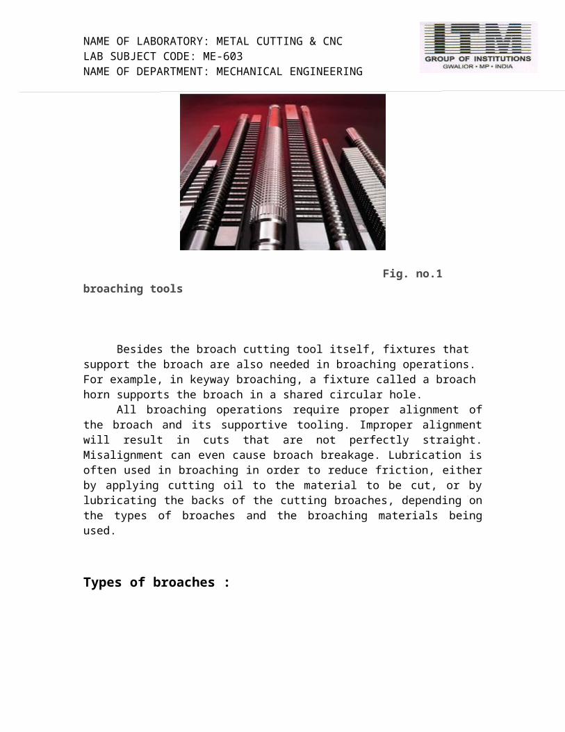
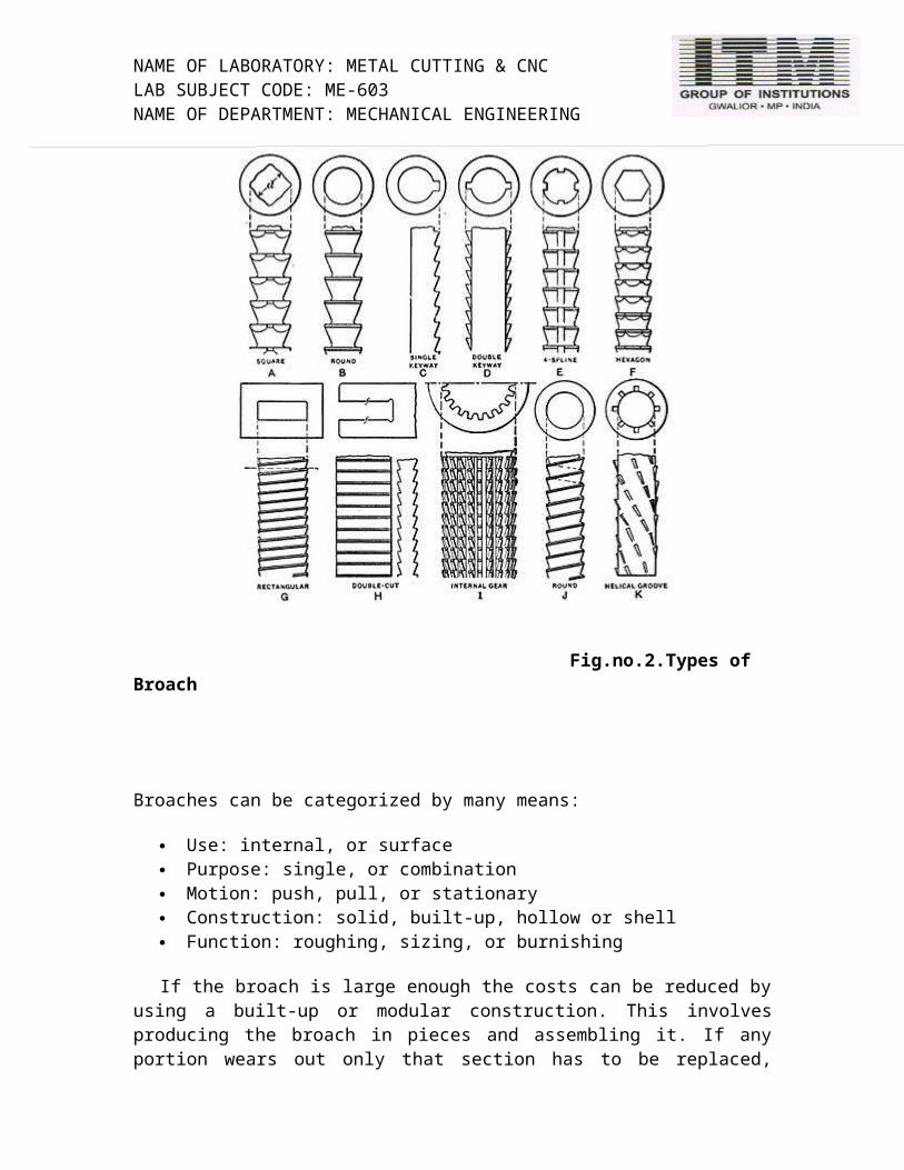
Types of broaches :
Fig.no.2.Types of Broach
NAME OF LABORATORY: METAL CUTTING & CNC LAB SUBJECT CODE: ME-603NAME OF DEPARTMENT: MECHANICAL ENGINEERING
Broaches can be categorized by many means:
Use: internal, or surface Purpose: single, or combination Motion: push, pull, or stationary Construction: solid, built-up, hollow or shell Function: roughing, sizing, or burnishing
If the broach is large enough the costs can be reduced by using a built-up or modular construction. This involves producing the broach in pieces and assembling it. If any portion wears out only that section has to be replaced, instead of the entire broach. Most broaches are made from high speed steel (HSS) or an alloy steel; Tin coatings are common on HSS to prolong life. Except when broaching cast iron, tungsten carbide is rarely used as a tooth material because the cutting edge will crack on the first pass
Surface broaches:The slab broach is the simplest surface broach. It is a general purpose tool for cutting flat surfaces.
Slot broaches (G & H) are for cutting slots of various dimensions at high production rates. Slot broaching is much quicker than milling when more than one slot needs to be machined, because multiple broaches can be run through the part at the same time on the same broaching machine.
Contour broaches are designed to cut concave, convex, cam-, contoured, and irregular shaped surfaces.
Pot broaches are cut the inverse of an internal broach; they cut the outside diameter of a cylindrical workpiece. They are named after the pot looking fixture in which the broaches are mounted; the fixture is often referred to as a "pot". The pot is designed to hold multiple broaching tools concentrically over its entire length. The broach is held stationary while the workpiece is pushed or pulled through it. This has replaced hobbing for some involute gears and cutting external splines and slots.
Straddle broaches use two slab broaches to cut parallel surfaces on opposite sides of a workpiece in one pass. This type of broaching holds closer tolerances than if the two cuts were done independently. It is named after the fact that the broaches "straddle" the workpiece on multiple sides
NAME OF LABORATORY: METAL CUTTING & CNC LAB SUBJECT CODE: ME-603NAME OF DEPARTMENT: MECHANICAL ENGINEERING
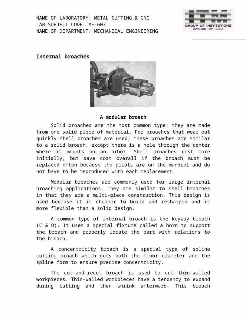
Internal broaches
A modular broachSolid broaches are the most common type; they are made from one solid piece of
material. For broaches that wear out quickly shell broaches are used; these broaches are similar to a solid broach, except there is a hole through the center where it mounts on an arbor. Shell broaches cost more initially, but save cost overall if the broach must be replaced often because the pilots are on the mandrel and do not have to be reproduced with each replacement.
Modular broaches are commonly used for large internal broaching applications. They are similar to shell broaches in that they are a multi-piece construction. This design is used because it is cheaper to build and resharpen and is more flexible than a solid design.
A common type of internal broach is the keyway broach (C & D). It uses a special fixture called a horn to support the broach and properly locate the part with relations to the broach.
A concentricity broach is a special type of spline cutting broach which cuts both the minor diameter and the spline form to ensure precise concentricity.
The cut-and-recut broach is used to cut thin-walled workpieces. Thin-walled workpieces have a tendency to expand during cutting and then shrink afterward. This broach overcomes that problem by first broaching with the standard roughing teeth, followed by a "breathing" section, which serves as a pilot as the workpiece shrinks. The teeth after the "breathing" section then include roughing, semi-finishing, and finishing teeth
An internal broach for cutting splines

NAME OF LABORATORY: METAL CUTTING & CNC LAB SUBJECT CODE: ME-603NAME OF DEPARTMENT: MECHANICAL ENGINEERING
The finishing teeth
The semi-finishing teeth
The roughing teeth
The front pilot
NAME OF LABORATORY: METAL CUTTING & CNC LAB SUBJECT CODE: ME-603NAME OF DEPARTMENT: MECHANICAL ENGINEERING
SPECIAL-BROACHES:
New England Broach engineering has enabled manufacturers to machineparts of unusual size or shape. In each case, the application of the "special"broach has resulted in increased production, reduced down time, and improved product quality on both long and short runs.
ADVANTAGES OF BROACHING: •Produces parts at a high rate. •Removes heavy amounts of stock. •Roughs and finishes in one pass. •Permits the machining of complex contours and simple shapes. •Economical operation. The cost per finished part is lower because of the high production rates
NAME OF LABORATORY: METAL CUTTING & CNC LAB SUBJECT CODE: ME-603NAME OF DEPARTMENT: MECHANICAL ENGINEERING
EXPERIMENT NO.6
Object: Study of Shaper and Quick Return Mechanism.
Theory:
A shaper is a type of Machine tool that uses linear relative motion between the workpiece and a single-point cutting tool to machine a linear toolpath. Its cut is analogous to that of a lathe, except that it is (archetypally) linear instead of helical. (Adding axes of motion can yield helical toolpaths, as also done in helical planing.) A shaper is analogous to a planer, but smaller, and with the cutter riding a ram that moves above a stationary workpiece, rather than the entire workpiece moving beneath the cutter. The ram is moved back and forth typically by a crank inside the column; hydraulically actuated shapers also exist
Types:
Shapers are mainly classified as standard, draw-cut, horizontal, universal, vertical, geared, crank, hydraulic, contour and traveling head.[1] The horizontal arrangement is the most common. Vertical shapers are generally fitted with a rotary table to enable curved surfaces to be machined (same idea as in helical planing). The vertical shaper is essentially the same thing as a slotter (slotting machine), although technically a distinction can be made if one defines a true vertical shaper as a machine whose slide can be moved from the vertical. A slotter is fixed in the vertical plane.Small shapers have been successfully made to operate by hand power. As size increases, the mass of the machine and its power requirements increase, and it becomes necessary to use a motor or other supply of mechanical power. This motor drives a mechanical arrangement (using a pinion gear, bull gear, and crank, or a chain over sprockets) or a hydraulic motor that supplies the necessary movement via hydraulic cylinders.
Operation:
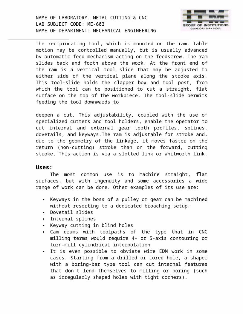
Shaper linkage. Note the drive arm revolves less for the return stroke than for the cutting stroke, resulting in a quicker return stroke and more powerful cutting stroke. A shaper operates by moving a hardened cutting tool backwards and forwards across the workpiece. On the return stroke of the ram the tool is lifted clear of the workpiece, reducing the cutting action to one direction only. The work piece mounts on a rigid, box-shaped table in front of the machine. The height of the table can be adjusted to suit this workpiece, and the table can traverse sideways underneath the reciprocating tool, which is mounted on the ram. Table motion may be controlled manually, but is usually advanced by automatic feed mechanism acting on the feedscrew. The ram slides back and forth above the work. At the front end of the ram is a vertical tool slide that may be adjusted to either side of the vertical plane along the stroke axis. This tool-slide holds the clapper box and tool post, from which the tool can be positioned to cut a straight, flat surface on the top of the workpiece. The tool-slide permits feeding the tool downwards to
NAME OF LABORATORY: METAL CUTTING & CNC LAB SUBJECT CODE: ME-603NAME OF DEPARTMENT: MECHANICAL ENGINEERING
deepen a cut. This adjustability, coupled with the use of specialized cutters and tool holders, enable the operator to cut internal and external gear tooth profiles, splines, dovetails, and keyways.The ram is adjustable for stroke and, due to the geometry of the linkage, it moves faster on the return (non-cutting) stroke than on the forward, cutting stroke. This action is via a slotted link or Whitworth link.
Uses:The most common use is to machine straight, flat surfaces, but with ingenuity and
some accessories a wide range of work can be done. Other examples of its use are:
Keyways in the boss of a pulley or gear can be machined without resorting to a dedicated broaching setup.
Dovetail slides Internal splines Keyway cutting in blind holes Cam drums with toolpaths of the type that in CNC milling terms would require 4-
or 5-axis contouring or turn-mill cylindrical interpolation It is even possible to obviate wire EDM work in some cases. Starting from a
drilled or cored hole, a shaper with a boring-bar type tool can cut internal features that don't lend themselves to milling or boring (such as irregularly shaped holes with tight corners).
Shaper drive mechanisms:
A shaper drive mechanism changes the rotary motion of the power source (Electric motor) into the reciprocating motion of the ram.Metal cutting is carried out during the forward stroke of the ram only; the return stroke of the ram does no cutting and hence is called idle stroke. Since return stroke does no cutting the drive system incorporates a quick return mechanism so that the ram moves faster during return stroke in order to minimize the idle time. The two common mechanism used for this purpose are,
a) Crank and slotted link quick return mechanism
b) Whitworth quick return mechanism
NAME OF LABORATORY: METAL CUTTING & CNC LAB SUBJECT CODE: ME-603NAME OF DEPARTMENT: MECHANICAL ENGINEERING
a) Crank and slotted link mechanism
The crank and slotted link quick return mechanism is shown in figure. Slotted link mechanism is very common in mechanical shapers. This is a simple and compact mechanism. It converts the rotary motion of the electric motor and gear box into the reciprocating motion of the ram. The slotted link mechanism gives the ram a higher velocity during the return non-cutting stroke that during its forward cutting stroke. Thereby the time wasted during the return stroke is reduced.
The bull gear (Fig. a) is driven by a pinion which is connected to the motor shaft through a multi speed gear box. The bull wheel is provided with a slot (Fig b). The crank pin ‘A’ is secured into this slot; simultaneously it can slide in the slotted crank ‘B’. When the bull wheel rotates the crank pin ‘A’ also rotates and side by side slides through the slot in the slotted crank ‘B’. This makes the slotted crank to oscillate about its one end C. This oscillating motion of the slotted crank makes the ram to reciprocate. The intermediate link D is necessary to accommodate the rise and fall of the crank.
The position of the crank pin ‘A’ in the slot in the bull wheel decides the length of the stroke of the shaper. The further it is away from the centre of bull wheel, the longer is the stroke. The cutting stroke of the ram is completed while the crank pin moves from A to Al and the slotted crank goes from left to right. Similarly during the return stroke crank pin moves from Al to A and the link changes its position from right to left.
The time taken by cutting and idle strokes of the ram is proportional to the angles AZA1 and A1ZA respectively.
Cutting time = angle LAZA1
Idle time = angle LA1ZA
NAME OF LABORATORY: METAL CUTTING & CNC LAB SUBJECT CODE: ME-603NAME OF DEPARTMENT: MECHANICAL ENGINEERING
Since the crank pin ‘A’ rotates with uniform velocity and angle LA1ZA is smaller it is obvious that the idle stroke is quicker than the forward cutting stroke. Hence the crank and slotted link mechanism is known as quick return mechanism.
b) Whitworth Quick Return Mechanism:
Whitworth quick return mechanism is shown in figure. Crank BC revolves at a uniform speed. During cutting stroke the point ‘C travels from Y to X through Z. The ram is returned at high speed as the crank rotates from X to Y though ‘T’
Then Time for cutting stroke/ Time for return stroke = 360- 6/6
Since 0 is smaller than 360-0, the time for cutting is more than the idle stroke time. Hence it is known as quick return motion. The stroke length can be changed by varying the radius AE. Since the change in stroke length alters the cutting speed it requires a change of gear to get desired cutting speed.

NAME OF LABORATORY: METAL CUTTING & CNC LAB SUBJECT CODE: ME-603NAME OF DEPARTMENT: MECHANICAL ENGINEERING
EXPERIMENT NO. 7
Object: Study of Gear Cutting on Milling Machine
THEORY:
The gear blank is mounted on a mandrel which is supported between the center of the dividing head and one more center at the other end, as shown in fig. At a time one tooth space is cut by the milling cutter, and a dividing head is used to index the job to the next required tooth space. The cutter is chosen according to the module (or DP) and number of teeth of the gear to the cut. This cutter is mounted on the milling arbor. Before the gear can be cut, it is necessary to have the cutter centered accurately relative to the gear holding mandrel. One way is to adjust the machine table vertically and horizontally until one corner of the cutter just touches the mandrel on one side. Both the dials (of the table and the knee) are then set to zero. The table is then adjusted for the cutter to just touch on the other side of the mandrel with vertical dial showing zero. The reading of the horizontal feed screw is read. This reading divided by two gives the central position of the mandrel relative to the cutter. When the table is set centrally in this manner it should be locked in that position. The table is then fed vertically so that the blank just touches the cutter. The vertical dial is then set to zero. This is required to give the depth of cut on thejob.
With these settings the machine can be started and traversed along the axis of the job to cut the tooth over the whole width of the gear. Depth is increased slowly until it reaches the full depth of the tooth. With the depth setting the backlash of the gear can be controlled suitably. After one tooth space is cut, the blank is indexed through 1/z revolution by means of the dividing head, and the process is repeated until all the teeth are cut.
Fig no.1. Gear cutting on milling
NAME OF LABORATORY: METAL CUTTING & CNC LAB SUBJECT CODE: ME-603NAME OF DEPARTMENT: MECHANICAL ENGINEERING
EXPERIMENT NO. 8
Object: Study of Gear Cutting methods
THEORY:
Gear cutting is the process of creating a gear. The most common processes include hobbing, broaching, and machining; other processes include shaping, forging, extruding, casting, and powder metallurgy. Gears are commonly made from metal, plastic, and wood.
Broaching Processes:
Broaching is a machining process that uses a toothed tool, called a broach, to remove material. There are two main types of broaching: linear and rotary. In linear broaching, which is the more common process, the broach is run linearly against a surface of the workpiece to effect the cut. Linear broaches are used in a broaching machine, which is also sometimes shortened to broach. In rotary broaching, the broach is rotated and pressed into the workpiece to cut an axis symmetric shape. A rotary broach is used in a lathe or screw machine. In both processes the cut is performed in one pass of the broach, which makes it very efficient.Broaching is used when precision machining is required, especially for odd shapes. Commonly machined surfaces include circular and non-circular holes, splines, keyways, and flat surfaces. Typical workpieces include small to medium sized castings, forgings, screw machine parts, and stampings. Even though broaches can be expensive, broaching is usually favored over other processes when used for high-quantity production runs. Broaches are shaped similar to a saw, except the teeth height increases over the length of the tool. Moreover, the broach contains three distinct sections: one for roughing, another for semi-finishing, and the final one for finishing. Broaching is an unusual machining process because it has the feed built into the tool. The profile of the machined surface is always the inverse of the profile of the broach. The rise per tooth (RPT), also known as the step or feed per tooth, determines the amount of material removed and the size of the chip. The broach can be moved relative to the workpiece or vice-versa. Because all of the features are built into the broach no complex motion or skilled labor is required to use it. A broach is effectively a collection of single-point cutting tools arrayed in sequence, cutting one after the other; its cut is analogous to multiple passes of a shaper.For very large gears or splines, a vertical broach is used. It consists of a vertical rail that carries a single tooth cutter formed to create the tooth shape. A rotary table and a Y axis are the customary axes available. Some machines will cut to a depth on the Y axis and index the rotary table automatically. The largest gears are produced on these machines.Other operations such as broaching work particularly well for cutting teeth on the inside. The downside to this is that it is expensive and different

NAME OF LABORATORY: METAL CUTTING & CNC LAB SUBJECT CODE: ME-603NAME OF DEPARTMENT: MECHANICAL ENGINEERING
broaches are required to make different sized gears. Therefore it is mostly used in very high production runs.
Hobbing
Hobbing is a machining process for making gears, splines, and sprockets on a hobbing machine, which is a special type of milling machine. The teeth or splines are
progressively cut into the workpiece by a series of cuts made by a cutting tool called a hob. Compared to other gear forming processes it is relatively inexpensive but still quite accurate, thus it is used for a broad range of parts and quantities.
It is the most widely used gear cutting process for creating spur and helical gears and more gears are cut by hobbing than any other process since it is relatively quick and inexpensive.
Hobbing is a method by which a hob is used to cut teeth into a blank. The cutter and gear blank are rotated at the same time to transfer the profile of the hob onto the gear blank. The hob must make one revolution to create each tooth of the gear. Used very often for all sizes of production runs, but works best for medium to high.
Machining
Conventional machining, one of the most important material removal methods, is a collection of material-working processes in which power-driven machine tools, such as saws, lathes, milling machines, and drill presses, are used with a sharp cutting tool to mechanically cut the material to achieve the desired geometry. Machining is a part of the manufacture of almost all metal products, and it is common for other materials, such as wood and plastic, to be machined. A person who specializes in machining is called a machinist. A room, building, or company where machining is done is called a machine shop. Much of modern day machining is controlled by computers using computer numerical control (CNC) machining. Machining can be a business, a hobby, or both.
The precise meaning of the term "machining" has evolved over the past 1.5 centuries as technology has advanced. During the Machine Age, it referred to (what we today might call) the "traditional" machining processes, such as turning, boring, drilling, milling, broaching, sawing, shaping, planing, reaming, and tapping, or sometimes to grinding. Since the advent of new technologies such as electrical discharge machining, electrochemical machining, electron beam machining, photochemical machining, and ultrasonic machining, the retronym "conventional machining" can be used to differentiate the classic technologies from the newer ones. The term "machining" without qualification usually implies conventional machining.

NAME OF LABORATORY: METAL CUTTING & CNC LAB SUBJECT CODE: ME-603NAME OF DEPARTMENT: MECHANICAL ENGINEERING
Spur may be cut or ground on a milling machine or jig grinder utilizing a numbered gear cutter, and any indexing head or rotary table. The number of the gear cutter is determined by the tooth count of the gear to be cut.
To machine a helical gear on a manual machine, a true indexing fixture must be used. Indexing fixtures can disengage the drive worm, and be attached via an external gear train to the machine table's handle (like a power feed). It then operates similarly to a carriage on a lathe. As the table moves on the X axis, the fixture will rotate in a fixed ratio with the table. The indexing fixture itself receives its name from the original purpose of the tool: moving the table in precise, fixed increments. If the indexing worm is not disengaged from the table, one can move the table in a highly controlled fashion via the indexing plate to produce linear movement of great precision (such as a vernier scale).
There are a few different types of cutters used when creating gears. One is a rack shaper. These are straight and move in a direction tangent to the gear, while the gear is fixed. They have six to twelve teeth and eventually have to be moved back to the starting point to begin another cut.
A popular way to build gears is by form cutting. This is done by taking a blank gear and rotating a cutter, with the desired tooth pattern, around its periphery. This ensures that the gear will fit when the operation is finished.
Shaping
A gear shaper is a machine tool for cutting the teeth of internal or external gears. The name shaper relates to the fact that the cutter engages the part on the forward stroke and pulls away from the part on the return stroke, just like the clapper box on a planer shaper.
The cutting tool is also gear shaped having the same pitch as the gear to be cut. However number of cutting teeth must be less than that of the gear to be cut for internal gears. For external gears the number of teeth on the cutter is limited only by the size of the shaping machine.
For larger gears the blank is usually gashed to the rough shape to make shaping easier
The old method of gear cutting is mounting a gear blank in a shaper and using a tool shaped in the profile of the tooth to be cut. This method also works for cutting internal splines.
Another is a pinion-shaped cutter that is used in a gear shaper machine. It is basically when a cutter that looks similar to a gear cuts a gear blank. The cutter and the blank must have a rotating axis parallel to each other. This process works well for low and high production run
.
NAME OF LABORATORY: METAL CUTTING & CNC LAB SUBJECT CODE: ME-603NAME OF DEPARTMENT: MECHANICAL ENGINEERING
EXPERIMENT NO.9
Object: Study of Mechatronics
Theory:
Mechatronics is the combination of Mechanical engineering, Electronic engineering, Computer engineering, Control engineering, and Systems Design engineering in order to design, and manufacture useful products. Mechatronics is a multidisciplinary engineering system design, that is to say it rejects splitting engineering into separate disciplines.
A mechatronics engineer unites the principles of mechanics, electronics, and computing to generate a simpler, more economical and reliable system. Mechatronics is centered on mechanics, electronics, computing, control engineering, molecular engineering (from nanochemistry and biology), and optical engineering, which, combined, make possible the generation of simpler, more economical, reliable and versatile systems. The portmanteau "mechatronics" was coined by Tetsuro Mori, the senior engineer of the Japanese company Yaskawa in 1969. An industrial robot is a prime example of a mechatronics system; it includes aspects of electronics, mechanics, and computing to do its day-to-day jobs.
Engineering cybernetics deals with the question of control engineering of mechatronic systems. It is used to control or regulate such a system (see control theory). Through collaboration, the mechatronic modules perform the production goals and inherit flexible and agile manufacturing properties in the production scheme. Modern production equipment consists of mechatronic modules that are integrated according to a control architecture. The most known architectures involve hierarchy, polyarchy, heterarchy, and hybrid. The methods for achieving a technical effect are described by control algorithms, which might or might not utilize formal methods in their design. Hybrid systems important to mechatronics include production systems, synergy drives, planetary exploration rovers, automotive subsystems such as anti-lock braking systems and spin-assist, and every-day equipment such as auto focus cameras, video, hard disks, and CD players.

NAME OF LABORATORY: METAL CUTTING & CNC LAB SUBJECT CODE: ME-603NAME OF DEPARTMENT: MECHANICAL ENGINEERING
Application:
Machine vision Automation and robotics Servo-mechanics Sensing and control systems Automotive engineering, automotive equipment in the design of subsystems such
as anti-lock braking systems Computer-machine controls, such as computer driven machines like IE CNC
milling machines Expert systems Industrial goods Consumer products Mechatronics systems Medical mechatronics, medical imaging systems Structural dynamic systems Transportation and vehicular systems Mechatronics as the new language of the automobile Diagnostic, reliability, and control system techniques Computer aided and integrated manufacturing systems Computer-aided design Engineering and manufacturing systems Packaging
Physical implementations:
For most mechatronic systems, the main issue is no more how to implement a control system, but how to implement actuators and what is the energy source. Within the
NAME OF LABORATORY: METAL CUTTING & CNC LAB SUBJECT CODE: ME-603NAME OF DEPARTMENT: MECHANICAL ENGINEERING
mechatronic field, mainly two technologies are used to produce the movement: the piezo-electric actuators and motors, or the electromagnetic actuators and motors. Maybe the most famous mechatronics systems are the well known camera autofocus system or camera anti-shake systems.
Concerning the energy sources, most of the applications use batteries. But a new trend is arriving and is the energy harvesting, allowing transforming into electricity mechanical energy from shock, vibration, or thermal energy from thermal variation, and so on.
Variant of the field:
An emerging variant of this field is biomechatronics, whose purpose is to integrate mechanical parts with a human being, usually in the form of removable gadgets such as an exoskeleton. Such an entity is often identified in science fiction as a cyborg. This is the "real-life" version of cyberware.
Another emerging variant is Electronical or electronics design centric ECAD/MCAD co-design. Electronical is where the integration and co-design between the design team and design tools of an electronics centric system and the design team and design tools of that systems physical/mechanical enclosure takes place.
Disadvantages:
different expertise required more complex safety issues increase in component failures increased power requirements lifetimes change/vary real-time calculations/mathematical models.