a late cretaceous-paleogene cauldron cluster: the nôhi rhyolite, central japan
TRANSCRIPT

Bull Volcanol (1991) 53:132-146
V01(fi 610gy �9 Springer-Verlag 1991
A Late Cretaceous-Paleogene cauldron cluster: the N6hi Rhyolite, central Japan
Yoshimitsu Koido
Department of Earth Science, Faculty of Education, Gifu University, Yanagido 1-1, Gifu 501-11, Japan
Received October 2, 1989/Accepted October 1990
Abstract. The N6hi Rhyolite now occupies an area of about 5000 km 2 in central Japan. It is the largest cluster of volcanic piles of Late Cretaceous to Paleogene age on the Inner Side of SW Japan. It unconformably over- lies Paleozoic to Jurassic rocks and is intruded by Pal- eogene granitic intrusions in its southern and northern parts. The N6hi Rhyolite consists chiefly of rhyolitic to rhyodacitic welded-tuff sheets with subordinate amounts of volcaniclastic sedimentary rocks. Each welded-tuff sheet is usually 200 to 700 m thick, extends laterally 20 to 60 km, and is composed of nearly homo- geneous densely welded tuff. Six volcanic sequences (I- VI) are recognized in the southern and central parts of the N6hi Rhyolite. Each sequence generally comprises successive accumulations of welded-tuff sheets and vol- caniclastic sedimentary layers underlying the sheets. Sequence I, III and V volcanism was derived from zoned magma bodies and was accompanied by grano- diorite porphyries. Sequence II, IV and probably VI vol- canism was derived from homogeneous magma bodies and was not accompanied by granodiorite porphyries. The estimated total volume is of the order of 300- 700 km 3 for Sequences I, II and IV, 1600 km 3 for Se- quence III, and 50 km 3 or less for Sequences V and VI. The volume of Sequence III is one of the largest vol- umes of ashflow turfs so far recognized. One or more polygonal cauldrons, each 15-40 km across and 400- 1000m deep, formed during each of Sequence I through IV. These cauldrons were generally formed by two successive depressions. The first depression in each sequence is of the Motojuku-type, characterized by col- lapse prior to the principal eruption. The second de- pression was formed during the principal eruption. The cauldron of Sequence V has an unusual shape and was probably formed during or after the eruption. The de- velopment of a cauldron in Sequence VI is uncertain. The N6hi Rhyolite is elongate in a NW direction and contains a cluster of seven or eight cauldrons. These cauldrons formed in a tension field trending N and NE, and their volcanism migrated northward. The main re- gional tectonic framework controlling the cauldrons re- sulted from uplifting of the basement, which is ascribed
to the ascent of a large volume of magma in Late Cre- taceous to early Paleogene time.
Introduction
Cretaceous to Paleogene volcanic rocks are extensively distributed on the Inner Side of SW Japan, together with a great amount of granitic rocks (Fig. 1). This vol- canism is characterized by voluminous felsic pyroclas- tic-flow deposits, especially welded tuffs.
The N6hi Rhyolite is a large-scale product of this volcanism in central Japan (Fig. 2). The N6hi Rhyolite extends from the northern margin of the Ry6ke Terrane to the Hida Terrane through the Mino Terrane and Hida Marginal Belt, which are the principal geotec- tonic units in central Japan. It is about 120 km long, about 40 km wide on average, and is elongate in a NW direction. The basement of the N6hi Rhyolite includes the Jurassic Mino Terrane, the Jurassic to Lower Creta- ceous Tetori Group, and Paleozoic igneous and meta- morphic rocks in the Hida Marginal Belt and Hida Ter- rane. The N6hi Rhyolite is intruded by Paleogene gran- itic rocks in its southern and northern parts, and is cov- ered by Miocene sedimentary rocks and Quaternary volcanic rocks. The Atera Fault running through the midst of the N6hi Rhyolite in a NW trend is a left- lateral active fault with a displacement of about 5- 8 km.
The rocks of the N6hi Rhyolite had long been called "quartz porphyries" because of their hypabyssal appearance. Kawada et al. (1961) first recognized that the N6hi Rhyolite consisted chiefly of rhyolitic to rhyo- dacitic welded tufts with subordinate volcaniclastic ma- terial and minor amounts of lava. Hypabyssal rocks also occur, such as granodiorite porphyries and granite porphyries that are co-magmatic with the volcanic rocks (Yamada et al. 1971). The volcanostratigraphy is established for its southern and central parts (Yamada et al. 1971, 1976, 1985; Kawada 1971; C.R.G.N.R. 1973, 1976; Koido 1974, 1989; Shikano 1976; Yamada 1977,

133
~ [ Granitic rocks of Cretaceous to Paleogene age
~ Volcanic rocks ~ NOhi Rhyotit,~ of Cretaceous to Paleogene age
1, Hida Terrane
2. Hida Margina[ Belt
3. M inoTer rane
4. Ry6ke Terrane
5. Maizuru Belt
6. Sangun-Chfigoku Terrane I - S: Itoigawa-Shizuoka Tectonic Line
/
137"00'E N
v v Hida Terrane V V v v ~:~'v \
\
\
\ le
No~ --36"00'N
bkeTerrane \ Younger deposits
& vo Ican ics
Gran i t i c rocks
Grani te porphyr ies & granoaiorite porphyries
par t L++++_' i , NOhi Rhyol i te \ /
~'~ " " 50 Km / / ,
Fig. 1. Cretaceous to Paleogene igneous rocks on the Inner Side of SW Japan and the location of the N6hi Rhyolite (Tanaka and Nozawa 1977). 1-6, principal geotectonic units on the Inner Side of SW Japan Fig. 2. Geological sketch map around the N6hi Rhyolite (simplified from Yamada et al. 1982)
1989; Koido and Sat6 1979; Kawada et al. 1988; Ya- mada and Kobayashi 1988) and for its northern part (C.R.G.N.R. 1979; Kawada 1982). The N6hi Rhyolite has been classified on the basis of these studies into five (I-V) or six (Ia, Ib, II-V) volcanic sequences in its southern and central parts (Yamada et al. 1971; C.R.G.N.R. 1976).
This paper discusses the N6hi Rhyolite as a cluster of cauldrons, most of which have formed by two col- lapses prior to and during the principal eruption. The regional tectonic framework controlling the cauldrons is also described.
Geology of the Nfihi Rhyolite
Stratigraphic units
Individual flow units or cooling units (Smith 1960) are difficult to determine for welded tufts in the N6hi Rhyolite. Hence, a welded-tuff sheet defined by Smith (1960) is used as the primary stratigraphic unit. Each sheet is usually 200 to 700 m thick, and extends later- ally 20 to 60 kin. It consists of nearly homogeneous densely welded tuff, but it has some variation in modal and chemical compositions. Contacts between succes-

134
sive sheets are generally determined by a discontinuous change in general lithofacies. Less welded materials or thin airfall tuffs are recognized neither within each sheet nor at the contact between successive sheets.
Layers of volcaniclastic sediments are intercalated with welded-tuff sheets at several stratigraphic hori- zons. They are composed mainly of various kinds of non-welded turfs, tuffaceous sandstones, mudstones and conglomerates, and are 30 to 400 m in thickness. Most of them are lacustrine deposits. Conglomerates contain pebbles of the underlying welded-tuff sheets and basement rocks in a tuffaceous sandy matrix.
Stratigraphy and volcanic sequence
The N6hi Rhyolite consists of numerous welded- tuff sheets, several interlayered volcaniclastic sediments
and lavas (Table 1). A volcanic sequence is defined here as the successive accumulat ion of welded-tuff sheets and volcaniclastic sedimentary layers underlying the sheet. The older volcaniclastic sedimentary layers of each volcanic sequence unconformably cover the un- derlying welded-tuff sheet. Six volcanic sequences ( I - VI) are recognized in the southern and central parts of the N6hi Rhyolite (see Table 1).
Petrography
Each welded-tuff sheet shows similar petrographic fea- tures, and is composed of abundant crystal fragments, devitrified matrix, essential fragments and lithic frag- ments.
Crystal fragments, commonly smaller than 3 m m and rarely up to 5-6 m m in diameter, are of quartz,
Table 1. Stratigraphic succession in the southern and central parts of the N6hi Rhyolite (after Yamada et al. 1971, 1985; C.R.G.N.R. 1973, 1976; Yamada 1977, 1989; Koido and Sat6 1979; partly modified)
Volcanic Stratigraphic unit [thickness, composition] (Fission-track age, Ma) Sequence (ca. age) Southern part Southern and central parts Central part
Granite porphyry (57.0 + 2.3)
VI-3 W.T.S. [150 m, Rh] VI VI-2 W.T.S. [120-180 m, Rh] (58.2_+3.2) (58 Ma) VI-1 W.T.S. [150-200 m, Rh]
Granodiorite porphyry (63.1 _+ 2.6)
V-4 W.T.S. [300 m, Rd] V V-3 W.T.S. [500 m, Rh-Rd] (66.0 _+ 3.8)
V-2 V.S.L. [50-150 m, --] (63 Ma) V-1 V.S.L. [30 m, --]
IV-4 W.T.S. [350-500 m, Rh] IV IV-3 W.T.S. [250-500 m, Rh]
IV-2 W.T.S. [400-700 m, Rh] (64.5 + 2.5) (65 Ma) IV-1 V.S.L. [50-400 m, --]
Granodiorite porphyry ( - Qdp) (68.8 + 2.7, 72.9 _ 3.1)
III
(70 Ma)
1II-5 W.T.S. [200-400 m, Rd] III-4 W.T.S. [200-300 m, Rh] Ili-3 W.T.S. [700-1000 m, Rd] (67.0_+ 1.5, 72.9+3.1)
III-2S W.T.S. [350 m, Rh] (71.7+4.1) III-2C W.T.S. [300+rn, Rh] III-1S V.S.L. [150 m, Rh] III-1C V.S.L. [?, Rh]
II-4 W.T.S. [500 m, Rh] (76.3 + 4.0, 76.3 + 1.5) II I1-3 V.S.L. [50 m, --] (75 Ma) II-2 W.T.S. [50+m, ?] (72.4_+3.8)
II-1 V.S.L. [50 m, --]
Granodiorite porphyry
I
(80 Ma?)
I-7 Lava [100 m, Da] I-6 W.T.S. [500 m, Rd] 1-5 W.T.S. [500 m, Rh] I-4 V.S.L. [50 m, --] I-3 W.T.S. [150 m, Rh] I-2 W.T.S. [100 m, R.h] I-1 V.S.L. [200 m, --]
W.T.S., Welded-Tuff Sheet; V.S.L., volcaniclastic sedimentary layer; Qdp, quartz diorite porphyry; Rh, rhyolitic; Rd, rhyodacitic; Da, dacitic

plagioclase, alkali feldspar, biotite, hornblende, some- times ortho- and clino-pyroxenes, and rarely olivine, with accessory ilmenite, allanite and zircon. The amounts of these crystals are mostly 30-60 vol.% exclu- sive of lithic fragments. Modal proportions of these crystals vary between sheets in the same volcanic se- quence and have some variation within each sheet (Fig. 3). Plagioclase is mostly calcic oligoclase and andesine (or labradorite) and generally shows normal zoning. Plagioclase is strongly zoned in some rhyodacitic welded tufts. Plagioclase is partly altered to calcite, ser- icite and epidote. Most alkali feldspars are orthoclase; sanidine is rarely found in very fresh rocks. Orthoclase has perthitic and cryptoperthitic structures with optical angles of about ( - ) 40 ~ ~ It is often turbid and are partly altered to calcite. Mafic minerals are commonly from 2 to 5 vol.%. They are characterized by Fe-rich species, namely biotite rich in annite-siderophyllite components, ferroedenite-ferrohornblende, ferroaugite, ferrohypersthene and ferrohortonolite (Kawada 1971; Harayama 1979). Such minerals are frequently found in the equivalent volcanic and plutonic rocks in the sur- rounding areas and are interpreted as primary mag- matic constituents. Most mafic minerals are altered to chlorite, calcite, sericite, magnetite and others.
The matrix is made of dense glass shards, which are completely devitrified into compact cryptocrystalline
Quartz
135
aggregates of salic minerals with traces of welded tex- ture.
Essential fragments have a lenticular to ovoid shape and show a eutaxitic structure. Most of them are smaller than 5 cm but some are up to 30 cm in length. They carry approximately the same assemblage of phe- nocrysts with nearly the same proportions as crystal fragments of enclosing welded tufts. Such fragments are, therefore, interpreted to be cognate with the en- closing welded tufts. Their groundmasses are more coarsely crystallized into aggregates of salic minerals than the devitrified matrix of the enclosing rocks, and often show spherulitic or axiolitic structure without traces of vesicular texture.
Lithic fragments are common in most of the welded tufts and are locally up to 20-30 vol.%. They are very small (less than lmm) to large (more than 10cm across). Accidental fragments are principally of the basement rocks such as sandstone, chert or shale con- stituting the Mino Terrane, and rarely of granitic rocks. Other accessory fragments are of welded tufts and py- roclastic rocks.
Intrusive rocks
Stocks and dikes intrude the adjacent basement rocks as well as the N6hi Rhyolite. They are composed of
x III-5 W.T.S.
§ 111-4 W.T.S.
A III-3 W.T.S.
�9 III- 2S W.T.S.
o III- 2C W.T.S.
Alkati feldspar
V
Fig. 3. Modal composit ion of quartz, alkali feldspar and plagio- clase of the welded-tuff sheets (W.T.S.) in Sequence III of the
�9 X X /
P[agioclase
N6hi Rhyolite (after Yamada et al. 1971; C.R.G.N.R. 1976; Koido and Sat6 1979)
136
granodiorite porphyry, granite porphyry, and subordi- nate quartz diorite porphyry. Quartz diorite porphyry occurs only as the core of a granodiorite porphyry stock.
Granodiorite porphyries carry abundant euhedral phenocrysts of plagioclase, alkali feldspar, quartz, bio- tite and hornblende in a microgranitic or micrographic groundmass. Most marie minerals and some plagio- clase and alkali feldspar are altered to chlorite, calcite, sericite and other minerals. The granodiorite porphy- ries occur as stocks, usually 5 to 10 km in length, within the areas dominated by welded-tuff sheets of Se- quences I and III. One small stock intruded the welded-tuff sheet of Sequence V. The granodiorite por- phyries probably intruded into the vent areas for these sheets, because unusually abundant large lithic frag- ments occur within the sheets in the probable vent ar- eas and small-scale breccia dikes are distributed around them (C.R.G.N.R. 1976; Yamada and Kobayashi 1988).
Granite porphyries contain fewer marie minerals than granodiorite porphyries. They usually occur as dikes or dike swarms several tens or hundreds of meters wide along the margins of, or whithin, the N6hi Rhyo- lite. Zircon fission-track ages suggest that the N6hi Rhyolite was intruded by granite porphyries immedi- ately after Sequence VI volcanism along or near the rims of several cauldrons.
Age of the N6hi Rhyolite
No appropriate minerals occur in either the welded-tuff sheets or the intrusive rocks for determining K-Ar ages, owing to alteration. Hence, fission-track dating of zir- cons was used for age estimations (Harayama and Su- zuki 1984; Yamada et al. 1985; Koido and Danbara 1986; Yamada and Kobayashi 1988). Precise determi- nation of the age for individual sheets or intrusive rocks is impossible, however. Taking into consideration both the stratigraphic succession and the Rb-Sr whole-rock isochron ages of several sheets (Okamoto et al. 1975; Shirahase 1982), I estimate the approximate age of each of the volcanic sequences as follows (see Table 1): Sequence I: ca. 80 Ma Sequence II: 75Ma Sequence III: 70 Ma Sequence IV: 65 Ma Sequence V: 63 Ma Sequence VI: 58 Ma
The age of Sequence I is not well determined, be- cause the rocks have to a great extent been thermally metamorphosed by successive granite intrusions. The intervals between other sequences suggest that the age of Sequence I is ca. 80 Ma. On this basis, the N6hi Rhyolite is inferred to have formed during a long pe- riod of about 20 m.y., from late Cretaceous to early Pal- eogene.
Development of cauldrons in the N~hi Rhyolite
Many of the primary features of the N6hi Rhyolite are poorly preserved owing to later granitic intrusions and
recent block faulting. Thus, the distribution, variation in thickness and original structure of individual welded-tuff sheets are difficult to determine precisely. Their vent areas also are difficult to identify. In spite of these difficulties, however, the spatial relationship of welded-tuff sheets and volcaniclastic sedimentary layers in each volcanic sequence can be roughly de- fined.
The main welded-tuff sheets in Sequence I-V and the volcaniclastic sedimentary layer in Sequence IV were deposited within steep-walled depressions. Their thicknesses change abruptly from several hundred me- ters to several meters at the margins of the depressions. These depressions are interpreted to have been formed by collapse prior to or during accumulation of the main units in each sequence. Granodiorite porphyries or granite porphyries intruded into the probable vent ar- eas within the depression and locally along the margins of the depressions. These depressions probably formed as cauldrons as defined by Smith and Bailey (1968).
The outlines of the cauldrons in each volcanic se- quence are defined below, according to published stud- ies (Yamada et al. 1971, 1985; Kawada 1971; C.R.G.N.R. 1973, 1976; Koido 1974, 1989; Yamada 1977, 1989; Koido and Sat6 1979; Yamada and Ko- bayashi 1988).
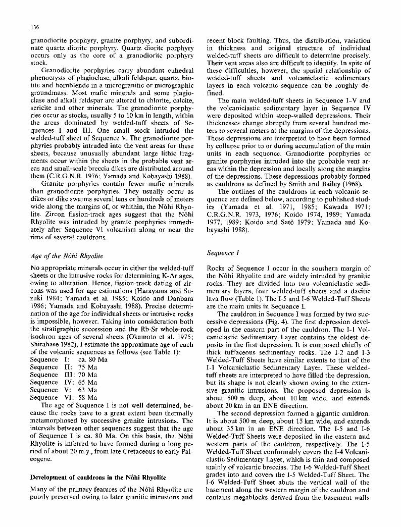
Sequence I
Rocks of Sequence I occur in the southern margin of the N6hi Rhyolite and are widely intruded by granitic rocks. They are divided into two volcaniclastic sedi- mentary layers, four welded-tuff sheets and a dacitic lava flow (Table 1). The I-5 and I-6 Welded-Tuff Sheets are the main units in Sequence I.
The cauldron in Sequence I was formed by two suc- cessive depressions (Fig. 4). The first depression devel- oped in the eastern part of the cauldron. The I-1 Vol- caniclastic Sedimentary Layer contains the oldest de- posits in the first depression. It is composed chiefly of thick tuffaceous sedimentary rocks. The I-2 and I-3 Welded-Tuff Sheets have similar extents to that of the I-1 Volcaniclastic Sedimentary Layer. These welded- tuff sheets are interpreted to have filled the depression, but its shape is not clearly shown owing to the exten- sive granitic intrusions. The proposed depression is about 500m deep, about 10km wide, and extends about 20 km in an ENE direction.
The second depression formed a gigantic cauldron. It is about 500 m deep, about 15 km wide, and extends about 35 km in an ENE direction. The I-5 and I-6 Welded-Tuff Sheets were deposited in the eastern and western parts of the cauldron, respectively. The I-5 Welded-Tuff Sheet conformably covers the 1-4 Volcani- elastic Sedimentary Layer, which is thin and composed mainly of volcanic breccias. The 1-6 Welded-Tuff Sheet grades into and covers the I-5 Welded-Tuff Sheet. The I-6 Welded-Tuff Sheet abuts the vertical wall of the basement along the western margin of the cauldron and contains megablocks derived from the basement walls

i i
~5 4
(
35"3
0
~-
4
~.,", '-" "
-; ', ~.!
W
elde
d-Tu
ff Sh
eet
f'--
~ R
im o
f cau
tdro
n
~ G
rano
dior
ite po
rphy
ry
~I-
7
lav
a
:~:-{+
:~+ I -
6 W
e I de
d-Tu
ff Sh
eet
,::i.:
:.. [
- 5 W
elde
d-Tu
ff S
heet
~ B
asem
ent
",L
+ +
+
j S
eque
nce
II
4--F
13
7"30
'E
~ O
ther
roc
ks
of S
eque
ncel
~ R
im o
f cau
ldro
n
/,-~
R
im o
f fir
st d
epre
s-
sion
lOK
m
5equencel
36~
L~.t3
~ O
ther
Wel
ded-
Tu f f
Sh
eets
of S
eque
nce
Ill
~ lll
- 3
Wel
ded-
Tuff
Shee
t
~ II
I- 2S
We I
ded-
Tuff
Shee
t
• Il
l- 2C
Wel
ded-
Tuff
She
et
7-~
V
olca
nic
rock
s of
Seq
uenc
es I
&II
S
~ Il
1-1
S V
olca
nict
ast i
c S
edim
ents
Lay
er
III-
IC V
olca
nicl
asti
c S
edim
ents
Lay
er
~ U
ndiv
ided
vol
cani
c ...
....
rock
s
~ R
im o
f cau
ldro
ns
~ B
asem
ent
Sequenceli[
Zig
. 4.
Cau
Idro
ns f
orm
ed i
n S
eque
nces
I a
nd I
I Fi
g. 5
. C
auld
rons
for
med
in
Seq
uenc
e Il
I .4

138
of the cauldron. The second depression formed during the accumulation of the 1-5 and 1-6 Welded-Tuff Sheets. Granodiorite porphyry stocks in the northeast- ern part of the cauldron intrude through the probable vent areas of the 1-5 Welded-Tuff Sheet. Those in the western part of the cauldron intrude through the proba- ble vent areas of the 1-6 Welded-Tuff Sheet, and a small vent of this sheet is identified in the western part of the cauldron.
The granitic rocks around the Sequence I cauldron intrude the younger rocks of Sequences II and III and are distributed more widely than the Sequence I caul- dron, so that they have no direct petrogenetic relations to the Sequence I rocks.
Sequence H
The Sequence II rocks are distributed in the western part of the Nrhi Rhyolite (Fig. 4). They are divided into two volcaniclastic sedimentary layers and two welded- tuff sheets (Table 1). The 1I-4 Welded-Tuff Sheet is the main sheet of this sequence.
The II-1 Volcaniclastic Sedimentary Layer is com- posed mainly of conglomerate and accompanied by some intercalated stratified tuffs. Conglomerate con- tains pebbles of the 1-6 Welded-Tuff Sheet, so that ero- sion proceeded before the accumulation of this layer. The II-1 Volcaniclastic Sedimentary Layer is the lowest deposit in the depression. It is uncertain if the depres- sion corresponds to the proposed cauldron in this se- quence, owing to the restricted exposure of the lowest unit. The cauldron was buried mainly by the 1I-4 Welded-Tuff Sheet, but its shape is not clearly shown, because the 1I-4 Welded-Tuff Sheet is widely covered by rocks of Sequences III and IV. The proposed caul- dron is about 500 m deep, about 15 km wide and ex- tends about 35 km in a NW direction. The 11-4 Welded- Tuff Sheet is more than 200 m thick outside the caul- dron. Presumably, the proposed cauldron was formed by the second depression in the same way as was the Sequence I cauldron, and the first depression corre- sponds to that formed prior to the accumulation of the lowest unit. Granodiorite porphyry does not intrude Se- quence II rocks, but granite porphyry occurs as ring dikes along the southern rim of the cauldron.
Sequence III
The III-1S Volcaniclastic Sedimentary Layer in the southern cauldron unconformably covers the Sequence II rocks. It is composed mainly of conglomerate, which is interbedded with stratified tuffs in its lower part. Conglomerate contains pebbles of the 11-4 Welded-Tuff Sheet and Sequence I rocks. The Ill-IS Volcaniclastic Sedimentary Layer was deposited in the depression formed prior to its accumulation. The III-1C Volcani- clastic Sedimentary Layer in the central cauldron is composed chiefly of non-welded rhyolitic tuff breccia and volcanic breccia with pumice fragments, and is commonly accompanied by stratified turfs. It contains megablocks of the basement, which are injected by la- pilli-tuff dikes. The III-1C Volcaniclastic Sedimentary Layer presumably resulted from a phreatic eruption and was deposited within or around its vent area within the depression.
The 11I-3 Welded-Tuff Sheet, the greatest welded- tuff sheet in the N6hi Rhyolite, grades into and covers the II-2S and II-2C Welded-Tuff Sheets in each caul- dron. It is about 700-1000 m thick within both caul- drons and pinches out abruptly outside the cauldrons. The cauldrons formed prior to the accumulation of the upper part of the 111-3 Welded-Tuff Sheet, but it is un- certain if they correspond to the first depression. Most likely they formed as a second depression in the same way as did the Sequence I cauldron. Granodiorite por- phyry stocks intrude through the probable vent areas of the III-2C, III-2S and Ili-3 Welded-Tuff Sheets.
The 111-4 and 111-5 Welded-Tuff Sheets covered flat areas where the cauldrons had been completely buried by the 111-3 Welded-Tuff Sheet, and consequently they show no abrupt change in thickness along the margins of the cauldrons. The Ill-4 Welded-Tuff Sheet contains no accessory fragments of the 111-3 Welded-Tuff Sheet, and it gradually thickens towards the northern side of the southern cauldron. The 111-5 Welded-Tuff Sheet also gradually thickens towards the northwestern side of the southern cauldron. It abouts the basement along the western margins of its exposed areas, where it is in- terstratified with poorly sorted breccias. The breccias are monolithologic, with microbreccias of the same ma- terials as the matrix, and they were derived from the depression walls formed by collapse. From these facts, it is interpreted that these upper sheets probably erupted outside the above-mentioned cauldrons, and a third depression formed during the accumulation of these sheets, but its dimensions are uncertain.
Five welded-tuff sheets and two volcaniclastic sedimen- tary layers formed in this sequence (Table 1), together with two gigantic cauldrons (Fig. 5). One cauldron is about 30 x 20 km across and more than 700 m deep in the southern part of the N6hi Rhyolite, and the other is about 40x25 km across and more than 800-1000 m deep in its central part. The depth is estimated from the thickness of the welded-tuff sheets in the cauldrons, be- cause the cauldron floor is not exposed.
Both cauldrons were filled with the volcanic sedi- mentary layer and the overlying two welded-tuff sheets.
Sequence IV
The Sequence IV rocks are divided into three welded- tuff sheets and one volcaniclastic sedimentary layer (Table 1). The IV-1 Volcaniclastic Sedimentary Layer unconformably covers the III-5 Welded-Tuff Sheet. The cauldrons in this sequence are recognized in the central and southern parts of the N6hi Rhyolite (Fig. 6), but are smaller than those in Sequence III. Grano- diorite porphyry is not recognized in Sequence IV.

__
1
~ V
olca
nic
rock
s of
Seq
uenc
es V
&VI
~ O
ther
Wel
ded-
Tuf
f Sh
eets
of S
eque
nce I
V
N-w
Zel
ded_
Zuf
f She
et
Vol
cani
c ro
cks
of S
eque
nces
I-Il
l 6
I 13
7"30
'E
~ ]V
-1 V
olca
nicl
astic
]
iiii~i~i~
iii~i~i~
S
edim
ents
Laye
r S,
f;
;~l
Ri m
of c
auld
rons
'~ B
asem
ent
5equ
ence
N
2~
i
r5*4
0'N-
~--
~ G
rani
ti c
rock
s
~ G
rani
te p
orph
yry
~ V
olca
nic
rock
s of
Seq
uenc
e V[
~ G
rano
dior
ite porp
hyry
V-z
, W
elde
d-Tu
ff S
heet
~:~4:;
:~ V- ~3
elde
d-Tu
ff S
heet
~]
Vol
cani
c ro
cks
of S
eque
nces
II-l
V
I J
Seq
uenc
e
~ V
-l& 2
Vol
cani
ctas
tic
Sed
imen
ts L
ayer
E
sti m
ated
caul
dron
I"
I
rim o
f Seq
uenc
e V
z-~
Bas
emen
t
Sequ
ence
V
Fig.
7.
Cau
ldro
ns
form
ed i
n S
eque
nce
V.
The
S
eque
nce
VI
volc
anic
roc
ks
are
also
Fi
g. 6
. C
auld
rons
for
med
in
Seq
uenc
e IV
sh
own

140
Two cauldrons occur along the southwestern and northeastern margins of the Sequence III central caul- dron. Both cauldrons have polygonal outlines and were buried by the IV-1 Volcaniclastic Sedimentary Layer and IV-2 Welded-Tuff Sheet. These units in the south- western cauldron abut the steep wall of the basement, along which poorly sorted monolithologic breccias are distributed in the base of the IV-1 Volcaniclastic Sedi- mentary Layer. The southwestern cauldron was appar- ently formed by collapse prior to the accumulation of the lowest unit. The IV-2 Welded-Tuff Sheet buried the cauldron, overflowed both cauldrons, and widely cov- ered the area. Granite porphyries occur as ring dikes along the rims of both cauldrons. The northeastern cauldron is about 20x 10km across and more than 500 m deep, but the dimensions of the southwestern cauldron are uncertain.
The southern cauldron in this sequence formed along the northern margin of the Sequence III southern cauldron. It has a polygonal outline and is about 15 x 10 km across and about 300-400 m deep. It was completely buried by the IV-I Volcaniclastic Sedimen- tary Layer. This layer is composed mainly of non- welded ruffs and tuffaceous sedimentary rocks. It is about 400 m thick within the cauldron and pinches out abruptly outside the cauldron. The IV-2 Welded-Tuff Sheet flowed across flat terrain with no abrupt change in thickness. Whether this sheet erupted within the southern cauldron is unknown. This cauldron is recog- nized only as the steep-walled depression, formed prior to the accumulation of the lowest unit. It is not inter- preted to be a product of regional extension without di- rect relation to volcanism, because the IV-1 Volcani- clastic Sedimentary Layer is accompanied by pyroclas- tic-flow deposits. The source area of the Ill-3 Welded- Tuff Sheet is interpreted to be in the northeastern side of the southern cauldron, judging from the size and vol- ume variations of enclosed lithic fragments. The upper units in this sequence probably erupted and accumu- lated within the second depression, which had formed in the same way as did the second depression in Se- quences I, II and III, but its dimensions are uncer- tain.
Sequences V and II1
The V-3 Welded-Tuff Sheet, the main sheet in Sequence V, is distributed along the eastern margin of the Nrhi Rhyolite in a NW direction (Fig. 7). This sheet proba- bly occupies a cauldron with an unusual shape. The V-1 Volcaniclastic Sedimentary Layer unconformably cov- ers the IV-4 Welded-Tuff Sheet and is composed of tuffaceous sedimentary rocks. It was deposited in a de- pression formed by regional subsidence, because the V- 1 Volcaniclastic Sedimentary Layer is thin but extensive and lacks any abrupt change in thickness. In contrast, the thickness of the V-3 Welded-Tuff Sheet changes abruptly at its contact with be basement. The Sequence VI volcanic rocks directly overlie the basement, with no intervening V-3 Welded-Tuff Sheet, possibly because of
erosion. The cauldron collapse in this sequence proba- bly occurred during or after the eruption of the V-3 Welded-Tuff Sheet. Small granodiorite porphyry stocks and granite porphyry dikes intrude along the rim of the cauldron.
The volcanic rocks in Sequence VI are locally distri- buted along the eastern margin of the N6hi Rhyolite (Fig. 7). They are composed of three welded-tuff sheets that cover both the underlying volcanic rocks and the basement, extending in a NW direction. The develop- ment of a cauldron in Sequence VI is uncertain.
Chemical compositions
Essential fragments for chemical analysis cannot be ob- tained from each welded-tuff sheet. The bulk chemical compositions of the welded turfs exclusive of lithic fragments are therefore used. The bulk compositions are similar to those of enclosed essential fragments that were analyzed, and are correlative with the modal com- positions. Figure 8 shows the SiO2 content and differ- entiation index (Thorton and Tuttle 1960) for each of the welded-tuff sheets, intrusive rocks and lava. The SiO2 contents of the welded tuffs are around 68-77 wt.% (rhyolite to rhyodacite), and those of the lava are 65-67 wt.% (dacite). SiO2 contents are 67-72 wt.% for granodiorite porphyries, 74-77 wt.% for granite porphy- ries, and 66 wt.% for quartz diorite porphyry.
Sequences I to VI are classified into two types of vertical variation for both SiO2 content and D.I. One has a systematic variation (Sequences I, III and V), and the other no variation (Sequences I, IV and VI). The SiO2 content of welded-tuff sheets decreases upward from 77 to 72-74 wt.% for Sequence I and from 77 to 68-72 wt.% for Sequence III. Two cycles of such varia- tion are recognized for Sequence III. Furthermore, the SiO2 content of the later intrusive rocks in both Se- quences I and III is 66-72 tw.%. The dacite lava in Se- quence I is more mafic (65-67 wt.%) than the associated intrusive rocks. The SiO2 content of the V-3 Welded- Tuff Sheet in Sequence V changes upsection from 76 to 72 wt.%. The SiO2 content of associated granodiorite porphyries in Sequence V is 72 wt.%. Such systematic variations in SiO2 content are reflected in the upsection variation of D.I. from 93 to 68-73 for Sequences I and III and from 86 to 79 for Sequence V. This pattern to- ward less silicic compositions with time resembles that observed within single ashflow sheets derived from zoned felsic magma bodies (e.g. Lipman et al. 1966; Bailey et al. 1976; Smith 1979; Hildreth 1981). The gra- dients extending over the grouped sheets for Sequences I and III can not apply just to those of single ashflow sheets. Each sheet in Sequences I and III, however, shows no significant pauses between eruptions. There- fore, both the volcanic rocks and associated granodio- rite porphyries in these sequences are interpreted to have been derived from zoned magma bodies.
The welded tuffs in Sequences II, IV and VI are petrographically and chemically rhyolite and do not show such systematic variation, although the SiO2 con-

141
VOLCANICWELDEDTUFFSHEET(W. INTRUSIVE STAGE T.S.) and LAVA ROCK
G r a n i t e p o r p h y r y
( VI-3 We[ded Tuff Sheet ) VI VI -2 Welded Tuff Sheet
(VI-1 WeLded Tuff Sheet )
V
( V - 4 Welded Tuff Sheet)
V - 3 Welded Tuff Sheet
Granod io r i t e porphyry
IV
IV - 4 Welded Tuff Sheet
( IV -3 Welded Tuff Sheet)
IV- 2 Welded Tuff Sheet
III-5 Welded Tuff Sheet
III - 4 Welded Tuff Sheet
I I I - 3 WeLded Tuff Sheet IIl
II I I - 4 Welded Tuff Sheet
(I I - 2 Welded Tuff Sheet)
Quartz diorite .,porphyry
G ranod io r i t e porphyry
I - 7 Lava
I - 6 Welded Tuff Sheet
[ I - 5 WeIdedTuf f Sheet
I - 3 Welded Tuff Sheet
( I - I Welded Tuff Sheet)
Granod io r i te po rphy ry
S i02 (wt*/o)
i I o
D.I .
I I
64 66
% �9 .%11 ~ 1 7 6 i I T I v I
I i 0 i I ,
% ~
I i i i i i r i
e o �9 �9
r I
~ ". . � 9 ,%... i I i I i i I
. . . . . . . - -
i I i I i I I
; %
I I i I I . . . .
ol i , I
i i ,
68 70 72 74 76 70 80 90 100
Fig. 8. Vertical variations in SiO2 contents and differentiation in- dices of the welded-tuff-sheets, lava and intrusive rocks in the N6hi Rhyolite. Analyses on anhydrous basis. ( ) , no data availa-
ble. Straight lines are simply generalized trend lines (data from Kawada 1971, 1982; Yamada et al. 1971, 1985; C.R.G.N.R. 1973; Koido 1974; Okamoto et al. 1975; present author)
tent and D.I. range from 72 to 76 wt.% and from 80 to 92, respectively. These welded tuffs were apparently de- rived from individual magma bodies with nearly homo- geneous composition. There are no data on the vertical variation in minor elements for these sheets.
Volume
The distribution and thickness variation of individual welded-tuff sheets cannot be precisely determined. The total volume of the sheets for each volcanic sequence
can be roughly estimated, mainly by using the volume of each cauldron (Fig. 9). The estimated volume for each sequence does not indicate that of the correspond- ing magma body, because some magma was widely dis- persed in airfall tephra and also because the volume of granodiorite porphyry concealed under the roof of the volcanic rocks is unknown. Therefore, the values shown in Fig. 9 are generally minimum values of the volume of the corresponding magma body.
The volcanic activity in the N6hi Rhyolite increased abruptly after Sequence II, reached a maximum in Se-

142
Km 3
1,500-
1,000
500- ~oo
oV//S I II
1.600 77-77
/ / / 1 / / / / / / / .. ,. / / / i / / / / / / / /
/ / / / / / / /
U/A
�9 - . / / / A
".'.'." / / / A / . / . / . / / / / A / , / . / . / ~ / / / /
/ / / I
III IV Sequence
5o 5
V V[
Fig. 9. Estimated original total volume of the welded-tuff sheets in each volcanic sequence in the N6hi Rhyolite
quence III, and systematically decreased thereafter. The estimated volume in Sequence III is nearly equal to that of the largest magnitude of ashflow magmatism (Smith 1979).
Discuss ion
Cauldron collapse prior to and during eruption
Volcaniclastic sedimentary layers and thick welded-tuff sheets successively accumulated within the cauldrons in Sequences I-V. The cauldrons were formed by two or three successive depressions. The first depression was filled by lacustrine units in Sequences I-IV. An abrupt change in thickness of the units is recognized at the margins of the polygonal depressions in Sequence IV. The depression shape and the conditions at its margins in Sequences I-III are uncertain. The first depression was formed by collapse prior to accumulation of the lowest sedimentary unit, perhaps as a premonitory de- pression to the principal eruption. The depression is not interpreted to be a regional extensional tectonic feature without direct relation to volcanism, because the lowest units contain some volcanic products. Such a depression is not recognized in the Sequence V caul- dron.
The second or the third depression in each cauldron is probably more extensive than the first depression, and was buried by the main welded-tuff sheets in each sequence. These sheets show no abrupt change in thick- ness along the margins of the first depression, and flowed across a low-relief surface. They abut the steep walls of the Second or the third depression, along which they are interstratified with collapse materials in Se- quences I and III. This depression was formed by col- lapse during the principal eruption. Its shape is poly-
gonal rather than subrounded, but the geometry of the fracture systems bordering the cauldron collapse are unknown owing to lack of deep erosion. The main de- pression in the Sequence V cauldron also was formed by collapse during or after the principal eruption.
Lipman (1984) summarized a general caldera cycle associated with voluminous ashflow eruptions, on the basis of the greater thickness of the intracaldera sheet and the existence of caldera-collapse breccias in many ashflow fields in western North America, and empha- sized that large calderas collapsed concurrently with eruption. The timing of the first collapse events asso- ciated with the N6hi Rhyolite cauldrons was different from that suggested by Lipman (1984).
The experimental study on cauldron formation by Komuro et al. (1984) suggests that an ascending magma body domes the ground surface, and as a result radial and concentric fractures are simultaneously produced on the top of the dome. Komuro et al. (1984) conclude that collapse occurs along these fractures and that a po- lygonal cauldron bounded with normal faults is formed prior to the principal eruption. Komuro (1987) desig- nates the cauldron produced by an ascending magma body as the Motojuku-type cauldron. The Motojuku- type cauldron is often observed in the Miocene vol- canic field in Japan (e.g. Fujita 1972) and is quantita- tively demonstrated also on the Quaternary caldera which has long been accepted to be the Crater Lake- type (Yahata 1989). The concept of the Motojuku-type cauldon is not always controversial within Japan, one of the reasons for which is thought that the commonly expressed concept on the caldera formation - caldera subsidence after the eruption - is difficult to be sub- stantiated quantitatively on the Quaternary large cal- deras. Komuro (1987) shows experimentally that a ring fracture is formed by reduced magma pressure or by evacuation of the magma body after the principal erup- tion.
I believe that the first depression of Sequences I-IV in the N6hi Rhyolite were formed by an ascending magma body prior to the principal eruption and hence is a Motojuku-type cauldron. The second and third de- pressions in each sequence were formed by reduced magma pressure during the principal eruption. Figure 10 presents the development of two cauldrons accord- ing to this model during the Sequence III volcanism, which is the most voluminous volcanic sequence in the N6hi Rhyolite.
Regional tectonic framework of the N6hi Rhyolite mass
The locations of cauldrons migrated northward from Sequence I to II and the subsequent III-VI. The caul- dron in Sequence I is elongate in an ENE direction, but the cauldron in Sequence II on the northern side of the Sequence I cauldron is elongate in a NW direction (Fig. 4). The two cauldrons in Sequence III are situated in a NW direction, parallel to that of the N6hi Rhyolite (Fig. 5). The Sequence V cauldron and Sequence VI rocks have NW trends (Fig. 7). The cauldrons in the

A
/ \ /
143
B
C
Tuff breccia & Votcaniclastie sediments
D Rhyolit ic welded-tuff sheet
F Rhyodacitic wetded-tuff sheet
Fig. 10A-F. Cross sections showing the development of Sequence III volcanism. Width of figure is about 100 km, and its vertical scale is emphasized. A cauldron collapse occurred with the ascent of a magma body, resulting in the depressions. The dimensions of the depressions are uncertain; B volcaniclastic sedimentary layers accumulated in the depressions. They were formed by the collapse of cauldron wall, the inflow of volcanic materials from the sur- rounding area and the first phreatic eruptions; C rhyolitic pyro- clastic flows erupted from the upper part of the magma body, and relatively minor collapse occurred concurrent with their eruption;
D pyroclastic flows buried the depression and formed rhyolitic welded-tuff sheets; E rhyodacitic pyroclastic flows erupted from the lower part of the magma body, and major cauldron collapse about 20-40 km across and about 700-1000 m deep occurred con- current with their eruption. The pyroclastic flows completely bu- ried the depressions and formed thick rhyodacitic welded-tuff sheets; F granodiorite porphyries, which represent the deeper part of the magma body, intruded through the vent areas of the sheets and along the fractureS bounding the depressions

144
13
36~ ~
35ON+ " ,.
~ Naegi-Agematsu Granite
~ Naeg i-Agernatsu Granite concealed under the N. R.
~ Inagawa Granite
~ Inagawa Granite concealed under the N.R.
20 Km I I
N6hi Rhyolite(N.R.)
-~] Other granitic rocks in the Ry6ke Terrane
~ / ~ Rybke metamorphic rocks and basic rocks
~ ~ Rocks constituting the Mino Terrone(basement of t he N .R . )
Fig. 11. Elongation of granitic bodies around the N6hi Rhyolite (compiled from Ry6ke Research Group 1972; Yamada et al. 1974). The Inagawa Granite and the southern part of the Naegi-Agematsu Granite in and around the Sequence I cauldron are elongate in a ENE direction. The northern part of the Naegi-Agematsu Granite, interpreted to be concealed under the cauldrons of Sequences II-V, is elongated toward the NW
N6hi Rhyolite were apparently controlled by the re- gional tectonic framework of ENE and NW direc- tions.
Different directions of elongation in Sequences I and II-V also characterize granitic intrusions (Fig. 11). Those in and around the Sequence I cauldron are ar- ranged in a ENE direction, and the granitic intrusions concealed under the Sequences II-V cauldrons are elongate in a NW direction. These directions resemble those of the cauldron themselves. The granitic intru- sions were formed successively after the formation of the cauldrons, so that the regional stress pattern is con- sidered to have existed during the periods of both the N6hi Rhyolite volcanism and granitic intrusions, at least from ca. 80 Ma to 58 Ma.
The orientation of the regional tectonic framework controlling both the N6hi Rhyolite volcanism and gra- nitic intrusions indicates a tension field trending both N and NE. The tension field is recognized also in the equivalent volcanic fields on the Inner Side of SW Ja- pan (Tainosho et al. 1985; Iizumi et al. 1985), and it
was characteristic of Late Cretaceous to early Paleo- gene age on the Inner Side of SW Japan. These tectonic fields have different directions in each district and ap- parently resulted from extensional stress due to base- ment uplift rather than only by a regional horizontal tensile stress. I presume that basement uplift was caused by emplacement of a large volume of magma, from which the N6hi Rhyolite volcanism and granitic intrusions were derived. Igneous activity occurred ex- tensively and continually on the Inner Side of WS Ja- pan during this period (Fig. 1), and the tension field has been preserved for a long time. The N6hi Rhyolite vol- canism formed the tension field, and the cauldron clus- ter was so arranged.
Conclusions
1. The southern and central parts of the N6hi Rhyolite are divided into six volcanic sequences (I-VI). Se- quence I, III and V volcanism was derived from zoned

145
m a g m a bod i e s , and Sequence I I , IV and , p r o b a b l y , VI v o l c a n i s m was fed f rom h o m o g e n e o u s m a g m a b o d - ies. 2. One or m o r e p o l y g o n a l cau ld rons , a b o u t 15-40 k m across a n d a b o u t 400-1000 m deep , were f o r m e d in Se- quences I - IV . These c a u l d r o n s were gene ra l ly f o r m e d by two or th ree success ive depress ions . The first dep re s - s ion in each c a u l d r o n is cha r ac t e r i z ed by c o l l a p s e p r i o r to the p r i n c i p a l e r u p t i o n and is c o n s i d e r e d as an exam- p le o f a M o t o j u k u - t y p e cau ld ron . The s econd a n d th i rd d e p r e s s i o n s were f o r m e d by co l l apse du r ing the p r inc i - pa l e rup t ion . 3. The N 6 h i Rhyo l i t e is a c a u l d r o n c lus ter c o n t r o l l e d by the r eg iona l t ec ton ic f r a m e w o r k in E N E a n d N W direc- t ions. This t ec ton ic f r a m e w o r k is a t ens ion f ie ld re- su l t ed f rom up l i f t ing o f the basemen t . Up l i f t i ng is as- c r ibed to a scen t o f a la rge v o l u m e o f m a g m a in Late C r e t a c e o u s to P a l e o g e n e age.
Acknowledgements. I wish to express my sincere thanks to Dr. N. Yamada of the Geological Survey of Japan and the staff members of the Collaborative Research Group for the N6hi Rhyolite for constructive discussions at the various stages of this work. I am also grateful to Prof. K. Suwa of Nagoya University and Prof. Y. Katsui of Hokkaido University for their critical reading of the
manuscript, and to Dr. Y. Shibasaki of Government Industrial Research Institute, Nagoya for the use of XRF. Critical reviews of the manuscript by P. W. Lipman and D. A. Swanson are gratefully acknowledged.
References
Bailey RA, Dalrymple GB, Lanphere MA (1976) Volcanism, structure and geochronology of Long Valley caldera, Mono County, California. J Geophys Res 81:725-744
C.R.G.N.R. (Collaborative Research Group for the N6hi Rhyo- lite) (1973) Stratigraphy and volcanic history of the N6hi Rhyolite in its eastern marginal part. Earth Science (Chikyu Kagaku) 27:161-179 (in Japanese with English abstract)
CRGNR (1976) Stratigraphy and volcanic history of the N6hi Rhyolite in its western parts. Earth Science (Chikyu Kagaku) 30:193-205 (in Japanese with English abstract)
CRGNR (1979) Stratigraphy and outline of the volcanic history of the N6hi Rhyolite in its northern part. Mem Geol Soc Jpn 17:165-176 (in Japanese with English abstract)
Fujita Y (1972) The law of generation and development of the Green Tuff orogenesis. Pacific Geol 5: 89-116
Harayama S (1979) Chemical properties of marie mineral from Cretaceous acid volcanic rocks, central Japan. MAGMA 56:23-29 (in Japanese)
Appendix
The Japanese usage of welded-tuff sheet, volcaniclastic sedimentary layer (V.S.L.) and lava used in this paper is shown as follows
This paper Japanese usage
VI-3 Welded-Tuff Sheet VI-2 Welded-Tuff Sheet VI-1 Welded-Tuff Sheet
1748 m Peak Welded-Tuff Sheet Suzukasawa Welded-Tuff Sheet Senzawa Welded-Tuff Sheet
V-4 Welded-Tuff Sheet V-3 Welded-Tuff Sheet V-2 V.S.L. V-I V.S.L.
Sotobayama Welded-Tuff Sheet Setogawa Welded-Tuff Sheet Kurosawa Breccia Formation Shirakawa Formation
IV-4 Welded-Tuff Sheet IV-3 Welded-Tuff Sheet IV-2 Welded-Tuff Sheet IV-1 V.S,L.
Uguigawa Welded-Tuff Sheet Mayumit6ge Welded-Tuff Sheet Takadaru Welded-Tuff Sheet Atera Formation
III-5 Welded-Tuff Sheet III-4 Welded-Tuff Sheet III-3 Welded-Tuff Sheet III-2S Welded-Tuff Sheet III-2C Welded-Tuff Sheet III-IS V.S.L. III-1C V.S.L.
Yfimoriyama Welded-Tuff Sheet Akaishi Welded-Tuff Sheet Higashimata Welded-Tuff Sheet Kirikoshit6ge Welded-Tuff Sheet S6shima Welded-Tuff Sheet Futatsumoriyama Conglomerate Formation Osaka Pyroclastic Rocks
II-4 Welded-Tuff Sheet II-3 V.S.L. II-2 Welded-Tuff Sheet II-1 V.S.L.
Ak6 Welded-Tuff Sheet Volcanic Breccia Kumuro Welded-Tuff Sheet Kasuri Conglomerate Formation
I-7 Lava I-6 Welded-Tuff Sheet I-5 Welded-Tuff Sheet I-4 V.S.L. I-3 Welded-Tuff Sheet I-2 Welded-Tuff Sheet I-1 V.S.L.
Kasagiyama Lava Agigawa Welded-Tuff Sheet Enasan Welded-Tuff Sheet Volcanic Breccia Ichinosawa Welded-Tuff Sheet Kuroisawa Welded-Tuff Sheet Tozawa Formation

146
Harayama S, Suzuki T (1984) Fission-track ages of the Nrhi Rhyolite. Abstr Issue 91st Ann Meet Geol Soc Jpn:367 (in Ja- panese)
Hildreth W (1981) Gradients in silicic magma chambers: Implica- tions for lithospheric magmatism. J Geophys Res 86:10 153- 10192
Iizumi S, Sawada Y, Sakiyama T, Imaoka T (1985) Cretaceous to Paleogene magmatism in the Chugoku and Shikoku districts, Japan. Earth Science (Chikyu Kagaku) 39:372-384 (in Japanese with English abstract)
Kawada K (1971) Geology and petrology of the Nrhi Rhyolites, with special reference to those along the Hida river. Geoi Surv Jpn Rep 243: 51 pp
Kawada K (1982) Geology of the Mikkamachi district. Quadran- gle Ser., scale 1:50000, Geol Surv Jpn 72p (in Japanese with English abstract)
Kawada K, Yamada N, Isomi H, Murayama M, Katada M (1961) Geology of Japanese Central Alps and its western area (2) Nrhi rhyolites. Earth Science (Chikyu Kagaku) 54:20-31 (in Japanese with English abstract)
Kawada K, Isomi H, Sugiyama Y (1988) Geology of the Hagiwara district. With Geological Sheet Map at 1:50000, Geol Surv Jpn 82 p (in Japanese with English abstract)
Koido Y (1974) The Nrhi rhyolite in the eastern part of Gero-chr, Gifu Prefecture, central Japan - with special reference to the subdivision of the Akaishi Welded Tuff Sheet -. J Geol Soc Jpn 80:307-322 (in Japanese with English abstract)
Koido Y (1989) A geological restoration of cauldron in the Late Cretaceous to Paleogene Nrhi rhyolite mass - an example of volcanic stage III in its western margin, Wara-mura, Gifu Pre- fecture, Central Japan. Monograph Assoc. Geol. Collab. Jpn 36:35-40 (in Japanese with English abstract)
Koido Y, Sat6 K (1979) Stratigraphy and volcanic history of the N6hi Rhyolite in its central parts. J Fac Edu Gifu Univ Nat Sci 6:438-446 (in Japanese with English abstract)
Koido Y, Danbara T (1986) Fission-track ages of the welded tuff sheets belonging to the Stage Ib and II in the southern part of the Nrhi Rhyolite mass. Abstr Issue 93rd Ann Meet Geol Soc Jpn:390 (in Japanese)
Komuro H (1987) Experiments on cauldron formation: a poly- gonal cauldron and ring fractures. J Volcanol Geotherm Res 31:139-149
Komuro H, Fujita Y, Kodama K (1984) Numerical and experi- mental models on the formation mechanism of collapse basins during the Green tuff orogenesis of Japan. Bull Volcanol 47: 649-666
Lipman PW (1984) The roots of ash flow calderas in western North America: windows into the tops of granitic batholiths. J Geophys Res 89:B10 8801-8841
Lipman PW, Christiansen RL, O'Conner JT (1966) A composi- tionally zoned ash flow sheet in southern Nevada. US Geol Surv Prof Pap 524-F:47 pp
Okamoto K, Nohda S, Masuda Y, Matsumoto T (1975) Signifi- cance of Cs/Rb ratios in volcanic rocks as exemplified by the Nrhi Rhyolite complex, Central Japan. Geochem J 9:201- 210
Ryrke Research Group (1972) The mutual relations of the granitic rocks of the Ryrke metamorphic belt in central Japan. Earth Science (Chikyu Kagaku) 26:205-216 (in Japanese with Eng- lish abstract)
Shikano K (1976) The Nrhi Rhyolite in the northern part of Na- katsugawa-shi, Gifu Prefecture, central Japan, with special ref- erence to the accretionary lapilli. Earth Science (Chikyu Kaga- ku) 32:225-235 (in Japanese with English abstract)
Shirahase T (1982) Rubidium-strontium ages and strontium iso- tope ratios of the late Cretaceous felsic volcanic rocks in Cen- tral Japan. Abstr Issue 5th Intern Conf Geochronol Cosmo- chronol Isotope Geo1:348
Smith RL (1960) Ash flows. Geol Soc Am Bull 71:795-841 Smith RL (1979) Ash-flow magmatism. Geol Soc Am Spec Pap
180:5-27 Smith RL, Bailey RA (1968) Resurgent cauldrons. Geol Soc Am
Mem 116:613-662 Tainosho Y, Wadatsumi K, Masaoka K, Collaborative Research
Group for the Granites around Lake Biwa (1985) Late Creta- ceous to Paleogene igneous activities in the Kinki district, Ja- pan. Earth Science (Chikyu Kagaku) 39:358-371 (in Japanese with English abstract)
Tanaka K, Nozawa T (ed) (1977) Geology and mineral resources of Japan, 3rd edn. Geol Surv Jpn, 430 pp
Thorton CP, Tuttle OF (1960) Chemistry of igneous rocks I. Dif- ferentiation index. Am J Sci 258:664-684
Yahata M (1989) The Kutcharo caldera - a consideration on the relationship between the basement structure and the formation of caldera -. Monograph Assoc Geol CoUab Jpn 36:191-208 (in Japanese with English abstract)
Yamada N (1977) N6hi Rhyolite and associated granitic rocks. In: Yamada N, Nozawa T, Hayama Y (eds) Mesozoic felsic igneous activity and metamorphism in central Japan - from Nagoya to Toyama. Guidebook for excursion 4. Geol Surv Jpn, pp 33-60
Yamada N (1989) Late Cretaceous Ena Cauldron found in the southernmost part of the Nrhi Rhyolite mass, central Japan. Monograph Assoc Geol Collab Jpn 36:21-33 (in Japanese with English abstract)
Yamada N, Kawada K, Morohashi T (1971) The Nrhi rhyolite as pyroclastic flow deposit. Earth Science (Chikyu Kagaku) 25:25-88 (in Japanese with English abstract)
Yamada N, Sakamoto T, Nozawa T, Enda A (ed) (1974) Geologi- cal map of the Kanazawa, scale 1:200000. Geol Surv Jpn
Yamada N, Sud6 S, Kakimi T (1976) Tectonic map around the Atera fault, central Japan, scale 1:50000. Geol Surv Jpn Mist Map Ser 19
Yamada N, Teraoka Y, Hata M (chief ed) (1982) Geological map of Japan, scale 1:1000000. Geol Atlas Jpn 3-19, 22-25. Geoi Surv Jpn
Yamada N, Adachi M, Kajita S, Harayama S, Yamazaki H, Bunno M (1985) Geology of the Takayama district. Quadran- gle Ser, scale 1:50000, Geol Surv Jpn, 111 p (in Japanese with English abstract)
Yamada N, Kobayashi T (1988) Geology of the On-takesan dis- trict. With Geological Sheet Map at 1:50 000, Geol Surv Jpn 136 p (in Japanese with English abstract)