a high-level pedagogical 3d modeling language and framework
TRANSCRIPT
A High-Level Pedagogical 3D Modeling Language andFramework
Filipe André Cabecinhas
Dissertação para obtenção do Grau de Mestre emEngenharia Informática e de Computadores
Júri
Presidente: Prof. Joaquim Armando Pires JorgeOrientador: Prof. António Paulo Teles de Menezes Correia LeitãoVogal: Prof. João Manuel Pinheiro Cachopo
Maio 2010

2

Acknowledgements
For all his hard work, for being available to discuss ideas with me even when faced with a busy scheduleand for accepting to advise me during the course of this work, I thank my advisor, Professor AntónioLeitão.
For everyone that has supported me throughout my degree, my friends and family, I thank them forencouraging me. A special thank you goes to Andreia, for everything...
Lisbon, May 14, 2010Filipe André Cabecinhas


I do not fear computers. I fear lack of them.— Isaac Asimov

Resumo
As ferramentas de CAD são usadas por pessoas que realizam uma ampla gama de tarefas para a con-strução de edifícios ou outros projectos de desenho (e.g. arquitectos e engenheiros). Algumas destas tare-fas são muito repetitivas e podem sofrer alterações ao longo do projecto, o que pode implicar recomeçaro desenho do início. Outras tarefas podem precisar de interpolação de funções matemáticas para mod-elar a visão do arquitecto, como pode ser visto na forma do museu Guggenheim em Bilbao ou na “PálaSiza Vieira”, em Lisboa. Mas as linguagens de modelação tridimensionais disponíveis actualmente nãosão usáveis por pessoas que, como os arquitectos, não têm uma sólida formação em programação. Nestetrabalho propomos uma linguagem de programação simples, adequada ao ensino, especificamente adap-tada às necessidades de quem faz modelação tridimensional. Tendo em conta que a linguagem AutoLISPé usada por uma grande parte dos arquitectos (apesar de ser usada, principalmente, para automação detarefas repetitivas), a nossa linguagem é baseada na linguagem Scheme (um dialecto de Lisp), de modoa atrair quem já trabalha com AutoLISP. Esta linguagem irá, eventualmente, ser usada numa cadeira deprogramação orientada a alunos de arquitectura, de modo a ensinar os fundamentos dos sistemas gen-erativos aplicados a arquitectura, permitindo aos estudantes concentrarem-se no seu trabalho e não emdetalhes arcaicos da linguagem. A linguagem suporta vários back-ends, extensões e optimizações. Tantoas extensões como as optimizações podem depender ou não do back-end utilizado, permitindo aos pro-gramadores de extensões adicionar funcionalidades à linguagem, bem como optimizações do modelopara certos back-ends.


Abstract
Computer Aided Design (CAD) tools are used by people which perform a wide range of tasks requiredin building construction and other design projects (e.g. architects and engineers). Some of these tasks areoften repetitive and may suffer several changes throughout the project, which may imply a complete re-design. Other tasks may require interpolation of mathematical functions in order to model the architect’svision, as can be seen in the shape of the Guggenheim museum, in Bilbao or the “Pála Siza Vieira”, inLisbon. But current 3D modeling languages aren’t usable by people (such as most architects) who don’thave a solid background in programming. We propose a simple, easy to learn, programming languagespecifically tailored to the needs of 3D model designers. Since AutoLISP is widely used by architectsaround the world (although mainly confined to the automation of repetitive tasks), our language willbe based on the Lisp dialect Scheme, in order to attract people who already work with AutoLISP. Thislanguage is expected to eventually be used in a programming course directed at architecture students, inorder to teach the fundamentals of generative systems as applied to architecture and allow students tofocus on their work instead of some outdated details in their programming environment. The languageis able to support multiple back-ends, extensions and optimizations. These extensions and optimizationsmay be back-end-dependent or independent and allow extension writers to easily add functionality tothe language and back-end developers to optimize models for their back-end.

Palavras Chave
Keywords
Keywords
Computer aided designProgramming languagesTeachingScheme3D modelingParametrization of 3D models
Palavras Chave
Desenho assistido por computadorLinguagens de programaçãoEnsinoSchemeModelação tri-dimensionalParameterização de modelos tri-dimensionais


Contents
1 Introduction 11.1 Technical Contributions . . . . . . . . . . . . . . . . . . . . . . . . . . . . . . . . . . . . . . 21.2 Outline . . . . . . . . . . . . . . . . . . . . . . . . . . . . . . . . . . . . . . . . . . . . . . . . 2
2 Related Work 52.1 AutoLISP and Visual LISP . . . . . . . . . . . . . . . . . . . . . . . . . . . . . . . . . . . . . 5
2.1.1 Primitives . . . . . . . . . . . . . . . . . . . . . . . . . . . . . . . . . . . . . . . . . . 72.1.2 Conclusions . . . . . . . . . . . . . . . . . . . . . . . . . . . . . . . . . . . . . . . . . 8
2.2 Generative Modeling Language . . . . . . . . . . . . . . . . . . . . . . . . . . . . . . . . . . 92.2.1 Primitives . . . . . . . . . . . . . . . . . . . . . . . . . . . . . . . . . . . . . . . . . . 102.2.2 Conclusions . . . . . . . . . . . . . . . . . . . . . . . . . . . . . . . . . . . . . . . . . 11
2.3 Programming LAnguage for Solid Modeling . . . . . . . . . . . . . . . . . . . . . . . . . . 112.3.1 Language Primitives . . . . . . . . . . . . . . . . . . . . . . . . . . . . . . . . . . . . 112.3.2 Conclusions . . . . . . . . . . . . . . . . . . . . . . . . . . . . . . . . . . . . . . . . . 13
2.4 POV-Ray . . . . . . . . . . . . . . . . . . . . . . . . . . . . . . . . . . . . . . . . . . . . . . . 132.4.1 Ray-Tracing . . . . . . . . . . . . . . . . . . . . . . . . . . . . . . . . . . . . . . . . . 132.4.2 Scene Description Language . . . . . . . . . . . . . . . . . . . . . . . . . . . . . . . 132.4.3 Conclusions . . . . . . . . . . . . . . . . . . . . . . . . . . . . . . . . . . . . . . . . . 14
2.5 X3D . . . . . . . . . . . . . . . . . . . . . . . . . . . . . . . . . . . . . . . . . . . . . . . . . . 142.5.1 The Format . . . . . . . . . . . . . . . . . . . . . . . . . . . . . . . . . . . . . . . . . 152.5.2 Primitives . . . . . . . . . . . . . . . . . . . . . . . . . . . . . . . . . . . . . . . . . . 162.5.3 Conclusions . . . . . . . . . . . . . . . . . . . . . . . . . . . . . . . . . . . . . . . . . 17
2.6 Grasshopper 3D . . . . . . . . . . . . . . . . . . . . . . . . . . . . . . . . . . . . . . . . . . . 182.6.1 Conclusions . . . . . . . . . . . . . . . . . . . . . . . . . . . . . . . . . . . . . . . . . 19
2.7 Comparative Table . . . . . . . . . . . . . . . . . . . . . . . . . . . . . . . . . . . . . . . . . 192.7.1 Available 3D Primitives . . . . . . . . . . . . . . . . . . . . . . . . . . . . . . . . . . 20
3 Development Stages 213.1 Tool Survey . . . . . . . . . . . . . . . . . . . . . . . . . . . . . . . . . . . . . . . . . . . . . 213.2 Language Implementation . . . . . . . . . . . . . . . . . . . . . . . . . . . . . . . . . . . . . 213.3 Primitive Object Selection . . . . . . . . . . . . . . . . . . . . . . . . . . . . . . . . . . . . . 223.4 Evaluation . . . . . . . . . . . . . . . . . . . . . . . . . . . . . . . . . . . . . . . . . . . . . . 22
4 VisualScheme 234.1 A Domain Specific Language . . . . . . . . . . . . . . . . . . . . . . . . . . . . . . . . . . . 234.2 Why Scheme? . . . . . . . . . . . . . . . . . . . . . . . . . . . . . . . . . . . . . . . . . . . . 244.3 Architecture . . . . . . . . . . . . . . . . . . . . . . . . . . . . . . . . . . . . . . . . . . . . . 25
4.3.1 Basic Architecture . . . . . . . . . . . . . . . . . . . . . . . . . . . . . . . . . . . . . 26
i
4.3.2 Front-end . . . . . . . . . . . . . . . . . . . . . . . . . . . . . . . . . . . . . . . . . . . 264.3.3 Back-end . . . . . . . . . . . . . . . . . . . . . . . . . . . . . . . . . . . . . . . . . . . 27
4.4 Optimizations . . . . . . . . . . . . . . . . . . . . . . . . . . . . . . . . . . . . . . . . . . . . 284.4.1 Translated Primitives . . . . . . . . . . . . . . . . . . . . . . . . . . . . . . . . . . . . 294.4.2 Caching . . . . . . . . . . . . . . . . . . . . . . . . . . . . . . . . . . . . . . . . . . . 304.4.3 Measures and Conclusions . . . . . . . . . . . . . . . . . . . . . . . . . . . . . . . . 31
4.5 Extensions . . . . . . . . . . . . . . . . . . . . . . . . . . . . . . . . . . . . . . . . . . . . . . 314.5.1 Cylinder Between Two Points . . . . . . . . . . . . . . . . . . . . . . . . . . . . . . . 324.5.2 Back-end dependent extensions . . . . . . . . . . . . . . . . . . . . . . . . . . . . . . 324.5.3 Conclusions . . . . . . . . . . . . . . . . . . . . . . . . . . . . . . . . . . . . . . . . . 33
5 Evaluating the Work 355.1 Modeling the Gare do Oriente . . . . . . . . . . . . . . . . . . . . . . . . . . . . . . . . . . . 355.2 Grasshopper Test Case . . . . . . . . . . . . . . . . . . . . . . . . . . . . . . . . . . . . . . . 39
6 Conclusions 436.1 Future Work . . . . . . . . . . . . . . . . . . . . . . . . . . . . . . . . . . . . . . . . . . . . . 45
A VisualScheme Manual 47A.1 Primitives . . . . . . . . . . . . . . . . . . . . . . . . . . . . . . . . . . . . . . . . . . . . . . 47
A.1.1 2D Primitives . . . . . . . . . . . . . . . . . . . . . . . . . . . . . . . . . . . . . . . . 47A.1.2 3D Primitives . . . . . . . . . . . . . . . . . . . . . . . . . . . . . . . . . . . . . . . . 50A.1.3 Operations . . . . . . . . . . . . . . . . . . . . . . . . . . . . . . . . . . . . . . . . . . 52
ii
List of Figures
2.1 AutoCAD rendering a set of Doric order columns designed with AutoLISP . . . . . . . . 62.2 Grasshopper diagram for drawing Doric-order columns . . . . . . . . . . . . . . . . . . . 19
4.1 Solution architecture . . . . . . . . . . . . . . . . . . . . . . . . . . . . . . . . . . . . . . . . 26
5.1 Gare do Oriente . . . . . . . . . . . . . . . . . . . . . . . . . . . . . . . . . . . . . . . . . . . 365.2 Roof plate model . . . . . . . . . . . . . . . . . . . . . . . . . . . . . . . . . . . . . . . . . . 375.3 Arc beams . . . . . . . . . . . . . . . . . . . . . . . . . . . . . . . . . . . . . . . . . . . . . . 385.4 Different parameterizations of the prototype function . . . . . . . . . . . . . . . . . . . . . 385.5 Gare do Oriente model . . . . . . . . . . . . . . . . . . . . . . . . . . . . . . . . . . . . . . . 395.6 First Gare do Oriente sketch made in Grasshopper . . . . . . . . . . . . . . . . . . . . . . . 415.7 Grasshopper code for the Gare do Oriente model . . . . . . . . . . . . . . . . . . . . . . . . 42
iii

iv

List of Tables
2.1 High-level comparative table between AutoLISP, GML, PLaSM and POV-Ray . . . . . . . 20
4.1 Optimization testing times . . . . . . . . . . . . . . . . . . . . . . . . . . . . . . . . . . . . . 31
v

vi

List of Listings
2.1 AutoLISP code for drawing Doric-order columns . . . . . . . . . . . . . . . . . . . . . . . . 92.2 GML code for drawing Doric-order columns . . . . . . . . . . . . . . . . . . . . . . . . . . 102.3 PLaSM code for drawing Doric-order columns . . . . . . . . . . . . . . . . . . . . . . . . . 122.4 POV-Ray code for drawing Doric-order columns . . . . . . . . . . . . . . . . . . . . . . . . 142.5 Part of the X3d code for drawing Doric-order columns . . . . . . . . . . . . . . . . . . . . 174.1 Optimized apply-translation . . . . . . . . . . . . . . . . . . . . . . . . . . . . . . . . . . . 294.2 Optimized draw and draw* . . . . . . . . . . . . . . . . . . . . . . . . . . . . . . . . . . . . . 304.3 Code for creating cylinders between two arbitrary points . . . . . . . . . . . . . . . . . . . 324.4 Code for our current loft implementation . . . . . . . . . . . . . . . . . . . . . . . . . . . . 334.5 Code for our current loft extension . . . . . . . . . . . . . . . . . . . . . . . . . . . . . . . . 335.1 Code for the model’s basic shapes . . . . . . . . . . . . . . . . . . . . . . . . . . . . . . . . 375.2 Function that generates a roof plate . . . . . . . . . . . . . . . . . . . . . . . . . . . . . . . . 375.3 Function that generates a support beam . . . . . . . . . . . . . . . . . . . . . . . . . . . . . 385.4 Prototype “tree” function, which builds one of the basic tree-like structures which will be
tiled to form the building . . . . . . . . . . . . . . . . . . . . . . . . . . . . . . . . . . . . . . 395.5 Function that generates the full Gare do Oriente . . . . . . . . . . . . . . . . . . . . . . . . 40
vii

viii
List of Abbreviations
API Application Programming Interface
CAD Computer Aided Design
CDF CAD Distillation Format
COLLADA Collaborative Design Activity
COM Component Object Model
CSG Constructive Solid Geometry
DSL Domain-Specific Language
DXF Drawing Interchange Format
ECMA European Computer Manufacturers Association
GIS Geographic Information System
GML Generative Modeling Language
GPL General Purpose Languages
HTML Hyper Text Markup Language
IBM International Business Machines
IDE Integrated Development Environment
IPC Inter-Process Communication
MPEG Moving Pictures Experts Group
NURBS Non Uniform Rational Basis Spline
PDF Portable Document Format
SDL Scene Descriptions Language
SQL Structured Query Language
VRML Virtual Reality Markup Language
XML Extensible Markup Language

x

Chapter 1
Introduction
In the past, traditional architecture avoided complex geometric objects due to the lack of tools and ex-cessive cost of materials and parts which had to be made specifically to build these objects. Nowa-days, with computer aided design (CAD) and computer aided manufacturing (CAM) tools, it is possibleto mass-produce unique parts for roughly the same cost of producing the same quantity of identicalparts [HDG09], thus allowing a higher degree of freedom to the architect. As can be seen in the works ofSantiago Calatrava, Siza Vieira, and others, architects want and will create more unusual shapes, if giventhe opportunity. Unfortunately, some of these shapes are impractical to create using the point-and-clickinterface of a current CAD system, because they are often based on mathematical functions that are dif-ficult to model by hand and must be explicitly programmed. However, few architects use programmingfor the generation of these complex geometric objects, using it, at most, for automating tedious tasks,such as rigid sequences of commands.
We believe architects should be able to express themselves and realize their vision, whatever thatmay be. And, to model shapes based on mathematical functions, architects must use programmingtools to aid them in building the desired model. It is known that most vanguardist buildings such asthe “Pála Siza Vieira”, from Portugal’s Expo ′98 pavilion or the Guggenheim museums’ buildings inBilbao and New York are usually based on well-defined mathematical functions that can be computed,meaning that those buildings can be generated programmatically. The “Pála Siza Vieira”, for example, isbased on a mathematical curve called catenary, which has a simple and precise definition that is directlyimplementable in a programming language. Santiago Calatrava’s Gare do Oriente is another examplewhere a programmatic approach is desirable, as it is a regular structure with intricate repeated details.
Experimentation is another important requirement that justifies the programmatic generation of forms:when idealizing the form of a complex geometric object, the designer may want to experiment withdifferent parameters for its components. If one needs to repeatedly design the whole building just tochange some parameter values, experimenting becomes an impractical task. However, with a program-matic approach, an architect may design a fully-parametrized object definition and then just change theparameters until the generated form satisfies the initial vision.
Although architects can imagine an out of ordinary shape for a building, nowadays, the program-matic realization of that shape cannot usually be achieved by an architect without the resources to hirea group of programmers to create the 3D model. This solution is costly and may cause a mismatch be-tween what the architect envisioned and the end result. To solve this problem, architects must be taughthow to program.
Unfortunately, we cannot realistically expect architects to learn a system’s programming language,like C, C++ or Java, because they require the programmer to keep track of many details unrelated to thegeometric model. In most cases these languages also make it difficult to have the short feedback loops
1
that an architect needs when testing different parameters for a model.There has been an increasing effort on providing architects with more programming background,
by teaching them how to program and how to use these modeling tools. However, the programmingfocus has been mostly on automating simple tedious tasks, such as long sequences of commands. Whilethis work is being developed, a course on programming is also being taught to architecture students,in Instituto Superior Técnico, with a stronger focus on generative programming techniques. The lan-guage used till now has been AutoLISP but, to overcome some of its disadvantages, efforts are beingmade to turn to VisualScheme, the language proposed here, as the course’s programming language, dueto Scheme being a language that is appropriate for both teaching [FFFK03] and building commercialapplications [WG07]. This course has had a great success in attracting students to the programmaticmodeling of buildings, and teaching them how to abstract details and create parametrized buildingswhich can easily be experimented with.
This thesis presents the VisualScheme programming language, which intends to be a 3D modelinglanguage oriented to architects. This programming language is a domain specific language (DSL) for 3Dmodeling built on top of the Scheme programming language. VisualScheme provides mechanisms for aprogrammer to define a 3D model of an object and then export it to a visualization program (the workerprogram). This 3D model is not composed of the definition of all the object’s vertexes or triangles, but asa tree of high-level primitives and operations which will then be passed to a back-end (a module of theVisualScheme language that is in charge of communicating with the worker program) which will convertthe tree of primitives and operations to the commands to be sent to the worker program. The worker programmay range from a simple viewer (a browser with a VRML plug-in or support for the <canvas> tag) to afully fledged CAD or building information modeling (BIM) program (AutoCAD, Bentley GenerativeComponents, etc. ). A paper describing this work was submitted and accepted for the 2010 Educationand research in Computer Aided Architectural Design in Europe (eCAADe) conference [LMFC10].
1.1 Technical Contributions
With this work we designed and implemented the VisualScheme programming language with facilitiesfor modeling 3D objects, as well as a back-endfor AutoCAD. The language allows an architect with aver-age programming skills and a familiarity with CAD tools the ability to produce complex objects. Thislanguage will be able to export its objects to several formats, maximizing the rewards of learning it byallowing the programmer to export to whatever format the client desires. The language design tookinto account portability issues that arise out of the possibility of having multiple output formats andminimized the dependency on format-specific features.
We also took into account pedagogical aspects like the students’ needs, as this language is aimed atclassroom and industry usage. The language was tested by students throughout its development stages,which helped understand where inexperienced users have more difficulty.
1.2 Outline
This dissertation comprises 1 chapters:
Chapter 1 introduces the work and presents its goals.
Chapter 2 presents the related work on 3D modeling languages and programs (AutoLISP and Visual Lisp,GML, PLaSM, Pov-Ray, X3D and Grasshopper 3D). In the end, a comparative table is presented,summarizing the characteristics of the languages described.
2

Chapter 3 shows the four main stages of this project: tool survey; language implementation; primitive selec-tion; and evaluation.
Chapter 4 presents the language proposed here, called VisualScheme. It describes the technical aspects re-lated to the implementation of the language, and how a VisualScheme program is organized.
Chapter 5 presents a case study (the Gare do Oriente model) with VisualScheme, and compares it to a solutionin Grasshopper.
Chapter 6 concludes the thesis with a summary of the work, and suggests some guidelines for future work.
Appendix A presents the primitive objects and operations that were selected and are available in VisualScheme.
3

4
Chapter 2
Related Work
In the following sections, several existing 3D modeling programming languages will be analyzed fromthe programmer’s point of view. Although some are already in widespread use, there is still much workto be done in order to modernize these languages equating them (in programmer productivity features)to a modern general-purpose programming language.
A program that draws a set of Greek columns was written in every analyzed language so as to com-pare the languages and their pragmatics. The program was ported taking into account the language’spragmatics. As such, not all programs describe the columns in the same way, but the end result is thesame in all languages.
2.1 AutoLISP and Visual LISP
Autodesk™1 is one of the leading vendors of architecture-related software in the world. Its AutoCAD®2
line of products is one of the oldest and most widely used in the area of CAD. With its products’ im-pressive lists of features, Autodesk is one of the biggest players when it comes to geometric modeling.AutoCAD is used around the world by many architects, civil engineers and other people whose profes-sion may involve designing complex objects (be they buildings, tubing, outdoor spaces, or other envi-ronments or objects with a more or less involved geometry).
AutoLISP®3 [Aut09] is a Lisp-based programming language with a small kernel and a large set ofgeometric primitives used in AutoCAD for script-based geometric modeling. AutoLISP was designedto be used in conjunction with CAD tools like AutoCAD to automate repetitive tasks or to be used whenprecision is of the utmost importance and the manual tools don’t fit the job. Despite the large number ofscripts written, which attest to its adoption among Autodesk’s clients, AutoLISP lacks several modernfeatures that many programmers are used to have in a computer language. Of those missing features,some glaring examples are lexical scoping, fine-grained control over namespaces,4 more evolved datastructures,5 exceptions, etc. Adding to those missing features are several features that every Lisp pro-grammer (but not every programmer in general) is used to, like support for creating closures over freevariables, and unbound/uninitialized variables yielding an exception when accessed.6 The existence of
1http://autodesk.com2http://autodesk.com/autocad3http://usa.autodesk.com/adsk/servlet/index?siteID=123112&id=19116274Two documents have different namespaces, but the programmer can’t define namespaces inside a single docu-
ment (e.g. to separate different libraries).5Arrays, structures, hash-tables, etc.6By default, in AutoLISP, unbound variables yield the value NIL when read, which is the source of many hard-
to-find bugs in AutoLISP programs. [Ste03]
5
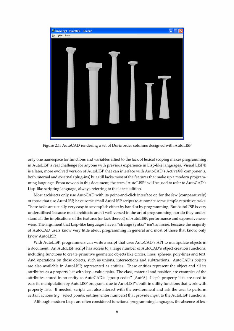
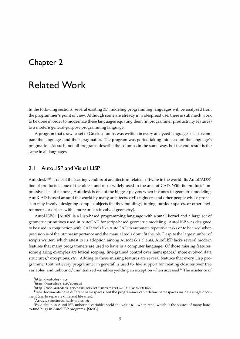
Figure 2.1: AutoCAD rendering a set of Doric order columns designed with AutoLISP
only one namespace for functions and variables allied to the lack of lexical scoping makes programmingin AutoLISP a real challenge for anyone with previous experience in Lisp-like languages. Visual LISP®is a later, more evolved version of AutoLISP that can interface with AutoCAD’s ActiveX® components,both internal and external (plug-ins) but still lacks most of the features that make up a modern program-ming language. From now on in this document, the term “AutoLISP” will be used to refer to AutoCAD’sLisp-like scripting language, always referring to the latest edition.
Most architects only use AutoCAD with its point-and-click interface or, for the few (comparatively)of those that use AutoLISP, have some small AutoLISP scripts to automate some simple repetitive tasks.These tasks are usually very easy to accomplish either by hand or by programming. But AutoLISP is veryunderutilised because most architects aren’t well versed in the art of programming, nor do they under-stand all the implications of the features (or lack thereof) of AutoLISP, performance and expressiveness-wise. The argument that Lisp-like languages have a “strange syntax” isn’t an issue, because the majorityof AutoCAD users know very little about programming in general and most of those that know, onlyknow AutoLISP.
With AutoLISP, programmers can write a script that uses AutoCAD’s API to manipulate objects ina document. An AutoLISP script has access to a large number of AutoCAD’s object creation functions,including functions to create primitive geometric objects like circles, lines, spheres, poly-lines and text.And operations on those objects, such as unions, intersections and subtractions. AutoCAD’s objectsare also available in AutoLISP, represented as entities. These entities represent the object and all itsattributes as a property list with key→value pairs. The class, material and position are examples of theattributes stored in an entity as AutoCAD’s “group codes” [Aut08]. Lisp’s property lists are used toease its manipulation by AutoLISP programs due to AutoLISP’s built-in utility functions that work withproperty lists. If needed, scripts can also interact with the environment and ask the user to performcertain actions (e.g. select points, entities, enter numbers) that provide input to the AutoLISP functions.
Although modern Lisps are often considered functional programming languages, the absence of lex-
6
ical scope [Sco00] in AutoLISP introduces many obstacles when writing higher-order functions7 due tothe possible name collision between the free variables in the function passed as argument and any vari-able in the execution control flow until that function is called (including variables from the definitionof the higher-order function), which can lead to very hard to find bugs. The “functions as arguments”8
higher-order functions can be written in AutoLISP with some name-mangling in their parameters andlocal variables’ identifiers. If there is no name-sharing between parameters of different functions, we canprogram this kind of higher-order functions in AutoLISP. This is a “quick hack,” and not really a solutionto avoid the problems mentioned, but can’t be guaranteed to work (especially when using other people’slibraries) and seriously degrades code readability. The same can be said for the “functions as return val-ues”9, with more obstacles: Due to AutoLISP’s dynamic scope and lack of closures, it is impossible for afunction to capture the bindings of its free variables, as it’s usual in most functional programming lan-guages. If this function is returned from another function then, when invoked, those free variables willeither be unbound or be bound to a possibly completely unrelated variable than the one the programmerwanted.
Another feature that most Lisp programmers will miss in AutoLISP is the macro system. Neitherhygienic [Cli91] nor non-hygienic [SG96] macros are available for creating language extensions. While,for programmers with background on Algol-descendant programming languages,10 macros aren’t es-sential, most Lisp programmers consider them11 fundamental features, due to being able to implementcompletely new control structures and change the “shape” of the language with a simple mechanism.
2.1.1 Primitives
In this section we describe the AutoCAD primitive objects, which can be created using AutoCAD’s com-mand line, AutoLISP, ActiveX and .NET scripting facilities.Lines There are various types of lines in AutoCAD. The simple Line is a line between two points, but
there are more general line objects, including Polylines, LightweightPolylines and MLines (multiplelines following the same path), all of which create two-dimensional lines. The LightweightPolylineis an optimized version of the Polyline object which, given a set of coordinates of the vertexes,creates a line between each vertex and the next. These lines are often used for creating paths forextruding 2D shapes. Additionally, one type of three-dimensional line is available, the 3DPolyline,which can be created with points that are not all in the same plane.
Curves In AutoCAD, we can create various kinds of curves. Open or closed. Arcs, Circles, Ellipsesand Splines are available. An Arc is defined by a center, a radius and a start and end angles. AnEllipse is defined by a center, the length of the major axis and the ratio between the two axis, whilethe Circle is an ellipse with a ratio of 1.0. The Spline12 is a particular type of curve which passesthrough N given points;
Meshes A mesh represents an object’s surface using planar facets. In AutoCAD, two types of meshesare available: The PolygonMesh and the more general Polyfacemesh. The PolygonMesh is a matrix ofM × N vertexes, which are the vertexes of the facets. The Polyfacemesh is more general, wherean array of vertexes is given and then an array of facet definitions is also provided. Each facet iscomposed of four of the given vertexes;
7Higher-order functions are functions that take functions as arguments and/or return functions as results. Thesefunctions are fundamental in functional programming to abstract common behaviour.
8Also known as the downward funarg (functional argument) problem. [Mos70]9The upward funarg problem.
10C, C++, Java, C#, etc.11Lisp macros, not to be confused with macros in a language like C, where macros are simple text replacements.12Splines in AutoCAD are quadratic or cubic NURBS curves.
7
Box A box is a parallelepiped which is defined by a central point (the center of the parallelepiped) andits three dimensions: length, width and height;
Cone A cone which is define by its center ⟨x, y, z⟩, its base radius (the base is centered at ⟨x, y, z − h2
⟩)and its height (h). Also available is an elliptical cone, which has an ellipse as a base and an extraargument: the minor radius;
Cylinder A cylinder is defined using the same parameters as a cone (center, radius and height), and hasan elliptical counterpart as well;
Extrusion An extrusion of a Region13 along a path. An optimized version is available when the path isa straight line, possibly having an angle different from π
2 radians with the region. Revolution ofa region has also an optimized case, where a region is revolved around a user-defined axis for agiven angle;
Sphere A sphere is centered around a given point and has a user-defined radius;
Torus A torus is an extrusion of a circle around a point, which yields a ring-like shape. The torus isdefined by its center, the radius of the torus (the distance from the center of the torus to its outeredge) and the tube radius (the radius of the extruded circle);
Wedge A wedge is half a parallelepiped, with triangles as its side facets. It is defined by a center point,its length, width and height.
Along with the primitives to create several 3D objects, there are some transformations available. Ob-jects can be rotated in space by providing an axis of rotation and an angle to rotate the objects. A Movemethod is available to move the objects in 3D space, as well as the ScaleEntity method which scales anentity equally in the X , Y and Z planes. For more controlled transformations, a TransformBy method isavailable, which receives a transformation matrix and applies the transformations described in it.
Also available are the 3D CSG operations, for union, intersection and difference of 3D solids. Allthese functions yield another 3D solid and the original solids can be deleted or kept for further uses,depending on the user’s choice.
In Fig. 2.1, the output of the AutoCAD Doric-order columns script can be seen. The pragmatic ofprogramming in AutoLISP (if any) is to just send the primitive commands to AutoCAD as can be seenin the definition of cut-cone which uses the command primitive.14 In this script every column is givena starting point and some parameters to control its shape and size as can be seen in Fig. 2.1. The box2function was defined in a way analogous to it, but using AutoCAD’s BOX primitive command.
2.1.2 Conclusions
Being the most used CAD program in the world, AutoCAD and its programmability features must betaken into account for this work. Despite showing its age, AutoLISP is still used by many groups of peo-ple with disparate programming skills, for automating all kinds of tasks in AutoCAD. Although widelyused, its potential is very underutilised. Many architects either don’t know it’s available or only use itby emulating what they would do manually, thereby automating some simple repetitive tasks. Besidesbeing a language without many features that most programmers take for granted, it is also shunned bymany programmers due to being Lisp-like. On the other hand, most AutoCAD-using professionals willprefer a Lisp-like language due to already being familiar with the syntax.
13A Region is a closed two-dimensional loop.14In Visual LISP there are wrapper functions for every AutoCAD ActiveX/COM method, but the primitive Au-
toCAD commands are still widely used.
8

(a) AutoLISP definitions
;; Load COM functions
(vl-load-com)
(defun erase-all () (command "._ERASE" "_All" ""))
(defun zoom-extents () (command "._ZOOM" "_Extents" ""))
;; Point-related utility functions
(setq xyz list)
(setq px car)
(setq py cadr)
(setq pz caddr)
(defun +xyz (p x y z)
(xyz (+ (px p) x)
(+ (py p) y)
(+ (pz p) z)))
(defun +z (p z) (+xyz p 0 0 z))
(defun box (origin width length height)
(command "._BOX" origin "_Length" length width height)
(entlast))
(defun box2 (origin destination)
(command "._BOX" origin destination)
(entlast))
(defun cylinder (base-center base-radius height)
(command "._CYLINDER" base-center base-radius height)
(entlast))
(defun cut-cone (base-center base-radius top-radius height)
(command "._CONE" base-center base-radius
"_Top" top-radius height)
(entlast))
(defun shaft (p height base-r top-r)
(cut-cone p base-r top-r height))
(defun capital (p height base-r top-r)
(cut-cone p base-r top-r height))
(defun abacus (p height length)
(box2 (+xyz p (/ length -2.0) (/ length -2.0) 0)
(+xyz p (/ length 2.0) (/ length 2.0) height)))
(defun doric-column (p
shaft-h shaft-base-r
capital-h capital-base-r
abacus-h abacus-l)
(shaft p shaft-h shaft-base-r capital-base-r)
(capital (+z p shaft-h) capital-h capital-base-r (/ abacus-l 2.0))
(abacus (+z p (+ shaft-h capital-h)) abacus-h abacus-l))
(erase-all)
(doric-column (xyz 0 0 0) 9 0.5 0.4 0.3 0.3 1.0)
(doric-column (xyz 3 0 0) 7 0.5 0.4 0.6 0.6 1.6)
(doric-column (xyz 6 0 0) 9 0.7 0.5 0.3 0.2 1.2)
(doric-column (xyz 9 0 0) 8 0.4 0.3 0.2 0.3 1.0)
(b) AutoLISP main program(erase-all)
(doric-column (xyz 0 0 0) 9 0.5 0.4 0.3 0.3 1.0)
(doric-column (xyz 3 0 0) 7 0.5 0.4 0.6 0.6 1.6)
(doric-column (xyz 6 0 0) 9 0.7 0.5 0.3 0.2 1.2)
(doric-column (xyz 9 0 0) 8 0.4 0.3 0.2 0.3 1.0)
(doric-column (xyz 12 0 0) 5 0.5 0.4 0.3 0.1 1.0)
(doric-column (xyz 15 0 0) 6 0.8 0.3 0.2 0.4 1.4)
(zoom-extents)
Listing 2.1: AutoLISP code for drawing Doric-order columns
2.2 Generative Modeling Language
The Generative Modeling Language (GML)15 is a simple stack-based language for describing 3D objects.Traditionally, lists of geometric primitives are used to model 3D objects. Instead, with a generative ap-proach [Ley01], geometric models are created by composing operations and the design becomes focusedon rules for transforming primitive objects instead of focusing on combining these primitives. Keepingtrack of only the necessary operations to model an object typically consumes much less space than stor-ing the results of that computation (for example, a mesh of triangles). As the processing power increases,it becomes easier to generate huge amounts of data on the fly, only when the data is needed.
Although initially based on Python,16 its authors decided to use Adobe®’s17 PostScript®18 as the corelanguage for GML because it’s much simpler to manipulate programmatically [Hav05]. Doing withoutmost typesetting and many of PostScript’s 2D operations, the GML is much simpler and very familiarto anyone familiar with its ancestor. GML extends the PostScript set of operations with several others,from vector algebra to the handling of polygons, including several conversions [Hav03]. This languageis not for the common architect, though. Being a postfix language, it’s not very easy to learn to someonewho is not familiarised with programming, in general, at least. Although very simple, postfix languagesare even less familiar to most programmers than Lisp-like languages. The main goal of GML is not to bejust a 3D modeling language per se, but to enable the building of higher-level tools for 3D modeling thatuse GML programs. These GML programs would be created by advanced users and used by all kinds
15http://www.generative-modeling.org/16http://python.org17http://adobe.com/18http://adobe.com/products/postscript
9
of users, from beginning to advanced, to facilitate some operations.With its twelve simple rules for evaluating programs, GML is very easily adopted by a programmer,
but not so easily by an architect. Because of the abstract nature of programming, a person that is notwell versed in abstract thinking may find it hard to read the program’s source code and know what itsoutput will be like. The forced abstract thinking allied to the need of maintaining state (in the program-mer’s mind) while reading the program definition, due to GML not being a functional language but animperative one, are two of the reasons this language is not very well suited for architects or designers todesign objects, although it could very well be used as a back-end for a tool that simplifies GML’s use.
(a) cut-cone utility item for the shaft and capitalColumns.Config begin
usereg
!top-r
!base-r
!height
material setcurrentmaterial
(0,-1,0) :base-r divisions circle
3 poly2doubleface
:base-r :top-r sub
:height 3 vector3 extrude
end
(b) Item for drawing an abacusColumns.Tools begin
usereg
!length
!height
!p
:length 2.0 div !l2
:length -2.0 div !l-2
:l-2 0 :l-2 vector3 :p add
:l2 0 :l2 vector3 :p add
3 quad
3 poly2doubleface
0 :height neg 3 vector3 extrude
end
(c) Item for drawing a Doric-order columnusereg
!a-l
!a-h
!c-b-r
!c-h
!s-b-r
!s-h
!p
:p :s-h :s-b-r :c-b-r shaft
0 :s-h neg 0 vector3
:p add :c-h :c-b-r :a-l 2.0 div capital
0 :s-h :c-h add neg 0 vector3
:p add :a-h :a-l abacus
(d) Item for drawing the row of columnsdeleteallmacros newmacro clear
Columns begin
(0,0,0) 9 0.5 0.4 0.3 0.3 1.0 column
(3,0,0) 7 0.5 0.4 0.6 0.6 1.6 column
(6,0,0) 9 0.7 0.5 0.3 0.2 1.2 column
(9,0,0) 8 0.4 0.3 0.2 0.3 1.0 column
(12,0,0) 5 0.5 0.4 0.3 0.1 1.0 column
(15,0,0) 6 0.8 0.3 0.2 0.4 1.4 column
end
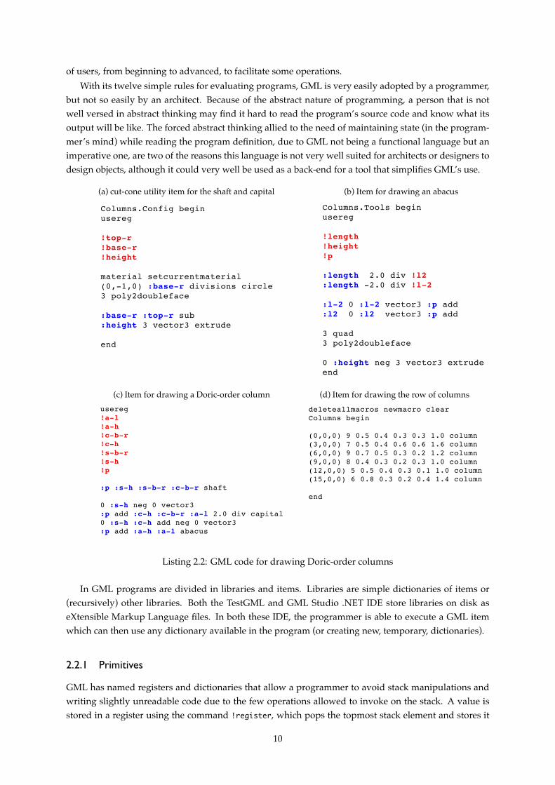
Listing 2.2: GML code for drawing Doric-order columns
In GML programs are divided in libraries and items. Libraries are simple dictionaries of items or(recursively) other libraries. Both the TestGML and GML Studio .NET IDE store libraries on disk aseXtensible Markup Language files. In both these IDE, the programmer is able to execute a GML itemwhich can then use any dictionary available in the program (or creating new, temporary, dictionaries).
2.2.1 Primitives
GML has named registers and dictionaries that allow a programmer to avoid stack manipulations andwriting slightly unreadable code due to the few operations allowed to invoke on the stack. A value isstored in a register using the command !register, which pops the topmost stack element and stores it
10
in the register named register. A register can then be read using :register, which pushes the valuestored in the register onto the stack. Not pictured are the shaft and capital items which simply invokethe cut-cone item.
2.2.2 Conclusions
Despite being an unusual programming language (due to being stack-based), GML can accomplish whatit’s designed to: Being a terse postfix programming language, which enables programmers t describeshapes with relative ease and without having to model every used mesh. By modeling the objects usinga high-level language, GML doesn’t need as much information as a mesh-based program to store theobjects.19 For example, while a mesh-based program would need to store every single vertex in orderto model a cube, in GML one just needs to store the high-level code that does the necessary operations:Create a quad (or a circle with four segments), turn it into a half-edge and then extrude it in the thirddimension. In spite of all these advantages, GML is still a hard to learn language for most programmers.Especially people with (relatively) few programming skills and who are used to just one language thathas a completely different syntax and is programmed in a completely different paradigm.
2.3 Programming LAnguage for Solid Modeling
The Programming LAnguage for Solid Modeling (PLaSM) is a functional programming language basedon IBM’s®20 FL [AWW91] programming language, which is a programming language that evolved fromJohn Backus’ FP programming language which introduced function-level programming to the program-ming world [Bac78]. It is a functional design language for geometric and solid parametric design devel-oped at the Roma Tre and La Sapienza universities [PS92, PPV95].
PLaSM takes on a programming approach to generative modeling, where geometric objects are gener-ated by composing functions using the language’s operators. It has a dimension-independent approachto geometric representation. PLaSM has support for higher-order functions in the FL style so, one wayto look at it, is to see PLaSM as a geometric domain-specific language (DSL) for FL. No free nesting ofscopes or pattern matching is allowed in PLaSM although an identifier can name any language object.Being a FL language successor, PLaSM shares much syntax with its ancestor. PLaSM also allows operatoroverloading and partially applied (curried) functions.
2.3.1 Language Primitives
PLaSM supports many elementary shapes through language primitives. Simples objects such as sim-plices, cuboids, cylinders and general polyhedra are available through simple primitive functions thathave the same properties as any user defined function. Along with primitive object creation, there aremany affine geometric transformations available for the programmer, including the always present scale,translation and rotation operations. These operations on coordinates can be arbitrarily composed andapplied to polyhedra. There is also a primitive operator that limits the scope of these operations to letthe programmer focus on local (object) coordinates when designing an object, and only when it is in-stantiated will the object be placed on the appropriate global (world) coordinates. PLaSM includes anoperator for creating 1-D polyhedra, as well as creating n-dimensional skeletons of objects. Anotherpowerful PLaSM primitive (which is a special case of the PRODUCT operator [BFPP93] (also available inPLaSM)) is the Intersection of extrusions operator (&&). With this operator it becomes very easy to generate
19But there is always a trade-off between memory and processing power.20http://ibm.com
11
a building from its plant and sections. The programmer simply defines the plant and section and thenuses the && operator, embedding the sections in the right coordinate subspaces. The && operator receivesa vector that describes how to embed each of the two objects in the coordinate subspace of the 3D re-sult. The operator then returns a binary function that receives both objects and returns the intersectionof their extrusions. Also available in PLaSM are generalized Boolean operations, making PLaSM thefirst dimension-independent implementation of Boolean operations [PVBP01]. PLaSM also has opera-tors for relative positioning of objects (ALIGN, TOP, BOTTOM, LEFT, etc. ). Of these, only the ALIGN operator isdimension-independent. The others are only suitable for relative positioning of 3D objects.
(a) PLaSM definitionsDEF coneFacets = 42;
DEF DoricColumn
(ShaftH, ShaftBR, CapitalH, CapitalBR,
AbacusH, AbacusL::IsRealPos) =
Shaft:<ShaftH, ShaftBR, CapitalBR>
TOP
Capital:<CapitalH, CapitalBR, AbacusL/2.0>
TOP
Abacus:<AbacusH, AbacusL>;
DEF Abacus(Height, Length::IsRealPos) =
CUBOID:<Length,Length,Height>;
DEF Capital(Height, BaseR, TopR::IsRealPos) =
CutConeZ:<Height, BaseR, TopR>;
DEF Shaft(Height, BaseR, TopR::IsRealPos) =
CutConeZ:<Height, BaseR, TopR>;
DEF CutConeZ(Height, BaseR, TopR::IsRealPos) =
TrunCone:<BaseR,TopR,Height>:coneFacets;
DEF Left3 = T:1:3;
DEF Columns = STRUCT:<
DoricColumn:<9, 0.5, 0.4, 0.3, 0.3, 1.0>,
Left3,
DoricColumn:<7, 0.5, 0.4, 0.6, 0.6, 1.6>,
Left3,
DoricColumn:<9, 0.7, 0.5, 0.3, 0.2, 1.2>,
Left3,
DoricColumn:<8, 0.4, 0.3, 0.2, 0.3, 1.0>,
Left3,
DoricColumn:<5, 0.5, 0.4, 0.3, 0.1, 1.0>,
Left3,
DoricColumn:<6, 0.8, 0.3, 0.2, 0.4, 1.4>>;
Columns;
(b) PLaSM main program
DEF coneFacets = 42;
DEF DoricColumn
(ShaftH, ShaftBR, CapitalH, CapitalBR,
AbacusH, AbacusL::IsRealPos) =
Shaft:<ShaftH, ShaftBR, CapitalBR>
TOP
Capital:<CapitalH, CapitalBR, AbacusL/2.0>
TOP
Abacus:<AbacusH, AbacusL>;
DEF Abacus(Height, Length::IsRealPos) =
CUBOID:<Length,Length,Height>;
DEF Capital(Height, BaseR, TopR::IsRealPos) =
CutConeZ:<Height, BaseR, TopR>;
DEF Shaft(Height, BaseR, TopR::IsRealPos) =
CutConeZ:<Height, BaseR, TopR>;
DEF CutConeZ(Height, BaseR, TopR::IsRealPos) =
TrunCone:<BaseR,TopR,Height>:coneFacets;
DEF Left3 = T:1:3;
DEF Columns = STRUCT:<
DoricColumn:<9, 0.5, 0.4, 0.3, 0.3, 1.0>,
Left3,
DoricColumn:<7, 0.5, 0.4, 0.6, 0.6, 1.6>,
Left3,
DoricColumn:<9, 0.7, 0.5, 0.3, 0.2, 1.2>,
Left3,
DoricColumn:<8, 0.4, 0.3, 0.2, 0.3, 1.0>,
Left3,
DoricColumn:<5, 0.5, 0.4, 0.3, 0.1, 1.0>,
Left3,
DoricColumn:<6, 0.8, 0.3, 0.2, 0.4, 1.4>>;
Columns;
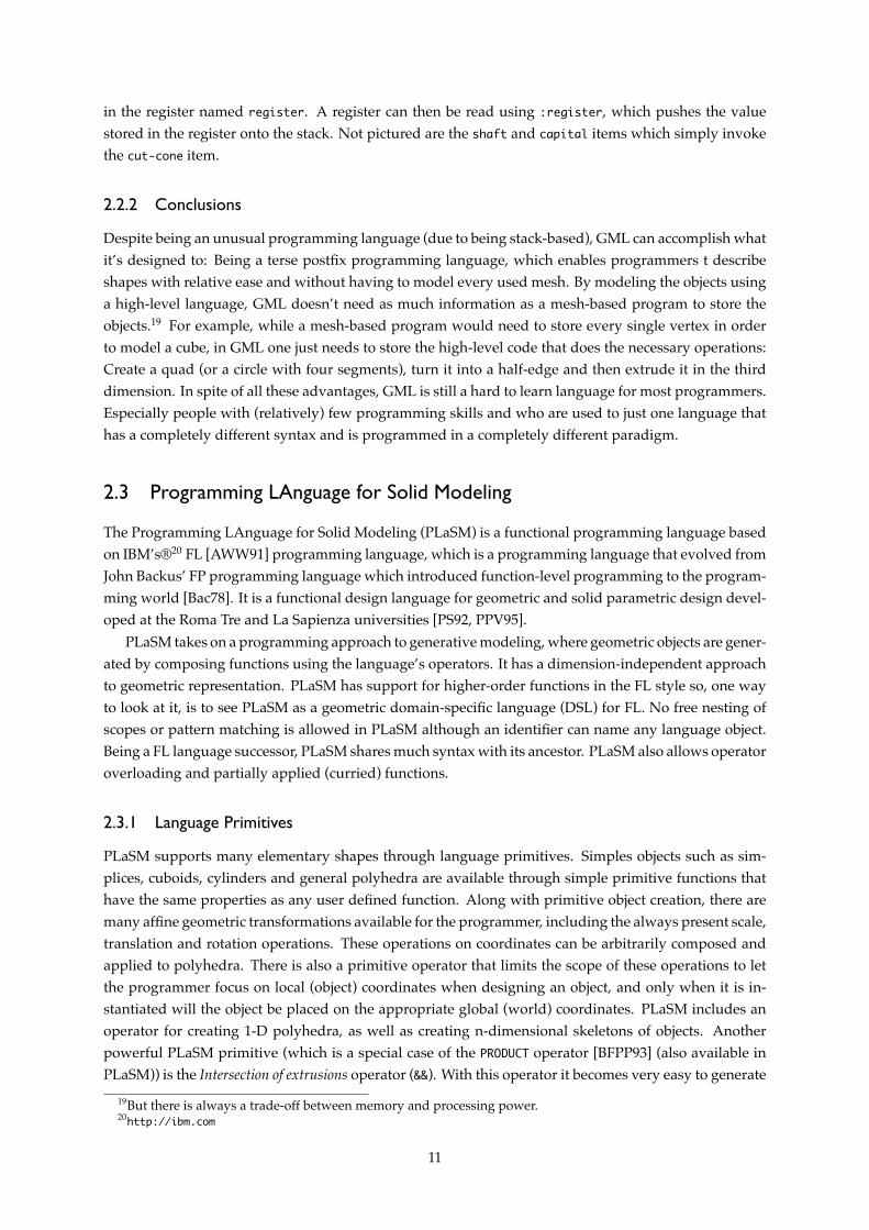
Listing 2.3: PLaSM code for drawing Doric-order columns
PLaSM’s Xplode IDE21 is a simple IDE that syntax highlights PLaSM programs for easy reading andserves as the interface for a PLaSM listener program. There is a VRML viewer (Fig. ??) included in theIDE package which allows the programmer to export the solids to a VRML file for later viewing. Thecolumns in the PLaSM program in Fig. 2.3 are built using the 3D positional operators rather than usinga reference point and translating it to create the capital and abacus of the column. As the definition ofthe Columns object just creates a function, the function must afterwards be invoked.
21http://www.plasm.net/tools/xplode_ide
12

2.3.2 Conclusions
Despite the long learning curve for anyone not familiar with the FP or FL languages, PLaSM is a veryexpressive 3D modeling language where one can design big, complex parametrized objects with relativeease and make any change to the parameters, having the result just a render away. The completely func-tional approach, although better for parallelism and closer to the mathematical foundations of geometry,is harder to grasp for most people that learned to program in an imperative language (e.g. C, Java, etc. ).But, by not having any imperative constructs, PLaSM may lose some audience among those who alreadyknew how to program imperatively.
2.4 POV-Ray
The Persistence of Vision Raytracer (POV-Ray)™22 is an open source ray-tracing program that grew outof David Buck’s hobby ray-tracer, DKBTrace [Per01]. With its large comprehensive library of objects,colors, textures, and many available special effects and rendering effects, POV-Ray is one of the mostwidely used ray-tracers around the world, and has a very large community 23 where users can find help.The IDE included in its distribution has many features and documentation that help anyone using POV-Ray’s scripting facilities.
2.4.1 Ray-Tracing
Ray-tracing is a method for generating digital images by simulating the path of light as it passes throughthe output image’s pixels, simulating the way photons travel in the real world. This technique is capableof generating images with a high degree of photo-realism, although it’s computationally very intensive.With this characteristic in mind, ray-tracing is mostly used for rendering images when off-line renderingis available, such as in the T.V. or movie industries. Infamous for its rendering times, ray-tracing wasn’teven considered for real-time rendering applications until recently [Muu95, PMS+05, DS07].
2.4.2 Scene Description Language
POV-Ray’s Scene Description Language (SDL) is a Turing-complete language that allows a programmerto describe the world in an efficient and readable way. The scene description language is a very basiclanguage with support for abstraction mechanisms (e.g. macros and functions). It’s mostly a declara-tive language, which means most of the objects are defined at one time in the program execution andaren’t modified afterwards. Although declarative, POV-Ray’s SDL has some facilities for iterating andmutating variables, e.g. for placing a building’s columns in a row or circle programmatically, insteadof manually defining every column needed (which would have to change if one was to, e.g. change thenumber of columns).
Every POV-Ray scene needs a camera and, at least, a light-source. After placing these two conceptson the scene, the programmer may use whatever primitives are available from POV-Ray or in any im-ported libraries. Several primitive finite and infinite objects are available “out-of-the-box,” as are morecomplex primitives like iso-surfaces and ways of combining objects, through Constructive Solid Geom-etry. Despite the power conferred to the programmer by the SDL, most complex models (e.g. realisticcharacters or complex man-made objects) in a scene are usually modeled using higher-level tools likethe open-source Blender 3D24 program and then exported to a format POV-Ray can use.
22http://povray.org23http://www.povray.org/community24http://blender.org
13
(a) POV-Ray definitions
#include "colors.inc"
camera { location <3, 17, 5> look_at (x*7.5+z*5) sky z }
light_source { <0, 15, 5> rgb White*5 }
#declare shaft_pigment =
texture {
pigment { color Gray30 }
}
#declare capital_pigment = shaft_pigment
#declare abacus_pigment = shaft_pigment
#macro shaft(p, height, baseR, topR)
cone { p, baseR, p + height*z, topR
texture { shaft_pigment } }
#end
#macro capital(p height baseR topR)
cone { p, baseR, p + height*z, topR
texture { capital_pigment} }
#end
#macro abacus(p, height, length)
box { p - <length/2.0, length/2.0, 0>,
p + <length/2.0, length/2.0, height>
texture { abacus_pigment } }
#end
#macro doricColumn(p,
shaftH, shaftBaseR,
capitalH, capitalBaseR,
abacusH, abacusL)
shaft(p, shaftH, shaftBaseR, capitalBaseR)
capital(p + shaftH*z, capitalH, capitalBaseR, abacusL/2.0)
abacus(p + (shaftH+capitalH)*z, abacusH, abacusL)
#end
#debug "columns..."
doricColumn( 0, 9, 0.5, 0.4, 0.3, 0.3, 1.0)
doricColumn(< 3,0,0>, 7, 0.5, 0.4, 0.6, 0.6, 1.6)
doricColumn(< 6,0,0>, 9, 0.7, 0.5, 0.3, 0.2, 1.2)
doricColumn(< 9,0,0>, 8, 0.4, 0.3, 0.2, 0.3, 1.0)
doricColumn(<12,0,0>, 5, 0.5, 0.4, 0.3, 0.1, 1.0)
doricColumn(<15,0,0>, 6, 0.8, 0.3, 0.2, 0.4, 1.4)
(b) POV-Ray main program
#include "colors.inc"
camera { location <3, 17, 5> look_at (x*7.5+z*5) sky z }
light_source { <0, 15, 5> rgb White*5 }
#declare shaft_pigment =
texture {
pigment { color Gray30 }
}
#declare capital_pigment = shaft_pigment
#declare abacus_pigment = shaft_pigment
#macro shaft(p, height, baseR, topR)
cone { p, baseR, p + height*z, topR
texture { shaft_pigment } }
#end
#macro capital(p height baseR topR)
cone { p, baseR, p + height*z, topR
texture { capital_pigment} }
#end
#macro abacus(p, height, length)
box { p - <length/2.0, length/2.0, 0>,
p + <length/2.0, length/2.0, height>
texture { abacus_pigment } }
#end
#macro doricColumn(p,
shaftH, shaftBaseR,
capitalH, capitalBaseR,
abacusH, abacusL)
shaft(p, shaftH, shaftBaseR, capitalBaseR)
capital(p + shaftH*z, capitalH, capitalBaseR, abacusL/2.0)
abacus(p + (shaftH+capitalH)*z, abacusH, abacusL)
#end
#debug "columns..."
doricColumn( 0, 9, 0.5, 0.4, 0.3, 0.3, 1.0)
doricColumn(< 3,0,0>, 7, 0.5, 0.4, 0.6, 0.6, 1.6)
doricColumn(< 6,0,0>, 9, 0.7, 0.5, 0.3, 0.2, 1.2)
doricColumn(< 9,0,0>, 8, 0.4, 0.3, 0.2, 0.3, 1.0)
doricColumn(<12,0,0>, 5, 0.5, 0.4, 0.3, 0.1, 1.0)
doricColumn(<15,0,0>, 6, 0.8, 0.3, 0.2, 0.4, 1.4)
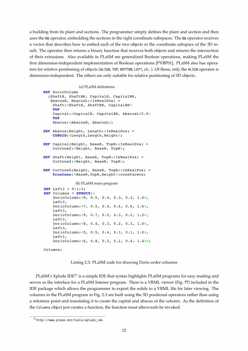
Listing 2.4: POV-Ray code for drawing Doric-order columns
The POV-Ray version of the program (Fig. 2.4) consists of macros for the smaller components of thecolumns which will then be put in place by the doricColumn macro by creating the objects appropriatelytranslated in the z coordinate. Not pictured is the code to place the camera and light sources in the scenenor the code defining the shaft, capital and abacus’ pigment as a light gray as that code isn’t directlyinvolved in the objects’ modeling.
2.4.3 Conclusions
POV-Ray is a very good ray-tracer with a very helpful community built around it. It is capable of gen-erating very high-quality photo-realistic renderings with small scripts due to its big high-quality objectand texture library. The language in itself is declarative, although some support for imperative pro-gramming is present, in the form of macros. It is relatively easy for someone with some programmingexperience to start scripting POV-Ray, and start modeling parametrized objects programmatically withease. The higher-order functions and capabilities for abstraction may be missed by some programmers,though.
2.5 X3D
X3D is a run-time architecture and file format to represent 3D scenes. It is a royalty-free open stan-dard ratified by the ISO committee [ISO04], with various standardized encodings (e.g. XML and Classic
14
VRML [ISO05]) and bindings [ISO06] for several languages (e.g. ECMAScript and Java). X3D providesa system for the storage, retrieval and playback of graphics content embedded in an application. As thesuccessor of VRML [ISO96], X3D is mainly fueled by web development and the possibility of embedding3D content in a webpage in straight HTML [BEJZ09], which was one drawback the old VRML standardhad.
While its predecessor – VRML – was dismissed as being “a technology in search of a use” [Shi98],X3D has already been implemented as a distribution format in several 3D authoring programs, suchas AutoCAD, Revit and 3dsMax, among others. Multi-platform support also exists and a centralizedrepository of information about X3D is available from the Web3D Consortium.25
X3D has a rich set of general parametrizable primitives that can be used for a variety of purposesin engineering, scientific visualization, CAD and architecture, and more. X3D was designed to be com-patible with the legacy VRML standard and very extensible. Developed taking into account the COL-LADA [AP07] standard for 3D representation, X3D is designed for real-time communication of 3D datawhile maximizing interoperability among different tools.
2.5.1 The Format
X3D is a file format with two simple encodings: legacy VRML and XML. The VRML encoding exists forbackwards compatibility as many VRML 2 worlds can be used as X3D with only minor changes [Web05].The XML encoding is available to ease interaction with many different tools and to be able to exploit themany existing tools and libraries to read, write and validate the documents.
There are several profiles available for X3D, which allows for several levels of support. These rangefrom the simpler Interchange profile to Full X3D:
Core The absolute minimal definitions X3D requires;
Interchange The basic profile for the interchange of information between applications. It supports ge-ometry, texturing, basic lighting and animation primitives;
Interactive A superset of the Interchange profile which adds basic interaction with a 3D environmentthrough sensor nodes, enhanced timing support and additional lighting primitives;
Immersive Supports everything in the Interactive profile and adds audio support, collisions, fog andscripting;
Full Includes all defined nodes, including NURBS,26 H-Anim27 and GeoSpatial nodes.28
Two additional profiles exist: The MPEG-4 Interactive profile, which is a small footprint versionof the Interactive profile designed for memory and processor-challenged devices, and the CDF (CADDistillation Format) which is in development in order to enable the translation of CAD data to an openformat for publishing.
A X3D world is defined as a sequence of statements. The first of these is the Header statement,followed by a PROFILE statement. These statements are encoding dependent and contain some necessaryinformation, such as the standard being used, along with its version, the character encoding being usedand some optional comments for the file. This Header statement will always store its information in ahuman-readable format. The PROFILE statement will declare which of the 7 available profiles [ISO08a]
25http://web3d.org/26Non Uniform Rational Basis Spline — A mathematical model for representing curves and surfaces27Humanoid animation (http://www.h-anim.org/)28To associate real-world locations to elements in the X3D world
15

will be used. Additional components, which are not in the selected profile, can be used by declaringthem with a COMPONENT statement. Metadata about the world being defined can also be provided with aMETA statement. The ability to define new node types is given by the PROTO and EXTERNPROTO statements.These statements assign a name to a new node type along with the declaration of its interface. The PROTOstatement defines the new node type functionality inline while the implementation of the EXTERNPROTO’snode type is implemented externally. As it is designed to have an interactivity component, routes canbe defined to specify connections between fields of different nodes, using the ROUTE statement.
The X3D Core profile has all the above nodes and includes features for the grouping of nodes, con-trolling the rendering and lighting of the world, constructing shapes and controlling their texture, usinginterpolated functions for parameters, navigation and some environmental effects. The Interactive pro-file adds interactivity to the worlds through key devices and pointing devices. The Immersive profileadds more interactivity, augmenting the control of the various input devices and also includes scriptingsupport for X3D. From one profile to the next existing nodes may be enhanced by adding some fieldswhich raise its Support level, which ranges from 1 to 5, although some components stop at a level lessthan 5.
2.5.2 Primitives
X3D provides several primitives for primitive 3D geometric shapes:
Box A parallelepiped box that is centered at ⟨0, 0, 0⟩ and has a length, width and height;
Cone A cone which is centered at ⟨0, 0, 0⟩ and is defined by a radius (at the bottom of the cylinder) anda height. The side of the cone and the bottom cap may be specified as inexistent for rendering andcollision detection;
Cylinder A cylinder which is centered at ⟨0, 0, 0⟩ defined by a radius and height. The top and bottomcaps, as well as the side of the cylinder may be specified as inexistent;
ElevationGrid Specifies a uniform rectangular grid of points with varying height in the Y = 0 plane.The number of elements is configurable (in both dimensions), as well as the spacing between el-ements for each dimension. The normal for each of the grid’s quadrilateral (or even each vertex)can be specified, if the default values are not what the user pretends;
Extrusion Extrudes a two dimensional cross-section along a three-dimensional spine. The cross-sectioncan be scales and rotated at each spine point. The sides, the begin cap and the end cap can also bespecified as inexistent;
IndexedFaceSet A 3D shaped formed by constructing faces with the vertexes given. A user supplies alist of vertexes and a list of vertex indexes (into the first list) that will form the solid’s faces;
Sphere A sphere that is defined by a radius and centered at ⟨0, 0, 0⟩.
Additionally, there are nodes to group sets of nodes together for use as arguments, or for optimiza-tions and transformations. A translation, rotation or scale transformation is always executed to a set ofnodes and in regard to a certain point. The translation is absolute, with a translation vector. The rota-tion may displace the center instead of rotating the objects with the point ⟨0, 0, 0⟩ as center. The scalecan also have the center changed and can be non-uniform in among the different dimensions. The threeoperations can be combined in a single node. In this case, the operations are always performed in thefollowing order: scale → rotation → translation.
16

Like the PDF file format [ISO08b], X3D has no control structures per se. The interpolators can beused in some situations where one would use control structures, but not always. Normally the designerwould model in a high-level program (e.g. a Java program that uses X3D’s Java bindings or a point-and-click program like Autodesk’s Maya or Blender Foundation’s Blender 3D) and then export the model toX3D.
X3D is aimed at being written by automated tools, and lacks high-level primitives to be practical fora human to model objects in it. Most of X3D’s usage comes from tools which export models to X3D forweb-based viewing and portability among different tools. As such, the X3D code for the Doric-ordercolumns’ model is a rather large file which we decided not to include in this document. Due to the lackof primitives, the columns’ model had to be created using IndexedFaceSet and sets of points to build thefaces of the columns. However, X3D is a language which can be used as a back-end for VisualScheme,allowing the programmer to export models to a variety of programs which support X3D. As an example,Listing 2.5 contains a snippet of the program to model the Doric-order columns.
Shape { # triangle meshappearance Appearance {
material Material {ambientIntensity 0diffuseColor 1 1 1specularColor 0 0 0emissiveColor 0 0 0shininess 1transparency 0}
} # appearancegeometry IndexedFaceSet { # triangle mesh
ccw TRUEconvex TRUEsolid FALSEcoordIndex [
26, 1, 0, -1, # triangle 026, 0, 25, -1,27, 2, 1, -1,27, 1, 26, -1,# More indexed faces74, 48, 73, -1
] # 96 trianglescoord Coordinate { point [
12.5 0 0, # coord point 012.48416328430176 0.1248452961444855 0,12.43434238433838 0.2476829886436462 0,12.3553524017334 0.3517448604106903 0,# More coordinates12.30000019073486 0 5
] } # 74 coord points} # geometry
} # triangle mesh
Listing 2.5: Part of the X3d code for drawing Doric-order columns
2.5.3 Conclusions
X3D is a simple, web oriented 3D file format, designed for embedding 3D content in web-pages andpublishing content for use in any program that implements this standard. The XML encoding facilitatesintegration in existing tools while the legacy VRML encoding helps people who write X3D directly. De-spite some criticisms, The X3D standard is getting widely adopted, from 3D modeling programs to webbrowsers to GIS29 programs. There is a lack of CSG functions, which makes it better suited for modelingsome kinds of objects with the help of higher-level tools which will do any necessary calculations andconvert the CSG constructs into lower-level primitives. There are very few primitives which can then becombined to create much more complex objects.
29Geographic Information System
17
2.6 Grasshopper 3D
Grasshopper 3D is a plug-in for visual programming built on top of the Rhinoceros 3D modeling tool(Rhino). Rhino is a 3D modeling program which widely used in many design fields, such as marineand jewelry design, CAD/CAM and rapid prototyping. It’s primitives are based on NURBS and it hasseveral rendering options. Rhino is also used to convert between modeling program’s file formats, sinceit can import from and export to a wide variety of formats. [PI09]
Like many other current CAD/CAM programs, Rhino represents free-form shapes as NURBS, whichare a mathematical model of a shape, instead of using meshes, which are a collection of points which formadjacent flat triangles. By using NURBS instead of meshes, Rhino is more precise and easily handlestransformations, allowing the user to specify how much accuracy is needed for a given rendering (for asketch, an architect doesn’t need the same accuracy in the drawing as for a photo-realistic rendering).
Being built on top of Rhino, Grasshopper leverages on all its primitives and operations, including theability to use other Rhino plug-ins and extensions.
Grasshopper’s programs are designed using a “boxes and arrows” model. Boxes represent primitivesor operations and the arrows connect a box’s output to another box’s input. The inputs may also be fixed,using several widgets (including sliders and textual input), instead of deriving from another operation’sresults.
Grasshopper’s block library contains blocks for primitives and operations from Rhino, which areavailable as Grasshopper blocks. These blocks can then be linked with each other, with the possibility ofusing the same output in several inputs.
Being based on a “boxes and arrows” model, Grasshopper makes it easy for anyone who knows theoperations to start building a parameterized 3D model of an object. Instead of working on a 3D modelusing irreversible commands and storing the output of these commands using meshes, Grasshopperstores the sequence of operations needed to model the object and, when needed, sends the needed com-mands to Rhino. This implies that, when a change is made to the 3D model (by changing a connectionor adding/removing boxes), the 3D model can be easily regenerated by Grasshopper, by sending thenecessary commands to Rhino.
Grasshopper lacks any mechanism for block abstraction in its programs. Programmers work aroundthis by drawing delimiters over sets of boxes and inserting text in the model definition, but these haveno semantic meaning for the program, which makes it easy to get these annotations out of sync withthe program. Besides not being able to abstract, there is no equivalent, in Grasshopper, to higher-orderfunctions. Because of this, a programmer cannot easily experiment with transformation blocks in caseswhere a block iterates through a list of points. For example, the existence of a “higher-order-block” (ablock which could receive other blocks as arguments) would enable the creation of said block, easilychanging the operation performed by altering the corresponding connection.
Due to this lack of block abstractions, Grasshopper is less than adequate for the design of extensive,complex 3D models. There are blocks which can be programmed using C# or VB.NET, which can lever-age Microsoft’s .NET framework and any available libraries. But these blocks are simply a way to escapethe visual programming paradigm, which allows a programmer to overcome the adversities which arisefrom this paradigm. If a programmer wants to abstract a set of blocks, the only way to do it is to repli-cate the set of blocks’ operations in a single C# or VB.NET block, which also increments the complexityand requires more low-level knowledge while, at the same time, diverging from the visual program-ming paradigm. At the same time, abstraction using .NET blocks is a black box which can make readingprograms much more difficult, depending on what operations that block is performing.
Small Grasshopper programs are easily understood by virtue of the visual nature of the connectionsbetween boxes. But as complexity grows, programs get considerably confusing to the point that, even
18
for a small program, the programmer may have difficulty in remembering the corresponding betweenparts of the program and parts of the model. Although this happens also in text-based programminglanguages, this difficulty is aggravated, in Grasshopper, due to the lack of abstraction, which forces theprogrammer to remember a big part of the program in order to make any changes in the establishedconnections.
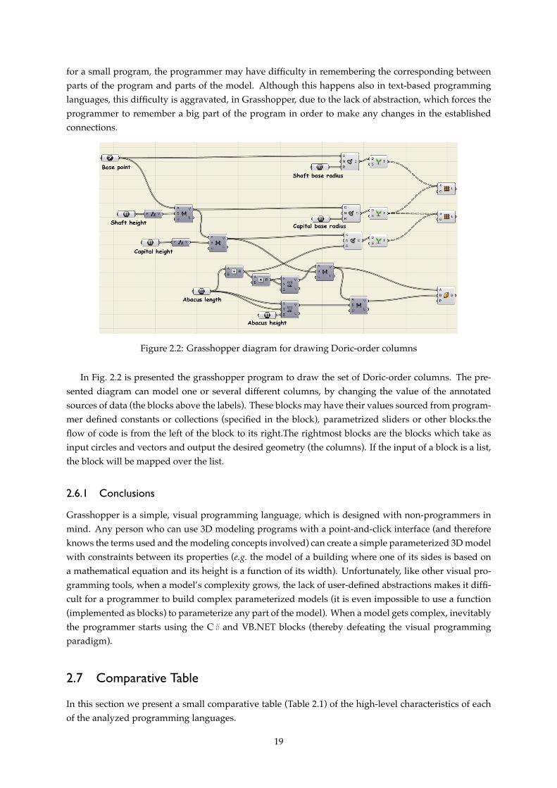
Figure 2.2: Grasshopper diagram for drawing Doric-order columns
In Fig. 2.2 is presented the grasshopper program to draw the set of Doric-order columns. The pre-sented diagram can model one or several different columns, by changing the value of the annotatedsources of data (the blocks above the labels). These blocks may have their values sourced from program-mer defined constants or collections (specified in the block), parametrized sliders or other blocks.theflow of code is from the left of the block to its right.The rightmost blocks are the blocks which take asinput circles and vectors and output the desired geometry (the columns). If the input of a block is a list,the block will be mapped over the list.
2.6.1 Conclusions
Grasshopper is a simple, visual programming language, which is designed with non-programmers inmind. Any person who can use 3D modeling programs with a point-and-click interface (and thereforeknows the terms used and the modeling concepts involved) can create a simple parameterized 3D modelwith constraints between its properties (e.g. the model of a building where one of its sides is based ona mathematical equation and its height is a function of its width). Unfortunately, like other visual pro-gramming tools, when a model’s complexity grows, the lack of user-defined abstractions makes it diffi-cult for a programmer to build complex parameterized models (it is even impossible to use a function(implemented as blocks) to parameterize any part of the model). When a model gets complex, inevitablythe programmer starts using the C# and VB.NET blocks (thereby defeating the visual programmingparadigm).
2.7 Comparative Table
In this section we present a small comparative table (Table 2.1) of the high-level characteristics of eachof the analyzed programming languages.
19
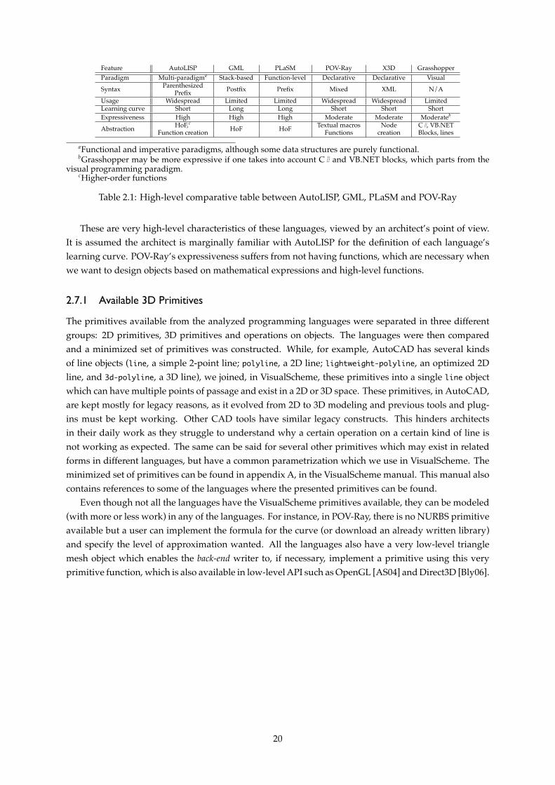
Feature AutoLISP GML PLaSM POV-Ray X3D GrasshopperParadigm Multi-paradigma Stack-based Function-level Declarative Declarative VisualSyntax Parenthesized Postfix Prefix Mixed XML N/APrefixUsage Widespread Limited Limited Widespread Widespread LimitedLearning curve Short Long Long Short Short ShortExpressiveness High High High Moderate Moderate Moderateb
Abstraction HoF,c HoF HoF Textual macros Node C#, VB.NETFunction creation Functions creation Blocks, lines
aFunctional and imperative paradigms, although some data structures are purely functional.bGrasshopper may be more expressive if one takes into account C# and VB.NET blocks, which parts from the
visual programming paradigm.cHigher-order functions
Table 2.1: High-level comparative table between AutoLISP, GML, PLaSM and POV-Ray
These are very high-level characteristics of these languages, viewed by an architect’s point of view.It is assumed the architect is marginally familiar with AutoLISP for the definition of each language’slearning curve. POV-Ray’s expressiveness suffers from not having functions, which are necessary whenwe want to design objects based on mathematical expressions and high-level functions.
2.7.1 Available 3D Primitives
The primitives available from the analyzed programming languages were separated in three differentgroups: 2D primitives, 3D primitives and operations on objects. The languages were then comparedand a minimized set of primitives was constructed. While, for example, AutoCAD has several kindsof line objects (line, a simple 2-point line; polyline, a 2D line; lightweight-polyline, an optimized 2Dline, and 3d-polyline, a 3D line), we joined, in VisualScheme, these primitives into a single line objectwhich can have multiple points of passage and exist in a 2D or 3D space. These primitives, in AutoCAD,are kept mostly for legacy reasons, as it evolved from 2D to 3D modeling and previous tools and plug-ins must be kept working. Other CAD tools have similar legacy constructs. This hinders architectsin their daily work as they struggle to understand why a certain operation on a certain kind of line isnot working as expected. The same can be said for several other primitives which may exist in relatedforms in different languages, but have a common parametrization which we use in VisualScheme. Theminimized set of primitives can be found in appendix A, in the VisualScheme manual. This manual alsocontains references to some of the languages where the presented primitives can be found.
Even though not all the languages have the VisualScheme primitives available, they can be modeled(with more or less work) in any of the languages. For instance, in POV-Ray, there is no NURBS primitiveavailable but a user can implement the formula for the curve (or download an already written library)and specify the level of approximation wanted. All the languages also have a very low-level trianglemesh object which enables the back-end writer to, if necessary, implement a primitive using this veryprimitive function, which is also available in low-level API such as OpenGL [AS04] and Direct3D [Bly06].
20
Chapter 3
Development Stages
In the first part of this work, several 3D modeling languages were studied and their features were com-pared to establish a starting point for our development.
This chapter presents the several development stages this project had. Its development was dividedin four main stages: Tool survey, language implementation, primitive object selection, and evaluation.The first two were started in parallel. After surveying the existing tools, the primitive selection wasstarted. The language will be continually developed, even after the work related to this thesis has ended.Throughout all the development stages, input was collected from architects and architecture students,in order to assess their difficulties and requirements when using the language. A case-study was alsodevised, using an iconic building from the city of Lisbon, which has a regular structure and was designedfrom scratch using CAD tools [Mol99]. This case-study also served as a comparative study with othertechnologies.
3.1 Tool Survey
Since the main goal of this project is to define a functional domain specific language for 3D modeling, onehas to survey the available options (presented in chapter 2), analyzing their pros and cons. By surveyingwhat is already available we have a point of reference so we can compare languages.
These tools were chosen to represent a wide variety of approaches to 3D modeling: imperative,declarative, functional and function-level programming languages, as well as visual programming lan-guages. By analyzing several different approaches to the same problem, several ideas can be extractedfrom each of them to improve the final work. A basic set of primitives can also be derived from theintersection of these languages.
By knowing how 3D models are designed in existing languages, we can also create a batch of testsfor our language.
3.2 Language Implementation
After surveying a set of languages and possible back-ends, the implementation of the language couldstart. Using what we learned from each of them, we chose the one that best suited our goals and whichcould be used for testing with end-users (as described in chapter 4).
After a first proof-of-concept language implementation, which included communication between theprogram used and our front-end but was too much low-level, a higher-level prototype was implementedand tested. The first implementation included a mechanism to emit low-level AutoCAD commands,
21
which provide access to every AutoCAD function that is available from the command-line (and fromAutoLISP). This mechanism was also ported to the new version as a back-end-specific feature, which isonly available when using AutoCAD as a back-end.1 The newer version controlled AutoCAD using morehigh-level communication protocols (ActiveX and COM), which improved its speed and allowed morecontrol on the generated objects.
Optimizations are also possible at back-end level, by taking into account the whole object. A back-endcan have an optimization pass where the tree defining the 3D model (which contains primitive objectsand operations) is minimized and expensive operations (or sets thereof) are substituted with more effi-cient operations for that specific back-end, while yielding the same results.
3.3 Primitive Object Selection
To build the basis of the language, it is crucial to select and implement a set of primitive objects andoperations.
This set of selected primitives (presented in appendix A)is comprised of basic solid primitives (e.g. spheres,boxes, cylinders), powerful lower-level objects (e.g. triangular meshes, height-fields), operations on ob-jects (e.g. translations, rotations, scales) and operations on sets of solids (e.g. unions, intersections, sub-tractions).
The primitive objects and operations were carefully chosen in order to ensure that every object whichis possible to model in one of the analyzed languages, is also possible to model in our language. Refer-ences were made in the manual in order to track the equivalences between VisualScheme’s primitivesand operations to the ones present in other modeling systems.
The selected 3D primitives and operations are described in appendix A, along with references to otherlanguages where that primitive or operation is available. These primitives were chosen by taking intoaccount what is available in other modeling systems and compacting the set of primitives whenever twoof them overlapped.
3.4 Evaluation
Feedback was collected from several students and the resulting knowledge was then incorporated inour design of the language and its primitives. This feedback was collected both directly, by providingthe students with a test version of VisualScheme, or indirectly, by analyzing frequent mistakes studentsmade in projects and exams (as can be seen in chapter 5).
Feedback is invaluable for the development of a programming language. It allowed us to detectwrong assumptions made initially and where the most common programming mistakes were beingmade, and helped us to better understand the students’ way of thinking.
The case study of the Gare do Oriente 3D model also served as a valuable resource when comparinga textual programming based approach to a visual programming one (Grasshopper).
1The core language itself is back-end neutral but specific back-ends can supply additional features.
22
Chapter 4
VisualScheme
The objective of this work is to create a domain specific language (DSL) for 3D modeling to enable ar-chitects to design buildings in a programmatic way, thereby reducing the amount of work needed toexperiment with different and elaborated shapes and allowing the programmatic modeling of 3D ob-jects.
The language created is an internal domain specific language based on Scheme. It provides several3D solid creating primitives, as well as operations on these objects.
VisualScheme programs are created by composing primitives and operations, creating a tree structurewith primitives on its leaves and operations as the branches. Several library functions are availablefor the programmer to use, e.g. functions to iterate over sequences of points, generating them usinginterpolation, and coordinate transformation.
After building the model tree, it is passed to the back-end, which will convert it to the sequence of com-mands needed to generate the same model in the worker program, sending the commands afterwards. Themodel is, generally, worker programindependent. The back-endmay expose some worker programspecificfunctions to the user which may break this independence but provide functions only available in thatworker program.
In the following sections, we present the architecture of VisualScheme and its AutoCAD back-end, aswell as some examples of possible extensions to VisualScheme which can be provided by library writers.
4.1 A Domain Specific Language
A domain specific language (DSL) is a language tailored for solving problems in a certain domain. Whilea general-purpose programming language (GPL) focuses on generality, allowing the programmer tosolve any problem, a DSL is focused in a single domain, trading the generality for expressiveness intheir domain. With this compromise, DSL programs are often shorter than their counterparts written ingeneral-purpose programming languages.
Several DSL are currently in mainstream use like GraphViz1 (for graph layout), SQL [ISO08c] (forinteracting with databases) and the languages we analyzed in chapter 2, like POV-Ray and GML, whichare oriented for 3D modeling.
DSL are advantageous due to a number of factors. For example [MHS05]:
• Appropriate domain-specific notations are, usually, more accessible in a DSL than they are in aGPL, due to significant investment in tailoring the language to that domain. These notations aredirectly related to the productivity improvement associated with DSL.;
1http://graphviz.org
23
• Domain-specific constructs are available in most DSL in order to abstract as much as possible. Beinga DSL, several abstractions which may be impossible to do using a GPL and a library may be built;
• A DSL also offers the possibility of easier analysis, verification, optimization, parallelization andtransformation of its programs. As it is, normally, much simpler than a GPL, where some analysisand optimizations are impossible to do;
VisualScheme is, in itself, a domain specific language for CAD built on top of the Scheme GPL, i.e. itretains Scheme’s characteristics while adding the CAD functionality on top of it.
4.2 Why Scheme?
Our primary goals for the designed language were:
• It should be simple, familiar, with a short learning curve;
• It should not depend on the worker program;
• It should be “fast enough”.
A Familiar Language
Because AutoLISP’s users are already familiar with Lisp-like programming languages, another Lisp-like programming language such as Scheme can attract them, since it has the syntax, semantics andmany of the features they already know how to use.2 Additionally, programs can be built on top of amodern programming language with many new facilities and powerful constructs for writing readable,compact code and protecting against certain kinds of bugs which plague AutoLISP programs. A Lisp-like language’s learning curve will be much shorter than another language with a much more evolvedsyntax, at least for AutoLISP programmers. Taking all this into account, Scheme was chosen as a modernLisp-like language, as our language of choice for parametric geometric modeling in the XXI century.
A Simple and Functional Language
Since Visual LISP is already built into AutoCAD and used around the world, it was decided to use a Lisp-like language for the 3D modeling language that will be designed, so as to gather the largest audiencepossible. As a Lisp dialect, the Scheme language shares much of its simple syntax: The program is writtenin S-Expressions3, which are then evaluated by the interpreter or compiled and executed. Scheme is alsoan actively developed programming language with a continually revised specification4 [SDF+07].
Scheme is also known for being a very simple language: the latest widely implemented standard(R5RS [KCR98]) had only 50 pages. By emphasizing the evaluation of expressions (as opposed to theexecution of commands), supporting recursion, having higher-order functions and performing tail-calloptimization (among other things), Scheme can be considered one of the most widely used functionalprogramming languages around the world.
Despite being a functional language, Scheme allows for side-effects, trading the “purely functionallanguage” classification for the ability to use multiple paradigms, which makes Scheme a good teachinglanguage (as can be seen by the success of books like [ASS96] and the TeachScheme! project [FFFK03]).
2An additional compatibility layer was implemented to make available a full AutoLISP interpreter, to run legacyscripts.
3An S-Expression is either an atom (e.g. a number, a symbol, a string) or a pair (cons) of S-Expressions4The last Scheme standard was ratified in 2007
24
For our design language’s first implementation, PLT Scheme5 was chosen as the base Scheme imple-mentation due to being one of the most actively developed Scheme compilers available, to its easy toreach and helpful community and its companion IDE, DrScheme6, which is oriented for a pedagogicalteaching of the language as well as its everyday use by an experienced programmer [FCF+02].
Worker Program Independent
The high-level language must be independent of the worker program. It should not be important for theprogrammer to know if the worker program is a CAD program, a 3D plotter, a simple visualizer, a flat fileor a web-browser. Scheme does not depend on the worker program(unlike AutoLISP, which can only beused with AutoCAD). VisualScheme is divided in a back-end and a front-end, and the back-end is furtherdivided in a lower back-end and a upper back-end. This lower back-end provides some Scheme functions tomake the bridge between the Scheme process and the worker program, and the upper back-end maps theprimitives of the language defined in this work into the worker program, using the functions defined in thelower back-end(being therefore, independent of the worker program). This is equivalent to using a machine-independent intermediate language when analysing and optimizing a program, before generating nativecode, as many modern compilers do [Lat02].
A Fast Language Implementation
Due to the sheer amount of data generated and operations executed when modeling a complex 3D object,the implemented language must not be a performance bottleneck. With a bottleneck in the interpreter orcompiler, the resulting language would end up being unusable, because the ratio of the script executiontime and the rendering would be high. If the language has a longer learning curve than simple tools likeAutoCAD’s basic drawing features, the programs would be used mostly for designing very complexobjects, that would be (almost) impossible to design by using the non-automated AutoCAD drawingtools. This is especially significant because render times for drafts are practically instantaneous.7
By using an actively developed optimizing Scheme compiler (and just-in-time compiler and opti-mizer [FFS08]) with a very helpful community, the performance problem is easily addressed by takingit into account when implementing the upper back-end and the front-end.8
4.3 Architecture
The approach chosen to address the 3D modeling problem was to implement a compiler for a high-level 3D modeling language that is based on the Scheme programming language. This compiler willconsist of two modules: The front-end and the back-end. The back-end will be dependent on the outputthe programmer wants to generate (exporting to AutoCAD, ArchiCAD, another (CAD) program or anyfile format for which a back-end has been written, like X3D or POV-Ray SDL). Several back-ends may beimplemented so the programmer just has to write one program and then export it to the desired format,as long as no back-end-dependent features were used. The front-end will be built upon a small kernellanguage composed of Scheme and some back-end functions which won’t depend on the output chosen.9
5http://plt-scheme.org6http://drscheme.org7As opposed to photo-realistic renderings which can take hours or even days, depending on the resolution of the
output and the complexity of the objects.8As the lower back-end is only a thin layer of abstraction over the base language’s foreign function interface li-
braries, there isn’t much need for performance considerations in the lower back-end.9Although, in some special cases, there might be some features only available in some back-ends, most features
will be back-end independent.
25
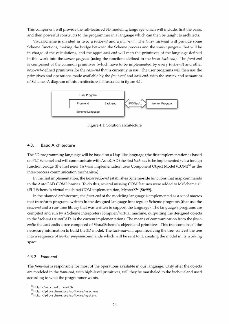
This component will provide the full-featured 3D modeling language which will include, first the basis,and then powerful constructs to the programmer in a language which can then be taught to architects.
VisualScheme is divided in two: a back-end and a front-end. The lower back-end will provide someScheme functions, making the bridge between the Scheme process and the worker program that will bein charge of the calculations, and the upper back-end will map the primitives of the language definedin this work into the worker program (using the functions defined in the lower back-end). The front-endis comprised of the common primitives (which have to be implemented by every back-end) and otherback-end-defined primitives for the back-end that is currently in use. The user programs will then use theprimitives and operations made available by the front-end and back-end, with the syntax and semanticsof Scheme. A diagram of this architecture is illustrated in figure 4.1.
Scheme Language
Back-endFront-end
User Program
IPC/files/... Worker Program
Figure 4.1: Solution architecture
4.3.1 Basic Architecture
The 3D programming language will be based on a Lisp-like language (the first implementation is basedon PLT Scheme) and will communicate with AutoCAD (the first back-end to be implemented) via a foreignfunction bridge (the first lower back-end implementation uses Component Object Model (COM)10 as theinter-process communication mechanism).
In the first implementation, the lower back-end establishes Scheme-side functions that map commandsto the AutoCAD COM libraries. To do this, several missing COM features were added to MzScheme’s11
(PLT Scheme’s virtual machine) COM implementation, MysterX12 [Ste99].In the planned architecture, the front-end of the modeling language is implemented as a set of macros
that transform programs written in the designed language into regular Scheme programs (that use theback-end and a run-time library that was written to support the language). The language’s programs arecompiled and run by a Scheme interpreter/compiler/virtual machine, outputting the designed objectsto the back-end (AutoCAD, in the current implementation). The means of communication from the front-endto the back-endis a tree composed of VisualScheme’s objects and primitives. This tree contains all thenecessary information to build the 3D model. The back-endwill, upon receiving the tree, convert the treeinto a sequence of worker programcommands which will be sent to it, creating the model in its workingspace.
4.3.2 Front-end
The front-end is responsible for most of the operations available in our language. Only after the objectsare modeled in the front-end, with high-level primitives, will they be marshaled to the back-end and usedaccording to what the programmer wants.
10http://microsoft.com/COM11http://plt-scheme.org/software/mzscheme12http://plt-scheme.org/software/mysterx
26
The front-end is available to the programmer as a set of Scheme functions and macros that implementour DSL. Any Scheme program is also a VisualScheme program, which means programmers can uselibraries written for Scheme and divide the program in more manageable parts.
Every model starts in the front-end, by combining several primitives with operations which act onthem. The core language front-end provides several primitives for creating and operating on points andvectors, as well as the core primitive objects. Several transforms and constructive solid geometry (CSG)operations are available for transforming and combining the primitive (or compound) objects.
The full power of the Scheme language is available to the programmer, e.g. for the creation of exten-sions or additional modules. If needed, the core language can also be extended. For most changes theonly thing needed is to add a library to ease the modeling of certain kinds of objects.
One possible extension would be to add more material, shading and reflection options. These optionscan be added to the tree by performing an additional pass after the modeling or by adding them whilemodeling the objects. After the modeling of the object is done in the front-end, the primitive and operationtree is passed to the back-end where it will be marshaled to the final model.
Our Front-end
The front-end is responsible for defining the language that will be available to the programmer and alsothe main structures that will be used by both the front-end and the back-end.
Our front-end defines several basic primitive objects and operations which work on them. As this isa general front-end, the primitives are generally both high-level and simple.
The primitive objects that are available are: circles, solid regions, boxes (parallelepipeds), cones, cylin-ders, spheres, tori, wedges and lofts. A primitive for text drawing is also available.
Transformations on objects, such as translations, rotations an scales are available, as well as operationson sets of objects, such as unions, intersections and differences. These operations accept any createdobject as argument and, just like the primitives, must be implemented in every back-end.
4.3.3 Back-end
The language is made back-end-independent by having a distinction between the language core (whichprovides the primitives and operations that use them) and the back-end (which effectively serializes ordraws the primitives).
The language core is the same regardless of what back-end is in use. A user won’t have to changeanything in his program in order to change the back-end if he only uses the language core. Its functionsand control and data structures are always the same and behave the same in the different back-ends.
The back-end may serialize the models to a file (e.g. a DXF, AutoLISP or POV-Ray SDL file) or use IPCto send commands to a program (e.g. using ActiveX to send commands to AutoCAD) which will thencreate the model’s representations. The back-end is free to optimize the object and operations tree foritself (using more specialized back-end commands) and provide additional primitives for programs thatdon’t need to be portable and require features that are only present in that back-end, as will be seen insection 4.4.
A simple back-end is written by defining a function called draw, which will receive a tree of primitivesand operations and perform the necessary operations to model the tree in that target. A back-end may alsodefine more primitives and operations on these for expanding the language (e.g. primitives for structuralanalysis on top of the 3D models), but must be able to model every core language feature.
27
The AutoCAD Back-end
The AutoCAD back-end was the first implemented back-end. As our immediate goal was to make avail-able a modern language that could replace AutoLISP in an architect’s workflow, we decided to create aLisp-like language that was easy to learn and use for architects and only afterwards would we imple-ment a fully-fledged AutoLISP emulation layer so we could run legacy AutoLISP scripts integrated withscripts in our language. COM communication was chosen as the communication mechanism due to be-ing a well-established IPC mechanism in Microsoft’s Windows operating system and the availability oflibraries to facilitate the communication between our Scheme process and AutoCAD.
It is divided in 3 components: A tiny DSL to facilitate writing code which uses several functions forCOM operations from the MysterX library, bridges for the primitive AutoCAD COM methods whichmodel several primitive objects on AutoCAD’s side and the upper part of the back-end, that acts as acompiler which transforms our trees that are composed of VisuaScheme’s primitives and operations tocommands to be sent to AutoCAD via COM.
COM DSL — The COM DSL is a library which helps developing applications that use COM in the Win-dows version of MzScheme. This DSL, which is implemented on top of MzScheme’s MysterX COMlibrary, has several utility functions and macros to facilitate communication through the COM pro-tocol;
AutoCAD Bridge — The bridge between our language and AutoCAD’s COM automation mechanismsare thin wrappers over the primitive COM methods, which marshal their arguments and invokethem on AutoCAD’s side;
Compiler — The compiler component of the back-end takes a tree of primitives and operations (in ourlanguage’s constructs), optimizes the tree and then interprets it, sending the commands to Auto-CAD and saving the results on the program’s side, if needed.
The compiler’s optimization pass is very basic, but additional passes and transformations may easilybe added. Possible optimizations range from very basic ones (e.g. the scale of a circle (two COM calls)may get transformed to the creation an ellipse (one COM call) and the translation of a box (two COMcalls) may be transformed to the creation of an already translated box (one COM call)) to more complexoptimizations, e.g. the creation ofN objects by instantiating each of theirM components and performingP operations (N × (M + P ) operations) may be transformed to the creation of one prototype object andits subsequent copy and placement on the final position for the other N − 1 objects (M +P +(N − 1)× 2
COM calls13).Adding support for additional features (that may be implemented in a further revision of the core
language or core-dependent primitives) is simple: The new primitive must be added to the compilerdriver so it can be recognized and modeled on the other side. The compiler driver will then call a spe-cialized function to model that object whenever it is encountered. If this is a back-end-specific feature oroperation, its definition must be added (and exported) to the back-end to make it visible to any programwhich uses this back-end.
4.4 Optimizations
In VisualScheme we have mechanisms in place to allow back-end developers to optimize the object andoperation trees and allow the objects to be modeled in a more efficient way.
13M + P operations to create the first object in its desired final location. The other (N − 1) × 2 COM calls copythe object and move the copy to its final location.
28
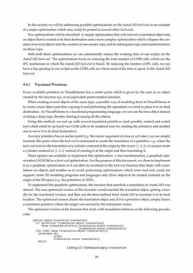
In this section we will be addressing possible optimizations on the AutoCAD back-end as an exampleof a major optimization which may easily be ported to several other back-ends.
Two optimizations will be described: A simple optimization that will convert a translated object intoan object that is created at its final destination and a more complex optimization which collapses the cre-ation of several objects into the creation of one master copy and its subsequent copy and transformationson these copy.
With both these optimizations we can substantially reduce the working time of our scripts on theAutoCAD back-end. The optimizations focus on reducing the total number of COM calls, which are theIPC mechanism in which the AutoCAD back-end is based. By reducing the number of IPC calls, we canhave a big speedup in our scripts as the COM calls are where most of the time is spent, in the AutoCADback-end.
4.4.1 Translated Primitives
Every available primitive in VisualScheme has a center point which is given by the user as an objectcreated by the function xyz, or an equivalent point-creation function.
When creating several objects of the same type, a possible way of modeling them in VisualScheme isto create a base object and then copying it and performing the operations we need to place it in its finaldestination. As VisualScheme is a functional programming language, we can use the base object insteadof doing a deep copy, thereby sharing it among all the objects.
Using this method, we end up with several translated primitives (and possibly rotated and scaledtoo) which entail to (at least) two COM calls to be modeled (one for creating the primitive and anotherone to move it to its final destination).
As every primitive has an anchor point (e.g. the center argument of a box or cylinder), we can simplytranslate this point when the back-end is instructed to create the translation of a primitive: e.g. when theback-end receives the translation of a cylinder centered at the origin by the vector (1, 2, 3), it can just createa cylinder centered at ⟨1, 2, 3⟩ instead of creating it at the origin and then translating it.
Three options are available to implement this optimization: a tree transformation, a peephole opti-mization [ALSU06] or a front-end optimization. For the purpose of this document, we chose to implementit as a peephole optimization as it can then be localized to the back-end function that deals with trans-lations on objects and enables us to avoid performing optimizations which some back-ends could notsupport: some 3D modeling programs and languages only allow objects to be created centered on theorigin of the 3D space (e.g. the primitives in X3D)..
To implement this peephole optimization, the function that marshals a translation to AutoCAD wasaltered. The non-optimized version of this function would marshal the translated object, getting a han-dle for the marshaled version, and then use the Move method from AutoCAD to translate it to its finallocation. The optimized version checks the translation object and, if it is a primitive object, simply drawsa translated primitive where the origin was moved by the translation vector.
The optimized version of the function that deals with translations behaves as the following pseudo-code:
(define (apply-translation translation)(if (primitive? (translation-object translation))
(draw (translate-primitive (translation-object translation)(translation-vector translation)))
(let ([obj (draw (translation-object translation))])(prim:move obj
origin(translation-vector translation))
obj)))
Listing 4.1: Optimized apply-translation
29
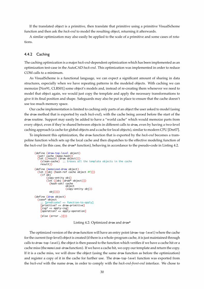
If the translated object is a primitive, then translate that primitive using a primitive VisualSchemefunction and then ask the back-end to model the resulting object, returning it afterwards.
A similar optimization may also easily be applied to the scale of a primitive and some cases of rota-tions.
4.4.2 Caching
The caching optimization is a major back-end-dependent optimization which has been implemented as anoptimization test-case in the AutoCAD back-end. This optimization was implemented in order to reduceCOM calls to a minimum.
As VisualScheme is a functional language, we can expect a significant amount of sharing in datastructures, especially when we have repeating patterns in the modeled objects. With caching we canmemoize [Nor91, CLRS01] some object’s models and, instead of re-creating them whenever we need tomodel that object again, we would just copy the template and apply the necessary transformations togive it its final position and shape. Safeguards may also be put in place to ensure that the cache doesn’tuse too much memory space.
Our cache implementation is limited to caching only parts of an object the user asked to model (usingthe draw method that is exported by each back-end), with the cache being zeroed before the start of thedraw routine. Support may easily be added to have a “world cache” which would memoize parts fromevery object, even if they’re shared between objects in different calls to draw, even by having a two-levelcaching approach (a cache for global objects and a cache for local objects), similar to modern CPU [Dre07].
To implement this optimization, the draw function that is exported by the back-end becomes a tram-poline function which sets up the local cache and then dispatches to the effective modeling function ofthe back-end (in this case, the draw* function), behaving in accordance to the pseudo-code in Listing 4.2.
(define (draw-top-level object)(set! cache (make-hash))(let ([result (draw object)])
(clean-cache) ;; Erases all the template objects in the cacheresult))
(define (memoized-draw object)(let ([obj (hash-ref cache object #f)])
(if obj(copy-entity obj)(let ([obj (draw* object)])
(hash-set! cacheobject(copy-entity obj))
obj))))(define (draw object)
(case* object;; [predicate? => function-to-apply][primitive? => draw-primitive][csg? => apply-csg][operation? => apply-operation][else (error …)]))
Listing 4.2: Optimized draw and draw*
The optimized version of the draw function will have an entry point (draw-top-level) where the cachefor the current (top-level) object is created (if there is a whole-program cache, it is just maintained throughcalls to draw-top-level), the object is then passed to the function which verifies if we have a cache hit or acache miss (the memoized-draw function). If we have a cache hit, we copy our template and return the copy.If it is a cache miss, we will draw the object (using the same draw function as before the optimization)and register a copy of it in the cache for further use. The draw-top-level function was exported fromthe back-end with the name draw, in order to comply with the back-end-front-end interface. We chose to
30
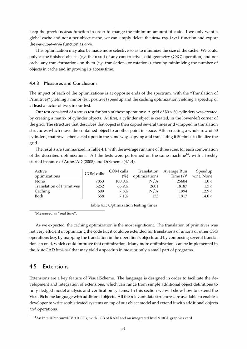
keep the previous draw function in order to change the minimum amount of code. I we only want aglobal cache and not a per-object cache, we can simply delete the draw-top-level function and exportthe memoized-draw function as draw.
This optimization may also be made more selective so as to minimize the size of the cache. We couldonly cache finished objects (e.g. the result of any constructive solid geometry (CSG) operation) and notcache any transformations on them (e.g. translations or rotations), thereby minimizing the number ofobjects in cache and improving its access time.
4.4.3 Measures and Conclusions
The impact of each of the optimizations is at opposite ends of the spectrum, with the “Translation ofPrimitives” yielding a minor (but positive) speedup and the caching optimization yielding a speedup ofat least a factor of two, in our test.
Our test consisted of a stress test for both of these operations: A grid of 50× 50 cylinders was createdby creating a matrix of cylinder objects. At first, a cylinder object is created, in the lower-left corner ofthe grid. The structure that describes that object is then copied several times and wrapped in translationstructures which move the contained object to another point in space. After creating a whole row of 50cylinders, that row is then acted upon in the same way, copying and translating it 50 times to finalize thegrid.
The results are summarized in Table 4.1, with the average run time of three runs, for each combinationof the described optimizations. All the tests were performed on the same machine14, with a freshlystarted instance of AutoCAD (2008) and DrScheme (4.1.4).
Active COM calls COM calls Translation Average Run Speedupoptimizations (%) optimizations Time (s)a w.r.t. NoneNone 7853 100.0% N/A 25604 1.0×Translation of Primitives 5252 66.9% 2601 18187 1.5×Caching 609 7.8% N/A 1994 12.9×Both 558 7.1% 153 1917 14.0×
Table 4.1: Optimization testing timesaMeasured as “real time”.
As we expected, the caching optimization is the most significant. The translation of primitives wasnot very efficient in optimizing the code but it could be extended for translations of unions or other CSGoperations (e.g. by mapping the translation in the operation’s objects and by composing several transla-tions in one), which could improve that optimization. Many more optimizations can be implemented inthe AutoCAD back-end that may yield a speedup in most or only a small part of programs.
4.5 Extensions
Extensions are a key feature of VisualScheme. The language is designed in order to facilitate the de-velopment and integration of extensions, which can range from simple additional object definitions tofully fledged model analysis and verification systems. In this section we will show how to extend theVisualScheme language with additional objects. All the relevant data structures are available to enable adeveloper to write sophisticated systems on top of our object model and extend it with additional objectsand operations.
14An Intel®Pentium®IV 3.0 GHz, with 1GB of RAM and an integrated Intel 910GL graphics card
31
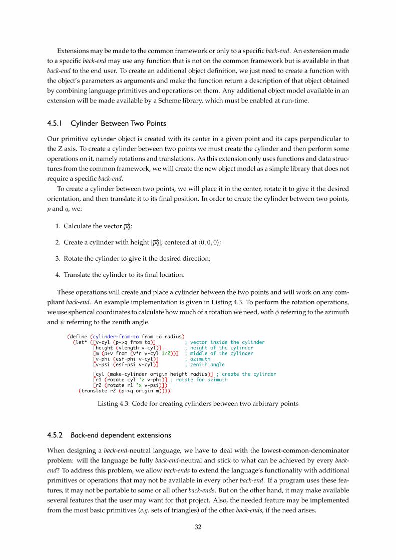
Extensions may be made to the common framework or only to a specific back-end. An extension madeto a specific back-end may use any function that is not on the common framework but is available in thatback-end to the end user. To create an additional object definition, we just need to create a function withthe object’s parameters as arguments and make the function return a description of that object obtainedby combining language primitives and operations on them. Any additional object model available in anextension will be made available by a Scheme library, which must be enabled at run-time.
4.5.1 Cylinder Between Two Points
Our primitive cylinder object is created with its center in a given point and its caps perpendicular tothe Z axis. To create a cylinder between two points we must create the cylinder and then perform someoperations on it, namely rotations and translations. As this extension only uses functions and data struc-tures from the common framework, we will create the new object model as a simple library that does notrequire a specific back-end.
To create a cylinder between two points, we will place it in the center, rotate it to give it the desiredorientation, and then translate it to its final position. In order to create the cylinder between two points,p and q, we:
1. Calculate the vector −→pq;
2. Create a cylinder with height |−→pq|, centered at ⟨0, 0, 0⟩;
3. Rotate the cylinder to give it the desired direction;
4. Translate the cylinder to its final location.
These operations will create and place a cylinder between the two points and will work on any com-pliant back-end. An example implementation is given in Listing 4.3. To perform the rotation operations,we use spherical coordinates to calculate how much of a rotation we need, with ϕ referring to the azimuthand ψ referring to the zenith angle.
(define (cylinder-from-to from to radius)(let* ([v-cyl (p->q from to)] ; vector inside the cylinder
[height (vlength v-cyl)] ; height of the cylinder[m (p+v from (v*r v-cyl 1/2))] ; middle of the cylinder[v-phi (esf-phi v-cyl)] ; azimuth[v-psi (esf-psi v-cyl)] ; zenith angle[cyl (make-cylinder origin height radius)] ; create the cylinder[r1 (rotate cyl ’z v-phi)] ; rotate for azimuth[r2 (rotate r1 ’x v-psi)])
(translate r2 (p->q origin m))))
Listing 4.3: Code for creating cylinders between two arbitrary points
4.5.2 Back-end dependent extensions
When designing a back-end-neutral language, we have to deal with the lowest-common-denominatorproblem: will the language be fully back-end-neutral and stick to what can be achieved by every back-end? To address this problem, we allow back-ends to extend the language’s functionality with additionalprimitives or operations that may not be available in every other back-end. If a program uses these fea-tures, it may not be portable to some or all other back-ends. But on the other hand, it may make availableseveral features that the user may want for that project. Also, the needed feature may be implementedfrom the most basic primitives (e.g. sets of triangles) of the other back-ends, if the need arises.
32
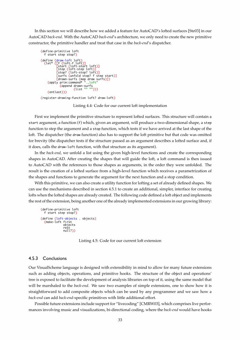
In this section we will describe how we added a feature for AutoCAD’s lofted surfaces [Ste03] in ourAutoCAD back-end. With the AutoCAD back-end’s architecture, we only need to create the new primitiveconstructor, the primitive handler and treat that case in the back-end’s dispatcher.
(define-primitive loftf start step stop?)
(define (draw-loft loft)(let* ([f (loft-f loft)]
[start (loft-start loft)][step (loft-step loft)][stop? (loft-stop? loft)][surfs (unfold stop? f step start)][drawn-surfs (map draw surfs)])
(apply prim:command* ”._loft”(append drawn-surfs
(list ”” ””)))(entlast)))
(register-drawing-function loft? draw-loft)
Listing 4.4: Code for our current loft implementation
First we implement the primitive structure to represent lofted surfaces. This structure will contain astart argument, a function (f) which, given an argument, will produce a two-dimensional shape, a stepfunction to step the argument and a stop function, which tests if we have arrived at the last shape of theloft. The dispatcher (the draw function) also has to support the loft primitive but that code was omittedfor brevity (the dispatcher tests if the structure passed as an argument describes a lofted surface and, ifit does, calls the draw-loft function, with that structure as its argument).
In the back-end, we unfold a list using the given high-level functions and create the correspondingshapes in AutoCAD. After creating the shapes that will guide the loft, a loft command is then issuedto AutoCAD with the references to those shapes as arguments, in the order they were unfolded. Theresult is the creation of a lofted surface from a high-level function which receives a parametrization ofthe shapes and functions to generate the argument for the next function and a stop condition.
With this primitive, we can also create a utility function for lofting a set of already defined shapes. Wecan use the mechanisms described in section 4.5.1 to create an additional, simpler, interface for creatinglofts when the lofted shapes are already created. The following code defined a loft object and implementsthe rest of the extension, being another one of the already implemented extensions in our growing library:
(define-primitive loftf start step stop?)
(define (loft-objects . objects)(make-loft first
objectsrestnull?))
Listing 4.5: Code for our current loft extension
4.5.3 Conclusions
Our VisualScheme language is designed with extensibility in mind to allow for many future extensionssuch as adding objects, operations, and primitive hooks. The structure of the object and operations’tree is exposed to facilitate the development of analysis libraries on top of it, using the same model thatwill be marshaled to the back-end. We saw two examples of simple extensions, one to show how it isstraightforward to add composite objects which can be used by any programmer and we saw how aback-end can add back-end-specific primitives with little additional effort.
Possible future extensions include support for “livecoding” [CMRW03], which comprises live perfor-mances involving music and visualizations, bi-directional coding, where the back-end would have hooks
33

to recreate objects that were inserted in its workspace by means other than the VisualScheme language,or even computing deltas between the iterations of a program and only sending to the worker program thenecessary commands to transform the objects in its workspace to those described in the new iteration ofthe program. Other very important extensions include analyzing the forces involved in the model andwarning the architect if the object is not structurally sound or has a low thermal efficiency, which wouldcut on turnaround time between architects and civil engineers.
34
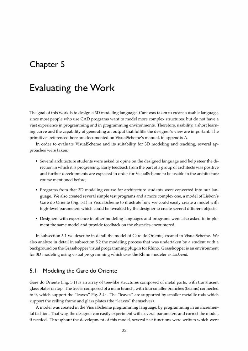
Chapter 5
Evaluating the Work
The goal of this work is to design a 3D modeling language. Care was taken to create a usable language,since most people who use CAD programs want to model more complex structures, but do not have avast experience in programming and in programming environments. Therefore, usability, a short learn-ing curve and the capability of generating an output that fulfills the designer’s view are important. Theprimitives referenced here are documented on VisualScheme’s manual, in appendix A.
In order to evaluate VisualScheme and its suitability for 3D modeling and teaching, several ap-proaches were taken:
• Several architecture students were asked to opine on the designed language and help steer the di-rection in which it is progressing. Early feedback from the part of a group of architects was positiveand further developments are expected in order for VisualScheme to be usable in the architecturecourse mentioned before;
• Programs from that 3D modeling course for architecture students were converted into our lan-guage. We also created several simple test programs and a more complex one, a model of Lisbon’sGare do Oriente (Fig. 5.1) in VisualScheme to illustrate how we could easily create a model withhigh-level parameters which could be tweaked by the designer to create several different objects.
• Designers with experience in other modeling languages and programs were also asked to imple-ment the same model and provide feedback on the obstacles encountered.
In subsection 5.1 we describe in detail the model of Gare do Oriente, created in VisualScheme. Wealso analyze in detail in subsection 5.2 the modeling process that was undertaken by a student with abackground on the Grasshopper visual programming plug-in for Rhino. Grasshopper is an environmentfor 3D modeling using visual programming which uses the Rhino modeler as back-end.
5.1 Modeling the Gare do Oriente
Gare do Oriente (Fig. 5.1) is an array of tree-like structures composed of metal parts, with translucentglass plates on top. The tree is composed of a main branch, with four smaller branches (beams) connectedto it, which support the “leaves” Fig. 5.4a. The “leaves” are supported by smaller metallic rods whichsupport the ceiling frame and glass plates (the “leaves” themselves).
A model was created in the VisualScheme programming language, by programming in an incremen-tal fashion. That way, the designer can easily experiment with several parameters and correct the model,if needed. Throughout the development of this model, several test functions were written which were
35
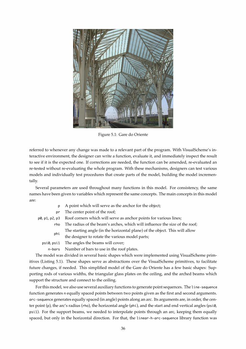
Figure 5.1: Gare do Oriente
referred to whenever any change was made to a relevant part of the program. With VisualScheme’s in-teractive environment, the designer can write a function, evaluate it, and immediately inspect the resultto see if it is the expected one. If corrections are needed, the function can be amended, re-evaluated anre-tested without re-evaluating the whole program. With these mechanisms, designers can test variousmodels and individually test procedures that create parts of the model, building the model incremen-tally.
Several parameters are used throughout many functions in this model. For consistency, the samenames have been given to variables which represent the same concepts. The main concepts in this modelare:
p A point which will serve as the anchor for the object;pr The center point of the roof;
p0, p1, p2, p3 Roof corners which will serve as anchor points for various lines;rho The radius of the beam’s arches, which will influence the size of the roof;
phiThe starting angle (in the horizontal plane) of the object. This will allowthe designer to rotate the various model parts;
psi0, psi1 The angles the beams will cover;n-bars Number of bars to use in the roof plates.
The model was divided in several basic shapes which were implemented using VisualScheme prim-itives (Listing 5.1). These shapes serve as abstractions over the VisualScheme primitives, to facilitatefuture changes, if needed. This simplified model of the Gare do Oriente has a few basic shapes: Sup-porting rods of various widths, the triangular glass plates on the ceiling, and the arched beams whichsupport the structure and connect to the ceiling.
For this model, we also use several auxiliary functions to generate point sequences. The line-sequencefunction generates n equally spaced points between two points given as the first and second arguments.arc-sequence generates equally spaced (in angle) points along an arc. Its arguments are, in order, the cen-ter point (p), the arc’s radius (rho), the horizontal angle (phi), and the start and end vertical angles (psi0,psi1). For the support beams, we needed to interpolate points through an arc, keeping them equallyspaced, but only in the horizontal direction. For that, the linear-h-arc-sequence library function was
36

used, which has, as arguments, the center point (p), the arc’s radius (rho), the horizontal angle (phi), thestart and end vertical angles (psi0, psi1) and the number of points to interpolate (n).
(define (support-rod-medium p0 p1)(make-cylinder p0 p1 0.4))
(define (support-rod-small p0 p1)(make-cylinder p0 p1 0.2))
(define (triangle p0 p1 p2)(do-thicken (make-region (make-line (list p0 p1 p2 p0))) 0.0001))
Listing 5.1: Code for the model’s basic shapes
The model was started by assembling the roof plates (the glass plates and some of the supporting rods,Fig. 5.2). The roof plate is assembled by a function which abstracts some of the details. This functionreceives three points delimiting a triangle (the glass plates are triangles), as well as the number of rodsto embed in the glass (Listing 5.2). The rods function takes two lists of points and creates a rod (a metalcylinder) between each corresponding pair of points in the lists. The triangle function calls the make-3dface primitive, abstracting it to account for possible changes.
(define (roof-plate p0 p1 p2 n)(unite(rods (line-sequence p0 p1 n)
(line-sequence p0 p2 n))(triangle p0 p1 p2)))
Listing 5.2: Function that generates a roof plate
Figure 5.2: Roof plate model
After completing the ceiling plates, the next point of attack was the support beams (Listing 5.3,Fig. 5.3). The support beams’ bases were abstracted by the beam-base function which creates a shapeto be used as the profile of the beam (a 2D surface) and then sweep that shape along a spline to createthe beam itself. The shape of the base is abstracted to enable an easy change of profile. For initial testing,a circle was used as the profile, but later on, the base was changed to be closer to the actual shape. Thebase shape is also scaled along the spline.
After completing the ceiling and the beams, we must unite them using the support rods. These sup-port rods are completely vertical, which forces the designer to model them using an interpolation alongan arc with an equal horizontal spacing between the points (instead of an equal spacing between points).The roof-support (Listing 5.4a) function draws these rods by iterating through sequences of points cal-culated by interpolation. After generating the lists, rods are created from the beam’s arc points to eachof the extremities’ line sequences.
In the last step of the basic prototype (Listing 5.4b), we create a function which will call the previouslymentioned functions, placing the sub-objects in their adequate places, forming the most basic part of
37
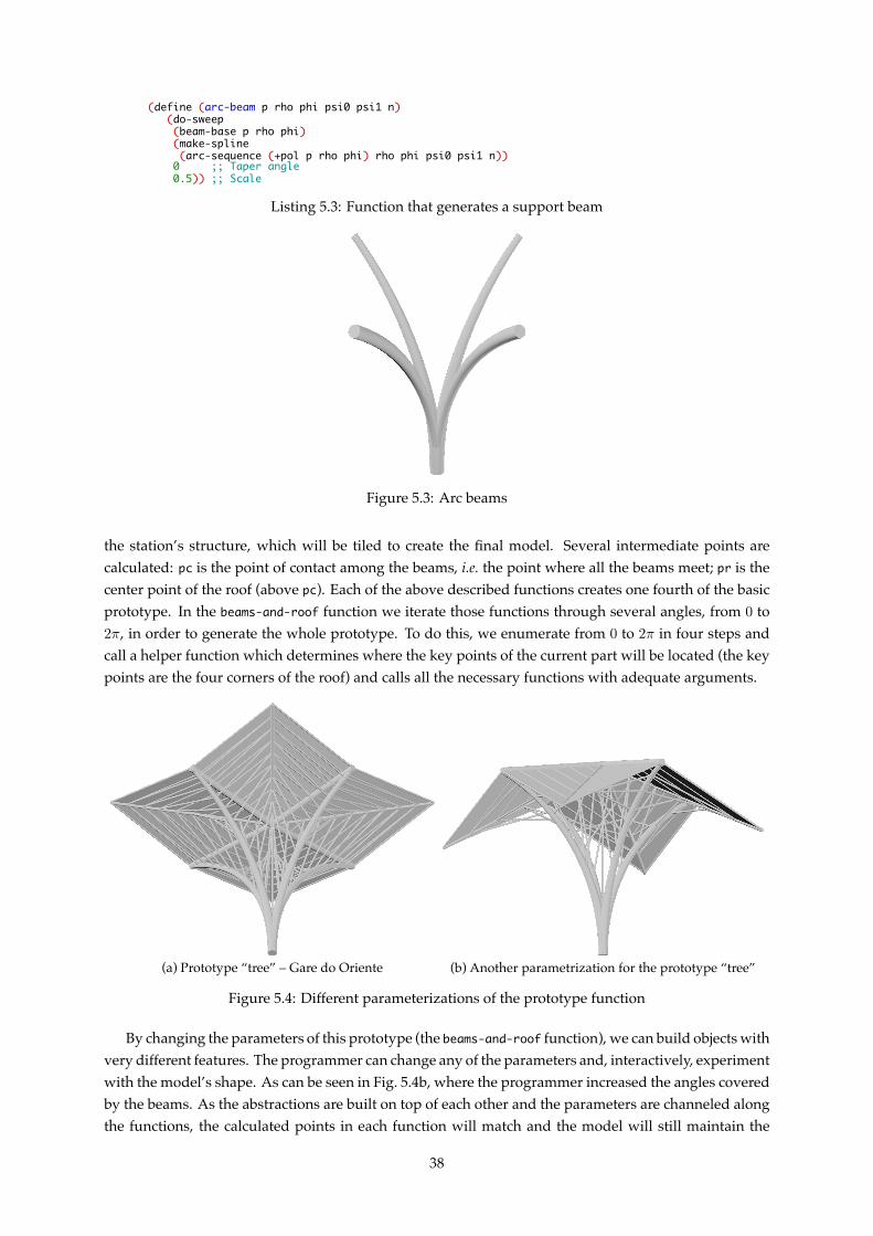
(define (arc-beam p rho phi psi0 psi1 n)(do-sweep(beam-base p rho phi)(make-spline(arc-sequence (+pol p rho phi) rho phi psi0 psi1 n))
0 ;; Taper angle0.5)) ;; Scale
Listing 5.3: Function that generates a support beam
Figure 5.3: Arc beams
the station’s structure, which will be tiled to create the final model. Several intermediate points arecalculated: pc is the point of contact among the beams, i.e. the point where all the beams meet; pr is thecenter point of the roof (above pc). Each of the above described functions creates one fourth of the basicprototype. In the beams-and-roof function we iterate those functions through several angles, from 0 to2π, in order to generate the whole prototype. To do this, we enumerate from 0 to 2π in four steps andcall a helper function which determines where the key points of the current part will be located (the keypoints are the four corners of the roof) and calls all the necessary functions with adequate arguments.
(a) Prototype “tree” – Gare do Oriente (b) Another parametrization for the prototype “tree”
Figure 5.4: Different parameterizations of the prototype function
By changing the parameters of this prototype (the beams-and-roof function), we can build objects withvery different features. The programmer can change any of the parameters and, interactively, experimentwith the model’s shape. As can be seen in Fig. 5.4b, where the programmer increased the angles coveredby the beams. As the abstractions are built on top of each other and the parameters are channeled alongthe functions, the calculated points in each function will match and the model will still maintain the
38

(define (roof-support p pr rho phi psi0 psi1 p0 p1 n-bars)(unite(map (lambda (p0 p1 p2)
(unite(rod p0 p1)(rod p0 p2)))
(reverse (linear-h-arc-sequence p rho (+ phi pi)psi0 psi1 n-bars))
(line-sequence pr p0 n-bars)(line-sequence pr p1 n-bars))))
(a) Roof support rods
(define (beams-and-roof p rho psi0 psi1 n h0 h1 n-bars)(let* ([pc (+z p (arc-height rho pi/2 psi1))] ;; Point of contact among beams
[pr (+z pc (- (arc-height rho psi0 pi/2) h0))] ;; Center of ceiling[r (arc-width rho psi0 pi/2)])
(define helper (phi)(let ([p0 (+cil pr r phi h0)]
[p1 (+cil pr (* (sqrt 2) r) (+ phi pi/4) h1)][p2 (+cil pr r (+ phi pi/2) h0)][p3 (+cil pr (* (sqrt 2) r) (- phi pi/4) h1)])
(unite (support-rod-medium pr p0)(support-rod-small pr p1)(roof-plate pr p0 p1 n-bars)(roof-plate pr p1 p2 n-bars)(arc-beam pc rho phi psi0 psi1 n)(roof-support pc pr rho phi psi0 psi1 p1 p3 n-bars))))
(unite(map helper
(enumerate 0 2*pi 4)))))(b) Completed prototype
Listing 5.4: Prototype “tree” function, which builds one of the basic tree-like structures which will betiled to form the building
desired properties.
Figure 5.5: Gare do Oriente model
Finally, we distribute the prototype along the space we want to occupy with the Gare do Oriente (List-ing 5.5). For this, we use the library function distribute-in-space. This function receives, as argument,a function that creates an object, two points which delimit the space where the first object will be placed,and the number of objects to place in the x, y, and z dimensions. The functional argument will receivea point and create an object around that point. In this example, we calculate the width of an object, sowe can place the objects side by side, controlling overlap among them. The final result can be seen inFig. 5.5.
5.2 Grasshopper Test Case
After completing the Gare do Oriente model, the same test case was given to architecture students, witha background on Grasshopper. The students were supplied with some reference pictures, not the Visu-alScheme model. In this section we will analyze the process of modeling a student undertook. Alongthe development of the Grasshopper model, feedback was gathered from its iterations.
The first attempt was made by creating the whole station as a single object, generating the roof and
39

(define (gare x y)(let ((rho 20)
(psi0 (/ pi 8))(psi1 (/ pi 2)))
(let ((width (* 2 (arc-width rho psi0 psi1))))(distribute-in-space(� (p)
(beams-and-roof p rho psi0 psi1 30 1 3 10))(xyz 0 0 0) ; origin of the box(xyz width width 0) ; box boundaryx ; X dimensiony ; Y dimension1)))) ; Z dimension
Listing 5.5: Function that generates the full Gare do Oriente
the pillars separately. Because of the lack of abstraction in Grasshopper, the student struggled with listsof points which, due to Grasshopper’s programs’ structure, can’t be separated and abstracted, passingthem as arguments to functions. These lists of points had to be generated in different places and, dueto matching failures occurred when generating the object, as can be seen in (Fig. 5.6). These matchingfailures occur more frequently in Grasshopper, due to the lack of named parameters which can commu-nicate information reliably across function calls.
The block structure is rigid and there are many connections which are difficult to track when themodel’s complexity grows. Even when the student tried to abstract parts of the model (by drawinga box around a set of blocks and labeling it (annotation)), the abstraction still forces the user to fullyunderstand how it works (Fig. 5.7).1
The second attempt used the same approach as the VisualScheme version described in section 5.1,i.e. a basic building block was designed and then an array of copies was created. The ceiling plateswere defined as squares and then split in two, to create the bars. While, in the VisualScheme version,the user only needed to change one function in order to change the way these plates were built, in theGrasshopper version, the user has to alter several connections and blocks, possibly losing track of someof them.
The student also struggled with the precise control of the object’s features (e.g. height), due to nothaving blocks available in Grasshopper for those purposes. The alternative would be to deviate fromGrasshopper’s proposed paradigm and use a block explicitly programmed in VB.NET or C# to createthe arbitrary blocks needed, with appropriate inputs and outputs.
Eventually, even though steps were taken to avoid it, the complexity forced the user to create someVB.NET blocks with custom functions for sweep-related problems which were encountered during themodeling. The final model also had some parameters which could be controlled by editing VB.NETblocks, which would behave as feature selectors. This approach was chosen because, in a complex model,altering the way the model is built may involve changing many connections which, in a complex model,easily becomes unwieldy. What, in VisualScheme, can be accomplished by passing a function as a pa-rameter, cannot be done in Grasshopper and the user must fall-back to a less flexible approach if thisparametrization is desired.
If, during model building, the designer wants to add details to the model, the Grasshopper programmust always be redesigned (except for very basic changes, such as changing the number of divisions ofa line segment or controlling the size of basic shapes) and more connections must be added. Also with awell-abstracted model (abstracted using lines), many connections must be changed, even for a minimalchange, as the abstractions do not eliminate (nor mask) these connections. Some connections may behidden from the user (e.g. to aggregate all the model’s parameters in the same place), but these hiddenconnections may, in fact, difficult the reading of the program when, later, a designer wants to understand
1The user can’t simply use these “abstractions”, e.g. if we abstract a beam using an annotation, the user will stillhave to know that a beam is an extrude along a path, find that set of blocks, and feed it with the desired parameters.
40
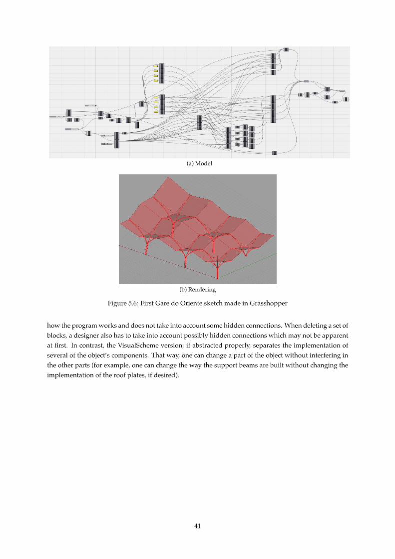
(a) Model
(b) Rendering
Figure 5.6: First Gare do Oriente sketch made in Grasshopper
how the program works and does not take into account some hidden connections. When deleting a set ofblocks, a designer also has to take into account possibly hidden connections which may not be apparentat first. In contrast, the VisualScheme version, if abstracted properly, separates the implementation ofseveral of the object’s components. That way, one can change a part of the object without interfering inthe other parts (for example, one can change the way the support beams are built without changing theimplementation of the roof plates, if desired).
41
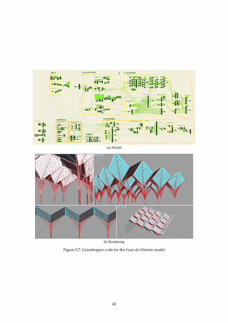
(a) Model
(b) Rendering
Figure 5.7: Grasshopper code for the Gare do Oriente model
42

Chapter 6
Conclusions
Most complex buildings are practically impossible to design manually, even with CAD tools.1 Somemeans must be available in CAD programs to allow designers to express themselves without that lim-itation. One way to remove that limitation is to provide designers with a programming language withwhich they can programatically define and combine objects to form complex figures. With a program-ming language, designers have full control to define mathematical expressions which establish size andproportion relations among object’s components and easily model objects according to those functions.
Being a project with a goal that depends not only on users’ (architects) tastes, but also on the expres-sive power and ease of use of the language by experienced programmers, the balance of features andcomplexity of the language must be balanced with extreme care. The language should be easy to learnto someone experienced with CAD tools. AutoCAD is an unavoidable player in the CAD business sothe language should, at the very least, be marginally familiar to someone who already uses AutoCAD’sautomation features.
With this work we’ve produced a high-level, teaching oriented (which is also adequate for a produc-tion environment) language for 3D modeling, called VisualScheme. The language is a DSL built on top ofthe Lisp-like language Scheme, inheriting its simple syntax and semantics. Besides retaining Scheme’scharacteristics, VisualScheme adds the CAD functionality on top of it, by defining the basic primitiveobjects and operations. This language has a common front-end and multiple back-ends available for themodel output. From one programmatic definition of a 3D model we can create several ones for use ina 3D modeling program, ranging from CAD systems to simple visualizers or generating the OpenGLcode to use the model in a video game. This language is extensible and the end-user (or a library devel-oper) can extend it as needed, adding primitives for new objects, operations or other features, such asthe ability to test building evacuations or optimizations on the programmed model. A back-end imple-menter may also define back-end-specific extensions or optimizations which will only be available in thatback-end.
With VisualScheme’s interactive environment, the designer can build models incrementally and testeach part individually. Testing, amending and re-evaluating various models becomes a simpler task withimmediate results, which allows the designer to experiment with different parameters until the modelacquires its final form.
With this language, we open the doors to a generative architecture. Although not a complete nov-elty, this field of architecture was previously closed to people who did not know low-level languageslike C/C++, Java or Visual Basic. With VisualScheme, we open this field to many architects who are al-ready familiar with AutoLISP, and we provide a simple, high-level, easy to learn language to architects,
1Some kinds of buildings, that employ complex mathematical functions in their design can even be impossibleto design manually.
43

whom we can teach how to use these tools to their advantage for rapid prototyping and the creation ofparametrizable objects which can be used to explore a whole range of possibilities for a given architectureproject, facilitating and fostering experimentation and exploration.
44
6.1 Future Work
Several projects may derive from this work, enhancing VisualScheme’s potential as a multi-purpose lan-guage for 3D object modeling. These enhancements would make VisualScheme suitable for many morefields where modeling 3-dimensional objects is a requirement or a desired feature. From those possibleenhancements, we highlight the following:
• Adding more primitives for 3D object modeling, including utility functions for other coordinatesystems, support for textures or more parametrized objects and high-level operators. The creationof generic versions of some back-end-dependent features (such as AutoCAD’s loft) will also betaken into account to increase the portability of 3D models;
• Incorporating VisualScheme in programming courses targeted at architecture students and teach-ing them how to model parametrizable 3D objects programmatically;
• Implementing more VisualScheme back-ends, such as a POV-Ray, Maya2, Renderman3;
• Translators may be created to convert POV-Ray worlds (or other 3D models from other software)into VisualScheme for use in other modeling programs for which a VisualScheme back-end is im-plemented. An AutoLISP emulation layer may also be implemented on top of VisualScheme, inorder to ease the transition for AutoLISP users who already have sizable AutoLISP libraries andprograms;
• Extending DrScheme or creating a new IDE for VisualScheme, to aid students and professionals intheir 3D modeling by offering visual cues and low detail previews of the objects currently beingmodeled in the IDE, on-the-fly;
• Implementing the ability to round-trip between a VisualScheme program and the back-end, in orderto ease the translation of any changes made to the project outside VisualScheme to the originalsource program (for example, when sharing the project with a civil engineer which can annotateour project);
• Using the ability to model 3D objects and using the same model to test for structural integrity,evacuation strategies in case of fire or other hazards, among other applications;
2http://autodesk.com/maya3https://renderman.pixar.com/
45

46
Appendix A
VisualScheme Manual
In this chapter, we define the VisualScheme language’s primitive objects and operations. VisualScheme’ssyntax is the same as PLT Scheme’s [FFS08], except where otherwise noted. Manual entries are presentedas follows:
Object
(obj argument-1)(obj [argument-1 positive?] argument-2 . [rest (list-of number?)])
Also seen in: AutoCAD, GML
This entry describes the constructors of an hypothetical object. This object may be constructed usinga procedure of one or two or more arguments. The first version (which has exactly one argument) canbe called with arguments of any type. The second version may be called with two or more arguments.The first argument must be a positive number, the second argument has no type restrictions, while thearguments after it, if provided, must be numbers. This is accomplished using typing predicates.
A typing predicate is a procedure which must return true (#t) when called with an object of that typeas argument. Any VisualScheme procedure may be used as a typing predicate. Typing predicates mayalso be created using the built-in helpers: list-of, and and or. The list-of helper provides a way to applya typing predicate to every member of a list. The and and or helpers allow the typing of conjunctionsand disjunctions of properties (for example, a natural number will obey a predicate of (and integer?positive?)). The object? typing predicate identifies one of VisualScheme’s 3D objects by returning #t ifits argument is the result of a VisualScheme primitive or operation. Data types are available for points(point), vectors (gvector), axis (axis) and planes (plane).
In the following sections a description of VisualScheme’s available primitives and operations arepresented, along with their constructor’s arguments. A reference is also made to some other languagesor CAD products where a similar primitive/operation can be found.
A.1 Primitives
A.1.1 2D Primitives
3DFace
(make-3dface [p1 point-3d?] [p2 point-3d?] [p3 point-3d?] [p4 point-3d?])Also seen in: AutoCAD and stuff
47
Creates a solid-filled area (2D) between the specified four points. The points must be non-collinear.
Arc
(make-arc [c point?] [r positive?] [angle real?])(make-arc [c point?] [r positive?] [start-angle real?] [end-angle real?])
Also seen in: AutoCAD, GML, and others
Creates an arc perpendicular to the Z axis, with the center at c, radius of radius units, from zero toangle radians. The four argument version is equivalent, but starts at start-angle radians and creates anarc with (end-angle − start-angle) radians.
Circle
(make-circle [c point?] [r point?])Also seen in: AutoCAD, POV-Ray, GML
Creates a circle with center in c and a radius of r units. Similar to the ellipse with r1 = r2.
Donut
(make-donut [c point?] [r1 positive?] [r2 positive?])Also seen in: AutoCAD, PLaSM
Creates a circle of radius r1 with a hole in the middle, of radius r2. Both the circle and the hole arecentered at point c.
Ellipse
(make-ellipse [c point?] [r1 positive?] [r2 positive?])Also seen in: AutoCAD, GML, and others
Creates an ellipse with center at c, and radii r1 and r2.The radius defined by r1 will be parallel to theX axis, while the one defined by r2 will be parallel to the Y axis.
Filled region
(make-region [l primitive?])Also seen in: AutoCAD, at least
Creates a solid-filled region with l as its delimiter line, which has to be closed.
Infinite line
(make-xline [p1 point?] [p2 point?])Also seen in: AutoCAD, at least
Creates an infinite line which passes through both p1 and p2.
48
Line
(make-line [p1 point?] [p2 point?])(make-line [pts (list-of point?)])
Also seen in: AutoCAD, X3D, GML, and others
Creates a line between p1 and p2. The second version creates a line which passes by all the pointsgiven as arguments, in order.
Parametric surface
(make-surface [f procedure?] [u-min real?] [u-max real?] [v-min real?] [v-max real?])(make-surface [f procedure?])(make-surface [fx procedure?] [fy procedure?] [fz procedure?])(make-surface [fx procedure?] [fy procedure?] [fz procedure?]
[u-min real?] [u-max real?] [v-min real?] [v-max real?])Also seen in: AutoCAD (surface from a set of points), PLaSM
Creates a parametric surface using the procedure passed as argument as generator. Two possibilitiesexist for the procedures: Either a single procedure (f) will yield a 3-dimensional point, given the u andv coordinates in the surface, or 3 procedures (fx, fy and fz) will yield each of the point’s coordinates(x, y and z, respectively). The points that result from applying the procedure(s) to every point withcoordinates between (u-min, v-min) and (u-max, v-max) will be part of the surface.
Ray
(make-ray [p point?] [dir gvector?])Also seen in: AutoCAD, POV-Ray
Creates a ray, which is a line finite in one direction and infinite in the other. The ray will start at p1and follow the direction of the dir vector.
Spline
(make-spline [pts (list-of point?)] [start-tg number?] [end-tg number?])(make-spline [pts (list-of point?)])(make-spline [pt1 point?] [pt2 point?] . [pts (list-of point?)])
Also seen in: AutoCAD, GML, and others
Creates a spline passing through all the points in pts (and pt1, pt2, if applicable), with parameteriz-able start and end tangents (using start-tg and end-tg).
Text
(make-text [origin point?] [size (and integer? positive?)] [str string?])Also seen in: AutoCAD, GML, POV-Ray
Creates a text, with origin as its lower-left point, of size size, with string as its content.
49
A.1.2 3D Primitives
Box
(make-box [p1 point?] [p2 point?])(make-box [c point-3d?] [w positive?] [l positive?] [h positive?])
Also seen in: AutoCAD, GML, X3D
The first version creates a box between p1 and p2, while the second version creates a box with centerat c, with width w, length l and height h.
Cone
(make-cone [c1 point?] [c2 point?] [r positive?])Also seen in: AutoCAD, POV-Ray, X3D
Creates a cone with its base at c1, with radius r and endpoint at c2.
Cut cone
(make-cut-cone [c1 point?] [r1 positive?] [c2 point?] [r2 positive?])Also seen in: AutoCAD, POV-Ray, PLaSM
Creates a cone with its top truncated. The bottom base will be centered at c1 with a radius of r1, whilethe top base will be centered at c2 with r2 as its radius.
Cylinder
(make-cylinder [c1 point-3d?] [h positive?] [r positive?])(make-cylinder [c1 point-3d?] [c2 point-3d?] [r positive?])
Also seen in: AutoCAD, POV-Ray, X3D
Creates a cylinder with a base in c1, a radius r and a height h (parallel to the Z axis). The alternativeversion creates a cylinder with its bases at c1 and c2, with a radius r.
Elliptical cone
(make-e-cone [c1 point-3d?] [r1 positive?] [r1* positive?] [c2 point-3d?] [r2 positive?])Also seen in: AutoCAD, PLaSM, GML
Creates an elliptical cone (a cone with an ellipse as its base). The lower base will be centered at c1while the upper base will be centered at c2. The major and minor radii of the lower base are given by r1and r1*, while the major radius of the upper base is given by r2 (both bases share the same ratio betweenradii).
Mesh
(make-mesh [pts-array (list-of (list-of point-3d?))])Also seen in: AutoCAD (3DMESH), POV-Ray, GML
Creates a mesh object with the points specified in the array. The array must be rectangular (withM ×N points).
50
Polyface Mesh
(make-polyface-mesh [verts point-3d?] [faces (list-of (list-of (and positive? integer?)))])Also seen in: AutoCAD (PFACE), POV-Ray, PLaSM
Creates a 3-dimensional mesh object with the faces defined in the faces array. the faces array willcontain sets of numbers which index the verts list, creating faces with the referenced vertices.
Pyramid
(make-pyramid [c1 point?] [r positive?] [s (and integer? positive?)] [c2 point?])(make-pyramid [c1 point?] [r positive?] [s (and integer? positive?)] [c2 point?]
[r2 positive?])Also seen in: AutoCAD, GML
Creates a pyramid of s sides, between c1 and c2. Its lower base (centered at c1) will have radius r. Itsupper base will either be an endpoint (first version) or have r2 radius.
Sphere
(make-sphere [c point-3d?] [r positive?])Also seen in: AutoCAD, GML, PLaSM
Creates a sphere with center c and radius r.
Superellipsoid
(make-supperellipsoid [e positive?] [n positive?] [s positive?])Also seen in: POV-Ray
Creates a superquadric ellipsoid, which can be used to create boxes and cylinders with round edges,among other interesting shapes. The superquadric ellipsoid is described by the following equation, oc-cupying roughly the same space as the result of (make-box (xyz (- s) (- s) (- s)) (xyz s s s)):
f(x, y, z) =(|x|(
2e ) + |y|(
2e ))( e
n )+ |z|(
2n ) = s
Torus
(make-torus [c point-3d?] [r positive?] [t-r positive?])Also seen in: AutoCAD, GML, X3D
Creates a torus centered in c, with a radius r and a tube radius of t-r.
Wedge
(make-wedge [p1 point?] [p2 point?])(make-wedge [c point-3d?] [l positive?] [w positive?] [h positive?])
Also seen in: AutoCAD, GML
Creates a wedge between p1 and p2. The second version creates a wedge with a center in c, width w,height h and length l.
51
A.1.3 Operations
Edges
(do-edges [object object?])Also seen in: AutoCAD, PLaSM
Yields the wireframe of a 3D object.
Extrusion
(do-extrude [surf object?] [p (or positive? vector-3d? primitive?)])(do-extrude [surf object?] [p (or positive? vector-3d? primitive?)] [taper real?])
Also seen in: GML, POV-Ray
Extrudes a surface surf along a line p, tapering taper-angle radians. If p is a number, extrudes p unitsin the Z direction. If it is a vector or a line (straight or curved), extrusion is performed in its direction.
Guided loft
(do-guided-loft [objects (list-of object?)] [guides (list-of primitive?)])(do-guided-loft [objects (list-of object?)] [path primitive?])
Also seen in: AutoCAD, PLaSM
Lofts the objects passed in objects either using guides of a path. If using guides, the objects willbe lofted using the objects in the second argument as guide curves, tracing the path of matching pointsalong the guides. If a path is used, the objects are traced along that path.
Intersection
(intersect [args (list-of object?)])Also seen in: AutoCAD, POV-Ray, GML
Yields the intersection of all the objects passed as arguments.
Loft
(do-loft [objects (list-of object?)])(do-loft [objects (list-of object?)] [a1 real?] [m1 positive?] [a2 real?] [m2 positive?])
Also seen in: AutoCAD, PLaSM
Lofts the shapes in the list passed as the objects argument. The version with one argument behavesas if 0 was passed as every argument except the first. The a1, m1, a2 and m2 control, respectively, the draftangle and magnitude of the first and last cross sections of the lofted object.
Mirror
(do-mirror [object object?] [plane plane?])Also seen in: AutoCAD, PLaSM
Mirrors an object with relation to a given plane.
52
Move
(do-move [object object?] [vector gvector?])Also seen in: AutoCAD, POV-Ray, GML, PLaSM
Displaces an object in the direction of vector.
Offset
(do-offset [line object?] [distance real?])Also seen in: AutoCAD, PLaSM
Offsets a line (straight or curved), for a specified distance. Offset lines are always parallel (or con-centric, if offsetting an arc or circle) to the original object.
Revolution
(do-revolve [surface object?] [axis axis?])(do-revolve [surface object?] [axis axis?] [start-angle real?] [end-angle real?])
Revolves a surface along an axis, between start-angle and end-angle. If the latter arguments are notsupplied, they are assumed as 0 and 2π radians, respectively.
Rotation
(do-rotate [object object?] [axis axis?] [angle real?])(do-rotate [object object?] [point point?] [vector gvector?] [angle real?])
Also seen in: AutoCAD, POV-Ray, GML
Rotates the specified object along the given axis, using the axis’ point of reference as the origin, forthe specified angle. The axis may be given as an axis object or as a separate point and geometrical vector.
Ruled loft
(do-ruled-loft [objects (list-of object?)])Also seen in: AutoCAD, PLaSM
Creates a ruled loft with the specified objects. The loft will be straight, with sharp edges at the cross-sections.
Scale
(do-scale [object object?] [point point?] [factor positive?])Also seen in: AutoCAD, GML
Scales an object to factor times its original size, using point as reference.
Slice
(do-slice [object object?] [plane plane?])Also seen in: AutoCAD, POV-Ray
53
Slices the object along the specified plane, keeping the portion which is in the plane’s normal direc-tion.
Subtraction
(subtract [object object?])(subtract [object object?] . [args (list-of object?)])
Also seen in: AutoCAD, PLaSM, GML
Subtracts from the first argument the union of all the other arguments, yielding the resulting object.In the version with only one argument, the result is a procedure which will receive as arguments theobjects to subtract.
Sweep
(do-sweep [surface primitive?] [path primitive?])(do-sweep [surface primitive?] [path primitive?] [twist real?] [scale positive?])
Also seen in: AutoCAD, GML, PLaSM
Similar to an extrusion but aligns the surface with the path. A sweep can also be parameterized witha twist angle (the amount of twist the surface will suffer along the path) and a scale factor. The twistand scale parameters have a default of 0 and 1, respectively.
Thicken
(do-thicken [line object?] [width positive?])Also seen in: AutoCAD, GML
Creates a 3D solid from a 2D surface or line, by thickening it.
Transform
(do-transform [object object?] [matrix matrix?])Also seen in: AutoCAD, POV-Ray, GML
Transforms an object according to a 4x4 transformation matrix.
Union
(unite [args (list-of object?)])Also seen in: AutoCAD, PLaSM, GML
Yields an object representing the union of all the objects passed as arguments.
54
Bibliography
[ALSU06] Alfred V. Aho, Monica S. Lam, Ravi Sethi, and Jeffrey D. Ullman. Compilers: Principles,Techniques, and Tools (2nd Edition). Addison Wesley, August 2006.
[AP07] Rémi Arnaud and Tony Parisi. Developing web applications with collada and x3d.COLLADA, 2007. See http://www.khronos.org/collada/presentations/Developing_Web_Applications_with_COLLADA_and_X3D.pdf.
[AS04] ARB and Dave Shreiner. The OpenGL Reference Manual. The Open Group, 4 edition, 2004.[ASS96] Harold Abelson, Gerald Jay Sussman, and Julie Sussman. Structure and Interpretation of Com-
puter Programs. MIT Press, second edition, 1996.[Aut08] Autodesk. AutoCAD 2009 DXF Reference. Autodesk, San Rafael, CA, USA, January 2008. See
http://images.autodesk.com/adsk/files/acad_dxf.pdf.[Aut09] Autodesk. AutoLISP Developer’s Guide. Autodesk, San Rafael, CA, USA, 2009.[AWW91] Alexander Aiken, John H. Williams, and Edward L. Wimmers. The FL project: The design
of a functional language, 1991.[Bac78] John Backus. Can Programming Be Liberated from the von Neumann Style? A Functional
Style and Its Algebra of Programs. Communications of the ACM, 21(8), August 1978.[BEJZ09] Johannes Behr, Peter Eschler, Yvonne Jung, and Michael Zöllner. X3DOM: a dom-based
html5/x3d integration model. In Web3D ’09: Proceedings of the 14th International Conferenceon 3D Web Technology, pages 127–135, New York, NY, USA, 2009. ACM.
[BFPP93] F. Bernardini, V. Ferrucci, A. Paoluzzi, and V. Pascucci. Product Operator on Cell Complexes.In SMA ’93: Proceedings on the Second ACM Symposium on Solid Modeling and Applications.ACM, 1993.
[Bly06] David Blythe. The Direct3D 10 system. ACM Trans. Graph., 25(3):724–734, 2006.[Cli91] William Clinger. Hygienic macros through explicit renaming. SIGPLAN Lisp Pointers,
IV(4):25–28, 1991.[CLRS01] Thomas H. Cormen, Charles E. Leiserson, Ronald L. Rivest, and Clifford Stein. Introduction
to Algorithms. The MIT Press, 2nd edition, 2001.[CMRW03] Nick Collins, Alex Mclean, Julian Rohrhuber, and Adrian Ward. Live coding in laptop per-
formance. Organised Sound, 8(03):321–330, 2003.[Dre07] Ulrich Drepper. What every programmer should know about memory. Technical report,
Red Hat, Inc., 2007.[DS07] Andreas Dietrich and Philipp Slusallek. Massive model visualization using realtime ray
tracing. In SIGGRAPH ’07: ACM SIGGRAPH 2007 courses, page 10. ACM, 2007.[FCF+02] Robert Bruce Findler, John Clements, Cormac Flanagan, Matthew Flatt, Shriram Krishna-
murthi, Paul Steckler, and Matthias Felleisen. Drscheme: A programming environment forscheme. In in PLILP 1997, LNCS, pages 369–388, 2002.
[FFFK03] Matthias Felleisen, Robert Bruce Findler, Matthew Flatt, and Shriram Krishnamurthi. TheTeachScheme! project: Computing and programming for every student, 2003.
55
[FFS08] Matthew Flatt, Robert Bruce Findler, and PLT Scheme. Guide: PLT Scheme. IntroductionPLT-TR2008-guide-v4.1.3, PLT Scheme Inc., November 2008. See http://plt-scheme.org/techreports/.
[Hav03] Sven Havemann. An Introduction to the Generative Modeling Language: GML Tu-torial. http://generative-modeling.org/GenerativeModeling/Documents/gml_tutorial.pdf,June 2003.
[Hav05] Sven Havemann. Generative Mesh Modelling. PhD thesis, Technische Universität Braun-schweig, 2005.
[HDG09] G.C. Henriques, J.P. Duarte, and M. C. Guedes. Sustainable housing cells: Mass customiza-tion of sustainable collective housing. In Proceedings of the 2009 International conference onsustainable development in building and environment, Chongqing, China, 2009.
[ISO96] ISO 14772-1:1996. The Virtual Reality Modeling Language Specification, Version 2.0,. ISO,Geneva, Switzerland, 1996.
[ISO04] ISO 19775:2004. Information technology – Computer graphics and image processing – Extensible3D (X3D). ISO, Geneva, Switzerland, 2004.
[ISO05] ISO 19776:2005. Information technology – Computer graphics and image processing – Extensible3D (X3D) encodings. ISO, Geneva, Switzerland, 2005.
[ISO06] ISO 19777:2006. Information technology - Computer graphics and image processing - Extensible 3D(X3D) language bindings. ISO, Geneva, Switzerland, 2006.
[ISO08a] ISO 19775-1:2008. Information technology - Computer graphics and image processing - Extensible3D (X3D). ISO, Geneva, Switzerland, 2008.
[ISO08b] ISO 32000-1:2008. Document management – Portable document format – Part 1: PDF 1.7. ISO,Geneva, Switzerland, 2008.
[ISO08c] ISO 9075:2008. Information technology —- Database languages —- SQL. ISO, Geneva, Switzer-land, 2008.
[KCR98] Richard Kelsey, William Clinger, and Jonathan Rees. Revised5 Report on the AlgorithmicLanguage Scheme. Higher-Order and Symbolic Computation, 11(1):7–105, 1998.
[Lat02] Chris Lattner. LLVM: An Infrastructure for Multi-Stage Optimization. Master’s thesis,Computer Science Dept., University of Illinois at Urbana-Champaign, December 2002. Seehttp://llvm.cs.uiuc.edu.
[Ley01] Michael Leyton. A Generative Theory of Shape, volume 2145 of Lecture Notes in Computer Sci-ence. Springer Berlin/Heidelberg, November 2001.
[LMFC10] António Menezes Leitão, Bruno Matos, Paulo Fontainha, and Filipe Cabecinhas. Revisitingthe architecture curriculum. In Proceedings of the 2010 Education and research in Computer AidedArchitectural Design in Europe, 2010. Forthcoming.
[MHS05] Marjan Mernik, Jan Heering, and Anthony M. Sloane. When and how to develop domain-specific languages. ACM Comput. Surv., 37(4):316–344, 2005.
[Mol99] Karen. Moltenbrey. A tale of two cities: How cad simultaneously transformed an old, run-down section of lisbon into a world’s fair site and a new, ultra-modern ’city within a city’.Computer Graphics World, 22(6), 1999.
[Mos70] Joel Moses. The function of FUNCTION in LISP or why the FUNARG problem should becalled the environment problem. SIGSAM Bulletin, pages 13–27, 1970.
[Muu95] M J Muuss. Towards real-time ray-tracing of combinatorial solid geometric models. In inProceedings of BRL-CAD Symposium, 1995.
[Nor91] Peter Norvig. Techniques for automatic memoization with applications to context-free pars-ing. Comput. Linguist., 17(1):91–98, 1991.
56

[Per01] Persistence of Vision Raytracer Pty. Ltd. POV-Ray Documentation: The early history of POV-Ray, 2001.
[PI09] Andrew Payne and Rajaa Issa. The Grasshopper Primer. LIFT Architects, 2009.[PMS+05] Steven Parker, William Martin, Peter-Pike J. Sloan, Peter Shirley, Brian Smits, and Charles
Hansen. Interactive ray tracing. In SIGGRAPH ’05: ACM SIGGRAPH 2005 Courses, page 12,New York, NY, USA, 2005. ACM.
[PPV95] Alberto Paoluzzi, Valerio Pascucci, and Michele Vicentino. Geometric Programming: AProgramming Approach to Geometric Design. ACM Transactions on Graphics, 14(3), 1995.
[PS92] A. Paoluzzi and C. Sansoni. Programming Language for Solid Variational Geometry.Computer-Aided Design, 24(7), 1992.
[PVBP01] Alberto Paoluzzi, M. Vicentino, C. Baldazzi, and Valerio Pascucci. Geometric Programmingfor Computer Aided Design. John Wiley & Sons, Inc., 2001.
[Sco00] Michael L. Scott. Programming Language Pragmatics. Morgan Kaufmann Publishers Inc., SanFrancisco, CA, USA, second edition, 2000.
[SDF+07] Michael Sperber, R. Kent Dybvig, Matthew Flatt, Anton van Straaten, Richard Kelsey,William Clinger, Jonathan Rees, Robert Bruce Findler, and Jacob Matthews. Revised6 Reporton the Algorithmic Language Scheme. See http://www.r6rs.org/., 2007.
[SG96] Guy L. Steele and Richard P. Gabriel. The evolution of Lisp. In The second ACM SIGPLANconference on History of programming languages, pages 233–330, New York, NY, USA, 1996.ACM.
[Shi98] Clay Shirky. And nothing to watch: playfulness in 3-d spaces. netWorker, 2(4):56, 1998.[Ste99] Paul A. Steckler. MysterX: A Scheme toolkit for building interactive applications with COM.
In In Technology of Object-Oriented Languages and Systems (TOOL), pages 364–373. IEEE, 1999.[Ste03] David M. Stein. The Visual LISP Developers Bible — Visual LISP Development with AutoCAD
2004. David M. Stein, second edition, 2003.[Web05] Web3D. Web3D X3D Frequently Asked Questions. Web3D, March 2005. See http://web3d.org/
about/faq.
[WG07] Noel Welsh and David Gurnell. Experience report: scheme in commercial web applicationdevelopment. SIGPLAN Not., 42(9):153–156, 2007.
57