a guide to how the freebsd kernel manages the ia32 ... · various memory structures used by the...
TRANSCRIPT
A guide to how the FreeBSD kernel manages the IA32 processors in Protected Mode
(c) 2004, Arne Vidstrom, http://vidstrom.net
Version 1.0 : 2004-06-17
Table of contents
1. PREREQUISITE KNOWLEDGE....................................................................................2 2. INFORMATION SOURCES ..........................................................................................2 3. THE INTERRUPT DESCRIPTOR TABLE (IDT) ............................................................2
3.1 The IDT definition............................................................................................2 3.2 Setting entries in the IDT .................................................................................3 3.3 A look inside the IDT with KernView ..............................................................4 3.4 Making the IDT active .....................................................................................5
4. SYSCALL HANDLING ...............................................................................................6 4.1 The INT 0x80 interrupt handler.......................................................................6 4.2 Syscall dispatching...........................................................................................8 4.3 The copyin() function .....................................................................................10
5. THE GLOBAL DESCRIPTOR TABLE (GDT).............................................................12 5.1 The GDT definition ........................................................................................12 5.2 Setting up the descriptors in the GDT............................................................13 5.3 Making the GDT active..................................................................................16 5.4 A look inside the GDT with KernView...........................................................17 5.5 Segment selector values in an ordinary user mode program ........................21
6. TASK SWITCHING ..................................................................................................22 6.1 The cpu_switch() function..............................................................................22
7. VIRTUAL PAGING ..................................................................................................29 7.1 The page fault handler ...................................................................................29 7.2 Virtual paging and task switching .................................................................32
8 THE LOCAL DESCRIPTOR TABLE (LDT).................................................................32 8.1 A quick glance at the LDT .............................................................................32
9. MISCELLANEOUS ..................................................................................................34 9.1 The uiomove() function ..................................................................................34
1. Prerequisite knowledge This guide assumes that the reader is familiar with how the IA32 processors work in Protected Mode, with the C programming language, and with AT&T syntax IA32 assembler programming. It also assumes some knowledge about user mode system programming for FreeBSD and some general knowledge about the internal workings of the kernel.
2. Information sources The primary source of information used when writing this guide has been the FreeBSD kernel source code itself. The FreeBSD Kernel Cross-Reference at http://fxr.watson.org/ has been very valuable for doing easy searches in the kernel source code, but the source code snippets in the text comes from the /usr/src directory tree on a FreeBSD 4.9 installation. Also, the book The Design and Implementation of the 4.4 BSD Operating System, by McKusick / Bostic / Karels / Quarterman, was very useful as a general kernel overview. The references used for IA32 information are the IA-32 Intel Architecture Software Developer’s Manual from Intel, and the book Protected Mode Software Architecture by Tom Shanley.
3. The Interrupt Descriptor Table (IDT)
3.1 The IDT definition From src/sys/i386/i386/machdep.c static struct gate_descriptor idt0[NIDT]; struct gate_descriptor *idt = &idt0[0]; The IDT is defined as an NIDT sized array of gate_descriptor structures. The constant NIDT is defined in src/sys/i386/include/segments.h and represents the maximum number of interrupts in the IDT. The gate_descriptor structure is defined in the same file as following struct gate_descriptor { unsigned gd_looffset:16 ; unsigned gd_selector:16 ; unsigned gd_stkcpy:5 ; unsigned gd_xx:3 ; unsigned gd_type:5 ; unsigned gd_dpl:2 ; unsigned gd_p:1 ; unsigned gd_hioffset:16 ; } ; The gate_descriptor is a general structure which can be used to represent interrupt gate descriptors, trap gate descriptors and task gate descriptors.
3.2 Setting entries in the IDT Each entry in the IDT is set with the setidt() function, which can be found in the file src/sys/i386/i386/machdep.c void setidt(idx, func, typ, dpl, selec) int idx; inthand_t *func; int typ; int dpl; int selec; { struct gate_descriptor *ip; ip = idt + idx; ip->gd_looffset = (int)func; ip->gd_selector = selec; ip->gd_stkcpy = 0; ip->gd_xx = 0; ip->gd_type = typ; ip->gd_dpl = dpl; ip->gd_p = 1; ip->gd_hioffset = ((int)func)>>16 ; } As an example we will look at how the interrupt handler for INT 0x80, the syscall interrupt, is set. The setidt() call for INT 0x80 can be found in the file src/sys/i386/i386/machdep.c setidt(0x80, &IDTVEC(int0x80_syscall), SDT_SYS386TGT, SEL_UPL, GSEL(GCODE_SEL, SEL_KPL)); The first parameter is the interrupt number, which is used as an index into the IDT. To understand the second parameter we need to take a look at what IDTVEC stands for. It is defined in the same file as #define IDTVEC(name) __CONCAT(X,name) The __CONCAT macro can be found in src/sys/sys/cdefs.h #define __CONCAT1(x,y) x ## y #define __CONCAT(x,y) __CONCAT1(x,y) As we can see, the parameter &IDTVEC(int0x80_syscall) can be read out as &Xint0x80_syscall, which is the address of the interrupt handler. The third parameter is the constant SDT_SYS386TGT, which means that this gate is a trap gate. The fourth parameter is the constant SEL_UPL, which can be found in the file src/sys/i386/include/segments.h #define SEL_UPL 3
This is the DPL of the trap gate. The value of 3 means that INT 0x80 may only be invoked from ring 3, in other words only from user mode. Finally, we will look at the fifth argument, GSEL(GCODE_SEL, SEL_KPL). The macro GSEL can be found in the file src/sys/i386/include/segments.h #define GSEL(s,r) (((s)<<3) | r) In the same file we find the constant GCODE_SEL #define GCODE_SEL 1 We also find the constant SEL_KPL there #define SEL_KPL 0 As we can see, GSEL(GCODE_SEL, SEL_KPL) can be read out as (((GCODE_SEL)<<3) | SEL_KPL) This is the selector for the segment where the interrupt handler resides. The bits 3-15 of a selector contain the descriptor table index. So in this case the index is 1. As can be seen in the section about the GDT later in this guide, this is the index to the kernel code segment descriptor. Next, SEL_KPL, which is a constant meaning kernel mode (ring 0), is added to the selector value as the RPL. The RPL represents the privilege level of the code that created the selector, in this case the kernel. Finally, the table indicator will be 0, meaning that the GDT is to be used.
3.3 A look inside the IDT with KernView Using the tool KernView from http://vidstrom.net/otools/kernview/ we can look inside various memory structures used by the kernel in a running FreeBSD system. The following is an excerpt from the output INT 80h:
- Trap Gate Descriptor - DPL = 3 - Segment Selector = 8h - Offset = c038f3c0h
The entry 0x80 is a trap gate with DPL=3, which corresponds with what we have seen earlier in the kernel source code. We also notice that the segment selector is 8. This too corresponds with what we could see in the kernel source since the value was (((GCODE_SEL)<<3) | SEL_KPL), where GCODE_SEL=1 and SEL_KPL=0.
3.4 Making the IDT active From src/sys/i386/i386/machdep.c struct region_descriptor r_gdt, r_idt; . . . r_idt.rd_limit = sizeof(idt0) - 1; r_idt.rd_base = (int) idt; lidt(&r_idt); From src/sys/i386/include/segments.h struct region_descriptor { unsigned rd_limit:16; unsigned rd_base:32 __attribute__ ((packed)); }; The r_idt variable is assigned the IDT limit, which by specification is 1 less than the size. It is also assigned the address of the IDT. The address of the r_idt variable is passed as a parameter to the lidt() function, which consists of three lines of assembler code. From src/sys/i386/i386/support.s ENTRY(lidt) movl 4(%esp),%eax lidt (%eax) ret The ENTRY macro can be found in src/sys/i386/include/asm.h #define ENTRY(x) _ENTRY(x) In the same file we can also find #define _START_ENTRY .text; .p2align 2,0x90 #define _ENTRY(x) _START_ENTRY; \ .globl CNAME(x); .type CNAME(x),@function; CNAME(x): This means that ENTRY(lidt) can be read out as .text; .p2align 2,0x90; \
.globl CNAME(lidt); .type CNAME(lidt),@function; CNAME(lidt):
.p2align 2,0x90; tells the assembler that the instructions should be aligned to a 32 bit boundary and that the padding possibly needed should be 0x90, that is, NOP instructions. .globl CNAME(lidt); makes lidt a globally visible symbol. .type CNAME(lidt),@function; makes the symbol a function type symbol.
Now we can take a look at the assembler code movl 4(%esp),%eax This line takes the 32-bit word at ESP+4, which is the address to the r_idt variable, and stores it in EAX. The +4 is needed to get past the saved EIP. Then, finally, the IDTR is loaded with the value. Our new IDT is now active and the function returns lidt (%eax) ret
4. Syscall handling
4.1 The INT 0x80 interrupt handler From src/sys/i386/i386/exception.s SUPERALIGN_TEXT IDTVEC(int0x80_syscall) subl $8,%esp pushal pushl %ds pushl %es pushl %fs mov $KDSEL,%ax mov %ax,%ds mov %ax,%es MOVL_KPSEL_EAX mov %ax,%fs movl $2,TF_ERR(%esp) FAKE_MCOUNT(13*4(%esp)) MPLOCKED incl _cnt+V_SYSCALL call _syscall2 MEXITCOUNT cli cmpl $0,_astpending je doreti_syscall_ret #ifdef SMP MP_LOCK #endif pushl $0 subl $4,%esp movb $1,_intr_nesting_level jmp _doreti We can find SUPERALIGN_TEXT in src/sys/i386/include/asmacros.h #define SUPERALIGN_TEXT .p2align 4,0x90 This tells the assembler that it should align the code at a 16 byte boundary and pad with the value 0x90, that is, NOP instructions.
Next, the code sets up the trap stack frame. We can find the format of it in the file src/sys/i386/include/frame.h struct trapframe { int tf_fs; int tf_es; int tf_ds; int tf_edi; int tf_esi; int tf_ebp; int tf_isp; int tf_ebx; int tf_edx; int tf_ecx; int tf_eax; int tf_trapno; /* below portion defined in 386 hardware */ int tf_err; int tf_eip; int tf_cs; int tf_eflags; /* below only when crossing rings (e.g. user to kernel) */ int tf_esp; int tf_ss; }; When the processor executes the INT 0x80 instruction it first saves some state information on the stack before going on to the interrupt handler. Since we are dealing with a switch from ring 3 to ring 0, the processor automatically changes the stack to the kernel stack. It pushes SS, ESP, EFlags, CS and EIP onto the stack. As this trap does not have an error code associated with it, the processor does not push it onto the stack. We also do not have a trap number that we need to push onto the stack. Thus, we subtract 8 bytes from the stack pointer subl $8,%esp Next we have to push EAX, ECX, EDX, EBX, ESP before the EAX push (referred to as ISP, the Initial SP), EBP, ESI and EDI. All this is performed with a single instruction pushal Finally, DS, ES and FS are pushed onto the stack pushl %ds pushl %es pushl %fs This concludes the set-up of the trap stack frame and we go on with pointing DS and ES to the kernel data segment selector mov $KDSEL,%ax mov %ax,%ds mov %ax,%es The line MOVL_KPSEL_EAX is specific to SMP (Symmetric MultiProcessor) kernels so we ignore it in this guide.
Next we also point FS to the kernel data segment selector mov %ax,%fs The following line puts the value 2 into the tf_err field of the trap stack frame movl $2,TF_ERR(%esp) The line FAKE_MCOUNT(13*4(%esp)) has to do with kernel profiling, which is out of the scope of this guide. The line MPLOCKED incl _cnt+V_SYSCALL is specific to SMP (Symmetric MultiProcessor) kernels so we ignore it too. Finally, we call the _syscall2 function call _syscall2 This function is actually called syscall2 as can be seen by looking at the #define in the file src/sys/i386/include/asnames.h #define _syscall2 syscall2
4.2 Syscall dispatching The syscall2() function is a bit too long to be included in its completeness here, so we will only look at the most interesting parts of it. No code has been changed from the original except where specifically marked. Lines that have been cut away are marked by three dots. void syscall2(frame) struct trapframe frame; { caddr_t params; int i; struct sysent *callp; struct proc *p = curproc; register_t orig_tf_eflags; u_quad_t sticks; int error; int narg; int args[8]; int have_mplock = 0; u_int code; . . .
params = (caddr_t)frame.tf_esp + sizeof(int); code = frame.tf_eax; . . . callp = &p->p_sysent->sv_table[code]; narg = callp->sy_narg & SYF_ARGMASK;
/* Error handling has been cut away from the two lines below */
i = narg * sizeof(int);
copyin(params, (caddr_t)args, (u_int)i); . . . p->p_retval[0] = 0; . . . error = (*callp->sy_call)(p, args); switch (error) { case 0: . . . frame.tf_eax = p->p_retval[0]; . . . break; . . . default: bad: . . . frame.tf_eax = error; . . . break; } . . . } First we retrieve the value of ESP before INT 0x80 was issued. This value can be found in the trap stack frame. Since the processor pushed the value of SS onto the stack before it pushed ESP we need to add 32 bits (PUSHL pushed SS as a 32 bit value) to get to the parameters
params = (caddr_t)frame.tf_esp + sizeof(int);
The syscall number was put in EAX before invoking INT 0x80 code = frame.tf_eax;
How the syscall table is constructed is outside the scope of this guide, but the following code puts the address of the syscall function in callp and the number of arguments the syscall takes in narg callp = &p->p_sysent->sv_table[code]; narg = callp->sy_narg & SYF_ARGMASK; Next, the parameters are copied from user space to kernel space
copyin(params, (caddr_t)args, (u_int)i); The copyin() function is a well-know kernel library function that we will look at in more detail in the next section. We will go through most of the code that follows pretty quickly. The most interesting line is the following error = (*callp->sy_call)(p, args); The line calls the function that handles the syscall in question with the process pointer and the arguments as parameters. As an example of how a syscall function can look we take the open syscall static int patched_open(struct proc *p, struct open_args *uap); Finally, we note that the return value of the syscall, the error code, is left to the issuer in the EAX register.
4.3 The copyin() function The copyin() function is a well-known kernel library function used to copy data from user space to kernel space, and it is documented in section 9 of the man pages where the following function prototype can be found int copyin(const void *uaddr, void *kaddr, size_t len); From src/sys/i386/i386/support.s ENTRY(copyin) MEXITCOUNT jmp *_copyin_vector The ENTRY macro has been covered earlier in this text so we will skip it here. We will also skip MEXITCOUNT since it has to do with profiling, which is outside the scope of this guide. _copyin_vector: .long _generic_copyin From src/sys/i386/include/asnames.h #define _generic_copyin generic_copyin
Back in src/sys/i386/i386/support.s we take a look at generic_copyin with error handling and a few other things stripped out. At the places where code lines have been cut out three dots have been inserted. ENTRY(generic_copyin) . . . pushl %esi pushl %edi movl 12(%esp),%esi movl 16(%esp),%edi movl 20(%esp),%ecx . . . movb %cl,%al shrl $2,%ecx cld rep movsl movb %al,%cl andb $3,%cl rep movsb . . . popl %edi popl %esi . . . ret First of all the values in ESI and EDI are saved on the stack and they are restored before the function returns. Next, the parameters are collected movl 12(%esp),%esi movl 16(%esp),%edi movl 20(%esp),%ecx Since ESI and EDI have been pushed onto the stack together with EIP, we have to start collecting the parameters 12 bytes up. The actual copying is pretty straightforward and will not be explained in detail here.
5. The Global Descriptor Table (GDT)
5.1 The GDT definition The GDT is defined in src/sys/i386/i386/machdep.c union descriptor gdt[NGDT * MAXCPU]; From src/sys/i386/include/segments.h union descriptor { struct segment_descriptor sd; struct gate_descriptor gd; }; struct segment_descriptor { unsigned sd_lolimit:16 ; unsigned sd_lobase:24 __attribute__ ((packed)); unsigned sd_type:5 ; unsigned sd_dpl:2 ; unsigned sd_p:1 ; unsigned sd_hilimit:4 ; unsigned sd_xx:2 ; unsigned sd_def32:1 ; unsigned sd_gran:1 ; unsigned sd_hibase:8 ; } ; struct gate_descriptor { unsigned gd_looffset:16 ; unsigned gd_selector:16 ; unsigned gd_stkcpy:5 ; unsigned gd_xx:3 ; unsigned gd_type:5 ; unsigned gd_dpl:2 ; unsigned gd_p:1 ; unsigned gd_hioffset:16 ; } ; As is well known, a GDT can contain code, data and task segment descriptors, as well as call and task gate descriptors. The segment_descriptor structure can be used to represent code, data and task segment descriptors. The gate_descriptor structure can be used to represent call and task gate descriptors.
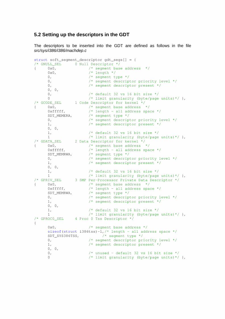
5.2 Setting up the descriptors in the GDT The descriptors to be inserted into the GDT are defined as follows in the file src/sys/i386/i386/machdep.c struct soft_segment_descriptor gdt_segs[] = { /* GNULL_SEL 0 Null Descriptor */ { 0x0, /* segment base address */ 0x0, /* length */ 0, /* segment type */ 0, /* segment descriptor priority level */ 0, /* segment descriptor present */ 0, 0, 0, /* default 32 vs 16 bit size */ 0 /* limit granularity (byte/page units)*/ }, /* GCODE_SEL 1 Code Descriptor for kernel */ { 0x0, /* segment base address */ 0xfffff, /* length - all address space */ SDT_MEMERA, /* segment type */ 0, /* segment descriptor priority level */ 1, /* segment descriptor present */ 0, 0, 1, /* default 32 vs 16 bit size */ 1 /* limit granularity (byte/page units)*/ }, /* GDATA_SEL 2 Data Descriptor for kernel */ { 0x0, /* segment base address */ 0xfffff, /* length - all address space */ SDT_MEMRWA, /* segment type */ 0, /* segment descriptor priority level */ 1, /* segment descriptor present */ 0, 0, 1, /* default 32 vs 16 bit size */ 1 /* limit granularity (byte/page units)*/ }, /* GPRIV_SEL 3 SMP Per-Processor Private Data Descriptor */ { 0x0, /* segment base address */ 0xfffff, /* length - all address space */ SDT_MEMRWA, /* segment type */ 0, /* segment descriptor priority level */ 1, /* segment descriptor present */ 0, 0, 1, /* default 32 vs 16 bit size */ 1 /* limit granularity (byte/page units)*/ }, /* GPROC0_SEL 4 Proc 0 Tss Descriptor */ { 0x0, /* segment base address */ sizeof(struct i386tss)-1,/* length - all address space */ SDT_SYS386TSS, /* segment type */ 0, /* segment descriptor priority level */ 1, /* segment descriptor present */ 0, 0, 0, /* unused - default 32 vs 16 bit size */ 0 /* limit granularity (byte/page units)*/ },
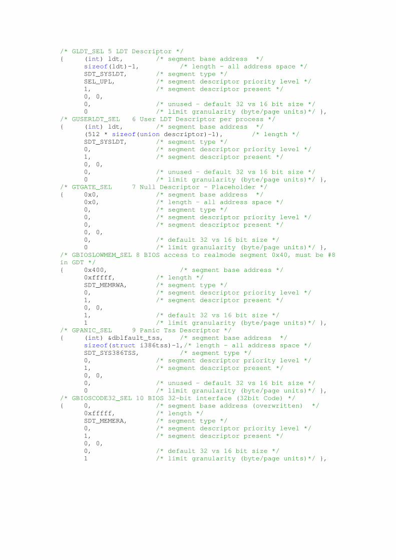
/* GLDT_SEL 5 LDT Descriptor */ { (int) ldt, /* segment base address */ sizeof(ldt)-1, /* length - all address space */ SDT_SYSLDT, /* segment type */ SEL_UPL, /* segment descriptor priority level */ 1, /* segment descriptor present */ 0, 0, 0, /* unused - default 32 vs 16 bit size */ 0 /* limit granularity (byte/page units)*/ }, /* GUSERLDT_SEL 6 User LDT Descriptor per process */ { (int) ldt, /* segment base address */ (512 * sizeof(union descriptor)-1), /* length */ SDT_SYSLDT, /* segment type */ 0, /* segment descriptor priority level */ 1, /* segment descriptor present */ 0, 0, 0, /* unused - default 32 vs 16 bit size */ 0 /* limit granularity (byte/page units)*/ }, /* GTGATE_SEL 7 Null Descriptor - Placeholder */ { 0x0, /* segment base address */ 0x0, /* length - all address space */ 0, /* segment type */ 0, /* segment descriptor priority level */ 0, /* segment descriptor present */ 0, 0, 0, /* default 32 vs 16 bit size */ 0 /* limit granularity (byte/page units)*/ }, /* GBIOSLOWMEM_SEL 8 BIOS access to realmode segment 0x40, must be #8 in GDT */ { 0x400, /* segment base address */ 0xfffff, /* length */ SDT_MEMRWA, /* segment type */ 0, /* segment descriptor priority level */ 1, /* segment descriptor present */ 0, 0, 1, /* default 32 vs 16 bit size */ 1 /* limit granularity (byte/page units)*/ }, /* GPANIC_SEL 9 Panic Tss Descriptor */ { (int) &dblfault_tss, /* segment base address */ sizeof(struct i386tss)-1,/* length - all address space */ SDT_SYS386TSS, /* segment type */ 0, /* segment descriptor priority level */ 1, /* segment descriptor present */ 0, 0, 0, /* unused - default 32 vs 16 bit size */ 0 /* limit granularity (byte/page units)*/ }, /* GBIOSCODE32_SEL 10 BIOS 32-bit interface (32bit Code) */ { 0, /* segment base address (overwritten) */ 0xfffff, /* length */ SDT_MEMERA, /* segment type */ 0, /* segment descriptor priority level */ 1, /* segment descriptor present */ 0, 0, 0, /* default 32 vs 16 bit size */ 1 /* limit granularity (byte/page units)*/ },
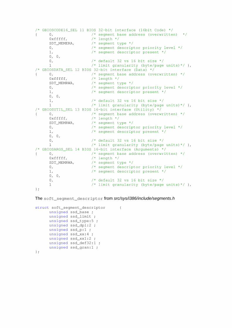
/* GBIOSCODE16_SEL 11 BIOS 32-bit interface (16bit Code) */ { 0, /* segment base address (overwritten) */ 0xfffff, /* length */ SDT_MEMERA, /* segment type */ 0, /* segment descriptor priority level */ 1, /* segment descriptor present */ 0, 0, 0, /* default 32 vs 16 bit size */ 1 /* limit granularity (byte/page units)*/ }, /* GBIOSDATA_SEL 12 BIOS 32-bit interface (Data) */ { 0, /* segment base address (overwritten) */ 0xfffff, /* length */ SDT_MEMRWA, /* segment type */ 0, /* segment descriptor priority level */ 1, /* segment descriptor present */ 0, 0, 1, /* default 32 vs 16 bit size */ 1 /* limit granularity (byte/page units)*/ }, /* GBIOSUTIL_SEL 13 BIOS 16-bit interface (Utility) */ { 0, /* segment base address (overwritten) */ 0xfffff, /* length */ SDT_MEMRWA, /* segment type */ 0, /* segment descriptor priority level */ 1, /* segment descriptor present */ 0, 0, 0, /* default 32 vs 16 bit size */ 1 /* limit granularity (byte/page units)*/ }, /* GBIOSARGS_SEL 14 BIOS 16-bit interface (Arguments) */ { 0, /* segment base address (overwritten) */ 0xfffff, /* length */ SDT_MEMRWA, /* segment type */ 0, /* segment descriptor priority level */ 1, /* segment descriptor present */ 0, 0, 0, /* default 32 vs 16 bit size */ 1 /* limit granularity (byte/page units)*/ }, }; The soft_segment_descriptor from src/sys/i386/include/segments.h struct soft_segment_descriptor { unsigned ssd_base ; unsigned ssd_limit ; unsigned ssd_type:5 ; unsigned ssd_dpl:2 ; unsigned ssd_p:1 ; unsigned ssd_xx:4 ; unsigned ssd_xx1:2 ; unsigned ssd_def32:1 ; unsigned ssd_gran:1 ; };

The code that actually sets up the GDT is only a few lines long when stripped down to the central parts From src/sys/i386/i386/machdep.c gdt_segs[GCODE_SEL].ssd_limit = atop(0 - 1); gdt_segs[GDATA_SEL].ssd_limit = atop(0 - 1); . . . gdt_segs[GPRIV_SEL].ssd_limit = atop(0 - 1); gdt_segs[GPROC0_SEL].ssd_base = (int) &common_tss; for (x = 0; x < NGDT; x++) { . . . ssdtosd(&gdt_segs[x], &gdt[x].sd); } r_gdt.rd_limit = NGDT * sizeof(gdt[0]) - 1; r_gdt.rd_base = (int) gdt; lgdt(&r_gdt); First we need to understand what atop(0 - 1) stands for. The (0 - 1) part evaluates to –1, which is represented as 32 bits of only 1’s. Next we take a look at the atop macro in src/sys/i386/include/param.h #define atop(x) ((x) >> PAGE_SHIFT) #define PAGE_SHIFT 12 The limit granularity is set to 1 in all the segment descriptors, that is, 4096 byte pages. So we have to shift the value of (0 – 1) 12 positions to the right to get the limit in pages. What this means is that the segments cover the whole address space. The for loop inserts the descriptors into the GDT. We will not study the copy function ssdtosd any closer since it is pretty straightforward.
5.3 Making the GDT active The last few lines of code are similar to the ones that activate the IDT r_gdt.rd_limit = NGDT * sizeof(gdt[0]) - 1; r_gdt.rd_base = (int) gdt; lgdt(&r_gdt); We already know how the ENTRY macro works. ENTRY(lgdt) The actual loading of the GDTR is straightforward. movl 4(%esp),%eax lgdt (%eax)
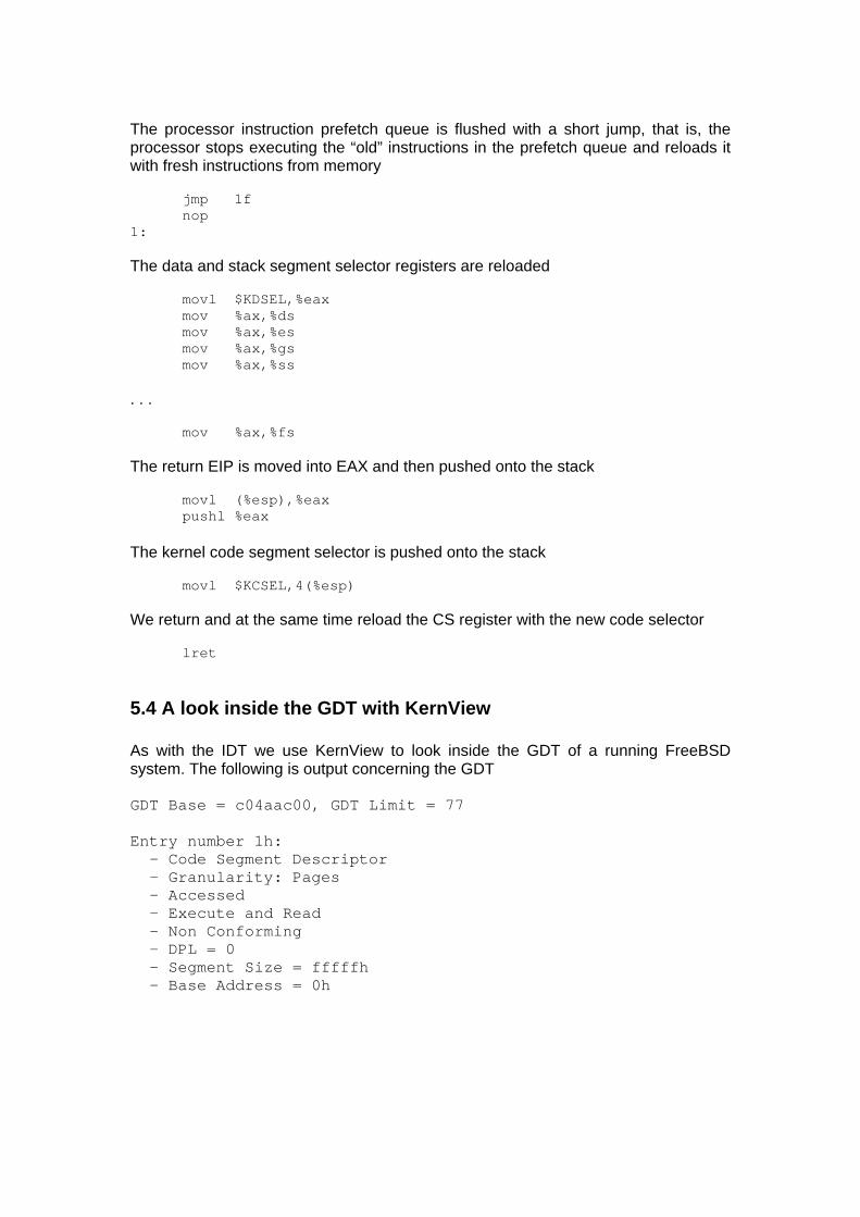
The processor instruction prefetch queue is flushed with a short jump, that is, the processor stops executing the “old” instructions in the prefetch queue and reloads it with fresh instructions from memory jmp 1f nop 1: The data and stack segment selector registers are reloaded movl $KDSEL,%eax mov %ax,%ds mov %ax,%es mov %ax,%gs mov %ax,%ss . . . mov %ax,%fs The return EIP is moved into EAX and then pushed onto the stack movl (%esp),%eax pushl %eax The kernel code segment selector is pushed onto the stack movl $KCSEL,4(%esp) We return and at the same time reload the CS register with the new code selector lret
5.4 A look inside the GDT with KernView As with the IDT we use KernView to look inside the GDT of a running FreeBSD system. The following is output concerning the GDT GDT Base = c04aac00, GDT Limit = 77 Entry number 1h: - Code Segment Descriptor - Granularity: Pages - Accessed - Execute and Read - Non Conforming - DPL = 0 - Segment Size = fffffh - Base Address = 0h
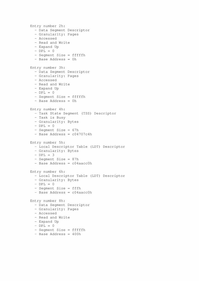
Entry number 2h: - Data Segment Descriptor - Granularity: Pages - Accessed - Read and Write - Expand Up - DPL = 0 - Segment Size = fffffh - Base Address = 0h Entry number 3h: - Data Segment Descriptor - Granularity: Pages - Accessed - Read and Write - Expand Up - DPL = 0 - Segment Size = fffffh - Base Address = 0h Entry number 4h: - Task State Segment (TSS) Descriptor - Task is Busy - Granularity: Bytes - DPL = 0 - Segment Size = 67h - Base Address = c04707c4h Entry number 5h: - Local Descriptor Table (LDT) Descriptor - Granularity: Bytes - DPL = 3 - Segment Size = 87h - Base Address = c04aacc0h Entry number 6h: - Local Descriptor Table (LDT) Descriptor - Granularity: Bytes - DPL = 0 - Segment Size = fffh - Base Address = c04aacc0h Entry number 8h: - Data Segment Descriptor - Granularity: Pages - Accessed - Read and Write - Expand Up - DPL = 0 - Segment Size = fffffh - Base Address = 400h
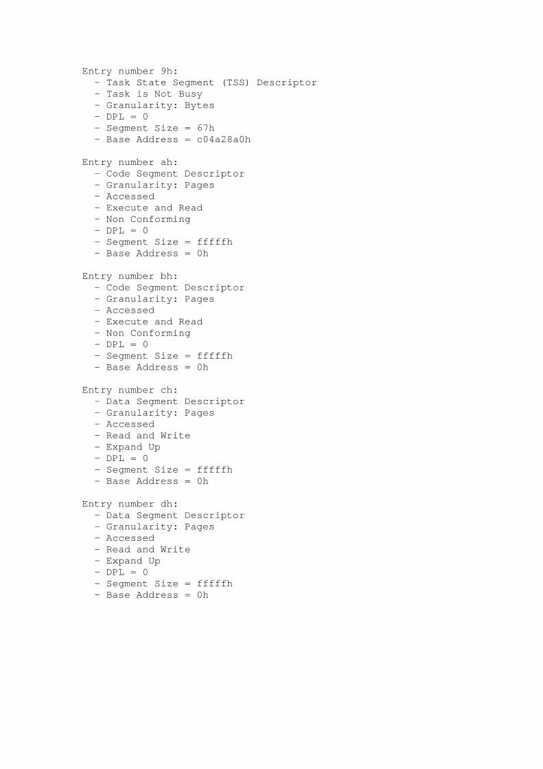
Entry number 9h: - Task State Segment (TSS) Descriptor - Task is Not Busy - Granularity: Bytes - DPL = 0 - Segment Size = 67h - Base Address = c04a28a0h Entry number ah: - Code Segment Descriptor - Granularity: Pages - Accessed - Execute and Read - Non Conforming - DPL = 0 - Segment Size = fffffh - Base Address = 0h Entry number bh: - Code Segment Descriptor - Granularity: Pages - Accessed - Execute and Read - Non Conforming - DPL = 0 - Segment Size = fffffh - Base Address = 0h Entry number ch: - Data Segment Descriptor - Granularity: Pages - Accessed - Read and Write - Expand Up - DPL = 0 - Segment Size = fffffh - Base Address = 0h Entry number dh: - Data Segment Descriptor - Granularity: Pages - Accessed - Read and Write - Expand Up - DPL = 0 - Segment Size = fffffh - Base Address = 0h
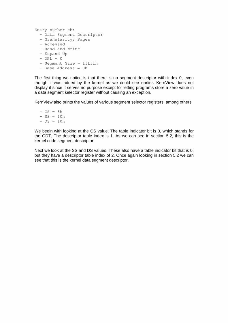
Entry number eh: - Data Segment Descriptor - Granularity: Pages - Accessed - Read and Write - Expand Up - DPL = 0 - Segment Size = fffffh - Base Address = 0h
The first thing we notice is that there is no segment descriptor with index 0, even though it was added by the kernel as we could see earlier. KernView does not display it since it serves no purpose except for letting programs store a zero value in a data segment selector register without causing an exception. KernView also prints the values of various segment selector registers, among others - CS = 8h - SS = 10h - DS = 10h We begin with looking at the CS value. The table indicator bit is 0, which stands for the GDT. The descriptor table index is 1. As we can see in section 5.2, this is the kernel code segment descriptor. Next we look at the SS and DS values. These also have a table indicator bit that is 0, but they have a descriptor table index of 2. Once again looking in section 5.2 we can see that this is the kernel data segment descriptor.
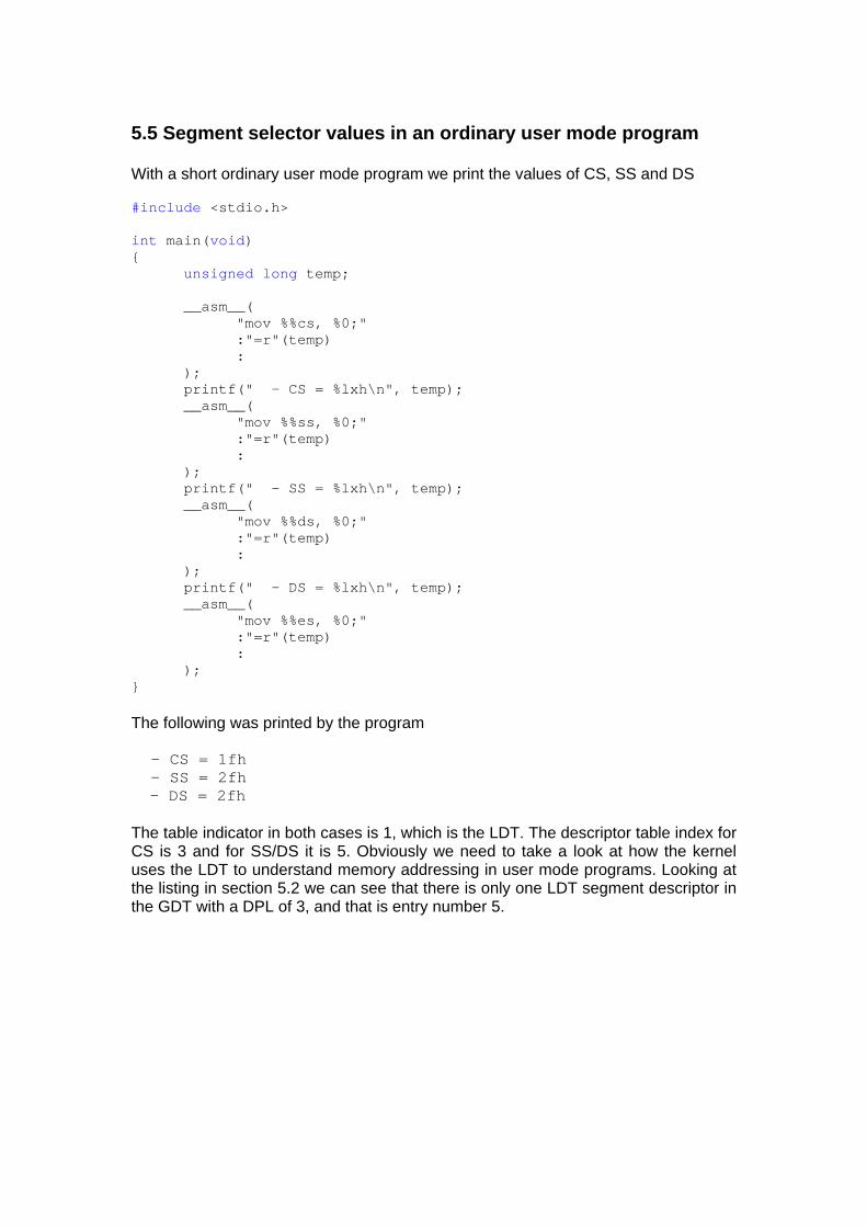
5.5 Segment selector values in an ordinary user mode program With a short ordinary user mode program we print the values of CS, SS and DS #include <stdio.h> int main(void) { unsigned long temp; __asm__( "mov %%cs, %0;" :"=r"(temp) : ); printf(" - CS = %lxh\n", temp); __asm__( "mov %%ss, %0;" :"=r"(temp) : ); printf(" - SS = %lxh\n", temp); __asm__( "mov %%ds, %0;" :"=r"(temp) : ); printf(" - DS = %lxh\n", temp); __asm__( "mov %%es, %0;" :"=r"(temp) : ); } The following was printed by the program - CS = 1fh - SS = 2fh - DS = 2fh
The table indicator in both cases is 1, which is the LDT. The descriptor table index for CS is 3 and for SS/DS it is 5. Obviously we need to take a look at how the kernel uses the LDT to understand memory addressing in user mode programs. Looking at the listing in section 5.2 we can see that there is only one LDT segment descriptor in the GDT with a DPL of 3, and that is entry number 5.

We run another short user mode program to determine the value in LDTR. #include <stdio.h> int main(void) { unsigned short temp; __asm__( "sldt %0;" :"=m"(temp) : ); printf(" - (LDTR) LDT Selector = %xh\n", temp); }
- (LDTR) LDT Selector = 28h The LDTR has a table indicator of 0 (the GDT) and a descriptor table index of 5. This corresponds with what we observed earlier. As is well known, when the processor performs a hardware supported task switch it updates the LDTR with the LDT segment selector value from the tasks TSS (Task State Segment). Since we could only see one LDT segment descriptor in the GDT we can conclude that the FreeBSD kernel does not fully utilize hardware supported task switching. Next we will look at how its soft task switching is implemented.
6. Task switching
6.1 The cpu_switch() function The cpu_switch() function is responsible for saving the context of the running process and letting a new process run. We will look at the function from top to bottom and with only the SMP handling and the FPU state save code stripped out. From src/sys/i386/i386/swtch.s ENTRY(cpu_switch) First we check if we have been executing another process or not. If not we do not have to save process state before going on to the new process movl _curproc,%ecx
testl %ecx,%ecx je sw1
The following lines of code are a little bit harder to figure out . . . movl P_VMSPACE(%ecx), %edx . . . xorl %eax, %eax btrl %eax, VM_PMAP+PM_ACTIVE(%edx) From src/sys/i386/i386/genassym.c ASSYM(P_VMSPACE, offsetof(struct proc, p_vmspace)); ASSYM(VM_PMAP, offsetof(struct vmspace, vm_pmap)); ASSYM(PM_ACTIVE, offsetof(struct pmap, pm_active)); In other words, P_VMSPACE represents the offset of the p_vmspace member in the proc structure, and VM_PMAP represents the offset of the vm_pmap member in the vmspace structure. Finally, PM_ACTIVE is the offset of the pm_active member in the pmap structure. When we begin, ECX contains the address of the proc structure of the currently running process. The following line puts the address of the p_vmspace member into the EDX register movl P_VMSPACE(%ecx), %edx Next, EAX is zeroed xorl %eax, %eax Then we perform a bit test and reset instruction, of which we only use the reset part btrl %eax, VM_PMAP+PM_ACTIVE(%edx) The zero in EAX means that we work with bit 0 in VM_PMAP+PM_ACTIVE(%edx). But what does that last part stand for? VM_PMAP makes sure that we get to the vm_pmap member of the p_vmspace pointed to by the EDX register. Then, PM_ACTIVE gets us to the pm_active member of that member. So we reset bit 0 of pm_active. This marks the private physical map as not being active on any CPU of the system. Now we can go on with the next instruction movl P_ADDR(%ecx),%edx

From src/sys/i386/i386/genassym.c ASSYM(P_ADDR, offsetof(struct proc, p_addr)); Thus, the address of the member p_addr of proc structure of the currently running process is put in the EDX register. This member is a pointer to the user structure of the process in question. For each process the kernel keeps two structures, the proc structure and the user structure. From the beginning the proc structure stored everything about a process that needed to be accessible even when it was paged out. The user structure contained those things that were allowed to be paged out. Nowadays the division is not that strict. Anyway, the user structure contains the Process Control Block (PCB), which in turn contains the execution state of the process. This is where we will store the values of the various processor registers. Before moving on to that code, we take a look at both of the structures From src/sys/sys/user.h struct user { struct pcb u_pcb; struct sigacts u_sigacts; struct pstats u_stats; struct kinfo_proc u_kproc; struct md_coredump u_md; }; From src/sys/i386/include/pcb.h with SMP code removed struct pcb { int pcb_cr3; int pcb_edi; int pcb_esi; int pcb_ebp; int pcb_esp; int pcb_ebx; int pcb_eip; int pcb_dr0; int pcb_dr1; int pcb_dr2; int pcb_dr3; int pcb_dr6; int pcb_dr7; #ifdef USER_LDT struct pcb_ldt *pcb_ldt; #else struct pcb_ldt *pcb_ldt_dontuse; #endif union savefpu pcb_save; u_char pcb_flags; caddr_t pcb_onfault; u_long pcb_mpnest_dontuse; int pcb_gs; struct pcb_ext *pcb_ext; u_long __pcb_spare[3]; };
There is really not much to say about the following code. It simply saves the process register context into the PCB movl (%esp),%eax movl %eax,PCB_EIP(%edx) movl %ebx,PCB_EBX(%edx) movl %esp,PCB_ESP(%edx) movl %ebp,PCB_EBP(%edx) movl %esi,PCB_ESI(%edx) movl %edi,PCB_EDI(%edx) movl %gs,PCB_GS(%edx) movb PCB_FLAGS(%edx),%al andb $PCB_DBREGS,%al jz 1f movl %dr7,%eax movl %eax,PCB_DR7(%edx) andl $0x0000fc00, %eax movl %eax,%dr7 movl %dr6,%eax movl %eax,PCB_DR6(%edx) movl %dr3,%eax movl %eax,PCB_DR3(%edx) movl %dr2,%eax movl %eax,PCB_DR2(%edx) movl %dr1,%eax movl %eax,PCB_DR1(%edx) movl %dr0,%eax movl %eax,PCB_DR0(%edx) 1: . . . Finally, we set the current process to 0, meaning that we are not executing any user mode process at the moment movl $0,_curproc We are done working with the formerly current process and now we go on with selecting a new process to run. The code used to select a new process is out of the scope of this guide so we skip it sw1: cli . . . sw1a: call _chooseproc testl %eax,%eax CROSSJUMP(je, _idle, jne) movl %eax,%ecx xorl %eax,%eax andl $~AST_RESCHED,_astpending . . .
The address of the proc structure of the new process has been stored in ECX. movl P_ADDR(%ecx),%edx . . . If the page table directory base address for the new process to run is the same as is already in CR3, then skip setting a new one movl %cr3,%ebx cmpl PCB_CR3(%edx),%ebx je 4f . . . Get the page table directory base address for the new process to run from its PCB and put it in CR3 movl PCB_CR3(%edx),%ebx movl %ebx,%cr3 4: xorl %esi, %esi Is there a PCB extension present? This means that each process has its own TSS cmpl $0, PCB_EXT(%edx) je 1f The _private_tss variable is a flag that indicates the use of a private TSS, and the next line of code sets bit 0 btsl %esi, _private_tss The following instruction retrieves the address of the TSS descriptor stored in the extended PCB. PCB_EXT gets us to the extended PCB structure and the TSS descriptor is the first member so we do not need any additional offset to get to it movl PCB_EXT(%edx), %edi jmp 2f There is no PCB extension present so the process has to use a shared TSS. Load the address of the PCB into EBX 1: movl %edx, %ebx From src/sys/i386/include/param.h #define UPAGES 3 This is the number of pages that the u-area uses, so the following line adds the number of bytes in the pages that the u-area uses minus 2 bytes addl $(UPAGES * PAGE_SIZE - 16), %ebx
This value is then used in the following line movl %ebx, _common_tss + TSS_ESP0 TSS_ESP0 stands for the offset of the member tss_esp in the structure i386tss. ESP0 is the ring 0 stack pointer. Reset bit 0 of _private_tss, that is, reset the flag to show that we do not use a private TSS btrl %esi, _private_tss jae 3f Put the address of the common TSS descriptor into EDI movl $_common_tssd, %edi 2: Put the TSS descriptor into the GDT movl _tss_gdt, %ebx movl 0(%edi), %eax movl %eax, 0(%ebx) movl 4(%edi), %eax movl %eax, 4(%ebx) GPROC0_SEL is a constant with the value 4, so the following line creates a segment selector that points out descriptor number 4 in the GDT movl $GPROC0_SEL*8, %esi Load it into the task register ltr %si This marks the private physical map as being active on any CPU of the system. We have already studied the opposite earlier in this section 3: movl P_VMSPACE(%ecx), %ebx xorl %eax, %eax btsl %eax, VM_PMAP+PM_ACTIVE(%ebx) We restore various processor registers movl PCB_EBX(%edx),%ebx movl PCB_ESP(%edx),%esp movl PCB_EBP(%edx),%ebp movl PCB_ESI(%edx),%esi movl PCB_EDI(%edx),%edi movl PCB_EIP(%edx),%eax movl %eax,(%esp) . . .
We also set a couple of variables to new values movl %edx, _curpcb movl %ecx, _curproc . . . If the kernel has been compiled with options USER_LDT, a process can get and set its own LDT. The i386_get_ldt() system call returns the list of descriptors in the LDT. The i386_set_ldt() system call puts a list of descriptors into the LDT. #ifdef USER_LDT Check if the process has a user LDT set or not cmpl $0, PCB_USERLDT(%edx) jnz 1f It did not have a user LDT so set the default one movl __default_ldt,%eax If the current LDT is the same as the default we do not have to load the LDTR cmpl _currentldt,%eax je 2f Load the LDTR and set the current LDT lldt __default_ldt movl %eax,_currentldt jmp 2f The process already had a user LDT, so we have to insert a LDT descriptor into the GDT. The function for doing that is very simple and inserts the LDT descriptor at position GUSERLDT_SEL, which is defined as 6. If we go back to section 5.4 we see in the KernView output that position 6 is a LDT descriptor. There are only two LDT descriptors in the GDT, and we have already looked at the other one in section 5.5. 1: pushl %edx call _set_user_ldt popl %edx 2: #endif .globl cpu_switch_load_gs cpu_switch_load_gs:
Next we restore various processor registers and return, which starts the new process movl PCB_GS(%edx),%gs movb PCB_FLAGS(%edx),%al andb $PCB_DBREGS,%al jz 1f movl PCB_DR6(%edx),%eax movl %eax,%dr6 movl PCB_DR3(%edx),%eax movl %eax,%dr3 movl PCB_DR2(%edx),%eax movl %eax,%dr2 movl PCB_DR1(%edx),%eax movl %eax,%dr1 movl PCB_DR0(%edx),%eax movl %eax,%dr0 movl %dr7,%eax andl $0x0000fc00,%eax pushl %ebx movl PCB_DR7(%edx),%ebx andl $~0x0000fc00,%ebx orl %ebx,%eax popl %ebx movl %eax,%dr7 1: sti ret
7. Virtual paging
7.1 The page fault handler From src/sys/i386/i386/machdep.c setidt(14, &IDTVEC(page), SDT_SYS386IGT, SEL_KPL, GSEL(GCODE_SEL, SEL_KPL)); This line of code is quite similar to the one that set the INT 0x80 entry in the IDT, so we will skip many of the details this time. The parameter &IDTVEC(page) can be read out as &Xpage, which is the address of the page fault handler. The third parameter is the constant SDT_SYS386IGT, meaning that this gate is an interrupt gate. The fourth parameter is the constant SEL_KPL, which means that the page fault handler may only be invoked from any ring.
The fifth argument, GSEL(GCODE_SEL, SEL_KPL) is the selector for the segment where the page fault handler resides. The descriptor table index in this case is 1. As can be seen in the section about the GDT, this is the index to the kernel code segment descriptor. The table indicator will be 0, meaning that the GDT is to be used. Now we look in src/sys/i386/i386/exception.s IDTVEC(page) TRAP(T_PAGEFLT) In the same file we find #define TRAP(a) pushl $(a) ; jmp _alltraps We also find SUPERALIGN_TEXT .globl _alltraps .type _alltraps,@function _alltraps: pushal pushl %ds pushl %es pushl %fs . . . mov $KDSEL,%ax mov %ax,%ds mov %ax,%es MOVL_KPSEL_EAX mov %ax,%fs . . . movl _cpl,%ebx call _trap . . . Since we have already studied this type of code before, we move on straight to the _trap() function. In src/sys/i386/include/asnames.h we find #define _trap trap
Moving on to src/sys/i386/i386/trap.c we find the following void trap(frame) struct trapframe frame; { . . . if (frame.tf_trapno == T_PAGEFLT) { eva = rcr2(); . . . switch (type) { case T_PAGEFLT: /* page fault */ (void) trap_pfault(&frame, FALSE, eva); return; . . . The trap() function is long and most of it has nothing to do with page faults, so we just notice that the variable eva is loaded with the value in the CR2 register (page fault linear address), then we go on to the trap_pfault function. From src/sys/i386/i386/trap.c int trap_pfault(frame, usermode, eva) struct trapframe *frame; int usermode; vm_offset_t eva; { . . . struct proc *p = curproc; . . . va = trunc_page(eva); . . . vm = p->p_vmspace; . . . map = &vm->vm_map; rv = vm_fault(map, va, ftype, (ftype & VM_PROT_WRITE) ? VM_FAULT_DIRTY : VM_FAULT_NORMAL); The trap_pfault() function contains a lot of code, most of which has been cut out above, but since this guide is not about memory management we stop here. The vm_fault() function is the one that is responsible for loading the paged out page from disk into the primary memory.
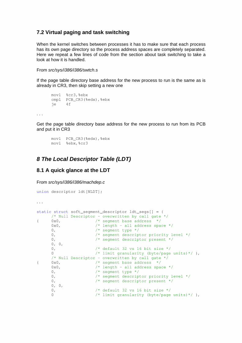
7.2 Virtual paging and task switching When the kernel switches between processes it has to make sure that each process has its own page directory so the process address spaces are completely separated. Here we repeat a few lines of code from the section about task switching to take a look at how it is handled. From src/sys/i386/i386/swtch.s If the page table directory base address for the new process to run is the same as is already in CR3, then skip setting a new one movl %cr3,%ebx cmpl PCB_CR3(%edx),%ebx je 4f . . . Get the page table directory base address for the new process to run from its PCB and put it in CR3 movl PCB_CR3(%edx),%ebx movl %ebx,%cr3
8 The Local Descriptor Table (LDT)
8.1 A quick glance at the LDT From src/sys/i386/i386/machdep.c union descriptor ldt[NLDT]; . . . static struct soft_segment_descriptor ldt_segs[] = { /* Null Descriptor - overwritten by call gate */ { 0x0, /* segment base address */ 0x0, /* length - all address space */ 0, /* segment type */ 0, /* segment descriptor priority level */ 0, /* segment descriptor present */ 0, 0, 0, /* default 32 vs 16 bit size */ 0 /* limit granularity (byte/page units)*/ }, /* Null Descriptor - overwritten by call gate */ { 0x0, /* segment base address */ 0x0, /* length - all address space */ 0, /* segment type */ 0, /* segment descriptor priority level */ 0, /* segment descriptor present */ 0, 0, 0, /* default 32 vs 16 bit size */ 0 /* limit granularity (byte/page units)*/ },
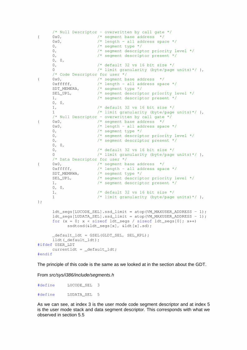
/* Null Descriptor - overwritten by call gate */ { 0x0, /* segment base address */ 0x0, /* length - all address space */ 0, /* segment type */ 0, /* segment descriptor priority level */ 0, /* segment descriptor present */ 0, 0, 0, /* default 32 vs 16 bit size */ 0 /* limit granularity (byte/page units)*/ }, /* Code Descriptor for user */ { 0x0, /* segment base address */ 0xfffff, /* length - all address space */ SDT_MEMERA, /* segment type */ SEL_UPL, /* segment descriptor priority level */ 1, /* segment descriptor present */ 0, 0, 1, /* default 32 vs 16 bit size */ 1 /* limit granularity (byte/page units)*/ }, /* Null Descriptor - overwritten by call gate */ { 0x0, /* segment base address */ 0x0, /* length - all address space */ 0, /* segment type */ 0, /* segment descriptor priority level */ 0, /* segment descriptor present */ 0, 0, 0, /* default 32 vs 16 bit size */ 0 /* limit granularity (byte/page units)*/ }, /* Data Descriptor for user */ { 0x0, /* segment base address */ 0xfffff, /* length - all address space */ SDT_MEMRWA, /* segment type */ SEL_UPL, /* segment descriptor priority level */ 1, /* segment descriptor present */ 0, 0, 1, /* default 32 vs 16 bit size */ 1 /* limit granularity (byte/page units)*/ }, }; ldt_segs[LUCODE_SEL].ssd_limit = atop(VM_MAXUSER_ADDRESS - 1); ldt_segs[LUDATA_SEL].ssd_limit = atop(VM_MAXUSER_ADDRESS - 1); for (x = 0; x < sizeof ldt_segs / sizeof ldt_segs[0]; x++) ssdtosd(&ldt_segs[x], &ldt[x].sd); _default_ldt = GSEL(GLDT_SEL, SEL_KPL); lldt(_default_ldt); #ifdef USER_LDT currentldt = _default_ldt; #endif The principle of this code is the same as we looked at in the section about the GDT. From src/sys/i386/include/segments.h #define LUCODE_SEL 3 #define LUDATA_SEL 5 As we can see, at index 3 is the user mode code segment descriptor and at index 5 is the user mode stack and data segment descriptor. This corresponds with what we observed in section 5.5
In section 7.1 we looked at how the LDT is handled by the FreeBSD kernel’s soft task switching.
9. Miscellaneous
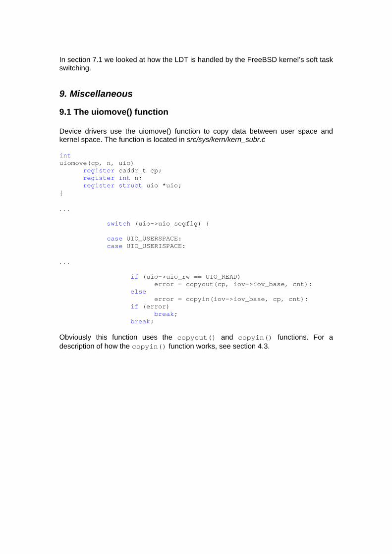
9.1 The uiomove() function Device drivers use the uiomove() function to copy data between user space and kernel space. The function is located in src/sys/kern/kern_subr.c int uiomove(cp, n, uio) register caddr_t cp; register int n; register struct uio *uio; { . . . switch (uio->uio_segflg) { case UIO_USERSPACE: case UIO_USERISPACE: . . . if (uio->uio_rw == UIO_READ) error = copyout(cp, iov->iov_base, cnt); else error = copyin(iov->iov_base, cp, cnt); if (error) break; break; Obviously this function uses the copyout() and copyin() functions. For a description of how the copyin() function works, see section 4.3.