a glimpse of architecture_christa trautman
DESCRIPTION
A comprehensive work sample from my undergraduate studies at the University at Buffalo SA+P.TRANSCRIPT
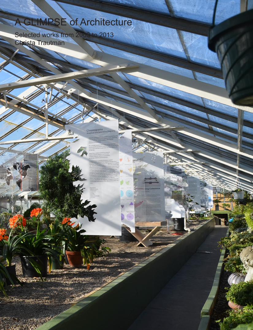
A GLIMPSE of ArchitectureSelected works from 2009 to 2013Christa Trautman


QualificationsProficient in Autocad, Rhino, the Adobe Suite, and Microsoft OfficeBasic knowledge of 3ds Max, Revit, Grasshopper, and Google Sketchup
Work HistoryHostess at Merge, 439 Delaware Ave. April 2013 to present Answering phones, seating and bussing tables, general customer serviceFabrication Lab Employee at Buffalo Fabrication, UB South Campus August 2012 to December 2012 Running laser cutting machinery, answering phones, trouble shooting and assisting studentsIntern, Facilities Planning, Roswell Park Cancer Institute May 2011 to August 2011 Shadowing meetings and site visits, drafting, and hand renderingResearch Apprentice, Cell Stress Biology, Roswell Park Cancer Institute June 2010 to August 2011 Clerical work, assisting with payroll, answering phones, escorting guest speakersHostess + Customer Service Representative, Muscoreil’s Italian Bakery June 2006 to August 2010 Waiting on customers, answering phoes, completing custom cake orders, general upkeep of the store front
EducationB.S. Architecture Cum Laude, Univeristy at Buffalo August 2009 to May 2013Advanced Regents Diploma, Starpoint Central Highschool September 2005 to June 2009
Extracurricular WorkLife Cycles Exhibition, Buffalo + Erie County Botanical Gardens, Buffalo, NY March 2013, group exhibitionSustainable Futures study abroad, Monteverde Institute, Monteverde, Costa Rica May - August 2012Infrastructural Research Symposium, CEPA Gallery, Buffalo, NY April 2012, student work shown in collaboration with Curt GambettaAIAS Buffalo Chapter President 2011Habitat for Humanity Women’s Build, Fox St. Buffalo, NY May 2010
Curriculum Vitae

2368
1012

Life CyclesAn exhibition at the BECBG
Construction Technology AxonometricPierce County Environmental Services Building by Miller Hull Partnership
Carving CoherenceAn extension to the BECBG
Complementary SystemsCore and shell office + fish market
The Living WallThe Shield
Fluid ConnectionsMulti-generational housing + public pool

Conceptual Model
Spring 2013 Arc 302 coordinator Jordan Geiger professor Brad Wales & Nerea Feliz
The Erie County + Buffalo Botanical Gardens was interested in exhibiting proposals developed from the Sping 2012 studio. The exhibition was developed to involve the public in the possibilities for expansion. The projects are currently used a starting point for the gardens to begin a capital campaign for a new addition and renovation to their historic structure. The exhibit was held in the gardens from March 15th to April 7th of 2013.
Life CyclesAn exhibition at the BECBG

ADDITION: a part added EXTENSION: an enlargement in scope or operation; a property whereby something occupies space; a program that
geographically extends the educational resources of an institution by special arrangements to persons RENOVATION: to restore to life, vigor, or activity;
revive SERE: a series of ecological communities formed in ecological succession DEPENDENT: relying on another for support SUPPORT: to
promote the interests or cause of; to assist, help; to maintain, pay the costs of; to hold up or serve as a foundation or prop
for; to keep (something) going BIFURCATE: to cause to divide into two branches or parts NE PLUS ULTRA:the highest point
capable of being attaineda branch
of science concerned with the interrelationships of organisms
and their environments
ECOLOGICAL:
INTERSECT: to share a common area; overlap CULTIVATE: to foster the growth of; culture FOSTER:
affording, recieving, or sharing nurture or parental care though not related by blood or legal ties ANTHROPOGENIC:
of, relating to, or resulting from the infl uence of human beings on nature SUSTAINABLE: capable of being sustained; of, relating to, or being a method of harvesting or using a resource so that the resource
is not depleted or permanently damaged SUSTAIN:to give support or relief to; to supply with sustenance: Nourish; prolong
of or relating to Malthus or to his theory that popula-tion tends to increase at a faster rate than its means of subsistence and that unless it
is checked by moral restraint or disaster (disease, famine, or war) widespreadpoverty and degradation inevitably result
“The power of population is indefi nitely greater than the power in the earth to produce subsitence for man... the superior power of population cannot go
unchecked without producing misery or vice.” Thomas MalthusGlobal Warming: an increase in the earth’s atmospheric and oceanic
temperatures widely predicted to occur due to an increase in the greenhouse effectresulting especially from pollution; to be associated especially with the side effects of
recent human activity such as the increased production of greenhouse gases; if left unchecked will cause pervasive natural disasters and species
extinction;“In a state therefore of great equality and virtue, where pure and simple manners prevailed the increase of the human species would evidently be much
greater than any increase that has hitherto been known.” Thomas Malthus
MALTHUSIAN:
Conceptually, the destruction of global weather systems,global warming,could be seen as an antithesis of coherence.
C O H E R E N C Eintegration of diverse elements, relationships or values; logical or
natural connection or consistency; consistency in reasoning, or relating so that one part of the discourse does not destroy or contradict the rest
Programmatic Relationships + Associated Effects
Carving Coherence seeks to unite the diverse elements of the Buffalo Botanical Gardens into one [coherent] entity. By mirroring the form of the Lord + Burnham structure into the earth, the project creates a strong formal connection between the existing and proposed structures. Furthermore, carving into the earth allows plants to grow to their natural heights without creating an addition that would overpower the historic facade that has been a [coherent] icon within the community for more than a century.
Carving CoherenceAn extension to the BECBG
Horticulture Education Weddings South Park
Admissions
Booking Events
Increasing Membership
Global Warming
Programmatic relationships & Associated effects
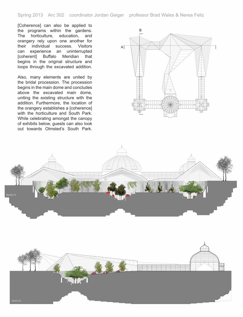
Section A
Section B
B
A
[Coherence] can also be applied to the programs within the gardens. The horticulture, education, and orangery rely upon one another for their individual success. Visitors can experience an uninterrupted [coherent] Buffalo Meridian that begins in the original structure and loops through the excavated addition.
Also, many elements are united by the bridal procession. The procession begins in the main dome and concludes above the excavated main dome, uniting the existing structure with the addition. Furthermore, the location of the orangery establishes a [coherence] with the horticulture and South Park. While celebrating amongst the canopy of exhibits below, guests can also look out towards Olmsted’s South Park.
Spring 2013 Arc 302 coordinator Jordan Geiger professor Brad Wales & Nerea Feliz

Interior Perspective of excavated gardens View from orangery to gardens below

Substructure:
Footing for Aluminum Storefront:
Footing for Concrete Beam:
Superstructure:
First Floor Assembly Type 1 Carpet Resillient Base Raised Floor System 4” Concrete Slab on Grade 2” Sand Vapor Barrier 4” Crushed Gravel R-10 Rigid Insulation at Perimeter
First Floor Assembly Type 3 Carpet Resilient Base 2” Concrete Topping Slab Radiant Heating System Cast in Place 4” Concrete Slab 4” Crushed Gravel Vapor Barrier R-10 Rigid Insulation at Perimeter and Underslab
Second Floor Assembly Type 3 Carpet Resilient Base 2” Concrete Topping Radiant Heating System Cast in Place 6” Concrete Slab
First and Second Floor Ceiling Fabric Ceiling System B.O. Concrete Structure 1” White Faced Acoustic Insulation Mechanical Sprinkler Piping Continuous 4” Metal Stud Framing at 16” o.c. Continuous .5” frt. Plywood Nailer Fabric
Aluminum Curtain Wall System Metal Studs Spandrel Glass
Cast in Place Concrete Beam and Columns Supporting Roof Overhang 3’ x 2’ 3.5” Cast in Place Concrete Beam 3 Rows of 7 #10 Reinforcing 18” Diameter Concrete Columns 8 #5 Reinforcing Placed 1.5” from perimeter
Roof Roo�ng Membrane .5” Pressure Treated Plywood 4.5” Insulation (U.N.O.) Hollow Core Concrete Plank 4’ x 10”
Pierce County Environmental Services BuildingMiller Hull Partnership
Sarah Mailloux, Nicole Nguyen, Shane Reidy, Christa Trautman
0 1 2 3 4 5 10
1
2
3
4
5
6
7
8
9
1
2
3
4
5
67
8
9
Technical axonometrics were redrafted from technical drawings to learn the basic processes of construction.
Spring 2011 Arc 442 professor Annette LeCuyer
Construction Technology AxonometricPierce County Environmental Services Building by Miller Hull Partnership

Substructure:
Footing for Aluminum Storefront:
Footing for Concrete Beam:
Superstructure:
First Floor Assembly Type 1 Carpet Resillient Base Raised Floor System 4” Concrete Slab on Grade 2” Sand Vapor Barrier 4” Crushed Gravel R-10 Rigid Insulation at Perimeter
First Floor Assembly Type 3 Carpet Resilient Base 2” Concrete Topping Slab Radiant Heating System Cast in Place 4” Concrete Slab 4” Crushed Gravel Vapor Barrier R-10 Rigid Insulation at Perimeter and Underslab
Second Floor Assembly Type 3 Carpet Resilient Base 2” Concrete Topping Radiant Heating System Cast in Place 6” Concrete Slab
First and Second Floor Ceiling Fabric Ceiling System B.O. Concrete Structure 1” White Faced Acoustic Insulation Mechanical Sprinkler Piping Continuous 4” Metal Stud Framing at 16” o.c. Continuous .5” frt. Plywood Nailer Fabric
Aluminum Curtain Wall System Metal Studs Spandrel Glass
Cast in Place Concrete Beam and Columns Supporting Roof Overhang 3’ x 2’ 3.5” Cast in Place Concrete Beam 3 Rows of 7 #10 Reinforcing 18” Diameter Concrete Columns 8 #5 Reinforcing Placed 1.5” from perimeter
Roof Roo�ng Membrane .5” Pressure Treated Plywood 4.5” Insulation (U.N.O.) Hollow Core Concrete Plank 4’ x 10”
Pierce County Environmental Services BuildingMiller Hull Partnership
Sarah Mailloux, Nicole Nguyen, Shane Reidy, Christa Trautman
0 1 2 3 4 5 10
1
2
3
4
5
6
7
8
9
1
2
3
4
5
67
8
9
Substructure Footing for Aluminum Storefront Footing for Concrete Beam Super Structure First Floor Assembly Type 1 Carpet Resillient Base Raised Floor System 4” Concrete Slab on Grade 2” Sand Vapor Barrier 4” Crushed Gravel R-10 Rigid Insulation at Perimeter First Floor Assembly Type 3 Carpet Resilient Base 2” Concrete Topping Slab Radiant Heating System Cast in Place 4” Concrete Slab 4” Crushed Gravel Vapor Barrier R-10 Rigid Insulation at Perimeter & Underslab Second Floor Assembly Type 3 Carpet Resilient Base 2” Concrete Topping Radiant Heating System Cast in Place 6” Concrete Slab First & Second Floor Ceiling Fabric Ceiling System B.O. Concrete Structure 1” White Faced Acoustic Insulation Mechanical Sprinkler Piping Continuous 4” Metal Stud Framing at 16” o.c. Continuous .5” frt. Plywood Nailer Fabric Aluminum Curtain Wall System Metal Studs Spandrel Glass Cast in Place Concrete Beam & Columns Supporting Roof Overhang 3’ x 2’3.5” Cast in Place Concrete Beam 3 Rows of 7 #10 Reinforcement 18” Diameter Concrete Columns 8 #5 Reinforcement Placed 1.5” from perimeter Roof Roofing Membrane .5” Pressure Treated Plywood 4.5” Insulation (U.N.O.)

The objective of this project was to design a core and shell building from the outside in. A crocheted textile and image of coral was inspiration for this branching facade. Elements of heavy and light were brought from the facade into the structural system. A paradox was created in the structural system: a light framework suspends concrete floor plates for the office space. Below the office, a fish market is open to the public.
Fall 2011 Arc 301 coordinator Ken McKay professor Martha Bohm
Complementary SystemsCore and shell office + fish market

Envelope
Suspension Structure
Egress + Fire Safety

PACKING IN TRUCK
Structural Axonometric Public v. Private Diagram
Transformation Sequence
Completed with Rebecca Brower, Nathaniel Heckman, Franz Heine, Nicholas LoCicero, Sergio Taveras + Lauren Walsh
The Living Wall was a full scale design build project installed at Griffis Sculpture Park from April to October of 2010. The premise of the project was to develop a living space for four students to spend the night in the park.
The Shield revolved around issues of privacy and separation. The Shield could comfortably house six students and contained a large public space for its residents. Sleeping spaces were partitioned from this public space to allow for active and passive activities to occur simultaneously.
Spring 2010 Arc 102 coordinator Chris Romano TA Kathryn Conwell
The Living WallThe Shield

PACKING IN TRUCKConstruction + Assembly Axonometric
Public v. Private Diagram

piscina gimnasioterrazaparada de bus jardín de lluviadormitorios
SN
gym cafe soccer fieldparkingroad
soccer fieldstandspoolroad terrace
W E
W E
S N
bleachersculverts
bleachersroad lawn seatinglawn seating
View from patio towards soccer pitch
Completed with Jon Eng, Matthew Geiger, Ryu Kim, Alex Neubauer, Ariel Resnick + Alec Wise
The sustainable futures program in Costa Rica focused around community service. Our project Monteverde Deportes was meant to become a sport complex and community center for the Los Llanos region. Throughout the project we worked with the municipality of Los Llanos to develop a solution for their needs. The final solution focused around developed a community center with visual connection between the many varied programs. There was a particular emphasis on connecting views towards the main soccer pitch. It is our hope that these plans will be a useful fundraising tool for the municipality to use.
Summer 2012 Sustainable Futures professors Martha Bohm + Christopher Romano
MONTEVERdeportes A community center for Los Llanos

análisis del programa
ANÁLISIS DEL PROGRAMAadvacencias
Entrance
análisis del programa
ANÁLISIS DEL PROGRAMAadvacencias
análisis del programa
ANÁLISIS DEL PROGRAMAadvacencias
análisis del programa
ANÁLISIS DEL PROGRAMAadvacencias
Legend
Existing Forest
Reforestation
Deforestation
Legend
Primary Axis
Secondary Axis
Legend
On-SurfaceDrainage
RoofDrainage
UndergroundDrainage
S N
bleachersculverts
bleachersroad lawn seatinglawn seating
Masterplan
Main Axis Diagram Reforestation Diagram Site Stormwater Management
Perspective of Entrance
Programmatic Relationships

With financial uncertainty, many families are opting to extend the nuclear family. Homes for three generations are becoming increasingly more popular. Families are given peace of mind with their loved ones close by and grandparents can again play a larger role in the day to day lives of their grandchildren.
A public pool is also housed within the building, benefiting the residents and larger community. The concrete shell necessary for the pool became a driving force in the structure of the building. Looking to unite the public pool with the residential units, the concrete shell of the pool extended in two concrete shear walls. These walls support a roof that carries the steel suspension system that structures the residential units surrounding the pool.
Fall 2012 Arc 403 coordinator Annette LeCuyer professor Harry Warren
Fluid ConnectionsMulti-generational housing + public pool


Fluid Connections: section & elevationChrista TrautmanARC 403: Harry Warren
N S
N S
Basement Plan Typical Residential Plan Typical Residential & Pool Plan Lap Pool Plan NNNN 5 10 20 30 5 10 20 305 10 20 305 10 20 30
5 10 20 30
Fall 2012 Arc 403 coordinator Annette LeCuyer professor Harry Warren

Fluid Connections: design plans & sectionsChrista TrautmanARC 403: Harry Warren
Basement Plan Typical Residential Plan Typical Residential & Pool Plan Lap Pool Plan NNNN 5 10 20 30 5 10 20 305 10 20 305 10 20 30
5 10 20 30
Fluid Connections: section & elevationChrista TrautmanARC 403: Harry Warren
N S
N S
Basement Plan Typical Residential Plan Typical Residential & Pool Plan Lap Pool Plan NNNN 5 10 20 30 5 10 20 305 10 20 305 10 20 30
5 10 20 30

Fluid Connections: site plan Christa TrautmanARC 403: Harry Warren
5 10 20 30
Fall 2012 Arc 403 coordinator Annette LeCuyer professor Harry Warren
Fluid Connections: performative axonometricChrista TrautmanARC 403: Harry Warren
exhaust
intake
pool intake & exhaust
sewage
geothermal heating system
wet walls
Facade 1/2” Air Gap 6” Water filled trombe wall
Site Cast Concrete with Steel Suspension Cables
Lightweight Framed Walls
Lightweight Steel Truss with Skylight Glazing System
Roofing system Metal Sheet Roofing, Site Cast Concrete Slab
1
2
3
4
5
1
2
3
4
5
Fluid Connections: design plans & sectionsChrista TrautmanARC 403: Harry Warren
Basement Plan Typical Residential Plan Typical Residential & Pool Plan Lap Pool Plan NNNN 5 10 20 30 5 10 20 305 10 20 305 10 20 30
5 10 20 30

Fluid Connections: performative axonometricChrista TrautmanARC 403: Harry Warren
exhaust
intake
pool intake & exhaust
sewage
geothermal heating system
wet walls
Facade 1/2” Air Gap 6” Water filled trombe wall
Site Cast Concrete with Steel Suspension Cables
Lightweight Framed Walls
Lightweight Steel Truss with Skylight Glazing System
Roofing system Metal Sheet Roofing, Site Cast Concrete Slab
1
2
3
4
5
1
2
3
4
5

Basement Plan
Typical Residential Plan
Roof Plan
5 10 20 30
Combined Structural System
Super Structure: Site Cast Flat Plate Concrete with 3” Diameter Steel Suspension Cables
Foundation: Site Cast Concrete & Site Cast Concrete Shear Walls
Fluid Connections: structural diagramsChrista TrautmanARC 403: Harry Warren
Solar Heat Transfer in Water Filled Facade
Summer
Winter
Fluid Connections: passive systemsChrista TrautmanARC 403: Harry Warren
Illuminance without Shading
Illuminance with Shading
Basement Plan Typical Residential Plan Typical Residential & Pool Plan Lap Pool Plan NNNN 5 10 20 30 5 10 20 305 10 20 305 10 20 30
South East NorthWest
South East NorthWest
Solar Heat Transfer in Water Filled Facade
Summer
Winter
Natural Air Flow
An intense study into the possibility of having a [fluid] facade was instigated by Arizona University’s Solar Decathalon Design in 2009. Their submission included a water filled facade that would conduct heat into the space. Fluid Connections strives to have a [fluid] facade that can transfer heat around the building. In the winter water heated on the south side can be pumped to the other three sides, passively heating the building. In the summer the reverse can be used to passively cool spaces.
Fall 2012 Arc 403 coordinator Annette LeCuyer professor Harry Warren
Super Structure Combined Systems Sub Structure
Fluid Connections: passive systemsChrista TrautmanARC 403: Harry Warren
Illuminance without Shading
Illuminance with Shading
Basement Plan Typical Residential Plan Typical Residential & Pool Plan Lap Pool Plan NNNN 5 10 20 30 5 10 20 305 10 20 305 10 20 30
South East NorthWest
South East NorthWest
Solar Heat Transfer in Water Filled Facade
Summer
Winter
Natural Air Flow
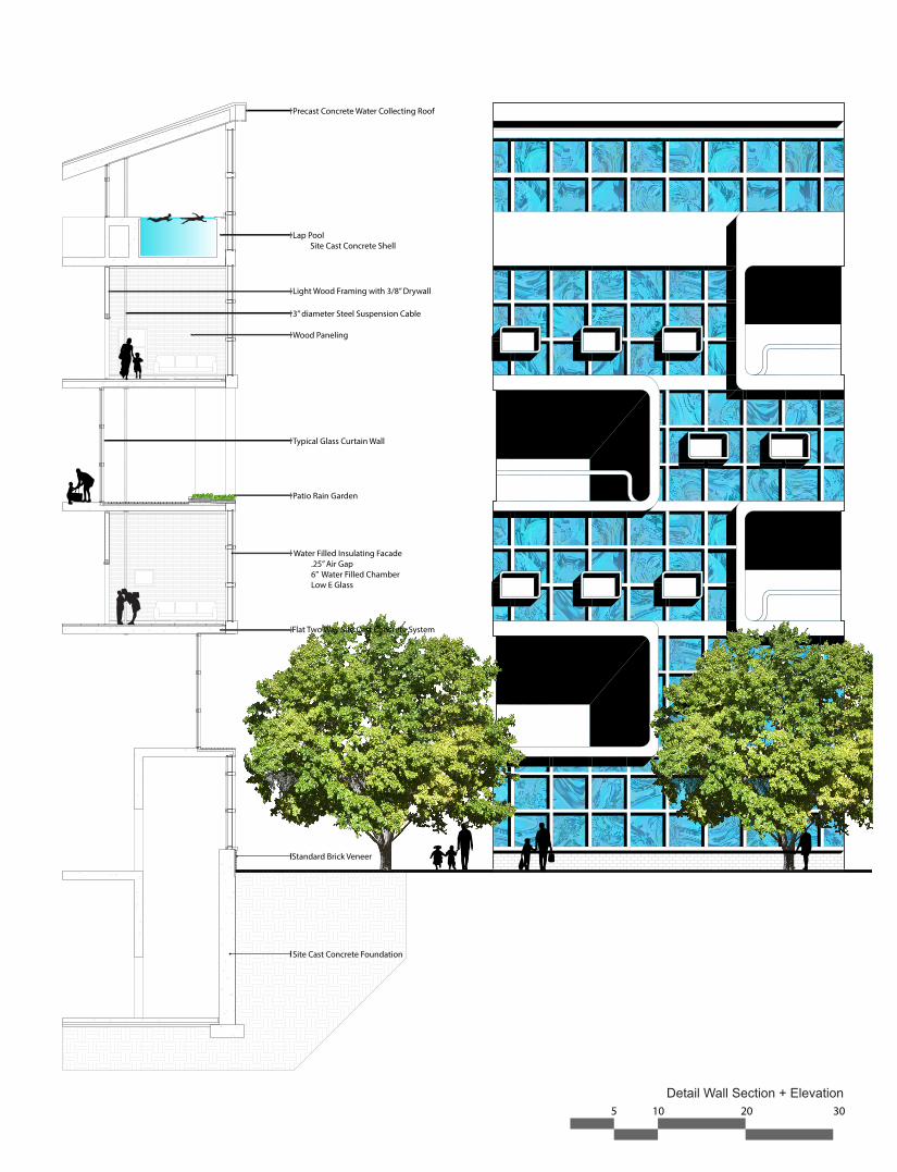
Detail Wall Section + Elevation5 10 20 30
Light Wood Framing with 3/8” Drywall
Water Filled Insulating Facade .25” Air Gap 6” Water Filled Chamber Low E Glass
Lap Pool Site Cast Concrete Shell
3” diameter Steel Suspension Cable
Typical Glass Curtain Wall
Precast Concrete Water Collecting Roof
Site Cast Concrete Foundation
Flat Two Way Site Cast Concrete System
Patio Rain Garden
Standard Brick Veneer
Wood Paneling
Fluid Connections: detail section & elevationChrista TrautmanARC 403: Harry Warren
