a cyborg beetle: insect flight control through an implantable
TRANSCRIPT

A CYBORG BEETLE: INSECT FLIGHT CONTROL THROUGH AN IMPLANTABLE, TETHERLESS MICROSYSTEM
Hirotaka Sato1,2, Christopher W. Berry1, Brendan E. Casey1, Gabriel Lavella1,2, Ying Yao1, John M. VandenBrooks3, Michel M. Maharbiz1,2
1 Department of Electrical Engineering and Computer Science, University of Michigan, Ann Arbor 2 Department of Electrical Engineering and Computer Science, University of California at Berkeley 3 School of Life Sciences, Arizona State University, Tempe ABSTRACT
We present an implantable flight control microsystem for a cyborg beetle (Fig. 1). The system consists of multiple inserted neural and muscular stimulators, a visual stimulator, a polyimide assembly and a microcontroller. The system is powered by two size 5 cochlear microbatteries. The insect platform is Cotinis texana, a 2 cm long, 1 - 2 gram Green June Beetle. We also provide data on the implantation of silicon neural probes, silicon chips, microfluidic tubes, and LED’s introduced during the pupal stage of the beetle. 1. INTRODUCTION
Despite major advances, micro air vehicles (MAV’s) are still limited in size, payload, distance and performance [1]. Various species of insects, among them flies (diptera), moths (lepidoptera), dragonflies (odonata) and beetles (coleoptera) have as-yet unmatched flight performance and increasingly understood muscular and nervous systems [2]. Additionally, some of these insects undergo complete metamorphosis (i.e. form pupae) and are very amenable to implantation and internal manipulation during pupation [3]. Cotinis is particularly suitable for MAV work because it is fast, small, hard-shelled, and an active daylight flyer [4]. Figure 1: (a) illustration of cyborg beetle microsystem. (b) photograph of assembled visual stimulator with LEDs, microcontroller and microbattery, (c) photograph of beetle in flight under microsystem control. For scale, the MSP 430 measures 3 mm x 3mm x 1mm.
2. EXPERIMENTAL RESULTS Stimulator Assembly
The complete microsystem is shown in Fig. 1. The neural stimulation system (Fig. 1a) consists of four neural stimulators of silver thin wire electrodes (Φ75 µm): one implanted dorsally behind eye, in the flight control area of the insect brain and two implanted on either side, anterior to posterior, extending under the flight muscles. A fourth wire inserted into the dorsal thorax is used as a counter electrode. The visual stimulator (Figs. 1b and 1c) consists of white SMT LED’s (Light Emitting Diode, LTST-C171YKT) assembled onto a custom polyimide flexible PCB (Print Circuit Board). The microcontroller drives the LED’s through metal interconnects on the polyimide. Both the neural and visual stimulators are driven by a microcontroller (Texas Instrument, MSP430), and some characterization was conducted by a function generator. Flight command sequences are stored in the 2 KB memory (~1000 flight commands with current program). Michigan neural probes (Fig. 2) with flexible parylene cables were also fabricated and assembled onto polyimide PCB with microbattery. The neural probe fabrication process is shown in Fig. 3 [5,6].
Figure 2: (a) Cross-sectional diagram of Michigan neural probe, (b) complete assembly showing microcontroller, battery and brain stimulator, (c) close-up of stimulation sites.
Parylen cable
cb
Total mass = 422 mg
c
50 µm
a
Parylen cable
cb
Total mass = 422 mg
c
50 µm
a
four-element white LED (1 mg each)
978-1-4244-1793-3/08/$25.00 ©2008 IEEE MEMS 2008, Tucson, AZ, USA, January 13-17, 2008164
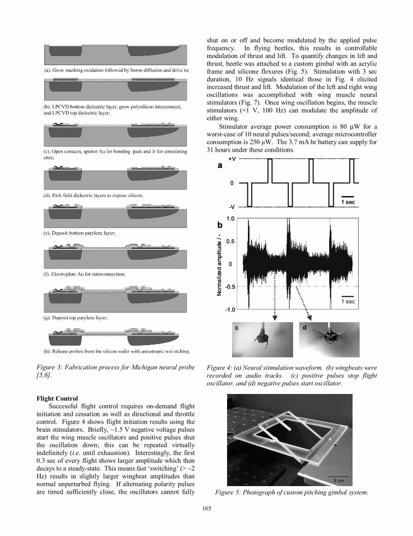
Figure 3: Fabrication process for Michigan neural probe [5,6].
Flight Control
Successful flight control requires on-demand flight initiation and cessation as well as directional and throttle control. Figure 4 shows flight initiation results using the brain stimulators. Briefly, ~1.5 V negative voltage pulses start the wing muscle oscillators and positive pulses shut the oscillation down; this can be repeated virtually indefinitely (i.e. until exhaustion). Interestingly, the first 0.3 sec of every flight shows larger amplitude which then decays to a steady-state. This means fast ‘switching’ (> ~2 Hz) results in slightly larger wingbeat amplitudes than normal unperturbed flying. If alternating polarity pulses are timed sufficiently close, the oscillators cannot fully
shut on or off and become modulated by the applied pulse frequency. In flying beetles, this results in controllable modulation of thrust and lift. To quantify changes in lift and thrust, beetle was attached to a custom gimbal with an acrylic frame and silicone flexures (Fig. 5). Stimulation with 3 sec duration, 10 Hz signals identical those in Fig. 4 elicited increased thrust and lift. Modulation of the left and right wing oscillations was accomplished with wing muscle neural stimulators (Fig. 7). Once wing oscillation begins, the muscle stimulators (+1 V, 100 Hz) can modulate the amplitude of either wing.
Stimulator average power consumption is 80 µW for a worst-case of 10 neural pulses/second; average microcontroller consumption is 250 µW. The 3.7 mA hr battery can supply for 31 hours under these conditions. Figure 4: (a) Neural stimulation waveform. (b) wingbeats were recorded on audio tracks. (c) positive pulses stop flight oscillator, and (d) negative pulses start oscillator.
Figure 5: Photograph of custom pitching gimbal system.
3 cm3 cm
+V
-V
0
1 sec
1 sec
Norm
aliz
ed a
mpl
itude
/ -
0
-0.5
-1.0
1.0
0.5
a
b
c d
+V
-V
0
1 sec
1 sec
Norm
aliz
ed a
mpl
itude
/ -
0
-0.5
-1.0
1.0
0.5
a
b
c d
165

Figure 6: Photographs of gimbal-mounted beetle during un-stimulated (a) and stimulated (b) flight. A light-emitting diode (LED) mounted to the microcontroller acts as an indicator and blinks during stimulation. (c) Gimbal pitch angle during 10 Hz stimulation. Horizontal bars indicate duration of stimulation (3 sec); a 10 Hz bipolar square wave identical to that in Fig. 4a was applied during the indicated periods. Figure 7 Electrical stimulation of wing muscles on either side initiates a turn. Beetles mounted on a long string (10 cm) were programmed with a continuous sequence of left, pause, right, pause instructions; each instruction lasted 2 seconds. (a) leftt flight muscle stimulation generates a right turn, followed by (b) a pause durng which the beetle zigs and zags, followed by (c) right muscle stimulation which generates a left turn. Each photograph consists of 10 frames; frames were taken every 0.2 seconds. Optical Stimulator
Optical stimulation was explored as an alternate method of flight control. Initial characterization was performed by projecting a series of vertical black and white stripes with a DLP onto a paper screen located approximately 15 cm in front of Cotinis texana, which was mounted on the same gimbal as in Fig. 5 (but rotated 90
degrees so as to allow for yaw or roll rotations). During flight, all beetles (N > 15) consistently tracked the stripe motions with their heads, then initiated a turn; delay when switching directions was usually ~2 seconds. This same phenomenon has been demonstrated and characterized in fruit flies [7].
The miniature optical stimulation system is shown in Figs. 1b and 1c. Ten columns of three LED’s are driven by the microcontroller. Each column of LED’s can be illuminated independently to create the illusion of motion. The base of the device is mounted to the pronotum of the beetle and the array of LEDs hangs in front of the beetle's head.
Response to the optical stimulation using the current device varies from beetle to beetle and is susceptible to interference from ambient light. There are beetles which exhibit a strong turning response, but only in the dark. Figure 8 plots turn data for a representative experiment. In this experiment, the beetle and optical stimulation device were mounted in the dark onto a miniature ball bearing, which allows for continuous yaw rotation about the beetle's vertical axis. The device alternatively illuminated LED’s on the left (6 sec), progressed illumination towards the right side (0.5 – 1.5 sec), illuminated the right side (6 sec), then transited back left (0.5 – 1.5 sec); this sequence was repeated indefinitely. In this experiment, the beetle's flight consistently turned away from the side of the illuminated LEDs. Delays of up to 4 seconds were observed between the time that the LEDs changed sides to the time that the beetle began turning away from them. Extensive experiments (N > 20 beetles, M > 10 different LED actuation patterns) were performed with varied visual motion gradients between the sides, frequency of LED changes, and number of LED’s illuminated (i.e. apparent size of bright spot). Except for the stimulus described above, none of the variations yielded responses correlated with stimulus. Complete results are being compiled for publication. Figure 8: Plot of yaw of beetle and LED stimulus. Yaw angle is measured from below the beetle, and the side of the LED stimulus (dotted line) is with respect to the beetle’s point of view. In general, the beetle rotates away from the side of the lit LED. A response time up to 4 seconds is counted before the beetle changes directions.
LEDLEDLED
aa bb cc
0 5 10 150
5
10
15
20
25
30
35
Time (seconds)
Ang
le (
degr
ees)
a b
c
166
Implantation
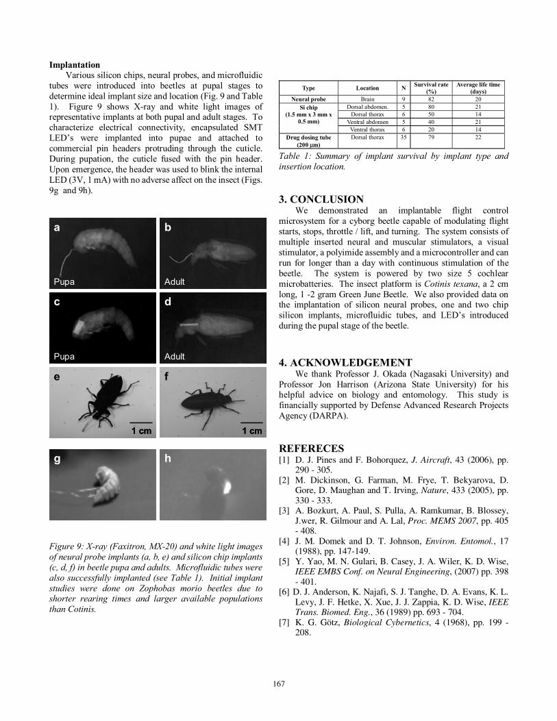
Various silicon chips, neural probes, and microfluidic tubes were introduced into beetles at pupal stages to determine ideal implant size and location (Fig. 9 and Table 1). Figure 9 shows X-ray and white light images of representative implants at both pupal and adult stages. To characterize electrical connectivity, encapsulated SMT LED’s were implanted into pupae and attached to commercial pin headers protruding through the cuticle. During pupation, the cuticle fused with the pin header. Upon emergence, the header was used to blink the internal LED (3V, 1 mA) with no adverse affect on the insect (Figs. 9g and 9h).
Figure 9: X-ray (Faxitron, MX-20) and white light images of neural probe implants (a, b, e) and silicon chip implants (c, d, f) in beetle pupa and adults. Microfluidic tubes were also successfully implanted (see Table 1). Initial implant studies were done on Zophobas morio beetles due to shorter rearing times and larger available populations than Cotinis.
Type Location N Survival rate (%)
Average life time (days)
Neural probe Brain 9 82 20 Dorsal abdomen. 5 80 21
Dorsal thorax 6 50 14 Ventral abdomen 5 40 21
Si chip (1.5 mm x 3 mm x
0.5 mm) Ventral thorax 6 20 14
Drug dosing tube (200 µm)
Dorsal thorax 35 79 22
Table 1: Summary of implant survival by implant type and insertion location. 3. CONCLUSION
We demonstrated an implantable flight control microsystem for a cyborg beetle capable of modulating flight starts, stops, throttle / lift, and turning. The system consists of multiple inserted neural and muscular stimulators, a visual stimulator, a polyimide assembly and a microcontroller and can run for longer than a day with continuous stimulation of the beetle. The system is powered by two size 5 cochlear microbatteries. The insect platform is Cotinis texana, a 2 cm long, 1 -2 gram Green June Beetle. We also provided data on the implantation of silicon neural probes, one and two chip silicon implants, microfluidic tubes, and LED’s introduced during the pupal stage of the beetle. 4. ACKNOWLEDGEMENT We thank Professor J. Okada (Nagasaki University) and Professor Jon Harrison (Arizona State University) for his helpful advice on biology and entomology. This study is financially supported by Defense Advanced Research Projects Agency (DARPA). REFERECES [1] D. J. Pines and F. Bohorquez, J. Aircraft, 43 (2006), pp.
290 - 305. [2] M. Dickinson, G. Farman, M. Frye, T. Bekyarova, D.
Gore, D. Maughan and T. Irving, Nature, 433 (2005), pp. 330 - 333.
[3] A. Bozkurt, A. Paul, S. Pulla, A. Ramkumar, B. Blossey, J.wer, R. Gilmour and A. Lal, Proc. MEMS 2007, pp. 405 - 408.
[4] J. M. Domek and D. T. Johnson, Environ. Entomol., 17 (1988), pp. 147-149.
[5] Y. Yao, M. N. Gulari, B. Casey, J. A. Wiler, K. D. Wise, IEEE EMBS Conf. on Neural Engineering, (2007) pp. 398 - 401.
[6] D. J. Anderson, K. Najafi, S. J. Tanghe, D. A. Evans, K. L. Levy, J. F. Hetke, X. Xue, J. J. Zappia, K. D. Wise, IEEE Trans. Biomed. Eng., 36 (1989) pp. 693 - 704.
[7] K. G. Götz, Biological Cybernetics, 4 (1968), pp. 199 - 208.
g h
a
Pupa
c
Pupa
b
Adult
d
Adult
e
1 cm
f
1 cm
gg hh
a
Pupa
a
Pupa
c
Pupa
c
Pupa
b
Adult
b
Adult
d
Adult
d
Adult
e
1 cm
e
1 cm1 cm
f
1 cm
f
1 cm1 cm
167