a combined solar electric and storable chemical … · a combined solar electric and storable...
TRANSCRIPT
Carolyn R. Mercer and Steven R. OlesonGlenn Research Center, Cleveland, Ohio
Bret G. DrakeJohnson Space Center, Houston, Texas
A Combined Solar Electric and Storable Chemical Propulsion Vehicle for Piloted Mars Missions
NASA/TM—2014-218093
December 2014
AIAA–2013–5492
https://ntrs.nasa.gov/search.jsp?R=20150002749 2018-06-05T20:27:59+00:00Z

Carolyn R. Mercer and Steven R. OlesonGlenn Research Center, Cleveland, Ohio
Bret G. DrakeJohnson Space Center, Houston, Texas
A Combined Solar Electric and Storable Chemical Propulsion Vehicle for Piloted Mars Missions
NASA/TM—2014-218093
December 2014
AIAA–2013–5492

Acknowledgments
Level of Review

NASA/TM—2014-218093 1
A Combined Solar Electric and Storable Chemical Propulsion Vehicle for Piloted Mars Missions
Carolyn R. Mercer and Steven R. Oleson
National Aeronautics and Space Administration Glenn Research Center Cleveland, Ohio 44135
Bret G. Drake
National Aeronautics and Space Administration Johnson Space Center Houston, Texas 77058
Abstract The Mars Design Reference Architecture (DRA) 5.0 explored a piloted Mars mission in the 2030
timeframe, focusing on architecture and technology choices. The DRA 5.0 focused on nuclear thermal and cryogenic chemical propulsion system options for the mission. Follow-on work explored both nuclear and solar electric options. One enticing option that was found in a NASA Collaborative Modeling for Parametric Assessment of Space Systems (COMPASS) design study used a combination of a 1-MW-class solar electric propulsion (SEP) system combined with storable chemical systems derived from the planned Orion crew vehicle. It was found that by using each propulsion system at the appropriate phase of the mission, the entire SEP stage and habitat could be placed into orbit with just two planned Space Launch System (SLS) heavy lift launch vehicles assuming the crew would meet up at the Earth-Moon (E-M) L2 point on a separate heavy-lift launch. These appropriate phases use high-thrust chemical propulsion only in gravity wells when the vehicle is piloted and solar electric propulsion for every other phase. Thus the SEP system performs the spiral of the unmanned vehicle from low Earth orbit (LEO) to E-M L2 where the vehicle meets up with the multi-purpose crew vehicle. From here SEP is used to place the vehicle on a trajectory to Mars. With SEP providing a large portion of the required capture and departure changes in velocity ( ) at Mars, the provided by the chemical propulsion is reduced by a factor of five from what would be needed with chemical propulsion alone at Mars. This trajectory also allows the SEP and habitat vehicle to arrive in the highly elliptic 1-sol parking orbit compatible with envisioned Mars landing concepts. This paper explores mission options using between SEP and chemical propulsion, the design of the SEP system including the solar array and electric propulsion systems, and packaging in the SLS shroud. Design trades of stay time, power level, specific impulse and propellant type are discussed.
1.0 Introduction NASA’S goal for human spaceflight is to expand permanent human presence beyond low Earth orbit
(LEO). To achieve this goal, NASA is identifying potential missions and technologies needed to conduct those missions safely and cost effectively. Mission options include piloted destinations to LEO and the International Space Station (ISS); high Earth orbit and geosynchronous orbit; cislunar space, lunar orbit, and the surface of the Moon; near-Earth objects; and the moons of Mars, Mars orbit, and the surface of Mars. The Mars Design Reference Architecture (DRA) 5.0 explores a piloted mission to Mars in the 2030 timeframe, focusing on architecture and technology choices (Ref. 1). Table 1 shows propulsion options that have been considered to transport crew and cargo to Mars, including all-chemical propulsion, nuclear thermal propulsion (NTP), and nuclear electric propulsion (NEP). This paper describes a transportation architecture using solar electric propulsion (SEP) coupled with small chemical thrusters to transport six crew and needed cargo for a long-stay Mars mission using solar arrays constrained to provide no more

NASA/TM—2014-218093 2
TABLE 1.— MARS LANDING. [Chemical, NTP, and NEP values obtained from 2012 studies by NASA’s Human Spaceflight Architecture Team and are included to show the nominal feasibility of the SEP-Chem system.]
Cargo Missions
Crew Mission
2037 Conjunction Class “long stay” mission
Chemical Propulsion Nuclear Thermal Nuclear Electric Solar/Chem
Electric Propulsion Power level N/A N/A 2.5 MW crew/
1 MW cargo 800 kW Solar
Total Mass (t) ~1250 ~890 ~770 ~780 # Heavy Lift (SLS) Launches ~12 9 (7) ~7 ~7
SLS Delivery to LEO (t) 105 and 130 105 (130) 105 and 130 105 and 130
SLS Shroud Dia./ Barrel Length 10 / 22 10 / 25 10 / 25 10 / 10
Trip Duration (days to Mars, on Mars, back home)
180 / 500 / 200 880 days total trip
174 / 539 / 201 914 days total trip
309 / 400 / 224 980 days total trip
439 / 300 / 326 1065 days total trip
Comments Requires propellant depot
Number of launches reduced to 7 with 130 mt
SLS
1– required to provide consumables to E-M L2
than 1 MW of power. This relatively low mass and robust transportation system can deliver the crew to an elliptical 1-sol orbit similar to chemical or NTP systems, and can substantially reduce the number of launches needed for such a mission when compared to an all-chemical system. This concept is dubbed “SEP-Chem” and its size is shown in Figure 1 relative to the ISS. Its essential feature is the use of SEP to efficiently traverse the long, deep-space portions of the mission and thereby reduce the amount of needed propellant relative to an all-chemical stage, and the use of a small Orion-derived chemical system to provide final capture at and initial departure from Mars, thereby preventing the long spirals needed by an all-SEP stage. The transit trip times will be longer than needed with all-chemical propulsion or NTP, but will allow for a 300-day surface stay with a total trip time of 1050 days, which is only 65 days longer than the targeted 1000 days. It should be noted that this comparison shows that the nominal trip times for the three types of architectures are similar only for the particular mission studied, namely a conjunction class mission with a 2037 launch date. Also, the chemical, NTP and NEP systems shown in Table 1 are included solely to show that the trip times and number of launches needed by the SEP-Chem system are reasonable.

NASA/TM—2014-218093 3
Figure 1.—Size of the piloted combined SEP-chemical vehicle(left)
compared to ISS (right). (Images to scale.)
The design trades used to determine this SEP-Chem concept are described in Section 2.0, including an analysis of an all-SEP system, several SEP-Chem variants, a comparison with an all-chemical system, and an analysis of several propulsion and power variants. Per DRA 5.0, the assumed mission includes the transportation of six crew in a habitation element to and from Mars, and also the delivery of two 100-t cargo vehicles to Mars, each captured using an aeroshell. The difference from the chemical or NTP versions of DRA 5.0 is that the SEP-Chem crew vehicle will spiral from LEO to the Earth-Moon (E-M) L2 point unpiloted, and the crew will rendezvous with it there. SEP-Chem accomplishes the crew portion of this architecture with three heavy lift launch vehicles: two for the SEP-Chem and habitat vehicles which mate in LEO, and one for the crew to the L2 point. All three launches use NASA’s planned Space Launch System (SLS). A separate delivery of about 18 t of crew consumables to the habitat in LEO is
In addition to payload requirements and launch vehicle assumptions, design constraints included a
round-trip piloted mission duration of less than 1000 days to minimize crew exposure to the deep-space environment and a maximum solar array power delivery of 1 MW to permit the use of existing design concepts. Additional design constraints and considerations are given in Section 2.0, as well as a description of the vehicles and trajectories studied, and the key system-level impacts for several propulsion and power technologies. Finally, the conclusions reached regarding relevant SEP technologies for piloted missions to Mars are compared to technologies needed for other exploration destinations such as asteroids and cislunar space. A roadmap for building the stepping stones needed to reach Mars is also presented. Although these results are not definitive because the full breadth of design space was not explored nor were the design impacts of contingency operations, we believe that they are representative and provide insight into the relative benefits of power and propulsion technologies for solar electric vehicles of this class. This work can help guide technology development investments to enable future missions to Mars.
NASA/TM—2014-218093 4
2.0 Design Consistent with DRA 5.0, the design reference mission for this study is a conjunction-class (long-stay)
trajectory for six crew in the mid-2030 timeframe, with pre-deployed cargo. The baseline architecture used in DRA 5.0 included a nuclear thermal rocket with an outbound transit time for the crew of about 180 days in 2037, a surface stay of about 500 days, and a return trip of about 200 days, yielding a total piloted-trip time of about 900 days. The date of 2037 was chosen because it represents a challenging opportunity across the 15-year synodic cycle.1 We therefore set an objective to keep the total crew time to 1000 days or less, including a Mars surface stay of 365 days or more. We further set a goal of requiring only two heavy-lift SLS launches, and solar arrays sized to provide no more than 1 MW of electrical power. In addition to the SEP stage, the system elements include a 24-t multipurpose crew vehicle and a 53-t deep-space habitat (DSH). All design trades reported in this paper begin with the SEP spacecraft spiraling from LEO to E-M L2 for rendezvous with a pre- in a high energy condition—E-M L2 was chosen for this study, though a near-Earth escape would suffice as well. The figures of merit, trajectory trades, and guiding design principles are described in Section 2.1; trajectory analyses are described in Section 2.2; and the baseline vehicle and its variants are described in Section 2.3.
2.1 Design Approach
To conduct the parametric assessment of propulsion and power technologies, the Collaborative Modeling for Parametric Assessment of Space Systems (COMPASS) (Ref. 2) team at the NASA Glenn Research Center started with a clean sheet design using the following figures of merit:
Total crew time of 1000 days or less (final design is 65 days over) Mars stay time of 365 days or more (final design is 300 days) Mass and volume o Initial spacecraft in mass in LEO sufficiently low to require only two SLS launches for the
unpiloted crew vehicle SLS net launch capability of 113.8 t delivery to LEO (–92.5 km by 407 km), with an 8.5- by 25-m shroud (final design also required ~18 t
o No more than 1 MW of electric power to the electric propulsion system at beginning of life
Then the following mission trades were conducted:
All-SEP—SEP provides all change in velocity ( ) from L2 to Mars and back All-Chemical—Chemical propulsion provides all from L2 to Mars and back SEP-Chem—SEP provides interplanetary ical propulsion provides gravity well o Interplanetary transit with and without an Earth gravity assist flyby o SEP technology variants
Specific impulse (Isp): 2000 to 3000 s Power to thrusters: 600 to 900 kW
Thruster type: Hall effect and nested Hall effect Power processor: Direct drive (DDU) and conventional power processing unit (PPU)
o Chemical technology variants Storable and cryogenic systems
1 For Mars, opportunities to depart from Earth occur every 26 months and the total energy required essentially repeats over this 15-year cycle. This repetition of energy is referred to as the synodic cycle.
NASA/TM—2014-218093 5
The spacecraft was designed to be single-fault tolerant in the design of the subsystems, where possible. Exceptions to this include the electric power system, propellant tanks, and radiators that have zero fault tolerance, although they are designed to accommodate some performance degradation. Note that because contingency operations are not included in this analysis, conclusions about the relative merits of parameterized power and propulsion technologies must be treated as preliminary. Mass growth calculations were conducted according to AIAA S–120–2006, “Standard Mass Properties Control for Space Systems.” The percent growth factors specified in this standard were applied to each subsystem before an additional growth was carried at the system level to ensure an overall growth of at least 30 percent on the dry mass of the entire system. Growth in the propellant mass was carried in the propellant calculation. A 30 percent growth factor on the bottoms-up power requirements for the bus subsystems was used, with a 5 percent margin for the electric thruster power requirements.
The Spacecraft N-body Analysis Program (Ref. 3) was used to conduct trajectory analyses. The Mission Analysis Low-Thrust Optimization interplanetary low-thrust trajectory optimization tool (Ref. 4) was used to determine the propellant mass needed to perform the heliocentric phase of the mission. Detailed descriptions of the mission design and trades can be found in Reference 5.
2.2 Trajectory Analysis
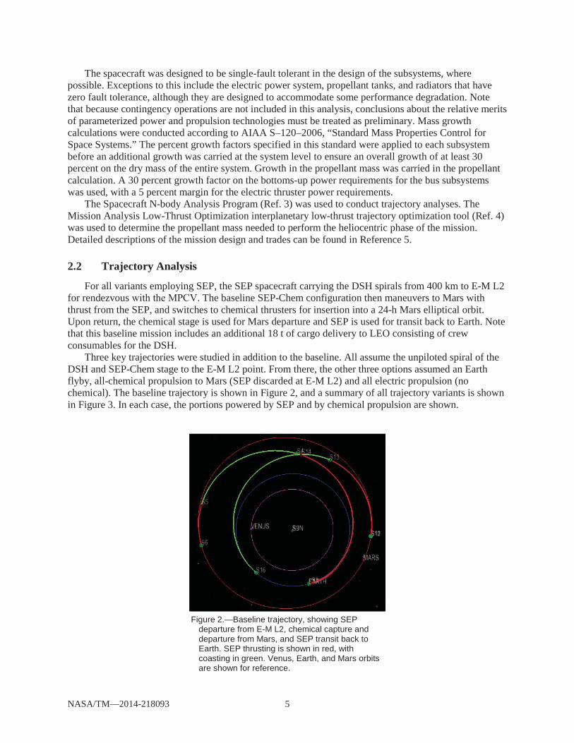
For all variants employing SEP, the SEP spacecraft carrying the DSH spirals from 400 km to E-M L2 for rendezvous . The baseline SEP-Chem configuration then maneuvers to Mars with thrust from the SEP, and switches to chemical thrusters for insertion into a 24-h Mars elliptical orbit. Upon return, the chemical stage is used for Mars departure and SEP is used for transit back to Earth. Note that this baseline mission includes an additional 18 t of cargo delivery to LEO consisting of crew consumables for the DSH.
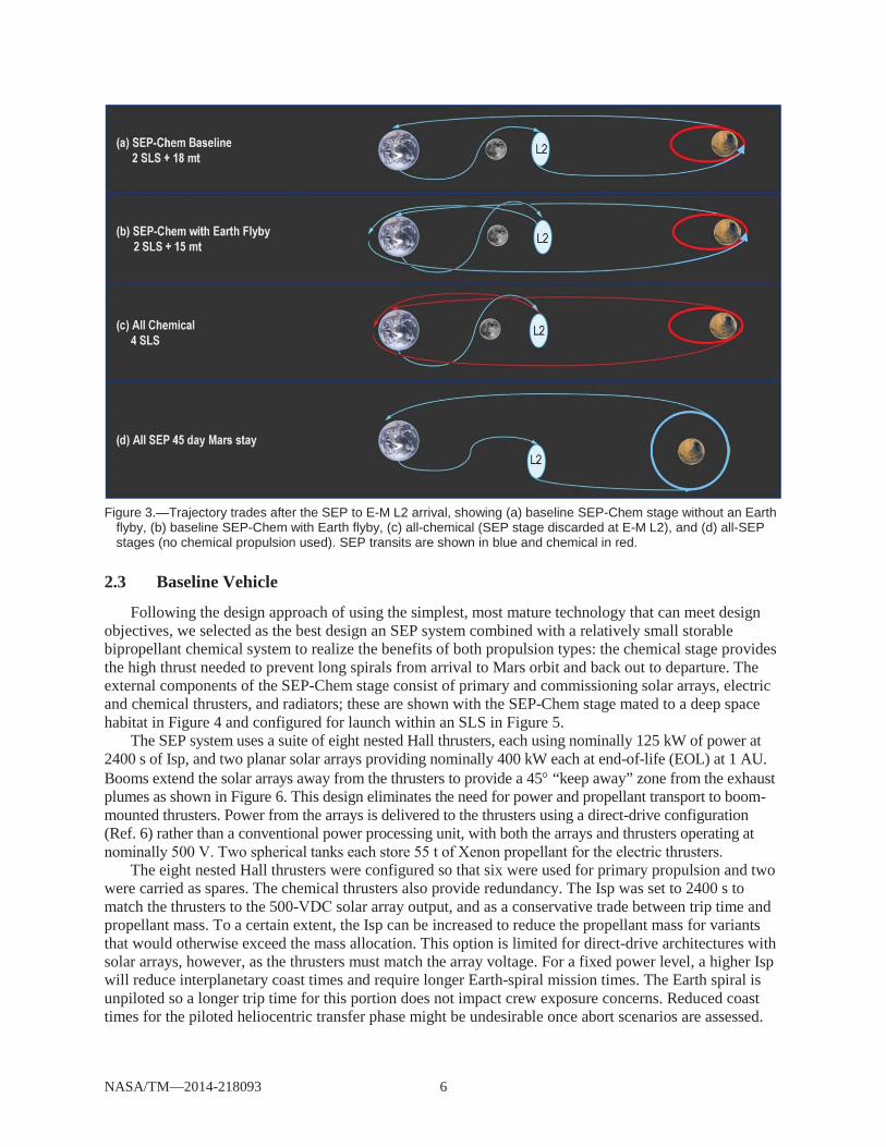
Three key trajectories were studied in addition to the baseline. All assume the unpiloted spiral of the DSH and SEP-Chem stage to the E-M L2 point. From there, the other three options assumed an Earth flyby, all-chemical propulsion to Mars (SEP discarded at E-M L2) and all electric propulsion (no chemical). The baseline trajectory is shown in Figure 2, and a summary of all trajectory variants is shown in Figure 3. In each case, the portions powered by SEP and by chemical propulsion are shown.
Figure 2.—Baseline trajectory, showing SEP
departure from E-M L2, chemical capture and departure from Mars, and SEP transit back to Earth. SEP thrusting is shown in red, with coasting in green. Venus, Earth, and Mars orbits are shown for reference.
NASA/TM—2014-218093 6
Figure 3.—Trajectory trades after the SEP to E-M L2 arrival, showing (a) baseline SEP-Chem stage without an Earth
flyby, (b) baseline SEP-Chem with Earth flyby, (c) all-chemical (SEP stage discarded at E-M L2), and (d) all-SEPstages (no chemical propulsion used). SEP transits are shown in blue and chemical in red.
2.3 Baseline Vehicle
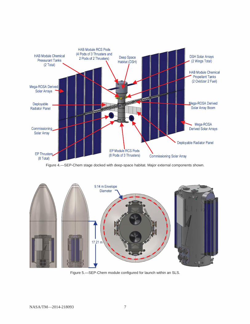
Following the design approach of using the simplest, most mature technology that can meet design objectives, we selected as the best design an SEP system combined with a relatively small storable bipropellant chemical system to realize the benefits of both propulsion types: the chemical stage provides the high thrust needed to prevent long spirals from arrival to Mars orbit and back out to departure. The external components of the SEP-Chem stage consist of primary and commissioning solar arrays, electric and chemical thrusters, and radiators; these are shown with the SEP-Chem stage mated to a deep space habitat in Figure 4 and configured for launch within an SLS in Figure 5.
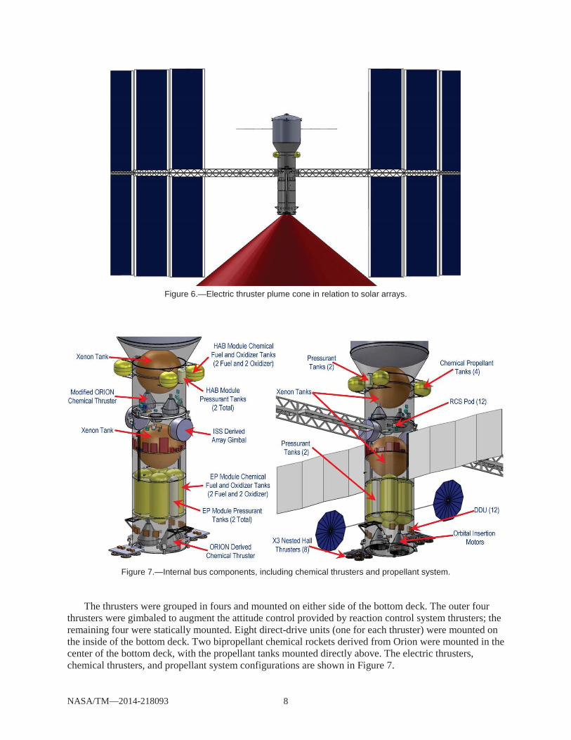
The SEP system uses a suite of eight nested Hall thrusters, each using nominally 125 kW of power at 2400 s of Isp, and two planar solar arrays providing nominally 400 kW each at end-of-life (EOL) at 1 AU. Booms extend the solar arrays away from the thrusters to provide a 45 “keep away” zone from the exhaust plumes as shown in Figure 6. This design eliminates the need for power and propellant transport to boom-mounted thrusters. Power from the arrays is delivered to the thrusters using a direct-drive configuration (Ref. 6) rather than a conventional power processing unit, with both the arrays and thrusters operating at
The eight nested Hall thrusters were configured so that six were used for primary propulsion and two
were carried as spares. The chemical thrusters also provide redundancy. The Isp was set to 2400 s to match the thrusters to the 500- solar array output, and as a conservative trade between trip time and propellant mass. To a certain extent, the Isp can be increased to reduce the propellant mass for variants that would otherwise exceed the mass allocation. This option is limited for direct-drive architectures with solar arrays, however, as the thrusters must match the array voltage. For a fixed power level, a higher Isp will reduce interplanetary coast times and require longer Earth-spiral mission times. The Earth spiral is unpiloted so a longer trip time for this portion does not impact crew exposure concerns. Reduced coast times for the piloted heliocentric transfer phase might be undesirable once abort scenarios are assessed.
NASA/TM—2014-218093 7
Figure 4.—SEP-Chem stage docked with deep-space habitat. Major external components shown.
Figure 5.—SEP-Chem module configured for launch within an SLS.
NASA/TM—2014-218093 8
Figure 6.—Electric thruster plume cone in relation to solar arrays.
Figure 7.—Internal bus components, including chemical thrusters and propellant system.
The thrusters were grouped in fours and mounted on either side of the bottom deck. The outer four thrusters were gimbaled to augment the attitude control provided by reaction control system thrusters; the remaining four were statically mounted. Eight direct-drive units (one for each thruster) were mounted on the inside of the bottom deck. Two bipropellant chemical rockets derived from Orion were mounted in the center of the bottom deck, with the propellant tanks mounted directly above. The electric thrusters, chemical thrusters, and propellant system configurations are shown in Figure 7.

NASA/TM—2014-218093 9
igh thruster efficiency, and it is more easily stored than other heavy noble gases. Two 3.9-m-diameter spherical composite overwrap pressure vessel tanks stored the xenon as a supercritical gas at 1200 psia. Note that because of packaging constraints, one of the xenon tanks is launched with the DSH.
Inverted metamorphic multijunction (IMM) solar cells with a beginning-of-life (BOL) efficiency at 1 AU of 33 percent were chosen as the baseline. the Hall thruster plumes is expected to degrade the solar arrays; we used 6-mil coverglasses and assumed a total 31 percent degradation at EOL. No damage was assumed to occur in heliocentric space. As the solar array voltage degrades, the current is adjusted, altering the thruster mass flow rate to maintain a fixed Isp. Arrays were sized such that each of the two wings have an area of 2383 m2 to provide 1 MW at BOL and 800 kW at EOL. Two 12-m2 deployment of the main arrays. Avionics assume 100 kRad survivability.
Two 120-
eclipse. “No-roll” steering was chosen to eliminate the considerable mass of control moment gyroscopes and
as a result, we accepted secondary-axis Sun pointing errors and the attendant power loss. Since only one revolute axis is available for tracking, the arrays are revolved to minimize the Sun off-pointing angle while under thrust. Array tracking is controlled with ISS-derived solar alpha rotary joint gimbals, with mass reduced by removing the ISS in-flight servicing requirement. The assumed launch date was favorable for the use of no-roll steering because the maximum angle between the arrays and Sun occurs early in the spiral trajectory, when the BOL power is still available. This beta angle may occur later in the trajectory for different launch dates, requiring either oversized arrays or longer trip times because of the reduced power. Four RCS thruster pods provide roll, pitch, and yaw control, augmented by four gimbaled Hall thrusters.
Radiators located directly below the solar array gimbals are pointed perpendicular to the arrays to point away from the Sun to provide the best view for thermal rejection. All components of the thermal system were sized for the worst-case environmental conditions (LEO), with no redundancy. Micrometeoroid and orbital debris shielding was used to protect critical systems such as the propellant tanks and exposed heat pipes. Shielding by the aluminum structure is expected to be sufficient to protect electronics from radiation. The composite thrust tube design was sized to carry the mass of the DSH and space exploration vehicle during launch. All communications are assumed to be performed by the DSH, including relaying housekeeping commands and data for the SEP module.
The mass of the major system elements are shown in Table 2. The mass of the DSH was provided by the Human Space Flight Architecture Team (Ref. 7).
Two cargo vehicles that precede the piloted SEP-Chem stage by one opportunity were each assumed to deliver 103-t aeroshells, one carrying a Mars lander and the other carrying the Mars landed habitat. The trajectories of both cargo missions use an all-SEP system, with the chemical propulsion system replaced
Without the chemical stage to reduce the Mars capture, the SEP cargo vehicle flies by Mars, and the cargo uses its aeroshell for aerocapture to deliver itself into Mars orbit.

NASA/TM—2014-218093 10
TABLE 2.—MASS DISTRIBUTION OF BASELINE SEP- INCLUDING THE DSH.
3.0 Parametric Assessments of Power and Propulsion Four propulsion variants were studied to determine their effect on the SEP-Chem vehicle mass and
cost relative to the baseline: smaller nested Hall thrusters at a lower Isp, smaller single-channel Hall thrusters, nested Hall thrusters using a dual Isp and a conventional power processing unit, and cryogenic chemical propellant storage.
solar array structures (roll out and fold out), and two types of array configurations (planar and concentrators) were considered, but detailed mass analyses were not done for these variants.
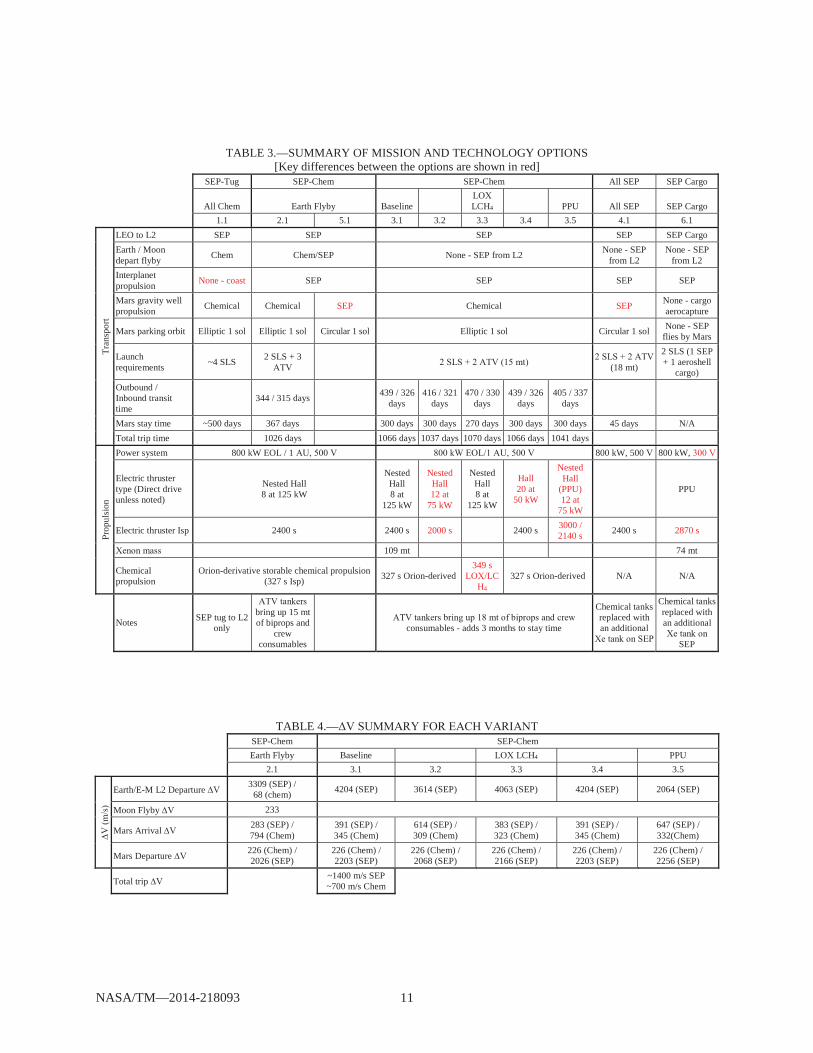
The effect of each propulsion variant on trip time is provided in Table 3, Table 4 shows the each portion of the trip for each variant, and the dry, wet, and inert masses for each are shown in Table 5. A description of each variant is provided in the following two sections.
NASA/TM—2014-218093 11
TABLE 3.—SUMMARY OF MISSION AND TECHNOLOGY OPTIONS [Key differences between the options are shown in red]
SEP-Tug SEP-Chem SEP-Chem All SEP SEP Cargo
All Chem Earth Flyby Baseline
LCH4 PPU All SEP SEP Cargo 1.1 2.1 5.1 3.1 3.2 3.3 3.4 3.5 4.1 6.1
Tran
spor
t
LEO to L2 SEP SEP SEP SEP SEP Cargo Earth / Moon depart flyby Chem Chem/SEP None - SEP from L2 None - SEP
from L2 None - SEP
from L2 Interplanet propulsion None - coast SEP SEP SEP SEP
Mars gravity well propulsion Chemical Chemical SEP Chemical SEP None - cargo
aerocapture
Mars parking orbit Elliptic 1 sol Elliptic 1 sol Circular 1 sol Elliptic 1 sol Circular 1 sol None - SEP flies by Mars
Launch requirements ~4 SLS 2 SLS + 3
(18 mt)
2 SLS (1 SEP + 1 aeroshell
cargo) Outbound / Inbound transit time
344 / 315 days 439 / 326 days
416 / 321 days
470 / 330 days
439 / 326 days
405 / 337 days
Mars stay time ~500 days 367 days 300 days 300 days 270 days 300 days 300 days 45 days N/A Total trip time 1026 days 1066 days 1037 days 1070 days 1066 days 1041 days
Prop
ulsi
on
Power system 800 kW EOL / 1 800 kW, 500 800 kW,
Electric thruster type (Direct drive unless noted)
Nested Hall 8 at 125 kW
Nested Hall 8 at
125 kW
Nested Hall 12 at
75 kW
Nested Hall 8 at
125 kW
Hall 20 at
50 kW
Nested Hall
(PPU) 12 at
75 kW
PPU
Electric thruster Isp 2400 s 2400 s 2000 s 2400 s 3000 / 2140 s 2400 s 2870 s
109 mt 74 mt
Chemical propulsion
Orion-derivative storable chemical propulsion (327 s Isp) 327 s Orion-derived
349 s /LC
H4 327 s Orion-derived N/A N/A
Notes SEP tug to L2 only
bring up 15 mt of biprops and
crew consumables
consumables - adds 3 months to stay time
Chemical tanks replaced with an additional
Chemical tanks replaced with an additional
SEP
TABLE 4.— SEP-Chem SEP-Chem
Earth Flyby Baseline LCH4 PPU 2.1 3.1 3.2 3.3 3.4 3.5
Earth/E-M L2 Departure 3309 (SEP) / 68 (chem) 4204 (SEP) 3614 (SEP) 4063 (SEP) 4204 (SEP) 2064 (SEP)
Moon Flyby 233
Mars Arrival 283 (SEP) / 794 (Chem)
391 (SEP) / 345 (Chem)
614 (SEP) / 309 (Chem)
383 (SEP) / 323 (Chem)
391 (SEP) / 345 (Chem)
647 (SEP) / 332(Chem)
Mars Departure 226 (Chem) / 2026 (SEP)
226 (Chem) / 2203 (SEP)
226 (Chem) / 2068 (SEP)
226 (Chem) / 2166 (SEP)
226 (Chem) / 2203 (SEP)
226 (Chem) / 2256 (SEP)
Total trip
~1400 m/s SEP ~700 m/s Chem

NASA/TM—2014-218093 12
TABLE 5.—MASS SUMMARY FOR EAC SEP-Chem SEP Cargo
Baseline LCH4 PPU SEP Cargo 3.1 3.2 3.3 3.4 3.5 6.1
SEP SEP Cargo SEP Piloted SLS Launch 1 - HAB Module Totals SEP Piloted SLS Launch 1 - HAB Module Wet Mass 128 161 131 128 125 111 SEP Piloted SLS Launch 1 - HAB Module Dry Mass 47 48 50 47 48 105 SEP Piloted SLS Launch 1 - HAB Module Inert Mass 65 68 68 65 66 106 SEP Piloted SLS Launch 2 - SEP Module Totals SEP Piloted SLS Launch 2 - SEP Module Wet Mass 114 114 114 114 114 114 SEP Piloted SLS Launch 2 - SEP Module Dry Mass 28 30 30 28 33 32 SEP Piloted SLS Launch 2 - SEP Module Inert Mass 33 36 36 33 39 36
242 275 245 242 239 225 75 79 81 75 81 137 98 103 104 98 104 142
3.1 Propulsion Trades
At megawatt vehicle power levels, individual Hall thruster power levels of 50 to 100 kW provide a balance between integrated system complexity, fault tolerance, and mass and cost (Ref. 8). One variant was run using twenty 50-kW Hall thrusters at 2400 s and while this system is feasible, packaging this many individual thrusters was challenging. Nested Hall thrusters reduce integration and complexity and provide more continuous thrusting.
Because of the reduction in thruster footprint and specific mass, 125-kW nested-channel Hall thrusters traded well compared to single-channel monolithic Hall thrusters (Ref. 9). The nested Hall
nested Hall thruster, predicted performance of the AFRL/UofM -80 nested-Hall thruster, and high-power single-channel Hall thruster data from the NASA 300M and 457Mv2 thrusters (Refs. 9 to 11). The single-channel 50-kW Hall thruster data used for this study was based on measured NASA 457Mv2 thruster performance (Ref. 11). Magnetic shielding is required to meet the thruster lifetime requirements for this mission (Ref. 12).
Hall thrusters are designed for a given current density of the channel. As the operating voltage is -80 nested Hall thruster
operates at nominally 250 A when all channels are operating, and it can be operated at 175 kW a(3000 s Isp Isp Isp). Similarly, the NASA 457Mv2 single-channel Hall thruster is nominally a 100-(3000 s Isp Isp Isp). For direct drive power processing, thruster Isp for the mission is fixed based upon the fixed solar array voltage. When using a power processing unit, variable Isp operation allows greater mission flexibility to optimize the electric propulsion system performance for different mission segments (e.g. 3000 s Earth spiral, 2000 s interplanetary) at the expense of mass and efficiency. Alternate propellants (e.g., Krypton) and thruster technologies (e.g., magnetoplasmadynamic) were considered but not selected because of storability/efficiency and maturity considerations, respectively.
One variant was run with a conventional PPU using twelve 75-kW nested Hall thrusters. This required a dual set point for the Isp: 3000 s during the unpiloted spiral to L2, and either 2140 or 3000 s for the piloted LEO to L2 spiral. The increased Isp increased this spiral trip time from 480 to 630 days. The use of PPUs instead of DDUs increases the system mass primarily because isolation transformers must be added to regulate the voltage generated by the solar arrays to match that needed by the thrusters, and bigger radiators are needed to reject the additional heat generated by the less efficient PPUs (~95 percent efficient PPU versus 99 percent efficient DDU). PPU mass was assumed to be 100 kg each, although they

NASA/TM—2014-218093 13
may be as low as 88 kg. Note that while the DDUs reduce system mass, they potentially increase operational risk because of their inability to operate over wide voltage swings.
For the chemical thruster, Orion-derived storable systems provide better performance for the low -Chem mission requirements when compared to cryogenic systems such as
/LCH4 (liquid methane) due to lighter/denser storage systems. Table 3 shows that the use of 4 reduces the Mars stay time by 30 days even as the total piloted trip time is slightly increased.
3.2 Power System Trades
The roll-out Mega-ROSA (Ref. 13) solar array design was used for all mass and packaging studies, and was found to notionally provide the required stowed dimensions to fit within the SLS fairing and to provide the needed strength and stiffness for deployed operation. The Mega-ROSA design chosen for the baseline used 10 winglets per wing. Each winglet’s dimension is 8.7 m wide by 27.3 m long for a total wing area of 2383 m2. The fold-out MegaFlex (Ref. 14) design was not included in the detailed studies because of time constraints, but it was determined that the circular MegaFlex arrays could be configured with two 30-m-diameter winglets on each side of the spacecraft to provide the needed power and allow for testing in existing ground-test facilities. Deployment booms would be needed to keep the circular arrays outside the cone of the electric thruster plume. In addition to the primary solar arrays, commissioning solar arrays were used for startup power and were derived from an Orion-based UltraFlex design. NASA relies on vendor-provided data to add realism to these concept designs and does not endorse any particular approach.
A 300- s voltage coupled with a high-power Hall thruster using a PPU has a larger inert mass than a 500- m coupled directly to a 2400-s Hall thruster, but provides equivalent performance and more flexibility because it permits the Isp to be varied depending on mission phase or abort needs. The higher mass did not exceed mission requirements, so either a 300- or 500-
IMM solar cells were baselined for these very large solar arrays because it is assumed that at launch time these will be the state of the art in space solar cells and therefore the most economical. Higher efficiency cells would of course be beneficial, but are not required. Using terrestrial cells with much lower efficiencies but lower unit costs per cell would not be prudent because of the need to oversize the arrays to accommodate both the lower power and the large expected radiation losses.
-up” flexible reflectors was designed to reduce the total area of photovoltaic cells. The areal size of the array must increase slightly (~10 percent) to account for the higher operating temperature of the concentrator cells while collecting sufficient solar flux. The concentrators lower the mass of the power system by about 6 percent, and they can potentially lower the cost of arrays by replacing high-cost solar cells with lower cost reflective elements. It is difficult to assess this cost savings because the concentrators will add complexity that will have some associated costs. The pointing requirements needed to maintain full illumination were sufficiently lax to maintain the ability for no-roll steering, so no other changes to the baseline configuration were required.
4.0 Results Through this analysis it has been determined that power limited (<1 MW) SEP systems can perform
piloted Mars missions especially when a relatively small storable bipropellant system is integrated. The addition of a small chemical stage into the architecture not only reduces the time to capture into Mars orbit, thus providing more useful exploration time, but this strategy can place the SEP crew vehicle into an elliptical orbit at Mars, which can significantly reduce the propulsive burden on the Mars lander and ascent vehicles. This SEP-Chem system can deliver the crew vehicle to an elliptical 1-sol orbit similar to chemical or NTP systems, without requiring staging. With 800 kW at EOL, the SEP-Chem can provide 300-day Mars surface stay times for nominally 1050-day missions. The transit trip times (outbound ~400 days, inbound ~300 days) are longer than all-chemical or nuclear thermal rocket systems, but not substantially so. Although the trip duration is a little longer, and the surface stay a little shorter for the
NASA/TM—2014-218093 14
SEP concept, the total deep-space crew exposure may be acceptable as additional research on human performance are conducted on the ISS and other intermediate missions beyond LEO prior to the first human Mars mission. The SEP-Chem vehicle requires an unpiloted transit of >400 days to spiral from LEO to E-M L2 to meet the crew, but this will not affect the total deep-space hazard exposure experienced by the crew.
Given the SLS delivery capabilities assumed for this analysis, it was found that the SLS payloads are about 6 t short for the current SEP-Chem concept and some consumables or storable propellant (~18 t) will need to be delivered using vehicles similar to the A . However, the planned SLS shroud (17 m cylindrical height) is larger than needed for the SEP-Chem concept payloads: if the shroud is shortened to 10 to 12 m, the increased payload capability could accommodate the additional -like launch. Either way, the number of SLS launches is substantially fewer than needed for all-chemical, or even NTP, systems.
Finally, SEP-Chem may have better reliability and abort capabilities because it has two propulsion systems and ample power.
The technologies able to most significantly reduce mass are a flexible blanket solar array, high-voltage power bus, nested Hall thrusters with dual Isp, and large xenon tanks. Each of these requires technology development to bring to flight readiness. A 300- solar array coupled with a high-power Hall thruster using a PPU, while heavier inertly, provides equivalent performance and more flexibility (due to variable Isp depending on mission phase or abort needs) than a 500-coupled with a direct-drive 2400-s Hall thruster.
There are limits to the results of these studies. If a different mission is selected, or if additional abort constraints are included, or if a different suite of technologies is considered, the results will change. However, we believe that these results are reasonable and provide insight into the relative benefits of key power and propulsion technologies for solar electric vehicles of this class of mission.
Solar electric propulsion technologies currently being developed by NASA’s Game Changing Technology Development program are laying the foundation needed for SEP vehicles of this class. In particular, the MegaFlex and Mega-ROSA solar array concepts have a credible chance of scaling up to the nominally 1-MW BOL sizes needed for this mission, with ample room for stowage within the SLS launch vehicle. 20-kW-class wings are being built and tested at the time of this writing, and a nominally 50-kW-sized flight demonstration coupled with analysis and ground deployment tests of very large wings would do much to reduce the technical risk for much larger systems. A previous study (Ref. 15) showed the capabilities of a 300-kW SEP system to transport crew to a near-Earth asteroid requiring 150 kW per wing. A progression of 30-kW, then 150-kW, then 500-kW wings is a reasonable technical progression. Similarly, 125-kW nested Hall thrusters for Mars are a reasonable extension of current laboratory work on 100-kW-class nested Hall thrusters (Ref. 10). Although there are technical risks associated with vehicles this large, the system builds upon technologies that are currently at a high state of development and is well within the realm of feasibility and practicality.
5.0 Conclusion ehicle concepts were assessed to determine the applicability of using SEP technology for piloted
Mars missions as well as to understand the key technology needs. These analyses have shown that power-limited SEP vehicle concepts are viable for human exploration of Mars, especially when high-thrust chemical systems are included as part of the vehicle architecture. The addition of chemical systems can be used to increase the exploration time at Mars as well as place the SEP vehicle into a more favorable elliptical parking orbit. Power required for this vehicle concept was limited to less than 1 MW of total power, adding further to the viability of the concept. These SEP concepts require fewer heavy lift launches compared to other transportation technologies being considered. They also package well into the launch vehicle shrouds and can serve as the transportation vehicle for both crew and unpiloted cargo delivery to Mars. Although reference concepts and implementations have been provided in this paper, many design trades on specific technology implementations and mission modes remain.
NASA/TM—2014-218093 15
References 1. NASA, “Human Exploration of Mars Design Reference Architecture 5.0”, NASA-SP-2009-566,
July 2009. 2. Collaborative Modeling for Parametric Assessment of Space Systems
http://www.grc.nasa.gov/WWW/compass/ [cited 19 Aug 2013]. 3. “Rapid Calculation of Spacecraft Trajectories Using Efficient Taylor Series Integration,” NASA
Tech Briefs, Jan. 1, 2011 http://www.techbriefs.com/component/content/article/9031 [cited 19 Aug 2013].
4. The In-Space Propulsion Technology Project Low-Thrust Trajectory Tool Suite: MALTO http://ntrs.nasa.gov/archive/nasa/casi.ntrs.nasa.gov/20080047350_2008047178.pdf [cited 19 Aug 2013].
5. Burke, L.M, Martini, M.C., and Oleson, S.R. “A High Power Solar Electric Propulsion–Chemical Mission for Human Exploration of Mars,” to be published as a NASA Technical Report in 2013.
6. Hoffman, D. et al., Exploration,” Presented at the 62nd International Astronautical Congress, Cape Town, South Africa, Oct 3-7, 2011, IAC-11-D2.3.5.
7. NASA, “HAT Cycle C: Mars Transit Habitat and Mars Surface Habitat Modeling”, Internal document, August 18, 2011.
8. Hofer, R.R, and Randolph, T.M., “Mass and Cost Model for Selecting Thruster Size in Electric Propulsion Systems,”
9. Brown, D.L., Beal, B.E., and Haas, J.M., “Air Force Research Laboratory High Power Electric Propulsion Technology Development,” 2010 IEEE Aerospace Conference, Big Sky, MT, March 6-13, 2010.
10. Florenz, R., Gallimore, A.D., and Peterson, P.Y., “Developmental Status of a 100-kW Class Laboratory Nested Channel Hall Thruster,” 32nd International Electric Propulsion Conference, Wiesbaden, Germany, September 11 – 15, 2011..
11. Soulas, G.C, Haag, T.W., Herman, D.A., Huang, W., Kamhawi, H., and Shastry, R., “Performance Test Results of the NASA-457M v2 Hall Thruster,” 48th AIAA/ASME/SAE/ASEE Joint Propulsion Conference, Atlanta, GA, July 30 – August 1, 2012.
12. Mikelides, I.G., Katz, I., Hofer, R.R., and Goebel, D.M., “Magnetic Shielding of Walls from the .
13. White, S. et al., “Mega-ROSA Solar Array – Highly Modular Game-Changing Solar Array Technology for NASA SEP and DoD Ultra-High Power Missions,” Presented at the 31st Annual Space Power Workshop, Manhattan Beach, CA, April 22-25, 2013.
14. Eskenazi, M., Murphy, D., McEachen, M., and Spink, J. “MegaFlex – Near Term High Power for Solar Electric Propulsion,” Presented at the 31st Annual Space Power Workshop, Manhattan Beach, CA, April 22-25, 2013.
15. Brophy, J.R., Gershman, R., Strange, N., Landau, D., Merricll, R., and Kerslake, T., “300-kW Solar Electric Propulsion System Configuration for Human Exploration of Near-Earth Asteroids,” AIAA/ASME/SAE/ASEE Joint Propulsion Conference, San Diego, CA, July 31 – August 3, 2011.
REPORT DOCUMENTATION PAGE Form ApprovedOMB No. 0704-0188
The public reporting burden for this collection of information is estimated to average 1 hour per response, including the time for reviewing instructions, searching existing data sources, gathering andmaintaining the data needed, and completing and reviewing the collection of information. Send comments regarding this burden estimate or any other aspect of this collection of information, includingsuggestions for reducing this burden, to Department of Defense, Washington Headquarters Services, Directorate for Information Operations and Reports (0704-0188), 1215 Jefferson Davis Highway, Suite1204, Arlington, VA 22202-4302. Respondents should be aware that notwithstanding any other provision of law, no person shall be subject to any penalty for failing to comply with a collection of information if itdoes not display a currently valid OMB control number.PLEASE DO NOT RETURN YOUR FORM TO THE ABOVE ADDRESS.
1. REPORT DATE (DD-MM-YYYY)01-12-2014
2. REPORT TYPETechnical Memorandum
3. DATES COVERED (From - To)
4. TITLE AND SUBTITLEA Combined Solar Electric and Storable Chemical Propulsion Vehicle for Piloted MarsMissions
5a. CONTRACT NUMBER
5b. GRANT NUMBER
5c. PROGRAM ELEMENT NUMBER
6. AUTHOR(S)Mercer, Carolyn, R.; Oleson, Steven, R.; Drake, Bret, G.
5d. PROJECT NUMBER
5e. TASK NUMBER
5f. WORK UNIT NUMBERWBS 272725.04.01.01.03
7. PERFORMING ORGANIZATION NAME(S) AND ADDRESS(ES)National Aeronautics and Space AdministrationJohn H. Glenn Research Center at Lewis FieldCleveland, Ohio 44135-3191
8. PERFORMING ORGANIZATION REPORT NUMBERE-18772-1
9. SPONSORING/MONITORING AGENCY NAME(S) AND ADDRESS(ES)National Aeronautics and Space AdministrationWashington, DC 20546-0001
10. SPONSORING/MONITOR'S ACRONYM(S)NASA11. SPONSORING/MONITORING REPORT NUMBERNASA/TM-2014-218093
12. DISTRIBUTION/AVAILABILITY STATEMENTUnclassified-UnlimitedSubject Categories: 18 and 20Available electronically at http://www.sti.nasa.govThis publication is available from the NASA Center for AeroSpace Information, 443-757-5802
13. SUPPLEMENTARY NOTES
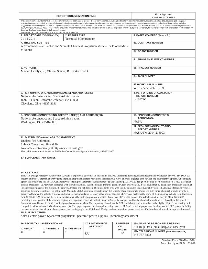
14. ABSTRACTThe Mars Design Reference Architecture (DRA) 5.0 explored a piloted Mars mission in the 2030 timeframe, focusing on architecture and technology choices. The DRA 5.0focused on nuclear thermal and cryogenic chemical propulsion system options for the mission. Follow-on work explored both nuclear and solar electric options. One enticingoption that was found in a NASA Collaborative Modeling for Parametric Assessment of Space Systems (COMPASS) design study used a combination of a 1-MW-class solarelectric propulsion (SEP) system combined with storable chemical systems derived from the planned Orion crew vehicle. It was found that by using each propulsion system atthe appropriate phase of the mission, the entire SEP stage and habitat could be placed into orbit with just two planned Space Launch System (SLS) heavy lift launch vehiclesassuming the crew would meet up at the Earth-Moon (E-M) L2 point on a separate heavy-lift launch. These appropriate phases use high-thrust chemical propulsion only ingravity wells when the vehicle is piloted and solar electric propulsion for every other phase. Thus the SEP system performs the spiral of the unmanned vehicle from low Earthorbit (LEO) to E-M L2 where the vehicle meets up with the multi-purpose crew vehicle. From here SEP is used to place the vehicle on a trajectory to Mars. With SEPproviding a large portion of the required capture and departure changes in velocity ( V) at Mars, the V provided by the chemical propulsion is reduced by a factor of fivefrom what would be needed with chemical propulsion alone at Mars. This trajectory also allows the SEP and habitat vehicle to arrive in the highly elliptic 1-sol parking orbitcompatible with envisioned Mars landing concepts. This paper explores mission options using between SEP and chemical propulsion, the design of the SEP system includingthe solar array and electric propulsion systems, and packaging in the SLS shroud. Design trades of stay time, power level, specific impulse and propellant type are discussed.15. SUBJECT TERMSSolar electric power; Spacecraft propulsion; Spacecraft power supplies; Technology assessment
16. SECURITY CLASSIFICATION OF: 17. LIMITATION OF ABSTRACT
UU
18. NUMBER OF PAGES
22
19a. NAME OF RESPONSIBLE PERSONSTI Help Desk (email:[email protected])a. REPORT
Ub. ABSTRACTU
c. THIS PAGEU 19b. TELEPHONE NUMBER (include area code)
443-757-5802
Standard Form 298 (Rev. 8-98)Prescribed by ANSI Std. Z39-18

