9a- geometric dimensioning &...
TRANSCRIPT
Geometric dimensioning & Geometric dimensioning & tolerancingtolerancing (Part 1)(Part 1)
KCEC 1101
IntroductionIntroduction• Before an object can be built, complete
information about both the size and shape of the object must be available.
• The exact shape of an object is communicated through orthographic drawings, which are developed following standard drawing practices.
• The process of adding size information to a drawing is known as dimensioning the drawing.
• In order that size information is communicated as clearly as possible, standard dimension practices have been established.
DIMENSIONINGDIMENSIONING
• Geometrics is the science of specifying and tolerancing the shapes and locations of features on objects.
• Once the shape of a part is defined with an orthographic drawings, the size information is added also in the form of dimensions.
• Dimensioning a drawing also identifies the tolerance (or accuracy) required for each dimension.
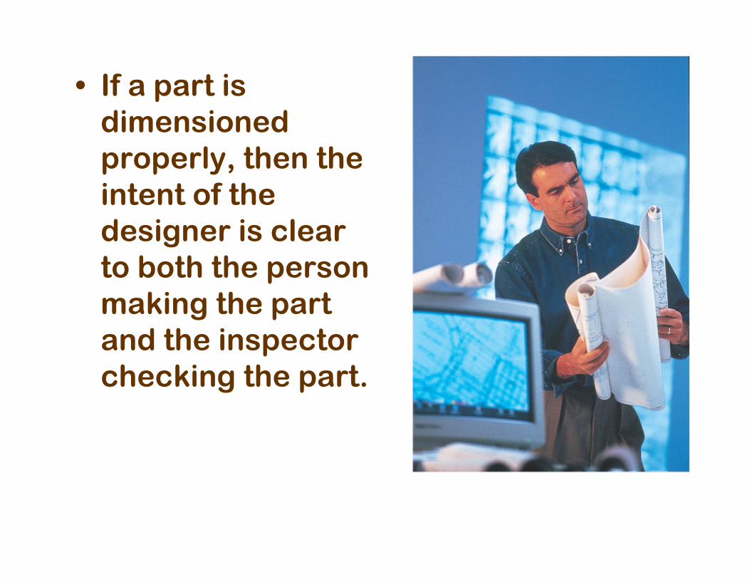
• If a part is dimensioned properly, then the intent of the designer is clear to both the person making the part and the inspector checking the part.
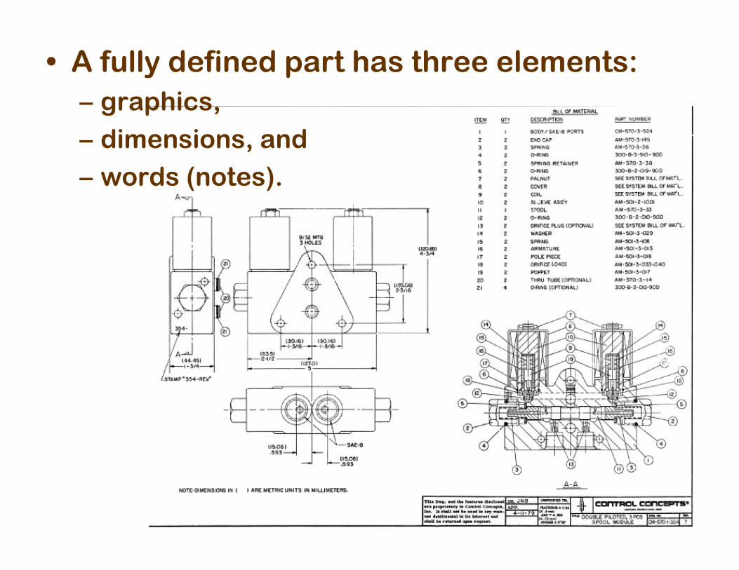
• A fully defined part has three elements: – graphics, – dimensions, and – words (notes).
SIZE AND LOCATION SIZE AND LOCATION DIMENSIONSDIMENSIONS
• A well dimensioned part will communicate the size and location requirements for each feature. Communications is the fundamental purpose of dimensions.
• Parts are dimensioned based on two criteria:– Basic size and locations of the features.– Details of a part's construction, for
manufacturing.
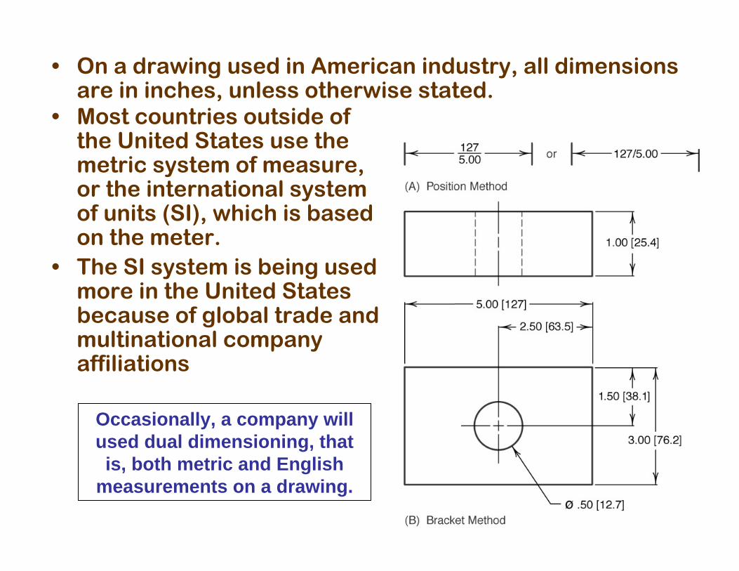
• On a drawing used in American industry, all dimensions are in inches, unless otherwise stated.
• Most countries outside of the United States use the metric system of measure, or the international system of units (SI), which is based on the meter.
• The SI system is being used more in the United States because of global trade and multinational company affiliations
Occasionally, a company will used dual dimensioning, that is, both metric and English
measurements on a drawing.
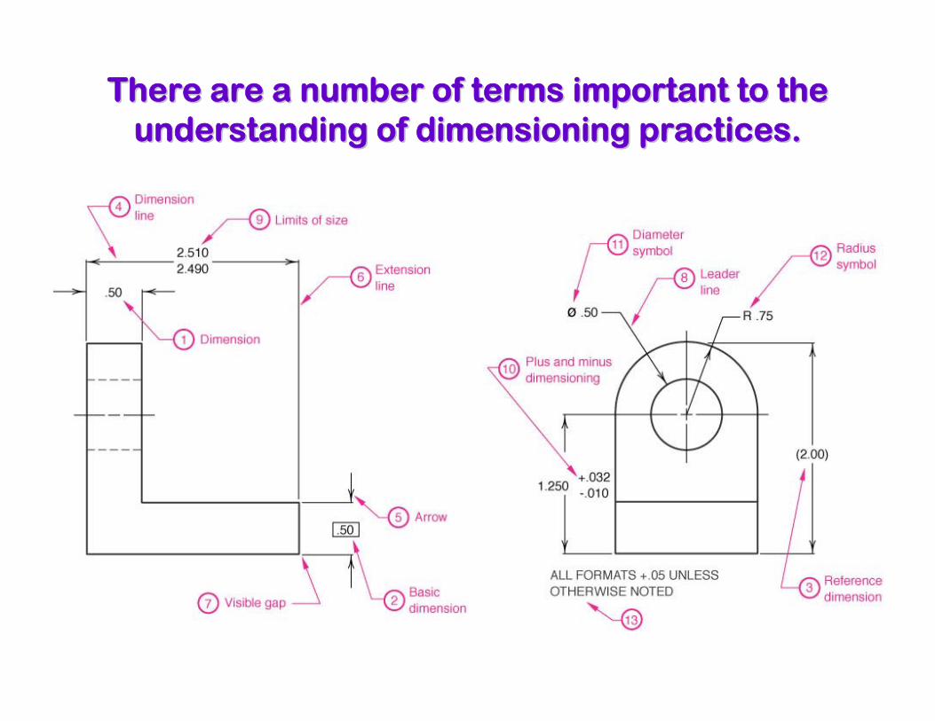
There are a number of terms important to the There are a number of terms important to the understanding of dimensioning practices.understanding of dimensioning practices.
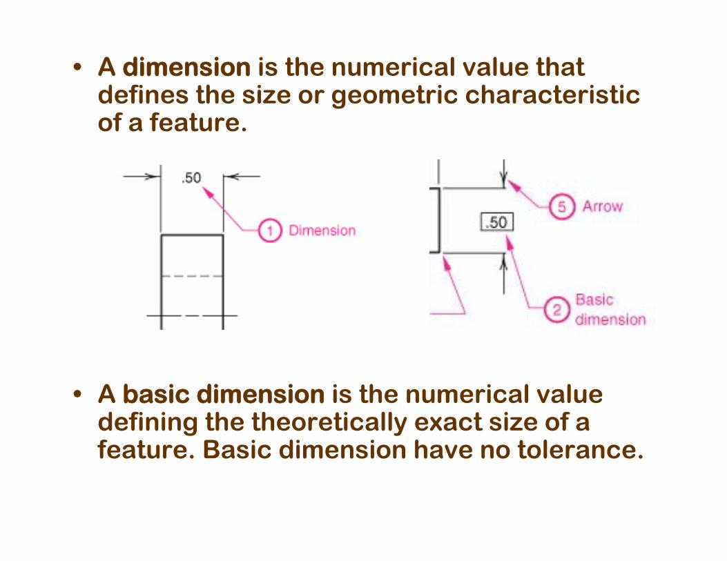
• A dimension is the numerical value that defines the size or geometric characteristic of a feature.
• A basic dimension is the numerical value defining the theoretically exact size of a feature. Basic dimension have no tolerance.
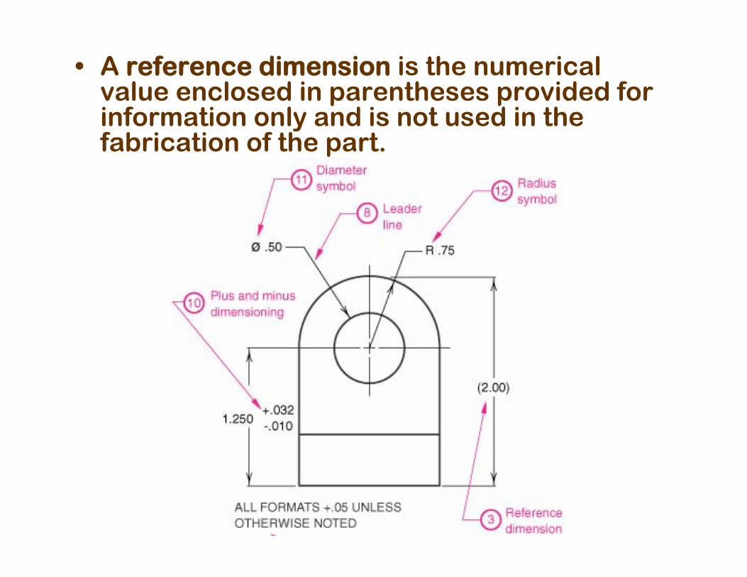
• A reference dimension is the numerical value enclosed in parentheses provided for information only and is not used in the fabrication of the part.
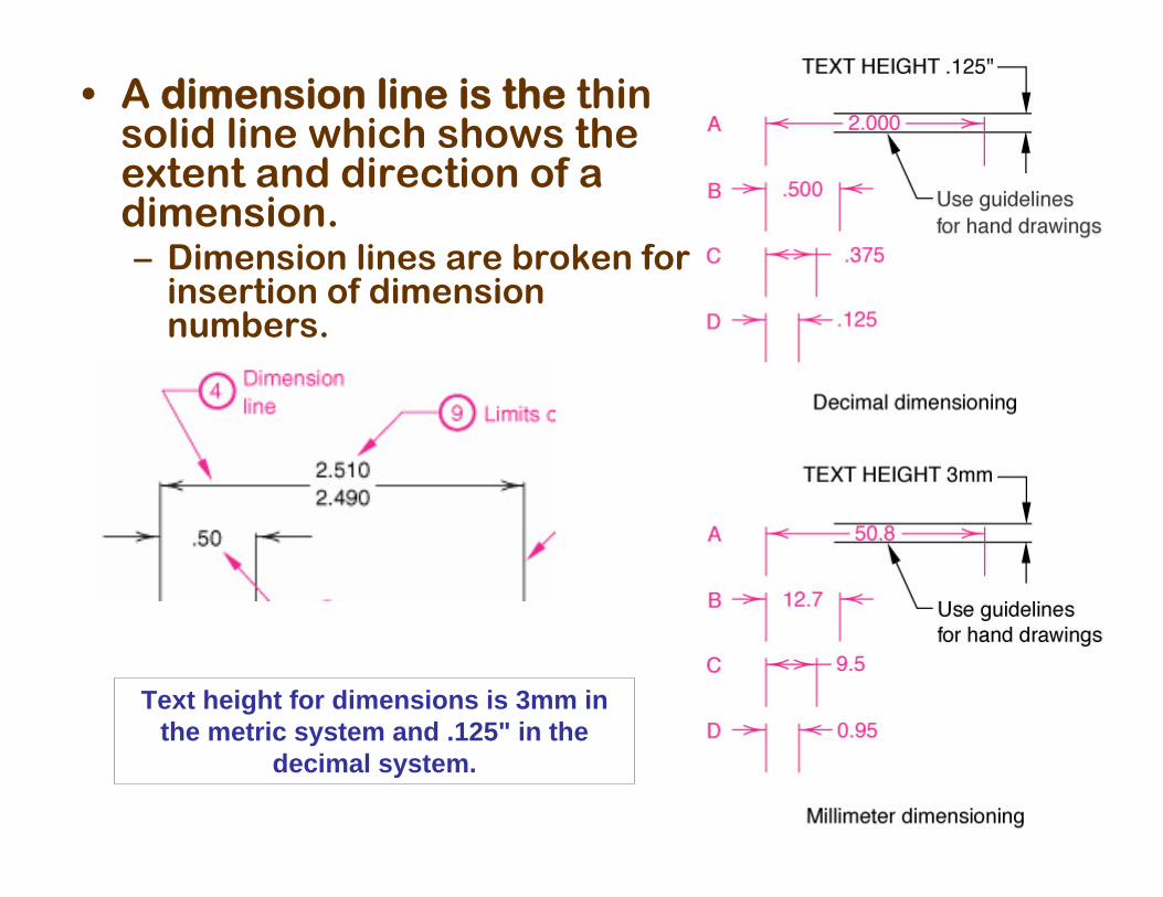
• A dimension line is the thin solid line which shows the extent and direction of a dimension. – Dimension lines are broken for
insertion of dimension numbers.
Text height for dimensions is 3mm in the metric system and .125" in the
decimal system.
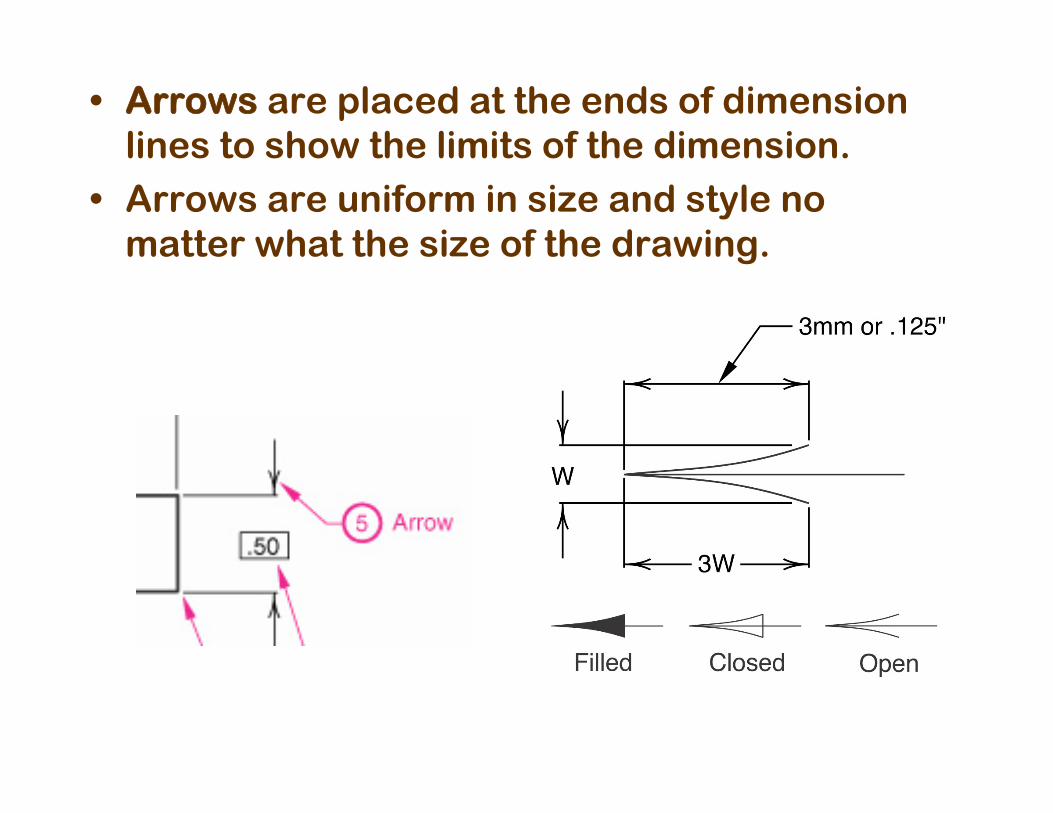
• Arrows are placed at the ends of dimension lines to show the limits of the dimension.
• Arrows are uniform in size and style no matter what the size of the drawing.
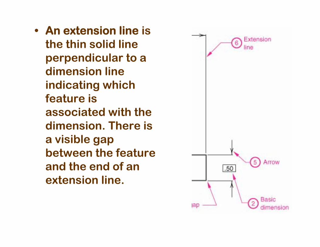
• An extension line is the thin solid line perpendicular to a dimension line indicating which feature is associated with the dimension. There is a visible gap between the feature and the end of an extension line.
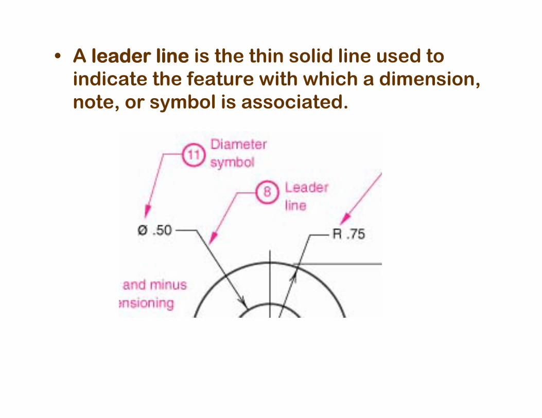
• A leader line is the thin solid line used to indicate the feature with which a dimension, note, or symbol is associated.
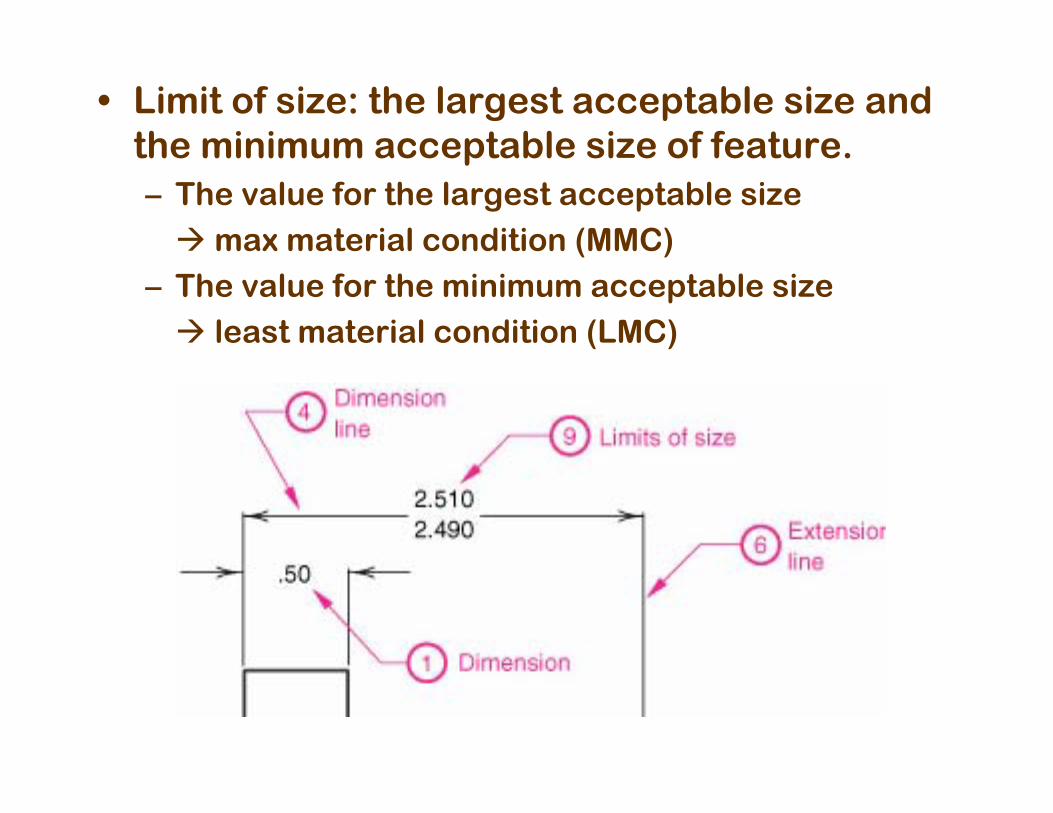
• Limit of size: the largest acceptable size and the minimum acceptable size of feature.– The value for the largest acceptable size
max material condition (MMC)– The value for the minimum acceptable size
least material condition (LMC)
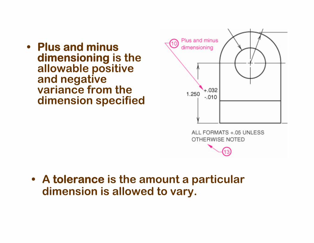
• A tolerance is the amount a particular dimension is allowed to vary.
• Plus and minus dimensioning is the allowable positive and negative variance from the dimension specified
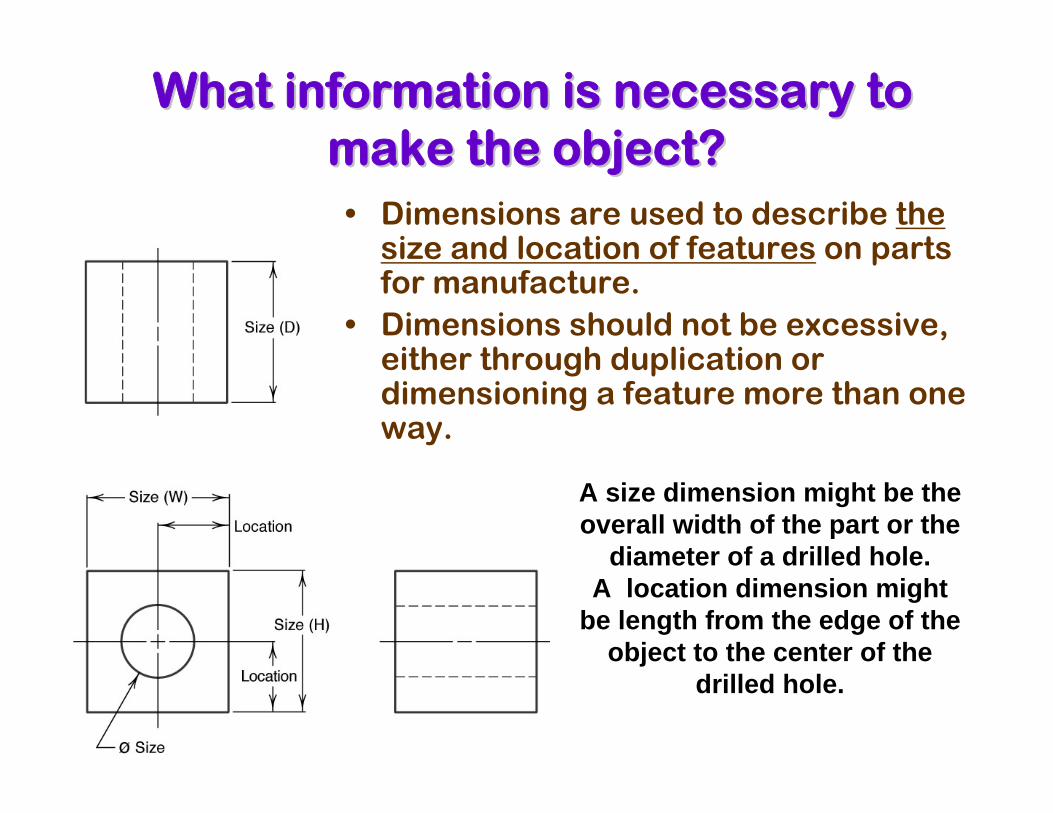
• Dimensions are used to describe the size and location of features on parts for manufacture.
• Dimensions should not be excessive, either through duplication or dimensioning a feature more than one way.
What information is necessary to What information is necessary to make the object?make the object?
A size dimension might be the overall width of the part or the
diameter of a drilled hole.A location dimension might
be length from the edge of the object to the center of the
drilled hole.
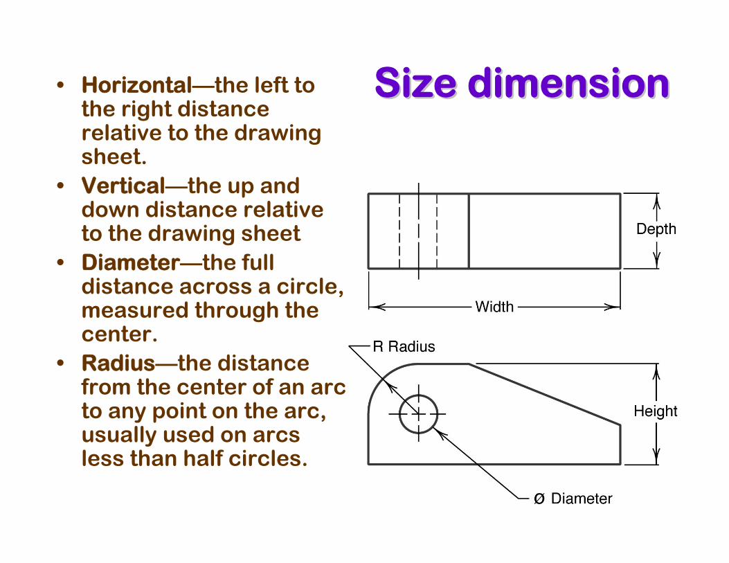
Size dimensionSize dimension• Horizontal—the left to the right distance relative to the drawing sheet.
• Vertical—the up and down distance relative to the drawing sheet
• Diameter—the full distance across a circle, measured through the center.
• Radius—the distance from the center of an arc to any point on the arc, usually used on arcs less than half circles.
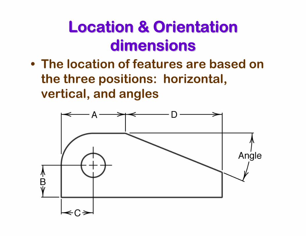
Location & Orientation Location & Orientation dimensionsdimensions
• The location of features are based on the three positions: horizontal, vertical, and angles
Coordinate dimensionCoordinate dimension
• In rectangular coordinate dimensioning, a base line (or datum line) is established for each coordinate direction, and all dimensions specified with respect to these baselines.
• This is also known as datum dimensioning, or baseline dimensioning.
• All dimensions are calculated as X and Y distances from an origin point, usually placed at the lower left corner of the part.
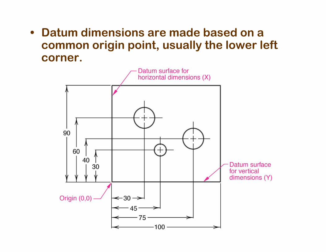
• Datum dimensions are made based on a common origin point, usually the lower left corner.
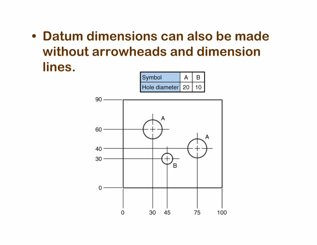
• Datum dimensions can also be made without arrowheads and dimension lines.
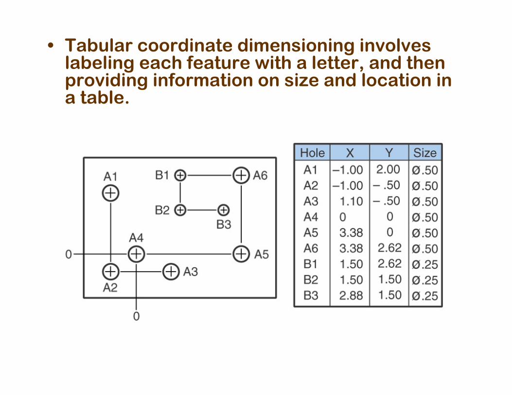
• Tabular coordinate dimensioning involves labeling each feature with a letter, and then providing information on size and location in a table.
Standard practicesStandard practices
• The guiding principal for dimensioning a drawing is clarity.
• To promote clarity, ANSI developed standard practices for showing dimensions on drawings.
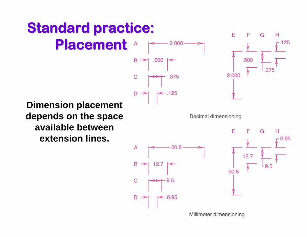
Standard practice: Standard practice: PlacementPlacement
Dimension placement depends on the space
available between extension lines.
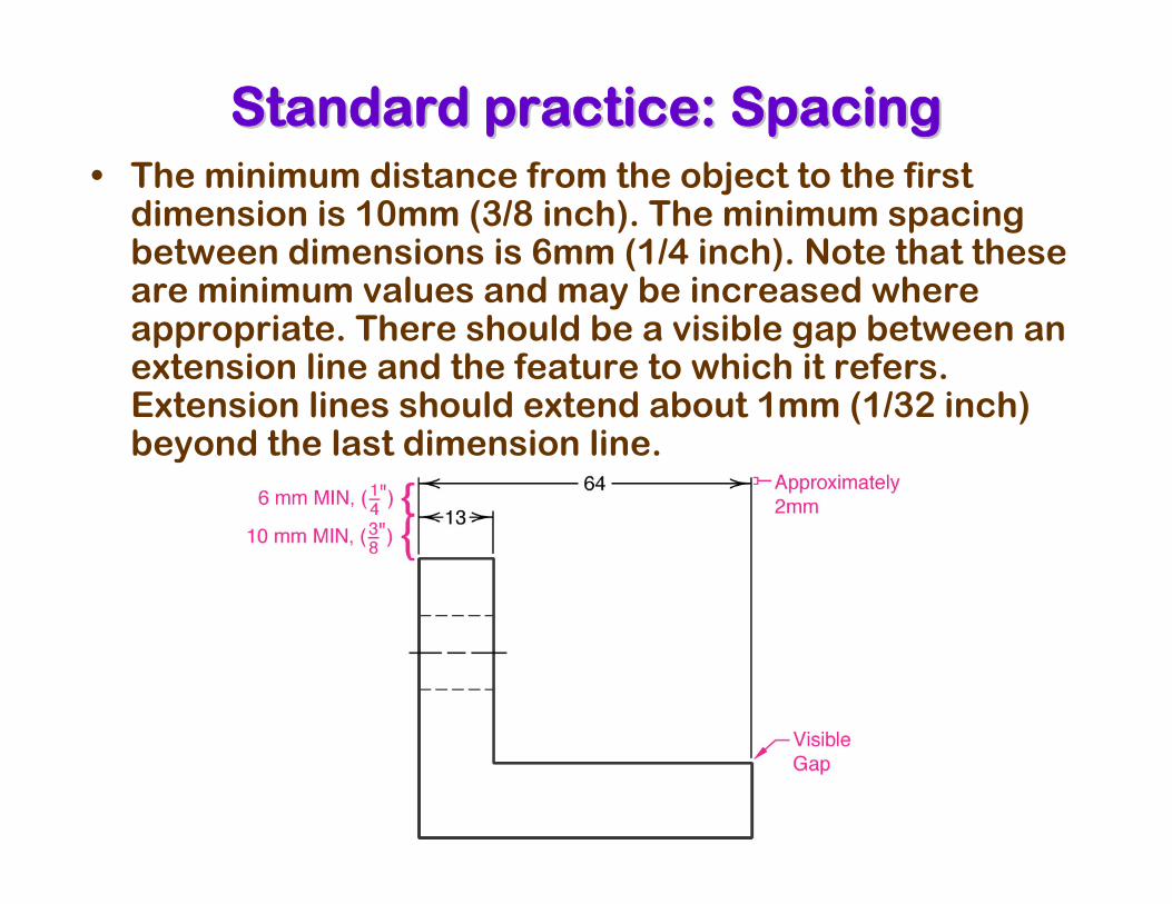
Standard practice: SpacingStandard practice: Spacing• The minimum distance from the object to the first
dimension is 10mm (3/8 inch). The minimum spacing between dimensions is 6mm (1/4 inch). Note that these are minimum values and may be increased where appropriate. There should be a visible gap between an extension line and the feature to which it refers. Extension lines should extend about 1mm (1/32 inch) beyond the last dimension line.
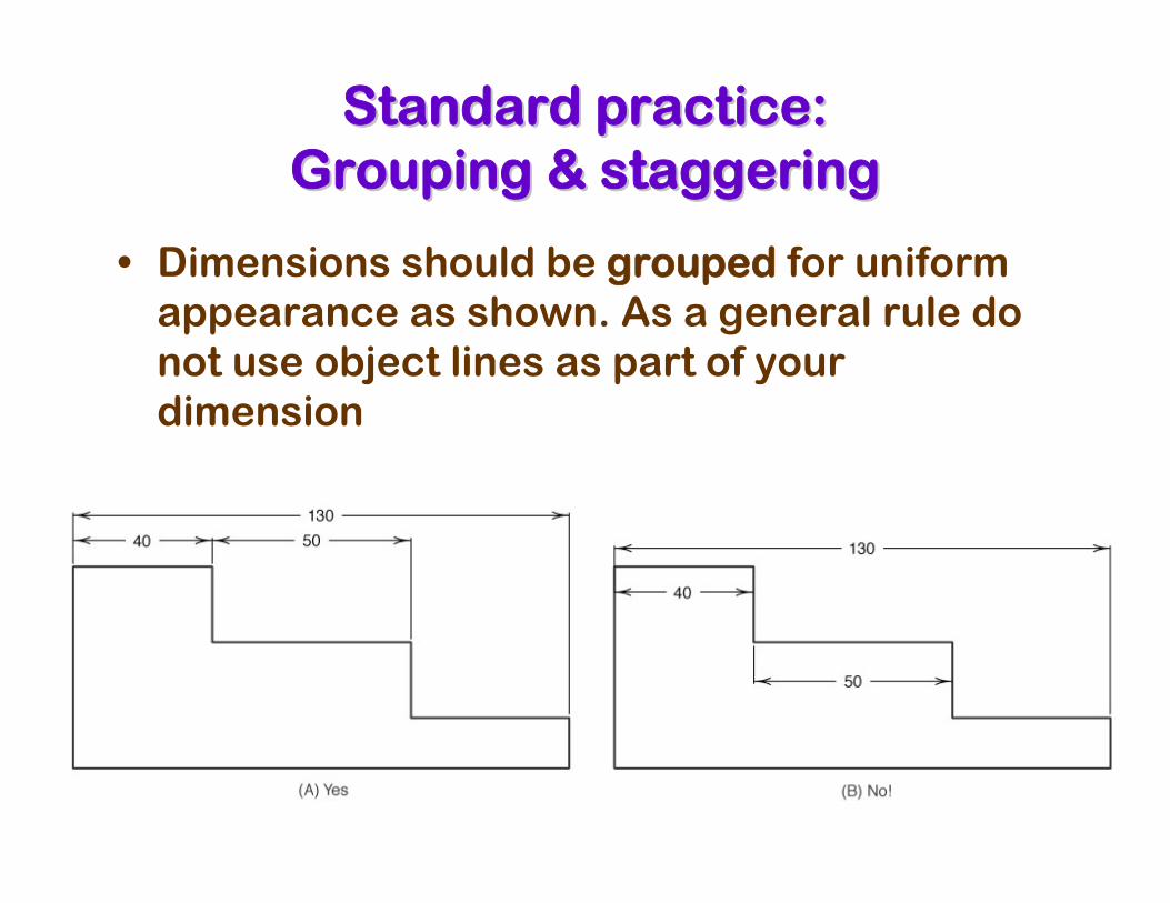
Standard practice: Standard practice: Grouping & staggeringGrouping & staggering
• Dimensions should be grouped for uniform appearance as shown. As a general rule do not use object lines as part of your dimension
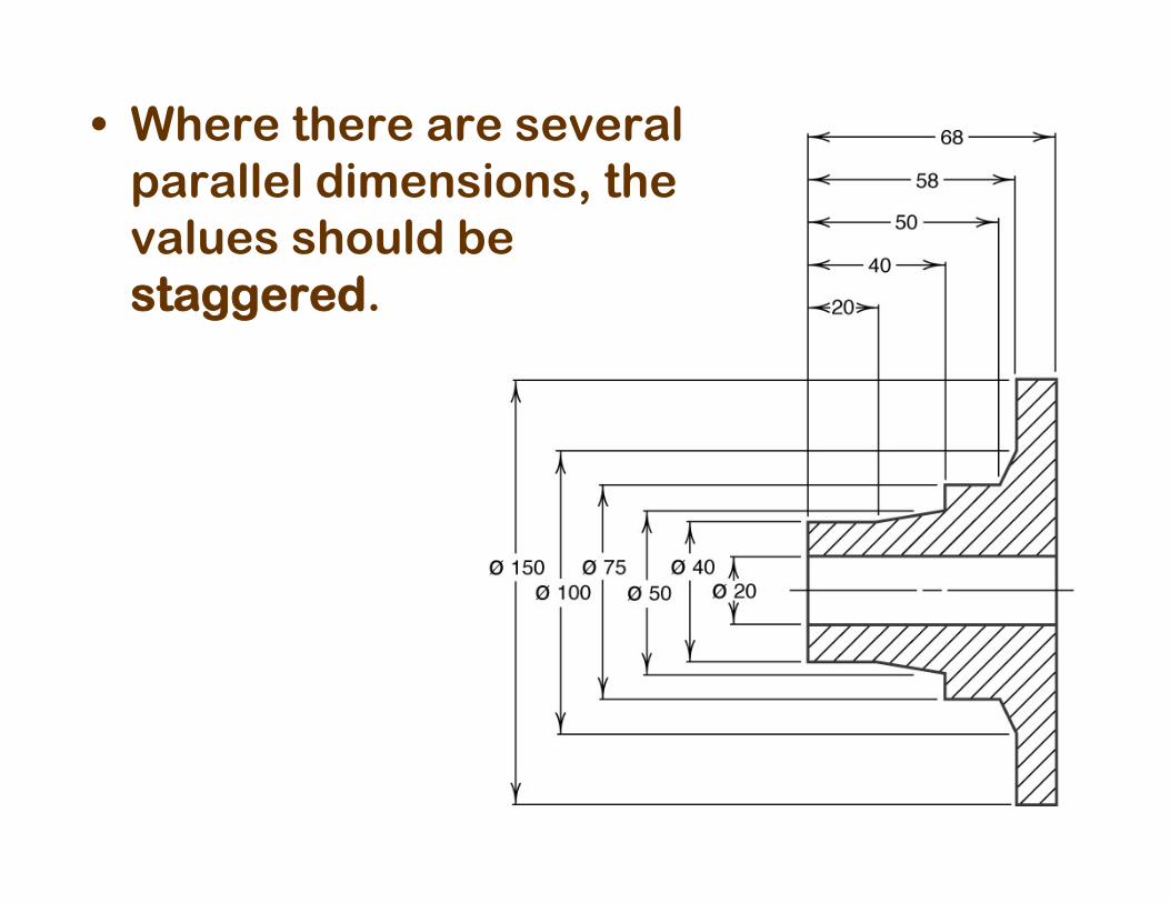
• Where there are several parallel dimensions, the values should be staggered.
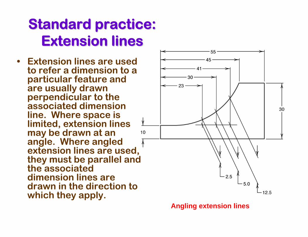
Standard practice: Standard practice: Extension lines Extension lines
• Extension lines are used to refer a dimension to a particular feature and are usually drawn perpendicular to the associated dimension line. Where space is limited, extension lines may be drawn at an angle. Where angled extension lines are used, they must be parallel and the associated dimension lines are drawn in the direction to which they apply.
Angling extension lines
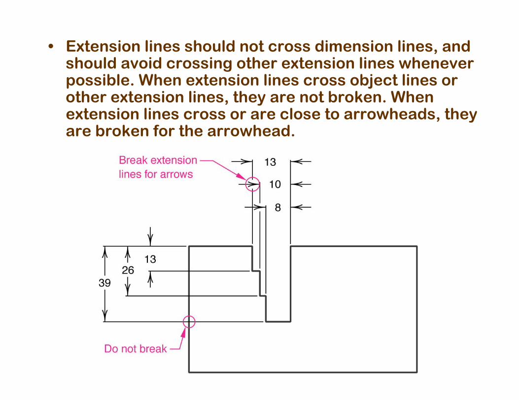
• Extension lines should not cross dimension lines, and should avoid crossing other extension lines whenever possible. When extension lines cross object lines or other extension lines, they are not broken. When extension lines cross or are close to arrowheads, they are broken for the arrowhead.
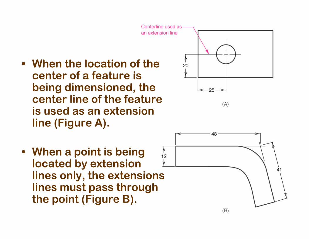
• When the location of the center of a feature is being dimensioned, the center line of the feature is used as an extension line (Figure A).
• When a point is being located by extension lines only, the extensions lines must pass through the point (Figure B).
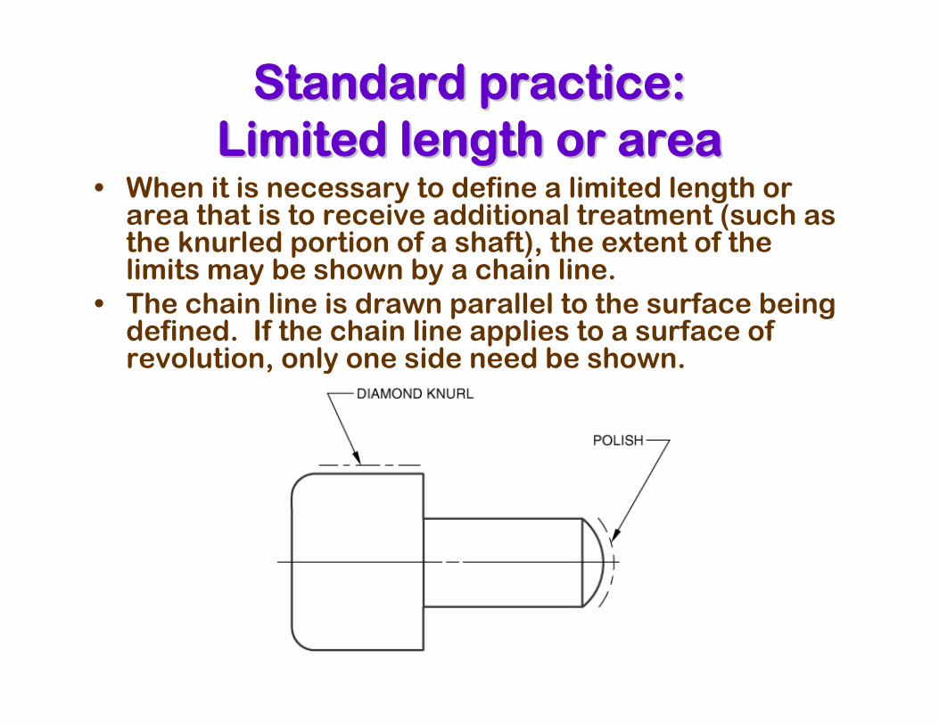
• When it is necessary to define a limited length or area that is to receive additional treatment (such as the knurled portion of a shaft), the extent of the limits may be shown by a chain line.
• The chain line is drawn parallel to the surface being defined. If the chain line applies to a surface of revolution, only one side need be shown.
Standard practice: Standard practice: Limited length or area Limited length or area
Standard practice: Standard practice: Limited length or areaLimited length or area
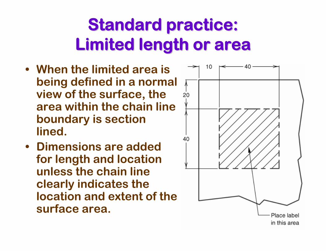
• When the limited area is being defined in a normal view of the surface, the area within the chain line boundary is section lined.
• Dimensions are added for length and location unless the chain line clearly indicates the location and extent of the surface area.
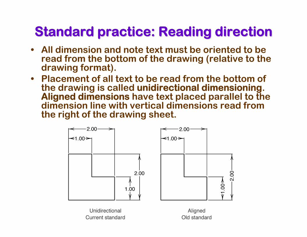
Standard practice: Reading directionStandard practice: Reading direction• All dimension and note text must be oriented to be
read from the bottom of the drawing (relative to the drawing format).
• Placement of all text to be read from the bottom of the drawing is called unidirectional dimensioning. Aligned dimensions have text placed parallel to the dimension line with vertical dimensions read from the right of the drawing sheet.
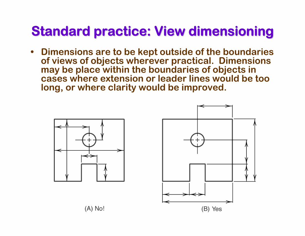
Standard practice: View dimensioningStandard practice: View dimensioning
• Dimensions are to be kept outside of the boundaries of views of objects wherever practical. Dimensions may be place within the boundaries of objects in cases where extension or leader lines would be too long, or where clarity would be improved.
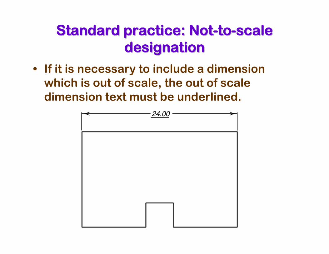
Standard practice: NotStandard practice: Not--toto--scale scale designationdesignation
• If it is necessary to include a dimension which is out of scale, the out of scale dimension text must be underlined.
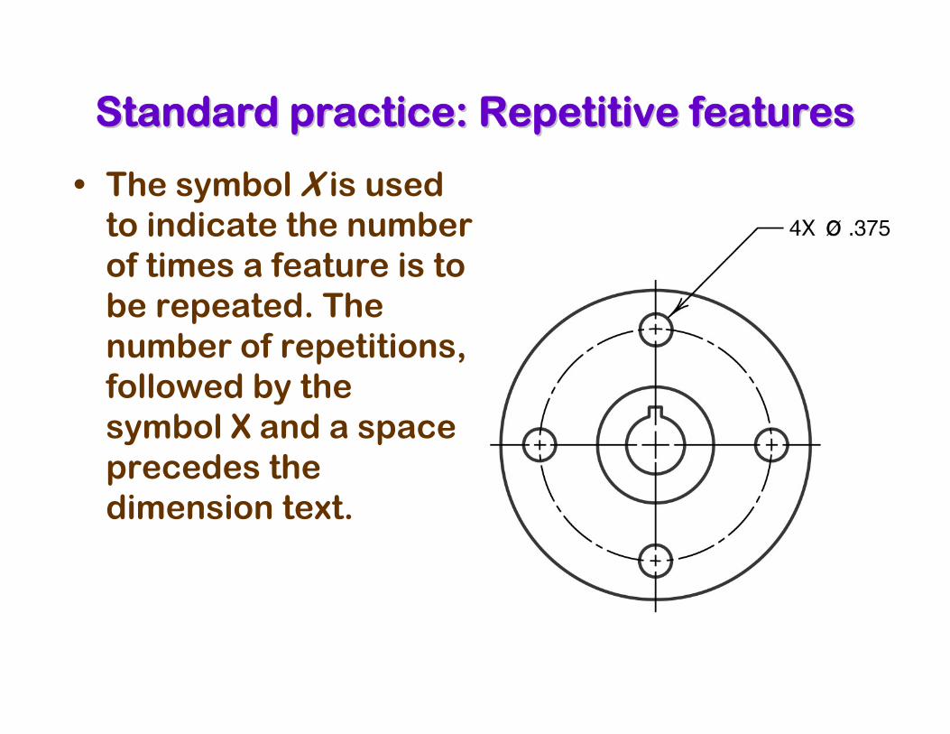
Standard practice: Repetitive featuresStandard practice: Repetitive features
• The symbol X is used to indicate the number of times a feature is to be repeated. The number of repetitions, followed by the symbol X and a space precedes the dimension text.
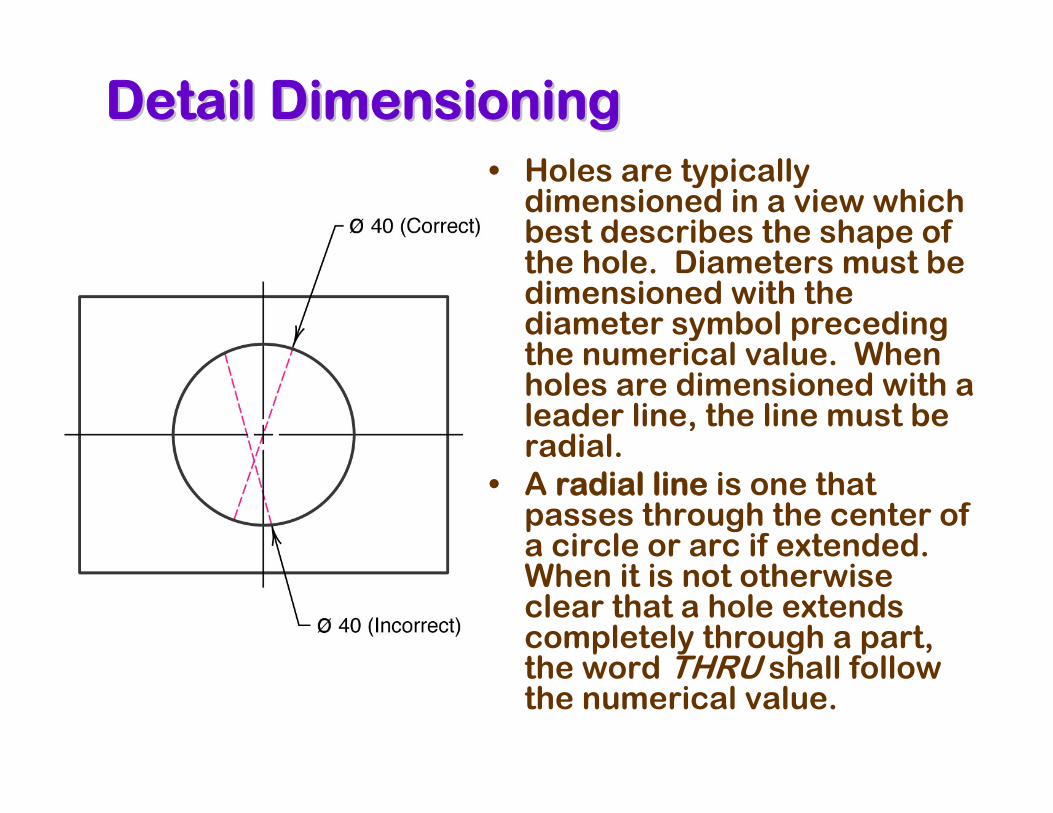
Detail DimensioningDetail Dimensioning• Holes are typically
dimensioned in a view which best describes the shape of the hole. Diameters must be dimensioned with the diameter symbol preceding the numerical value. When holes are dimensioned with a leader line, the line must be radial.
• A radial line is one that passes through the center of a circle or arc if extended. When it is not otherwise clear that a hole extends completely through a part, the word THRU shall follow the numerical value.
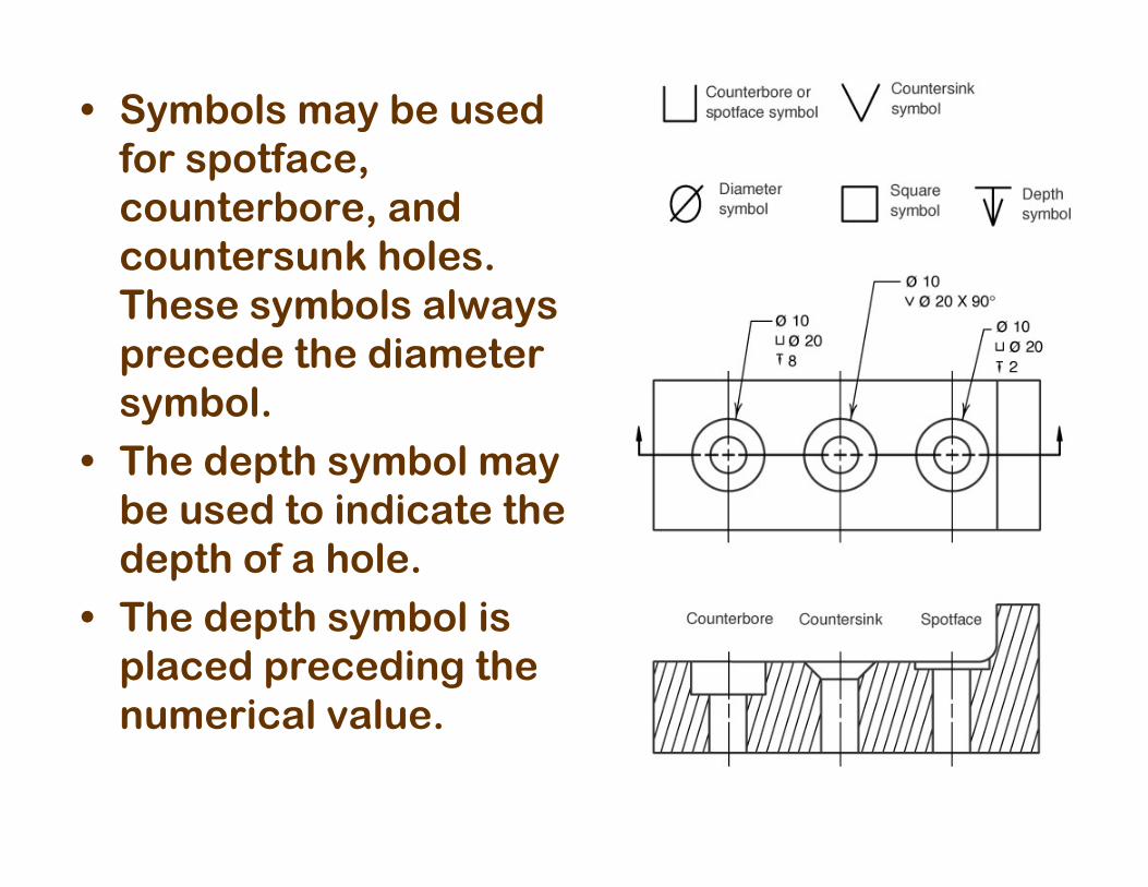
• Symbols may be used for spotface, counterbore, and countersunk holes. These symbols always precede the diameter symbol.
• The depth symbol may be used to indicate the depth of a hole.
• The depth symbol is placed preceding the numerical value.
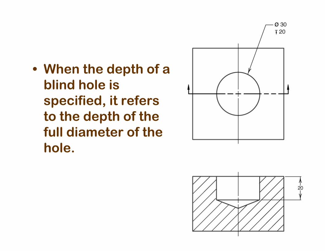
• When the depth of a blind hole is specified, it refers to the depth of the full diameter of the hole.
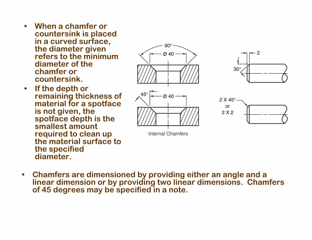
• When a chamfer or countersink is placed in a curved surface, the diameter given refers to the minimum diameter of the chamfer or countersink.
• If the depth or remaining thickness of material for a spotfaceis not given, the spotface depth is the smallest amount required to clean up the material surface to the specified diameter.
• Chamfers are dimensioned by providing either an angle and a linear dimension or by providing two linear dimensions. Chamfers of 45 degrees may be specified in a note.
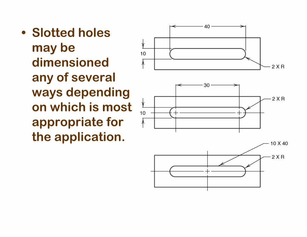
• Slotted holes may be dimensioned any of several ways depending on which is most appropriate for the application.
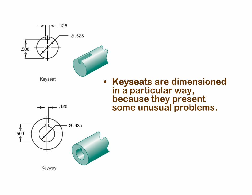
• Keyseats are dimensioned in a particular way, because they present some unusual problems.
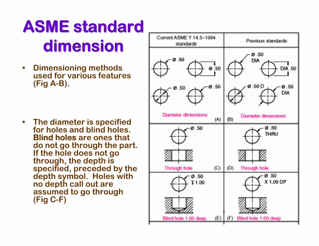
• Dimensioning methods used for various features (Fig A-B).
• The diameter is specified for holes and blind holes. Blind holes are ones that do not go through the part. If the hole does not go through, the depth is specified, preceded by the depth symbol. Holes with no depth call out are assumed to go through (Fig C-F)
ASME standard ASME standard dimensiondimension
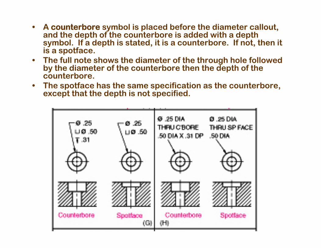
• A counterbore symbol is placed before the diameter callout, and the depth of the counterbore is added with a depth symbol. If a depth is stated, it is a counterbore. If not, then it is a spotface.
• The full note shows the diameter of the through hole followed by the diameter of the counterbore then the depth of the counterbore.
• The spotface has the same specification as the counterbore, except that the depth is not specified.
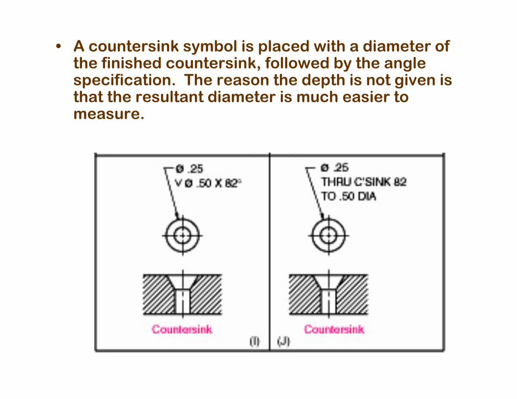
• A countersink symbol is placed with a diameter of the finished countersink, followed by the angle specification. The reason the depth is not given is that the resultant diameter is much easier to measure.
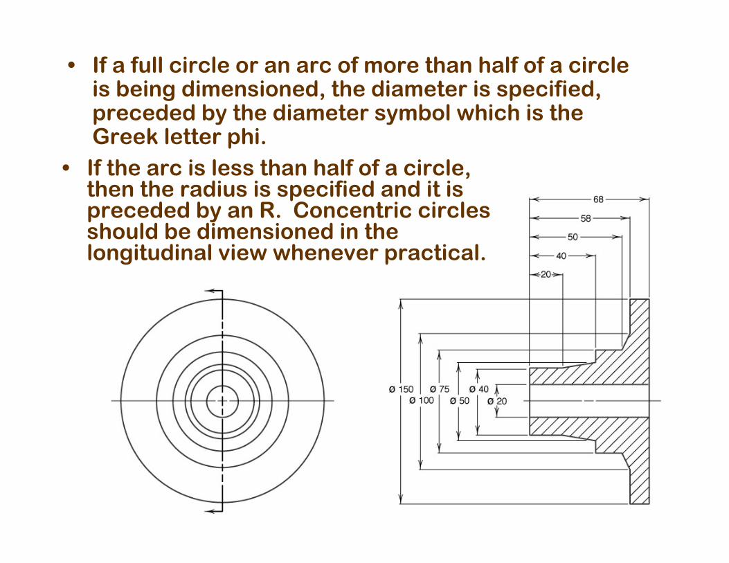
• If a full circle or an arc of more than half of a circle is being dimensioned, the diameter is specified, preceded by the diameter symbol which is the Greek letter phi.
• If the arc is less than half of a circle, then the radius is specified and it is preceded by an R. Concentric circles should be dimensioned in the longitudinal view whenever practical.
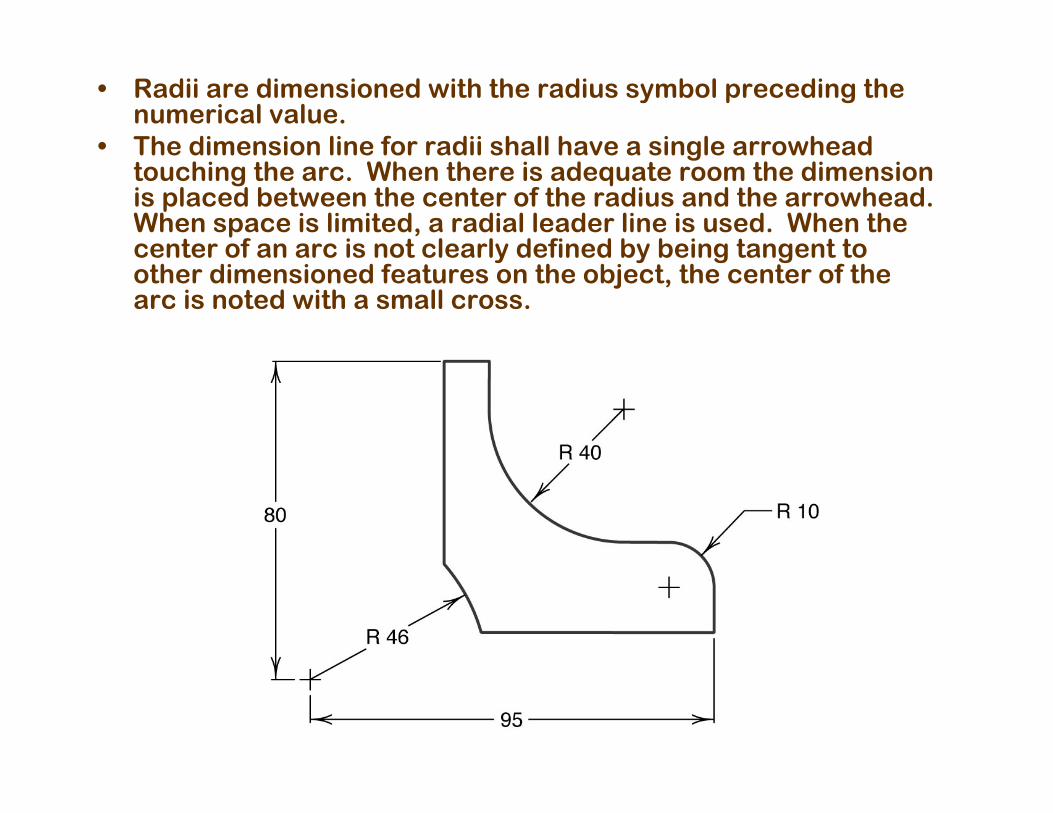
• Radii are dimensioned with the radius symbol preceding the numerical value.
• The dimension line for radii shall have a single arrowhead touching the arc. When there is adequate room the dimension is placed between the center of the radius and the arrowhead. When space is limited, a radial leader line is used. When the center of an arc is not clearly defined by being tangent to other dimensioned features on the object, the center of the arc is noted with a small cross.
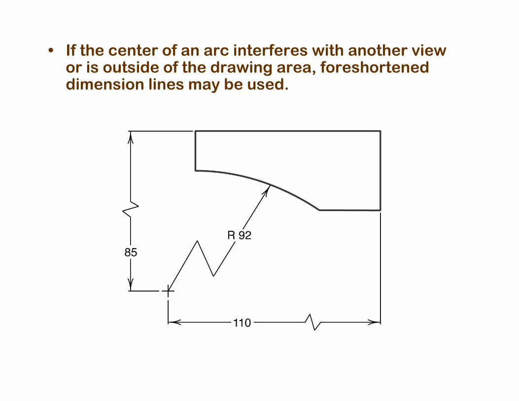
• If the center of an arc interferes with another view or is outside of the drawing area, foreshortened dimension lines may be used.
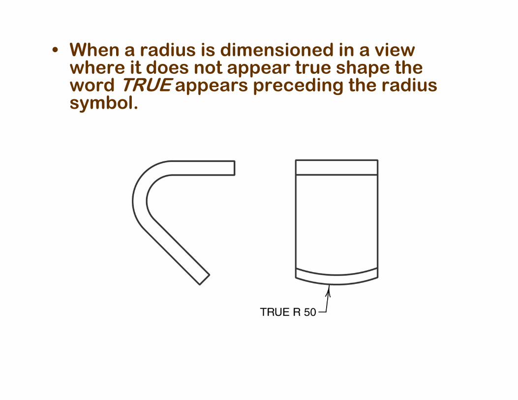
• When a radius is dimensioned in a view where it does not appear true shape the word TRUE appears preceding the radius symbol.
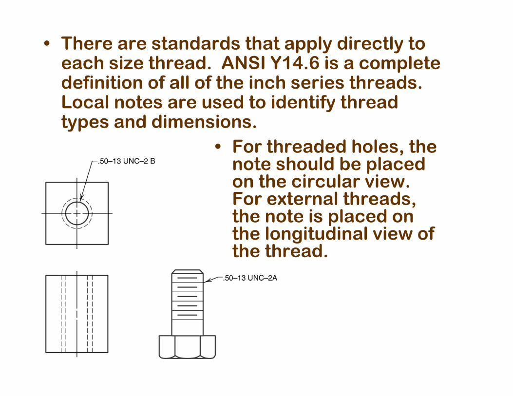
• There are standards that apply directly to each size thread. ANSI Y14.6 is a complete definition of all of the inch series threads. Local notes are used to identify thread types and dimensions.
• For threaded holes, the note should be placed on the circular view. For external threads, the note is placed on the longitudinal view of the thread.
Dimensioning techniques: Dimensioning techniques: Correct contour dimensionCorrect contour dimension
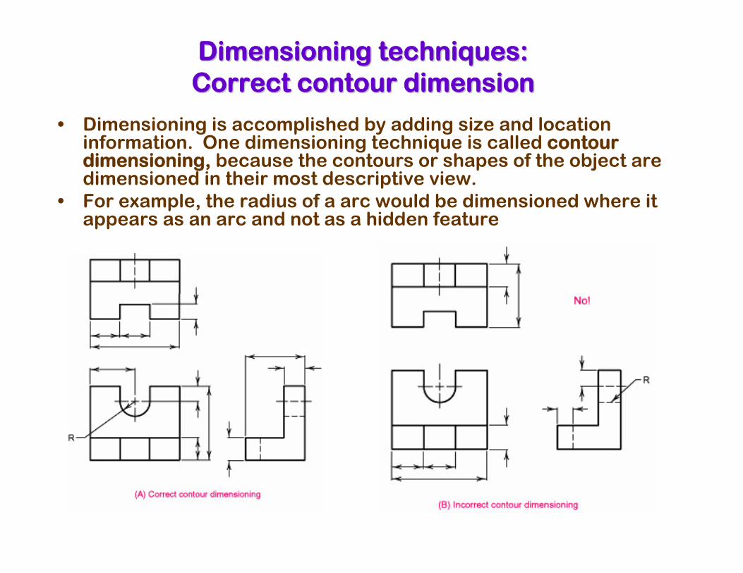
• Dimensioning is accomplished by adding size and location information. One dimensioning technique is called contour dimensioning, because the contours or shapes of the object are dimensioned in their most descriptive view.
• For example, the radius of a arc would be dimensioned where it appears as an arc and not as a hidden feature
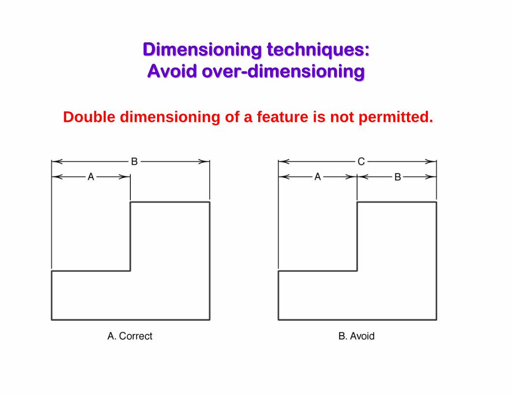
Dimensioning techniques: Dimensioning techniques: Avoid overAvoid over--dimensioningdimensioning
Double dimensioning of a feature is not permitted.
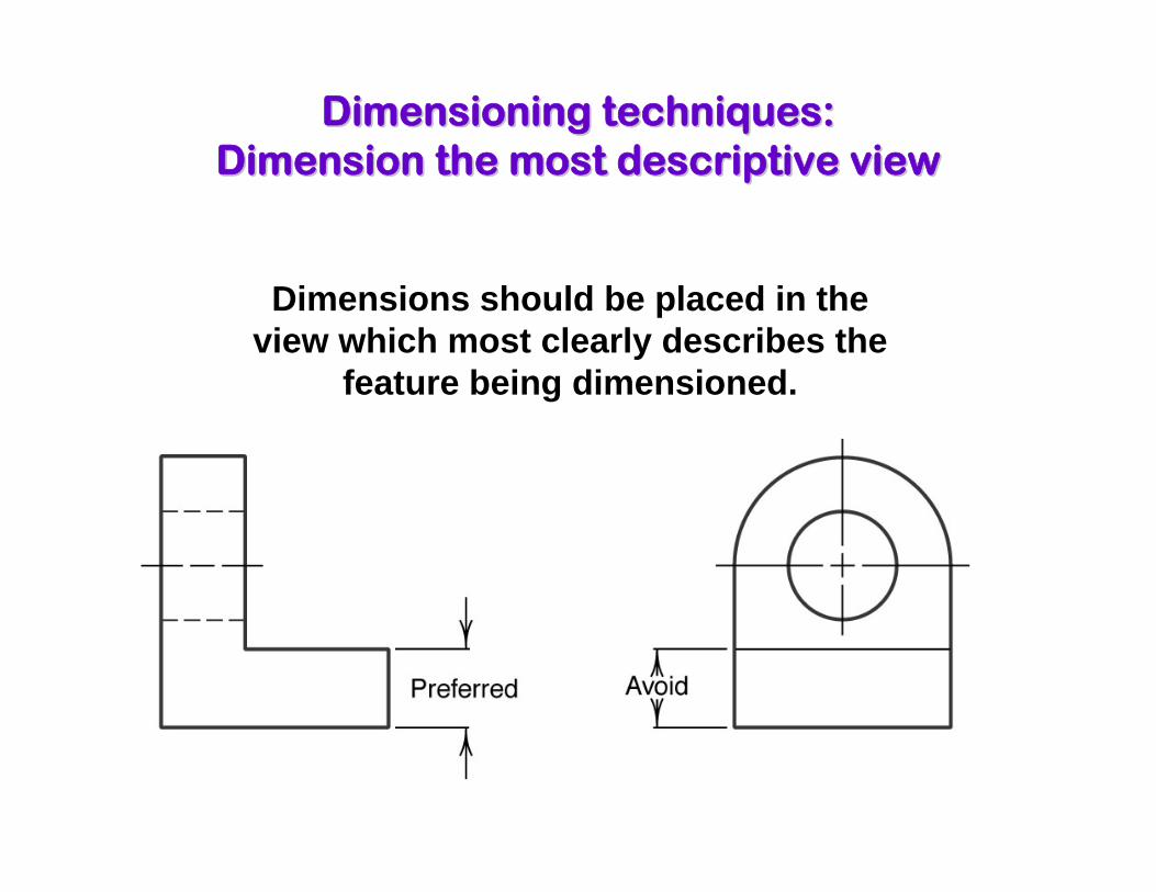
Dimensioning techniques: Dimensioning techniques: Dimension the most descriptive viewDimension the most descriptive view
Dimensions should be placed in the view which most clearly describes the
feature being dimensioned.

Will continue to GDT 2Will continue to GDT 2