9500 mpr rel.4.2.0 mss-1c mpt-hc v2 mpt-mc mpt-xp usermanual.3db19901dcaa 01
DESCRIPTION
User Manual for 9500TRANSCRIPT

Alcatel-Lucent 9500MICROWAVE PACKET RADIO for ANSI | RELEASE 4.2.0Indoor: MSS-1c + Outdoor: MPT-HC V2/MPT-XP/9558HC
Alcatel-Lucent 9500MICROWAVE PACKET RADIO for ETSI | RELEASE 4.2.0Indoor: MSS-1c + Outdoor: MPT-HC/MPT-HC V2/MPT-MC/MPT-XP
Alcatel-Lucent ProprietaryThis document contains proprietary information of Alcatel-Lucent and is not to be disclosedor used except in accordance with applicable agreements.Copyright 2013 © Alcatel-Lucent. All rights reserved.
Main Documentation
MSS-1c User Manual
User Manual3DB 19901 DCAA Edition 01

Alcatel-Lucent assumes no responsibility for the accuracy of the information presented, which is subject to change without notice.
Alcatel, Lucent, Alcatel-Lucent and the Alcatel-Lucent logo are trademarks of Alcatel-Lucent. All other trademarks are the property of their respective owners.
Copyright 2013 Alcatel-Lucent.
All rights reserved.
Disclaimers
Alcatel-Lucent products are intended for commercial uses. Without the appropriate network design engineering, they must not be sold, licensed or otherwise distributed for use in any hazardous environments requiring fail-safe performance, such as in the operation of nuclear facilities, aircraft navigation or communication systems, air traffic control, direct life-support machines, or weapons systems, in which the failure of products could lead directly to death, personal injury, or severe physical or environmental damage. The customer hereby agrees that the use, sale, license or other distribution of the products for any such application without the prior written consent of Alcatel-Lucent, shall be at the customer's sole risk. The customer hereby agrees to defend and hold Alcatel-Lucent harmless from any claims for loss, cost, damage, expense or liability that may arise out of or in connection with the use, sale, license or other distribution of the products in such applications.
This document may contain information regarding the use and installation of non-Alcatel-Lucent products. Please note that this information is provided as a courtesy to assist you. While Alcatel-Lucent tries to ensure that this information accurately reflects information provided by the supplier, please refer to the materials provided with any non-Alcatel-Lucent product and contact the supplier for confirmation. Alcatel-Lucent assumes no responsibility or liability for incorrect or incomplete information provided about non-Alcatel-Lucent products.
However, this does not constitute a representation or warranty. The warranties provided for Alcatel-Lucent products, if any, are set forth in contractual documentation entered into by Alcatel-Lucent and its customers.
This document was originally written in English. If there is any conflict or inconsistency between the English version and any other version of a document, the English version shall prevail.
User Manual
Table of Contents
9500 MPR for ANSI and ETSI
3DB19901DCAA Issue 01 1/374
TABLE OF CONTENTS
LIST OF FIGURES ......................................................................................................................... 5
LIST OF TABLES ........................................................................................................................... 11
PREFACE......................................................................................................................................... 13Preliminary information.............................................................................................................. 13Applicability................................................................................................................................. 14Scope ........................................................................................................................................... 14History.......................................................................................................................................... 14Change notes .............................................................................................................................. 15Handbook structure.................................................................................................................... 15General on Alcatel-Lucent customer documentation ............................................................. 16
0 FCC PART 15 SUBPART B......................................................................................................... 190.1 9500 MPR-A unlicensed radio............................................................................................. 190.2 FCC Class B compliance statement................................................................................... 190.3 FCC Class B requirements.................................................................................................. 19
1 SAFETY, EMC, EMF, ESD NORMS, EQUIPMENT LABELING, STANDARDS ANDCOMPLIANCE........................................................................................................................ 21
1.1 MPR-E: Declaration of conformity to CE marking and countries list ............................. 221.2 Specific label for MPR equipment ...................................................................................... 231.3 Applicable standards and recommendations ................................................................... 231.4 Safety rules........................................................................................................................... 24
1.4.1 General rules .................................................................................................................. 241.4.2 Labels Indicating danger, forbiddance, command .......................................................... 25
1.5 Electromagnetic compatibility (EMC norms) .................................................................... 281.6 Equipment protection against electrostatic discharges .................................................. 291.7 Cautions to avoid equipment damage ............................................................................... 301.8 MPR-E: Waste from electrical and electronic equipment (WEEE)................................... 301.9 Standards and compliance ................................................................................................. 31
2 PRODUCT INFORMATION AND PLANNING ............................................................................. 332.1 9500 family overview ........................................................................................................... 34
2.1.1 9500 MPR system family ................................................................................................ 392.1.2 Family elements described in this user manual .............................................................. 402.1.3 MSS-1c ........................................................................................................................... 402.1.4 MPT-HC.......................................................................................................................... 412.1.5 MPT-HC V2/9558HC ...................................................................................................... 412.1.6 MPT-XP .......................................................................................................................... 422.1.7 MPR-E: MPT-MC ............................................................................................................ 432.1.8 MSS-1c to MPT-HC interconnection............................................................................... 432.1.9 MSS-1c to MPT-HC V2/9558HC interconnection ........................................................... 462.1.10 MSS-1c to MPT-XP interconnection ............................................................................. 482.1.11 MSS-1c to MPT-MC interconnection............................................................................. 502.1.12 Antennas....................................................................................................................... 50
2.2 MPR-E: Radio capacity, channelling and modulation (MPT-HC/MPT-HC V2/MPT-MC/MPT-XP) ........................................................................................... 51
2.3 MPR-A: Radio capacity, channelling and modulation (MPT-HCV2/MPT-XP/9558HC) ........................................................................................................... 53
2.4 Standard features ................................................................................................................ 552.5 Radio configurations ........................................................................................................... 56
2.5.1 1+0 in split-mount configuration...................................................................................... 56
User Manual
Table of Contents
9500 MPR for ANSI and ETSI
3DB19901DCAA Issue 012/374
2.5.2 2x(1+0) repeater configuration........................................................................................ 572.6 Typical system configurations ........................................................................................... 572.7 Environmental and electrical characteristics.................................................................... 59
2.7.1 General characteristics (MSS-1c) ................................................................................... 592.7.2 General characteristics (MPT-HC/MPT-HC V2/MPT-XP/MPT-MC
(MPR-E)/ 9558HC (MPR-A)) .......................................................................................... 602.7.3 MPR-E: MPT-MC characteristics .................................................................................... 612.7.4 MPR-E: MPT-HC/MPT-HC V2/MPT-XP characteristics ................................................. 632.7.5 MPR-A: MPT-HC V2/9558HC characteristics................................................................. 652.7.6 Radio performances ....................................................................................................... 662.7.7 MPR-E: General characteristics (power extractor) ......................................................... 662.7.8 General characteristics (MPT Power Unit)...................................................................... 662.7.9 Maximum allowed cable lengths for MPT Power Unit .................................................... 672.7.10 General characteristics (MPT Extended Power Unit) ................................................... 672.7.11 Maximum allowed cable length for MPT Extended Power Unit ................................... 68
2.8 MPR-E: Parts lists ................................................................................................................ 692.8.1 MSS-1c ........................................................................................................................... 692.8.2 MPT-HC/MPT-HC V2/MPT-XP optical interface option .................................................. 692.8.3 MPT-HC with internal diplexer ........................................................................................ 702.8.4 MPT-HC V2 with internal diplexer................................................................................... 732.8.5 MPT-MC with internal diplexer ........................................................................................ 752.8.6 MPT-HC/MPT-HC V2/MPT-MC/MPT-XP with external diplexer ..................................... 76
2.9 MPR-A: parts lists ................................................................................................................ 842.9.1 MSS-1c ........................................................................................................................... 842.9.2 MPT-HC V2/MPT-XP/9558HC optical interface option................................................... 852.9.3 MPT-HC V2 with internal diplexer................................................................................... 852.9.4 MPT-HC V2/MPT-XP/9558HC with external diplexer ..................................................... 86
2.10 Functional description ...................................................................................................... 882.10.1 MSS-1c (indoor unit) ..................................................................................................... 882.10.2 Fan unit ......................................................................................................................... 922.10.3 MPT-HC........................................................................................................................ 932.10.4 MPR-E: power extractor ............................................................................................... 1002.10.5 MPT-HC V2/MPT-XP/9558HC...................................................................................... 1002.10.6 MPR-E: MPT-MC .......................................................................................................... 1012.10.7 MPT power unit............................................................................................................. 1022.10.8 MPT extended power unit ............................................................................................. 1032.10.9 Radio transmission features with MPT-HC/MPT-HC V2/MPT-XP/
MPT-MC/9558HC ........................................................................................................... 1032.10.10 TMN communication channels ................................................................................... 1082.10.11 Traffic profiles.............................................................................................................. 1082.10.12 Ethernet traffic management....................................................................................... 1122.10.13 Quality of services (QoS)............................................................................................ 1142.10.14 Cross-connections ...................................................................................................... 1172.10.15 Synchronization .......................................................................................................... 118
3 NE MANAGEMENT BY SOFTWARE APPLICATION................................................................. 1233.1 Security session management ........................................................................................... 1233.2 WebEML start ....................................................................................................................... 1243.3 Tool bar ................................................................................................................................. 1263.4 Alarm synthesis ................................................................................................................... 1263.5 Domain alarm synthesis area ............................................................................................. 1273.6 General information on the management state ................................................................ 1273.7 Navigator area...................................................................................................................... 128
3.7.1 Commissioning ............................................................................................................... 129
User Manual
Table of Contents
9500 MPR for ANSI and ETSI
3DB19901DCAA Issue 01 3/374
3.7.2 Performance monitoring ................................................................................................. 1703.7.3 Troubleshooting .............................................................................................................. 1813.7.4 Maintenance ................................................................................................................... 1853.7.5 Monitoring ....................................................................................................................... 185
4 INSTALLATION............................................................................................................................ 1934.1 Installation & interconnection overview ............................................................................ 1934.2 Hardware installation........................................................................................................... 198
4.2.1 Power consumption ........................................................................................................ 1984.2.2 Rack installation.............................................................................................................. 1994.2.3 MSS-1c installation ......................................................................................................... 2084.2.4 MPT-HC installation ........................................................................................................ 2164.2.5 MPT-HC V2/MPT-XP/9558HC installation...................................................................... 2534.2.6 MPT-MC installation (MPR-E)......................................................................................... 2644.2.7 Power extractor............................................................................................................... 2834.2.8 MPT extended power unit ............................................................................................... 2844.2.9 MPR-E indoor installation ............................................................................................... 2854.2.10 MPR-A indoor installation ............................................................................................. 2964.2.11 Antenna alignment ........................................................................................................ 302
4.3 Software local copy ............................................................................................................. 3094.3.1 Getting started ................................................................................................................ 3094.3.2 PC characteristics........................................................................................................... 3104.3.3 Local copy of the software package (SWP) to the PC.................................................... 3114.3.4 Local copy the WebEML to PC....................................................................................... 3124.3.5 Configure PC network card to connect to NE ................................................................. 318
5 PROVISIONING............................................................................................................................ 321
6 MAINTENANCE AND TROUBLE-CLEARING ............................................................................ 3256.1 Introduction.......................................................................................................................... 3256.2 Maintenance philosophy..................................................................................................... 3256.3 Personal computer (PC)/laptop .......................................................................................... 3266.4 Troubleshooting................................................................................................................... 326
6.4.1 Before going to site checklist .......................................................................................... 3266.4.2 Network supervision troubleshooting.............................................................................. 3276.4.3 Troubleshooting basics ................................................................................................... 3286.4.4 Relationship between the alarms on the MCT and SNMP traps..................................... 3346.4.5 Troubleshooting with MSS-1c electrical or optical connection........................................ 3376.4.6 Troubleshooting path problems ...................................................................................... 3376.4.7 Troubleshooting configuration problems......................................................................... 3396.4.8 Troubleshooting ethernet problems ................................................................................ 3396.4.9 Troubleshooting TMN problems...................................................................................... 339
6.5 Failed equipment removal and replacement ..................................................................... 3416.5.1 MSS-1c removal and replacement ................................................................................. 3416.5.2 MSS-1c replaced by MSS-1c 16PDH ............................................................................. 3416.5.3 MSS-1c 16PDH replaced by MSS-1c ............................................................................. 3416.5.4 MPT-HC removal and replacement ................................................................................ 3426.5.5 MPT-HC V2, MPT-XP, and 9558HC removal and replacement...................................... 3426.5.6 MPT-MC removal and replacement ................................................................................ 342
6.6 Cleaning................................................................................................................................ 342
7 LINE�UP AND COMMISSIONING ............................................................................................... 3457.1 Introduction.......................................................................................................................... 345
7.1.1 General ........................................................................................................................... 3457.1.2 Safety�EMC�EMF�ESD norms and cautions to avoid equipment damage................... 346
User Manual
Table of Contents
9500 MPR for ANSI and ETSI
3DB19901DCAA Issue 014/374
7.1.3 Conventions.................................................................................................................... 3467.1.4 Summary of the line�up, commissioning, and acceptance phases ................................ 3477.1.5 How to access the remote NE ........................................................................................ 349
7.2 Commissioning of STATION A � phase 1 (turn up)........................................................... 3507.2.1 Turn�on preliminary operations ...................................................................................... 3507.2.2 Powering up the MSS-1c(s) with ODU(s) connected...................................................... 351
7.3 Commissioning of STATION B � phase 1 (turn up)........................................................... 3517.4 Fine antenna alignment and preliminary checks � stations A & B ................................. 351
7.4.1 Fine antenna alignment .................................................................................................. 3517.4.2 Preliminary checks.......................................................................................................... 352
7.5 End of commissioning phase 1 (Turn up) in STATION A ................................................. 3537.6 Commissioning station A � phase 2 (acceptance test) .................................................... 353
7.6.1 Installation and cabling visual inspection........................................................................ 3547.6.2 System configuration ...................................................................................................... 3557.6.3 E1/T1 traffic..................................................................................................................... 3567.6.4 Ethernet traffic................................................................................................................. 3587.6.5 NE configuration ............................................................................................................. 3587.6.6 Data/time settings ........................................................................................................... 3587.6.7 Hop E1/T1 stability test ................................................................................................... 3597.6.8 Ethernet traffic stability test............................................................................................. 359
7.7 Commissioning station B � phase 2 (acceptance test) .................................................... 3637.8 Final operations ................................................................................................................... 3637.9 Annex A: fine antenna alignment ....................................................................................... 363
ABBREVIATIONS ............................................................................................................................ 365
User Manual
List of Figures
9500 MPR for ANSI and ETSI
3DB19901DCAA Issue 01 5/374
LIST OF FIGURES
Figure 1. 9500 MPR family overview ................................................................................................ 35Figure 2. Multiservice aggregation layer ........................................................................................... 37Figure 3. Service awareness ............................................................................................................ 38Figure 4. Packet Node ...................................................................................................................... 38Figure 5. Service-driven packet adaptive modulation ....................................................................... 39Figure 6. 9500 MPR system family ................................................................................................... 39Figure 7. MPT-HC............................................................................................................................. 41Figure 8. MPT-HC V2/9558HC ......................................................................................................... 42Figure 9. MPT-XP ............................................................................................................................. 42Figure 10. MPT-MC........................................................................................................................... 43Figure 11. MPT-HC connection (electrical cable).............................................................................. 44Figure 12. MPT-HC connection (optical cable + power supply cable to MSS-1c) ............................ 45Figure 13. MPT-HC connection (optical cable + power supply cable to station battery)................... 45Figure 14. MPT-HC V2/9558HC connection..................................................................................... 46Figure 15. MPT-HC V2/9558HC connection (optical cable + power supply cable from
MSS-1c)............................................................................................................................ 47Figure 16. MPT-HC V2/9558HC connection (optical cable + power supply cable from
station battery) .................................................................................................................. 47Figure 17. MPT-XP connection......................................................................................................... 48Figure 18. MPT-XP connection (optical cable from MSS-1c + (power supply cable from
Extended Power Unit)....................................................................................................... 49Figure 19. MPT-XP connection (optical cable + power supply cable from station battery) ............... 49Figure 20. MPT-MC connection ........................................................................................................ 50Figure 21. 1+0 in split-mount configuration....................................................................................... 56Figure 22. 2x(1+0) repeater configuration......................................................................................... 57Figure 23. TDM over ethernet packet node - mapping of E1/T1/DS1 TDM on ethernet................... 58Figure 24. TDM and ethernet terminal packet transport E1/T1/DS1 TDM and 1 radio
direction ............................................................................................................................ 58Figure 25. TDM and ethernet terminal packet transport E1/T1/DS1 TDM and 2 radio
directions -2x(1+0) repeater ............................................................................................. 59Figure 26. MSS-1c block diagram..................................................................................................... 89Figure 27. MSS-1c front view............................................................................................................ 90Figure 28. MSS-1c rear view ............................................................................................................ 90Figure 29. MSS-1c and Fan unit ....................................................................................................... 93Figure 30. MPT system..................................................................................................................... 94Figure 31. 11-38 GHz MPT-HC housing ........................................................................................... 94Figure 32. 6 GHz MPT-HC housing .................................................................................................. 95Figure 33. 7-8 GHz MPT-HC housing............................................................................................... 95Figure 34. MPT-HC block diagram ................................................................................................... 95Figure 35. 7/8 GHz MPT-HC architecture......................................................................................... 98Figure 36. 11 to 38 GHz MPT-HC architecture ................................................................................. 98Figure 37. power extractor ................................................................................................................ 100Figure 38. MPT-HC V2 housing (internal diplexer) ........................................................................... 101Figure 39. MPT-MC housing (internal diplexer) ................................................................................ 102Figure 40. MPT-MC housing (external diplexer) ............................................................................... 102Figure 41. MPT power unit................................................................................................................ 102Figure 42. MPT extended power unit ................................................................................................ 103Figure 43. Available loopbacks ......................................................................................................... 105Figure 44. Frequency plan 9558HC: 5.725 to 5.850 GHz unlicensed band (FCC Part 15
and IC RSS-210) .............................................................................................................. 108Figure 45. Traffic profiles .................................................................................................................. 109Figure 46. Traffic profiles .................................................................................................................. 110
User Manual
List of Figures
9500 MPR for ANSI and ETSI
3DB19901DCAA Issue 016/374
Figure 47. E1 Traffic in TDM2TDM profile ........................................................................................ 110Figure 48. E1 Traffic in TDM2Eth profile........................................................................................... 111Figure 49. E1 Traffic in ETH2ETH (DATA) profile ............................................................................. 112Figure 50. QoS in the MSS-1c .......................................................................................................... 114Figure 51. QoS in the MPT ............................................................................................................... 115Figure 52. Cross-connection............................................................................................................. 117Figure 53. E1/T1 from/to radio port................................................................................................... 117Figure 54. E1/T1 from/to ethernet port.............................................................................................. 118Figure 55 Session expiration message............................................................................................. 123Figure 56 Connection lost message ................................................................................................. 123Figure 57. Acknowledgement of authorization confirmation ............................................................. 125Figure 58. NEtO main view ............................................................................................................... 125Figure 59. Main view: system overview ............................................................................................ 126Figure 60. Tool bar ............................................................................................................................ 126Figure 61. Inventory .......................................................................................................................... 130Figure 62. Software download: software package versions.............................................................. 131Figure 63 Directory for the SW component if Apache FTP server is in use...................................... 132Figure 64. Software download .......................................................................................................... 133Figure 65. Software Download: Active Software Package summary ................................................ 133Figure 66. Software download: stand-by software package summary.............................................. 134Figure 67. Date/time Configuration ................................................................................................... 135Figure 68. Site information................................................................................................................ 135Figure 69. Protection configuration ................................................................................................... 136Figure 70. Warning screen................................................................................................................ 137Figure 71. Radio configuration: FCM - RTPC ................................................................................... 139Figure 72. Radio configuration: FCM - ATPC ................................................................................... 139Figure 73. Radio configuration: ACM - RTPC................................................................................... 140Figure 74. Advanced radio configuration .......................................................................................... 140Figure 75. MSS-1c ............................................................................................................................ 141Figure 76. Ethernet ports provisioning .............................................................................................. 146Figure 77. Cross connection TDM2TDM (E1 case) .......................................................................... 148Figure 78. One shot tributaries provisioning ..................................................................................... 148Figure 79. Cross connection functional scheme ............................................................................... 149Figure 80. Cross connection TDM2TDM (T1 case) .......................................................................... 150Figure 81. Cross connection to user ethernet port............................................................................ 151Figure 82. Cross connection functional scheme ............................................................................... 152Figure 83. Management port provisioning ........................................................................................ 153Figure 84. TDM cross connection between radio and ethernet port ................................................. 154Figure 85. Cross connection functional scheme ............................................................................... 154Figure 86. Network synchronization clock provisioning .................................................................... 155Figure 87. NE bridge mode selection................................................................................................ 156Figure 88. NE bridge mode selection................................................................................................ 157Figure 89. Port VLAN provisioning.................................................................................................... 158Figure 90. Port VLAN provisioning.................................................................................................... 159Figure 91. Storm control and rate limiting ......................................................................................... 160Figure 92. Per flow policer ................................................................................................................ 161Figure 93. Network interfaces ........................................................................................................... 162Figure 94. TMN RF network interface in-band.................................................................................. 162Figure 95. Areas ............................................................................................................................... 163Figure 96. OSPF Areas Management............................................................................................... 163Figure 97. Configuration message.................................................................................................... 164Figure 98. Areas ............................................................................................................................... 164Figure 99. Configuration message.................................................................................................... 164Figure 100. Areas ............................................................................................................................. 164
User Manual
List of Figures
9500 MPR for ANSI and ETSI
3DB19901DCAA Issue 01 7/374
Figure 101. Modify OSPF Area......................................................................................................... 164Figure 102. Interfaces ....................................................................................................................... 165Figure 103. Network interfaces attachment to an OSPF Area.......................................................... 165Figure 104. Interfaces ....................................................................................................................... 165Figure 105. Network interfaces attachment to an OSPF Area.......................................................... 165Figure 106. Static routing .................................................................................................................. 166Figure 107. Routing table.................................................................................................................. 167Figure 108. Trusted SNMP managers .............................................................................................. 168Figure 109. Manager registration...................................................................................................... 169Figure 110. Backup / restore ............................................................................................................. 170Figure 111. Performance history file upload...................................................................................... 172Figure 112. Qos ethernet counter period duration ............................................................................ 172Figure 113. Counter Thresholds ....................................................................................................... 173Figure 114. 15Min counter activation ................................................................................................ 174Figure 115. 15Min counter ................................................................................................................ 174Figure 116. 15Min counter history..................................................................................................... 175Figure 117. 15Min counter deactivation ............................................................................................ 175Figure 118. Import history ................................................................................................................. 176Figure 119. File selection .................................................................................................................. 176Figure 120. Adaptive modulation counter activation ......................................................................... 177Figure 121. 15Min counter ................................................................................................................ 178Figure 122. 15Min counter history .................................................................................................... 178Figure 123. 15Min counter deactivation............................................................................................ 179Figure 124. Ethernet: QoS counters ................................................................................................. 180Figure 125. QoS counters example for aggregate............................................................................ 181Figure 126. Inventory ........................................................................................................................ 182Figure 127. Loopback activation ....................................................................................................... 183Figure 128. ACM manual management ............................................................................................ 184Figure 129. ATPC manual management (ANSI market only) ........................................................... 184Figure 130. Maintenance .................................................................................................................. 185Figure 131. NE Alarms...................................................................................................................... 187Figure 132. Alarm filtering................................................................................................................. 187Figure 133. Peripheral NE Alarms .................................................................................................... 188Figure 134. Power measurements.................................................................................................... 188Figure 135. Power measurements.................................................................................................... 189Figure 136. Modem measurements .................................................................................................. 190Figure 137. Modem measurements .................................................................................................. 191Figure 138. Events............................................................................................................................ 192Figure 139 Station interconnections with MPT-MC ........................................................................... 193Figure 140 Station interconnections with MPT-HC with Power Extractor ......................................... 194Figure 141 Station interconnections with MPT-HC (optical cable + coax. power supply
cable to MSS-1c) .............................................................................................................. 194Figure 142 Station interconnections with MPT-HC (optical cable + coax. power supply
cable to station battery) .................................................................................................... 195Figure 143 Station interconnections with MPT-HC V2/9558HC (one cable)..................................... 195Figure 144 Station interconnections with MPT-HC V2/9558HC (optical cable + coax.
power supply cable to MSS-1c) ........................................................................................ 196Figure 145 Station interconnections with MPT-HC V2/9558HC (optical cable + coax.
power supply cable to Station battery).............................................................................. 196Figure 146 Station interconnections with MPT-XP (PFoE) ............................................................... 197Figure 147 Station interconnections with MPT-XP (optical cable to MSS-1c + coax.
power supply cable to MPT Extended Power Unit) .......................................................... 197Figure 148 Station interconnections with MPT-XP (optical cable + coax. power supply
cable to Station battery) .................................................................................................... 198
User Manual
List of Figures
9500 MPR for ANSI and ETSI
3DB19901DCAA Issue 018/374
Figure 149 Fixing the rack to floor (1) ............................................................................................... 201Figure 150 Fixing the rack to floor (2) ............................................................................................... 202Figure 151 Floor file drilling template................................................................................................ 203Figure 152 Example of securing rack assembly to computer floor ................................................... 204Figure 153 Laborack ......................................................................................................................... 205Figure 154 TRU (6 fuse holders) shown without cover..................................................................... 206Figure 155 TRU (10 breakers slots) shown without cover ................................................................ 206Figure 156 TRU (20 breakers slots) shown without cover ................................................................ 207Figure 157 Breaker adding ............................................................................................................... 207Figure 158 TRU shown with cover.................................................................................................... 207Figure 159 Grounding ....................................................................................................................... 209Figure 160 Grounding ....................................................................................................................... 209Figure 161 Power/return connection................................................................................................. 210Figure 162 Installation solution ......................................................................................................... 210Figure 163 Installation solution ......................................................................................................... 211Figure 164 Installation solution ......................................................................................................... 211Figure 165 Interconnections to connector support 1.6/5.6 75 ohm panel 1U
(3CC08061AAAA) ............................................................................................................ 212Figure 166 Interconnections to connector support BNC 75 ohm Panel 1U
(3CC08061ABAA) ............................................................................................................ 212Figure 167 Interconnections to support 19 Inch modules 120 ohm Panel 3U
(3CC07810AAAA) ............................................................................................................ 213Figure 168 Interconnections to the E1 distributor (3CC07810AAAA (part 1)) .................................. 213Figure 169 Interconnections to the E1 distributor (3CC07810AAAA (part 2)) .................................. 214Figure 170 Interconnections to T1 connectors 37 position D-Sub cable (PN: 3EM23110AX) .......... 214Figure 171 Views of MPT-HC with embedded diplexer (11-38 GHz)................................................ 217Figure 172 Views of MPT-HC with embedded diplexer (6 GHz)....................................................... 218Figure 173 Views of MPT-HC with external diplexer......................................................................... 218Figure 174 Views of MPT-HC with embedded diplexer (11-38 GHz)................................................ 220Figure 175 Views of MPT-HC with external diplexer......................................................................... 221Figure 176 Views of MPT-HC with embedded diplexer (6 GHz)....................................................... 222Figure 177 Composition of MPT-HC with external diplexer .............................................................. 223Figure 178 MPT-HC TRANSCEIVER and BRANCHING boxes coupling surfaces .......................... 224Figure 179 Label affixed on the MPT-HC and MPT-HC TRANSCEIVER box .................................. 225Figure 180 Label affixed inside the MPT-HC BRANCHING box....................................................... 226Figure 181 MPT-HC with embedded diplexer polarization................................................................ 227Figure 182 MPT-HC with external diplexer polarization.................................................................... 228Figure 183 Example of integrated antenna pole mounting (with antenna and nose
adapter) ............................................................................................................................ 229Figure 184 "Pole Mounting for Remote ODU" installation kit (3DB10137AAXX) .............................. 229Figure 185 Example of antenna polarization change (�1+0� MPT-HC integrated antenna).............. 230Figure 186 Putting silicone grease on O-ring before MPT-HC insertion........................................... 231Figure 187 MPT-HC 1+0 installation for integrated antenna (embedded diplexer)........................... 231Figure 188 MPT-HC 1+0 installation for integrated antenna (external diplexer: vertical
polarization) ...................................................................................................................... 232Figure 189 MPT-HC 1+0 installation for integrated antenna (external diplexer:
horizontal polarization)...................................................................................................... 232Figure 190 "Pole Mounting for Remote ODU" installation................................................................. 233Figure 191 Putting silicone grease on O-ring before MPT-HC insertion........................................... 233Figure 192 MPT-HC 1+0 installation for not integrated antenna (embedded
diplexer GHz with pole mounting P/N 3DB10137AAXX) .................................................. 234Figure 193 MPT-HC 1+0 installation for not integrated antenna (external diplexer with
pole mounting P/N 3DB10137AAXX) ............................................................................... 234Figure 194 MPT-HC system ground connector ................................................................................ 249
User Manual
List of Figures
9500 MPR for ANSI and ETSI
3DB19901DCAA Issue 01 9/374
Figure 195 Example 9500 MPR/9558HC system ground plate ........................................................ 249Figure 196 Locations for cable grounds............................................................................................ 250Figure 197 Example of realization .................................................................................................... 252Figure 198 Detail of the waterproofing of the kit ............................................................................... 253Figure 199 Views of MPT-HC V2 with embedded diplexer ............................................................... 254Figure 200 RPS module.................................................................................................................... 256Figure 201 XPIC + RPS module ....................................................................................................... 256Figure 202 External module installed................................................................................................ 257Figure 203 Correct screw position .................................................................................................... 257Figure 204 Views of MPT-HC V2 with embedded diplexer ............................................................... 259Figure 205 Views of MPT-HC V2/MPT-XP/9558HC with external diplexer ...................................... 260Figure 206 Label affixed on the MPT-HC V2/MPT-XP/9558HC and MPT-HC
V2/MPT-XP/9558HC TRANSCEIVER box ....................................................................... 261Figure 207 Label affixed inside the MPT-HC V2/MPT-XP/9558HC BRANCHING box..................... 262Figure 208 LC/Q-XCO to LC fiber cord............................................................................................. 263Figure 209 Fiber cable overlength box ............................................................................................. 264Figure 210 Views of MPT-MC with embedded diplexer .................................................................... 266Figure 211 Views of MPT-MC with external diplexer......................................................................... 266Figure 212 Views of MPT-MC with embedded diplexer .................................................................... 268Figure 213 Views of MPT-MC with external diplexer ........................................................................ 268Figure 214 Composition of MPT-MC with external diplexer .............................................................. 269Figure 215 MPT-MC TRANSCEIVER and BRANCHING boxes coupling surfaces .......................... 270Figure 216 Label affixed on the MPT-MC and MPT-MC TRANSCEIVER box.................................. 271Figure 217 Label affixed inside the MPT-MC BRANCHING box....................................................... 272Figure 218 Example of antenna polarization change (�1+0� MPT-MC integrated antenna).............. 275Figure 219 Putting silicone grease on O-ring before MPT-MC insertion........................................... 275Figure 220 MPT-MC 1+0 installation for integrated antenna (6 GHz and 11-38 GHz)...................... 276Figure 221 MPT-MC 1+0 installation for integrated antenna (7-8 GHz: vertical polarization)........... 276Figure 222 MPT-MC 1+0 installation for integrated antenna (7-8 GHz: horizontal
polarization) ...................................................................................................................... 277Figure 223 "Pole Mounting for Remote ODU" installation................................................................. 278Figure 224 Putting silicone grease on O-ring before MPT-MC insertion........................................... 278Figure 225 MPT-MC 1+0 installation for not integrated antenna (with pole mounting P/N
3DB10137AAXX).............................................................................................................. 278Figure 226 Kit plug R2CT ................................................................................................................. 279Figure 227 Kit plug R2CT items........................................................................................................ 279Figure 228 MPT service cord............................................................................................................ 304Figure 229 Checking feedhead flange with a spirit level................................................................... 306Figure 230 Indicative head-on signal pattern for a parabolic antenna .............................................. 308Figure 231 Example Tracking Path Signals ...................................................................................... 309Figure 232 Example tracking path signals on the first side lobe....................................................... 309Figure 233 Directory for the SW component if Apache FTP server is in use.................................... 312Figure 234. PC connection (MPT-MC/MPT-HC) ............................................................................... 321Figure 235. PC connection (MPT-HC V2 and MPT-XP): two different solutions .............................. 322Figure 236. Relative positions of stations A and B ........................................................................... 347Figure 237. How to access the remote NE ....................................................................................... 349Figure 238. Test bench for tributary functionality check with MPT-HC/MPT-HC
V2/MPT-MC/MPT-XP........................................................................................................ 357Figure 239. Test bench for tributary functionality check with MPT-HC/MPT-HC/
V2/MPT-MC/MPT-XP/9558HC ......................................................................................... 359Figure 240. Test bench for optional Ethernet Data Channel functionality with 1
additional PC and 1 Ethernet cable .................................................................................. 361Figure 241. Test bench for optional ethernet data channel functionality with 2 additional PCs ........ 362

User Manual
List of Figures
9500 MPR for ANSI and ETSI
3DB19901DCAA Issue 0110/374
Figure 242. Test bench for optional ethernet data channel functionality with 2 ethernetdata analyzers .................................................................................................................. 363
User Manual
List of Tables
9500 MPR for ANSI and ETSI
3DB19901DCAA Issue 01 11/374
LIST OF TABLES
Table 1. Standards and compliance .................................................................................................. 31Table 2. Radio capacity, channelling scheme and modulation (static modulation) ........................... 51Table 3. Radio capacity, channelling scheme and modulation (adaptive modulation) ...................... 52Table 4. Radio capacity, channelling scheme and modulation (static modulation) ........................... 53Table 5. Radio capacity, channelling scheme and modulation (adaptive modulation) ...................... 54Table 6. MPR-E MSS-1c item codes................................................................................................. 69Table 7. MPR-E CD-ROM software codes........................................................................................ 69Table 8. MPR-E MPT-HC/MPT-HC V2/MPT-XP option .................................................................... 69Table 9. MPR-E MPT-HC codes with internal diplexer...................................................................... 70Table 10. MPR-E MPT-HC V2 codes with internal diplexer .............................................................. 73Table 11. MPR-E MPT-MC codes with internal diplexer.................................................................... 75Table 12. MPR-E 6, 7, and 8 GHz MPT-MC codes with external diplexer ........................................ 77Table 13. MPR-E 7/8 GHz MPT-MC high power codes with external diplexer.................................. 77Table 14. MPR-E MPT-HC V2 codes with external diplexer ............................................................. 77Table 15. MPR-E 7/8 GHz MPT-HC codes with external diplexer .................................................... 78Table 16. MPR-E 7/8 GHz MPT-HC V2 high power codes with external diplexer ............................ 78Table 17. MPR-E MPT-XP codes with external diplexer ................................................................... 78Table 18. MPR-E 5.8 GHz branching assemblies (for MPT-HC and MPT-MC) ................................ 79Table 19. MPR-E L6 GHz branching assemblies (for MPT-HC, MPT-MC, and MPT-XP) ................ 79Table 20. MPR-E U6 GHz branching assemblies (for MPT-HC, MPT-MC, and MPT-XP)................ 79Table 21. MPR-E 7 GHz branching assemblies (for MPT-HC and MPT-MC) ................................... 79Table 22. MPR-E 7 GHz high power branching assemblies (for MPT-HC V2, MPT-MC
and MPT-XP) .................................................................................................................... 80Table 23. MPR-E 8 GHz branching assemblies (for MPT-HC and MPT-MC) ................................... 81Table 24. MPR-E 8 GHz high power branching assemblies (for MPT-HC V2, MPT-MC
and MPT-XP high power) ................................................................................................ 83Table 25. MPR-E 10.5 GHz branching assemblies (for MPT-HC and MPT-MC) .............................. 84Table 26. MPR-A MSS-1c item codes.............................................................................................. 84Table 27. MPR-A CD-ROM software codes...................................................................................... 84Table 28. MPR-A MPT-HC V2/MPT-XP/9558HC option ................................................................... 85Table 29. MPR-A MPT-HC V2 codes with internal diplexer .............................................................. 85Table 30. MPR-A: 5.8, 6, 7, and 8 GHz MPT-HC V2/MPT-XP/9558HC high power
codes with external diplexer ............................................................................................ 86Table 31. MPR-A MPT-XP codes with external diplexer ................................................................... 86Table 32. 9558HC 5.8 GHz branching assemblies (for 9558HC) ..................................................... 87Table 33. MPR-A L6 GHz branching assemblies (for MPT-H2 V2/MPT-XP) .................................... 87Table 34. MPR-A U6 GHz power branching assemblies (for MPT-H2 V2/MPT-XP)......................... 87Table 35. MPR-A 7 GHz high power branching assemblies (for MPT-H2 V2/MPT-XP).................... 88Table 36. MPR-A 8 GHz high power branching assemblies (for MPT-H2 V2/MPT-XP).................... 88Table 37. RSSI table ......................................................................................................................... 99Table 38. MPR-E waveguide flange data.......................................................................................... 99Table 39. MPR-A waveguide flange data.......................................................................................... 100Table 40. Unlicensed radio................................................................................................................ 106Table 41. 5.8 GHz unlicensed antenna options ................................................................................ 107Table 42. Actions taken for specific reserved multicast addresses................................................... 113Table 43. Power distribution panel kits.............................................................................................. 206Table 44. Recommended breaker/fuse values (A)............................................................................ 207Table 45. T1 external interface pinout detail ..................................................................................... 215Table 46. T1 external interface pinout detail ..................................................................................... 215Table 47. MPT-HC external interfaces .............................................................................................. 219Table 48. RF interface....................................................................................................................... 219Table 49. MPT-HC Output flanges with external antenna................................................................. 247
User Manual
List of Tables
9500 MPR for ANSI and ETSI
3DB19901DCAA Issue 0112/374
Table 50. Flextwist waveguide .......................................................................................................... 248Table 51. MPT-HC V2/MPT-XP/9558HC external interfaces ............................................................ 258Table 52. RF interface....................................................................................................................... 258Table 53. MPT-MC external interfaces.............................................................................................. 267Table 54. RF interface....................................................................................................................... 267Table 55. Accessories and cables for MPT-HC/MPT-XP connections .............................................. 288Table 56. Accessories and cables for MPT-MC connections ............................................................ 290Table 57. Nose adapter for MPT-HC V2/MPT-MC, MPT-XP, and 9558HC ....................................... 291Table 58. Flextwists and N cable for MPT-HC V2/MPT-MC,MPT-XP, and 9558HC.......................... 291Table 59. Pin function: tributaries 1- 8............................................................................................... 293Table 60. Pin function: tributaries 9- 16............................................................................................. 293Table 61. Cable 8xE1 MSS-1c-DISTRIBUTOR 120 ohm free wires L = 10m (37 pin)
(3CC50151AAXX) ............................................................................................................ 294Table 62. Cable 8xE1 MSS-1c-DISTRIBUTOR 75 ohm coax Free L = 15m (37 pin)
(3CC50152AAXX) ............................................................................................................ 295Table 63. Accessories and cables for MPT-HC V2/MPT-XP/9558HC.............................................. 297Table 64. Pin function: tributaries 1- 8............................................................................................... 300Table 65. Pin function: tributaries 9- 16............................................................................................. 301Table 66. MSS-1c alarm matrix (equipment type)............................................................................. 329Table 67. MSS-1c alarm matrix (communication type) ..................................................................... 330Table 68. MPT alarm matrix (equipment type) .................................................................................. 331Table 69. MPT alarm matrix (communication type)........................................................................... 332Table 70. MPT alarm matrix (quality of service type) ........................................................................ 334Table 71. MSS-1c SNMP traps (equipment type) ............................................................................. 334Table 72. MSS-1c SNMP traps (communication type) ...................................................................... 335Table 73. MPT SNMP traps (equipment type)................................................................................... 336Table 74. MPT SNMP traps (communication) ................................................................................... 336Table 75. MPT SNMP traps (Quality of Service) ............................................................................... 337Table 76. TMN network troubleshooting ........................................................................................... 340Table 77. Test and commissioning instruments ................................................................................ 346

User Manual
Preface
9500 MPR for ANSI and ETSI
3DB19901DCAA Issue 01 13/374
PREFACE
Preliminary information
WARRANTY
Any warranty must be referred exclusively to the terms of the contract of sale of the equipment towhich this handbook refers to.
Alcatel�Lucent makes no warranty of any kind with regards to this manual, and specifically disclaimsthe implied warranties of merchantability and fitness for a particular purpose. Alcatel�Lucent will notbe liable for errors contained herein or for damages, whether direct, indirect, consequential,incidental, or special, in connection with the furnishing, performance, or use of this material.
INFORMATION
The product specification and/or performance levels contained in this document are for informationpurposes only and are subject to change without notice. They do not represent any obligation on thepart of Alcatel�Lucent.
COPYRIGHT NOTIFICATION
The technical information of this manual is the property of Alcatel�Lucent and must not be copied,reproduced or disclosed to a third party without written consent.
SAFETY RECOMMENDATIONS
The safety recommendations here below must be considered to avoid injuries on persons and/ordamage to the equipment:
1) Service personnelInstallation and service must be carried out by authorized persons having appropriate technicaltraining and experience necessary to be aware of hazardous operations during installation andservice, so as to prevent any personal injury or danger to other persons, as well as preventdamaging the equipment.
2) Access to the equipmentAccess to the Equipment in use must be restricted to Service Personnel only.
3) Safety rulesRecommended safety rules are indicated in Chapter 1 from page 21.Local safety regulations must be used if mandatory. Safety instructions in this handbook shouldbe used in addition to the local safety regulations. In case of conflict between safety instructionsstated in this manual and those indicated in local regulations, mandatory local norms willprevail. Should not local regulations be mandatory, then safety rules stated in this manual willprevail.
User Manual
Preface
9500 MPR for ANSI and ETSI
3DB19901DCAA Issue 0114/374
SERVICE PERSONNEL SKILL
Service Personnel must have an adequate technical background on telecommunications and inparticular on the equipment subject of this handbook.
An adequate background is required to properly install, operate and maintain equipment. The factof merely reading this handbook is considered as not enough.
Applicability
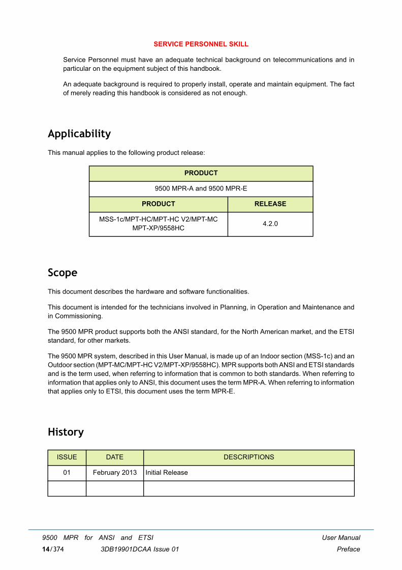
This manual applies to the following product release:
Scope
This document describes the hardware and software functionalities.
This document is intended for the technicians involved in Planning, in Operation and Maintenance andin Commissioning.
The 9500 MPR product supports both the ANSI standard, for the North American market, and the ETSIstandard, for other markets.
The 9500 MPR system, described in this User Manual, is made up of an Indoor section (MSS-1c) and anOutdoor section (MPT-MC/MPT-HC V2/MPT-XP/9558HC). MPR supports both ANSI and ETSI standardsand is the term used, when referring to information that is common to both standards. When referring toinformation that applies only to ANSI, this document uses the term MPR-A. When referring to informationthat applies only to ETSI, this document uses the term MPR-E.
History
PRODUCT
9500 MPR-A and 9500 MPR-E
PRODUCT RELEASE
MSS-1c/MPT-HC/MPT-HC V2/MPT-MCMPT-XP/9558HC 4.2.0
ISSUE DATE DESCRIPTIONS
01 February 2013 Initial Release
User Manual
Preface
9500 MPR for ANSI and ETSI
3DB19901DCAA Issue 01 15/374
Change notes
Handbook structure
This handbook has been edited according to the Alcatel-Lucent standardized �drawing-up guides"complying with such suggestion.
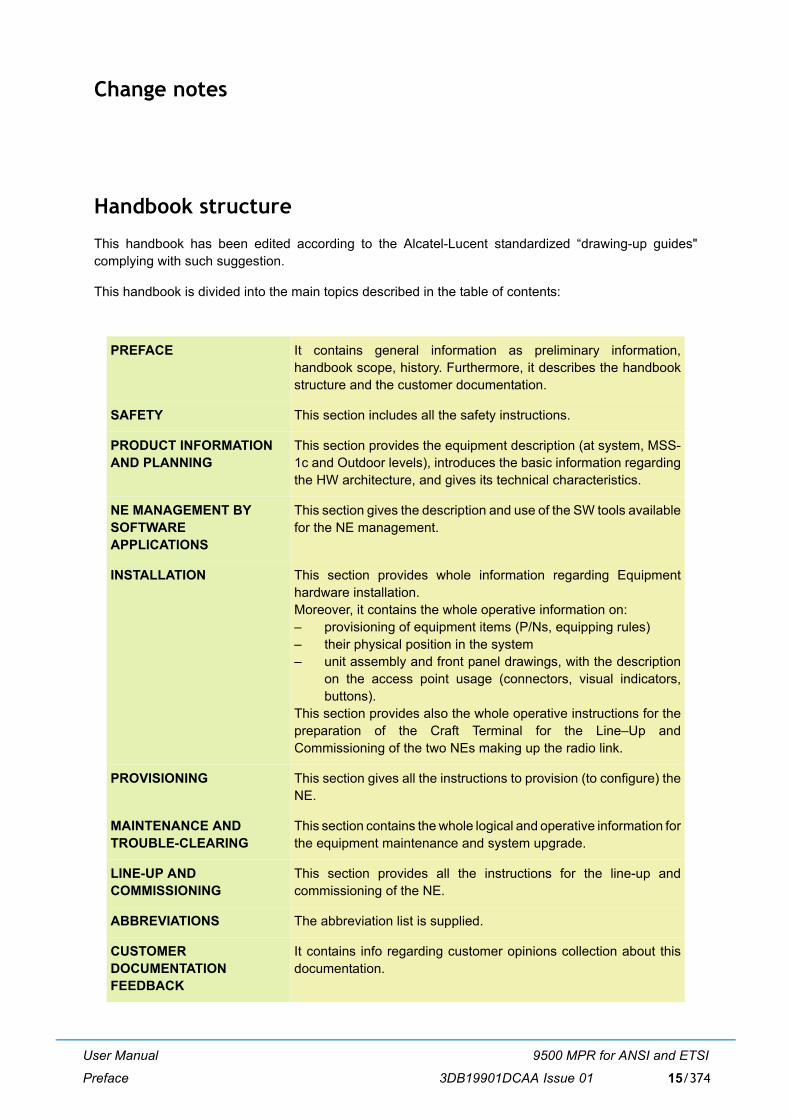
This handbook is divided into the main topics described in the table of contents:
PREFACE It contains general information as preliminary information,handbook scope, history. Furthermore, it describes the handbookstructure and the customer documentation.
SAFETY This section includes all the safety instructions.
PRODUCT INFORMATIONAND PLANNING
This section provides the equipment description (at system, MSS-1c and Outdoor levels), introduces the basic information regardingthe HW architecture, and gives its technical characteristics.
NE MANAGEMENT BYSOFTWAREAPPLICATIONS
This section gives the description and use of the SW tools availablefor the NE management.
INSTALLATION This section provides whole information regarding Equipmenthardware installation. Moreover, it contains the whole operative information on:� provisioning of equipment items (P/Ns, equipping rules)� their physical position in the system� unit assembly and front panel drawings, with the description
on the access point usage (connectors, visual indicators,buttons).
This section provides also the whole operative instructions for thepreparation of the Craft Terminal for the Line�Up andCommissioning of the two NEs making up the radio link.
PROVISIONING This section gives all the instructions to provision (to configure) theNE.
MAINTENANCE AND TROUBLE-CLEARING
This section contains the whole logical and operative information forthe equipment maintenance and system upgrade.
LINE-UP AND COMMISSIONING
This section provides all the instructions for the line-up andcommissioning of the NE.
ABBREVIATIONS The abbreviation list is supplied.
CUSTOMERDOCUMENTATIONFEEDBACK
It contains info regarding customer opinions collection about thisdocumentation.

User Manual
Preface
9500 MPR for ANSI and ETSI
3DB19901DCAA Issue 0116/374
General on Alcatel-Lucent customer documentation
This paragraph describes in general the Alcatel�Lucent Customer Documentation system, details theassociation between the product levels and the associated documentation, and explains CustomerDocumentation characteristics as well as the policies for its delivery and updating.
Customer�independent standard customer documentation
a) DefinitionStandard Customer Documentation, referred to hereafter, must be always meant as plant�independent and is always independent of any Customization.Plant�dependent and/or Customized documentation, if envisaged by the contract, is subjected tocommercial criteria as far as contents, formats and supply conditions are concerned.N.B. Plant�dependent and Customized documentation is not described here.
b) Aims of standard customer documentationStandard system, hardware and software documentation is meant to give the Customer personnelthe possibility and the information necessary for installing, commissioning, operating, andmaintaining the equipment according to Alcatel�Lucent Laboratory design and Installation Dept.choices. In particular:� the contents of the chapters associated to the software applications focus on the explanation
of the man�machine interface and of the operating procedures allowed by it;� maintenance is described down to faulty PCB location and replacement.N.B. No supply to Customers of design documentation (like PCB hardware design and productiondocuments and files, software source programs, programming tools, etc.) is envisaged.
Product levels and associated customer documentation
a) ProductsA �product� is defined by the network hierarchical level where it can be inserted and by the wholeof performances and services that it is meant for.E.g. 9500 MPR is a product.
b) Product-releasesA �product� evolves through successive �product�releases�, which are the real products marketedfor their delivery at a certain �product�release� availability date. A certain �product�release� performsmore functionalities than the previous one.E.g. Rel.1.0 and Rel.2.0 are two successive �product�releases� of the same �product�.A �product�release� comprehends a set of hardware components and at least one �SoftwarePackage� (SWP); as a whole, they identify the possible network applications and the equipmentperformances that the specific �product�release� has been designed, engineered, and marketed for.
c) Configurations and Network ElementsIn some cases, a �product�release� includes different possible �configurations� which aredistinguished from one another by different �Network Element� (NE) types and, from themanagement point of view, by different SWPs.
d) SWP releases, versions, and CD�ROMs� Each SWP is distributed by means of a specific SWP CD�ROM.� A SWP is identified by its �Denomination�, �P/N� (Part Number) and �CS� (Change Status), that
are printed on the CD�ROM�s label:� the first and second digits of the �Denomination� (e.g. 2.0) correspond to the �HW product�
release� number;� the third digit of the of the �Denomination� (e.g. 2.0.2) identifies the Version Level of the
SWP.

User Manual
Preface
9500 MPR for ANSI and ETSI
3DB19901DCAA Issue 01 17/374
� A SWP with new Version Level, providing main features in addition to those of the previousVersion Level SWP, is distributed by means of a SWP CD�ROM having new �Denomination�,�P/N� (Part Number), and �CS� restarting from 01
� A SWP patch version, if any, is created to correct SW bugs, and/or to add minor features, andis distributed by means of a SWP CD�ROM, that can be identified:� by the same �P/N� of the former CD�ROM, but with an incremented �CS� number
(e.g.CS=02 instead of previous CS=01)� or by a new �P/N�, and �CS� restarting from 01.
Handbook updating
The handbooks associated to the "product-release" are listed in �History� on page 14.
Each handbook is identified by: � the name of the "product�release" (and "version" when the handbook is applicable to the versions
starting from it, but not to the previous ones), � the handbook name, � the handbook Part Number, � the handbook edition (usually first edition=01),� the handbook issue date. The date on the handbook does not refer to the date of print but to the date
on which the handbook source file has been completed and released for the production.
Changes introduced in the same product�release (same handbook P/N)
The edition and date of issue might change on future handbook versions for the following reasons:
� only the date changes (pointed out in the Table of Contents) when modifications are made to theeditorial system not changing the technical contents of the handbook.
� the edition, hence the date, is changed because modifications made concern technical contents. Inthis case:
� the changes with respect to the previous edition are listed in �History� on page 14;� in affected chapters, revision bars on the left of the page indicate modifications in text and
drawings.
Changes concerning the technical contents of the handbook cause the edition number increase (e.g. fromEd.01 to Ed.02). Slight changes (e.g. for corrections) maintain the same edition but with the addition ofa version character (e.g. from Ed.02 to Ed.02A). Version character can be used for draft or proposaleditions.
NOTES FOR HANDBOOKS RELEVANT TO SOFTWARE APPLICATIONSHandbooks relevant to software applications (typically the Operator's Handbooks)are not modified unless the new software "version" distributed to Customersimplies man-machine interface changes or in case of slight modifications notaffecting the understanding of the explained procedures.
Moreover, should the screen prints included in the handbook contain the product�release's"version" marking, they are not replaced in the handbooks related to a subsequent version, ifthe screen contents are unchanged.
Supplying updated handbooks to customers
Supplying updated handbooks to customers who have already received previous issues is submitted tocommercial criteria.By updated handbook delivery it is meant the supply of a complete copy of the handbook new issue(supplying errata-corrige sheets is not envisaged).

User Manual
Preface
9500 MPR for ANSI and ETSI
3DB19901DCAA Issue 0118/374
Changes due to new product version
A new product version changes the handbook P/N and the edition starts from 01. In this case the modified parts of the handbook are not listed.

User Manual
FCC Part 15 subpart B
9500 MPR for ANSI and ETSI
3DB19901DCAA Issue 01 19/374
0 FCC Part 15 subpart B
0.1 9500 MPR-A unlicensed radio
The JF6-9558HC/6933B-9558HC (9558HC) unlicensed radio provides fast deployment of service withmicrowave radio. No license and small antennas (no FCC and Industry Canada requirements) allowimmediate turn-up. The 9558HC unlicensed radio can not be upgraded to licensed operation.
The JF6-9558HC/6933B-9558HC unlicensed radio operates in the 5725-5850 Information, Scientific, andMedical (ISM) band in accordance with FCC Part 15.247 and IC RSS-210. This unlicensed radio, althoughoperating in the same band as a spread spectrum radio, operates using narrower bandwidths than spreadspectrum.
Note: The 9558HC, 5.8 Unlicensed band JF6-9558HC/6933B-9558HC has been certified by the FCCand Industry Canada as of August 7, 2012.
0.2 FCC Class B compliance statement
The JF6-9558HC/6933B-9558HC unlicensed radio has been tested and found to comply with the limitsfor a Class B digital device, pursuant to Part 15 of the FCC Rules and IC RSS-210. These limits aredesigned to provide reasonable protection against harmful interference when the equipment is operatedin a commercial environment. This equipment generates, uses, and can radiate radio frequency energyand, if not installed and used in accordance with the instruction manual, may cause harmful interferenceto radio communications. Operation of this equipment in a residential area is likely to cause harmfulinterference in which case the user will be required to correct the interference at his own expense.
0.3 FCC Class B requirements
This device complies with part 15 of the FCC Rules and IC RSS-210. Operation is subject to the followingthree conditions: (1) this device may not cause harmful interference. (2) This device must accept anyinterference received, including interference that may cause undesired operation. (3) This device mustbe professionally installed.
Cet appareil radio est conforme à IC RSS-210. Son fonctionnement respecte les trois conditionssuivantes : 1) cette radio ne cause pas d�interférences néfastes, 2) cette radio peut recevoir desinterférences, ainsi que des interférences qui peuvent causer des opérations non désirées, et 3) cetteradio doit être installée par des Professionnels.
Note: Changes or modifications not expressly approved by Alcatel-Lucent could void the authority tooperate the JF6-9558HC/6933B-9558HC unlicensed radio.
Note: Installation, Turn-Up, Maintenance, and Operation Instruction supplied with the JF6-9558HC/6933B-9558HC unlicensed radio require strict adherence for continued part 15 of the FCCRules and IC RSS-210 compliance.
Note: Regulatory compliance warning: Physical changes or modifications to the JF6-9558H/6933B-9500MPT and JF6-9558HC/6933B-9558HC (unlicensed) radio are strictly prohibited.

User Manual
FCC Part 15 subpart B
9500 MPR for ANSI and ETSI
3DB19901DCAA Issue 0120/374

User Manual
Safety, EMC, EMF, ESD norms, equipment labeling,standards and compliance
9500 MPR for ANSI and ETSI
3DB19901DCAA Issue 01 21/374
1 Safety, EMC, EMF, ESD norms, equipmentlabeling, standards and compliance
This chapter describes the equipment labelling and the norms mandatory or suggested that must beconsidered to avoid injuries on persons and/or damage to the equipment.
This chapter is organized as follows:
� MPR-E: Declaration of conformity to CE marking and countries list
� Specific label for MPR equipment
� Applicable standards and recommendations
� Safety rules
� Electromagnetic compatibility (EMC norms)
� Equipment protection against electrostatic discharges
� Cautions to avoid equipment damage
� MPR-E: Waste from electrical and electronic equipment (WEEE)
� Standards and compliance

User Manual
Safety, EMC, EMF, ESD norms, equipment labeling,standards and compliance
9500 MPR for ANSI and ETSI
3DB19901DCAA Issue 0122/374
1.1 MPR-E: Declaration of conformity to CE marking and countries list
Indication of the countries where the equipment is intended to be used: Austria (AT) - Belgium (BE)- Bulgaria (BG) - Switzerland/Liechtenstein (CH) - Cyprus (CY) - Czech Republic (CZ) - Germany (DE)- Denmark (DK) - Estonia (EE) - Finland (FI) - France (FR) - Greece (GR) - Hungary (HU) � Italy (IT) -Ireland (IE) - Iceland (IS) - Lithuania (LT) � Luxembourg (LU) - Latvia (LV) - Malta (MT) - Netherlands (NL)- Norway (NO) �Poland (PL) � Portugal (PT) - Romania (RO) � Spain (SP) - Sweden (SE) - Slovenia (SI)- Slovak Republic (SK) -United Kingdom (UK)
Indication of the intended use of the equipment: Point to Point PDH/Ethernet Transport radio Link
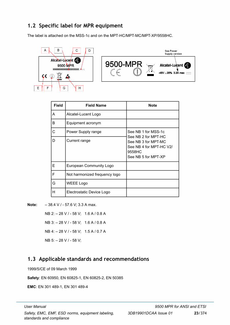
User Manual
Safety, EMC, EMF, ESD norms, equipment labeling,standards and compliance
9500 MPR for ANSI and ETSI
3DB19901DCAA Issue 01 23/374
1.2 Specific label for MPR equipment
The label is attached on the MSS-1c and on the MPT-HC/MPT-MC/MPT-XP/9558HC.
Note: � 38.4 V / - 57.6 V; 3.3 A max.
NB 2: � 28 V / - 58 V; 1.6 A / 0.8 A
NB 3: � 28 V / - 58 V; 1.6 A / 0.8 A
NB 4: � 28 V / - 58 V; 1.5 A / 0.7 A
NB 5: � 28 V / - 58 V;
1.3 Applicable standards and recommendations
1999/5/CE of 09 March 1999
Safety: EN 60950, EN 60825-1, EN 60825-2, EN 50385
EMC: EN 301 489-1, EN 301 489-4
Field Field Name Note
A Alcatel-Lucent Logo
B Equipment acronym
C Power Supply range See NB 1 for MSS-1cSee NB 2 for MPT-HCSee NB 3 for MPT-MCSee NB 4 for MPT-HC V2/9558HCSee NB 5 for MPT-XP
D Current range
E European Community Logo
F Not harmonized frequency logo
G WEEE Logo
H Electrostatic Device Logo

User Manual
Safety, EMC, EMF, ESD norms, equipment labeling,standards and compliance
9500 MPR for ANSI and ETSI
3DB19901DCAA Issue 0124/374
Spectrum: EN 302 217-2-2
1.4 Safety rules
Equipment intended for installation in Restricted Access Location
Equipment is only to be accessed by trained service personnel
1.4.1 General rules
Before carrying out any installation, turn-on, tests or operation and maintenance operations, read carefullythe related sections of this Manual, in particular:
� Hardware Installation
� Commissioning
� Maintenance and Upgrade
Observe safety rules
� When equipment is operating nobody is allowed to have access inside on the equipment parts whichare protected with Cover Plate Shields removable with tools.
� In case of absolute need to have access inside, on the equipment parts when it is operating this isallowed exclusively to service personnel, where for Service Personnel or Technical assistance ismeant:
� "personnel which has adequate Technical Knowledge and experience necessary to be awareof the danger that he might find in carrying out an operation and of the necessarymeasurements to reduce danger to minimum for him and for others".
� The Service Personnel can only replace the faulty units with spare parts.
� The Service Personnel is not allowed to repair: hence the access to the parts not specified isnot permitted.
� The keys and/or the tools used to open doors, hinged covers to remove parts which give accessto compartments in which are present high dangerous voltages must belong exclusively to theservice personnel.
� For the eventual cleaning of the external parts of the equipment, absolutely do not use anyinflammable substance or substances which in some way may alter the markings or inscriptions.
� It is recommended to use a slightly wet cleaning cloth.

User Manual
Safety, EMC, EMF, ESD norms, equipment labeling,standards and compliance
9500 MPR for ANSI and ETSI
3DB19901DCAA Issue 01 25/374
The Safety Rules stated in the handbook describe the operations and/or precautions to observe tosafeguard service personnel during the working phases and to guarantee equipment safety, i.e., notexposing persons, animals, things to the risk of being injured/damaged.
Whenever the safety protection features have been impaired, REMOVE POWER.
To cut off power proceed to switch off the power supply units as well as cut off power station upstream(rack or station distribution frame).
The safety rules described in this handbook are distinguished by the following symbol and statement:
1.4.2 Labels Indicating danger, forbiddance, command
It is of utmost importance to follow the instructions printed on the labels affixed to the units and assemblies.
� dangerous electrical voltages
� harmful optical signals
� risk of explosion
� moving mechanical parts
� heat-radiating Mechanical Parts
� microwave radiations
Pay attention to the information stated in the following, and proceed as instructed.
Note: The symbols presented in following paragraphs are all the possible symbols that could bepresent on Alcatel-Lucent equipment, but are not all necessarily present on the equipment thishandbook refers to.
Dangerous electrical voltages
[1] Labeling
The following warning label is affixed next to dangerous voltages (>42.4 Vp; >60 Vdc).
If it is a Class 1 equipment connected to mains, then the label associated to it will state that theequipment will have to be grounded before connecting it to the power supply voltage, e.g.:
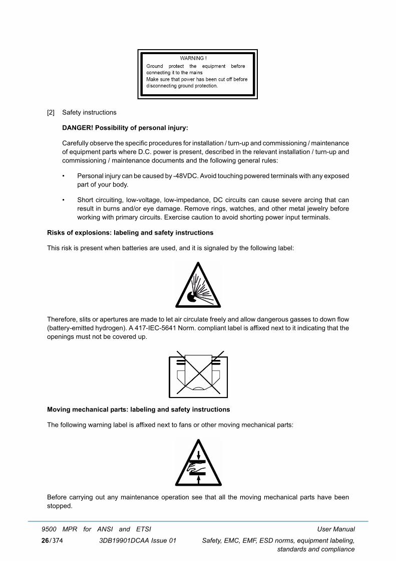
User Manual
Safety, EMC, EMF, ESD norms, equipment labeling,standards and compliance
9500 MPR for ANSI and ETSI
3DB19901DCAA Issue 0126/374
[2] Safety instructions
DANGER! Possibility of personal injury:
Carefully observe the specific procedures for installation / turn-up and commissioning / maintenanceof equipment parts where D.C. power is present, described in the relevant installation / turn-up andcommissioning / maintenance documents and the following general rules:
� Personal injury can be caused by -48VDC. Avoid touching powered terminals with any exposedpart of your body.
� Short circuiting, low-voltage, low-impedance, DC circuits can cause severe arcing that canresult in burns and/or eye damage. Remove rings, watches, and other metal jewelry beforeworking with primary circuits. Exercise caution to avoid shorting power input terminals.
Risks of explosions: labeling and safety instructions
This risk is present when batteries are used, and it is signaled by the following label:
Therefore, slits or apertures are made to let air circulate freely and allow dangerous gasses to down flow(battery-emitted hydrogen). A 417-IEC-5641 Norm. compliant label is affixed next to it indicating that theopenings must not be covered up.
Moving mechanical parts: labeling and safety instructions
The following warning label is affixed next to fans or other moving mechanical parts:
Before carrying out any maintenance operation see that all the moving mechanical parts have beenstopped.

User Manual
Safety, EMC, EMF, ESD norms, equipment labeling,standards and compliance
9500 MPR for ANSI and ETSI
3DB19901DCAA Issue 01 27/374
Equipment connection to earth
Terminals for equipment connection to earth, to be done according to international safety standards, arepointed out by the suitable symbol:
The position of earth connection terminals is specified in the Hardware Installation section.
Heat-radiating mechanical parts: labeling and safety instructions
The presence of heat-radiating mechanical parts is indicated by the following warning label in compliancywith IEC 417 Norm, Fig.5041:
DANGER! Possibility of personal injury:
Carefully observe the specific procedures for installation / turn-up and commissioning / maintenance ofequipment parts where heat-radiating mechanical parts are present, described in the relevant installation/ turn-up and commissioning / maintenance documents and the following general rule:
Personal injury can be caused by heat. Avoid touching powered terminals with any exposed part of yourbody.
Optical safety
The equipment contains Class 1 laser component according to IEC 60825-1 (par. 5).
The laser source is placed in the optional SFP plug-in, which has to be installed in the MSS-1c. The lasersource is placed in the left side of the SFP plug-in.
According to the IEC 60825-1 the explanatory label is not attached on the equipment due to the lack ofspace.
Microwave radiations (EMF norms)
Equipment emitting RF power (Reminder from site preparation procedure):
CLASS 1 LASER PRODUCT

User Manual
Safety, EMC, EMF, ESD norms, equipment labeling,standards and compliance
9500 MPR for ANSI and ETSI
3DB19901DCAA Issue 0128/374
The site must be compliant with ICNIRP guidelines or local regulation if more restrictive.
The following rules should be strictly applied by Customer:
� Non authorized persons should not enter the compliance boundaries, if any, for the general public.
� Compliance RF boundaries, if any, related to Electro Magnetic Field exposure must be marked.
� Workers should be allowed to switch-off the power if they have to operate inside complianceboundaries.
� Assure good cable connection.
� Install the antenna as high as possible from floor or area with public access (if possible the cylinderdelimiting the compliance boundaries, if any, or the cylinder corresponding to the transmission areadirectly in front of antenna with the same diameter as the antenna, more than 2 meters high).
� Install the antenna as far as possible from other existing equipment emitting RF power.
Anyway remind that someone standing in front of the 9500 MPR antenna may cause traffic shutdown.
Place the relevant stickers:
On the site when applicable (when people can cross the compliance boundaries and/or the transmissionarea of the antenna, i.e. roof top installation)
� Warning label "Do not stand on the antenna axis"
On the mast (front side)
� EMF emission warning sign (Yellow and black) to be placed at bottom of antenna, visible by someonemoving in front of the antenna (roof top installation)
On the antenna (rear side)
� EMF emission warning sign, placed on the antenna.
1.5 Electromagnetic compatibility (EMC norms)
The equipment's EMC norms depend on the type of installation being carried out, such as cabletermination and grounding, and on the operating conditions, such as equipment, setting options of theelectrical/electronic units, or presence of dummy covers.
Before carrying out any installation, turn-on, tests & operation and maintenance operations, read carefullythe related sections of this Manual, in particular:
� Hardware Installation
� Maintenance and Upgrade
EMF emission warning sign
User Manual
Safety, EMC, EMF, ESD norms, equipment labeling,standards and compliance
9500 MPR for ANSI and ETSI
3DB19901DCAA Issue 01 29/374
The norms set down to guarantee EMC compatibility, are distinguished inside this Manual by the symboland term:
[1] EMC General Norms - Installation
� All connections (towards the external source of the equipment) made with shielded cables useonly cables and connectors suggested in this Manual or in the relevant Plant Documentation,or those specified in the Customer's "Installation Norms" (or similar documents)
� Shielded cables must be suitably terminated
� Install filters outside the equipment as required
� Ground connect the equipment utilizing a conductor with proper diameter and impedance
� Mount shields (if utilized), previously positioned during the installation phase, but not beforehaving cleaned and degrease it
� Before inserting the shielded unit proceed to clean and degrease all peripheral surfaces(contact springs and connection points, etc.)
� Screw fasten the units to the subrack
� To correctly install EMC compatible equipment follow the instructions given
[2] EMC General Norms - Turn-on, Tests & Operation
� Preset the electrical units as required to guarantee EMC compatibility
� Check that the equipment is operating with all the shields properly positioned such as dummycovers and ESD connector protections
� To properly use EMC compatible equipment observe the information given
[3] EMC General Norms - Maintenance
� Before inserting the shielded unit, which will replace the faulty or modified unit, proceed to cleanand degrease all peripheral surfaces such as contact springs and connection points.
� Clean the dummy covers of the spare units
� Screw fasten the units to the subrack.
1.6 Equipment protection against electrostatic discharges
Before removing the ESD protections from the monitors, connectors etc., observe the precautionarymeasures stated. Make sure that the ESD protections have been replaced and after having terminatedthe maintenance and monitoring operations.
Most electronic devices are sensitive to electrostatic discharges, to this concern the following warninglabels have been affixed:
EMC Norms

User Manual
Safety, EMC, EMF, ESD norms, equipment labeling,standards and compliance
9500 MPR for ANSI and ETSI
3DB19901DCAA Issue 0130/374
Observe the precautionary measures stated when having to touch the electronic parts during theinstallation and maintenance phases.
Workers are supplied with anti static protection devices consisting of:
� an elasticized band worn around the wrist � a coiled cord connected to the elasticized band and to the stud on the subrack
1.7 Cautions to avoid equipment damage
a. Anti static protection device kit
Whenever is necessary to handle spare parts and cards out of their own box, this kit (Illustrationbelow) must be always warn and its termination must be connected to a grounded structure, to avoidthe possible damage of the electronic devices for electrostatic discharges.
Anti static protection device kit
b. Screw fixingIn normal operation conditions, all screws (for unit box closing, cable fixing, etc.) must be alwaystightened to avoid item detachment and to ensure the equipment EMI-EMC performance.The screw tightening torque must be:
2.8 kg x cm (0.28 Newton x m) ±10%2.4317 in lb (0.2026 ft lb) ±10%
Exceeding this value may result in screw breaking.
c. MSS-1c-ODU cable disconnection / connectionBefore to disconnect or connect the MSS-1c-ODU cable (at MSS-1c or ODU side) switch off thecorresponding MSS-1c Unit.
1.8 MPR-E: Waste from electrical and electronic equipment (WEEE)
This product must be selectively collected and treated. Treatment applied at end of life of the product shallcomply with the applicable national laws implementing directive on waste electrical and electronicequipment (WEEE).
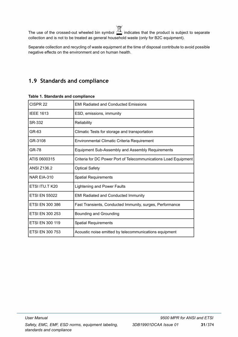
User Manual
Safety, EMC, EMF, ESD norms, equipment labeling,standards and compliance
9500 MPR for ANSI and ETSI
3DB19901DCAA Issue 01 31/374
The use of the crossed-out wheeled bin symbol indicates that the product is subject to separatecollection and is not to be treated as general household waste (only for B2C equipment).
Separate collection and recycling of waste equipment at the time of disposal contribute to avoid possiblenegative effects on the environment and on human health.
1.9 Standards and compliance
Table 1. Standards and compliance
CISPR 22 EMI Radiated and Conducted Emissions
IEEE 1613 ESD, emissions, immunity
SR-332 Reliability
GR-63 Climatic Tests for storage and transportation
GR-3108 Environmental Climatic Criteria Requirement
GR-78 Equipment Sub-Assembly and Assembly Requirements
ATIS 0600315 Criteria for DC Power Port of Telecommunications Load Equipment
ANSI Z136.2 Optical Safety
NAR EIA-310 Spatial Requirements
ETSI ITU.T K20 Lightening and Power Faults
ETSI EN 55022 EMI Radiated and Conducted Immunity
ETSI EN 300 386 Fast Transients, Conducted Immunity, surges, Performance
ETSI EN 300 253 Bounding and Grounding
ETSI EN 300 119 Spatial Requirements
ETSI EN 300 753 Acoustic noise emitted by telecommunications equipment

User Manual
Safety, EMC, EMF, ESD norms, equipment labeling,standards and compliance
9500 MPR for ANSI and ETSI
3DB19901DCAA Issue 0132/374
User Manual
Product information and planning
9500 MPR for ANSI and ETSI
3DB19901DCAA Issue 01 33/374
2 Product information and planningHere below the topics of this chapter are listed:
� 9500 family overview (par. 2.1 on page 34) � 9500 MPR system family (par. 2.1.1 on page 39) � Family elements described in this user manual (par. 2.1.2 on page 40) � MSS-1c (par. 2.1.3 on page 40)� MPT-HC (par. 2.1.4 on page 41)� MPT-HC V2/9558HC (par. 2.1.5 on page 41)� MPT-XP (par. 2.1.6 on page 42)� MPR-E: MPT-MC (par. 2.1.7 on page 43)� MSS-1c to MPT-HC interconnection (par. 2.1.8 on page 43)� MSS-1c to MPT-HC V2/9558HC interconnection (par. 2.1.9 on page 46)� MSS-1c to MPT-XP interconnection (par. 2.1.10 on page 48)� MSS-1c to MPT-MC interconnection (par. 2.1.11 on page 50)� Antennas (par. 2.1.12 on page 50)
� MPR-E: Radio capacity, channelling and modulation (MPT-HC/ MPT-HC V2/MPT-MC/MPT-XP)(par. 2.2 on page 51)
� Standard features (par. 2.4 on page 55)
� Radio configurations (par. 2.5 on page 56)
� Typical system configurations (par. 2.6 on page 57)
� Environmental and electrical characteristics (par. 2.7 on page 59)� General characteristics (MSS-1c) (par. 2.7.1 on page 59)� (par. on page 60)� MPR-E: MPT-MC characteristics (par. 2.7.3 on page 61)
� 6 to 13 GHz (par. 2.7.3.1 on page 61)� 15 to 38 GHz (par. 2.7.3.2 on page 62)
� MPR-E: MPT-HC/MPT-HC V2/MPT-XP characteristics (par. 2.7.4 on page 63)� MPT-HC/MPT-HC V2 5.8 to 13 GHz (par. 2.7.4.1 on page 63)� MPT-HC/MPT-HC V2 15 to 38 GHz (par. 2.7.4.2 on page 64)� MPT-XP 6 to 8 GHz (par. 2.7.4.3 on page 64)
� Radio performances (par. 2.7.6 on page 66) � MPR-E: General characteristics (power extractor) (par. 2.7.7 on page 66) � General characteristics (MPT Power Unit) (par. 2.7.8 on page 66) � General characteristics (MPT Extended Power Unit) (par. 2.7.10 on page 67)
� MPR-E: Parts lists (par. 2.8 on page 69)� MSS-1c (par. 2.8.1 on page 69) � MPT-HC/MPT-HC V2/MPT-XP optical interface option (par. 2.8.2 on page 69) � MPT-HC with internal diplexer (par. 2.8.3 on page 70) � MPT-HC with internal diplexer (par. 2.8.3 on page 70) � MPT-HC V2 with internal diplexer (par. 2.8.4 on page 73) � MPT-MC with internal diplexer (par. 2.8.5 on page 75)
User Manual
Product information and planning
9500 MPR for ANSI and ETSI
3DB19901DCAA Issue 0134/374
� MPT-HC/MPT-HC V2/MPT-MC/MPT-XP with external diplexer (par. 2.8.6 on page 76)
� MPR-A: parts lists (par. 2.9 on page 84)� MSS-1c (indoor unit) (par. 2.10.1 on page 88)
� External user interface (par. 2.10.1.1 on page 91)� Power supply (par. 2.10.1.2 on page 91)� Ethernet switch (par. 2.10.1.3 on page 91)� E1/T1 interface (par. 2.10.1.4 on page 91)� MPT interface (par. 2.10.1.5 on page 92)
� Fan unit (par. 2.10.2 on page 92)� MPT-HC (par. 2.10.3 on page 93)
� MPT-HC block diagram (par. 2.10.3.1 on page 95)� RSSI monitoring point (par. 2.10.3.2 on page 99)� Waveguide flange data (par. 2.10.3.3 on page 99)
� MPR-E: power extractor (par. 2.10.4 on page 100)� MPT-HC V2/MPT-XP/9558HC (par. 2.10.5 on page 100)� MPR-E: MPT-MC (par. 2.10.6 on page 101)� Radio transmission features with MPT-HC/MPT-HC V2/MPT-XP/ MPT-MC/9558HC (par.
2.10.9 on page 103)� Frequency agility (par. 2.10.9.1 on page 103)� Automatic transmit power control (ATPC) (par. 2.10.9.2 on page 103)� Transmitted power control: RTPC function (par. 2.10.9.3 on page 104)� Power monitoring (par. 2.10.9.4 on page 104)� Adaptive equalization (par. 2.10.9.5 on page 104)� Link identifier (par. 2.10.9.6 on page 104)� Loopbacks (par. 2.10.9.7 on page 104)� Loopback activation (par. 2.10.9.8 on page 105)� Loopback life time (par. 2.10.9.9 on page 105)� Unlicensed radio for 9558HC (par. 2.10.9.10 on page 106)
� TMN communication channels (par. 2.10.10 on page 108)� Traffic profiles (par. 2.10.11 on page 108)
� TDM2TDM (par. 2.10.11.1 on page 110)� TDM2Eth (par. 2.10.11.2 on page 111)� ETH2ETH (par. 2.10.11.3 on page 112)
� Ethernet traffic management (par. 2.10.12 on page 112)� Bridge type change (par. 2.10.12.1 on page 112)� Reserved multicast addresses (par. 2.10.12.2 on page 113)
� Quality of services (QoS) (par. 2.10.13 on page 114)� QoS in the MSS-1c (par. 2.10.13.1 on page 114)� QoS in the MPT (par. 2.10.13.2 on page 115)
� Cross-connections (par. 2.10.14 on page 117)� E1/T1 cross-connection (par. 2.10.14.1 on page 117)� Ethernet flows (par. 2.10.14.2 on page 118)
� Synchronization (par. 2.10.15 on page 118)� Synchronization overview (par. 2.10.15.1 on page 118)� Synchronization interface (par. 2.10.15.2 on page 120)
2.1 9500 family overview
9500MPR introduces the following elements to the microwave packet family:
� the most compact IDU solutions (MSS-1c) for E1 and Ethernet hybrid connectivity as well as witha zero footprint solution (no IDU) addressing full out-door applications;
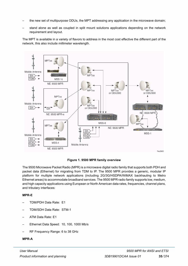
User Manual
Product information and planning
9500 MPR for ANSI and ETSI
3DB19901DCAA Issue 01 35/374
� the new set of multipurpose ODUs, the MPT addressing any application in the microwave domain;
� stand alone as well as coupled in split mount solutions applications depending on the networkrequirement and layout.
The MPT is available in a variety of flavors to address in the most cost effective the different part of thenetwork, this also include millimeter wavelength.
Figure 1. 9500 MPR family overview
The 9500 Microwave Packet Radio (MPR) is a microwave digital radio family that supports both PDH andpacket data (Ethernet) for migrating from TDM to IP. The 9500 MPR provides a generic, modular IPplatform for multiple network applications (including 2G/3G/HSDPA/WiMAX backhauling to MetroEthernet areas) to accommodate broadband services. The 9500 MPR radio family supports low, medium,and high capacity applications using European or North American data rates, frequencies, channel plans,and tributary interfaces:
MPR-E
� TDM/PDH Data Rate: E1
� TDM/SDH Data Rate: STM-1
� ATM Data Rate: E1
� Ethernet Data Speed: 10, 100, 1000 Mb/s
� RF Frequency Range: 6 to 38 GHz
MPR-A
User Manual
Product information and planning
9500 MPR for ANSI and ETSI
3DB19901DCAA Issue 0136/374
� TDM/PDH Data Rates: DS1, DS3
� TDM/SDH Data Rate: OC-3
� Ethernet Data Speed: 10, 100, 1000 Mb/s
� RF Frequency Range: 6 to 38 GHz
Four types of Indoor Units are available:
1) MSS-8, a 2U shelf, connected to an outdoor RF unit (split mount system). Supported ODUs:� ODU300� MPT-HC (MPR-E)/MPT-HC V2/ MPT-XP� MPT-MC (MPR-E)� 9558HC (MPR-A
2) MSS-4, one 1U shelf, connected to an outdoor RF unit (split mount system). Supported ODUs:� ODU300� MPT-HC (MPR-E)/MPT-HC V2/ MPT-XP� MPT-MC (MPR-E)� 9558HC (MPR-A)
3) MSS-1: a 1U shelf, connected to an outdoor RF unit (split-mount system)Supported ODUs:� MPT-HC V2/ MPT-XP� MPT-MC (MPR-E)
4) MSS-1c. Compact IDU that complements the existing portfolio addressing the last mile, the farend application in nodal solution and cost optimized point-to-point applications. Its small size of 1U height and half rack width drastically reduces the space consumption in busysites. Supported ODUs:� MPT-HC/MPT-HC V2/ MPT-XP� MPT-MC (MPR-E)� 9558HC (MPR-A
MPT is a multipurpose ODU to address any microwave application, extremely compact in size providing:
� MPT-MC (MPR-E): 155 Mbps max.
� MPT-HC/MPT-HC V2/ MPT-XP: 340 Mbps max.
MPT-xx can be deployed in stand-alone configuration (9500 MPR-e standalone) or it can be deployedin split mount solution connected to any MSS-x IDU.
� Up to 18 MPT connected to an MSS-8
� Up to 14 MPT connected to an MSS-4
� Up to 6 MPT units can be connected to an MSS-1
� 2 MPT-HC/MPT-HC V2/MPT-XP/MPT-MC/9558HC connected to MSS-1c

User Manual
Product information and planning
9500 MPR for ANSI and ETSI
3DB19901DCAA Issue 01 37/374
9500 MPR-e standalone is the stand alone, full outdoor application of the MPT xx to address full Ethernetsite backhauling (fixed or mobile) and to address converged MPLS metro networks reducing the numberof deployed equipment.
The 9500 MPR innovative solutions mainly are:
[1] Multiservice aggregation layer: the capacity to use Ethernet as a common transmission layer totransport any kind of traffic, independently by the type of interface. Ethernet becomes theconvergence layer.
[2] Service awareness: traffic handling and quality management, queuing traffic according to the typeof service assigned, independently by the type of interface.
[3] Packet node: no service aggregation limits with all traffic aggregated in packets, in term of: capacity,type of service requirements and type of interface.
[4] Service-driven adaptive modulation: fully exploit the air bandwidth in its entirety by changingmodulation scheme according to the propagation availability and allocate transport capacity,discriminating traffic by different services, only possible in a packet-based environment.
[1] Multiservice aggregation layer
Figure 2. Multiservice aggregation layer
9500 MPR aggregates and carries over a COMMON PACKET LAYER: TDM 2G, 3G, LTE and IP/Ethernet.This allows sharing of common packet transmission infrastructures, regardless of the nature of carriedtraffic.
Due to the nature of Ethernet, each service can be discriminated based on several parameters such asquality of service.
Mapping different access technologies over Ethernet is achieved by standardized protocols such as circuitemulation and pseudo-wire.
[2] Service awareness
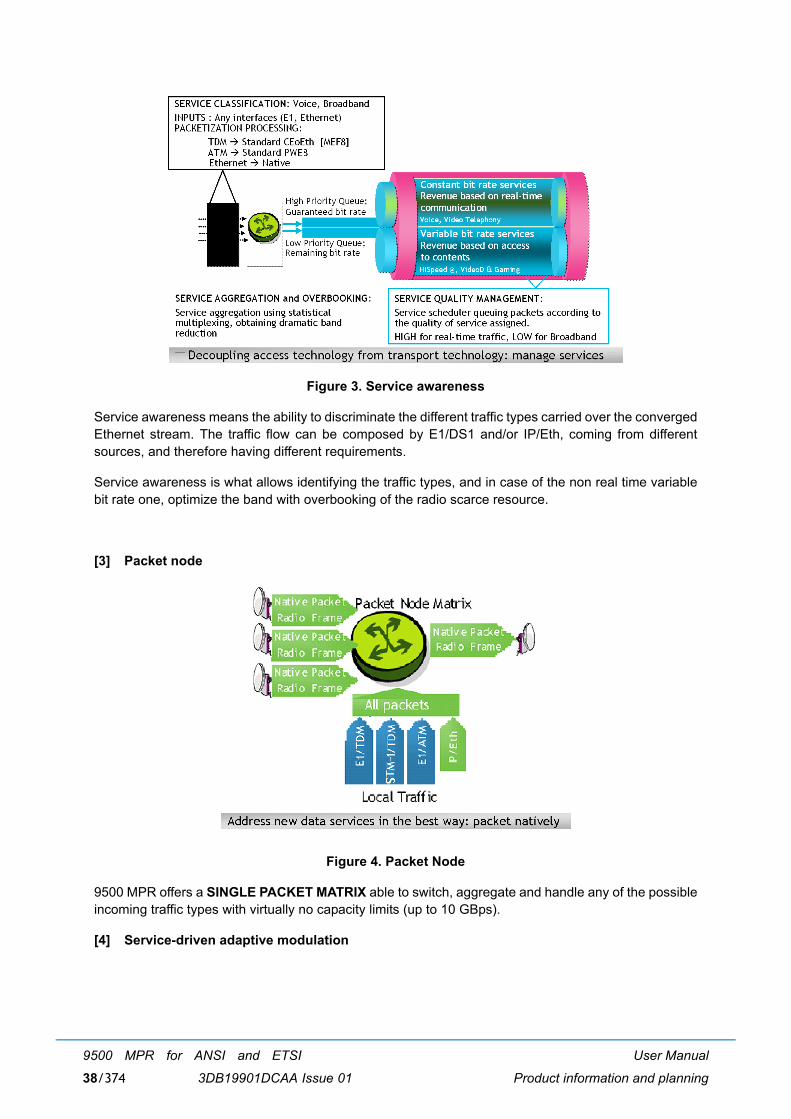
User Manual
Product information and planning
9500 MPR for ANSI and ETSI
3DB19901DCAA Issue 0138/374
Figure 3. Service awareness
Service awareness means the ability to discriminate the different traffic types carried over the convergedEthernet stream. The traffic flow can be composed by E1/DS1 and/or IP/Eth, coming from differentsources, and therefore having different requirements.
Service awareness is what allows identifying the traffic types, and in case of the non real time variablebit rate one, optimize the band with overbooking of the radio scarce resource.
[3] Packet node
Figure 4. Packet Node
9500 MPR offers a SINGLE PACKET MATRIX able to switch, aggregate and handle any of the possibleincoming traffic types with virtually no capacity limits (up to 10 GBps).
[4] Service-driven adaptive modulation
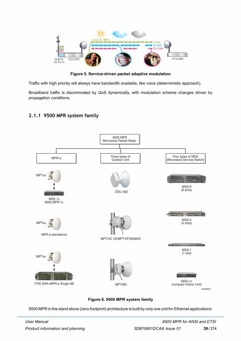
User Manual
Product information and planning
9500 MPR for ANSI and ETSI
3DB19901DCAA Issue 01 39/374
Figure 5. Service-driven packet adaptive modulation
Traffic with high priority will always have bandwidth available, like voice (deterministic approach).
Broadband traffic is discriminated by QoS dynamically, with modulation scheme changes driven bypropagation conditions.
2.1.1 9500 MPR system family
Figure 6. 9500 MPR system family
9500 MPR in the stand alone (zero-footprint) architecture is built by only one unit for Ethernet applications:
MSS-8(8 slots)
MSS-4(4 slots)
MSS-1(1 slot)
MSS-1c(compact InDoor Unit)
ODU 300
MPT-HC V2/MPT-XP/9558HC
MPT-MC
MSS 1c9500 MPR-1c
MPTxx
MPTxx
7705 SAR+MPR-e Single NE
MPR-e standalone
MPTxx
MPR-e Four types of MSS(Microwave Service Switch)
9500 MPRMicrowave Packet Radio
Three types ofOutdoor Unit
No2959

User Manual
Product information and planning
9500 MPR for ANSI and ETSI
3DB19901DCAA Issue 0140/374
� Outdoor Unit.
� The Outdoor Unit is connected to the MPLS metro networks equipment with one electrical Ethernetcable for data and power supply, or with one coaxial cable for the power supply and one opticalEthernet cable for the data (with MPT).
9500 MPR in the split mount architecture is built by two separate units:
� MSS (Microwave Service Switch): indoor unit for split mount and stand alone configurations(Ethernet uplink)
� Outdoor Unit.
2.1.2 Family elements described in this user manual
In this User Manual the MPR-1c access solution with the MSS-1c and MPT-HC/MPT-HC V2/MPT-XP/MPT-MC (MPR-E) /9558HC (MPR-A) is described:
The implemented radio configuration is 1+0.
The MSS-1c can collect up to 10 or 16 TDM flows and Ethernet flows.
The MSS-1c interfaces the Outdoor Unit (MPT-HC or MPT-HC V2 or MPT-MC (MPR-E) or MPT-XP oror 9558HC (MPR-A) thanks to its Ethernet interface.
MPT-HC or MPT-HC V2 or MPT-MC (MPR-E) or MPT-XP or 9558HC (MPR-A) is in a charge oftransporting the flows in an efficient way (bandwidth optimization, Quality of service, respect to TDMconstraints...).
2.1.3 MSS-1c
The MSS-1c provides user port interface, cross-connection and switching management.
The cross-connection matrix implements all the cross-connections between the User ports (4 Ethernetports and E1/T1 streams) and the Radio port. The matrix is a standard Ethernet switch, based on VLAN,assigned by the MCT.
The E1/T1 enter the LIU and then the IWF, which manages the encapsulation and reconstruction of PDHdata to and from standard Ethernet packets and sends and receives standard Ethernet packets to andfrom the Ethernet switch.
Two variants of MSS-1c are available:
� MSS-1c providing 10E1 and 4 User ethernet ports
� MSS-1c 16PDH providing 16E1 or 16T1 and 4 User Ethernet ports. This version is HW ready tomanage up to 2 STM-1 frames (instead of 2 Ethernet ports) not supported by the current SW Release
The Radio Interface interfaces the MPT-HC or MPT-HC V2 or the MPT-MC (MPR-E) or MPT-XP or9558HC (MPR-A).
The radio interface is a standard GbEth interface: electrical only for MPT-MC (MPR-E) and electrical oroptical for MPT-HC, MPT-HC V2, MPT-XP and 9558HC (MPR-A). It sends/receives standard Ethernetpackets to/from the Ethernet switch.
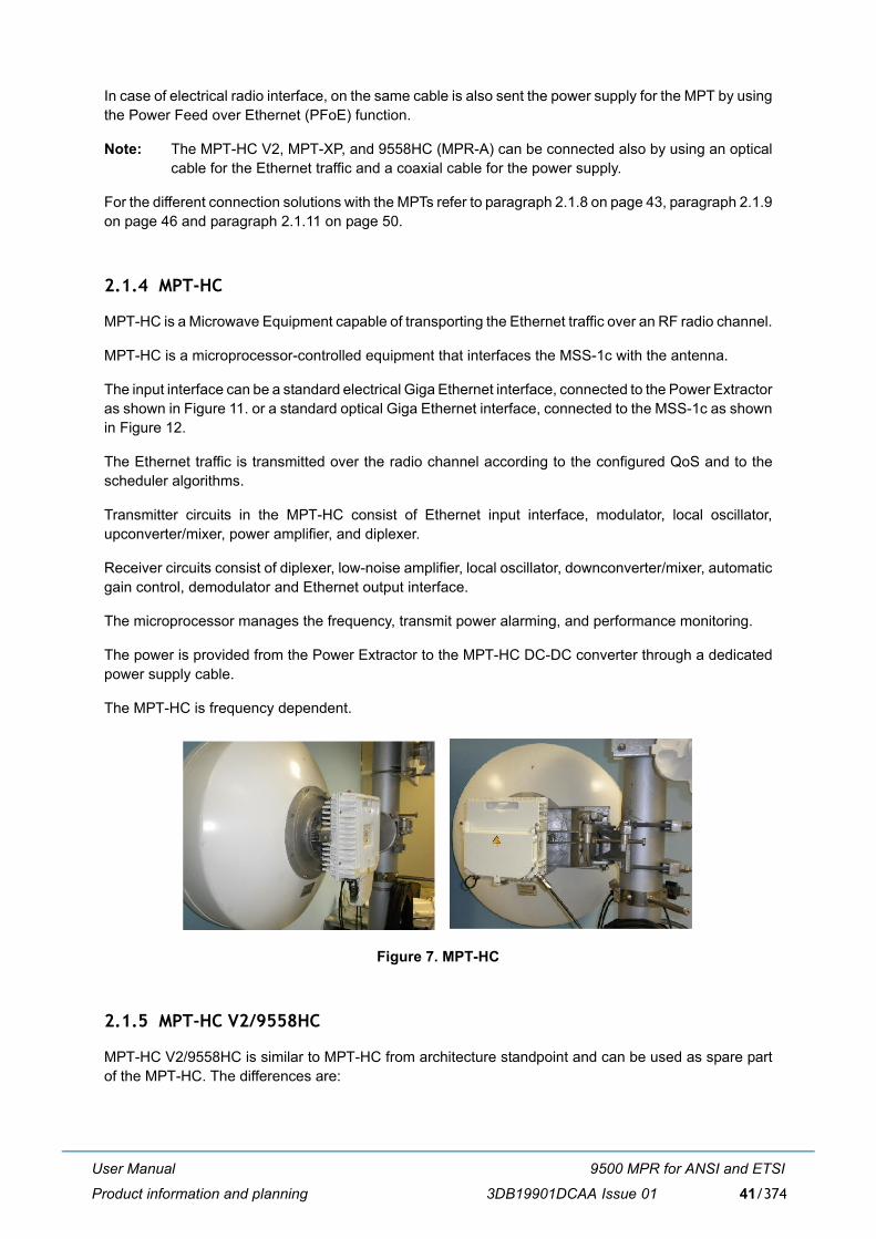
User Manual
Product information and planning
9500 MPR for ANSI and ETSI
3DB19901DCAA Issue 01 41/374
In case of electrical radio interface, on the same cable is also sent the power supply for the MPT by usingthe Power Feed over Ethernet (PFoE) function.
Note: The MPT-HC V2, MPT-XP, and 9558HC (MPR-A) can be connected also by using an opticalcable for the Ethernet traffic and a coaxial cable for the power supply.
For the different connection solutions with the MPTs refer to paragraph 2.1.8 on page 43, paragraph 2.1.9on page 46 and paragraph 2.1.11 on page 50.
2.1.4 MPT-HC
MPT-HC is a Microwave Equipment capable of transporting the Ethernet traffic over an RF radio channel.
MPT-HC is a microprocessor-controlled equipment that interfaces the MSS-1c with the antenna.
The input interface can be a standard electrical Giga Ethernet interface, connected to the Power Extractoras shown in Figure 11. or a standard optical Giga Ethernet interface, connected to the MSS-1c as shownin Figure 12.
The Ethernet traffic is transmitted over the radio channel according to the configured QoS and to thescheduler algorithms.
Transmitter circuits in the MPT-HC consist of Ethernet input interface, modulator, local oscillator,upconverter/mixer, power amplifier, and diplexer.
Receiver circuits consist of diplexer, low-noise amplifier, local oscillator, downconverter/mixer, automaticgain control, demodulator and Ethernet output interface.
The microprocessor manages the frequency, transmit power alarming, and performance monitoring.
The power is provided from the Power Extractor to the MPT-HC DC-DC converter through a dedicatedpower supply cable.
The MPT-HC is frequency dependent.
Figure 7. MPT-HC
2.1.5 MPT-HC V2/9558HC
MPT-HC V2/9558HC is similar to MPT-HC from architecture standpoint and can be used as spare partof the MPT-HC. The differences are:
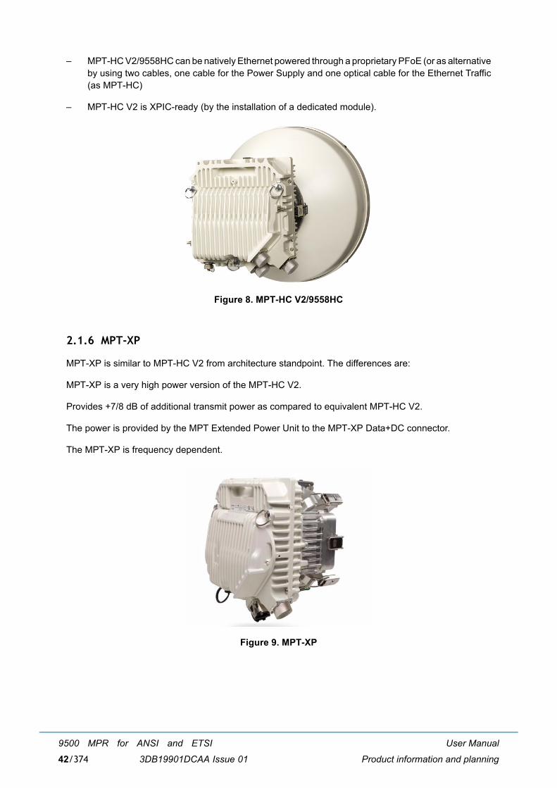
User Manual
Product information and planning
9500 MPR for ANSI and ETSI
3DB19901DCAA Issue 0142/374
� MPT-HC V2/9558HC can be natively Ethernet powered through a proprietary PFoE (or as alternativeby using two cables, one cable for the Power Supply and one optical cable for the Ethernet Traffic(as MPT-HC)
� MPT-HC V2 is XPIC-ready (by the installation of a dedicated module).
Figure 8. MPT-HC V2/9558HC
2.1.6 MPT-XP
MPT-XP is similar to MPT-HC V2 from architecture standpoint. The differences are:
MPT-XP is a very high power version of the MPT-HC V2.
Provides +7/8 dB of additional transmit power as compared to equivalent MPT-HC V2.
The power is provided by the MPT Extended Power Unit to the MPT-XP Data+DC connector.
The MPT-XP is frequency dependent.
Figure 9. MPT-XP
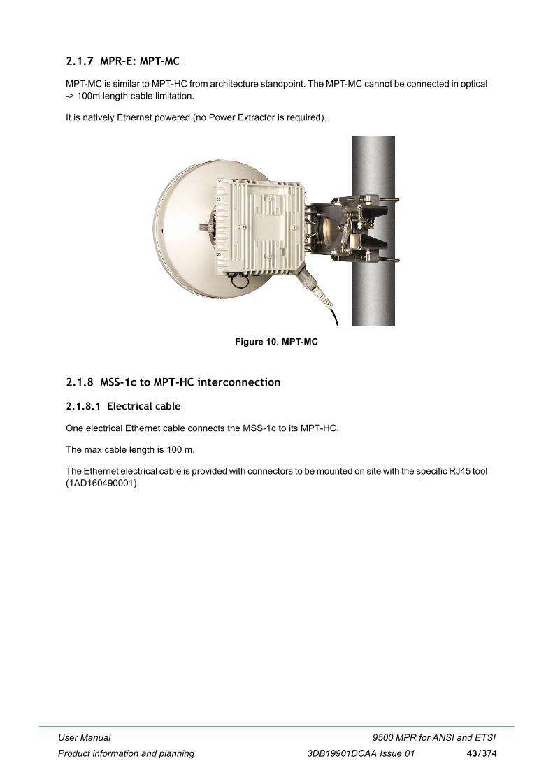
User Manual
Product information and planning
9500 MPR for ANSI and ETSI
3DB19901DCAA Issue 01 43/374
2.1.7 MPR-E: MPT-MC
MPT-MC is similar to MPT-HC from architecture standpoint. The MPT-MC cannot be connected in optical-> 100m length cable limitation.
It is natively Ethernet powered (no Power Extractor is required).
Figure 10. MPT-MC
2.1.8 MSS-1c to MPT-HC interconnection
2.1.8.1 Electrical cable
One electrical Ethernet cable connects the MSS-1c to its MPT-HC.
The max cable length is 100 m.
The Ethernet electrical cable is provided with connectors to be mounted on site with the specific RJ45 tool(1AD160490001).
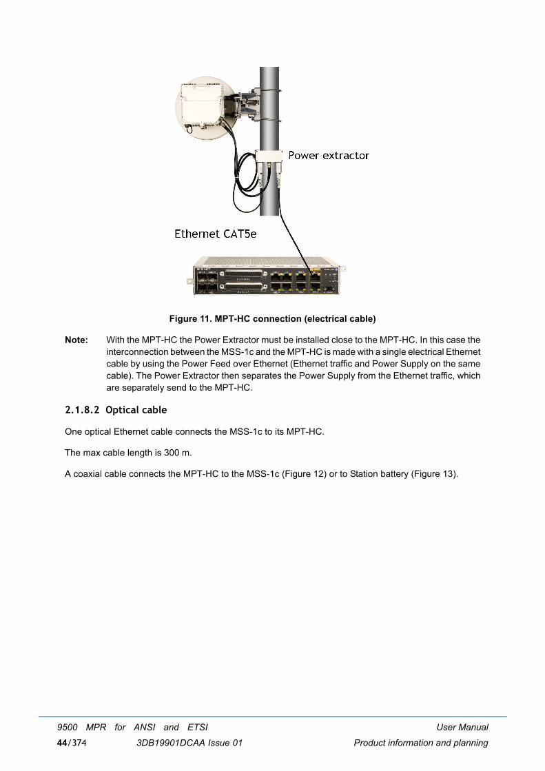
User Manual
Product information and planning
9500 MPR for ANSI and ETSI
3DB19901DCAA Issue 0144/374
Figure 11. MPT-HC connection (electrical cable)
Note: With the MPT-HC the Power Extractor must be installed close to the MPT-HC. In this case theinterconnection between the MSS-1c and the MPT-HC is made with a single electrical Ethernetcable by using the Power Feed over Ethernet (Ethernet traffic and Power Supply on the samecable). The Power Extractor then separates the Power Supply from the Ethernet traffic, whichare separately send to the MPT-HC.
2.1.8.2 Optical cable
One optical Ethernet cable connects the MSS-1c to its MPT-HC.
The max cable length is 300 m.
A coaxial cable connects the MPT-HC to the MSS-1c (Figure 12) or to Station battery (Figure 13).
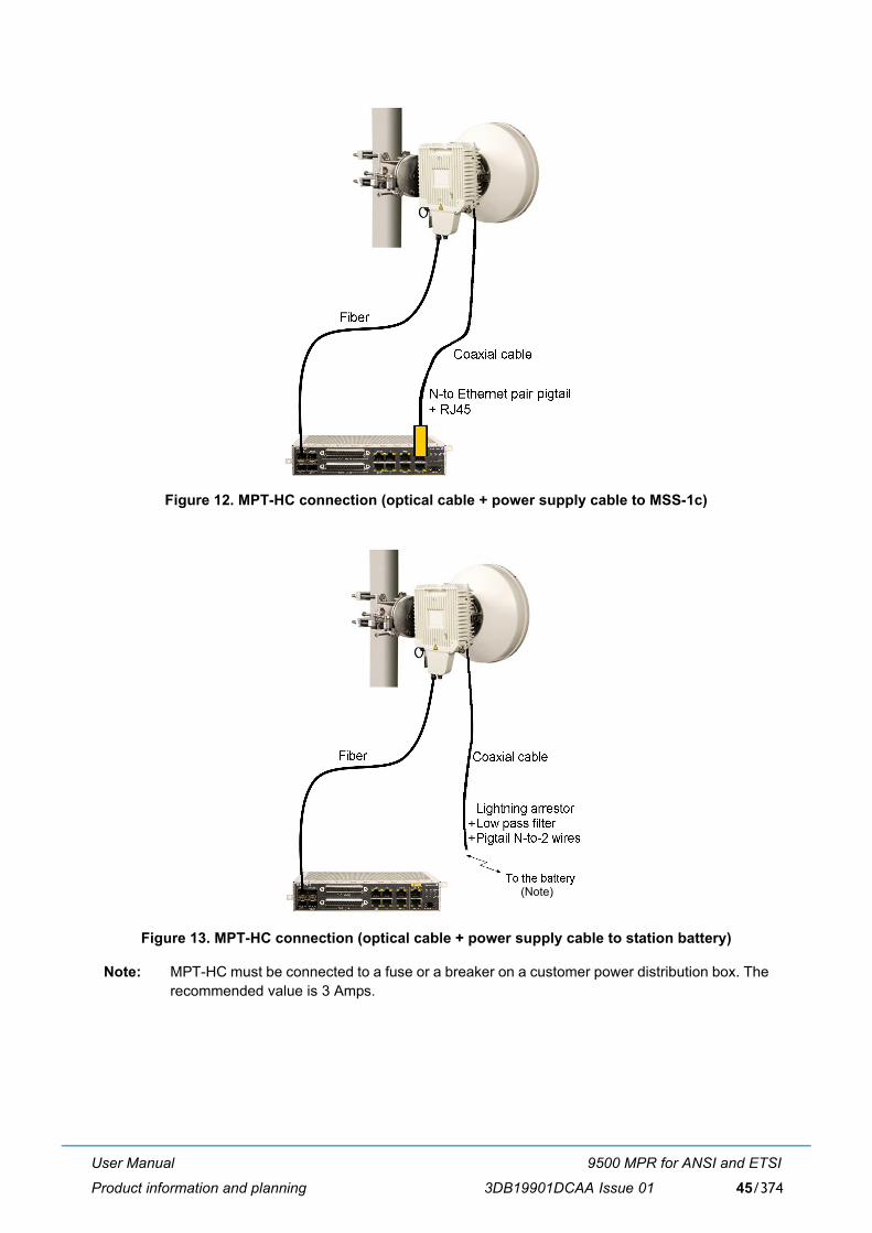
User Manual
Product information and planning
9500 MPR for ANSI and ETSI
3DB19901DCAA Issue 01 45/374
Figure 12. MPT-HC connection (optical cable + power supply cable to MSS-1c)
Figure 13. MPT-HC connection (optical cable + power supply cable to station battery)
Note: MPT-HC must be connected to a fuse or a breaker on a customer power distribution box. Therecommended value is 3 Amps.
(Note)
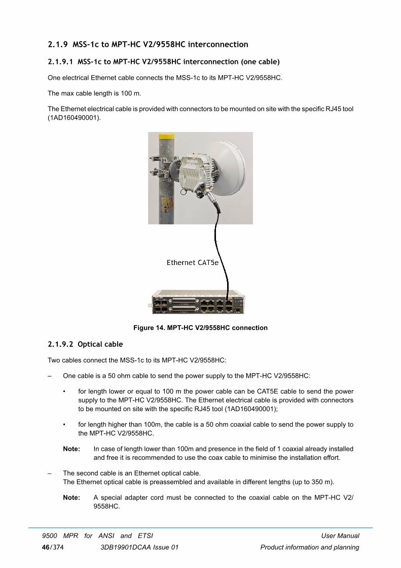
User Manual
Product information and planning
9500 MPR for ANSI and ETSI
3DB19901DCAA Issue 0146/374
2.1.9 MSS-1c to MPT-HC V2/9558HC interconnection
2.1.9.1 MSS-1c to MPT-HC V2/9558HC interconnection (one cable)
One electrical Ethernet cable connects the MSS-1c to its MPT-HC V2/9558HC.
The max cable length is 100 m.
The Ethernet electrical cable is provided with connectors to be mounted on site with the specific RJ45 tool(1AD160490001).
Figure 14. MPT-HC V2/9558HC connection
2.1.9.2 Optical cable
Two cables connect the MSS-1c to its MPT-HC V2/9558HC:
� One cable is a 50 ohm cable to send the power supply to the MPT-HC V2/9558HC:
� for length lower or equal to 100 m the power cable can be CAT5E cable to send the powersupply to the MPT-HC V2/9558HC. The Ethernet electrical cable is provided with connectorsto be mounted on site with the specific RJ45 tool (1AD160490001);
� for length higher than 100m, the cable is a 50 ohm coaxial cable to send the power supply tothe MPT-HC V2/9558HC.
Note: In case of length lower than 100m and presence in the field of 1 coaxial already installedand free it is recommended to use the coax cable to minimise the installation effort.
� The second cable is an Ethernet optical cable.The Ethernet optical cable is preassembled and available in different lengths (up to 350 m).
Note: A special adapter cord must be connected to the coaxial cable on the MPT-HC V2/9558HC.
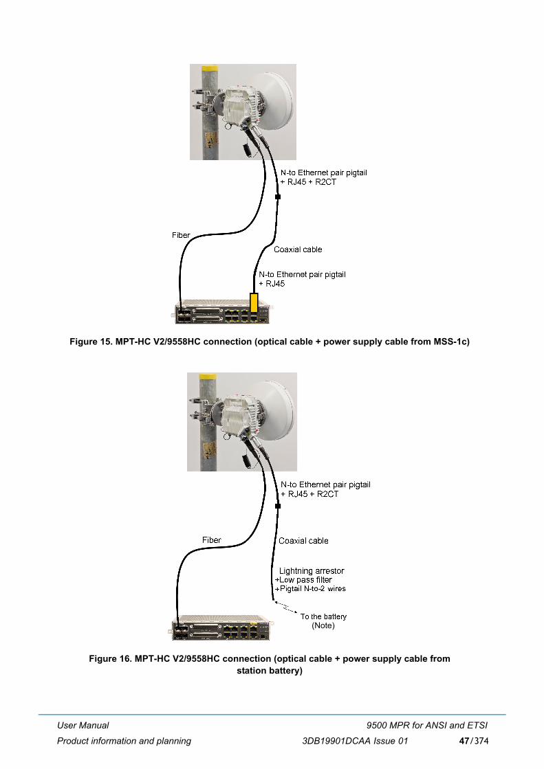
User Manual
Product information and planning
9500 MPR for ANSI and ETSI
3DB19901DCAA Issue 01 47/374
Figure 15. MPT-HC V2/9558HC connection (optical cable + power supply cable from MSS-1c)
Figure 16. MPT-HC V2/9558HC connection (optical cable + power supply cable fromstation battery)
(Note)
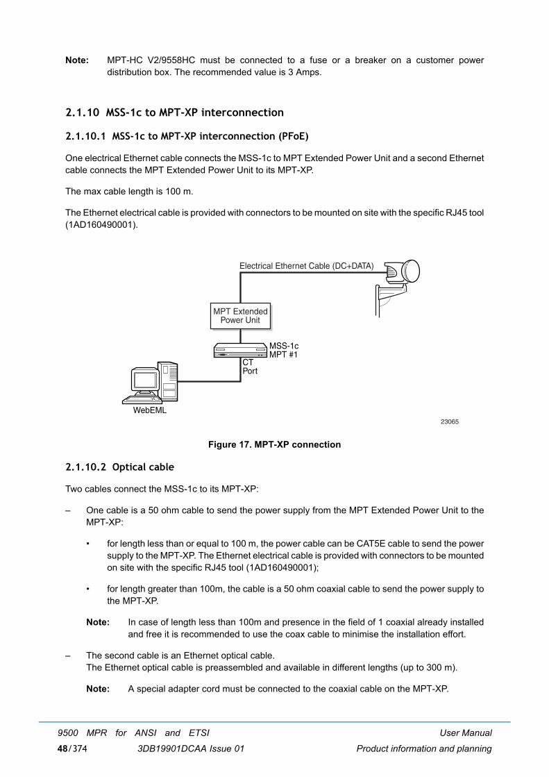
User Manual
Product information and planning
9500 MPR for ANSI and ETSI
3DB19901DCAA Issue 0148/374
Note: MPT-HC V2/9558HC must be connected to a fuse or a breaker on a customer powerdistribution box. The recommended value is 3 Amps.
2.1.10 MSS-1c to MPT-XP interconnection
2.1.10.1 MSS-1c to MPT-XP interconnection (PFoE)
One electrical Ethernet cable connects the MSS-1c to MPT Extended Power Unit and a second Ethernetcable connects the MPT Extended Power Unit to its MPT-XP.
The max cable length is 100 m.
The Ethernet electrical cable is provided with connectors to be mounted on site with the specific RJ45 tool(1AD160490001).
Figure 17. MPT-XP connection
2.1.10.2 Optical cable
Two cables connect the MSS-1c to its MPT-XP:
� One cable is a 50 ohm cable to send the power supply from the MPT Extended Power Unit to theMPT-XP:
� for length less than or equal to 100 m, the power cable can be CAT5E cable to send the powersupply to the MPT-XP. The Ethernet electrical cable is provided with connectors to be mountedon site with the specific RJ45 tool (1AD160490001);
� for length greater than 100m, the cable is a 50 ohm coaxial cable to send the power supply tothe MPT-XP.
Note: In case of length less than 100m and presence in the field of 1 coaxial already installedand free it is recommended to use the coax cable to minimise the installation effort.
� The second cable is an Ethernet optical cable.The Ethernet optical cable is preassembled and available in different lengths (up to 300 m).
Note: A special adapter cord must be connected to the coaxial cable on the MPT-XP.
MPT ExtendedPower Unit
MSS-1cMPT #1
CTPort
WebEML
Electrical Ethernet Cable (DC+DATA)
23065
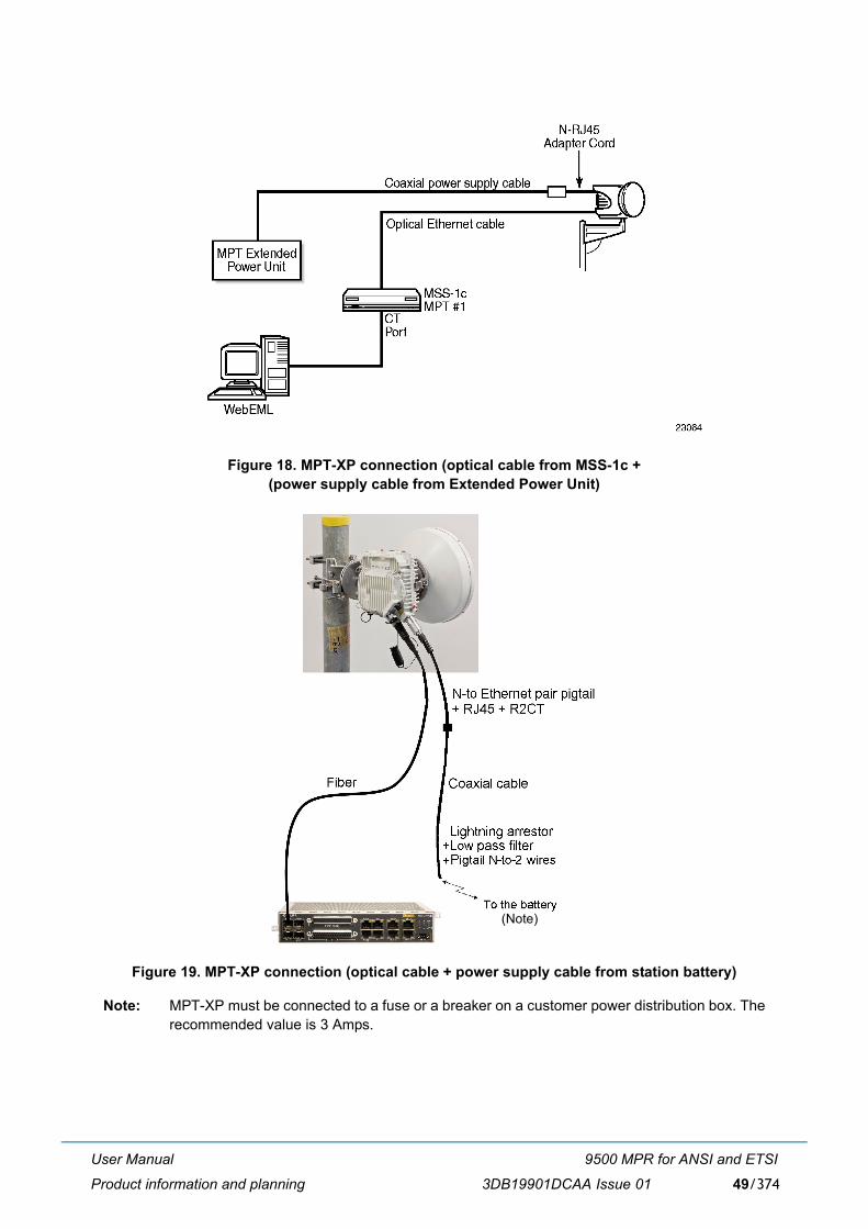
User Manual
Product information and planning
9500 MPR for ANSI and ETSI
3DB19901DCAA Issue 01 49/374
Figure 18. MPT-XP connection (optical cable from MSS-1c + (power supply cable from Extended Power Unit)
Figure 19. MPT-XP connection (optical cable + power supply cable from station battery)
Note: MPT-XP must be connected to a fuse or a breaker on a customer power distribution box. Therecommended value is 3 Amps.
(Note)
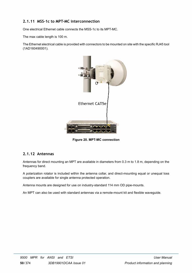
User Manual
Product information and planning
9500 MPR for ANSI and ETSI
3DB19901DCAA Issue 0150/374
2.1.11 MSS-1c to MPT-MC interconnection
One electrical Ethernet cable connects the MSS-1c to its MPT-MC.
The max cable length is 100 m.
The Ethernet electrical cable is provided with connectors to be mounted on site with the specific RJ45 tool(1AD160490001).
Figure 20. MPT-MC connection
2.1.12 Antennas
Antennas for direct mounting an MPT are available in diameters from 0.3 m to 1.8 m, depending on thefrequency band.
A polarization rotator is included within the antenna collar, and direct-mounting equal or unequal losscouplers are available for single antenna protected operation.
Antenna mounts are designed for use on industry-standard 114 mm OD pipe-mounts.
An MPT can also be used with standard antennas via a remote-mount kit and flexible waveguide.
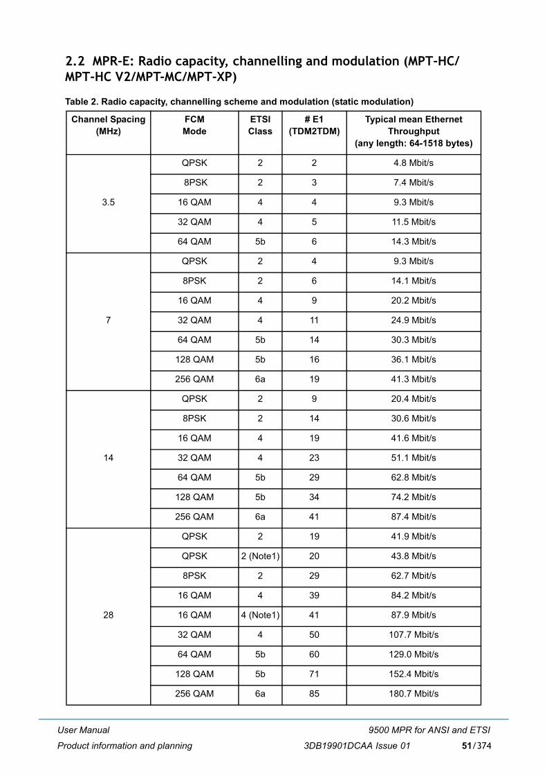
User Manual
Product information and planning
9500 MPR for ANSI and ETSI
3DB19901DCAA Issue 01 51/374
2.2 MPR-E: Radio capacity, channelling and modulation (MPT-HC/MPT-HC V2/MPT-MC/MPT-XP)
Table 2. Radio capacity, channelling scheme and modulation (static modulation)
Channel Spacing(MHz)
FCM Mode
ETSI Class
# E1(TDM2TDM)
Typical mean Ethernet Throughput
(any length: 64-1518 bytes)
3.5
QPSK 2 2 4.8 Mbit/s
8PSK 2 3 7.4 Mbit/s
16 QAM 4 4 9.3 Mbit/s
32 QAM 4 5 11.5 Mbit/s
64 QAM 5b 6 14.3 Mbit/s
7
QPSK 2 4 9.3 Mbit/s
8PSK 2 6 14.1 Mbit/s
16 QAM 4 9 20.2 Mbit/s
32 QAM 4 11 24.9 Mbit/s
64 QAM 5b 14 30.3 Mbit/s
128 QAM 5b 16 36.1 Mbit/s
256 QAM 6a 19 41.3 Mbit/s
14
QPSK 2 9 20.4 Mbit/s
8PSK 2 14 30.6 Mbit/s
16 QAM 4 19 41.6 Mbit/s
32 QAM 4 23 51.1 Mbit/s
64 QAM 5b 29 62.8 Mbit/s
128 QAM 5b 34 74.2 Mbit/s
256 QAM 6a 41 87.4 Mbit/s
28
QPSK 2 19 41.9 Mbit/s
QPSK 2 (Note1) 20 43.8 Mbit/s
8PSK 2 29 62.7 Mbit/s
16 QAM 4 39 84.2 Mbit/s
16 QAM 4 (Note1) 41 87.9 Mbit/s
32 QAM 4 50 107.7 Mbit/s
64 QAM 5b 60 129.0 Mbit/s
128 QAM 5b 71 152.4 Mbit/s
256 QAM 6a 85 180.7 Mbit/s
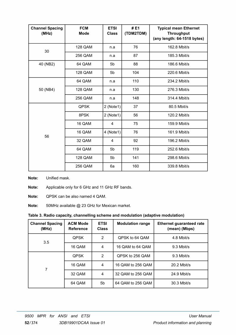
User Manual
Product information and planning
9500 MPR for ANSI and ETSI
3DB19901DCAA Issue 0152/374
Note: Unified mask.
Note: Applicable only for 6 GHz and 11 GHz RF bands.
Note: QPSK can be also named 4 QAM.
Note: 50MHz available @ 23 GHz for Mexican market.
Table 3. Radio capacity, channelling scheme and modulation (adaptive modulation)
30128 QAM n.a 76 162.8 Mbit/s
256 QAM n.a 87 185.3 Mbit/s
40 (NB2) 64 QAM 5b 88 186.6 Mbit/s
128 QAM 5b 104 220.6 Mbit/s
50 (NB4)
64 QAM n.a 110 234.2 Mbit/s
128 QAM n.a 130 276.3 Mbit/s
256 QAM n.a 148 314.4 Mbit/s
56
QPSK 2 (Note1) 37 80.5 Mbit/s
8PSK 2 (Note1) 56 120.2 Mbit/s
16 QAM 4 75 159.9 Mbit/s
16 QAM 4 (Note1) 76 161.9 Mbit/s
32 QAM 4 92 196.2 Mbit/s
64 QAM 5b 119 252.6 Mbit/s
128 QAM 5b 141 298.6 Mbit/s
256 QAM 6a 160 339.8 Mbit/s
Channel Spacing(MHz)
ACM ModeReference
ETSI Class
Modulation range Ethernet guaranteed rate(mean) (Mbps)
3.5QPSK 2 QPSK to 64 QAM 4.8 Mbit/s
16 QAM 4 16 QAM to 64 QAM 9.3 Mbit/s
7
QPSK 2 QPSK to 256 QAM 9.3 Mbit/s
16 QAM 4 16 QAM to 256 QAM 20.2 Mbit/s
32 QAM 4 32 QAM to 256 QAM 24.9 Mbit/s
64 QAM 5b 64 QAM to 256 QAM 30.3 Mbit/s
Channel Spacing(MHz)
FCM Mode
ETSI Class
# E1(TDM2TDM)
Typical mean Ethernet Throughput
(any length: 64-1518 bytes)
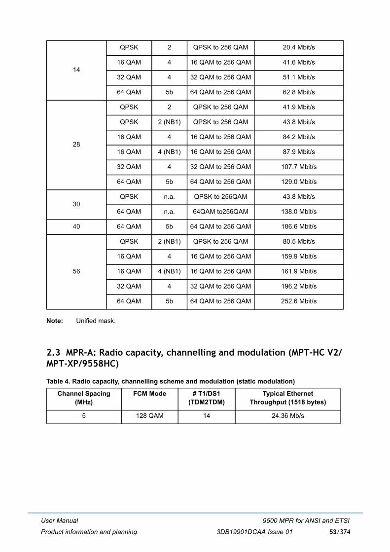
User Manual
Product information and planning
9500 MPR for ANSI and ETSI
3DB19901DCAA Issue 01 53/374
Note: Unified mask.
2.3 MPR-A: Radio capacity, channelling and modulation (MPT-HC V2/MPT-XP/9558HC)
Table 4. Radio capacity, channelling scheme and modulation (static modulation)
14
QPSK 2 QPSK to 256 QAM 20.4 Mbit/s
16 QAM 4 16 QAM to 256 QAM 41.6 Mbit/s
32 QAM 4 32 QAM to 256 QAM 51.1 Mbit/s
64 QAM 5b 64 QAM to 256 QAM 62.8 Mbit/s
28
QPSK 2 QPSK to 256 QAM 41.9 Mbit/s
QPSK 2 (NB1) QPSK to 256 QAM 43.8 Mbit/s
16 QAM 4 16 QAM to 256 QAM 84.2 Mbit/s
16 QAM 4 (NB1) 16 QAM to 256 QAM 87.9 Mbit/s
32 QAM 4 32 QAM to 256 QAM 107.7 Mbit/s
64 QAM 5b 64 QAM to 256 QAM 129.0 Mbit/s
30QPSK n.a. QPSK to 256QAM 43.8 Mbit/s
64 QAM n.a. 64QAM to256QAM 138.0 Mbit/s
40 64 QAM 5b 64 QAM to 256 QAM 186.6 Mbit/s
56
QPSK 2 (NB1) QPSK to 256 QAM 80.5 Mbit/s
16 QAM 4 16 QAM to 256 QAM 159.9 Mbit/s
16 QAM 4 (NB1) 16 QAM to 256 QAM 161.9 Mbit/s
32 QAM 4 32 QAM to 256 QAM 196.2 Mbit/s
64 QAM 5b 64 QAM to 256 QAM 252.6 Mbit/s
Channel Spacing(MHz)
FCM Mode # T1/DS1(TDM2TDM)
Typical Ethernet Throughput (1518 bytes)
5 128 QAM 14 24.36 Mb/s
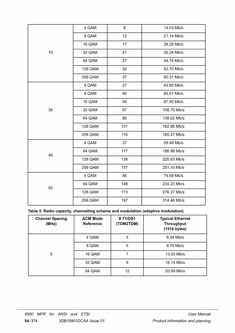
User Manual
Product information and planning
9500 MPR for ANSI and ETSI
3DB19901DCAA Issue 0154/374
Table 5. Radio capacity, channelling scheme and modulation (adaptive modulation)
10
4 QAM 8 14.03 Mb/s
8 QAM 12 21.14 Mb/s
16 QAM 17 28.28 Mb/s
32 QAM 21 35.24 Mb/s
64 QAM 27 44.74 Mb/s
128 QAM 32 52.70 Mb/s
256 QAM 37 60.31 Mb/s
30
4 QAM 27 43.85 Mb/s
8 QAM 40 65.51 Mb/s
16 QAM 54 87.45 Mb/s
32 QAM 67 108.75 Mb/s
64 QAM 86 138.02 Mb/s
128 QAM 101 162.88 Mb/s
256 QAM 116 185.37 Mb/s
40
4 QAM 37 59.48 Mb/s
64 QAM 117 186.98 Mb/s
128 QAM 138 220.63 Mb/s
256 QAM 157 251.10 Mb/s
50
4 QAM 46 74.59 Mb/s
64 QAM 146 234.23 Mb/s
128 QAM 173 276.37 Mb/s
256 QAM 197 314.46 Mb/s
Channel Spacing(MHz)
ACM ModeReference
# T1/DS1(TDM2TDM)
Typical EthernetThroughput(1518 bytes)
5
4 QAM 3 6.34 Mb/s
8 QAM 5 9.70 Mb/s
16 QAM 7 13.03 Mb/s
32 QAM 9 16.14 Mb/s
64 QAM 12 20.59 Mb/s
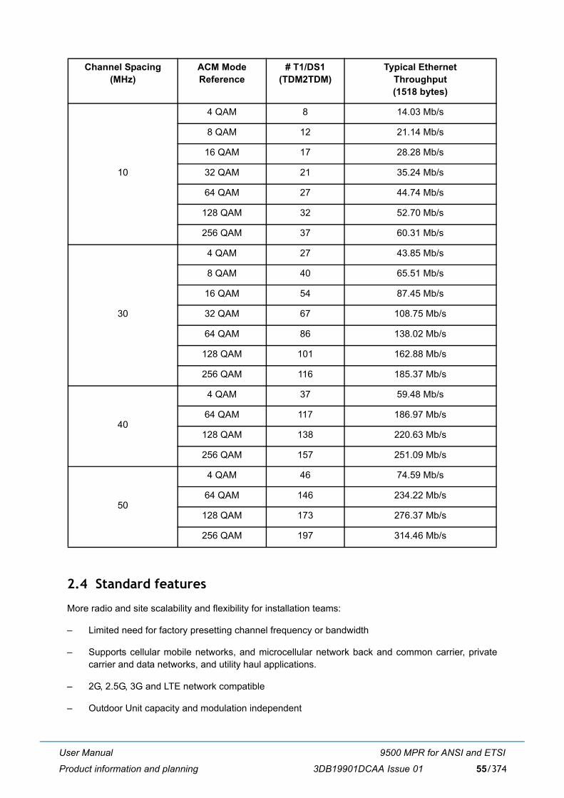
User Manual
Product information and planning
9500 MPR for ANSI and ETSI
3DB19901DCAA Issue 01 55/374
2.4 Standard features
More radio and site scalability and flexibility for installation teams:
� Limited need for factory presetting channel frequency or bandwidth
� Supports cellular mobile networks, and microcellular network back and common carrier, privatecarrier and data networks, and utility haul applications.
� 2G, 2.5G, 3G and LTE network compatible
� Outdoor Unit capacity and modulation independent
10
4 QAM 8 14.03 Mb/s
8 QAM 12 21.14 Mb/s
16 QAM 17 28.28 Mb/s
32 QAM 21 35.24 Mb/s
64 QAM 27 44.74 Mb/s
128 QAM 32 52.70 Mb/s
256 QAM 37 60.31 Mb/s
30
4 QAM 27 43.85 Mb/s
8 QAM 40 65.51 Mb/s
16 QAM 54 87.45 Mb/s
32 QAM 67 108.75 Mb/s
64 QAM 86 138.02 Mb/s
128 QAM 101 162.88 Mb/s
256 QAM 116 185.37 Mb/s
40
4 QAM 37 59.48 Mb/s
64 QAM 117 186.97 Mb/s
128 QAM 138 220.63 Mb/s
256 QAM 157 251.09 Mb/s
50
4 QAM 46 74.59 Mb/s
64 QAM 146 234.22 Mb/s
128 QAM 173 276.37 Mb/s
256 QAM 197 314.46 Mb/s
Channel Spacing(MHz)
ACM ModeReference
# T1/DS1(TDM2TDM)
Typical EthernetThroughput(1518 bytes)
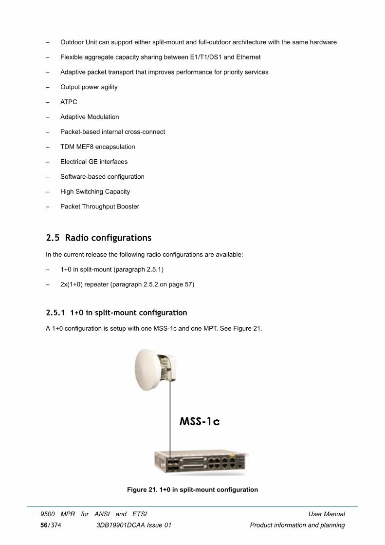
User Manual
Product information and planning
9500 MPR for ANSI and ETSI
3DB19901DCAA Issue 0156/374
� Outdoor Unit can support either split-mount and full-outdoor architecture with the same hardware
� Flexible aggregate capacity sharing between E1/T1/DS1 and Ethernet
� Adaptive packet transport that improves performance for priority services
� Output power agility
� ATPC
� Adaptive Modulation
� Packet-based internal cross-connect
� TDM MEF8 encapsulation
� Electrical GE interfaces
� Software-based configuration
� High Switching Capacity
� Packet Throughput Booster
2.5 Radio configurations
In the current release the following radio configurations are available:
� 1+0 in split-mount (paragraph 2.5.1)
� 2x(1+0) repeater (paragraph 2.5.2 on page 57)
2.5.1 1+0 in split-mount configuration
A 1+0 configuration is setup with one MSS-1c and one MPT. See Figure 21.
Figure 21. 1+0 in split-mount configuration
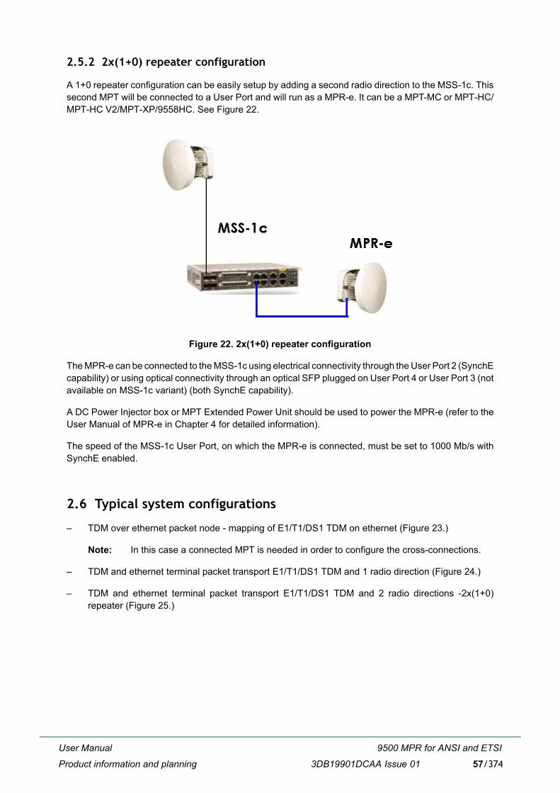
User Manual
Product information and planning
9500 MPR for ANSI and ETSI
3DB19901DCAA Issue 01 57/374
2.5.2 2x(1+0) repeater configuration
A 1+0 repeater configuration can be easily setup by adding a second radio direction to the MSS-1c. Thissecond MPT will be connected to a User Port and will run as a MPR-e. It can be a MPT-MC or MPT-HC/MPT-HC V2/MPT-XP/9558HC. See Figure 22.
Figure 22. 2x(1+0) repeater configuration
The MPR-e can be connected to the MSS-1c using electrical connectivity through the User Port 2 (SynchEcapability) or using optical connectivity through an optical SFP plugged on User Port 4 or User Port 3 (notavailable on MSS-1c variant) (both SynchE capability).
A DC Power Injector box or MPT Extended Power Unit should be used to power the MPR-e (refer to theUser Manual of MPR-e in Chapter 4 for detailed information).
The speed of the MSS-1c User Port, on which the MPR-e is connected, must be set to 1000 Mb/s withSynchE enabled.
2.6 Typical system configurations
� TDM over ethernet packet node - mapping of E1/T1/DS1 TDM on ethernet (Figure 23.)
Note: In this case a connected MPT is needed in order to configure the cross-connections.
� TDM and ethernet terminal packet transport E1/T1/DS1 TDM and 1 radio direction (Figure 24.)
� TDM and ethernet terminal packet transport E1/T1/DS1 TDM and 2 radio directions -2x(1+0)repeater (Figure 25.)
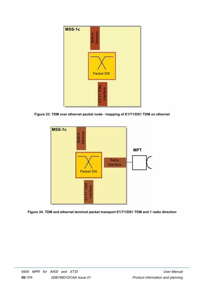
User Manual
Product information and planning
9500 MPR for ANSI and ETSI
3DB19901DCAA Issue 0158/374
Figure 23. TDM over ethernet packet node - mapping of E1/T1/DS1 TDM on ethernet
Figure 24. TDM and ethernet terminal packet transport E1/T1/DS1 TDM and 1 radio direction
MSS-1c
Packet SW
E1/
T1 T
DM
Inte
rface
Bui
lt-in
Eth
erne
t
MSS-1c
Packet SW
E1/
T1 T
DM
Inte
rface
Bui
lt-in
Eth
erne
t
RadioInterface
MPT
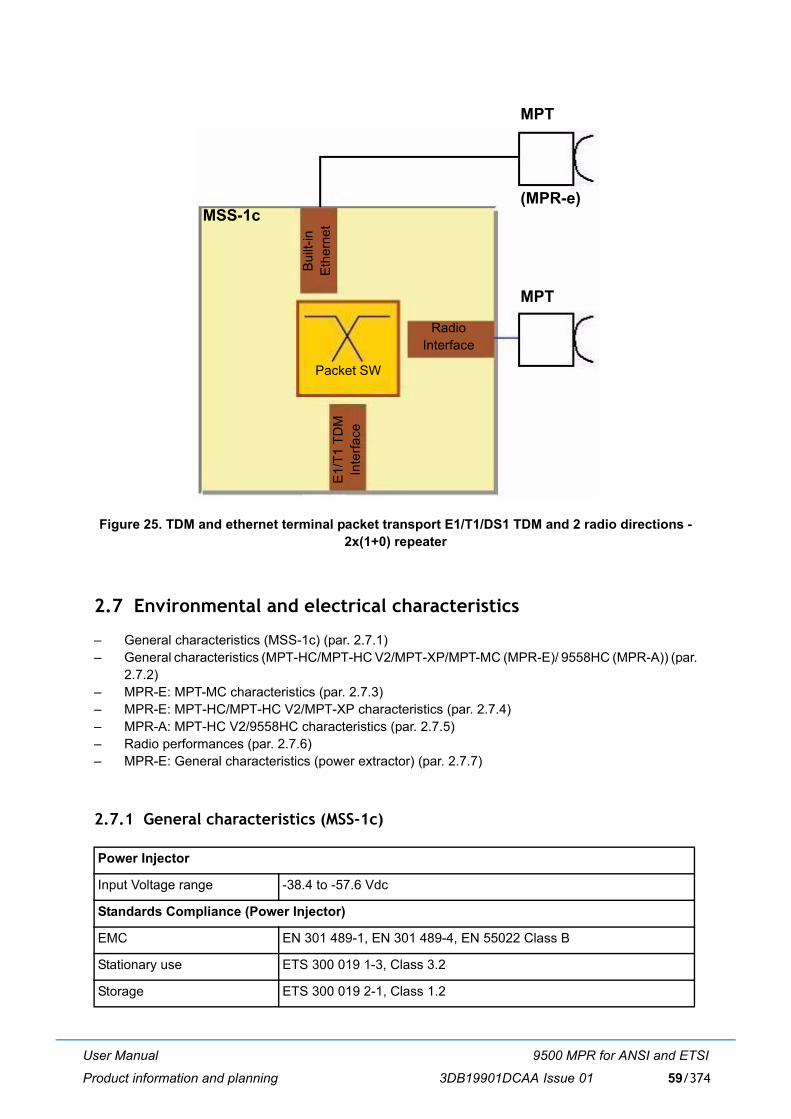
User Manual
Product information and planning
9500 MPR for ANSI and ETSI
3DB19901DCAA Issue 01 59/374
Figure 25. TDM and ethernet terminal packet transport E1/T1/DS1 TDM and 2 radio directions -2x(1+0) repeater
2.7 Environmental and electrical characteristics
� General characteristics (MSS-1c) (par. 2.7.1)� General characteristics (MPT-HC/MPT-HC V2/MPT-XP/MPT-MC (MPR-E)/ 9558HC (MPR-A)) (par.
2.7.2)� MPR-E: MPT-MC characteristics (par. 2.7.3)� MPR-E: MPT-HC/MPT-HC V2/MPT-XP characteristics (par. 2.7.4)� MPR-A: MPT-HC V2/9558HC characteristics (par. 2.7.5)� Radio performances (par. 2.7.6)� MPR-E: General characteristics (power extractor) (par. 2.7.7)
2.7.1 General characteristics (MSS-1c)
Power Injector
Input Voltage range -38.4 to -57.6 Vdc
Standards Compliance (Power Injector)
EMC EN 301 489-1, EN 301 489-4, EN 55022 Class B
Stationary use ETS 300 019 1-3, Class 3.2
Storage ETS 300 019 2-1, Class 1.2
MSS-1c
Packet SW
E1/
T1 T
DM
Inte
rface
Bui
lt-in
Eth
erne
tRadio
Interface
MPT
MPT
(MPR-e)
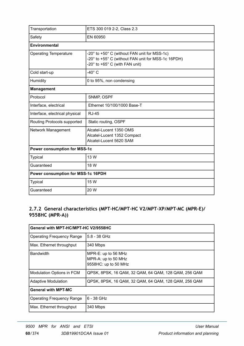
User Manual
Product information and planning
9500 MPR for ANSI and ETSI
3DB19901DCAA Issue 0160/374
2.7.2 General characteristics (MPT-HC/MPT-HC V2/MPT-XP/MPT-MC (MPR-E)/9558HC (MPR-A))
Transportation ETS 300 019 2-2, Class 2.3
Safety EN 60950
Environmental
Operating Temperature -20° to +50° C (without FAN unit for MSS-1c)-20° to +55° C (without FAN unit for MSS-1c 16PDH)-20° to +65° C (with FAN unit)
Cold start-up -40° C
Humidity 0 to 95%, non condensing
Management
Protocol SNMP, OSPF
Interface, electrical Ethernet 10/100/1000 Base-T
Interface, electrical physical RJ-45
Routing Protocols supported Static routing, OSPF
Network Management Alcatel-Lucent 1350 OMSAlcatel-Lucent 1352 CompactAlcatel-Lucent 5620 SAM
Power consumption for MSS-1c
Typical 13 W
Guaranteed 18 W
Power consumption for MSS-1c 16PDH
Typical 15 W
Guaranteed 20 W
General with MPT-HC/MPT-HC V2/9558HC
Operating Frequency Range 5.8 - 38 GHz
Max. Ethernet throughput 340 Mbps
Bandwidth MPR-E: up to 56 MHzMPR-A: up to 50 MHz9558HC: up to 50 MHz
Modulation Options in FCM QPSK, 8PSK, 16 QAM, 32 QAM, 64 QAM, 128 QAM, 256 QAM
Adaptive Modulation QPSK, 8PSK, 16 QAM, 32 QAM, 64 QAM, 128 QAM, 256 QAM
General with MPT-MC
Operating Frequency Range 6 - 38 GHz
Max. Ethernet throughput 340 Mbps
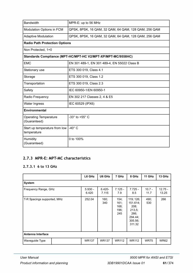
User Manual
Product information and planning
9500 MPR for ANSI and ETSI
3DB19901DCAA Issue 01 61/374
2.7.3 MPR-E: MPT-MC characteristics
2.7.3.1 6 to 13 GHz
Bandwidth MPR-E: up to 56 MHz
Modulation Options in FCM QPSK, 8PSK, 16 QAM, 32 QAM, 64 QAM, 128 QAM, 256 QAM
Adaptive Modulation QPSK, 8PSK, 16 QAM, 32 QAM, 64 QAM, 128 QAM, 256 QAM
Radio Path Protection Options
Non Protected, 1+0
Standards Compliance (MPT-HC/MPT-HC V2/MPT-XP/MPT-MC/9558HC)
EMC EN 301 489-1, EN 301 489-4, EN 55022 Class B
Stationary use ETS 300 019, Class 4.1
Storage ETS 300 019, Class 1.2
Transportation ETS 300 019, Class 2.3
Safety IEC 60950-1/EN 60950-1
Radio Frequency EN 302 217 Classes 2, 4 & E5
Water Ingress IEC 60529 (IPX6)
Environmental
Operating Temperature(Guaranteed)
-33° to +55° C
Start up temperature from lowtemperature
-40° C
Humidity(Guaranteed)
0 to 100%
L6 GHz U6 GHz 7 GHz 8 GHz 11 GHz 13 GHz
System
Frequency Range, GHz 5.930 - 6.420
6.420-7.115
7.125 - 7.9
7.725 - 8.5
10.7 - 11.7
12.75 - 13.25
T-R Spacings supported, MHz 252.04 160; 340
154;161;168;196;245
119; 126; 151.614;
208; 213,5; 266;
294.44; 305.56; 311.32
490; 530
266
Antenna Interface
Waveguide Type WR137 WR137 WR112 WR112 WR75 WR62
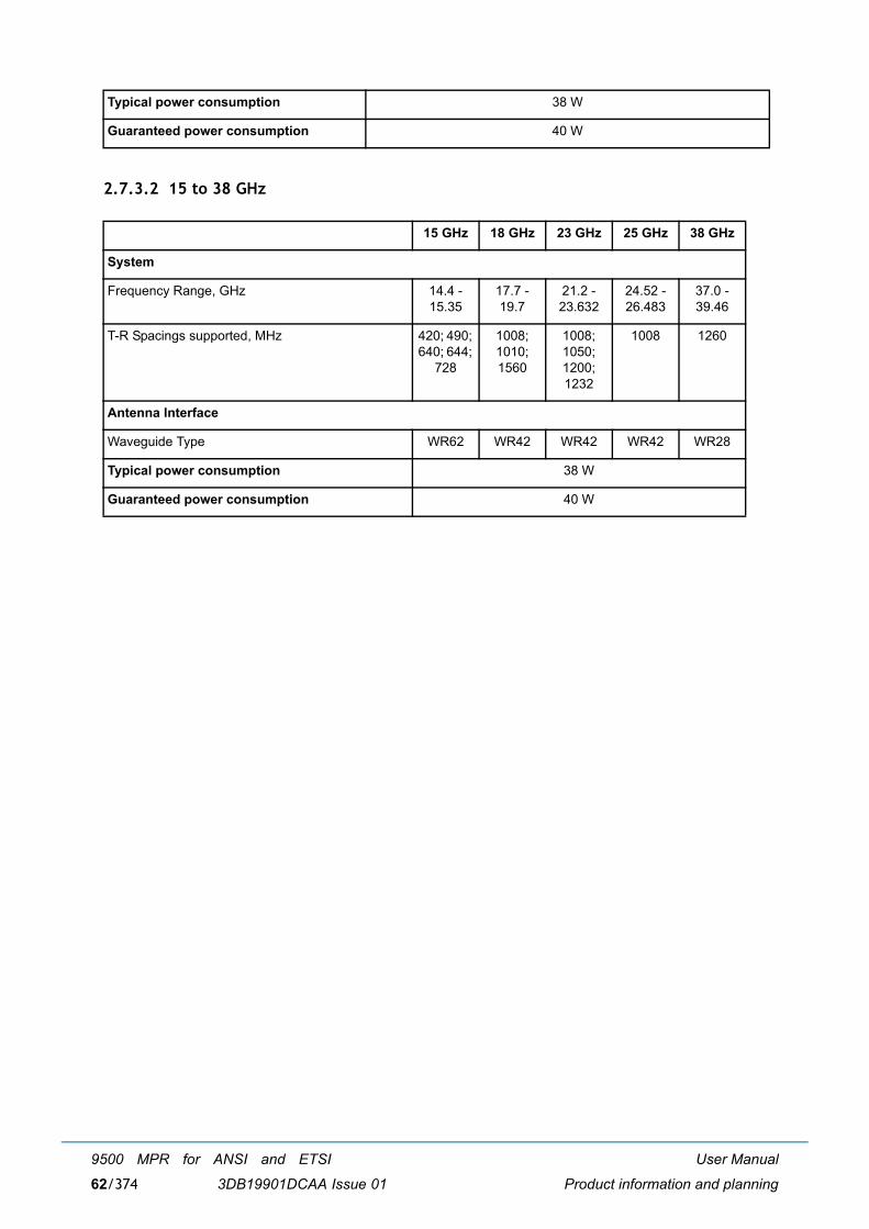
User Manual
Product information and planning
9500 MPR for ANSI and ETSI
3DB19901DCAA Issue 0162/374
2.7.3.2 15 to 38 GHz
Typical power consumption 38 W
Guaranteed power consumption 40 W
15 GHz 18 GHz 23 GHz 25 GHz 38 GHz
System
Frequency Range, GHz 14.4 - 15.35
17.7 - 19.7
21.2 - 23.632
24.52 - 26.483
37.0 - 39.46
T-R Spacings supported, MHz 420; 490; 640; 644;
728
1008; 1010; 1560
1008; 1050; 1200; 1232
1008 1260
Antenna Interface
Waveguide Type WR62 WR42 WR42 WR42 WR28
Typical power consumption 38 W
Guaranteed power consumption 40 W
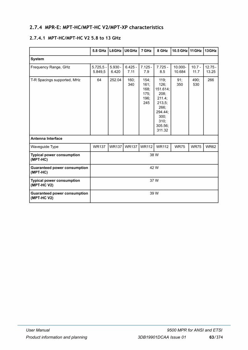
User Manual
Product information and planning
9500 MPR for ANSI and ETSI
3DB19901DCAA Issue 01 63/374
2.7.4 MPR-E: MPT-HC/MPT-HC V2/MPT-XP characteristics
2.7.4.1 MPT-HC/MPT-HC V2 5.8 to 13 GHz
5.8 GHz L6 GHz U6 GHz 7 GHz 8 GHz 10.5 GHz 11 GHz 13 GHz
System
Frequency Range, GHz 5.725,5 -5.849,5
5.930 - 6.420
6.425 - 7.11
7.125 - 7.9
7.725 - 8.5
10.000-10.684
10.7 - 11.7
12.75 - 13.25
T-R Spacings supported, MHz 64 252.04 160; 340
154; 161; 168; 175; 196; 245
119; 126;
151.614; 208;
211.4; 213,5; 266;
294.44; 300; 310;
305.56; 311.32
91;350
490; 530
266
Antenna Interface
Waveguide Type WR137 WR137 WR137 WR112 WR112 WR75 WR75 WR62
Typical power consumption (MPT-HC)
38 W
Guaranteed power consumption (MPT-HC)
42 W
Typical power consumption (MPT-HC V2)
37 W
Guaranteed power consumption (MPT-HC V2)
39 W
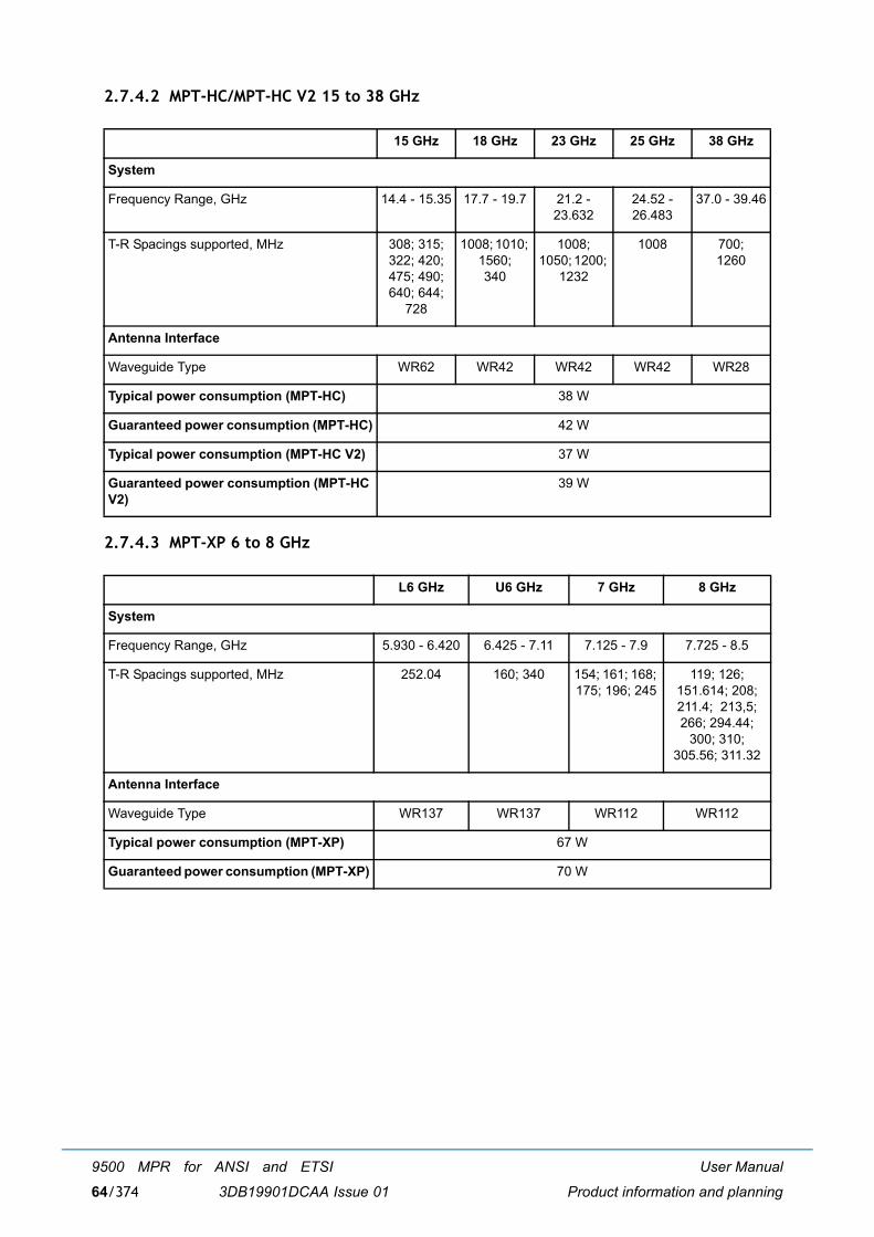
User Manual
Product information and planning
9500 MPR for ANSI and ETSI
3DB19901DCAA Issue 0164/374
2.7.4.2 MPT-HC/MPT-HC V2 15 to 38 GHz
2.7.4.3 MPT-XP 6 to 8 GHz
15 GHz 18 GHz 23 GHz 25 GHz 38 GHz
System
Frequency Range, GHz 14.4 - 15.35 17.7 - 19.7 21.2 - 23.632
24.52 - 26.483
37.0 - 39.46
T-R Spacings supported, MHz 308; 315; 322; 420; 475; 490; 640; 644;
728
1008; 1010; 1560; 340
1008; 1050; 1200;
1232
1008 700; 1260
Antenna Interface
Waveguide Type WR62 WR42 WR42 WR42 WR28
Typical power consumption (MPT-HC) 38 W
Guaranteed power consumption (MPT-HC) 42 W
Typical power consumption (MPT-HC V2) 37 W
Guaranteed power consumption (MPT-HC V2)
39 W
L6 GHz U6 GHz 7 GHz 8 GHz
System
Frequency Range, GHz 5.930 - 6.420 6.425 - 7.11 7.125 - 7.9 7.725 - 8.5
T-R Spacings supported, MHz 252.04 160; 340 154; 161; 168; 175; 196; 245
119; 126; 151.614; 208; 211.4; 213,5; 266; 294.44;
300; 310; 305.56; 311.32
Antenna Interface
Waveguide Type WR137 WR137 WR112 WR112
Typical power consumption (MPT-XP) 67 W
Guaranteed power consumption (MPT-XP) 70 W
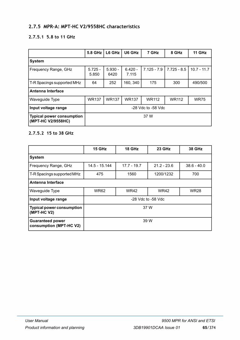
User Manual
Product information and planning
9500 MPR for ANSI and ETSI
3DB19901DCAA Issue 01 65/374
2.7.5 MPR-A: MPT-HC V2/9558HC characteristics
2.7.5.1 5.8 to 11 GHz
2.7.5.2 15 to 38 GHz
5.8 GHz L6 GHz U6 GHz 7 GHz 8 GHz 11 GHz
System
Frequency Range, GHz 5.725 -5.850
5.930 -6420
6.420 - 7.115
7.125 - 7.9 7.725 - 8.5 10.7 - 11.7
T-R Spacings supported MHz 64 252 160, 340 175 300 490/500
Antenna Interface
Waveguide Type WR137 WR137 WR137 WR112 WR112 WR75
Input voltage range -28 Vdc to -58 Vdc
Typical power consumption (MPT-HC V2/9558HC)
37 W
15 GHz 18 GHz 23 GHz 38 GHz
System
Frequency Range, GHz 14.5 - 15.144 17.7 - 19.7 21.2 - 23.6 38.6 - 40.0
T-R Spacings supported MHz 475 1560 1200/1232 700
Antenna Interface
Waveguide Type WR62 WR42 WR42 WR28
Input voltage range -28 Vdc to -58 Vdc
Typical power consumption (MPT-HC V2)
37 W
Guaranteed power consumption (MPT-HC V2)
39 W
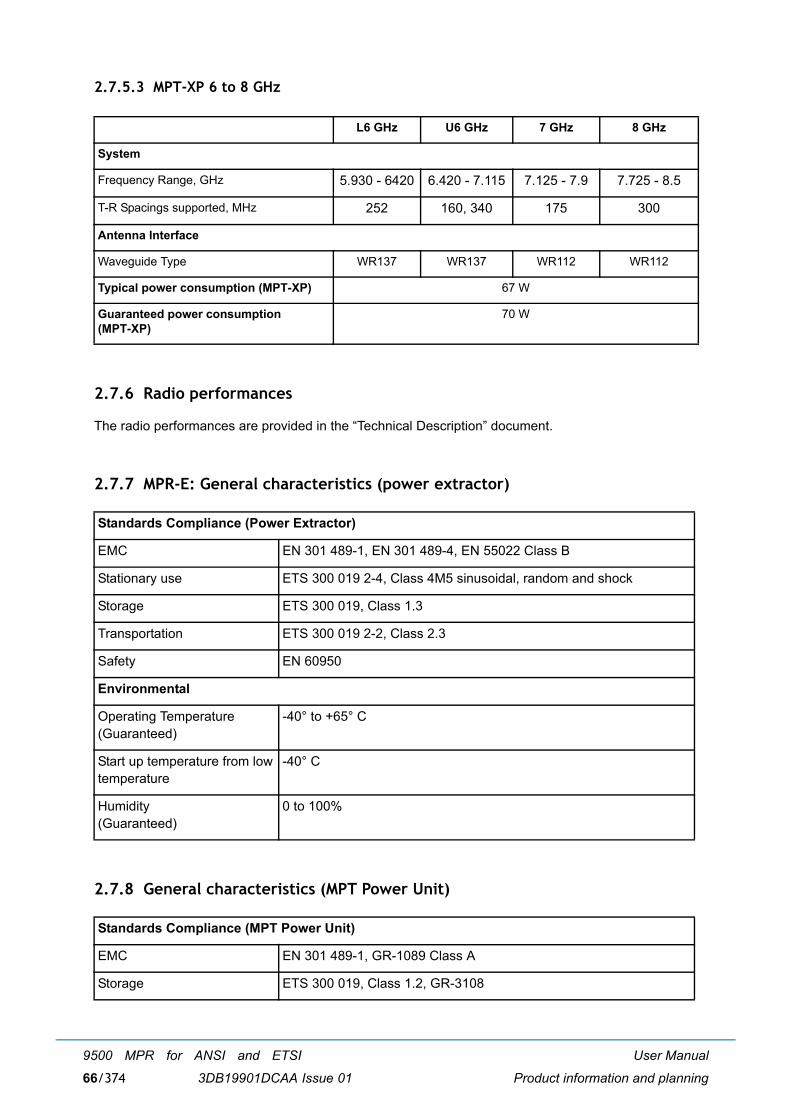
User Manual
Product information and planning
9500 MPR for ANSI and ETSI
3DB19901DCAA Issue 0166/374
2.7.5.3 MPT-XP 6 to 8 GHz
2.7.6 Radio performances
The radio performances are provided in the �Technical Description� document.
2.7.7 MPR-E: General characteristics (power extractor)
2.7.8 General characteristics (MPT Power Unit)
L6 GHz U6 GHz 7 GHz 8 GHz
System
Frequency Range, GHz 5.930 - 6420 6.420 - 7.115 7.125 - 7.9 7.725 - 8.5
T-R Spacings supported, MHz 252 160, 340 175 300
Antenna Interface
Waveguide Type WR137 WR137 WR112 WR112
Typical power consumption (MPT-XP) 67 W
Guaranteed power consumption (MPT-XP)
70 W
Standards Compliance (Power Extractor)
EMC EN 301 489-1, EN 301 489-4, EN 55022 Class B
Stationary use ETS 300 019 2-4, Class 4M5 sinusoidal, random and shock
Storage ETS 300 019, Class 1.3
Transportation ETS 300 019 2-2, Class 2.3
Safety EN 60950
Environmental
Operating Temperature(Guaranteed)
-40° to +65° C
Start up temperature from lowtemperature
-40° C
Humidity(Guaranteed)
0 to 100%
Standards Compliance (MPT Power Unit)
EMC EN 301 489-1, GR-1089 Class A
Storage ETS 300 019, Class 1.2, GR-3108
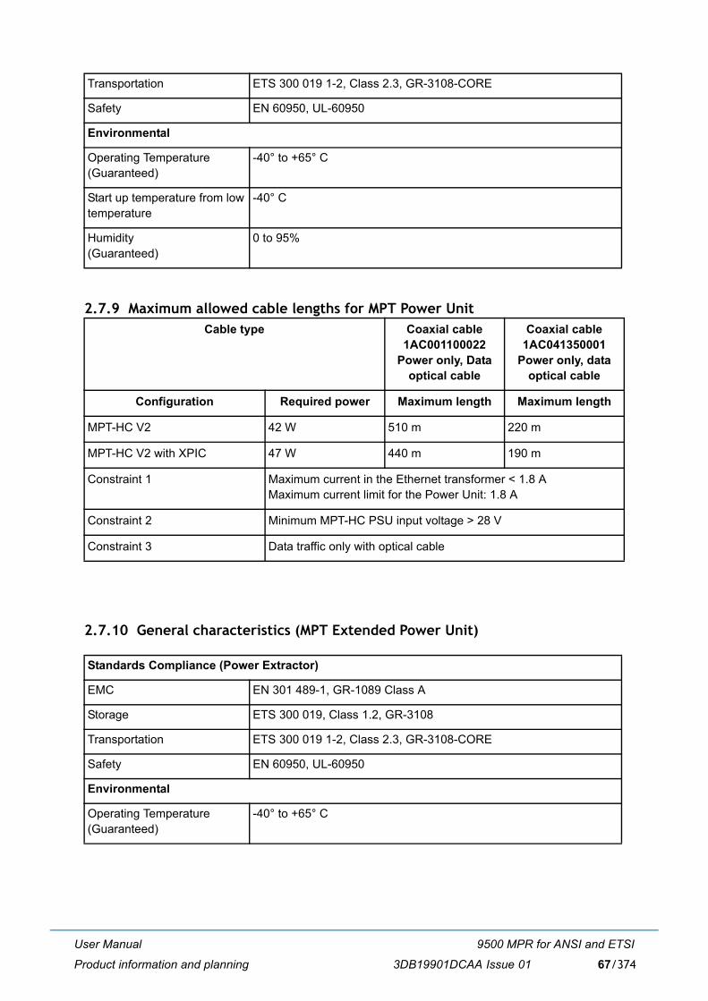
User Manual
Product information and planning
9500 MPR for ANSI and ETSI
3DB19901DCAA Issue 01 67/374
2.7.9 Maximum allowed cable lengths for MPT Power Unit
2.7.10 General characteristics (MPT Extended Power Unit)
Transportation ETS 300 019 1-2, Class 2.3, GR-3108-CORE
Safety EN 60950, UL-60950
Environmental
Operating Temperature(Guaranteed)
-40° to +65° C
Start up temperature from lowtemperature
-40° C
Humidity(Guaranteed)
0 to 95%
Cable type Coaxial cable 1AC001100022
Power only, Data optical cable
Coaxial cable 1AC041350001
Power only, data optical cable
Configuration Required power Maximum length Maximum length
MPT-HC V2 42 W 510 m 220 m
MPT-HC V2 with XPIC 47 W 440 m 190 m
Constraint 1 Maximum current in the Ethernet transformer < 1.8 AMaximum current limit for the Power Unit: 1.8 A
Constraint 2 Minimum MPT-HC PSU input voltage > 28 V
Constraint 3 Data traffic only with optical cable
Standards Compliance (Power Extractor)
EMC EN 301 489-1, GR-1089 Class A
Storage ETS 300 019, Class 1.2, GR-3108
Transportation ETS 300 019 1-2, Class 2.3, GR-3108-CORE
Safety EN 60950, UL-60950
Environmental
Operating Temperature(Guaranteed)
-40° to +65° C
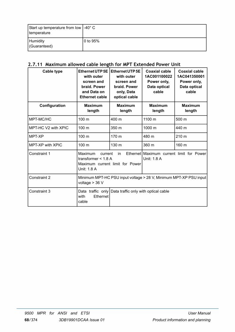
User Manual
Product information and planning
9500 MPR for ANSI and ETSI
3DB19901DCAA Issue 0168/374
2.7.11 Maximum allowed cable length for MPT Extended Power Unit
Start up temperature from lowtemperature
-40° C
Humidity(Guaranteed)
0 to 95%
Cable type Ethernet UTP 5E with outer screen and
braid. Power and Data on
Ethernet cable
Ethernet UTP 5E with outer screen and
braid. Power only, Data
optical cable
Coaxial cable 1AC001100022
Power only, Data optical
cable
Coaxial cable 1AC041350001
Power only, Data optical
cable
Configuration Maximum length
Maximum length
Maximum length
Maximum length
MPT-MC/HC 100 m 400 m 1100 m 500 m
MPT-HC V2 with XPIC 100 m 350 m 1000 m 440 m
MPT-XP 100 m 170 m 480 m 210 m
MPT-XP with XPIC 100 m 130 m 360 m 160 m
Constraint 1 Maximum current in Ethernettransformer < 1.8 A Maximum current limit for PowerUnit: 1.8 A
Maximum current limit for PowerUnit: 1.8 A
Constraint 2 Minimum MPT-HC PSU input voltage > 28 V, Minimum MPT-XP PSU inputvoltage > 36 V
Constraint 3 Data traffic onlywith Ethernetcable
Data traffic only with optical cable
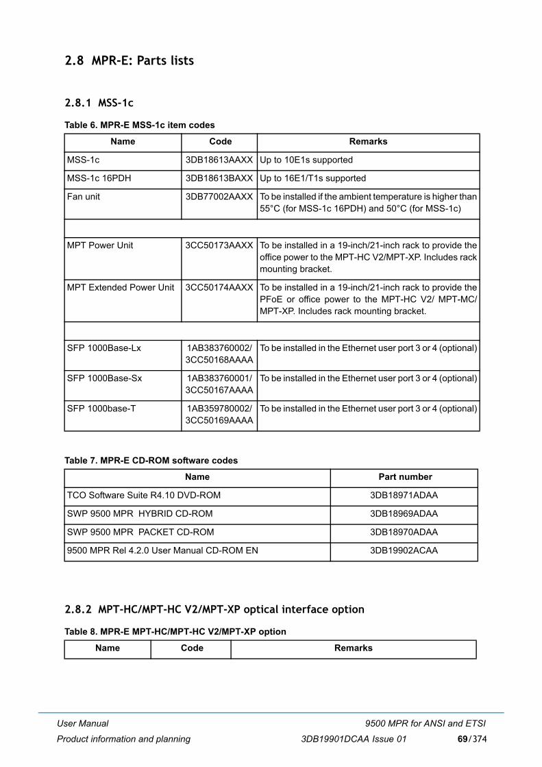
User Manual
Product information and planning
9500 MPR for ANSI and ETSI
3DB19901DCAA Issue 01 69/374
2.8 MPR-E: Parts lists
2.8.1 MSS-1c
Table 6. MPR-E MSS-1c item codes
Table 7. MPR-E CD-ROM software codes
2.8.2 MPT-HC/MPT-HC V2/MPT-XP optical interface option
Table 8. MPR-E MPT-HC/MPT-HC V2/MPT-XP option
Name Code Remarks
MSS-1c 3DB18613AAXX Up to 10E1s supported
MSS-1c 16PDH 3DB18613BAXX Up to 16E1/T1s supported
Fan unit 3DB77002AAXX To be installed if the ambient temperature is higher than55°C (for MSS-1c 16PDH) and 50°C (for MSS-1c)
MPT Power Unit 3CC50173AAXX To be installed in a 19-inch/21-inch rack to provide theoffice power to the MPT-HC V2/MPT-XP. Includes rackmounting bracket.
MPT Extended Power Unit 3CC50174AAXX To be installed in a 19-inch/21-inch rack to provide thePFoE or office power to the MPT-HC V2/ MPT-MC/MPT-XP. Includes rack mounting bracket.
SFP 1000Base-Lx 1AB383760002/3CC50168AAAA
To be installed in the Ethernet user port 3 or 4 (optional)
SFP 1000Base-Sx 1AB383760001/3CC50167AAAA
To be installed in the Ethernet user port 3 or 4 (optional)
SFP 1000base-T 1AB359780002/3CC50169AAAA
To be installed in the Ethernet user port 3 or 4 (optional)
Name Part number
TCO Software Suite R4.10 DVD-ROM 3DB18971ADAA
SWP 9500 MPR HYBRID CD-ROM 3DB18969ADAA
SWP 9500 MPR PACKET CD-ROM 3DB18970ADAA
9500 MPR Rel 4.2.0 User Manual CD-ROM EN 3DB19902ACAA
Name Code Remarks
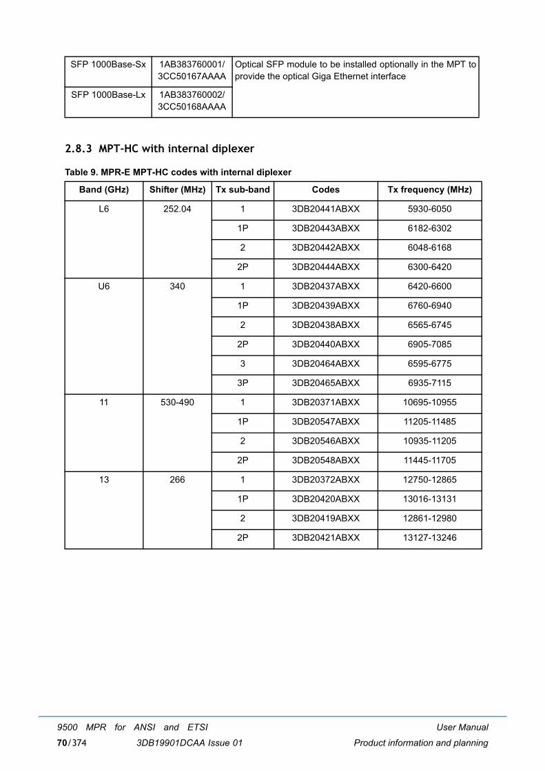
User Manual
Product information and planning
9500 MPR for ANSI and ETSI
3DB19901DCAA Issue 0170/374
2.8.3 MPT-HC with internal diplexer
Table 9. MPR-E MPT-HC codes with internal diplexer
SFP 1000Base-Sx 1AB383760001/3CC50167AAAA
Optical SFP module to be installed optionally in the MPT toprovide the optical Giga Ethernet interface
SFP 1000Base-Lx 1AB383760002/3CC50168AAAA
Band (GHz) Shifter (MHz) Tx sub-band Codes Tx frequency (MHz)
L6 252.04 1 3DB20441ABXX 5930-6050
1P 3DB20443ABXX 6182-6302
2 3DB20442ABXX 6048-6168
2P 3DB20444ABXX 6300-6420
U6 340 1 3DB20437ABXX 6420-6600
1P 3DB20439ABXX 6760-6940
2 3DB20438ABXX 6565-6745
2P 3DB20440ABXX 6905-7085
3 3DB20464ABXX 6595-6775
3P 3DB20465ABXX 6935-7115
11 530-490 1 3DB20371ABXX 10695-10955
1P 3DB20547ABXX 11205-11485
2 3DB20546ABXX 10935-11205
2P 3DB20548ABXX 11445-11705
13 266 1 3DB20372ABXX 12750-12865
1P 3DB20420ABXX 13016-13131
2 3DB20419ABXX 12861-12980
2P 3DB20421ABXX 13127-13246
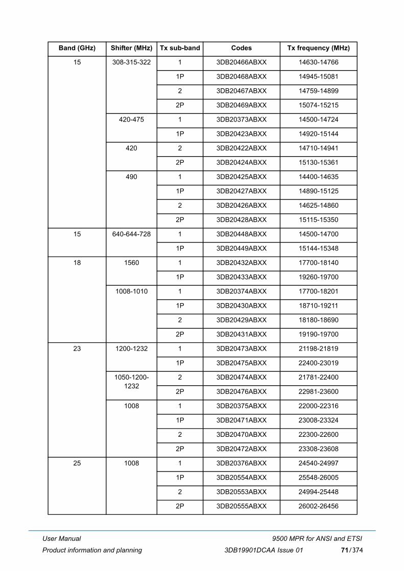
User Manual
Product information and planning
9500 MPR for ANSI and ETSI
3DB19901DCAA Issue 01 71/374
15 308-315-322 1 3DB20466ABXX 14630-14766
1P 3DB20468ABXX 14945-15081
2 3DB20467ABXX 14759-14899
2P 3DB20469ABXX 15074-15215
420-475 1 3DB20373ABXX 14500-14724
1P 3DB20423ABXX 14920-15144
420 2 3DB20422ABXX 14710-14941
2P 3DB20424ABXX 15130-15361
490 1 3DB20425ABXX 14400-14635
1P 3DB20427ABXX 14890-15125
2 3DB20426ABXX 14625-14860
2P 3DB20428ABXX 15115-15350
15 640-644-728 1 3DB20448ABXX 14500-14700
1P 3DB20449ABXX 15144-15348
18 1560 1 3DB20432ABXX 17700-18140
1P 3DB20433ABXX 19260-19700
1008-1010 1 3DB20374ABXX 17700-18201
1P 3DB20430ABXX 18710-19211
2 3DB20429ABXX 18180-18690
2P 3DB20431ABXX 19190-19700
23 1200-1232 1 3DB20473ABXX 21198-21819
1P 3DB20475ABXX 22400-23019
1050-1200-1232
2 3DB20474ABXX 21781-22400
2P 3DB20476ABXX 22981-23600
1008 1 3DB20375ABXX 22000-22316
1P 3DB20471ABXX 23008-23324
2 3DB20470ABXX 22300-22600
2P 3DB20472ABXX 23308-23608
25 1008 1 3DB20376ABXX 24540-24997
1P 3DB20554ABXX 25548-26005
2 3DB20553ABXX 24994-25448
2P 3DB20555ABXX 26002-26456
Band (GHz) Shifter (MHz) Tx sub-band Codes Tx frequency (MHz)
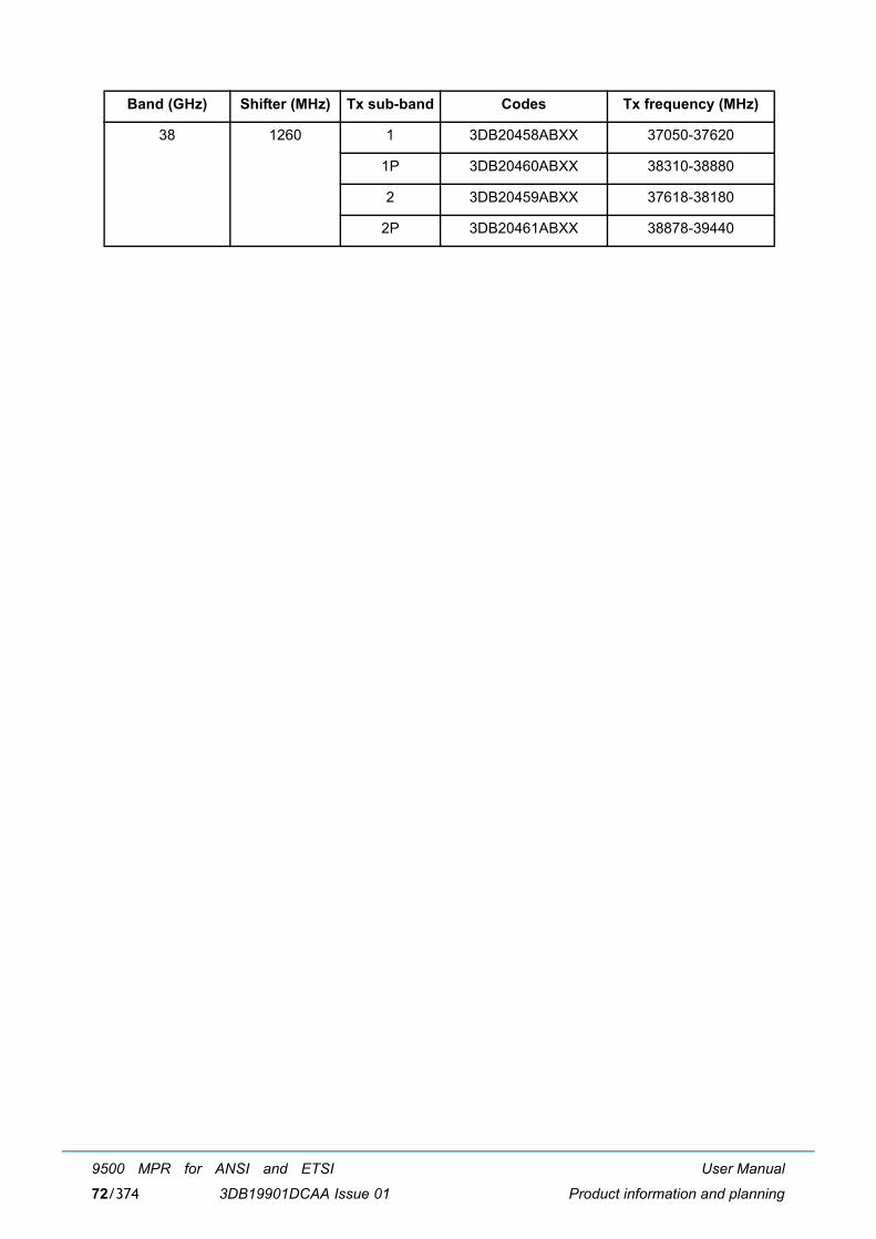
User Manual
Product information and planning
9500 MPR for ANSI and ETSI
3DB19901DCAA Issue 0172/374
38 1260 1 3DB20458ABXX 37050-37620
1P 3DB20460ABXX 38310-38880
2 3DB20459ABXX 37618-38180
2P 3DB20461ABXX 38878-39440
Band (GHz) Shifter (MHz) Tx sub-band Codes Tx frequency (MHz)
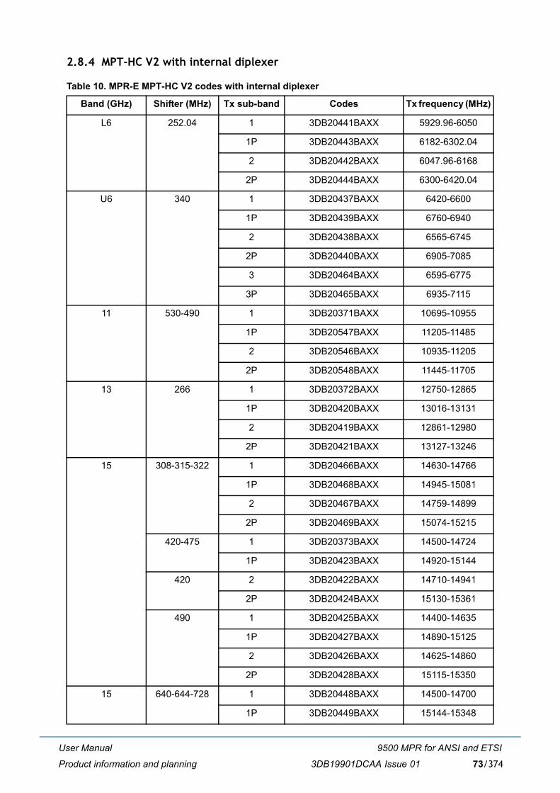
User Manual
Product information and planning
9500 MPR for ANSI and ETSI
3DB19901DCAA Issue 01 73/374
2.8.4 MPT-HC V2 with internal diplexer
Table 10. MPR-E MPT-HC V2 codes with internal diplexer
Band (GHz) Shifter (MHz) Tx sub-band Codes Tx frequency (MHz)
L6 252.04 1 3DB20441BAXX 5929.96-6050
1P 3DB20443BAXX 6182-6302.04
2 3DB20442BAXX 6047.96-6168
2P 3DB20444BAXX 6300-6420.04
U6 340 1 3DB20437BAXX 6420-6600
1P 3DB20439BAXX 6760-6940
2 3DB20438BAXX 6565-6745
2P 3DB20440BAXX 6905-7085
3 3DB20464BAXX 6595-6775
3P 3DB20465BAXX 6935-7115
11 530-490 1 3DB20371BAXX 10695-10955
1P 3DB20547BAXX 11205-11485
2 3DB20546BAXX 10935-11205
2P 3DB20548BAXX 11445-11705
13 266 1 3DB20372BAXX 12750-12865
1P 3DB20420BAXX 13016-13131
2 3DB20419BAXX 12861-12980
2P 3DB20421BAXX 13127-13246
15 308-315-322 1 3DB20466BAXX 14630-14766
1P 3DB20468BAXX 14945-15081
2 3DB20467BAXX 14759-14899
2P 3DB20469BAXX 15074-15215
420-475 1 3DB20373BAXX 14500-14724
1P 3DB20423BAXX 14920-15144
420 2 3DB20422BAXX 14710-14941
2P 3DB20424BAXX 15130-15361
490 1 3DB20425BAXX 14400-14635
1P 3DB20427BAXX 14890-15125
2 3DB20426BAXX 14625-14860
2P 3DB20428BAXX 15115-15350
15 640-644-728 1 3DB20448BAXX 14500-14700
1P 3DB20449BAXX 15144-15348
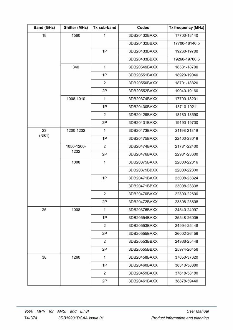
User Manual
Product information and planning
9500 MPR for ANSI and ETSI
3DB19901DCAA Issue 0174/374
18 1560 1 3DB20432BAXX 17700-18140
3DB20432BBXX 17700-18140.5
1P 3DB20433BAXX 19260-19700
3DB20433BBXX 19260-19700.5
340 1 3DB20549BAXX 18581-18700
1P 3DB20551BAXX 18920-19040
2 3DB20550BAXX 18701-18820
2P 3DB20552BAXX 19040-19160
1008-1010 1 3DB20374BAXX 17700-18201
1P 3DB20430BAXX 18710-19211
2 3DB20429BAXX 18180-18690
2P 3DB20431BAXX 19190-19700
23(NB1)
1200-1232 1 3DB20473BAXX 21198-21819
1P 3DB20475BAXX 22400-23019
1050-1200-1232
2 3DB20474BAXX 21781-22400
2P 3DB20476BAXX 22981-23600
1008 1 3DB20375BAXX 22000-22316
3DB20375BBXX 22000-22330
1P 3DB20471BAXX 23008-23324
3DB20471BBXX 23008-23338
2 3DB20470BAXX 22300-22600
2P 3DB20472BAXX 23308-23608
25 1008 1 3DB20376BAXX 24540-24997
1P 3DB20554BAXX 25548-26005
2 3DB20553BAXX 24994-25448
2P 3DB20555BAXX 26002-26456
2 3DB20553BBXX 24966-25448
2P 3DB20555BBXX 25974-26456
38 1260 1 3DB20458BAXX 37050-37620
1P 3DB20460BAXX 38310-38880
2 3DB20459BAXX 37618-38180
2P 3DB20461BAXX 38878-39440
Band (GHz) Shifter (MHz) Tx sub-band Codes Tx frequency (MHz)
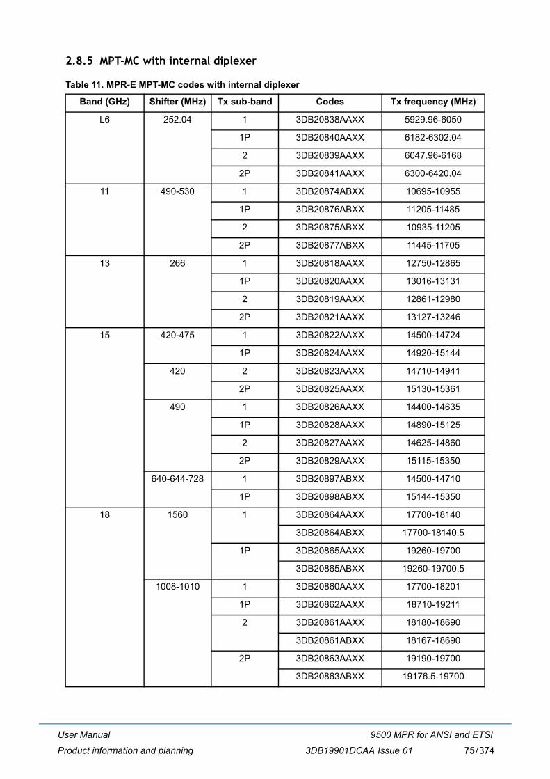
User Manual
Product information and planning
9500 MPR for ANSI and ETSI
3DB19901DCAA Issue 01 75/374
2.8.5 MPT-MC with internal diplexer
Table 11. MPR-E MPT-MC codes with internal diplexer
Band (GHz) Shifter (MHz) Tx sub-band Codes Tx frequency (MHz)
L6 252.04 1 3DB20838AAXX 5929.96-6050
1P 3DB20840AAXX 6182-6302.04
2 3DB20839AAXX 6047.96-6168
2P 3DB20841AAXX 6300-6420.04
11 490-530 1 3DB20874ABXX 10695-10955
1P 3DB20876ABXX 11205-11485
2 3DB20875ABXX 10935-11205
2P 3DB20877ABXX 11445-11705
13 266 1 3DB20818AAXX 12750-12865
1P 3DB20820AAXX 13016-13131
2 3DB20819AAXX 12861-12980
2P 3DB20821AAXX 13127-13246
15 420-475 1 3DB20822AAXX 14500-14724
1P 3DB20824AAXX 14920-15144
420 2 3DB20823AAXX 14710-14941
2P 3DB20825AAXX 15130-15361
490 1 3DB20826AAXX 14400-14635
1P 3DB20828AAXX 14890-15125
2 3DB20827AAXX 14625-14860
2P 3DB20829AAXX 15115-15350
640-644-728 1 3DB20897ABXX 14500-14710
1P 3DB20898ABXX 15144-15350
18 1560 1 3DB20864AAXX 17700-18140
3DB20864ABXX 17700-18140.5
1P 3DB20865AAXX 19260-19700
3DB20865ABXX 19260-19700.5
1008-1010 1 3DB20860AAXX 17700-18201
1P 3DB20862AAXX 18710-19211
2 3DB20861AAXX 18180-18690
3DB20861ABXX 18167-18690
2P 3DB20863AAXX 19190-19700
3DB20863ABXX 19176.5-19700
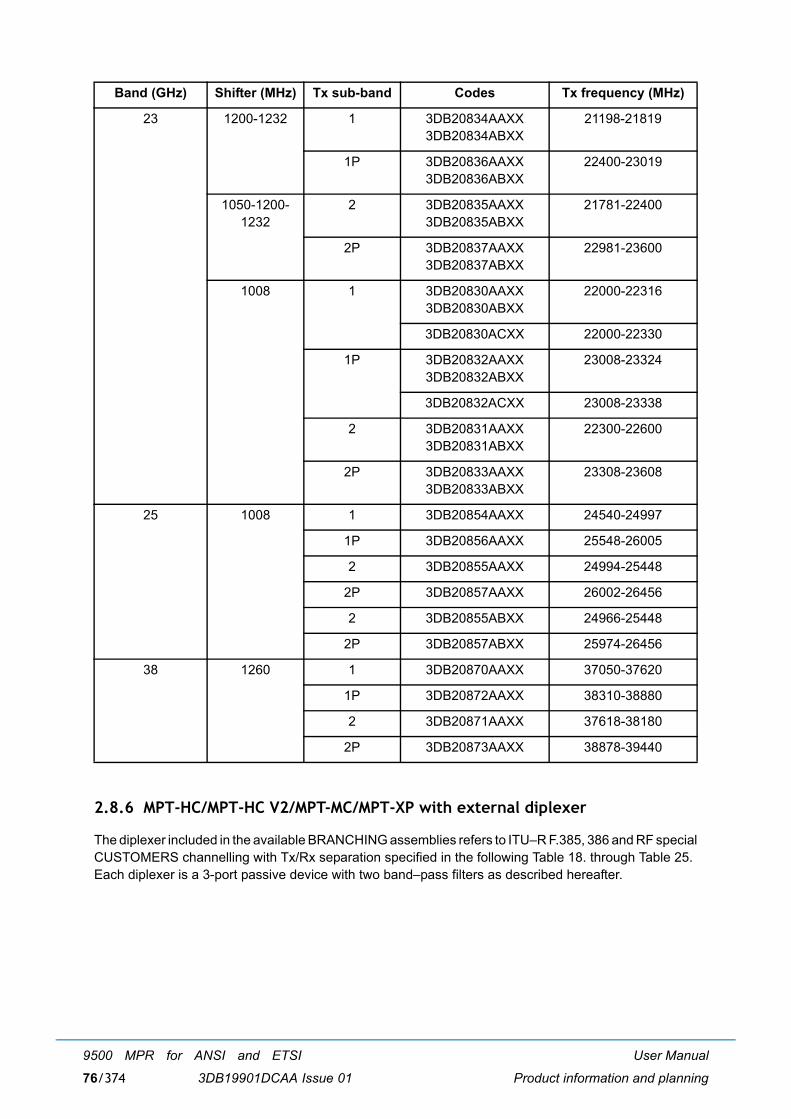
User Manual
Product information and planning
9500 MPR for ANSI and ETSI
3DB19901DCAA Issue 0176/374
2.8.6 MPT-HC/MPT-HC V2/MPT-MC/MPT-XP with external diplexer
The diplexer included in the available BRANCHING assemblies refers to ITU�R F.385, 386 and RF specialCUSTOMERS channelling with Tx/Rx separation specified in the following Table 18. through Table 25. Each diplexer is a 3-port passive device with two band�pass filters as described hereafter.
23 1200-1232 1 3DB20834AAXX3DB20834ABXX
21198-21819
1P 3DB20836AAXX3DB20836ABXX
22400-23019
1050-1200-1232
2 3DB20835AAXX3DB20835ABXX
21781-22400
2P 3DB20837AAXX3DB20837ABXX
22981-23600
1008 1 3DB20830AAXX3DB20830ABXX
22000-22316
3DB20830ACXX 22000-22330
1P 3DB20832AAXX3DB20832ABXX
23008-23324
3DB20832ACXX 23008-23338
2 3DB20831AAXX3DB20831ABXX
22300-22600
2P 3DB20833AAXX3DB20833ABXX
23308-23608
25 1008 1 3DB20854AAXX 24540-24997
1P 3DB20856AAXX 25548-26005
2 3DB20855AAXX 24994-25448
2P 3DB20857AAXX 26002-26456
2 3DB20855ABXX 24966-25448
2P 3DB20857ABXX 25974-26456
38 1260 1 3DB20870AAXX 37050-37620
1P 3DB20872AAXX 38310-38880
2 3DB20871AAXX 37618-38180
2P 3DB20873AAXX 38878-39440
Band (GHz) Shifter (MHz) Tx sub-band Codes Tx frequency (MHz)
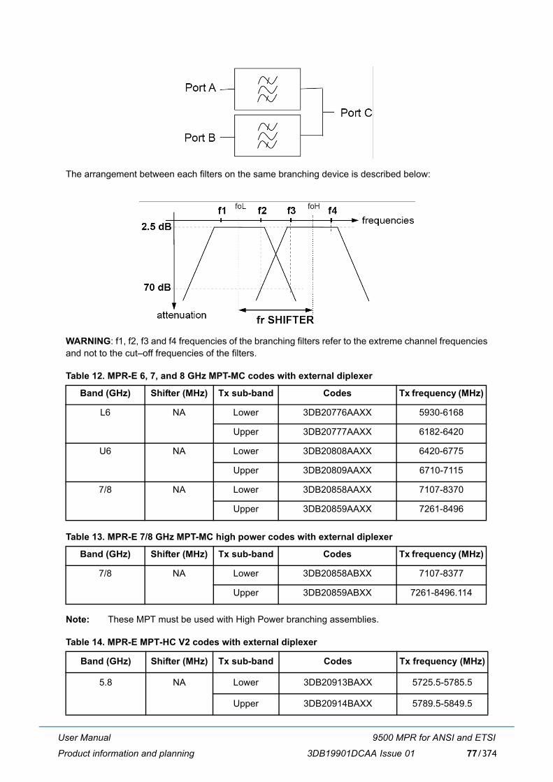
User Manual
Product information and planning
9500 MPR for ANSI and ETSI
3DB19901DCAA Issue 01 77/374
The arrangement between each filters on the same branching device is described below:
WARNING: f1, f2, f3 and f4 frequencies of the branching filters refer to the extreme channel frequenciesand not to the cut�off frequencies of the filters.
Table 12. MPR-E 6, 7, and 8 GHz MPT-MC codes with external diplexer
Table 13. MPR-E 7/8 GHz MPT-MC high power codes with external diplexer
Note: These MPT must be used with High Power branching assemblies.
Table 14. MPR-E MPT-HC V2 codes with external diplexer
Band (GHz) Shifter (MHz) Tx sub-band Codes Tx frequency (MHz)
L6 NA Lower 3DB20776AAXX 5930-6168
Upper 3DB20777AAXX 6182-6420
U6 NA Lower 3DB20808AAXX 6420-6775
Upper 3DB20809AAXX 6710-7115
7/8 NA Lower 3DB20858AAXX 7107-8370
Upper 3DB20859AAXX 7261-8496
Band (GHz) Shifter (MHz) Tx sub-band Codes Tx frequency (MHz)
7/8 NA Lower 3DB20858ABXX 7107-8377
Upper 3DB20859ABXX 7261-8496.114
Band (GHz) Shifter (MHz) Tx sub-band Codes Tx frequency (MHz)
5.8 NA Lower 3DB20913BAXX 5725.5-5785.5
Upper 3DB20914BAXX 5789.5-5849.5
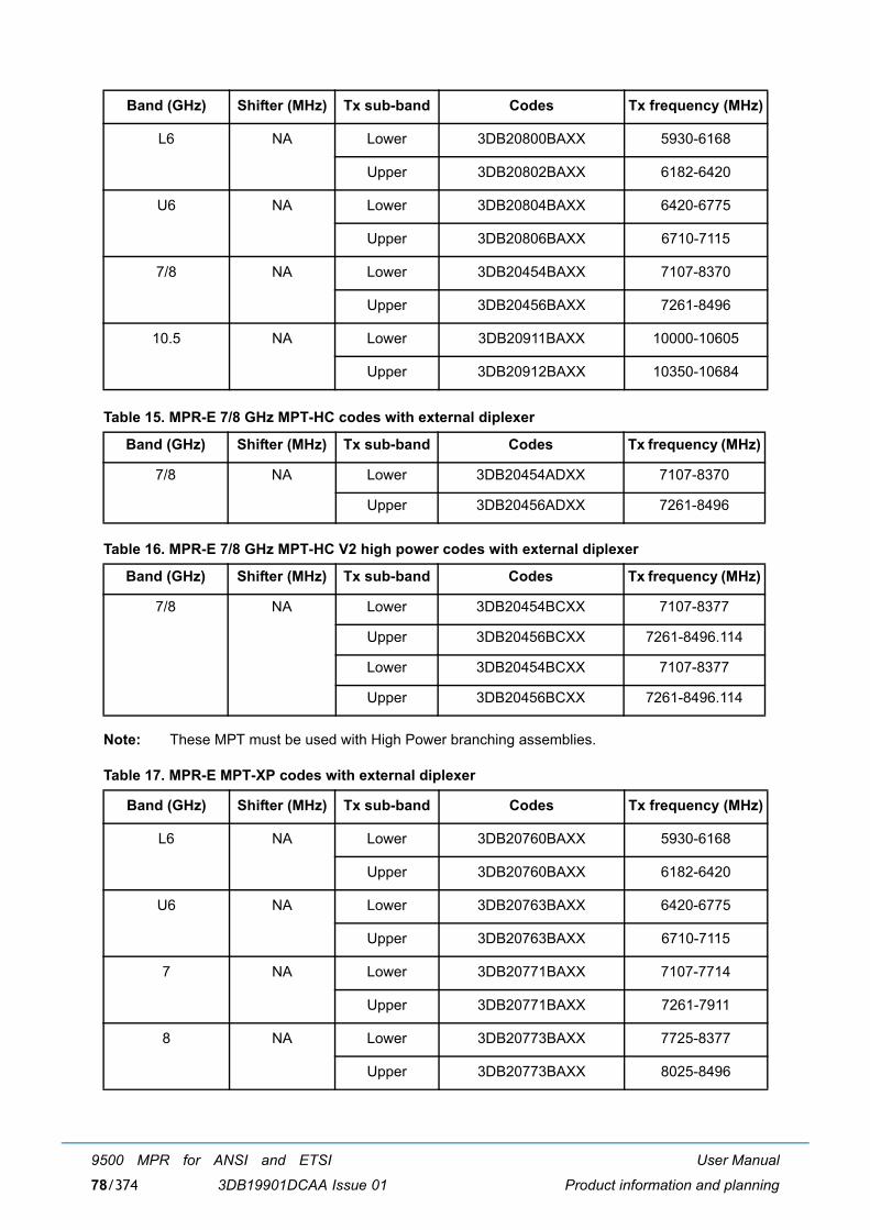
User Manual
Product information and planning
9500 MPR for ANSI and ETSI
3DB19901DCAA Issue 0178/374
Table 15. MPR-E 7/8 GHz MPT-HC codes with external diplexer
Table 16. MPR-E 7/8 GHz MPT-HC V2 high power codes with external diplexer
Note: These MPT must be used with High Power branching assemblies.
Table 17. MPR-E MPT-XP codes with external diplexer
L6 NA Lower 3DB20800BAXX 5930-6168
Upper 3DB20802BAXX 6182-6420
U6 NA Lower 3DB20804BAXX 6420-6775
Upper 3DB20806BAXX 6710-7115
7/8 NA Lower 3DB20454BAXX 7107-8370
Upper 3DB20456BAXX 7261-8496
10.5 NA Lower 3DB20911BAXX 10000-10605
Upper 3DB20912BAXX 10350-10684
Band (GHz) Shifter (MHz) Tx sub-band Codes Tx frequency (MHz)
7/8 NA Lower 3DB20454ADXX 7107-8370
Upper 3DB20456ADXX 7261-8496
Band (GHz) Shifter (MHz) Tx sub-band Codes Tx frequency (MHz)
7/8 NA Lower 3DB20454BCXX 7107-8377
Upper 3DB20456BCXX 7261-8496.114
Lower 3DB20454BCXX 7107-8377
Upper 3DB20456BCXX 7261-8496.114
Band (GHz) Shifter (MHz) Tx sub-band Codes Tx frequency (MHz)
L6 NA Lower 3DB20760BAXX 5930-6168
Upper 3DB20760BAXX 6182-6420
U6 NA Lower 3DB20763BAXX 6420-6775
Upper 3DB20763BAXX 6710-7115
7 NA Lower 3DB20771BAXX 7107-7714
Upper 3DB20771BAXX 7261-7911
8 NA Lower 3DB20773BAXX 7725-8377
Upper 3DB20773BAXX 8025-8496
Band (GHz) Shifter (MHz) Tx sub-band Codes Tx frequency (MHz)
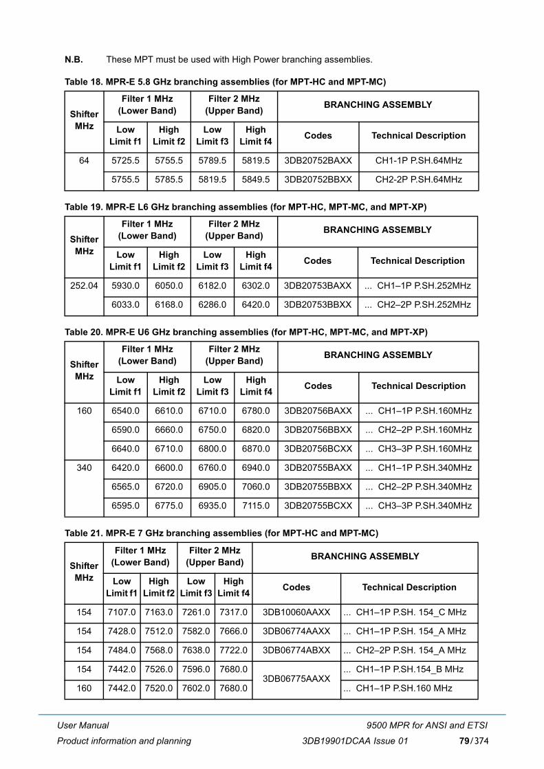
User Manual
Product information and planning
9500 MPR for ANSI and ETSI
3DB19901DCAA Issue 01 79/374
N.B. These MPT must be used with High Power branching assemblies.
Table 18. MPR-E 5.8 GHz branching assemblies (for MPT-HC and MPT-MC)
Table 19. MPR-E L6 GHz branching assemblies (for MPT-HC, MPT-MC, and MPT-XP)
Table 20. MPR-E U6 GHz branching assemblies (for MPT-HC, MPT-MC, and MPT-XP)
Table 21. MPR-E 7 GHz branching assemblies (for MPT-HC and MPT-MC)
Shifter MHz
Filter 1 MHz (Lower Band)
Filter 2 MHz(Upper Band) BRANCHING ASSEMBLY
Low Limit f1
High Limit f2
Low Limit f3
High Limit f4 Codes Technical Description
64 5725.5 5755.5 5789.5 5819.5 3DB20752BAXX CH1-1P P.SH.64MHz
5755.5 5785.5 5819.5 5849.5 3DB20752BBXX CH2-2P P.SH.64MHz
Shifter MHz
Filter 1 MHz (Lower Band)
Filter 2 MHz(Upper Band) BRANCHING ASSEMBLY
Low Limit f1
High Limit f2
Low Limit f3
High Limit f4 Codes Technical Description
252.04 5930.0 6050.0 6182.0 6302.0 3DB20753BAXX ... CH1�1P P.SH.252MHz
6033.0 6168.0 6286.0 6420.0 3DB20753BBXX ... CH2�2P P.SH.252MHz
Shifter MHz
Filter 1 MHz (Lower Band)
Filter 2 MHz(Upper Band) BRANCHING ASSEMBLY
Low Limit f1
High Limit f2
Low Limit f3
High Limit f4 Codes Technical Description
160 6540.0 6610.0 6710.0 6780.0 3DB20756BAXX ... CH1�1P P.SH.160MHz
6590.0 6660.0 6750.0 6820.0 3DB20756BBXX ... CH2�2P P.SH.160MHz
6640.0 6710.0 6800.0 6870.0 3DB20756BCXX ... CH3�3P P.SH.160MHz
340 6420.0 6600.0 6760.0 6940.0 3DB20755BAXX ... CH1�1P P.SH.340MHz
6565.0 6720.0 6905.0 7060.0 3DB20755BBXX ... CH2�2P P.SH.340MHz
6595.0 6775.0 6935.0 7115.0 3DB20755BCXX ... CH3�3P P.SH.340MHz
Shifter MHz
Filter 1 MHz (Lower Band)
Filter 2 MHz(Upper Band) BRANCHING ASSEMBLY
Low Limit f1
High Limit f2
Low Limit f3
High Limit f4 Codes Technical Description
154 7107.0 7163.0 7261.0 7317.0 3DB10060AAXX ... CH1�1P P.SH. 154_C MHz
154 7428.0 7512.0 7582.0 7666.0 3DB06774AAXX ... CH1�1P P.SH. 154_A MHz
154 7484.0 7568.0 7638.0 7722.0 3DB06774ABXX ... CH2�2P P.SH. 154_A MHz
154 7442.0 7526.0 7596.0 7680.03DB06775AAXX
... CH1�1P P.SH.154_B MHz
160 7442.0 7520.0 7602.0 7680.0 ... CH1�1P P.SH.160 MHz
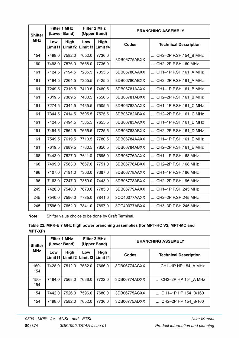
User Manual
Product information and planning
9500 MPR for ANSI and ETSI
3DB19901DCAA Issue 0180/374
Note: Shifter value choice to be done by Craft Terminal.
Table 22. MPR-E 7 GHz high power branching assemblies (for MPT-HC V2, MPT-MC andMPT-XP)
154 7498.0 7582.0 7652.0 7736.03DB06775ABXX
... CH2�2P P.SH.154_B MHz
160 7498.0 7576.0 7658.0 7736.0 ... CH2�2P P.SH.160 MHz
161 7124.5 7194.5 7285.5 7355.5 3DB06780AAXX ... CH1�1P P.SH.161_A MHz
161 7194.5 7264.5 7355.5 7425.5 3DB06780ABXX ... CH2�2P P.SH.161_A MHz
161 7249.5 7319.5 7410.5 7480.5 3DB06781AAXX ... CH1�1P P.SH.161_B MHz
161 7319.5 7389.5 7480.5 7550.5 3DB06781ABXX ... CH2�2P P.SH.161_B MHz
161 7274.5 7344.5 7435.5 7505.5 3DB06782AAXX ... CH1�1P P.SH.161_C MHz
161 7344.5 7414.5 7505.5 7575.5 3DB06782ABXX ... CH2�2P P.SH.161_C MHz
161 7424.5 7494.5 7585.5 7655.5 3DB06783AAXX ... CH1�1P P.SH.161_D MHz
161 7494.5 7564.5 7655.5 7725.5 3DB06783ABXX ... CH2�2P P.SH.161_D MHz
161 7549.5 7619.5 7710.5 7780.5 3DB06784AAXX ... CH1�1P P.SH.161_E MHz
161 7619.5 7689.5 7780.5 7850.5 3DB06784ABXX ... CH2�2P P.SH.161_E MHz
168 7443.0 7527.0 7611.0 7695.0 3DB06776AAXX ... CH1�1P P.SH.168 MHz
168 7499.0 7583.0 7667.0 7751.0 3DB06776ABXX ... CH2�2P P.SH.168 MHz
196 7107.0 7191.0 7303.0 7387.0 3DB06778AAXX ... CH1�1P P.SH.196 MHz
196 7163.0 7247.0 7359.0 7443.0 3DB06778ABXX ... CH2�2P P.SH.196 MHz
245 7428.0 7540.0 7673.0 7785.0 3DB06779AAXX ... CH1�1P P.SH.245 MHz
245 7540.0 7596.0 7785.0 7841.0 3CC40077AAXX ... CH2�2P P.SH.245 MHz
245 7596.0 7652.0 7841.0 7897.0 3CC40077ABXX ... CH3�3P P.SH.245 MHz
Shifter MHz
Filter 1 MHz (Lower Band)
Filter 2 MHz(Upper Band) BRANCHING ASSEMBLY
Low Limit f1
High Limit f2
Low Limit f3
High Limit f4 Codes Technical Description
150-154
7428.0 7512.0 7582.0 7666.0 3DB06774ACXX ... CH1�1P HP 154_A MHz
150-154
7484.0 7568.0 7638.0 7722.0 3DB06774ADXX ... CH2�2P HP 154_A MHz
154 7442.0 7526.0 7596.0 7680.0 3DB06775ACXX ... CH1�1P HP 154_B/160
154 7498.0 7582.0 7652.0 7736.0 3DB06775ADXX ... CH2�2P HP 154_B/160
Shifter MHz
Filter 1 MHz (Lower Band)
Filter 2 MHz(Upper Band) BRANCHING ASSEMBLY
Low Limit f1
High Limit f2
Low Limit f3
High Limit f4 Codes Technical Description
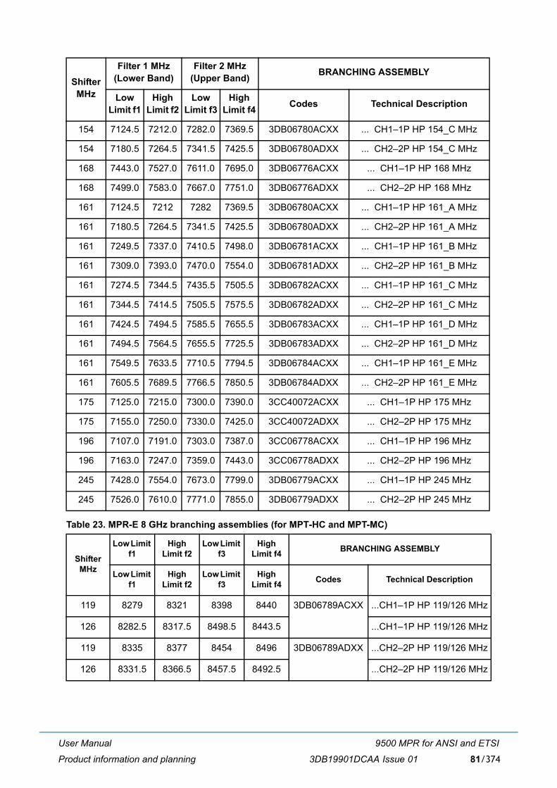
User Manual
Product information and planning
9500 MPR for ANSI and ETSI
3DB19901DCAA Issue 01 81/374
Table 23. MPR-E 8 GHz branching assemblies (for MPT-HC and MPT-MC)
154 7124.5 7212.0 7282.0 7369.5 3DB06780ACXX ... CH1�1P HP 154_C MHz
154 7180.5 7264.5 7341.5 7425.5 3DB06780ADXX ... CH2�2P HP 154_C MHz
168 7443.0 7527.0 7611.0 7695.0 3DB06776ACXX ... CH1�1P HP 168 MHz
168 7499.0 7583.0 7667.0 7751.0 3DB06776ADXX ... CH2�2P HP 168 MHz
161 7124.5 7212 7282 7369.5 3DB06780ACXX ... CH1�1P HP 161_A MHz
161 7180.5 7264.5 7341.5 7425.5 3DB06780ADXX ... CH2�2P HP 161_A MHz
161 7249.5 7337.0 7410.5 7498.0 3DB06781ACXX ... CH1�1P HP 161_B MHz
161 7309.0 7393.0 7470.0 7554.0 3DB06781ADXX ... CH2�2P HP 161_B MHz
161 7274.5 7344.5 7435.5 7505.5 3DB06782ACXX ... CH1�1P HP 161_C MHz
161 7344.5 7414.5 7505.5 7575.5 3DB06782ADXX ... CH2�2P HP 161_C MHz
161 7424.5 7494.5 7585.5 7655.5 3DB06783ACXX ... CH1�1P HP 161_D MHz
161 7494.5 7564.5 7655.5 7725.5 3DB06783ADXX ... CH2�2P HP 161_D MHz
161 7549.5 7633.5 7710.5 7794.5 3DB06784ACXX ... CH1�1P HP 161_E MHz
161 7605.5 7689.5 7766.5 7850.5 3DB06784ADXX ... CH2�2P HP 161_E MHz
175 7125.0 7215.0 7300.0 7390.0 3CC40072ACXX ... CH1�1P HP 175 MHz
175 7155.0 7250.0 7330.0 7425.0 3CC40072ADXX ... CH2�2P HP 175 MHz
196 7107.0 7191.0 7303.0 7387.0 3CC06778ACXX ... CH1�1P HP 196 MHz
196 7163.0 7247.0 7359.0 7443.0 3CC06778ADXX ... CH2�2P HP 196 MHz
245 7428.0 7554.0 7673.0 7799.0 3DB06779ACXX ... CH1�1P HP 245 MHz
245 7526.0 7610.0 7771.0 7855.0 3DB06779ADXX ... CH2�2P HP 245 MHz
Shifter MHz
Low Limit f1
High Limit f2
Low Limit f3
High Limit f4 BRANCHING ASSEMBLY
Low Limit f1
High Limit f2
Low Limit f3
High Limit f4 Codes Technical Description
119 8279 8321 8398 8440 3DB06789ACXX ...CH1�1P HP 119/126 MHz
126 8282.5 8317.5 8498.5 8443.5 ...CH1�1P HP 119/126 MHz
119 8335 8377 8454 8496 3DB06789ADXX ...CH2�2P HP 119/126 MHz
126 8331.5 8366.5 8457.5 8492.5 ...CH2�2P HP 119/126 MHz
Shifter MHz
Filter 1 MHz (Lower Band)
Filter 2 MHz(Upper Band) BRANCHING ASSEMBLY
Low Limit f1
High Limit f2
Low Limit f3
High Limit f4 Codes Technical Description
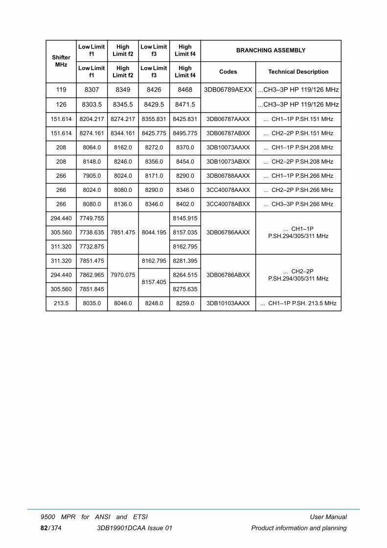
User Manual
Product information and planning
9500 MPR for ANSI and ETSI
3DB19901DCAA Issue 0182/374
119 8307 8349 8426 8468 3DB06789AEXX ...CH3�3P HP 119/126 MHz
126 8303.5 8345.5 8429.5 8471.5 ...CH3�3P HP 119/126 MHz
151.614 8204.217 8274.217 8355.831 8425.831 3DB06787AAXX ... CH1�1P P.SH.151 MHz
151.614 8274.161 8344.161 8425.775 8495.775 3DB06787ABXX ... CH2�2P P.SH.151 MHz
208 8064.0 8162.0 8272.0 8370.0 3DB10073AAXX ... CH1�1P P.SH.208 MHz
208 8148.0 8246.0 8356.0 8454.0 3DB10073ABXX ... CH2�2P P.SH.208 MHz
266 7905.0 8024.0 8171.0 8290.0 3DB06788AAXX ... CH1�1P P.SH.266 MHz
266 8024.0 8080.0 8290.0 8346.0 3CC40078AAXX ... CH2�2P P.SH.266 MHz
266 8080.0 8136.0 8346.0 8402.0 3CC40078ABXX ... CH3�3P P.SH.266 MHz
294.440 7749.755
7851.475 8044.195
8145.915
3DB06786AAXX ... CH1�1PP.SH.294/305/311 MHz305.560 7738.635 8157.035
311.320 7732.875 8162.795
311.320 7851.475
7970.075
8162.795 8281.395
3DB06786ABXX ... CH2�2PP.SH.294/305/311 MHz294.440 7862.965
8157.4058264.515
305.560 7851.845 8275.635
213.5 8035.0 8046.0 8248.0 8259.0 3DB10103AAXX ... CH1�1P P.SH. 213.5 MHz
Shifter MHz
Low Limit f1
High Limit f2
Low Limit f3
High Limit f4 BRANCHING ASSEMBLY
Low Limit f1
High Limit f2
Low Limit f3
High Limit f4 Codes Technical Description
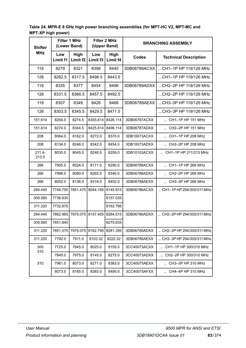
User Manual
Product information and planning
9500 MPR for ANSI and ETSI
3DB19901DCAA Issue 01 83/374
Table 24. MPR-E 8 GHz high power branching assemblies (for MPT-HC V2, MPT-MC and MPT-XP high power)
Shifter MHz
Filter 1 MHz (Lower Band)
Filter 2 MHz(Upper Band) BRANCHING ASSEMBLY
Low Limit f1
High Limit f2
Low Limit f3
High Limit f4 Codes Technical Description
119 8279 8321 8398 8440 3DB06789ACXX ...CH1�1P HP 119/126 MHz
126 8282.5 8317.5 8498.5 8443.5 ...CH1�1P HP 119/126 MHz
119 8335 8377 8454 8496 3DB06789ADXX ...CH2�2P HP 119/126 MHz
126 8331.5 8366.5 8457.5 8492.5 ...CH2�2P HP 119/126 MHz
119 8307 8349 8426 8468 3DB06789AEXX ...CH3�3P HP 119/126 MHz
126 8303.5 8345.5 8429.5 8471.5 ...CH3�3P HP 119/126 MHz
151.614 8204.0 8274.5 8355.614 8426.114 3DB06787ACXX ... CH1�1P HP 151 MHz
151.614 8274.0 8344.5 8425.614 8496.114 3DB06787ADXX ... CH2�2P HP 151 MHz
208 8064.0 8162.0 8272.0 8370.0 3DB10073ACXX ... CH1�1P HP 208 MHz
208 8134.0 8246.0 8342.0 8454.0 3DB10073ADXX ... CH2�2P HP 208 MHz
211.4-213.5
8035.0 8045.5 8248.5 8259.0 3DB10103ACXX ... CH1�1P HP 211/213 MHz
266 7905.0 8024.0 8171.0 8290.0 3DB06788ACXX ... CH1�1P HP 266 MHz
266 7996.0 8080.0 8262.0 8346.0 3DB06788ADXX ... CH2�2P HP 266 MHz
266 8052.0 8136.0 8318.0 8402.0 3DB06788AEXX ... CH3�3P HP 266 MHz
294.440 7749.755 7851.475 8044.195 8145.915 3DB06786ACXX ... CH1�1P HP 294/305/311 MHz
305.560 7738.635 8157.035
311.320 7732.875 8162.795
294.440 7862.965 7970.075 8157.405 8264.515 3DB06786ADXX ... CH2�2P HP 294/305/311 MHz
305.560 7851.845 8275.635
311.320 7851.475 7970.075 8162.795 8281.395 3DB06786ADXX ... CH2�2P HP 294/305/311 MHz
311.320 7792.0 7911.0 8103.32 8222.32 3DB06786AEXX ... CH3�3P HP 294/305/311 MHz
300310
7725.0 7845.0 8025.0 8155.0 3CC40073ACXX ... CH1�1P HP 300/310 MHz
7845.0 7975.0 8145.0 8275.0 3CC40073ADXX ... CH2�2P HP 300/310 MHz
310 7961.0 8073.0 8271.0 8383.0 3CC40075AEXX ... CH3�3P HP 310 MHz
8073.0 8185.0 8383.0 8495.0 3CC40075AFXX ... CH4�4P HP 310 MHz
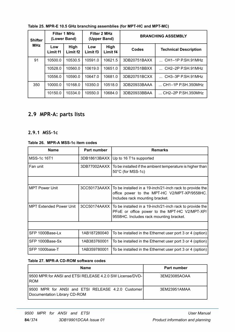
User Manual
Product information and planning
9500 MPR for ANSI and ETSI
3DB19901DCAA Issue 0184/374
Table 25. MPR-E 10.5 GHz branching assemblies (for MPT-HC and MPT-MC)
2.9 MPR-A: parts lists
2.9.1 MSS-1c
Table 26. MPR-A MSS-1c item codes
Table 27. MPR-A CD-ROM software codes
Shifter MHz
Filter 1 MHz (Lower Band)
Filter 2 MHz(Upper Band) BRANCHING ASSEMBLY
Low Limit f1
High Limit f2
Low Limit f3
High Limit f4 Codes Technical Description
91 10500.0 10530.5 10591.0 10621.5 3DB20751BAXX ... CH1�1P P.SH.91MHz
10528.0 10560.0 10619.0 10651.0 3DB20751BBXX ... CH2�2P P.SH.91MHz
10556.0 10590.0 10647.0 10681.0 3DB20751BCXX ... CH3�3P P.SH.91MHz
350 10000.0 10168.0 10350.0 10518.0 3DB20933BAAA ... CH1�1P P.SH.350MHz
10150.0 10334.0 10550.0 10684.0 3DB20933BBAA ... CH2�2P P.SH.350MHz
Name Part number Remarks
MSS-1c 16T1 3DB18613BAXX Up to 16 T1s supported
Fan unit 3DB77002AAXX To be installed if the ambient temperature is higher than50°C (for MSS-1c)
MPT Power Unit 3CC50173AAXX To be installed in a 19-inch/21-inch rack to provide theoffice power to the MPT-HC V2/MPT-XP/9558HC.Includes rack mounting bracket.
MPT Extended Power Unit 3CC50174AAXX To be installed in a 19-inch/21-inch rack to provide thePFoE or office power to the MPT-HC V2/MPT-XP/9558HC. Includes rack mounting bracket.
SFP 1000Base-Lx 1AB187280040 To be installed in the Ethernet user port 3 or 4 (option)
SFP 1000Base-Sx 1AB383760001 To be installed in the Ethernet user port 3 or 4 (option)
SFP 1000base-T 1AB359780001 To be installed in the Ethernet user port 3 or 4 (option)
Name Part number
9500 MPR for ANSI and ETSI RELEASE 4.2.0 SW License/DVD-ROM
3EM23085AOAA
9500 MPR for ANSI and ETSI RELEASE 4.2.0 CustomerDocumentation Library CD-ROM
3EM23951AMAA
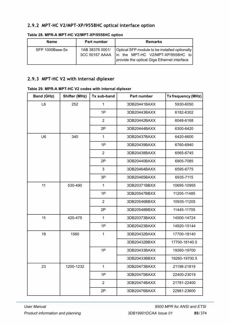
User Manual
Product information and planning
9500 MPR for ANSI and ETSI
3DB19901DCAA Issue 01 85/374
2.9.2 MPT-HC V2/MPT-XP/9558HC optical interface option
Table 28. MPR-A MPT-HC V2/MPT-XP/9558HC option
2.9.3 MPT-HC V2 with internal diplexer
Table 29. MPR-A MPT-HC V2 codes with internal diplexer
Name Part number Remarks
SFP 1000Base-Sx 1AB 38376 0001/3CC 50167 AAAA
Optical SFP module to be installed optionallyin the MPT-HC V2/MPT-XP/9558HC toprovide the optical Giga Ethernet interface
Band (GHz) Shifter (MHz) Tx sub-band Part number Tx frequency (MHz)
L6 252 1 3DB20441BAXX 5930-6050
1P 3DB20443BAXX 6182-6302
2 3DB20442BAXX 6048-6168
2P 3DB20444BAXX 6300-6420
U6 340 1 3DB20437BAXX 6420-6600
1P 3DB20439BAXX 6760-6940
2 3DB20438BAXX 6565-6745
2P 3DB20440BAXX 6905-7085
3 3DB20464BAXX 6595-6775
3P 3DB20465BAXX 6935-7115
11 530-490 1 3DB20371BBXX 10695-10955
1P 3DB20547BBXX 11205-11485
2 3DB20546BBXX 10935-11205
2P 3DB20548BBXX 11445-11705
15 420-475 1 3DB20373BAXX 14500-14724
1P 3DB20423BAXX 14920-15144
18 1560 1 3DB20432BAXX 17700-18140
3DB20432BBXX 17700-18140.5
1P 3DB20433BAXX 19260-19700
3DB20433BBXX 19260-19700.5
23 1200-1232 1 3DB20473BAXX 21198-21819
1P 3DB20475BAXX 22400-23019
2 3DB20474BAXX 21781-22400
2P 3DB20476BAXX 22981-23600
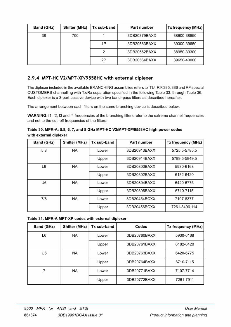
User Manual
Product information and planning
9500 MPR for ANSI and ETSI
3DB19901DCAA Issue 0186/374
2.9.4 MPT-HC V2/MPT-XP/9558HC with external diplexer
The diplexer included in the available BRANCHING assemblies refers to ITU�R F.385, 386 and RF specialCUSTOMERS channelling with Tx/Rx separation specified in the following Table 33. through Table 36. Each diplexer is a 3-port passive device with two band�pass filters as described hereafter.
The arrangement between each filters on the same branching device is described below:
WARNING: f1, f2, f3 and f4 frequencies of the branching filters refer to the extreme channel frequenciesand not to the cut�off frequencies of the filters.
Table 30. MPR-A: 5.8, 6, 7, and 8 GHz MPT-HC V2/MPT-XP/9558HC high power codes with external diplexer
Table 31. MPR-A MPT-XP codes with external diplexer
38 700 1 3DB20379BAXX 38600-38950
1P 3DB20563BAXX 39300-39650
2 3DB20562BAXX 38950-39300
2P 3DB20564BAXX 39650-40000
Band (GHz) Shifter (MHz) Tx sub-band Part number Tx frequency (MHz)
5.8 NA Lower 3DB20913BAXX 5725.5-5785.5
Upper 3DB20914BAXX 5789.5-5849.5
L6 NA Lower 3DB20800BAXX 5930-6168
Upper 3DB20802BAXX 6182-6420
U6 NA Lower 3DB20804BAXX 6420-6775
Upper 3DB20806BAXX 6710-7115
7/8 NA Lower 3DB20454BCXX 7107-8377
Upper 3DB20456BCXX 7261-8496.114
Band (GHz) Shifter (MHz) Tx sub-band Codes Tx frequency (MHz)
L6 NA Lower 3DB20760BAXX 5930-6168
Upper 3DB20761BAXX 6182-6420
U6 NA Lower 3DB20763BAXX 6420-6775
Upper 3DB20764BAXX 6710-7115
7 NA Lower 3DB20771BAXX 7107-7714
Upper 3DB20772BAXX 7261-7911
Band (GHz) Shifter (MHz) Tx sub-band Part number Tx frequency (MHz)
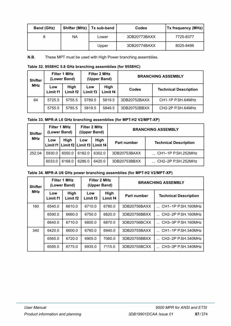
User Manual
Product information and planning
9500 MPR for ANSI and ETSI
3DB19901DCAA Issue 01 87/374
N.B. These MPT must be used with High Power branching assemblies.
Table 32. 9558HC 5.8 GHz branching assemblies (for 9558HC)
Table 33. MPR-A L6 GHz branching assemblies (for MPT-H2 V2/MPT-XP)
Table 34. MPR-A U6 GHz power branching assemblies (for MPT-H2 V2/MPT-XP)
8 NA Lower 3DB20773BAXX 7725-8377
Upper 3DB20774BAXX 8025-8496
Shifter MHz
Filter 1 MHz (Lower Band)
Filter 2 MHz(Upper Band) BRANCHING ASSEMBLY
Low Limit f1
High Limit f2
Low Limit f3
High Limit f4 Codes Technical Description
64 5725.5 5755.5 5789.5 5819.5 3DB20752BAXX CH1-1P P.SH.64MHz
5755.5 5785.5 5819.5 5849.5 3DB20752BBXX CH2-2P P.SH.64MHz
Shifter MHz
Filter 1 MHz (Lower Band)
Filter 2 MHz(Upper Band) BRANCHING ASSEMBLY
Low Limit f1
High Limit f2
Low Limit f3
High Limit f4 Part number Technical Description
252.04 5930.0 6050.0 6182.0 6302.0 3DB20753BAXX ... CH1�1P P.SH.252MHz
6033.0 6168.0 6286.0 6420.0 3DB20753BBXX ... CH2�2P P.SH.252MHz
Shifter MHz
Filter 1 MHz (Lower Band)
Filter 2 MHz(Upper Band) BRANCHING ASSEMBLY
Low Limit f1
High Limit f2
Low Limit f3
High Limit f4 Part number Technical Description
160 6540.0 6610.0 6710.0 6780.0 3DB20756BAXX ... CH1�1P P.SH.160MHz
6590.0 6660.0 6750.0 6820.0 3DB20756BBXX ... CH2�2P P.SH.160MHz
6640.0 6710.0 6800.0 6870.0 3DB20756BCXX ... CH3�3P P.SH.160MHz
340 6420.0 6600.0 6760.0 6940.0 3DB20755BAXX ... CH1�1P P.SH.340MHz
6565.0 6720.0 6905.0 7060.0 3DB20755BBXX ... CH2�2P P.SH.340MHz
6595.0 6775.0 6935.0 7115.0 3DB20755BCXX ... CH3�3P P.SH.340MHz
Band (GHz) Shifter (MHz) Tx sub-band Codes Tx frequency (MHz)
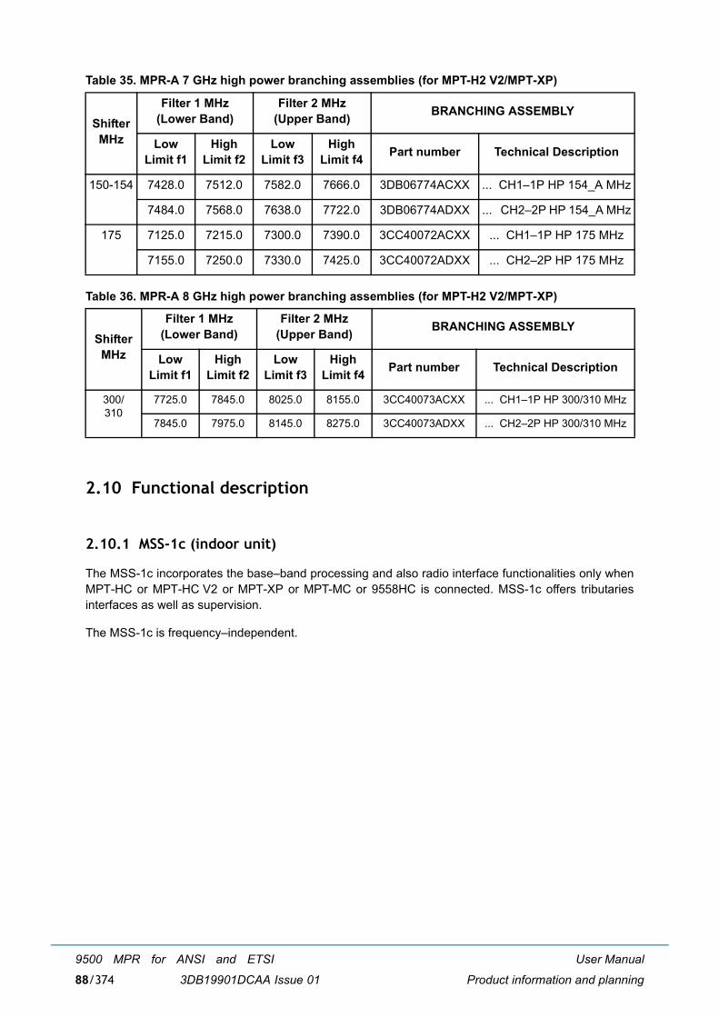
User Manual
Product information and planning
9500 MPR for ANSI and ETSI
3DB19901DCAA Issue 0188/374
Table 35. MPR-A 7 GHz high power branching assemblies (for MPT-H2 V2/MPT-XP)
Table 36. MPR-A 8 GHz high power branching assemblies (for MPT-H2 V2/MPT-XP)
2.10 Functional description
2.10.1 MSS-1c (indoor unit)
The MSS-1c incorporates the base�band processing and also radio interface functionalities only whenMPT-HC or MPT-HC V2 or MPT-XP or MPT-MC or 9558HC is connected. MSS-1c offers tributariesinterfaces as well as supervision.
The MSS-1c is frequency�independent.
Shifter MHz
Filter 1 MHz (Lower Band)
Filter 2 MHz(Upper Band) BRANCHING ASSEMBLY
Low Limit f1
High Limit f2
Low Limit f3
High Limit f4 Part number Technical Description
150-154 7428.0 7512.0 7582.0 7666.0 3DB06774ACXX ... CH1�1P HP 154_A MHz
7484.0 7568.0 7638.0 7722.0 3DB06774ADXX ... CH2�2P HP 154_A MHz
175 7125.0 7215.0 7300.0 7390.0 3CC40072ACXX ... CH1�1P HP 175 MHz
7155.0 7250.0 7330.0 7425.0 3CC40072ADXX ... CH2�2P HP 175 MHz
Shifter MHz
Filter 1 MHz (Lower Band)
Filter 2 MHz(Upper Band) BRANCHING ASSEMBLY
Low Limit f1
High Limit f2
Low Limit f3
High Limit f4 Part number Technical Description
300/310
7725.0 7845.0 8025.0 8155.0 3CC40073ACXX ... CH1�1P HP 300/310 MHz
7845.0 7975.0 8145.0 8275.0 3CC40073ADXX ... CH2�2P HP 300/310 MHz
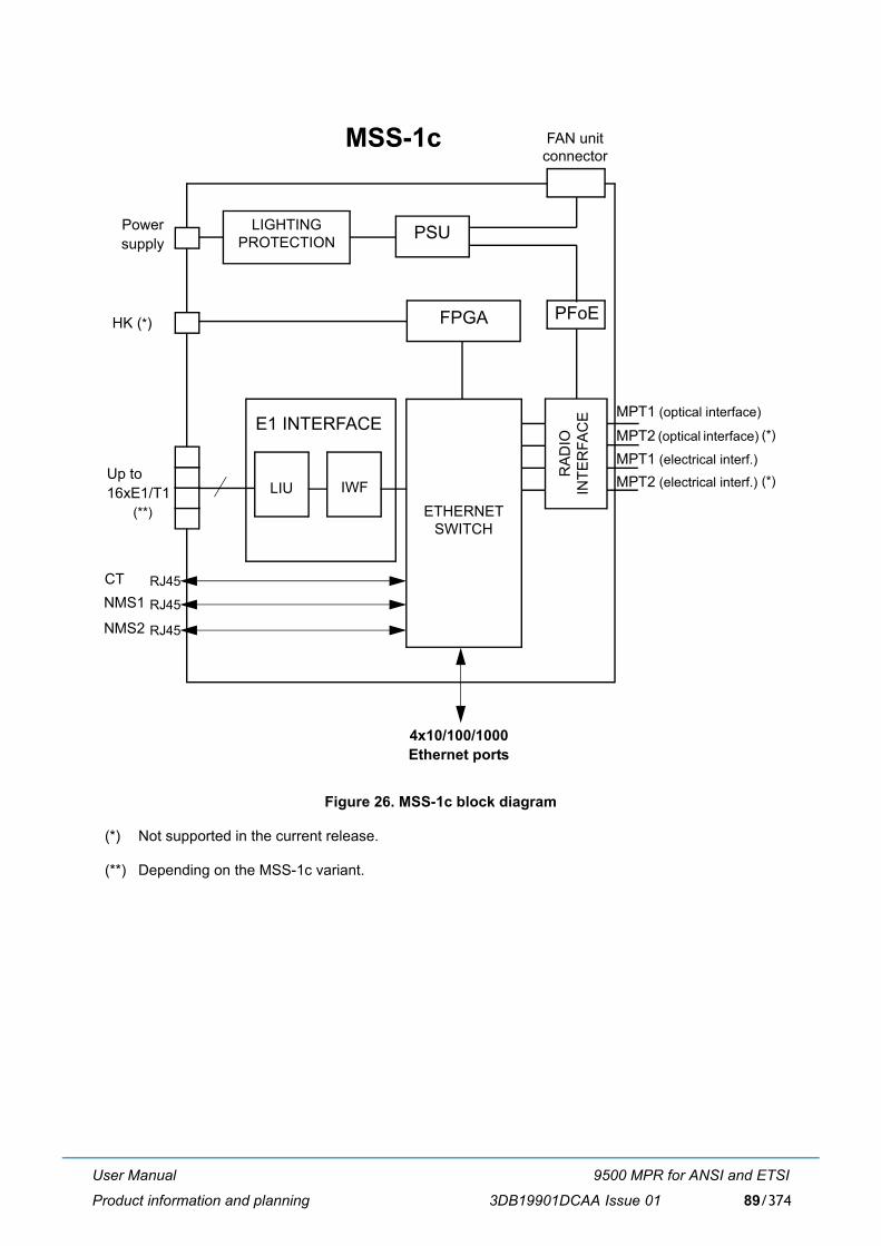
User Manual
Product information and planning
9500 MPR for ANSI and ETSI
3DB19901DCAA Issue 01 89/374
Figure 26. MSS-1c block diagram
(*) Not supported in the current release.
(**) Depending on the MSS-1c variant.
MSS-1c
PFoE
ETHERNETSWITCH
4x10/100/1000Ethernet ports
LIU IWF
HK (*)
Up to16xE1/T1
E1 INTERFACEMPT1 (optical interface)
MPT2 (optical interface)
MPT1 (electrical interf.)
MPT2 (electrical interf.)
Powersupply
LIGHTINGPROTECTION PSU
FPGA
FAN unit connector
CT RJ45NMS1 RJ45
RA
DIO
INTE
RFA
CE
NMS2 RJ45
(*)
(*)
(**)
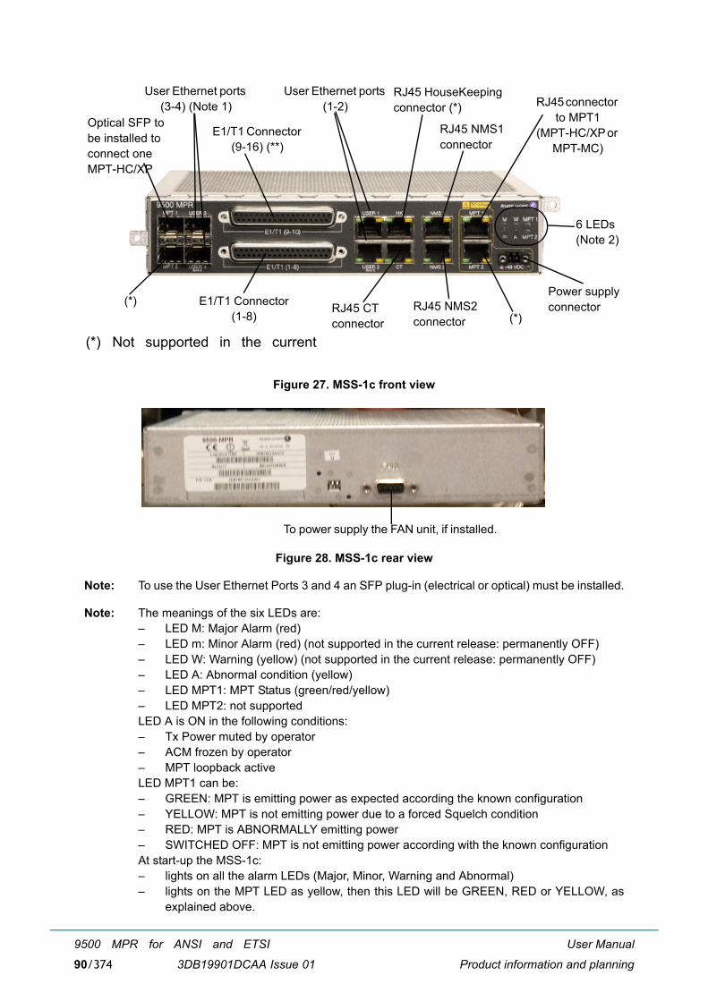
User Manual
Product information and planning
9500 MPR for ANSI and ETSI
3DB19901DCAA Issue 0190/374
Figure 27. MSS-1c front view
Figure 28. MSS-1c rear view
Note: To use the User Ethernet Ports 3 and 4 an SFP plug-in (electrical or optical) must be installed.
Note: The meanings of the six LEDs are: � LED M: Major Alarm (red)� LED m: Minor Alarm (red) (not supported in the current release: permanently OFF)� LED W: Warning (yellow) (not supported in the current release: permanently OFF)� LED A: Abnormal condition (yellow)� LED MPT1: MPT Status (green/red/yellow)� LED MPT2: not supportedLED A is ON in the following conditions:� Tx Power muted by operator� ACM frozen by operator� MPT loopback activeLED MPT1 can be:� GREEN: MPT is emitting power as expected according the known configuration� YELLOW: MPT is not emitting power due to a forced Squelch condition� RED: MPT is ABNORMALLY emitting power� SWITCHED OFF: MPT is not emitting power according with the known configurationAt start-up the MSS-1c:� lights on all the alarm LEDs (Major, Minor, Warning and Abnormal)� lights on the MPT LED as yellow, then this LED will be GREEN, RED or YELLOW, as
explained above.
Optical SFP tobe installed toconnect oneMPT-HC/XP
(*)
E1/T1 Connector (9-16) (**)
E1/T1 Connector (1-8)
User Ethernet ports (3-4) (Note 1)
User Ethernet ports (1-2)
RJ45 CTconnector
RJ45 HouseKeeping connector (*)
(*)RJ45 NMS2connector
RJ45 NMS1connector
RJ45 connector to MPT1
(MPT-HC/XP or MPT-MC)
6 LEDs(Note 2)
Power supplyconnector
(*) Not supported in the current
To power supply the FAN unit, if installed.
User Manual
Product information and planning
9500 MPR for ANSI and ETSI
3DB19901DCAA Issue 01 91/374
2.10.1.1 External user interface
� 2 traffic 10/100/1000 Base-T Ethernet interfaces for data and service traffic via RJ45 connector
Note: For 100 Ethernet interface the standard is 100Base-Tx.
� 2 SFP ready to accept optical 1000Base-LX/SX SFP or Electrical 1000Base-T SFP
� 2x 10/100 Ethernet NMS interfaces for connection of TMN on RJ45 connector
� 1 Local Craft terminal interface 10/100 Ethernet allows the straight connection to MPT remoteController via RJ45 connector
� 10E1 or 16E1/T1 bi-directional interfaces on 2 subD connectors
� 4 In housekeeping for external alarms collections, RJ45 connector + 2 IN/OUT (not supported)
� 9 poles SubD Connector in the rear side for FAN unit feed/control.
2.10.1.2 Power supply
The MSS-1c receives the Battery input through 1 power connector mounted on the front panel.
The input voltage range is from -38.4 V to -57.6 Vdc.
2.10.1.3 Ethernet switch
The switch provides the following features:
� Address learning up to 8K Mac address and static entries,
� Standard 802.1Q management (VLAN),
� Layer2 switching (MAC Address),
� 2 QoS per port (802.1P and DiffServ)
� Flexible output scheduler: SP (strict priority), DWRR (deficit weighted round robin).
2.10.1.4 E1/T1 interface
The E1/T1 Interface performs the following macro functions:
� MPR-E: Termination of 10E1 or 16E1 signals (E1 bi-directional interfaces according ITU-T G.703 onthe front panel)
� MPR-A: Termination of 16T1 signal with MSS-1c 16PDH variant (T1 bi-directional interfacesaccording to ANSI T1.403/TR 62411 on the front panel)
� Encapsulation/Extraction of those PDH data flows into/from standard Ethernet packets Inter WorkingFunction
� Reconstruction of the original PDH Timing
� Sending/getting those std Ethernet packets to the Ethernet switch
� Communication with the Controller for provisioning and status report.
User Manual
Product information and planning
9500 MPR for ANSI and ETSI
3DB19901DCAA Issue 0192/374
2.10.1.5 MPT interface
The MPT Interface is the interface for one MPT: MPT-HC or MPT-HC V2 or MPT-XP or MPT-MC or9558HC.
For the interconnections refer to paragraph 2.1.8 on page 43, paragraph 2.1.9 on page 46, paragraph2.1.10 on page 48 and paragraph 2.1.11 on page 50.
Main functions
� Provide the power supply interface and the Ethernet interface
� Provide the Power Feed over Ethernet function
� Lightning and surge protection
� Ethernet and power interface supervision
� Clock distribution function
� Ethernet link quality monitor function
� Communication with Controller for provisioning and status report.
2.10.1.6 Ethernet user interface
The following 4 Ethernet User Interfaces are available:
� 2 traffic 10/100/1000 Base-T Ethernet interfaces for data and service traffic via RJ45 connector. N.B. For 100 Ethernet interface the standard is 100Base-Tx.
� 2 SFP ready to accept optical 1000Base-LX/SX SFP or Electrical 1000Base-T SFP.
The User port 2 can be used as SynchE synchronization.
The User port 3 (*) and port 4 can be used as SynchE synchronization in optical mode.
(*): MPR-E: User port 3 is not available as a synchronization source on the MSS-1c variant.
2.10.2 Fan unit
An optional Fan unit must be used to dissipate the MSS-1c in the special case when the ambienttemperature is > +50°C (MSS-1c) or >+55°C (MSS-1c 16PDH).
Figure 29. shows the installation position: the MSS-1c on the right and the Fan unit on the left.
The MSS-1c and the Fan unit are mounted on a bracket compatible with 19" rack. Height is 1.3U.
The Fan unit is powered by the MSS-1c with a cable placed on the rear side. The cable is provided withthe Fan unit.
The Fan unit includes two fans.
One bi-color LED on the front panel gives the status of the Fan unit:
� Fans alarm = OFF <-> LED = green
� Fans alarm = ON <-> LED = red
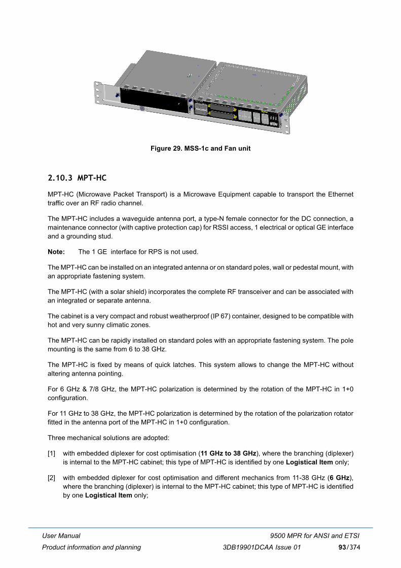
User Manual
Product information and planning
9500 MPR for ANSI and ETSI
3DB19901DCAA Issue 01 93/374
Figure 29. MSS-1c and Fan unit
2.10.3 MPT-HC
MPT-HC (Microwave Packet Transport) is a Microwave Equipment capable to transport the Ethernettraffic over an RF radio channel.
The MPT-HC includes a waveguide antenna port, a type-N female connector for the DC connection, amaintenance connector (with captive protection cap) for RSSI access, 1 electrical or optical GE interfaceand a grounding stud.
Note: The 1 GE interface for RPS is not used.
The MPT-HC can be installed on an integrated antenna or on standard poles, wall or pedestal mount, withan appropriate fastening system.
The MPT-HC (with a solar shield) incorporates the complete RF transceiver and can be associated withan integrated or separate antenna.
The cabinet is a very compact and robust weatherproof (IP 67) container, designed to be compatible withhot and very sunny climatic zones.
The MPT-HC can be rapidly installed on standard poles with an appropriate fastening system. The polemounting is the same from 6 to 38 GHz.
The MPT-HC is fixed by means of quick latches. This system allows to change the MPT-HC withoutaltering antenna pointing.
For 6 GHz & 7/8 GHz, the MPT-HC polarization is determined by the rotation of the MPT-HC in 1+0configuration.
For 11 GHz to 38 GHz, the MPT-HC polarization is determined by the rotation of the polarization rotatorfitted in the antenna port of the MPT-HC in 1+0 configuration.
Three mechanical solutions are adopted:
[1] with embedded diplexer for cost optimisation (11 GHz to 38 GHz), where the branching (diplexer)is internal to the MPT-HC cabinet; this type of MPT-HC is identified by one Logistical Item only;
[2] with embedded diplexer for cost optimisation and different mechanics from 11-38 GHz (6 GHz),where the branching (diplexer) is internal to the MPT-HC cabinet; this type of MPT-HC is identifiedby one Logistical Item only;
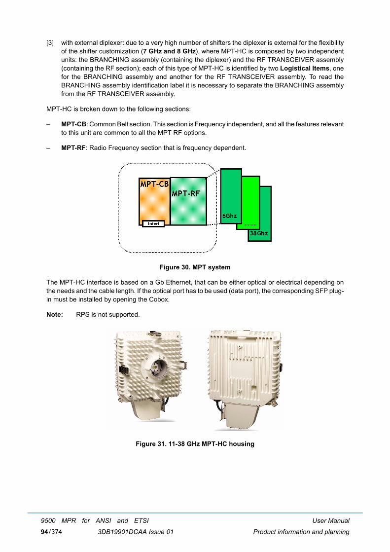
User Manual
Product information and planning
9500 MPR for ANSI and ETSI
3DB19901DCAA Issue 0194/374
[3] with external diplexer: due to a very high number of shifters the diplexer is external for the flexibilityof the shifter customization (7 GHz and 8 GHz), where MPT-HC is composed by two independentunits: the BRANCHING assembly (containing the diplexer) and the RF TRANSCEIVER assembly(containing the RF section); each of this type of MPT-HC is identified by two Logistical Items, onefor the BRANCHING assembly and another for the RF TRANSCEIVER assembly. To read theBRANCHING assembly identification label it is necessary to separate the BRANCHING assemblyfrom the RF TRANSCEIVER assembly.
MPT-HC is broken down to the following sections:
� MPT-CB: Common Belt section. This section is Frequency independent, and all the features relevantto this unit are common to all the MPT RF options.
� MPT-RF: Radio Frequency section that is frequency dependent.
Figure 30. MPT system
The MPT-HC interface is based on a Gb Ethernet, that can be either optical or electrical depending onthe needs and the cable length. If the optical port has to be used (data port), the corresponding SFP plug-in must be installed by opening the Cobox.
Note: RPS is not supported.
Figure 31. 11-38 GHz MPT-HC housing
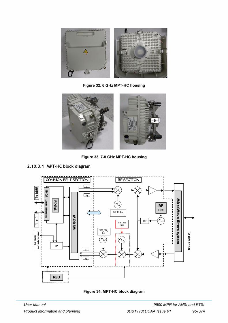
User Manual
Product information and planning
9500 MPR for ANSI and ETSI
3DB19901DCAA Issue 01 95/374
Figure 32. 6 GHz MPT-HC housing
Figure 33. 7-8 GHz MPT-HC housing
2.10.3.1 MPT-HC block diagram
Figure 34. MPT-HC block diagram

User Manual
Product information and planning
9500 MPR for ANSI and ETSI
3DB19901DCAA Issue 0196/374
2.10.3.1.1 Common belt section
The Common Belt section is frequency independent. It is the digital section of the MPT-HC.
The main functions are the following:
1) Interfaces the MSS for traffic transport and MSS communication messages in both directions,through one Gigabit Ethernet optical or electrical cable.
2) Micro-Processor for
� Indoor - MPT-HC dialogue � HW configuration and monitoring of all MPT-HC parts� Dynamic regulation process such as ATPC
3) Transport of the system reference clock (synchronisation)
4) Switches the traffic and management to the correct port (processor port, radio port)
5) Performs traffic adaptation if needed
6) Performs Quality of Service and policing on flow to be sent over the radio link.
7) Modulation and demodulation of the resulting modem frame
Power supply interface
The power supply is coming from the MSS in the range of -40,5 V to -58 V. MPT-HC input voltage rangeis from -28 V to -58 V.
Lightning protection
The lightning protection is internal to the MPT-HC. No external protection must be used.
This protection applies to:
� the Ethernet electrical cables
� the power supply coax cable
INCA module
The INCA module hosts the physical electrical Ethernet interface.
Tx side
Following the flow from user Ethernet port to radio, the section performs:
� Reception of incoming Ethernet frames from the optical or electrical user interface (through INCA)
� Recovery of the clock coming from the MSS
� Switch of the management frames from user port to internal processor
� Generation of MPT-HC to MPT-HC messages needed for radio link (ATPC, ACM)
� Compression of the TDMoEth frames header (TDM2TDM - MEF8, TDM2ETH - MEF8)
� Management of the Quality of Service
� Fragmentation of the Ethernet frames

User Manual
Product information and planning
9500 MPR for ANSI and ETSI
3DB19901DCAA Issue 01 97/374
� Shaping of the traffic to adapt it to radio bandwidth
� Tx Modem frame building
� Tx Radio frame building (FEC, pilots)
� Synchronisation of the symbol rate to the MSS recovered clock
� Modulation in I and Q analogue signals to be sent to the RF section.
Rx side
Following the flow from radio to user Ethernet port, the section performs:
� Reception of the I and Q analogue signals coming from the RF section
� Demodulation of the Rx radio frame into Rx modem frame
� Deframing of the Rx modem frame
� Re-assembly of fragmented Ethernet frame
� Decompression of TDMoEth frames header
� Extraction of MPT-HC to MPT-HC messages needed for radio link (ATPC, ACM)
� Management of service channels frames
� Switch of the management frames from internal processor to user port.
� Send the recovered clock to the MSS
2.10.3.1.2 RF section
There are two architectures, the difference between these two architectures are only on Rx side:
� For the first one (used in MPT-HC band 7/8 GHz) there are only two frequency conversions betweenRF input frequency and base band frequency
� For the second one (used for all other MPT-HC bands) there are three frequency conversions
The block diagrams of these two architectures are shown hereafter.
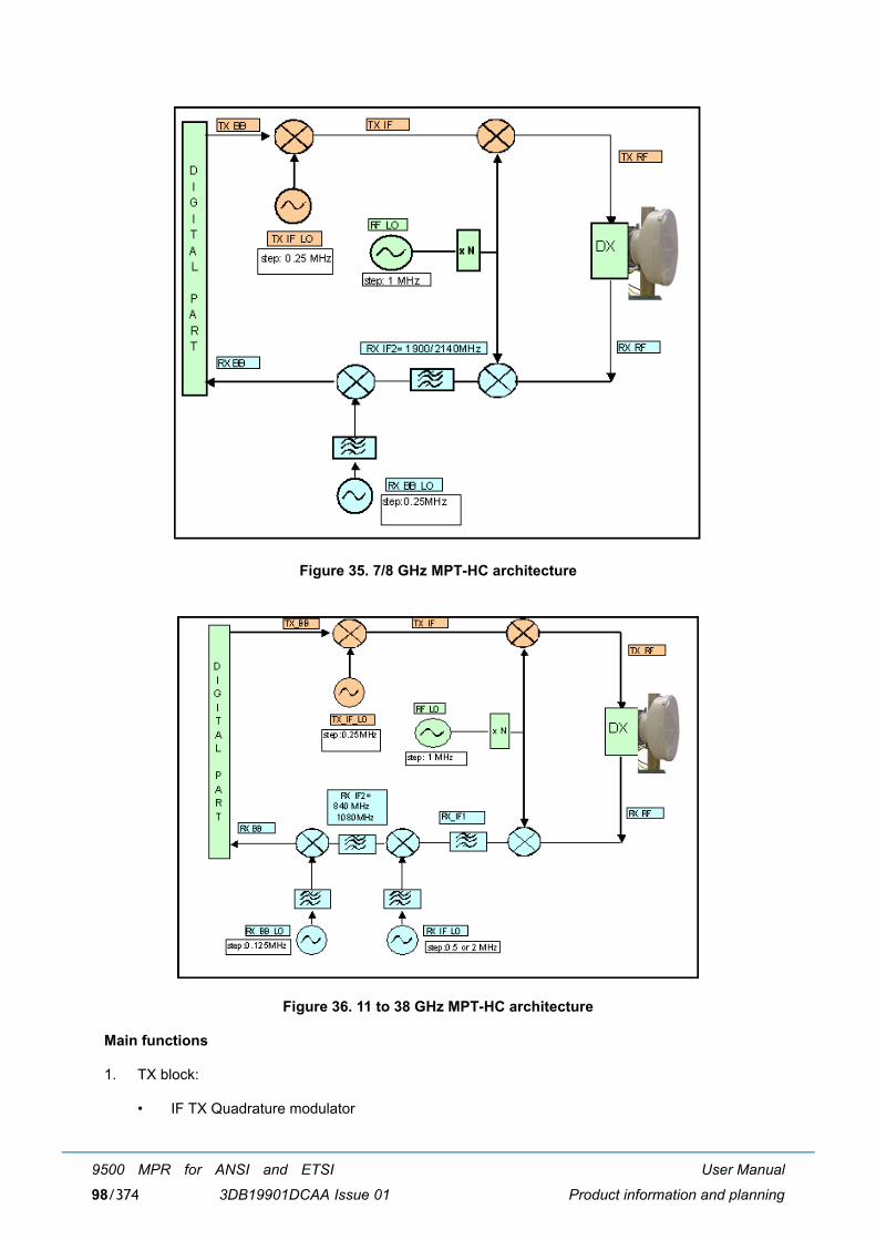
User Manual
Product information and planning
9500 MPR for ANSI and ETSI
3DB19901DCAA Issue 0198/374
Figure 35. 7/8 GHz MPT-HC architecture
Figure 36. 11 to 38 GHz MPT-HC architecture
Main functions
1. TX block:
� IF TX Quadrature modulator
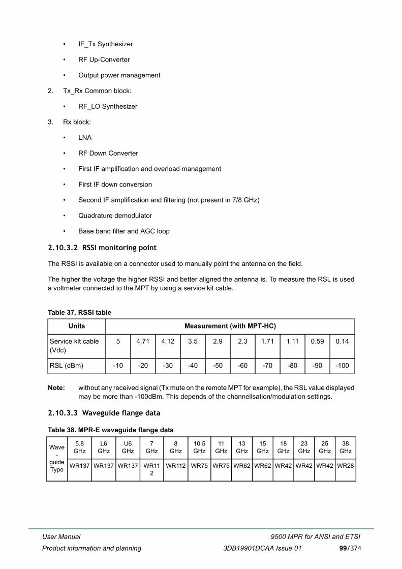
User Manual
Product information and planning
9500 MPR for ANSI and ETSI
3DB19901DCAA Issue 01 99/374
� IF_Tx Synthesizer
� RF Up-Converter
� Output power management
2. Tx_Rx Common block:
� RF_LO Synthesizer
3. Rx block:
� LNA
� RF Down Converter
� First IF amplification and overload management
� First IF down conversion
� Second IF amplification and filtering (not present in 7/8 GHz)
� Quadrature demodulator
� Base band filter and AGC loop
2.10.3.2 RSSI monitoring point
The RSSI is available on a connector used to manually point the antenna on the field.
The higher the voltage the higher RSSI and better aligned the antenna is. To measure the RSL is useda voltmeter connected to the MPT by using a service kit cable.
Table 37. RSSI table
Note: without any received signal (Tx mute on the remote MPT for example), the RSL value displayedmay be more than -100dBm. This depends of the channelisation/modulation settings.
2.10.3.3 Waveguide flange data
Table 38. MPR-E waveguide flange data
Units Measurement (with MPT-HC)
Service kit cable(Vdc)
5 4.71 4.12 3.5 2.9 2.3 1.71 1.11 0.59 0.14
RSL (dBm) -10 -20 -30 -40 -50 -60 -70 -80 -90 -100
Wave-
guide Type
5.8 GHz
L6 GHz
U6GHz
7 GHz
8 GHz
10.5GHz
11 GHz
13 GHz
15 GHz
18 GHz
23 GHz
25 GHz
38 GHz
WR137 WR137 WR137 WR112
WR112 WR75 WR75 WR62 WR62 WR42 WR42 WR42 WR28
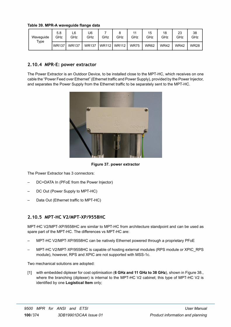
User Manual
Product information and planning
9500 MPR for ANSI and ETSI
3DB19901DCAA Issue 01100/374
Table 39. MPR-A waveguide flange data
2.10.4 MPR-E: power extractor
The Power Extractor is an Outdoor Device, to be installed close to the MPT-HC, which receives on onecable the �Power Feed over Ethernet� (Ethernet traffic and Power Supply), provided by the Power Injector,and separates the Power Supply from the Ethernet traffic to be separately sent to the MPT-HC.
Figure 37. power extractor
The Power Extractor has 3 connectors:
� DC+DATA In (PFoE from the Power Injector)
� DC Out (Power Supply to MPT-HC)
� Data Out (Ethernet traffic to MPT-HC)
2.10.5 MPT-HC V2/MPT-XP/9558HC
MPT-HC V2/MPT-XP/9558HC are similar to MPT-HC from architecture standpoint and can be used asspare part of the MPT-HC. The differences vs MPT-HC are:
� MPT-HC V2/MPT-XP/9558HC can be natively Ethernet powered through a proprietary PFoE
� MPT-HC V2/MPT-XP/9558HC is capable of hosting external modules (RPS module or XPIC_RPSmodule), however, RPS and XPIC are not supported with MSS-1c.
Two mechanical solutions are adopted:
[1] with embedded diplexer for cost optimisation (6 GHz and 11 GHz to 38 GHz), shown in Figure 38.,where the branching (diplexer) is internal to the MPT-HC V2 cabinet; this type of MPT-HC V2 isidentified by one Logistical Item only;
Waveguide Type
5.8 GHz
L6 GHz
U6GHz
7 GHz
8 GHz
11 GHz
15 GHz
18 GHz
23 GHz
38 GHz
WR137 WR137 WR137 WR112 WR112 WR75 WR62 WR42 WR42 WR28
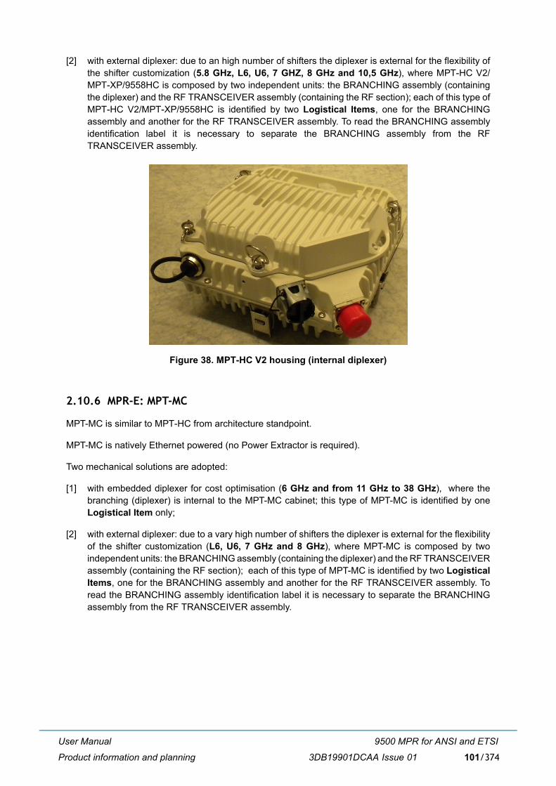
User Manual
Product information and planning
9500 MPR for ANSI and ETSI
3DB19901DCAA Issue 01 101/374
[2] with external diplexer: due to an high number of shifters the diplexer is external for the flexibility ofthe shifter customization (5.8 GHz, L6, U6, 7 GHZ, 8 GHz and 10,5 GHz), where MPT-HC V2/MPT-XP/9558HC is composed by two independent units: the BRANCHING assembly (containingthe diplexer) and the RF TRANSCEIVER assembly (containing the RF section); each of this type ofMPT-HC V2/MPT-XP/9558HC is identified by two Logistical Items, one for the BRANCHINGassembly and another for the RF TRANSCEIVER assembly. To read the BRANCHING assemblyidentification label it is necessary to separate the BRANCHING assembly from the RFTRANSCEIVER assembly.
Figure 38. MPT-HC V2 housing (internal diplexer)
2.10.6 MPR-E: MPT-MC
MPT-MC is similar to MPT-HC from architecture standpoint.
MPT-MC is natively Ethernet powered (no Power Extractor is required).
Two mechanical solutions are adopted:
[1] with embedded diplexer for cost optimisation (6 GHz and from 11 GHz to 38 GHz), where thebranching (diplexer) is internal to the MPT-MC cabinet; this type of MPT-MC is identified by oneLogistical Item only;
[2] with external diplexer: due to a vary high number of shifters the diplexer is external for the flexibilityof the shifter customization (L6, U6, 7 GHz and 8 GHz), where MPT-MC is composed by twoindependent units: the BRANCHING assembly (containing the diplexer) and the RF TRANSCEIVERassembly (containing the RF section); each of this type of MPT-MC is identified by two LogisticalItems, one for the BRANCHING assembly and another for the RF TRANSCEIVER assembly. Toread the BRANCHING assembly identification label it is necessary to separate the BRANCHINGassembly from the RF TRANSCEIVER assembly.
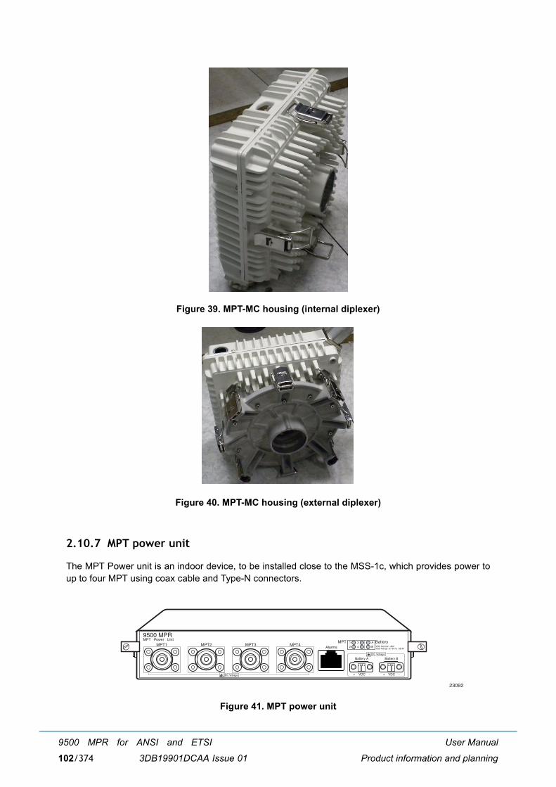
User Manual
Product information and planning
9500 MPR for ANSI and ETSI
3DB19901DCAA Issue 01102/374
Figure 39. MPT-MC housing (internal diplexer)
Figure 40. MPT-MC housing (external diplexer)
2.10.7 MPT power unit
The MPT Power unit is an indoor device, to be installed close to the MSS-1c, which provides power toup to four MPT using coax cable and Type-N connectors.
Figure 41. MPT power unit
23092
9500 MPR
MPT1MPT Power Unit
MPT2 MPT3 MPT4
DC Voltage
Alarms
Battery B
+ VDC -
VDC Normal -48VVDC Range -57.6V to -38.4V
MPT Battery1 3
2 4
A
B
Battery A
+ VDC -DC Voltage
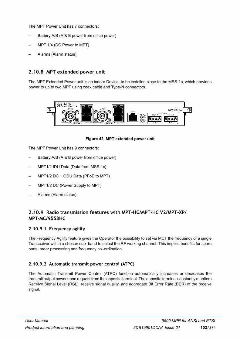
User Manual
Product information and planning
9500 MPR for ANSI and ETSI
3DB19901DCAA Issue 01 103/374
The MPT Power Unit has 7 connectors:
� Battery A/B (A & B power from office power)
� MPT 1/4 (DC Power to MPT)
� Alarms (Alarm status)
2.10.8 MPT extended power unit
The MPT Extended Power unit is an indoor Device, to be installed close to the MSS-1c, which providespower to up to two MPT using coax cable and Type-N connectors.
Figure 42. MPT extended power unit
The MPT Power Unit has 9 connectors:
� Battery A/B (A & B power from office power)
� MPT1/2 IDU Data (Data from MSS-1c)
� MPT1/2 DC + ODU Data (PFoE to MPT)
� MPT1/2 DC (Power Supply to MPT)
� Alarms (Alarm status)
2.10.9 Radio transmission features with MPT-HC/MPT-HC V2/MPT-XP/MPT-MC/9558HC
2.10.9.1 Frequency agility
The Frequency Agility feature gives the Operator the possibility to set via MCT the frequency of a singleTransceiver within a chosen sub�band to select the RF working channel. This implies benefits for spareparts, order processing and frequency co�ordination.
2.10.9.2 Automatic transmit power control (ATPC)
The Automatic Transmit Power Control (ATPC) function automatically increases or decreases thetransmit output power upon request from the opposite terminal. The opposite terminal constantly monitorsReceive Signal Level (RSL), receive signal quality, and aggregate Bit Error Rate (BER) of the receivesignal.

User Manual
Product information and planning
9500 MPR for ANSI and ETSI
3DB19901DCAA Issue 01104/374
When the ATPC is Enabled the transmit output will remain at it's lowest level until a fade occurs (or areceive circuit alarm is detected). When the change in RSL is detected at the receive end, a commandis sent to the transmit end to increase power in 1 dB steps to it's highest level. After the fade is over, thereceive end commands the transmit power to decreases in 1 dB steps to the lowest level.
The ATPC range (high and low limits) is variable, determined by link distance, link location, and linkfrequency. When ATPC Enabled is checked, the range values are shown in parenthesis (minimum -maximum) following ATPC Range.
When the ATPC is disabled the transmit output will always operate at the power value set by the MCT.
2.10.9.3 Transmitted power control: RTPC function
The capability to adjust the transmitted power in a static and fixed way (RTPC = Remote Transmit PowerControl) has been introduced for those countries where, due to internal rules, the ATPC function is notaccepted or for those hops in which due to the short length and interface problems, a fixed reducedtransmitted power is preferred. The range of the possible attenuation depends on the frequency bandinvolved. The setting of the transmitted power can be performed locally through MCT.
The Output power is band and modulation dependent.
2.10.9.4 Power monitoring
The MPT incorporates a detector for Tx power measurement. It is used to provide measurement offorward power as a performance parameter, and to provide a calibration input for transmitter operationover temperature and output range.
Viewed Tx power ranges always match the capabilities of the MPT for a given modulation. Whenmodulation is changed, the CT automatically adjusts/restricts Tx Power to be within valid range.
2.10.9.5 Adaptive equalization
Adaptive equalization (AE) is employed to improve reliability of operation under dispersive fadeconditions, typically encountered over long and difficult paths.
This is achieved through a multi-tap equalizer consisting of two registers, one with feed-forward taps, theother with feed-back taps. Each of these registers multiply successive delayed samples of the receivedsignal by weighting-coefficients to remove propagation induced inter-symbol interference.
2.10.9.6 Link identifier
The amount of microwave links, especially in urban areas presents a risk of possible interferences duringinstallation and turn-on phase.
The digital frame incorporates link identity coding capabilities to prevent the capture of an unwantedsignal.
In case of �Link Identifier Mismatch� all the traffic is dropped.
The Link identifier management can be enabled or disabled by the management systems.
2.10.9.7 Loopbacks
To facilitate the installation/commissioning and the remote maintenance two loopbacks are available.
As the activation of a loopback affects the traffic, the presence of a loopback is indicated to themanagement systems as an abnormal condition.
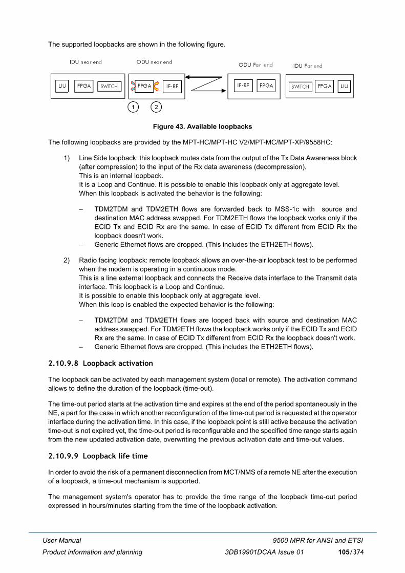
User Manual
Product information and planning
9500 MPR for ANSI and ETSI
3DB19901DCAA Issue 01 105/374
The supported loopbacks are shown in the following figure.
Figure 43. Available loopbacks
The following loopbacks are provided by the MPT-HC/MPT-HC V2/MPT-MC/MPT-XP/9558HC:
1) Line Side loopback: this loopback routes data from the output of the Tx Data Awareness block(after compression) to the input of the Rx data awareness (decompression). This is an internal loopback. It is a Loop and Continue. It is possible to enable this loopback only at aggregate level. When this loopback is activated the behavior is the following:
� TDM2TDM and TDM2ETH flows are forwarded back to MSS-1c with source anddestination MAC address swapped. For TDM2ETH flows the loopback works only if theECID Tx and ECID Rx are the same. In case of ECID Tx different from ECID Rx theloopback doesn't work.
� Generic Ethernet flows are dropped. (This includes the ETH2ETH flows).
2) Radio facing loopback: remote loopback allows an over-the-air loopback test to be performedwhen the modem is operating in a continuous mode. This is a line external loopback and connects the Receive data interface to the Transmit datainterface. This loopback is a Loop and Continue. It is possible to enable this loopback only at aggregate level. When this loop is enabled the expected behavior is the following:
� TDM2TDM and TDM2ETH flows are looped back with source and destination MACaddress swapped. For TDM2ETH flows the loopback works only if the ECID Tx and ECIDRx are the same. In case of ECID Tx different from ECID Rx the loopback doesn't work.
� Generic Ethernet flows are dropped. (This includes the ETH2ETH flows).
2.10.9.8 Loopback activation
The loopback can be activated by each management system (local or remote). The activation commandallows to define the duration of the loopback (time-out).
The time-out period starts at the activation time and expires at the end of the period spontaneously in theNE, a part for the case in which another reconfiguration of the time-out period is requested at the operatorinterface during the activation time. In this case, if the loopback point is still active because the activationtime-out is not expired yet, the time-out period is reconfigurable and the specified time range starts againfrom the new updated activation date, overwriting the previous activation date and time-out values.
2.10.9.9 Loopback life time
In order to avoid the risk of a permanent disconnection from MCT/NMS of a remote NE after the executionof a loopback, a time-out mechanism is supported.
The management system's operator has to provide the time range of the loopback time-out periodexpressed in hours/minutes starting from the time of the loopback activation.
User Manual
Product information and planning
9500 MPR for ANSI and ETSI
3DB19901DCAA Issue 01106/374
A default time-out period may be suggested at the operator interface, even if it could be modified on user-needs basis.
After the NE reset, the activation of each loopback point is lost and must be recreated again if needed,starting with a new time-out period.
2.10.9.10 Unlicensed radio for 9558HC
The JF6-9558HC/6933B-9558HC (9558HC) unlicensed radio provide fast deployment of service withmicrowave radio. No license and small antennas (no FCC and Industry Canada (IC) requirements) allowimmediate Turn-Up. The 9558HC unlicensed radio can not be upgraded to licensed.
Note: Changes or modifications not expressly approved by Alcatel-Lucent could void the authority tooperate the JF6-9558HC/6933B-9558HC unlicensed radio.
Note: Installation, Turn-Up, Maintenance, and Operation Instruction supplied with the JF6-9558HC/6933B-9558HC unlicensed radio require strict adherence for continued part 15 of the FCCRules and IC RSS-210 compliance.
Table 40. Unlicensed radio
See the Equipping Options Drawing for unlicensed radio configurations and equipping options, found inthe 9500 MPR-A Engineering Support Documentation manual (PN 3EM23957AM).
The 9558HC unlicensed radio operate in the 5725-5850 Information, Scientific, and Medical (ISM) bandin accordance with FCC Part 15.247 and IC RSS-210. This unlicensed radio, although operating in thesame band as a spread spectrum radio, operates using narrower bandwidths than spread spectrum.Advantages, disadvantages, and antenna recommendations for the unlicensed radio follow:
Advantages:
� Fast installation and Turn-Up
� Between 6.6 � 185 Mb/s user configurable data payload capacity consisting of a combination ofDS1, DS3, and/or Ethernet traffic
� Field expandable to higher capacities.
� Common network management with licensed radios.
� Common spares and training with licensed radios
� Adaptive Modulation - automatic interference countermeasures
Disadvantages:
� Interference from other 5725-5850 ISM band transmissions are possible
� Operating restrictions
� 5.725 to 5.850 GHz band
� Performance could deteriorate due to interference as the frequency band becomes congested.
Transceiver FCC ID Industry Canada ID
9558HC JF6-9558HC 6933B-9558HC

User Manual
Product information and planning
9500 MPR for ANSI and ETSI
3DB19901DCAA Issue 01 107/374
Antenna recommendations:
� Frequency � 5.8 GHz
� Size and Type � 2, 4, 6, 8, or 10 foot parabolic; 1 or 2 foot flat panel.
� Parabolic antennas, See Table 41.
� Flat antennas, See Table 41.
� Gain and 3 dB Beamwidth
This device has been designed to operate with the antennas listed below, and having a maximum gainof 42.5 dB. Antennas not included in this list or having a gain greater than 42.5 dB are strictly prohibitedfor use with this device. The required antenna impedance is 50 ohms.
These antennas can only be used in a fixed point-to-point configuration.
To reduce potential radio interference to other users, the antenna type and its gain should be so chosenthat the equivalent isotropically radiated power (e.i.r.p) is not more than that permitted for successfulcommunication.
The antenna(s) used for this transmitter must be installed to provide a separation distance of at least 12meters from all persons and must not be co-located or operating in conjunction with any other antennaor transmitter.
Note: DANGER: Danger of public exposure to long term RF radiated energy. When using a 1 ft flatpanel antenna with a 1 watt (+30 dBm) output power, the antenna must be located in an areathat does not allow the general population access to within 12 meters (5.8 Ghz) of the antenna.
Frequency Plan: For 9558HC frequency plan for the 5.725 and 5.850 GHz unlicensed band, refer toFigure 30.
Output Power: A requirement of operating in the unlicensed band is to limit transmit output power to notmore than +30.0 dBm at the antenna port. It is the responsibility of the user to transmit not more than+30.0 dBm.
Note: To meet FCC part 15 requirements, output power for MPT-HC 30 MHz 4QAM and 8QAMchannels must not be provisioned greater than 24 dBm. This is not enforced by the userinterface and is the responsibility of the operator to guarantee provisioning of the radio transmitpower. For transmit power specification, see the System Application Rules document, found inthe 9500 MPR-A Engineering Support Documentation manual (PN 3EM23957AM).
Table 41. 5.8 GHz unlicensed antenna optionsPARABOLIC FLAT
9558HC 9558HC2 ft parabolic � 29 dB/6° 1 ft flat panel � 23 dB/9°4 ft parabolic � 35 dB/3° 2 ft flat panel � 28 dB/3.5°6 ft parabolic � 38 dB/2° �
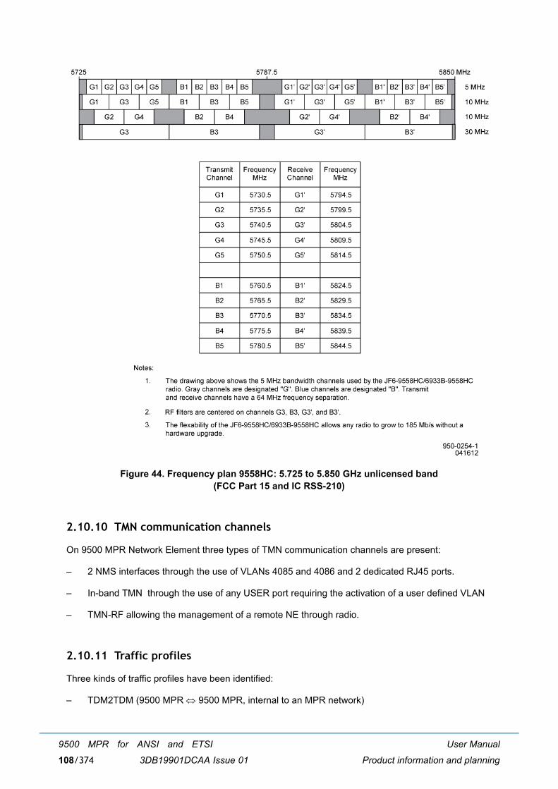
User Manual
Product information and planning
9500 MPR for ANSI and ETSI
3DB19901DCAA Issue 01108/374
Figure 44. Frequency plan 9558HC: 5.725 to 5.850 GHz unlicensed band(FCC Part 15 and IC RSS-210)
2.10.10 TMN communication channels
On 9500 MPR Network Element three types of TMN communication channels are present:
� 2 NMS interfaces through the use of VLANs 4085 and 4086 and 2 dedicated RJ45 ports.
� In-band TMN through the use of any USER port requiring the activation of a user defined VLAN
� TMN-RF allowing the management of a remote NE through radio.
2.10.11 Traffic profiles
Three kinds of traffic profiles have been identified:
� TDM2TDM (9500 MPR ⇔ 9500 MPR, internal to an MPR network)
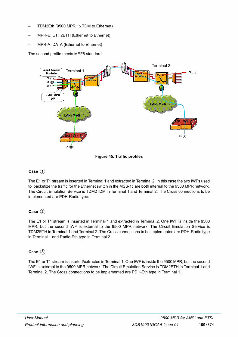
User Manual
Product information and planning
9500 MPR for ANSI and ETSI
3DB19901DCAA Issue 01 109/374
� TDM2Eth (9500 MPR ⇔ TDM to Ethernet)
� MPR-E: ETH2ETH (Ethernet to Ethernet)
� MPR-A: DATA (Ethernet to Ethernet)
The second profile meets MEF8 standard.
Figure 45. Traffic profiles
The E1 or T1 stream is inserted in Terminal 1 and extracted in Terminal 2. In this case the two IWFs usedto packetize the traffic for the Ethernet switch in the MSS-1c are both internal to the 9500 MPR network.The Circuit Emulation Service is TDM2TDM in Terminal 1 and Terminal 2. The Cross connections to beimplemented are PDH-Radio type.
The E1 or T1 stream is inserted in Terminal 1 and extracted in Terminal 2. One IWF is inside the 9500MPR, but the second IWF is external to the 9500 MPR network. The Circuit Emulation Service isTDM2ETH in Terminal 1 and Terminal 2. The Cross connections to be implemented are PDH-Radio typein Terminal 1 and Radio-Eth type in Terminal 2.
The E1 or T1 stream is inserted/extracted in Terminal 1. One IWF is inside the 9500 MPR, but the secondIWF is external to the 9500 MPR network. The Circuit Emulation Service is TDM2ETH in Terminal 1 andTerminal 2. The Cross connections to be implemented are PDH-Eth type in Terminal 1.
Terminal 1Terminal 2
Case 1
Case 2
Case 3
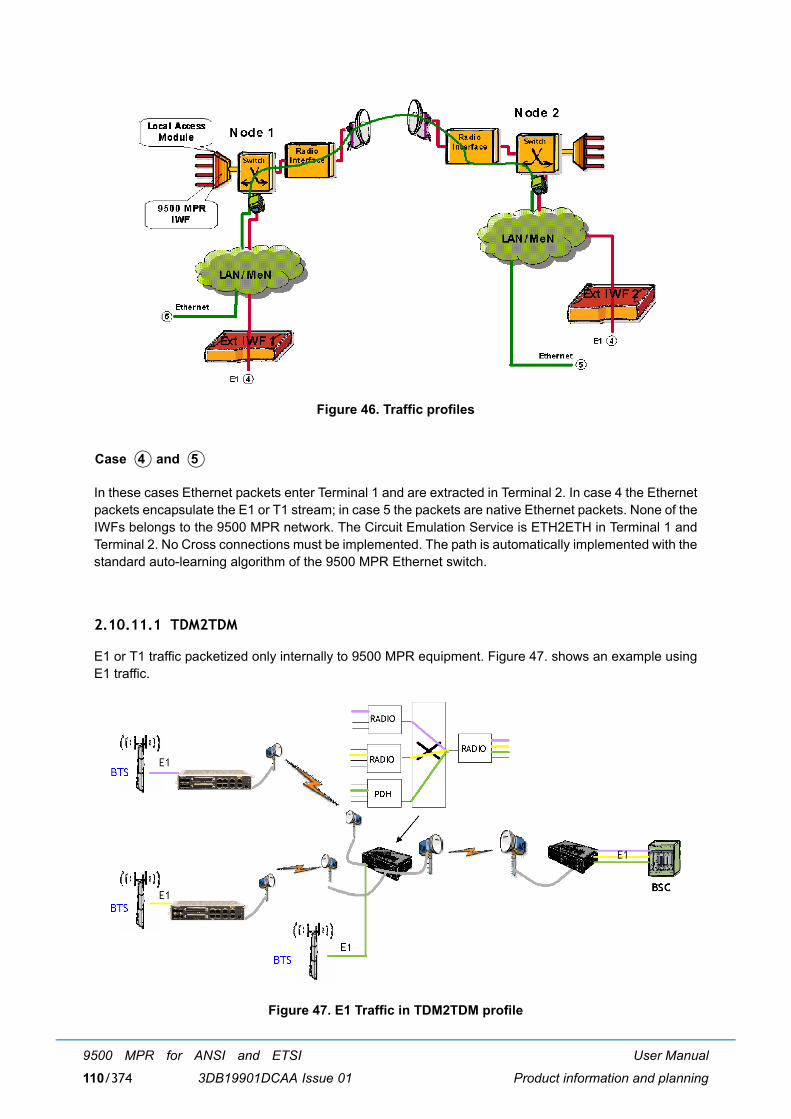
User Manual
Product information and planning
9500 MPR for ANSI and ETSI
3DB19901DCAA Issue 01110/374
Figure 46. Traffic profiles
In these cases Ethernet packets enter Terminal 1 and are extracted in Terminal 2. In case 4 the Ethernetpackets encapsulate the E1 or T1 stream; in case 5 the packets are native Ethernet packets. None of theIWFs belongs to the 9500 MPR network. The Circuit Emulation Service is ETH2ETH in Terminal 1 andTerminal 2. No Cross connections must be implemented. The path is automatically implemented with thestandard auto-learning algorithm of the 9500 MPR Ethernet switch.
2.10.11.1 TDM2TDM
E1 or T1 traffic packetized only internally to 9500 MPR equipment. Figure 47. shows an example usingE1 traffic.
Figure 47. E1 Traffic in TDM2TDM profile
Case 4 and 5
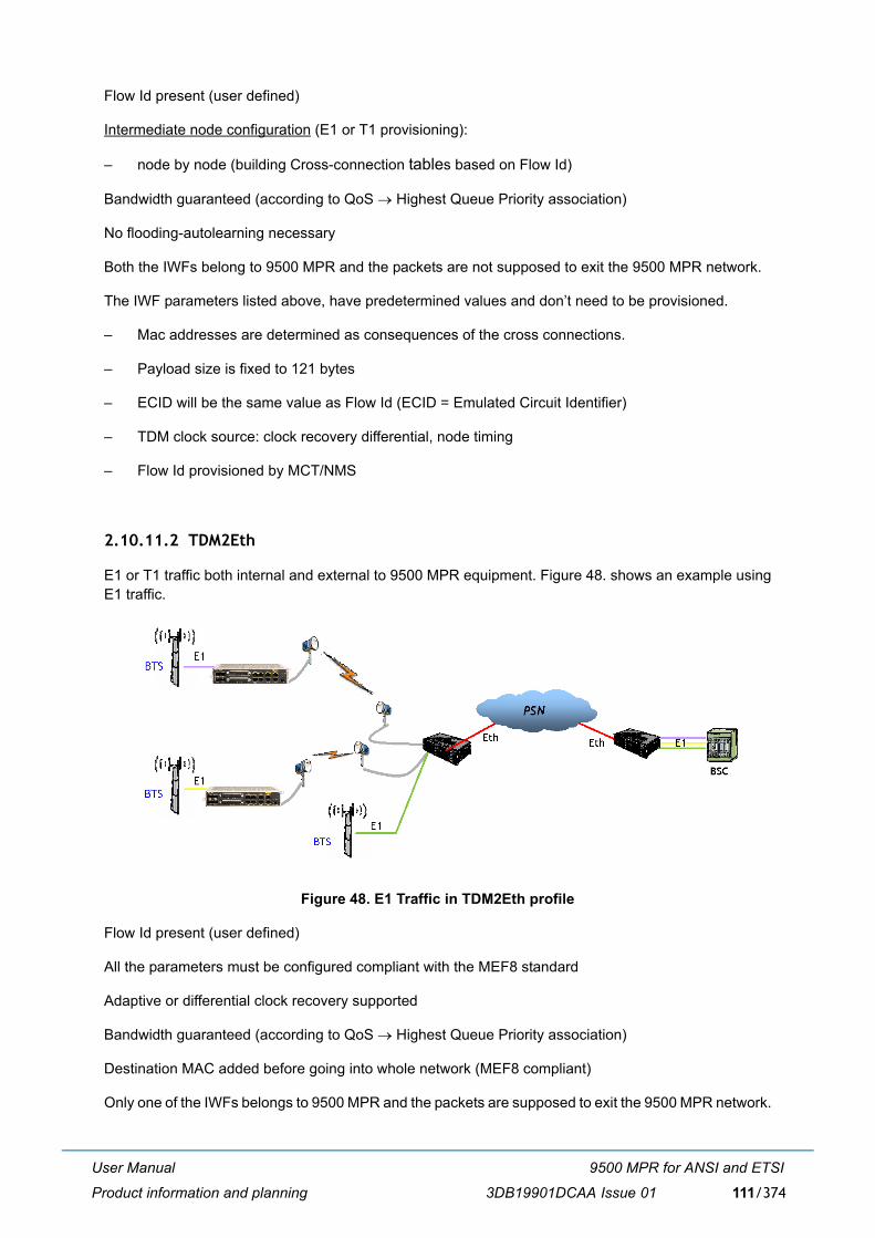
User Manual
Product information and planning
9500 MPR for ANSI and ETSI
3DB19901DCAA Issue 01 111/374
Flow Id present (user defined)
Intermediate node configuration (E1 or T1 provisioning):
� node by node (building Cross-connection tables based on Flow Id)
Bandwidth guaranteed (according to QoS → Highest Queue Priority association)
No flooding-autolearning necessary
Both the IWFs belong to 9500 MPR and the packets are not supposed to exit the 9500 MPR network.
The IWF parameters listed above, have predetermined values and don�t need to be provisioned.
� Mac addresses are determined as consequences of the cross connections.
� Payload size is fixed to 121 bytes
� ECID will be the same value as Flow Id (ECID = Emulated Circuit Identifier)
� TDM clock source: clock recovery differential, node timing
� Flow Id provisioned by MCT/NMS
2.10.11.2 TDM2Eth
E1 or T1 traffic both internal and external to 9500 MPR equipment. Figure 48. shows an example usingE1 traffic.
Figure 48. E1 Traffic in TDM2Eth profile
Flow Id present (user defined)
All the parameters must be configured compliant with the MEF8 standard
Adaptive or differential clock recovery supported
Bandwidth guaranteed (according to QoS → Highest Queue Priority association)
Destination MAC added before going into whole network (MEF8 compliant)
Only one of the IWFs belongs to 9500 MPR and the packets are supposed to exit the 9500 MPR network.
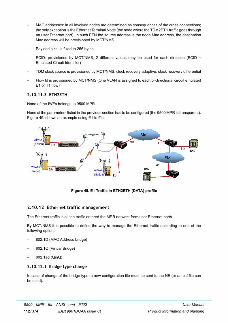
User Manual
Product information and planning
9500 MPR for ANSI and ETSI
3DB19901DCAA Issue 01112/374
� MAC addresses: in all involved nodes are determined as consequences of the cross connections;the only exception is the Ethernet Terminal Node (the node where the TDM2ETH traffic goes throughan user Ethernet port). In such ETN the source address is the node Mac address, the destinationMac address will be provisioned by MCT/NMS.
� Payload size: is fixed to 256 bytes
� ECID: provisioned by MCT/NMS, 2 different values may be used for each direction (ECID =Emulated Circuit Identifier)
� TDM clock source is provisioned by MCT/NMS: clock recovery adaptive, clock recovery differential
� Flow Id is provisioned by MCT/NMS (One VLAN is assigned to each bi-directional circuit emulatedE1 or T1 flow)
2.10.11.3 ETH2ETH
None of the IWFs belongs to 9500 MPR.
None of the parameters listed in the previous section has to be configured (the 9500 MPR is transparent).Figure 49. shows an example using E1 traffic.
Figure 49. E1 Traffic in ETH2ETH (DATA) profile
2.10.12 Ethernet traffic management
The Ethernet traffic is all the traffic entered the MPR network from user Ethernet ports.
By MCT/NMS it is possible to define the way to manage the Ethernet traffic according to one of thefollowing options:
� 802.1D (MAC Address bridge)
� 802.1Q (Virtual Bridge)
� 802.1ad (QinQ)
2.10.12.1 Bridge type change
In case of change of the bridge type, a new configuration file must be sent to the NE (or an old file canbe used).
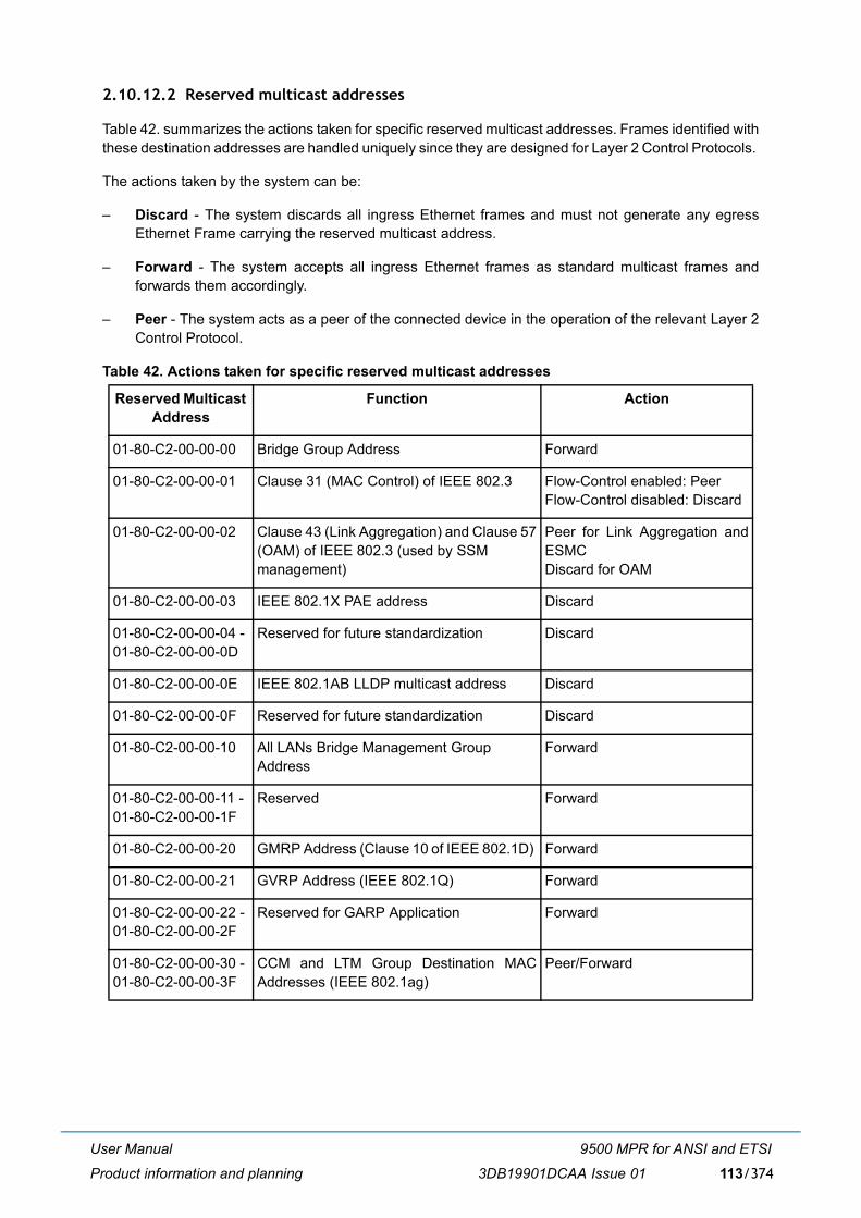
User Manual
Product information and planning
9500 MPR for ANSI and ETSI
3DB19901DCAA Issue 01 113/374
2.10.12.2 Reserved multicast addresses
Table 42. summarizes the actions taken for specific reserved multicast addresses. Frames identified withthese destination addresses are handled uniquely since they are designed for Layer 2 Control Protocols.
The actions taken by the system can be:
� Discard - The system discards all ingress Ethernet frames and must not generate any egressEthernet Frame carrying the reserved multicast address.
� Forward - The system accepts all ingress Ethernet frames as standard multicast frames andforwards them accordingly.
� Peer - The system acts as a peer of the connected device in the operation of the relevant Layer 2Control Protocol.
Table 42. Actions taken for specific reserved multicast addresses
Reserved Multicast Address
Function Action
01-80-C2-00-00-00 Bridge Group Address Forward
01-80-C2-00-00-01 Clause 31 (MAC Control) of IEEE 802.3 Flow-Control enabled: PeerFlow-Control disabled: Discard
01-80-C2-00-00-02 Clause 43 (Link Aggregation) and Clause 57(OAM) of IEEE 802.3 (used by SSM management)
Peer for Link Aggregation andESMCDiscard for OAM
01-80-C2-00-00-03 IEEE 802.1X PAE address Discard
01-80-C2-00-00-04 - 01-80-C2-00-00-0D
Reserved for future standardization Discard
01-80-C2-00-00-0E IEEE 802.1AB LLDP multicast address Discard
01-80-C2-00-00-0F Reserved for future standardization Discard
01-80-C2-00-00-10 All LANs Bridge Management GroupAddress
Forward
01-80-C2-00-00-11 - 01-80-C2-00-00-1F
Reserved Forward
01-80-C2-00-00-20 GMRP Address (Clause 10 of IEEE 802.1D) Forward
01-80-C2-00-00-21 GVRP Address (IEEE 802.1Q) Forward
01-80-C2-00-00-22 - 01-80-C2-00-00-2F
Reserved for GARP Application Forward
01-80-C2-00-00-30 - 01-80-C2-00-00-3F
CCM and LTM Group Destination MACAddresses (IEEE 802.1ag)
Peer/Forward
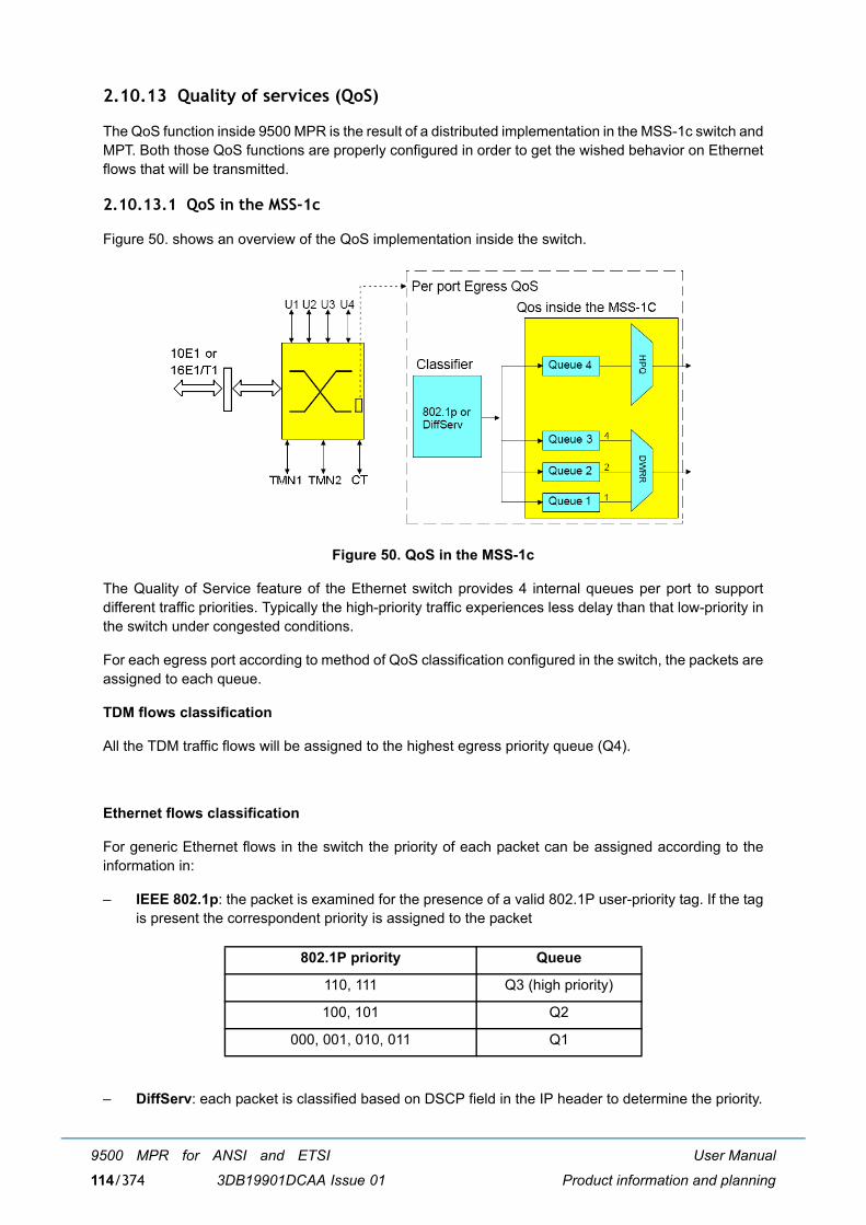
User Manual
Product information and planning
9500 MPR for ANSI and ETSI
3DB19901DCAA Issue 01114/374
2.10.13 Quality of services (QoS)
The QoS function inside 9500 MPR is the result of a distributed implementation in the MSS-1c switch andMPT. Both those QoS functions are properly configured in order to get the wished behavior on Ethernetflows that will be transmitted.
2.10.13.1 QoS in the MSS-1c
Figure 50. shows an overview of the QoS implementation inside the switch.
Figure 50. QoS in the MSS-1c
The Quality of Service feature of the Ethernet switch provides 4 internal queues per port to supportdifferent traffic priorities. Typically the high-priority traffic experiences less delay than that low-priority inthe switch under congested conditions.
For each egress port according to method of QoS classification configured in the switch, the packets areassigned to each queue.
TDM flows classification
All the TDM traffic flows will be assigned to the highest egress priority queue (Q4).
Ethernet flows classification
For generic Ethernet flows in the switch the priority of each packet can be assigned according to theinformation in:
� IEEE 802.1p: the packet is examined for the presence of a valid 802.1P user-priority tag. If the tagis present the correspondent priority is assigned to the packet
� DiffServ: each packet is classified based on DSCP field in the IP header to determine the priority.
802.1P priority Queue
110, 111 Q3 (high priority)
100, 101 Q2
000, 001, 010, 011 Q1
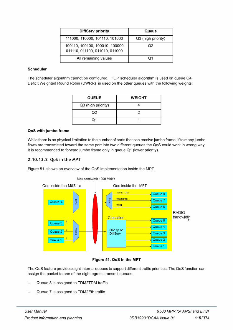
User Manual
Product information and planning
9500 MPR for ANSI and ETSI
3DB19901DCAA Issue 01 115/374
Scheduler
The scheduler algorithm cannot be configured. HQP scheduler algorithm is used on queue Q4. Deficit Weighted Round Robin (DWRR) is used on the other queues with the following weights:
QoS with jumbo frame
While there is no physical limitation to the number of ports that can receive jumbo frame, if to many jumboflows are transmitted toward the same port into two different queues the QoS could work in wrong way.It is recommended to forward jumbo frame only in queue Q1 (lower priority).
2.10.13.2 QoS in the MPT
Figure 51. shows an overview of the QoS implementation inside the MPT.
Figure 51. QoS in the MPT
The QoS feature provides eight internal queues to support different traffic priorities. The QoS function canassign the packet to one of the eight egress transmit queues.
� Queue 8 is assigned to TDM2TDM traffic
� Queue 7 is assigned to TDM2Eth traffic
DiffServ priority Queue
111000, 110000, 101110, 101000 Q3 (high priority)
100110, 100100, 100010, 100000011110, 011100, 011010, 011000
Q2
All remaining values Q1
QUEUE WEIGHT
Q3 (high priority) 4
Q2 2
Q1 1
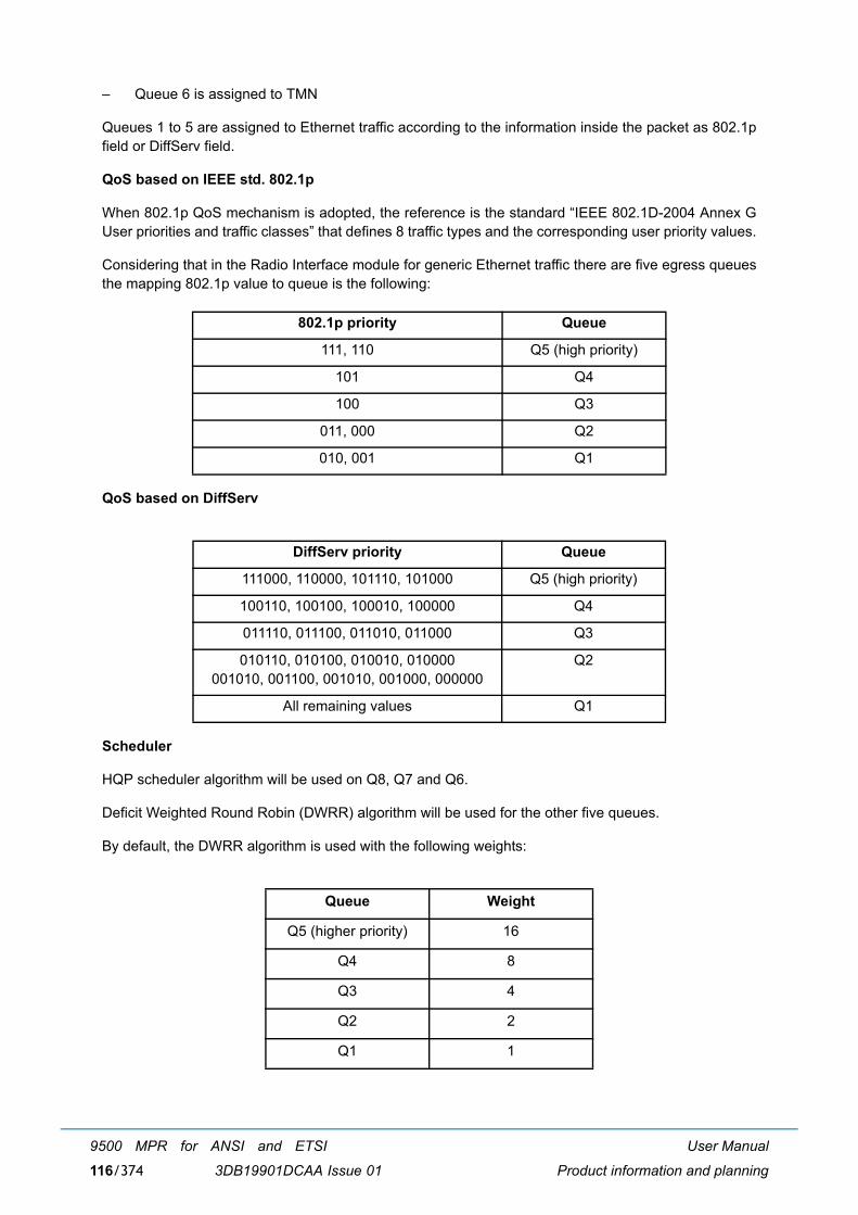
User Manual
Product information and planning
9500 MPR for ANSI and ETSI
3DB19901DCAA Issue 01116/374
� Queue 6 is assigned to TMN
Queues 1 to 5 are assigned to Ethernet traffic according to the information inside the packet as 802.1pfield or DiffServ field.
QoS based on IEEE std. 802.1p
When 802.1p QoS mechanism is adopted, the reference is the standard �IEEE 802.1D-2004 Annex GUser priorities and traffic classes� that defines 8 traffic types and the corresponding user priority values.
Considering that in the Radio Interface module for generic Ethernet traffic there are five egress queuesthe mapping 802.1p value to queue is the following:
QoS based on DiffServ
Scheduler
HQP scheduler algorithm will be used on Q8, Q7 and Q6.
Deficit Weighted Round Robin (DWRR) algorithm will be used for the other five queues.
By default, the DWRR algorithm is used with the following weights:
802.1p priority Queue
111, 110 Q5 (high priority)
101 Q4
100 Q3
011, 000 Q2
010, 001 Q1
DiffServ priority Queue
111000, 110000, 101110, 101000 Q5 (high priority)
100110, 100100, 100010, 100000 Q4
011110, 011100, 011010, 011000 Q3
010110, 010100, 010010, 010000001010, 001100, 001010, 001000, 000000
Q2
All remaining values Q1
Queue Weight
Q5 (higher priority) 16
Q4 8
Q3 4
Q2 2
Q1 1
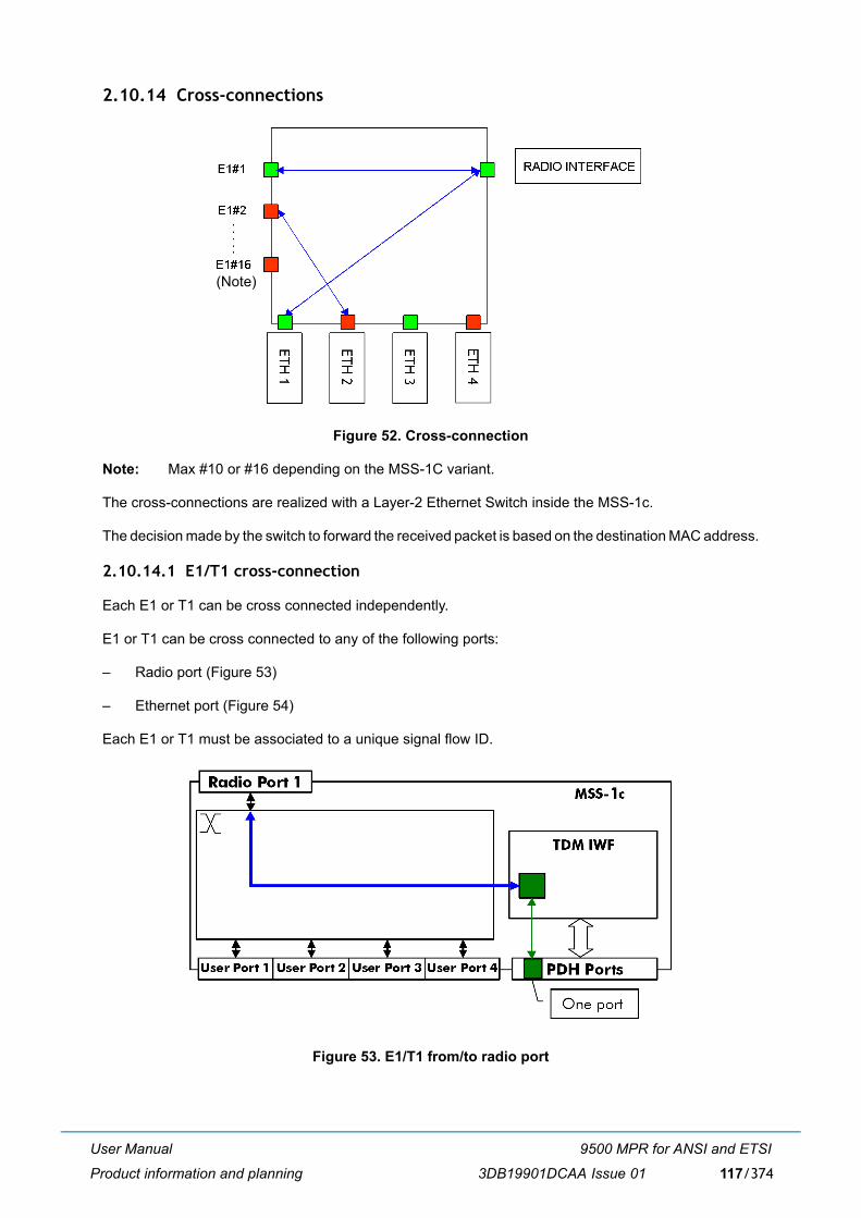
User Manual
Product information and planning
9500 MPR for ANSI and ETSI
3DB19901DCAA Issue 01 117/374
2.10.14 Cross-connections
Figure 52. Cross-connection
Note: Max #10 or #16 depending on the MSS-1C variant.
The cross-connections are realized with a Layer-2 Ethernet Switch inside the MSS-1c.
The decision made by the switch to forward the received packet is based on the destination MAC address.
2.10.14.1 E1/T1 cross-connection
Each E1 or T1 can be cross connected independently.
E1 or T1 can be cross connected to any of the following ports:
� Radio port (Figure 53)
� Ethernet port (Figure 54)
Each E1 or T1 must be associated to a unique signal flow ID.
Figure 53. E1/T1 from/to radio port
(Note)
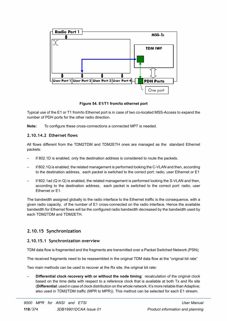
User Manual
Product information and planning
9500 MPR for ANSI and ETSI
3DB19901DCAA Issue 01118/374
Figure 54. E1/T1 from/to ethernet port
Typical use of the E1 or T1 from/to Ethernet port is in case of two co-located MSS-Access to expand thenumber of PDH ports for the other radio direction.
Note: To configure these cross-connections a connected MPT is needed.
2.10.14.2 Ethernet flows
All flows different from the TDM2TDM and TDM2ETH ones are managed as the standard Ethernetpackets:
� if 802.1D is enabled, only the destination address is considered to route the packets.
� if 802.1Q is enabled, the related management is performed looking the C-VLAN and then, accordingto the destination address, each packet is switched to the correct port: radio, user Ethernet or E1
� if 802.1ad (Q in Q) is enabled, the related management is performed looking the S-VLAN and then,according to the destination address, each packet is switched to the correct port: radio, userEthernet or E1.
The bandwidth assigned globally to the radio interface to the Ethernet traffic is the consequence, with agiven radio capacity, of the number of E1 cross-connected on the radio interface. Hence the availablebandwidth for Ethernet flows will be the configured radio bandwidth decreased by the bandwidth used byeach TDM2TDM and TDM2ETH.
2.10.15 Synchronization
2.10.15.1 Synchronization overview
TDM data flow is fragmented and the fragments are transmitted over a Packet Switched Network (PSN);
The received fragments need to be reassembled in the original TDM data flow at the �original bit rate�
Two main methods can be used to recover at the Rx site, the original bit rate:
� Differential clock recovery with or without the node timing: recalculation of the original clockbased on the time delta with respect to a reference clock that is available at both Tx and Rx site(Differential: used in case of clock distribution on the whole network. It�s more reliable than Adaptive;also used in TDM2TDM traffic (MPR to MPR)). This method can be selected for each E1 stream.
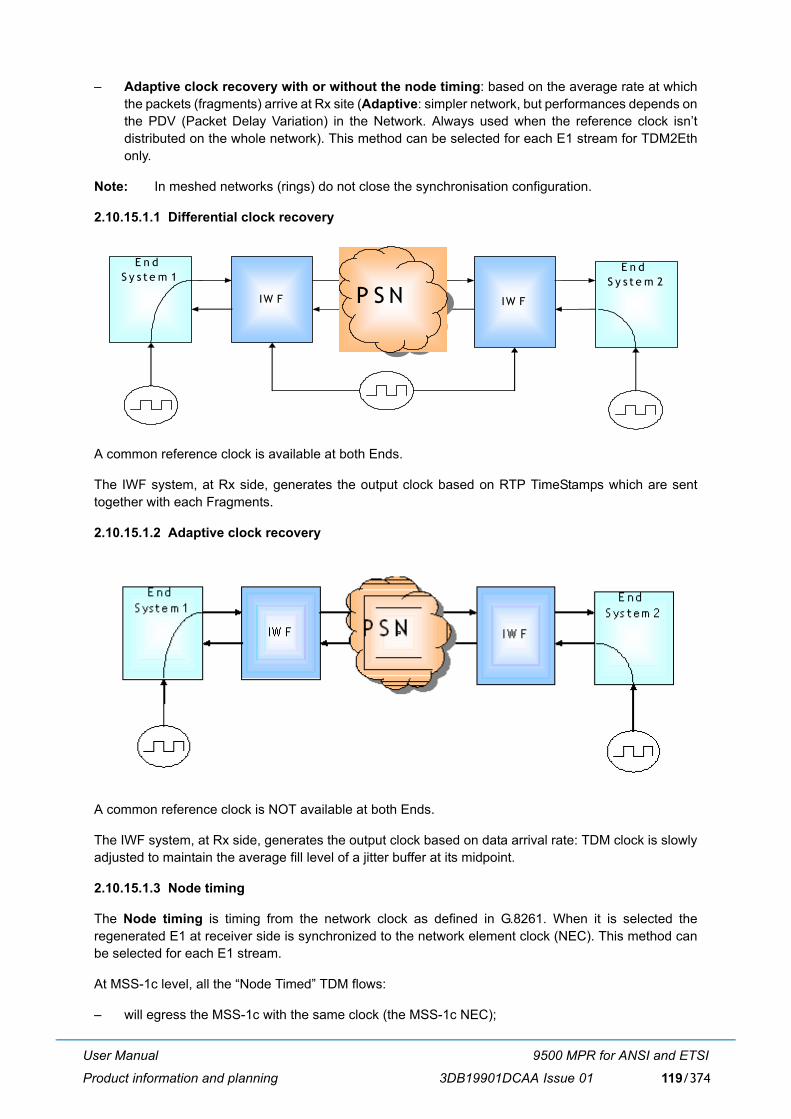
User Manual
Product information and planning
9500 MPR for ANSI and ETSI
3DB19901DCAA Issue 01 119/374
� Adaptive clock recovery with or without the node timing: based on the average rate at whichthe packets (fragments) arrive at Rx site (Adaptive: simpler network, but performances depends onthe PDV (Packet Delay Variation) in the Network. Always used when the reference clock isn�tdistributed on the whole network). This method can be selected for each E1 stream for TDM2Ethonly.
Note: In meshed networks (rings) do not close the synchronisation configuration.
2.10.15.1.1 Differential clock recovery
A common reference clock is available at both Ends.
The IWF system, at Rx side, generates the output clock based on RTP TimeStamps which are senttogether with each Fragments.
2.10.15.1.2 Adaptive clock recovery
A common reference clock is NOT available at both Ends.
The IWF system, at Rx side, generates the output clock based on data arrival rate: TDM clock is slowlyadjusted to maintain the average fill level of a jitter buffer at its midpoint.
2.10.15.1.3 Node timing
The Node timing is timing from the network clock as defined in G.8261. When it is selected theregenerated E1 at receiver side is synchronized to the network element clock (NEC). This method canbe selected for each E1 stream.
At MSS-1c level, all the �Node Timed� TDM flows:
� will egress the MSS-1c with the same clock (the MSS-1c NEC);
E n d S y s t e m 1
IW F IW F
E n d S y s t e m 2
P S NP S N

User Manual
Product information and planning
9500 MPR for ANSI and ETSI
3DB19901DCAA Issue 01120/374
� MUST ingress the MSS-1c being synchronised by the same clock.
As for any synchronisation clock transmission, the user shall particularly take care to avoidsynchronisation loop and TDM traffic hits:
� or the MSS-1c is the master clock and the external equipment must recover its own clock from oneof the �node timed� TDM flows and use this recovered clock to generate its TDM flows;
� or the external equipment is the master clock (i.e. it generates all its TDM flows by using its internalclock) and the MSS-1c MUST use one of the �node timed� ingressing TDM flows as clock sourcefor its NEC;
� or both of the MSS-1c and external equipment MUST be synchronised by the same clock if this clockcomes from another equipment.
2.10.15.2 Synchronization interface
Each Network Element must have a reference clock (NEC), which will be distributed to each circuit of theNE. Such clock is a 25 MHz generated in the MSS-1c in the Clock Reference Unit (CRU) function.
The NEC is locked to a Synchronization Source.
The sources can be:
[1] Internal Local Oscillator. It is the clock provided by the Local Oscillator inside the NE
[2] Any E1/T1 available at input traffic interfaces (the specific E1/T1 port has to be chosen)
[3] The Symbol Rate of the Rx signal of the Radio direction
[4] SynchE: Any Synchronous Ethernet clock source available at enabled User Ethernet trafficinterfaces (both electrical and optical), configured in synchronous operation mode (the UserEthernet ports, SynchE compatible, are given in paragraph 2.10.1.6 on page 92). From ITU-T G.8264point of view, the MSS is a Synchronous Ethernet equipment equipped with a system clock (NEC). A User Ethernet interface configured in synchronous operation mode can work only at 1 Giga. In theparticular case of electrical User Ethernet interfaces, these interfaces perform link auto negotiationto determine the master and slave clocks for the link. The clock slave role must be configured as partof auto negotiation parameters in order to use the interface as Synchronous Ethernet clock source.
Some rules have to be followed while configuring the Primary and Secondary clock sources.
All the NECs have to be configured as Master or Slave.
Only one Master is allowed in the network.
� If Master,
� The Restoration Mode can be Revertive or Not Revertive. If the mode is Revertive, when afailed source becomes available, the switch goes back.
� The Primary sources must be choosen among 1), 2) or 4).
� depending on master primary selection, the Master Secondary Source must be selectedamong 1), 2) or 4).
� If Slave,
� The Restoration Mode is fixed to Revertive.

User Manual
Product information and planning
9500 MPR for ANSI and ETSI
3DB19901DCAA Issue 01 121/374
� The Primary Source must be choosen between 3) or 4)
� The Secondary Source can be choosen among 1), 2) or 4).
For each available sync source, the CRU detects the signal Degrade Alarm on each available syncsource. Such Signal Degrade alarm raises also in case of muted (missing) clock.
The Signal Degraded Alarm relevant to the selected Synchronization Source, or the relevant circuit Fail,causes the switching of the Synchronization Source.

User Manual
Product information and planning
9500 MPR for ANSI and ETSI
3DB19901DCAA Issue 01122/374
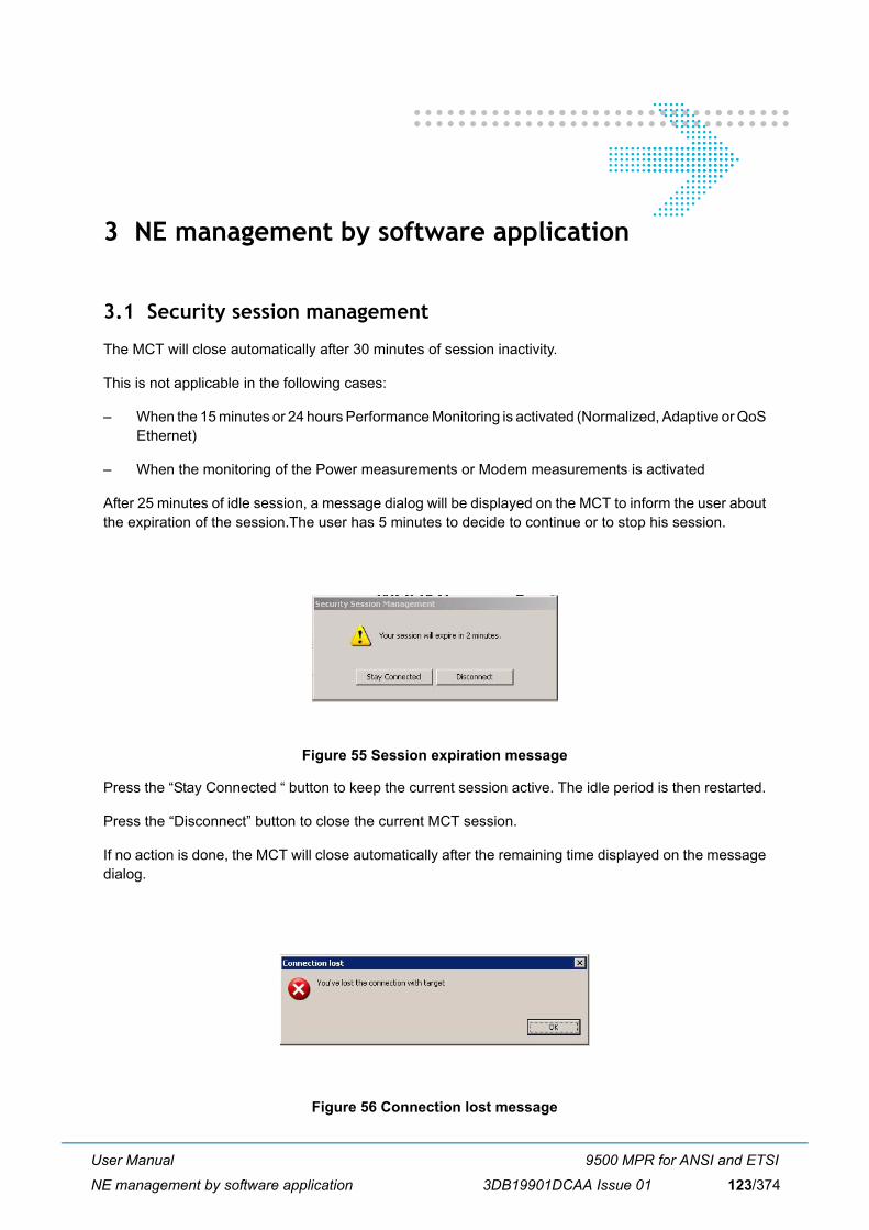
User Manual
NE management by software application
9500 MPR for ANSI and ETSI
3DB19901DCAA Issue 01 123/374
3 NE management by software application
3.1 Security session management
The MCT will close automatically after 30 minutes of session inactivity.
This is not applicable in the following cases:
� When the 15 minutes or 24 hours Performance Monitoring is activated (Normalized, Adaptive or QoSEthernet)
� When the monitoring of the Power measurements or Modem measurements is activated
After 25 minutes of idle session, a message dialog will be displayed on the MCT to inform the user aboutthe expiration of the session.The user has 5 minutes to decide to continue or to stop his session.
Figure 55 Session expiration message
Press the �Stay Connected � button to keep the current session active. The idle period is then restarted.
Press the �Disconnect� button to close the current MCT session.
If no action is done, the MCT will close automatically after the remaining time displayed on the messagedialog.
Figure 56 Connection lost message
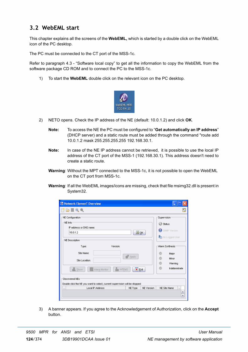
User Manual
NE management by software application
9500 MPR for ANSI and ETSI
3DB19901DCAA Issue 01124/374
3.2 WebEML start
This chapter explains all the screens of the WebEML, which is started by a double click on the WebEMLicon of the PC desktop.
The PC must be connected to the CT port of the MSS-1c.
Refer to paragraph 4.3 - �Software local copy� to get all the information to copy the WebEML from thesoftware package CD ROM and to connect the PC to the MSS-1c.
1) To start the WebEML double click on the relevant icon on the PC desktop.
2) NETO opens. Check the IP address of the NE (default: 10.0.1.2) and click OK.
Note: To access the NE the PC must be configured to �Get automatically an IP address�(DHCP server) and a static route must be added through the command "route add10.0.1.2 mask 255.255.255.255 192.168.30.1.
Note: In case of the NE IP address cannot be retrieved, it is possible to use the local IPaddress of the CT port of the MSS-1 (192.168.30.1). This address doesn't need tocreate a static route.
Warning: Without the MPT connected to the MSS-1c, it is not possible to open the WebEML on the CT port from MSS-1c.
Warning: If all the WebEML images/icons are missing, check that file msimg32.dll is present inSystem32.
3) A banner appears. If you agree to the Acknowledgement of Authorization, click on the Acceptbutton.
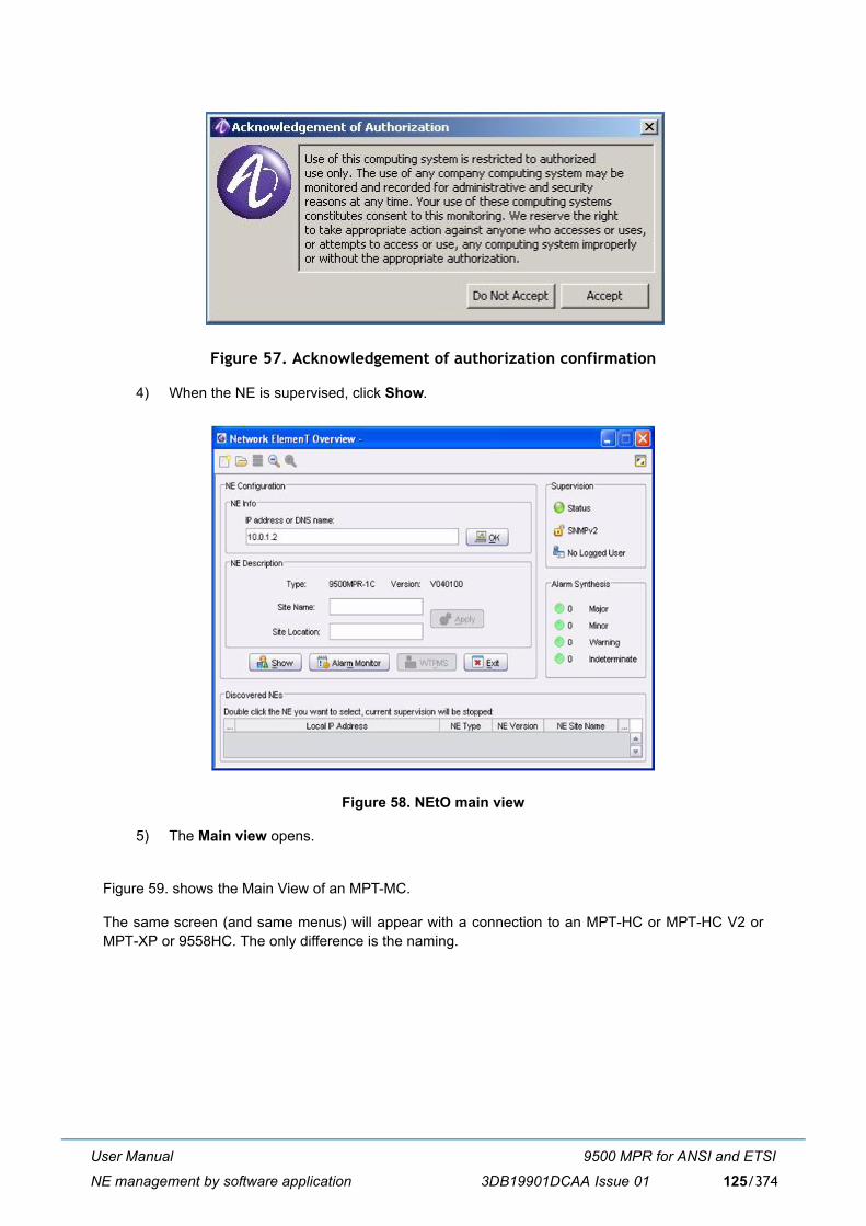
User Manual
NE management by software application
9500 MPR for ANSI and ETSI
3DB19901DCAA Issue 01 125/374
Figure 57. Acknowledgement of authorization confirmation
4) When the NE is supervised, click Show.
Figure 58. NEtO main view
5) The Main view opens.
Figure 59. shows the Main View of an MPT-MC.
The same screen (and same menus) will appear with a connection to an MPT-HC or MPT-HC V2 orMPT-XP or 9558HC. The only difference is the naming.
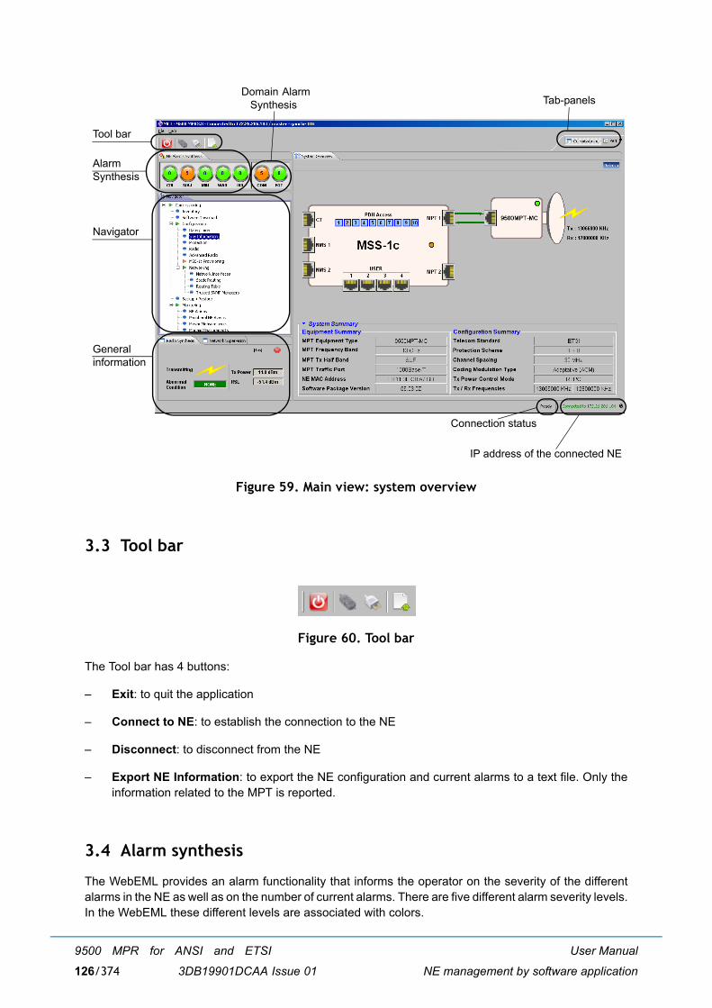
User Manual
NE management by software application
9500 MPR for ANSI and ETSI
3DB19901DCAA Issue 01126/374
Figure 59. Main view: system overview
3.3 Tool bar
Figure 60. Tool bar
The Tool bar has 4 buttons:
� Exit: to quit the application
� Connect to NE: to establish the connection to the NE
� Disconnect: to disconnect from the NE
� Export NE Information: to export the NE configuration and current alarms to a text file. Only theinformation related to the MPT is reported.
3.4 Alarm synthesis
The WebEML provides an alarm functionality that informs the operator on the severity of the differentalarms in the NE as well as on the number of current alarms. There are five different alarm severity levels.In the WebEML these different levels are associated with colors.
Tool bar
AlarmSynthesis
Navigator
Generalinformation
Domain Alarm Synthesis Tab-panels
IP address of the connected NE
Connection status
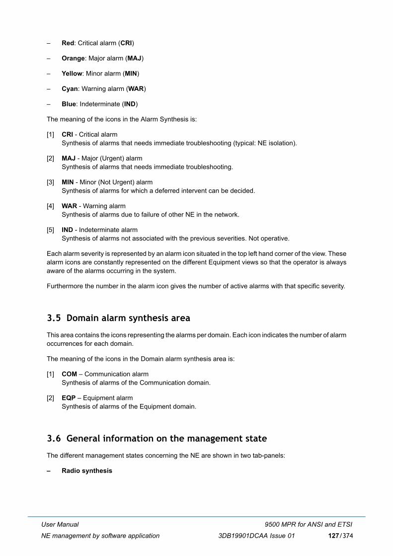
User Manual
NE management by software application
9500 MPR for ANSI and ETSI
3DB19901DCAA Issue 01 127/374
� Red: Critical alarm (CRI)
� Orange: Major alarm (MAJ)
� Yellow: Minor alarm (MIN)
� Cyan: Warning alarm (WAR)
� Blue: Indeterminate (IND)
The meaning of the icons in the Alarm Synthesis is:
[1] CRI - Critical alarmSynthesis of alarms that needs immediate troubleshooting (typical: NE isolation).
[2] MAJ - Major (Urgent) alarmSynthesis of alarms that needs immediate troubleshooting.
[3] MIN - Minor (Not Urgent) alarmSynthesis of alarms for which a deferred intervent can be decided.
[4] WAR - Warning alarmSynthesis of alarms due to failure of other NE in the network.
[5] IND - Indeterminate alarmSynthesis of alarms not associated with the previous severities. Not operative.
Each alarm severity is represented by an alarm icon situated in the top left hand corner of the view. Thesealarm icons are constantly represented on the different Equipment views so that the operator is alwaysaware of the alarms occurring in the system.
Furthermore the number in the alarm icon gives the number of active alarms with that specific severity.
3.5 Domain alarm synthesis area
This area contains the icons representing the alarms per domain. Each icon indicates the number of alarmoccurrences for each domain.
The meaning of the icons in the Domain alarm synthesis area is:
[1] COM � Communication alarmSynthesis of alarms of the Communication domain.
[2] EQP � Equipment alarmSynthesis of alarms of the Equipment domain.
3.6 General information on the management state
The different management states concerning the NE are shown in two tab-panels:
� Radio synthesis
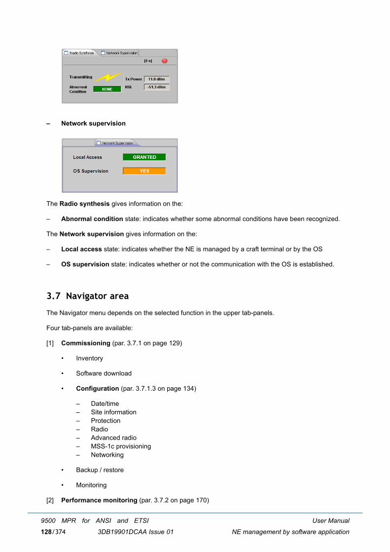
User Manual
NE management by software application
9500 MPR for ANSI and ETSI
3DB19901DCAA Issue 01128/374
� Network supervision
The Radio synthesis gives information on the:
� Abnormal condition state: indicates whether some abnormal conditions have been recognized.
The Network supervision gives information on the:
� Local access state: indicates whether the NE is managed by a craft terminal or by the OS
� OS supervision state: indicates whether or not the communication with the OS is established.
3.7 Navigator area
The Navigator menu depends on the selected function in the upper tab-panels.
Four tab-panels are available:
[1] Commissioning (par. 3.7.1 on page 129)
� Inventory
� Software download
� Configuration (par. 3.7.1.3 on page 134)
� Date/time� Site information� Protection� Radio� Advanced radio� MSS-1c provisioning� Networking
� Backup / restore
� Monitoring
[2] Performance monitoring (par. 3.7.2 on page 170)
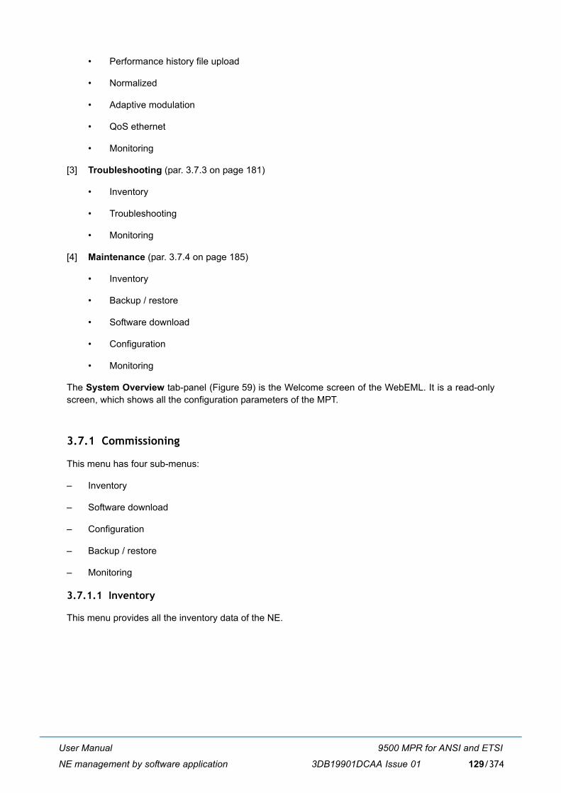
User Manual
NE management by software application
9500 MPR for ANSI and ETSI
3DB19901DCAA Issue 01 129/374
� Performance history file upload
� Normalized
� Adaptive modulation
� QoS ethernet
� Monitoring
[3] Troubleshooting (par. 3.7.3 on page 181)
� Inventory
� Troubleshooting
� Monitoring
[4] Maintenance (par. 3.7.4 on page 185)
� Inventory
� Backup / restore
� Software download
� Configuration
� Monitoring
The System Overview tab-panel (Figure 59) is the Welcome screen of the WebEML. It is a read-onlyscreen, which shows all the configuration parameters of the MPT.
3.7.1 Commissioning
This menu has four sub-menus:
� Inventory
� Software download
� Configuration
� Backup / restore
� Monitoring
3.7.1.1 Inventory
This menu provides all the inventory data of the NE.
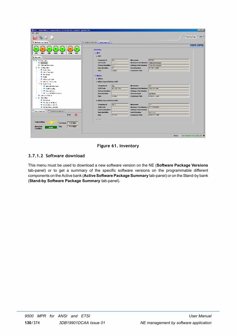
User Manual
NE management by software application
9500 MPR for ANSI and ETSI
3DB19901DCAA Issue 01130/374
Figure 61. Inventory
3.7.1.2 Software download
This menu must be used to download a new software version on the NE (Software Package Versionstab-panel) or to get a summary of the specific software versions on the programmable differentcomponents on the Active bank (Active Software Package Summary tab-panel) or on the Stand-by bank(Stand-by Software Package Summary tab-panel).
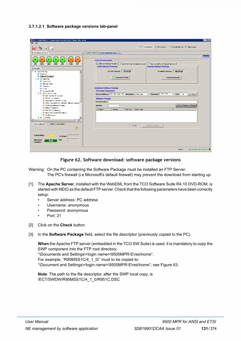
User Manual
NE management by software application
9500 MPR for ANSI and ETSI
3DB19901DCAA Issue 01 131/374
3.7.1.2.1 Software package versions tab-panel
Figure 62. Software download: software package versions
Warning: On the PC containing the Software Package must be installed an FTP Server.The PC's firewall (i.e Microsoft's default firewall) may prevent the download from starting up.
[1] The Apache Server, installed with the WebEML from the TCO Software Suite R4.10 DVD-ROM, isstarted with NEtO as the default FTP server. Check that the following parameters have been correctlysetup:� Server address: PC address� Username: anonymous� Password: anonymous� Port: 21
[2] Click on the Check button.
[3] In the Software Package field, select the file descriptor (previously copied to the PC).
When the Apache FTP server (embedded in the TCO SW Suite) is used, it is mandatory to copy theSWP component into the FTP root directory:�\Documents and Settings\<login name>\9500MPR-E\res\home�. For example, �R95MSS1C/4_1_0/� must to be copied to:�\Document and Settings\<login name>\9500MPR-E\res\home�; see Figure 63.
Note: The path to the file descriptor, after the SWP local copy, is /ECT/SWDW/R95MSS1C/4_1_0/R951C.DSC
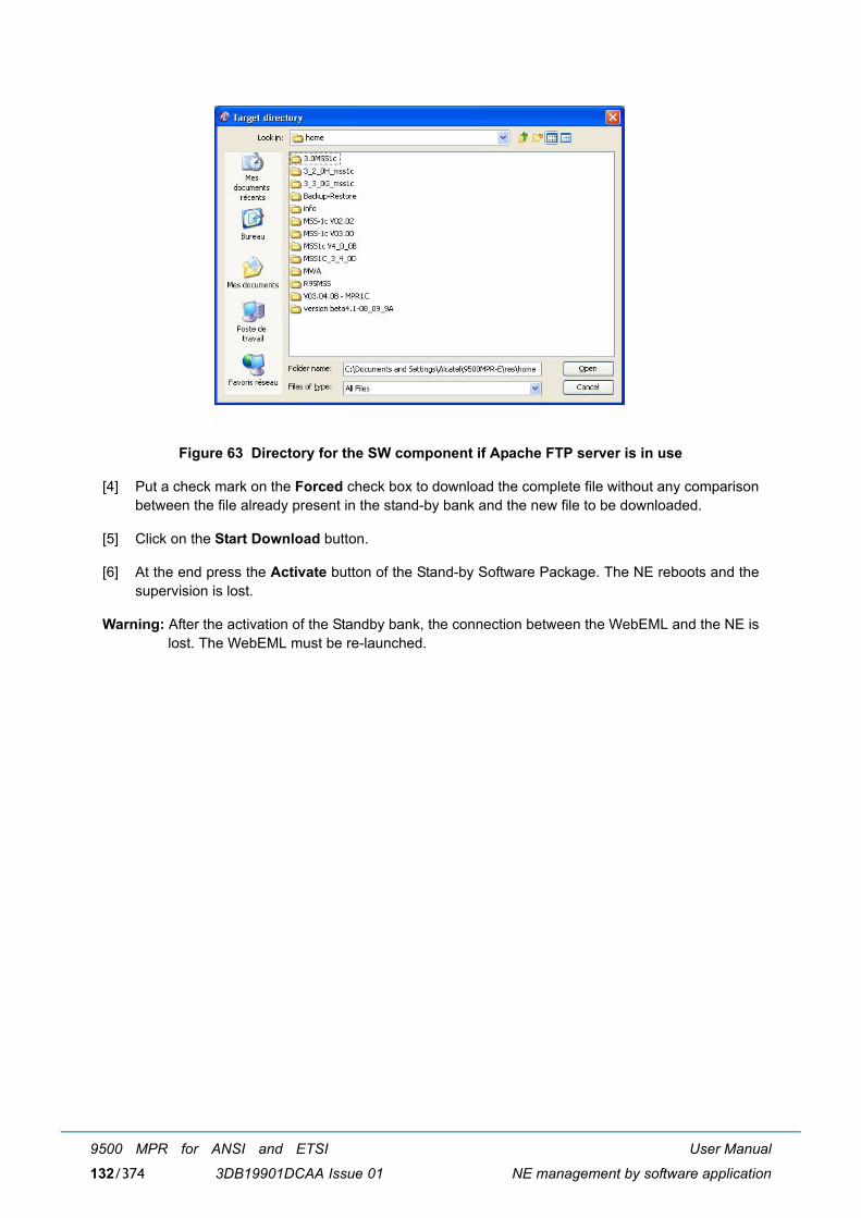
User Manual
NE management by software application
9500 MPR for ANSI and ETSI
3DB19901DCAA Issue 01132/374
Figure 63 Directory for the SW component if Apache FTP server is in use
[4] Put a check mark on the Forced check box to download the complete file without any comparisonbetween the file already present in the stand-by bank and the new file to be downloaded.
[5] Click on the Start Download button.
[6] At the end press the Activate button of the Stand-by Software Package. The NE reboots and thesupervision is lost.
Warning: After the activation of the Standby bank, the connection between the WebEML and the NE islost. The WebEML must be re-launched.
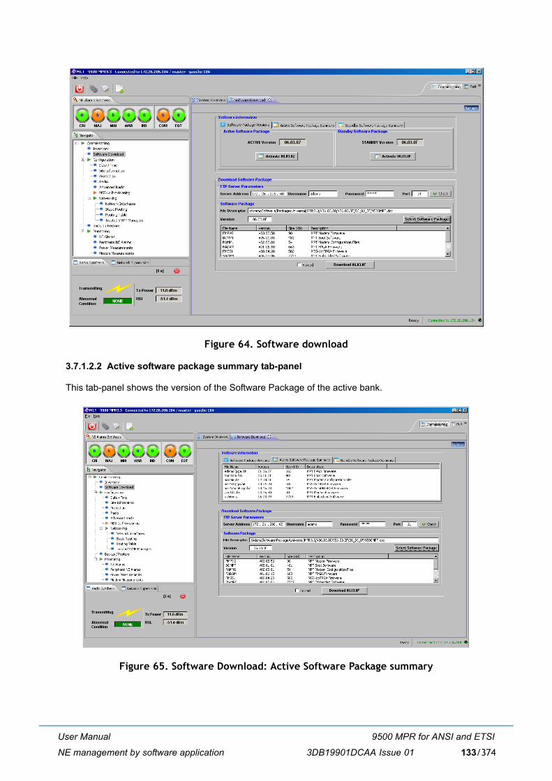
User Manual
NE management by software application
9500 MPR for ANSI and ETSI
3DB19901DCAA Issue 01 133/374
Figure 64. Software download
3.7.1.2.2 Active software package summary tab-panel
This tab-panel shows the version of the Software Package of the active bank.
Figure 65. Software Download: Active Software Package summary
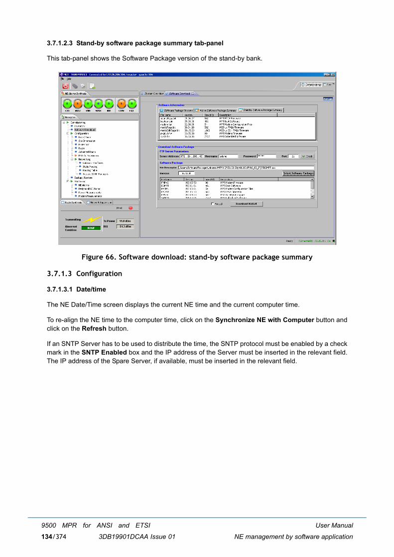
User Manual
NE management by software application
9500 MPR for ANSI and ETSI
3DB19901DCAA Issue 01134/374
3.7.1.2.3 Stand-by software package summary tab-panel
This tab-panel shows the Software Package version of the stand-by bank.
Figure 66. Software download: stand-by software package summary
3.7.1.3 Configuration
3.7.1.3.1 Date/time
The NE Date/Time screen displays the current NE time and the current computer time.
To re-align the NE time to the computer time, click on the Synchronize NE with Computer button andclick on the Refresh button.
If an SNTP Server has to be used to distribute the time, the SNTP protocol must be enabled by a checkmark in the SNTP Enabled box and the IP address of the Server must be inserted in the relevant field.The IP address of the Spare Server, if available, must be inserted in the relevant field.
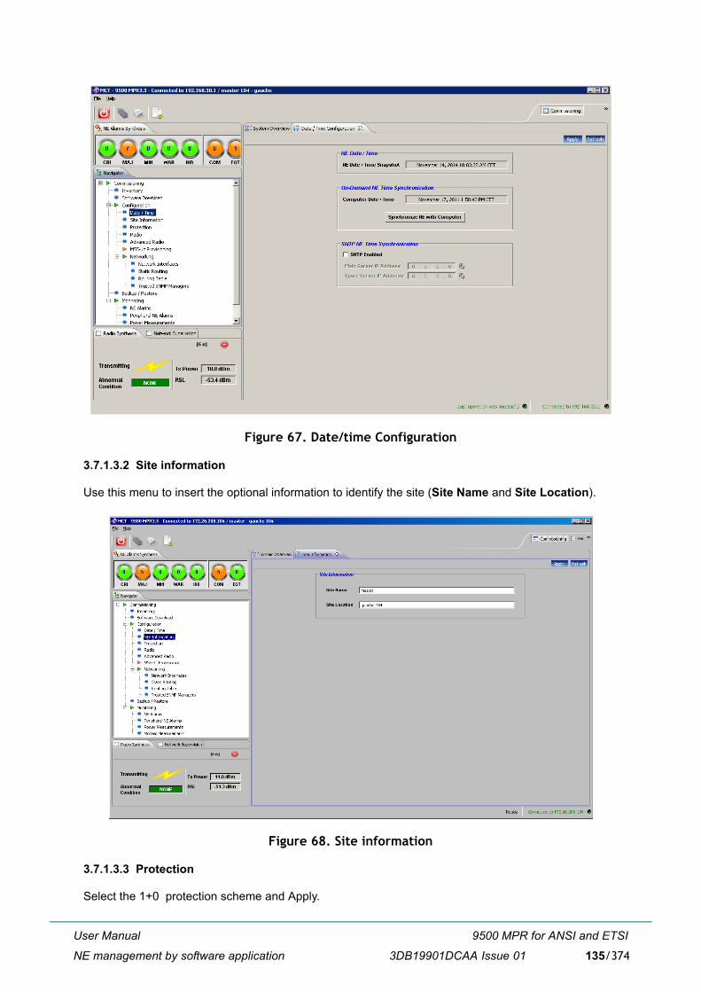
User Manual
NE management by software application
9500 MPR for ANSI and ETSI
3DB19901DCAA Issue 01 135/374
Figure 67. Date/time Configuration
3.7.1.3.2 Site information
Use this menu to insert the optional information to identify the site (Site Name and Site Location).
Figure 68. Site information
3.7.1.3.3 Protection
Select the 1+0 protection scheme and Apply.
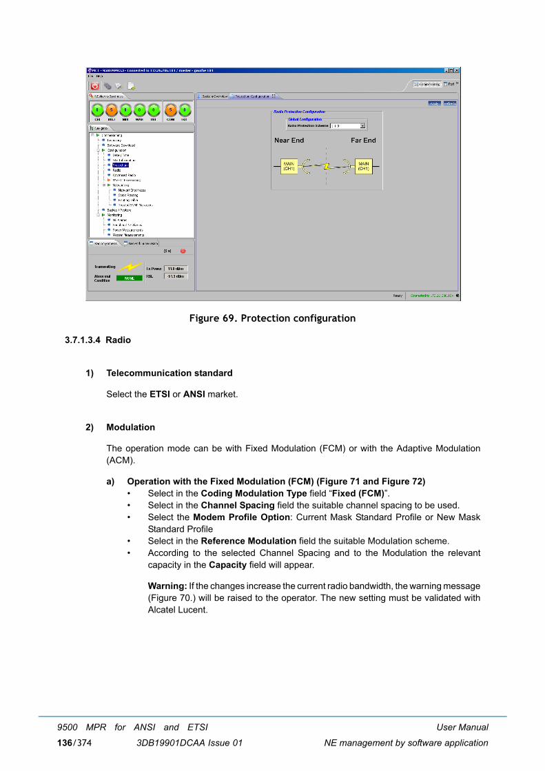
User Manual
NE management by software application
9500 MPR for ANSI and ETSI
3DB19901DCAA Issue 01136/374
Figure 69. Protection configuration
3.7.1.3.4 Radio
1) Telecommunication standard
Select the ETSI or ANSI market.
2) Modulation
The operation mode can be with Fixed Modulation (FCM) or with the Adaptive Modulation(ACM).
a) Operation with the Fixed Modulation (FCM) (Figure 71 and Figure 72)� Select in the Coding Modulation Type field �Fixed (FCM)�.� Select in the Channel Spacing field the suitable channel spacing to be used.� Select the Modem Profile Option: Current Mask Standard Profile or New Mask
Standard Profile� Select in the Reference Modulation field the suitable Modulation scheme.� According to the selected Channel Spacing and to the Modulation the relevant
capacity in the Capacity field will appear.
Warning: If the changes increase the current radio bandwidth, the warning message(Figure 70.) will be raised to the operator. The new setting must be validated withAlcatel Lucent.
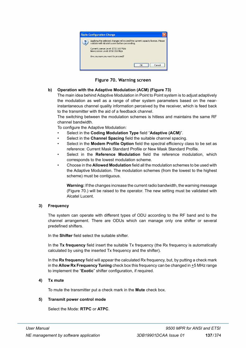
User Manual
NE management by software application
9500 MPR for ANSI and ETSI
3DB19901DCAA Issue 01 137/374
Figure 70. Warning screen
b) Operation with the Adaptive Modulation (ACM) (Figure 73)The main idea behind Adaptive Modulation in Point to Point system is to adjust adaptivelythe modulation as well as a range of other system parameters based on the near-instantaneous channel quality information perceived by the receiver, which is feed backto the transmitter with the aid of a feedback channel.The switching between the modulation schemes is hitless and maintains the same RFchannel bandwidth.To configure the Adaptive Modulation:� Select in the Coding Modulation Type field �Adaptive (ACM)�.� Select in the Channel Spacing field the suitable channel spacing. � Select in the Modem Profile Option field the spectral efficiency class to be set as
reference: Current Mask Standard Profile or New Mask Standard Profile. � Select in the Reference Modulation field the reference modulation, which
corresponds to the lowest modulation scheme.� Choose in the Allowed Modulation field all the modulation schemes to be used with
the Adaptive Modulation. The modulation schemes (from the lowest to the highestscheme) must be contiguous.
Warning: If the changes increase the current radio bandwidth, the warning message(Figure 70.) will be raised to the operator. The new setting must be validated withAlcatel Lucent.
3) Frequency
The system can operate with different types of ODU according to the RF band and to thechannel arrangement. There are ODUs which can manage only one shifter or severalpredefined shifters.
In the Shifter field select the suitable shifter.
In the Tx frequency field insert the suitable Tx frequency (the Rx frequency is automaticallycalculated by using the inserted Tx frequency and the shifter).
In the Rx frequency field will appear the calculated Rx frequency, but, by putting a check markin the Allow Rx Frequency Tuning check box this frequency can be changed in +5 MHz rangeto implement the �Exotic� shifter configuration, if required.
4) Tx mute
To mute the transmitter put a check mark in the Mute check box.
5) Transmit power control mode
Select the Mode: RTPC or ATPC.

User Manual
NE management by software application
9500 MPR for ANSI and ETSI
3DB19901DCAA Issue 01138/374
6) RTPC settings
� Tx power without adaptive modulation
If the ATPC is disabled the Tx Power field is available. For the Tx Power range refer tothe indication in the screen.
In this field write the new value within the allowed transmitted power range.
� Tx Power with adaptive modulation
The operator can modify only the Tx power relevant to the lowest modulation scheme. Inthis field the operator has to enter the constant power, which will be used with the lowestmodulation.
Note: The same power value will be used by the other modulation schemes.
7) ATPC settings
The ATPC cannot be set with ACM (only with FCM).
� ATPC remote RSL threshold
The value of the low power threshold can be changed by writing the new value in the field.When the Rx power is equal to this power the ATPC algorithm starts to operate.
� Min ATPC Tx power and Max ATPC Tx power
The Min Tx power and Max Tx power, regarding the Tx Range in the ATPC management,can be written in the relevant field.
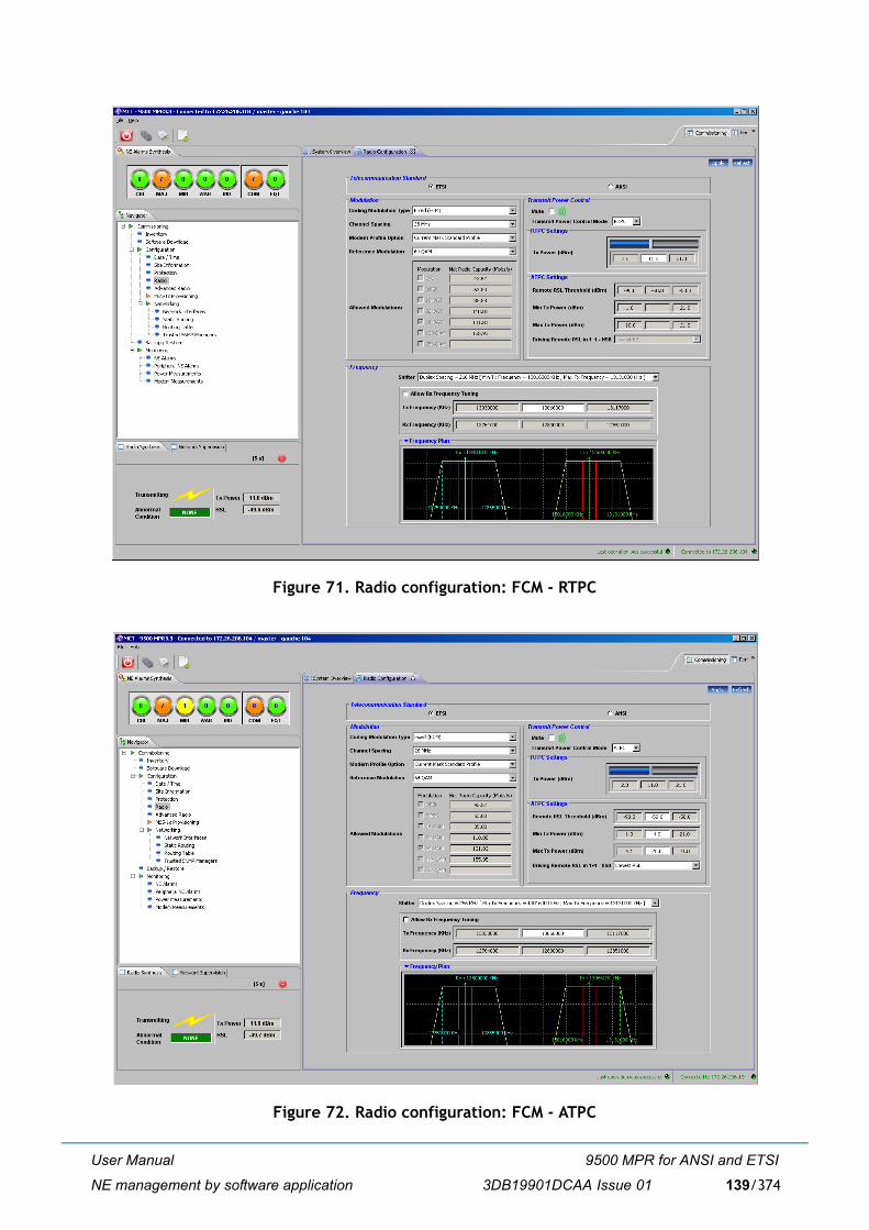
User Manual
NE management by software application
9500 MPR for ANSI and ETSI
3DB19901DCAA Issue 01 139/374
Figure 71. Radio configuration: FCM - RTPC
Figure 72. Radio configuration: FCM - ATPC
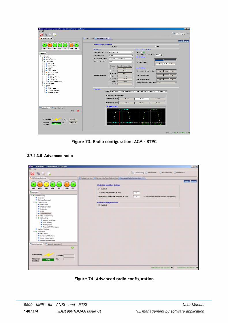
User Manual
NE management by software application
9500 MPR for ANSI and ETSI
3DB19901DCAA Issue 01140/374
Figure 73. Radio configuration: ACM - RTPC
3.7.1.3.5 Advanced radio
Figure 74. Advanced radio configuration
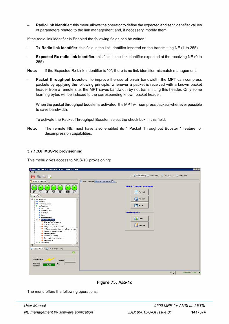
User Manual
NE management by software application
9500 MPR for ANSI and ETSI
3DB19901DCAA Issue 01 141/374
� Radio link identifier: this menu allows the operator to define the expected and sent identifier valuesof parameters related to the link management and, if necessary, modify them.
If the radio link identifier is Enabled the following fields can be written:
� Tx Radio link identifier: this field is the link identifier inserted on the transmitting NE (1 to 255)
� Expected Rx radio link identifier: this field is the link identifier expected at the receiving NE (0 to255)
Note: If the Expected Rx Link Indentifier is "0", there is no link identifier mismatch management.
� Packet throughput booster: to improve the use of on-air bandwidth, the MPT can compresspackets by applying the following principle: whenever a packet is received with a known packetheader from a remote site, the MPT saves bandwidth by not transmitting this header. Only somelearning bytes will be indexed to the corresponding known packet header.
When the packet throughput booster is activated, the MPT will compress packets whenever possibleto save bandwidth.
To activate the Packet Throughput Booster, select the check box in this field.
Note: The remote NE must have also enabled its " Packet Throughput Booster " feature fordecompression capabilities.
3.7.1.3.6 MSS-1c provisioning
This menu gives access to MSS-1C provisioning:
Figure 75. MSS-1c
The menu offers the following operations:
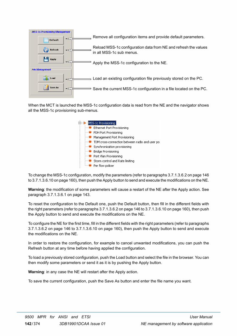
User Manual
NE management by software application
9500 MPR for ANSI and ETSI
3DB19901DCAA Issue 01142/374
When the MCT is launched the MSS-1c configuration data is read from the NE and the navigator showsall the MSS-1c provisioning sub-menus.
To change the MSS-1c configuration, modify the parameters (refer to paragraphs 3.7.1.3.6.2 on page 146to 3.7.1.3.6.10 on page 160), then push the Apply button to send and execute the modifications on the NE.
Warning: the modification of some parameters will cause a restart of the NE after the Apply action. Seeparagraph 3.7.1.3.6.1 on page 143.
To reset the configuration to the Default one, push the Default button, then fill in the different fields withthe right parameters (refer to paragraphs 3.7.1.3.6.2 on page 146 to 3.7.1.3.6.10 on page 160), then pushthe Apply button to send and execute the modifications on the NE.
To configure the NE for the first time, fill in the different fields with the right parameters (refer to paragraphs3.7.1.3.6.2 on page 146 to 3.7.1.3.6.10 on page 160), then push the Apply button to send and executethe modifications on the NE.
In order to restore the configuration, for example to cancel unwanted modifications, you can push theRefresh button at any time before having applied the configuration.
To load a previously stored configuration, push the Load button and select the file in the browser. You canthen modify some parameters or send it as it is by pushing the Apply button.
Warning: in any case the NE will restart after the Apply action.
To save the current configuration, push the Save As button and enter the file name you want.
Remove all configuration items and provide default parameters.
Reload MSS-1c configuration data from NE and refresh the valuesin all MSS-1c sub menus.
Apply the MSS-1c configuration to the NE.
Load an existing configuration file previously stored on the PC.
Save the current MSS-1c configuration in a file located on the PC.
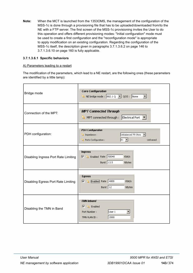
User Manual
NE management by software application
9500 MPR for ANSI and ETSI
3DB19901DCAA Issue 01 143/374
Note: When the MCT is launched from the 1353OMS, the management of the configuration of the MSS-1c is done through a provisioning file that has to be uploaded/downloaded from/to the NE with a FTP server. The first screen of the MSS-1c provisioning invites the User to do this operation and offers different provisioning modes: "Initial configuration" mode must be used to create a first configuration and the "reconfiguration mode" is appropriate to apply modification on an existing configuration. Regarding the configuration of the MSS-1c itself, the description given in paragraphs 3.7.1.3.6.2 on page 146 to 3.7.1.3.6.10 on page 160 is fully applicable.
3.7.1.3.6.1 Specific behaviors
A) Parameters leading to a restart
The modification of the parameters, which lead to a NE restart, are the following ones (these parametersare identified by a little lamp):
Bridge mode
Connection of the MPT:
PDH configuration:
Disabling Ingress Port Rate Limiting
Disabling Egress Port Rate Limiting
Disabling the TMN in Band
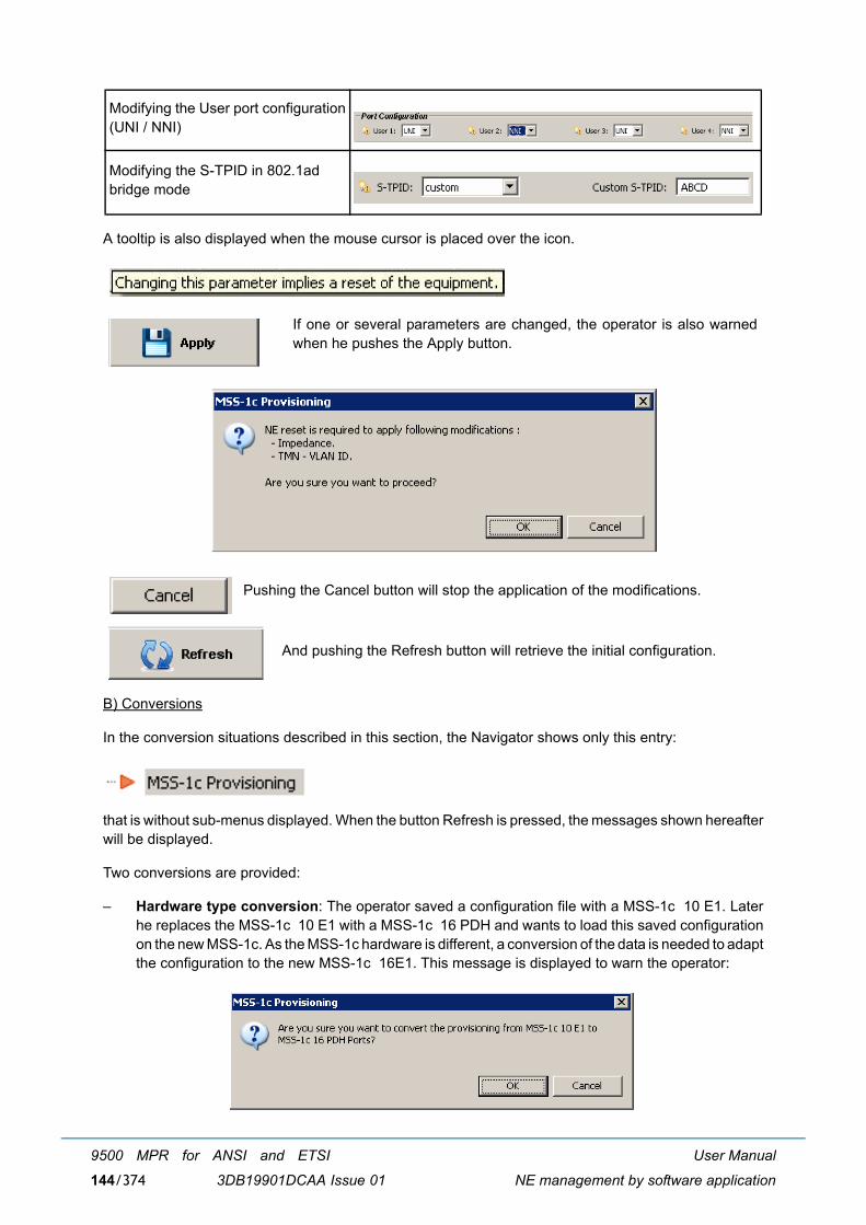
User Manual
NE management by software application
9500 MPR for ANSI and ETSI
3DB19901DCAA Issue 01144/374
A tooltip is also displayed when the mouse cursor is placed over the icon.
B) Conversions
In the conversion situations described in this section, the Navigator shows only this entry:
that is without sub-menus displayed. When the button Refresh is pressed, the messages shown hereafterwill be displayed.
Two conversions are provided:
� Hardware type conversion: The operator saved a configuration file with a MSS-1c 10 E1. Laterhe replaces the MSS-1c 10 E1 with a MSS-1c 16 PDH and wants to load this saved configurationon the new MSS-1c. As the MSS-1c hardware is different, a conversion of the data is needed to adaptthe configuration to the new MSS-1c 16E1. This message is displayed to warn the operator:
Modifying the User port configuration(UNI / NNI)
Modifying the S-TPID in 802.1adbridge mode
If one or several parameters are changed, the operator is also warnedwhen he pushes the Apply button.
Pushing the Cancel button will stop the application of the modifications.
And pushing the Refresh button will retrieve the initial configuration.
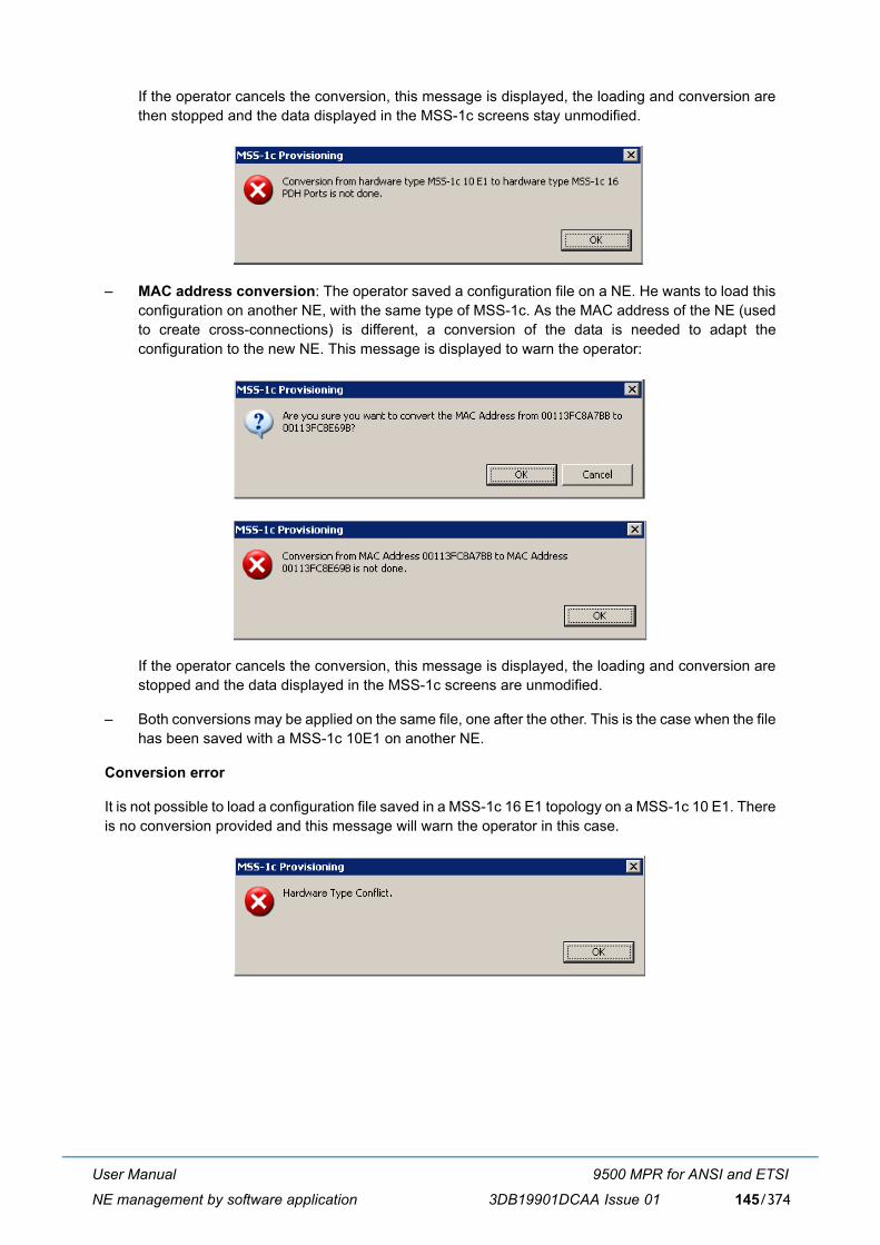
User Manual
NE management by software application
9500 MPR for ANSI and ETSI
3DB19901DCAA Issue 01 145/374
If the operator cancels the conversion, this message is displayed, the loading and conversion arethen stopped and the data displayed in the MSS-1c screens stay unmodified.
� MAC address conversion: The operator saved a configuration file on a NE. He wants to load thisconfiguration on another NE, with the same type of MSS-1c. As the MAC address of the NE (usedto create cross-connections) is different, a conversion of the data is needed to adapt theconfiguration to the new NE. This message is displayed to warn the operator:
If the operator cancels the conversion, this message is displayed, the loading and conversion arestopped and the data displayed in the MSS-1c screens are unmodified.
� Both conversions may be applied on the same file, one after the other. This is the case when the filehas been saved with a MSS-1c 10E1 on another NE.
Conversion error
It is not possible to load a configuration file saved in a MSS-1c 16 E1 topology on a MSS-1c 10 E1. Thereis no conversion provided and this message will warn the operator in this case.
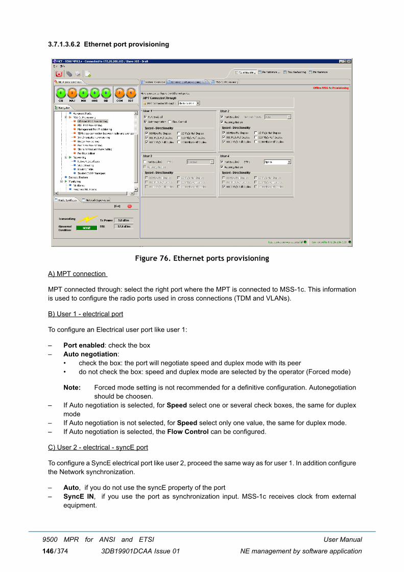
User Manual
NE management by software application
9500 MPR for ANSI and ETSI
3DB19901DCAA Issue 01146/374
3.7.1.3.6.2 Ethernet port provisioning
Figure 76. Ethernet ports provisioning
A) MPT connection
MPT connected through: select the right port where the MPT is connected to MSS-1c. This informationis used to configure the radio ports used in cross connections (TDM and VLANs).
B) User 1 - electrical port
To configure an Electrical user port like user 1:
� Port enabled: check the box� Auto negotiation:
� check the box: the port will negotiate speed and duplex mode with its peer� do not check the box: speed and duplex mode are selected by the operator (Forced mode)
Note: Forced mode setting is not recommended for a definitive configuration. Autonegotiationshould be choosen.
� If Auto negotiation is selected, for Speed select one or several check boxes, the same for duplexmode
� If Auto negotiation is not selected, for Speed select only one value, the same for duplex mode.� If Auto negotiation is selected, the Flow Control can be configured.
C) User 2 - electrical - syncE port
To configure a SyncE electrical port like user 2, proceed the same way as for user 1. In addition configurethe Network synchronization.
� Auto, if you do not use the syncE property of the port� SyncE IN, if you use the port as synchronization input. MSS-1c receives clock from external
equipment.
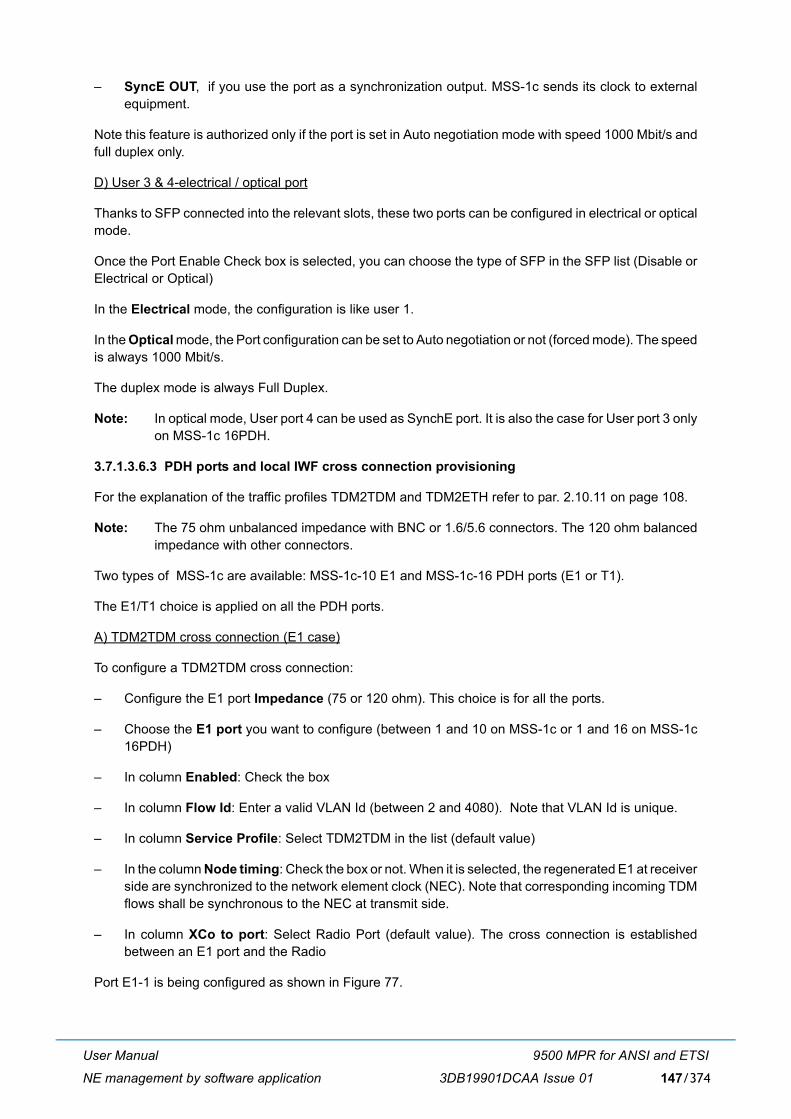
User Manual
NE management by software application
9500 MPR for ANSI and ETSI
3DB19901DCAA Issue 01 147/374
� SyncE OUT, if you use the port as a synchronization output. MSS-1c sends its clock to externalequipment.
Note this feature is authorized only if the port is set in Auto negotiation mode with speed 1000 Mbit/s andfull duplex only.
D) User 3 & 4-electrical / optical port
Thanks to SFP connected into the relevant slots, these two ports can be configured in electrical or opticalmode.
Once the Port Enable Check box is selected, you can choose the type of SFP in the SFP list (Disable orElectrical or Optical)
In the Electrical mode, the configuration is like user 1.
In the Optical mode, the Port configuration can be set to Auto negotiation or not (forced mode). The speedis always 1000 Mbit/s.
The duplex mode is always Full Duplex.
Note: In optical mode, User port 4 can be used as SynchE port. It is also the case for User port 3 onlyon MSS-1c 16PDH.
3.7.1.3.6.3 PDH ports and local IWF cross connection provisioning
For the explanation of the traffic profiles TDM2TDM and TDM2ETH refer to par. 2.10.11 on page 108.
Note: The 75 ohm unbalanced impedance with BNC or 1.6/5.6 connectors. The 120 ohm balancedimpedance with other connectors.
Two types of MSS-1c are available: MSS-1c-10 E1 and MSS-1c-16 PDH ports (E1 or T1).
The E1/T1 choice is applied on all the PDH ports.
A) TDM2TDM cross connection (E1 case)
To configure a TDM2TDM cross connection:
� Configure the E1 port Impedance (75 or 120 ohm). This choice is for all the ports.
� Choose the E1 port you want to configure (between 1 and 10 on MSS-1c or 1 and 16 on MSS-1c16PDH)
� In column Enabled: Check the box
� In column Flow Id: Enter a valid VLAN Id (between 2 and 4080). Note that VLAN Id is unique.
� In column Service Profile: Select TDM2TDM in the list (default value)
� In the column Node timing: Check the box or not. When it is selected, the regenerated E1 at receiverside are synchronized to the network element clock (NEC). Note that corresponding incoming TDMflows shall be synchronous to the NEC at transmit side.
� In column XCo to port: Select Radio Port (default value). The cross connection is establishedbetween an E1 port and the Radio
Port E1-1 is being configured as shown in Figure 77.
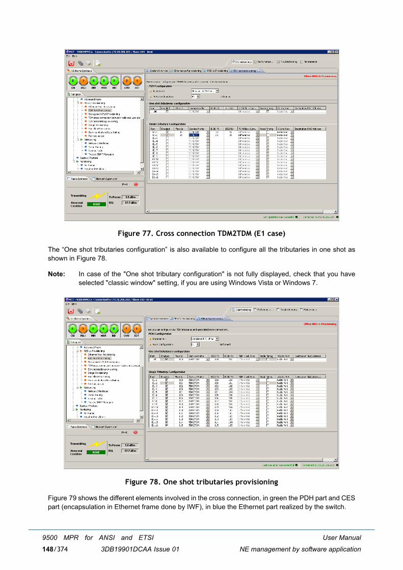
User Manual
NE management by software application
9500 MPR for ANSI and ETSI
3DB19901DCAA Issue 01148/374
Figure 77. Cross connection TDM2TDM (E1 case)
The �One shot tributaries configuration� is also available to configure all the tributaries in one shot asshown in Figure 78.
Note: In case of the "One shot tributary configuration" is not fully displayed, check that you haveselected "classic window" setting, if you are using Windows Vista or Windows 7.
Figure 78. One shot tributaries provisioning
Figure 79 shows the different elements involved in the cross connection, in green the PDH part and CESpart (encapsulation in Ethernet frame done by IWF), in blue the Ethernet part realized by the switch.
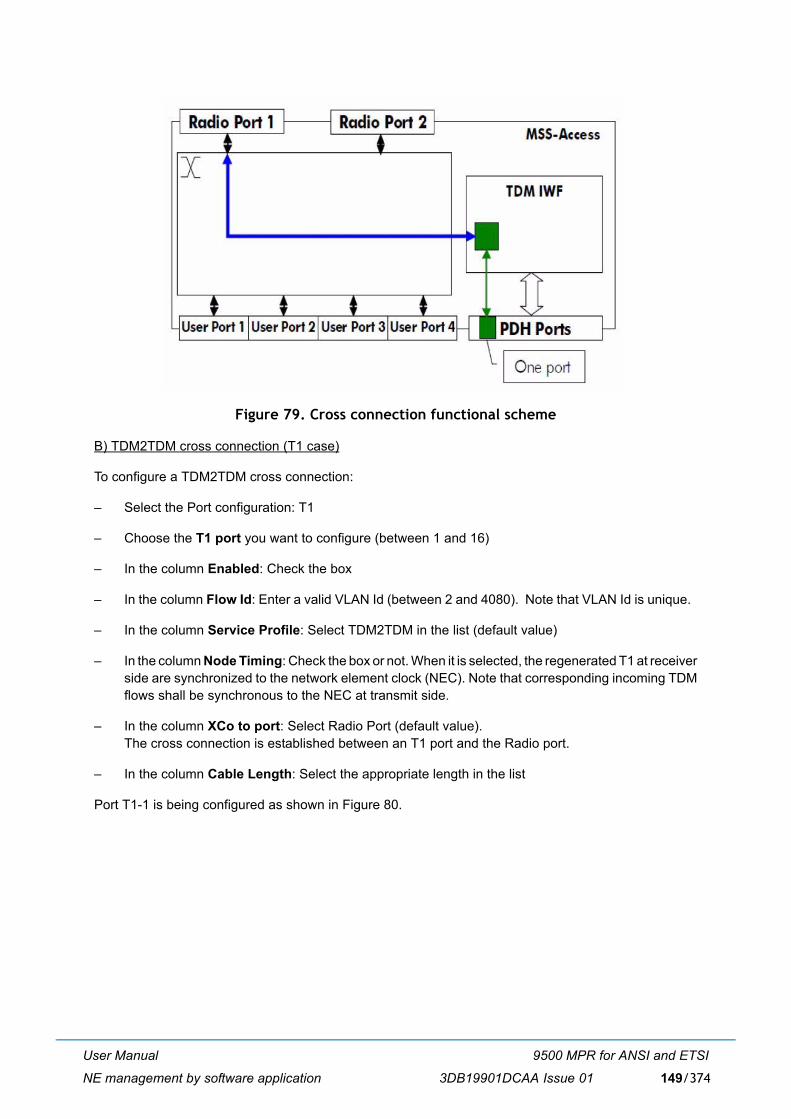
User Manual
NE management by software application
9500 MPR for ANSI and ETSI
3DB19901DCAA Issue 01 149/374
Figure 79. Cross connection functional scheme
B) TDM2TDM cross connection (T1 case)
To configure a TDM2TDM cross connection:
� Select the Port configuration: T1
� Choose the T1 port you want to configure (between 1 and 16)
� In the column Enabled: Check the box
� In the column Flow Id: Enter a valid VLAN Id (between 2 and 4080). Note that VLAN Id is unique.
� In the column Service Profile: Select TDM2TDM in the list (default value)
� In the column Node Timing: Check the box or not. When it is selected, the regenerated T1 at receiverside are synchronized to the network element clock (NEC). Note that corresponding incoming TDMflows shall be synchronous to the NEC at transmit side.
� In the column XCo to port: Select Radio Port (default value). The cross connection is established between an T1 port and the Radio port.
� In the column Cable Length: Select the appropriate length in the list
Port T1-1 is being configured as shown in Figure 80.
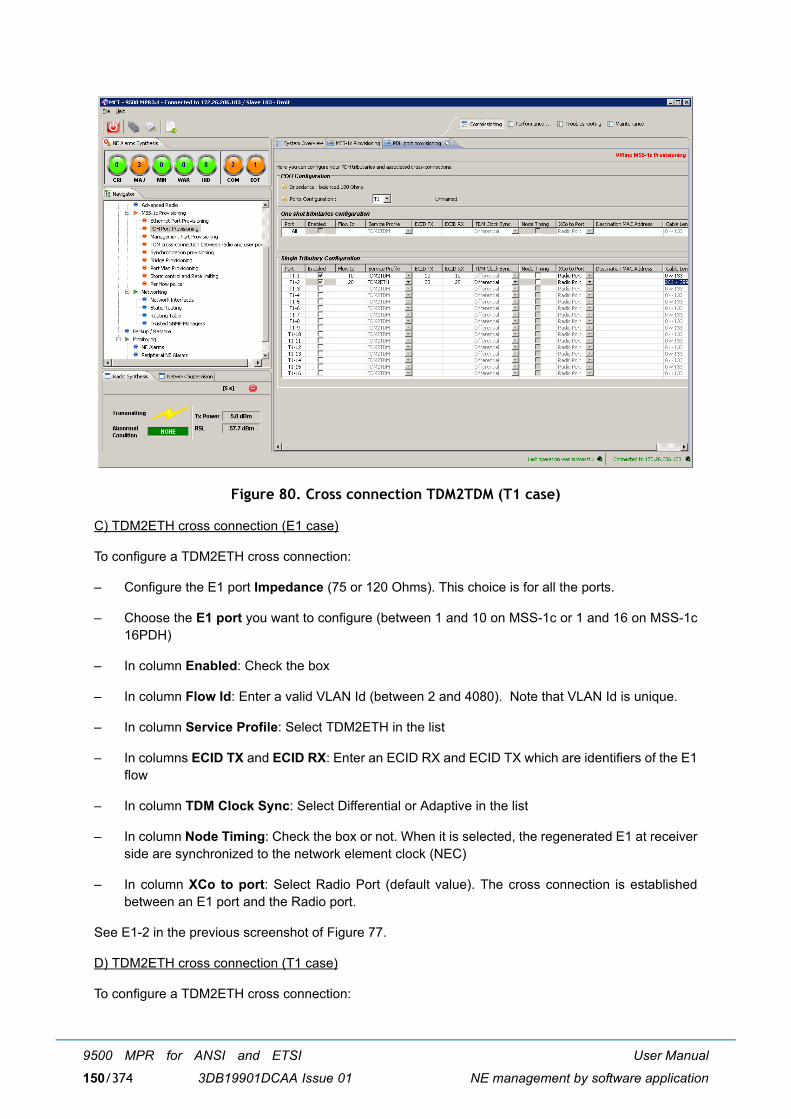
User Manual
NE management by software application
9500 MPR for ANSI and ETSI
3DB19901DCAA Issue 01150/374
Figure 80. Cross connection TDM2TDM (T1 case)
C) TDM2ETH cross connection (E1 case)
To configure a TDM2ETH cross connection:
� Configure the E1 port Impedance (75 or 120 Ohms). This choice is for all the ports.
� Choose the E1 port you want to configure (between 1 and 10 on MSS-1c or 1 and 16 on MSS-1c16PDH)
� In column Enabled: Check the box
� In column Flow Id: Enter a valid VLAN Id (between 2 and 4080). Note that VLAN Id is unique.
� In column Service Profile: Select TDM2ETH in the list
� In columns ECID TX and ECID RX: Enter an ECID RX and ECID TX which are identifiers of the E1flow
� In column TDM Clock Sync: Select Differential or Adaptive in the list
� In column Node Timing: Check the box or not. When it is selected, the regenerated E1 at receiverside are synchronized to the network element clock (NEC)
� In column XCo to port: Select Radio Port (default value). The cross connection is establishedbetween an E1 port and the Radio port.
See E1-2 in the previous screenshot of Figure 77.
D) TDM2ETH cross connection (T1 case)
To configure a TDM2ETH cross connection:
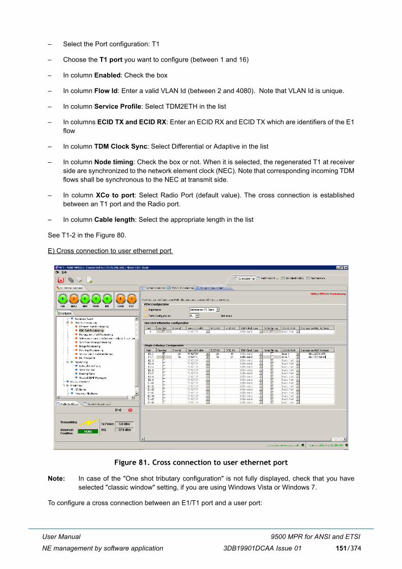
User Manual
NE management by software application
9500 MPR for ANSI and ETSI
3DB19901DCAA Issue 01 151/374
� Select the Port configuration: T1
� Choose the T1 port you want to configure (between 1 and 16)
� In column Enabled: Check the box
� In column Flow Id: Enter a valid VLAN Id (between 2 and 4080). Note that VLAN Id is unique.
� In column Service Profile: Select TDM2ETH in the list
� In columns ECID TX and ECID RX: Enter an ECID RX and ECID TX which are identifiers of the E1flow
� In column TDM Clock Sync: Select Differential or Adaptive in the list
� In column Node timing: Check the box or not. When it is selected, the regenerated T1 at receiverside are synchronized to the network element clock (NEC). Note that corresponding incoming TDMflows shall be synchronous to the NEC at transmit side.
� In column XCo to port: Select Radio Port (default value). The cross connection is establishedbetween an T1 port and the Radio port.
� In column Cable length: Select the appropriate length in the list
See T1-2 in the Figure 80.
E) Cross connection to user ethernet port
Figure 81. Cross connection to user ethernet port
Note: In case of the "One shot tributary configuration" is not fully displayed, check that you haveselected "classic window" setting, if you are using Windows Vista or Windows 7.
To configure a cross connection between an E1/T1 port and a user port:
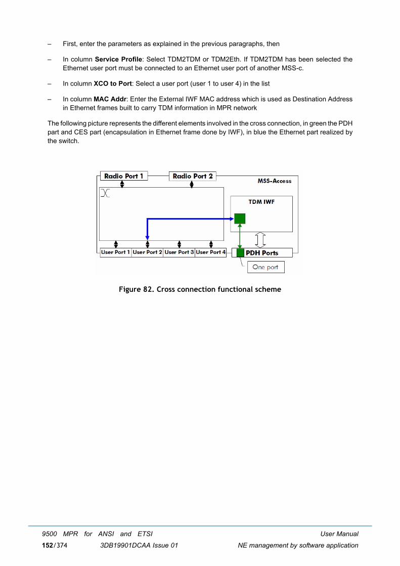
User Manual
NE management by software application
9500 MPR for ANSI and ETSI
3DB19901DCAA Issue 01152/374
� First, enter the parameters as explained in the previous paragraphs, then
� In column Service Profile: Select TDM2TDM or TDM2Eth. If TDM2TDM has been selected theEthernet user port must be connected to an Ethernet user port of another MSS-c.
� In column XCO to Port: Select a user port (user 1 to user 4) in the list
� In column MAC Addr: Enter the External IWF MAC address which is used as Destination Addressin Ethernet frames built to carry TDM information in MPR network
The following picture represents the different elements involved in the cross connection, in green the PDHpart and CES part (encapsulation in Ethernet frame done by IWF), in blue the Ethernet part realized bythe switch.
Figure 82. Cross connection functional scheme
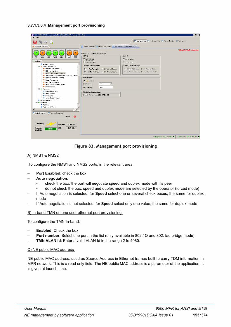
User Manual
NE management by software application
9500 MPR for ANSI and ETSI
3DB19901DCAA Issue 01 153/374
3.7.1.3.6.4 Management port provisioning
Figure 83. Management port provisioning
A) NMS1 & NMS2
To configure the NMS1 and NMS2 ports, in the relevant area:
� Port Enabled: check the box � Auto negotiation:
� check the box: the port will negotiate speed and duplex mode with its peer� do not check the box: speed and duplex mode are selected by the operator (forced mode)
� If Auto negotiation is selected, for Speed select one or several check boxes, the same for duplexmode
� If Auto negotiation is not selected, for Speed select only one value, the same for duplex mode
B) In-band TMN on one user ethernet port provisioning
To configure the TMN In-band:
� Enabled: Check the box� Port number: Select one port in the list (only available in 802.1Q and 802.1ad bridge mode).� TMN VLAN Id: Enter a valid VLAN Id in the range 2 to 4080.
C) NE public MAC address
NE public MAC address: used as Source Address in Ethernet frames built to carry TDM information inMPR network. This is a read only field. The NE public MAC address is a parameter of the application. Itis given at launch time.
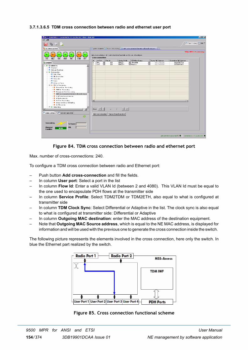
User Manual
NE management by software application
9500 MPR for ANSI and ETSI
3DB19901DCAA Issue 01154/374
3.7.1.3.6.5 TDM cross connection between radio and ethernet user port
Figure 84. TDM cross connection between radio and ethernet port
Max. number of cross-connections: 240.
To configure a TDM cross connection between radio and Ethernet port:
� Push button Add cross-connection and fill the fields. � In column User port: Select a port in the list � In column Flow Id: Enter a valid VLAN Id (between 2 and 4080). This VLAN Id must be equal to
the one used to encapsulate PDH flows at the transmitter side � In column Service Profile: Select TDM2TDM or TDM2ETH, also equal to what is configured at
transmitter side� In column TDM Clock Sync: Select Differential or Adaptive in the list. The clock sync is also equal
to what is configured at transmitter side: Differential or Adaptive � In column Outgoing MAC destination: enter the MAC address of the destination equipment. � Note that Outgoing MAC Source address, which is equal to the NE MAC address, is displayed for
information and will be used with the previous one to generate the cross connection inside the switch.
The following picture represents the elements involved in the cross connection, here only the switch. Inblue the Ethernet part realized by the switch.
Figure 85. Cross connection functional scheme
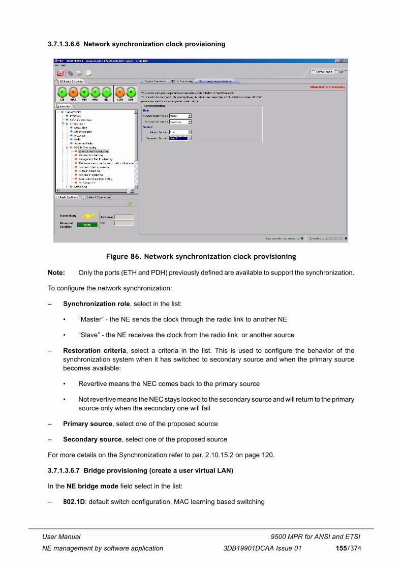
User Manual
NE management by software application
9500 MPR for ANSI and ETSI
3DB19901DCAA Issue 01 155/374
3.7.1.3.6.6 Network synchronization clock provisioning
Figure 86. Network synchronization clock provisioning
Note: Only the ports (ETH and PDH) previously defined are available to support the synchronization.
To configure the network synchronization:
� Synchronization role, select in the list:
� �Master� - the NE sends the clock through the radio link to another NE
� �Slave� - the NE receives the clock from the radio link or another source
� Restoration criteria, select a criteria in the list. This is used to configure the behavior of thesynchronization system when it has switched to secondary source and when the primary sourcebecomes available:
� Revertive means the NEC comes back to the primary source
� Not revertive means the NEC stays locked to the secondary source and will return to the primarysource only when the secondary one will fail
� Primary source, select one of the proposed source
� Secondary source, select one of the proposed source
For more details on the Synchronization refer to par. 2.10.15.2 on page 120.
3.7.1.3.6.7 Bridge provisioning (create a user virtual LAN)
In the NE bridge mode field select in the list:
� 802.1D: default switch configuration, MAC learning based switching
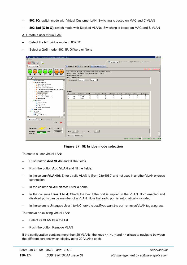
User Manual
NE management by software application
9500 MPR for ANSI and ETSI
3DB19901DCAA Issue 01156/374
� 802.1Q: switch mode with Virtual Customer LAN. Switching is based on MAC and C-VLAN
� 802.1ad (Q in Q): switch mode with Stacked VLANs. Switching is based on MAC and S-VLAN
A) Create a user virtual LAN
� Select the NE bridge mode in 802.1Q.
� Select a QoS mode: 802.1P, Diffserv or None
Figure 87. NE bridge mode selection
To create a user virtual LAN:
� Push button Add VLAN and fill the fields.
� Push the button Add VLAN and fill the fields.
� In the column VLAN Id: Enter a valid VLAN Id (from 2 to 4080) and not used in another VLAN or crossconnection
� In the column VLAN Name: Enter a name
� In the columns User 1 to 4: Check the box if the port is implied in the VLAN. Both enabled anddisabled ports can be member of a VLAN. Note that radio port is automatically included.
� In the columns Untagged User 1 to 4: Check the box if you want the port removes VLAN tag at egress.
To remove an existing virtual LAN:
� Select its VLAN Id in the list
� Push the button Remove VLAN
If the configuration contains more than 20 VLANs, the keys <<, <, > and >> allows to navigate betweenthe different screens which display up to 20 VLANs each.
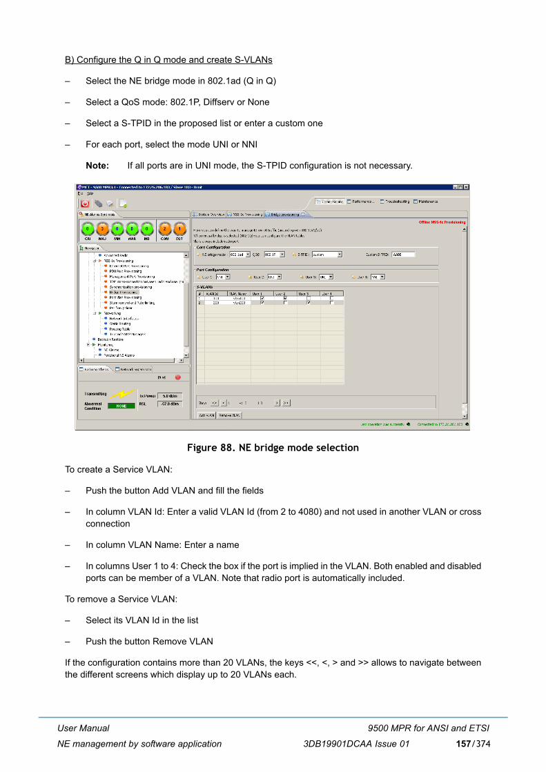
User Manual
NE management by software application
9500 MPR for ANSI and ETSI
3DB19901DCAA Issue 01 157/374
B) Configure the Q in Q mode and create S-VLANs
� Select the NE bridge mode in 802.1ad (Q in Q)
� Select a QoS mode: 802.1P, Diffserv or None
� Select a S-TPID in the proposed list or enter a custom one
� For each port, select the mode UNI or NNI
Note: If all ports are in UNI mode, the S-TPID configuration is not necessary.
Figure 88. NE bridge mode selection
To create a Service VLAN:
� Push the button Add VLAN and fill the fields
� In column VLAN Id: Enter a valid VLAN Id (from 2 to 4080) and not used in another VLAN or crossconnection
� In column VLAN Name: Enter a name
� In columns User 1 to 4: Check the box if the port is implied in the VLAN. Both enabled and disabledports can be member of a VLAN. Note that radio port is automatically included.
To remove a Service VLAN:
� Select its VLAN Id in the list
� Push the button Remove VLAN
If the configuration contains more than 20 VLANs, the keys <<, <, > and >> allows to navigate betweenthe different screens which display up to 20 VLANs each.
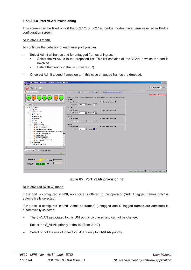
User Manual
NE management by software application
9500 MPR for ANSI and ETSI
3DB19901DCAA Issue 01158/374
3.7.1.3.6.8 Port VLAN Provisioning
This screen can be filled only if the 802.1Q or 802.1ad bridge modes have been selected in Bridgeconfiguration screen.
A) In 802.1Q mode
To configure the behavior of each user port you can:
� Select Admit all frames and for untagged frames at ingress: � Select the VLAN Id in the proposed list. This list contains all the VLAN in which the port is
involved.� Select the priority in the list (from 0 to 7)
� Or select Admit tagged frames only. In this case untagged frames are dropped.
Figure 89. Port VLAN provisioning
B) In 802.1ad (Q in Q) mode
If the port is configured in NNI, no choice is offered to the operator (�Admit tagged frames only� isautomatically selected).
If the port is configured in UNI �Admit all frames� (untagged and C-Tagged frames are admitted) isautomatically selected:
� The S-VLAN associated to this UNI port is displayed and cannot be changed
� Select the S_VLAN priority in the list (from 0 to 7)
� Select or not the use of inner C-VLAN priority for S-VLAN priority
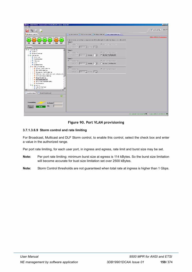
User Manual
NE management by software application
9500 MPR for ANSI and ETSI
3DB19901DCAA Issue 01 159/374
Figure 90. Port VLAN provisioning
3.7.1.3.6.9 Storm control and rate limiting
For Broadcast, Multicast and DLF Storm control, to enable this control, select the check box and entera value in the authorized range.
Per port rate limiting, for each user port, in ingress and egress, rate limit and burst size may be set.
Note: Per port rate limiting: minimum burst size at egress is 114 kBytes. So the burst size limitationwill become accurate for bust size limitation set over 2500 kBytes.
Note: Storm Control thresholds are not guaranteed when total rate at ingress is higher than 1 Gbps.
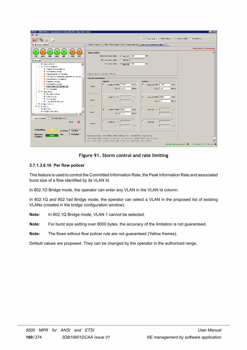
User Manual
NE management by software application
9500 MPR for ANSI and ETSI
3DB19901DCAA Issue 01160/374
Figure 91. Storm control and rate limiting
3.7.1.3.6.10 Per flow policer
This feature is used to control the Committed Information Rate, the Peak Information Rate and associatedburst size of a flow identified by its VLAN Id.
In 802.1D Bridge mode, the operator can enter any VLAN in the VLAN Id column.
In 802.1Q and 802.1ad Bridge mode, the operator can select a VLAN in the proposed list of existingVLANs (created in the bridge configuration window).
Note: In 802.1Q Bridge mode, VLAN 1 cannot be selected.
Note: For burst size setting over 8000 bytes, the accuracy of the limitation is not guaranteed.
Note: The flows without flow policer rule are not guaranteed (Yellow frames).
Default values are proposed. They can be changed by the operator in the authorized range.
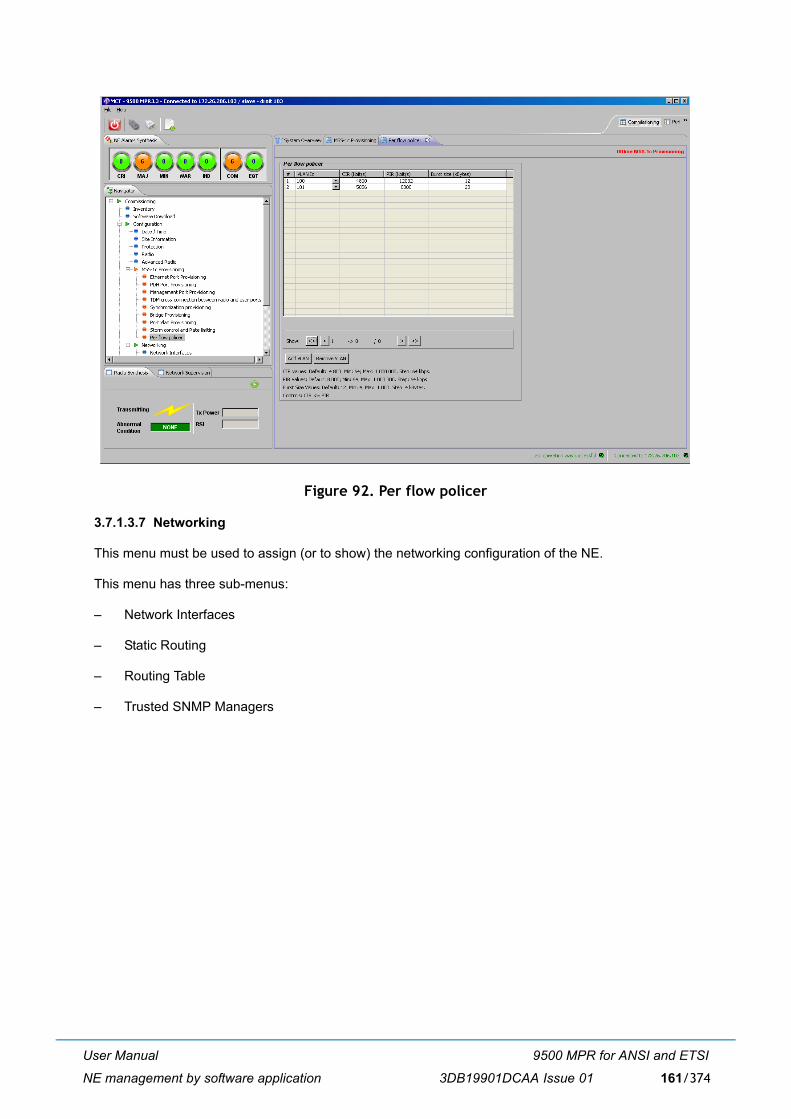
User Manual
NE management by software application
9500 MPR for ANSI and ETSI
3DB19901DCAA Issue 01 161/374
Figure 92. Per flow policer
3.7.1.3.7 Networking
This menu must be used to assign (or to show) the networking configuration of the NE.
This menu has three sub-menus:
� Network Interfaces
� Static Routing
� Routing Table
� Trusted SNMP Managers
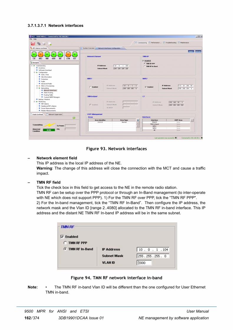
User Manual
NE management by software application
9500 MPR for ANSI and ETSI
3DB19901DCAA Issue 01162/374
3.7.1.3.7.1 Network interfaces
Figure 93. Network interfaces
� Network element fieldThis IP address is the local IP address of the NE.Warning: The change of this address will close the connection with the MCT and cause a trafficimpact.
� TMN RF fieldTick the check box in this field to get access to the NE in the remote radio station. TMN RF can be setup over the PPP protocol or through an In-Band management (to inter-operatewith NE which does not support PPP). 1) For the TMN RF over PPP, tick the �TMN RF PPP". 2) For the In-band management, tick the �TMN RF In-Band�. Then configure the IP address, thenetwork mask and the Vlan ID [range 2..4080] allocated to the TMN RF in-band interface. This IPaddress and the distant NE TMN RF In-band IP address will be in the same subnet.
Figure 94. TMN RF network interface in-band
Note: � The TMN RF in-band Vlan ID will be different than the one configured for User EthernetTMN in-band.
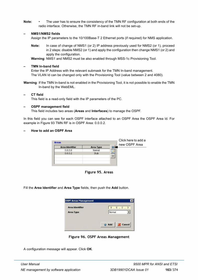
User Manual
NE management by software application
9500 MPR for ANSI and ETSI
3DB19901DCAA Issue 01 163/374
Note: � The user has to ensure the consistency of the TMN RF configuration at both ends of theradio interface. Otherwise, the TMN RF in-band link will not be set-up.
� NMS1/NMS2 fieldsAssign the IP parameters to the 10/100Base-T 2 Ethernet ports (if required) for NMS application.
Note: In case of change of NMS1 (or 2) IP address previously used for NMS2 (or 1), proceedin 2 steps: disable NMS2 (or 1) and apply the configuration then change NMS1 (or 2) andapply the configuration.
Warning: NMS1 and NMS2 must be also enabled through MSS-1c Provisioning Tool.
� TMN In-band fieldEnter the IP Address with the relevant submask for the TMN In-band management.The VLAN Id can be changed only with the Provisioning Tool (value between 2 and 4080).
Warning: If the TMN In-band is not enabled in the Provisioning Tool, it is not possible to enable the TMNIn-band by the WebEML.
� CT fieldThis field is a read-only field with the IP parameters of the PC.
� OSPF management fieldThis field includes two areas (Areas and Interfaces) to manage the OSPF.
In this field you can see for each OSPF interface attached to an OSPF Area the OSPF Area Id. Forexample in Figure 93 TMN RF is in OSPF Area: 0.0.0.2.
� How to add an OSPF Area
Figure 95. Areas
Fill the Area Identifier and Area Type fields, then push the Add button.
Figure 96. OSPF Areas Management
A configuration message will appear. Click OK.
Click here to add anew OSPF Area
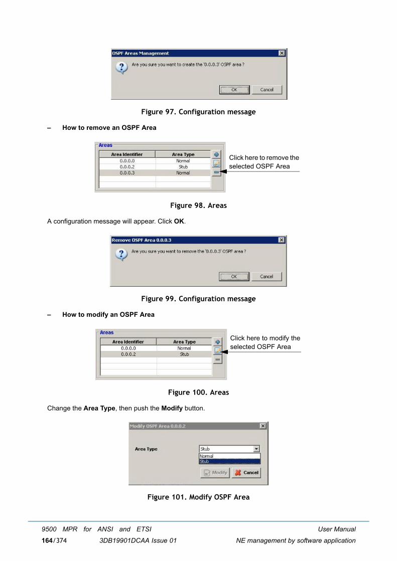
User Manual
NE management by software application
9500 MPR for ANSI and ETSI
3DB19901DCAA Issue 01164/374
Figure 97. Configuration message
� How to remove an OSPF Area
Figure 98. Areas
A configuration message will appear. Click OK.
Figure 99. Configuration message
� How to modify an OSPF Area
Figure 100. Areas
Change the Area Type, then push the Modify button.
Figure 101. Modify OSPF Area
Click here to remove theselected OSPF Area
Click here to modify theselected OSPF Area
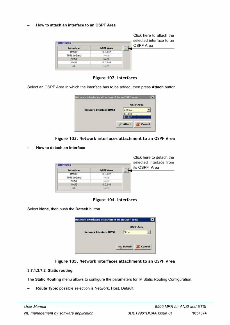
User Manual
NE management by software application
9500 MPR for ANSI and ETSI
3DB19901DCAA Issue 01 165/374
� How to attach an interface to an OSPF Area
Figure 102. Interfaces
Select an OSPF Area in which the interface has to be added, then press Attach button.
Figure 103. Network interfaces attachment to an OSPF Area
� How to detach an interface
Figure 104. Interfaces
Select None, then push the Detach button.
Figure 105. Network interfaces attachment to an OSPF Area
3.7.1.3.7.2 Static routing
The Static Routing menu allows to configure the parameters for IP Static Routing Configuration.
� Route Type: possible selection is Network, Host, Default.
Click here to attach theselected interface to anOSPF Area
Click here to detach theselected interface fromits OSPF Area
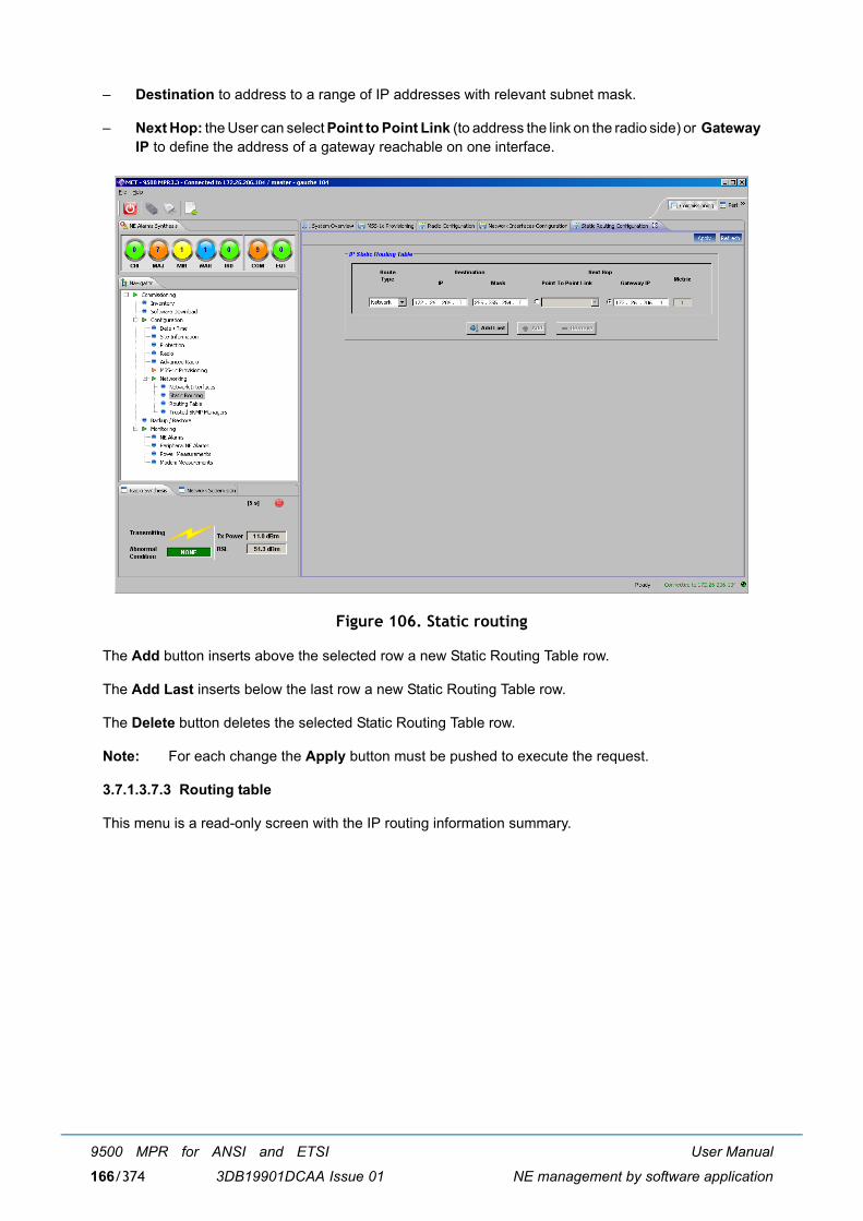
User Manual
NE management by software application
9500 MPR for ANSI and ETSI
3DB19901DCAA Issue 01166/374
� Destination to address to a range of IP addresses with relevant subnet mask.
� Next Hop: the User can select Point to Point Link (to address the link on the radio side) or GatewayIP to define the address of a gateway reachable on one interface.
Figure 106. Static routing
The Add button inserts above the selected row a new Static Routing Table row.
The Add Last inserts below the last row a new Static Routing Table row.
The Delete button deletes the selected Static Routing Table row.
Note: For each change the Apply button must be pushed to execute the request.
3.7.1.3.7.3 Routing table
This menu is a read-only screen with the IP routing information summary.
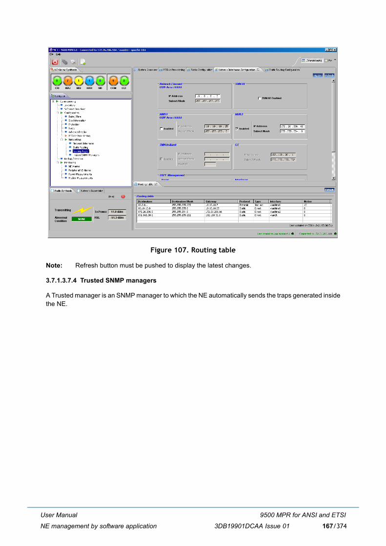
User Manual
NE management by software application
9500 MPR for ANSI and ETSI
3DB19901DCAA Issue 01 167/374
Figure 107. Routing table
Note: Refresh button must be pushed to display the latest changes.
3.7.1.3.7.4 Trusted SNMP managers
A Trusted manager is an SNMP manager to which the NE automatically sends the traps generated insidethe NE.

User Manual
NE management by software application
9500 MPR for ANSI and ETSI
3DB19901DCAA Issue 01168/374
Figure 108. Trusted SNMP managers
To activate a Trusted Manager insert the IP Address of the SNMP manager, the Traps UDP Port andthe Manager Type (Network Manager Layer or Equipment Manager Layer), then click on Register.
Note about the Manager Type:
� �Network Manager Layer� must be used for 5620 SAM and other NMS system.
� �Equipment Manager Layer� must be used for 1350 OMS system type (where the "alarm type" fieldis removed from the alarm traps) when automatic registration of the manager is not possible
Note: The "Traps UDP port" corresponds to the port on which the Manager receives the traps.
In Figure 109. one Manager has been created.
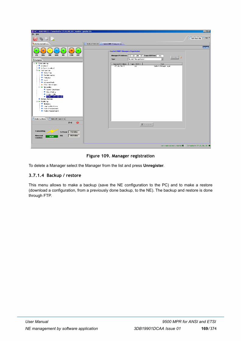
User Manual
NE management by software application
9500 MPR for ANSI and ETSI
3DB19901DCAA Issue 01 169/374
Figure 109. Manager registration
To delete a Manager select the Manager from the list and press Unregister.
3.7.1.4 Backup / restore
This menu allows to make a backup (save the NE configuration to the PC) and to make a restore(download a configuration, from a previously done backup, to the NE). The backup and restore is donethrough FTP.
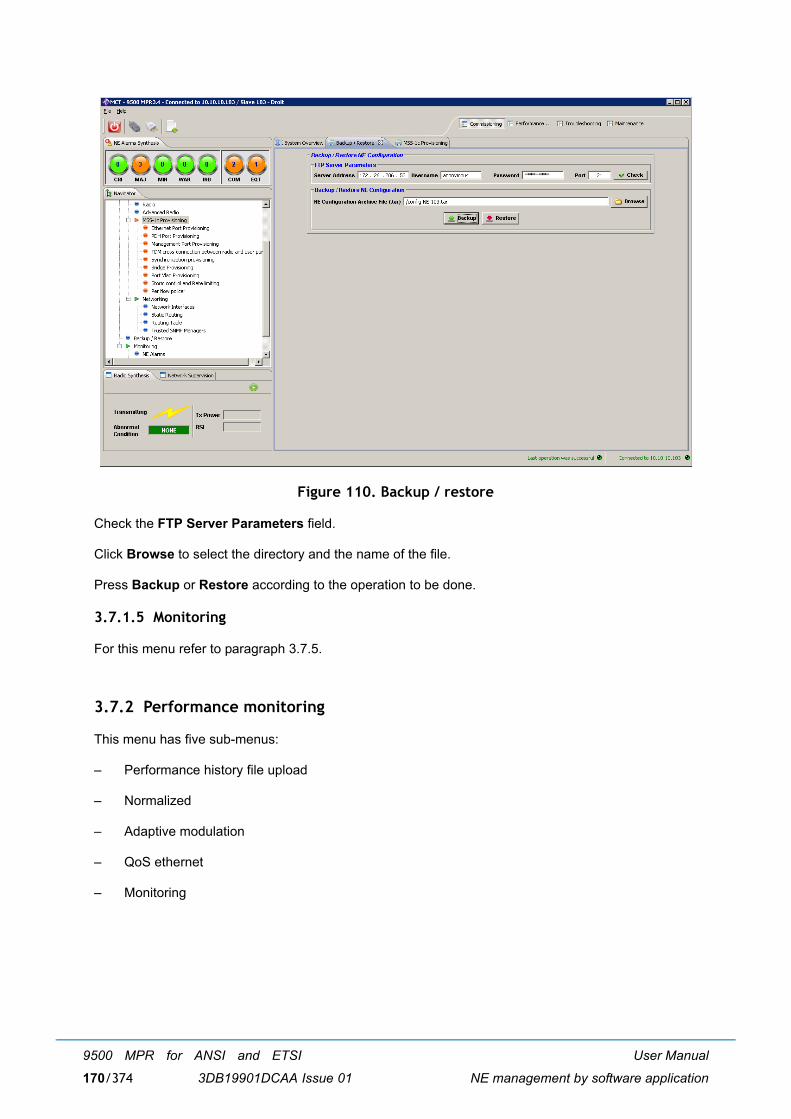
User Manual
NE management by software application
9500 MPR for ANSI and ETSI
3DB19901DCAA Issue 01170/374
Figure 110. Backup / restore
Check the FTP Server Parameters field.
Click Browse to select the directory and the name of the file.
Press Backup or Restore according to the operation to be done.
3.7.1.5 Monitoring
For this menu refer to paragraph 3.7.5.
3.7.2 Performance monitoring
This menu has five sub-menus:
� Performance history file upload
� Normalized
� Adaptive modulation
� QoS ethernet
� Monitoring

User Manual
NE management by software application
9500 MPR for ANSI and ETSI
3DB19901DCAA Issue 01 171/374
3.7.2.1 Performance history file upload
This menu allows to export in a .csv file the data regarding the performance counters. This operation isdone through an FTP session.
� Check the FTP Server Parameters area with the FTP Server parameters.
� Select in the Performance History Parameters field the type of counters to be exported:Normalized Performance Counters (refer to par. 3.7.2.2) / Adaptive Modulation Counters (refer topar. 3.7.2.3) / QoS Ethernet Counters (refer to par. 3.7.2.4.1).
Note: The counters to be exported must be stopped (refer to the relevant paragraphs).
Note: The counters use GMT timestamps.
� Select the History Period (in second - default: 5s - for the QoS Ethernet Counters; 15 m or 24 h forthe Normalized and Adaptive counters) and click Apply.
� Click on Browse to choose the destination directory and to assign the name of the file.
� Click on Upload History to export the file.
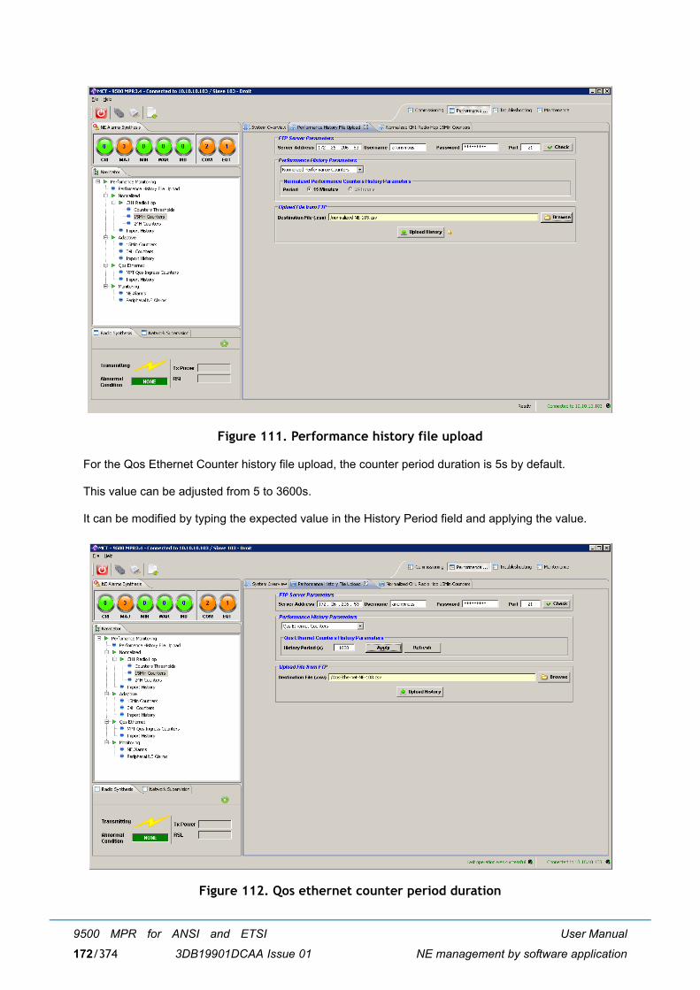
User Manual
NE management by software application
9500 MPR for ANSI and ETSI
3DB19901DCAA Issue 01172/374
Figure 111. Performance history file upload
For the Qos Ethernet Counter history file upload, the counter period duration is 5s by default.
This value can be adjusted from 5 to 3600s.
It can be modified by typing the expected value in the History Period field and applying the value.
Figure 112. Qos ethernet counter period duration
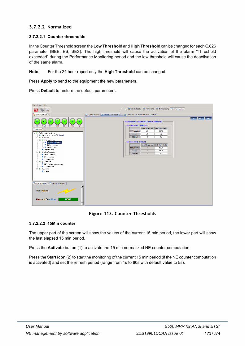
User Manual
NE management by software application
9500 MPR for ANSI and ETSI
3DB19901DCAA Issue 01 173/374
3.7.2.2 Normalized
3.7.2.2.1 Counter thresholds
In the Counter Threshold screen the Low Threshold and High Threshold can be changed for each G.826parameter (BBE, ES, SES). The high threshold will cause the activation of the alarm "Thresholdexceeded" during the Performance Monitoring period and the low threshold will cause the deactivationof the same alarm.
Note: For the 24 hour report only the High Threshold can be changed.
Press Apply to send to the equipment the new parameters.
Press Default to restore the default parameters.
Figure 113. Counter Thresholds
3.7.2.2.2 15Min counter
The upper part of the screen will show the values of the current 15 min period, the lower part will showthe last elapsed 15 min period.
Press the Activate button (1) to activate the 15 min normalized NE counter computation.
Press the Start icon (2) to start the monitoring of the current 15 min period (if the NE counter computationis activated) and set the refresh period (range from 1s to 60s with default value to 5s).
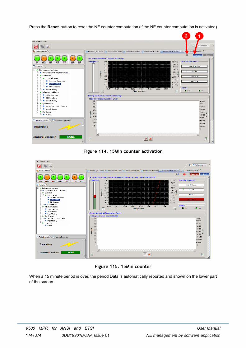
User Manual
NE management by software application
9500 MPR for ANSI and ETSI
3DB19901DCAA Issue 01174/374
Press the Reset button to reset the NE counter computation (if the NE counter computation is activated)
Figure 114. 15Min counter activation
Figure 115. 15Min counter
When a 15 minute period is over, the period Data is automatically reported and shown on the lower partof the screen.
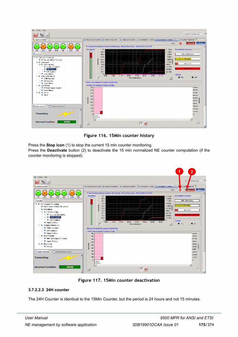
User Manual
NE management by software application
9500 MPR for ANSI and ETSI
3DB19901DCAA Issue 01 175/374
Figure 116. 15Min counter history
Press the Stop icon (1) to stop the current 15 min counter monitoring.Press the Deactivate button (2) to deactivate the 15 min normalized NE counter computation (if thecounter monitoring is stopped).
Figure 117. 15Min counter deactivation
3.7.2.2.3 24H counter
The 24H Counter is identical to the 15Min Counter, but the period is 24 hours and not 15 minutes.
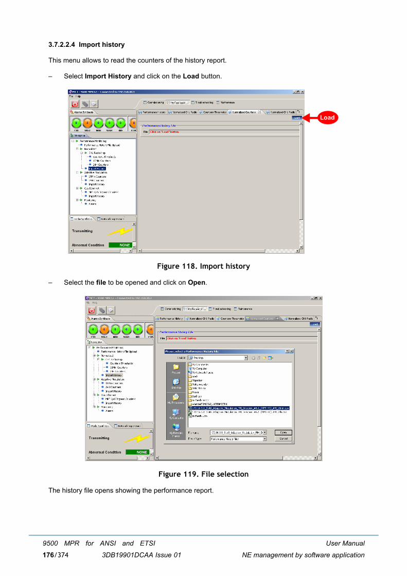
User Manual
NE management by software application
9500 MPR for ANSI and ETSI
3DB19901DCAA Issue 01176/374
3.7.2.2.4 Import history
This menu allows to read the counters of the history report.
� Select Import History and click on the Load button.
Figure 118. Import history
� Select the file to be opened and click on Open.
Figure 119. File selection
The history file opens showing the performance report.
Load
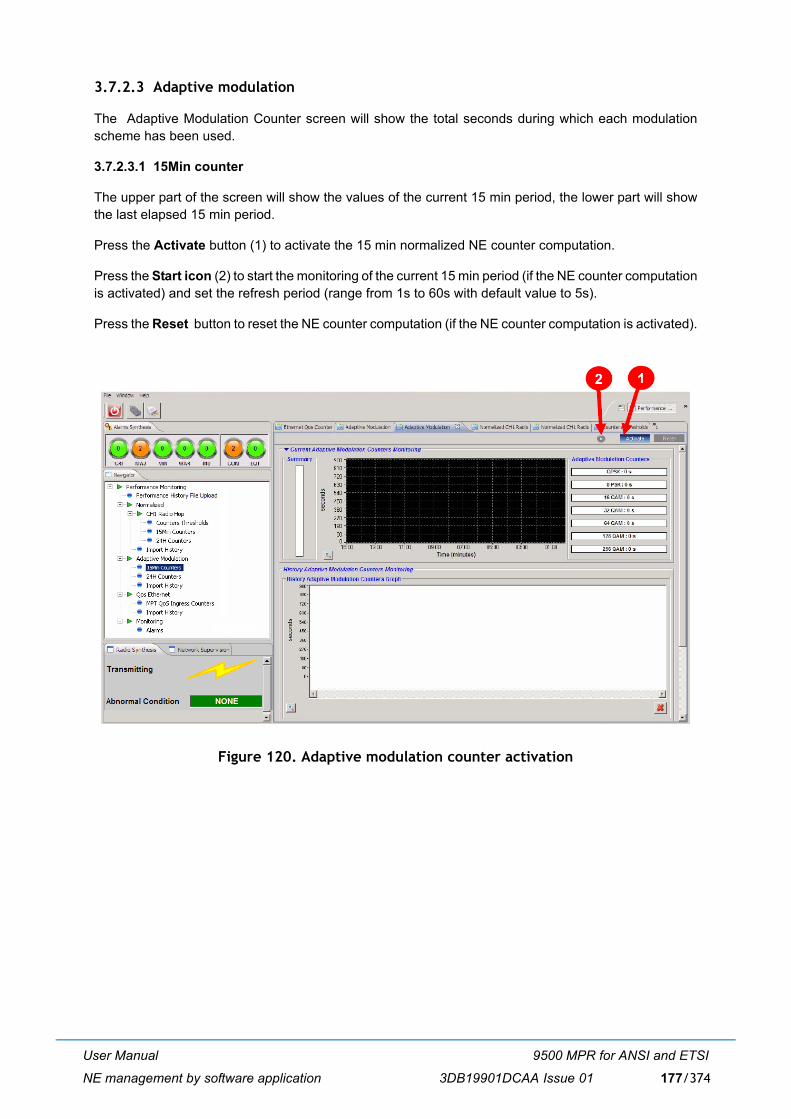
User Manual
NE management by software application
9500 MPR for ANSI and ETSI
3DB19901DCAA Issue 01 177/374
3.7.2.3 Adaptive modulation
The Adaptive Modulation Counter screen will show the total seconds during which each modulationscheme has been used.
3.7.2.3.1 15Min counter
The upper part of the screen will show the values of the current 15 min period, the lower part will showthe last elapsed 15 min period.
Press the Activate button (1) to activate the 15 min normalized NE counter computation.
Press the Start icon (2) to start the monitoring of the current 15 min period (if the NE counter computationis activated) and set the refresh period (range from 1s to 60s with default value to 5s).
Press the Reset button to reset the NE counter computation (if the NE counter computation is activated).
Figure 120. Adaptive modulation counter activation
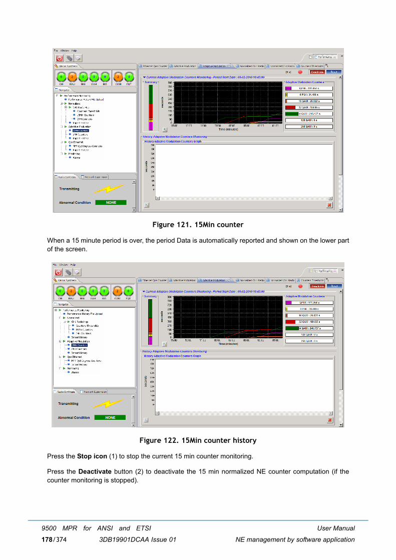
User Manual
NE management by software application
9500 MPR for ANSI and ETSI
3DB19901DCAA Issue 01178/374
Figure 121. 15Min counter
When a 15 minute period is over, the period Data is automatically reported and shown on the lower partof the screen.
Figure 122. 15Min counter history
Press the Stop icon (1) to stop the current 15 min counter monitoring.
Press the Deactivate button (2) to deactivate the 15 min normalized NE counter computation (if thecounter monitoring is stopped).
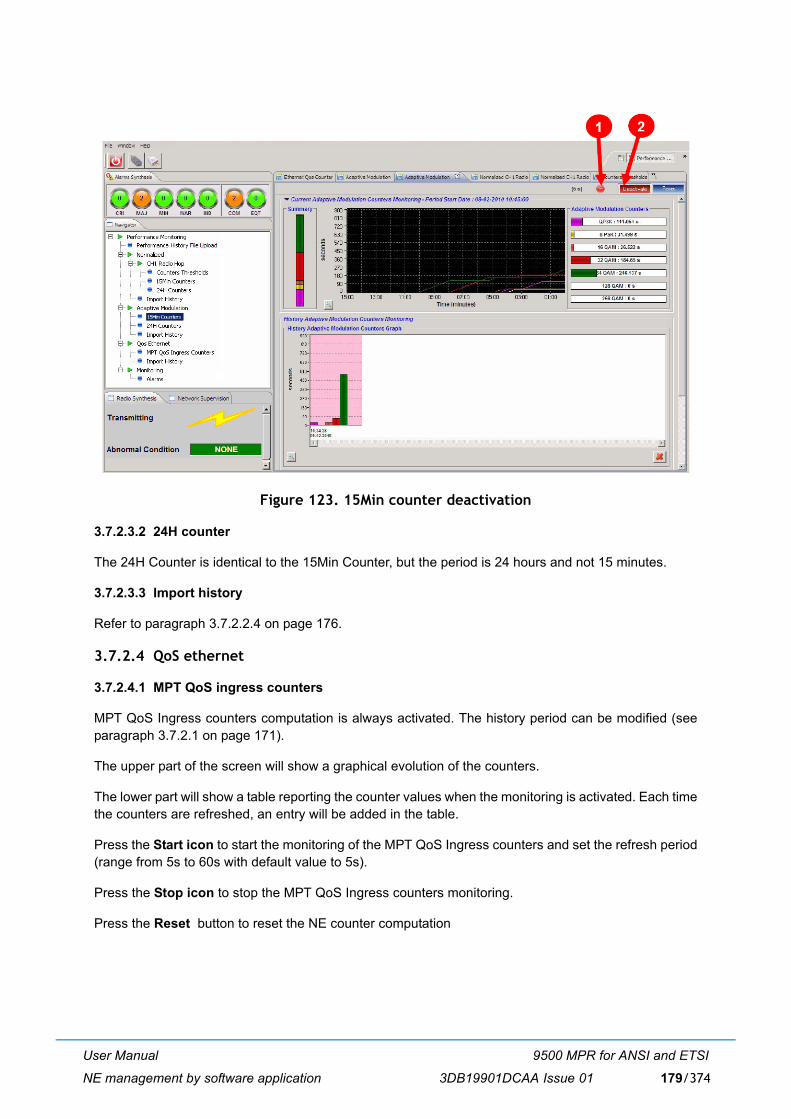
User Manual
NE management by software application
9500 MPR for ANSI and ETSI
3DB19901DCAA Issue 01 179/374
Figure 123. 15Min counter deactivation
3.7.2.3.2 24H counter
The 24H Counter is identical to the 15Min Counter, but the period is 24 hours and not 15 minutes.
3.7.2.3.3 Import history
Refer to paragraph 3.7.2.2.4 on page 176.
3.7.2.4 QoS ethernet
3.7.2.4.1 MPT QoS ingress counters
MPT QoS Ingress counters computation is always activated. The history period can be modified (seeparagraph 3.7.2.1 on page 171).
The upper part of the screen will show a graphical evolution of the counters.
The lower part will show a table reporting the counter values when the monitoring is activated. Each timethe counters are refreshed, an entry will be added in the table.
Press the Start icon to start the monitoring of the MPT QoS Ingress counters and set the refresh period(range from 5s to 60s with default value to 5s).
Press the Stop icon to stop the MPT QoS Ingress counters monitoring.
Press the Reset button to reset the NE counter computation
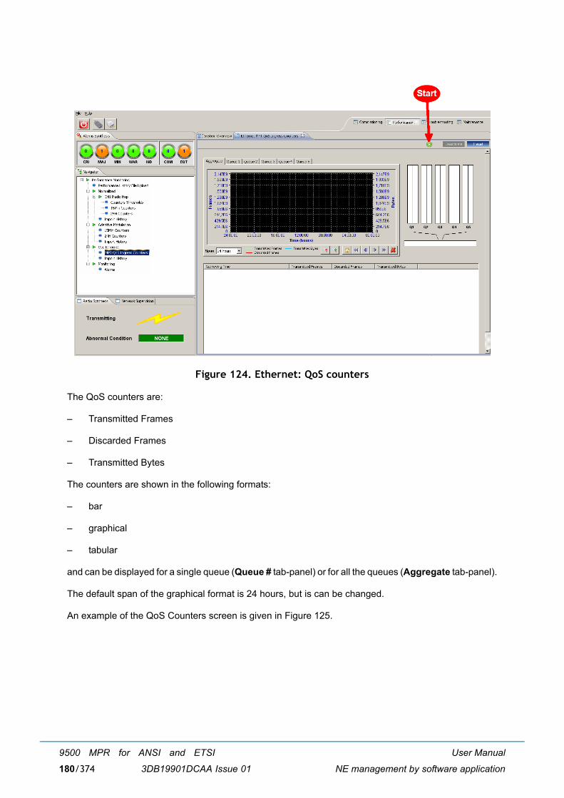
User Manual
NE management by software application
9500 MPR for ANSI and ETSI
3DB19901DCAA Issue 01180/374
Figure 124. Ethernet: QoS counters
The QoS counters are:
� Transmitted Frames
� Discarded Frames
� Transmitted Bytes
The counters are shown in the following formats:
� bar
� graphical
� tabular
and can be displayed for a single queue (Queue # tab-panel) or for all the queues (Aggregate tab-panel).
The default span of the graphical format is 24 hours, but is can be changed.
An example of the QoS Counters screen is given in Figure 125.
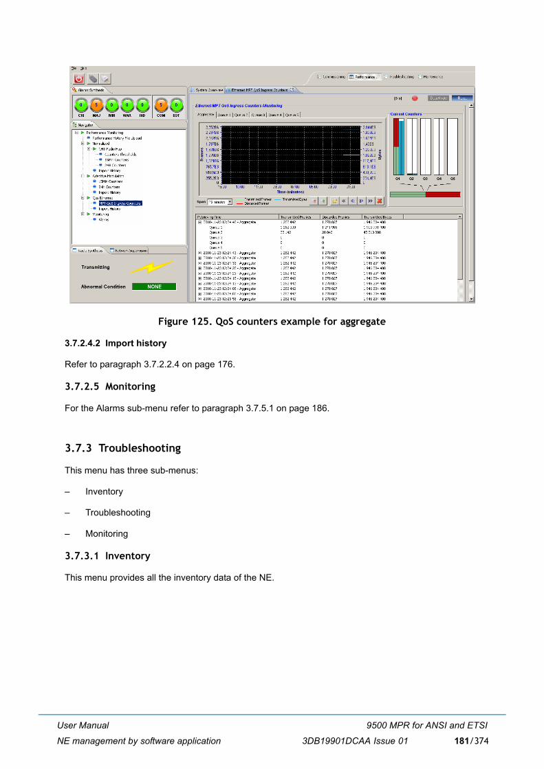
User Manual
NE management by software application
9500 MPR for ANSI and ETSI
3DB19901DCAA Issue 01 181/374
Figure 125. QoS counters example for aggregate
3.7.2.4.2 Import history
Refer to paragraph 3.7.2.2.4 on page 176.
3.7.2.5 Monitoring
For the Alarms sub-menu refer to paragraph 3.7.5.1 on page 186.
3.7.3 Troubleshooting
This menu has three sub-menus:
� Inventory
� Troubleshooting
� Monitoring
3.7.3.1 Inventory
This menu provides all the inventory data of the NE.
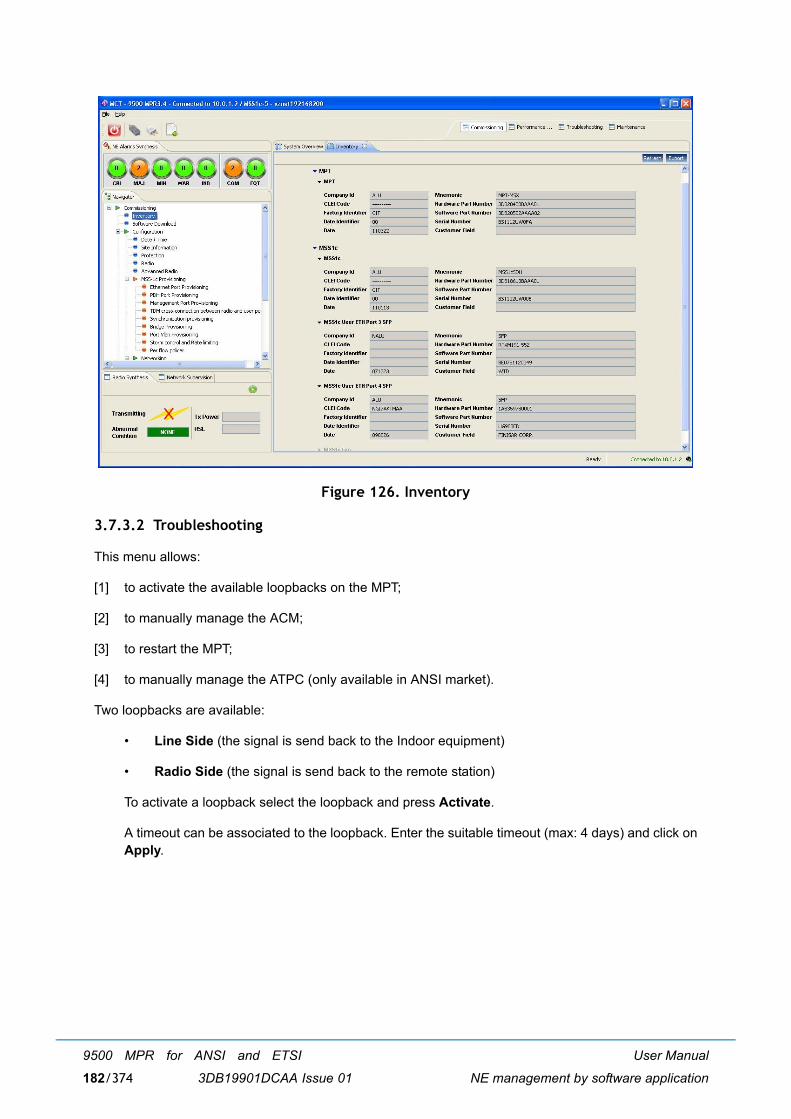
User Manual
NE management by software application
9500 MPR for ANSI and ETSI
3DB19901DCAA Issue 01182/374
Figure 126. Inventory
3.7.3.2 Troubleshooting
This menu allows:
[1] to activate the available loopbacks on the MPT;
[2] to manually manage the ACM;
[3] to restart the MPT;
[4] to manually manage the ATPC (only available in ANSI market).
Two loopbacks are available:
� Line Side (the signal is send back to the Indoor equipment)
� Radio Side (the signal is send back to the remote station)
To activate a loopback select the loopback and press Activate.
A timeout can be associated to the loopback. Enter the suitable timeout (max: 4 days) and click onApply.
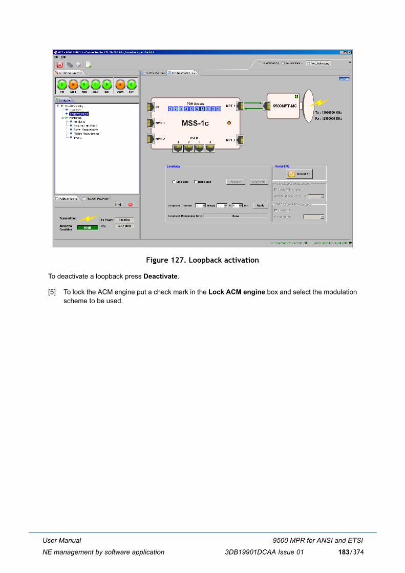
User Manual
NE management by software application
9500 MPR for ANSI and ETSI
3DB19901DCAA Issue 01 183/374
Figure 127. Loopback activation
To deactivate a loopback press Deactivate.
[5] To lock the ACM engine put a check mark in the Lock ACM engine box and select the modulationscheme to be used.
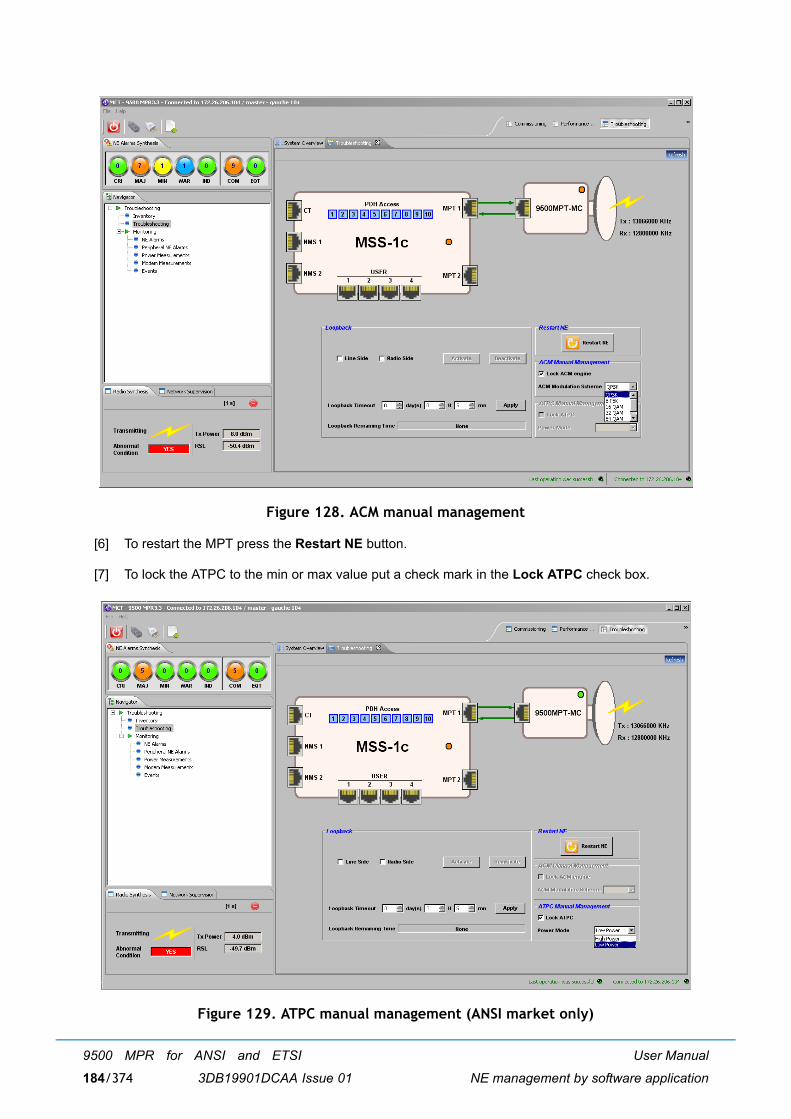
User Manual
NE management by software application
9500 MPR for ANSI and ETSI
3DB19901DCAA Issue 01184/374
Figure 128. ACM manual management
[6] To restart the MPT press the Restart NE button.
[7] To lock the ATPC to the min or max value put a check mark in the Lock ATPC check box.
Figure 129. ATPC manual management (ANSI market only)
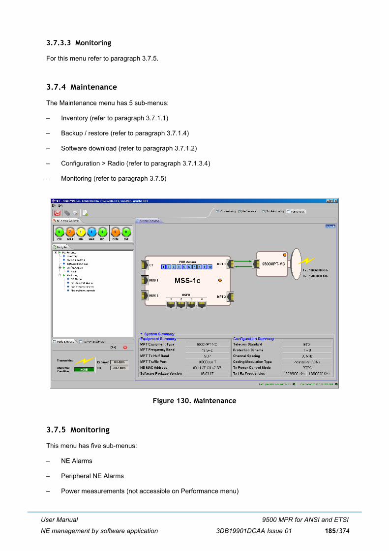
User Manual
NE management by software application
9500 MPR for ANSI and ETSI
3DB19901DCAA Issue 01 185/374
3.7.3.3 Monitoring
For this menu refer to paragraph 3.7.5.
3.7.4 Maintenance
The Maintenance menu has 5 sub-menus:
� Inventory (refer to paragraph 3.7.1.1)
� Backup / restore (refer to paragraph 3.7.1.4)
� Software download (refer to paragraph 3.7.1.2)
� Configuration > Radio (refer to paragraph 3.7.1.3.4)
� Monitoring (refer to paragraph 3.7.5)
Figure 130. Maintenance
3.7.5 Monitoring
This menu has five sub-menus:
� NE Alarms
� Peripheral NE Alarms
� Power measurements (not accessible on Performance menu)

User Manual
NE management by software application
9500 MPR for ANSI and ETSI
3DB19901DCAA Issue 01186/374
� Modem measurements (not accessible on Performance menu)
� Events (only in the Troubleshooting menu)
3.7.5.1 NE Alarms
The NE Alarms menu allow you to display and store the alarms of the NE.
Two global lists of alarms are displayed:
� CURRENT ALARMS shows all the equipment alarms currently present,
� ALARM LOG shows all the equipment alarms currently present and the history of the alarms (i.e.cleared alarms).
Note: When an alarm is no longer active it disappears from the Current Alarm list and it is displayed in the Alarm log list as a cleared alarm
Note: The alarms present when the system is powered on are not reported on Alarm Log
The alarms have a different color according to their severity and their state.
� Red: CRITICAL alarm
� Orange: MAJOR alarm
� Yellow: MINOR alarm
� Cyan: WARNING alarm
� Blue: INDETERMINATE alarm (Note that the equipment has no alarm having such severity)
� Green: CLEARED alarm (alarm no longer active).
You can apply filters on this list of alarms.
Within the tab-panel, each alarm is provided with the information below.
� Time Stamp: date and time of the alarm. The format of date and time is yyyy/mm/dd hh:mm:ss.
� Probable Cause: name of the probable cause of the alarm.
� Type: alarm class (COMMUNICATION � alarm not created inside the equipment, but generated bya connected equipment or due to transmission/propagation problems; EQUIPMENT: inside alarm ofthe equipment).
� Object: object of the equipment where the alarm occurred.
� SubObject: sub object of the equipment where the alarm occurred.
� Severity: alarm severity.
� Specific Problem: this field gives more information regarding the alarm.
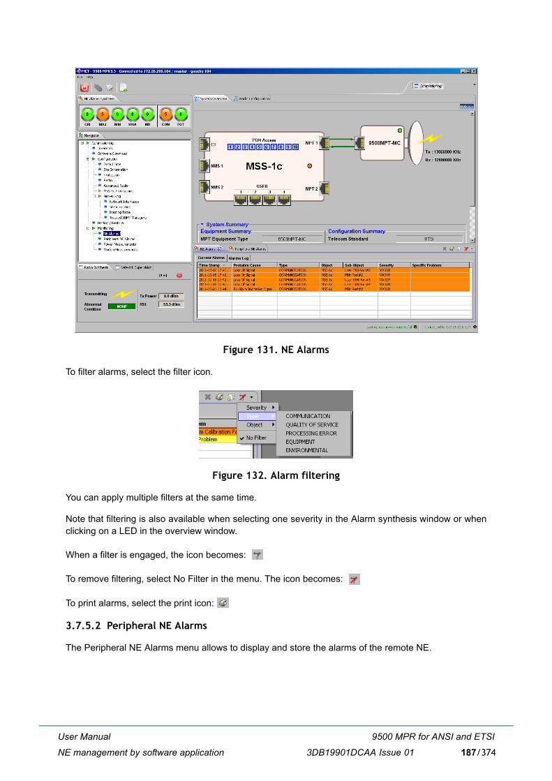
User Manual
NE management by software application
9500 MPR for ANSI and ETSI
3DB19901DCAA Issue 01 187/374
Figure 131. NE Alarms
To filter alarms, select the filter icon.
Figure 132. Alarm filtering
You can apply multiple filters at the same time.
Note that filtering is also available when selecting one severity in the Alarm synthesis window or whenclicking on a LED in the overview window.
When a filter is engaged, the icon becomes:
To remove filtering, select No Filter in the menu. The icon becomes:
To print alarms, select the print icon:
3.7.5.2 Peripheral NE Alarms
The Peripheral NE Alarms menu allows to display and store the alarms of the remote NE.
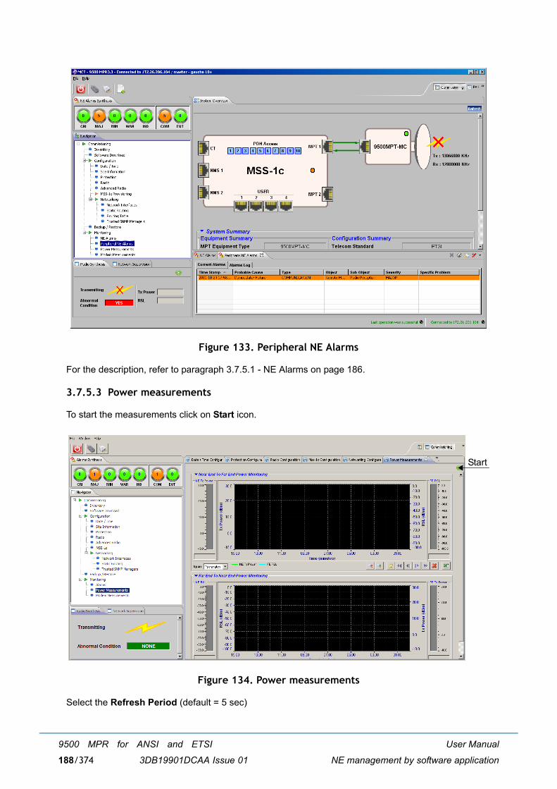
User Manual
NE management by software application
9500 MPR for ANSI and ETSI
3DB19901DCAA Issue 01188/374
Figure 133. Peripheral NE Alarms
For the description, refer to paragraph 3.7.5.1 - NE Alarms on page 186.
3.7.5.3 Power measurements
To start the measurements click on Start icon.
Figure 134. Power measurements
Select the Refresh Period (default = 5 sec)
Start

User Manual
NE management by software application
9500 MPR for ANSI and ETSI
3DB19901DCAA Issue 01 189/374
Note: Without any received signal (Tx mute on the remote MPT for example), the RSL value displayedmay be more than -100dBm. This depends of the channelisation/modulation settings.
Figure 135. Power measurements
The screen is divided in two parts, relevant to the two radio hop directions:
� Near End To Far End Power Monitoring (upper part)
� Far End To Near End Power Monitoring (lower part)
The bar indications and the curves, regarding the Tx Power and the Rx signal (RSL), are shown for eachdirection. The Span of the curve can be changed.
Available buttons from the left to the right side:
� Zoom Out
� Zoom In
� Scroll Lock
� Left and right arrows (4 buttons) to navigate in the curve
� Erase to erase the curves
� Export to create an Excel file to store the Power measurements.
To stop the measurements press the Stop icon on the upper right corner.
Stop
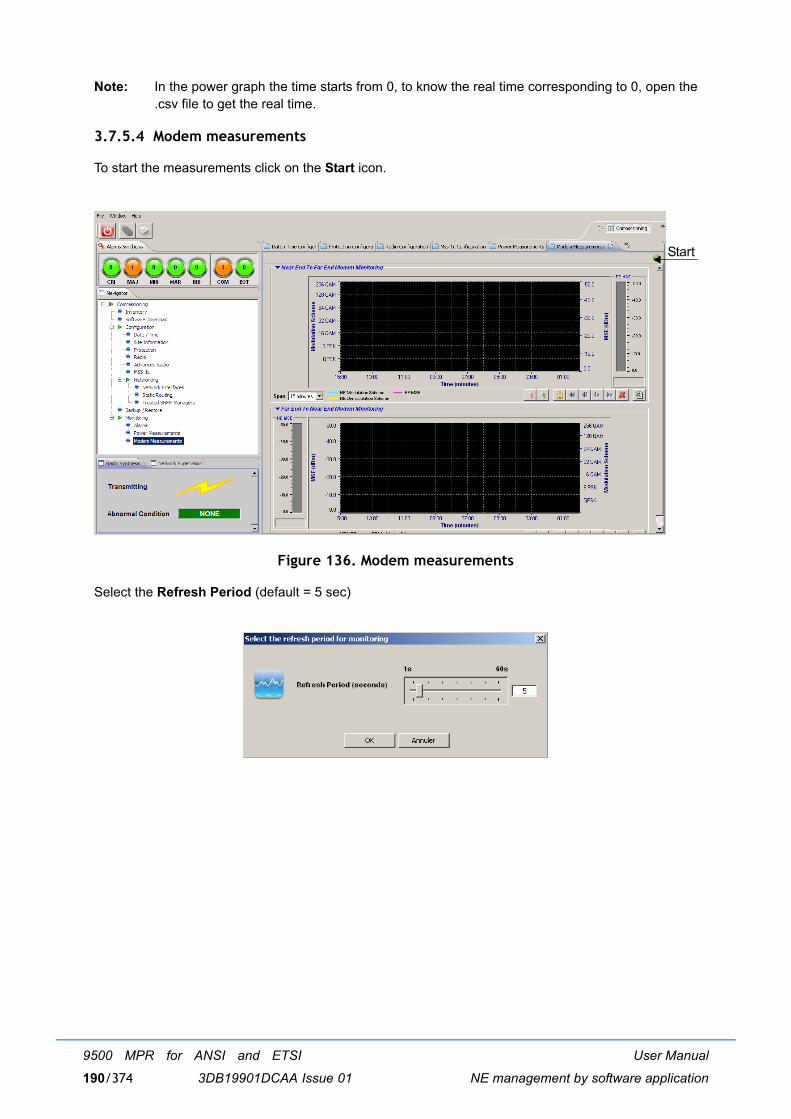
User Manual
NE management by software application
9500 MPR for ANSI and ETSI
3DB19901DCAA Issue 01190/374
Note: In the power graph the time starts from 0, to know the real time corresponding to 0, open the.csv file to get the real time.
3.7.5.4 Modem measurements
To start the measurements click on the Start icon.
Figure 136. Modem measurements
Select the Refresh Period (default = 5 sec)
Start
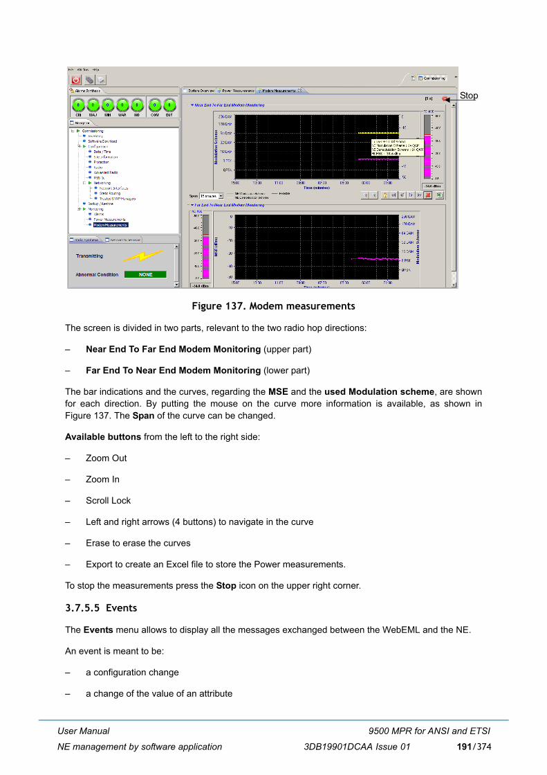
User Manual
NE management by software application
9500 MPR for ANSI and ETSI
3DB19901DCAA Issue 01 191/374
Figure 137. Modem measurements
The screen is divided in two parts, relevant to the two radio hop directions:
� Near End To Far End Modem Monitoring (upper part)
� Far End To Near End Modem Monitoring (lower part)
The bar indications and the curves, regarding the MSE and the used Modulation scheme, are shownfor each direction. By putting the mouse on the curve more information is available, as shown inFigure 137. The Span of the curve can be changed.
Available buttons from the left to the right side:
� Zoom Out
� Zoom In
� Scroll Lock
� Left and right arrows (4 buttons) to navigate in the curve
� Erase to erase the curves
� Export to create an Excel file to store the Power measurements.
To stop the measurements press the Stop icon on the upper right corner.
3.7.5.5 Events
The Events menu allows to display all the messages exchanged between the WebEML and the NE.
An event is meant to be:
� a configuration change
� a change of the value of an attribute
Stop
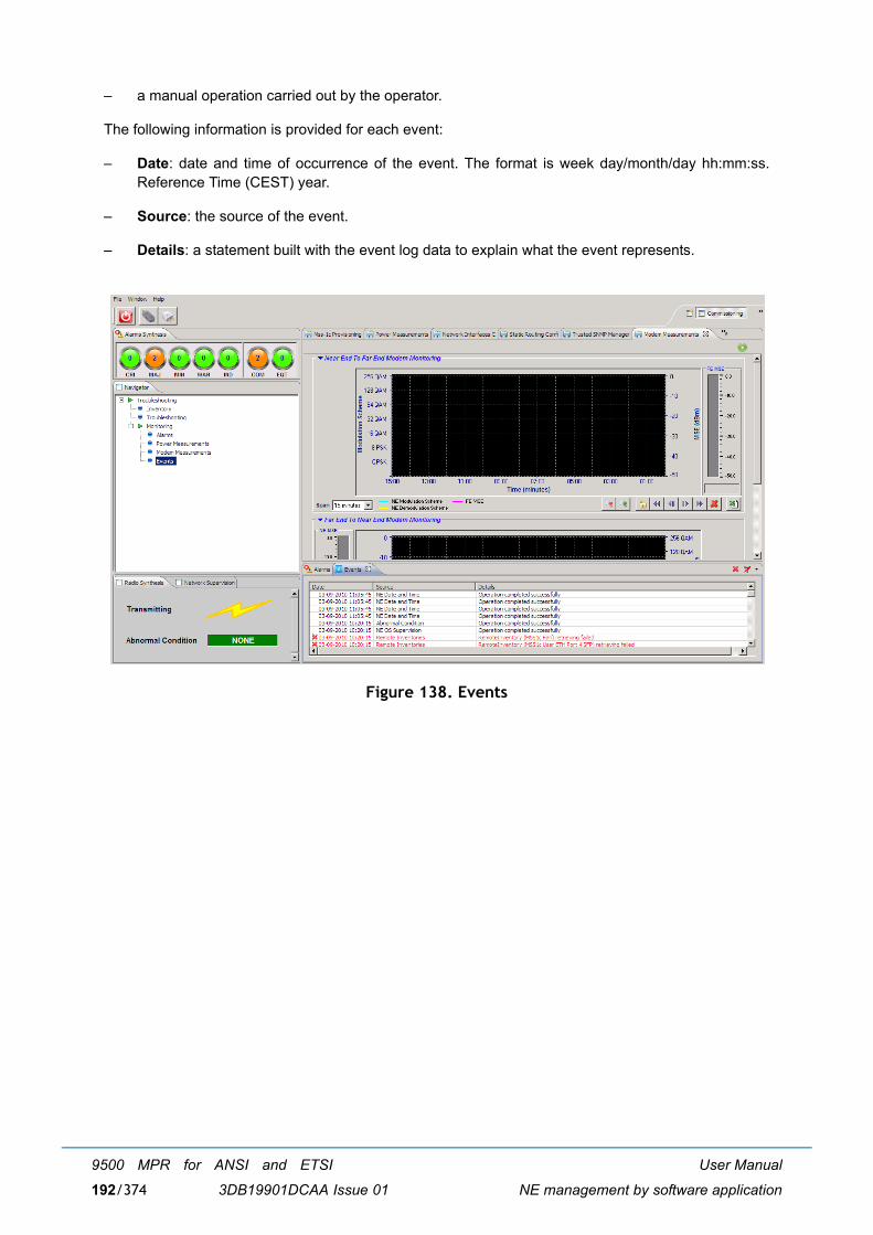
User Manual
NE management by software application
9500 MPR for ANSI and ETSI
3DB19901DCAA Issue 01192/374
� a manual operation carried out by the operator.
The following information is provided for each event:
� Date: date and time of occurrence of the event. The format is week day/month/day hh:mm:ss.Reference Time (CEST) year.
� Source: the source of the event.
� Details: a statement built with the event log data to explain what the event represents.
Figure 138. Events
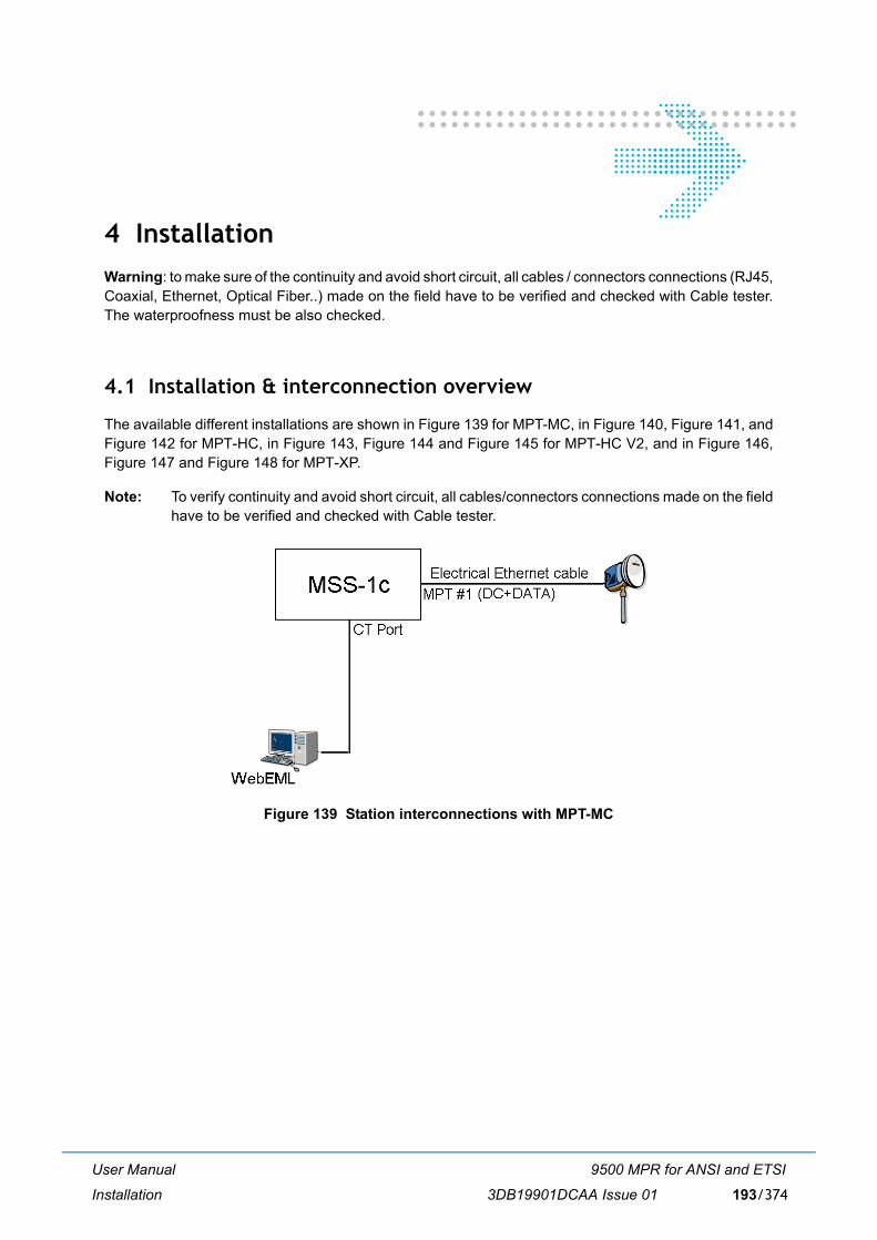
User Manual
Installation
9500 MPR for ANSI and ETSI
3DB19901DCAA Issue 01 193/374
4 InstallationWarning: to make sure of the continuity and avoid short circuit, all cables / connectors connections (RJ45,Coaxial, Ethernet, Optical Fiber..) made on the field have to be verified and checked with Cable tester.The waterproofness must be also checked.
4.1 Installation & interconnection overview
The available different installations are shown in Figure 139 for MPT-MC, in Figure 140, Figure 141, andFigure 142 for MPT-HC, in Figure 143, Figure 144 and Figure 145 for MPT-HC V2, and in Figure 146,Figure 147 and Figure 148 for MPT-XP.
Note: To verify continuity and avoid short circuit, all cables/connectors connections made on the fieldhave to be verified and checked with Cable tester.
Figure 139 Station interconnections with MPT-MC
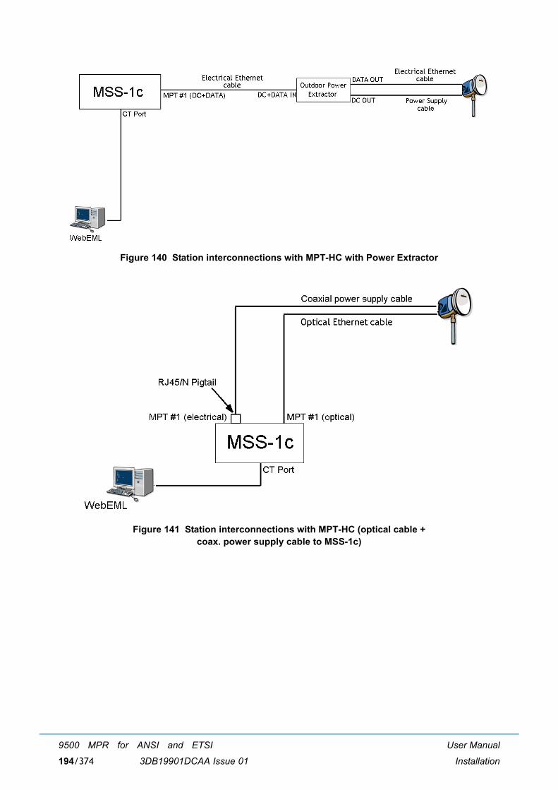
User Manual
Installation
9500 MPR for ANSI and ETSI
3DB19901DCAA Issue 01194/374
Figure 140 Station interconnections with MPT-HC with Power Extractor
Figure 141 Station interconnections with MPT-HC (optical cable + coax. power supply cable to MSS-1c)
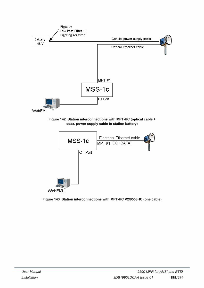
User Manual
Installation
9500 MPR for ANSI and ETSI
3DB19901DCAA Issue 01 195/374
Figure 142 Station interconnections with MPT-HC (optical cable + coax. power supply cable to station battery)
Figure 143 Station interconnections with MPT-HC V2/9558HC (one cable)
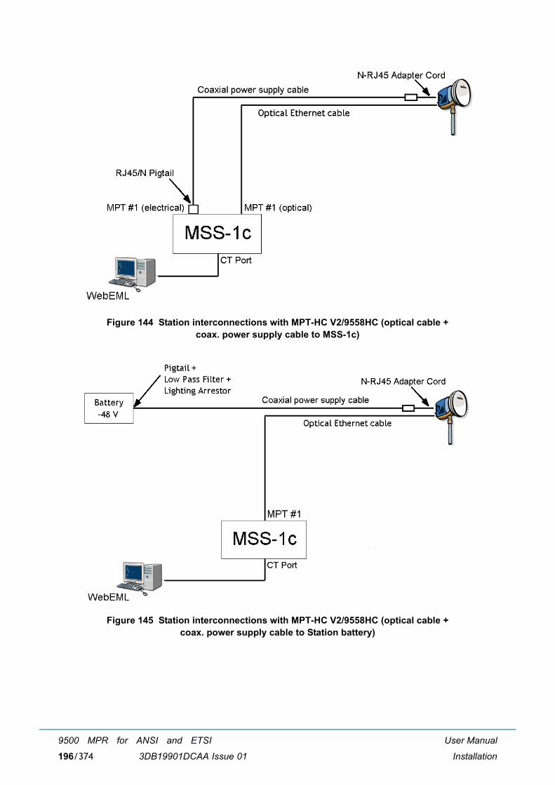
User Manual
Installation
9500 MPR for ANSI and ETSI
3DB19901DCAA Issue 01196/374
Figure 144 Station interconnections with MPT-HC V2/9558HC (optical cable + coax. power supply cable to MSS-1c)
Figure 145 Station interconnections with MPT-HC V2/9558HC (optical cable + coax. power supply cable to Station battery)
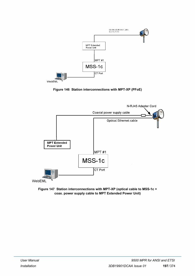
User Manual
Installation
9500 MPR for ANSI and ETSI
3DB19901DCAA Issue 01 197/374
Figure 146 Station interconnections with MPT-XP (PFoE)
Figure 147 Station interconnections with MPT-XP (optical cable to MSS-1c + coax. power supply cable to MPT Extended Power Unit)
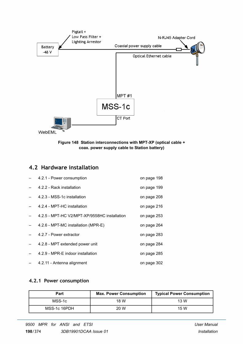
User Manual
Installation
9500 MPR for ANSI and ETSI
3DB19901DCAA Issue 01198/374
Figure 148 Station interconnections with MPT-XP (optical cable + coax. power supply cable to Station battery)
4.2 Hardware installation
� 4.2.1 - Power consumption on page 198
� 4.2.2 - Rack installation on page 199
� 4.2.3 - MSS-1c installation on page 208
� 4.2.4 - MPT-HC installation on page 216
� 4.2.5 - MPT-HC V2/MPT-XP/9558HC installation on page 253
� 4.2.6 - MPT-MC installation (MPR-E) on page 264
� 4.2.7 - Power extractor on page 283
� 4.2.8 - MPT extended power unit on page 284
� 4.2.9 - MPR-E indoor installation on page 285
� 4.2.11 - Antenna alignment on page 302
4.2.1 Power consumption
Part Max. Power Consumption Typical Power Consumption
MSS-1c 18 W 13 W
MSS-1c 16PDH 20 W 15 W
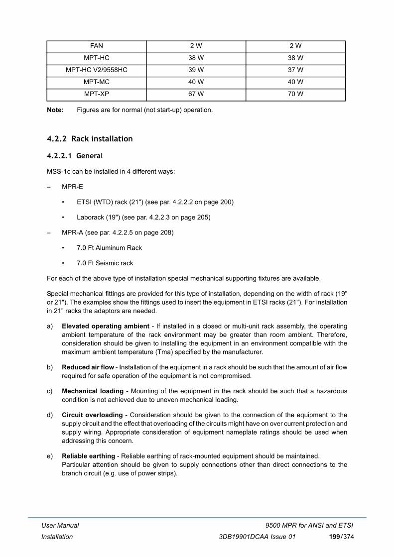
User Manual
Installation
9500 MPR for ANSI and ETSI
3DB19901DCAA Issue 01 199/374
Note: Figures are for normal (not start-up) operation.
4.2.2 Rack installation
4.2.2.1 General
MSS-1c can be installed in 4 different ways:
� MPR-E
� ETSI (WTD) rack (21") (see par. 4.2.2.2 on page 200)
� Laborack (19") (see par. 4.2.2.3 on page 205)
� MPR-A (see par. 4.2.2.5 on page 208)
� 7.0 Ft Aluminum Rack
� 7.0 Ft Seismic rack
For each of the above type of installation special mechanical supporting fixtures are available.
Special mechanical fittings are provided for this type of installation, depending on the width of rack (19"or 21"). The examples show the fittings used to insert the equipment in ETSI racks (21"). For installationin 21" racks the adaptors are needed.
a) Elevated operating ambient - If installed in a closed or multi-unit rack assembly, the operatingambient temperature of the rack environment may be greater than room ambient. Therefore,consideration should be given to installing the equipment in an environment compatible with themaximum ambient temperature (Tma) specified by the manufacturer.
b) Reduced air flow - Installation of the equipment in a rack should be such that the amount of air flowrequired for safe operation of the equipment is not compromised.
c) Mechanical loading - Mounting of the equipment in the rack should be such that a hazardouscondition is not achieved due to uneven mechanical loading.
d) Circuit overloading - Consideration should be given to the connection of the equipment to thesupply circuit and the effect that overloading of the circuits might have on over current protection andsupply wiring. Appropriate consideration of equipment nameplate ratings should be used whenaddressing this concern.
e) Reliable earthing - Reliable earthing of rack-mounted equipment should be maintained. Particular attention should be given to supply connections other than direct connections to thebranch circuit (e.g. use of power strips).
FAN 2 W 2 W
MPT-HC 38 W 38 W
MPT-HC V2/9558HC 39 W 37 W
MPT-MC 40 W 40 W
MPT-XP 67 W 70 W

User Manual
Installation
9500 MPR for ANSI and ETSI
3DB19901DCAA Issue 01200/374
4.2.2.2 ETSI rack installation (MPR-E)
4.2.2.2.1 Mechanical installation
Installation has been sub-divided into the following phases:
� Rack Positioning and Fastening
� Fixing the rack to floor using expansion bolts or Fixing to floating floor;
� T.R.U. fastening to ETSI rack.
4.2.2.2.2 Rack positioning and fastening
Proceed as follows:
� Refer to the plant documentation to see rack row assignment
� Fasten the rack to the station structure according to one of the following procedures
� Fixing the rack to floor
� Fixing the rack to floating floor
4.2.2.2.3 Fixing the rack to floor using expansion bolts
(Refer to Figure 149 and Figure 150).
� Mount the rack in a vertical position in the desired place.
� Mark the base-plate with six holes (1) to be drilled on the floor.
� Temporarily remove the rack and drill the holes at the points drawn on the floor. Place the inserts intothe holes.
� Secure the expander bolts to the floor through the base-plate holes.
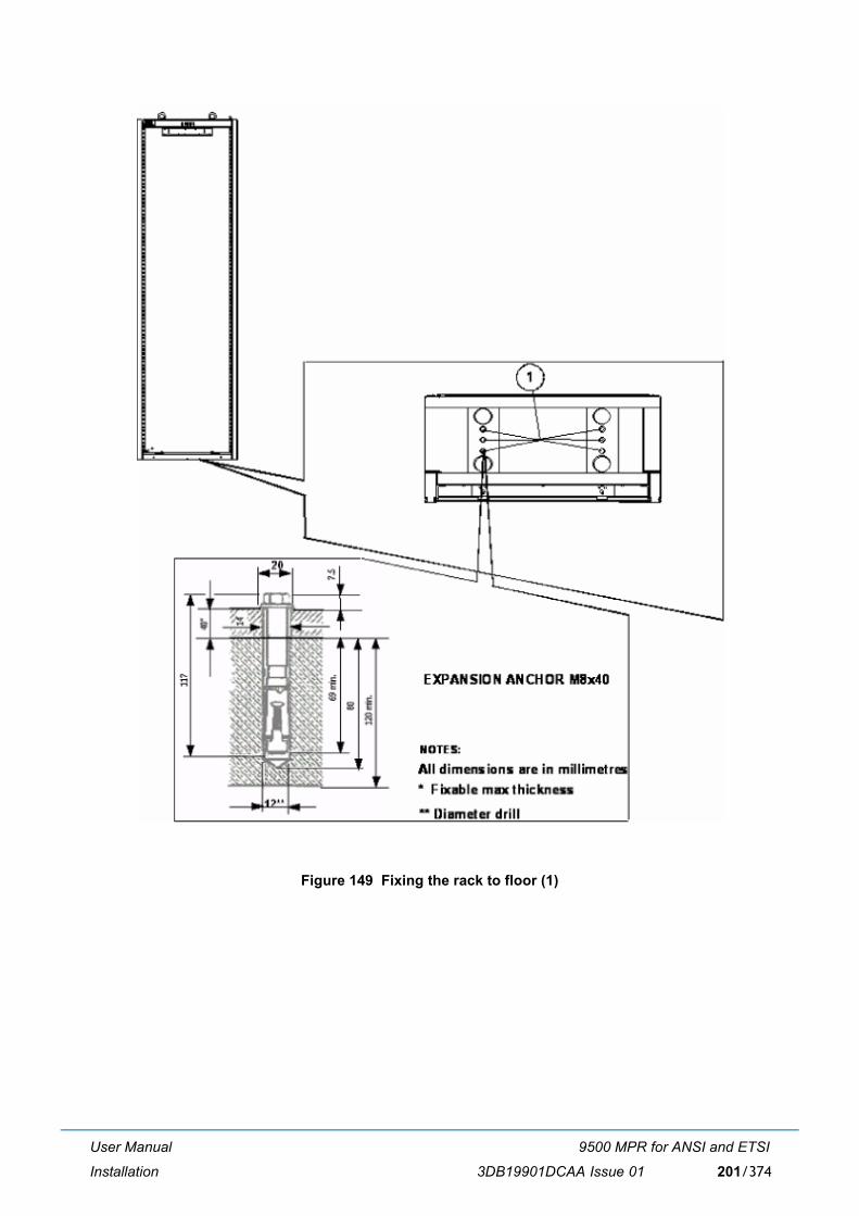
User Manual
Installation
9500 MPR for ANSI and ETSI
3DB19901DCAA Issue 01 201/374
Figure 149 Fixing the rack to floor (1)
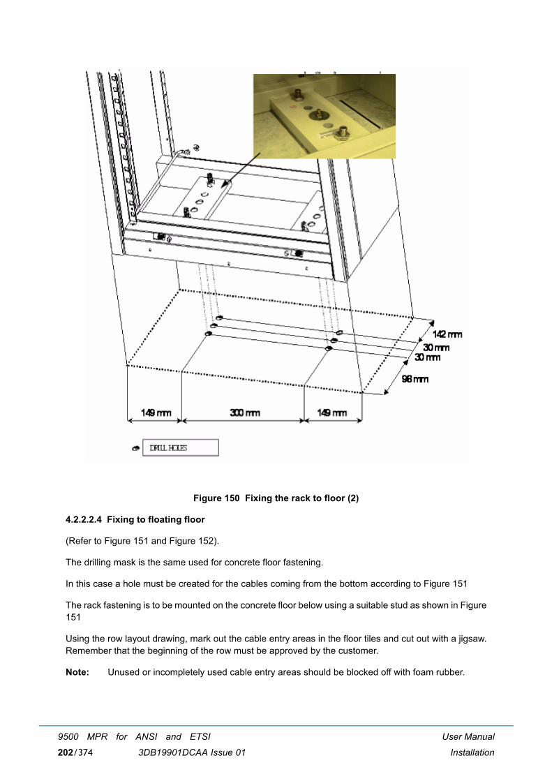
User Manual
Installation
9500 MPR for ANSI and ETSI
3DB19901DCAA Issue 01202/374
Figure 150 Fixing the rack to floor (2)
4.2.2.2.4 Fixing to floating floor
(Refer to Figure 151 and Figure 152).
The drilling mask is the same used for concrete floor fastening.
In this case a hole must be created for the cables coming from the bottom according to Figure 151
The rack fastening is to be mounted on the concrete floor below using a suitable stud as shown in Figure151
Using the row layout drawing, mark out the cable entry areas in the floor tiles and cut out with a jigsaw.Remember that the beginning of the row must be approved by the customer.
Note: Unused or incompletely used cable entry areas should be blocked off with foam rubber.
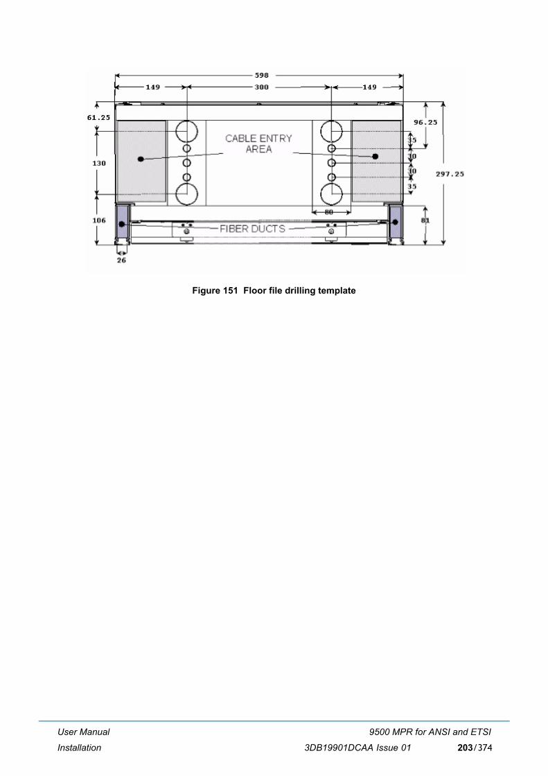
User Manual
Installation
9500 MPR for ANSI and ETSI
3DB19901DCAA Issue 01 203/374
Figure 151 Floor file drilling template
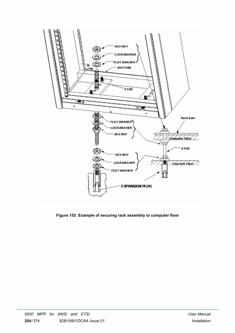
User Manual
Installation
9500 MPR for ANSI and ETSI
3DB19901DCAA Issue 01204/374
Figure 152 Example of securing rack assembly to computer floor
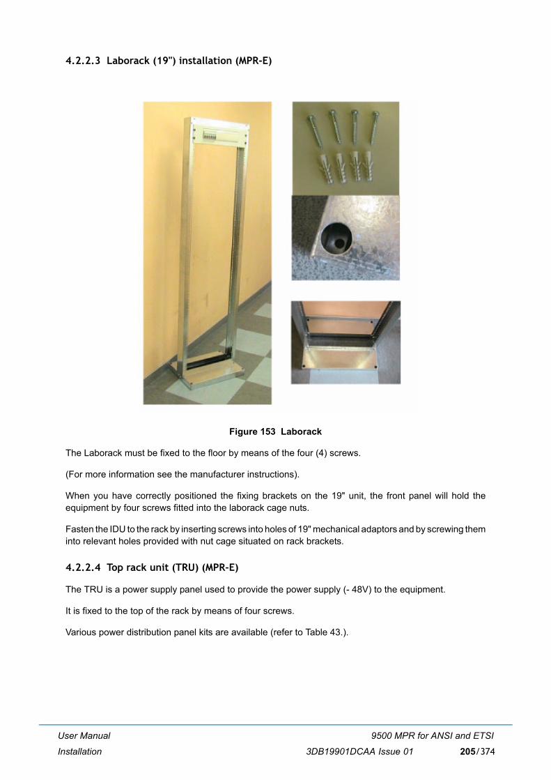
User Manual
Installation
9500 MPR for ANSI and ETSI
3DB19901DCAA Issue 01 205/374
4.2.2.3 Laborack (19") installation (MPR-E)
Figure 153 Laborack
The Laborack must be fixed to the floor by means of the four (4) screws.
(For more information see the manufacturer instructions).
When you have correctly positioned the fixing brackets on the 19" unit, the front panel will hold theequipment by four screws fitted into the laborack cage nuts.
Fasten the IDU to the rack by inserting screws into holes of 19" mechanical adaptors and by screwing theminto relevant holes provided with nut cage situated on rack brackets.
4.2.2.4 Top rack unit (TRU) (MPR-E)
The TRU is a power supply panel used to provide the power supply (- 48V) to the equipment.
It is fixed to the top of the rack by means of four screws.
Various power distribution panel kits are available (refer to Table 43.).
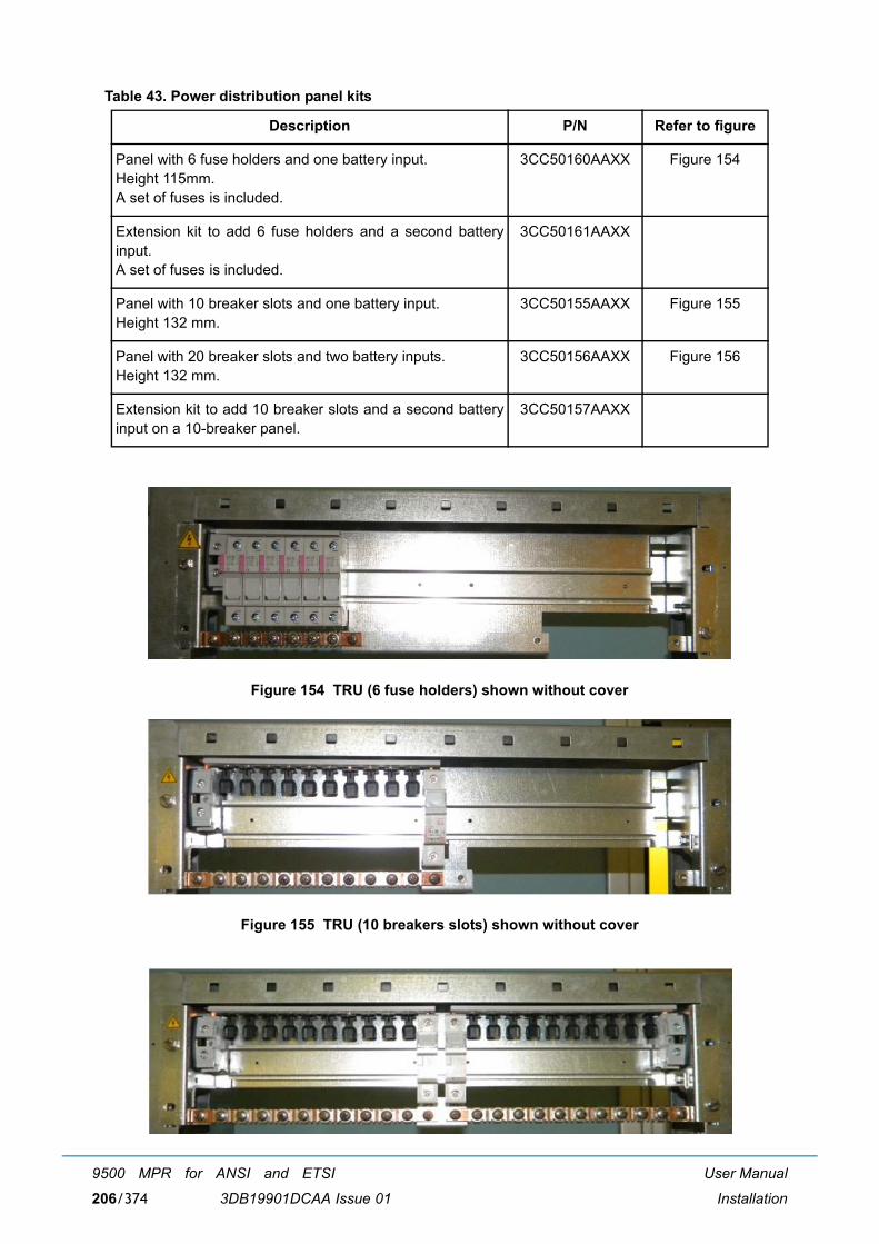
User Manual
Installation
9500 MPR for ANSI and ETSI
3DB19901DCAA Issue 01206/374
Table 43. Power distribution panel kits
Figure 154 TRU (6 fuse holders) shown without cover
Figure 155 TRU (10 breakers slots) shown without cover
Description P/N Refer to figure
Panel with 6 fuse holders and one battery input. Height 115mm.A set of fuses is included.
3CC50160AAXX Figure 154
Extension kit to add 6 fuse holders and a second batteryinput.A set of fuses is included.
3CC50161AAXX
Panel with 10 breaker slots and one battery input. Height 132 mm.
3CC50155AAXX Figure 155
Panel with 20 breaker slots and two battery inputs. Height 132 mm.
3CC50156AAXX Figure 156
Extension kit to add 10 breaker slots and a second batteryinput on a 10-breaker panel.
3CC50157AAXX
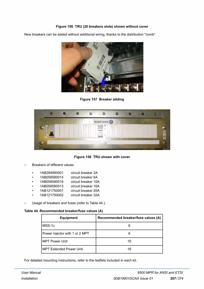
User Manual
Installation
9500 MPR for ANSI and ETSI
3DB19901DCAA Issue 01 207/374
Figure 156 TRU (20 breakers slots) shown without cover
New breakers can be added without additional wiring, thanks to the distribution "comb".
Figure 157 Breaker adding
Figure 158 TRU shown with cover
� Breakers of different values
� 1AB284990001 circuit breaker 2A� 1AB058580014 circuit breaker 6A� 1AB058580016 circuit breaker 10A� 1AB058580013 circuit breaker 16A� 1AB121750001 circuit breaker 20A� 1AB121750002 circuit breaker 32A
� Usage of breakers and fuses (refer to Table 44.).
Table 44. Recommended breaker/fuse values (A)
For detailed mounting instructions, refer to the leaflets included in each kit.
Equipment Recommended breaker/fuse values (A)
MSS-1c 6
Power injector with 1 or 2 MPT 6
MPT Power Unit 10
MPT Extended Power Unit 16
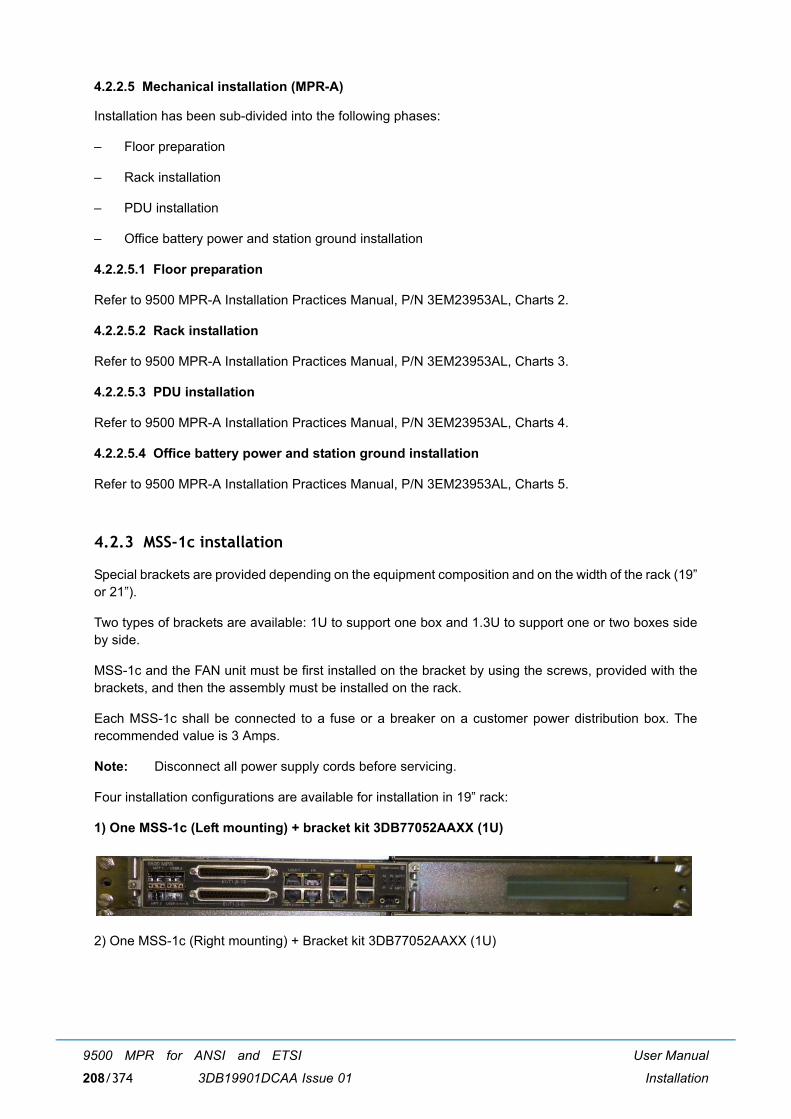
User Manual
Installation
9500 MPR for ANSI and ETSI
3DB19901DCAA Issue 01208/374
4.2.2.5 Mechanical installation (MPR-A)
Installation has been sub-divided into the following phases:
� Floor preparation
� Rack installation
� PDU installation
� Office battery power and station ground installation
4.2.2.5.1 Floor preparation
Refer to 9500 MPR-A Installation Practices Manual, P/N 3EM23953AL, Charts 2.
4.2.2.5.2 Rack installation
Refer to 9500 MPR-A Installation Practices Manual, P/N 3EM23953AL, Charts 3.
4.2.2.5.3 PDU installation
Refer to 9500 MPR-A Installation Practices Manual, P/N 3EM23953AL, Charts 4.
4.2.2.5.4 Office battery power and station ground installation
Refer to 9500 MPR-A Installation Practices Manual, P/N 3EM23953AL, Charts 5.
4.2.3 MSS-1c installation
Special brackets are provided depending on the equipment composition and on the width of the rack (19�or 21�).
Two types of brackets are available: 1U to support one box and 1.3U to support one or two boxes sideby side.
MSS-1c and the FAN unit must be first installed on the bracket by using the screws, provided with thebrackets, and then the assembly must be installed on the rack.
Each MSS-1c shall be connected to a fuse or a breaker on a customer power distribution box. Therecommended value is 3 Amps.
Note: Disconnect all power supply cords before servicing.
Four installation configurations are available for installation in 19� rack:
1) One MSS-1c (Left mounting) + bracket kit 3DB77052AAXX (1U)
2) One MSS-1c (Right mounting) + Bracket kit 3DB77052AAXX (1U)
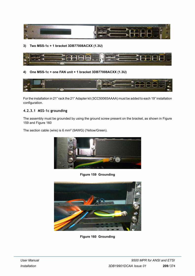
User Manual
Installation
9500 MPR for ANSI and ETSI
3DB19901DCAA Issue 01 209/374
3) Two MSS-1c + 1 bracket 3DB77008ACXX (1.3U)
4) One MSS-1c + one FAN unit + 1 bracket 3DB77008ACXX (1.3U)
For the installation in 21� rack the 21� Adapter kit (3CC50065AAAA) must be added to each 19� installationconfiguration.
4.2.3.1 MSS-1c grounding
The assembly must be grounded by using the ground screw present on the bracket, as shown in Figure159 and Figure 160
The section cable (wire) is 6 mm² (9AWG) (Yellow/Green).
Figure 159 Grounding
Figure 160 Grounding
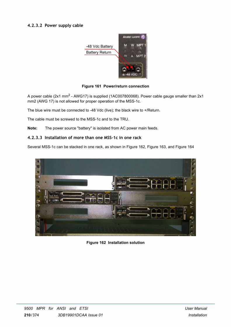
User Manual
Installation
9500 MPR for ANSI and ETSI
3DB19901DCAA Issue 01210/374
4.2.3.2 Power supply cable
Figure 161 Power/return connection
A power cable (2x1 mm2 - AWG17) is supplied (1AC007800068). Power cable gauge smaller than 2x1mm2 (AWG 17) is not allowed for proper operation of the MSS-1c.
The blue wire must be connected to -48 Vdc (live); the black wire to +/Return.
The cable must be screwed to the MSS-1c and to the TRU.
Note: The power source "battery" is isolated from AC power main feeds.
4.2.3.3 Installation of more than one MSS-1c in one rack
Several MSS-1c can be stacked in one rack, as shown in Figure 162, Figure 163, and Figure 164
Figure 162 Installation solution
Battery Return-48 Vdc Battery
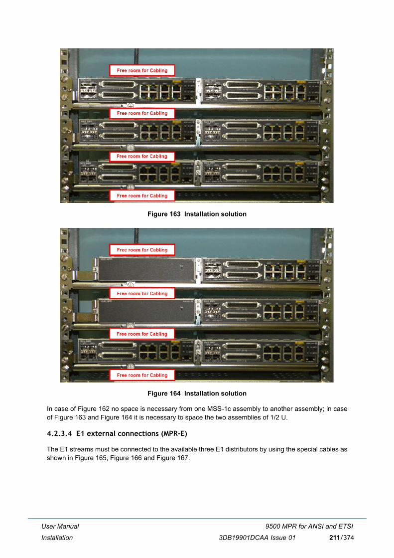
User Manual
Installation
9500 MPR for ANSI and ETSI
3DB19901DCAA Issue 01 211/374
Figure 163 Installation solution
Figure 164 Installation solution
In case of Figure 162 no space is necessary from one MSS-1c assembly to another assembly; in caseof Figure 163 and Figure 164 it is necessary to space the two assemblies of 1/2 U.
4.2.3.4 E1 external connections (MPR-E)
The E1 streams must be connected to the available three E1 distributors by using the special cables asshown in Figure 165, Figure 166 and Figure 167.
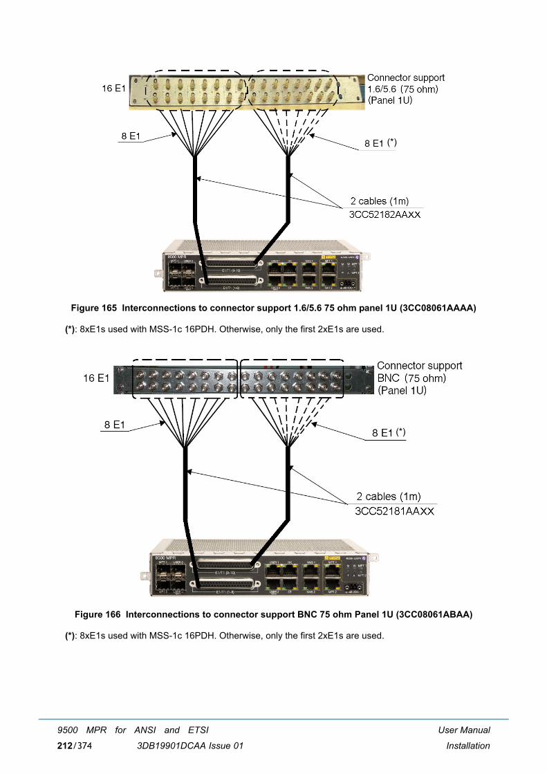
User Manual
Installation
9500 MPR for ANSI and ETSI
3DB19901DCAA Issue 01212/374
Figure 165 Interconnections to connector support 1.6/5.6 75 ohm panel 1U (3CC08061AAAA)
(*): 8xE1s used with MSS-1c 16PDH. Otherwise, only the first 2xE1s are used.
Figure 166 Interconnections to connector support BNC 75 ohm Panel 1U (3CC08061ABAA)
(*): 8xE1s used with MSS-1c 16PDH. Otherwise, only the first 2xE1s are used.
(*)
(*)
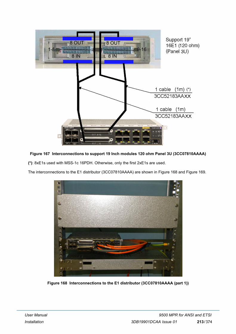
User Manual
Installation
9500 MPR for ANSI and ETSI
3DB19901DCAA Issue 01 213/374
Figure 167 Interconnections to support 19 Inch modules 120 ohm Panel 3U (3CC07810AAAA)
(*): 8xE1s used with MSS-1c 16PDH. Otherwise, only the first 2xE1s are used.
The interconnections to the E1 distributor (3CC07810AAAA) are shown in Figure 168 and Figure 169.
Figure 168 Interconnections to the E1 distributor (3CC07810AAAA (part 1))
9-161-88 OUT
8 IN
8 OUT
8 IN
(*)
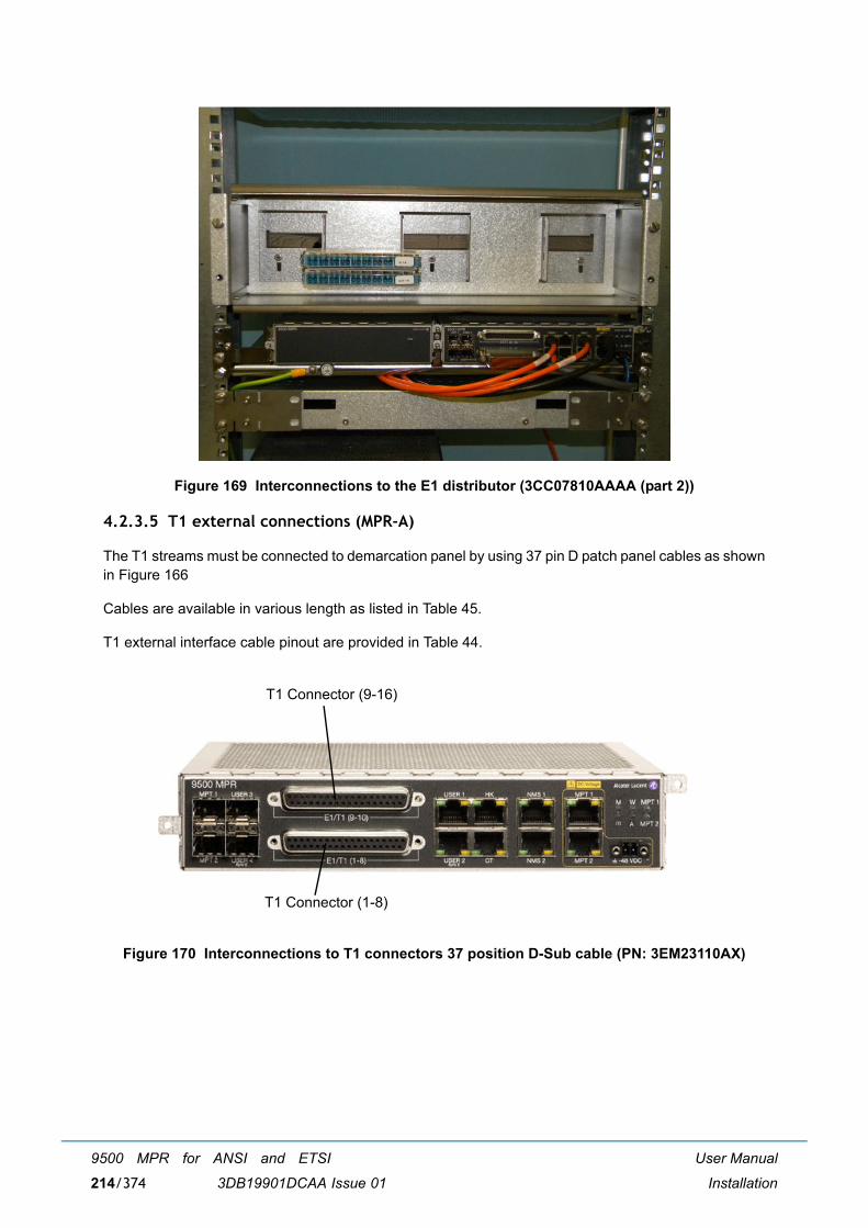
User Manual
Installation
9500 MPR for ANSI and ETSI
3DB19901DCAA Issue 01214/374
Figure 169 Interconnections to the E1 distributor (3CC07810AAAA (part 2))
4.2.3.5 T1 external connections (MPR-A)
The T1 streams must be connected to demarcation panel by using 37 pin D patch panel cables as shownin Figure 166
Cables are available in various length as listed in Table 45.
T1 external interface cable pinout are provided in Table 44.
Figure 170 Interconnections to T1 connectors 37 position D-Sub cable (PN: 3EM23110AX)
T1 Connector (9-16)
T1 Connector (1-8)
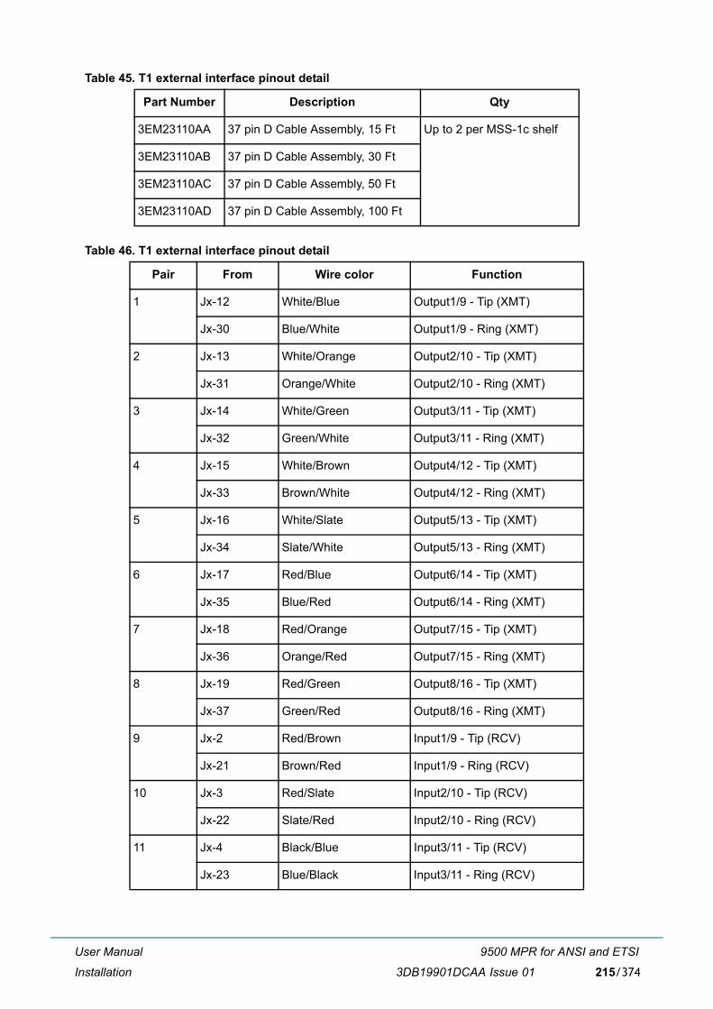
User Manual
Installation
9500 MPR for ANSI and ETSI
3DB19901DCAA Issue 01 215/374
Table 45. T1 external interface pinout detail
Table 46. T1 external interface pinout detail
Part Number Description Qty
3EM23110AA 37 pin D Cable Assembly, 15 Ft Up to 2 per MSS-1c shelf
3EM23110AB 37 pin D Cable Assembly, 30 Ft
3EM23110AC 37 pin D Cable Assembly, 50 Ft
3EM23110AD 37 pin D Cable Assembly, 100 Ft
Pair From Wire color Function
1 Jx-12 White/Blue Output1/9 - Tip (XMT)
Jx-30 Blue/White Output1/9 - Ring (XMT)
2 Jx-13 White/Orange Output2/10 - Tip (XMT)
Jx-31 Orange/White Output2/10 - Ring (XMT)
3 Jx-14 White/Green Output3/11 - Tip (XMT)
Jx-32 Green/White Output3/11 - Ring (XMT)
4 Jx-15 White/Brown Output4/12 - Tip (XMT)
Jx-33 Brown/White Output4/12 - Ring (XMT)
5 Jx-16 White/Slate Output5/13 - Tip (XMT)
Jx-34 Slate/White Output5/13 - Ring (XMT)
6 Jx-17 Red/Blue Output6/14 - Tip (XMT)
Jx-35 Blue/Red Output6/14 - Ring (XMT)
7 Jx-18 Red/Orange Output7/15 - Tip (XMT)
Jx-36 Orange/Red Output7/15 - Ring (XMT)
8 Jx-19 Red/Green Output8/16 - Tip (XMT)
Jx-37 Green/Red Output8/16 - Ring (XMT)
9 Jx-2 Red/Brown Input1/9 - Tip (RCV)
Jx-21 Brown/Red Input1/9 - Ring (RCV)
10 Jx-3 Red/Slate Input2/10 - Tip (RCV)
Jx-22 Slate/Red Input2/10 - Ring (RCV)
11 Jx-4 Black/Blue Input3/11 - Tip (RCV)
Jx-23 Blue/Black Input3/11 - Ring (RCV)
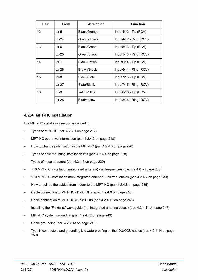
User Manual
Installation
9500 MPR for ANSI and ETSI
3DB19901DCAA Issue 01216/374
4.2.4 MPT-HC installation
The MPT-HC installation section is divided in:
� Types of MPT-HC (par. 4.2.4.1 on page 217)
� MPT-HC operative information (par. 4.2.4.2 on page 218)
� How to change polarization in the MPT-HC (par. 4.2.4.3 on page 226)
� Types of pole mounting installation kits (par. 4.2.4.4 on page 228)
� Types of nose adapters (par. 4.2.4.5 on page 229)
� 1+0 MPT-HC installation (integrated antenna) - all frequencies (par. 4.2.4.6 on page 230)
� 1+0 MPT-HC installation (non integrated antenna) - all frequencies (par. 4.2.4.7 on page 233)
� How to pull up the cables from indoor to the MPT-HC (par. 4.2.4.8 on page 235)
� Cable connection to MPT-HC (11-38 GHz) (par. 4.2.4.9 on page 240)
� Cable connection to MPT-HC (6-7-8 GHz) (par. 4.2.4.10 on page 245)
� Installing the �Flextwist� waveguide (not integrated antenna cases) (par. 4.2.4.11 on page 247)
� MPT-HC system grounding (par. 4.2.4.12 on page 249)
� Cable grounding (par. 4.2.4.13 on page 249)
� Type N connectors and grounding kits waterproofing on the IDU/ODU cables (par. 4.2.4.14 on page250)
12 Jx-5 Black/Orange Input4/12 - Tip (RCV)
Jx-24 Orange/Black Input4/12 - Ring (RCV)
13 Jx-6 Black/Green Input5/13 - Tip (RCV)
Jx-25 Green/Black Input5/13 - Ring (RCV)
14 Jx-7 Black/Brown Input6/14 - Tip (RCV)
Jx-26 Brown/Black Input6/14 - Ring (RCV)
15 Jx-8 Black/Slate Input7/15 - Tip (RCV)
Jx-27 Slate/Black Input7/15 - Ring (RCV)
16 Jx-9 Yellow/Blue Input8/16 - Tip (RCV)
Jx-28 Blue/Yellow Input8/16 - Ring (RCV)
Pair From Wire color Function

User Manual
Installation
9500 MPR for ANSI and ETSI
3DB19901DCAA Issue 01 217/374
4.2.4.1 Types of MPT-HC
The MPT-HC consists of one or two cabinets including the Ethernet interface + modem + RF transceiver+ branching of a channel.
Three mechanical solutions are adopted:
[1] with embedded diplexer for cost optimisation (11 GHz to 38 GHz), shown in Figure 171, where thebranching (diplexer) is internal to the MPT-HC cabinet; this type of MPT-HC is identified by oneLogistical Item only;
[2] with embedded diplexer for cost optimisation and different mechanics from 11-38 GHz (6 GHz),shown in Figure 172, where the branching (diplexer) is internal to the MPT-HC cabinet; this type ofMPT-HC is identified by one Logistical Item only;
[3] with external diplexer: due to an high number of shifters the diplexer is external for the flexibility ofthe shifter customization, shown in Figure 173, where MPT-HC is composed by two independentunits: the BRANCHING assembly (containing the diplexer) and the RF TRANSCEIVER assembly(containing the RF section); each of this type of MPT-HC is identified by two Logistical Items, onefor the BRANCHING assembly and another for the RF TRANSCEIVER assembly. To read theBRANCHING assembly identification label it is necessary to separate the BRANCHING assemblyfrom the RF TRANSCEIVER assembly.
Figure 171 Views of MPT-HC with embedded diplexer (11-38 GHz)
TRANSCEIVER + BRANCHING MPT-HC IDENTIFICATION LABEL
CO-BOX
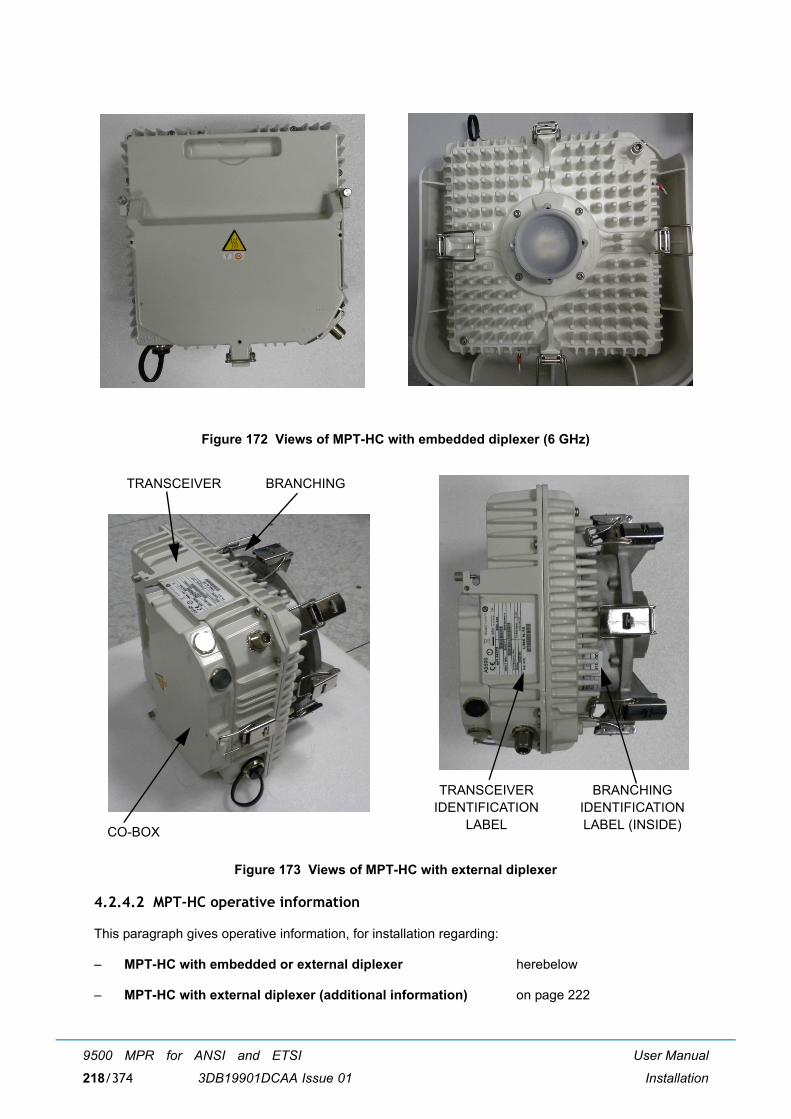
User Manual
Installation
9500 MPR for ANSI and ETSI
3DB19901DCAA Issue 01218/374
Figure 172 Views of MPT-HC with embedded diplexer (6 GHz)
Figure 173 Views of MPT-HC with external diplexer
4.2.4.2 MPT-HC operative information
This paragraph gives operative information, for installation regarding:
� MPT-HC with embedded or external diplexer herebelow
� MPT-HC with external diplexer (additional information) on page 222
TRANSCEIVER
CO-BOX
BRANCHING
BRANCHINGIDENTIFICATION LABEL (INSIDE)
TRANSCEIVERIDENTIFICATION
LABEL
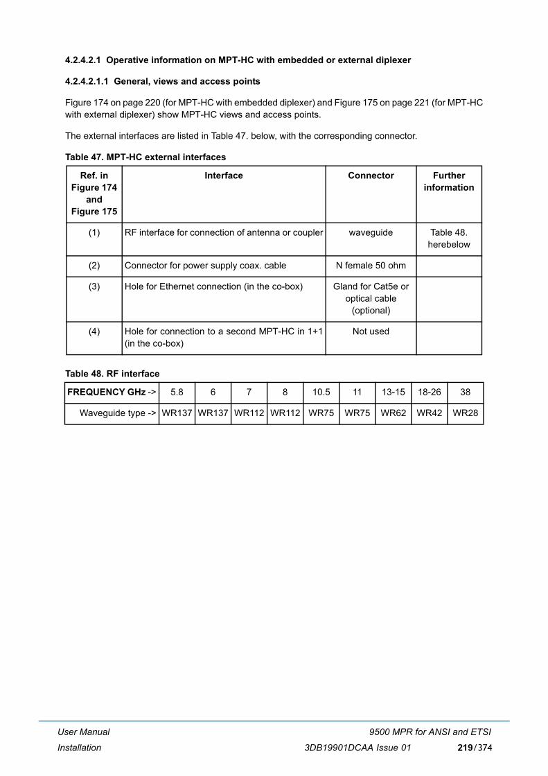
User Manual
Installation
9500 MPR for ANSI and ETSI
3DB19901DCAA Issue 01 219/374
4.2.4.2.1 Operative information on MPT-HC with embedded or external diplexer
4.2.4.2.1.1 General, views and access points
Figure 174 on page 220 (for MPT-HC with embedded diplexer) and Figure 175 on page 221 (for MPT-HCwith external diplexer) show MPT-HC views and access points.
The external interfaces are listed in Table 47. below, with the corresponding connector.
Table 47. MPT-HC external interfaces
Table 48. RF interface
Ref. in Figure 174
and Figure 175
Interface Connector Further information
(1) RF interface for connection of antenna or coupler waveguide Table 48. herebelow
(2) Connector for power supply coax. cable N female 50 ohm
(3) Hole for Ethernet connection (in the co-box) Gland for Cat5e or optical cable
(optional)
(4) Hole for connection to a second MPT-HC in 1+1(in the co-box)
Not used
FREQUENCY GHz -> 5.8 6 7 8 10.5 11 13-15 18-26 38
Waveguide type -> WR137 WR137 WR112 WR112 WR75 WR75 WR62 WR42 WR28
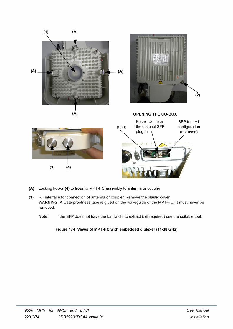
User Manual
Installation
9500 MPR for ANSI and ETSI
3DB19901DCAA Issue 01220/374
Figure 174 Views of MPT-HC with embedded diplexer (11-38 GHz)
(A) Locking hooks (4) to fix/unfix MPT-HC assembly to antenna or coupler
(1) RF interface for connection of antenna or coupler. Remove the plastic cover.WARNING: A waterproofness tape is glued on the waveguide of the MPT-HC. It must never beremoved.
Note: If the SFP does not have the bail latch, to extract it (if required) use the suitable tool.
(1) (A)
(A)(A)
(A)
(2)
(3) (4)
RJ45SFP for 1+1 configuration
(not used)
Place to installthe optional SFPplug-in
OPENING THE CO-BOX
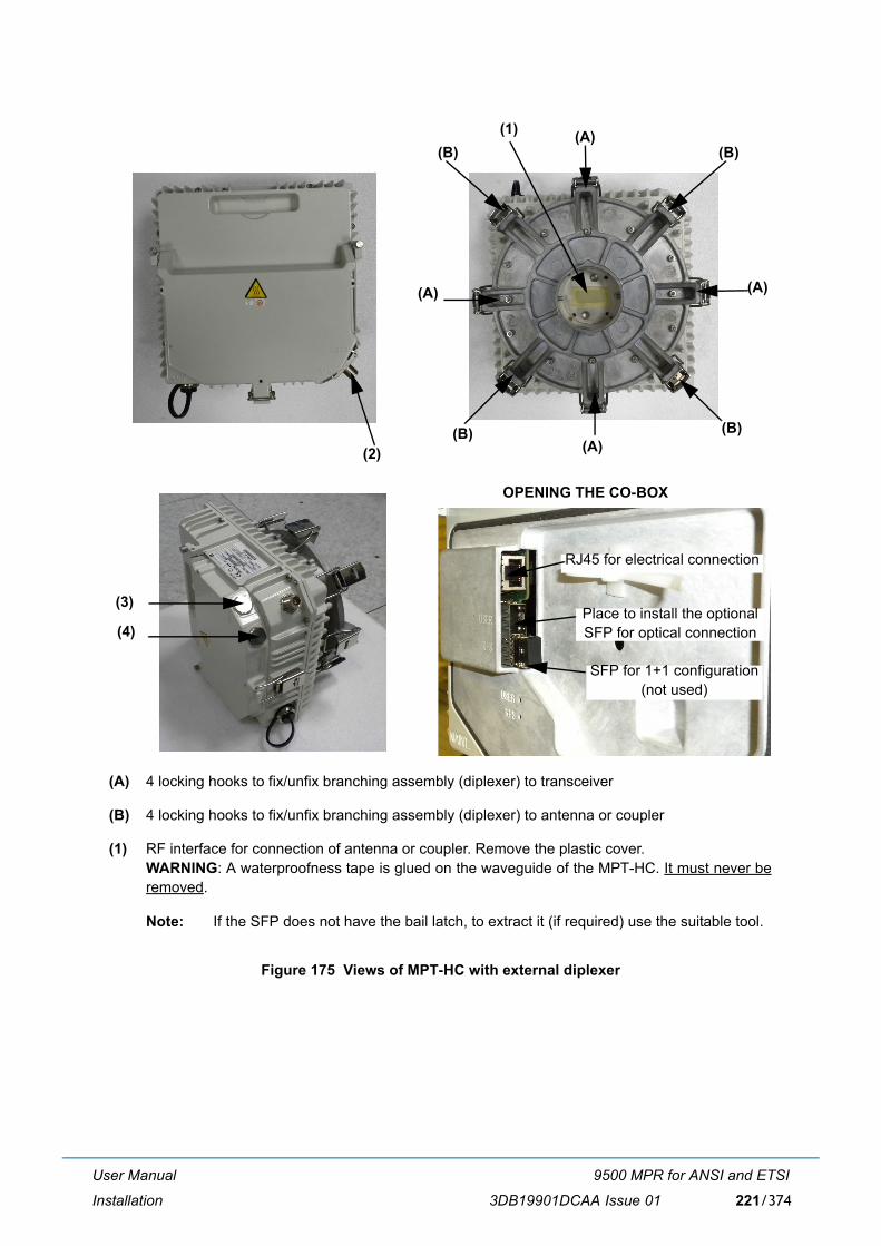
User Manual
Installation
9500 MPR for ANSI and ETSI
3DB19901DCAA Issue 01 221/374
Figure 175 Views of MPT-HC with external diplexer
(A) 4 locking hooks to fix/unfix branching assembly (diplexer) to transceiver
(B) 4 locking hooks to fix/unfix branching assembly (diplexer) to antenna or coupler
(1) RF interface for connection of antenna or coupler. Remove the plastic cover.WARNING: A waterproofness tape is glued on the waveguide of the MPT-HC. It must never beremoved.
Note: If the SFP does not have the bail latch, to extract it (if required) use the suitable tool.
(1) (A)
(A)(A)
(A)(2)
(B)(B)
(B)(B)
(3)
(4)
SFP for 1+1 configuration(not used)
Place to install the optional SFP for optical connection
OPENING THE CO-BOX
RJ45 for electrical connection
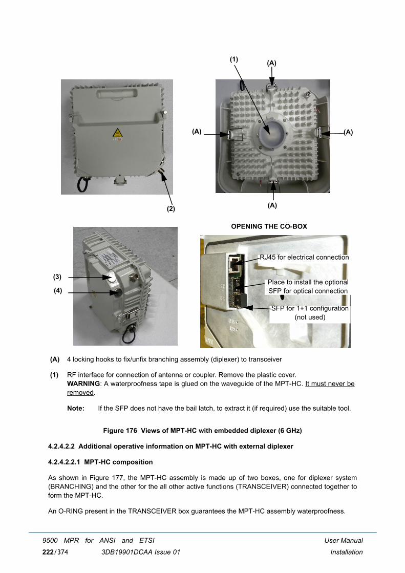
User Manual
Installation
9500 MPR for ANSI and ETSI
3DB19901DCAA Issue 01222/374
Figure 176 Views of MPT-HC with embedded diplexer (6 GHz)
4.2.4.2.2 Additional operative information on MPT-HC with external diplexer
4.2.4.2.2.1 MPT-HC composition
As shown in Figure 177, the MPT-HC assembly is made up of two boxes, one for diplexer system(BRANCHING) and the other for the all other active functions (TRANSCEIVER) connected together toform the MPT-HC.
An O-RING present in the TRANSCEIVER box guarantees the MPT-HC assembly waterproofness.
(A) 4 locking hooks to fix/unfix branching assembly (diplexer) to transceiver
(1) RF interface for connection of antenna or coupler. Remove the plastic cover.WARNING: A waterproofness tape is glued on the waveguide of the MPT-HC. It must never beremoved.
Note: If the SFP does not have the bail latch, to extract it (if required) use the suitable tool.
(1) (A)
(A)(A)
(A)(2)
(3)
(4)
SFP for 1+1 configuration(not used)
Place to install the optional SFP for optical connection
OPENING THE CO-BOX
RJ45 for electrical connection

User Manual
Installation
9500 MPR for ANSI and ETSI
3DB19901DCAA Issue 01 223/374
Note: This is a conductive O-RING and must be left dry. Do not wet it with silicon grease (silicongrease must be used only on O-ring between MPT-HC and antenna).
Figure 177 Composition of MPT-HC with external diplexer
WARNING 1: A waterproofness tape is glued on the waveguide of the MPT-HC. It must never be removed.
WARNING 2: This gasket must never be removed.
The TRANSCEIVER box performs all the functions, but does not include the diplexer system.
The BRANCHING box provides the interface between the pole mounting/antenna and theTRANSCEIVER.
The favorite solution foresees the possibility to change in field a spare part TRANSCEIVER withoutdisconnecting the BRANCHING box from the pole mounting/antenna. The TRANSCEIVER andBRANCHING boxes fixing and unfixing are obtained through the four levers.
4.2.4.2.2.2 TRANSCEIVER and BRANCHING boxes coupling
Figure 178 below shows the TRANSCEIVER and BRANCHING boxes coupling surfaces:
� (A) BRANCHING box label informative contentdescribed in Figure 180 on page 226
� (B) (HIGH FREQ) and (C) (LOW FREQ) RF interfaces on BRANCHING box
� (D) (TX) and (E) (RX) RF interfaces on TRANSCEIVER box
The TRANSCEIVER and BRANCHING boxes can be coupled in two alternative ways (180°-rotated withrespect to each other):
� BRANCHING box (B) (HIGH FREQ) coupled to TRANSCEIVER box�s (D) (TX)
BRANCHING TRANSCEIVER
WARNING 1 WARNING 2
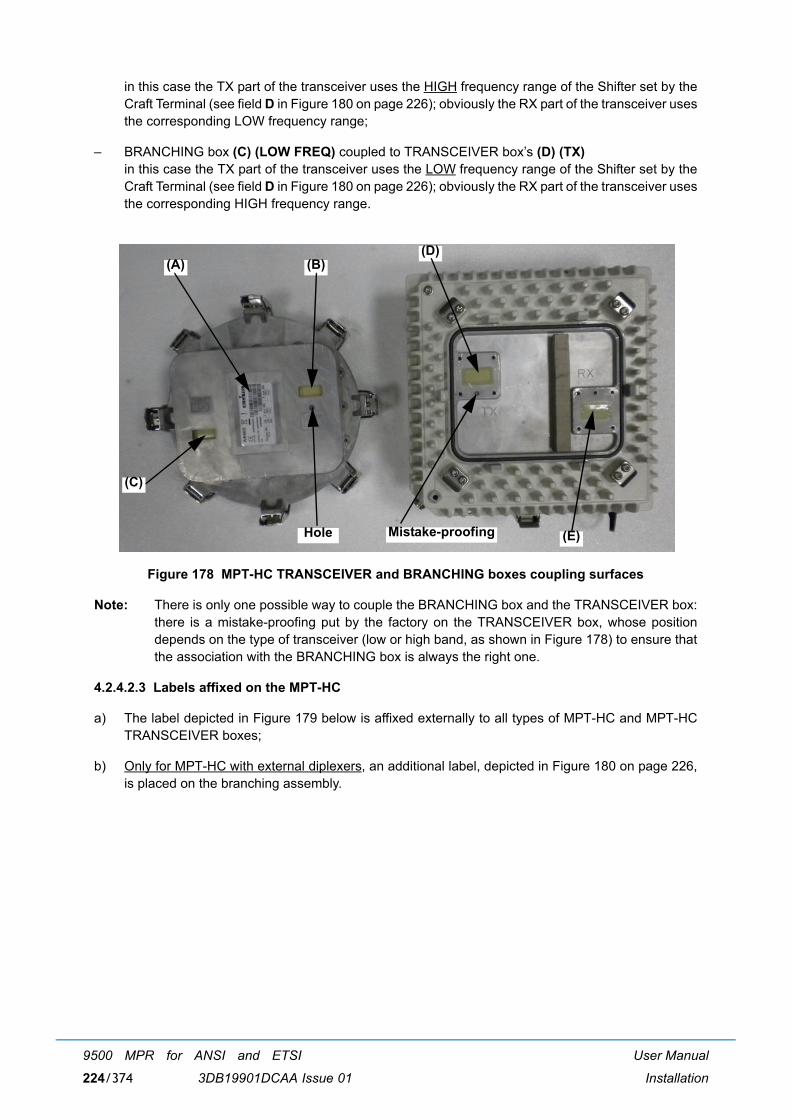
User Manual
Installation
9500 MPR for ANSI and ETSI
3DB19901DCAA Issue 01224/374
in this case the TX part of the transceiver uses the HIGH frequency range of the Shifter set by theCraft Terminal (see field D in Figure 180 on page 226); obviously the RX part of the transceiver usesthe corresponding LOW frequency range;
� BRANCHING box (C) (LOW FREQ) coupled to TRANSCEIVER box�s (D) (TX)in this case the TX part of the transceiver uses the LOW frequency range of the Shifter set by theCraft Terminal (see field D in Figure 180 on page 226); obviously the RX part of the transceiver usesthe corresponding HIGH frequency range.
Figure 178 MPT-HC TRANSCEIVER and BRANCHING boxes coupling surfaces
Note: There is only one possible way to couple the BRANCHING box and the TRANSCEIVER box:there is a mistake-proofing put by the factory on the TRANSCEIVER box, whose positiondepends on the type of transceiver (low or high band, as shown in Figure 178) to ensure thatthe association with the BRANCHING box is always the right one.
4.2.4.2.3 Labels affixed on the MPT-HC
a) The label depicted in Figure 179 below is affixed externally to all types of MPT-HC and MPT-HCTRANSCEIVER boxes;
b) Only for MPT-HC with external diplexers, an additional label, depicted in Figure 180 on page 226,is placed on the branching assembly.
(A) (B)
(C)
(D)
(E)Hole Mistake-proofing

User Manual
Installation
9500 MPR for ANSI and ETSI
3DB19901DCAA Issue 01 225/374
Figure 179 Label affixed on the MPT-HC and MPT-HC TRANSCEIVER box
SYMBOL OR WRITING MEANING
9500-MPR Equipment Acronym & Alcatel-Lucent Logo
CE European Community logo
! Not harmonized frequency logo
2002/96/EC WEEE (Waste Electrical andElectronic Equipment) Logo
-28 V / -58 V 1,6 A / 0,8 A Power supply range and current range
Logistical Item (shown numbers as examples) Logistical Item for Customer
A Logistical Item for Customer, bar code 128
Serial n° (shown numbers as examples) Factory Serial number
B Factory Serial number bar code 128
TX Frequency MHz (shown numbers as examples) Working frequency range
Shifter MHz (shown numbers as examples) Shifter
TX Sub-band (shown numbers as examples) TX Sub-band
Initial SW/ICS (shown numbers as examples) P/N and ICS of the software loaded in factory
PN/ICS (shown numbers as examples) Factory P/N + ICS
C Factory P/N + ICS bar code 128
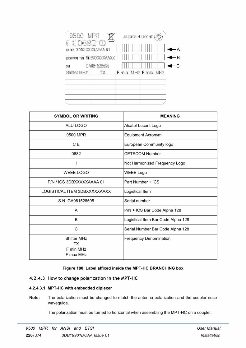
User Manual
Installation
9500 MPR for ANSI and ETSI
3DB19901DCAA Issue 01226/374
Figure 180 Label affixed inside the MPT-HC BRANCHING box
4.2.4.3 How to change polarization in the MPT-HC
4.2.4.3.1 MPT-HC with embedded diplexer
Note: The polarization must be changed to match the antenna polarization and the coupler nosewaveguide.
The polarization must be turned to horizontal when assembling the MPT-HC on a coupler.
SYMBOL OR WRITING MEANING
ALU LOGO Alcatel-Lucent Logo
9500 MPR Equipment Acronym
C E European Community logo
0682 CETECOM Number
! Not Harmonized Frequency Logo
WEEE LOGO WEEE Logo
P/N / ICS 3DBXXXXXAAAA 01 Part Number + ICS
LOGISTICAL ITEM 3DBXXXXXAAXX Logistical Item
S.N. GA081528595 Serial number
A P/N + ICS Bar Code Alpha 128
B Logistical Item Bar Code Alpha 128
C Serial Number Bar Code Alpha 128
Shifter MHzTX
F min MHzF max MHz
Frequency Denomination
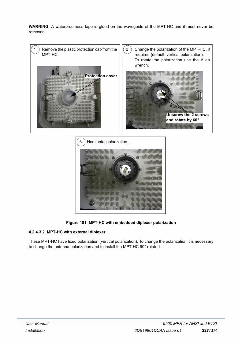
User Manual
Installation
9500 MPR for ANSI and ETSI
3DB19901DCAA Issue 01 227/374
WARNING: A waterproofness tape is glued on the waveguide of the MPT-HC and it must never beremoved.
Figure 181 MPT-HC with embedded diplexer polarization
4.2.4.3.2 MPT-HC with external diplexer
These MPT-HC have fixed polarization (vertical polarization). To change the polarization it is necessaryto change the antenna polarization and to install the MPT-HC 90° rotated.
1 2
3
Remove the plastic protection cap from theMPT-HC.
Change the polarization of the MPT-HC, ifrequired (default: vertical polarization).To rotate the polarization use the Allenwrench.
Horizontal polarization.
Protection cover
Unscrew the 2 screwsand rotate by 60°
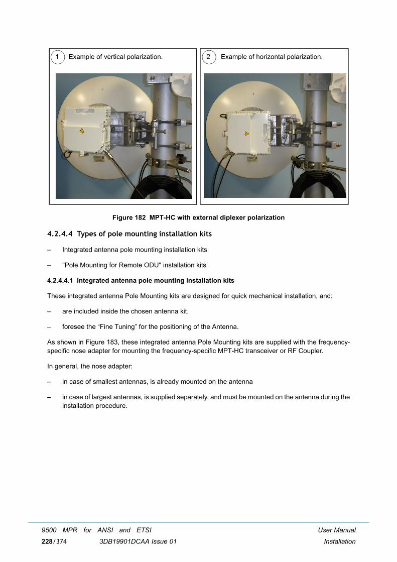
User Manual
Installation
9500 MPR for ANSI and ETSI
3DB19901DCAA Issue 01228/374
Figure 182 MPT-HC with external diplexer polarization
4.2.4.4 Types of pole mounting installation kits
� Integrated antenna pole mounting installation kits
� "Pole Mounting for Remote ODU" installation kits
4.2.4.4.1 Integrated antenna pole mounting installation kits
These integrated antenna Pole Mounting kits are designed for quick mechanical installation, and:
� are included inside the chosen antenna kit.
� foresee the �Fine Tuning� for the positioning of the Antenna.
As shown in Figure 183, these integrated antenna Pole Mounting kits are supplied with the frequency-specific nose adapter for mounting the frequency-specific MPT-HC transceiver or RF Coupler.
In general, the nose adapter:
� in case of smallest antennas, is already mounted on the antenna
� in case of largest antennas, is supplied separately, and must be mounted on the antenna during theinstallation procedure.
1 2Example of vertical polarization. Example of horizontal polarization.
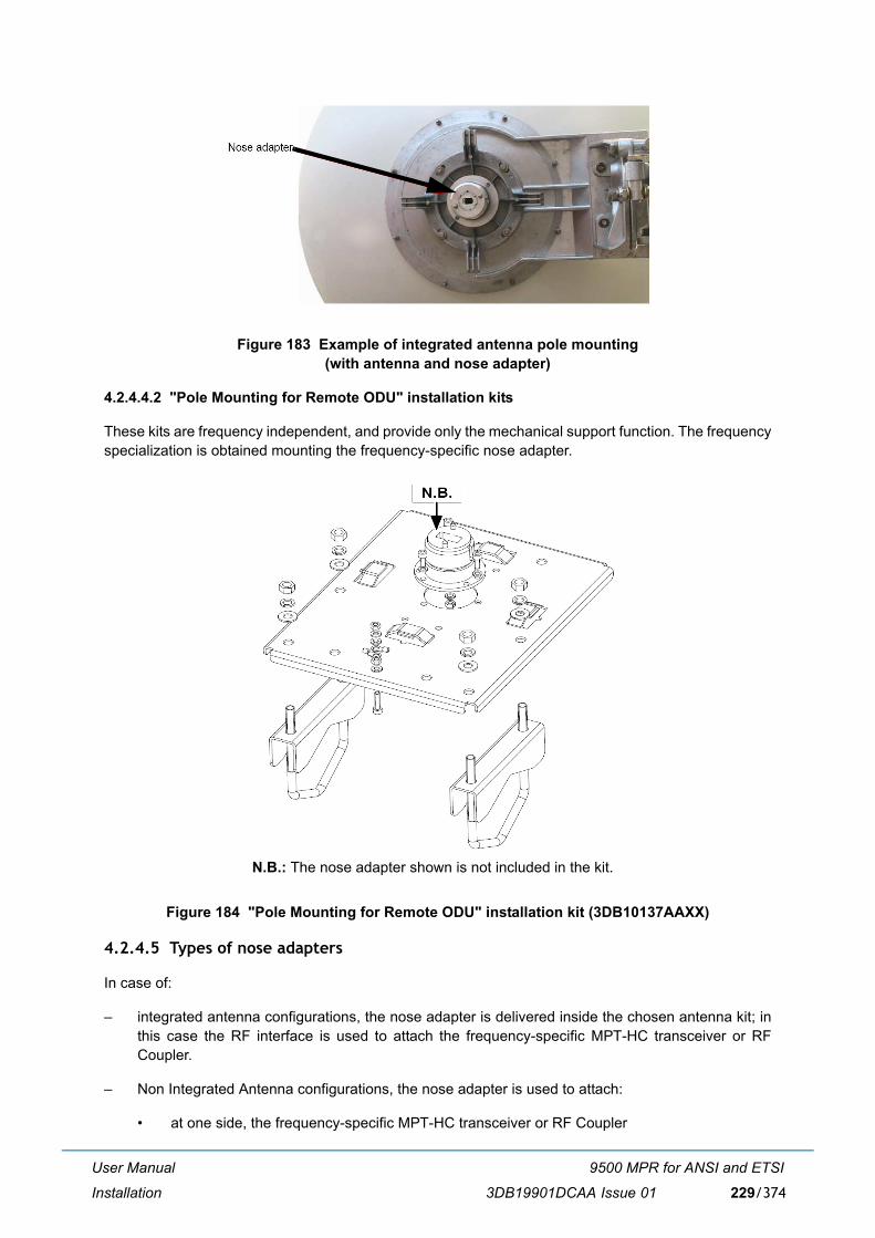
User Manual
Installation
9500 MPR for ANSI and ETSI
3DB19901DCAA Issue 01 229/374
Figure 183 Example of integrated antenna pole mounting (with antenna and nose adapter)
4.2.4.4.2 "Pole Mounting for Remote ODU" installation kits
These kits are frequency independent, and provide only the mechanical support function. The frequencyspecialization is obtained mounting the frequency-specific nose adapter.
Figure 184 "Pole Mounting for Remote ODU" installation kit (3DB10137AAXX)
4.2.4.5 Types of nose adapters
In case of:
� integrated antenna configurations, the nose adapter is delivered inside the chosen antenna kit; inthis case the RF interface is used to attach the frequency-specific MPT-HC transceiver or RFCoupler.
� Non Integrated Antenna configurations, the nose adapter is used to attach:
� at one side, the frequency-specific MPT-HC transceiver or RF Coupler
N.B.: The nose adapter shown is not included in the kit.
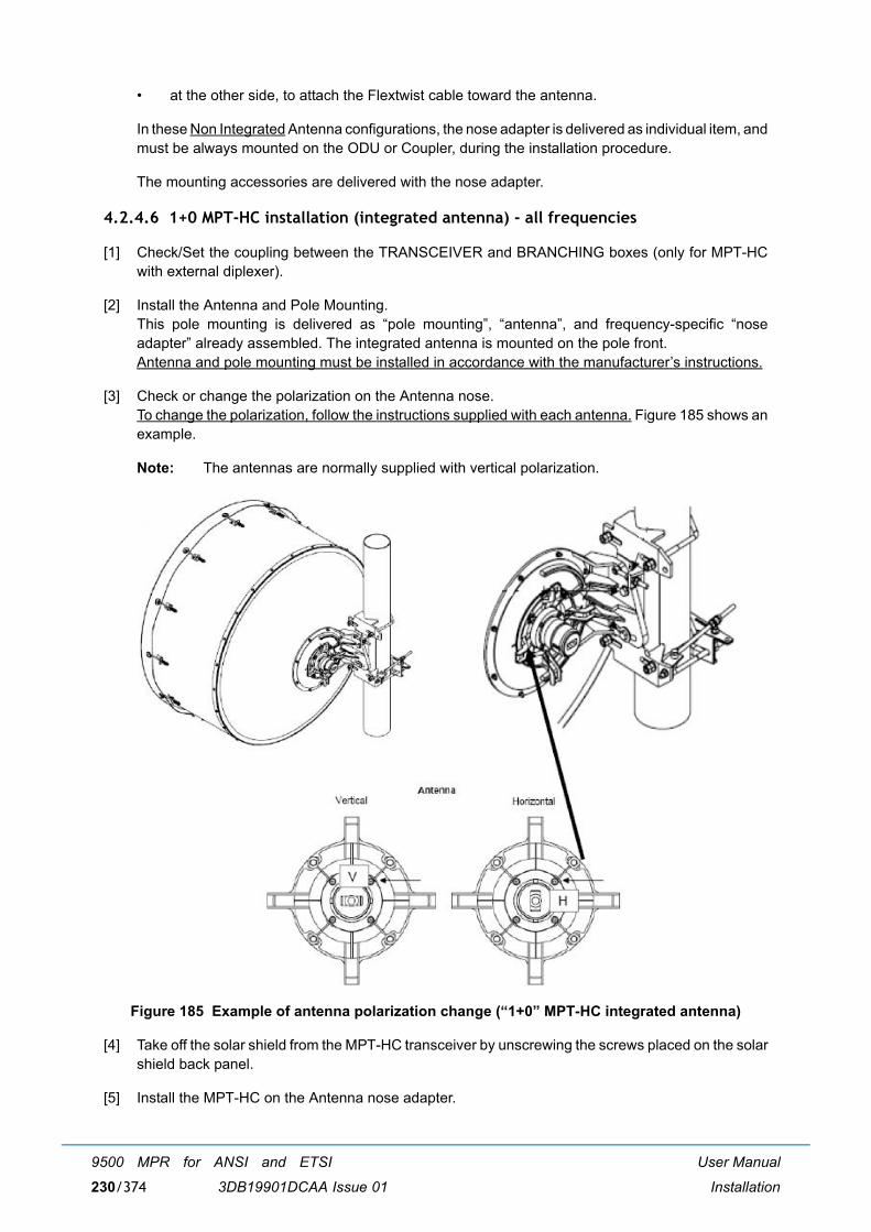
User Manual
Installation
9500 MPR for ANSI and ETSI
3DB19901DCAA Issue 01230/374
� at the other side, to attach the Flextwist cable toward the antenna.
In these Non Integrated Antenna configurations, the nose adapter is delivered as individual item, andmust be always mounted on the ODU or Coupler, during the installation procedure.
The mounting accessories are delivered with the nose adapter.
4.2.4.6 1+0 MPT-HC installation (integrated antenna) - all frequencies
[1] Check/Set the coupling between the TRANSCEIVER and BRANCHING boxes (only for MPT-HCwith external diplexer).
[2] Install the Antenna and Pole Mounting.This pole mounting is delivered as �pole mounting�, �antenna�, and frequency-specific �noseadapter� already assembled. The integrated antenna is mounted on the pole front.Antenna and pole mounting must be installed in accordance with the manufacturer�s instructions.
[3] Check or change the polarization on the Antenna nose.To change the polarization, follow the instructions supplied with each antenna. Figure 185 shows anexample.
Note: The antennas are normally supplied with vertical polarization.
Figure 185 Example of antenna polarization change (�1+0� MPT-HC integrated antenna)
[4] Take off the solar shield from the MPT-HC transceiver by unscrewing the screws placed on the solarshield back panel.
[5] Install the MPT-HC on the Antenna nose adapter.
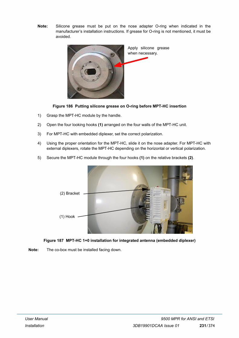
User Manual
Installation
9500 MPR for ANSI and ETSI
3DB19901DCAA Issue 01 231/374
Note: Silicone grease must be put on the nose adapter O-ring when indicated in themanufacturer�s installation instructions. If grease for O-ring is not mentioned, it must beavoided.
Figure 186 Putting silicone grease on O-ring before MPT-HC insertion
1) Grasp the MPT-HC module by the handle.
2) Open the four looking hooks (1) arranged on the four walls of the MPT-HC unit.
3) For MPT-HC with embedded diplexer, set the correct polarization.
4) Using the proper orientation for the MPT-HC, slide it on the nose adapter. For MPT-HC withexternal diplexers, rotate the MPT-HC depending on the horizontal or vertical polarization.
5) Secure the MPT-HC module through the four hooks (1) on the relative brackets (2).
Figure 187 MPT-HC 1+0 installation for integrated antenna (embedded diplexer)
Note: The co-box must be installed facing down.
Apply silicone greasewhen necessary.
(1) Hook
(2) Bracket
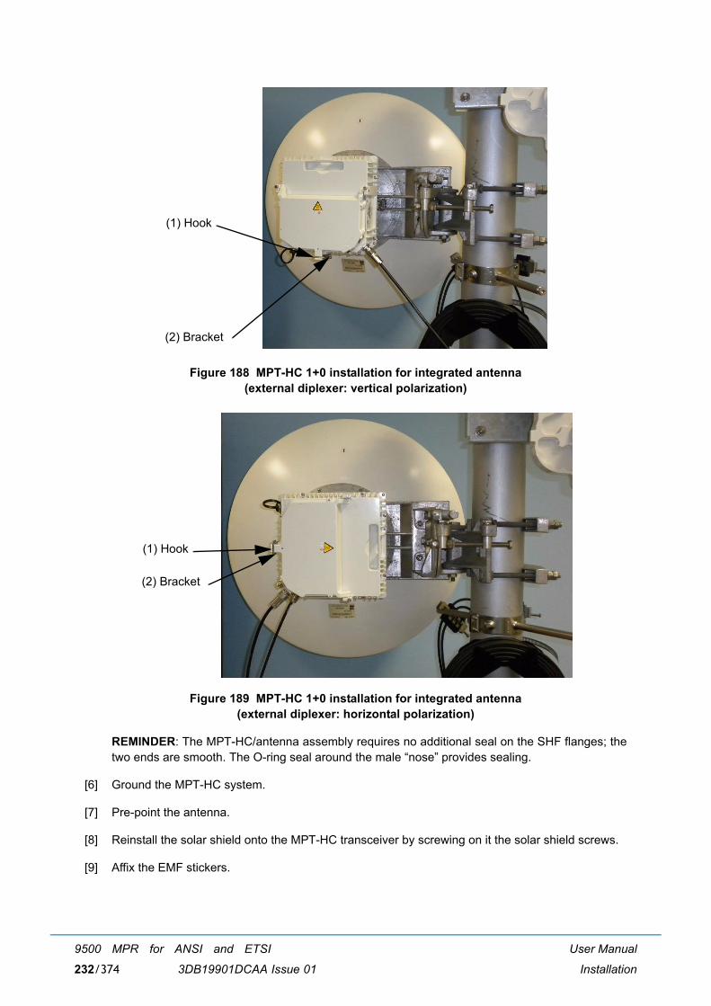
User Manual
Installation
9500 MPR for ANSI and ETSI
3DB19901DCAA Issue 01232/374
Figure 188 MPT-HC 1+0 installation for integrated antenna(external diplexer: vertical polarization)
Figure 189 MPT-HC 1+0 installation for integrated antenna(external diplexer: horizontal polarization)
REMINDER: The MPT-HC/antenna assembly requires no additional seal on the SHF flanges; thetwo ends are smooth. The O-ring seal around the male �nose� provides sealing.
[6] Ground the MPT-HC system.
[7] Pre-point the antenna.
[8] Reinstall the solar shield onto the MPT-HC transceiver by screwing on it the solar shield screws.
[9] Affix the EMF stickers.
(1) Hook
(2) Bracket
(1) Hook
(2) Bracket
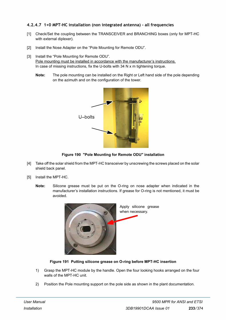
User Manual
Installation
9500 MPR for ANSI and ETSI
3DB19901DCAA Issue 01 233/374
4.2.4.7 1+0 MPT-HC installation (non integrated antenna) - all frequencies
[1] Check/Set the coupling between the TRANSCEIVER and BRANCHING boxes (only for MPT-HCwith external diplexer).
[2] Install the Nose Adapter on the �Pole Mounting for Remote ODU�.
[3] Install the �Pole Mounting for Remote ODU�.Pole mounting must be installed in accordance with the manufacturer�s instructions.In case of missing instructions, fix the U-bolts with 34 N x m tightening torque.
Note: The pole mounting can be installed on the Right or Left hand side of the pole dependingon the azimuth and on the configuration of the tower.
Figure 190 "Pole Mounting for Remote ODU" installation
[4] Take off the solar shield from the MPT-HC transceiver by unscrewing the screws placed on the solarshield back panel.
[5] Install the MPT-HC.
Note: Silicone grease must be put on the O-ring on nose adapter when indicated in themanufacturer�s installation instructions. If grease for O-ring is not mentioned, it must beavoided.
Figure 191 Putting silicone grease on O-ring before MPT-HC insertion
1) Grasp the MPT-HC module by the handle. Open the four looking hooks arranged on the fourwalls of the MPT-HC unit.
2) Position the Pole mounting support on the pole side as shown in the plant documentation.
Apply silicone greasewhen necessary.
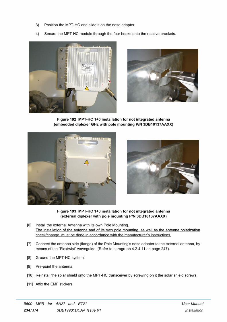
User Manual
Installation
9500 MPR for ANSI and ETSI
3DB19901DCAA Issue 01234/374
3) Position the MPT-HC and slide it on the nose adapter.
4) Secure the MPT-HC module through the four hooks onto the relative brackets.
Figure 192 MPT-HC 1+0 installation for not integrated antenna(embedded diplexer GHz with pole mounting P/N 3DB10137AAXX)
Figure 193 MPT-HC 1+0 installation for not integrated antenna(external diplexer with pole mounting P/N 3DB10137AAXX)
[6] Install the external Antenna with its own Pole Mounting.The installation of the antenna and of its own pole mounting, as well as the antenna polarizationcheck/change, must be done in accordance with the manufacturer�s instructions.
[7] Connect the antenna side (flange) of the Pole Mounting�s nose adapter to the external antenna, bymeans of the �Flextwist� waveguide. (Refer to paragraph 4.2.4.11 on page 247).
[8] Ground the MPT-HC system.
[9] Pre-point the antenna.
[10] Reinstall the solar shield onto the MPT-HC transceiver by screwing on it the solar shield screws.
[11] Affix the EMF stickers.
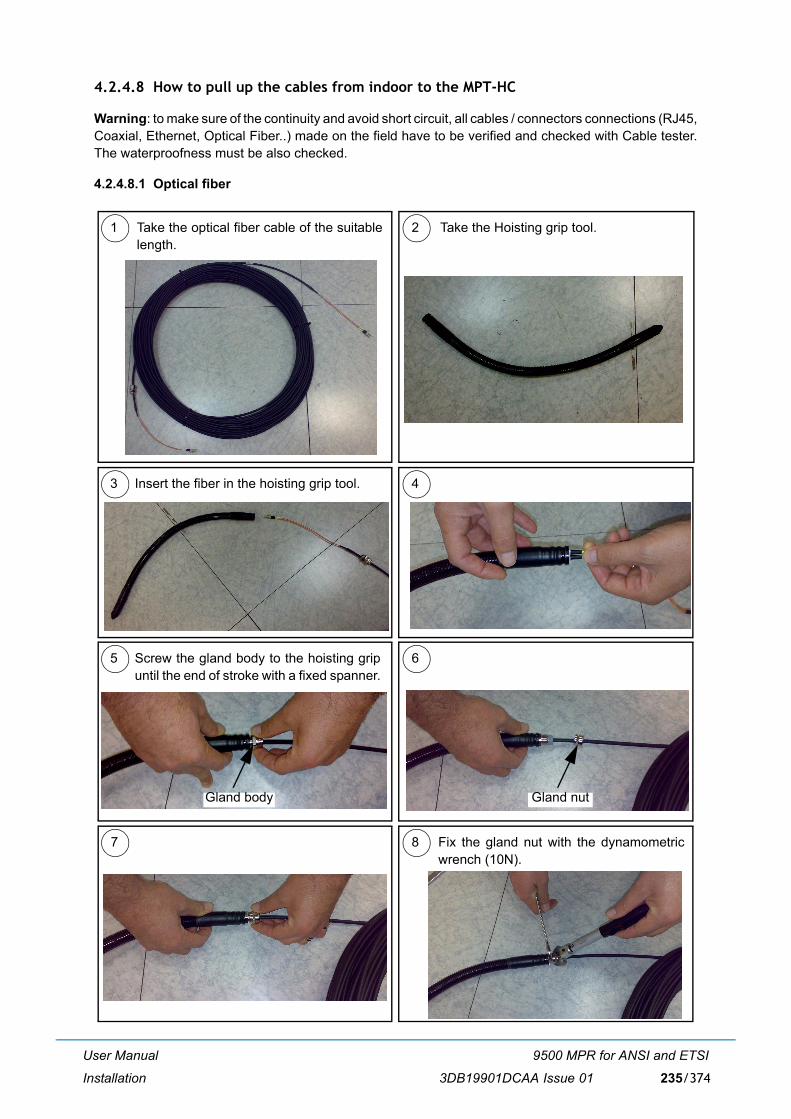
User Manual
Installation
9500 MPR for ANSI and ETSI
3DB19901DCAA Issue 01 235/374
4.2.4.8 How to pull up the cables from indoor to the MPT-HC
Warning: to make sure of the continuity and avoid short circuit, all cables / connectors connections (RJ45,Coaxial, Ethernet, Optical Fiber..) made on the field have to be verified and checked with Cable tester.The waterproofness must be also checked.
4.2.4.8.1 Optical fiber
1 2
3 4
Take the optical fiber cable of the suitablelength.
Take the Hoisting grip tool.
Insert the fiber in the hoisting grip tool.
5 6Screw the gland body to the hoisting gripuntil the end of stroke with a fixed spanner.
7 8 Fix the gland nut with the dynamometricwrench (10N).
Gland nutGland body
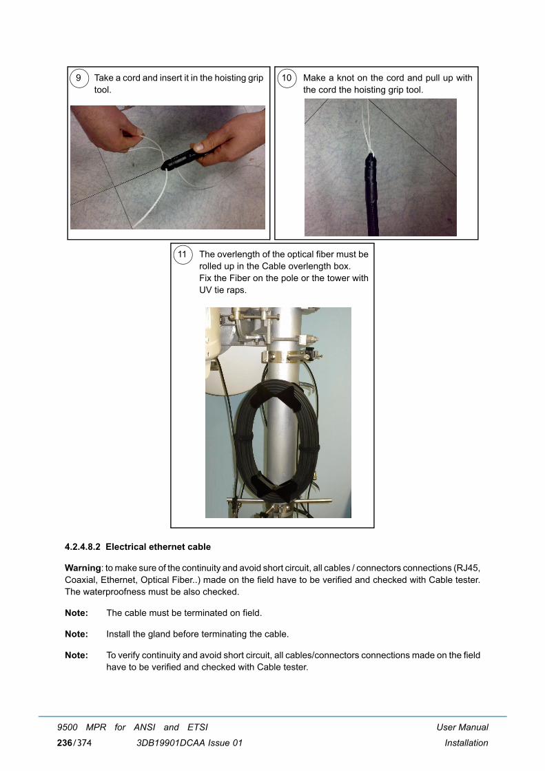
User Manual
Installation
9500 MPR for ANSI and ETSI
3DB19901DCAA Issue 01236/374
4.2.4.8.2 Electrical ethernet cable
Warning: to make sure of the continuity and avoid short circuit, all cables / connectors connections (RJ45,Coaxial, Ethernet, Optical Fiber..) made on the field have to be verified and checked with Cable tester.The waterproofness must be also checked.
Note: The cable must be terminated on field.
Note: Install the gland before terminating the cable.
Note: To verify continuity and avoid short circuit, all cables/connectors connections made on the fieldhave to be verified and checked with Cable tester.
9 10Take a cord and insert it in the hoisting griptool.
Make a knot on the cord and pull up withthe cord the hoisting grip tool.
11 The overlength of the optical fiber must berolled up in the Cable overlength box.Fix the Fiber on the pole or the tower withUV tie raps.
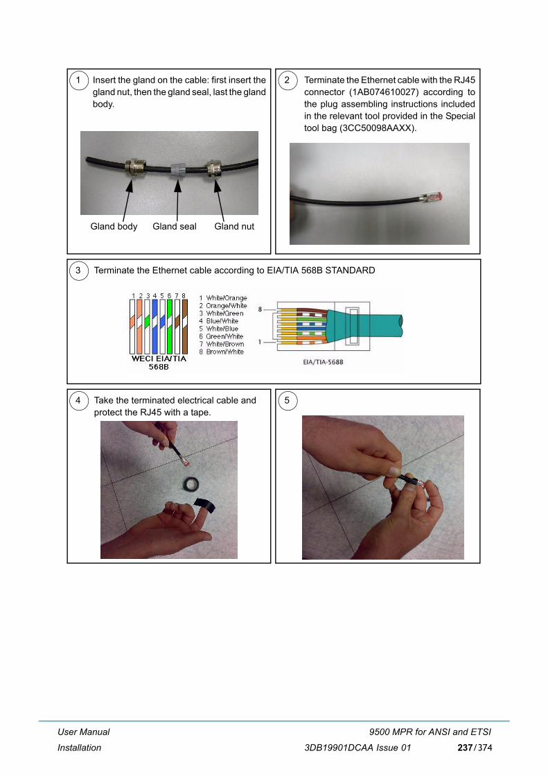
User Manual
Installation
9500 MPR for ANSI and ETSI
3DB19901DCAA Issue 01 237/374
4 5Take the terminated electrical cable andprotect the RJ45 with a tape.
1 Insert the gland on the cable: first insert thegland nut, then the gland seal, last the glandbody.
Terminate the Ethernet cable with the RJ45connector (1AB074610027) according tothe plug assembling instructions includedin the relevant tool provided in the Specialtool bag (3CC50098AAXX).
2
Gland body Gland seal Gland nut
3 Terminate the Ethernet cable according to EIA/TIA 568B STANDARD
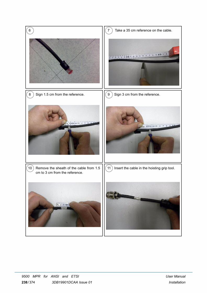
User Manual
Installation
9500 MPR for ANSI and ETSI
3DB19901DCAA Issue 01238/374
8 9Sign 1.5 cm from the reference. Sign 3 cm from the reference.
10 11Remove the sheath of the cable from 1.5cm to 3 cm from the reference.
Insert the cable in the hoisting grip tool.
6 7 Take a 35 cm reference on the cable.
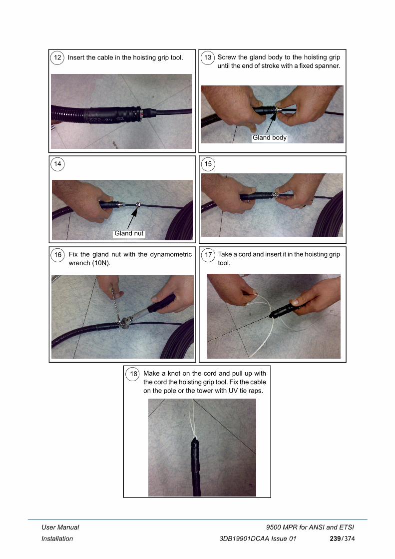
User Manual
Installation
9500 MPR for ANSI and ETSI
3DB19901DCAA Issue 01 239/374
Make a knot on the cord and pull up withthe cord the hoisting grip tool. Fix the cableon the pole or the tower with UV tie raps.
18
Take a cord and insert it in the hoisting griptool.
14 15
16 17
Gland nut
Fix the gland nut with the dynamometricwrench (10N).
12 13Insert the cable in the hoisting grip tool. Screw the gland body to the hoisting gripuntil the end of stroke with a fixed spanner.
Gland body
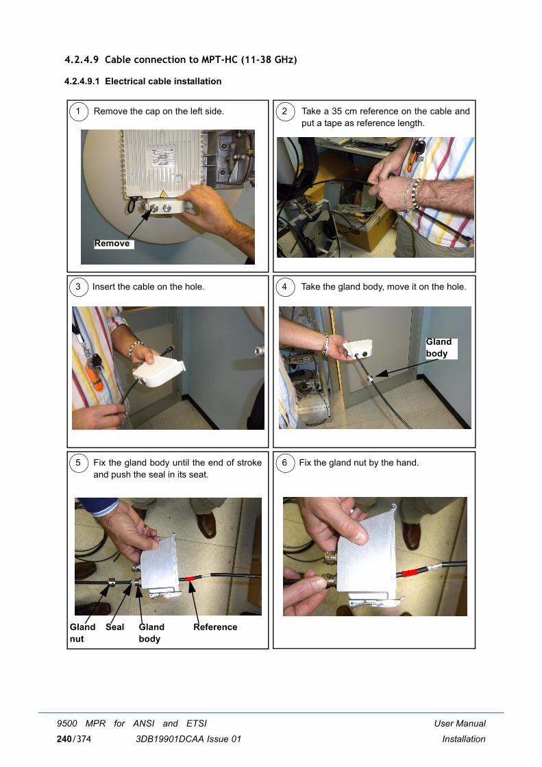
User Manual
Installation
9500 MPR for ANSI and ETSI
3DB19901DCAA Issue 01240/374
4.2.4.9 Cable connection to MPT-HC (11-38 GHz)
4.2.4.9.1 Electrical cable installation
1 2
3 4
5 6
Remove the cap on the left side. Take a 35 cm reference on the cable andput a tape as reference length.
Insert the cable on the hole. Take the gland body, move it on the hole.
Glandbody
Fix the gland body until the end of strokeand push the seal in its seat.
Fix the gland nut by the hand.
Remove
Glandnut
Glandbody
Seal Reference
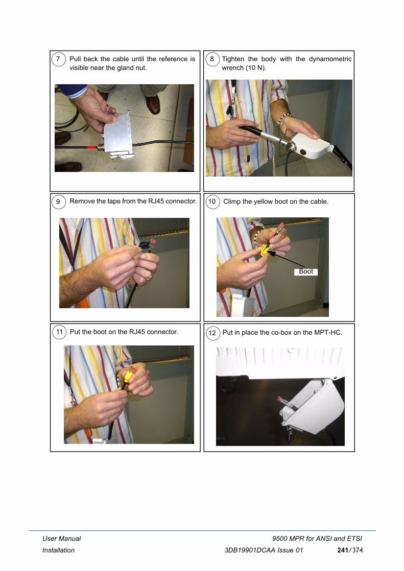
User Manual
Installation
9500 MPR for ANSI and ETSI
3DB19901DCAA Issue 01 241/374
Put in place the co-box on the MPT-HC.
Remove the tape from the RJ45 connector. 10
11
Climp the yellow boot on the cable.
Put the boot on the RJ45 connector. 12
9
Boot
7 8Pull back the cable until the reference isvisible near the gland nut.
Tighten the body with the dynamometricwrench (10 N).
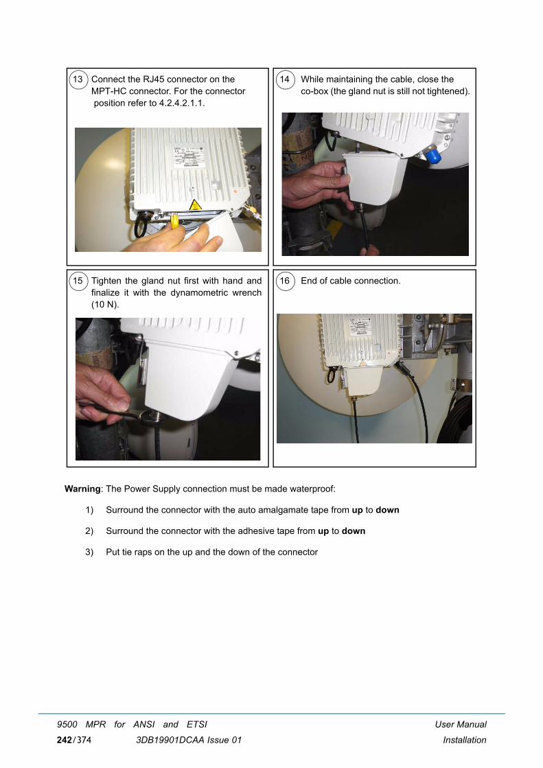
User Manual
Installation
9500 MPR for ANSI and ETSI
3DB19901DCAA Issue 01242/374
Warning: The Power Supply connection must be made waterproof:
1) Surround the connector with the auto amalgamate tape from up to down
2) Surround the connector with the adhesive tape from up to down
3) Put tie raps on the up and the down of the connector
13 14 While maintaining the cable, close the co-box (the gland nut is still not tightened).
Connect the RJ45 connector on the MPT-HC connector. For the connector position refer to 4.2.4.2.1.1.
15 16 End of cable connection.Tighten the gland nut first with hand andfinalize it with the dynamometric wrench(10 N).
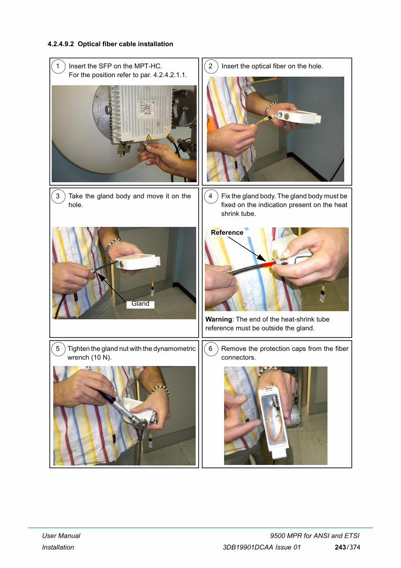
User Manual
Installation
9500 MPR for ANSI and ETSI
3DB19901DCAA Issue 01 243/374
4.2.4.9.2 Optical fiber cable installation
1 2
3 4
5 6
Insert the SFP on the MPT-HC.For the position refer to par. 4.2.4.2.1.1.
Insert the optical fiber on the hole.
Gland
Fix the gland body. The gland body must befixed on the indication present on the heatshrink tube.
Take the gland body and move it on thehole.
Tighten the gland nut with the dynamometricwrench (10 N).
Remove the protection caps from the fiberconnectors.
Warning: The end of the heat-shrink tube reference must be outside the gland.
Reference
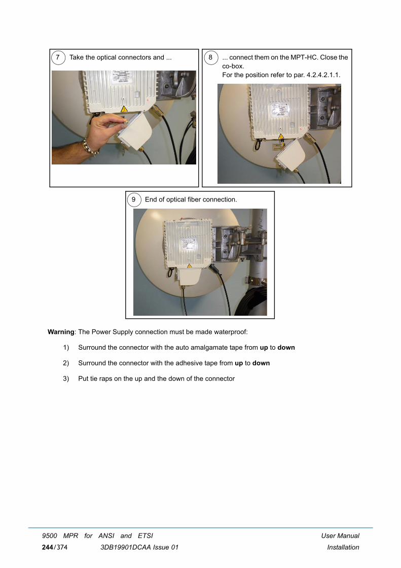
User Manual
Installation
9500 MPR for ANSI and ETSI
3DB19901DCAA Issue 01244/374
Warning: The Power Supply connection must be made waterproof:
1) Surround the connector with the auto amalgamate tape from up to down
2) Surround the connector with the adhesive tape from up to down
3) Put tie raps on the up and the down of the connector
7 8
9
Take the optical connectors and ... ... connect them on the MPT-HC. Close theco-box. For the position refer to par. 4.2.4.2.1.1.
End of optical fiber connection.
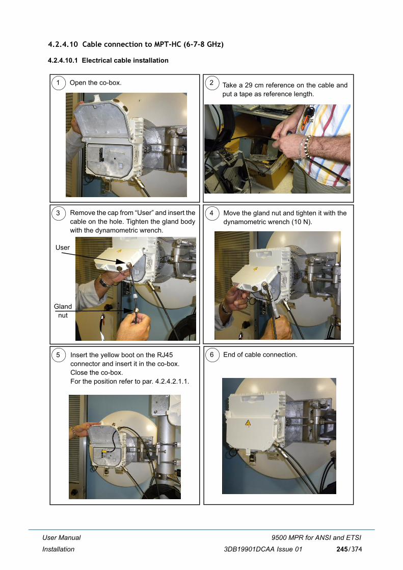
User Manual
Installation
9500 MPR for ANSI and ETSI
3DB19901DCAA Issue 01 245/374
4.2.4.10 Cable connection to MPT-HC (6-7-8 GHz)
4.2.4.10.1 Electrical cable installation
1 2
3 4
6
Open the co-box.
Move the gland nut and tighten it with the dynamometric wrench (10 N).
End of cable connection.5 Insert the yellow boot on the RJ45 connector and insert it in the co-box. Close the co-box.For the position refer to par. 4.2.4.2.1.1.
Remove the cap from �User� and insert thecable on the hole. Tighten the gland bodywith the dynamometric wrench.
User
Gland nut
Take a 29 cm reference on the cable andput a tape as reference length.
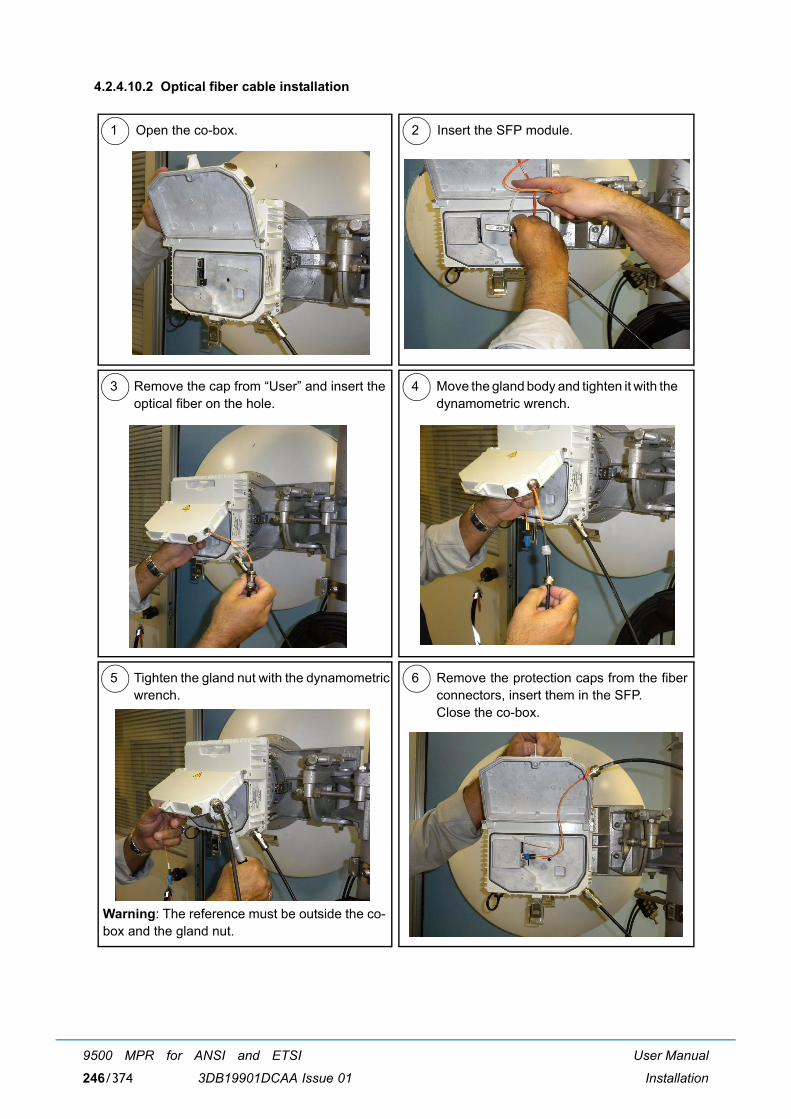
User Manual
Installation
9500 MPR for ANSI and ETSI
3DB19901DCAA Issue 01246/374
4.2.4.10.2 Optical fiber cable installation
1 2
3 4
5 6
Open the co-box. Insert the SFP module.
Move the gland body and tighten it with the dynamometric wrench.
Remove the cap from �User� and insert theoptical fiber on the hole.
Tighten the gland nut with the dynamometricwrench.
Remove the protection caps from the fiberconnectors, insert them in the SFP. Close the co-box.
Warning: The reference must be outside the co-box and the gland nut.
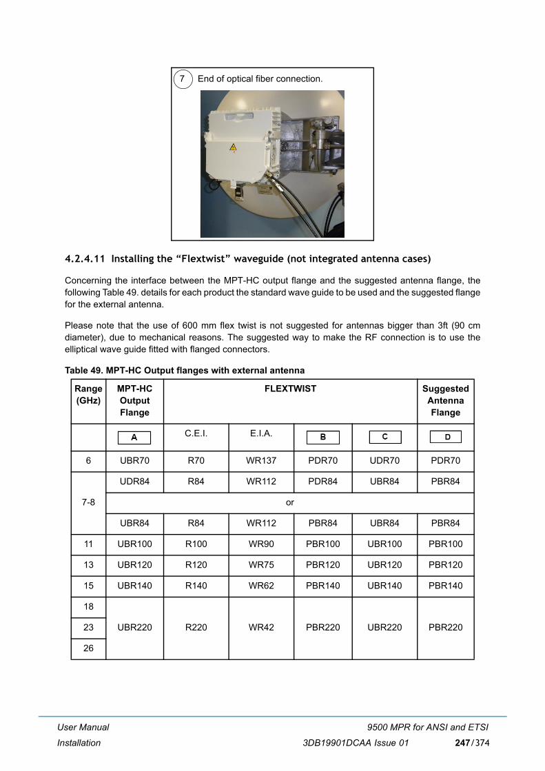
User Manual
Installation
9500 MPR for ANSI and ETSI
3DB19901DCAA Issue 01 247/374
4.2.4.11 Installing the �Flextwist� waveguide (not integrated antenna cases)
Concerning the interface between the MPT-HC output flange and the suggested antenna flange, thefollowing Table 49. details for each product the standard wave guide to be used and the suggested flangefor the external antenna.
Please note that the use of 600 mm flex twist is not suggested for antennas bigger than 3ft (90 cmdiameter), due to mechanical reasons. The suggested way to make the RF connection is to use theelliptical wave guide fitted with flanged connectors.
Table 49. MPT-HC Output flanges with external antenna
Range (GHz)
MPT-HC Output Flange
FLEXTWIST Suggested Antenna Flange
C.E.I. E.I.A.
6 UBR70 R70 WR137 PDR70 UDR70 PDR70
7-8
UDR84 R84 WR112 PDR84 UBR84 PBR84
or
UBR84 R84 WR112 PBR84 UBR84 PBR84
11 UBR100 R100 WR90 PBR100 UBR100 PBR100
13 UBR120 R120 WR75 PBR120 UBR120 PBR120
15 UBR140 R140 WR62 PBR140 UBR140 PBR140
18
UBR220 R220 WR42 PBR220 UBR220 PBR22023
26
7 End of optical fiber connection.
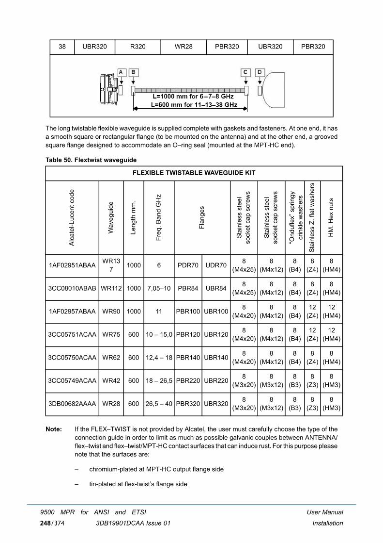
User Manual
Installation
9500 MPR for ANSI and ETSI
3DB19901DCAA Issue 01248/374
The long twistable flexible waveguide is supplied complete with gaskets and fasteners. At one end, it hasa smooth square or rectangular flange (to be mounted on the antenna) and at the other end, a groovedsquare flange designed to accommodate an O�ring seal (mounted at the MPT-HC end).
Table 50. Flextwist waveguide
Note: If the FLEX�TWIST is not provided by Alcatel, the user must carefully choose the type of theconnection guide in order to limit as much as possible galvanic couples between ANTENNA/flex�twist and flex�twist/MPT-HC contact surfaces that can induce rust. For this purpose pleasenote that the surfaces are:
� chromium-plated at MPT-HC output flange side
� tin-plated at flex-twist�s flange side
38 UBR320 R320 WR28 PBR320 UBR320 PBR320
FLEXIBLE TWISTABLE WAVEGUIDE KIT
Alc
atel
-Luc
ent c
ode
Wav
egui
de
Leng
th m
m.
Freq
. Ban
d G
Hz
Flan
ges
Stai
nles
s st
eel
sock
et c
ap s
crew
s
Stai
nles
s st
eel
sock
et c
ap s
crew
s
�Ond
ufle
x� s
prin
gy
crin
kle
was
hers
Stai
nles
s Z.
flat
was
hers
HM
. Hex
nut
s
1AF02951ABAA WR137 1000 6 PDR70 UDR70 8
(M4x25)8
(M4x12)8
(B4)8
(Z4)8
(HM4)
3CC08010ABAB WR112 1000 7,05�10 PBR84 UBR84 8 (M4x25)
8 (M4x12)
8 (B4)
8 (Z4)
8 (HM4)
1AF02957ABAA WR90 1000 11 PBR100 UBR100 8 (M4x20)
8 (M4x12)
8 (B4)
12 (Z4)
12 (HM4)
3CC05751ACAA WR75 600 10 � 15,0 PBR120 UBR120 8 (M4x20)
8 (M4x12)
8 (B4)
12 (Z4)
12 (HM4)
3CC05750ACAA WR62 600 12,4 � 18 PBR140 UBR140 8 (M4x20)
8 (M4x12)
8 (B4)
8 (Z4)
8 (HM4)
3CC05749ACAA WR42 600 18 � 26,5 PBR220 UBR220 8 (M3x20)
8 (M3x12)
8 (B3)
8 (Z3)
8 (HM3)
3DB00682AAAA WR28 600 26,5 � 40 PBR320 UBR320 8 (M3x20)
8 (M3x12)
8 (B3)
8 (Z3)
8 (HM3)

User Manual
Installation
9500 MPR for ANSI and ETSI
3DB19901DCAA Issue 01 249/374
4.2.4.12 MPT-HC system grounding
Each MPT-HC transceiver must be individually grounded.
Note: Neither the RF coupler, nor the antenna(s), integrated or not integrated, must be grounded.
The following items are necessary for the individual grounding of each MPT-HC transceiver:
� one MPT-HC Grounding cable 16 mm2 (P/N 1AC001060084).This 16 mm2 cable must be cut on site and connected to the terminal provided on the MPT-HCtransceiver, and, on the other side, to the nearest grounding plate;
This example figure shows the grounding connector position.
Figure 194 MPT-HC system ground connector
Connect all grounding cables to the nearest grounding plate, as shown in this example:
Figure 195 Example 9500 MPR/9558HC system ground plate
4.2.4.13 Cable grounding
The Power Supply cable and the Ethernet electrical cable must be grounded by using the dedicatedGrounding kits.
For ground kit installation instructions refer to the guide provided with each kit.
For tower/mast installations the cables must be grounded at:
� The point where it comes on to the tower from the MPT-HC
� The point where it leaves the tower to go to the equipment building
MPT-HC grounding connector:to be connected with thegrounding cable to the nearestgrounding plate
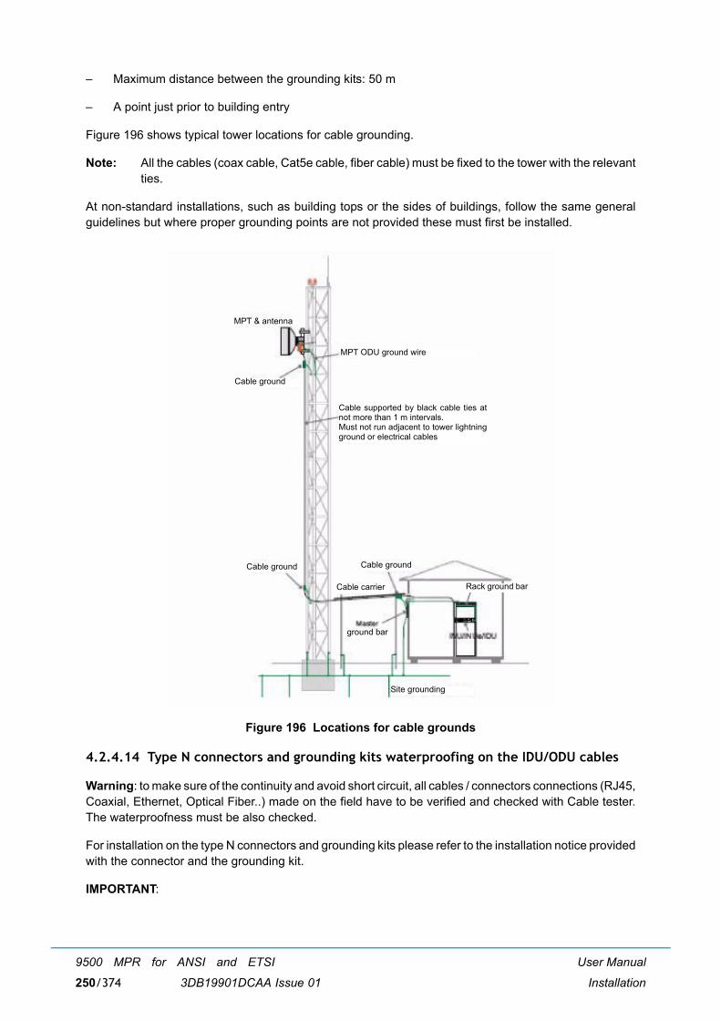
User Manual
Installation
9500 MPR for ANSI and ETSI
3DB19901DCAA Issue 01250/374
� Maximum distance between the grounding kits: 50 m
� A point just prior to building entry
Figure 196 shows typical tower locations for cable grounding.
Note: All the cables (coax cable, Cat5e cable, fiber cable) must be fixed to the tower with the relevantties.
At non-standard installations, such as building tops or the sides of buildings, follow the same generalguidelines but where proper grounding points are not provided these must first be installed.
Figure 196 Locations for cable grounds
4.2.4.14 Type N connectors and grounding kits waterproofing on the IDU/ODU cables
Warning: to make sure of the continuity and avoid short circuit, all cables / connectors connections (RJ45,Coaxial, Ethernet, Optical Fiber..) made on the field have to be verified and checked with Cable tester.The waterproofness must be also checked.
For installation on the type N connectors and grounding kits please refer to the installation notice providedwith the connector and the grounding kit.
IMPORTANT:
MPT & antenna
Cable ground
MPT ODU ground wire
Cable ground Cable ground
Cable carrier
ground bar
Site grounding
Rack ground bar
Cable supported by black cable ties atnot more than 1 m intervals. Must not run adjacent to tower lightningground or electrical cables
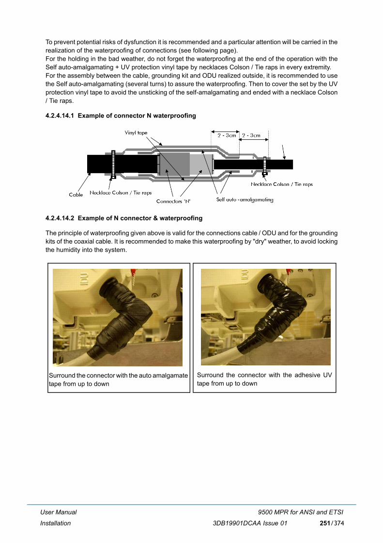
User Manual
Installation
9500 MPR for ANSI and ETSI
3DB19901DCAA Issue 01 251/374
To prevent potential risks of dysfunction it is recommended and a particular attention will be carried in therealization of the waterproofing of connections (see following page).For the holding in the bad weather, do not forget the waterproofing at the end of the operation with theSelf auto-amalgamating + UV protection vinyl tape by necklaces Colson / Tie raps in every extremity.For the assembly between the cable, grounding kit and ODU realized outside, it is recommended to usethe Self auto-amalgamating (several turns) to assure the waterproofing. Then to cover the set by the UVprotection vinyl tape to avoid the unsticking of the self-amalgamating and ended with a necklace Colson/ Tie raps.
4.2.4.14.1 Example of connector N waterproofing
4.2.4.14.2 Example of N connector & waterproofing
The principle of waterproofing given above is valid for the connections cable / ODU and for the groundingkits of the coaxial cable. It is recommended to make this waterproofing by "dry" weather, to avoid lockingthe humidity into the system.
Surround the connector with the adhesive UVtape from up to down
Surround the connector with the auto amalgamatetape from up to down
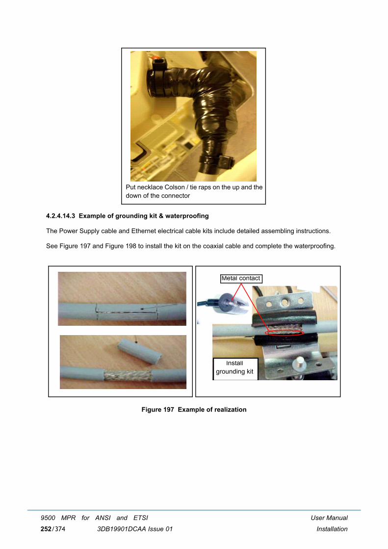
User Manual
Installation
9500 MPR for ANSI and ETSI
3DB19901DCAA Issue 01252/374
4.2.4.14.3 Example of grounding kit & waterproofing
The Power Supply cable and Ethernet electrical cable kits include detailed assembling instructions.
See Figure 197 and Figure 198 to install the kit on the coaxial cable and complete the waterproofing.
Figure 197 Example of realization
Put necklace Colson / tie raps on the up and thedown of the connector
Metal contact
Install grounding kit
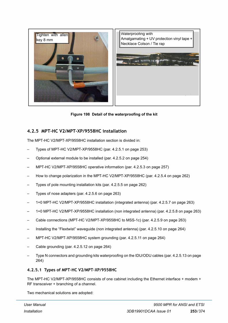
User Manual
Installation
9500 MPR for ANSI and ETSI
3DB19901DCAA Issue 01 253/374
Figure 198 Detail of the waterproofing of the kit
4.2.5 MPT-HC V2/MPT-XP/9558HC installation
The MPT-HC V2/MPT-XP/9558HC installation section is divided in:
� Types of MPT-HC V2/MPT-XP/9558HC (par. 4.2.5.1 on page 253)
� Optional external module to be installed (par. 4.2.5.2 on page 254)
� MPT-HC V2/MPT-XP/9558HC operative information (par. 4.2.5.3 on page 257)
� How to change polarization in the MPT-HC V2/MPT-XP/9558HC (par. 4.2.5.4 on page 262)
� Types of pole mounting installation kits (par. 4.2.5.5 on page 262)
� Types of nose adapters (par. 4.2.5.6 on page 263)
� 1+0 MPT-HC V2/MPT-XP/9558HC installation (integrated antenna) (par. 4.2.5.7 on page 263)
� 1+0 MPT-HC V2/MPT-XP/9558HC installation (non integrated antenna) (par. 4.2.5.8 on page 263)
� Cable connections (MPT-HC V2/MPT-XP/9558HC to MSS-1c) (par. 4.2.5.9 on page 263)
� Installing the �Flextwist� waveguide (non integrated antenna) (par. 4.2.5.10 on page 264)
� MPT-HC V2/MPT-XP/9558HC system grounding (par. 4.2.5.11 on page 264)
� Cable grounding (par. 4.2.5.12 on page 264)
� Type N connectors and grounding kits waterproofing on the IDU/ODU cables (par. 4.2.5.13 on page264)
4.2.5.1 Types of MPT-HC V2/MPT-XP/9558HC
The MPT-HC V2/MPT-XP/9558HC consists of one cabinet including the Ethernet interface + modem +RF transceiver + branching of a channel.
Two mechanical solutions are adopted:
Waterproofing with Amalgamating + UV protection vinyl tape +Necklace Colson / Tie rap
Tighten with allenkey 8 mm
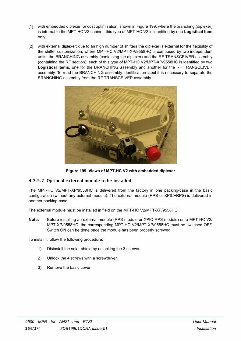
User Manual
Installation
9500 MPR for ANSI and ETSI
3DB19901DCAA Issue 01254/374
[1] with embedded diplexer for cost optimisation, shown in Figure 199, where the branching (diplexer)is internal to the MPT-HC V2 cabinet; this type of MPT-HC V2 is identified by one Logistical Itemonly;
[2] with external diplexer: due to an high number of shifters the diplexer is external for the flexibility ofthe shifter customization, where MPT-HC V2/MPT-XP/9558HC is composed by two independentunits: the BRANCHING assembly (containing the diplexer) and the RF TRANSCEIVER assembly(containing the RF section); each of this type of MPT-HC V2/MPT-XP/9558HC is identified by twoLogistical Items, one for the BRANCHING assembly and another for the RF TRANSCEIVERassembly. To read the BRANCHING assembly identification label it is necessary to separate theBRANCHING assembly from the RF TRANSCEIVER assembly.
Figure 199 Views of MPT-HC V2 with embedded diplexer
4.2.5.2 Optional external module to be installed
The MPT-HC V2/MPT-XP/9558HC is delivered from the factory in one packing-case in the basicconfiguration (without any external module). The external module (RPS or XPIC+RPS) is delivered inanother packing-case.
The external module must be installed in field on the MPT-HC V2/MPT-XP/9558HC.
Note: Before installing an external module (RPS module or XPIC-RPS module) on a MPT-HC V2/MPT-XP/9558HC, the corresponding MPT-HC V2/MPT-XP/9558HC must be switched OFF.Switch ON can be done once the module has been properly screwed.
To install it follow the following procedure:
1) Disinstall the solar shield by unlocking the 3 screws.
2) Unlock the 4 screws with a screwdriver.
3) Remove the basic cover
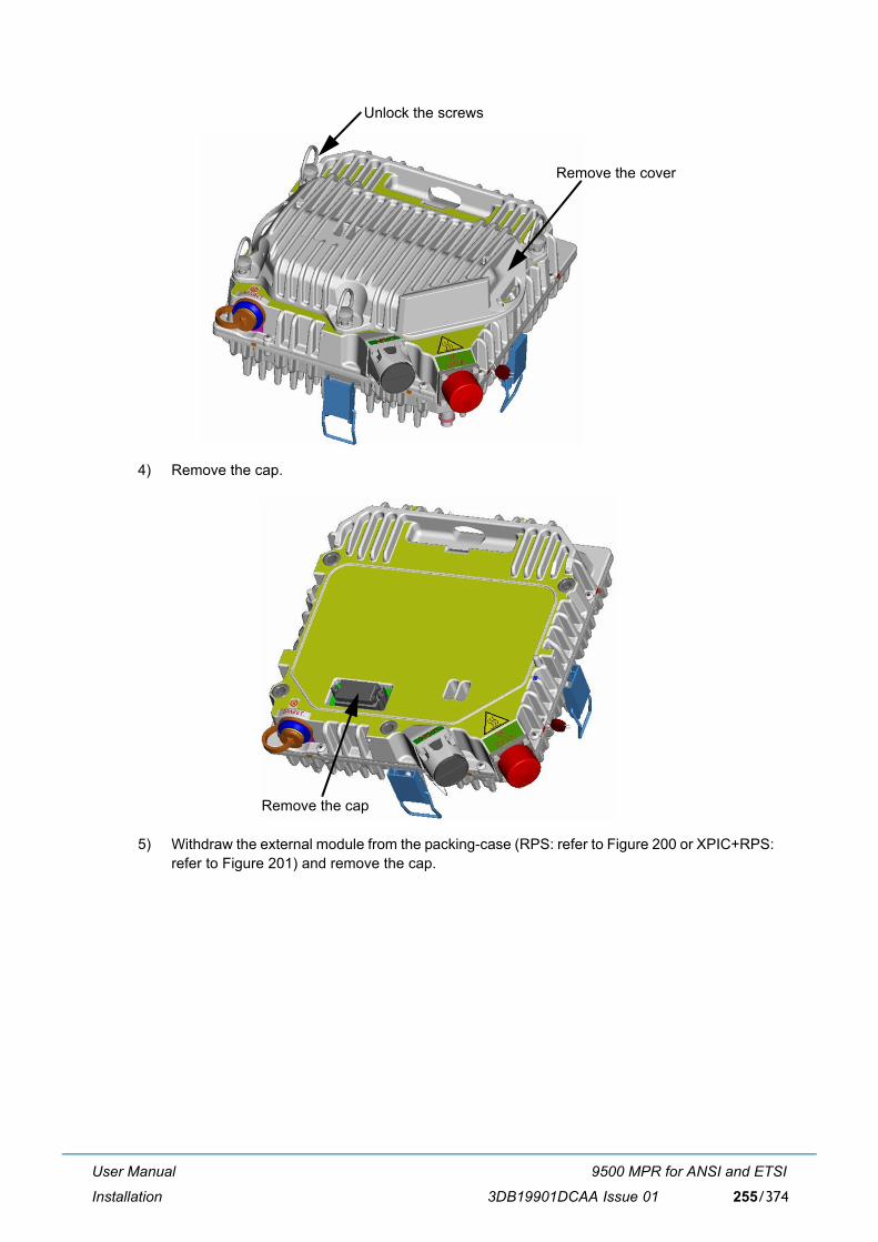
User Manual
Installation
9500 MPR for ANSI and ETSI
3DB19901DCAA Issue 01 255/374
4) Remove the cap.
5) Withdraw the external module from the packing-case (RPS: refer to Figure 200 or XPIC+RPS:refer to Figure 201) and remove the cap.
Unlock the screws
Remove the cover
Remove the cap
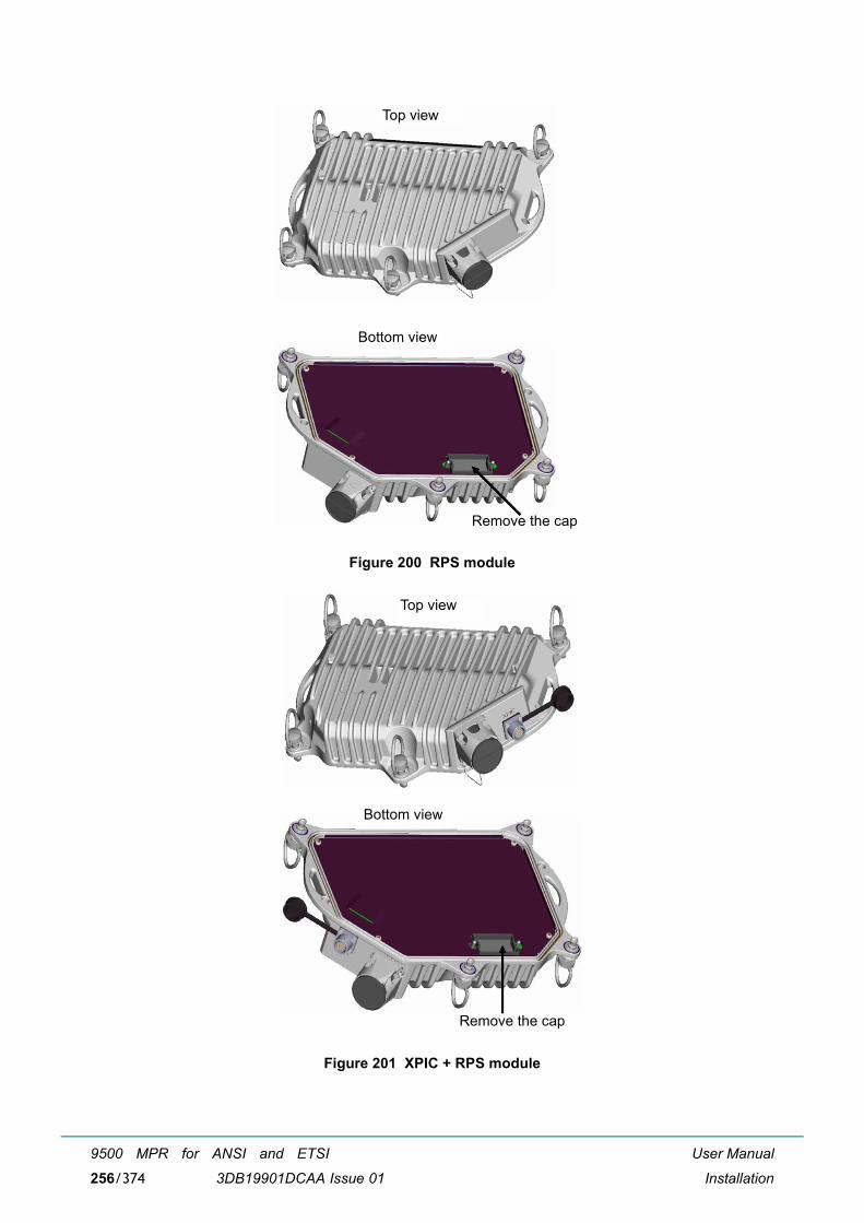
User Manual
Installation
9500 MPR for ANSI and ETSI
3DB19901DCAA Issue 01256/374
Figure 200 RPS module
Figure 201 XPIC + RPS module
Remove the cap
Bottom view
Top view
Remove the cap
Bottom view
Top view
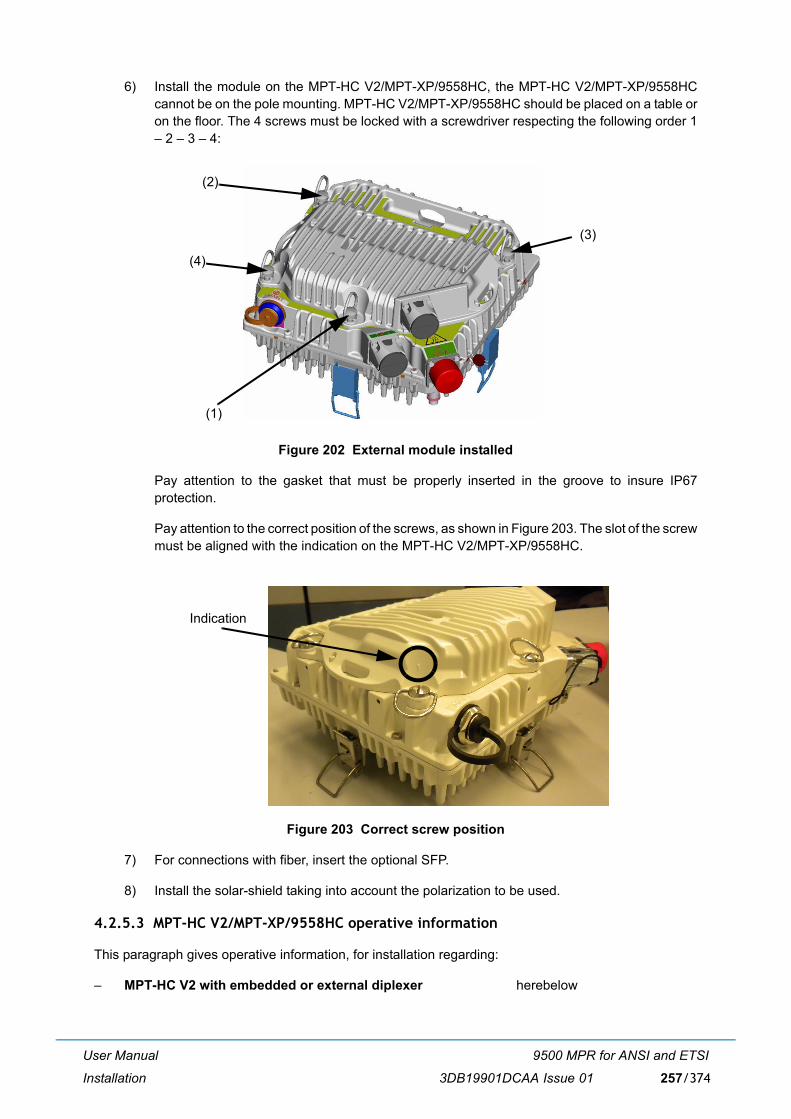
User Manual
Installation
9500 MPR for ANSI and ETSI
3DB19901DCAA Issue 01 257/374
6) Install the module on the MPT-HC V2/MPT-XP/9558HC, the MPT-HC V2/MPT-XP/9558HCcannot be on the pole mounting. MPT-HC V2/MPT-XP/9558HC should be placed on a table oron the floor. The 4 screws must be locked with a screwdriver respecting the following order 1� 2 � 3 � 4:
Figure 202 External module installed
Pay attention to the gasket that must be properly inserted in the groove to insure IP67protection.
Pay attention to the correct position of the screws, as shown in Figure 203. The slot of the screwmust be aligned with the indication on the MPT-HC V2/MPT-XP/9558HC.
Figure 203 Correct screw position
7) For connections with fiber, insert the optional SFP.
8) Install the solar-shield taking into account the polarization to be used.
4.2.5.3 MPT-HC V2/MPT-XP/9558HC operative information
This paragraph gives operative information, for installation regarding:
� MPT-HC V2 with embedded or external diplexer herebelow
(1)
(2)
(4)
(3)
Indication
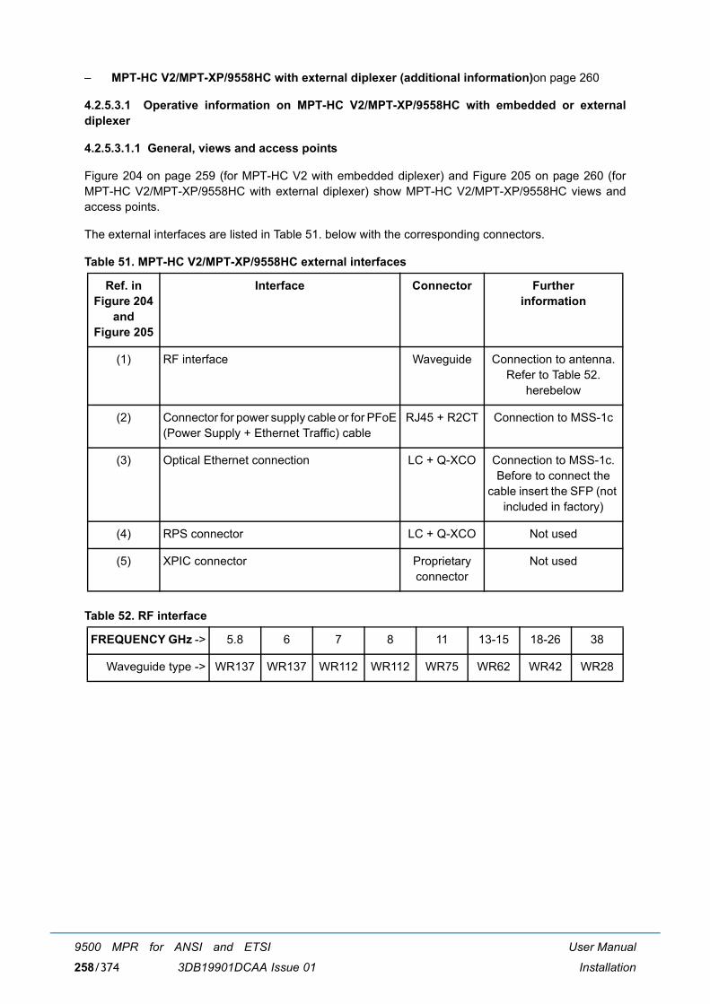
User Manual
Installation
9500 MPR for ANSI and ETSI
3DB19901DCAA Issue 01258/374
� MPT-HC V2/MPT-XP/9558HC with external diplexer (additional information)on page 260
4.2.5.3.1 Operative information on MPT-HC V2/MPT-XP/9558HC with embedded or externaldiplexer
4.2.5.3.1.1 General, views and access points
Figure 204 on page 259 (for MPT-HC V2 with embedded diplexer) and Figure 205 on page 260 (forMPT-HC V2/MPT-XP/9558HC with external diplexer) show MPT-HC V2/MPT-XP/9558HC views andaccess points.
The external interfaces are listed in Table 51. below with the corresponding connectors.
Table 51. MPT-HC V2/MPT-XP/9558HC external interfaces
Table 52. RF interface
Ref. in Figure 204
and Figure 205
Interface Connector Further information
(1) RF interface Waveguide Connection to antenna. Refer to Table 52.
herebelow
(2) Connector for power supply cable or for PFoE(Power Supply + Ethernet Traffic) cable
RJ45 + R2CT Connection to MSS-1c
(3) Optical Ethernet connection LC + Q-XCO Connection to MSS-1c.Before to connect the
cable insert the SFP (not included in factory)
(4) RPS connector LC + Q-XCO Not used
(5) XPIC connector Proprietary connector
Not used
FREQUENCY GHz -> 5.8 6 7 8 11 13-15 18-26 38
Waveguide type -> WR137 WR137 WR112 WR112 WR75 WR62 WR42 WR28
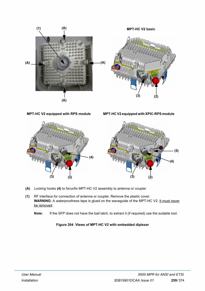
User Manual
Installation
9500 MPR for ANSI and ETSI
3DB19901DCAA Issue 01 259/374
Figure 204 Views of MPT-HC V2 with embedded diplexer
(A) Locking hooks (4) to fix/unfix MPT-HC V2 assembly to antenna or coupler
(1) RF interface for connection of antenna or coupler. Remove the plastic cover.WARNING: A waterproofness tape is glued on the waveguide of the MPT-HC V2. It must neverbe removed.
Note: If the SFP does not have the bail latch, to extract it (if required) use the suitable tool.
(1) (A)
(A)(A)
(A)(3) (2)
MPT-HC V2 basic
(4)
(3) (2)
MPT-HC V2 equipped with XPIC-RPS module
(5)
(4)
(3) (2)
MPT-HC V2 equipped with RPS module
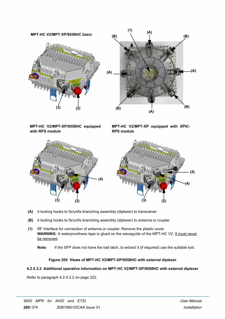
User Manual
Installation
9500 MPR for ANSI and ETSI
3DB19901DCAA Issue 01260/374
Figure 205 Views of MPT-HC V2/MPT-XP/9558HC with external diplexer
4.2.5.3.2 Additional operative information on MPT-HC V2/MPT-XP/9558HC with external diplexer
Refer to paragraph 4.2.4.2.2 on page 222.
(A) 4 locking hooks to fix/unfix branching assembly (diplexer) to transceiver
(B) 4 locking hooks to fix/unfix branching assembly (diplexer) to antenna or coupler
(1) RF interface for connection of antenna or coupler. Remove the plastic cover.WARNING: A waterproofness tape is glued on the waveguide of the MPT-HC V2. It must neverbe removed.
Note: If the SFP does not have the bail latch, to extract it (if required) use the suitable tool.
(1) (A)
(A)(A)
(A)
(B)(B)
(B)(B)
(4)
(3) (2)
MPT-HC V2/MPT-XP/9558HC equippedwith RPS module
(4)
(3) (2)
MPT-HC V2/MPT-XP equipped with XPIC-RPS module
(5)
(3) (2)
MPT-HC V2/MPT-XP/9558HC basic
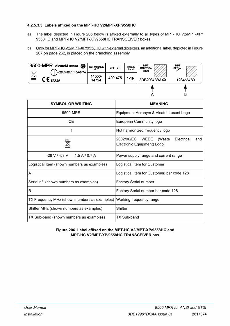
User Manual
Installation
9500 MPR for ANSI and ETSI
3DB19901DCAA Issue 01 261/374
4.2.5.3.3 Labels affixed on the MPT-HC V2/MPT-XP/9558HC
a) The label depicted in Figure 206 below is affixed externally to all types of MPT-HC V2/MPT-XP/9558HC and MPT-HC V2/MPT-XP/9558HC TRANSCEIVER boxes;
b) Only for MPT-HC V2/MPT-XP/9558HC with external diplexers, an additional label, depicted in Figure207 on page 262, is placed on the branching assembly.
Figure 206 Label affixed on the MPT-HC V2/MPT-XP/9558HC andMPT-HC V2/MPT-XP/9558HC TRANSCEIVER box
SYMBOL OR WRITING MEANING
9500-MPR Equipment Acronym & Alcatel-Lucent Logo
CE European Community logo
! Not harmonized frequency logo
2002/96/EC WEEE (Waste Electrical andElectronic Equipment) Logo
-28 V / -58 V 1,5 A / 0,7 A Power supply range and current range
Logistical Item (shown numbers as examples) Logistical Item for Customer
A Logistical Item for Customer, bar code 128
Serial n° (shown numbers as examples) Factory Serial number
B Factory Serial number bar code 128
TX Frequency MHz (shown numbers as examples) Working frequency range
Shifter MHz (shown numbers as examples) Shifter
TX Sub-band (shown numbers as examples) TX Sub-band

User Manual
Installation
9500 MPR for ANSI and ETSI
3DB19901DCAA Issue 01262/374
Figure 207 Label affixed inside the MPT-HC V2/MPT-XP/9558HC BRANCHING box
4.2.5.4 How to change polarization in the MPT-HC V2/MPT-XP/9558HC
Refer to paragraph 4.2.4.3 on page 226.
4.2.5.5 Types of pole mounting installation kits
Refer to paragraph 4.2.4.4 on page 228.
SYMBOL OR WRITING MEANING
ALU LOGO Alcatel-Lucent Logo
9500 MPR Equipment Acronym
C E European Community logo
0682 CETECOM Number
! Not Harmonized Frequency Logo
WEEE LOGO WEEE Logo
P/N / ICS 3DBXXXXXAAAA 01 Part Number + ICS
LOGISTICAL ITEM 3DBXXXXXAAXX Logistical Item
S.N. GA081528595 Serial number
A P/N + ICS Bar Code Alpha 128
B Logistical Item Bar Code Alpha 128
C Serial Number Bar Code Alpha 128
Shifter MHzTX
F min MHzF max MHz
Frequency Denomination

User Manual
Installation
9500 MPR for ANSI and ETSI
3DB19901DCAA Issue 01 263/374
4.2.5.6 Types of nose adapters
Refer to paragraph 4.2.4.5 on page 229.
4.2.5.7 1+0 MPT-HC V2/MPT-XP/9558HC installation (integrated antenna)
Refer to paragraph 4.2.4.6 on page 230.
4.2.5.8 1+0 MPT-HC V2/MPT-XP/9558HC installation (non integrated antenna)
Refer to paragraph 4.2.4.7 on page 233.
4.2.5.9 Cable connections (MPT-HC V2/MPT-XP/9558HC to MSS-1c)
4.2.5.9.1 Electrical ethernet cable
If the PFoE has been implemented; for MPT-HC V2 only one cable interconnects the MPT-HC V2 withthe MSS-1c, for MPT-XP one cable interconnects the MPT-XP with the MPT Extended Power Unit andone cable interconnects the MPT Extended Power Unit with the MSS-1c.Refer to paragraph 4.2.6.8 on page 279 for details to terminate and connect the cable to the MPT-HC V2/MPT-XP/9558HC.
4.2.5.9.2 Optical cable connection
An optical cable must be used, if the PFoE has not been implemented.
Note: First the SFP must be inserted in the MPT. The SFP is not included in the MPT.
The cable is shown in Figure 208 The cable is a preassembled cable available in different lengths (referto paragraph 4.2.9.5 on page 288).
Figure 208 LC/Q-XCO to LC fiber cord
To pull-up the cable take a cord and insert it in the slot of the cable cap. Make a knot on the cord and pull-up the cable.
Remove the cap and connect the connector to the �LC+Q-XCO� connector in the MPT-HC V2/MPT-XP/9558HC.
The overlength of the optical fiber must be rolled up in the Cable overlength box. Fix the Fiber on the poleor the tower with UV tie raps.

User Manual
Installation
9500 MPR for ANSI and ETSI
3DB19901DCAA Issue 01264/374
Figure 209 Fiber cable overlength box
4.2.5.9.3 Power supply cable connection
The power supply cable is a coaxial cable, which is used only if the optical cable is used to transport theEthernet traffic. Two types of coaxial cables are available according to the length (less than 200 m or morethan 200 m).
The coaxial cable must be connected to:
� IDU-side to the MSS-1c through the N-to-Ethernet pair Pigtail + RJ45;
� ODU-side to the N-to-Ethernet pair Pigtail (+ RJ45 + R2CT). The R2CT must be then connected tothe relevant connector on the MPT-HC V2/MPT-XP/9558HC. For the termination of the cable withRJ45 and R2CT refer to par. 4.2.6.8).
4.2.5.10 Installing the �Flextwist� waveguide (non integrated antenna)
Refer to paragraph 4.2.4.11 on page 247.
4.2.5.11 MPT-HC V2/MPT-XP/9558HC system grounding
Refer to paragraph 4.2.4.12 on page 249.
4.2.5.12 Cable grounding
Refer to paragraph 4.2.4.13 on page 249.
4.2.5.13 Type N connectors and grounding kits waterproofing on the IDU/ODU cables
Refer to paragraph 4.2.4.14 on page 250.
4.2.6 MPT-MC installation (MPR-E)
The MPT-MC installation section is divided in:

User Manual
Installation
9500 MPR for ANSI and ETSI
3DB19901DCAA Issue 01 265/374
� Types of MPT-MC (par. 4.2.6.1 on page 265)
� MPT-MC operative information (par. 4.2.6.2 on page 267)
� How to change polarization in the MPT-MC (par. 4.2.6.3 on page 272)
� Types of pole mounting installation kits (par. 4.2.6.4 on page 274)
� Types of nose adapters (par. 4.2.6.5 on page 274)
� 1+0 MPT-MC installation (integrated antenna) - all frequencies (par. 4.2.6.6 on page 274)
� 1+0 MPT-MC installation (non integrated antenna) - all frequencies (par. 4.2.6.7 on page 277)
� To terminate the ethernet cable (MPT-MC side) and to pull up it from indoor to MPT-MC (par. 4.2.6.8on page 279)
� Installing the �Flextwist� waveguide (not integrated antenna cases) (par. 4.2.6.9 on page 283)
� MPT-MC system grounding (par. 4.2.6.10 on page 283)
� Cable grounding (par. 4.2.6.11 on page 283)
4.2.6.1 Types of MPT-MC
The MPT-MC consists of one or two cabinets including the Ethernet interface + modem + RF transceiver+ branching of a channel.
Two mechanical solutions are adopted:
[1] with embedded diplexer for cost optimisation, shown in Figure 210, where the branching (diplexer)is internal to the MPT-MC cabinet; this type of MPT-MC is identified by one Logistical Item only;
[2] with external diplexer: due to an high number of shifters the diplexer is external for the flexibility ofthe shifter customization, shown in Figure 211, where MPT-MC is composed by two independentunits: the BRANCHING assembly (containing the diplexer) and the RF TRANSCEIVER assembly(containing the RF section); each of this type of MPT-MC is identified by two Logistical Items, onefor the BRANCHING assembly and another for the RF TRANSCEIVER assembly. To read theBRANCHING assembly identification label it is necessary to separate the BRANCHING assemblyfrom the RF TRANSCEIVER assembly.
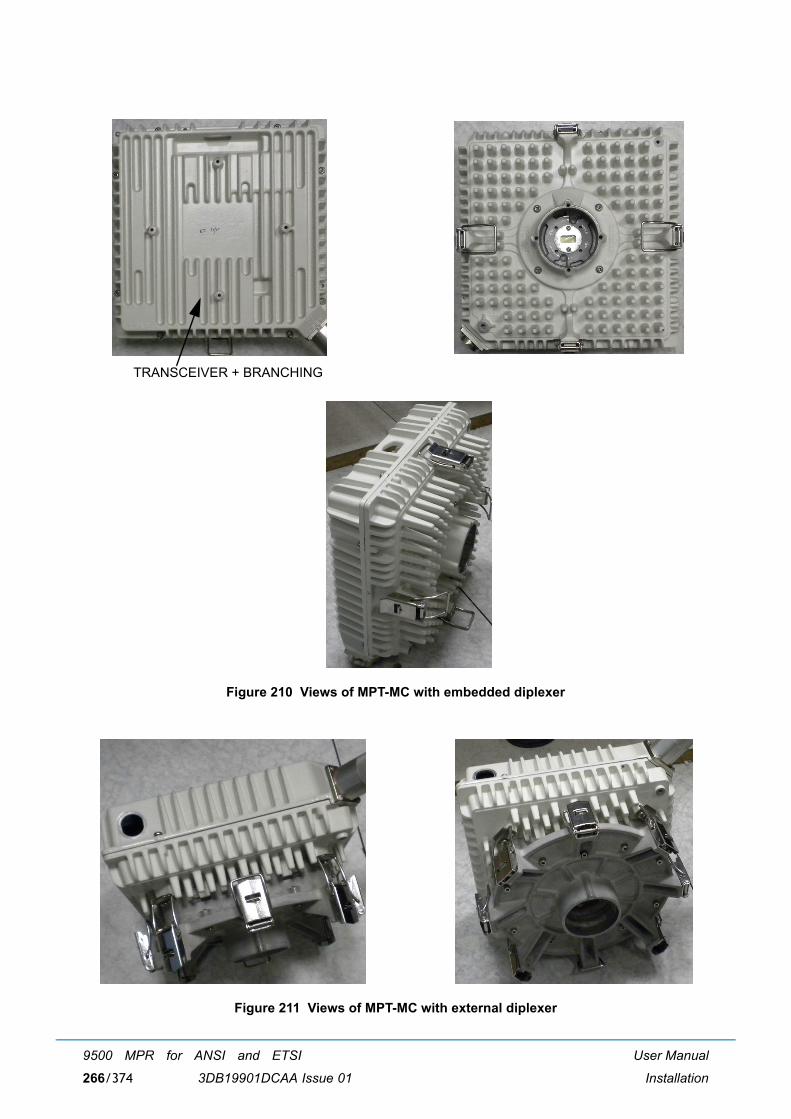
User Manual
Installation
9500 MPR for ANSI and ETSI
3DB19901DCAA Issue 01266/374
Figure 210 Views of MPT-MC with embedded diplexer
Figure 211 Views of MPT-MC with external diplexer
TRANSCEIVER + BRANCHING
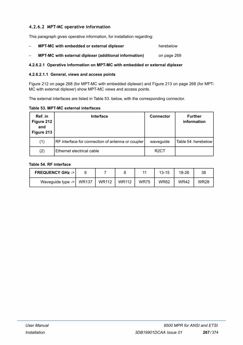
User Manual
Installation
9500 MPR for ANSI and ETSI
3DB19901DCAA Issue 01 267/374
4.2.6.2 MPT-MC operative information
This paragraph gives operative information, for installation regarding:
� MPT-MC with embedded or external diplexer herebelow
� MPT-MC with external diplexer (additional information) on page 269
4.2.6.2.1 Operative information on MPT-MC with embedded or external diplexer
4.2.6.2.1.1 General, views and access points
Figure 212 on page 268 (for MPT-MC with embedded diplexer) and Figure 213 on page 268 (for MPT-MC with external diplexer) show MPT-MC views and access points.
The external interfaces are listed in Table 53. below, with the corresponding connector.
Table 53. MPT-MC external interfaces
Table 54. RF interface
Ref. in Figure 212
and Figure 213
Interface Connector Further information
(1) RF interface for connection of antenna or coupler waveguide Table 54. herebelow
(2) Ethernet electrical cable R2CT
FREQUENCY GHz -> 6 7 8 11 13-15 18-26 38
Waveguide type -> WR137 WR112 WR112 WR75 WR62 WR42 WR28
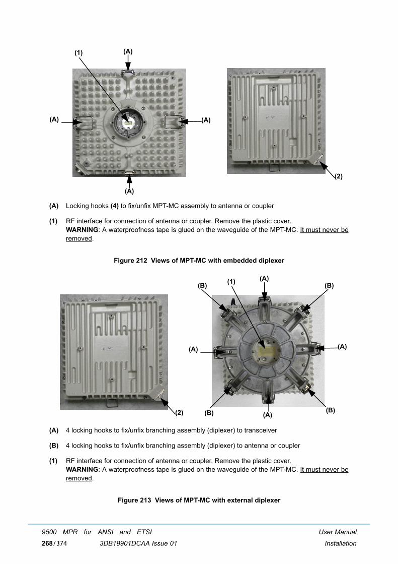
User Manual
Installation
9500 MPR for ANSI and ETSI
3DB19901DCAA Issue 01268/374
Figure 212 Views of MPT-MC with embedded diplexer
Figure 213 Views of MPT-MC with external diplexer
(A) Locking hooks (4) to fix/unfix MPT-MC assembly to antenna or coupler
(1) RF interface for connection of antenna or coupler. Remove the plastic cover.WARNING: A waterproofness tape is glued on the waveguide of the MPT-MC. It must never beremoved.
(A) 4 locking hooks to fix/unfix branching assembly (diplexer) to transceiver
(B) 4 locking hooks to fix/unfix branching assembly (diplexer) to antenna or coupler
(1) RF interface for connection of antenna or coupler. Remove the plastic cover.WARNING: A waterproofness tape is glued on the waveguide of the MPT-MC. It must never beremoved.
(1) (A)
(A)(A)
(A)
(2)
(1) (A)
(A)(A)
(A)
(B)(B)
(B)(B)(2)
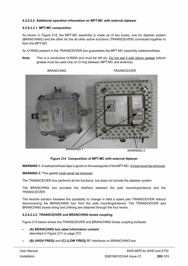
User Manual
Installation
9500 MPR for ANSI and ETSI
3DB19901DCAA Issue 01 269/374
4.2.6.2.2 Additional operative information on MPT-MC with external diplexer
4.2.6.2.2.1 MPT-MC composition
As shown in Figure 214, the MPT-MC assembly is made up of two boxes, one for diplexer system(BRANCHING) and the other for the all other active functions (TRANSCEIVER) connected together toform the MPT-MC.
An O-RING present in the TRANSCEIVER box guarantees the MPT-MC assembly waterproofness.
Note: This is a conductive O-RING and must be left dry. Do not wet it with silicon grease (silicongrease must be used only on O-ring between MPT-MC and antenna).
Figure 214 Composition of MPT-MC with external diplexer
WARNING 1: A waterproofness tape is glued on the waveguide of the MPT-MC. It must never be removed.
WARNING 2: This gasket must never be removed.
The TRANSCEIVER box performs all the functions, but does not include the diplexer system.
The BRANCHING box provides the interface between the pole mounting/antenna and theTRANSCEIVER.
The favorite solution foresees the possibility to change in field a spare part TRANSCEIVER withoutdisconnecting the BRANCHING box from the pole mounting/antenna. The TRANSCEIVER andBRANCHING boxes fixing and unfixing are obtained through the four levers.
4.2.6.2.2.2 TRANSCEIVER and BRANCHING boxes coupling
Figure 215 below shows the TRANSCEIVER and BRANCHING boxes coupling surfaces:
� (A) BRANCHING box label informative contentdescribed in Figure 217 on page 272
� (B) (HIGH FREQ) and (C) (LOW FREQ) RF interfaces on BRANCHING box
BRANCHING TRANSCEIVER
WARNING 1 WARNING 2
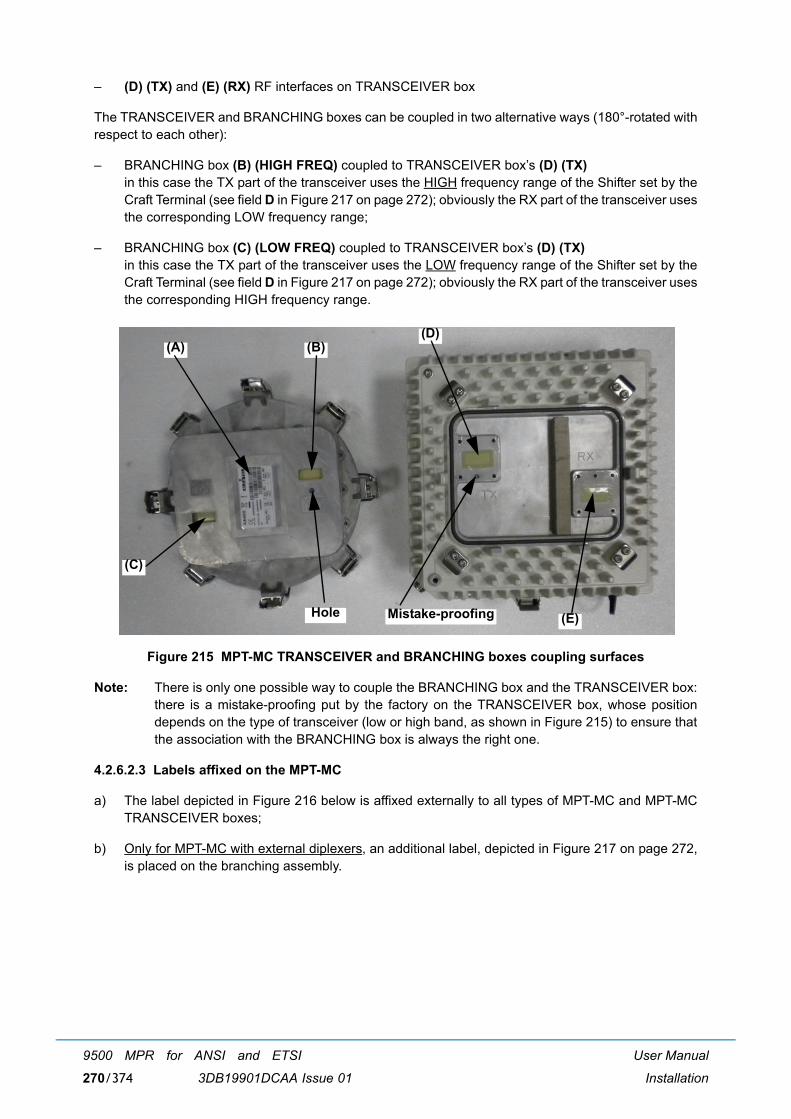
User Manual
Installation
9500 MPR for ANSI and ETSI
3DB19901DCAA Issue 01270/374
� (D) (TX) and (E) (RX) RF interfaces on TRANSCEIVER box
The TRANSCEIVER and BRANCHING boxes can be coupled in two alternative ways (180°-rotated withrespect to each other):
� BRANCHING box (B) (HIGH FREQ) coupled to TRANSCEIVER box�s (D) (TX)in this case the TX part of the transceiver uses the HIGH frequency range of the Shifter set by theCraft Terminal (see field D in Figure 217 on page 272); obviously the RX part of the transceiver usesthe corresponding LOW frequency range;
� BRANCHING box (C) (LOW FREQ) coupled to TRANSCEIVER box�s (D) (TX)in this case the TX part of the transceiver uses the LOW frequency range of the Shifter set by theCraft Terminal (see field D in Figure 217 on page 272); obviously the RX part of the transceiver usesthe corresponding HIGH frequency range.
Figure 215 MPT-MC TRANSCEIVER and BRANCHING boxes coupling surfaces
Note: There is only one possible way to couple the BRANCHING box and the TRANSCEIVER box:there is a mistake-proofing put by the factory on the TRANSCEIVER box, whose positiondepends on the type of transceiver (low or high band, as shown in Figure 215) to ensure thatthe association with the BRANCHING box is always the right one.
4.2.6.2.3 Labels affixed on the MPT-MC
a) The label depicted in Figure 216 below is affixed externally to all types of MPT-MC and MPT-MCTRANSCEIVER boxes;
b) Only for MPT-MC with external diplexers, an additional label, depicted in Figure 217 on page 272,is placed on the branching assembly.
(A) (B)
(C)
(D)
(E)Mistake-proofingHole
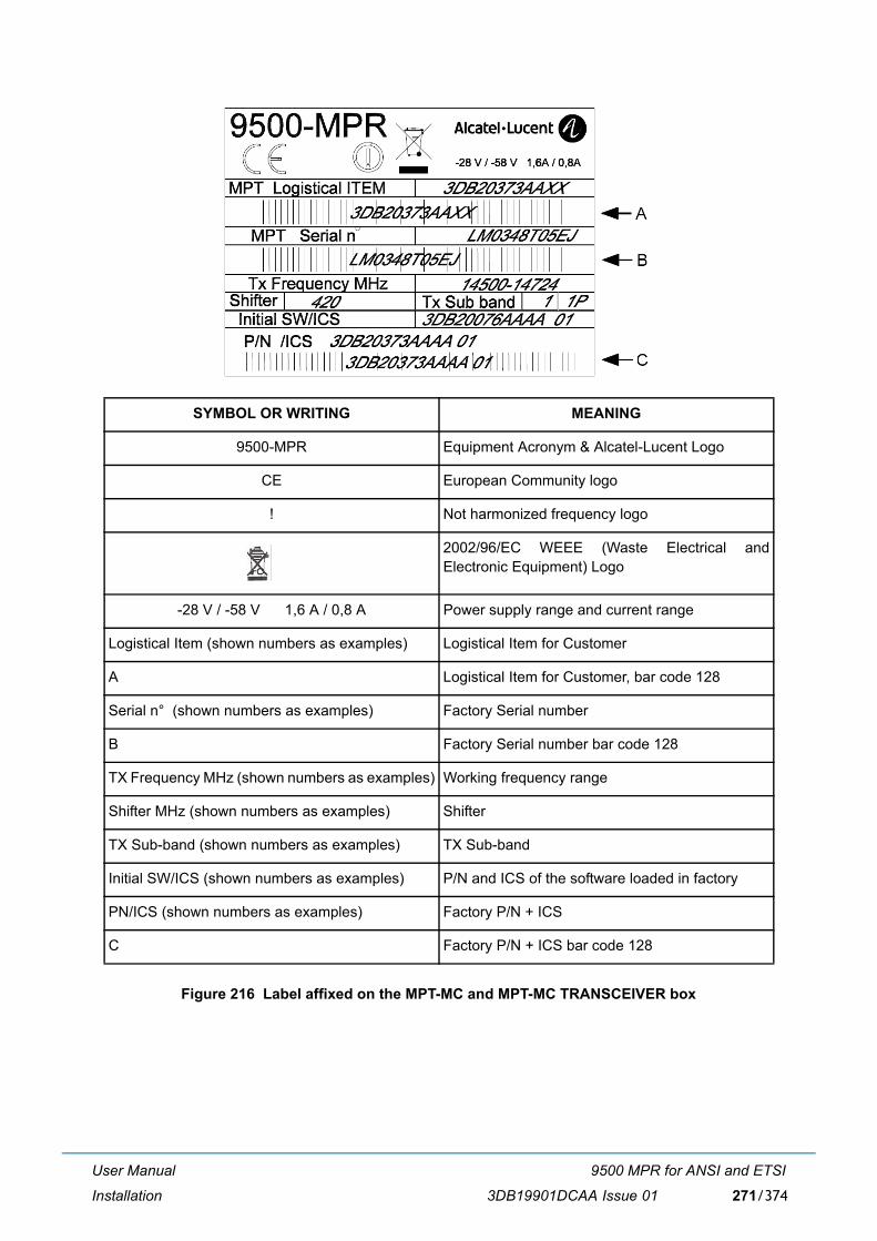
User Manual
Installation
9500 MPR for ANSI and ETSI
3DB19901DCAA Issue 01 271/374
Figure 216 Label affixed on the MPT-MC and MPT-MC TRANSCEIVER box
SYMBOL OR WRITING MEANING
9500-MPR Equipment Acronym & Alcatel-Lucent Logo
CE European Community logo
! Not harmonized frequency logo
2002/96/EC WEEE (Waste Electrical andElectronic Equipment) Logo
-28 V / -58 V 1,6 A / 0,8 A Power supply range and current range
Logistical Item (shown numbers as examples) Logistical Item for Customer
A Logistical Item for Customer, bar code 128
Serial n° (shown numbers as examples) Factory Serial number
B Factory Serial number bar code 128
TX Frequency MHz (shown numbers as examples) Working frequency range
Shifter MHz (shown numbers as examples) Shifter
TX Sub-band (shown numbers as examples) TX Sub-band
Initial SW/ICS (shown numbers as examples) P/N and ICS of the software loaded in factory
PN/ICS (shown numbers as examples) Factory P/N + ICS
C Factory P/N + ICS bar code 128
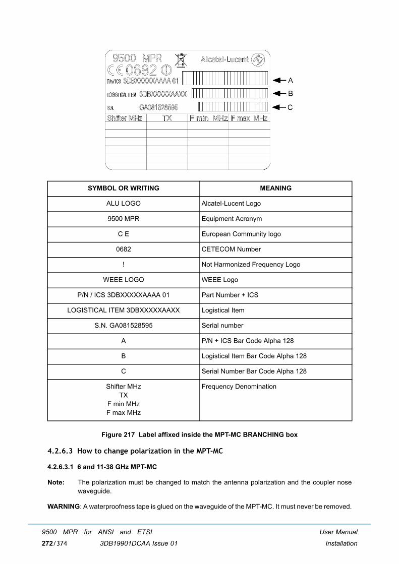
User Manual
Installation
9500 MPR for ANSI and ETSI
3DB19901DCAA Issue 01272/374
Figure 217 Label affixed inside the MPT-MC BRANCHING box
4.2.6.3 How to change polarization in the MPT-MC
4.2.6.3.1 6 and 11-38 GHz MPT-MC
Note: The polarization must be changed to match the antenna polarization and the coupler nosewaveguide.
WARNING: A waterproofness tape is glued on the waveguide of the MPT-MC. It must never be removed.
SYMBOL OR WRITING MEANING
ALU LOGO Alcatel-Lucent Logo
9500 MPR Equipment Acronym
C E European Community logo
0682 CETECOM Number
! Not Harmonized Frequency Logo
WEEE LOGO WEEE Logo
P/N / ICS 3DBXXXXXAAAA 01 Part Number + ICS
LOGISTICAL ITEM 3DBXXXXXAAXX Logistical Item
S.N. GA081528595 Serial number
A P/N + ICS Bar Code Alpha 128
B Logistical Item Bar Code Alpha 128
C Serial Number Bar Code Alpha 128
Shifter MHzTX
F min MHzF max MHz
Frequency Denomination
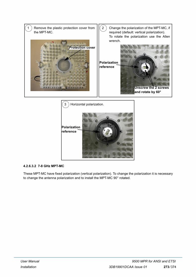
User Manual
Installation
9500 MPR for ANSI and ETSI
3DB19901DCAA Issue 01 273/374
4.2.6.3.2 7-8 GHz MPT-MC
These MPT-MC have fixed polarization (vertical polarization). To change the polarization it is necessaryto change the antenna polarization and to install the MPT-MC 90° rotated.
1 2
3
Remove the plastic protection cover fromthe MPT-MC.
Change the polarization of the MPT-MC, ifrequired (default: vertical polarization).To rotate the polarization use the Allenwrench.
Horizontal polarization.
Protection cover
Unscrew the 2 screwsand rotate by 60°
Polarizationreference
Polarizationreference
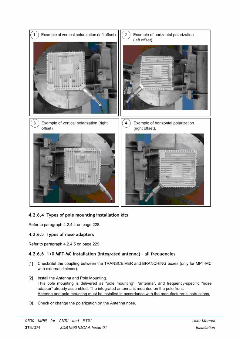
User Manual
Installation
9500 MPR for ANSI and ETSI
3DB19901DCAA Issue 01274/374
4.2.6.4 Types of pole mounting installation kits
Refer to paragraph 4.2.4.4 on page 228.
4.2.6.5 Types of nose adapters
Refer to paragraph 4.2.4.5 on page 229.
4.2.6.6 1+0 MPT-MC installation (integrated antenna) - all frequencies
[1] Check/Set the coupling between the TRANSCEIVER and BRANCHING boxes (only for MPT-MCwith external diplexer).
[2] Install the Antenna and Pole Mounting.This pole mounting is delivered as �pole mounting�, �antenna�, and frequency-specific �noseadapter� already assembled. The integrated antenna is mounted on the pole front.Antenna and pole mounting must be installed in accordance with the manufacturer�s instructions.
[3] Check or change the polarization on the Antenna nose.
1 2Example of vertical polarization (left offset). Example of horizontal polarization (left offset).
3 4Example of vertical polarization (rightoffset).
Example of horizontal polarization (right offset).
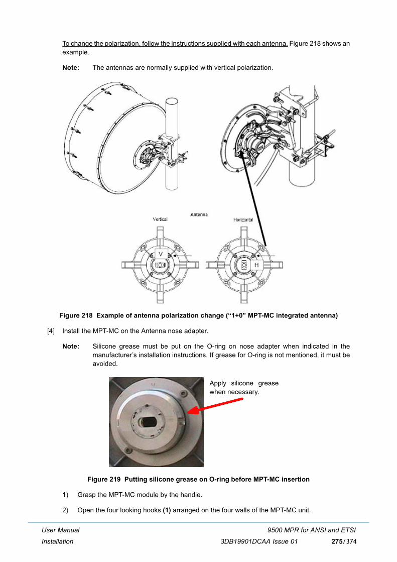
User Manual
Installation
9500 MPR for ANSI and ETSI
3DB19901DCAA Issue 01 275/374
To change the polarization, follow the instructions supplied with each antenna. Figure 218 shows anexample.
Note: The antennas are normally supplied with vertical polarization.
Figure 218 Example of antenna polarization change (�1+0� MPT-MC integrated antenna)
[4] Install the MPT-MC on the Antenna nose adapter.
Note: Silicone grease must be put on the O-ring on nose adapter when indicated in themanufacturer�s installation instructions. If grease for O-ring is not mentioned, it must beavoided.
Figure 219 Putting silicone grease on O-ring before MPT-MC insertion
1) Grasp the MPT-MC module by the handle.
2) Open the four looking hooks (1) arranged on the four walls of the MPT-MC unit.
Apply silicone greasewhen necessary.
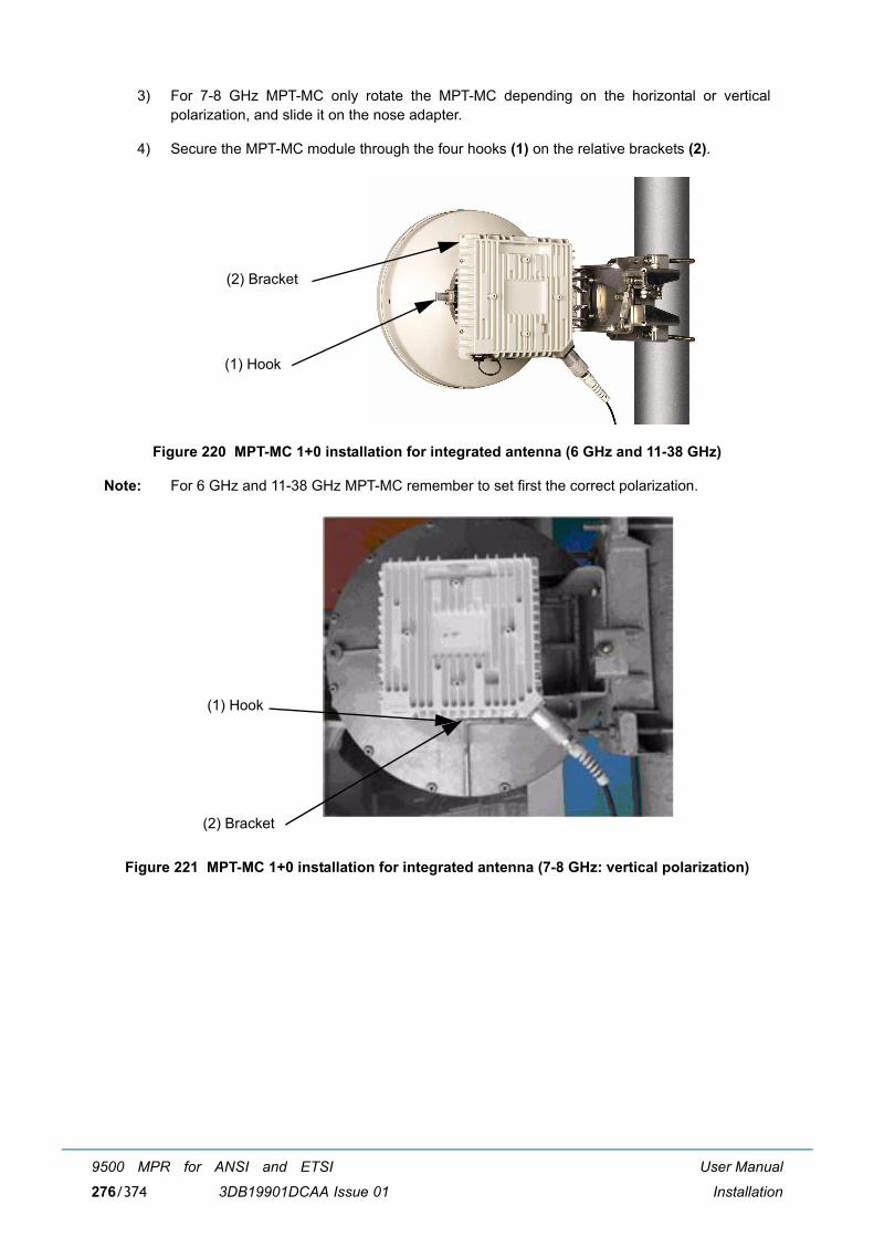
User Manual
Installation
9500 MPR for ANSI and ETSI
3DB19901DCAA Issue 01276/374
3) For 7-8 GHz MPT-MC only rotate the MPT-MC depending on the horizontal or verticalpolarization, and slide it on the nose adapter.
4) Secure the MPT-MC module through the four hooks (1) on the relative brackets (2).
Figure 220 MPT-MC 1+0 installation for integrated antenna (6 GHz and 11-38 GHz)
Note: For 6 GHz and 11-38 GHz MPT-MC remember to set first the correct polarization.
Figure 221 MPT-MC 1+0 installation for integrated antenna (7-8 GHz: vertical polarization)
(1) Hook
(2) Bracket
(1) Hook
(2) Bracket
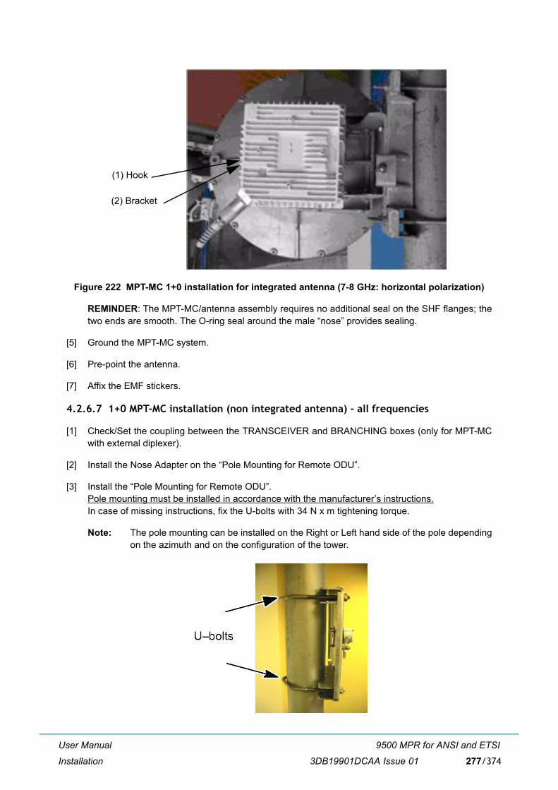
User Manual
Installation
9500 MPR for ANSI and ETSI
3DB19901DCAA Issue 01 277/374
Figure 222 MPT-MC 1+0 installation for integrated antenna (7-8 GHz: horizontal polarization)
REMINDER: The MPT-MC/antenna assembly requires no additional seal on the SHF flanges; thetwo ends are smooth. The O-ring seal around the male �nose� provides sealing.
[5] Ground the MPT-MC system.
[6] Pre-point the antenna.
[7] Affix the EMF stickers.
4.2.6.7 1+0 MPT-MC installation (non integrated antenna) - all frequencies
[1] Check/Set the coupling between the TRANSCEIVER and BRANCHING boxes (only for MPT-MCwith external diplexer).
[2] Install the Nose Adapter on the �Pole Mounting for Remote ODU�.
[3] Install the �Pole Mounting for Remote ODU�.Pole mounting must be installed in accordance with the manufacturer�s instructions.In case of missing instructions, fix the U-bolts with 34 N x m tightening torque.
Note: The pole mounting can be installed on the Right or Left hand side of the pole dependingon the azimuth and on the configuration of the tower.
(1) Hook
(2) Bracket
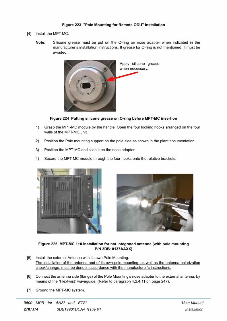
User Manual
Installation
9500 MPR for ANSI and ETSI
3DB19901DCAA Issue 01278/374
Figure 223 "Pole Mounting for Remote ODU" installation
[4] Install the MPT-MC.
Note: Silicone grease must be put on the O-ring on nose adapter when indicated in themanufacturer�s installation instructions. If grease for O-ring is not mentioned, it must beavoided.
Figure 224 Putting silicone grease on O-ring before MPT-MC insertion
1) Grasp the MPT-MC module by the handle. Open the four looking hooks arranged on the fourwalls of the MPT-MC unit.
2) Position the Pole mounting support on the pole side as shown in the plant documentation.
3) Position the MPT-MC and slide it on the nose adapter.
4) Secure the MPT-MC module through the four hooks onto the relative brackets.
Figure 225 MPT-MC 1+0 installation for not integrated antenna (with pole mounting P/N 3DB10137AAXX)
[5] Install the external Antenna with its own Pole Mounting.The installation of the antenna and of its own pole mounting, as well as the antenna polarizationcheck/change, must be done in accordance with the manufacturer�s instructions.
[6] Connect the antenna side (flange) of the Pole Mounting�s nose adapter to the external antenna, bymeans of the �Flextwist� waveguide. (Refer to paragraph 4.2.4.11 on page 247).
[7] Ground the MPT-MC system.
Apply silicone greasewhen necessary.
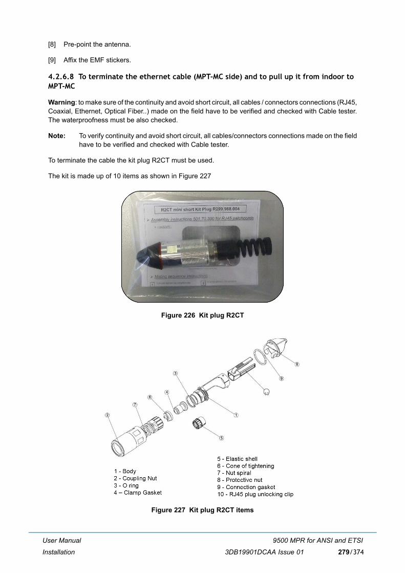
User Manual
Installation
9500 MPR for ANSI and ETSI
3DB19901DCAA Issue 01 279/374
[8] Pre-point the antenna.
[9] Affix the EMF stickers.
4.2.6.8 To terminate the ethernet cable (MPT-MC side) and to pull up it from indoor to MPT-MC
Warning: to make sure of the continuity and avoid short circuit, all cables / connectors connections (RJ45,Coaxial, Ethernet, Optical Fiber..) made on the field have to be verified and checked with Cable tester.The waterproofness must be also checked.
Note: To verify continuity and avoid short circuit, all cables/connectors connections made on the fieldhave to be verified and checked with Cable tester.
To terminate the cable the kit plug R2CT must be used.
The kit is made up of 10 items as shown in Figure 227
Figure 226 Kit plug R2CT
Figure 227 Kit plug R2CT items
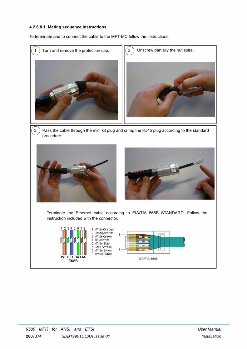
User Manual
Installation
9500 MPR for ANSI and ETSI
3DB19901DCAA Issue 01280/374
4.2.6.8.1 Mating sequence instructions
To terminate and to connect the cable to the MPT-MC follow the instructions:
1 2Turn and remove the protection cap. Unscrew partially the nut spiral.
3 Pass the cable through the mini kit plug and crimp the RJ45 plug according to the standardprocedure
Terminate the Ethernet cable according to EIA/TIA 568B STANDARD. Follow theinstruction included with the connector.
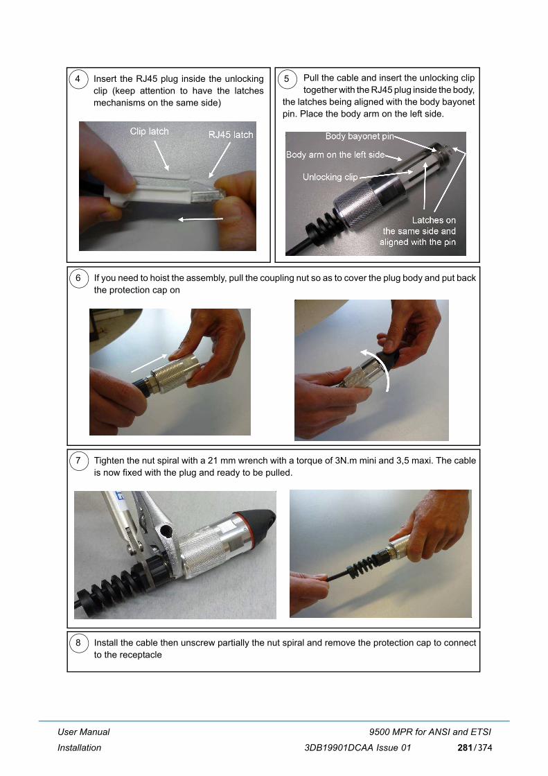
User Manual
Installation
9500 MPR for ANSI and ETSI
3DB19901DCAA Issue 01 281/374
6 If you need to hoist the assembly, pull the coupling nut so as to cover the plug body and put backthe protection cap on
7 Tighten the nut spiral with a 21 mm wrench with a torque of 3N.m mini and 3,5 maxi. The cableis now fixed with the plug and ready to be pulled.
8 Install the cable then unscrew partially the nut spiral and remove the protection cap to connectto the receptacle
4 5Insert the RJ45 plug inside the unlockingclip (keep attention to have the latchesmechanisms on the same side)
Pull the cable and insert the unlocking cliptogether with the RJ45 plug inside the body,
the latches being aligned with the body bayonetpin. Place the body arm on the left side.
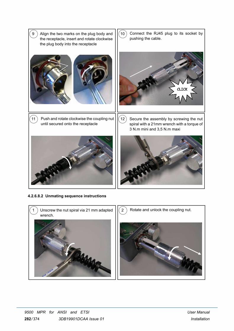
User Manual
Installation
9500 MPR for ANSI and ETSI
3DB19901DCAA Issue 01282/374
4.2.6.8.2 Unmating sequence instructions
11 Secure the assembly by screwing the nutspiral with a 21mm wrench with a torque of3 N.m mini and 3,5 N.m maxi
12Push and rotate clockwise the coupling nutuntil secured onto the receptacle
9 10Align the two marks on the plug body andthe receptacle, insert and rotate clockwisethe plug body into the receptacle
Connect the RJ45 plug to its socket bypushing the cable.
1 2Unscrew the nut spiral via 21 mm adaptedwrench.
Rotate and unlock the coupling nut.
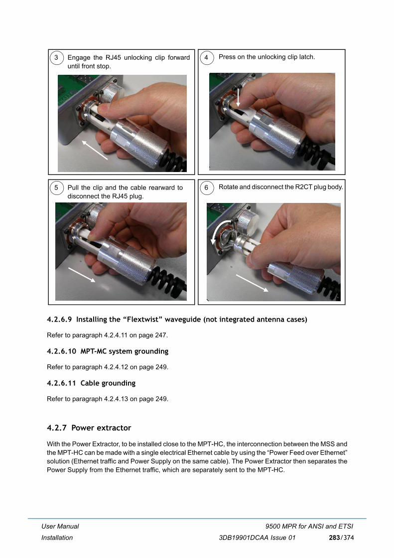
User Manual
Installation
9500 MPR for ANSI and ETSI
3DB19901DCAA Issue 01 283/374
4.2.6.9 Installing the �Flextwist� waveguide (not integrated antenna cases)
Refer to paragraph 4.2.4.11 on page 247.
4.2.6.10 MPT-MC system grounding
Refer to paragraph 4.2.4.12 on page 249.
4.2.6.11 Cable grounding
Refer to paragraph 4.2.4.13 on page 249.
4.2.7 Power extractor
With the Power Extractor, to be installed close to the MPT-HC, the interconnection between the MSS andthe MPT-HC can be made with a single electrical Ethernet cable by using the �Power Feed over Ethernet�solution (Ethernet traffic and Power Supply on the same cable). The Power Extractor then separates thePower Supply from the Ethernet traffic, which are separately sent to the MPT-HC.
5 6Pull the clip and the cable rearward todisconnect the RJ45 plug.
Rotate and disconnect the R2CT plug body.
3 Engage the RJ45 unlocking clip forwarduntil front stop.
Press on the unlocking clip latch.4
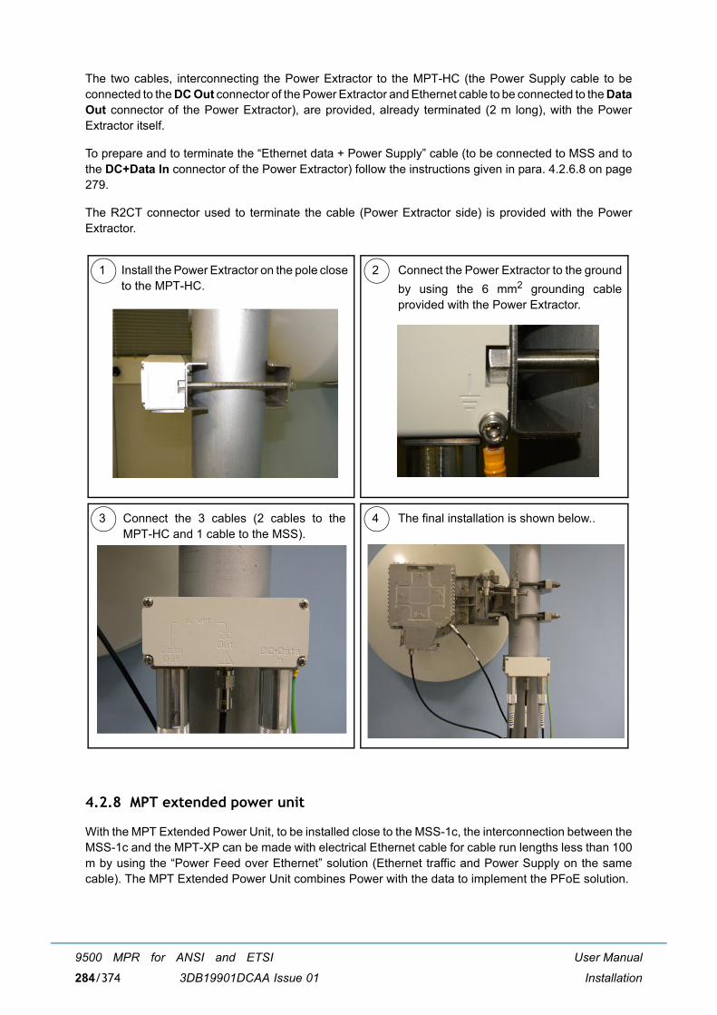
User Manual
Installation
9500 MPR for ANSI and ETSI
3DB19901DCAA Issue 01284/374
The two cables, interconnecting the Power Extractor to the MPT-HC (the Power Supply cable to beconnected to the DC Out connector of the Power Extractor and Ethernet cable to be connected to the DataOut connector of the Power Extractor), are provided, already terminated (2 m long), with the PowerExtractor itself.
To prepare and to terminate the �Ethernet data + Power Supply� cable (to be connected to MSS and tothe DC+Data In connector of the Power Extractor) follow the instructions given in para. 4.2.6.8 on page279.
The R2CT connector used to terminate the cable (Power Extractor side) is provided with the PowerExtractor.
4.2.8 MPT extended power unit
With the MPT Extended Power Unit, to be installed close to the MSS-1c, the interconnection between theMSS-1c and the MPT-XP can be made with electrical Ethernet cable for cable run lengths less than 100m by using the �Power Feed over Ethernet� solution (Ethernet traffic and Power Supply on the samecable). The MPT Extended Power Unit combines Power with the data to implement the PFoE solution.
3 4Connect the 3 cables (2 cables to theMPT-HC and 1 cable to the MSS).
The final installation is shown below..
1 Install the Power Extractor on the pole closeto the MPT-HC.
Connect the Power Extractor to the groundby using the 6 mm2 grounding cableprovided with the Power Extractor.
2

User Manual
Installation
9500 MPR for ANSI and ETSI
3DB19901DCAA Issue 01 285/374
One cable, interconnects the MPT Extended Power Unit with the MPT-XP (the PFoE cable to beconnected to the DC+ODU Data connector of the MPT Extended Power Unit and Ethernet cable to beconnected to the DC+Data connector of the MPT-XP). A second cable interconnects the MPT ExtendedPower Unit IDU Data connector with the MSS-1c electrical Ethernet connector.
To prepare and to terminate the �Ethernet data + Power Supply� cable (to be connected to MPT ExtendedPower Unit and to the DC+Data connector of the MPT-XP) follow the instructions given in para. 4.2.6.8on page 279.
The R2CT connector used to terminate the cable (MPT-XP side) must be provided.
When optical cable is used to transport the Ethernet traffic to the MPT-XP, the MPT Extended Power Unitprovides power to the MPT-XP using coax cable connected to the Type N DC connector on the MPTExtended Power Unit.
Coax cable, interconnects the MPT Extended Power Unit with the MPT-XP (the coax cable to beconnected to the DC connector of the MPT Extended Power Unit. An adapter cable converts coax to RJ-45 to be connected to the DC+Data connector of the MPT-XP).
To prepare and to terminate the �coax Power Supply� cable (to be connected to MPT Extended Power Unitand to the DC+Data connector of the MPT-XP) follow the instructions given in para. 4.2.6.8 on page 279.
The R2CT connector used to terminate the cable (MPT-XP side) must be provided.
4.2.9 MPR-E indoor installation
This section includes:
� Indoor accessories (par. 4.2.9.1 on page 285)
� Indoor cables (par. 4.2.9.2 on page 286)
� Indoor accessories for MPT-HC/MPT-HC V2/MPT-XP (par. 4.2.9.3 on page 287)
� Accessories and cables for MPT-HC connections (par. 4.2.9.4 on page 287)
� Accessories and cables for MPT-HC V2/MPT-XP/9558HC connections (par. 4.2.9.5 on page 288)
� Accessories and cables for MPT-MC connections (par. 4.2.9.6 on page 290)
� Nose adapter for MPT-HC/MPT-HC V2/MPT-MC and MPT-XP (par. 4.2.9.7 on page 291)
� Flextwists and N cable for MPT-HC/MPT-HC V2/MPT-MC, MPT-XP, and 9558HC (par. 4.2.9.8 onpage 291)
� Ethernet electrical cables (par. 4.2.9.9 on page 292)
� Ethernet optical cables (par. 4.2.9.10 on page 292)
� E1/T1 connectors on the front panel of the MSS-1c (par. 4.2.9.11 on page 293)
4.2.9.1 Indoor accessories
3CC50042AAAA ETSI Rack mounting kit (valid for TRU 1AD137820001, TRU 1AD137830001,support 19" module 120 ohm 3CC07810AAAA)
3CC07810AAAA Distributor subrack for 120 ohm EMC (Panel 3U)
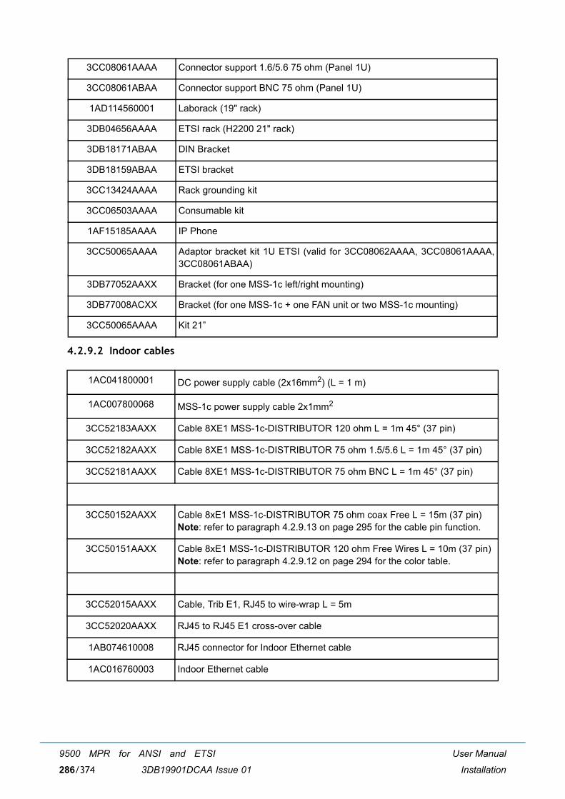
User Manual
Installation
9500 MPR for ANSI and ETSI
3DB19901DCAA Issue 01286/374
4.2.9.2 Indoor cables
3CC08061AAAA Connector support 1.6/5.6 75 ohm (Panel 1U)
3CC08061ABAA Connector support BNC 75 ohm (Panel 1U)
1AD114560001 Laborack (19" rack)
3DB04656AAAA ETSI rack (H2200 21" rack)
3DB18171ABAA DIN Bracket
3DB18159ABAA ETSI bracket
3CC13424AAAA Rack grounding kit
3CC06503AAAA Consumable kit
1AF15185AAAA IP Phone
3CC50065AAAA Adaptor bracket kit 1U ETSI (valid for 3CC08062AAAA, 3CC08061AAAA,3CC08061ABAA)
3DB77052AAXX Bracket (for one MSS-1c left/right mounting)
3DB77008ACXX Bracket (for one MSS-1c + one FAN unit or two MSS-1c mounting)
3CC50065AAAA Kit 21�
1AC041800001 DC power supply cable (2x16mm2) (L = 1 m)
1AC007800068 MSS-1c power supply cable 2x1mm2
3CC52183AAXX Cable 8XE1 MSS-1c-DISTRIBUTOR 120 ohm L = 1m 45° (37 pin)
3CC52182AAXX Cable 8XE1 MSS-1c-DISTRIBUTOR 75 ohm 1.5/5.6 L = 1m 45° (37 pin)
3CC52181AAXX Cable 8XE1 MSS-1c-DISTRIBUTOR 75 ohm BNC L = 1m 45° (37 pin)
3CC50152AAXX Cable 8xE1 MSS-1c-DISTRIBUTOR 75 ohm coax Free L = 15m (37 pin)Note: refer to paragraph 4.2.9.13 on page 295 for the cable pin function.
3CC50151AAXX Cable 8xE1 MSS-1c-DISTRIBUTOR 120 ohm Free Wires L = 10m (37 pin)Note: refer to paragraph 4.2.9.12 on page 294 for the color table.
3CC52015AAXX Cable, Trib E1, RJ45 to wire-wrap L = 5m
3CC52020AAXX RJ45 to RJ45 E1 cross-over cable
1AB074610008 RJ45 connector for Indoor Ethernet cable
1AC016760003 Indoor Ethernet cable
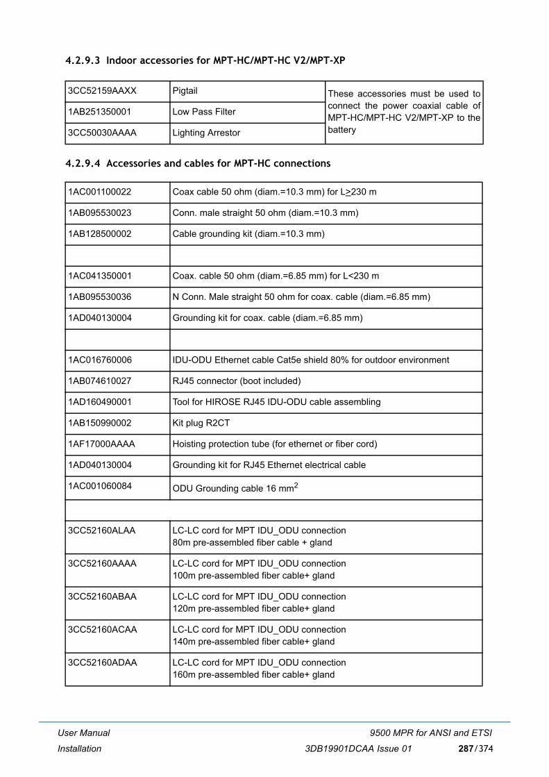
User Manual
Installation
9500 MPR for ANSI and ETSI
3DB19901DCAA Issue 01 287/374
4.2.9.3 Indoor accessories for MPT-HC/MPT-HC V2/MPT-XP
4.2.9.4 Accessories and cables for MPT-HC connections
3CC52159AAXX Pigtail These accessories must be used toconnect the power coaxial cable ofMPT-HC/MPT-HC V2/MPT-XP to thebattery
1AB251350001 Low Pass Filter
3CC50030AAAA Lighting Arrestor
1AC001100022 Coax cable 50 ohm (diam.=10.3 mm) for L>230 m
1AB095530023 Conn. male straight 50 ohm (diam.=10.3 mm)
1AB128500002 Cable grounding kit (diam.=10.3 mm)
1AC041350001 Coax. cable 50 ohm (diam.=6.85 mm) for L<230 m
1AB095530036 N Conn. Male straight 50 ohm for coax. cable (diam.=6.85 mm)
1AD040130004 Grounding kit for coax. cable (diam.=6.85 mm)
1AC016760006 IDU-ODU Ethernet cable Cat5e shield 80% for outdoor environment
1AB074610027 RJ45 connector (boot included)
1AD160490001 Tool for HIROSE RJ45 IDU-ODU cable assembling
1AB150990002 Kit plug R2CT
1AF17000AAAA Hoisting protection tube (for ethernet or fiber cord)
1AD040130004 Grounding kit for RJ45 Ethernet electrical cable
1AC001060084 ODU Grounding cable 16 mm2
3CC52160ALAA LC-LC cord for MPT IDU_ODU connection80m pre-assembled fiber cable + gland
3CC52160AAAA LC-LC cord for MPT IDU_ODU connection100m pre-assembled fiber cable+ gland
3CC52160ABAA LC-LC cord for MPT IDU_ODU connection120m pre-assembled fiber cable+ gland
3CC52160ACAA LC-LC cord for MPT IDU_ODU connection140m pre-assembled fiber cable+ gland
3CC52160ADAA LC-LC cord for MPT IDU_ODU connection160m pre-assembled fiber cable+ gland
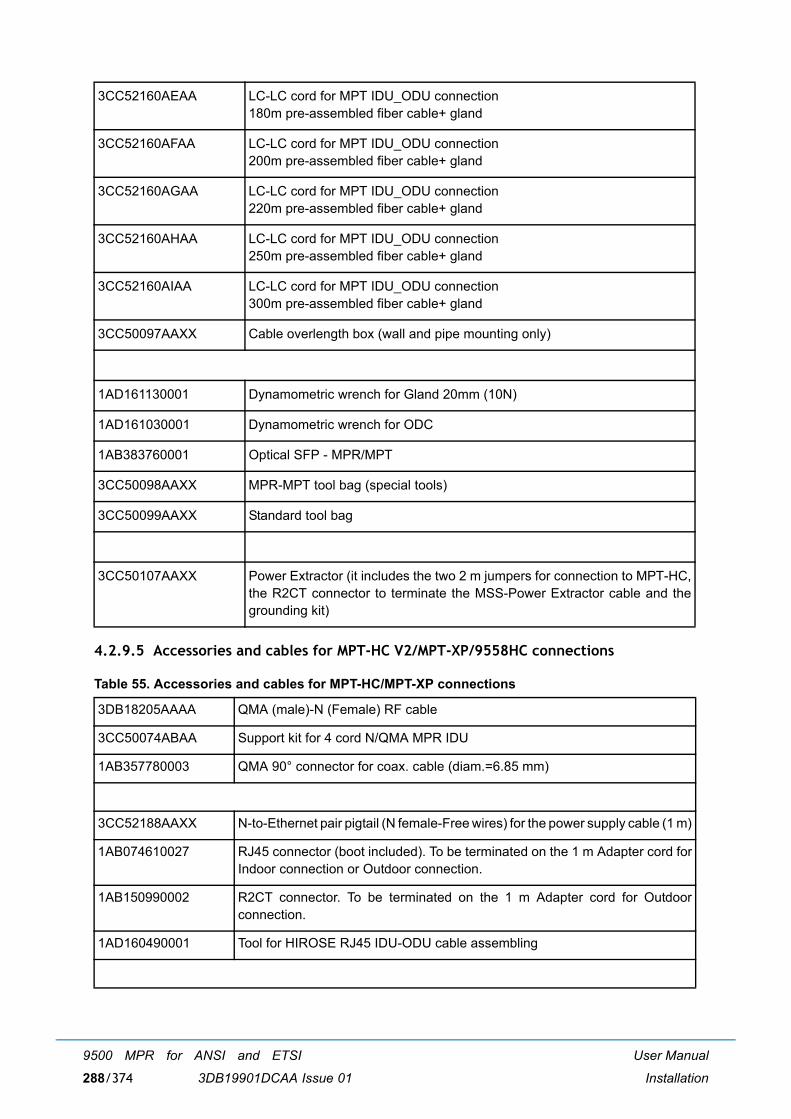
User Manual
Installation
9500 MPR for ANSI and ETSI
3DB19901DCAA Issue 01288/374
4.2.9.5 Accessories and cables for MPT-HC V2/MPT-XP/9558HC connections
Table 55. Accessories and cables for MPT-HC/MPT-XP connections
3CC52160AEAA LC-LC cord for MPT IDU_ODU connection180m pre-assembled fiber cable+ gland
3CC52160AFAA LC-LC cord for MPT IDU_ODU connection200m pre-assembled fiber cable+ gland
3CC52160AGAA LC-LC cord for MPT IDU_ODU connection220m pre-assembled fiber cable+ gland
3CC52160AHAA LC-LC cord for MPT IDU_ODU connection250m pre-assembled fiber cable+ gland
3CC52160AIAA LC-LC cord for MPT IDU_ODU connection300m pre-assembled fiber cable+ gland
3CC50097AAXX Cable overlength box (wall and pipe mounting only)
1AD161130001 Dynamometric wrench for Gland 20mm (10N)
1AD161030001 Dynamometric wrench for ODC
1AB383760001 Optical SFP - MPR/MPT
3CC50098AAXX MPR-MPT tool bag (special tools)
3CC50099AAXX Standard tool bag
3CC50107AAXX Power Extractor (it includes the two 2 m jumpers for connection to MPT-HC,the R2CT connector to terminate the MSS-Power Extractor cable and thegrounding kit)
3DB18205AAAA QMA (male)-N (Female) RF cable
3CC50074ABAA Support kit for 4 cord N/QMA MPR IDU
1AB357780003 QMA 90° connector for coax. cable (diam.=6.85 mm)
3CC52188AAXX N-to-Ethernet pair pigtail (N female-Free wires) for the power supply cable (1 m)
1AB074610027 RJ45 connector (boot included). To be terminated on the 1 m Adapter cord forIndoor connection or Outdoor connection.
1AB150990002 R2CT connector. To be terminated on the 1 m Adapter cord for Outdoorconnection.
1AD160490001 Tool for HIROSE RJ45 IDU-ODU cable assembling
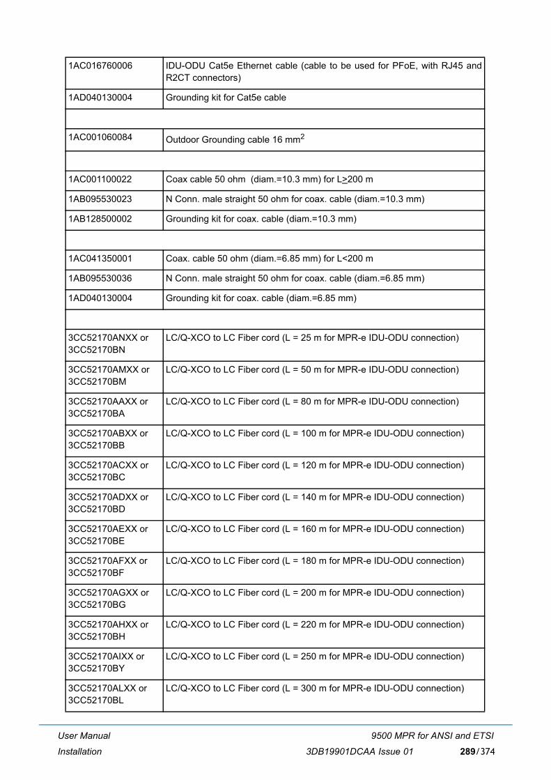
User Manual
Installation
9500 MPR for ANSI and ETSI
3DB19901DCAA Issue 01 289/374
1AC016760006 IDU-ODU Cat5e Ethernet cable (cable to be used for PFoE, with RJ45 andR2CT connectors)
1AD040130004 Grounding kit for Cat5e cable
1AC001060084 Outdoor Grounding cable 16 mm2
1AC001100022 Coax cable 50 ohm (diam.=10.3 mm) for L>200 m
1AB095530023 N Conn. male straight 50 ohm for coax. cable (diam.=10.3 mm)
1AB128500002 Grounding kit for coax. cable (diam.=10.3 mm)
1AC041350001 Coax. cable 50 ohm (diam.=6.85 mm) for L<200 m
1AB095530036 N Conn. male straight 50 ohm for coax. cable (diam.=6.85 mm)
1AD040130004 Grounding kit for coax. cable (diam.=6.85 mm)
3CC52170ANXX or3CC52170BN
LC/Q-XCO to LC Fiber cord (L = 25 m for MPR-e IDU-ODU connection)
3CC52170AMXX or3CC52170BM
LC/Q-XCO to LC Fiber cord (L = 50 m for MPR-e IDU-ODU connection)
3CC52170AAXX or3CC52170BA
LC/Q-XCO to LC Fiber cord (L = 80 m for MPR-e IDU-ODU connection)
3CC52170ABXX or3CC52170BB
LC/Q-XCO to LC Fiber cord (L = 100 m for MPR-e IDU-ODU connection)
3CC52170ACXX or3CC52170BC
LC/Q-XCO to LC Fiber cord (L = 120 m for MPR-e IDU-ODU connection)
3CC52170ADXX or3CC52170BD
LC/Q-XCO to LC Fiber cord (L = 140 m for MPR-e IDU-ODU connection)
3CC52170AEXX or3CC52170BE
LC/Q-XCO to LC Fiber cord (L = 160 m for MPR-e IDU-ODU connection)
3CC52170AFXX or3CC52170BF
LC/Q-XCO to LC Fiber cord (L = 180 m for MPR-e IDU-ODU connection)
3CC52170AGXX or3CC52170BG
LC/Q-XCO to LC Fiber cord (L = 200 m for MPR-e IDU-ODU connection)
3CC52170AHXX or3CC52170BH
LC/Q-XCO to LC Fiber cord (L = 220 m for MPR-e IDU-ODU connection)
3CC52170AIXX or3CC52170BY
LC/Q-XCO to LC Fiber cord (L = 250 m for MPR-e IDU-ODU connection)
3CC52170ALXX or3CC52170BL
LC/Q-XCO to LC Fiber cord (L = 300 m for MPR-e IDU-ODU connection)
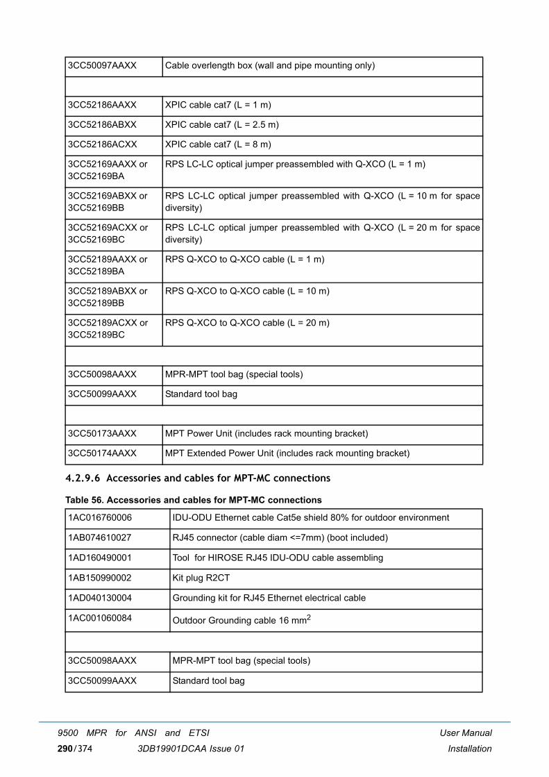
User Manual
Installation
9500 MPR for ANSI and ETSI
3DB19901DCAA Issue 01290/374
4.2.9.6 Accessories and cables for MPT-MC connections
Table 56. Accessories and cables for MPT-MC connections
3CC50097AAXX Cable overlength box (wall and pipe mounting only)
3CC52186AAXX XPIC cable cat7 (L = 1 m)
3CC52186ABXX XPIC cable cat7 (L = 2.5 m)
3CC52186ACXX XPIC cable cat7 (L = 8 m)
3CC52169AAXX or3CC52169BA
RPS LC-LC optical jumper preassembled with Q-XCO (L = 1 m)
3CC52169ABXX or3CC52169BB
RPS LC-LC optical jumper preassembled with Q-XCO (L = 10 m for spacediversity)
3CC52169ACXX or3CC52169BC
RPS LC-LC optical jumper preassembled with Q-XCO (L = 20 m for spacediversity)
3CC52189AAXX or3CC52189BA
RPS Q-XCO to Q-XCO cable (L = 1 m)
3CC52189ABXX or3CC52189BB
RPS Q-XCO to Q-XCO cable (L = 10 m)
3CC52189ACXX or3CC52189BC
RPS Q-XCO to Q-XCO cable (L = 20 m)
3CC50098AAXX MPR-MPT tool bag (special tools)
3CC50099AAXX Standard tool bag
3CC50173AAXX MPT Power Unit (includes rack mounting bracket)
3CC50174AAXX MPT Extended Power Unit (includes rack mounting bracket)
1AC016760006 IDU-ODU Ethernet cable Cat5e shield 80% for outdoor environment
1AB074610027 RJ45 connector (cable diam <=7mm) (boot included)
1AD160490001 Tool for HIROSE RJ45 IDU-ODU cable assembling
1AB150990002 Kit plug R2CT
1AD040130004 Grounding kit for RJ45 Ethernet electrical cable
1AC001060084 Outdoor Grounding cable 16 mm2
3CC50098AAXX MPR-MPT tool bag (special tools)
3CC50099AAXX Standard tool bag

User Manual
Installation
9500 MPR for ANSI and ETSI
3DB19901DCAA Issue 01 291/374
4.2.9.7 Nose adapter for MPT-HC/MPT-HC V2/MPT-MC and MPT-XP
Table 57. Nose adapter for MPT-HC V2/MPT-MC, MPT-XP, and 9558HC
4.2.9.8 Flextwists and N cable for MPT-HC/MPT-HC V2/MPT-MC, MPT-XP, and 9558HC
Table 58. Flextwists and N cable for MPT-HC V2/MPT-MC,MPT-XP, and 9558HC
3CC50174AAXX MPT Extended Power Unit
3DB01460ABXX 5.8 GHz Unlicensed/6 GHz Nose Adapter with waveguide output (for NotIntegrated Antenna)
3CC50172AAXX 5.8GHz Unlicensed/6GHz Nose Adapter with N output (for Not IntegratedAntenna)
3DB10135AAXX 7/8 GHz Nose Adapter (for Not Integrated Antenna)
3CC50125AAXX 11 GHz Nose Adapter (for Not Integrated Antenna)
3CC50179AAXX1
1. MPR-E
13 GHz Nose Adapter (for Not Integrated Antenna)
3CC50177AAXX 15 GHz Nose Adapter (for Not Integrated Antenna)
3CC50178AAXX 18/23/25 Nose Adapter (for Not Integrated Antenna)
3DB02082AAXX 28/38 Nose Adapter (for Not Integrated Antenna)
1AF02951ABAA 5.8 GHz Unlicensed/6 GHz flextwist L = 1m (PDR-UDR)
1AF11977AAAA 7/8 GHz flextwist WR112 L = 1m (PDR84/UBR84)
3CC05751ACAA 11 GHz flextwist L = 0.6m
3CC05751ACAA1
1. MPR-E
13 GHz flextwist L = 0.6m
3CC05750ACAA 15 GHz flextwist L = 0.6m
3CC05749ACAA 18/23/25 GHz flextwist L = 0.6m
3DB00682AAXX 28/38 GHz flextwist L = 0.6m
3CC52198ABXX N-N coaxial cable L=2m
3CC52198AAXX N-N coaxial cable L=1m
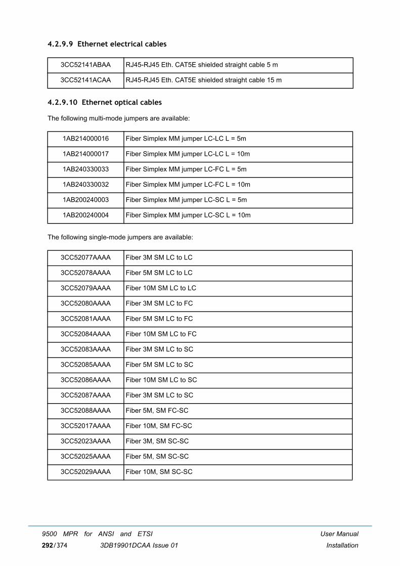
User Manual
Installation
9500 MPR for ANSI and ETSI
3DB19901DCAA Issue 01292/374
4.2.9.9 Ethernet electrical cables
4.2.9.10 Ethernet optical cables
The following multi-mode jumpers are available:
The following single-mode jumpers are available:
3CC52141ABAA RJ45-RJ45 Eth. CAT5E shielded straight cable 5 m
3CC52141ACAA RJ45-RJ45 Eth. CAT5E shielded straight cable 15 m
1AB214000016 Fiber Simplex MM jumper LC-LC L = 5m
1AB214000017 Fiber Simplex MM jumper LC-LC L = 10m
1AB240330033 Fiber Simplex MM jumper LC-FC L = 5m
1AB240330032 Fiber Simplex MM jumper LC-FC L = 10m
1AB200240003 Fiber Simplex MM jumper LC-SC L = 5m
1AB200240004 Fiber Simplex MM jumper LC-SC L = 10m
3CC52077AAAA Fiber 3M SM LC to LC
3CC52078AAAA Fiber 5M SM LC to LC
3CC52079AAAA Fiber 10M SM LC to LC
3CC52080AAAA Fiber 3M SM LC to FC
3CC52081AAAA Fiber 5M SM LC to FC
3CC52084AAAA Fiber 10M SM LC to FC
3CC52083AAAA Fiber 3M SM LC to SC
3CC52085AAAA Fiber 5M SM LC to SC
3CC52086AAAA Fiber 10M SM LC to SC
3CC52087AAAA Fiber 3M SM LC to SC
3CC52088AAAA Fiber 5M, SM FC-SC
3CC52017AAAA Fiber 10M, SM FC-SC
3CC52023AAAA Fiber 3M, SM SC-SC
3CC52025AAAA Fiber 5M, SM SC-SC
3CC52029AAAA Fiber 10M, SM SC-SC
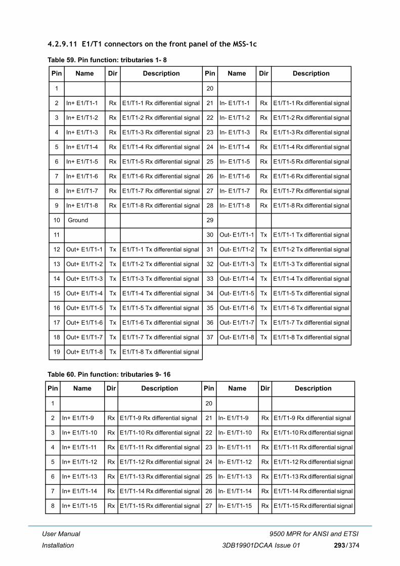
User Manual
Installation
9500 MPR for ANSI and ETSI
3DB19901DCAA Issue 01 293/374
4.2.9.11 E1/T1 connectors on the front panel of the MSS-1c
Table 59. Pin function: tributaries 1- 8
Table 60. Pin function: tributaries 9- 16
Pin Name Dir Description Pin Name Dir Description
1 20
2 In+ E1/T1-1 Rx E1/T1-1 Rx differential signal 21 In- E1/T1-1 Rx E1/T1-1 Rx differential signal
3 In+ E1/T1-2 Rx E1/T1-2 Rx differential signal 22 In- E1/T1-2 Rx E1/T1-2 Rx differential signal
4 In+ E1/T1-3 Rx E1/T1-3 Rx differential signal 23 In- E1/T1-3 Rx E1/T1-3 Rx differential signal
5 In+ E1/T1-4 Rx E1/T1-4 Rx differential signal 24 In- E1/T1-4 Rx E1/T1-4 Rx differential signal
6 In+ E1/T1-5 Rx E1/T1-5 Rx differential signal 25 In- E1/T1-5 Rx E1/T1-5 Rx differential signal
7 In+ E1/T1-6 Rx E1/T1-6 Rx differential signal 26 In- E1/T1-6 Rx E1/T1-6 Rx differential signal
8 In+ E1/T1-7 Rx E1/T1-7 Rx differential signal 27 In- E1/T1-7 Rx E1/T1-7 Rx differential signal
9 In+ E1/T1-8 Rx E1/T1-8 Rx differential signal 28 In- E1/T1-8 Rx E1/T1-8 Rx differential signal
10 Ground 29
11 30 Out- E1/T1-1 Tx E1/T1-1 Tx differential signal
12 Out+ E1/T1-1 Tx E1/T1-1 Tx differential signal 31 Out- E1/T1-2 Tx E1/T1-2 Tx differential signal
13 Out+ E1/T1-2 Tx E1/T1-2 Tx differential signal 32 Out- E1/T1-3 Tx E1/T1-3 Tx differential signal
14 Out+ E1/T1-3 Tx E1/T1-3 Tx differential signal 33 Out- E1/T1-4 Tx E1/T1-4 Tx differential signal
15 Out+ E1/T1-4 Tx E1/T1-4 Tx differential signal 34 Out- E1/T1-5 Tx E1/T1-5 Tx differential signal
16 Out+ E1/T1-5 Tx E1/T1-5 Tx differential signal 35 Out- E1/T1-6 Tx E1/T1-6 Tx differential signal
17 Out+ E1/T1-6 Tx E1/T1-6 Tx differential signal 36 Out- E1/T1-7 Tx E1/T1-7 Tx differential signal
18 Out+ E1/T1-7 Tx E1/T1-7 Tx differential signal 37 Out- E1/T1-8 Tx E1/T1-8 Tx differential signal
19 Out+ E1/T1-8 Tx E1/T1-8 Tx differential signal
Pin Name Dir Description Pin Name Dir Description
1 20
2 In+ E1/T1-9 Rx E1/T1-9 Rx differential signal 21 In- E1/T1-9 Rx E1/T1-9 Rx differential signal
3 In+ E1/T1-10 Rx E1/T1-10 Rx differential signal 22 In- E1/T1-10 Rx E1/T1-10 Rx differential signal
4 In+ E1/T1-11 Rx E1/T1-11 Rx differential signal 23 In- E1/T1-11 Rx E1/T1-11 Rx differential signal
5 In+ E1/T1-12 Rx E1/T1-12 Rx differential signal 24 In- E1/T1-12 Rx E1/T1-12 Rx differential signal
6 In+ E1/T1-13 Rx E1/T1-13 Rx differential signal 25 In- E1/T1-13 Rx E1/T1-13 Rx differential signal
7 In+ E1/T1-14 Rx E1/T1-14 Rx differential signal 26 In- E1/T1-14 Rx E1/T1-14 Rx differential signal
8 In+ E1/T1-15 Rx E1/T1-15 Rx differential signal 27 In- E1/T1-15 Rx E1/T1-15 Rx differential signal
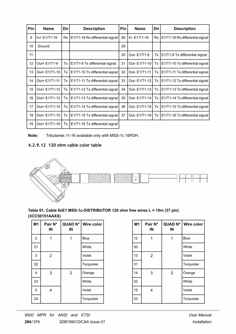
User Manual
Installation
9500 MPR for ANSI and ETSI
3DB19901DCAA Issue 01294/374
Note: Tributaries 11-16 available only with MSS-1c 16PDH.
4.2.9.12 120 ohm cable color table
Table 61. Cable 8xE1 MSS-1c-DISTRIBUTOR 120 ohm free wires L = 10m (37 pin) (3CC50151AAXX)
9 In+ E1/T1-16 Rx E1/T1-16 Rx differential signal 28 In- E1/T1-16 Rx E1/T1-16 Rx differential signal
10 Ground 29
11 30 Out- E1/T1-9 Tx E1/T1-9 Tx differential signal
12 Out+ E1/T1-9 Tx E1/T1-9 Tx differential signal 31 Out- E1/T1-10 Tx E1/T1-10 Tx differential signal
13 Out+ E1/T1-10 Tx E1/T1-10 Tx differential signal 32 Out- E1/T1-11 Tx E1/T1-11 Tx differential signal
14 Out+ E1/T1-11 Tx E1/T1-11 Tx differential signal 33 Out- E1/T1-12 Tx E1/T1-12 Tx differential signal
15 Out+ E1/T1-12 Tx E1/T1-12 Tx differential signal 34 Out- E1/T1-13 Tx E1/T1-13 Tx differential signal
16 Out+ E1/T1-13 Tx E1/T1-13 Tx differential signal 35 Out- E1/T1-14 Tx E1/T1-14 Tx differential signal
17 Out+ E1/T1-14 Tx E1/T1-14 Tx differential signal 36 Out- E1/T1-15 Tx E1/T1-15 Tx differential signal
18 Out+ E1/T1-15 Tx E1/T1-15 Tx differential signal 37 Out- E1/T1-16 Tx E1/T1-16 Tx differential signal
19 Out+ E1/T1-16 Tx E1/T1-16 Tx differential signal
M1 Pair N°IN
QUAD N°IN
Wire color M1 Pair N°IN
QUAD N°IN
Wire color
2 1 1 Blue 12 1 1 Blue
21 White 30 White
3 2 Violet 13 2 Violet
22 Turquoise 31 Turquoise
4 3 2 Orange 14 3 2 Orange
23 White 32 White
5 4 Violet 15 4 Violet
24 Turquoise 33 Turquoise
Pin Name Dir Description Pin Name Dir Description

User Manual
Installation
9500 MPR for ANSI and ETSI
3DB19901DCAA Issue 01 295/374
4.2.9.13 75 ohm cable pin function
Table 62. Cable 8xE1 MSS-1c-DISTRIBUTOR 75 ohm coax Free L = 15m (37 pin) (3CC50152AAXX)
6 5 3 Green 16 5 3 Green
25 White 34 White
7 6 Violet 17 6 Violet
26 Turquoise 35 Turquoise
8 7 4 Brown 18 7 4 Brown
27 White 36 White
9 8 Violet 19 8 Violet
28 Turquoise 37 Turquoise
Pin N° M1 Cable N° Pin N° M1 Cable N°
1 (NB1) - 11 (NB1) -
2 1 12 9
3 2 13 10
4 3 14 11
5 4 15 12
6 5 16 13
7 6 17 14
8 7 18 15
9 8 19 16
10 (NB1) - 20 to 37 (NB2) -
M1 Pair N°IN
QUAD N°IN
Wire color M1 Pair N°IN
QUAD N°IN
Wire color
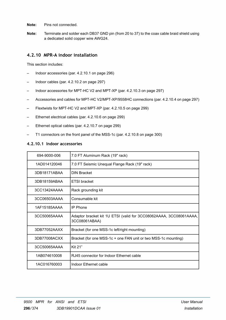
User Manual
Installation
9500 MPR for ANSI and ETSI
3DB19901DCAA Issue 01296/374
Note: Pins not connected.
Note: Terminate and solder each DB37 GND pin (from 20 to 37) to the coax cable braid shield usinga dedicated solid copper wire AWG24.
4.2.10 MPR-A indoor installation
This section includes:
� Indoor accessories (par. 4.2.10.1 on page 296)
� Indoor cables (par. 4.2.10.2 on page 297)
� Indoor accessories for MPT-HC V2 and MPT-XP (par. 4.2.10.3 on page 297)
� Accessories and cables for MPT-HC V2/MPT-XP/9558HC connections (par. 4.2.10.4 on page 297)
� Flextwists for MPT-HC V2 and MPT-XP (par. 4.2.10.5 on page 299)
� Ethernet electrical cables (par. 4.2.10.6 on page 299)
� Ethernet optical cables (par. 4.2.10.7 on page 299)
� T1 connectors on the front panel of the MSS-1c (par. 4.2.10.8 on page 300)
4.2.10.1 Indoor accessories
694-9000-006 7.0 FT Aluminum Rack (19" rack)
1AD014120046 7.0 FT Seismic Unequal Flange Rack (19" rack)
3DB18171ABAA DIN Bracket
3DB18159ABAA ETSI bracket
3CC13424AAAA Rack grounding kit
3CC06503AAAA Consumable kit
1AF15185AAAA IP Phone
3CC50065AAAA Adaptor bracket kit 1U ETSI (valid for 3CC08062AAAA, 3CC08061AAAA,3CC08061ABAA)
3DB77052AAXX Bracket (for one MSS-1c left/right mounting)
3DB77008ACXX Bracket (for one MSS-1c + one FAN unit or two MSS-1c mounting)
3CC50065AAAA Kit 21�
1AB074610008 RJ45 connector for Indoor Ethernet cable
1AC016760003 Indoor Ethernet cable
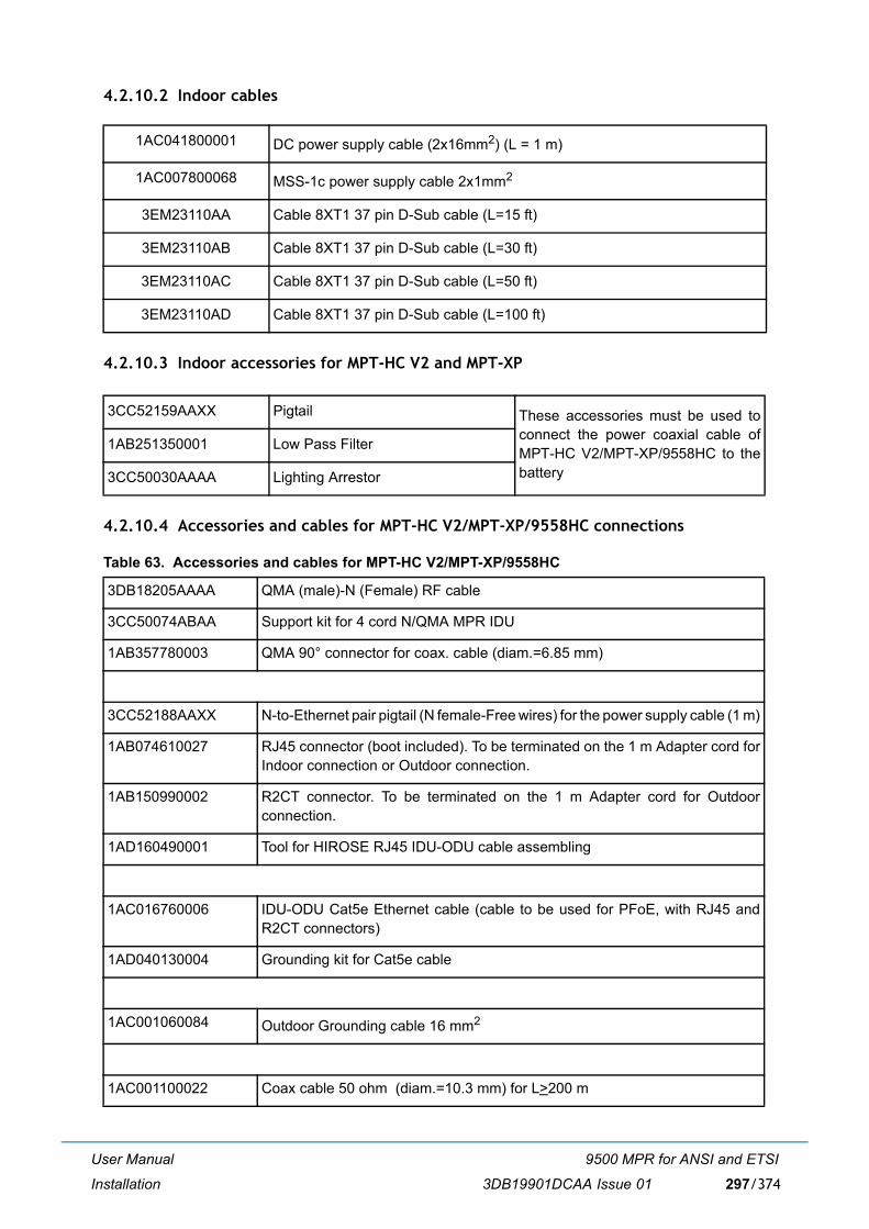
User Manual
Installation
9500 MPR for ANSI and ETSI
3DB19901DCAA Issue 01 297/374
4.2.10.2 Indoor cables
4.2.10.3 Indoor accessories for MPT-HC V2 and MPT-XP
4.2.10.4 Accessories and cables for MPT-HC V2/MPT-XP/9558HC connections
Table 63. Accessories and cables for MPT-HC V2/MPT-XP/9558HC
1AC041800001 DC power supply cable (2x16mm2) (L = 1 m)
1AC007800068 MSS-1c power supply cable 2x1mm2
3EM23110AA Cable 8XT1 37 pin D-Sub cable (L=15 ft)
3EM23110AB Cable 8XT1 37 pin D-Sub cable (L=30 ft)
3EM23110AC Cable 8XT1 37 pin D-Sub cable (L=50 ft)
3EM23110AD Cable 8XT1 37 pin D-Sub cable (L=100 ft)
3CC52159AAXX Pigtail These accessories must be used toconnect the power coaxial cable ofMPT-HC V2/MPT-XP/9558HC to thebattery
1AB251350001 Low Pass Filter
3CC50030AAAA Lighting Arrestor
3DB18205AAAA QMA (male)-N (Female) RF cable
3CC50074ABAA Support kit for 4 cord N/QMA MPR IDU
1AB357780003 QMA 90° connector for coax. cable (diam.=6.85 mm)
3CC52188AAXX N-to-Ethernet pair pigtail (N female-Free wires) for the power supply cable (1 m)
1AB074610027 RJ45 connector (boot included). To be terminated on the 1 m Adapter cord forIndoor connection or Outdoor connection.
1AB150990002 R2CT connector. To be terminated on the 1 m Adapter cord for Outdoorconnection.
1AD160490001 Tool for HIROSE RJ45 IDU-ODU cable assembling
1AC016760006 IDU-ODU Cat5e Ethernet cable (cable to be used for PFoE, with RJ45 andR2CT connectors)
1AD040130004 Grounding kit for Cat5e cable
1AC001060084 Outdoor Grounding cable 16 mm2
1AC001100022 Coax cable 50 ohm (diam.=10.3 mm) for L>200 m
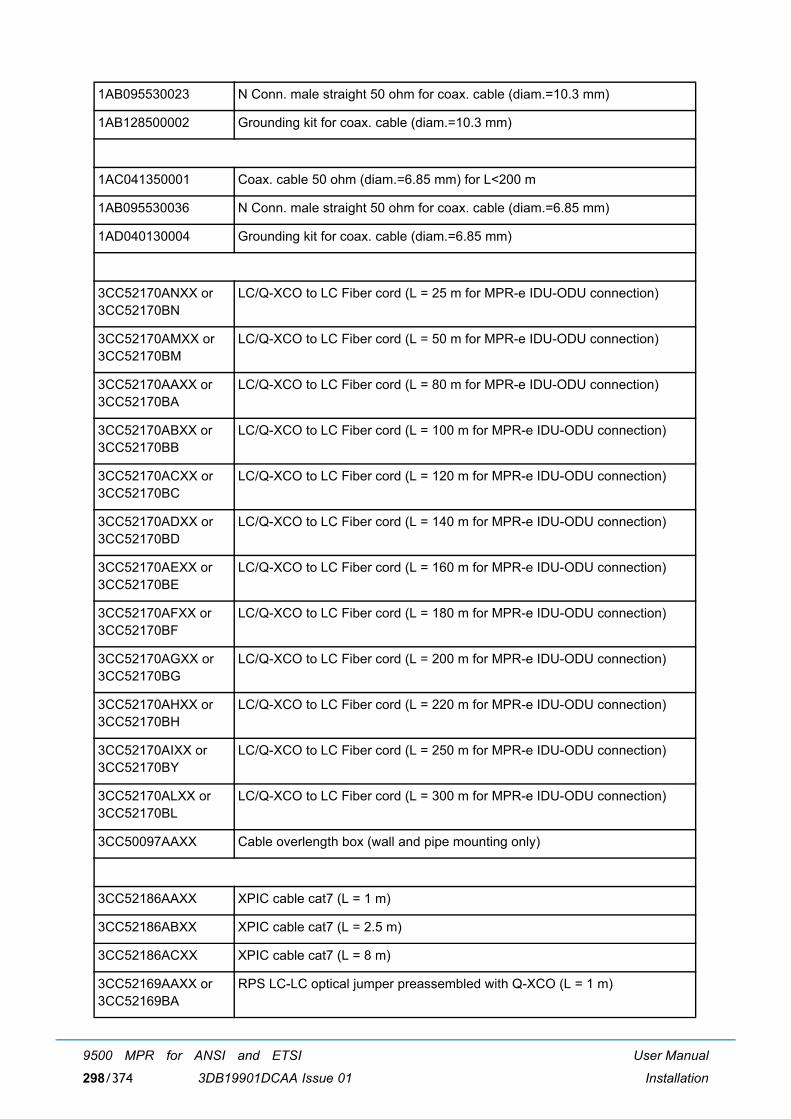
User Manual
Installation
9500 MPR for ANSI and ETSI
3DB19901DCAA Issue 01298/374
1AB095530023 N Conn. male straight 50 ohm for coax. cable (diam.=10.3 mm)
1AB128500002 Grounding kit for coax. cable (diam.=10.3 mm)
1AC041350001 Coax. cable 50 ohm (diam.=6.85 mm) for L<200 m
1AB095530036 N Conn. male straight 50 ohm for coax. cable (diam.=6.85 mm)
1AD040130004 Grounding kit for coax. cable (diam.=6.85 mm)
3CC52170ANXX or3CC52170BN
LC/Q-XCO to LC Fiber cord (L = 25 m for MPR-e IDU-ODU connection)
3CC52170AMXX or3CC52170BM
LC/Q-XCO to LC Fiber cord (L = 50 m for MPR-e IDU-ODU connection)
3CC52170AAXX or3CC52170BA
LC/Q-XCO to LC Fiber cord (L = 80 m for MPR-e IDU-ODU connection)
3CC52170ABXX or3CC52170BB
LC/Q-XCO to LC Fiber cord (L = 100 m for MPR-e IDU-ODU connection)
3CC52170ACXX or3CC52170BC
LC/Q-XCO to LC Fiber cord (L = 120 m for MPR-e IDU-ODU connection)
3CC52170ADXX or3CC52170BD
LC/Q-XCO to LC Fiber cord (L = 140 m for MPR-e IDU-ODU connection)
3CC52170AEXX or3CC52170BE
LC/Q-XCO to LC Fiber cord (L = 160 m for MPR-e IDU-ODU connection)
3CC52170AFXX or3CC52170BF
LC/Q-XCO to LC Fiber cord (L = 180 m for MPR-e IDU-ODU connection)
3CC52170AGXX or3CC52170BG
LC/Q-XCO to LC Fiber cord (L = 200 m for MPR-e IDU-ODU connection)
3CC52170AHXX or3CC52170BH
LC/Q-XCO to LC Fiber cord (L = 220 m for MPR-e IDU-ODU connection)
3CC52170AIXX or3CC52170BY
LC/Q-XCO to LC Fiber cord (L = 250 m for MPR-e IDU-ODU connection)
3CC52170ALXX or3CC52170BL
LC/Q-XCO to LC Fiber cord (L = 300 m for MPR-e IDU-ODU connection)
3CC50097AAXX Cable overlength box (wall and pipe mounting only)
3CC52186AAXX XPIC cable cat7 (L = 1 m)
3CC52186ABXX XPIC cable cat7 (L = 2.5 m)
3CC52186ACXX XPIC cable cat7 (L = 8 m)
3CC52169AAXX or3CC52169BA
RPS LC-LC optical jumper preassembled with Q-XCO (L = 1 m)
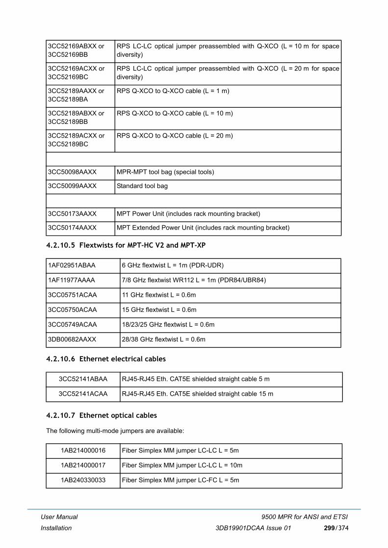
User Manual
Installation
9500 MPR for ANSI and ETSI
3DB19901DCAA Issue 01 299/374
4.2.10.5 Flextwists for MPT-HC V2 and MPT-XP
4.2.10.6 Ethernet electrical cables
4.2.10.7 Ethernet optical cables
The following multi-mode jumpers are available:
3CC52169ABXX or3CC52169BB
RPS LC-LC optical jumper preassembled with Q-XCO (L = 10 m for spacediversity)
3CC52169ACXX or3CC52169BC
RPS LC-LC optical jumper preassembled with Q-XCO (L = 20 m for spacediversity)
3CC52189AAXX or3CC52189BA
RPS Q-XCO to Q-XCO cable (L = 1 m)
3CC52189ABXX or3CC52189BB
RPS Q-XCO to Q-XCO cable (L = 10 m)
3CC52189ACXX or3CC52189BC
RPS Q-XCO to Q-XCO cable (L = 20 m)
3CC50098AAXX MPR-MPT tool bag (special tools)
3CC50099AAXX Standard tool bag
3CC50173AAXX MPT Power Unit (includes rack mounting bracket)
3CC50174AAXX MPT Extended Power Unit (includes rack mounting bracket)
1AF02951ABAA 6 GHz flextwist L = 1m (PDR-UDR)
1AF11977AAAA 7/8 GHz flextwist WR112 L = 1m (PDR84/UBR84)
3CC05751ACAA 11 GHz flextwist L = 0.6m
3CC05750ACAA 15 GHz flextwist L = 0.6m
3CC05749ACAA 18/23/25 GHz flextwist L = 0.6m
3DB00682AAXX 28/38 GHz flextwist L = 0.6m
3CC52141ABAA RJ45-RJ45 Eth. CAT5E shielded straight cable 5 m
3CC52141ACAA RJ45-RJ45 Eth. CAT5E shielded straight cable 15 m
1AB214000016 Fiber Simplex MM jumper LC-LC L = 5m
1AB214000017 Fiber Simplex MM jumper LC-LC L = 10m
1AB240330033 Fiber Simplex MM jumper LC-FC L = 5m
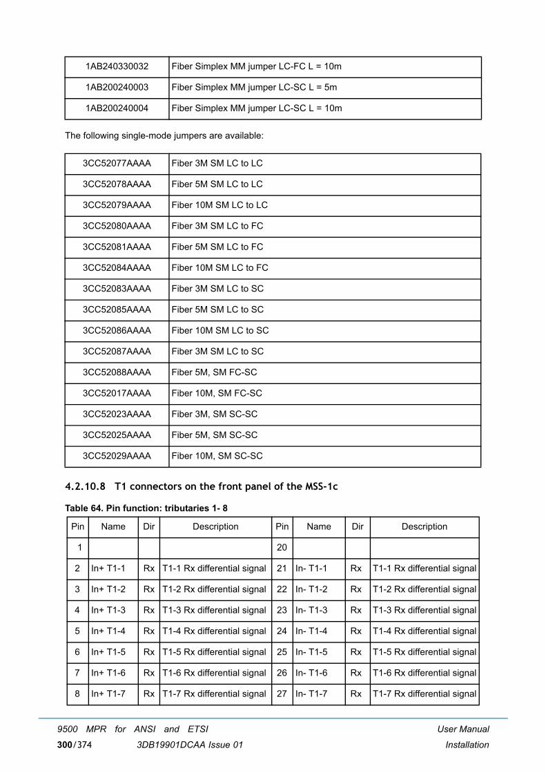
User Manual
Installation
9500 MPR for ANSI and ETSI
3DB19901DCAA Issue 01300/374
The following single-mode jumpers are available:
4.2.10.8 T1 connectors on the front panel of the MSS-1c
Table 64. Pin function: tributaries 1- 8
1AB240330032 Fiber Simplex MM jumper LC-FC L = 10m
1AB200240003 Fiber Simplex MM jumper LC-SC L = 5m
1AB200240004 Fiber Simplex MM jumper LC-SC L = 10m
3CC52077AAAA Fiber 3M SM LC to LC
3CC52078AAAA Fiber 5M SM LC to LC
3CC52079AAAA Fiber 10M SM LC to LC
3CC52080AAAA Fiber 3M SM LC to FC
3CC52081AAAA Fiber 5M SM LC to FC
3CC52084AAAA Fiber 10M SM LC to FC
3CC52083AAAA Fiber 3M SM LC to SC
3CC52085AAAA Fiber 5M SM LC to SC
3CC52086AAAA Fiber 10M SM LC to SC
3CC52087AAAA Fiber 3M SM LC to SC
3CC52088AAAA Fiber 5M, SM FC-SC
3CC52017AAAA Fiber 10M, SM FC-SC
3CC52023AAAA Fiber 3M, SM SC-SC
3CC52025AAAA Fiber 5M, SM SC-SC
3CC52029AAAA Fiber 10M, SM SC-SC
Pin Name Dir Description Pin Name Dir Description
1 20
2 In+ T1-1 Rx T1-1 Rx differential signal 21 In- T1-1 Rx T1-1 Rx differential signal
3 In+ T1-2 Rx T1-2 Rx differential signal 22 In- T1-2 Rx T1-2 Rx differential signal
4 In+ T1-3 Rx T1-3 Rx differential signal 23 In- T1-3 Rx T1-3 Rx differential signal
5 In+ T1-4 Rx T1-4 Rx differential signal 24 In- T1-4 Rx T1-4 Rx differential signal
6 In+ T1-5 Rx T1-5 Rx differential signal 25 In- T1-5 Rx T1-5 Rx differential signal
7 In+ T1-6 Rx T1-6 Rx differential signal 26 In- T1-6 Rx T1-6 Rx differential signal
8 In+ T1-7 Rx T1-7 Rx differential signal 27 In- T1-7 Rx T1-7 Rx differential signal
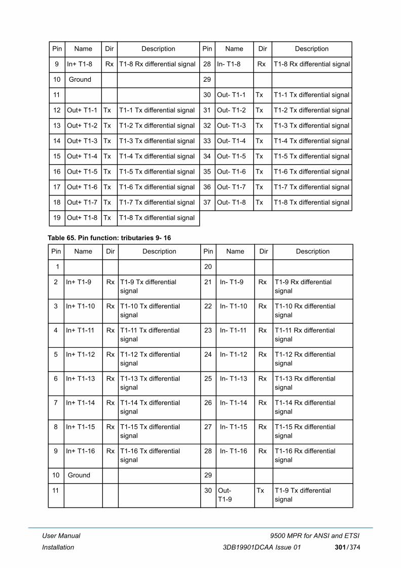
User Manual
Installation
9500 MPR for ANSI and ETSI
3DB19901DCAA Issue 01 301/374
Table 65. Pin function: tributaries 9- 16
9 In+ T1-8 Rx T1-8 Rx differential signal 28 In- T1-8 Rx T1-8 Rx differential signal
10 Ground 29
11 30 Out- T1-1 Tx T1-1 Tx differential signal
12 Out+ T1-1 Tx T1-1 Tx differential signal 31 Out- T1-2 Tx T1-2 Tx differential signal
13 Out+ T1-2 Tx T1-2 Tx differential signal 32 Out- T1-3 Tx T1-3 Tx differential signal
14 Out+ T1-3 Tx T1-3 Tx differential signal 33 Out- T1-4 Tx T1-4 Tx differential signal
15 Out+ T1-4 Tx T1-4 Tx differential signal 34 Out- T1-5 Tx T1-5 Tx differential signal
16 Out+ T1-5 Tx T1-5 Tx differential signal 35 Out- T1-6 Tx T1-6 Tx differential signal
17 Out+ T1-6 Tx T1-6 Tx differential signal 36 Out- T1-7 Tx T1-7 Tx differential signal
18 Out+ T1-7 Tx T1-7 Tx differential signal 37 Out- T1-8 Tx T1-8 Tx differential signal
19 Out+ T1-8 Tx T1-8 Tx differential signal
Pin Name Dir Description Pin Name Dir Description
1 20
2 In+ T1-9 Rx T1-9 Tx differentialsignal
21 In- T1-9 Rx T1-9 Rx differentialsignal
3 In+ T1-10 Rx T1-10 Tx differentialsignal
22 In- T1-10 Rx T1-10 Rx differentialsignal
4 In+ T1-11 Rx T1-11 Tx differentialsignal
23 In- T1-11 Rx T1-11 Rx differentialsignal
5 In+ T1-12 Rx T1-12 Tx differentialsignal
24 In- T1-12 Rx T1-12 Rx differentialsignal
6 In+ T1-13 Rx T1-13 Tx differentialsignal
25 In- T1-13 Rx T1-13 Rx differentialsignal
7 In+ T1-14 Rx T1-14 Tx differentialsignal
26 In- T1-14 Rx T1-14 Rx differentialsignal
8 In+ T1-15 Rx T1-15 Tx differentialsignal
27 In- T1-15 Rx T1-15 Rx differentialsignal
9 In+ T1-16 Rx T1-16 Tx differentialsignal
28 In- T1-16 Rx T1-16 Rx differentialsignal
10 Ground 29
11 30 Out- T1-9
Tx T1-9 Tx differentialsignal
Pin Name Dir Description Pin Name Dir Description
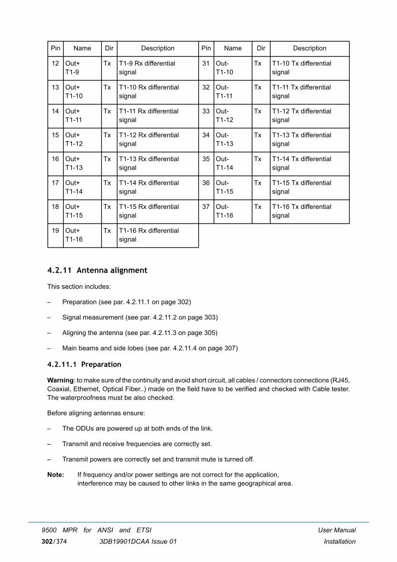
User Manual
Installation
9500 MPR for ANSI and ETSI
3DB19901DCAA Issue 01302/374
4.2.11 Antenna alignment
This section includes:
� Preparation (see par. 4.2.11.1 on page 302)
� Signal measurement (see par. 4.2.11.2 on page 303)
� Aligning the antenna (see par. 4.2.11.3 on page 305)
� Main beams and side lobes (see par. 4.2.11.4 on page 307)
4.2.11.1 Preparation
Warning: to make sure of the continuity and avoid short circuit, all cables / connectors connections (RJ45,Coaxial, Ethernet, Optical Fiber..) made on the field have to be verified and checked with Cable tester.The waterproofness must be also checked.
Before aligning antennas ensure:
� The ODUs are powered up at both ends of the link.
� Transmit and receive frequencies are correctly set.
� Transmit powers are correctly set and transmit mute is turned off.
Note: If frequency and/or power settings are not correct for the application, interference may be caused to other links in the same geographical area.
12 Out+ T1-9
Tx T1-9 Rx differentialsignal
31 Out- T1-10
Tx T1-10 Tx differentialsignal
13 Out+ T1-10
Tx T1-10 Rx differentialsignal
32 Out- T1-11
Tx T1-11 Tx differentialsignal
14 Out+ T1-11
Tx T1-11 Rx differentialsignal
33 Out- T1-12
Tx T1-12 Tx differentialsignal
15 Out+ T1-12
Tx T1-12 Rx differentialsignal
34 Out- T1-13
Tx T1-13 Tx differentialsignal
16 Out+ T1-13
Tx T1-13 Rx differentialsignal
35 Out- T1-14
Tx T1-14 Tx differentialsignal
17 Out+ T1-14
Tx T1-14 Rx differentialsignal
36 Out- T1-15
Tx T1-15 Tx differentialsignal
18 Out+ T1-15
Tx T1-15 Rx differentialsignal
37 Out- T1-16
Tx T1-16 Tx differentialsignal
19 Out+ T1-16
Tx T1-16 Rx differentialsignal
Pin Name Dir Description Pin Name Dir Description
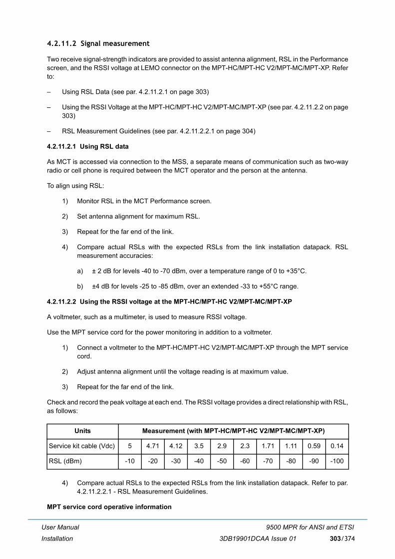
User Manual
Installation
9500 MPR for ANSI and ETSI
3DB19901DCAA Issue 01 303/374
4.2.11.2 Signal measurement
Two receive signal-strength indicators are provided to assist antenna alignment, RSL in the Performancescreen, and the RSSI voltage at LEMO connector on the MPT-HC/MPT-HC V2/MPT-MC/MPT-XP. Referto:
� Using RSL Data (see par. 4.2.11.2.1 on page 303)
� Using the RSSI Voltage at the MPT-HC/MPT-HC V2/MPT-MC/MPT-XP (see par. 4.2.11.2.2 on page303)
� RSL Measurement Guidelines (see par. 4.2.11.2.2.1 on page 304)
4.2.11.2.1 Using RSL data
As MCT is accessed via connection to the MSS, a separate means of communication such as two-wayradio or cell phone is required between the MCT operator and the person at the antenna.
To align using RSL:
1) Monitor RSL in the MCT Performance screen.
2) Set antenna alignment for maximum RSL.
3) Repeat for the far end of the link.
4) Compare actual RSLs with the expected RSLs from the link installation datapack. RSLmeasurement accuracies:
a) ± 2 dB for levels -40 to -70 dBm, over a temperature range of 0 to +35°C.
b) ±4 dB for levels -25 to -85 dBm, over an extended -33 to +55°C range.
4.2.11.2.2 Using the RSSI voltage at the MPT-HC/MPT-HC V2/MPT-MC/MPT-XP
A voltmeter, such as a multimeter, is used to measure RSSI voltage.
Use the MPT service cord for the power monitoring in addition to a voltmeter.
1) Connect a voltmeter to the MPT-HC/MPT-HC V2/MPT-MC/MPT-XP through the MPT servicecord.
2) Adjust antenna alignment until the voltage reading is at maximum value.
3) Repeat for the far end of the link.
Check and record the peak voltage at each end. The RSSI voltage provides a direct relationship with RSL,as follows:
4) Compare actual RSLs to the expected RSLs from the link installation datapack. Refer to par.4.2.11.2.2.1 - RSL Measurement Guidelines.
MPT service cord operative information
Units Measurement (with MPT-HC/MPT-HC V2/MPT-MC/MPT-XP)
Service kit cable (Vdc) 5 4.71 4.12 3.5 2.9 2.3 1.71 1.11 0.59 0.14
RSL (dBm) -10 -20 -30 -40 -50 -60 -70 -80 -90 -100
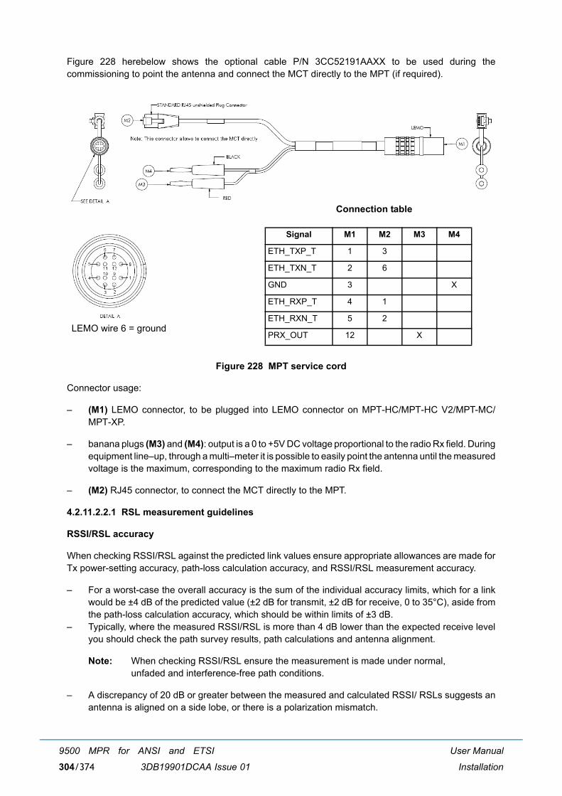
User Manual
Installation
9500 MPR for ANSI and ETSI
3DB19901DCAA Issue 01304/374
Figure 228 herebelow shows the optional cable P/N 3CC52191AAXX to be used during thecommissioning to point the antenna and connect the MCT directly to the MPT (if required).
Figure 228 MPT service cord
Connector usage:
� (M1) LEMO connector, to be plugged into LEMO connector on MPT-HC/MPT-HC V2/MPT-MC/MPT-XP.
� banana plugs (M3) and (M4): output is a 0 to +5V DC voltage proportional to the radio Rx field. Duringequipment line�up, through a multi�meter it is possible to easily point the antenna until the measuredvoltage is the maximum, corresponding to the maximum radio Rx field.
� (M2) RJ45 connector, to connect the MCT directly to the MPT.
4.2.11.2.2.1 RSL measurement guidelines
RSSI/RSL accuracy
When checking RSSI/RSL against the predicted link values ensure appropriate allowances are made forTx power-setting accuracy, path-loss calculation accuracy, and RSSI/RSL measurement accuracy.
� For a worst-case the overall accuracy is the sum of the individual accuracy limits, which for a linkwould be ±4 dB of the predicted value (±2 dB for transmit, ±2 dB for receive, 0 to 35°C), aside fromthe path-loss calculation accuracy, which should be within limits of ±3 dB.
� Typically, where the measured RSSI/RSL is more than 4 dB lower than the expected receive levelyou should check the path survey results, path calculations and antenna alignment.
Note: When checking RSSI/RSL ensure the measurement is made under normal, unfaded and interference-free path conditions.
� A discrepancy of 20 dB or greater between the measured and calculated RSSI/ RSLs suggests anantenna is aligned on a side lobe, or there is a polarization mismatch.
LEMO wire 6 = ground
Connection table
Signal M1 M2 M3 M4
ETH_TXP_T 1 3
ETH_TXN_T 2 6
GND 3 X
ETH_RXP_T 4 1
ETH_RXN_T 5 2
PRX_OUT 12 X

User Manual
Installation
9500 MPR for ANSI and ETSI
3DB19901DCAA Issue 01 305/374
Note: Without any received signal (Tx mute on the remote MPT for example), the RSL valuedisplayed may be more than -100dBm. This depends of the channelisation/modulationsettings
4.2.11.3 Aligning the antenna
Antenna alignment involves adjusting the direction of each antenna until the received signal strengthreaches its maximum level at each end of the link.Fine adjustment for azimuth (horizontal angle) andelevation (vertical angle) is built into each antenna mount.
Adjustment procedures will be provided with each antenna.If the horizontal adjuster does not providesufficient range to locate the main beam, the antenna mounting brackets will need to be loosened andthe antenna swiveled on its pole mount to locate the beam.
Before doing this ensure the horizontal adjuster is set for mid-travel.
Some mounts for larger antennas have a separately clamped swivel base to allow the loosened antennato swivel on it without fear of slippage down the pole. Where such a mount is not provided a temporaryswivel clamp can often be provided using a pair of pipe brackets bolted together immediately below theantenna mount.
Note: Ensure antennas are aligned on the main beam, and not a side lobe. For guidance, refer to the sections Locating the Main Beam (see par. 4.2.11.4.1 on page 307) and Tracking Path Error (see par. 4.2.11.4.2 on page 308). Ensure ATPC is turned off during the alignment procedure.
4.2.11.3.1 Standard alignment procedure
To align an antenna:
1) Loosen the azimuth adjuster on the antenna mount (horizontal angle) and adjust azimuthposition for maximum signal strength. Ensure antennas are aligned on the main beam, and nota side lobe.
2) Tighten the azimuth securing mechanism. Ensure signal strength does not drop as it istightened.
3) Loosen the elevation adjuster (vertical angle) and adjust for maximum signal strength. Ensureantennas are aligned on the main beam, and not a side lobe.
4) Tighten the elevation securing mechanism. Ensure signal strength does not drop as it istightened. The terminal is now aligned and ready to carry operational traffic.
5) Record RSL and/or RSSI voltage in the commissioning log.
4.2.11.3.2 Alignment procedure for dual polarized antenna
The following procedure details steps required to:
� Check and if necessary set feedhead alignment using a spirit level.
� Align the antennas at each end using just one of the feeds, H or V. (Standard co-plane antennaalignment).
� Check cross pole discrimination (XPD).

User Manual
Installation
9500 MPR for ANSI and ETSI
3DB19901DCAA Issue 01306/374
Note: Optimize alignment of the feed-heads to achieve maximum cross polarization discrimination. This procedure assumes that the antennas used at each end of the link do comply with their cross-polarization discrimination specification. If in doubt, refer to the antenna supplier.
Procedure:
[1] Static Feedhead Alignment
During antenna installation and before weatherproofing is installed, use a spirit level to check andset exact vertical / horizontal alignment of the feeds:
� Do not rely on antenna markings as these will not be accurate where a mount is not perfectlylevel.
� Set the spirit level against the flange of the feedhead. Take care that only the flange of thefeedhead is measured, so that no error is introduced by any minor misalignment of the matingflexible waveguide flange. See Figure 229
Figure 229 Checking feedhead flange with a spirit level
� If not exactly vertical or horizontal, adjust the feedhead skew angle (rotate the feedhead) untilcorrect (spirit level bubble is precisely centered). For a typical feedhead check both flanges forlevel, using an end point half way between the level points of the two flanges should there beany discrepancy between the two.
[2] Align Antennas
Align the antennas at both ends using the standard (co-plane) alignment procedure, but using just oneof the feeds, V or H. Refer to Standard Alignment Procedure (see par. 4.2.11.3.1 on page 305). Whencorrect, proceed to step 3.
[3] Power-up both V and H links and check they are operating normally and are alarm-free. Use thePerformance screens to check that:
� Tx power measurements are within 1 dB (typically). If not check Tx power settings.

User Manual
Installation
9500 MPR for ANSI and ETSI
3DB19901DCAA Issue 01 307/374
� RSL measurements are within 2 dB. See Using RSL Data (see par. 4.2.11.2.1 on page 303)for guidance on measurement accuracy.
� Links are operating error-free.
Note: Where there is potential for interference from other links in the same geographical area, check by turning the far end transmitter(s) off and measuring the local end RSL on both V and H feeds.
[4] Measure the actual V and H signal discrimination from each antenna.
� Where measured XPDs are better than 25 dB no further adjustment is needed
� Where less than 25 dB proceed to the next step.
Note: The alignment procedures listed under steps 1 and 2 should result in a discrimination of betterthan 25dB. However, for best results and greater operating margins during fading, feedheadalignment should be optimized using the following procedure.
[5] Optimize End-End Feedhead Alignment
This procedure corrects for any minor rotational alignment between antennas at each end.
One antenna is the reference antenna and its feed-head assembly is not adjusted during thisprocedure.
Note: Only check/adjust skew angles on one antenna. If both antennas are adjusted and re-adjustedthere is potential for progressive misalignment to occur. Select one antenna as the referenceantenna. On long hops and where fading is prevalent there is potential for the V and H planepaths to be affected differently and to therefore exhibit variable cross-polarizationdiscrimination. This alignment procedure must be conducted during periods of known, stablepath conditions.
[6] Adjust the feedhead skew angle of the antenna for maximum XPD on both V and H link. If themaximums for each are at (slightly) different angles, adjust for a mid-point.
Note: Ensure that as you adjust the skew angle, the physical antenna alignment does not shift, whichwould make it necessary to repeat step 2. Check that antenna mounting bolts and azimuth andelevation adjuster locks have been correctly tightened. The maximum points may be quitesharp, rotate the feedhead slowly to ensure they are not missed.
[7] Check the XPD on the link at the reference end of the link, which should be within 1 to 2 dB of themeasurements at the adjusted end.
[8] On completion ensure feedhead bolts are correctly tightened - check that XPDs do not change duringtightening.
[9] Retain feed-head adjustment data for the commissioning records.
4.2.11.4 Main beams and side lobes
This section describes how to locate the main beam, and typical tracking path errors.
4.2.11.4.1 Locating the main beam
Ensure the antennas are aligned on the main beam, and not a side lobe.

User Manual
Installation
9500 MPR for ANSI and ETSI
3DB19901DCAA Issue 01308/374
Once a measurable signal is observed, very small alignment adjustments are required to locate the mainbeam. For instance, a 1.2m antenna at 23 GHz typically has 0.9° of adjustment from center of main beamto the first null (0.4° to the -3 dB point). Antenna movement across the main beam will result in a rapidrise and fall of signal level. As a guide, 1 degree of beam width is equivalent to moving approximately 1.0mm around a standard 114 mm (4.5 in.) diameter O/D pipe.
Antennas can be verified as being on main beam (as opposed to a side lobe) by comparing measuredreceive signal level with the calculated level.
Signal strength readings are usually measurable when at least a main beam at one end and first side lobesat the other are aligned.
The strongest signal occurs at the center of the main beam. The highest first lobe signal is typically 20 -25 dB less than the main beam signal. When both antennas are aligned for maximum main beam signalstrength, the receive signal level should be within 2 dB of the calculated level for the path. This calculatedlevel should be included in the installation datapack for the link.
Figure 230 is an example of a head-on, conceptual view of the beam signal strength, with concentric ringsof side lobe peaks and troughs radiating outward from the main beam.
Figure 230 Indicative head-on signal pattern for a parabolic antenna
4.2.11.4.2 Tracking path error
Side lobe signal readings can be confused with main beam readings. This is particularly true for the firstside lobe as the signal level at its center is greater than the signal level at the edges of the main beam,and if tracking on an incorrect elevation (or azimuth) a false impression of main beam reception can beobtained. This illustration shows an example of this with a simplified head-on view of an antenna radiationpattern, and tracking paths for three elevation settings.

User Manual
Installation
9500 MPR for ANSI and ETSI
3DB19901DCAA Issue 01 309/374
Figure 231 Example Tracking Path Signals
Line AA represents the azimuth tracking path of a properly aligned antenna.The main beam is at point2, and the first side lobes at points 1 and 3. Line BB represents the azimuth tracking path with the antennatilted down slightly. Signal strength readings show only the first side lobe peaks, 4 and 5. In some instancesthe side lobe peaks are unequal due to antenna characteristics, which can lead to the larger peak beingmistaken for the main beam. The correct method for locating the main beam in this case is to set theazimuth position midway between the first side lobe peaks, and then adjust the elevation for maximumsignal.
Line CC represents an azimuth tracking path with the antenna tilted down further still. The first side lobesignal peaks (6 and 7) appear as one peak, leading to a mistaken interpretation of a main beam. Thecorrect method for locating the main beam is to set the azimuth at mid peak, between 6 and 7, and thenadjust elevation for maximum signal.
This first side lobe peaking is probably the most frequent cause of misalignment in both azimuth andelevation, especially so if one side lobe peaks higher than the other, as shown in Figure 232 A commonerror is to move the antenna left to right along line DD, or top to bottom along line EE, always ending upwith the maximum signal at position 1.
Figure 232 Example tracking path signals on the first side lobe
4.3 Software local copy
This section explains how to prepare the WebEML Suite and Craft Terminal environment in your PC.
� Getting started (par. 4.3.1 on page 309)
� PC characteristics (par. 4.3.2 on page 310)
� Local copy of the software package (SWP) to the PC (par. 4.3.3 on page 311)
� Local copy the WebEML to PC (par. 4.3.4 on page 312)
� Configure PC network card to connect to NE (par. 4.3.5 on page 318)
4.3.1 Getting started
Note: Read the following before starting.
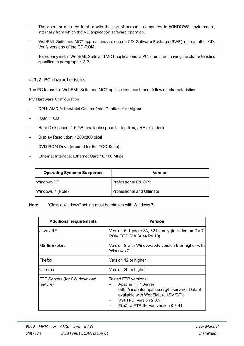
User Manual
Installation
9500 MPR for ANSI and ETSI
3DB19901DCAA Issue 01310/374
� The operator must be familiar with the use of personal computers in WINDOWS environment,internally from which the NE application software operates.
� WebEML Suite and MCT applications are on one CD. Software Package (SWP) is on another CD.Verify versions of the CD-ROM.
� To properly install WebEML Suite and MCT applications, a PC is required, having the characteristicsspecified in paragraph 4.3.2.
4.3.2 PC characteristics
The PC to use for WebEML Suite and MCT applications must meet following characteristics:
PC Hardware Configuration:
� CPU: AMD Atlhon/Intel Celeron/Intel Pentium 4 or higher
� RAM: 1 GB
� Hard Disk space: 1.5 GB (available space for log files, JRE excluded)
� Display Resolution: 1280x800 pixel
� DVD-ROM Drive (needed for the TCO Suite)
� Ethernet Interface: Ethernet Card 10/100 Mbps
Note: "Classic windows" setting must be chosen with Windows 7.
Operating Systems Supported Version
Windows XP Professional Ed. SP3
Windows 7 (Note) Professional and Ultimate
Additional requirements Version
Java JRE Version 6, Update 33, 32 bit only (included on DVD-ROM TCO SW Suite R4.10)
MS IE Explorer Version 8 with Windows XP, version 9 or higher withWindows 7
Firefox Version 12 or higher
Chrome Version 20 or higher
FTP Servers (for SW download feature)
Tested FTP versions:� Apache FTP Server
(http:/incubator.apache.org/ftpserver/). Defaultavailable with WebEML (JUSM/CT);
� VSFTPD, version 2.0.5;� FileZilla FTP Server, version 0.9.41
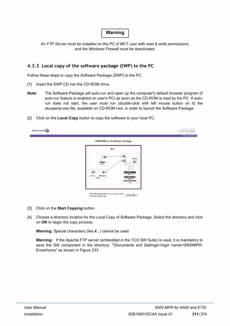
User Manual
Installation
9500 MPR for ANSI and ETSI
3DB19901DCAA Issue 01 311/374
An FTP Server must be installed on the PC of MCT user with read & write permissions, and the Windows Firewall must be deactivated.
4.3.3 Local copy of the software package (SWP) to the PC
Follow these steps to copy the Software Package (SWP) to the PC.
[1] Insert the SWP CD into the CD-ROM drive.
Note: The Software Package will auto-run and open up the computer's default browser program (ifauto-run feature is enabled on user's PC) as soon as the CD-ROM is read by the PC. If auto-run does not start, the user must run (double-click with left mouse button on it) thealuopener.exe file, available on CD-ROM root, in order to launch the Software Package.
[2] Click on the Local Copy button to copy the software to your local PC.
[3] Click on the Start Copying button.
[4] Choose a directory location for the Local Copy of Software Package. Select the directory and clickon OK to begin the copy process.
Warning: Special characters (like #...) cannot be used.
Warning: If the Apache FTP server (embedded in the TCO SW Suite) is used, it is mandatory tosave the SW component in the directory: "\Documents and Settings\<login name>\9500MPR-E\res\home" as shown in Figure 233.
Warning
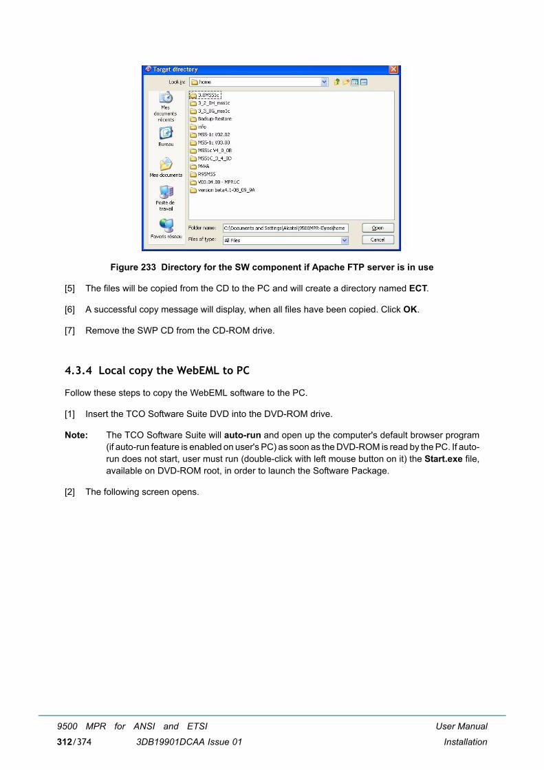
User Manual
Installation
9500 MPR for ANSI and ETSI
3DB19901DCAA Issue 01312/374
Figure 233 Directory for the SW component if Apache FTP server is in use
[5] The files will be copied from the CD to the PC and will create a directory named ECT.
[6] A successful copy message will display, when all files have been copied. Click OK.
[7] Remove the SWP CD from the CD-ROM drive.
4.3.4 Local copy the WebEML to PC
Follow these steps to copy the WebEML software to the PC.
[1] Insert the TCO Software Suite DVD into the DVD-ROM drive.
Note: The TCO Software Suite will auto-run and open up the computer's default browser program(if auto-run feature is enabled on user's PC) as soon as the DVD-ROM is read by the PC. If auto-run does not start, user must run (double-click with left mouse button on it) the Start.exe file,available on DVD-ROM root, in order to launch the Software Package.
[2] The following screen opens.
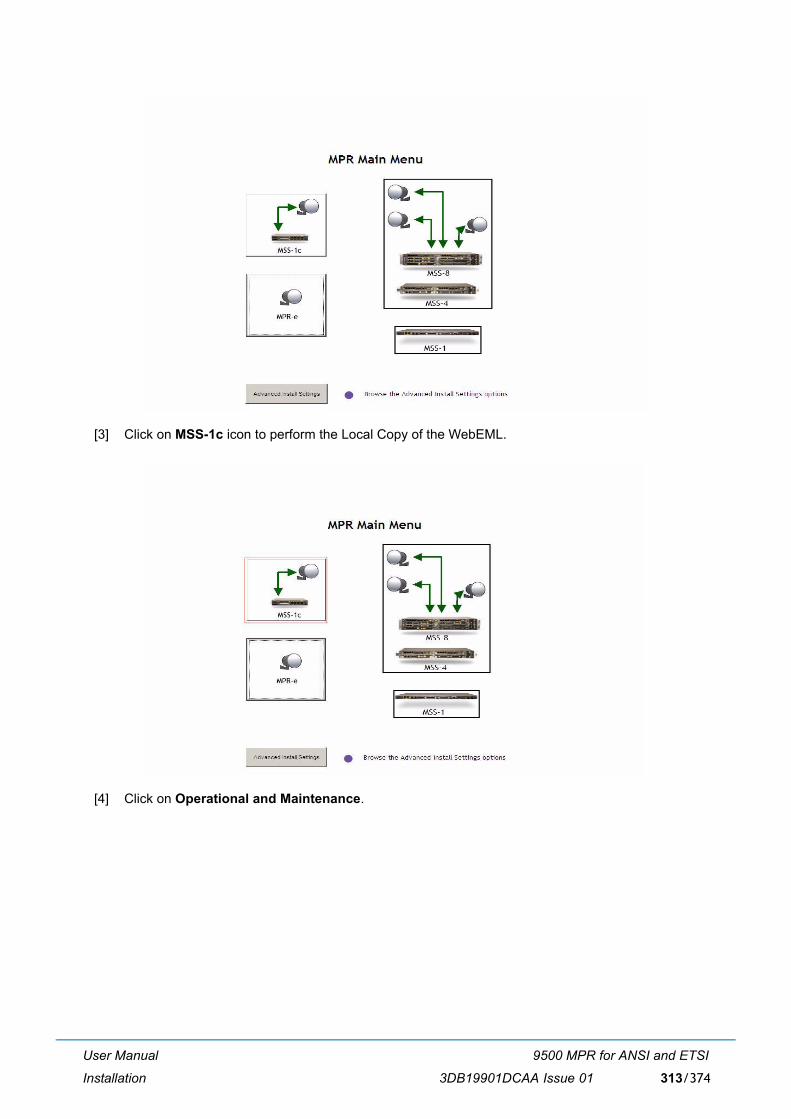
User Manual
Installation
9500 MPR for ANSI and ETSI
3DB19901DCAA Issue 01 313/374
[3] Click on MSS-1c icon to perform the Local Copy of the WebEML.
[4] Click on Operational and Maintenance.
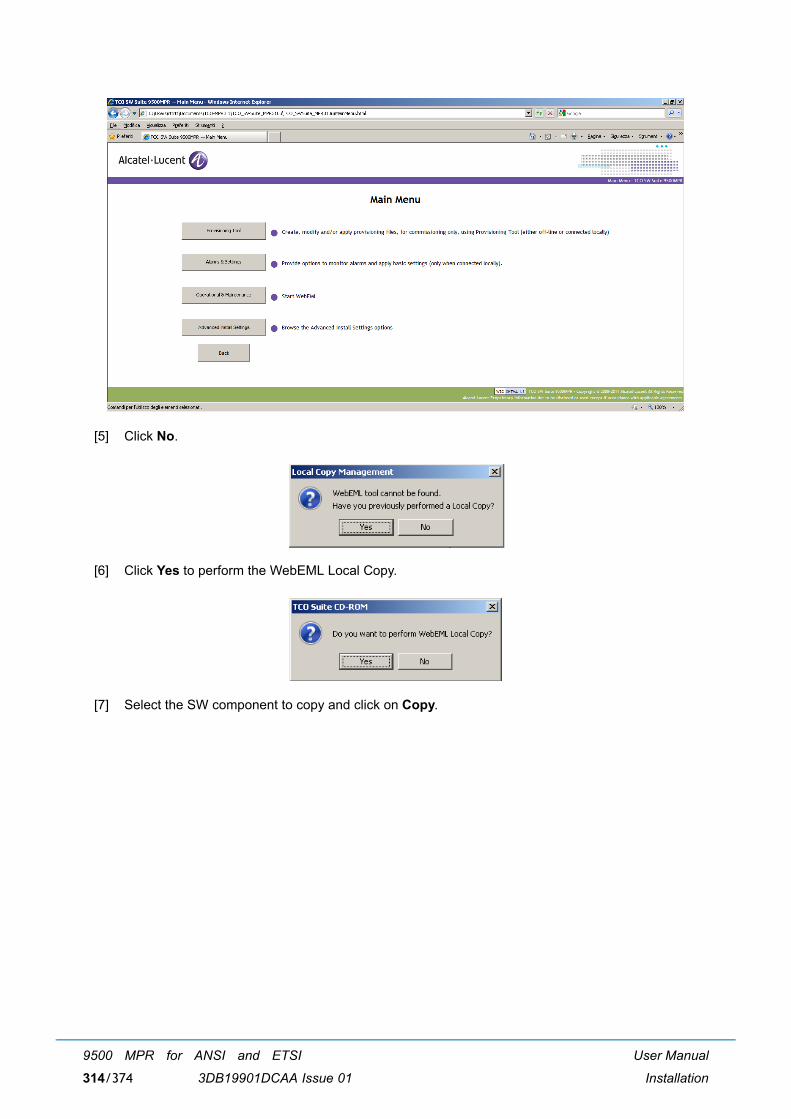
User Manual
Installation
9500 MPR for ANSI and ETSI
3DB19901DCAA Issue 01314/374
[5] Click No.
[6] Click Yes to perform the WebEML Local Copy.
[7] Select the SW component to copy and click on Copy.
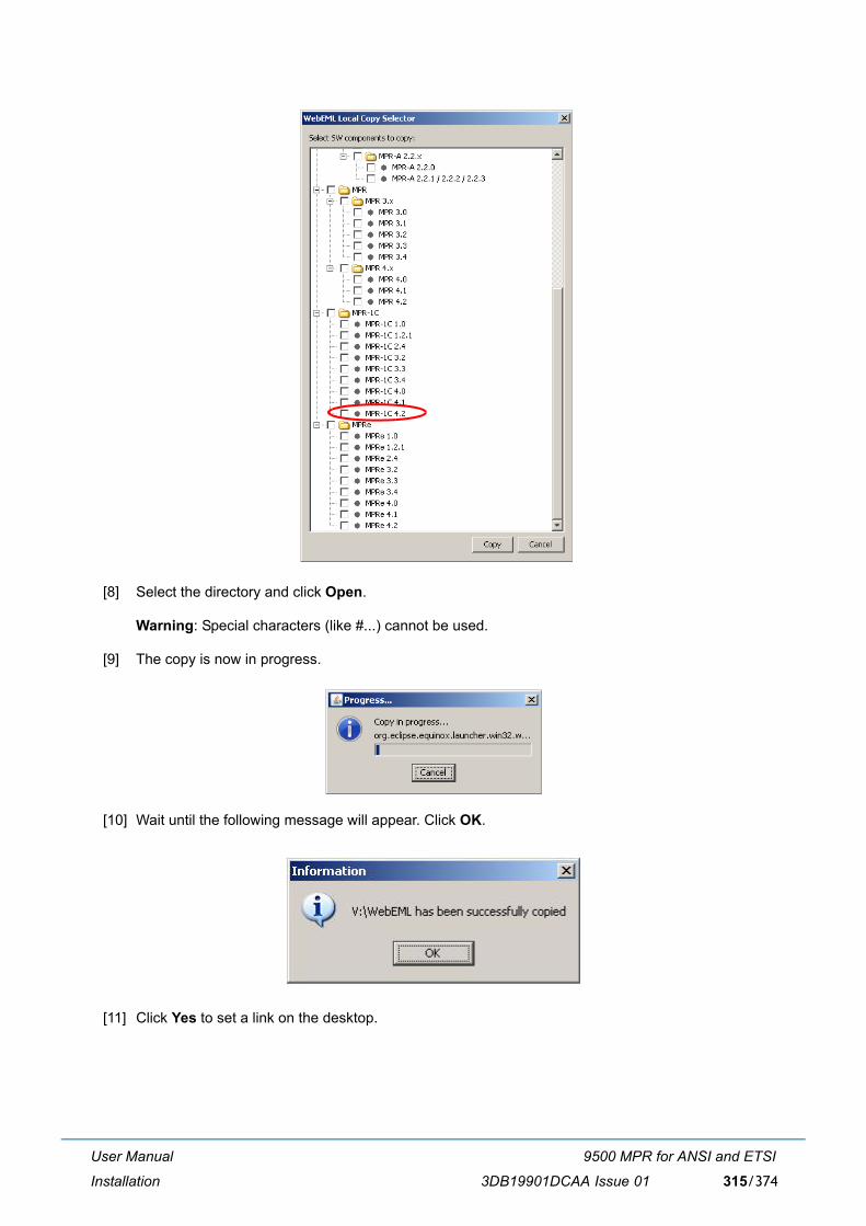
User Manual
Installation
9500 MPR for ANSI and ETSI
3DB19901DCAA Issue 01 315/374
[8] Select the directory and click Open.
Warning: Special characters (like #...) cannot be used.
[9] The copy is now in progress.
[10] Wait until the following message will appear. Click OK.
[11] Click Yes to set a link on the desktop.
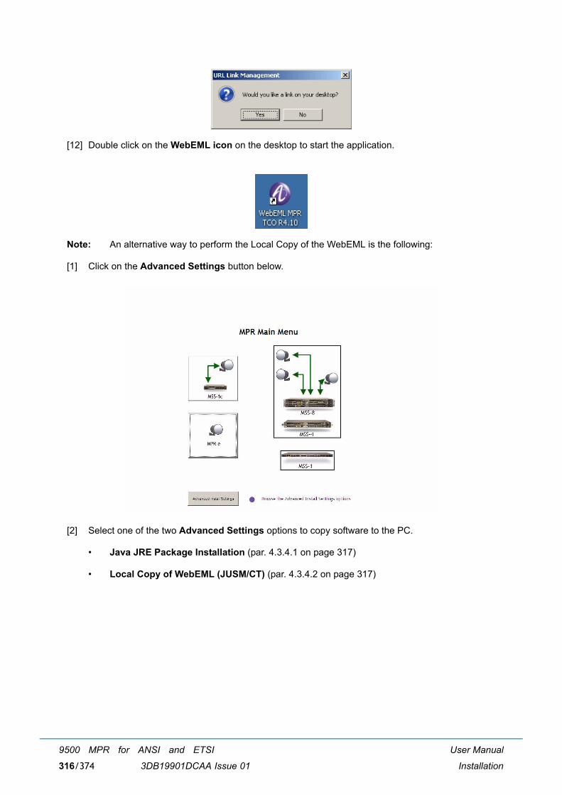
User Manual
Installation
9500 MPR for ANSI and ETSI
3DB19901DCAA Issue 01316/374
[12] Double click on the WebEML icon on the desktop to start the application.
Note: An alternative way to perform the Local Copy of the WebEML is the following:
[1] Click on the Advanced Settings button below.
[2] Select one of the two Advanced Settings options to copy software to the PC.
� Java JRE Package Installation (par. 4.3.4.1 on page 317)
� Local Copy of WebEML (JUSM/CT) (par. 4.3.4.2 on page 317)
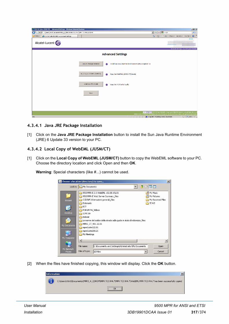
User Manual
Installation
9500 MPR for ANSI and ETSI
3DB19901DCAA Issue 01 317/374
4.3.4.1 Java JRE Package Installation
[1] Click on the Java JRE Package Installation button to install the Sun Java Runtime Environment(JRE) 6 Update 33 version to your PC.
4.3.4.2 Local Copy of WebEML (JUSM/CT)
[1] Click on the Local Copy of WebEML (JUSM/CT) button to copy the WebEML software to your PC.Choose the directory location and click Open and then OK.
Warning: Special characters (like #...) cannot be used.
[2] When the files have finished copying, this window will display. Click the OK button.
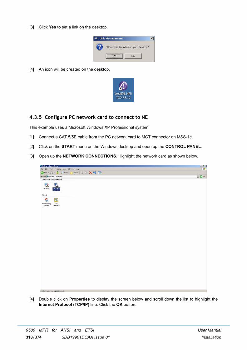
User Manual
Installation
9500 MPR for ANSI and ETSI
3DB19901DCAA Issue 01318/374
[3] Click Yes to set a link on the desktop.
[4] An icon will be created on the desktop.
4.3.5 Configure PC network card to connect to NE
This example uses a Microsoft Windows XP Professional system.
[1] Connect a CAT 5/5E cable from the PC network card to MCT connector on MSS-1c.
[2] Click on the START menu on the Windows desktop and open up the CONTROL PANEL.
[3] Open up the NETWORK CONNECTIONS. Highlight the network card as shown below.
[4] Double click on Properties to display the screen below and scroll down the list to highlight theInternet Protocol (TCP/IP) line. Click the OK button.
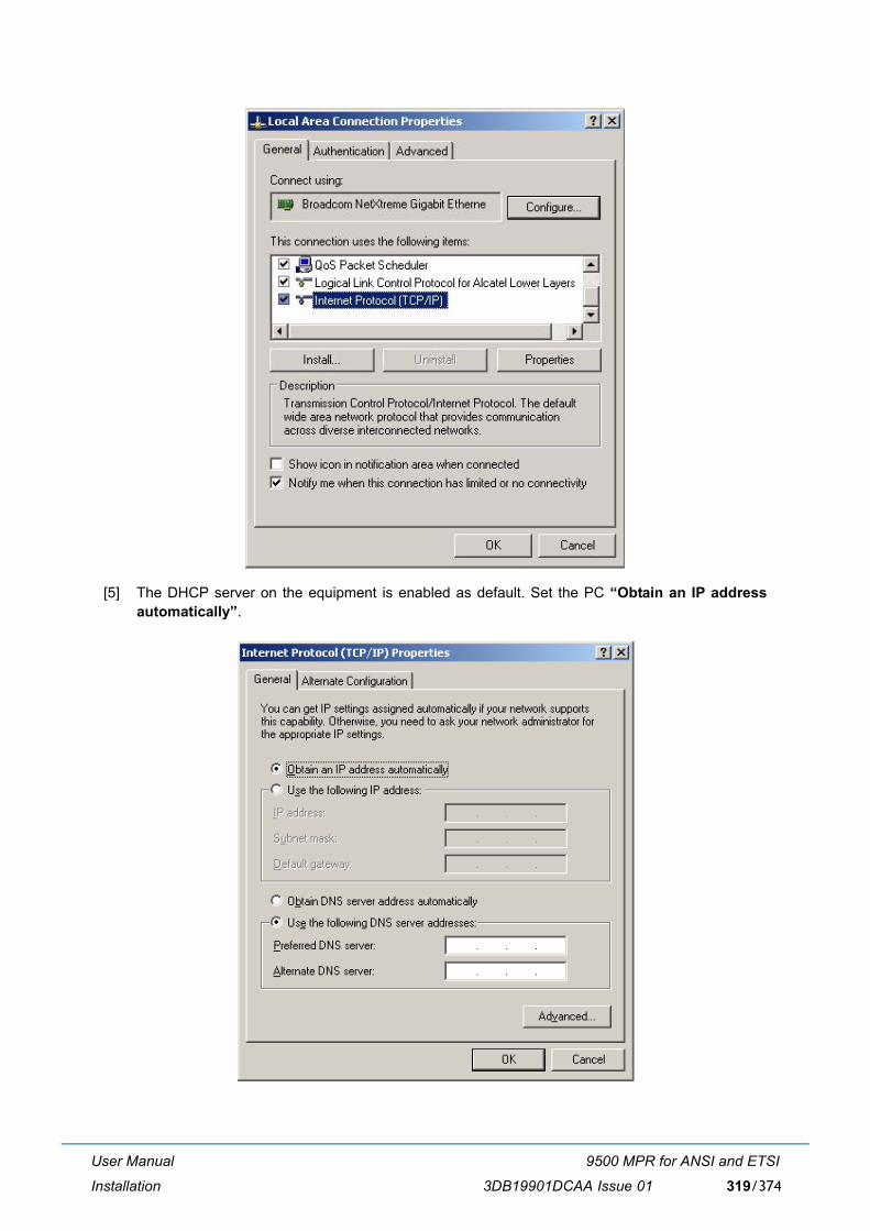
User Manual
Installation
9500 MPR for ANSI and ETSI
3DB19901DCAA Issue 01 319/374
[5] The DHCP server on the equipment is enabled as default. Set the PC �Obtain an IP addressautomatically�.

User Manual
Installation
9500 MPR for ANSI and ETSI
3DB19901DCAA Issue 01320/374
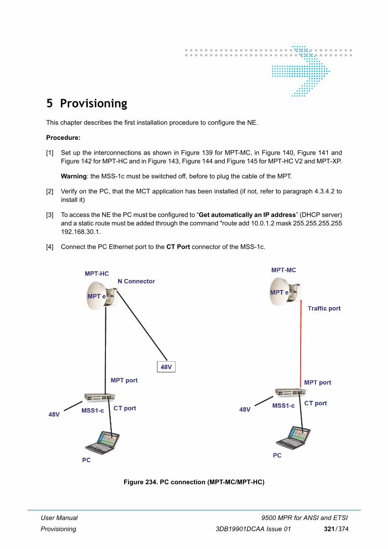
User Manual
Provisioning
9500 MPR for ANSI and ETSI
3DB19901DCAA Issue 01 321/374
5 ProvisioningThis chapter describes the first installation procedure to configure the NE.
Procedure:
[1] Set up the interconnections as shown in Figure 139 for MPT-MC, in Figure 140, Figure 141 andFigure 142 for MPT-HC and in Figure 143, Figure 144 and Figure 145 for MPT-HC V2 and MPT-XP.
Warning: the MSS-1c must be switched off, before to plug the cable of the MPT.
[2] Verify on the PC, that the MCT application has been installed (if not, refer to paragraph 4.3.4.2 toinstall it)
[3] To access the NE the PC must be configured to �Get automatically an IP address� (DHCP server)and a static route must be added through the command "route add 10.0.1.2 mask 255.255.255.255192.168.30.1.
[4] Connect the PC Ethernet port to the CT Port connector of the MSS-1c.
Figure 234. PC connection (MPT-MC/MPT-HC)
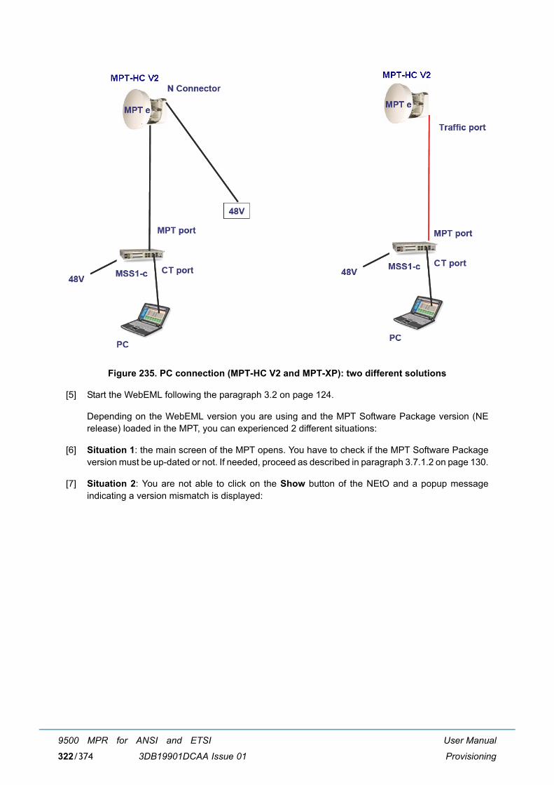
User Manual
Provisioning
9500 MPR for ANSI and ETSI
3DB19901DCAA Issue 01322/374
Figure 235. PC connection (MPT-HC V2 and MPT-XP): two different solutions
[5] Start the WebEML following the paragraph 3.2 on page 124.
Depending on the WebEML version you are using and the MPT Software Package version (NErelease) loaded in the MPT, you can experienced 2 different situations:
[6] Situation 1: the main screen of the MPT opens. You have to check if the MPT Software Packageversion must be up-dated or not. If needed, proceed as described in paragraph 3.7.1.2 on page 130.
[7] Situation 2: You are not able to click on the Show button of the NEtO and a popup messageindicating a version mismatch is displayed:
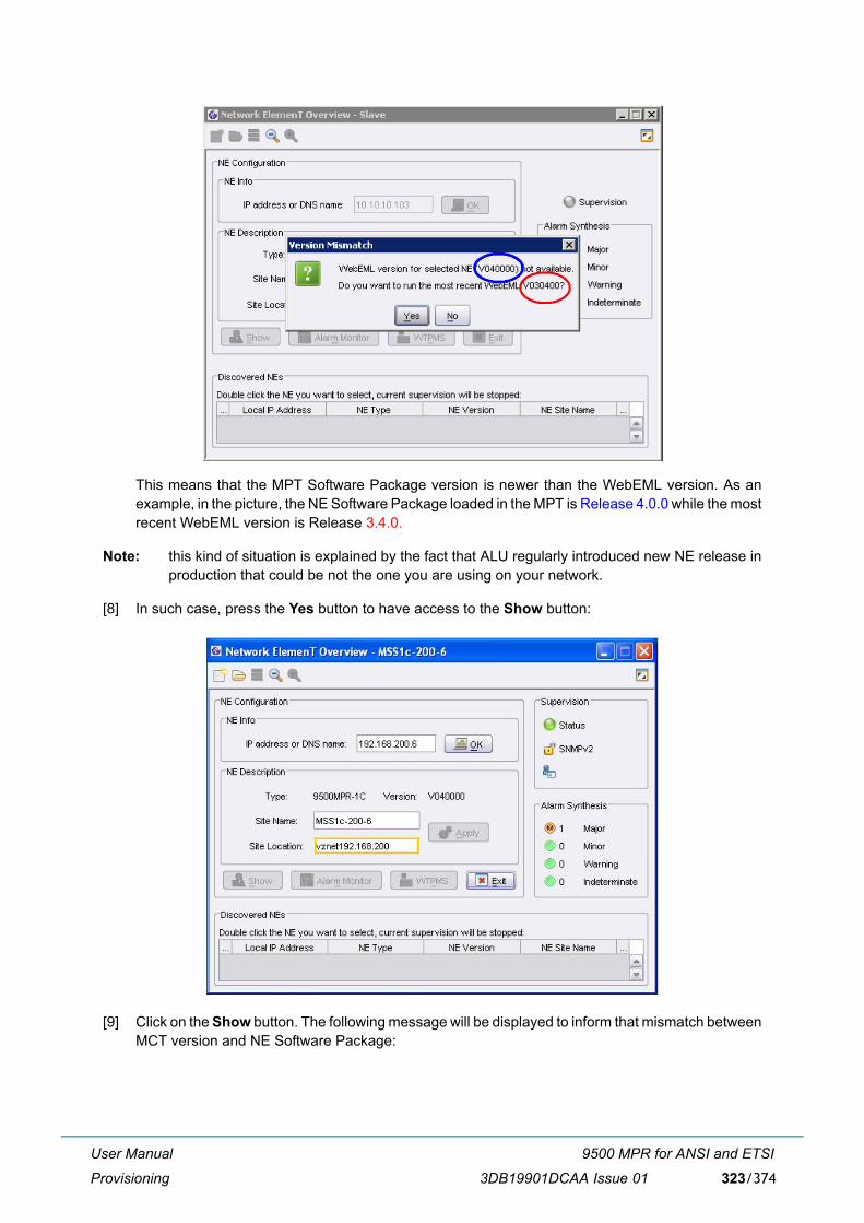
User Manual
Provisioning
9500 MPR for ANSI and ETSI
3DB19901DCAA Issue 01 323/374
This means that the MPT Software Package version is newer than the WebEML version. As anexample, in the picture, the NE Software Package loaded in the MPT is Release 4.0.0 while the mostrecent WebEML version is Release 3.4.0.
Note: this kind of situation is explained by the fact that ALU regularly introduced new NE release inproduction that could be not the one you are using on your network.
[8] In such case, press the Yes button to have access to the Show button:
[9] Click on the Show button. The following message will be displayed to inform that mismatch betweenMCT version and NE Software Package:
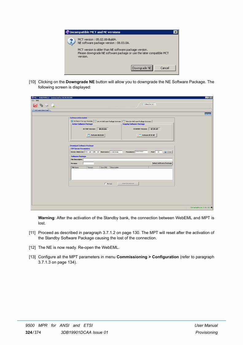
User Manual
Provisioning
9500 MPR for ANSI and ETSI
3DB19901DCAA Issue 01324/374
[10] Clicking on the Downgrade NE button will allow you to downgrade the NE Software Package. Thefollowing screen is displayed:
Warning: After the activation of the Standby bank, the connection between WebEML and MPT islost.
[11] Proceed as described in paragraph 3.7.1.2 on page 130. The MPT will reset after the activation ofthe Standby Software Package causing the lost of the connection.
[12] The NE is now ready. Re-open the WebEML.
[13] Configure all the MPT parameters in menu Commissioning > Configuration (refer to paragraph3.7.1.3 on page 134).

User Manual
Maintenance and Trouble-clearing
9500 MPR for ANSI and ETSI
3DB19901DCAA Issue 01 325/374
6 Maintenance and Trouble-clearing
6.1 Introduction
This section contains information and procedures to aid in restoring the equipment to its proper operatingcondition after it has been determined that a problem exists.
The following warnings and cautions apply while operating, performance testing, troubleshooting, orrepairing the 9500 MPR series radios.
Short circuits in low-voltage, low-impedance dc circuits can cause severe arcing that may result in burns or eye injury. Remove rings,
watches, and other metal jewelry while working with primary circuits. Exercise caution to avoid shorting power input terminals.
Units with the electrostatic-sensitive (ESS) symbol contain ESS devices. Store these units in an antistatic container when not in use, and anyone handling a unit should observe antistatic precautions.
Refer to the Special Precautions pages in the front of the instruction book for detailed handling information.
Note: Ensure that all antennas are properly aligned and waveguide is in good physical condition.
Before performing procedures that might in any way affect transmission, it is recommended that the person performing the procedure understand the Rules and Regulations pertaining to the equipment and be properly authorized to operate the equipment.
6.2 Maintenance philosophy
This section provides information and procedures for equipment maintenance down to the Card level.Card repair is not covered in this manual.

User Manual
Maintenance and Trouble-clearing
9500 MPR for ANSI and ETSI
3DB19901DCAA Issue 01326/374
The use of maintenance procedures in this section may result from failure of a periodic check, an alarmindication, or unacceptable performance.
6.3 Personal computer (PC)/laptop
Connect the RJ45 Interface cable between Craft Terminal connector on the Core-E Card and the PC.
6.4 Troubleshooting
This section provides guidance on:
� Before Going to Site Checklist
� Troubleshooting Basics
� Troubleshooting Path Problems
� Troubleshooting Configuration Problems
� Troubleshooting Ethernet Problems
� Troubleshooting TMN Problems
� Troubleshooting Network Supervision
6.4.1 Before going to site checklist
Where possible, before going to site obtain the following information:
� Does the fault require immediate attention?
� Determine who is the best-placed person to attend the fault.
� Confirm the nature and severity of the reported fault, its location, 9500 MPR type, frequency band,high/low end ODU, capacity modulation and configuration (nonprotected, protected, diversity). Ask:
� Is just one 9500 MPR link affected, or a number of links in the same geographical area?
� Is the path down completely or is traffic passing but with a BER alarm?
� Is only one or a number of tributaries affected?
� Could the fault be in the equipment connected to 9500 MPR, rather than in 9500 MPR? Arethere alarms on other, connected equipment?
� Is it a hard or intermittent fault?
� Do alarms confirm which end of an alarmed link is faulty?
� Could the weather (rain, ice, high wind, temperature) be a factor in the reported fault?
Note: If the fault suggests a rain fade or other weather related fade condition and it matches the prevailing weather conditions, do not take any action until the weather abates.
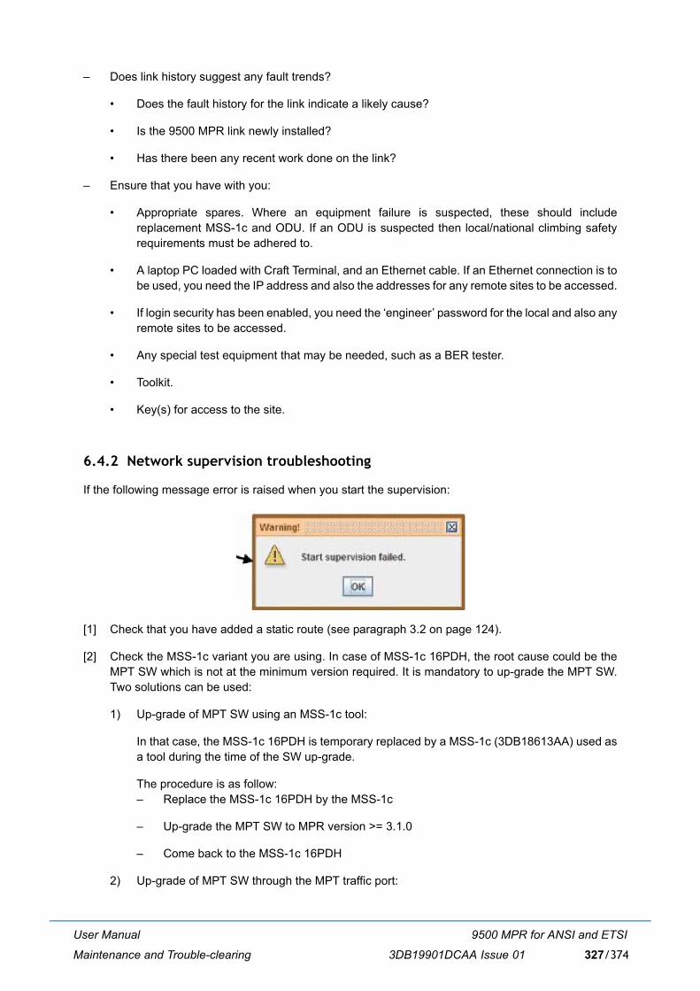
User Manual
Maintenance and Trouble-clearing
9500 MPR for ANSI and ETSI
3DB19901DCAA Issue 01 327/374
� Does link history suggest any fault trends?
� Does the fault history for the link indicate a likely cause?
� Is the 9500 MPR link newly installed?
� Has there been any recent work done on the link?
� Ensure that you have with you:
� Appropriate spares. Where an equipment failure is suspected, these should includereplacement MSS-1c and ODU. If an ODU is suspected then local/national climbing safetyrequirements must be adhered to.
� A laptop PC loaded with Craft Terminal, and an Ethernet cable. If an Ethernet connection is tobe used, you need the IP address and also the addresses for any remote sites to be accessed.
� If login security has been enabled, you need the �engineer� password for the local and also anyremote sites to be accessed.
� Any special test equipment that may be needed, such as a BER tester.
� Toolkit.
� Key(s) for access to the site.
6.4.2 Network supervision troubleshooting
If the following message error is raised when you start the supervision:
[1] Check that you have added a static route (see paragraph 3.2 on page 124).
[2] Check the MSS-1c variant you are using. In case of MSS-1c 16PDH, the root cause could be theMPT SW which is not at the minimum version required. It is mandatory to up-grade the MPT SW.Two solutions can be used:
1) Up-grade of MPT SW using an MSS-1c tool:
In that case, the MSS-1c 16PDH is temporary replaced by a MSS-1c (3DB18613AA) used asa tool during the time of the SW up-grade.
The procedure is as follow:� Replace the MSS-1c 16PDH by the MSS-1c
� Up-grade the MPT SW to MPR version >= 3.1.0
� Come back to the MSS-1c 16PDH
2) Up-grade of MPT SW through the MPT traffic port:
User Manual
Maintenance and Trouble-clearing
9500 MPR for ANSI and ETSI
3DB19901DCAA Issue 01328/374
The procedure consists to connect directly the PC on the MPT electrical traffic port as describedin the User Manual MPR-e R3.3.0 (3DB18884EAAA).
The PC must have a GbE interface and capability to tag VLAN. Depending on the MPT typeand the connection between MSS-1c 16PDH and MPT (electrical or optical), additionalmaterials may be needed as follow:
� MPT-MC:
� a Power Injector box (3CC50129AA) must be used as a tool to merge the data fromthe PC and the DC. This composite signal is sent to the MPT-MC
� a RJ45/RJ45 cable to connect the PC to the Power injector box.
� MPT-HC v1:
� a RJ45/RJ45 cable to connect the PC to the MPT electrical traffic port� a Power Extractor (3CC50107AA) to insert between the MPT1 electrical port of the
MSS-1c 16PDH and the N connector of MPT-HC v1 (the RJ45 connector "Data Out"of the Power Extractor is not used).
� MPT-HC v2:
� a Power Injector box (3CC50129AA) or MPT Extended Power Unit (3CC50174AA)must be used as a tool to merge the data from the PC and the DC. This compositesignal is sent to the MPT--HC v2
� a RJ45/RJ45 cable to connect the PC to the Power injector box.
� MPT-XP:
� an MPT Extended Power Unit (3CC50174AA) must be used as a tool to merge thedata from the PC and the DC. This composite signal is sent to the MPT--XP
� a RJ45/RJ45 cable to connect the PC to the MPT Extended Power Unit.
6.4.3 Troubleshooting basics
This section provides general guidance the equipment troubleshooting:
� Check front-panel LED indications. These provide summary alarm indications, which can helpnarrow down the location and type of failure. Refer to Operation section for details.
� Check the MCT Screen. When logging to the equipment with Craft Terminal, the opening screenis the Main Screen. Use the information provided in menu Alarms and in menu Events to check forseverity and problem type. Refer to Table 66., Table 67., Table 68., Table 69. and Table 70. for probable cause andrecommended action.
� Check the basics first.
� For example, if multiple alarms are present, and these include power supply voltage orhardware alarms, always check their cause before looking at resultant down-stream path failureor path warning (signal) alarms.
� Similarly, if a path-related failure is indicated (no hardware or software alarms), investigate thepath. Go to the Craft Terminal History screen (15 minute view) to check supporting data, suchas low RSL and incidence of intermittent pre-failure BER alarms, which if present are evidenceof a path-related failure.
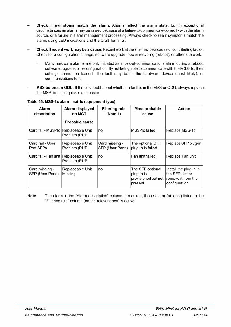
User Manual
Maintenance and Trouble-clearing
9500 MPR for ANSI and ETSI
3DB19901DCAA Issue 01 329/374
� Check if symptoms match the alarm. Alarms reflect the alarm state, but in exceptionalcircumstances an alarm may be raised because of a failure to communicate correctly with the alarmsource, or a failure in alarm management processing. Always check to see if symptoms match thealarm, using LED indications and the Craft Terminal.
� Check if recent work may be a cause. Recent work at the site may be a cause or contributing factor.Check for a configuration change, software upgrade, power recycling (reboot), or other site work:
� Many hardware alarms are only initiated as a loss-of-communications alarm during a reboot,software upgrade, or reconfiguration. By not being able to communicate with the MSS-1c, theirsettings cannot be loaded. The fault may be at the hardware device (most likely), orcommunications to it.
� MSS before an ODU. If there is doubt about whether a fault is in the MSS or ODU, always replacethe MSS first; it is quicker and easier.
Table 66. MSS-1c alarm matrix (equipment type)
Note: The alarm in the �Alarm description� column is masked, if one alarm (at least) listed in the�Filtering rule� column (on the relevant row) is active.
Alarm description
Alarm displayed on MCT
Filtering rule (Note 1)
Most probable cause
Action
Probable cause
Card fail - MSS-1c Replaceable Unit Problem (RUP)
no MSS-1c failed Replace MSS-1c
Card fail - User Port SFPs
Replaceable Unit Problem (RUP)
Card missing - SFP (User Ports)
The optional SFP plug-in is failed
Replace SFP plug-in
Card fail - Fan unit Replaceable Unit Problem (RUP)
no Fan unit failed Replace Fan unit
Card missing - SFP (User Ports)
Replaceable Unit Missing
no The SFP optional plug-in is provisioned but not present
Install the plug-in in the SFP slot or remove it from the configuration
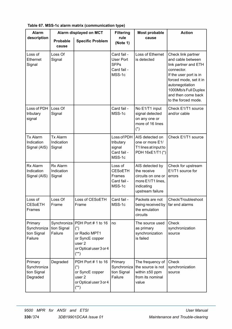
User Manual
Maintenance and Trouble-clearing
9500 MPR for ANSI and ETSI
3DB19901DCAA Issue 01330/374
Table 67. MSS-1c alarm matrix (communication type)
Alarm description
Alarm displayed on MCT Filtering rule
(Note 1)
Most probable cause
Action
Probable cause
Specific Problem
Loss of Ethernet Signal
Loss Of Signal
Card fail - User Port SFPsCard fail - MSS-1c
Loss of Ethernet is detected
Check link partner and cable between link partner and ETH connector.If the user port is in forced mode, set it in autonegotiation 1000Mb/s Full Duplex and then come back to the forced mode.
Loss of PDH tributary signal
Loss Of Signal
Card fail - MSS-1c
No E1/T1 input signal detected on any one or more of 16 lines (*)
Check E1/T1 source and/or cable
Tx Alarm Indication Signal (AIS)
Tx Alarm Indication Signal
Loss of PDH tributary signalCard fail - MSS-1c
AIS detected on one or more E1/T1 lines at input to PDH 16xE1/T1 (*)
Check E1/T1 source
Rx Alarm Indication Signal (AIS)
Rx Alarm Indication Signal
Loss of CESoETH FramesCard fail - MSS-1c
AIS detected by the receive circuits on one or more E1/T1 lines, indicating upstream failure
Check for upstream E1/T1 source for errors
Loss of CESoETH Frames
Loss Of Frame
Loss of CESoETH Frame
Card fail - MSS-1c
Packets are not being received by the emulation circuits
Check/Troubleshoot far end alarms
Primary Synchronization Signal Failure
Synchronization Signal Failure
PDH Port # 1 to 16 (*)or Radio MPT1or SyncE copper user 2or Optical user 3 or 4 (**)
no The source used as primary synchronization is failed
Check synchronization source
Primary Synchronization Signal Degraded
Degraded PDH Port # 1 to 16 (*)or SyncE copper user 2or Optical user 3 or 4 (**)
Primary Synchronization Signal Failure
The frequency of the source is not within ±50 ppm from its nominal value
Check synchronization source
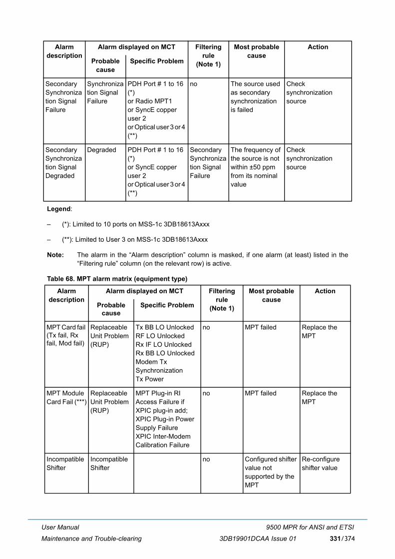
User Manual
Maintenance and Trouble-clearing
9500 MPR for ANSI and ETSI
3DB19901DCAA Issue 01 331/374
Legend:
� (*): Limited to 10 ports on MSS-1c 3DB18613Axxx
� (**): Limited to User 3 on MSS-1c 3DB18613Axxx
Note: The alarm in the �Alarm description� column is masked, if one alarm (at least) listed in the�Filtering rule� column (on the relevant row) is active.
Table 68. MPT alarm matrix (equipment type)
Secondary Synchronization Signal Failure
Synchronization Signal Failure
PDH Port # 1 to 16 (*)or Radio MPT1or SyncE copper user 2or Optical user 3 or 4 (**)
no The source used as secondary synchronization is failed
Check synchronization source
Secondary Synchronization Signal Degraded
Degraded PDH Port # 1 to 16 (*)or SyncE copper user 2or Optical user 3 or 4 (**)
Secondary Synchronization Signal Failure
The frequency of the source is not within ±50 ppm from its nominal value
Check synchronization source
Alarm description
Alarm displayed on MCT Filtering rule
(Note 1)
Most probable cause
Action
Probable cause
Specific Problem
MPT Card fail (Tx fail, Rx fail, Mod fail)
Replaceable Unit Problem (RUP)
Tx BB LO UnlockedRF LO UnlockedRx IF LO UnlockedRx BB LO UnlockedModem Tx SynchronizationTx Power
no MPT failed Replace the MPT
MPT Module Card Fail (***)
Replaceable Unit Problem (RUP)
MPT Plug-in RI Access Failure if XPIC plug-in add;XPIC Plug-in Power Supply FailureXPIC Inter-Modem Calibration Failure
no MPT failed Replace the MPT
Incompatible Shifter
Incompatible Shifter
no Configured shifter value not supported by the MPT
Re-configure shifter value
Alarm description
Alarm displayed on MCT Filtering rule
(Note 1)
Most probable cause
Action
Probable cause
Specific Problem
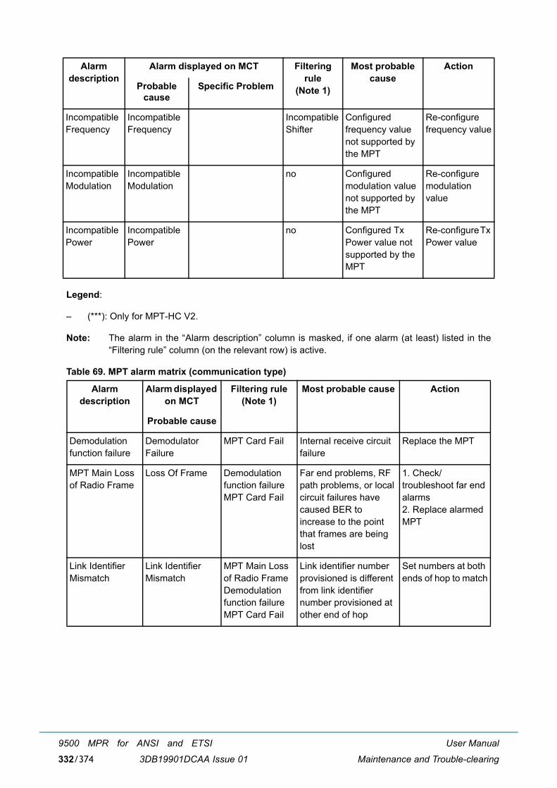
User Manual
Maintenance and Trouble-clearing
9500 MPR for ANSI and ETSI
3DB19901DCAA Issue 01332/374
Legend:
� (***): Only for MPT-HC V2.
Note: The alarm in the �Alarm description� column is masked, if one alarm (at least) listed in the�Filtering rule� column (on the relevant row) is active.
Table 69. MPT alarm matrix (communication type)
Incompatible Frequency
Incompatible Frequency
Incompatible Shifter
Configured frequency value not supported by the MPT
Re-configure frequency value
Incompatible Modulation
Incompatible Modulation
no Configured modulation value not supported by the MPT
Re-configure modulation value
Incompatible Power
Incompatible Power
no Configured Tx Power value not supported by the MPT
Re-configure Tx Power value
Alarm description
Alarm displayed on MCT
Filtering rule (Note 1)
Most probable cause Action
Probable cause
Demodulation function failure
Demodulator Failure
MPT Card Fail Internal receive circuit failure
Replace the MPT
MPT Main Loss of Radio Frame
Loss Of Frame Demodulation function failureMPT Card Fail
Far end problems, RF path problems, or local circuit failures have caused BER to increase to the point that frames are being lost
1. Check/troubleshoot far end alarms2. Replace alarmed MPT
Link Identifier Mismatch
Link Identifier Mismatch
MPT Main Loss of Radio Frame Demodulation function failure MPT Card Fail
Link identifier number provisioned is different from link identifier number provisioned at other end of hop
Set numbers at both ends of hop to match
Alarm description
Alarm displayed on MCT Filtering rule
(Note 1)
Most probable cause
Action
Probable cause
Specific Problem

User Manual
Maintenance and Trouble-clearing
9500 MPR for ANSI and ETSI
3DB19901DCAA Issue 01 333/374
Note: The alarm in the �Alarm description� column is masked, if one alarm (at least) listed in the�Filtering rule� column (on the relevant row) is active.
High BER (HBER)
High BER Demodulation function failureMPT Main Loss of Radio FrameLink Identifier MismatchMPT Card Fail
Bit Error Rate threshold (10E-4) exceeded
1. Verify RF path is clear, antenna is aligned, and no existing weather-related problems2. Verify RSL is above RCV threshold. If not � check upstream transmitter output/troubleshoot transmitter
Early Warning (EW)
Early Warning HBERDemodulation function failureMPT Main Loss of Radio FrameLink Identifier MismatchMPT Card Fail
10E-9 BER detected No action is required at this time. Monitor receive signal for increased degrading
MPT Main Communication Loop
Loop Problem no Communication problem between the local MPT and the remote MPT for all the functionalities requiring a communication loop (ATPC or ACM)
Check the radio hop
ANSI_ATPC_TimeOut
Atpc High Power Timeout
no Alarm only managed in ANSI mode and raised when Tx power level is at ATPC max level during 5 consecutive minutes
Check the radio hop
PPP fail PPP Failure no 1) PPP RF channel not enabled in both stations of the radio link 2) Restart of remote MPT on-going (following a SW Download operation)3) Radio path broken
1) Verify PPP RF enabled2) Wait MPT restart finalization3) Verify the RF path
Alarm description
Alarm displayed on MCT
Filtering rule (Note 1)
Most probable cause Action
Probable cause
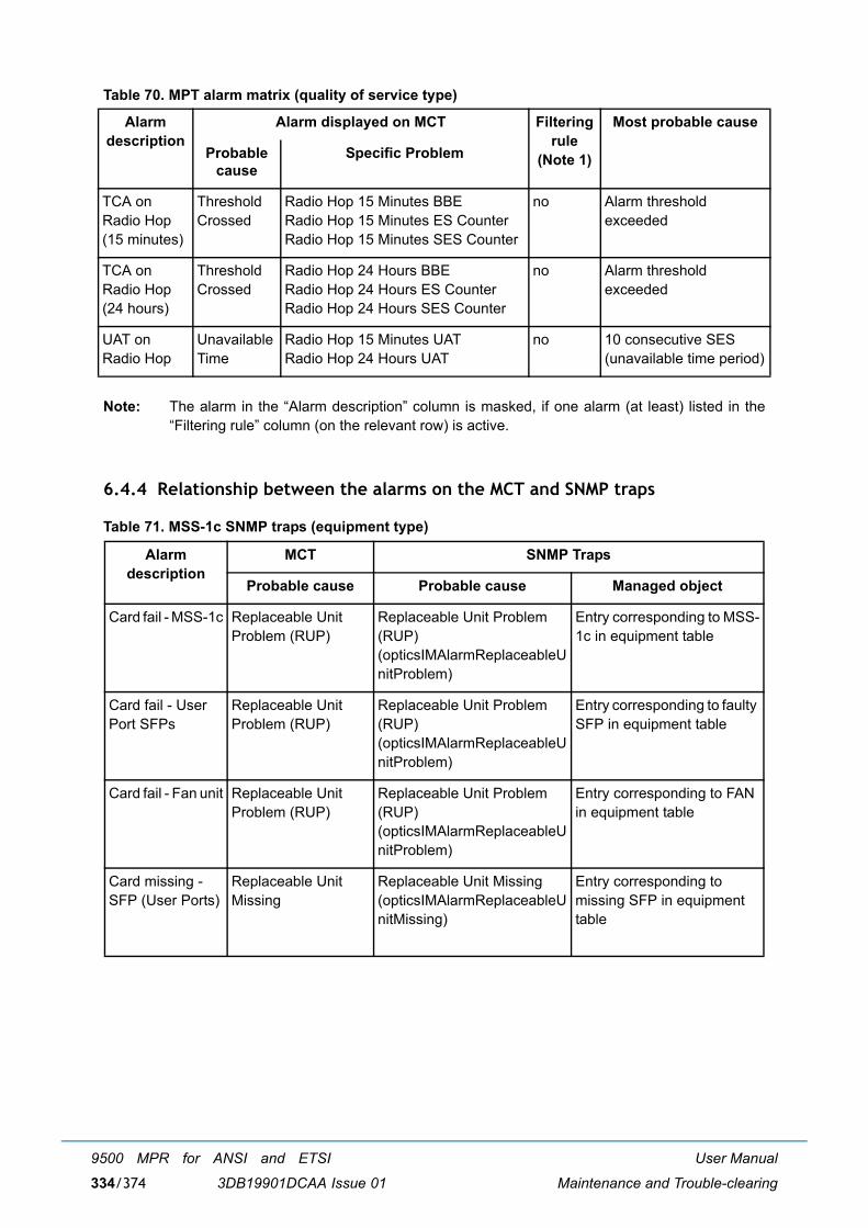
User Manual
Maintenance and Trouble-clearing
9500 MPR for ANSI and ETSI
3DB19901DCAA Issue 01334/374
Table 70. MPT alarm matrix (quality of service type)
Note: The alarm in the �Alarm description� column is masked, if one alarm (at least) listed in the�Filtering rule� column (on the relevant row) is active.
6.4.4 Relationship between the alarms on the MCT and SNMP traps
Table 71. MSS-1c SNMP traps (equipment type)
Alarm description
Alarm displayed on MCT Filtering rule
(Note 1)
Most probable cause
Probable cause
Specific Problem
TCA on Radio Hop (15 minutes)
Threshold Crossed
Radio Hop 15 Minutes BBERadio Hop 15 Minutes ES CounterRadio Hop 15 Minutes SES Counter
no Alarm threshold exceeded
TCA on Radio Hop (24 hours)
Threshold Crossed
Radio Hop 24 Hours BBERadio Hop 24 Hours ES CounterRadio Hop 24 Hours SES Counter
no Alarm threshold exceeded
UAT on Radio Hop
Unavailable Time
Radio Hop 15 Minutes UATRadio Hop 24 Hours UAT
no 10 consecutive SES (unavailable time period)
Alarm description
MCT SNMP Traps
Probable cause Probable cause Managed object
Card fail - MSS-1c Replaceable Unit Problem (RUP)
Replaceable Unit Problem (RUP) (opticsIMAlarmReplaceableUnitProblem)
Entry corresponding to MSS-1c in equipment table
Card fail - User Port SFPs
Replaceable Unit Problem (RUP)
Replaceable Unit Problem (RUP) (opticsIMAlarmReplaceableUnitProblem)
Entry corresponding to faulty SFP in equipment table
Card fail - Fan unit Replaceable Unit Problem (RUP)
Replaceable Unit Problem (RUP) (opticsIMAlarmReplaceableUnitProblem)
Entry corresponding to FAN in equipment table
Card missing - SFP (User Ports)
Replaceable Unit Missing
Replaceable Unit Missing (opticsIMAlarmReplaceableUnitMissing)
Entry corresponding to missing SFP in equipment table
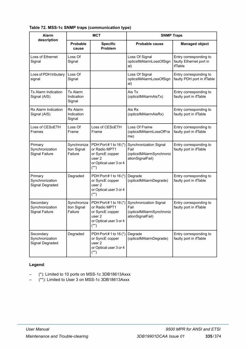
User Manual
Maintenance and Trouble-clearing
9500 MPR for ANSI and ETSI
3DB19901DCAA Issue 01 335/374
Table 72. MSS-1c SNMP traps (communication type)
Legend:
� (*): Limited to 10 ports on MSS-1c 3DB18613Axxx � (**): Limited to User 3 on MSS-1c 3DB18613Axxx
Alarm description
MCT SNMP Traps
Probable cause
Specific Problem
Probable cause Managed object
Loss of Ethernet Signal
Loss Of Signal
Loss Of Signal opticsIMAlarmLossOfSignal)
Entry corresponding to faulty Ethernet port in ifTable
Loss of PDH tributary signal
Loss Of Signal
Loss Of SignalopticsIMAlarmLossOfSignal)
Entry corresponding to faulty PDH port in ifTable
Tx Alarm Indication Signal (AIS)
Tx Alarm Indication Signal
Ais Tx(opticsIMAlarmAisTx)
Entry corresponding to faulty port in ifTable
Rx Alarm Indication Signal (AIS)
Rx Alarm Indication Signal
Ais Rx(opticsIMAlarmAisRx)
Entry corresponding to faulty port in ifTable
Loss of CESoETH Frames
Loss Of Frame
Loss of CESoETH Frame
Loss Of Frame(opticsIMAlarmLossOfFrame)
Entry corresponding to faulty port in ifTable
Primary Synchronization Signal Failure
Synchronization Signal Failure
PDH Port # 1 to 16 (*)or Radio MPT1or SyncE copper user 2or Optical user 3 or 4 (**)
Synchronization Signal Fail(opticsIMAlarmSynchronizationSignalFail)
Entry corresponding to faulty port in ifTable
Primary Synchronization Signal Degraded
Degraded PDH Port # 1 to 16 (*)or SyncE copper user 2or Optical user 3 or 4 (**)
Degrade(opticsIMAlarmDegrade)
Entry corresponding to faulty port in ifTable
Secondary Synchronization Signal Failure
Synchronization Signal Failure
PDH Port # 1 to 16 (*)or Radio MPT1or SyncE copper user 2or Optical user 3 or 4 (**)
Synchronization Signal Fail(opticsIMAlarmSynchronizationSignalFail)
Entry corresponding to faulty port in ifTable
Secondary Synchronization Signal Degraded
Degraded PDH Port # 1 to 16 (*)or SyncE copper user 2or Optical user 3 or 4 (**)
Degrade(opticsIMAlarmDegrade)
Entry corresponding to faulty port in ifTable
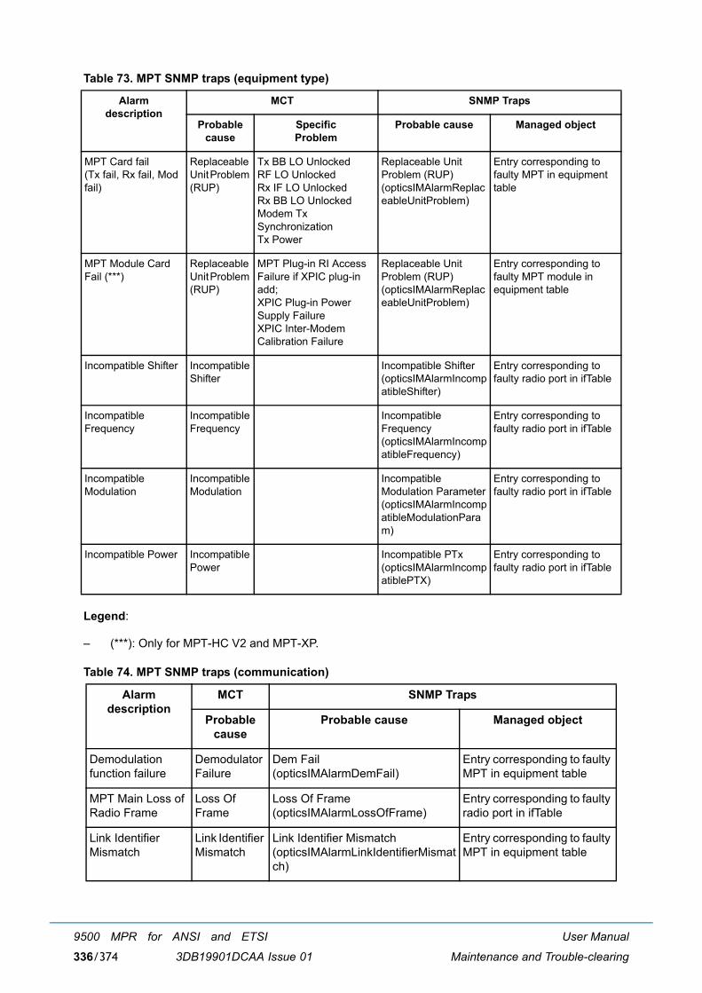
User Manual
Maintenance and Trouble-clearing
9500 MPR for ANSI and ETSI
3DB19901DCAA Issue 01336/374
Table 73. MPT SNMP traps (equipment type)
Legend:
� (***): Only for MPT-HC V2 and MPT-XP.
Table 74. MPT SNMP traps (communication)
Alarm description
MCT SNMP Traps
Probable cause
Specific Problem
Probable cause Managed object
MPT Card fail(Tx fail, Rx fail, Mod fail)
Replaceable Unit Problem (RUP)
Tx BB LO UnlockedRF LO UnlockedRx IF LO UnlockedRx BB LO UnlockedModem Tx SynchronizationTx Power
Replaceable Unit Problem (RUP)(opticsIMAlarmReplaceableUnitProblem)
Entry corresponding to faulty MPT in equipment table
MPT Module Card Fail (***)
Replaceable Unit Problem (RUP)
MPT Plug-in RI Access Failure if XPIC plug-in add; XPIC Plug-in Power Supply FailureXPIC Inter-Modem Calibration Failure
Replaceable Unit Problem (RUP)(opticsIMAlarmReplaceableUnitProblem)
Entry corresponding to faulty MPT module in equipment table
Incompatible Shifter Incompatible Shifter
Incompatible Shifter(opticsIMAlarmIncompatibleShifter)
Entry corresponding to faulty radio port in ifTable
Incompatible Frequency
Incompatible Frequency
Incompatible Frequency(opticsIMAlarmIncompatibleFrequency)
Entry corresponding to faulty radio port in ifTable
Incompatible Modulation
Incompatible Modulation
Incompatible Modulation Parameter(opticsIMAlarmIncompatibleModulationParam)
Entry corresponding to faulty radio port in ifTable
Incompatible Power Incompatible Power
Incompatible PTx(opticsIMAlarmIncompatiblePTX)
Entry corresponding to faulty radio port in ifTable
Alarm description
MCT SNMP Traps
Probable cause
Probable cause Managed object
Demodulation function failure
Demodulator Failure
Dem Fail(opticsIMAlarmDemFail)
Entry corresponding to faulty MPT in equipment table
MPT Main Loss of Radio Frame
Loss Of Frame
Loss Of Frame(opticsIMAlarmLossOfFrame)
Entry corresponding to faulty radio port in ifTable
Link Identifier Mismatch
Link Identifier Mismatch
Link Identifier Mismatch(opticsIMAlarmLinkIdentifierMismatch)
Entry corresponding to faulty MPT in equipment table
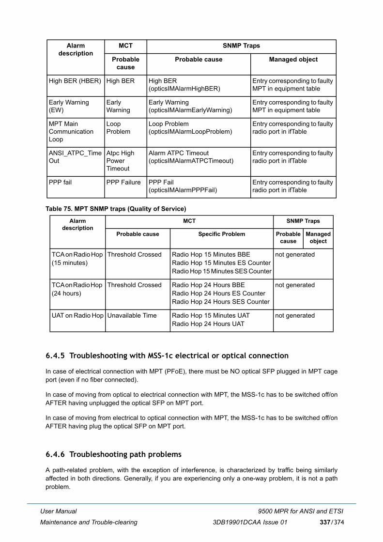
User Manual
Maintenance and Trouble-clearing
9500 MPR for ANSI and ETSI
3DB19901DCAA Issue 01 337/374
Table 75. MPT SNMP traps (Quality of Service)
6.4.5 Troubleshooting with MSS-1c electrical or optical connection
In case of electrical connection with MPT (PFoE), there must be NO optical SFP plugged in MPT cageport (even if no fiber connected).
In case of moving from optical to electrical connection with MPT, the MSS-1c has to be switched off/onAFTER having unplugged the optical SFP on MPT port.
In case of moving from electrical to optical connection with MPT, the MSS-1c has to be switched off/onAFTER having plug the optical SFP on MPT port.
6.4.6 Troubleshooting path problems
A path-related problem, with the exception of interference, is characterized by traffic being similarlyaffected in both directions. Generally, if you are experiencing only a one-way problem, it is not a pathproblem.
High BER (HBER) High BER High BER(opticsIMAlarmHighBER)
Entry corresponding to faulty MPT in equipment table
Early Warning (EW)
Early Warning
Early Warning(opticsIMAlarmEarlyWarning)
Entry corresponding to faulty MPT in equipment table
MPT Main Communication Loop
Loop Problem
Loop Problem(opticsIMAlarmLoopProblem)
Entry corresponding to faulty radio port in ifTable
ANSI_ATPC_TimeOut
Atpc High Power Timeout
Alarm ATPC Timeout(opticsIMAlarmATPCTimeout)
Entry corresponding to faulty radio port in ifTable
PPP fail PPP Failure PPP Fail(opticsIMAlarmPPPFail)
Entry corresponding to faulty radio port in ifTable
Alarm description
MCT SNMP Traps
Probable cause Specific Problem Probable cause
Managed object
TCA on Radio Hop (15 minutes)
Threshold Crossed Radio Hop 15 Minutes BBERadio Hop 15 Minutes ES CounterRadio Hop 15 Minutes SES Counter
not generated
TCA on Radio Hop (24 hours)
Threshold Crossed Radio Hop 24 Hours BBERadio Hop 24 Hours ES CounterRadio Hop 24 Hours SES Counter
not generated
UAT on Radio Hop Unavailable Time Radio Hop 15 Minutes UATRadio Hop 24 Hours UAT
not generated
Alarm description
MCT SNMP Traps
Probable cause
Probable cause Managed object

User Manual
Maintenance and Trouble-clearing
9500 MPR for ANSI and ETSI
3DB19901DCAA Issue 01338/374
Note: A path extends from ODU antenna port to ODU antenna port.
� Normally a path problem is signalled by a reduced RSL, and depending on its severity, a high BER.
� Only in worst case situations, such as an antenna knocked out of alignment, will a path failcompletely, and stay that way.
� For weather-related problems, such as rain or ducting, the path problem will disappear as theweather returns to normal.
6.4.6.1 Path problems on a commissioned link
A path problem on an existing link, one that has been operating satisfactorily may be caused by:
� Weather-related path degradation
If BER alarms are fleeting/not permanent and RSL returns to its normal, commissioned level afterthe alarm is cleared, rain, diffraction, or multipath fading is indicated. Rain fade is the likely causeof fade for links 13 GHz and higher. Diffraction and multipath/ducting for links 11 GHz and lower. Ifthese alarms are persistent, there could be a problem with the link design or original installation.
� Changed antenna alignment or antenna feed problem
If RSLs do not return to commissioned levels after a period of exceptionally strong winds, suspectantenna alignment. Also, check the antenna for physical damage, such as may occur with ice-fall.For a remote-mounted ODU, check its antenna feeder.
� New path obstruction
Where all other parameters check as normal, and the path has potential for it to be obstructed byconstruction works, view/survey the path for possible new obstructions.
� Interference from other signal sources
Interference usually affects traffic in just one direction. Unlike other path problems, RSL is notaffected. If suspected, check for new link installations at, or in the same geographical area, as theaffected site. Ultimately, a spectrum analyzer may have to be used to confirm interference, which isnot an easy task given the need to connect directly to the antenna port, after removing the ODU.
6.4.6.2 Path problems on a new link
For a new link, potential problems can extend to also include:
� Incorrect antenna alignment
One or both antennas incorrectly aligned. Refer to Installation alignment procedure on CD.
� Mismatching antenna polarizations
Given a typical polarization discrimination of 30 dB, for most links it is not possible to capture a signalto begin the antenna alignment process.
� Incorrect path calculations
If the RSLs are too low or too high, antenna alignment is correct, and Tx power settings are correct,check the path calculations used to determine the link performance. A good calculation match is +/- 2 dB. Disagreements in excess of 3 dB should be investigated.
� Reflections
User Manual
Maintenance and Trouble-clearing
9500 MPR for ANSI and ETSI
3DB19901DCAA Issue 01 339/374
Reflection (path cancellation) problems may not have been picked up at the path planning stage,particularly if the survey was a simple line-of-sight. If suspected, resurvey the path.
6.4.7 Troubleshooting configuration problems
Configuration problems should only occur during the setup of a new link, or reconfiguration of an existinglink. The more common problems may be broadly categorized as:
� Incorrect circuit connections
No alarms are activated for incorrect circuit connections. An incorrect assignment means theexpected end-to-end circuit connectivity will not happen. Re-check circuit assignments for all nodescarrying the lost circuit(s).Take extra care when configuring ring circuits.
� Incorrect ID naming and commissioning
All traffic-carrying circuits must have a unique flow ID for the cross-connect capability to operate.
� Incorrect/incompatible trib settings
Trib line interface settings incorrect, or line levels incompatible. While no alarm activates for anincorrect setting, its effect may result in line levels being too low (LOS alarm), or too high, resultingin a high BER.
6.4.8 Troubleshooting ethernet problems
This section gives general guidance on troubleshooting problems related to the four Ethernet ports on theMSS-1c.
The most common Ethernet problems are network and connectivity related and therefore always checkthe following first:
� for User and NMS ports, verify link partner capability, provisioning, and connection
� for Radio ports, verify the cabling between MPT and MSS-1c
In order for the green Link LED to light:
1) Cable must be connected to Ethernet port
2) Ethernet port must be enabled (provisioned Enabled). Applicable for User and NMS ports
3) Speed and mode must be provisioned the same as the link partner.
The yellow LED opposite the green on the connector indicates activity only. The flashing yellow LED isnot an indicator of signal type or quality.
6.4.9 Troubleshooting TMN problems
This section gives general guidance on troubleshooting TMN problems related to NMS Ethernet ports 1and 2 on the MSS-1c.

User Manual
Maintenance and Trouble-clearing
9500 MPR for ANSI and ETSI
3DB19901DCAA Issue 01340/374
The most common TMN problems are network related and first alert is normally observed by improperoperation at the SNMP master. Always check the following first:
� Verify master is properly registered in NE to receive traps.
� Verify SNMP version matches system requirements
� Verify correct community string and privileges
� Verify proper network routing.
Refer to Table 76. for detail TMN network troubleshooting.
Table 76. TMN network troubleshooting
Problem Possible Cause Possible Solution
Unusually slow communicationin radio network
1. Normal network managementtraffic is saturating thecommunications channel.
1. There may be too many radiosbeing managed within a singleregion. Split the radio networkmanagement into different regionsand backhaul the traffic for eachregion through separate channels.
2. Polling radios for PM data ormissed alarms too rapidly
2. Poll the radios more slowly.
3. Multiple remote softwaredownloads in process
3. Download to fewer radios at atime.
4. IP traffic other than networkmanagement traffic being routedthrough radio network
4. Configure external routers toallow only network managementrelated traffic through theManagement network of theradios. Dynamic route updates(OSPF) may attempt to reroutehigh speed traffic through the TMNnetwork if a high speed ink fails.
Unable to operate controls usingSNMP
To perform control operations,the Manager must be registeredas a craft device.
Register the Manager as a craftdevice. Manager registration typecan be changed as needed to type�ct� to allow control operation andthen be changed back to �nml� fornormal operation.
Can Read SNMP objects butcannot Write to SNMP objects
1. Incorrect community string 1. Use the correct communitystring.
2. If the TMN Interface isconfigured for SNMPv2, the writecommunity string is probablywrong.
2. Use the correct write communitystring.

User Manual
Maintenance and Trouble-clearing
9500 MPR for ANSI and ETSI
3DB19901DCAA Issue 01 341/374
6.5 Failed equipment removal and replacement
Never install, change or remove an unit without first connecting to the shelf with an ESD grounding cable. Failure to do so may
cause ESD damage to the cards.
6.5.1 MSS-1c removal and replacement
Turn off the power supply, disconnect all the cables and connect them to the spare MSS-1c and turn onthe power supply.
6.5.2 MSS-1c replaced by MSS-1c 16PDH
Refer to �Hardware type conversion� on page 144.
6.5.3 MSS-1c 16PDH replaced by MSS-1c
When an MSS-1c 16PDH is replaced by an MSS-1c, the provisioning file cannot be converted. A new filemust be created from scratch.
No traps being received from NE 1. Manager not registered in NEto receive traps
1. Register Manager with NE.
2. Communication failure innetwork
2. Check network connectivity.Check redundant network pathsand routing. Traceroute (tracert) isuseful for locating path or routingfaults.
Unable to communicate with theNE through the radio network(unable to �ping� the NE).
Possible communication pathfailure or routing failure within theradio network.
Use traceroute (tracert) to helplocate for communication path orrouting problems.
Can �ping� the TMN Interface butcannot communicate with theNE using SNMP, or can only seea few SNMP objects in the NE.
If using SNMPv2, using thewrong community string.
Verify community string orusername/passphrase.
Can �ping� the TMN interface,but cannot open the MCT
Another MCT session is alreadyopen on another machine
Close the other MCT session
Problem Possible Cause Possible Solution

User Manual
Maintenance and Trouble-clearing
9500 MPR for ANSI and ETSI
3DB19901DCAA Issue 01342/374
6.5.4 MPT-HC removal and replacement
Disconnect the cables and the co-box from the MPT-HC to be replaced and connect them to the spareMPT-HC.
Reconfigure the MPT by using the WebEML (menu Commissioning > Configuration) or if a backup fileis available, restore the MPT configuration by the WebEML (menu Commissioning > Configuration >Backup/Restore).
Connect the WebEML to the CT port of MSS-1c and configure the PC to �Get automatically an IPaddress� (because the NE is configured as DHCP Server with default IP address 192.168.30.1 andsubnet mask 255.255.255.252).
Note: The MPT-HC V2 can also be used to replace the MPT-HC. The 23 GHz MPT-HC V2 is a TxHigh Power version vs. MPT-HC. Take in account it when MPT-HC V2 is used as spare ofMPT-HC.
6.5.5 MPT-HC V2, MPT-XP, and 9558HC removal and replacement
Disconnect the cables and connect them to the spare MPT-HC V2 or MPT-XP or 9558HC.
Reconfigure the MPT by using the WebEML (menu Commissioning > Configuration) or if a backup fileis available, restore the MPT configuration by the WebEML (menu Commissioning > Configuration >Backup/Restore).
Connect the WebEML to the CT port of MSS-1c and configure the PC to �Get automatically an IPaddress� (because the NE is configured as DHCP Server with default IP address 192.168.30.1 andsubnet mask 255.255.255.252).
6.5.6 MPT-MC removal and replacement
Disconnect the cables and connect them to the spare MPT-MC.
Reconfigure the MPT by using the WebEML (menu Commissioning > Configuration) or if a backup fileis available, restore the MPT configuration by the WebEML (menu Commissioning > Configuration >Backup/Restore).
Connect the WebEML to the CT port of MSS-1c and configure the PC to �Get automatically an IPaddress� (because the NE is configured as DHCP Server with default IP address 192.168.30.1 andsubnet mask 255.255.255.252).
6.6 Cleaning

User Manual
Maintenance and Trouble-clearing
9500 MPR for ANSI and ETSI
3DB19901DCAA Issue 01 343/374
Note: Do not use acid, alcohol, or brushes to clean the equipment because damage to the silk-screen labeling and antistatic coating can result. Cleaning should be confined to the removal of dust and dirt using a damp cloth.
Cleaning should normally be confined to the removal of dust and dirt using a soft bristled (natural fiber)brush and a low velocity blower (such as a vacuum cleaner with a plastic blower nozzle). Do not use acidor synthetic bristled brushes to clean cards that contain electrostatic-sensitive components.

User Manual
Maintenance and Trouble-clearing
9500 MPR for ANSI and ETSI
3DB19901DCAA Issue 01344/374
User Manual
Line�up and commissioning
9500 MPR for ANSI and ETSI
3DB19901DCAA Issue 01 345/374
7 Line�up and commissioningThis chapter details all phases necessary for the equipment line�up and commissioning.
7.1 Introduction
7.1.1 General
This chapter details all phases necessary for the equipment line�up, commissioning, and acceptance,providing the user with the information needed to connect, power on, and perform a minimum turn�up ofa radio link comprising two MSS-1c Network Elements.
Note: If the radio link consists of one MSS-1c in one station and one MSS-4/MSS-8 in the otherstation, for the commissioning of the station with the MSS-4/MSS-8 refer to the relevant UserManual.
It is assumed that, at both premises (Station A and Station B), the mechanical installation and cabling ofthe INDOOR and OUTDOOR units is completed, the antennas are installed and pre�positioned, and theMSS-1c�ODU cable(s) has/have been connected to the MSS-1c.
Any information needed to complete the above mentioned operations are out of the scope of this chapter.
Subject On page
Introduction 345
General 345
Safety�EMC�EMF�ESD norms and Cautions to avoid equipment damage 346
Conventions 346
Summary of the commissioning phases 347
Commissioning of STATION A � phase 1 (Turn up) 350
Commissioning of STATION B � phase 1 (Turn up) 351
Fine antenna alignment and preliminary checks � Stations A & B 351
End of commissioning phase 1 (Turn up) in STATION A 353
Commissioning station A � phase 2 (acceptance test) 353
Commissioning station B � Phase 2 (acceptance Test) 363
Final operations 363
Annex A: fine antenna alignment 363

User Manual
Line�up and commissioning
9500 MPR for ANSI and ETSI
3DB19901DCAA Issue 01346/374
For this purpose refer to the Installation section.
All the cables and measurement kits as described in Table 77. are supposed to be available.
Table 77. Test and commissioning instruments
The Alcatel�Lucent Software package must have already been installed in the PC used as the CraftTerminal (CT) and the same software version must be already present as commit version in the twoNetwork Elements.
Note: In the PC must be installed the FTP server.
Before proceeding with line�up and commissioning, ensure that you have the equipment and accessoriesrequired for that purpose.
7.1.2 Safety�EMC�EMF�ESD norms and cautions to avoid equipment damage
Warning: to make sure of the continuity and avoid short circuit, all cables / connectors connections (RJ45,Coaxial, Ethernet, Optical Fiber..) made on the field have to be verified and checked with Cable tester.The waterproofness must be also checked.
If not yet done, read whole Chapter 1 on page 21: it describes the operations and/or precautions to beobserved to safeguard operating personnel during the working phases, and to guarantee equipmentsafety. Read them with accuracy before to start every action on the equipment.
7.1.3 Conventions
To simplify the description of actions, the following symbols are in use:
INSTRUMENT QTY CHARACTERISTICS
Laptop computer running the NE software
1 MCT
PDH Analyzer � Pattern Generator 1 E1/T1 traffic
Link Service kit cable (for MPT antenna alignment)
1
In alternative, for Ethernet Datachannel functionality tests:
� 1 PC + 1 Ethernet cable (forping function)
or
� 2 PCs (for ping function)or
� 2 Ethernet Data Analyzers
Optional
Multi�meter 1 Voltmeter AC and DC � Loop tester
TRS/TDS 1 Test Result Sheet, available as separate documentTest Data Sheet, available as separate document
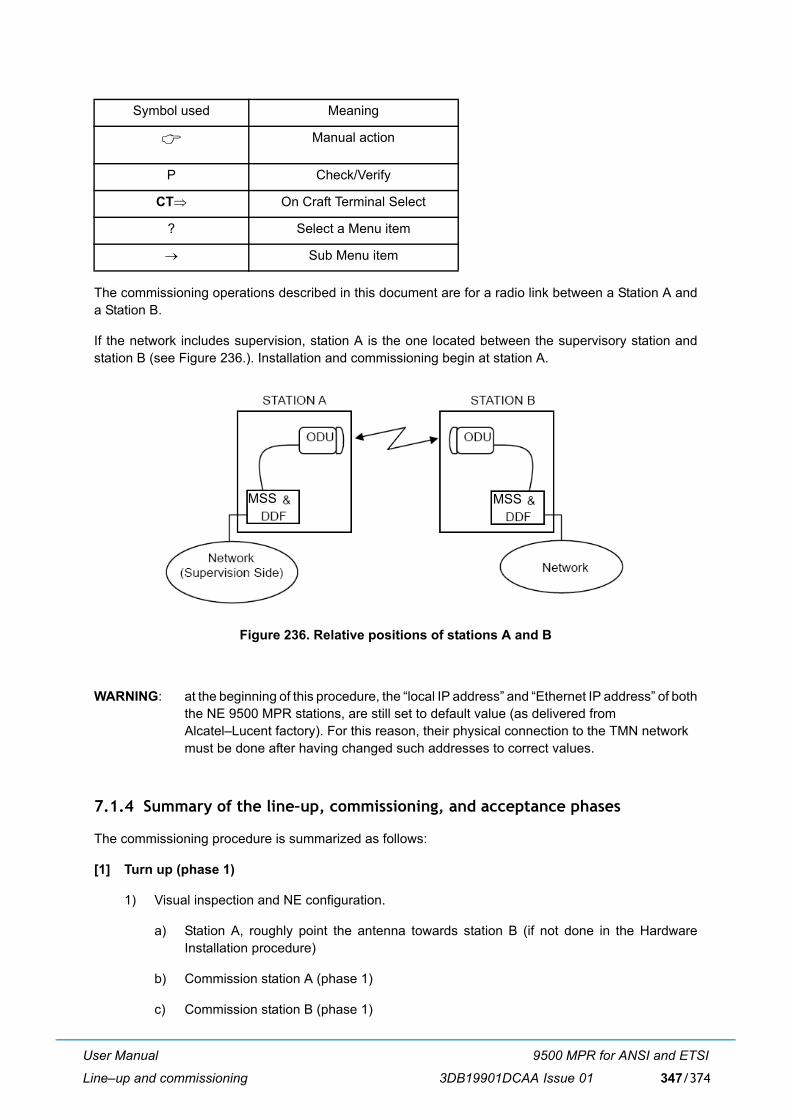
User Manual
Line�up and commissioning
9500 MPR for ANSI and ETSI
3DB19901DCAA Issue 01 347/374
The commissioning operations described in this document are for a radio link between a Station A anda Station B.
If the network includes supervision, station A is the one located between the supervisory station andstation B (see Figure 236.). Installation and commissioning begin at station A.
Figure 236. Relative positions of stations A and B
WARNING: at the beginning of this procedure, the �local IP address� and �Ethernet IP address� of boththe NE 9500 MPR stations, are still set to default value (as delivered from Alcatel�Lucent factory). For this reason, their physical connection to the TMN networkmust be done after having changed such addresses to correct values.
7.1.4 Summary of the line�up, commissioning, and acceptance phases
The commissioning procedure is summarized as follows:
[1] Turn up (phase 1)
1) Visual inspection and NE configuration.
a) Station A, roughly point the antenna towards station B (if not done in the HardwareInstallation procedure)
b) Commission station A (phase 1)
c) Commission station B (phase 1)
Symbol used Meaning
! Manual action
P Check/Verify
CT⇒ On Craft Terminal Select
? Select a Menu item
→ Sub Menu item
MSS MSS
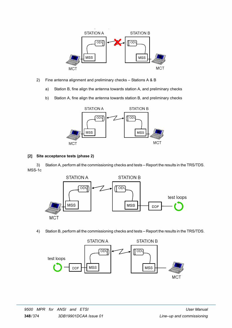
User Manual
Line�up and commissioning
9500 MPR for ANSI and ETSI
3DB19901DCAA Issue 01348/374
2) Fine antenna alignment and preliminary checks � Stations A & B
a) Station B, fine align the antenna towards station A, and preliminary checks
b) Station A, fine align the antenna towards station B, and preliminary checks
[2] Site acceptance tests (phase 2)
3) Station A, perform all the commissioning checks and tests � Report the results in the TRS/TDS.MSS-1c
4) Station B, perform all the commissioning checks and tests � Report the results in the TRS/TDS.
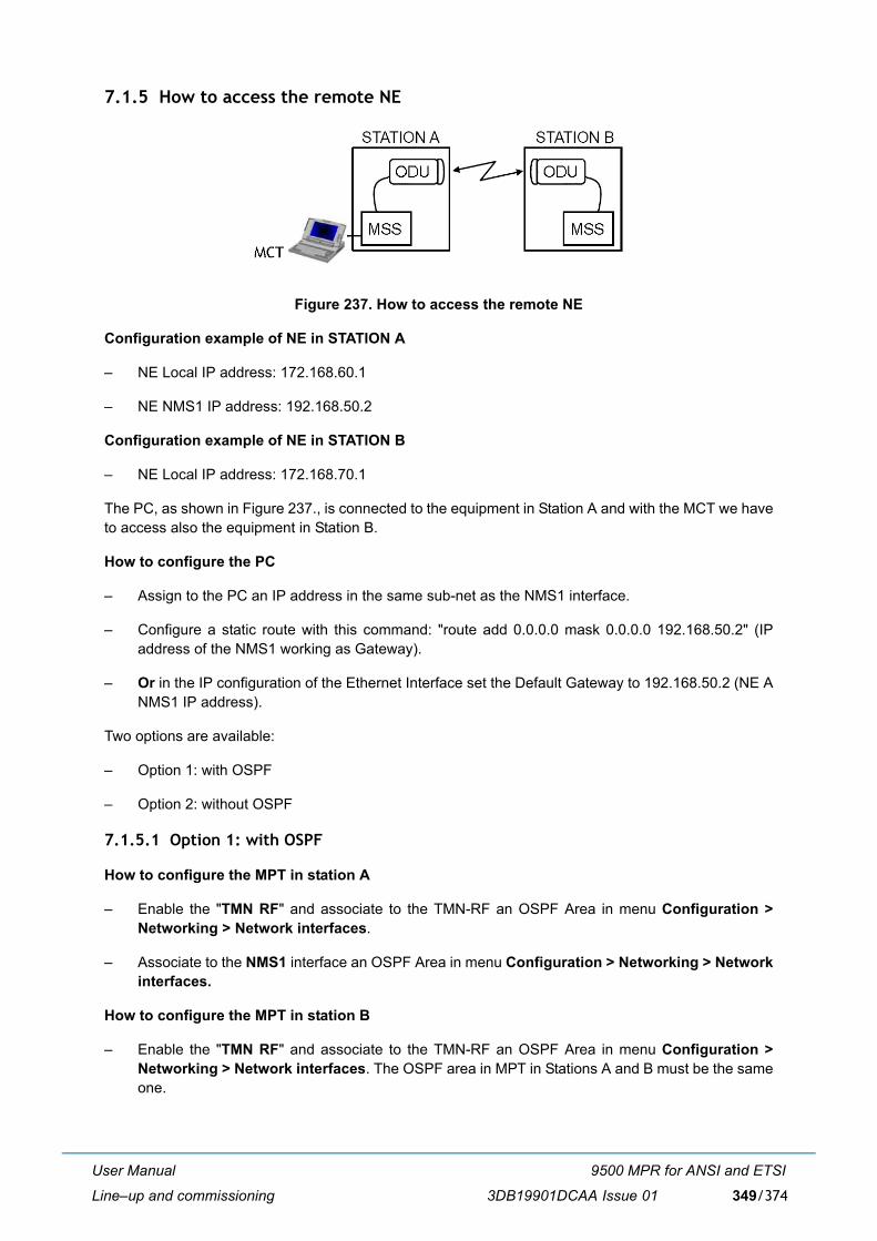
User Manual
Line�up and commissioning
9500 MPR for ANSI and ETSI
3DB19901DCAA Issue 01 349/374
7.1.5 How to access the remote NE
Figure 237. How to access the remote NE
Configuration example of NE in STATION A
� NE Local IP address: 172.168.60.1
� NE NMS1 IP address: 192.168.50.2
Configuration example of NE in STATION B
� NE Local IP address: 172.168.70.1
The PC, as shown in Figure 237., is connected to the equipment in Station A and with the MCT we haveto access also the equipment in Station B.
How to configure the PC
� Assign to the PC an IP address in the same sub-net as the NMS1 interface.
� Configure a static route with this command: "route add 0.0.0.0 mask 0.0.0.0 192.168.50.2" (IPaddress of the NMS1 working as Gateway).
� Or in the IP configuration of the Ethernet Interface set the Default Gateway to 192.168.50.2 (NE ANMS1 IP address).
Two options are available:
� Option 1: with OSPF
� Option 2: without OSPF
7.1.5.1 Option 1: with OSPF
How to configure the MPT in station A
� Enable the "TMN RF" and associate to the TMN-RF an OSPF Area in menu Configuration >Networking > Network interfaces.
� Associate to the NMS1 interface an OSPF Area in menu Configuration > Networking > Networkinterfaces.
How to configure the MPT in station B
� Enable the "TMN RF" and associate to the TMN-RF an OSPF Area in menu Configuration >Networking > Network interfaces. The OSPF area in MPT in Stations A and B must be the sameone.
User Manual
Line�up and commissioning
9500 MPR for ANSI and ETSI
3DB19901DCAA Issue 01350/374
7.1.5.2 Option 2: without OSPF
How to configure the MPT in station A
� Enable the "TMN RF Access" in menu Configuration > Networking > Network interfaces.
How to configure the MPT in station B
� Enable the "TMN RF Access" in menu Configuration > Networking > Network interfaces.
� Add the Static route "Default 0.0.0.0 0.0.0.0 Link on radio side" in menu Configuration >Networking > Static Routing.
� Or Add a static route to Network 192.168.50.0 255.255.255.0 Link on radio side.
� Or Add a static route to Host 192.168.50.x (PC IP address) 255.255.255.255 Link on radio side.
7.2 Commissioning of STATION A � phase 1 (turn up)
7.2.1 Turn�on preliminary operations
ALL THESE OPERATIONS ARE PERFORMED WITH THE POWER OFF
" The antenna of station A (or B) is pointed towards station B (or A) the best as possible (use compass if necessary).
" The hardware configuration of the equipment corresponds to the expected one.
" Make visual inspection for units� installation and cabling:
� The MSS-1c subrack allocation according to the station lay�out
� The MSS-1c subrack and units ground connections
� The power supply voltage is present with the correct polarity at the MSS-1c power supply input
� Tributaries are cabled on the station DDF
� The MSS-1c�ODU cables ground kit connections
� Where necessary, switch OFF the power supply before disconnecting the earth connection.
User Manual
Line�up and commissioning
9500 MPR for ANSI and ETSI
3DB19901DCAA Issue 01 351/374
� The ODU(s) ground connections (In the case of a non�integrated antenna, the antenna and theODU(s) must be ground connected)
� The MSS-1c(s) / ODU(s) cables are connected to MSS-1c(s) and ODU(s)
� The ODU(s) cables connectors waterproofing.
7.2.2 Powering up the MSS-1c(s) with ODU(s) connected
This operation has the following scopes:
� verify the SWP present both in MCT and NE
� make the Central Frequency and Shifter values of ODUs be acquired by MSS-1c (so that they areretained in the NE�s data base).
Proceed as follows:
a) Switch on the MSS-1c by using the circuit breakers
b) Connect locally the MCT to the MSS-1c of the local station and perform the NE login.
1) Make a local connection through the Ethernet cable, between the Ethernet port of the PC andthe NMS interface on the MSS-1c
2) Power on the PC and wait for its start�up
3) Start�up the MCT and wait for the welcome screen
4) Insert the �local IP address�
5) Start supervision on the local Network Element
c) Configure the NE as explained in the Provisioning chapter.
7.3 Commissioning of STATION B � phase 1 (turn up)
� To commission Station B, perform (at Station B premises) the same operations carried on at StationA�Phase 1.
! For near future tests, establish, on the DDF of Station B, hardware loops on every tributary.
7.4 Fine antenna alignment and preliminary checks � stations A & B
7.4.1 Fine antenna alignment
When Station A and Station B are fully configured and operational, and assuming that the antenna instation A (or B) has been previously correctly pointed toward the antenna in station B (or A), you shouldreceive some field from station B (or A).
Note 1: Verify that the ATPC is disabled.
User Manual
Line�up and commissioning
9500 MPR for ANSI and ETSI
3DB19901DCAA Issue 01352/374
Now, proceed to a fine tuning of the antenna to improve as much as possible the received level, in bothStation A (at Station A premises) and Station B (at Station B premises). To perform the fine antennaalignment refer to Annex A: fine antenna alignment on page 363.
7.4.2 Preliminary checks
At first on Station A (at Station A premises), then on Station B (at Station B premises), log in the NE andperform following checks by MCT:
7.4.2.1 Verify MPT alarm status
Purpose: Verify no abnormal communication alarm between MSS-1c and MPT
Required Instruments: PC with Craft Terminal software
Procedure: Connect MCT to MSS-1c.
! MCT ⇒ Alarms menu
" Verify in the alarms list for that there is no internal communication failure
" Verify in the alarms list that there is no TX failure
7.4.2.2 Transmitter power output check
Purpose: Verify via MCT the ODU(s) transmitted power output.
Required Instruments: PC with Craft Terminal software
Procedure: Connect MCT to MSS-1c.
! MCT ⇒ Monitoring → Power Measurement menu
" In Configuration → Radio menu, verify that ATPC is �Disabled� (If required, change the ATPC status to disable in the ATPC field)
" Verify that Tx Power value complies with the suitable value already set (If required, change the TxPower in the Configuration → Radio menu)
7.4.2.3 Received power measurement
Purpose: Verify via MCT the received power to detect any interference
Required Instruments: PC with Craft Terminal software
Procedure: Connect MCT to MSS-1c.
Subject On page
Verify ODU(s) alarm status 352
Transmitter power output check 352
Received power measurement 352

User Manual
Line�up and commissioning
9500 MPR for ANSI and ETSI
3DB19901DCAA Issue 01 353/374
! MCT ⇒ Monitoring → Power Measurement menu
→ In the Refresh period (sec), write the suitable measurement poling time (default = 5 sec)
Pressing �Start� will prompt a graphic monitoring view of the transmitted and received levels.
" Verify in the hop calculation (plant documentation) that the calculated received level has beenreached.
" Verify that there are no interferences.
7.5 End of commissioning phase 1 (Turn up) in STATION A
� In Station A, proceed to a final fine alignment of the antenna toward the antenna of Station B. Toperform the fine antenna alignment, refer to Annex A: fine antenna alignment on page 363.
� In Station A, proceed to the remote NE (station B) acquisition (by opening a second NETO session)in order to verify in both the stations:
" Received level complies with hop calculation
" No alarm showing (except unloaded tributaries)
7.6 Commissioning station A � phase 2 (acceptance test)
Commissioning phase 2 is a site acceptance test procedure made up of the required tests to ensure thatthe equipment is fully operational.
This phase describes first of all the way to check and to change (if necessary) via the Craft Terminal menuthe different configuration parameters already set, for most of them, during the Provisioning followed byvarious tests.
Most of the tests and checks results have to be recorded in the TRS (Test Results Sheet) (MPR-E)/TDS(Test Data Sheet) (MPR-A). Operator will be invited to do so each time it is required by the followingsentence: �Report� in the TRS/TDS.�
Note: The lettered titles in following tables [ a ) , b ) , etc.] correspond to the page�s heading titles ofthe TRS/TDS document.
Test On page Report in TRS/
TDS
a) Installation and cabling visual inspection 354
Indoor system installation and cabling visual inspection "
Outdoor system installation and cabling visual inspection "
b) System configuration 355
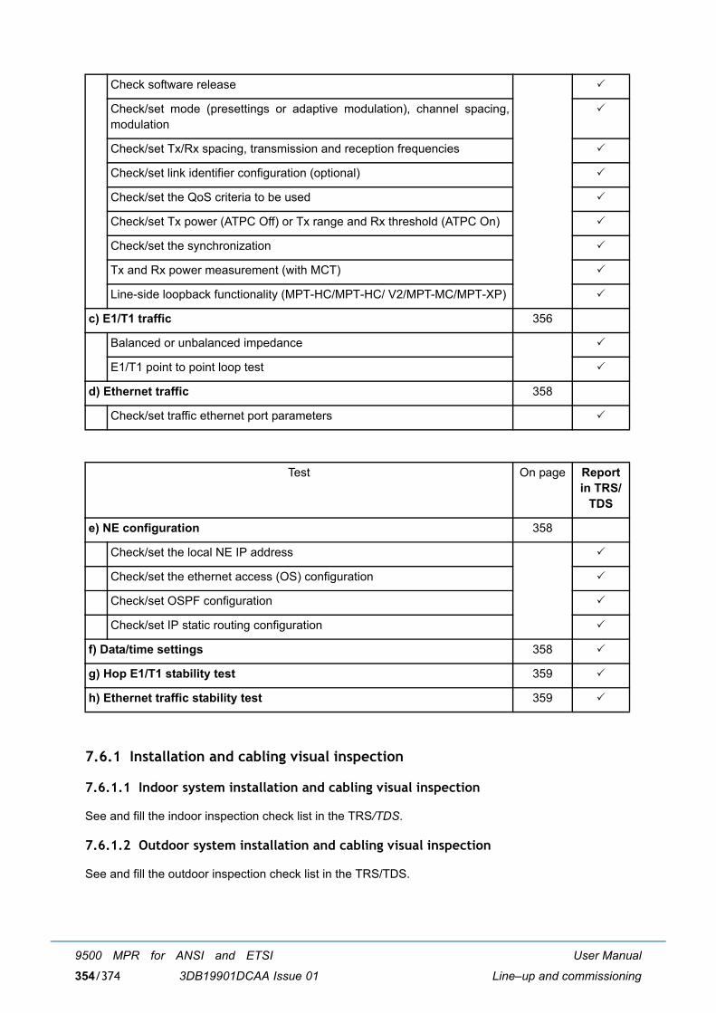
User Manual
Line�up and commissioning
9500 MPR for ANSI and ETSI
3DB19901DCAA Issue 01354/374
7.6.1 Installation and cabling visual inspection
7.6.1.1 Indoor system installation and cabling visual inspection
See and fill the indoor inspection check list in the TRS/TDS.
7.6.1.2 Outdoor system installation and cabling visual inspection
See and fill the outdoor inspection check list in the TRS/TDS.
Check software release "
Check/set mode (presettings or adaptive modulation), channel spacing,modulation
"
Check/set Tx/Rx spacing, transmission and reception frequencies "
Check/set link identifier configuration (optional) "
Check/set the QoS criteria to be used "
Check/set Tx power (ATPC Off) or Tx range and Rx threshold (ATPC On) "
Check/set the synchronization "
Tx and Rx power measurement (with MCT) "
Line-side loopback functionality (MPT-HC/MPT-HC/ V2/MPT-MC/MPT-XP) "
c) E1/T1 traffic 356
Balanced or unbalanced impedance "
E1/T1 point to point loop test "
d) Ethernet traffic 358
Check/set traffic ethernet port parameters "
Test On page Report in TRS/
TDS
e) NE configuration 358
Check/set the local NE IP address "
Check/set the ethernet access (OS) configuration "
Check/set OSPF configuration "
Check/set IP static routing configuration "
f) Data/time settings 358 "
g) Hop E1/T1 stability test 359 "
h) Ethernet traffic stability test 359 "

User Manual
Line�up and commissioning
9500 MPR for ANSI and ETSI
3DB19901DCAA Issue 01 355/374
7.6.2 System configuration
Purpose: Verify via MCT the configuration of the Local Station.Required Instruments: PC with Craft Terminal softwareProcedure: Connect MCT to MSS-1c
7.6.2.1 Check software release
! MCT ⇒ Menu Commissioning → Software Download → Tab-panel Software Package Versions
Check the Software release.
Report in the TRS/TDS.
7.6.2.2 Check/set mode (presettings or adaptive modulation), channel spacing, modulation
! MCT ⇒ Menu Configuration → Radio
If required, change any parameter.
Report the parameters in the TRS/TDS.
7.6.2.3 Check/set Tx/Rx spacing, transmission and reception frequencies
! MCT ⇒ Menu Configuration → Radio
Report the Shifter, Tx and the Rx frequencies in the TRS/TDS.
If required, change the Tx frequency. Rx Freq. will be automatically adjusted.
7.6.2.4 Check/set link identifier configuration (optional)
! MCT ⇒ Menu Configuration → Advanced Radio
If it is necessary, change any parameter.
Report the Link Identifier status (Enabled or Disabled), and, if Enabled, the �Expected� and �Sent� values.
7.6.2.5 Check/set the QoS criteria to be used
! MCT ⇒ Menu Configuration → MSS-1c Provisioning → Bridge Provisioning
Select the suitable QoS criteria to be used: Disabled/802.1p/DiffServ.
Report in the TRS/TDS.
7.6.2.6 Check/set Tx power (ATPC Off) or Tx range and Rx threshold (ATPC On)
! MCT ⇒ Menu Configuration → Radio
" ATPC �Disabled�Report the ATPC �Disabled� status, Tx nominal Power and Tx Power setting into the TRS/TDS.
" ATPC �Enabled�Report the ATPC �Enabled� status, ATPC Range and ATPC RX Threshold setting in the TRS/TDS.
If required, change ATPC Mode or ATPC Range or ATPC Rx Threshold then → Apply

User Manual
Line�up and commissioning
9500 MPR for ANSI and ETSI
3DB19901DCAA Issue 01356/374
7.6.2.7 Check/set the synchronization
! MCT ⇒ Menu Configuration → MSS-1c Provisioning → Synchronization Provisioning
Check/set all the parameters regarding the synchronization.
Report in the TRS/TDS.
7.6.2.8 Tx and Rx power measurement (with MCT)
Purpose: Verify via MCT the Transmitted (PTx) and Received (PRx) power.
Required Instruments: PC with Craft Terminal software
Procedure: Connect MCT to MSS-1c
! MCT ⇒ Menu Monitoring → Power Measurements
→ In the Refresh Period (sec) write the suitable measurement polling time then press → Start
Pressing �Start� will prompt a graphic monitoring view of the transmitted and received levels.
Report the Current Tx Local End (PTx) and the current Rx Local End (PRx) in the TRS/TDS.
7.6.2.9 Line-side loopback functionality (MPT-HC/MPT-HC/ V2/MPT-MC/MPT-XP)
Purpose: Verify via MCT the Line-side loopback functionality (only in the local NE)
Required Instruments: PC with Craft Terminal software and E1/T1 Data Analyzer
Procedure: Connect MCT to MSS-1cConnect Pattern Generator/Error Detector analyzer on one Tributary Access(At the Station DDF)
� A delay up to 10 seconds may be observed for each activation/deactivation.� Ensure that the local tributary access is active (unframed and configured).
! MCT ⇒ Menu Troubleshooting → Select Line Side → Press Activate
" Error Detector showing no errors." Loopback showing in the Troubleshooting view.
To remove the loopback press Deactivate.
Report about the Loopback functionality in the TRS/TDS.
7.6.3 E1/T1 traffic
7.6.3.1 Balanced or unbalanced impedance
! MCT ⇒ Menu Configuration → MSS-1c Provisioning → PDH port Provisioning
Set the impedance for the E1/T1 streams.
Report the Impedance in the TRS/TDS.
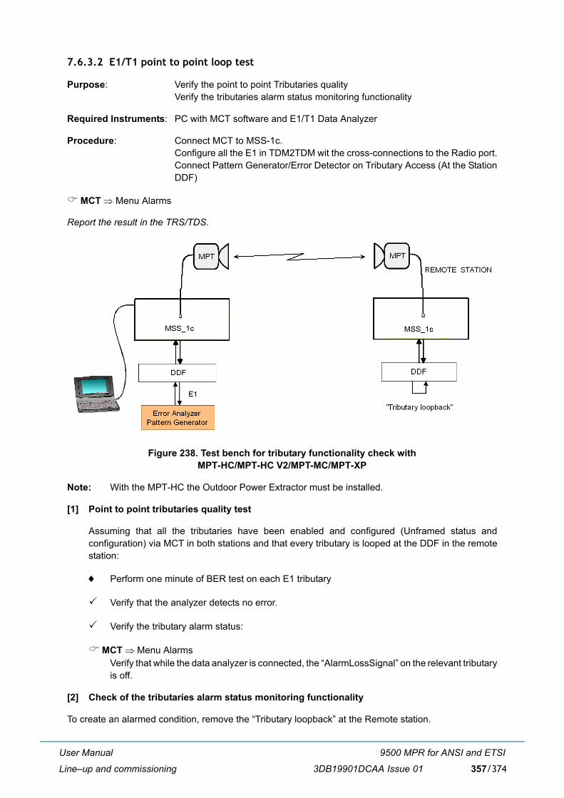
User Manual
Line�up and commissioning
9500 MPR for ANSI and ETSI
3DB19901DCAA Issue 01 357/374
7.6.3.2 E1/T1 point to point loop test
Purpose: Verify the point to point Tributaries qualityVerify the tributaries alarm status monitoring functionality
Required Instruments: PC with MCT software and E1/T1 Data Analyzer
Procedure: Connect MCT to MSS-1c.Configure all the E1 in TDM2TDM wit the cross-connections to the Radio port.Connect Pattern Generator/Error Detector on Tributary Access (At the StationDDF)
! MCT ⇒ Menu Alarms
Report the result in the TRS/TDS.
Figure 238. Test bench for tributary functionality check withMPT-HC/MPT-HC V2/MPT-MC/MPT-XP
Note: With the MPT-HC the Outdoor Power Extractor must be installed.
[1] Point to point tributaries quality test
Assuming that all the tributaries have been enabled and configured (Unframed status andconfiguration) via MCT in both stations and that every tributary is looped at the DDF in the remotestation:
♦ Perform one minute of BER test on each E1 tributary
" Verify that the analyzer detects no error.
" Verify the tributary alarm status:
! MCT ⇒ Menu AlarmsVerify that while the data analyzer is connected, the �AlarmLossSignal� on the relevant tributaryis off.
[2] Check of the tributaries alarm status monitoring functionality
To create an alarmed condition, remove the �Tributary loopback� at the Remote station.
User Manual
Line�up and commissioning
9500 MPR for ANSI and ETSI
3DB19901DCAA Issue 01358/374
In Menu Alarms, verify that while the data analyzer is connected, the �AlarmLossSignal� on the relevanttributary goes on.
Restore the �Tributary loopback� at the Remote station, and verify that the �AlarmLossSignal� on therelevant tributary goes off.
7.6.4 Ethernet traffic
7.6.4.1 Check/set traffic ethernet port parameters
! MCT ⇒ Menu Configuration → MSS-1c Provisioning → Ethernet port Provisioning
Check and, if it is necessary, change the parameters.
Report in the TRS/TDS.
7.6.5 NE configuration
7.6.5.1 Check/set the local NE IP address
! MCT ⇒ Menu Configuration → Networking → Network Interfaces
Report the local IP Address in the TRS/TDS.
7.6.5.2 Check/set the ethernet access (OS) configuration
! MCT ⇒ Menu Configuration → Networking → Network Interfaces → NMS IP parameters
Report the IP Address and IP Mask in the TRS/TDS.
7.6.5.3 Check/set OSPF configuration
! MCT ⇒ Menu Configuration → Networking → Network Interfaces → OSPF Management
Report the OSPF management in the TRS/TDS.
7.6.5.4 Check/set IP static routing configuration
! MCT ⇒ Menu Configuration → Networking → Static Routing
Report the IP Address, IP Mask and Default gateway IP Address or interface type into the TRS/TDS.
7.6.6 Data/time settings
! MCT ⇒ Menu bar ⇒ Configuration ⇒ NE Time
Enter the time settings.
Report in the TRS/TDS.
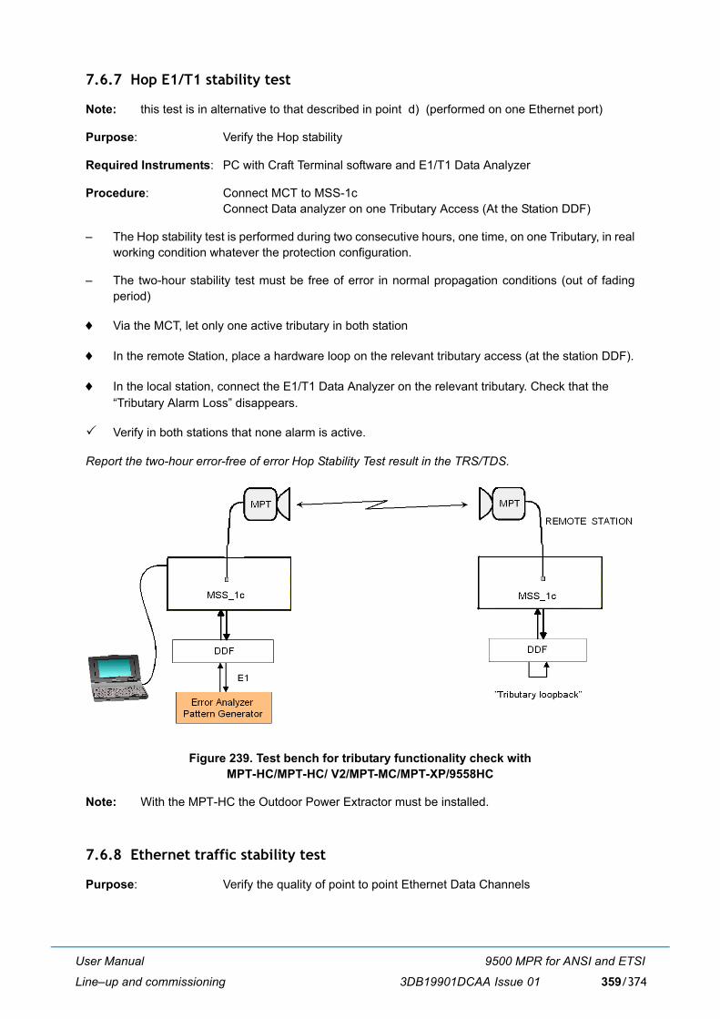
User Manual
Line�up and commissioning
9500 MPR for ANSI and ETSI
3DB19901DCAA Issue 01 359/374
7.6.7 Hop E1/T1 stability test
Note: this test is in alternative to that described in point d) (performed on one Ethernet port)
Purpose: Verify the Hop stability
Required Instruments: PC with Craft Terminal software and E1/T1 Data Analyzer
Procedure: Connect MCT to MSS-1cConnect Data analyzer on one Tributary Access (At the Station DDF)
� The Hop stability test is performed during two consecutive hours, one time, on one Tributary, in realworking condition whatever the protection configuration.
� The two-hour stability test must be free of error in normal propagation conditions (out of fadingperiod)
♦ Via the MCT, let only one active tributary in both station
♦ In the remote Station, place a hardware loop on the relevant tributary access (at the station DDF).
♦ In the local station, connect the E1/T1 Data Analyzer on the relevant tributary. Check that the �Tributary Alarm Loss� disappears.
" Verify in both stations that none alarm is active.
Report the two-hour error-free of error Hop Stability Test result in the TRS/TDS.
Figure 239. Test bench for tributary functionality check withMPT-HC/MPT-HC/ V2/MPT-MC/MPT-XP/9558HC
Note: With the MPT-HC the Outdoor Power Extractor must be installed.
7.6.8 Ethernet traffic stability test
Purpose: Verify the quality of point to point Ethernet Data Channels

User Manual
Line�up and commissioning
9500 MPR for ANSI and ETSI
3DB19901DCAA Issue 01360/374
Required instruments: PC with Craft Terminal software and, in alternative:� 1 additional PC and 1 Ethernet cable� 2 additional PCs� 2 Ethernet Data Analyzers
Procedure:
a) Connect MCT to MSS-1c of local station.
b) Perform the connectivity test on user port #1, according to the chosen test bench:
� Test bench with 1 additional PC and 1 Ethernet cable: see point [1]
� Test bench with 2 additional PCs: see point [2]
� Test bench with 2 Ethernet Data Analyzers: see point [3]
c) Set with the MCT the bridge configuration to 802.1D.
d) Perform the connectivity test on user ports #2, #3 and #4 (if required)If required in plant documentation, repeat the connectivity test [step b) above] for the other threeports, with obvious test bench changes on remote station.
Report about the connectivity test of Ethernet Data Channels in the TRS/TDS.
e) Perform the hop stability test
1) Set up the test bench with 2 Ethernet Data Analyzers (point [3]). On both stations, connect theData analyzer on Ethernet port #1.
2) Start this test after the �learning� of the MAC address.
3) Configure the Pattern generator in order to generate continuos traffic and set the data rate halfto the radio capacity and with packet size of 1518 bytes.
4) Perform the stability test for 2 hours.
5) Compare the number of Tx and Rx Frames on the Pattern A: the number of frames must beequal in normal propagation conditions (out of fading period).
Report the two-hour error-free Ethernet Stability Test result in the TRS/TDS.
[1] Test bench with 1 additional PC and 1 ethernet cable
a) ConnectionsOn local station, connect the additional PC on Ethernet port #1 (testing port).On remote station, through the Ethernet cable, connect the NMS Ethernet port to theEthernet port #1 (port to be tested)
b) Set �Enable�, �Flow Control disable�, and �Capability Advertised� for ports to testPerform the following operations on each data port (Ethernet ports #1 to #4) of bothstations:� State ⇒ Enabled� Auto Negotiation Status ⇒ Forced� Flow Control ⇒ Disabled � Speed ⇒ �1000 Mb/s�� Duplex mode ⇒ Full
c) Perform the connectivity test on port #1
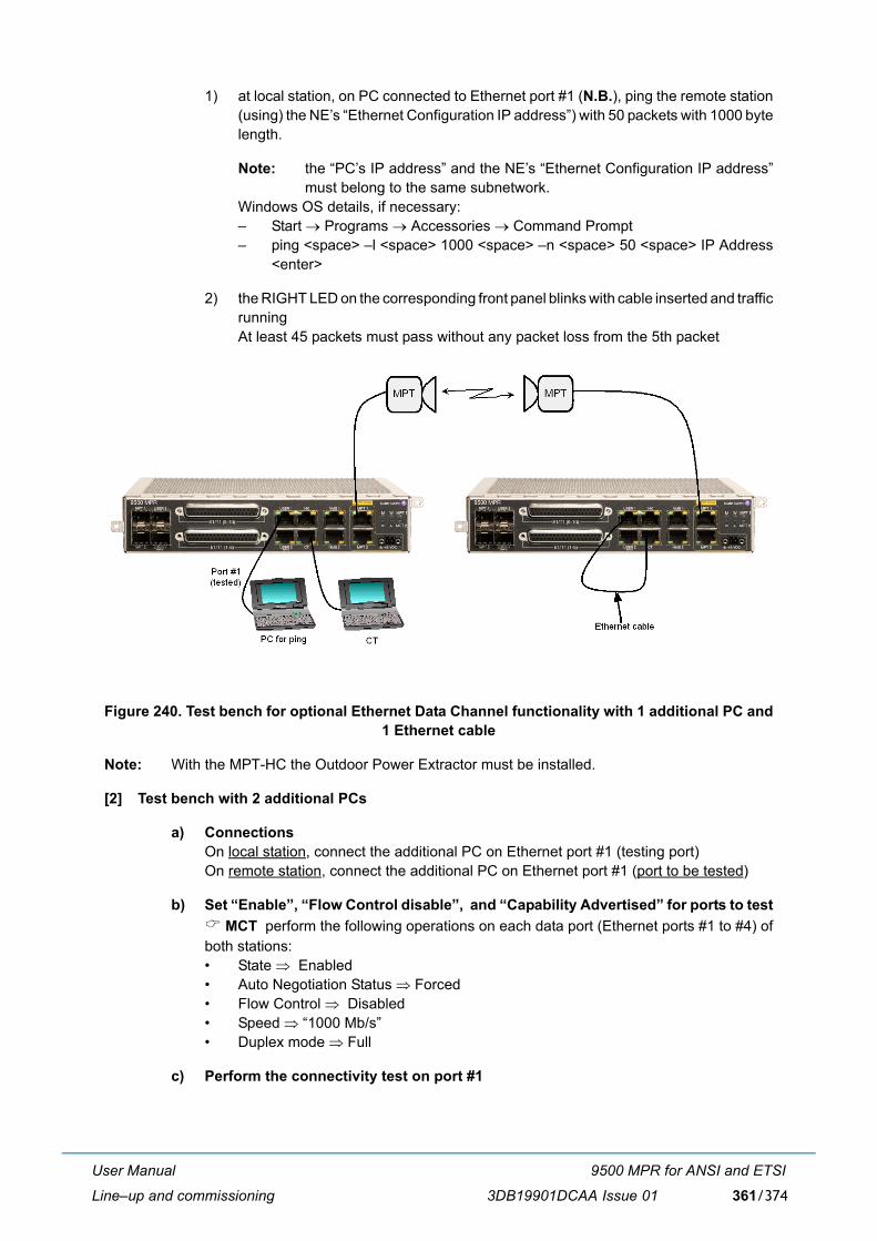
User Manual
Line�up and commissioning
9500 MPR for ANSI and ETSI
3DB19901DCAA Issue 01 361/374
1) at local station, on PC connected to Ethernet port #1 (N.B.), ping the remote station(using) the NE�s �Ethernet Configuration IP address�) with 50 packets with 1000 bytelength.
Note: the �PC�s IP address� and the NE�s �Ethernet Configuration IP address�must belong to the same subnetwork.
Windows OS details, if necessary:� Start → Programs → Accessories → Command Prompt� ping <space> �l <space> 1000 <space> �n <space> 50 <space> IP Address
<enter>
2) the RIGHT LED on the corresponding front panel blinks with cable inserted and trafficrunningAt least 45 packets must pass without any packet loss from the 5th packet
Figure 240. Test bench for optional Ethernet Data Channel functionality with 1 additional PC and1 Ethernet cable
Note: With the MPT-HC the Outdoor Power Extractor must be installed.
[2] Test bench with 2 additional PCs
a) ConnectionsOn local station, connect the additional PC on Ethernet port #1 (testing port)On remote station, connect the additional PC on Ethernet port #1 (port to be tested)
b) Set �Enable�, �Flow Control disable�, and �Capability Advertised� for ports to test! MCT perform the following operations on each data port (Ethernet ports #1 to #4) ofboth stations:� State ⇒ Enabled� Auto Negotiation Status ⇒ Forced� Flow Control ⇒ Disabled � Speed ⇒ �1000 Mb/s�� Duplex mode ⇒ Full
c) Perform the connectivity test on port #1
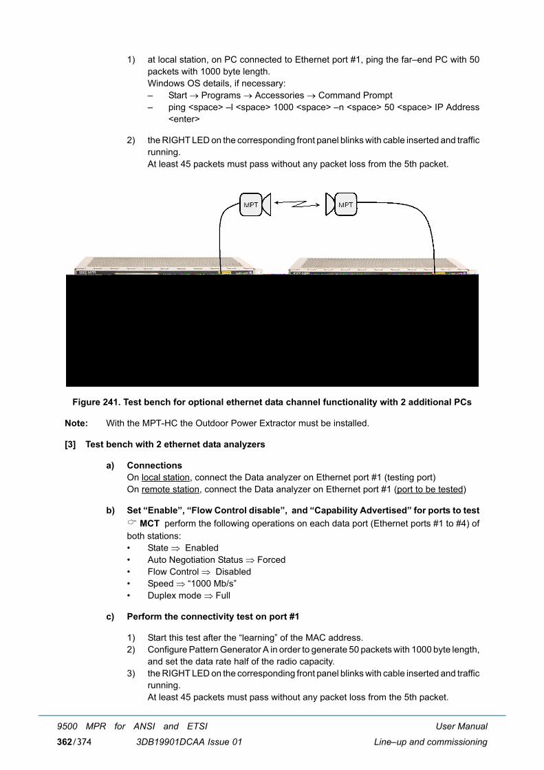
User Manual
Line�up and commissioning
9500 MPR for ANSI and ETSI
3DB19901DCAA Issue 01362/374
1) at local station, on PC connected to Ethernet port #1, ping the far�end PC with 50packets with 1000 byte length.Windows OS details, if necessary:� Start → Programs → Accessories → Command Prompt� ping <space> �l <space> 1000 <space> �n <space> 50 <space> IP Address
<enter>
2) the RIGHT LED on the corresponding front panel blinks with cable inserted and trafficrunning.At least 45 packets must pass without any packet loss from the 5th packet.
Figure 241. Test bench for optional ethernet data channel functionality with 2 additional PCs
Note: With the MPT-HC the Outdoor Power Extractor must be installed.
[3] Test bench with 2 ethernet data analyzers
a) ConnectionsOn local station, connect the Data analyzer on Ethernet port #1 (testing port)On remote station, connect the Data analyzer on Ethernet port #1 (port to be tested)
b) Set �Enable�, �Flow Control disable�, and �Capability Advertised� for ports to test! MCT perform the following operations on each data port (Ethernet ports #1 to #4) ofboth stations:� State ⇒ Enabled� Auto Negotiation Status ⇒ Forced� Flow Control ⇒ Disabled � Speed ⇒ �1000 Mb/s�� Duplex mode ⇒ Full
c) Perform the connectivity test on port #1
1) Start this test after the �learning� of the MAC address.2) Configure Pattern Generator A in order to generate 50 packets with 1000 byte length,
and set the data rate half of the radio capacity.3) the RIGHT LED on the corresponding front panel blinks with cable inserted and traffic
running.At least 45 packets must pass without any packet loss from the 5th packet.
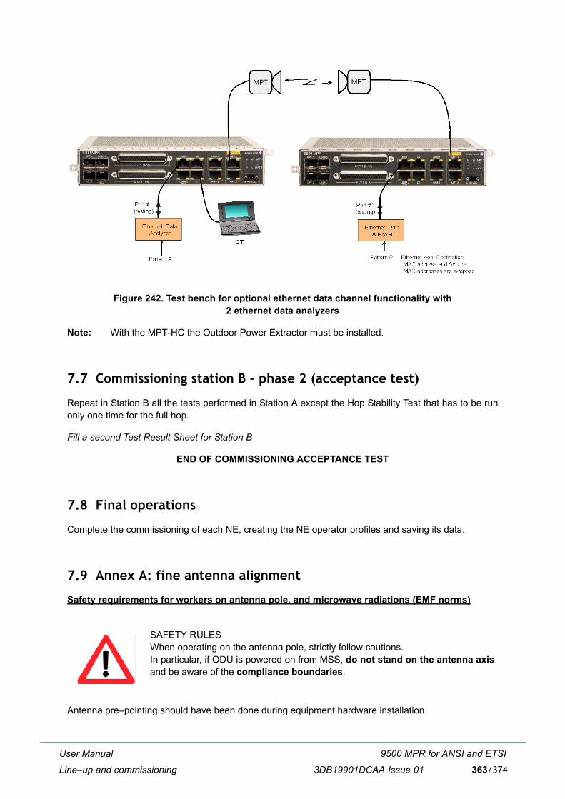
User Manual
Line�up and commissioning
9500 MPR for ANSI and ETSI
3DB19901DCAA Issue 01 363/374
Figure 242. Test bench for optional ethernet data channel functionality with 2 ethernet data analyzers
Note: With the MPT-HC the Outdoor Power Extractor must be installed.
7.7 Commissioning station B � phase 2 (acceptance test)
Repeat in Station B all the tests performed in Station A except the Hop Stability Test that has to be runonly one time for the full hop.
Fill a second Test Result Sheet for Station B
END OF COMMISSIONING ACCEPTANCE TEST
7.8 Final operations
Complete the commissioning of each NE, creating the NE operator profiles and saving its data.
7.9 Annex A: fine antenna alignment
Safety requirements for workers on antenna pole, and microwave radiations (EMF norms)
Antenna pre�pointing should have been done during equipment hardware installation.
SAFETY RULESWhen operating on the antenna pole, strictly follow cautions. In particular, if ODU is powered on from MSS, do not stand on the antenna axisand be aware of the compliance boundaries.

User Manual
Line�up and commissioning
9500 MPR for ANSI and ETSI
3DB19901DCAA Issue 01364/374
This annex explains how to carry out the antenna fine alignment.
To monitor the received level during alignment in the local station:
� use the ODU Rx power monitoring in addition to a voltmeter,
� or, after having logged in the NE, use the Craft Terminal received power measurement facility
Alignment procedure using the ODU Rx power monitoring
a) the radio link must be up and the ATPC disabled
b) in general, fine alignment should be done only on one station of the radio link
c) connect a voltmeter to the ODU (by using the Light Service kit cable for the MPT)
d) proceed with Vertical alignment, then with Horizontal alignment
e) in configurations with two antennas, repeat the procedure for the second antenna.
Note: Procedures for Vertical and Horizontal alignment depend on the type of integrated polemounting employed.

User Manual
Abbreviations
9500 MPR for ANSI and ETSI
3DB19901DCAA Issue 01 365/374
ABBREVIATIONS
ABBREVIATION MEANING
ACM Adaptive Coding Modulation
ADM Add Drop Multiplexer
AIS Alarm Indication Signal
ALS Automatic Laser Shutdown
ANSI American National Standards Association, for the North American market
AP Access Point
APS Automatic Protection Switching
APT Active Problem Table
AS Alarm Surveillance
ASAP Alarm Severity Assignment Profile
ATPC Automatic Transmit Power Control
AVC Attribute Value Change
BBE Background Block Error
BER Bit Error Rate
BR & SW Bridge & Switch
Browser Application which allows to browse all RM-MIB objects
CLNP Connection Less Network Protocol
CD Current Data
CDCC Data Communication Channel
CD-ROM Compact Disc Read Only Memory
CES Circuit Emulation Service
CI Communication Infrastructure
CLA Common Loss Alarm
CRU Clock Reference Unit
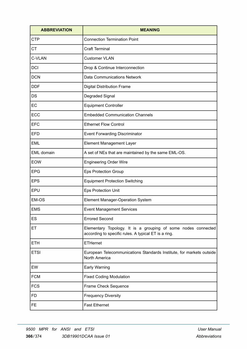
User Manual
Abbreviations
9500 MPR for ANSI and ETSI
3DB19901DCAA Issue 01366/374
CTP Connection Termination Point
CT Craft Terminal
C-VLAN Customer VLAN
DCI Drop & Continue Interconnection
DCN Data Communications Network
DDF Digital Distribution Frame
DS Degraded Signal
EC Equipment Controller
ECC Embedded Communication Channels
EFC Ethernet Flow Control
EFD Event Forwarding Discriminator
EML Element Management Layer
EML domain A set of NEs that are maintained by the same EML-OS.
EOW Engineering Order Wire
EPG Eps Protection Group
EPS Equipment Protection Switching
EPU Eps Protection Unit
EM-OS Element Manager-Operation System
EMS Event Management Services
ES Errored Second
ET Elementary Topology. It is a grouping of some nodes connectedaccording to specific rules. A typical ET is a ring.
ETH ETHernet
ETSI European Telecommunications Standards Institute, for markets outsideNorth America
EW Early Warning
FCM Fixed Coding Modulation
FCS Frame Check Sequence
FD Frequency Diversity
FE Fast Ethernet
ABBREVIATION MEANING

User Manual
Abbreviations
9500 MPR for ANSI and ETSI
3DB19901DCAA Issue 01 367/374
FLS Frame Loss Second
FM FM Fault Management
Gbit/s Gigabits per second
GFP Generic Frame Protocol
GNE Gateway Network Element
HBER High Bit Error Ratio
HD History Data
HET Hetero frequency
HS Hitless Switch
HSB Hot Stand-By
HTML Hyper Text Markup Language
ICP Internal Communication Problem
IDU InDoor Unit
IM Information Model
IP Internet Protocol
IWF Inter-Working Function
IEEE Institute of Electrical and Electronics Engineers
IM Information Manager
JUSM Java User Service Manager
Kbit/s Kilobits per second
LAG Link Aggregation Group
LAN Local Area Network
LAPD Link Access Procedure on D-channel
LBER Low Bit Error Ratio
LCT Local Craft Terminal
LDPC Low Density Parity Check
LOF Loss Of Frame
LOS Loss Of Signal
MAC Medium Access Control
MAU Medium Attachment Unit
ABBREVIATION MEANING
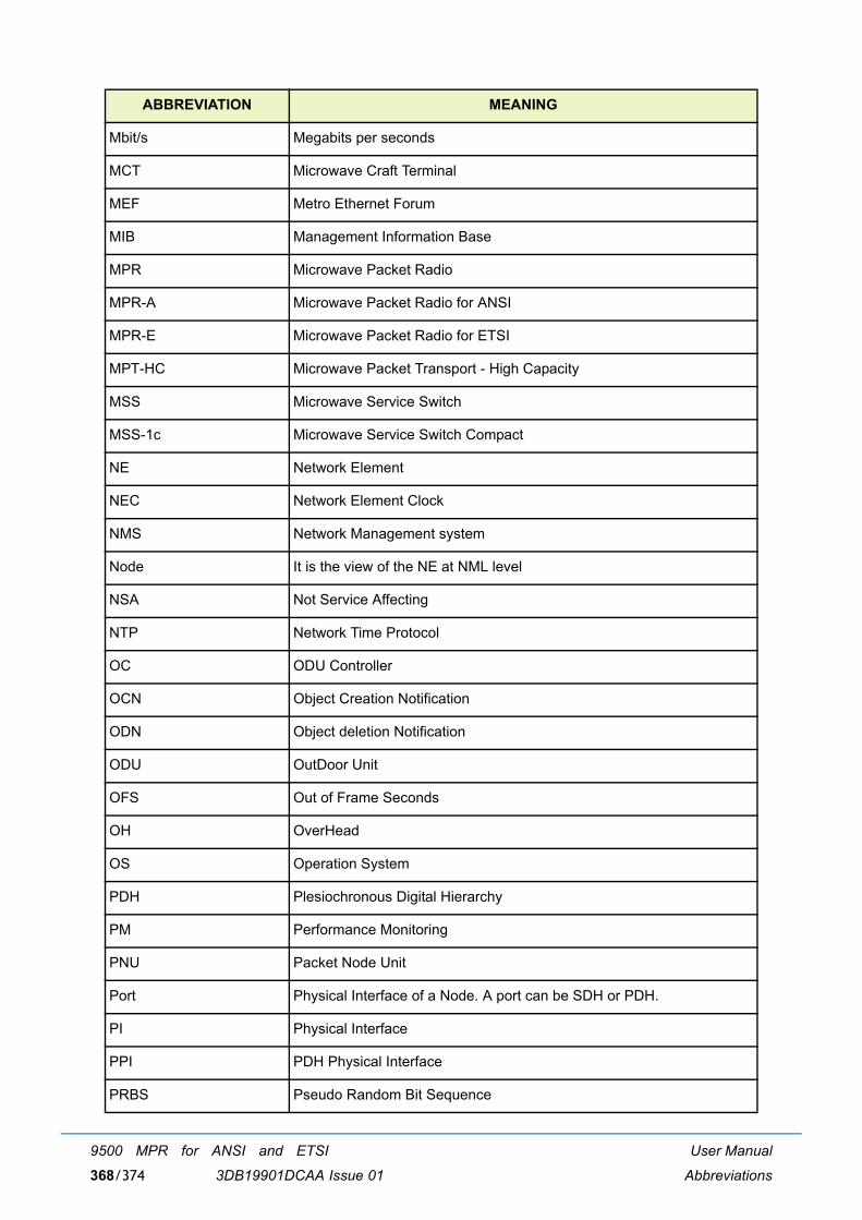
User Manual
Abbreviations
9500 MPR for ANSI and ETSI
3DB19901DCAA Issue 01368/374
Mbit/s Megabits per seconds
MCT Microwave Craft Terminal
MEF Metro Ethernet Forum
MIB Management Information Base
MPR Microwave Packet Radio
MPR-A Microwave Packet Radio for ANSI
MPR-E Microwave Packet Radio for ETSI
MPT-HC Microwave Packet Transport - High Capacity
MSS Microwave Service Switch
MSS-1c Microwave Service Switch Compact
NE Network Element
NEC Network Element Clock
NMS Network Management system
Node It is the view of the NE at NML level
NSA Not Service Affecting
NTP Network Time Protocol
OC ODU Controller
OCN Object Creation Notification
ODN Object deletion Notification
ODU OutDoor Unit
OFS Out of Frame Seconds
OH OverHead
OS Operation System
PDH Plesiochronous Digital Hierarchy
PM Performance Monitoring
PNU Packet Node Unit
Port Physical Interface of a Node. A port can be SDH or PDH.
PI Physical Interface
PPI PDH Physical Interface
PRBS Pseudo Random Bit Sequence
ABBREVIATION MEANING
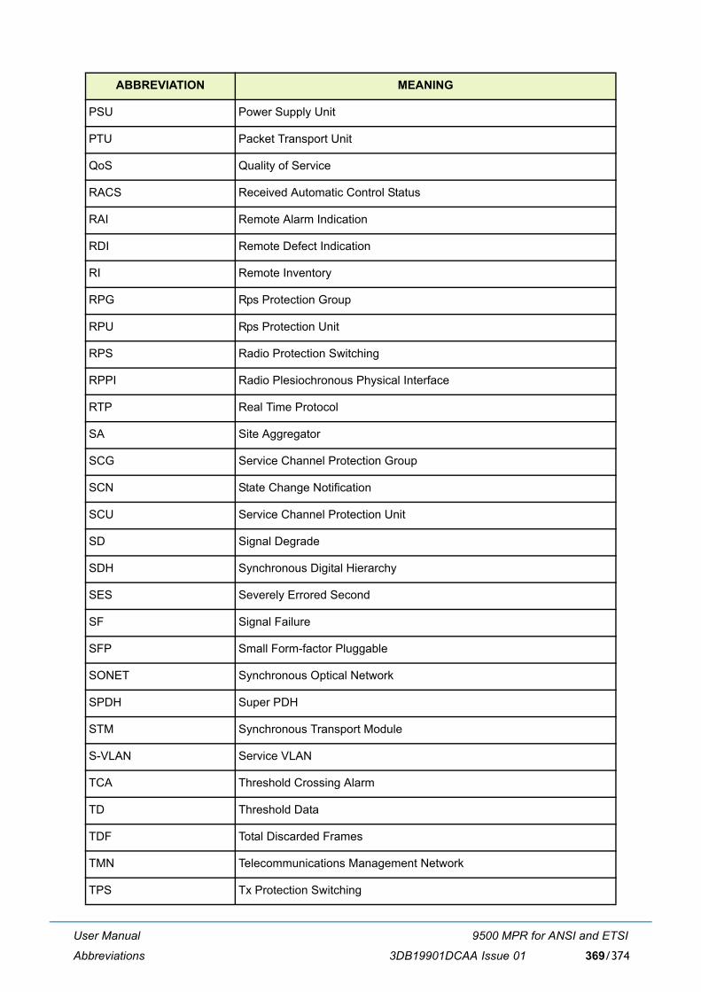
User Manual
Abbreviations
9500 MPR for ANSI and ETSI
3DB19901DCAA Issue 01 369/374
PSU Power Supply Unit
PTU Packet Transport Unit
QoS Quality of Service
RACS Received Automatic Control Status
RAI Remote Alarm Indication
RDI Remote Defect Indication
RI Remote Inventory
RPG Rps Protection Group
RPU Rps Protection Unit
RPS Radio Protection Switching
RPPI Radio Plesiochronous Physical Interface
RTP Real Time Protocol
SA Site Aggregator
SCG Service Channel Protection Group
SCN State Change Notification
SCU Service Channel Protection Unit
SD Signal Degrade
SDH Synchronous Digital Hierarchy
SES Severely Errored Second
SF Signal Failure
SFP Small Form-factor Pluggable
SONET Synchronous Optical Network
SPDH Super PDH
STM Synchronous Transport Module
S-VLAN Service VLAN
TCA Threshold Crossing Alarm
TD Threshold Data
TDF Total Discarded Frames
TMN Telecommunications Management Network
TPS Tx Protection Switching
ABBREVIATION MEANING

User Manual
Abbreviations
9500 MPR for ANSI and ETSI
3DB19901DCAA Issue 01370/374
TPG Tps Protection Group
TPU Tps Protection Unit
TRCF Total Received Correct Frames
TRCO Total Received Correct Octets
TRSEF Total Received Service Errored Frames
TRsp Tx Rx spacing
TRU Top Rack Unit
TS Time Slot
TTF Total Transmitted Frames
TTO Total Transmitted Octets
TTP Trail Termination Point
UAS UnAvailable Second
UAT UnAvailable Time
USM User Service Manager
UPA Unavailable path alarm
URU Underlying Resource Unavailable
VLAN Virtual Local Area Network
WTR Wait Time to Restore
XCO Cross-connection
ABBREVIATION MEANING

Customer documentation and productsupport
Customer documentationhttp://www.alcatel-lucent.com/myaccess
Product manuals and documentation updates are available at alcatel-lucent.com. If you are a new user and require access to this service, please contact your Alcatel-Lucent sales representative.
Technical supporthttp://support.alcatel-lucent.com
Documentation [email protected]

© 2013 Alcatel-Lucent. All rights reserved.3DB 19901 DCAA Edition 01