9500 mpr rel.4.2.0 mpr-e mpt-hc v2 mpt-mc mpt-xp usermanual.3db19901ecaa 01
DESCRIPTION
Mpt user manualTRANSCRIPT

Alcatel-Lucent 9500MICROWAVE PACKET RADIO for ANSI | RELEASE 4.2.0MPR-e (Outdoor units: MPT-HC V2/MPT-XP/9558HC)
Alcatel-Lucent 9500MICROWAVE PACKET RADIO for ETSI | RELEASE 4.2.0MPR-e (Outdoor units: MPT-HC V2/MPT-MC/MPT-XP)
Alcatel-Lucent ProprietaryThis document contains proprietary information of Alcatel-Lucent and is not to be disclosedor used except in accordance with applicable agreements.Copyright 2013 © Alcatel-Lucent. All rights reserved.
Main Documentation
MPR-e User Manual
User Manual3DB 19901 ECAA Edition 01

Alcatel-Lucent assumes no responsibility for the accuracy of the information presented, which is subject to change without notice.
Alcatel, Lucent, Alcatel-Lucent and the Alcatel-Lucent logo are trademarks of Alcatel-Lucent. All other trademarks are the property of their respective owners.
Copyright 2013 Alcatel-Lucent.
All rights reserved.
Disclaimers
Alcatel-Lucent products are intended for commercial uses. Without the appropriate network design engineering, they must not be sold, licensed or otherwise distributed for use in any hazardous environments requiring fail-safe performance, such as in the operation of nuclear facilities, aircraft navigation or communication systems, air traffic control, direct life-support machines, or weapons systems, in which the failure of products could lead directly to death, personal injury, or severe physical or environmental damage. The customer hereby agrees that the use, sale, license or other distribution of the products for any such application without the prior written consent of Alcatel-Lucent, shall be at the customer's sole risk. The customer hereby agrees to defend and hold Alcatel-Lucent harmless from any claims for loss, cost, damage, expense or liability that may arise out of or in connection with the use, sale, license or other distribution of the products in such applications.
This document may contain information regarding the use and installation of non-Alcatel-Lucent products. Please note that this information is provided as a courtesy to assist you. While Alcatel-Lucent tries to ensure that this information accurately reflects information provided by the supplier, please refer to the materials provided with any non-Alcatel-Lucent product and contact the supplier for confirmation. Alcatel-Lucent assumes no responsibility or liability for incorrect or incomplete information provided about non-Alcatel-Lucent products.
However, this does not constitute a representation or warranty. The warranties provided for Alcatel-Lucent products, if any, are set forth in contractual documentation entered into by Alcatel-Lucent and its customers.
This document was originally written in English. If there is any conflict or inconsistency between the English version and any other version of a document, the English version shall prevail.

User Manual
Table of Contents
9500 MPR for ANSI and ETSI
3DB19901ECAA Issue 01 1/374
TABLE OF CONTENTS
LIST OF FIGURES ......................................................................................................................... 5
LIST OF TABLES ........................................................................................................................... 11
PREFACE......................................................................................................................................... 13Preliminary Information.............................................................................................................. 13Applicability................................................................................................................................. 14Scope ........................................................................................................................................... 14History.......................................................................................................................................... 14Change notes .............................................................................................................................. 15Manual Structure......................................................................................................................... 15
0 FCC PART 15 SUBPART B......................................................................................................... 170.1 9558HC UNLICENSED RADIO............................................................................................. 170.2 FCC Class B Compliance Statement.................................................................................. 170.3 FCC Class B Requirements ................................................................................................ 17
1 SAFETY, EMC, EMF, ESD NORMS, EQUIPMENT LABELING, STANDARDS ANDCOMPLIANCE........................................................................................................................ 19
1.1 MPR-E: declaration of conformity to CE marking and countries list.............................. 201.2 Specific label for MPR equipment ...................................................................................... 211.3 Applicable standards and recommendations ................................................................... 211.4 Safety rules........................................................................................................................... 22
1.4.1 General rules .................................................................................................................. 221.4.2 Labels indicating danger, forbiddance, command .......................................................... 23
1.5 Electromagnetic compatibility (EMC norms) .................................................................... 271.6 Equipment protection against electrostatic discharges .................................................. 281.7 Cautions to avoid equipment damage ............................................................................... 281.8 MPR-E: waste from electrical and electronic equipment (WEEE) ................................... 291.9 Standards and compliance ................................................................................................. 29
2 PRODUCT INFORMATION AND PLANNING ............................................................................. 312.1 9500 family overview ........................................................................................................... 31
2.1.1 9500 MPR system family ................................................................................................ 362.1.2 Family elements described in this User Manual ............................................................. 372.1.3 GEthernet generic device prerequisites.......................................................................... 372.1.4 7705 SAR platform prerequisites .................................................................................... 382.1.5 MPT-HC V2/9558HC ...................................................................................................... 402.1.6 MPT-XP .......................................................................................................................... 512.1.7 MPR-E: MPT-MC ............................................................................................................ 552.1.8 Antennas......................................................................................................................... 57
2.2 MPR-E: radio capacity, channeling and modulation (MPT-HCV2/MPT-MC/MPT-XP) ............................................................................................................ 57
2.3 MPR-A: Radio capacity, channeling and modulation (MPT-HC V2/MPT-XP/9558HC).................................................................................................................. 61
2.4 Standard features ................................................................................................................ 642.5 Radio configurations ........................................................................................................... 642.6 Environmental and electrical characteristics.................................................................... 65
2.6.1 General characteristics (MPT-HC V2/MPT-MC/MPT-XP/9558HC) ................................ 652.6.2 MPR-E: MPT-HC V2 characteristics ............................................................................... 662.6.3 MPR-E: MPT-MC characteristics .................................................................................... 682.6.4 MPR-E: MPT-XP characteristics..................................................................................... 692.6.5 MPR-A: MPT-HC V2/9558HC characteristics................................................................. 69

User Manual
Table of Contents
9500 MPR for ANSI and ETSI
3DB19901ECAA Issue 012/374
2.6.6 MPR-A: MPT-XP characteristics..................................................................................... 712.6.7 Radio performances ....................................................................................................... 712.6.8 General characteristics (Power Injector)......................................................................... 712.6.9 General characteristics (MPT power unit)....................................................................... 722.6.10 MPR-E: Maximum allowed cable lengths for MPT Power Unit ..................................... 722.6.11 MPR-A: Maximum allowed cable lengths for MPT Power Unit ..................................... 732.6.12 General characteristics (MPT extended power unit)..................................................... 732.6.13 MPR-E: Maximum allowed cable length for MPT Extended Power Unit....................... 742.6.14 MPR-A: Maximum allowed cable length for MPT Extended Power Unit....................... 75
2.7 MPR-E parts lists.................................................................................................................. 752.7.1 Indoor items .................................................................................................................... 752.7.2 MPT-HC V2/MPT-XP optical interface option ................................................................. 762.7.3 MPT-HC V2/MPT-XP external modules (option) ............................................................ 762.7.4 MPT-HC V2 with internal diplexer................................................................................... 772.7.5 MPT-MC with internal diplexer ........................................................................................ 792.7.6 MPT-HC V2/MPT-MC/MPT-XP with external diplexer .................................................... 802.7.7 MPT-HC/MPT-HC V2/MPT-XP optical interface ............................................................. 88
2.8 MPR-A parts lists ................................................................................................................. 882.8.1 Indoor items .................................................................................................................... 882.8.2 MPT-HC V2/MPT-XP/9558HC optical interface option................................................... 892.8.3 MPT-HC V2/MPT-XP/9558HC external modules (option) .............................................. 892.8.4 MPT-HC V2 with internal diplexer................................................................................... 902.8.5 MPT-HC V2/MPT-XP/9558HC with external diplexer ..................................................... 912.8.6 MPT-HC/MPT-HC V2/MPT-XP optical interface ............................................................. 942.8.7 MPT-HC/MPT-HC V2/MPT-XP optical interface ............................................................. 94
2.9 Functional description ........................................................................................................ 952.9.1 MPT-HC V2/MPT-XP/9558HC........................................................................................ 952.9.2 MPT-MC (MPR-E)........................................................................................................... 1032.9.3 Power injector ................................................................................................................. 1042.9.4 MPT Power Unit.............................................................................................................. 1062.9.5 MPT Extended Power Unit.............................................................................................. 1062.9.6 Radio transmission features with MPT-HC V2/MPT-MC/MPT-XP/9558HC.................... 1082.9.7 MPR-e standalone IP addresses .................................................................................... 1162.9.8 SAR and MPR-e Single NE IP addresses ...................................................................... 1162.9.9 Quality of service (QoS).................................................................................................. 1172.9.10 Synchronization ............................................................................................................ 118
3 NE MANAGEMENT BY SOFTWARE APPLICATION................................................................. 1233.1 Security session management ........................................................................................... 1233.2 WebEML start ....................................................................................................................... 1243.3 7705 SAR and MPR-e in Single NE: MCT Launcher start ................................................. 1263.4 MCT tool bar ......................................................................................................................... 1283.5 Alarm synthesis ................................................................................................................... 1293.6 Domain alarm synthesis area ............................................................................................. 1293.7 General information on the management state ................................................................ 1303.8 Navigator area...................................................................................................................... 131
3.8.1 Commissioning ............................................................................................................... 1323.8.2 Performance monitoring ................................................................................................. 1653.8.3 Troubleshooting .............................................................................................................. 1783.8.4 Maintenance ................................................................................................................... 1813.8.5 Monitoring ....................................................................................................................... 182
4 INSTALLATION............................................................................................................................ 1914.1 MPR-e standalone: installation & interconnection overview........................................... 191
4.1.1 How to connect the MPT-HC V2 to the battery............................................................... 198

User Manual
Table of Contents
9500 MPR for ANSI and ETSI
3DB19901ECAA Issue 01 3/374
4.2 MPR-e in Single NE mode with 7705 SAR: installation & interconnectionoverview ................................................................................................................................ 199
4.3 Hardware installation........................................................................................................... 2014.3.1 Power consumption ........................................................................................................ 2014.3.2 MPT-HC V2/MPT-XP/9558HC installation...................................................................... 2014.3.3 MPT-MC installation........................................................................................................ 2684.3.4 Power injector ................................................................................................................. 2854.3.5 Installation items ............................................................................................................. 2894.3.6 Antenna alignment.......................................................................................................... 294
4.4 Software local copy ............................................................................................................. 3044.4.1 Getting started ................................................................................................................ 3044.4.2 PC characteristics........................................................................................................... 3054.4.3 Local copy of the Software Package (SWP) to the PC................................................... 3064.4.4 Local copy of the WebEML to PC................................................................................... 3074.4.5 Configure the PC Network card for the connection to the MPR-e standalone................ 3134.4.6 Configure the PC Network card for connection to the MPR-e in Single NE
mode with 7705 SAR.......................................................................................................... 320
5 PROVISIONING........................................................................................................................... 3295.1 MPR-e standalone provisioning ......................................................................................... 329
5.1.1 Option1: MPR-e will be configured through the PC ........................................................ 3305.1.2 Option 2: MPR-e will be configured directly through GEthernet generic device ............. 334
5.2 MPR-e provisioning in Single NE mode with 7705 SAR................................................... 3355.2.1 7705 SAR pre-requisites................................................................................................. 3355.2.2 Procedure ....................................................................................................................... 335
6 MAINTENANCE AND TROUBLE-CLEARING ............................................................................ 3376.1 Introduction.......................................................................................................................... 3376.2 Maintenance philosophy..................................................................................................... 3376.3 Personal computer (PC)/laptop .......................................................................................... 3386.4 Troubleshooting................................................................................................................... 338
6.4.1 Before going to site checklist .......................................................................................... 3386.4.2 PC troubleshooting ......................................................................................................... 3396.4.3 Troubleshooting basics ................................................................................................... 3396.4.4 Relationship between the alarms on the MCT and SNMP traps..................................... 3436.4.5 Troubleshooting path problems ...................................................................................... 345
6.5 Equipment removal and replacement ................................................................................ 3466.5.1 MPT-HC V2/MPT-XP/9558HC removal and replacement .............................................. 3466.5.2 MPT-MC removal and replacement ................................................................................ 347
6.6 Cleaning................................................................................................................................ 347
7 LINE�UP AND COMMISSIONING ............................................................................................... 3497.1 Introduction.......................................................................................................................... 349
7.1.1 General ........................................................................................................................... 3497.1.2 Safety�EMC�EMF�ESD norms and cautions to avoid equipment damage................... 3507.1.3 Conventions.................................................................................................................... 3507.1.4 Summary of the line�up, commissioning, and acceptance phases ................................ 3517.1.5 MCT connection.............................................................................................................. 3527.1.6 How to access the remote MPR-e standalone................................................................ 3527.1.7 How to access the remote MPR-e in Single NE mode with 7705 SAR .......................... 354
7.2 Commissioning of STATION A � phase 1 (turn up)........................................................... 3557.2.1 Turn�on preliminary operations ...................................................................................... 3557.2.2 Powering up the MPT ..................................................................................................... 355
7.3 Commissioning of STATION B � phase 1 (Turn up).......................................................... 3567.4 Fine antenna alignment and preliminary checks � Stations A & B................................. 356

User Manual
Table of Contents
9500 MPR for ANSI and ETSI
3DB19901ECAA Issue 014/374
7.4.1 Fine antenna alignment .................................................................................................. 3567.4.2 Preliminary checks.......................................................................................................... 357
7.5 End of commissioning phase 1 (turn up) in STATION A .................................................. 3587.6 Commissioning station A � phase 2 (acceptance test) .................................................... 358
7.6.1 Installation and cabling visual inspection........................................................................ 3597.6.2 System configuration ...................................................................................................... 3597.6.3 Ethernet traffic QoS ........................................................................................................ 3617.6.4 NE configuration ............................................................................................................. 3617.6.5 Data/time settings ........................................................................................................... 3627.6.6 Ethernet traffic hop stability test with MPR-e standalone................................................ 3627.6.7 Ethernet traffic verification test for MPR-e in Single NE mode with 7705 SAR............... 363
7.7 Commissioning station B � phase 2 (acceptance test) .................................................... 3637.8 Final operations ................................................................................................................... 3637.9 Annex A: fine antenna alignment ....................................................................................... 363
ABBREVIATIONS ............................................................................................................................ 365

User Manual
List of Figures
9500 MPR for ANSI and ETSI
3DB19901ECAA Issue 01 5/374
LIST OF FIGURES
Figure 1 Multiservice aggregation layer ............................................................................................ 34Figure 2 Service awareness ............................................................................................................. 34Figure 3 Packet node........................................................................................................................ 35Figure 4 Service-driven packet adaptive modulation ........................................................................ 35Figure 5 9500 MPR system family .................................................................................................... 36Figure 6 11 GHz MPT-HC V2............................................................................................................ 40Figure 7 MPT-HC V2/9558HC connection through the Power Injector Box...................................... 41Figure 8 MPT-HC V2/9558HC connection through the Power Injector card installed in
the 7705 SAR................................................................................................................... 42Figure 9 MPT-HC V2/MPT-XP/9558HC connection through the MPT Extended Power Unit ........... 43Figure 10 AC Power Converter......................................................................................................... 44Figure 11 AC Power O-Ring Pigtail Cable Assembly........................................................................ 44Figure 12 Modified AC Power O-Ring Pigtail Cable ......................................................................... 45Figure 13 MPT-HC V2/9558HC connection (optical cable for traffic and coaxial cable to
MPT Power Unit) .............................................................................................................. 46Figure 14 MPT-HC V2/9558HC connection (optical cable for traffic and coaxial cable to
MPT Extended Power Unit)............................................................................................. 47Figure 15 MPT-HC V2/9558HC connection (optical cable for traffic and coaxial cable
for power supply)............................................................................................................. 48Figure 16 MPT-HC V2/9558HC connection through the Power Injector Box
(co-channel XPIC)............................................................................................................ 49Figure 17 MPT-HC V2/9558HC connection through the MPT extended power unit
(co-channel XPIC)............................................................................................................ 49Figure 18 MPT-HC V2/9558HC connection through the Power Injector card installed in
the 7705 SAR (co-channel XPIC) .................................................................................... 50Figure 19 1+1 HSB for MPT-HC (11-38 GHz)................................................................................... 50Figure 20 MPT-XP ............................................................................................................................ 51Figure 21 MPT-XP connection through the MPT Extended Power Unit ........................................... 52Figure 22 MPT-XP connection (optical cable for traffic and coaxial cable to MPT
Extended Power Unit) ...................................................................................................... 53Figure 23 MPT-XP connection through the MPT Extended Power Unit (co-channel XPIC) ............. 54Figure 24 1+1 HSB for MPT-XP (11-38 GHz) ................................................................................... 55Figure 25 MPT-MC............................................................................................................................ 55Figure 26 MPT-MC connection through the Power Injector Box....................................................... 56Figure 27 MPT-MC connection through the Power Injector card installed in the 7705 SAR............. 56Figure 28 MPT-HC V2/MPT-MC/MPT-XP with external diplexer - diplexer as a 3-port
passive device with two band�pass filters ....................................................................... 81Figure 29 MPT-HC V2/MPT-MC/MPT-XP with external diplexer - arrangement between
each filter on the same branching device......................................................................... 81Figure 30 MPT-HC V2/MPT-XP/9558HC with external diplexer - diplexer is a 3-port
passive device with two band�pass filters ....................................................................... 91Figure 31 MPT-HC V2/MPT-XP/9558HC with external diplexer - arrangement between
each filter on the same branching device......................................................................... 91Figure 32 MPT system...................................................................................................................... 96Figure 33 MPT-HC V2/MPT-XP/9558HC housing ............................................................................ 97Figure 34 MPT-HC V2 housing (internal diplexer) ............................................................................ 97Figure 35 MPT-HC V2/MPT-XP/9558HC housing (external diplexer) .............................................. 97Figure 36 MPT-HC V2/MPT-XP/9558HC block diagram .................................................................. 98Figure 37 7/8 GHz MPT-HC V2/MPT-XP architecture ...................................................................... 100Figure 38 11 to 38 GHz MPT-HC V2 architecture............................................................................. 101Figure 39 MPT-MC housing (internal diplexer) ................................................................................. 103Figure 40 MPT-MC housing (external diplexer) ................................................................................ 104

User Manual
List of Figures
9500 MPR for ANSI and ETSI
3DB19901ECAA Issue 016/374
Figure 41 Power Injector card........................................................................................................... 105Figure 42 Power Injector box ............................................................................................................ 105Figure 43 Power Injector front panel................................................................................................. 105Figure 44 MPT Power Unit................................................................................................................ 106Figure 45 MPT extended power unit ................................................................................................. 106Figure 46 1+0 Repeater configuration .............................................................................................. 109Figure 47 Co-channel XPIC .............................................................................................................. 110Figure 48 Available loopbacks .......................................................................................................... 112Figure 49 Frequency plan 9558HC: 5.725 to 5.850 GHz unlicensed band (FCC Part 15
and IC RSS-210).............................................................................................................. 115Figure 50 QoS in the MPT ................................................................................................................ 117Figure 51 Session expiration message............................................................................................. 123Figure 52 Connection lost message ................................................................................................. 123Figure 53 Consent banner ................................................................................................................ 124Figure 54 NEtO main view ................................................................................................................ 125Figure 55 Main view: system overview ............................................................................................. 125Figure 56 Main view: System overview with MPT-HC V2/MPT-XP with XPIC module..................... 126Figure 57 MCT Launcher icon .......................................................................................................... 126Figure 58 MCT Launcher startup screen .......................................................................................... 127Figure 59 MCT Launcher main screen ............................................................................................. 127Figure 60 MCT system overview ...................................................................................................... 128Figure 61 Tool bar ............................................................................................................................. 128Figure 62 Inventory ........................................................................................................................... 132Figure 63 Software download: Software package versions .............................................................. 133Figure 64 Directory for the SW component if Apache FTP server is in use...................................... 134Figure 65 Software download ........................................................................................................... 134Figure 66 Software download: Active software package summary................................................... 135Figure 67 Software download: Stand-by software package summary .............................................. 135Figure 68 Date/time configuration..................................................................................................... 136Figure 69 Site information................................................................................................................. 137Figure 70 1+0 Protection configuration ............................................................................................. 137Figure 71 1+1 HSB configuration...................................................................................................... 138Figure 72 Synchronization (PCR) ..................................................................................................... 139Figure 73 Synchronization (SyncE) .................................................................................................. 139Figure 74 Synchronization (Internal)................................................................................................. 140Figure 75 Automatic mode................................................................................................................ 141Figure 76 Manual mode .................................................................................................................... 141Figure 77 Autonegotiation failed ....................................................................................................... 142Figure 78 Link down alarm................................................................................................................ 142Figure 79 Warning screen................................................................................................................. 143Figure 80 Radio configuration: FCM - RTPC .................................................................................... 145Figure 81 Radio configuration: FCM - ATPC .................................................................................... 146Figure 82 Radio configuration: ACM - RTPC.................................................................................... 147Figure 83 XPIC configuration............................................................................................................ 148Figure 84 XPIC with horizontal polarization system overview .......................................................... 148Figure 85 XPD .................................................................................................................................. 149Figure 86 Warning message ............................................................................................................. 149Figure 87 Advanced radio configuration ........................................................................................... 149Figure 88 Ethernet traffic QoS .......................................................................................................... 151Figure 89 IEEE 802.1p...................................................................................................................... 151Figure 90 DiffServ ............................................................................................................................. 152Figure 91 EtherType classification .................................................................................................... 153Figure 92 Scheduling algorithms ...................................................................................................... 153Figure 93 Cross-connection creation ................................................................................................ 154

User Manual
List of Figures
9500 MPR for ANSI and ETSI
3DB19901ECAA Issue 01 7/374
Figure 94 Cross-connection list ........................................................................................................ 155Figure 95 Cross-connection modify .................................................................................................. 156Figure 96 Cross-connection clone .................................................................................................... 156Figure 97 Network interfaces ............................................................................................................ 157Figure 98 TMN RF field..................................................................................................................... 158Figure 99 Areas ................................................................................................................................ 158Figure 100 OSPF Areas Management.............................................................................................. 159Figure 101 Configuration message................................................................................................... 159Figure 102 Areas .............................................................................................................................. 159Figure 103 Configuration message................................................................................................... 160Figure 104 Areas .............................................................................................................................. 160Figure 105 Modify OSPF Area.......................................................................................................... 160Figure 106 Interfaces ........................................................................................................................ 160Figure 107 Network interfaces attachment to an OSPF Area........................................................... 161Figure 108 Interfaces ........................................................................................................................ 161Figure 109 Network interfaces attachment to an OSPF Area........................................................... 161Figure 110 Static routing ................................................................................................................... 162Figure 111 Routing Table .................................................................................................................. 162Figure 112 Trusted SNMP Managers................................................................................................ 163Figure 113 Manager registration ....................................................................................................... 164Figure 114 Backup / restore.............................................................................................................. 164Figure 115 Performance history file upload ...................................................................................... 166Figure 116 Qos ethernet counter period duration ............................................................................. 167Figure 117 Counters thresholds........................................................................................................ 168Figure 118 15Min counter activation ................................................................................................. 169Figure 119 15Min counter ................................................................................................................. 169Figure 120 15Min counter history ..................................................................................................... 170Figure 121 15Min counter deactivation............................................................................................. 170Figure 122 Import history .................................................................................................................. 171Figure 123 File selection................................................................................................................... 171Figure 124 Adaptive modulation counter activation .......................................................................... 172Figure 125 15Min counter ................................................................................................................. 173Figure 126 15Min counters history.................................................................................................... 173Figure 127 15Min counters deactivation ........................................................................................... 174Figure 128 Ethernet: QOS counters ................................................................................................. 175Figure 129 Qos counters example for Queue 1................................................................................ 176Figure 130 Ethernet: Traffic port counters ........................................................................................ 177Figure 131 Traffic port counters example ......................................................................................... 178Figure 132 Inventory ......................................................................................................................... 179Figure 133 Loopback activation ........................................................................................................ 180Figure 134 ACM manual management ............................................................................................. 180Figure 135 ATPC manual management (MPR-A only) ..................................................................... 181Figure 136 Maintenance ................................................................................................................... 182Figure 137 NE alarms ....................................................................................................................... 183Figure 138 Alarm filtering.................................................................................................................. 184Figure 139 Peripheral NE alarms...................................................................................................... 184Figure 140 Power measurements..................................................................................................... 185Figure 141 Power measurements..................................................................................................... 186Figure 142 Modem measurements ................................................................................................... 187Figure 143 Modem measurements ................................................................................................... 188Figure 144 Events............................................................................................................................. 189Figure 145 Station interconnections with MPT-MC (Power Injector box/MPT Extended
Power Unit) ...................................................................................................................... 191Figure 146 Station interconnections with MPT-MC (Power Injector card)......................................... 192

User Manual
List of Figures
9500 MPR for ANSI and ETSI
3DB19901ECAA Issue 018/374
Figure 147 Station interconnections with MPT-HC V2/9558HC (Power Injector box/ MPTExtended Power Unit) ...................................................................................................... 192
Figure 148 Station interconnections with MPT-HC V2/9558HC (Power Injector card) ..................... 193Figure 149 Station interconnections with MPT-HC V2/9558HC (MPT power unit) .......................... 193Figure 150 Station interconnections with MPT-HC V2/MPT-XP/9558HC (MPT
Extended Power Unit) ...................................................................................................... 194Figure 151 Station interconnections with MPT-HC V2 - 1+0 repeater configuration......................... 194Figure 152 Station interconnections with MPT-HC V2/9558HC - 1+0 repeater
configuration (MPT Power Unit) ....................................................................................... 195Figure 153 Station interconnections with MPT-HC V2/MPT-XP/9558HC - 1+0
repeater configuration (MPT Extended Power Unit) ........................................................ 195Figure 154 Station interconnections with MPT-HC V2 - co-channel XPIC (Power
Injector box) ..................................................................................................................... 196Figure 155 Station interconnections with MPT-HC V2 - co-channel XPIC (7705 SAR) .................... 196Figure 156. Station interconnections with MPT-HC V2/MPT-XP - co-channel XPIC (MPT
Extended Power Unit) ...................................................................................................... 197Figure 157 Station interconnections with MPT-HC V2/MPT-XP - co-channel XPIC ......................... 197Figure 158 Station interconnection with MPT-HC V2/MPT-XP/9558HC - 1+0 repeater
configuration..................................................................................................................... 198Figure 159 MPT-HC V2 directly connected to the battery ................................................................ 199Figure 160 Station interconnections with MPT-MC/MPT-HC v2 (Power Injector card) ..................... 199Figure 161 Station interconnections with MPT-HC V2 (MPT power unit).......................................... 199Figure 162 Station interconnections with MPT-HC V2/MPT-XP (MPT Extended Power
Unit).................................................................................................................................. 200Figure 163 Station interconnections with MPT-HC V2 - co-channel XPIC (7705 SAR) .................... 200Figure 164 Station interconnections with MPT-HC V2 � 1+1 Hot Standby ....................................... 200Figure 165 Views of MPT-HC V2 with embedded diplexer ............................................................... 203Figure 166 XPIC + RPS module ....................................................................................................... 205Figure 167 External module installed................................................................................................ 206Figure 168 Correct screw position .................................................................................................... 206Figure 169 Views of MPT-HC V2 with embedded diplexer ............................................................... 208Figure 170 Views of MPT-HC V2/MPT-XP/9558HC with external diplexer ...................................... 209Figure 171 Composition of MPT-HC V2/MPT-XP/9558HC with external diplexer ............................ 210Figure 172 MPT-HC V2/MPT-XP/9558HC TRANSCEIVER and BRANCHING boxes
coupling surfaces ............................................................................................................. 211Figure 173 Label affixed on the MPT-HC V2/MPT-XP/9558HC and MPT-HC
V2/MPT-XP/9558HC TRANSCEIVER box...................................................................... 212Figure 174 Label affixed inside the MPT-HC V2/MPT-XP/9558HC BRANCHING box..................... 213Figure 175 MPT-HC V2 Change Polarization embedded diplexer.................................................... 214Figure 176 MPT-HC V2/MPT-XP/9558HC Change Polarization external diplexer ........................... 215Figure 177 Example of integrated antenna Pole Mounting (with antenna and nose
adapter)............................................................................................................................ 216Figure 178 Pole Mounting for Remote ODU installation kit (3DB10137AAXX) ................................ 217Figure 179 MPT-HC RF coupler views (Bands 6-7-8 GHz) .............................................................. 219Figure 180 MPT-HC RF coupler view (Bands from 11 to 38 GHz).................................................... 220Figure 181 MPT-HC V2/MPT-XP 6-7-8 GHz Integrated OMTs views............................................... 221Figure 182 MPT-HC V2 11 to 13 GHz Integrated OMTs views ......................................................... 222Figure 183 Example of antenna polarization change (�1+0� MPT-HC
V2/MPT-XP/9558HC integrated antenna)........................................................................ 223Figure 184 Putting silicone grease on O-ring before MPT-HC V2/MPT-XP/9558HC insertion......... 224Figure 185 MPT-HC V2 1+0 installation for integrated antenna (embedded diplexer) ..................... 224Figure 186 MPT-HC V2/MPT-XP/9558HC 1+0 installation for integrated antenna
(external diplexer: vertical polarization)............................................................................ 225

User Manual
List of Figures
9500 MPR for ANSI and ETSI
3DB19901ECAA Issue 01 9/374
Figure 187 MPT-HC V2/MPT-XP/9558HC 1+0 installation for integrated antenna (external diplexer: horizontal polarization) ....................................................................... 225
Figure 188 "Pole Mounting for Remote ODU" installation................................................................. 226Figure 189 Putting silicone grease on O-ring before MPT-HC V2/MPT-XP/9558HC insertion......... 227Figure 190 MPT-HC V2/MPT-XP/9558HC 1+0 installation for not integrated antenna
(embedded diplexer with pole mounting P/N 3DB10137AAXX)....................................... 227Figure 191 MPT-HC V2/MPT-XP/9558HC 1+0 installation for not integrated antenna
(external diplexer with pole mounting P/N 3DB10137AAXX)........................................... 228Figure 192 Coupler Polarization Change (11-38 GHz) - 1st Step and 2nd step ............................... 229Figure 193 Coupler Polarization Change (11-38 GHz) - 1st Step execution.................................... 229Figure 194 Coupler Polarization Change (11-38 GHz) - 2nd Step execution .................................. 230Figure 195 Coupler Polarization Change (11-38 GHz) - Screws fixing............................................. 230Figure 196 Putting silicone grease on O-ring before RF coupler insertion (11-38 GHz)................... 231Figure 197 Installing the RF coupler to the radio support (11-38 GHz)............................................. 231Figure 198 Putting silicone grease on RF coupler�s O-ring before MPT-HC insertion
(11-38 GHz)...................................................................................................................... 232Figure 199 Installing the MPT-HC 1+1 on the RF coupler (11-38 GHz)............................................ 232Figure 200 Views of MPT-HC 1+1 integrated antenna after installation (11-38 GHz)....................... 233Figure 201 Coupler Polarization Change (6-7-8 GHz)...................................................................... 234Figure 202 Installing the RF coupler to the radio support (6-7-8 GHz) ............................................. 236Figure 203 Putting silicone grease on O-ring before MPT-HC insertion (6-7-8 GHz) ....................... 236Figure 204 Installing the MPT-HC 1+1 on the RF coupler (6-7-8 GHz) ............................................ 237Figure 205 "Pole Mounting for Remote ODU" installation................................................................. 238Figure 206 Putting silicone grease on O-ring before RF coupler insertion ....................................... 238Figure 207 11-38 GHz RF coupler installation (with pole mounting P/N 3DB10137AAXX) .............. 239Figure 208 Putting silicone grease on RF coupler�s O-ring before MPT-HC insertion
(11-38 GHz)...................................................................................................................... 240Figure 209 Installation of MPT-HC 1+1 (11-38 GHz) ........................................................................ 240Figure 210 "Pole Mounting for Remote ODU" installation................................................................. 241Figure 211 Putting silicone grease on O-ring before RF coupler insertion........................................ 242Figure 212 6-7-8 GHz RF coupler installation (with pole mounting P/N 3DB10137AAXX)............... 242Figure 213 Putting silicone grease on O-ring before MPT-HC insertion (6-7-8 GHz) ....................... 243Figure 214 Installing the MPT-HC 1+1 on the RF coupler (7-8 GHz) ............................................... 243Figure 215 MPT-HC 1+1 installed on the RF coupler (6-7-8 GHz) ................................................... 244Figure 216 Kit plug R2CT ................................................................................................................. 254Figure 217 Kit plug R2CT items........................................................................................................ 255Figure 218 LC/Q-XCO to LC Fiber cord............................................................................................ 259Figure 219 Fiber cable overlength box ............................................................................................. 260Figure 220 XPIC connector position ................................................................................................. 261Figure 221 XPIC cable interconnection ............................................................................................ 261Figure 222 Locations for cable grounds............................................................................................ 265Figure 223 N connector waterproofing example ............................................................................... 266Figure 224 Example of realization .................................................................................................... 267Figure 225 Detail of the waterproofing of the kit ............................................................................... 267Figure 226 Views of MPT-MC with embedded diplexer .................................................................... 269Figure 227 Views of MPT-MC with external diplexer ........................................................................ 270Figure 228 Views of MPT-MC with embedded diplexer .................................................................... 271Figure 229 Views of MPT-MC with external diplexer ........................................................................ 272Figure 230 Composition of MPT-MC with external diplexer .............................................................. 273Figure 231 MPT-MC TRANSCEIVER and BRANCHING boxes coupling surfaces .......................... 274Figure 232 Label affixed on the MPT-MC and MPT-MC TRANSCEIVER box.................................. 276Figure 233 Label affixed inside the MPT-MC BRANCHING box....................................................... 277Figure 234 Example of antenna polarization change (�1+0� MPT-MC integrated antenna).............. 280Figure 235 Putting silicone grease on O-ring before MPT-MC insertion........................................... 281

User Manual
List of Figures
9500 MPR for ANSI and ETSI
3DB19901ECAA Issue 0110/374
Figure 236 MPT-MC 1+0 installation for integrated antenna (internal diplexer)................................ 281Figure 237 MPT-MC 1+0 installation for integrated antenna (external diplexer: vertical
polarization)...................................................................................................................... 282Figure 238 MPT-MC 1+0 installation for integrated antenna (external diplexer:
horizontal polarization) ..................................................................................................... 282Figure 239 "Pole Mounting for Remote ODU" installation................................................................. 283Figure 240 Putting silicone grease on O-ring before MPT-MC insertion........................................... 283Figure 241 MPT-MC 1+0 installation for not integrated antenna (with pole mounting P/N
3DB10137AAXX) ............................................................................................................. 284Figure 242 Power injector box + bracket 3DB77008ACXX............................................................... 286Figure 243 Grounding ....................................................................................................................... 287Figure 244 Power supply connector ................................................................................................. 287Figure 245 Power Injector card......................................................................................................... 288Figure 246 MPT/AWY service cord................................................................................................... 295Figure 247 XPD measurement ......................................................................................................... 298Figure 248 Checking feedhead flange with a spirit level................................................................... 300Figure 249 Indicative head-on signal pattern for a parabolic antenna .............................................. 302Figure 250 Example tracking path signals ........................................................................................ 303Figure 251 Example tracking path signals on the first side lobe....................................................... 304Figure 252 SWP main menu............................................................................................................. 306Figure 253 Directory for the SW component if Apache FTP server is in use.................................... 307Figure 254 WebEML desktop icon.................................................................................................... 312Figure 255 MCT Launcher desktop icon........................................................................................... 313Figure 256 Unavailable MPR-e error ................................................................................................ 326Figure 257 MCT sudden closure....................................................................................................... 327Figure 258 MCT Launcher sudden closure....................................................................................... 327Figure 259 Accessing the remote MPR-e standalone ...................................................................... 352Figure 260 Accessing the remote MPR-e in Single NE mode with 7705 SAR ................................. 354Figure 261 Ethernet traffic hop stability test with MPT-MC/MPT-HC V2/MPT-XP/9558HC .............. 362Figure 262 Ethernet traffic hop stability test with MPT-HC V2/MPT-XP/9558HC ............................. 363

User Manual
List of Tables
9500 MPR for ANSI and ETSI
3DB19901ECAA Issue 01 11/374
LIST OF TABLES
Table 1. Manual structure.................................................................................................................. 15Table 2. Standards and compliance .................................................................................................. 29Table 3. AC Power Converter features ............................................................................................. 44Table 4. AC Power Converter O-Ring Pigtail Cable features............................................................ 44Table 5. MPR-E modem profiles (static modulation) ......................................................................... 57Table 6. MPR-E XPIC modem profiles for MPT-HC V2 and MPT-XP only (static
modulation) ...................................................................................................................... 59Table 7. MPR-E modem profiles (adaptive modulation).................................................................... 59Table 8. MPR-E XPIC modem profiles for MPT-HC V2 and MPT-XP only (adaptive
modulation) ...................................................................................................................... 60Table 9. MPR-A Modem Profiles (Static Modulation) ........................................................................ 61Table 10. MPR-A XPIC modem profiles (static modulation) ............................................................. 62Table 11. MPR-A modem profiles (adaptive modulation) .................................................................. 62Table 12. MPR-A XPIC modem profiles (adaptive modulation) ........................................................ 63Table 13. MPR-E: Indoor items ......................................................................................................... 75Table 14. MPR-E: CD-ROM software ............................................................................................... 76Table 15. MPR-E: MPT-HC V2/MPT-XP option ................................................................................ 76Table 16. MPR-E: MPT-HC V2/MPT-XP external modules............................................................... 76Table 17. MPR-E: MPT-HC V2 with internal diplexer........................................................................ 77Table 18. MPR-E: MPT-MC with internal diplexer ............................................................................. 79Table 19. MPR-E: 6, 7, and 8 GHz MPT-MC with external diplexer.................................................. 81Table 20. MPR-E: 7/8 GHz MPT-MC High power with external diplexer........................................... 82Table 21. MPR-E: MPT-HC V2 with external diplexer....................................................................... 82Table 22. MPR-E: 7/8 GHz MPT-HC V2 High power with external diplexer ..................................... 82Table 23. MPR-E MPT-XP with external diplexer ............................................................................. 82Table 24. MPR-E: 5.8 GHz branching assemblies (for MPT-HC V2 and MPT-MC).......................... 83Table 25. MPR-E: L6 GHz branching assemblies (for MPT-HC V2, MPT-MC, and MPT-XP) .......... 83Table 26. MPR-E: U6 GHz branching assemblies (for MPT-HC V2, MPT-MC, and MPT-XP).......... 83Table 27. MPR-E: 7 GHz branching assemblies (for MPT-MC and MPT-HC V2)............................. 84Table 28. MPR-E: 7 GHz high power branching assemblies (for MPT-HC V2 and
MPT-XP high power)........................................................................................................ 85Table 29. MPR-E: 8 GHz branching assemblies (for MPT-MC) ....................................................... 86Table 30. MPR-E: 8 GHz high power branching assemblies (for MPT-HC V2 and
MPT-XP high power)........................................................................................................ 86Table 31. MPR-E: 10.5 GHz branching assemblies (for MPT-HC V2 and MPT-MC)........................ 87Table 32. MPT-HC V2/MPT-XP couplers .......................................................................................... 88Table 33 MPT-HC/MPT-HC V2/MPT-XP optical interface ................................................................. 88Table 34. MPR-A: Indoor items ......................................................................................................... 88Table 35. MPR-A: CD-ROM software ............................................................................................... 89Table 36. MPR-A: MPT-HC V2/MPT-XP/9558HC option .................................................................. 89Table 37. MPR-A: MPT-HC V2/MPT-XP/9558HC external modules ................................................ 89Table 38. MPR-A: MPT-HC V2 with internal diplexer........................................................................ 90Table 39. MPR-A: MPT-HC V2/MPT-XP/9558HC with external diplexer .......................................... 91Table 40. MPR-A MPT-XP with external diplexer ............................................................................. 92Table 41. 9558HC 5.8 GHz branching assemblies (for 9558HC) ..................................................... 92Table 42. MPR-A L6 GHz branching assemblies (for MPT-HC V2/MPT-XP) ................................... 92Table 43. MPR-A U6 GHz branching assemblies (for MPT-HC V2/MPT-XP)................................... 93Table 44. MPR-A: 7 GHz high power branching assemblies (for MPT-HC V2/MPT-XP).................. 93Table 45. MPR-A: 8 GHz high power branching assemblies (for MPT-HC V2/MPT-XP).................. 93Table 46. MPT-HC/MPT-XP/9558HC couplers.................................................................................. 93Table 47 MPT-HC/MPT-HC V2/MPT-XP optical interface ................................................................. 94Table 48 MPT-HC/MPT-HC V2/MPT-XP optical interface ................................................................. 94

User Manual
List of Tables
9500 MPR for ANSI and ETSI
3DB19901ECAA Issue 0112/374
Table 49. RSSI table ......................................................................................................................... 102Table 50. MPR-E waveguide flange data.......................................................................................... 102Table 51. Unlicensed radio................................................................................................................ 113Table 52. 5.8 GHz unlicensed antenna options ................................................................................ 114Table 53. QoS based on 802.1p priority............................................................................................ 117Table 54. QoS based on DiffServ priority .......................................................................................... 118Table 55. Default weights.................................................................................................................. 118Table 56. 7705 SAR PMC card MAC addresses .............................................................................. 119Table 57. MPT-HC V2/MPT-XP/9558HC external interfaces ............................................................ 207Table 58. RF interface...................................................................................................................... 207Table 59. Codes, characteristics and views of RF couplers for bands from 6 to 8 GHz ................... 219Table 60. Codes, characteristics and views of RF couplers for bands from 11 to 38 GHz................ 220Table 61. OMT coupler: characteristics and views of RF couplers for bands from 6 to 8 GHz......... 220Table 62. OMT couplers, characteristics and views of RF OMTs for bands from 11 to
23 GHz ............................................................................................................................. 222Table 63. MPT-HC V2/MPT-XP/9558HC Output flanges with external antenna............................... 262Table 64. Flextwist waveguide .......................................................................................................... 263Table 65. MPT-MC external interfaces............................................................................................. 270Table 66. RF interface...................................................................................................................... 271Table 67. Indoor accessories for MPT-HC V2/MPT-XP/9558HC...................................................... 289Table 68. Accessories and cables for MPT-HC V2/MPT-XP/9558HC connections .......................... 289Table 69. MPR-E: Accessories and cables for MPT-MC connections............................................... 291Table 70. Nose Adapter for MPT-HC V2/MPT-MC,MPT-XP, and 9558HC........................................ 292Table 71. Flextwists and N cable for MPT-HC V2/MPT-MC,MPT-XP, and 9558HC.......................... 293Table 72. Ethernet electrical cables .................................................................................................. 293Table 73. Provisioning option ............................................................................................................ 329Table 74. Summary table .................................................................................................................. 330Table 75 MPT-HC V2/MPT-MC/MPT-XP/9558HC alarm matrix (equipment type) ........................... 339Table 76 MPT-HC V2/MPT-MC/MPT-XP/9558HC alarm matrix (communication type) .................... 341Table 77 MPT-HC V2/MPT-MC/MPT-XP/9558HC alarm matrix (quality of service type) ................. 342Table 78 MPT SNMP traps (Equipment Type) .................................................................................. 343Table 79 MPT SNMP traps (communication type) ............................................................................ 344Table 80 MPT SNMP traps (quality of service type).......................................................................... 345Table 81. Test and commissioning instruments ................................................................................ 350Table 82. Commissioning phase 2 .................................................................................................... 358

User Manual
Preface
9500 MPR for ANSI and ETSI
3DB19901ECAA Issue 01 13/374
PREFACE
Preliminary Information
WARRANTY
Any warranty must be referred exclusively to the terms of the contract of sale of the equipment towhich this manual refers.
Alcatel-Lucent makes no warranty of any kind with regards to this manual, and specifically disclaimsthe implied warranties of merchantability and fitness for a particular purpose. Alcatel�Lucent will notbe liable for errors contained herein or for damages, whether direct, indirect, consequential,incidental, or special, in connection with the furnishing, performance, or use of this material.
INFORMATION
The product specification and/or performance levels contained in this document are for informationpurposes only and are subject to change without notice. They do not represent any obligation on thepart of Alcatel�Lucent.
COPYRIGHT NOTIFICATION
The technical information in this manual is the property of Alcatel�Lucent and must not be copied,reproduced or disclosed to a third party without written consent.
SAFETY RECOMMENDATIONS
The safety recommendations below must be considered to avoid injuries to persons and/or damageto the equipment:
1) Service PersonnelInstallation and service must be carried out by authorized persons having appropriate technicaltraining and experience necessary to be aware of hazardous operations during installation andservice, so as to prevent any personal injury or danger to other persons, as well as to preventdamage to equipment.
2) Access to the EquipmentAccess to the equipment in use must be restricted to Service Personnel only.
3) Safety RulesRecommended safety rules are listed in Chapter 1 from page 19.Local safety regulations must be used if mandatory. Safety instructions in this manual shouldbe used in addition to the local safety regulations. In case of conflict between safety instructionsstated in this manual and those indicated in local regulations, mandatory local norms willprevail. Should local regulations not be mandatory, then safety rules stated in this manual willprevail.

User Manual
Preface
9500 MPR for ANSI and ETSI
3DB19901ECAA Issue 0114/374
SERVICE PERSONNEL SKILL
Service Personnel must have an adequate technical background in telecommunications and inparticular in the equipment that is the subject of this manual.
An adequate background is required to properly install, operate and maintain equipment. Merelyreading this manual is not considered sufficient.
Applicability
This manual applies to the following product release:
Scope
This document describes the hardware and software functionalities.
This document is intended for the technicians involved in Planning, in Operation and Maintenance andin Commissioning.
The 9500 MPR product supports both the ANSI standard, for the North American market, and the ETSIstandard, for other markets.
The 9500 MPR-e system is an MPT-MC/MPT-HC V2/MPT-XP/9558HC in standalone mode. MPR-esupports both ANSI and ETSI standards and is the term used when referring to information that is commonto both standards. When referring to information that applies only to ANSI, this document uses the termMPR-A. When referring to information that applies only to ETSI, this document uses the term MPR-E.
References to MPT-HC in this document refer to the MPT-HC V2.
History
PRODUCT
9500 MPR-A and 9500 MPR-E
PRODUCT RELEASE
MPR-e 4.2.0
ISSUE DATE DESCRIPTIONS
01 February 2013 Initial Release

User Manual
Preface
9500 MPR for ANSI and ETSI
3DB19901ECAA Issue 01 15/374
Change notes
Manual Structure
This manual has been edited according to the Alcatel-Lucent standardized �drawing-up guides�.
This manual is divided into the main topics described in Table 1.
Table 1. Manual structure
PREFACE This section contains general information such as preliminaryinformation, manual scope, and history. As well, it describes themanual structure and the customer documentation.
SAFETY This section includes all the safety instructions.
PRODUCT INFORMATIONAND PLANNING
This section provides the equipment description, introduces thebasic information regarding the 9500 MPR-e HW architecture, andgives its technical characteristics.
NE MANAGEMENT BYSOFTWAREAPPLICATIONS
This section provides the description and use of the SW toolsavailable for the NE management.
INSTALLATION This section provides information regarding equipment hardwareinstallation. Moreover, it contains operative information on:� provisioning of equipment items (P/Ns, equipping rules)� their physical position in the system� unit assembly and front panel drawings, with the description
on the access point usage (connectors, visual indicators,buttons).
This also provides operative instructions for the preparation of theCraft Terminal for the Line-Up and Commissioning of the two NEsmaking up the radio link.
PROVISIONING This section provides all the instructions to provision (configure) theNE.
MAINTENANCE AND TROUBLE-CLEARING
This section contains the logical and operative information for theequipment maintenance and system upgrade.
LINE-UP AND COMMISSIONING
This section provides all the instructions for the line-up andcommissioning of the NE.
ABBREVIATIONS This section lists the abbreviations used in this manual.
CUSTOMERDOCUMENTATIONFEEDBACK
This section provides information about contacting Alcatel-Lucentfor technical support or to provide feedback about documentation.

User Manual
Preface
9500 MPR for ANSI and ETSI
3DB19901ECAA Issue 0116/374

User Manual
FCC Part 15 Subpart B
9500 MPR for ANSI and ETSI
3DB19901ECAA Issue 01 17/374
0 FCC Part 15 Subpart B
0.1 9558HC UNLICENSED RADIO
The JF6-9558HC/6933B-9558HC (9558HC) unlicensed radio provides fast deployment of service withmicrowave radio. No license and small antennas (no FCC and Industry Canada requirements) allowimmediate turn-up. The 9558HC unlicensed radio can not be upgraded to licensed operation.
The JF6-9558HC/6933B-9558HC unlicensed radio operates in the 5725-5850 Information, Scientific, andMedical (ISM) band in accordance with FCC Part 15.247 and IC RSS-210. This unlicensed radio, althoughoperating in the same band as a spread spectrum radio, operates using narrower bandwidths than spreadspectrum.
Note: The 9558HC 5.8 Unlicensed band JF6-9558HC/6933B-9558HC has been certified by the FCCand Industry Canada as of August 7, 2012.
0.2 FCC Class B Compliance Statement
The JF6-9558HC/6933B-9558HC unlicensed radio has been tested and found to comply with the limitsfor a Class B digital device, pursuant to Part 15 of the FCC Rules and IC RSS-210. These limits aredesigned to provide reasonable protection against harmful interference when the equipment is operatedin a commercial environment. This equipment generates, uses, and can radiate radio frequency energyand, if not installed and used in accordance with the instruction manual, may cause harmful interferenceto radio communications. Operation of this equipment in a residential area is likely to cause harmfulinterference in which case the user will be required to correct the interference at his own expense.
0.3 FCC Class B Requirements
This device complies with part 15 of the FCC Rules and IC RSS-210. Operation is subject to the followingthree conditions: (1) this device may not cause harmful interference. (2) This device must accept anyinterference received, including interference that may cause undesired operation. (3) This device mustbe professionally installed.
Cet appareil radio est conforme à IC RSS-210. Son fonctionnement respecte les trois conditionssuivantes : 1) cette radio ne cause pas d�interférences néfastes, 2) cette radio peut recevoir desinterférences, ainsi que des interférences qui peuvent causer des opérations non désirées, et 3) cetteradio doit être installée par des Professionnels.
Note: Changes or modifications not expressly approved by Alcatel-Lucent could void the authority tooperate the JF6-9558HC/6933B-9558HC unlicensed radio.
Note: Installation, Turn-Up, Maintenance, and Operation Instruction supplied with the JF6-9558HC/6933B-9558HC unlicensed radio require strict adherence for continued part 15 of the FCCRules and IC RSS-210 compliance.
Note: Regulatory compliance warning: Physical changes or modifications to the JF6-9558H/6933B-9500MPT and JF6-9558HC/6933B-9558HC (unlicensed) radio are strictly prohibited.

User Manual
FCC Part 15 Subpart B
9500 MPR for ANSI and ETSI
3DB19901ECAA Issue 0118/374

User Manual
Safety, EMC, EMF, ESD norms, equipment labeling,standards and compliance
9500 MPR for ANSI and ETSI
3DB19901ECAA Issue 01 19/374
1 Safety, EMC, EMF, ESD norms, equipmentlabeling, standards and compliance
This chapter describes the equipment labeling and the mandatory and suggested norms that must beconsidered to avoid injuries to persons and/or damage to the equipment.
This chapter is organized as follows:
� MPR-E: declaration of conformity to CE marking and countries list
� Specific label for MPR equipment
� Applicable standards and recommendations
� Safety rules
� Electromagnetic compatibility (EMC norms)
� Equipment protection against electrostatic discharges
� Cautions to avoid equipment damage
� MPR-E: waste from electrical and electronic equipment (WEEE)
� Standards and compliance

User Manual
Safety, EMC, EMF, ESD norms, equipment labeling,standards and compliance
9500 MPR for ANSI and ETSI
3DB19901ECAA Issue 0120/374
1.1 MPR-E: declaration of conformity to CE marking and countries list
Indication of the countries where the equipment is intended to be used: Austria (AT) - Belgium (BE)- Bulgaria (BG) - Switzerland/Liechtenstein (CH) - Cyprus (CY) - Czech Republic (CZ) - Germany (DE)- Denmark (DK) - Estonia (EE) - Finland (FI) - France (FR) - Greece (GR) - Hungary (HU) � Italy (IT) -Ireland (IE) - Iceland (IS) - Lithuania (LT) � Luxembourg (LU) - Latvia (LV) - Malta (MT) - Netherlands (NL)- Norway (NO) �Poland (PL) � Portugal (PT) - Romania (RO) � Spain (SP) - Sweden (SE) - Slovenia (SI)- Slovak Republic (SK) -United Kingdom (UK)
Indication of the intended use of the equipment: Point to Point PDH/Ethernet Transport radio Link

User Manual
Safety, EMC, EMF, ESD norms, equipment labeling,standards and compliance
9500 MPR for ANSI and ETSI
3DB19901ECAA Issue 01 21/374
1.2 Specific label for MPR equipment
The label is attached to the MPT-MC/MPT-HC V2/MPT-XP/9558HC.
1.3 Applicable standards and recommendations
1999/5/CE of 09 March 1999
Safety: EN 60950, EN 60825-1, EN 60825-2, EN 50385
EMC: EN 301 489-1, EN 301 489-4
Spectrum: EN 302 217-2-2
Label Label Name Note
A Alcatel-Lucent logo �
B Equipment acronym �
C Power Supply range -28 V / -58 V
D Current range MPR-E: 1.6 A / 0.8 A for MPT-MC 1.5 A / 0.7 A for MPT-HC V2
MPR-A: 1.6 A / 0.8 A for MPT-HC V2
E European Community logo �
F Not harmonized frequency logo �
G WEEE logo �
H Electrostatic Device logo �

User Manual
Safety, EMC, EMF, ESD norms, equipment labeling,standards and compliance
9500 MPR for ANSI and ETSI
3DB19901ECAA Issue 0122/374
1.4 Safety rules
Equipment intended for installation in Restricted Access Location
Equipment is only to be accessed by trained service personnel
1.4.1 General rules
Before carrying out any installation, turn-up, tests, or operation and maintenance operations, carefullyread the related sections of this Manual, in particular:
� Hardware Installation
� Commissioning
� Maintenance and Trouble-clearing
Observe the following safety rules:
� While the equipment is operating, no access is allowed to the equipment parts which are protectedwith Cover Plate Shields that are removable with tools.
� If there is a need for access to the equipment parts while the equipment is operating, this access isrestricted to service personnel. Service personnel provide technical assistance and are:
� "personnel who have adequate technical knowledge and experience to be aware of thepotential dangers in carrying out an operation and the necessary steps to take in order tominimize these dangers for themselves and others�.
� Service Personnel can only replace the faulty units with spare parts.
� Service Personnel are not allowed to repair equipment; therefore, they are not allowed accessto any parts not specified above.
� The keys and/or tools used to open doors or hinged covers to gain access to compartmentsin which dangerous high voltages are present, must only be held by the service personnel.
� When cleaning the external parts of the equipment, never use any inflammable substances thatcould alter the markings or inscriptions.
� When cleaning the external parts of the equipment, use a slightly wet cleaning cloth.
The safety rules stated in the manual describe the operations and/or precautions that must be observedto safeguard service personnel during the working phases and to guarantee equipment safety; that is,avoiding exposing persons, animals, or things to the risk of being injured or damaged.
If the safety protection features have been impaired, REMOVE POWER.
To cut off power, switch off the power supply units and cut off the power station upstream (rack or stationdistribution frame).

User Manual
Safety, EMC, EMF, ESD norms, equipment labeling,standards and compliance
9500 MPR for ANSI and ETSI
3DB19901ECAA Issue 01 23/374
The safety rules described in this manual are distinguished by the following symbol:
1.4.2 Labels indicating danger, forbiddance, command
It is of utmost importance to follow the instructions printed on the labels affixed to the units and assemblies:
� dangerous electrical voltages
� risk of explosion
� moving mechanical parts
� heat-radiating mechanical parts
� harmful optical signals
� microwave radiations
Pay attention to the information stated in the following sections, and proceed as instructed.
Note: The symbols presented in the following sections are all the possible symbols that could be onAlcatel-Lucent equipment, but are not necessarily on the equipment this manual refers to.
Dangerous electrical voltages:
[1] Labeling
The following warning label is affixed next to dangerous voltages (>42.4 Vp; >60 VDC).
If the product is a Class 1 equipment connected to mains, then the label associated with it states thatthe equipment must be grounded before connecting it to the power supply voltage, For example,

User Manual
Safety, EMC, EMF, ESD norms, equipment labeling,standards and compliance
9500 MPR for ANSI and ETSI
3DB19901ECAA Issue 0124/374
[2] Safety instructions
DANGER! Possibility of personal injury:
Carefully observe the specific procedures for installation, turn-up and commissioning andmaintenance of equipment parts where DC power is present, described in the relevant installation,turn-up and commissioning and maintenance documents and the following general rules:
� Personal injury can be caused by -48 VDC. Avoid touching powered terminals with any exposedpart of your body.
� Short-circuiting, low-voltage, low-impedance DC circuits can cause severe arcing that canresult in burns and/or eye damage. Remove rings, watches, and other metal jewelry beforeworking with primary circuits. Use caution to avoid shorting power input terminals.
Risks of explosions: labeling and safety instructions
This risk is present when batteries are used, and it is signaled by the following label:
Therefore, slits or apertures are made to let air circulate freely and allow dangerous gases to down-flow(battery-emitted hydrogen). A 417-IEC-5641 Norm. compliant label is affixed next to the slits indicatingthat the openings must not be covered up.
Moving mechanical parts: labeling and safety instructions
The following warning label is affixed next to fans or other moving mechanical parts:
Before carrying out any maintenance operation, ensure that all the moving mechanical parts have beenstopped.

User Manual
Safety, EMC, EMF, ESD norms, equipment labeling,standards and compliance
9500 MPR for ANSI and ETSI
3DB19901ECAA Issue 01 25/374
Equipment connection to earth: labeling and safety instructions
Terminals for equipment connection to earth, to be done according to international safety standards, areindicated by the following symbol:
The position of earth connection terminals is specified in the Hardware Installation section.
Heat-radiating mechanical parts: labeling and safety instructions
The presence of heat-radiating mechanical parts is indicated by the following warning label in compliancewith IEC 417 Norm, Fig.5041:
DANGER! Possibility of personal injury:
Carefully observe the specific procedures for installation, turn-up, and commissioning and maintenanceof equipment parts where heat-radiating mechanical parts are present, described in the relevantinstallation, turn-up, and commissioning and maintenance documents and the following general rule:
Personal injury can be caused by heat. Avoid touching powered terminals with any exposed part of yourbody.
Harmful optical signals: labeling and safety instructions
The equipment contains Class 1 laser components according to IEC 60825-1 (par. 5).
The laser source is placed in the left side of the optional SFP plug-in, which must be installed in the Core-Eunit.
According to IEC 60825-1, the explanatory label is not applied to the equipment due to lack of space.
Microwave radiations electromagnetic field (EMF) norms: labeling and safety instructions
Equipment emitting RF power:
The site must be compliant with ICNIRP guidelines or local regulations if more restrictive.
The following rules must be strictly followed by the customer:
� Non authorized persons must not enter the compliance boundaries, if any.
CLASS 1 LASER PRODUCT

User Manual
Safety, EMC, EMF, ESD norms, equipment labeling,standards and compliance
9500 MPR for ANSI and ETSI
3DB19901ECAA Issue 0126/374
� Compliance RF boundaries, if any, related to EMF exposure, must be marked.
� Workers must be allowed to switch off the power if they must operate inside compliance boundaries.
� Ensure good cable connection.
� Install the antenna as high as possible from the floor or area with public access (if possible, thecylinder delimiting the compliance boundaries, if any, or the cylinder corresponding to thetransmission area directly in front of the antenna with the same diameter as the antenna, should bemore than 2 m high).
� Install the antenna as far as possible from other equipment emitting RF power.
Someone standing in front of the 9500 MPR antenna may cause traffic shutdown.
Place the relevant stickers as listed below:
� On the site when applicable (if people can cross the compliance boundaries and/or the transmissionarea of the antenna; for example, roof-top installation)
� Warning label "Do not stand on the antenna axis"
� On the mast (front side)
� EMF emission warning sign (yellow and black) to be placed at the bottom of the antenna, sothat it is visible to someone moving in front of the antenna (roof-top installation)
� On the antenna (rear side)
� EMF emission warning sign.
EMF emission warning sign

User Manual
Safety, EMC, EMF, ESD norms, equipment labeling,standards and compliance
9500 MPR for ANSI and ETSI
3DB19901ECAA Issue 01 27/374
1.5 Electromagnetic compatibility (EMC norms)
The equipment's EMC norms depend on the type of installation being carried out (such as cabletermination and grounding) and on the operating conditions (such as equipment, setting options for theelectrical/electronic units, and presence of dummy covers).
Before carrying out any installation, turn-up, tests, and operation and maintenance operations, carefullyread the related sections of this Manual, in particular:
� Hardware Installation
� Maintenance and Trouble-clearing
The norms set down to guarantee EMC compatibility are indicated in this manual by the symbol and term:
[1] EMC General Norms - Installation
� All connections towards the external source of the equipment made with shielded cables useonly cables and connectors recommended in this manual or in the relevant PlantDocumentation, or those specified in the Customer's "Installation Norms" (or similardocuments).
� Shielded cables must be properly terminated.
� Install filters outside the equipment as required.
� Ground connect the equipment using a conductor with proper diameter and impedance.
� Mount shields (if used), previously positioned during the installation phase, but not beforehaving cleaned and degreased them.
� Before inserting the shielded unit, clean and degrease all peripheral surfaces (contact springsand connection points, etc.)
� Fasten the units to the subrack with screws.
� To correctly install EMC-compatible equipment, follow the instructions provided.
[2] EMC General Norms - Turn-up, Tests and Operation
� Preset the electrical units as required to guarantee EMC compatibility
� Check that the equipment is operating with all the shields properly positioned (dummy covers,ESD connector protection)
� To properly use EMC-compatible equipment, follow the instructions provided.
[3] EMC General Norms - Maintenance
� Before inserting the shielded unit, which will replace the faulty or modified unit, clean anddegrease all peripheral surfaces (contact springs, connection points, and so on).
� Clean the dummy covers of the spare units as well.
� Fasten the units to the subrack with screws.
EMC Norms

User Manual
Safety, EMC, EMF, ESD norms, equipment labeling,standards and compliance
9500 MPR for ANSI and ETSI
3DB19901ECAA Issue 0128/374
1.6 Equipment protection against electrostatic discharges
Before removing ESD protection from the monitors, connectors and so on, follow the precautionarymeasures stated above. Ensure that ESD protection is not removed until maintenance and monitoringoperations are terminated.
Most electronic devices are sensitive to electrostatic discharges; therefore the following warning label hasbeen affixed to the equipment:
Follow the precautionary measures stated previously when touching the electronic parts during theinstallation and maintenance phases.
Workers are supplied with anti-static protection devices consisting of:
� an elasticized band worn around the wrist � a coiled cord connected to the elasticized band and to the stud on the subrack
1.7 Cautions to avoid equipment damage
a. Anti-static protection device kit
Whenever it is necessary to handle spare parts and cards out of the box, this kit (illustration below)must always be worn and terminated at a grounded structure, to avoid possible damage to theelectronic devices by electrostatic discharges.
Anti-static protection device kit
b. Screw fixingUnder normal operating conditions, all screws (such as for unit box closing and cable fixing) mustalways be tightened to avoid item detachment and to ensure equipment EMI-EMC performance.The screw tightening torque must be:
2.8 kg x cm (0.28 Newton x m) ±10%2.4317 in lb (0.2026 ft lb) ±10%
Exceeding this value may result in the screw breaking.
c. MPR-e cable disconnection / connectionBefore disconnecting or connecting the MPR-e cable (at the MPR-e or ODU side), switch off thecorresponding MPR-e unit.

User Manual
Safety, EMC, EMF, ESD norms, equipment labeling,standards and compliance
9500 MPR for ANSI and ETSI
3DB19901ECAA Issue 01 29/374
1.8 MPR-E: waste from electrical and electronic equipment (WEEE)
This product must be selectively collected and treated. Treatment applied at end of life of the product shallcomply with the applicable national laws implementing directive on waste electrical and electronicequipment (WEEE).
The use of the crossed-out wheeled bin symbol indicates that the product is subject to separatecollection and is not to be treated as general household waste (only for B2C equipment).
Separate collection and recycling of waste equipment at the time of disposal contribute to avoid possiblenegative effects on the environment and on human health.
1.9 Standards and compliance
Table 2. Standards and compliance
CISPR 22 EMI Radiated and Conducted Emissions
IEEE 1613 ESD, emissions, immunity
SR-332 Reliability
GR-63 Climatic Tests for storage and transportation
GR-3108 Environmental Climatic Criteria Requirement
GR-78 Equipment Sub-Assembly and Assembly Requirements
ATIS 0600315 Criteria for DC Power Port of Telecommunications Load Equipment
ANSI Z136.2 Optical Safety
NAR EIA-310 Spatial Requirements
ETSI ITU.T K20 Lightening and Power Faults
ETSI EN 55022 EMI Radiated and Conducted Immunity
ETSI EN 300 386 Fast Transients, Conducted Immunity, surges, Performance
ETSI EN 300 253 Bounding and Grounding
ETSI EN 300 119 Spatial Requirements
ETSI EN 300 753 Acoustic noise emitted by telecommunications equipment

User Manual
Safety, EMC, EMF, ESD norms, equipment labeling,standards and compliance
9500 MPR for ANSI and ETSI
3DB19901ECAA Issue 0130/374

User Manual
Product information and planning
9500 MPR for ANSI and ETSI
3DB19901ECAA Issue 01 31/374
2 Product information and planning
2.1 9500 family overview
The 9500 Microwave Packet Radio (MPR) is a microwave digital radio family that supports both PDH andpacket data (Ethernet) for migrating from TDM to IP. The 9500 MPR provides a generic, modular IPplatform for multiple network applications (including 2G/3G/HSDPA/WiMAX backhauling to MetroEthernet areas) to accommodate broadband services. The 9500 MPR radio family supports low-,medium-, and high-capacity applications using European or North American data rates, frequencies,channel plans, and tributary interfaces:
MPR-E
� TDM/PDH Data Rate: E1
� TDM/SDH Data Rate: STM-1
� ATM Data Rate: E1
� Ethernet Data Speed: 10, 100, 1000 Mb/s
� RF Frequency Range: 6 to 38 GHz
MPR-A
� TDM/PDH Data Rates: DS1, DS3
� TDM/SDH Data Rate: OC-3
� Ethernet Data Speed: 10, 100, 1000 Mb/s
� RF Frequency Range: 5.8 to 38 GHz
The 9500MPR introduced several elements to the microwave packet family:
� the most compact IDU solutions (MSS-1c) for E1 or E1/T1 and Ethernet hybrid connectivity as wellas a zero footprint solution (no IDU), addressing full outdoor applications
� a new set of multipurpose ODUs, with the MPR-e addressing any application in the microwavedomain
� standalone as well as split-mount solutions applications depending on the network requirement andlayout

User Manual
Product information and planning
9500 MPR for ANSI and ETSI
3DB19901ECAA Issue 0132/374
The MPR-e is available in a variety of configurations to address, in the most cost-effective way, each partof the network; this also includes millimeter wavelength.
Four types of Indoor Units are available:
1) MSS-8: a 2U shelf, connected to an outdoor RF unit (split-mount system)Supported ODUs:� ODU300� MPT-HC V2/ MPT-XP� MPT-MC (MPR-E)
2) MSS-4: a 1U shelf, connected to an outdoor RF unit (split-mount system)Supported ODUs:� ODU300� MPT-HC V2/ MPT-XP� MPT-MC (MPR-E)
3) MSS-1: a 1U shelf, connected to an outdoor RF unit (split-mount system)Supported ODUs:� MPT-HC V2/ MPT-XP� MPT-MC (MPR-E)
4) MSS-1c: a compact IDU that complements the existing portfolio, addressing the last mile, thefar-end application in a nodal solution, and cost-optimized point-to-point applicationsIts small size of 1U height and half-rack width drastically reduces the space consumption inbusy sites. Supported ODUs:� MPT-HC V2/ MPT-XP� MPT-MC (MPR-E)

User Manual
Product information and planning
9500 MPR for ANSI and ETSI
3DB19901ECAA Issue 01 33/374
The MPT is a multipurpose ODU that address any microwave application, is extremely compact in sizeand provides:
� MPT-MC: 155 Mbps max. (MPR-E)
� MPT-HC V2/ MPT-XP: 340 Mbps max.
The MPT-xx can be deployed in a standalone configuration (9500 MPR-e standalone), or it can bedeployed in a split-mount solution connected to any MSS-x IDU.
� Up to 18 MPT units can be connected to an MSS-8; providing the highest density
� Up to 14 MPT units can be connected to an MSS-4; providing the highest density
� Up to 6 MPT units can be connected to an MSS-1; providing the highest density
� 1 MPT-HC V2/MPT-MC/ MPT-XP can be connected to an MSS-1c
The 9500 MPR-e standalone is the full outdoor application of the MPR-e xx to address full Ethernet sitebackhauling (fixed or mobile) and to address converged MPLS metro networks reducing the number ofdeployed equipment.
The 9500 MPR innovative solutions include:
[1] Multiservice aggregation layer: missing the capacity to use Ethernet as a common transmissionlayer to transport any kind of traffic, independent of the type of interface. Ethernet becomes theconvergence layer.
[2] Service awareness: traffic handling and quality management, queuing traffic according to the typeof service assigned, independent of the type of interface
[3] Packet node: no service aggregation limits with all traffic aggregated in packets according to:capacity, type of service requirements and type of interface
[4] Service-driven adaptive modulation: fully exploits the air bandwidth in its entirety by changing themodulation scheme according to the propagation availability and allocates transport capacity,discriminating traffic by different services, which is only possible in a packet-based environment.

User Manual
Product information and planning
9500 MPR for ANSI and ETSI
3DB19901ECAA Issue 0134/374
[1] Multiservice aggregation layer
Figure 1 Multiservice aggregation layer
The 9500 MPR aggregates and carries over a COMMON PACKET LAYER: TDM 2G, 3G, LTE and IP/Ethernet. This allows sharing of common packet transmission infrastructures, regardless of the nature ofthe traffic being carried.
Due to the nature of Ethernet, each service can be discriminated based on several parameters like qualityof service.
Mapping different access technologies over Ethernet is achieved by standardized protocols like circuitemulation and pseudowire.
[2] Service awareness
Figure 2 Service awareness

User Manual
Product information and planning
9500 MPR for ANSI and ETSI
3DB19901ECAA Issue 01 35/374
Service awareness is the ability to discriminate the different traffic types carried over the convergedEthernet stream. The traffic flow can be composed of E1, E1/DS1, E3/DS3 and/or IP/Ethernet (asapplicable for the area), coming from different sources, and therefore having different requirements.
Service awareness is what allows identification of the traffic types, and in case of the non-real-timevariable bit rate service, always optimization of the band with overbooking of the radio scarce resource.
[3] Packet node
Figure 3 Packet node
The 9500 MPR offers a SINGLE PACKET MATRIX that is able to switch, aggregate and handle any ofthe possible incoming traffic types with virtually no capacity limits (up to 10 GBps).
[4] Service-driven adaptive modulation
Figure 4 Service-driven packet adaptive modulation

User Manual
Product information and planning
9500 MPR for ANSI and ETSI
3DB19901ECAA Issue 0136/374
Traffic with high priority, such as voice, will always have bandwidth available (deterministic approach).
Broadband traffic is discriminated by QoS dynamically, with modulation scheme changes driven bypropagation conditions.
2.1.1 9500 MPR system family
Figure 5 9500 MPR system family
The 9500 MPR in the standalone (zero-footprint) architecture is built by only one unit for Ethernetapplications:
� Outdoor Unit
MSS-8(8 slots)
MSS-4(4 slots)
MSS-1(1 slot)
MSS-1c(compact InDoor Unit)
ODU 300
MPT-HC V2/MPT-XP/9558HC
MPT-MC
MSS 1c9500 MPR-1c
MPTxx
MPTxx
7705 SAR+MPR-e Single NE
MPR-e standalone
MPTxx
MPR-e Four types of MSS(Microwave Service Switch)
9500 MPRMicrowave Packet Radio
Three types ofOutdoor Unit
No2959

User Manual
Product information and planning
9500 MPR for ANSI and ETSI
3DB19901ECAA Issue 01 37/374
� The Outdoor Unit is connected to the MPLS metro networks equipment with one electrical Ethernetcable for data and power supply, or with one coaxial cable for the power supply and one opticalEthernet cable for the data (with MPT).
The 9500 MPR in the split-mount architecture is built by two separate units:
� MSS (Microwave Service Switch): indoor unit for split-mount and stand alone configurations(Ethernet uplink)
� Outdoor Unit
� The MSS and Outdoor Unit are connected with a single standard coaxial cable (with ODU300) orwith one coaxial cable for the power supply and one Ethernet optical or electrical cable (with MPT).
2.1.2 Family elements described in this User Manual
In this User Manual the MPR-e solution is described.
The MPR-e product embodies three different modes of operation:
� a standalone full outdoor Network Element connected to a generic GEthernet device
� in conjunction with an MSS-1c indoor unit, making an MPR-1c
� in conjunction with a 7705 SAR, making an integrated single Network Element solution
This system consists of one MPT-HC V2, MPT-XP, or MPT-MC (MPR-E) connected to a GEthernetGeneric Device, and the ways to connect it to the GEthernet Generic Device. The GEthernet deviceimplements the L2/L3 functionalities.
The GEthernet Generic Device is a device with the prerequisites listed in paragraph 2.1.3.
Several portions of this document focus on 7705 SAR family because additional features are supportedwhen the MPR-e is connected to a 7705 SAR device. Paragraph 2.1.4 illustrates the prerequisites of the7705 platform to make use of these features.
2.1.3 GEthernet generic device prerequisites
One GE traffic port:
� electrical to be used with MPT-MC, MPT-HC V2, and MPT-XP or
� optical only with MPT-HC V2 and MPT-XP
For local management (provisioning phase only):
� An FE (minimum) port
� VLAN management capability to create a tagged service between the local management port andMPT GEthernet portOne service open with VLAN ID on GE Port. Default VLAN ID: 4080

User Manual
Product information and planning
9500 MPR for ANSI and ETSI
3DB19901ECAA Issue 0138/374
If local management is not required, the NE could be supervised through TMN RF.
2.1.4 7705 SAR platform prerequisites
Any 7705 SAR chassis can be connected to an MPR-e in the same way as any other GEthernet genericdevice. In addition, connecting a SAR-8 or SAR-18 chassis with a Packet Microwave Adapter card(3HE02782AA) provides key additional features depending on the 7705 SAR software release.
The following levels of integration are available:
� 7705 SAR and MPR-e standalone mode
� 7705 SAR and MPR-e in Single NE mode
� 1+1 HSB in Single NE mode with 7705 SAR only
2.1.4.1 7705 SAR and MPR-e standalone mode
The standalone option is available with all 7705 SAR versions. In addition, starting from 7705 SAR OS5.0.R5, with the introduction of the Packet Microwave Adapter card (PMC), supported on the SAR-8 andSAR-18, was the first step towards microwave integration. The following key features are supported inthis release of the 7705 SAR:
� Proprietary Clock Recovery (PCR)
� up to 4 MPR-e radios in unmanaged mode per PMC
The main radio configurations and topologies available are:
� 1+0 hop, with one MPR-e and one 7705 SAR per site
� 2x(1+0) XPIC hop, with two MPR-e (-HC or -XP) and one 7705 SAR per site
� N+0 hop, with N MPR-e and one 7705 SAR per site; 7705 SAR IP/MPLS networking and protectionswitching apply
� Ring/mesh topologies, with N MPR-e and one 7705 SAR per site; 7705 SAR IP/MPLS networkingand protection switching apply
For detailed information, see the 7705 SAR OS 5.0 or later Software Release Notice (3HE06942000xTQZZA) and the related user guides.
2.1.4.2 7705 SAR and MPR-e in Single NE mode
With 7705 SAR OS 6.0.R1 combined with 9500 MPR Release 4.1.0, the MPR-e and the 7705 SAR canoperate as a single NE. The following new features are introduced in addition to those in paragraph2.1.4.1:
� up to 4 MPR-e per PMC managed as a single NE
� Fast Fault Detection (FFD)
� 1+1 HSB with the MPT-HC V2/MPT-XP/9558HC by means of a coupling link
� TDM2ETH (MEF 8) over an Epipe

User Manual
Product information and planning
9500 MPR for ANSI and ETSI
3DB19901ECAA Issue 01 39/374
In single NE mode, the MPR-e behaves differently from the MPR-e in standalone mode: the MPR-e is partof the 7705 SAR as one Network Element. The MPR-e does not have a dedicated IP address; however,all MPR-e radios connected to 7705 SAR units are reachable using the 7705 SAR IP address using theMCT Launcher.
See the 7705 SAR OS 6.0 Software Release Notice (3HE07992000xTQZZA, available in early 2013) andrelated user guides for information about the 7705 SAR.
In addition to the configurations and topologies described in section 2.1.4.1, the following radioconfiguration is available in single NE mode:
� 1+1 HSB SD with the MPT-HC/MPT-XP (RPS module and coupling link) and two PMCs on the 7705SAR
Note: This working mode applies to Release 4.1.0.
2.1.4.3 1+1 HSB in Single NE mode with 7705 SAR only
Two types of couplers are available for the MPT-HC V2/MPT-XP/9558HC:
� 3 dB/3 dB balanced coupler
� 1 dB/10 dB unbalanced coupler
Note: The 1+1 configuration with the MPT-HC V2/MPT-XP/9558HC can be implemented only with aninterconnection cable between the two ODUs.
Note: An MPT-HC and an MPT-XP can form a 1+1 configuration with the use of an RPS cord.
Note: This working mode applies to Release 4.1.0.

User Manual
Product information and planning
9500 MPR for ANSI and ETSI
3DB19901ECAA Issue 0140/374
2.1.5 MPT-HC V2/9558HC
The MPT-HC V2/9558HC is Microwave Equipment capable of transporting the Ethernet traffic over an RFradio channel.
The MPT-HC V2/9558HC is microprocessor-controlled equipment that interfaces the GEthernet GenericDevice with the antenna.
The input/output interface can be a standard electrical or optical Gigabit Ethernet interface.
The Ethernet traffic is transmitted over the radio channel according to the configured QoS and to thescheduler algorithms.
Transmitter circuits in the MPT-HC V2/9558HC consist of an Ethernet input interface, modulator, localoscillator, up-converter mixer, power amplifier, and diplexer.
Receiver circuits consist of a diplexer, low-noise amplifier, local oscillator, down-converter mixer,automatic gain control, demodulator and Ethernet output interface.
The microprocessor manages the frequency, transmit power alarming, and performance monitoring.
The power supply is provided through PFoE (electrical Ethernet cable) or a dedicated power supply cable.
The MPT-HC V2/9558HC is frequency-dependent.
The MPT-HC V2 is XPIC-ready with the installation of a dedicated module.
Figure 6 11 GHz MPT-HC V2
The possible configurations are:
� 1+0 (paragraph 2.1.5.1)
� co-channel XPIC (paragraph 2.1.5.2)
� 1+1 HSB in Single NE mode with 7705 SAR (paragraph 2.1.5.3)
2.1.5.1 MPT-HC V2/9558HC connectivity (1+0 configuration)
The MPT-HC V2/9558HC can be connected to the GEthernet Generic Device through:
� Electrical interface

User Manual
Product information and planning
9500 MPR for ANSI and ETSI
3DB19901ECAA Issue 01 41/374
or
� Optical interface (an optional SFP must be installed in the MPT-HC V2/9558HC).
2.1.5.1.1 Electrical interface
The MPT-HC V2/9558HC is connected to a Power Injector or MPT Extended Power unit through oneelectrical Ethernet cable.
The maximum cable length is 100 m.
Figure 7 and Figure 8 show the connections used with the Power Injector.
Figure 9 show the connections used with the MPT Extended Power Unit.
The Power Injector box is an indoor device that is installed in a 19-inch or 21-inch rack.
The Power Injector card is a unit that is installed in a 7705 SAR.
The MPT Extended Power unit is an indoor device that is installed in a 19-inch or 21-inch rack.
Figure 7 MPT-HC V2/9558HC connection through the Power Injector Box

User Manual
Product information and planning
9500 MPR for ANSI and ETSI
3DB19901ECAA Issue 0142/374
Figure 8 MPT-HC V2/9558HC connection through the Power Injector card installedin the 7705 SAR

User Manual
Product information and planning
9500 MPR for ANSI and ETSI
3DB19901ECAA Issue 01 43/374
Figure 9 MPT-HC V2/MPT-XP/9558HC connection through the MPT Extended Power Unit
2.1.5.1.1.1 Connecting an AC Power Converter to a Power Injector Box (MPR-E)
This section provides information on how to connect an external AC power converter to a Power InjectorBox (PIB) when an AC power source is required. The procedure involves modifying the open end of apigtail O-ring cable so that the wires can be connected to the DC power terminal block on the PIB, andthen connecting the other end of the cable to the AC power converter.
The following hardware and tools are required:
� AC power supply (250W 120/240V AC power converter) � part number 3HE05838AA; see Figure 10.
� 7705 AC power converter pigtail - O-ring � part number 3HE05837BA; see Figure 11.
� wire stripper
� wire cutter

User Manual
Product information and planning
9500 MPR for ANSI and ETSI
3DB19901ECAA Issue 0144/374
Figure 10 AC Power Converter
Table 3. AC Power Converter features
1: Two AC cord sets are supplied with the AC power converter to match North American and Europeanstyle AC outlets.
Figure 11 AC Power O-Ring Pigtail Cable Assembly
Table 4. AC Power Converter O-Ring Pigtail Cable features
Preparing the O-Ring Cable
Modify the pigtail O-ring cable by cutting off the output terminals (the O-ring lug connectors) on the O-ringcable and splicing the open-ended wires to interface with the DC power terminal block on the PIB.
DANGER: Ensure that the power supply is disconnected from the AC main power feed beforepreparing and cutting the DC wires.
Key Description
1 Male 6-pin connector
2 AC cord set1
Key Description
1 Ring lug connector (�VDC, black wire)
2 Ring lug connector (+VDC, red wire)
3 Female 6-pin connector

User Manual
Product information and planning
9500 MPR for ANSI and ETSI
3DB19901ECAA Issue 01 45/374
To modify the pigtail O-ring cable:
1) Cut off the O-ring lugs (items 1 and 2 on the cable in Figure 11) and strip approximately 0.5 cmof shield from each wire to expose the conductors. See Figure 12.
Figure 12 Modified AC Power O-Ring Pigtail Cable
Connecting the AC Power Converter to the DC inputs on the PIB
To connect the AC power converter to the DC inputs on the PIB:
1) Connect the modified end of the pigtail O-ring cable to the DC inputs on the PIB.
Connect the -VDC (black wire) to the -Batt terminal on the PIB terminal block; connect the +VDC(red wire) to the +Batt terminal on the PIB terminal block.
2) Connect the male 6-pin connector on the AC Power Converter (item 1 in Figure 10) to thefemale 6-pin connector on the pigtail cable (item 3 in Figure 11).
3) Plug the AC power converter cord (item 2 in Figure 10) into an AC power outlet.

User Manual
Product information and planning
9500 MPR for ANSI and ETSI
3DB19901ECAA Issue 0146/374
2.1.5.1.2 Optical interface
One Optical Ethernet cable connects the MPT-HC V2/9558HC to the GEthernet Generic Device and onecoaxial cable connects the MPT-HC V2/9558HC to MPT Power Unit, MPT Extended Power Unit, or officepower.
The maximum cable length is up to 350 m. For longer distances, please contact Product Management.
Figure 13 shows the connections used with the MPT Power Unit.
Figure 14 shows the connections used with the MPT Extended Power Unit.
Figure 15 shows the connections used with direct connection to office power.
The MPT Power unit is an indoor device that is installed in a 19-inch or 21-inch rack.
Figure 13 MPT-HC V2/9558HC connection (optical cable for traffic and coaxial cable toMPT Power Unit)

User Manual
Product information and planning
9500 MPR for ANSI and ETSI
3DB19901ECAA Issue 01 47/374
Figure 14 MPT-HC V2/9558HC connection (optical cable for traffic and coaxial cable to MPT Extended Power Unit)

User Manual
Product information and planning
9500 MPR for ANSI and ETSI
3DB19901ECAA Issue 0148/374
Figure 15 MPT-HC V2/9558HC connection (optical cable for traffic and coaxial cable for power supply)
Note: The MPT-HC V2/9558HC must be connected to a fuse or a breaker on a customer powerdistribution box.
The recommended value is 3 Amps.
2.1.5.2 MPT-HC V2/9558HC connectivity (co-channel XPIC configuration)
In this configuration, the MPT-HC V2/9558HC units must be installed on the OMT that is directlyconnected to the antenna. The two MPT-HC V2/9558HC units must be connected to the Indoor Sectionas explained in paragraph 2.1.5.1.
The two MPT-HC V2/9558HC units must also be interconnected through two terminated cables (XPICand RPS cables) as shown in Figure 16, Figure 17, and Figure 18.
Note: The extra length of the RPS and XPIC cables must be bound by using tie-wraps, either on the pole or on the other cables coming from the ODUs.

User Manual
Product information and planning
9500 MPR for ANSI and ETSI
3DB19901ECAA Issue 01 49/374
Figure 16 MPT-HC V2/9558HC connection through the Power Injector Box (co-channel XPIC)
Figure 17 MPT-HC V2/9558HC connection through the MPT extended power unit(co-channel XPIC)
XPIC cable
RPS cable
XPIC cable
RPS cable
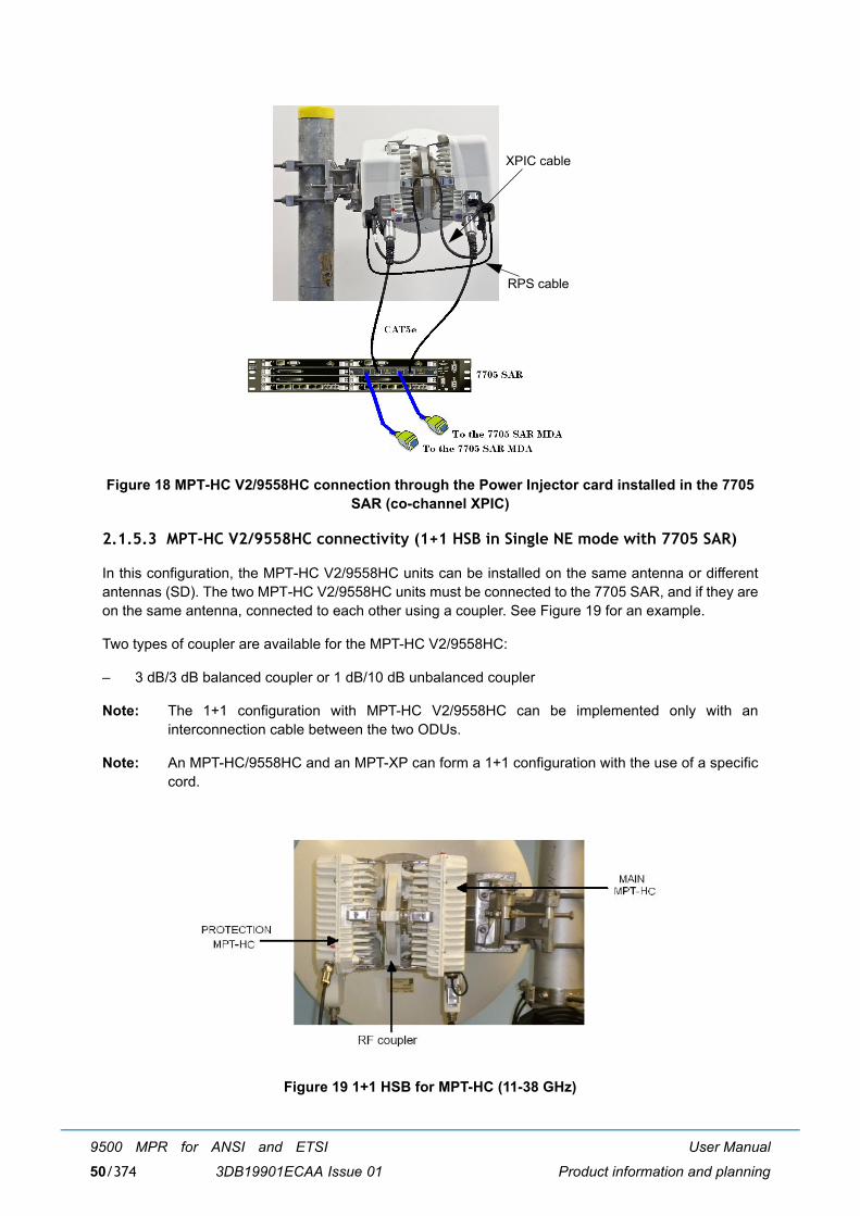
User Manual
Product information and planning
9500 MPR for ANSI and ETSI
3DB19901ECAA Issue 0150/374
Figure 18 MPT-HC V2/9558HC connection through the Power Injector card installed in the 7705 SAR (co-channel XPIC)
2.1.5.3 MPT-HC V2/9558HC connectivity (1+1 HSB in Single NE mode with 7705 SAR)
In this configuration, the MPT-HC V2/9558HC units can be installed on the same antenna or differentantennas (SD). The two MPT-HC V2/9558HC units must be connected to the 7705 SAR, and if they areon the same antenna, connected to each other using a coupler. See Figure 19 for an example.
Two types of coupler are available for the MPT-HC V2/9558HC:
� 3 dB/3 dB balanced coupler or 1 dB/10 dB unbalanced coupler
Note: The 1+1 configuration with MPT-HC V2/9558HC can be implemented only with aninterconnection cable between the two ODUs.
Note: An MPT-HC/9558HC and an MPT-XP can form a 1+1 configuration with the use of a specificcord.
Figure 19 1+1 HSB for MPT-HC (11-38 GHz)
XPIC cable
RPS cable

User Manual
Product information and planning
9500 MPR for ANSI and ETSI
3DB19901ECAA Issue 01 51/374
2.1.6 MPT-XP
MPT-XP is similar to MPT-HC V2 from architecture standpoint. The differences are:
MPT-XP is a very high power version of the MPT-HC V2.
Provides +7 dB of additional transmit power as compared to equivalent MPT-HC V2.
The power is provided from the MPT Extended Power Unit to the MPT-XP Data+DC connector.
The MPT-XP is frequency dependent.
Figure 20 MPT-XP
2.1.6.1 MPT-XP connectivity (1+0 configuration)
The MPT-XP can be connected to the GEthernet Generic Device through:
� Electrical interface
or
� Optical interface (an optional SFP must be installed in the MPT-XP).
2.1.6.1.1 Electrical interface
The MPT-XP is connected to a MPT Extended Power unit through one electrical Ethernet cable.
The maximum cable length is 100 m.
Figure 21 shows the connections used with the MPT Extended Power Unit.
The MPT Extended Power unit is an indoor device that is installed in a 19-inch or 21-inch rack.

User Manual
Product information and planning
9500 MPR for ANSI and ETSI
3DB19901ECAA Issue 0152/374
Figure 21 MPT-XP connection through the MPT Extended Power Unit

User Manual
Product information and planning
9500 MPR for ANSI and ETSI
3DB19901ECAA Issue 01 53/374
2.1.6.1.2 Optical interface
One Optical Ethernet cable connects the MPT-XP to the GEthernet Generic Device and one coaxial cableconnects the MPT-XP to MPT Extended Power Unit, or office power.
The maximum cable length is up to 300 m. For longer distances, please contact Product Management.
Figure 22 shows the connections used with the MPT Extended Power Unit.
Figure 22 MPT-XP connection (optical cable for traffic and coaxial cable to MPT ExtendedPower Unit)
2.1.6.2 MPT-XP connectivity (co-channel XPIC configuration)
In this configuration, the MPT-XP units must be installed on the OMT that is directly connected to theantenna. The two MPT-XP units must be connected to the Indoor Section as explained in paragraph2.1.6.1.
The two MPT-XP units must also be interconnected through two terminated cables (XPIC and RPScables) as shown in Figure 23.
Note: The extra length of the RPS and XPIC cables must be bound by using tie-wraps, either on the pole or on the other cables coming from the ODUs.

User Manual
Product information and planning
9500 MPR for ANSI and ETSI
3DB19901ECAA Issue 0154/374
Figure 23 MPT-XP connection through the MPT Extended Power Unit (co-channel XPIC)
2.1.6.3 MPT-XP connectivity (1+1 HSB in Single NE mode with 7705 SAR)
In this configuration, the MPT-XP units can be installed on the same antenna or different antennas (SD).The two MPT-XP units must be connected to the 7705 SAR, and if they are on the same antenna,connected to each other using a coupler. See Figure 24 for an example.
Two types of coupler are available for the MPT-XP:
� 3 dB/3 dB balanced coupler or 1 dB/10 dB unbalanced coupler
Note: The 1+1 configuration with MPT-XP can be implemented only with an interconnection cablebetween the two ODUs.
Note: An MPT-HC and an MPT-XP can form a 1+1 configuration with the use of a specific cord.
XPIC cable
RPS cable

User Manual
Product information and planning
9500 MPR for ANSI and ETSI
3DB19901ECAA Issue 01 55/374
Figure 24 1+1 HSB for MPT-XP (11-38 GHz)
2.1.7 MPR-E: MPT-MC
MPT-MC is similar to MPT-HC V2 from architecture standpoint. The only differences are:
� MPT-MC cannot be connected in optical -> 100m length cable limitation.
� MPT-MC does not support the XPIC configuration.
Figure 25 MPT-MC

User Manual
Product information and planning
9500 MPR for ANSI and ETSI
3DB19901ECAA Issue 0156/374
2.1.7.1 MPT-MC connectivity
The MPT-MC is connected to a Power Injector through one electrical Ethernet cable.
The max cable length is 100 m.
In Figure 26 and Figure 27 are shown the connections implemented with the two available PowerInjectors.
The Power Injector box is an indoor device to be installed in a 19-inch 21-inch rack.
The Power Injector card is a unit to be installed in a 7705 SAR.
Figure 26 MPT-MC connection through the Power Injector Box
Figure 27 MPT-MC connection through the Power Injector card installed in the 7705 SAR

User Manual
Product information and planning
9500 MPR for ANSI and ETSI
3DB19901ECAA Issue 01 57/374
2.1.8 Antennas
Antennas for direct-mounting an MPR-e are available in diameters from 0.3 m to 1.8 m, depending on thefrequency band.
A polarization rotator is included within the antenna collar, and direct-mounting equal or unequal losscouplers are available for single-antenna protected operation.
Antenna mounts are designed for use on industry-standard 114 mm OD pipe-mounts.
An MPR-e can also be used with standard antennas via a remote-mount kit and flexible waveguide.
Note: The MPR-e can also be mounted on most existing Melodie or AWY integrated antennas. Pleasecontact Alcatel-Lucent technical support for details.
2.2 MPR-E: radio capacity, channeling and modulation (MPT-HC V2/MPT-MC/MPT-XP)
Table 5. MPR-E modem profiles (static modulation)
Channel Spacing(MHz)
FCM Mode
ETSI Class
# E1(TDM2TDM)
Typical mean Ethernet Throughput
(any length: 64-1518 bytes)
3.5
QPSK 2 2 4.8 Mbit/s
8PSK 2 3 7.4 Mbit/s
16 QAM 4 4 9.3 Mbit/s
32 QAM 4 5 11.5 Mbit/s
64 QAM 5b 6 14.3 Mbit/s
7
QPSK 2 4 9.3 Mbit/s
8PSK 2 6 14.1 Mbit/s
16 QAM 4 9 20.2 Mbit/s
32 QAM 4 11 24.9 Mbit/s
64 QAM 5b 14 30.3 Mbit/s
128 QAM 5b 16 36.1 Mbit/s
256 QAM 6a 19 41.3 Mbit/s

User Manual
Product information and planning
9500 MPR for ANSI and ETSI
3DB19901ECAA Issue 0158/374
14
QPSK 2 9 20.4 Mbit/s
8PSK 2 14 30.6 Mbit/s
16 QAM 4 19 41.6 Mbit/s
32 QAM 4 23 51.1 Mbit/s
64 QAM 5b 29 62.8 Mbit/s
128 QAM 5b 34 74.2 Mbit/s
256 QAM 6a 41 87.4 Mbit/s
28
QPSK 2 19 41.9 Mbit/s
QPSK 2 (Note1) 20 43.8 Mbit/s
8PSK 2 29 62.7 Mbit/s
16 QAM 4 39 84.2 Mbit/s
16 QAM 4 (Note1) 41 87.9 Mbit/s
32 QAM 4 50 107.7 Mbit/s
64 QAM 5b 60 129.0 Mbit/s
128 QAM 5b 71 152.4 Mbit/s
256 QAM 6a 85 180.7 Mbit/s
30 MHz128 QAM n.a 76 162.8 Mbit/s
256 QAM n.a 87 185.3 Mbit/s
40 (NB2) 64 QAM 5b 88 186.6 Mbit/s
128 QAM 5b 104 220.6 Mbit/s
50 (NB4)
64 QAM n.a 110 234.2 Mbit/s
128 QAM n.a 130 276.3 Mbit/s
256 QAM n.a 148 314.4 Mbit/s
56
QPSK 2 (Note1) 37 80.5 Mbit/s
8PSK 2 (Note1) 56 120.2 Mbit/s
16 QAM 4 75 159.9 Mbit/s
16 QAM 4 (Note1) 76 161.9 Mbit/s
32 QAM 4 92 196.2 Mbit/s
64 QAM 5b 119 252.6 Mbit/s
128 QAM 5b 141 298.6 Mbit/s
256 QAM (NB2) 6a 160 339.8 Mbit/s
Channel Spacing(MHz)
FCM Mode
ETSI Class
# E1(TDM2TDM)
Typical mean Ethernet Throughput
(any length: 64-1518 bytes)

User Manual
Product information and planning
9500 MPR for ANSI and ETSI
3DB19901ECAA Issue 01 59/374
Note: Unified mask.
Note: Applicable only for 6 GHz and 11 GHz RF bands.
Note: QPSK can be also named 4 QAM.
Note: 50MHz available @ 23 GHz for Mexican market.
Table 6. MPR-E XPIC modem profiles for MPT-HC V2 and MPT-XP only (static modulation)
Note: 50MHz available @ 23 GHz for Mexican market.
Table 7. MPR-E modem profiles (adaptive modulation)
Channel Spacing
(MHz)
FCM Mode
ETSI Class
# E1(TDM2TDM)
# STM-1(SDH2SDH)
Typical mean Ethernet Throughput
(any length: 64-1518 bytes)
7
64 QAM 5 14 0 30.603 Mbit/s
128 QAM 5 16 0 36.652 Mbit/s
256 QAM 6 19 0 41.399 Mbit/s
14
64 QAM 5 29 0 63.901 Mbit/s
128 QAM 5 34 0 75.788 Mbit/s
256 QAM 6 39 0 85.279 Mbit/s
28
64 QAM 5b 60 0 129.001 Mbit/s
128 QAM 5b 72 0 152.593 Mbit/s
256 QAM 6b 79 1 168.777 Mbit/s
40
64 QAM 5b 88 1 186.976 Mbit/s
128 QAM 5b 104 1 220.726 Mbit/s
256 QAM 6a 117 1 248.010 Mbit/s
50 (NB1)128 QAM n.a. 173 1 276.463 Mbit/s
256 QAM n.a. 194 2 310.272 Mbit/s
56
64 QAM 5b 119 1 252.693 Mbit/s
128 QAM 5b 141 1 298.753 Mbit/s
256 QAM 6b 160 2 339.834 Mbit/s
Channel Spacing(MHz)
ACM ModeReference
ETSI Class
Modulation range Ethernet guaranteed rate(Max) (Mbps)
3.5QPSK 2 QPSK to 64 QAM 4.8 Mbit/s
16 QAM 4 16 QAM to 64 QAM 9.3 Mbit/s

User Manual
Product information and planning
9500 MPR for ANSI and ETSI
3DB19901ECAA Issue 0160/374
Note: Unified mask.
Table 8. MPR-E XPIC modem profiles for MPT-HC V2 and MPT-XP only (adaptive modulation)
7
QPSK 2 QPSK to 256 QAM 9.3 Mbit/s
16 QAM 4 16 QAM to 256 QAM 20.2 Mbit/s
32 QAM 4 32 QAM to 256 QAM 24.9 Mbit/s
64 QAM 5b 64 QAM to 256 QAM 30.3 Mbit/s
14
QPSK 2 QPSK to 256 QAM 20.4 Mbit/s
16 QAM 4 16 QAM to 256 QAM 41.6 Mbit/s
32 QAM 4 32 QAM to 256 QAM 51.1 Mbit/s
64 QAM 5b 64 QAM to 256 QAM 62.8 Mbit/s
28
QPSK 2 QPSK to 256 QAM 41.9 Mbit/s
QPSK 2 (NB2) QPSK to 256 QAM 43.8 Mbit/s
16 QAM 4 16 QAM to 256 QAM 84.2 Mbit/s
16 QAM 4 (NB2) 16 QAM to 256 QAM 87.9 Mbit/s
32 QAM 4 32 QAM to 256 QAM 107.7 Mbit/s
64 QAM 5b 64 QAM to 256 QAM 129.0 Mbit/s
30QPSK n.a. QPSK to 256QAM 43.8 Mbit/s
64 QAM n.a. 64QAM to256QAM 138.0 Mbit/s
40 64 QAM 5b 64 QAM to 256 QAM 186.6 Mbit/s
56
QPSK 2 (NB1) QPSK to 256 QAM 80.5 Mbit/s
16 QAM 4 16 QAM to 256 QAM 159.9 Mbit/s
16 QAM 4 (NB1) 16 QAM to 256 QAM 161.9 Mbit/s
32 QAM 4 32 QAM to 256 QAM 196.2 Mbit/s
64 QAM 5b 64 QAM to 256 QAM 252.6 Mbit/s
Channel Spacing(MHz)
ACM ModeReference
ETSI Class
Modulation range Ethernet guaranteed rate(Max) (Mbps)
7
QPSK 2 (NB1) QPSK to 256 QAM 9.381 Mbit/s
16 QAM 4 (NB1) 16 QAM to 256 QAM 20.326 Mbit/s
64 QAM 5 64 QAM to 256 QAM 30.420 Mbit/s
Channel Spacing(MHz)
ACM ModeReference
ETSI Class
Modulation range Ethernet guaranteed rate(Max) (Mbps)

User Manual
Product information and planning
9500 MPR for ANSI and ETSI
3DB19901ECAA Issue 01 61/374
Note: Unified mask.
50MHz available @ 23 GHz for Mexican market.
2.3 MPR-A: Radio capacity, channeling and modulation (MPT-HC V2 /MPT-XP/9558HC)
Table 9. MPR-A Modem Profiles (Static Modulation)
14
QPSK 2 (NB1) QPSK to 256 QAM 20.501 Mbit/s
16 QAM 4 (NB1) 16 QAM to 256 QAM 41.696 Mbit/s
64 QAM 5 64 QAM to 256 QAM 62.933 Mbit/s
28
QPSK 2 (NB1) QPSK to 256 QAM 43.897 Mbit/s
16 QAM 4 (NB1) 16 QAM to 256 QAM 88.093 Mbit/s
64 QAM 5 64 QAM to 256 QAM 129.263 Mbit/s
40 64 QAM 5 64 QAM to 256 QAM 187.355 Mbit/s
50 (NB2) 64 QAM n.a. 64 QAM to 256 QAM 234.700 Mbit/s
56
QPSK 2 (NB1) QPSK to 256 QAM 80.761 Mbit/s
16 QAM 4 (NB1) 16 QAM to 256 QAM 162.286 Mbit/s
64 QAM 5 64 QAM to 256 QAM 253.206 Mbit/s
Channel Spacing(MHz)
FCM Mode # T1/DS1(TDM2TDM)
Typical Ethernet Throughput (1518 bytes)
5 128 QAM 14 24.36 Mb/s
10
4 QAM 8 14.03 Mb/s
8 QAM 12 21.14 Mb/s
16 QAM 17 28.28 Mb/s
32 QAM 21 35.24 Mb/s
64 QAM 27 44.74 Mb/s
128 QAM 32 52.70 Mb/s
256 QAM 37 60.31 Mb/s

User Manual
Product information and planning
9500 MPR for ANSI and ETSI
3DB19901ECAA Issue 0162/374
Table 10. MPR-A XPIC modem profiles (static modulation)
Table 11. MPR-A modem profiles (adaptive modulation)
30
4 QAM 27 43.85 Mb/s
8 QAM 40 65.51 Mb/s
16 QAM 54 87.45 Mb/s
32 QAM 67 108.75 Mb/s
64 QAM 86 138.02 Mb/s
128 QAM 101 162.88 Mb/s
256 QAM 116 185.37 Mb/s
40
4 QAM 37 59.48 Mb/s
64 QAM 117 186.98 Mb/s
128 QAM 138 220.63 Mb/s
256 QAM 157 251.10 Mb/s
50
4 QAM 46 74.59 Mb/s
64 QAM 146 234.23 Mb/s
128 QAM 173 276.37 Mb/s
256 QAM 197 314.46 Mb/s
Channel Spacing(MHz)
FCM Mode # T1/DS1(TDM2TDM)
Typical Ethernet Throughput (1518 bytes)
30128 QAM 102 162.88 Mb/s
256 QAM 114 185.37 Mb/s
40128 QAM 138 220.63 Mb/s
256 QAM 155 251.10 Mb/s
50128 QAM 173 276.37 Mb/s
256 QAM 194 314.46 Mb/s
Channel Spacing(MHz)
ACM ModeReference
# T1/DS1(TDM2TDM)
Typical EthernetThroughput(1518 bytes)
5
4 QAM 3 6.34 Mb/s
8 QAM 5 9.70 Mb/s
16 QAM 7 13.03 Mb/s
32 QAM 9 16.14 Mb/s
64 QAM 12 20.59 Mb/s

User Manual
Product information and planning
9500 MPR for ANSI and ETSI
3DB19901ECAA Issue 01 63/374
Table 12. MPR-A XPIC modem profiles (adaptive modulation)
10
4 QAM 8 14.03 Mb/s
8 QAM 12 21.14 Mb/s
16 QAM 17 28.28 Mb/s
32 QAM 21 35.24 Mb/s
64 QAM 27 44.74 Mb/s
128 QAM 32 52.70 Mb/s
256 QAM 37 60.31 Mb/s
30
4 QAM 27 43.85 Mb/s
8 QAM 40 65.51 Mb/s
16 QAM 54 87.45 Mb/s
32 QAM 67 108.75 Mb/s
64 QAM 86 138.02 Mb/s
128 QAM 101 162.88 Mb/s
256 QAM 116 185.37 Mb/s
40
4 QAM 37 59.48 Mb/s
64 QAM 117 186.97 Mb/s
128 QAM 138 220.63 Mb/s
256 QAM 157 251.09 Mb/s
50
4 QAM 46 74.59 Mb/s
64 QAM 146 234.22 Mb/s
128 QAM 173 276.37 Mb/s
256 QAM 197 314.46 Mb/s
Channel Spacing(MHz)
FCM Mode # T1/DS1(TDM2TDM)
Typical Ethernet Throughput (1518 bytes)
30
64 QAM 86 138.02 Mb/s
128 QAM 101 162.88 Mb/s
256 QAM 116 185.37 Mb/s
Channel Spacing(MHz)
ACM ModeReference
# T1/DS1(TDM2TDM)
Typical EthernetThroughput(1518 bytes)

User Manual
Product information and planning
9500 MPR for ANSI and ETSI
3DB19901ECAA Issue 0164/374
2.4 Standard features
Standard features include more radio and site scalability and flexibility for installation teams:
� Limited need for factory presetting of channel frequency or bandwidth
� Supports cellular mobile networks, and microcellular network back and common carrier, privatecarrier and data networks, and utility haul applications
� Outdoor Unit capacity- and modulation-independent
� Outdoor Unit can support either split-mount or full-outdoor architecture with the same hardware
� Adaptive packet transport improves performance for priority services
� Output power agility
� ATPC
� XPIC
� Adaptive Modulation
� Electrical/Optical GE interfaces
� QoS on the Ethernet traffic
� Software-based configuration
� Packet throughput booster for enhanced bandwidth
2.5 Radio configurations
The following radio configurations are available:
� 1+0 full outdoor
� 1+0 repeater (with MPT-HC V2, MPT-XP, AND 9558HC only)
� co-channel XPIC full outdoor (with MPT-HC V2, MPT-XP, AND 9558HC only) used to establish a 2x (1+0) radio link.
� 1+1 HSB (with MPT-HC V2, MPT-XP, AND 9558HC only) when in Single NE mode with 7705 SARconfiguration (with MPR-e 4.1.0)
40
64 QAM 117 186.97 Mb/s
128 QAM 138 220.63 Mb/s
256 QAM 157 251.10 Mb/s
50
64 QAM 146 234.22 Mb/s
128 QAM 173 276.37 Mb/s
256 QAM 197 314.46 Mb/s

User Manual
Product information and planning
9500 MPR for ANSI and ETSI
3DB19901ECAA Issue 01 65/374
2.6 Environmental and electrical characteristics
� General characteristics (MPT-HC V2/MPT-MC/MPT-XP/9558HC) (par. 2.6.1)
� MPR-E: MPT-HC V2 characteristics (par. 2.6.2)
� MPR-E: MPT-MC characteristics (par. 2.6.3)
� MPR-E: MPT-XP characteristics (par. 2.6.4)
� MPR-A: MPT-HC V2/9558HC characteristics (par. 2.6.5)
� MPR-A: MPT-XP characteristics (par. 2.6.6)
� Radio performances (par. 2.6.7)
� General characteristics (Power Injector) (par. 2.6.8)
� General characteristics (MPT power unit) (par. 2.6.9)
� General characteristics (MPT extended power unit) (par. 2.6.12)
2.6.1 General characteristics (MPT-HC V2/MPT-MC/MPT-XP/9558HC)
General with MPT-HC V2/MPT-XP/9558HC
Operating Frequency Range 5.8 - 38 GHz
Max. Ethernet throughput 340 Mb/s
Bandwidth MPR-E: up to 56 MHz
MPR-A: up to 50 MHz
Modulation Options in FCM QPSK, 8PSK, 16 QAM, 32 QAM, 64 QAM, 128 QAM, 256 QAM
Adaptive Modulation QPSK, 8PSK, 16 QAM, 32 QAM, 64 QAM, 128 QAM, 256 QAM
General with MPT-MC (MPR-E)
Operating Frequency Range 6 - 38 GHz
Max. Ethernet throughput 340 Mbps
Bandwidth up to 56 MHz
Modulation Options in FCM QPSK, 8PSK, 16 QAM, 32 QAM, 64 QAM, 128 QAM, 256 QAM
Adaptive Modulation QPSK, 8PSK, 16 QAM, 32 QAM, 64 QAM, 128 QAM, 256 QAM
Radio Path Protection Options
Non Protected, 1+0
Standards Compliance
EMC EN 301 489-1, EN 301 489-4, EN 55022 Class B
Stationary use ETS 300 019, Class 4.1

User Manual
Product information and planning
9500 MPR for ANSI and ETSI
3DB19901ECAA Issue 0166/374
2.6.2 MPR-E: MPT-HC V2 characteristics
2.6.2.1 5.8 to 13 GHz
Storage ETS 300 019, Class 1.2
Transportation ETS 300 019, Class 2.3
Safety IEC 60950-1/EN 60950-1
Radio Frequency EN 302 217 Classes 2, 4 & E5
Water Ingress IEC 60529 (IPX6)
Environmental
Operating Temperature
(Guaranteed)
-33° to +55°C
Startup temperature from lowtemperature
-40°C
Humidity
(Guaranteed)
0 to 100%
Management
TMN In-band Extension of the DCN over the Ethernet traffic interfaces
5.8 GHz L6 GHz U6 GHz 7 GHz 8 GHz 10.5 GHz 11 GHz 13 GHz
System
Frequency Range, GHz 5.725,5 -5.849,5
5.930 - 6.420
6.425 - 7.11
7.125 - 7.9
7.725 - 8.5
10.000-10.684
10.7 - 11.7
12.75 - 13.25
T-R Spacings supported, MHz 64 252.04 160; 340
154; 161; 168; 175; 196; 245
119; 126;
151.614; 208;
211.4; 213,5; 266;
294.44; 300; 310;
305.56; 311.32
91; 350
490; 530
266
Antenna Interface
Waveguide Type WR137 WR137 WR137 WR112 WR112 WR75 WR75 WR62
Input voltage range -28 V to -58 V
Typical power consumption (MPT-HC V2)
37 W

User Manual
Product information and planning
9500 MPR for ANSI and ETSI
3DB19901ECAA Issue 01 67/374
2.6.2.2 15 to 38 GHz
Guaranteed power consumption (MPT-HC V2)
39 W
Typical power consumption (MPT-HC V2 with RPS module)
38 W
Guaranteed power consumption (MPT-HC V2 with RPS module)
40 W
Typical power consumption (MPT-HC V2 with XPIC-RPS module)
46 W
Guaranteed power consumption (MPT-HC V2 with XPIC-RPS module)
48 W
15 GHz 18 GHz 23 GHz 25 GHz 38 GHz
System
Frequency Range, GHz 14.4 - 15.35
17.7 - 19.7
21.2 - 23.632
24.52 - 26.483
37.0 - 39.46
T-R Spacings supported, MHz 308; 315; 322; 420; 475; 490; 640; 644;
728
1008; 1010; 1560; 340
1008; 1050; 1200; 1232
1008 700; 1260
Antenna Interface
Waveguide Type WR62 WR42 WR42 WR42 WR28
Input voltage range -28 V to -58 V
Typical power consumption (MPT-HC V2) 37 W
Guaranteed power consumption (MPT-HC V2) 39 W
Typical power consumption (MPT-HC V2 with RPS module)
38 W
Guaranteed power consumption (MPT-HC V2 with RPS module)
40 W
Typical power consumption (MPT-HC V2 with XPIC-RPS module)
46 W
Guaranteed power consumption (MPT-HC V2 with XPIC-RPS module)
48 W

User Manual
Product information and planning
9500 MPR for ANSI and ETSI
3DB19901ECAA Issue 0168/374
2.6.3 MPR-E: MPT-MC characteristics
2.6.3.1 6 to 13 GHz
2.6.3.2 15 to 38 GHz
L6 GHz U6 GHz 7 GHz 8 GHz 11 GHz 13 GHz
System
Frequency Range, GHz 5.930 - 6.420
6.420-7.115
7.125 - 7.9
7.725 - 8.5
10.7 - 11.7
12.75 - 13.25
T-R Spacings supported, MHz 252.04 160; 340
154;161;168;196;245
119; 126; 151.614;
208; 213,5; 266;
294.44; 305.56; 311.32
490; 530
266
Antenna Interface
Waveguide Type WR137 WR137 WR112 WR112 WR75 WR62
Typical power consumption 38 W
Guaranteed power consumption 40 W
15 GHz 18 GHz 23 GHz 25 GHz 38 GHz
System
Frequency Range, GHz 14.4 - 15.35
17.7 - 19.7
21.2 - 23.632
24.52 - 26.483
37.0 - 39.46
T-R Spacings supported, MHz 420;490;
1008;1010;1560
1008; 1050;1200;1232
1008 1260
Antenna Interface
Waveguide Type WR62 WR42 WR42 WR42 WR28
Typical power consumption 38 W
Guaranteed power consumption 40 W

User Manual
Product information and planning
9500 MPR for ANSI and ETSI
3DB19901ECAA Issue 01 69/374
2.6.4 MPR-E: MPT-XP characteristics
2.6.4.1 MPT-XP 6 to 8 GHz
2.6.5 MPR-A: MPT-HC V2/9558HC characteristics
2.6.5.1 5.8 to 11 GHz
L6 GHz U6 GHz 7 GHz 8 GHz
System
Frequency Range, GHz 5.930 - 6.420 6.425 - 7.11 7.125 - 7.9 7.725 - 8.5
T-R Spacings supported, MHz 252.04 160; 340 154; 161; 168; 175; 196; 245
119; 126; 151.614; 208; 211.4; 213,5; 266; 294.44;
300; 310; 305.56; 311.32
Antenna Interface
Waveguide Type WR137 WR137 WR112 WR112
Typical power consumption (MPT-XP) 67 W
Guaranteed power consumption (MPT-XP) 70 W
Typical power consumption (MPT-XP with RPS module)
67 W
Guaranteed power consumption (MPT-XP with RPS module)
70 W
Typical power consumption (MPT-XP with XPIC-RPS module)
73 W
Guaranteed power consumption (MPT-XP with XPIC-RPS module)
78 W
5.8 GHz L6 GHz L6 GHz 7 GHz 8 GHz 11 GHz
System
Frequency Range, GHz 5.725 -5.850
5.930 -6.420
6.420 -7.115
7.125 - 7.9 7.725 - 8.5 10.7 - 11.7
T-R Spacings supported MHz 64 252 160, 340 175 300 490/500
Antenna Interface
Waveguide Type WR137 WR137 WR137 WR112 WR112 WR75
Input voltage range -28 Vdc to -58 Vdc
Typical power consumption (MPT-HC V2/9558HC)
37 W
Guaranteed power consumption (MPT-HC V2/9558HC)
39 W

User Manual
Product information and planning
9500 MPR for ANSI and ETSI
3DB19901ECAA Issue 0170/374
2.6.5.2 15 to 38 GHz
Typical power consumption (MPT-HC V2 with RPS module)
38 W
Guaranteed power consumption (MPT-HC V2 with RPS module)
40 W
Typical power consumption (MPT-HC V2 with XPIC-RPS module)
46 W
Guaranteed power consumption (MPT-HC V2 with XPIC-RPS module)
48 W
15 GHz 18 GHz 23 GHz 38 GHz
System
Frequency Range, GHz 14.5 - 15.144 17.7 - 19.7 21.2 - 23.6 38.6 - 40.0
T-R Spacings supported MHz 475 1560 1200/1232 700
Antenna Interface
Waveguide Type WR62 WR42 WR42 WR28
Input voltage range -28 Vdc to -58 Vdc
Typical power consumption (MPT-HC V2)
37 W
Guaranteed power consumption (MP--HC V2)
39 W
Typical power consumption (MPT-HC V2 with RPS module)
38 W
Guaranteed power consumption (MP--HC V2 with RPS module)
40 W
Typical power consumption (MPT-HC V2 with XPIC-RPS module)
46 W
Guaranteed power consumption (MP--HC V2 with XPIC-RPS module)
48 W

User Manual
Product information and planning
9500 MPR for ANSI and ETSI
3DB19901ECAA Issue 01 71/374
2.6.6 MPR-A: MPT-XP characteristics
2.6.6.1 MPT-XP 6 to 8 GHz
2.6.7 Radio performances
The radio performance specifications are provided in the �Technical Description� document.
2.6.8 General characteristics (Power Injector)
L6 GHz U6 GHz 7 GHz 8 GHz
System
Frequency Range, GHz 5.930 - 6420 6.420 - 7.115 7.125 - 7.9 7.725 - 8.5
T-R Spacings supported, MHz 252 160, 340 175 300
Antenna Interface
Waveguide Type WR137 WR137 WR112 WR112
Typical power consumption (MPT-XP) 67 W
Guaranteed power consumption (MPT-XP)
70 W
Typical power consumption (MPT-XP with RPS module)
67 W
Guaranteed power consumption (MPT-XP with RPS module)
70 W
Typical power consumption (MPT-XP with XPIC-RPS module)
73 W
Guaranteed power consumption (MPT-XP with XPIC-RPS module)
78 W
Power Injector
Input Voltage range -38.4 to -57.6 Vdc
Standards Compliance (Power Injector)
EMC EN 301 489-1, EN 301 489-4, EN 55022 Class B
Stationary use ETS 300 019 1-3, Class 3.2
Storage ETS 300 019 2-1, Class 1.2
Transportation ETS 300 019 2-2, Class 2.3
Safety EN 60950
Environmental

User Manual
Product information and planning
9500 MPR for ANSI and ETSI
3DB19901ECAA Issue 0172/374
2.6.9 General characteristics (MPT power unit)
2.6.10 MPR-E: Maximum allowed cable lengths for MPT Power Unit
Operating Temperature
(Guaranteed)
-40° to +65°C
Humidity
(Guaranteed)
0 to 95%, non-condensing
Standards Compliance (MPT Power Unit)
EMC EN 301 489-1, GR-1089 Class A
Storage ETS 300 019, Class 1.2, GR-3108
Transportation ETS 300 019 1-2, Class 2.3, GR-3108-CORE
Safety EN 60950, UL-60950
Environmental
Operating Temperature
(Guaranteed)
-40° to +65° C
Start up temperature from lowtemperature
-40° C
Humidity
(Guaranteed)
0 to 95%
Cable type Coaxial cable 1AC001100022
Power only, Data optical cable
Coaxial cable 1AC041350001
Power only, data optical cable
Configuration Required power Maximum length Maximum length
MPT-HC V2 42 W 510 m 220 m
MPT-HC V2 with XPIC 47 W 440 m 190 m
Constraint 1 Maximum current in the Ethernet transformer < 1.8 AMaximum current limit for the Power Unit: 1.8 A
Constraint 2 Minimum MPT-HC PSU input voltage > 28 V
Constraint 3 Data traffic only with optical cable

User Manual
Product information and planning
9500 MPR for ANSI and ETSI
3DB19901ECAA Issue 01 73/374
2.6.11 MPR-A: Maximum allowed cable lengths for MPT Power Unit
2.6.12 General characteristics (MPT extended power unit)
Cable type Coaxial cable1AB350440001Power only, dataon optical cable
Configuration Required power Maximum length
MPT-HC V2 42 W 300 m
MPT-HC V2 with XPIC 47 W 300 m
Constraint 1 Maximum current in the Ethernet transformer < 1.8 AMaximum current limit for the Power Unit: 1.8 A
Constraint 2 Minimum MPT-HC PSU input voltage > 28 V
Constraint 3 Data traffic only with optical cable
Standards Compliance (Power Extractor)
EMC EN 301 489-1, GR-1089 Class A
Storage ETS 300 019, Class 1.2, GR-3108
Transportation ETS 300 019 1-2, Class 2.3, GR-3108-CORE
Safety EN 60950, UL-60950
Environmental
Operating Temperature
(Guaranteed)
-40° to +65° C
Start up temperature from lowtemperature
-40° C
Humidity
(Guaranteed)
0 to 95%

User Manual
Product information and planning
9500 MPR for ANSI and ETSI
3DB19901ECAA Issue 0174/374
2.6.13 MPR-E: Maximum allowed cable length for MPT Extended Power Unit
Cable type Ethernet UTP 5E with outer screen and
braid. Power and Data on
Ethernet cable
Ethernet UTP 5E with outer screen and
braid. Power only, Data
optical cable
Coaxial cable 1AC001100022
Power only, Data optical
cable
Coaxial cable 1AC041350001
Power only, Data optical
cable
Configuration Maximum length
Maximum length
Maximum length
Maximum length
MPT-MC/HC 100 m 400 m 1100 m 500 m
MPT-HC V2 with XPIC 100 m 350 m 1000 m 440 m
MPT-XP 100 m 170 m 480 m 210 m
MPT-XP with XPIC 100 m 130 m 360 m 160 m
Constraint 1 Maximum current in Ethernettransformer < 1.8 A Maximum current limit for PowerUnit: 1.8 A
Maximum current limit for PowerUnit: 1.8 A
Constraint 2 Minimum MPT-HC PSU input voltage > 28 V, Minimum MPT-XP PSU inputvoltage > 36 V
Constraint 3 Data traffic onlywith Ethernetcable
Data traffic only with optical cable

User Manual
Product information and planning
9500 MPR for ANSI and ETSI
3DB19901ECAA Issue 01 75/374
2.6.14 MPR-A: Maximum allowed cable length for MPT Extended Power Unit
2.7 MPR-E parts lists
2.7.1 Indoor items
Table 13. MPR-E: Indoor items
Cable type Cat5E, 1AC016760006:Power and Data on Ethernet cable
Cat5E, 1AC016760006:Power only, Data on optical cable
Coaxial cable 1AB350440001:Power only, Data on optical cable
Configuration Maximum length Maximum length Maximum length
MPT-MC/HC 100 m 100 m 300 m
MPT-HC V2 with XPIC 100 m 100 m 300 m
MPT-XP 100 m 100 m 300 m
MPT-XP with XPIC 100 m 100 m 300 m
Constraint 1 Maximum current in Ethernet transformer <1.8 A Maximum current limit for Power Unit: 1.8 A
Maximum currentlimit for Power Unit:1.8 A
Constraint 2 Minimum MPT-HC PSU input voltage > 28 V, Minimum MPT-XP PSUinput voltage > 36 V
Constraint 3 Data traffic only withEthernet cable
Data traffic only withoptical cable
Name Part number Remarks
[A] Power Injector box 3CC50129AAXX To be installed in a 19-inch/21-inch rack toprovide the PFoE to the MPT-MC
[B] Power Injector card 3HE07152AAXX To be installed in a 7705 SAR shelf to providethe PFoE to the MPT-MC or to the MPT-HCV2
[B] Power Injector card 3CC50120AAXX To be installed in a 9500 MPR shelf to providethe PFoE to the MPT-MC or to the MPT-HCV2
[C] Bracket 3DB77008ACXX Bracket to be used to install the PowerInjector box in a 19-inch rack
[D] 21-inch Adapter kit 3CC50065AAAA Kit to be used with item [C, E, and F] to installthe Power Injector box, MPT Power Unit, andMPT Extended Power Unit in a 21-inch rack

User Manual
Product information and planning
9500 MPR for ANSI and ETSI
3DB19901ECAA Issue 0176/374
Table 14. MPR-E: CD-ROM software
2.7.2 MPT-HC V2/MPT-XP optical interface option
Table 15. MPR-E: MPT-HC V2/MPT-XP option
2.7.3 MPT-HC V2/MPT-XP external modules (option)
Table 16. MPR-E: MPT-HC V2/MPT-XP external modules
[E] MPT Power Unit 3CC50173AAXX To be installed in a 19-inch/21-inch rack toprovide the office power to the MPT-HC V2.Includes rack mounting bracket.
[F] MPT Extended Power Unit 3CC50174AAXX To be installed in a 19-inch/21-inch rack toprovide the PFoE or office power to theMPT-HC V2/ MPT-MC/MPT-XP. Includesrack mounting bracket.
[G] 250W 120/240V AC Power
Converter
3HE05838AA To be connected to a Power Injector Box(PIB) when an AC power source is required.
[H] 7705 SAR AC PowerConverter Pigtail O-Ring
3HE05837BA To connect the DC power terminal block onthe PIB to the AC power converter.
Name Part number
TCO Software Suite R4.10 DVD-ROM 3DB18971ADAA
SWP 9500 MPR HYBRID CD-ROM 3DB18969ADAA
SWP 9500 MPR PACKET CD-ROM 3DB18970ADAA
9500 MPR Rel 4.2.0 User Manual CD-ROM EN 3DB19902ACAA
Name Part number Remarks
SFP 1000Base-Sx 1AB38376000/3CC50167AAAA
Optical SFP module to be installed optionally in theMPR-e to provide the optical Gigabit Ethernet interface
SFP 1000Base-Lx 1AB383760002/3CC50168AAAA
Description Part number Remarks
RPS MODULE 3DB20117BAXX All frequency band for 1+1 configuration. The 1+1configuration is not available for MPR-e.
XPIC-RPS MODULE 3DB20116BAXX All frequency bands. This module is used for the XPICconfiguration.
3DB20116BBXX

User Manual
Product information and planning
9500 MPR for ANSI and ETSI
3DB19901ECAA Issue 01 77/374
2.7.4 MPT-HC V2 with internal diplexer
Table 17. MPR-E: MPT-HC V2 with internal diplexer
Band (GHz) Shifter (MHz) Tx sub-band Part number Tx frequency (MHz)
L6 252.04 1 3DB20441BAXX 5929.96-6050
1P 3DB20443BAXX 6182-6302.04
2 3DB20442BAXX 6047.96-6168
2P 3DB20444BAXX 6300-6420.04
U6 340 1 3DB20437BAXX 6420-6600
1P 3DB20439BAXX 6760-6940
2 3DB20438BAXX 6565-6745
2P 3DB20440BAXX 6905-7085
3 3DB20464BAXX 6595-6775
3P 3DB20465BAXX 6935-7115
11 530-490 1 3DB20371BAXX 10695-10955
1P 3DB20547BAXX 11205-11485
2 3DB20546BAXX 10935-11205
2P 3DB20548BAXX 11445-11705
13 266 1 3DB20372BAXX 12750-12865
1P 3DB20420BAXX 13016-13131
2 3DB20419BAXX 12861-12980
2P 3DB20421BAXX 13127-13246
15 308-315-322 1 3DB20466BAXX 14630-14766
1P 3DB20468BAXX 14945-15081
2 3DB20467BAXX 14759-14899
2P 3DB20469BAXX 15074-15215
420-475 1 3DB20373BAXX 14500-14724
1P 3DB20423BAXX 14920-15144
420 2 3DB20422BAXX 14710-14941
2P 3DB20424BAXX 15130-15361
490 1 3DB20425BAXX 14400-14635
1P 3DB20427BAXX 14890-15125
2 3DB20426BAXX 14625-14860
2P 3DB20428BAXX 15115-15350
640-644-728 1 3DB20448BAXX 14500-14700
1P 3DB20449BAXX 15144-15348

User Manual
Product information and planning
9500 MPR for ANSI and ETSI
3DB19901ECAA Issue 0178/374
18 1560 1 3DB20432BAXX 17700-18140
3DB20432BBXX 17700-18140.5
1P 3DB20433BAXX 19260-19700
3DB20433BBXX 19260-19700.5
340 1 3DB20549BAXX 18581-18700
1P 3DB20551BAXX 18920-19040
2 3DB20550BAXX 18701-18820
2P 3DB20552BAXX 19040-19160
1008-1010 1 3DB20374BAXX 17700-18201
1P 3DB20430BAXX 18710-19211
2 3DB20429BAXX 18180-18690
2P 3DB20431BAXX 19190-19700
23(NB1)
1200-1232 1 3DB20473BAXX 21198-21819
1P 3DB20475BAXX 22400-23019
1050-1200-1232
2 3DB20474BAXX 21781-22400
2P 3DB20476BAXX 22981-23600
1008 1 3DB20375BAXX 22000-22316
3DB20375BBXX 22000-22330
1P 3DB20471BAXX 23008-23324
3DB20471BBXX 23008-23338
2 3DB20470BAXX 22300-22600
2P 3DB20472BAXX 23308-23608
25 1008 1 3DB20376BAXX 24540-24997
1P 3DB20554BAXX 25548-26005
2 3DB20553BAXX 24994-25448
2P 3DB20555BAXX 26002-26456
2 3DB20553BBXX 24966-25448
2P 3DB20555BBXX 25974-26456
38 1260 1 3DB20458BAXX 37050-37620
1P 3DB20460BAXX 38310-38880
2 3DB20459BAXX 37618-38180
2P 3DB20461BAXX 38878-39440
Band (GHz) Shifter (MHz) Tx sub-band Part number Tx frequency (MHz)

User Manual
Product information and planning
9500 MPR for ANSI and ETSI
3DB19901ECAA Issue 01 79/374
2.7.5 MPT-MC with internal diplexer
Table 18. MPR-E: MPT-MC with internal diplexer
Band (GHz) Shifter (MHz) Tx sub-band Part number Tx frequency (MHz)
L6 252.04 1 3DB20838AAXX 5929.96-6050
1P 3DB20840AAXX 6182-6302.04
2 3DB20839AAXX 6047.96-6168
2P 3DB20841AAXX 6300-6420.04
11 490-530 1 3DB20874ABXX 10695-10955
1P 3DB20876ABXX 11205-11485
2 3DB20875ABXX 10935-11205
2P 3DB20877ABXX 11445-11705
13 266 1 3DB20818AAXX 12750-12865
1P 3DB20820AAXX 13016-13131
2 3DB20819AAXX 12861-12980
2P 3DB20821AAXX 13127-13246
15 420-475 1 3DB20822AAXX 14500-14724
1P 3DB20824AAXX 14920-15144
420 2 3DB20823AAXX 14710-14941
2P 3DB20825AAXX 15130-15361
490 1 3DB20826AAXX 14400-14635
1P 3DB20828AAXX 14890-15125
2 3DB20827AAXX 14625-14860
2P 3DB20829AAXX 15115-15350
640-644-728 1 3DB20897ABXX 14500-14710
1P 3DB20898ABXX 15144-15350
18 1560 1 3DB20864AAXX 17700-18140
3DB20864ABXX 17700-18140.5
1P 3DB20865AAXX 19260-19700
3DB20865ABXX 19260-19700.5
1008-1010 1 3DB20860AAXX 17700-18201
1P 3DB20862AAXX 18710-19211
2 3DB20861AAXX 18180-18690
3DB20861ABXX 18167-18690
2P 3DB20863AAXX 19190-19700
3DB20863ABXX 19176.5-19700
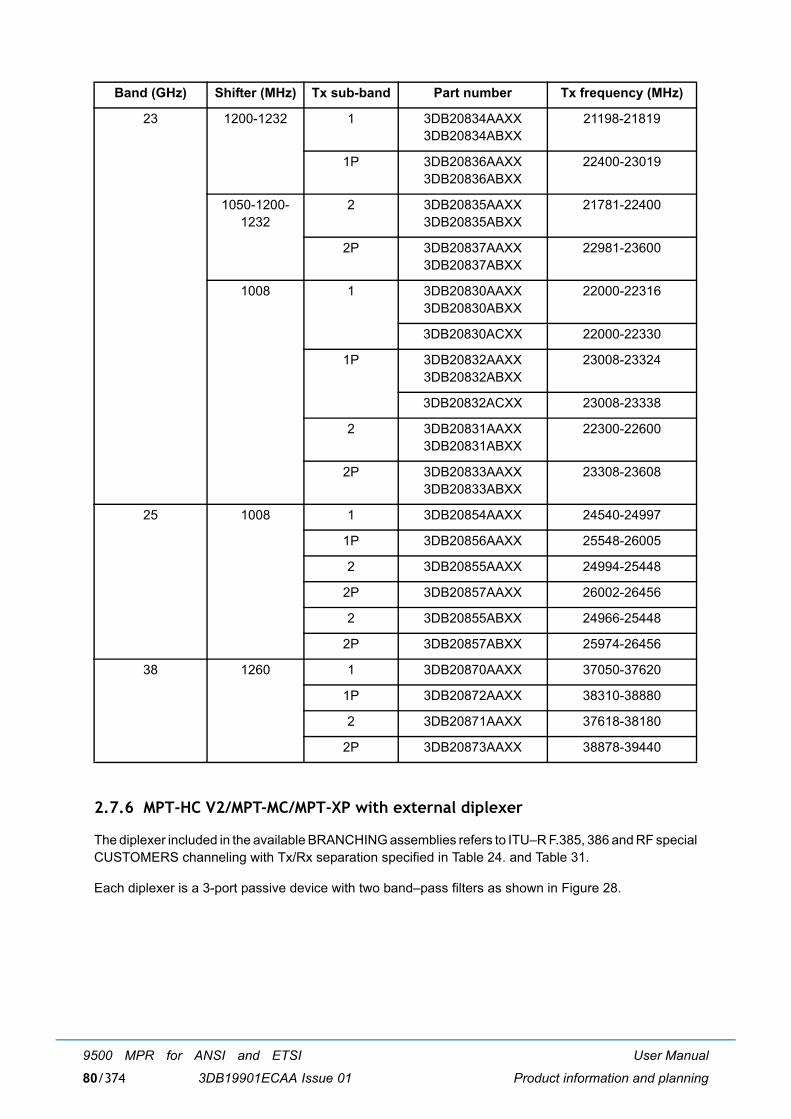
User Manual
Product information and planning
9500 MPR for ANSI and ETSI
3DB19901ECAA Issue 0180/374
2.7.6 MPT-HC V2/MPT-MC/MPT-XP with external diplexer
The diplexer included in the available BRANCHING assemblies refers to ITU�R F.385, 386 and RF specialCUSTOMERS channeling with Tx/Rx separation specified in Table 24. and Table 31.
Each diplexer is a 3-port passive device with two band�pass filters as shown in Figure 28.
23 1200-1232 1 3DB20834AAXX3DB20834ABXX
21198-21819
1P 3DB20836AAXX3DB20836ABXX
22400-23019
1050-1200-1232
2 3DB20835AAXX3DB20835ABXX
21781-22400
2P 3DB20837AAXX3DB20837ABXX
22981-23600
1008 1 3DB20830AAXX3DB20830ABXX
22000-22316
3DB20830ACXX 22000-22330
1P 3DB20832AAXX3DB20832ABXX
23008-23324
3DB20832ACXX 23008-23338
2 3DB20831AAXX3DB20831ABXX
22300-22600
2P 3DB20833AAXX3DB20833ABXX
23308-23608
25 1008 1 3DB20854AAXX 24540-24997
1P 3DB20856AAXX 25548-26005
2 3DB20855AAXX 24994-25448
2P 3DB20857AAXX 26002-26456
2 3DB20855ABXX 24966-25448
2P 3DB20857ABXX 25974-26456
38 1260 1 3DB20870AAXX 37050-37620
1P 3DB20872AAXX 38310-38880
2 3DB20871AAXX 37618-38180
2P 3DB20873AAXX 38878-39440
Band (GHz) Shifter (MHz) Tx sub-band Part number Tx frequency (MHz)

User Manual
Product information and planning
9500 MPR for ANSI and ETSI
3DB19901ECAA Issue 01 81/374
Figure 28 MPT-HC V2/MPT-MC/MPT-XP with external diplexer - diplexer as a 3-port passive device with two band�pass filters
The arrangement between each filter on the same branching device is shown in Figure 29.
Figure 29 MPT-HC V2/MPT-MC/MPT-XP with external diplexer - arrangement between each filter on the same branching device
WARNING: f1, f2, f3 and f4 frequencies of the branching filters refer to the extreme channel frequenciesand not to the cut-off frequencies of the filters.
2.7.6.1 External diplexer MPT-MC, MPT-HC V2, MPT-XP
Table 19. MPR-E: 6, 7, and 8 GHz MPT-MC with external diplexer
Band (GHz) Shifter (MHz) Tx sub-band Part number Tx frequency (MHz)
L6 NA Lower 3DB20776AAXX 5930-6168
Upper 3DB20777AAXX 6182-6420
U6 NA Lower 3DB20808AAXX 6420-6775
Upper 3DB20809AAXX 6710-7115
7/8 NA Lower 3DB20858AAXX 7107-8370
Upper 3DB20859AAXX 7261-8496

User Manual
Product information and planning
9500 MPR for ANSI and ETSI
3DB19901ECAA Issue 0182/374
Table 20. MPR-E: 7/8 GHz MPT-MC High power with external diplexer
N.B. These MPR-e must be used with High Power branching assemblies.
Table 21. MPR-E: MPT-HC V2 with external diplexer
Table 22. MPR-E: 7/8 GHz MPT-HC V2 High power with external diplexer
Note: These MPR-e must be used with High Power branching assemblies.
Table 23. MPR-E MPT-XP with external diplexer
Band (GHz) Shifter (MHz) Tx sub-band Part number Tx frequency (MHz)
7/8 NA Lower 3DB20858ABXX 7107-8377
Upper 3DB20859ABXX 7261-8496.114
Band (GHz) Shifter (MHz) Tx sub-band Part number Tx frequency (MHz)
5.8 NA Lower 3DB20913BAXX 5725.5-5785.5
Upper 3DB20914BAXX 5789.5-5849.5
L6 NA Lower 3DB20800BAXX 5930-6168
Upper 3DB20802BAXX 6182-6420
U6 NA Lower 3DB20804BAXX 6420-6775
Upper 3DB20806BAXX 6710-7115
7/8 NA Lower 3DB20454BAXX 7107-8370
Upper 3DB20456BAXX 7261-8496
10.5 NA Lower 3DB20911BAXX 10000-10605
Upper 3DB20912BAXX 10350-10684
Band (GHz) Shifter (MHz) Tx sub-band Part number Tx frequency (MHz)
7/8 NA Lower 3DB20454BBXX 7107-8370
Upper 3DB20456BBXX 7261-8496
Lower 3DB20454BCXX 7107-8377
Upper 3DB20456BCXX 7261-8496.114
Band (GHz) Shifter (MHz) Tx sub-band Part number Tx frequency (MHz)
L6 NA Lower 3DB20760BAXX 5930-6168
Upper 3DB20760BAXX 6182-6420

User Manual
Product information and planning
9500 MPR for ANSI and ETSI
3DB19901ECAA Issue 01 83/374
N.B. These MPR-e must be used with High Power branching assemblies.
Table 24. MPR-E: 5.8 GHz branching assemblies (for MPT-HC V2 and MPT-MC)
Table 25. MPR-E: L6 GHz branching assemblies (for MPT-HC V2, MPT-MC, and MPT-XP)
Table 26. MPR-E: U6 GHz branching assemblies (for MPT-HC V2, MPT-MC, and MPT-XP)
U6 NA Lower 3DB20763BAXX 6420-6775
Upper 3DB20763BAXX 6710-7115
7 NA Lower 3DB20771BAXX 7107-7714
Upper 3DB20771BAXX 7261-7911
8 NA Lower 3DB20773BAXX 7725-8377
Upper 3DB20773BAXX 8025-8496
Shifter MHz
Filter 1 MHz (Lower Band)
Filter 2 MHz(Upper Band) BRANCHING ASSEMBLY
Low Limit f1
High Limit f2
Low Limit f3
High Limit f4 Part number Technical Description
64 5725.5 5755.5 5789.5 5819.5 3DB20752BAXX CH1-1P P.SH.64MHz
5755.5 5785.5 5819.5 5849.5 3DB20752BBXX CH2-2P P.SH.64MHz
Shifter MHz
Filter 1 MHz (Lower Band)
Filter 2 MHz(Upper Band) BRANCHING ASSEMBLY
Low Limit f1
High Limit f2
Low Limit f3
High Limit f4 Part number Technical Description
252.04 5930.0 6050.0 6182.0 6302.0 3DB20753BAXX ... CH1�1P P.SH.252MHz
6033.0 6168.0 6286.0 6420.0 3DB20753BBXX ... CH2�2P P.SH.252MHz
Shifter MHz
Filter 1 MHz (Lower Band)
Filter 2 MHz(Upper Band) BRANCHING ASSEMBLY
Low Limit f1
High Limit f2
Low Limit f3
High Limit f4 Part number Technical Description
160 6540.0 6610.0 6710.0 6780.0 3DB20756BAXX ... CH1�1P P.SH.160MHz
6590.0 6660.0 6750.0 6820.0 3DB20756BBXX ... CH2�2P P.SH.160MHz
6640.0 6710.0 6800.0 6870.0 3DB20756BCXX ... CH3�3P P.SH.160MHz
340 6420.0 6600.0 6760.0 6940.0 3DB20755BAXX ... CH1�1P P.SH.340MHz
6565.0 6720.0 6905.0 7060.0 3DB20755BBXX ... CH2�2P P.SH.340MHz
6595.0 6775.0 6935.0 7115.0 3DB20755BCXX ... CH3�3P P.SH.340MHz
Band (GHz) Shifter (MHz) Tx sub-band Part number Tx frequency (MHz)

User Manual
Product information and planning
9500 MPR for ANSI and ETSI
3DB19901ECAA Issue 0184/374
Table 27. MPR-E: 7 GHz branching assemblies (for MPT-MC and MPT-HC V2)
Note: Shifter value choice to be done by Craft Terminal.
Shifter MHz
Filter 1 MHz (Lower Band)
Filter 2 MHz(Upper Band) BRANCHING ASSEMBLY
Low Limit f1
High Limit f2
Low Limit f3
High Limit f4 Part number Technical Description
154 7107.0 7163.0 7261.0 7317.0 3DB10060AAXX ... CH1�1P P.SH. 154_C MHz
154 7428.0 7512.0 7582.0 7666.0 3DB06774AAXX ... CH1�1P P.SH. 154_A MHz
154 7484.0 7568.0 7638.0 7722.0 3DB06774ABXX ... CH2�2P P.SH. 154_A MHz
154 7442.0 7526.0 7596.0 7680.0 3DB06775AAXX ... CH1�1P P.SH.154_B MHz
160 7442.0 7520.0 7602.0 7680.0 ... CH1�1P P.SH.160 MHz
154 7498.0 7582.0 7652.0 7736.0 3DB06775ABXX ... CH2�2P P.SH.154_B MHz
160 7498.0 7576.0 7658.0 7736.0 ... CH2�2P P.SH.160 MHz
161 7124.5 7194.5 7285.5 7355.5 3DB06780AAXX ... CH1�1P P.SH.161_A MHz
161 7194.5 7264.5 7355.5 7425.5 3DB06780ABXX ... CH2�2P P.SH.161_A MHz
161 7249.5 7319.5 7410.5 7480.5 3DB06781AAXX ... CH1�1P P.SH.161_B MHz
161 7319.5 7389.5 7480.5 7550.5 3DB06781ABXX ... CH2�2P P.SH.161_B MHz
161 7274.5 7344.5 7435.5 7505.5 3DB06782AAXX ... CH1�1P P.SH.161_C MHz
161 7344.5 7414.5 7505.5 7575.5 3DB06782ABXX ... CH2�2P P.SH.161_C MHz
161 7424.5 7494.5 7585.5 7655.5 3DB06783AAXX ... CH1�1P P.SH.161_D MHz
161 7494.5 7564.5 7655.5 7725.5 3DB06783ABXX ... CH2�2P P.SH.161_D MHz
161 7549.5 7619.5 7710.5 7780.5 3DB06784AAXX ... CH1�1P P.SH.161_E MHz
161 7619.5 7689.5 7780.5 7850.5 3DB06784ABXX ... CH2�2P P.SH.161_E MHz
168 7443.0 7527.0 7611.0 7695.0 3DB06776AAXX ... CH1�1P P.SH.168 MHz
168 7499.0 7583.0 7667.0 7751.0 3DB06776ABXX ... CH2�2P P.SH.168 MHz
196 7107.0 7191.0 7303.0 7387.0 3DB06778AAXX ... CH1�1P P.SH.196 MHz
196 7163.0 7247.0 7359.0 7443.0 3DB06778ABXX ... CH2�2P P.SH.196 MHz
245 7428.0 7540.0 7673.0 7785.0 3DB06779AAXX ... CH1�1P P.SH.245 MHz
245 7540.0 7596.0 7785.0 7841.0 3CC40077AAXX ... CH2�2P P.SH.245 MHz
245 7596.0 7652.0 7841.0 7897.0 3CC40077ABXX ... CH3�3P P.SH.245 MHz

User Manual
Product information and planning
9500 MPR for ANSI and ETSI
3DB19901ECAA Issue 01 85/374
Table 28. MPR-E: 7 GHz high power branching assemblies (for MPT-HC V2 and MPT-XP high power)
Shifter MHz
Filter 1 MHz (Lower Band)
Filter 2 MHz(Upper Band) BRANCHING ASSEMBLY
Low Limit f1
High Limit f2
Low Limit f3
High Limit f4 Part number Technical Description
150-154
7428.0 7512.0 7582.0 7666.0 3DB06774ACXX ... CH1�1P HP 154_A MHz
150-154
7484.0 7568.0 7638.0 7722.0 3DB06774ADXX ... CH2�2P HP 154_A MHz
154 7442.0 7526.0 7596.0 7680.0 3DB06775ACXX ... CH1�1P HP 154_B/160
154 7498.0 7582.0 7652.0 7736.0 3DB06775ADXX ... CH2�2P HP 154_B/160
154 7124.5 7212.0 7282.0 7369.5 3DB06780ACXX ... CH1�1P HP 154_C MHz
154 7180.5 7264.5 7341.5 7425.5 3DB06780ADXX ... CH2�2P HP 154_C MHz
168 7443.0 7527.0 7611.0 7695.0 3DB06776ACXX ... CH1�1P HP 168 MHz
168 7499.0 7583.0 7667.0 7751.0 3DB06776ADXX ... CH2�2P HP 168 MHz
161 7124.5 7212 7282 7369.5 3DB06780ACXX ... CH1�1P HP 161_A MHz
161 7180.5 7264.5 7341.5 7425.5 3DB06780ADXX ... CH2�2P HP 161_A MHz
161 7249.5 7337.0 7410.5 7498.0 3DB06781ACXX ... CH1�1P HP 161_B MHz
161 7309.0 7393.0 7470.0 7554.0 3DB06781ADXX ... CH2�2P HP 161_B MHz
161 7274.5 7344.5 7435.5 7505.5 3DB06782ACXX ... CH1�1P HP 161_C MHz
161 7344.5 7414.5 7505.5 7575.5 3DB06782ADXX ... CH2�2P HP 161_C MHz
161 7424.5 7494.5 7585.5 7655.5 3DB06783ACXX ... CH1�1P HP 161_D MHz
161 7494.5 7564.5 7655.5 7725.5 3DB06783ADXX ... CH2�2P HP 161_D MHz
161 7549.5 7633.5 7710.5 7794.5 3DB06784ACXX ... CH1�1P HP 161_E MHz
161 7605.5 7689.5 7766.5 7850.5 3DB06784ADXX ... CH2�2P HP 161_E MHz
175 7125.0 7215.0 7300.0 7390.0 3CC40072ACXX ... CH1�1P HP 175 MHz
175 7155.0 7250.0 7330.0 7425.0 3CC40072ADXX ... CH2�2P HP 175 MHz
196 7107.0 7191.0 7303.0 7387.0 3CC06778ACXX ... CH1�1P HP 196 MHz
196 7163.0 7247.0 7359.0 7443.0 3CC06778ADXX ... CH2�2P HP 196 MHz
245 7428.0 7554.0 7673.0 7799.0 3DB06779ACXX ... CH1�1P HP 245 MHz
245 7526.0 7610.0 7771.0 7855.0 3DB06779ADXX ... CH2�2P HP 245 MHz

User Manual
Product information and planning
9500 MPR for ANSI and ETSI
3DB19901ECAA Issue 0186/374
Table 29. MPR-E: 8 GHz branching assemblies (for MPT-MC)
Table 30. MPR-E: 8 GHz high power branching assemblies (for MPT-HC V2 and MPT-XP highpower)
Shifter MHz
Filter 1 MHz (Lower Band)
Filter 2 MHz(Upper Band) BRANCHING ASSEMBLY
Low Limit f1
High Limit f2
Low Limit f3
High Limit f4 Part number Technical Description
119 8279 8321 8398 8440 3DB06789ACXX ...CH1�1P HP 119/126 MHz
126 8282.5 8317.5 8498.5 8443.5 ...CH1�1P HP 119/126 MHz
119 8335 8377 8454 8496 3DB06789ADXX ...CH2�2P HP 119/126 MHz
126 8331.5 8366.5 8457.5 8492.5 ...CH2�2P HP 119/126 MHz
119 8307 8349 8426 8468 3DB06789AEXX ...CH3�3P HP 119/126 MHz
126 8303.5 8345.5 8429.5 8471.5 ...CH3�3P HP 119/126 MHz
151.614 8204.217 8274.217 8355.831 8425.831 3DB06787AAXX ... CH1�1P P.SH.151 MHz
151.614 8274.161 8344.161 8425.775 8495.775 3DB06787ABXX ... CH2�2P P.SH.151 MHz
208 8064.0 8162.0 8272.0 8370.0 3DB10073AAXX ... CH1�1P P.SH.208 MHz
208 8148.0 8246.0 8356.0 8454.0 3DB10073ABXX ... CH2�2P P.SH.208 MHz
266 7905.0 8024.0 8171.0 8290.0 3DB06788AAXX ... CH1�1P P.SH.266 MHz
266 8024.0 8080.0 8290.0 8346.0 3CC40078AAXX ... CH2�2P P.SH.266 MHz
266 8080.0 8136.0 8346.0 8402.0 3CC40078ABXX ... CH3�3P P.SH.266 MHz
294.440 7749.755 7851.475 8044.195 8145.915 3DB06786AAXX ... CH1�1PP.SH.294/305/311 MHz
305.560 7738.635 8157.035
311.320 7732.875 8162.795
311.320 7851.475 7970.075 8162.795 8281.395 3DB06786ABXX ... CH2�2PP.SH.294/305/311 MHz
294.440 7862.965 8157.405 8264.515
305.560 7851.845 8275.635
213.5 8035.0 8046.0 8248.0 8259.0 3DB10103AAXX ... CH1�1P P.SH. 213.5 MHz
Shifter MHz
Filter 1 MHz (Lower Band)
Filter 2 MHz(Upper Band) BRANCHING ASSEMBLY
Low Limit f1
High Limit f2
Low Limit f3
High Limit f4 Part number Technical Description
119 8279 8321 8398 8440 3DB06789ACXX ...CH1�1P HP 119/126 MHz
126 8282.5 8317.5 8498.5 8443.5 ...CH1�1P HP 119/126 MHz
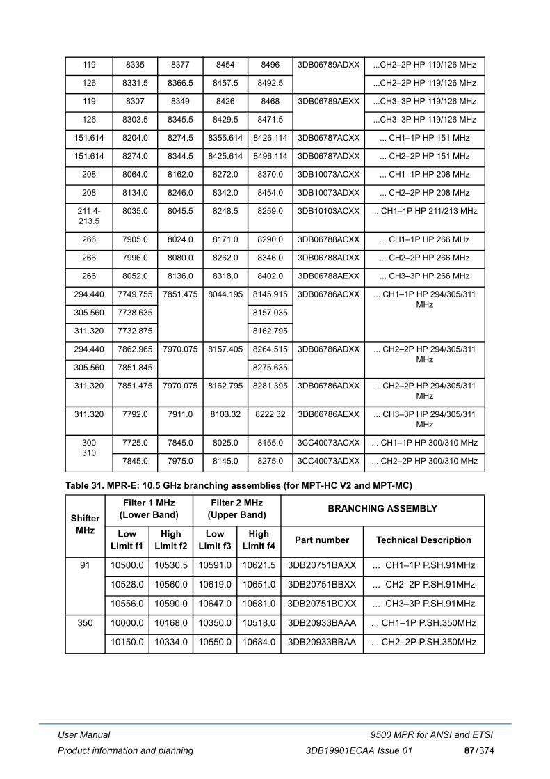
User Manual
Product information and planning
9500 MPR for ANSI and ETSI
3DB19901ECAA Issue 01 87/374
Table 31. MPR-E: 10.5 GHz branching assemblies (for MPT-HC V2 and MPT-MC)
119 8335 8377 8454 8496 3DB06789ADXX ...CH2�2P HP 119/126 MHz
126 8331.5 8366.5 8457.5 8492.5 ...CH2�2P HP 119/126 MHz
119 8307 8349 8426 8468 3DB06789AEXX ...CH3�3P HP 119/126 MHz
126 8303.5 8345.5 8429.5 8471.5 ...CH3�3P HP 119/126 MHz
151.614 8204.0 8274.5 8355.614 8426.114 3DB06787ACXX ... CH1�1P HP 151 MHz
151.614 8274.0 8344.5 8425.614 8496.114 3DB06787ADXX ... CH2�2P HP 151 MHz
208 8064.0 8162.0 8272.0 8370.0 3DB10073ACXX ... CH1�1P HP 208 MHz
208 8134.0 8246.0 8342.0 8454.0 3DB10073ADXX ... CH2�2P HP 208 MHz
211.4-213.5
8035.0 8045.5 8248.5 8259.0 3DB10103ACXX ... CH1�1P HP 211/213 MHz
266 7905.0 8024.0 8171.0 8290.0 3DB06788ACXX ... CH1�1P HP 266 MHz
266 7996.0 8080.0 8262.0 8346.0 3DB06788ADXX ... CH2�2P HP 266 MHz
266 8052.0 8136.0 8318.0 8402.0 3DB06788AEXX ... CH3�3P HP 266 MHz
294.440 7749.755 7851.475 8044.195 8145.915 3DB06786ACXX ... CH1�1P HP 294/305/311 MHz
305.560 7738.635 8157.035
311.320 7732.875 8162.795
294.440 7862.965 7970.075 8157.405 8264.515 3DB06786ADXX ... CH2�2P HP 294/305/311 MHz
305.560 7851.845 8275.635
311.320 7851.475 7970.075 8162.795 8281.395 3DB06786ADXX ... CH2�2P HP 294/305/311 MHz
311.320 7792.0 7911.0 8103.32 8222.32 3DB06786AEXX ... CH3�3P HP 294/305/311 MHz
300310
7725.0 7845.0 8025.0 8155.0 3CC40073ACXX ... CH1�1P HP 300/310 MHz
7845.0 7975.0 8145.0 8275.0 3CC40073ADXX ... CH2�2P HP 300/310 MHz
Shifter MHz
Filter 1 MHz (Lower Band)
Filter 2 MHz(Upper Band) BRANCHING ASSEMBLY
Low Limit f1
High Limit f2
Low Limit f3
High Limit f4 Part number Technical Description
91 10500.0 10530.5 10591.0 10621.5 3DB20751BAXX ... CH1�1P P.SH.91MHz
10528.0 10560.0 10619.0 10651.0 3DB20751BBXX ... CH2�2P P.SH.91MHz
10556.0 10590.0 10647.0 10681.0 3DB20751BCXX ... CH3�3P P.SH.91MHz
350 10000.0 10168.0 10350.0 10518.0 3DB20933BAAA ... CH1�1P P.SH.350MHz
10150.0 10334.0 10550.0 10684.0 3DB20933BBAA ... CH2�2P P.SH.350MHz

User Manual
Product information and planning
9500 MPR for ANSI and ETSI
3DB19901ECAA Issue 0188/374
Table 32. MPT-HC V2/MPT-XP couplers
2.7.7 MPT-HC/MPT-HC V2/MPT-XP optical interface
Table 33 MPT-HC/MPT-HC V2/MPT-XP optical interface
Note: the SFP is mandatory for 1+1 configuration with MPT-HC.
2.8 MPR-A parts lists
2.8.1 Indoor items
Table 34. MPR-A: Indoor items
Description Codes
6 GHz 1 dB/10 dB coupler 3CC58056ABXX
6 GHz 3 dB coupler 3CC58056AAXX
7.1-8.5 GHz 1 dB/10 dB coupler 3CC14536AAXX
7.1-8.5 GHz 3 dB coupler AWY MPT 3CC14536ABAA
10-11.7GHz 3dB coupler 3CC58224AAXX
10.7-11.7 GHz 3 dB coupler 3CC14140AAXX
13-15 GHz 1 dB/10 dB coupler 3CC13472ABXX
13-15 GHz 3 dB coupler AWY MPT 3CC13472AAXX
18-23-25 GHz 1 dB/10 dB coupler 3CC13473ABXX
18-23-25 GHz 3 dB coupler AWY-MPT 3CC13473AAXX
28-32-38 GHz 1 dB/10 dB coupler 3CC13474ABXX
28-32-38 GHz 3 dB coupler AWY MPT 3CC13474AAXX
Description Codes Remarks
SFP 1000Base-Sx Transceiver 1AB383760001/3CC50167AAAA
Optical SFP module to be installed optionally inthe MPT to provide the optical interface
SFP 1000Base-Lx Transceiver 1AB383760002/3CC50168AAAA
Name Part number Remarks
[A] Power Injector box 3CC50129AAXX To be installed in a 19-inch to 21-inch rack toprovide the PFoE to the MPR-e
[B] Power Injector card 3HE07152AAXX To be installed in a 7705 SAR shelf to providethe PFoE to the MPT-HC V2
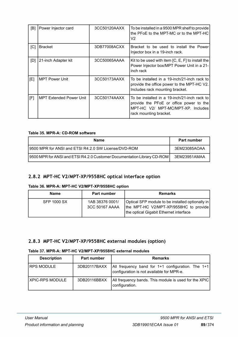
User Manual
Product information and planning
9500 MPR for ANSI and ETSI
3DB19901ECAA Issue 01 89/374
Table 35. MPR-A: CD-ROM software
2.8.2 MPT-HC V2/MPT-XP/9558HC optical interface option
Table 36. MPR-A: MPT-HC V2/MPT-XP/9558HC option
2.8.3 MPT-HC V2/MPT-XP/9558HC external modules (option)
Table 37. MPR-A: MPT-HC V2/MPT-XP/9558HC external modules
[B] Power Injector card 3CC50120AAXX To be installed in a 9500 MPR shelf to providethe PFoE to the MPT-MC or to the MPT-HCV2
[C] Bracket 3DB77008ACXX Bracket to be used to install the PowerInjector box in a 19-inch rack.
[D] 21-inch Adapter kit 3CC50065AAAA Kit to be used with item [C, E, F] to install thePower Injector box/MPT Power Unit in a 21-inch rack
[E] MPT Power Unit 3CC50173AAXX To be installed in a 19-inch/21-inch rack toprovide the office power to the MPT-HC V2.Includes rack mounting bracket.
[F] MPT Extended Power Unit 3CC50174AAXX To be installed in a 19-inch/21-inch rack toprovide the PFoE or office power to theMPT-HC V2/ MPT-MC/MPT-XP. Includesrack mounting bracket.
Name Part number
9500 MPR for ANSI and ETSI R4.2.0 SW License/DVD-ROM 3EM23085AOAA
9500 MPR for ANSI and ETSI R4.2.0 Customer Documentation Library CD-ROM 3EM23951AMAA
Name Part number Remarks
SFP 1000 SX 1AB 38376 0001/3CC 50167 AAAA
Optical SFP module to be installed optionally inthe MPT-HC V2/MPT-XP/9558HC to providethe optical Gigabit Ethernet interface
Description Part number Remarks
RPS MODULE 3DB20117BAXX All frequency band for 1+1 configuration. The 1+1configuration is not available for MPR-e.
XPIC-RPS MODULE 3DB20116BBXX All frequency bands. This module is used for the XPICconfiguration.

User Manual
Product information and planning
9500 MPR for ANSI and ETSI
3DB19901ECAA Issue 0190/374
2.8.4 MPT-HC V2 with internal diplexer
Table 38. MPR-A: MPT-HC V2 with internal diplexer
Band (GHz) Shifter (MHz) Tx sub-band Part number Tx frequency (MHz)
L6 252.04 1 3DB20441BAXX 5930-6050
1P 3DB20443BAXX 6182-6302
2 3DB20442BAXX 6048-6168
2P 3DB20444BAXX 6301-6420
U6 340 1 3DB20437BAXX 6420-6600
1P 3DB20439BAXX 6760-6940
2 3DB20438BAXX 6565-6745
2P 3DB20440BAXX 6905-7085
3 3DB20464BAXX 6595-6775
3P 3DB20465BAXX 6935-7115
11 500-490 1 3DB20371BAXX 10695-10955
1P 3DB20547BAXX 11205-11485
2 3DB20546BAXX 10935-11205
2P 3DB20548BAXX 11445-11705
15 420-475 1 3DB20373BAXX 14500-14724
1P 3DB20423BAXX 14920-15144
18 1560 1 3DB20432BAXX 17700-18140
3DB20432BBXX 17700-18140.5
1P 3DB20433BAXX 19260-19700
3DB20433BBXX 19260-19700.5
23(NB1)
1200-1232 1 3DB20473BAXX 21198-21819
1P 3DB20475BAXX 22400-23019
2 3DB20474BAXX 21781-22400
2P 3DB20476BAXX 22981-23600
38 700 1 3DB20379BAXX 38600-38950
1P 3DB20563BAXX 39300-39650
2 3DB20562BAXX 38950-39300
2P 3DB20564BAXX 39650-40000

User Manual
Product information and planning
9500 MPR for ANSI and ETSI
3DB19901ECAA Issue 01 91/374
2.8.5 MPT-HC V2/MPT-XP/9558HC with external diplexer
The diplexer included in the available BRANCHING assemblies refers to ITU�R F.385, 386.
Each diplexer is a 3-port passive device with two band�pass filters as shown in Figure 30.
Figure 30 MPT-HC V2/MPT-XP/9558HC with external diplexer - diplexer is a 3-port passive device with two band�pass filters
The arrangement between each filter on the same branching device is shown in Figure 31.
Figure 31 MPT-HC V2/MPT-XP/9558HC with external diplexer - arrangement between each filter on the same branching device
WARNING: f1, f2, f3 and f4 frequencies of the branching filters refer to the extreme channel frequenciesand not to the cut-off frequencies of the filters.
2.8.5.1 External Diplexer MPT-HC V2, MPT-XP, 9558HC
Table 39. MPR-A: MPT-HC V2/MPT-XP/9558HC with external diplexer
Band (GHz) Shifter (MHz) Tx sub-band Part number Tx frequency (MHz)
5.8 NA Lower 3DB20913BAXX 5725.5-5785.5
Upper 3DB20914BAXX 5789.5-5849.5
L6 NA Lower 3DB20800BAXX 5930-6168
Upper 3DB20802BAXX 6182-6420

User Manual
Product information and planning
9500 MPR for ANSI and ETSI
3DB19901ECAA Issue 0192/374
Table 40. MPR-A MPT-XP with external diplexer
Table 41. 9558HC 5.8 GHz branching assemblies (for 9558HC)
Table 42. MPR-A L6 GHz branching assemblies (for MPT-HC V2/MPT-XP)
U6 NA Lower 3DB20804BAXX 6420-6775
Upper 3DB20806BAXX 6710-7115
7/8 NA Lower 3DB20454BBXX 7107 - 8370
Upper 3DB20456BBXX 7261 - 8496
Band (GHz) Shifter (MHz) Tx sub-band Part number Tx frequency (MHz)
L6 NA Lower 3DB20760BAXX 5930-6168
Upper 3DB20761BAXX 6182-6420
U6 NA Lower 3DB20763BAXX 6420-6775
Upper 3DB20764BAXX 6710-7115
7 NA Lower 3DB20771BAXX 7107-7714
Upper 3DB20772BAXX 7261-7911
8 NA Lower 3DB20773BAXX 7725-8377
Upper 3DB20774BAXX 8025-8496
Shifter MHz
Filter 1 MHz (Lower Band)
Filter 2 MHz(Upper Band) BRANCHING ASSEMBLY
Low Limit f1
High Limit f2
Low Limit f3
High Limit f4 Part number Technical Description
64 5725.5 5755.5 5789.5 5819.5 3DB20752BAXX CH1-1P P.SH.64MHz
5755.5 5785.5 5819.5 5849.5 3DB20752BBXX CH2-2P P.SH.64MHz
Shifter MHz
Filter 1 MHz (Lower Band)
Filter 2 MHz(Upper Band) BRANCHING ASSEMBLY
Low Limit f1
High Limit f2
Low Limit f3
High Limit f4 Part number Technical Description
252.04 5930.0 6050.0 6182.0 6302.0 3DB20753BAXX ... CH1�1P P.SH.252MHz
6033.0 6168.0 6286.0 6420.0 3DB20753BBXX ... CH2�2P P.SH.252MHz
Band (GHz) Shifter (MHz) Tx sub-band Part number Tx frequency (MHz)

User Manual
Product information and planning
9500 MPR for ANSI and ETSI
3DB19901ECAA Issue 01 93/374
Table 43. MPR-A U6 GHz branching assemblies (for MPT-HC V2/MPT-XP)
Table 44. MPR-A: 7 GHz high power branching assemblies (for MPT-HC V2/MPT-XP)
Table 45. MPR-A: 8 GHz high power branching assemblies (for MPT-HC V2/MPT-XP)
Table 46. MPT-HC/MPT-XP/9558HC couplers
Shifter MHz
Filter 1 MHz (Lower Band)
Filter 2 MHz(Upper Band) BRANCHING ASSEMBLY
Low Limit f1
High Limit f2
Low Limit f3
High Limit f4 Part number Technical Description
160 6540.0 6610.0 6710.0 6780.0 3DB20756BAXX ... CH1�1P P.SH.160MHz
6590.0 6660.0 6750.0 6820.0 3DB20756BBXX ... CH2�2P P.SH.160MHz
6640.0 6710.0 6800.0 6870.0 3DB20756BCXX ... CH3�3P P.SH.160MHz
340 6420.0 6600.0 6760.0 6940.0 3DB20755BAXX ... CH1�1P P.SH.340MHz
6565.0 6720.0 6905.0 7060.0 3DB20755BBXX ... CH2�2P P.SH.340MHz
6595.0 6775.0 6935.0 7115.0 3DB20755BCXX ... CH3�3P P.SH.340MHz
Shifter MHz
Filter 1 MHz (Lower Band)
Filter 2 MHz(Upper Band) BRANCHING ASSEMBLY
Low Limit f1
High Limit f2
Low Limit f3
High Limit f4 Part number Technical Description
150-154 7428.0 7512.0 7582.0 7666.0 3DB06774ACXX ... CH1�1P HP 154_A MHz
150-154 7484.0 7568.0 7638.0 7722.0 3DB06774ADXX ... CH2�2P HP 154_A MHz
175 7125.0 7215.0 7300.0 7390.0 3CC40072ACXX ... CH1�1P HP 175 MHZ
175 7155.0 7250.0 7330.0 7425.0 3CC40072ADXX ... CH2�2P HP 175 MHZ
Shifter MHz
Filter 1 MHz (Lower Band)
Filter 2 MHz(Upper Band) BRANCHING ASSEMBLY
Low Limit f1
High Limit f2
Low Limit f3
High Limit f4 Part number Technical Description
300/310
7725.0 7845.0 8025.0 8155.0 3CC40073ACXX ... CH1�1P HP 300/310 MHz
7845.0 7975.0 8145.0 8275.0 3CC40073ADXX ... CH2�2P HP 300/310 MHz
Description Codes
5.8 GHz unlicenced band unequal loss coupler 3CC58276ABXX
6 GHz 1 dB/10 dB coupler 3CC58056ABXX
6 GHz 3 dB coupler 3CC58056AAXX
7/8 GHz 1 dB/10 dB coupler 3CC14536ABXX

User Manual
Product information and planning
9500 MPR for ANSI and ETSI
3DB19901ECAA Issue 0194/374
2.8.6 MPT-HC/MPT-HC V2/MPT-XP optical interface
Table 47 MPT-HC/MPT-HC V2/MPT-XP optical interface
Note: the SFP is mandatory for 1+1 configuration with MPT-HC.
2.8.7 MPT-HC/MPT-HC V2/MPT-XP optical interface
Table 48 MPT-HC/MPT-HC V2/MPT-XP optical interface
Note: the SFP is mandatory for 1+1 configuration with MPT-HC.
7/8 GHz 3 dB coupler 3CC14536AAAA
11GHz 3dB coupler 3CC14140AAXX
11 GHz 1 dB/10 dB coupler 3CC14140ABXX
13/15 GHz 1 dB/10 dB coupler 3CC13472ABXX
13/15 GHz 3 dB coupler 3CC13472AAXX
18/25 GHz 1 dB/10 dB coupler 3CC13473ABXX
18/25 GHz 3 dB coupler 3CC13473AAXX
28/38 GHz 1 dB/10 dB coupler 3CC13474ABXX
28/38 GHz 3 dB coupler 3CC13474AAXX
Description Codes Remarks
SFP 1000Base-Sx Transceiver 1AB383760001/3CC50167AAAA
Optical SFP module to be installed optionally inthe MPT to provide the optical interface
SFP 1000Base-Lx Transceiver 1AB383760002/3CC50168AAAA
Description Codes Remarks
SFP 1000Base-Sx Transceiver 1AB383760001/3CC50167AAAA
Optical SFP module to be installed optionally inthe MPT to provide the optical interface
SFP 1000Base-Lx Transceiver 1AB383760002/3CC50168AAAA
Description Codes

User Manual
Product information and planning
9500 MPR for ANSI and ETSI
3DB19901ECAA Issue 01 95/374
2.9 Functional description
2.9.1 MPT-HC V2/MPT-XP/9558HC
The MPT-HC V2/MPT-XP/9558HC (Microwave Packet Transport) is Microwave Equipment capable oftransporting Ethernet traffic over an RF radio channel.
The MPT-HC V2/MPT-XP/9558HC includes a waveguide antenna port, one electrical GE interface fordata and power, one SFP port for optical Ethernet data, a maintenance connector (with captive protectioncap) for RSSI access, and a grounding stud.The 1 GE interface for RPS is not used.
The MPT-HC V2/MPT-XP/9558HC can be natively Ethernet powered through a proprietary PFoE.
The MPT-HC V2/MPT-XP/9558HC can host an external module (RPS module for 1+1 configurations orXPIC_RPS module for XPIC and/or 1+1 configurations. The 1+1 configuration is not supported in thecurrent release).
The MPT-HC V2/MPT-XP/9558HC can be rapidly installed on an integrated antenna or on standard poles,wall or pedestal mount, with an appropriate fastening system. The pole mounting is the same from 6 to38 GHz.
The MPT-HC V2/MPT-XP/9558HC (with a solar shield) incorporates the complete RF transceiver and canbe associated with an integrated or separate antenna.
The cabinet is a very compact and robust weatherproof (IP 67) container, designed to be compatible withhot and very sunny climatic zones.
The MPT-HC V2/MPT-XP/9558HC is fixed by means of quick-fastening latches. This system allows theMPT-HC V2/MPT-XP/9558HC to be changed without altering the antenna position.
MPR-E:
For 5.8, 6, 7, 8, and 10.5 GHz (external diplexer), the MPT-HC V2/MPT-XP polarization is determined bythe rotation of the MPT-HC V2/MPT-XP (1+0 configuration).
For 6, and 11 to 38 GHz (embedded diplexer), the MPT-HC V2 polarization is determined by the rotationof the polarization rotator fitted in the antenna port of the MPT-HC V2 (1+0 configuration).
Two mechanical solutions are adopted:
[1] with an embedded diplexer for cost optimisation (6, and 11 to 38 GHz), where the branching(diplexer) is internal to the MPT-HC V2 cabinet; this type of MPT-HC V2 is identified by oneLogistical Item only;
[2] with an external diplexer: due to a high number of shifters, the diplexer is external for the flexibilityof the shifter customization (5.8, 6, 7, 8, and 10.5 GHz), where the MPT-HC V2/MPT-XP iscomposed of two independent units: the BRANCHING assembly (containing the diplexer) and theRF TRANSCEIVER assembly (containing the RF section); each of this type of MPT-HC V2/MPT-XPis identified by two Logistical Items, one for the BRANCHING assembly and another for the RFTRANSCEIVER assembly. To read the BRANCHING assembly identification label, it is necessaryto separate the BRANCHING assembly from the RF TRANSCEIVER assembly.

User Manual
Product information and planning
9500 MPR for ANSI and ETSI
3DB19901ECAA Issue 0196/374
MPR-A:
For 5.8 GHz (external diplexer), the 9558HC polarization is determined by the rotation of the 9558HC (1+0configuration).
For 6, 7, and 8 GHz (external diplexer), the MPT-HC V2/MPT-XP polarization is determined by the rotationof the MPT-HC V2/MPT-XP (1+0 configuration).
For 6, and 11 to 38 GHz (embedded diplexer), the MPT-HC V2 polarization is determined by the rotationof the polarization rotator fitted in the antenna port of the MPT-HC V2 (1+0 configuration).
Two mechanical solutions are adopted:
[1] With an embedded diplexer for cost optimization (6 GHz, and 11 to 38 GHz), shown in 2.9.1.1, wherethe branching (diplexer) is internal to the MPT-HC V2 cabinet; this type of MPT-HC V2 is identifiedby one Logistical Item only.
[2] With an external diplexer: due to a high number of shifters, the diplexer is external for the flexibilityof the shifter customization (5.8, 6, 7, and 8 GHz), where the MPT-HC V2/MPT-XP/9558HC iscomposed of two independent units: the BRANCHING assembly (containing the diplexer) and theRF TRANSCEIVER assembly (containing the RF section); each of this type of MPT-HC V2/MPT-XP/9558HC is identified by two Logistical Items, one for the BRANCHING assembly and another forthe RF TRANSCEIVER assembly. To read the BRANCHING assembly identification label, it isnecessary to separate the BRANCHING assembly from the RF TRANSCEIVER assembly.
The MPT-HC V2/MPT-XP/9558HC consists of the following subcomponents:
� MPT-CB: Common Belt sub-component. This section is frequency-independent, and all the featuresrelevant to this unit are common to all the MPT RF options.
� MPT-RF: Radio Frequency section that is frequency-dependent.
Figure 32 MPT system

User Manual
Product information and planning
9500 MPR for ANSI and ETSI
3DB19901ECAA Issue 01 97/374
The MPT-HC V2/MPT-XP/9558HC interface is based on Gigabit Ethernet, that can be either optical orelectrical depending on the needs and the cable length. If the optical port must be used (data and/or RPSport), the corresponding SFP plug-in must be installed.
Figure 33 MPT-HC V2/MPT-XP/9558HC housing
Figure 34 MPT-HC V2 housing (internal diplexer)
Figure 35 MPT-HC V2/MPT-XP/9558HC housing (external diplexer)

User Manual
Product information and planning
9500 MPR for ANSI and ETSI
3DB19901ECAA Issue 0198/374
2.9.1.1 MPT-HC V2/MPT-XP/9558HC block diagram
Figure 36 MPT-HC V2/MPT-XP/9558HC block diagram
2.9.1.1.1 Common belt section
The Common Belt section is frequency-independent. It is the digital section of the MPT-HC V2/MPT-XP/9558HC.
The main functions are the following:
1) Interfaces the GEthernet Generic Device for traffic transport and MSS communicationmessages in both directions, through one Gigabit Ethernet optical or electrical cable
2) Is a Micro-Processor for
� HW configuration and monitoring of all MPT-HC V2/MPT-XP/9558HC parts� Dynamic regulation process such as ATPC
3) Transports the system reference clock (synchronisation)
4) Extracts management flows from the incoming traffic to the CPU port
5) Performs traffic adaptation if needed
6) Performs Quality of Service and policing on flow to be sent over the radio link
7) Performs modulation and demodulation of the resulting modem frame

User Manual
Product information and planning
9500 MPR for ANSI and ETSI
3DB19901ECAA Issue 01 99/374
Power supply interface
The power supply comes from office power. The MPT-HC V2/MPT-XP/9558HC input voltage range isfrom -28 Vdc to -58 Vdc.
INCA module
The INCA module hosts the physical electrical Ethernet interface.
Tx side
Following the flow from user Ethernet port to radio, the section performs:
� Reception of incoming Ethernet frames from the optical or electrical user interface (through INCA)
� Recovery of the clock coming from the indoor unit
� Switching of the management frames from user port to internal processor
� Generation of MPT-HC V2/MPT-XP/9558HC to MPT-HC V2/MPT-XP/9558HC messages neededfor radio link, such as ATPC or ACM
� Compression of the TDMoEth frames header (TDM2TDM - MEF8, TDM2ETH - MEF8)
� Management of the Quality of Service
� Fragmentation of the Ethernet frames
� Shaping of the traffic to adapt it to radio bandwidth
� Tx Modem frame building
� Tx Radio frame building such as FEC or pilots
� Synchronisation depending on the selected synchronisation mode (SynchE/PCR)
� Modulation in I and Q analog signals to be sent to the RF section
Rx side
Following the flow from radio to user Ethernet port, the section performs:
� Reception of the I and Q analog signals coming from the RF section
� Demodulation of the Rx radio frame into the Rx modem frame
� Deframing of the Rx modem frame
� Re-assembly of the fragmented Ethernet frame
� Decompression of the TDMoEth frames header
� Extraction of MPT-HC V2/MPT-XP/9558HC to MPT-HC V2/MPT-XP/9558HC messages needed forradio link (such as ATPC and ACM)
� Management of service channels frames
� Switching of the management frames from internal processor to user port

User Manual
Product information and planning
9500 MPR for ANSI and ETSI
3DB19901ECAA Issue 01100/374
� Sending of the recovered clock to the indoor unit
2.9.1.1.2 RF section
There are two architectures; the differences between these two architectures are only on the Rx side:
� For the first one (used in MPT-HC V2/MPT-XP band 7/8 GHz), there are only two frequencyconversions between RF input frequency and baseband frequency
� For the second architecture (used for all other MPT-HC V2/MPT-XP/9558HC bands), there are threefrequency conversions
The block diagrams of these two architectures are shown in Figure 37 and Figure 38.
Figure 37 7/8 GHz MPT-HC V2/MPT-XP architecture
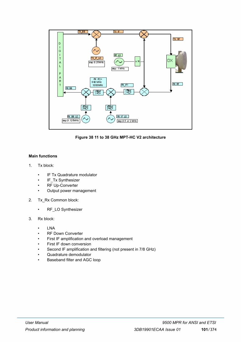
User Manual
Product information and planning
9500 MPR for ANSI and ETSI
3DB19901ECAA Issue 01 101/374
Figure 38 11 to 38 GHz MPT-HC V2 architecture
Main functions
1. Tx block:
� IF Tx Quadrature modulator� IF_Tx Synthesizer� RF Up-Converter� Output power management
2. Tx_Rx Common block:
� RF_LO Synthesizer
3. Rx block:
� LNA� RF Down Converter� First IF amplification and overload management� First IF down conversion� Second IF amplification and filtering (not present in 7/8 GHz)� Quadrature demodulator� Baseband filter and AGC loop

User Manual
Product information and planning
9500 MPR for ANSI and ETSI
3DB19901ECAA Issue 01102/374
2.9.1.2 RSSI monitoring point
The RSSI is available on a connector used to manually point the antenna on the field.
The higher the voltage, the higher the RSSI and the better aligned the antenna is. The RSL is measuredusing a is used a voltmeter connected to the MPR-e with a service kit cable.
Table 49. RSSI table
Note: Without any received signal (Tx mute on the remote MPR-e for example), the RSL valuedisplayed may be more than -100 dBm. This depends on the channelisation/modulationsettings.
2.9.1.3 Waveguide flange data
Table 50. MPR-E waveguide flange data
MPR-A waveguide flange data
Units Measurement (with MPT-HC V2/MPT-XP/9558HC)
Service kit cable(Vdc)
5 4.71 4.12 3.5 2.9 2.3 1.71 1.11 0.59 0.14
RSL (dBm) -10 -20 -30 -40 -50 -60 -70 -80 -90 -100
Wave- guide Type
5.8 GHz
L6 GHz
U6GHz
7 GHz
8 GHz
10.5GHz
11 GHz
13 GHz
15 GHz
18 GHz
23 GHz
25 GHz
38 GHz
WR137 WR137 WR137 WR112
WR112 WR75 WR75 WR62 WR62 WR42 WR42 WR42 WR28
Waveguide Type
5.8 GHz
L6 GHz
U6GHz
7 GHz
8 GHz
11 GHz
15 GHz
18 GHz
23 GHz
38 GHz
WR137 WR137 WR137 WR113 WR113 WR75 WR62 WR42 WR42 WR28

User Manual
Product information and planning
9500 MPR for ANSI and ETSI
3DB19901ECAA Issue 01 103/374
2.9.2 MPT-MC (MPR-E)
MPT-MC is similar to MPT-HC V2 from architecture standpoint.
The only differences are:
� MPT-MC cannot be connected in optical -> 100m length cable limitation.
� MPT-MC does not support the XPIC configuration.
Two mechanical solutions are adopted:
[1] with embedded diplexer for cost optimisation (6 GHz and from 11 GHz to 38 GHz), where thebranching (diplexer) is internal to the MPT-MC cabinet; this type of MPT-MC is identified by oneLogistical Item only;
[2] with external diplexer: due to a vary high number of shifters the diplexer is external for the flexibilityof the shifter customization (L6, U6, 7 GHz and 8 GHz), where MPT-MC is composed by twoindependent units: the BRANCHING assembly (containing the diplexer) and the RF TRANSCEIVERassembly (containing the RF section); each of this type of MPT-MC is identified by two LogisticalItems, one for the BRANCHING assembly and another for the RF TRANSCEIVER assembly. Toread the BRANCHING assembly identification label it is necessary to separate the BRANCHINGassembly from the RF TRANSCEIVER assembly.
Figure 39 MPT-MC housing (internal diplexer)

User Manual
Product information and planning
9500 MPR for ANSI and ETSI
3DB19901ECAA Issue 01104/374
Figure 40 MPT-MC housing (external diplexer)
2.9.3 Power injector
General
The MPT-HC V2/MPT- MC is powered through an electrical Ethernet cable from the Power Injector.
The Power Injector is an indoor device designed to deliver the DC power supply to the MPT-HC V2/MPT-MC by using the cable that carries the Ethernet traffic.
At the input, the Power Injector receives the Ethernet traffic and the power supply on two dedicatedconnectors. The Power Injector outputs, the power supply and Ethernet traffic on one connector. Thissolution, called PFoE (Power Feed over Ethernet), is proprietary.
The Power Injector can power up to 2 MPR-e units.
The two power supply sources provide power supply redundancy.
Main functions of the Power Injector
� Securization of two DC power inputs from -48 VDC office power
� Low pass filtering
� Insertion of the DC voltage on two Ethernet streams to power two MPR-e units
� Surge protection on both Ethernet output ports (K44 & K45)
Power Injector versions
Two versions are available:
1) Power Injector card: installed in the 7705 SAR shelf and powered through the backplane.
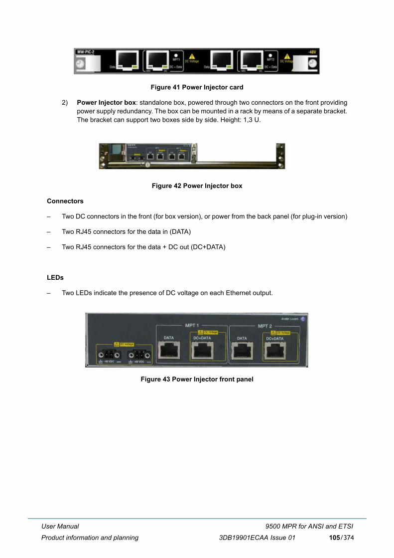
User Manual
Product information and planning
9500 MPR for ANSI and ETSI
3DB19901ECAA Issue 01 105/374
Figure 41 Power Injector card
2) Power Injector box: standalone box, powered through two connectors on the front providingpower supply redundancy. The box can be mounted in a rack by means of a separate bracket.The bracket can support two boxes side by side. Height: 1,3 U.
Figure 42 Power Injector box
Connectors
� Two DC connectors in the front (for box version), or power from the back panel (for plug-in version)
� Two RJ45 connectors for the data in (DATA)
� Two RJ45 connectors for the data + DC out (DC+DATA)
LEDs
� Two LEDs indicate the presence of DC voltage on each Ethernet output.
Figure 43 Power Injector front panel

User Manual
Product information and planning
9500 MPR for ANSI and ETSI
3DB19901ECAA Issue 01106/374
2.9.4 MPT Power Unit
The MPT Power Unit is an indoor device which provides power to up to four MPT using coax cable andType-N connectors.
Figure 44 MPT Power Unit
The MPT Power Unit has 7 connectors:
� Battery A/B (A & B power from office power)
� MPT 1/4 (DC Power to MPT)
� Alarms (Alarm status)
LEDs
� Two LEDs indicate the presence of DC voltage on each power input.
� Four LEDs indicate the presence of DC voltage on each MPT power output.
2.9.5 MPT Extended Power Unit
The MPT Extended Power Unit is an indoor device which provides power to up to two MPT using coaxcable and Type-N connectors. The unit can also provide PFoE using RJ45 connectors.
Figure 45 MPT extended power unit

User Manual
Product information and planning
9500 MPR for ANSI and ETSI
3DB19901ECAA Issue 01 107/374
The MPT Power Unit has 9 connectors:
� Battery A/B (A & B power from office power)
� MPT1/2 IDU Data (Data from MSS-1c)
� MPT1/2 DC + ODU Data (PFoE to MPT)
� MPT1/2 DC (Power Supply to MPT)
� Alarms (Alarm status)
LEDs
� Two LEDs indicate the presence of DC voltage on each power input.
� Two LEDs indicate the presence of DC voltage on each MPT power output.

User Manual
Product information and planning
9500 MPR for ANSI and ETSI
3DB19901ECAA Issue 01108/374
2.9.6 Radio transmission features with MPT-HC V2/MPT-MC/MPT-XP/9558HC
2.9.6.1 Frequency agility
The Frequency Agility feature gives the operator the ability to set the frequency of a single Transceiverwithin a chosen sub-band to select the RF working channel via MCT. This provides benefits for spare parts,order processing and frequency co-ordination.
2.9.6.2 Automatic transmit power control (ATPC)
The Automatic Transmit Power Control (ATPC) function automatically increases or decreases thetransmit output power upon request from the opposite terminal. The opposite terminal constantly monitorsthe Receive Signal Level (RSL), receive signal quality, and aggregate Bit Error Rate (BER) of the receivesignal.
When ATPC is enabled, the transmit output will remain at its lowest level until a fade occurs (or a receivecircuit alarm is detected). When the change in RSL is detected at the receive end, a command is sent tothe transmit end to increase power in 1-dB steps to it's highest level. After the fade is over, the receiveend commands the transmit power to decrease in 1-dB steps to the lowest level.
The ATPC range (high and low limits) is variable, determined by link distance, link location, and linkfrequency. When ATPC Enabled is checked, the range values are shown in parentheses (minimum -maximum) in the ATPC Range field.
When ATPC is disabled the transmit output will always operate at the power value set by the MCT.
2.9.6.3 Transmitted power control: RTPC function
The capability to adjust the transmitted power in a static and fixed way (RTPC = Remote Transmit PowerControl) has been introduced for those countries where, due to internal rules, the ATPC function is notaccepted or for those hops in which due to the short length and interface problems, a fixed reducedtransmitted power is preferred. The range of the possible attenuation depends on the frequency bandinvolved. The setting of the transmitted power can be done locally through MCT.
The Output power is band- and modulation-dependent.
2.9.6.4 Power monitoring
The MPT-HC V2/MPT-XP/9558HC incorporates a detector for Tx power measurement. It is used toprovide measurement of forward power as a performance parameter and to provide a calibration inputfor transmitter operation over temperature and output range.
Viewed Tx power ranges always match the capabilities of the MPT-HC V2/MPT-XP/9558HC for a givenmodulation. When modulation is changed, the CT automatically adjusts/restricts Tx power to be within thevalid range.
2.9.6.5 Adaptive equalization
Adaptive equalization (AE) is employed to improve reliability of operation under dispersive fadeconditions, typically encountered over long and difficult paths.
This is achieved through a multi-tap equalizer consisting of two registers, one with feed-forward taps, theother with feed-back taps. Each of these registers multiply successive delayed samples of the receivedsignal by weighting coefficients to remove propagation-induced inter-symbol interference.

User Manual
Product information and planning
9500 MPR for ANSI and ETSI
3DB19901ECAA Issue 01 109/374
2.9.6.6 1+0 Repeater (with MPT-HC V2, MPT-XP and 9558HC only)
The 1+0 repeater configuration can be setup with two MPR-e placed back-to-back as shown in Figure 46.
Figure 46 1+0 Repeater configuration
This solution is available with MPT-HC V2, MPT-XP, and 9558HC with the following conditions:
� Repeater(s) inserted between two terminal MSS-4/8
� DATA exchange between the two MPR-e through an optical link only
� Synchronization configured in SyncE
� No XPIC configuration
� QoS policy aligned on the 4 stations
� Service: TDM2ETH, Ethernet traffic

User Manual
Product information and planning
9500 MPR for ANSI and ETSI
3DB19901ECAA Issue 01110/374
.
2.9.6.7 XPIC (with MPT-HC V2 and MPT-XP only)
The MPT-HC V2/MPT-XP supports Co-channel Dual Polarized (CCDP) operation using a built-in Cross-polarized Interference Cancellation (XPIC) function. This function is implemented by installing theRPS+XPIC external module. Two links are operated on the same radio channel, with one using the verticalpolarization and the other using the horizontal polarization. XPIC typically provides a 20-dB improvementin polarization discrimination. The actual improvement will depend on the native discrimination providedat antenna alignment and any reduction of this discrimination caused by atmospheric effects (fading).
The XPIC can be implemented with or without the adaptive modulation.
The Radio configuration supported is co-channel XPIC.
Figure 47 Co-channel XPIC
The XPIC configuration is available when MPR-e is standalone and in Single NE mode with 7705 SARconfiguration.
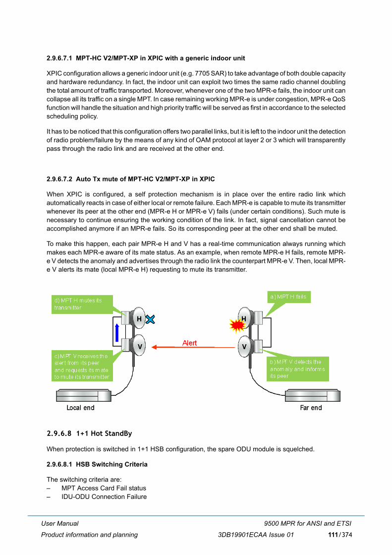
User Manual
Product information and planning
9500 MPR for ANSI and ETSI
3DB19901ECAA Issue 01 111/374
2.9.6.7.1 MPT-HC V2/MPT-XP in XPIC with a generic indoor unit
XPIC configuration allows a generic indoor unit (e.g. 7705 SAR) to take advantage of both double capacityand hardware redundancy. In fact, the indoor unit can exploit two times the same radio channel doublingthe total amount of traffic transported. Moreover, whenever one of the two MPR-e fails, the indoor unit cancollapse all its traffic on a single MPT. In case remaining working MPR-e is under congestion, MPR-e QoSfunction will handle the situation and high priority traffic will be served as first in accordance to the selectedscheduling policy.
It has to be noticed that this configuration offers two parallel links, but it is left to the indoor unit the detectionof radio problem/failure by the means of any kind of OAM protocol at layer 2 or 3 which will transparentlypass through the radio link and are received at the other end.
2.9.6.7.2 Auto Tx mute of MPT-HC V2/MPT-XP in XPIC
When XPIC is configured, a self protection mechanism is in place over the entire radio link whichautomatically reacts in case of either local or remote failure. Each MPR-e is capable to mute its transmitterwhenever its peer at the other end (MPR-e H or MPR-e V) fails (under certain conditions). Such mute isnecessary to continue ensuring the working condition of the link. In fact, signal cancellation cannot beaccomplished anymore if an MPR-e fails. So its corresponding peer at the other end shall be muted.
To make this happen, each pair MPR-e H and V has a real-time communication always running whichmakes each MPR-e aware of its mate status. As an example, when remote MPR-e H fails, remote MPR-e V detects the anomaly and advertises through the radio link the counterpart MPR-e V. Then, local MPR-e V alerts its mate (local MPR-e H) requesting to mute its transmitter.
2.9.6.8 1+1 Hot StandBy
When protection is switched in 1+1 HSB configuration, the spare ODU module is squelched.
2.9.6.8.1 HSB Switching Criteria
The switching criteria are:� MPT Access Card Fail status � IDU-ODU Connection Failure

User Manual
Product information and planning
9500 MPR for ANSI and ETSI
3DB19901ECAA Issue 01112/374
� ICP alarm � Incompatible Shifter alarm � Incompatible Frequency alarm � Incompatible Power alarm � Incompatible Modulation Parameters alarm� Mated MPT Access card Failure� Inter-MPT coupling link failure. Where there is a cross configuration (EPS on Spare & TPS on main),
HSB (TPS) will switch and align with EPS position, if there is an inter-MPT coupling link failure.
2.9.6.9 Link identifier
The number of microwave links, especially in urban areas, might cause interference during installationand the turn-up phase.
The digital frame incorporates link identity coding capabilities to prevent the capture of an unwantedsignal.
If a �Link Identifier Mismatch� occurs all traffic is dropped.
The Link identifier management function can be enabled or disabled by the management system.
2.9.6.10 Loopbacks
To facilitate installation/commissioning and remote maintenance, two loopbacks are available.
As the activation of a loopback affects traffic, the presence of a loopback is indicated to the managementsystems as an abnormal condition.
The supported loopbacks are shown in Figure 48.
Figure 48 Available loopbacks
The following loopbacks are provided by the MPT-HC V2 or MPT-MC or MPT-XP:
1) Line Side loopback: this loopback routes data from the output of the Tx Data Awareness block(after compression) to the input of the Rx data awareness block (decompression). It is a Loop and Continue loopback.When this loopback is activated, the behavior is as follows: � TDM2TDM and TDM2ETH flows are forwarded back to the GEthernet Generic Device
with the source and destination MAC addresses swapped. For TDM2ETH flows, theloopback works only if the ECID Tx and ECID Rx are the same. If the ECID Tx is differentfrom the ECID Rx, the loopback does not work.
� Generic Ethernet flows are dropped.
2) Radio Side loopback: this remote loopback allows an over-the-air loopback test to beperformed when the modem is operating in a continuous mode. The loopback connects the Receive data interface to the Transmit data interface. This loopback is a Loop and Continue loopback.

User Manual
Product information and planning
9500 MPR for ANSI and ETSI
3DB19901ECAA Issue 01 113/374
When this loopback is enabled, the behavior is as follows: � TDM2TDM and TDM2ETH flows are looped back with the source and destination MAC
addresses swapped. For TDM2ETH flows, the loopback works only if the ECID Tx andECID Rx are the same. If the ECID Tx is different from the ECID Rx, the loopback doesnot work.
� Generic Ethernet flows are dropped.
2.9.6.11 Loopback activation
The loopback can be activated by the MCT connected to the NE. The activation command also definesthe duration of the loopback (time-out).
The time-out period starts at the activation time and automatically expires in the NE at the end of theperiod, unless another reconfiguration of the time-out period is requested at the operator interface duringthe activation time. If the loopback is still active because the activation time-out is not expired yet, the time-out period is reconfigurable and the specified time range starts again from the new updated activationdate, overwriting the previous activation date and time-out values.
After the NE reset, the activation of each loopback is disabled and must be recreated again if needed,starting with a new time-out period.
2.9.6.12 Unlicensed radio for 9558HC
The JF6-9558HC/6933B-9558HC (9558HC) unlicensed radio provide fast deployment of service withmicrowave radio. No license and small antennas (no FCC and Industry Canada (IC) requirements) allowimmediate Turn-Up. The 9558HC unlicensed radio can not be upgraded to licensed.
Note: Changes or modifications not expressly approved by Alcatel-Lucent could void the authority tooperate the JF6-9558HC/6933B-9558HC unlicensed radio.
Note: Installation, Turn-Up, Maintenance, and Operation Instruction supplied with the JF6-9558HC/6933B-9558HC unlicensed radio require strict adherence for continued part 15 of the FCCRules and IC RSS-210 compliance.
Table 51. Unlicensed radio
See the Equipping Options Drawing for unlicensed radio configurations and equipping options, found inthe 9500 MPR-A Engineering Support Documentation manual (PN 3EM23957AM).
The 9558HC unlicensed radio operate in the 5725-5850 Information, Scientific, and Medical (ISM) bandin accordance with FCC Part 15.247 and IC RSS-210. This unlicensed radio, although operating in thesame band as a spread spectrum radio, operates using narrower bandwidths than spread spectrum.Advantages, disadvantages, and antenna recommendations for the unlicensed radio follow:
Advantages:
� Fast installation and Turn-Up
� Between 6.6 � 185 Mb/s user configurable data payload capacity consisting of a combination ofDS1, DS3, and/or Ethernet traffic
� Field expandable to higher capacities.
Transceiver FCC ID Industry Canada ID
9558HC JF6-9558HC 6933B-9558HC

User Manual
Product information and planning
9500 MPR for ANSI and ETSI
3DB19901ECAA Issue 01114/374
� Common network management with licensed radios.
� Common spares and training with licensed radios
� Adaptive Modulation - automatic interference countermeasures
Disadvantages:
� Interference from other 5725-5850 ISM band transmissions are possible
� Operating restrictions
� 5.725 to 5.850 GHz band
� Performance could deteriorate due to interference as the frequency band becomes congested.
Antenna recommendations:
� Frequency � 5.8 GHz
� Size and Type � 2, 4, 6, 8, or 10 foot parabolic; 1 or 2 foot flat panel.� Parabolic antennas, See Table 52..� Flat antennas, See Table 52..
� Gain and 3 dB Beamwidth
This device has been designed to operate with the antennas listed below, and having a maximum gainof 42.5 dB. Antennas not included in this list or having a gain greater than 42.5 dB are strictly prohibitedfor use with this device. The required antenna impedance is 50 ohms.
These antennas can only be used in a fixed point-to-point configuration.
To reduce potential radio interference to other users, the antenna type and its gain should be so chosenthat the equivalent isotropically radiated power (e.i.r.p) is not more than that permitted for successfulcommunication.
The antenna(s) used for this transmitter must be installed to provide a separation distance of at least 12meters from all persons and must not be co-located or operating in conjunction with any other antennaor transmitter.
DANGER: Danger of public exposure to long term RF radiated energy. When using a 1 ft flat panelantenna with a 1 watt (+30 dBm) output power, the antenna must be located in an area that doesnot allow the general population access to within 12 meters (5.8 Ghz) of the antenna.
Table 52. 5.8 GHz unlicensed antenna optionsPARABOLIC FLAT
9558HC 9558HC2 ft parabolic � 29 dB/6° 1 ft flat panel � 23 dB/9°4 ft parabolic � 35 dB/3° 2 ft flat panel � 28 dB/3.5°6 ft parabolic � 38 dB/2° �

User Manual
Product information and planning
9500 MPR for ANSI and ETSI
3DB19901ECAA Issue 01 115/374
Frequency Plan: For 9558HC frequency plan for the 5.725 and 5.850 GHz unlicensed band, refer toFigure 49.
Output Power: A requirement of operating in the unlicensed band is to limit transmit output power to notmore than +30.0 dBm at the antenna port. It is the responsibility of the user to transmit not more than +30.0dBm.
Note: To meet FCC part 15 requirements, output power for MPT-HC 30 MHz 4QAM and 8QAMchannels must not be provisioned greater than 24 dBm. This is not enforced by the userinterface and is the responsibility of the operator to guarantee provisioning of the radio transmitpower. For transmit power specification, refer to the System Application Rules document, foundin the 9500 MPR-A Engineering Support Documentation manual (PN 3EM23957AM).
Figure 49 Frequency plan 9558HC: 5.725 to 5.850 GHz unlicensed band(FCC Part 15 and IC RSS-210)

User Manual
Product information and planning
9500 MPR for ANSI and ETSI
3DB19901ECAA Issue 01116/374
2.9.7 MPR-e standalone IP addresses
2.9.7.1 NE IP addresses
The NE IP address is a network IP address used to access the MPR-e through the radio and trafficEthernet traffic port.
This address is configured statically by the operator through the management system.
The default IPv4 address is 10.0.1.2.
The subnet mask is 255.255.255.255 (/32). This mask is fixed and not configurable by the operator.
2.9.7.2 TMN-RF
The TMN-RF interface is associated with the radio port and is used to connect the MPR-e to the NE onthe other side of the radio link. There are two different selectable modes for this interface: PPP or In-Band.
When an MPR-e is interfacing with any NE belonging to the MPR family at the other end of a radio link,TMN-RF PPP is required. TMN-RF PPP doesn�t have an explicit IP address configuration because itautomatically inherits the NE IP address.
When the NE at the other end is a 7705 SAR in Single NE with MPR-e, TMN-RF In-Band is required. AsTMN In-Band, this interface requires a unique IP address, a subnet mask and a unique VLAN ID (it cannotbe the same as the TMN In-Band VLAN ID). The 7705 SAR must have a similar valid interface within thesame subnet with the same VLAN ID as the MPR-e to establish IP connectivity over the radio link.
2.9.7.3 TMN In-Band
The TMN In-Band interface dedicated to TMN is used to connect the MPR-e NE to the LAN exchangingTMN information through a VLAN mixed with the user Ethernet traffic.
This interface has a local default IP address, and the operator can reconfigure this IP address as a publicaddress.
The IP address of the TMN In-Band interface can be equal to the local IP address (NE IP address).
If the IP address is different from the NE IP address, the TMN In-Band subnet is different from the NElogical subnet calculated by masking the NE IP address with the TMN In-Band subnet mask.
The default address is 192.168.100.1.
The default subnet mask is 255.255.255.0 (/24).
The default TMN In-Band VLAN ID is 4080.
2.9.8 SAR and MPR-e Single NE IP addresses
When MPR-e is used in Single NE mode with 7705 SAR, MPR-e does not have its own IP address.Conversely, all MPR-e to 7705 SARs are reachable with any SAR IP addresses (IPv4 only).
MPR-e management traffic is handled by SAR routing function like any other IP stream. As a directconsequence, there is no longer a special channel carrying TMN that the MPR-e can explicitly recognizeby use of a VLAN ID. Management traffic back and forth from the MPR-e follows the 7705 SAR QoS policyand profile.

User Manual
Product information and planning
9500 MPR for ANSI and ETSI
3DB19901ECAA Issue 01 117/374
2.9.9 Quality of service (QoS)
The QoS functions must be properly configured in order to achieve the required behavior on Ethernetflows that will be transmitted.
Figure 50 shows an overview of the QoS implementation inside the MPT.
Figure 50 QoS in the MPT
The QoS feature provides eight internal queues to support different traffic priorities. The QoS functionassigns the packet to one of the eight egress transmit queues.
� Queue 8 is assigned to TDM2TDM traffic (not used in the current release)
� Queue 7 is assigned to TDM2Eth traffic
� Queue 6 is assigned to TMN
Queues 1 to 5 are assigned to Ethernet traffic according to the information inside the packet as 802.1pfield, DiffServ field or Ethertype.
All the MEF-8 ETH2ETH traffic flows are assigned to the Q5 egress priority queue.
QoS based on IEEE std. 802.1p
When the 802.1p QoS mechanism is adopted, the reference is the standard �IEEE 802.1D-2004 AnnexG User priorities and traffic classes�, which defines eight traffic types and the corresponding user priorityvalues.
In the Radio Interface module for generic Ethernet traffic, there are five egress queues; therefore, themapping of the 802.1p value to a queue is as shown in Table 53.
Table 53. QoS based on 802.1p priority802.1p priority Queue
111, 110 Q5 (higher priority)
101 Q4
100 Q3
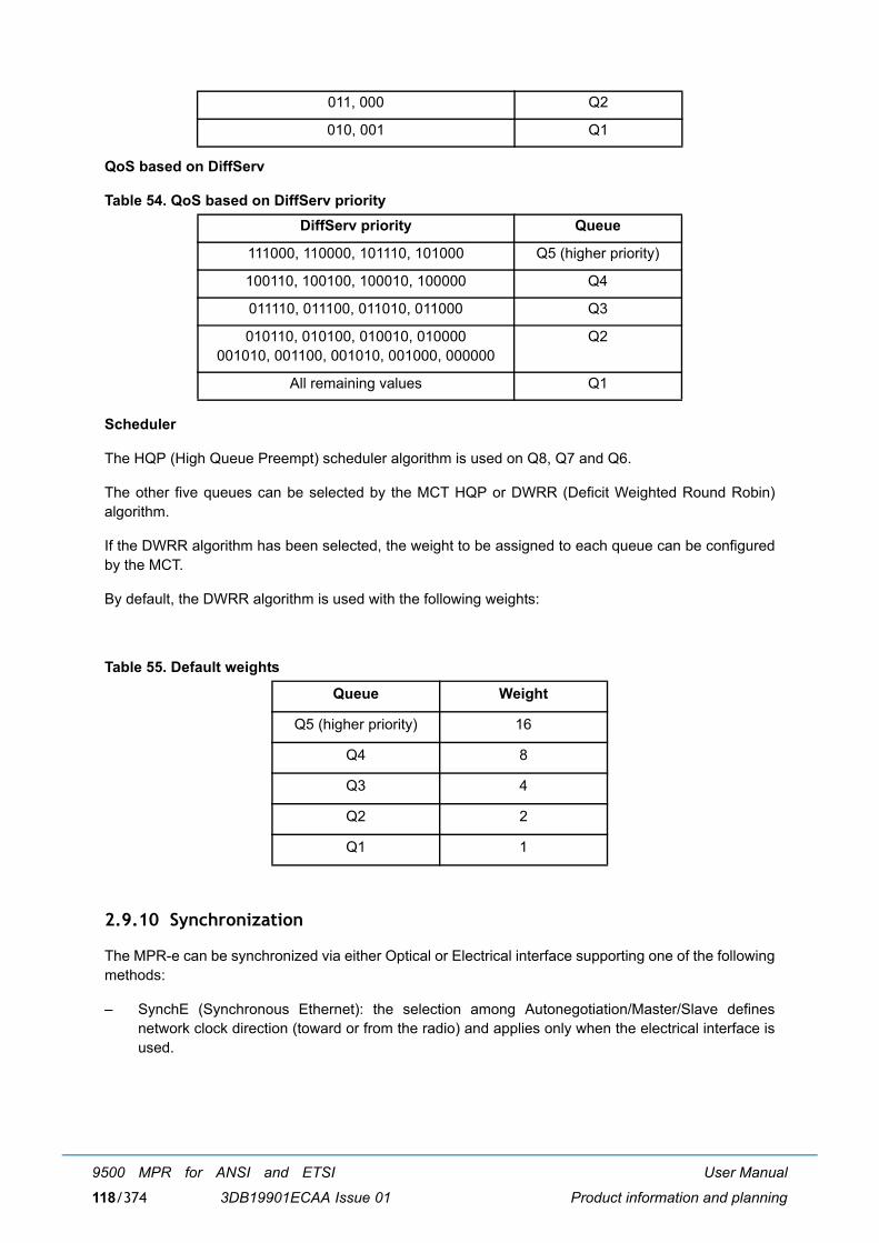
User Manual
Product information and planning
9500 MPR for ANSI and ETSI
3DB19901ECAA Issue 01118/374
QoS based on DiffServ
Table 54. QoS based on DiffServ priority
Scheduler
The HQP (High Queue Preempt) scheduler algorithm is used on Q8, Q7 and Q6.
The other five queues can be selected by the MCT HQP or DWRR (Deficit Weighted Round Robin)algorithm.
If the DWRR algorithm has been selected, the weight to be assigned to each queue can be configuredby the MCT.
By default, the DWRR algorithm is used with the following weights:
Table 55. Default weights
2.9.10 Synchronization
The MPR-e can be synchronized via either Optical or Electrical interface supporting one of the followingmethods:
� SynchE (Synchronous Ethernet): the selection among Autonegotiation/Master/Slave definesnetwork clock direction (toward or from the radio) and applies only when the electrical interface isused.
011, 000 Q2
010, 001 Q1
DiffServ priority Queue
111000, 110000, 101110, 101000 Q5 (higher priority)
100110, 100100, 100010, 100000 Q4
011110, 011100, 011010, 011000 Q3
010110, 010100, 010010, 010000001010, 001100, 001010, 001000, 000000
Q2
All remaining values Q1
Queue Weight
Q5 (higher priority) 16
Q4 8
Q3 4
Q2 2
Q1 1

User Manual
Product information and planning
9500 MPR for ANSI and ETSI
3DB19901ECAA Issue 01 119/374
� PCR (Proprietary Clock Recovery): PCR is a copper synchronous Ethernet-based, timing-over-packet technology. In standalone mode, the Source MAC address and the Destination MAC addressmust be assigned. In Single NE mode with 7705 SAR, PCR provides frequency synchronizationbetween an MPR-e radio and an MWA port on a 7705 SAR-8 or 7705 SAR-18 (a PMC is required).
� The MPR-e can also use its internal reference and discard any external synchronization.
Note: SSM is transparently forwarded in most of the configurations (See the Release Notice forexceptions).
2.9.10.1 Synchronization: MPR-e standalone and 7705 SAR
In case of optical interface between MPR-e standalone and 7705 SAR, standard SynchE shall be used.On the contrary, when copper interface is selected, synchronization must be provisioned for PCR betweenthe MPR-e and a microwave port on the 7705 SAR.
On the 7705 SAR side, PCR is always turned on automatically when a microwave link is enabled on anMWA RJ-45 port or copper SFP is used.
On the MPR-e side, the MPR-e that is connected to the 7705 SAR-8 or 7705 SAR-18 must have PCRenabled and the source and destination MAC addresses of the 7705 SAR-8 or 7705 SAR-18 must beconfigured as shown in Table 56.
Table 56. 7705 SAR PMC card MAC addresses
SAR slot # PMC port # Source MAC address Destination MAC address
1 1 00-80-9F-09-F1-11 00-80-9F-09-F1-01
2 00-80-9F-09-F1-21
3 00-80-9F-09-F1-31
4 00-80-9F-09-F1-41
2 1 00-80-9F-09-F2-12 00-80-9F-09-F2-02
2 00-80-9F-09-F2-22
3 00-80-9F-09-F2-32
4 00-80-9F-09-F2-42
3 1 00-80-9F-09-F3-13 00-80-9F-09-F3-03
2 00-80-9F-09-F3-23
3 00-80-9F-09-F3-33
4 00-80-9F-09-F3-43
4 1 00-80-9F-09-F4-14 00-80-9F-09-F4-04
2 00-80-9F-09-F4-24
3 00-80-9F-09-F4-34
4 00-80-9F-09-F4-44

User Manual
Product information and planning
9500 MPR for ANSI and ETSI
3DB19901ECAA Issue 01120/374
5 1 00-80-9F-09-F5-15 00-80-9F-09-F5-05
2 00-80-9F-09-F5-25
3 00-80-9F-09-F5-35
4 00-80-9F-09-F5-45
6 1 00-80-9F-09-F6-16 00-80-9F-09-F6-06
2 00-80-9F-09-F6-26
3 00-80-9F-09-F6-36
4 00-80-9F-09-F6-46
71 1 00-80-9F-09-F7-17 00-80-9F-09-F7-07
2 00-80-9F-09-F7-27
3 00-80-9F-09-F7-37
4 00-80-9F-09-F7-47
81. 1 00-80-9F-09-F8-18 00-80-9F-09-F8-08
2 00-80-9F-09-F8-28
3 00-80-9F-09-F8-38
4 00-80-9F-09-F8-48
91. 1 00-80-9F-09-F9-19 00-80-9F-09-F9-09
2 00-80-9F-09-F9-29
3 00-80-9F-09-F9-39
4 00-80-9F-09-F9-49
101. 1 00-80-9F-09-FA-1A 00-80-9F-09-FA-0A
2 00-80-9F-09-FA-2A
3 00-80-9F-09-FA-3A
4 00-80-9F-09-FA-4A
111. 1 00-80-9F-09-FB-1B 00-80-9F-09-FB-0B
2 00-80-9F-09-FB-2B
3 00-80-9F-09-FB-3B
4 00-80-9F-09-FB-4B
121. 1 00-80-9F-09-FC-1C 00-80-9F-09-FC-0C
2 00-80-9F-09-FC-2C
3 00-80-9F-09-FC-3C
4 00-80-9F-09-FC-4C
SAR slot # PMC port # Source MAC address Destination MAC address

User Manual
Product information and planning
9500 MPR for ANSI and ETSI
3DB19901ECAA Issue 01 121/374
The source and destination MAC addresses can also be summarized by the following formula linked tothe slot and port number in HEX:
PMC card source MAC address: 00-80-9F-09-F<slot#>-<port#><slot#>
PMC card destination MAC address: 00-80-9F-09-F<slot#>-0<slot#>
For example, for slot number 4 and port number 2:
Source MAC address = 00-80-9F-09-F4-24
Destination MAC address = 00-80-9F-09-F4-04
2.9.10.2 Synchronization: 7705 SAR and MPR-e Single NE
In a Single NE solution no special configuration is required. Both 7705 SAR and MPR-e self-detect theport selected and consequently configure the correct synchronization method.
When copper interface is used either using native RJ-45 or Copper SFP on the PMC (7705 SAR) side,PCR is selected both by MPR-e and 7705 SAR self-assigning right MAC addresses.
When optical interface is used, SynchE is selected by both MPR-e and 7705 SAR.
1. Slot 7 TO 12 are applicable to SAR-18 chassis only.

User Manual
Product information and planning
9500 MPR for ANSI and ETSI
3DB19901ECAA Issue 01122/374

User Manual
NE management by software application
9500 MPR for ANSI and ETSI
3DB19901ECAA Issue 01 123/374
3 NE management by software application
3.1 Security session management
The MCT will close automatically after 30 minutes of session inactivity.
This is not applicable in the following cases:
� When the 15 minutes or 24 hours Performance Monitoring is activated (Normalized, Adaptive or QoSEthernet)
� When the monitoring of the Power measurements or Modem measurements is activated
� When the NE is configured in Single NE mode with 7705 SAR
After 25 minutes of idle session, a message dialog will be displayed on the MCT to inform the user aboutthe expiration of the session.The user has 5 minutes to decide to continue or to stop his session.
Figure 51 Session expiration message
Press the �Stay Connected � button to keep the current session active. The idle period is then restarted.
Press the �Disconnect� button to close the current MCT session.
If no action is done, the MCT will close automatically after the remaining time displayed on the messagedialog.
Figure 52 Connection lost message

User Manual
NE management by software application
9500 MPR for ANSI and ETSI
3DB19901ECAA Issue 01124/374
3.2 WebEML start
This chapter explains all the screens of the WebEML (JUSM/CT), which is started by a double click onthe WebEML icon on the PC desktop.
The WebEML must be connected to the GEthernet Generic Device as explained in Chapter 5.
Refer to paragraph 4.4 - �Software local copy� for information on copying the WebEML from the softwarepackage CD ROM/DVD ROM and connecting the PC to the GEthernet Generic Device in order to accessthe MPT-HC V2/MPT-MC/MPT-XP/9558HC.
Note: The PC should be in the same sub-network as the default IP address of the TMN in-band (firstconnection); see Chapter 6 for configuration information. If TMN in band is different from theLocal NE IP, there also needs to be a route on the PC with the gateway of the TMN in band.
1) To start the WebEML, double click on the relevant icon on the PC desktop. The NEtO windowappears.
2) NEtO opens. Insert the IP address of the NE (default: 10.0.1.2) and click OK.
3) A banner appears. If you agree to the Acknowledgement of Authorization, click on the Acceptbutton.
Figure 53 Consent banner
4) When the NE is supervised (LED appears green), click on the Show button. The Main viewappears.

User Manual
NE management by software application
9500 MPR for ANSI and ETSI
3DB19901ECAA Issue 01 125/374
Figure 54 NEtO main view
Figure 55 Main view: system overview
Note: If the WebEML is connected to an MPT-HC V2/MPT-XP/9558HC with the XPIC + RPS externalmodule installed (but with no XPIC feature configured), the screen in Figure 56 will appear.

User Manual
NE management by software application
9500 MPR for ANSI and ETSI
3DB19901ECAA Issue 01126/374
Figure 56 Main view: System overview with MPT-HC V2/MPT-XP with XPIC module
3.3 7705 SAR and MPR-e in Single NE: MCT Launcher start
In 9500 MPR R4.1.0, the MCT Launcher is the application that interfaces with the 7705 SAR to show themicrowave configuration of the system. This application is the entry point for accessing each individualMPR-e connected to a 7705 SAR in Single NE mode. For any supported radio configuration, each MPR-e is accessed individually and its configuration is performed separately in a dedicated MCT session.
This chapter describes all the screens of the MCT Launcher. The MCT Launcher must be connected tothe 7705 SAR as explained in Chapter 5.
Refer to paragraph 4.4 - �Software local copy� for information on copying the MCT Launcher from thesoftware package CD ROM/DVD ROM and connecting the PC to the console port on the 7705 SAR inorder to access the MPR-e.
Note: The PC must be in the same subnet as the 7705 SAR IP interface (first connection); seeChapter 6 for configuration information.
[1] To start the MCT Launcher, double-click on the MctLauncher icon on the PC desktop. The MCTLauncher window opens.
Figure 57 MCT Launcher icon

User Manual
NE management by software application
9500 MPR for ANSI and ETSI
3DB19901ECAA Issue 01 127/374
[2] Enter the IP address of the 7705 SAR along with the 7705 SAR username and password (defaultis admin admin for both username and password) and click on the Finish button.
Figure 58 MCT Launcher startup screen
[3] The MCT Launcher main screen opens, showing site information and a list of radios configured.
Figure 59 MCT Launcher main screen
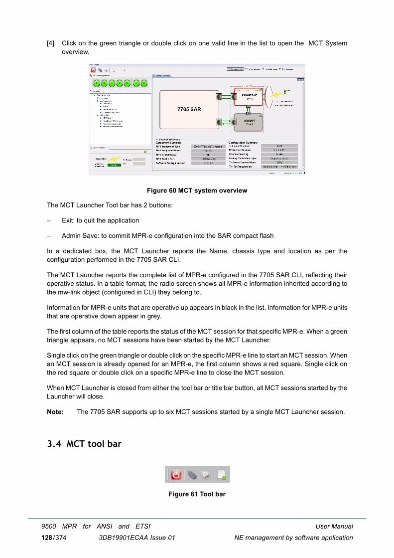
User Manual
NE management by software application
9500 MPR for ANSI and ETSI
3DB19901ECAA Issue 01128/374
[4] Click on the green triangle or double click on one valid line in the list to open the MCT Systemoverview.
Figure 60 MCT system overview
The MCT Launcher Tool bar has 2 buttons:
� Exit: to quit the application
� Admin Save: to commit MPR-e configuration into the SAR compact flash
In a dedicated box, the MCT Launcher reports the Name, chassis type and location as per theconfiguration performed in the 7705 SAR CLI.
The MCT Launcher reports the complete list of MPR-e configured in the 7705 SAR CLI, reflecting theiroperative status. In a table format, the radio screen shows all MPR-e information inherited according tothe mw-link object (configured in CLI) they belong to.
Information for MPR-e units that are operative up appears in black in the list. Information for MPR-e unitsthat are operative down appear in grey.
The first column of the table reports the status of the MCT session for that specific MPR-e. When a greentriangle appears, no MCT sessions have been started by the MCT Launcher.
Single click on the green triangle or double click on the specific MPR-e line to start an MCT session. Whenan MCT session is already opened for an MPR-e, the first column shows a red square. Single click onthe red square or double click on a specific MPR-e line to close the MCT session.
When MCT Launcher is closed from either the tool bar or title bar button, all MCT sessions started by theLauncher will close.
Note: The 7705 SAR supports up to six MCT sessions started by a single MCT Launcher session.
3.4 MCT tool bar
Figure 61 Tool bar

User Manual
NE management by software application
9500 MPR for ANSI and ETSI
3DB19901ECAA Issue 01 129/374
The MCT tool bar has 4 buttons:
� Exit: to quit the application
� Connect to NE: to establish the connection to the NE
� Disconnect: to disconnect from the NE
� Export NE Information: to export the NE configuration and current alarms to a text file. Only theinformation related to the MPR-e is reported.
3.5 Alarm synthesis
The CT provides an alarm functionality that informs the operator on the severity of the different alarmsin the NE as well as on the number of current alarms. There are five different alarm severity levels. In theCT these different levels are associated with colors.
� Red: Critical alarm (CRI)
� Orange: Major alarm (MAJ)
� Yellow: Minor alarm (MIN)
� Cyan: Warning alarm (WAR)
� Blue: Indeterminate (IND)
The meaning of each icon in the Alarm Synthesis is:
[1] CRI - Critical alarmSynthesis of alarms relevant to the reach ability of the NE (typical: NE isolation)
[2] MAJ - Major (Urgent) alarmSynthesis of alarms that need immediate troubleshooting
[3] MIN - Minor (Not Urgent) alarmSynthesis of alarms for which an intervention can be deferred
[4] WAR - Warning alarmSynthesis of alarms due to failure of another NE in the network
[5] IND - Indeterminate alarmSynthesis of alarms not associated with the previous severities. Not operative.
Each alarm severity is represented by an alarm icon situated in the top left hand corner of the view. Thesealarm icons are always represented on the different Equipment views so that the operator is always awareof the alarms occurring in the system.
Furthermore the number in the alarm icon indicates the number of active alarms with that specific severity.
3.6 Domain alarm synthesis area
This area contains the icons representing the alarms per domain. Each icon indicates the number of alarmoccurrences for each domain.

User Manual
NE management by software application
9500 MPR for ANSI and ETSI
3DB19901ECAA Issue 01130/374
The meaning of each icon in the Domain alarm synthesis area is:
[1] COM � Communication alarmSynthesis of alarms in the Communication domain
[2] EQP � Equipment alarmSynthesis of alarms in the Equipment domain
3.7 General information on the management state
The different management states concerning the NE are shown in two tab-panels:
� Radio Synthesis
� Radio Synthesis with XPIC configured (only with MPT-HC V2/MPT-XP/9558HC)
� Network Supervision
The Radio Synthesis provides information about the:
� Abnormal Condition state: indicates whether abnormal conditions have been recognized.
The Network Supervision gives information on the:
� Local Access state: indicates whether the NE is managed by a craft terminal or by the OS
User Manual
NE management by software application
9500 MPR for ANSI and ETSI
3DB19901ECAA Issue 01 131/374
� OS Supervision state: indicates whether the communication with the OS is established
3.8 Navigator area
The Navigator menu depends on the selected function in the upper tab-panels.
Four tab-panels are available:
[1] Commissioning (par. 3.8.1)
� Inventory
� Software download for MPR-e standalone
� Configuration (par. 3.8.1.3)
� Date/time � Site information � Radio scheme configuration � 1+1 HSB configuration� Radio� Advanced Radio� Ethernet traffic QoS� TDM cross-connections� Networking
� Backup / restore
� Monitoring
[2] Performance monitoring (par. 3.8.2)
� Performance history file upload
� Normalized
� Adaptive modulation
� Qos ethernet
� Traffic port ethernet
� Monitoring
[3] Troubleshooting (par. 3.8.3)
� Inventory
� Troubleshooting
� Monitoring
[4] Maintenance (par. 3.8.4)
� Inventory
� Software download for MPR-e standalone

User Manual
NE management by software application
9500 MPR for ANSI and ETSI
3DB19901ECAA Issue 01132/374
� Configuration > Radio
� Monitoring
The System Overview tab-panel (Figure 55 and Figure 60) is a read-only screen, which shows all theconfiguration parameters of the MPT.
3.8.1 Commissioning
This menu has five sub-menus:
� Inventory
� Software download for MPR-e standalone
� Configuration
� Backup / restore
� Monitoring
Note: Not all menus are applicable in Single NE mode with 7705 SAR configuration.
3.8.1.1 Inventory
This menu displays all the inventory data of the MPT.
Figure 62 Inventory

User Manual
NE management by software application
9500 MPR for ANSI and ETSI
3DB19901ECAA Issue 01 133/374
3.8.1.2 Software download for MPR-e standalone
This menu must be used to download a new software version on the NE (Software Package Versionstab-panel) or to get a summary of the specific software versions on the programmable differentcomponents on the Active bank (Active Software Package Summary tab-panel) or on the Stand-by bank(Stand-by Software Package Summary tab-panel).
3.8.1.2.1 Software package versions tab-panel
Figure 63 Software download: Software package versions
Warning: On the PC containing the Software Package must be installed an FTP Server.
The PC's firewall (i.e Microsoft's default firewall) may prevent the download from starting up.
[1] The Apache Server, installed with the WebEML from the TCO Software Suite R4.10 DVD-ROM, isstarted with NEtO as the default FTP server. Check that the following parameters have been correctlysetup.� Server Address: PC address� Username: anonymous� Password: anonymous� Port: 21
[2] Click on the Check button.
[3] In the Software Package field, select the file descriptor (previously copied to the PC).
When the Apache FTP server (embedded in the TCO SW Suite) is used, it is mandatory to copy theSWP component to the FTP root directory:�\Document and Settings\<login name>\9500MPR-E\res\home�. For example, �R95MPRE/4_1_0� must to be copied to:�\Document and Settings\<login name>\9500MPR-E\res\home�. See Figure 253.
Note: The path to the file descriptor, after the SWP local copy, is //ECT/SWDW/R95MPRE/

User Manual
NE management by software application
9500 MPR for ANSI and ETSI
3DB19901ECAA Issue 01134/374
Figure 64 Directory for the SW component if Apache FTP server is in use
[4] Put a check mark on the Forced check box to download the complete file without any comparisonbetween the file already present in the stand-by bank and the new file to be downloaded.
[5] Click on the Start Download button.
[6] At the end press the Activate button of the Stand-by Software Package.
Note: After the activation of the Standby bank, the connection between the WebEML and MPR-e islost. The WebEML must be relaunched.
Figure 65 Software download

User Manual
NE management by software application
9500 MPR for ANSI and ETSI
3DB19901ECAA Issue 01 135/374
3.8.1.2.2 Active software package summary tab-panel
This tab-panel shows the versions of the programmable different components of the active bank.
Figure 66 Software download: Active software package summary
3.8.1.2.3 Stand-by software package summary tab-panel
This tab-panel shows the versions of the programmable different components of the stand-by bank.
Figure 67 Software download: Stand-by software package summary

User Manual
NE management by software application
9500 MPR for ANSI and ETSI
3DB19901ECAA Issue 01136/374
3.8.1.3 Configuration
3.8.1.3.1 Date/time
The NE Date/Time screen displays the current NE time and the current computer time.
To re-align the NE time with the computer time, click on the Synchronize NE with Computer button andclick on the Refresh button.
If an SNTP Server must be used to distribute the time, the SNTP protocol must be enabled by a checkmark in the SNTP Enabled box and the IP address of the Server must be entered in the relevant field.The IP address of the Spare Server, if available, must be entered in the relevant field.
Figure 68 Date/time configuration
This menu is not applicable in Single NE mode with 7705 SAR configuration.
3.8.1.3.2 Site information
This menu has to be used to enter the optional information to identify the site (Site Name and SiteLocation).

User Manual
NE management by software application
9500 MPR for ANSI and ETSI
3DB19901ECAA Issue 01 137/374
Figure 69 Site information
This menu is not applicable in Single NE mode with 7705 SAR configuration.
3.8.1.3.3 Radio scheme configuration
For MPR-e standalone, the protection scheme must be explicitly selected as 1+0. When the MPR-e is inSingle NE mode with 7705 SAR, the protection scheme is ruled by the 7705 SAR according to mw-linkconfiguration in the CLI.
3.8.1.3.3.1 1+0 configuration
Figure 70 1+0 Protection configuration

User Manual
NE management by software application
9500 MPR for ANSI and ETSI
3DB19901ECAA Issue 01138/374
3.8.1.3.3.2 1+1 HSB configuration in Single NE mode with 7705 SAR
In 9500 MPR Release 4.1.0, when 1+1 HSB is selected, the screen reports the status of the EPS, TPSand RPS protection. This screen reports only the current status and configuration: it cannot be used tomake configuration changes. For more detailed information on 1+1 HSB protection and relative operatorcommands, see the 7705 SAR OS 6.0.R1 documentation.
Caution: There is no automatic synchronization of the configuration of the two MPTs in a 1+1 HSBconfiguration. The MCT sessions for the main and the spare MPTs are separate: the operator must verifythat the configurations are aligned.
Note: 1+1 HSB is only supported by 9500 MPR Release 4.1.0 when the MPR-e is in Single NE modewith 7705 SAR; see paragraph 2.1.4 for more detailed information.
Figure 71 1+1 HSB configuration
3.8.1.3.4 Synchronization
This menu allows the operator to synchronize the MPR-e. As described in section 2.9.10.2, when MPR-e is in Single NE mode with 7705 SAR, synchronization is self detected and configured. Consequently,this menu is not available in Single NE mode with 7705 SAR.
Note: .
Two ways for external synchronization or internal synchronization mode can be selected.
� External synchronization:
� PCR (Figure 72)� SyncE (Figure 73)
� Internal synchronization (Figure 74)

User Manual
NE management by software application
9500 MPR for ANSI and ETSI
3DB19901ECAA Issue 01 139/374
Figure 72 Synchronization (PCR)
Figure 73 Synchronization (SyncE)

User Manual
NE management by software application
9500 MPR for ANSI and ETSI
3DB19901ECAA Issue 01140/374
Figure 74 Synchronization (Internal)
� If PCR has been selected, the Source Mac Address and the Destination MAC Address have tobe entered.
Note: Synchronization must be provisioned for PCR between the MPR-e standalone and a PMC porton the 7705 SAR. The source and destination MAC addresses for the 7705 SAR are availablein Table 56.
� If SyncE has been selected, for the electrical interface, select Automatic, Master, or Slave.
Note: The SyncE Synchronization screen shows the result of the autonegotiation process. This resultis displayed with a �LED� icon.
� Autonegotiation in progress: the LED is flashing� Autonegotiation completed in Master or Slave mode: the LED is green
� in automatic mode

User Manual
NE management by software application
9500 MPR for ANSI and ETSI
3DB19901ECAA Issue 01 141/374
Figure 75 Automatic mode
� in manual mode
Figure 76 Manual mode
� Autonegotiation failed, and the mode is declared as "Not negotiated": the LED is red.

User Manual
NE management by software application
9500 MPR for ANSI and ETSI
3DB19901ECAA Issue 01142/374
Figure 77 Autonegotiation failed
� The LED is gray when the link down alarm is raised out of context of an autonegotiation.
Figure 78 Link down alarm
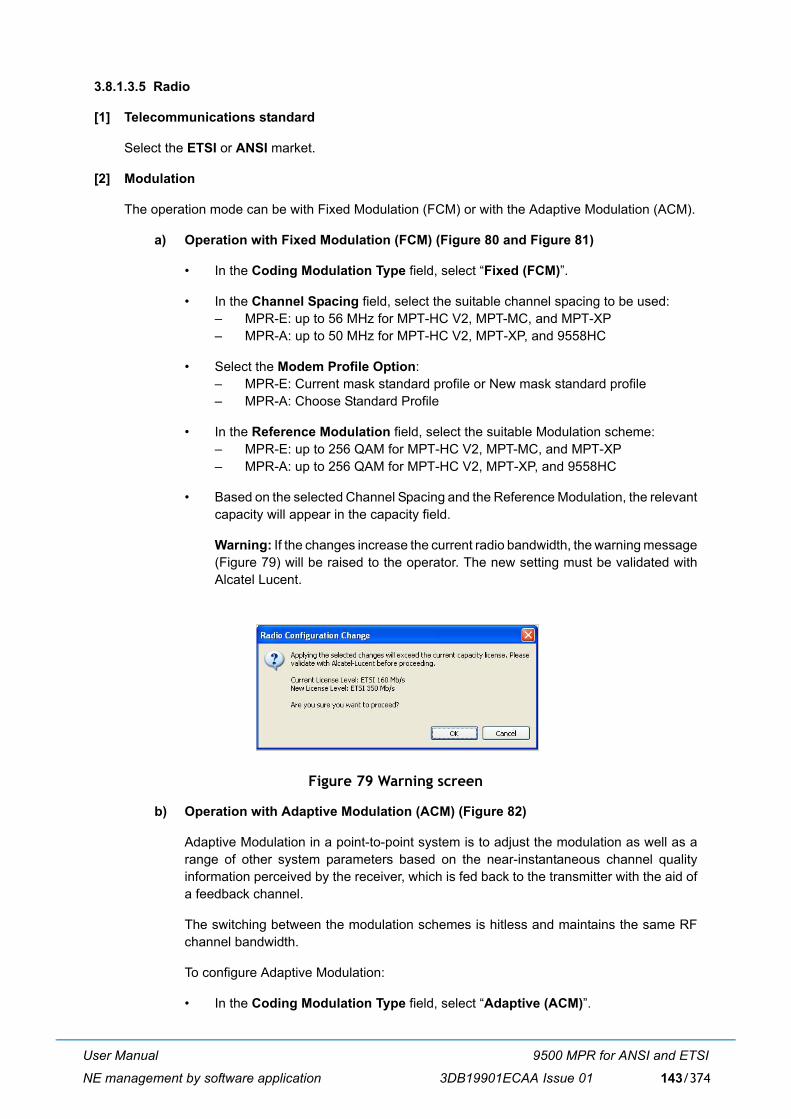
User Manual
NE management by software application
9500 MPR for ANSI and ETSI
3DB19901ECAA Issue 01 143/374
3.8.1.3.5 Radio
[1] Telecommunications standard
Select the ETSI or ANSI market.
[2] Modulation
The operation mode can be with Fixed Modulation (FCM) or with the Adaptive Modulation (ACM).
a) Operation with Fixed Modulation (FCM) (Figure 80 and Figure 81)
� In the Coding Modulation Type field, select �Fixed (FCM)�.
� In the Channel Spacing field, select the suitable channel spacing to be used:� MPR-E: up to 56 MHz for MPT-HC V2, MPT-MC, and MPT-XP� MPR-A: up to 50 MHz for MPT-HC V2, MPT-XP, and 9558HC
� Select the Modem Profile Option: � MPR-E: Current mask standard profile or New mask standard profile� MPR-A: Choose Standard Profile
� In the Reference Modulation field, select the suitable Modulation scheme:� MPR-E: up to 256 QAM for MPT-HC V2, MPT-MC, and MPT-XP� MPR-A: up to 256 QAM for MPT-HC V2, MPT-XP, and 9558HC
� Based on the selected Channel Spacing and the Reference Modulation, the relevantcapacity will appear in the capacity field.
Warning: If the changes increase the current radio bandwidth, the warning message(Figure 79) will be raised to the operator. The new setting must be validated withAlcatel Lucent.
Figure 79 Warning screen
b) Operation with Adaptive Modulation (ACM) (Figure 82)
Adaptive Modulation in a point-to-point system is to adjust the modulation as well as arange of other system parameters based on the near-instantaneous channel qualityinformation perceived by the receiver, which is fed back to the transmitter with the aid ofa feedback channel.
The switching between the modulation schemes is hitless and maintains the same RFchannel bandwidth.
To configure Adaptive Modulation:
� In the Coding Modulation Type field, select �Adaptive (ACM)�.

User Manual
NE management by software application
9500 MPR for ANSI and ETSI
3DB19901ECAA Issue 01144/374
� In the Channel Spacing field, select the suitable channel spacing.
� Select the Modem Profile Option: � MPR-E: Current mask standard profile or New mask standard profile� MPR-A: Choose Standard Profile
� In the Reference Modulation field, select the reference modulation, whichcorresponds to the lowest modulation scheme.
� In the Allowed Modulation field, select all the modulation schemes to be used withthe Adaptive Modulation. The modulation schemes (from the lowest to the highestscheme) must be contiguous.
Warning: If the changes increase the current radio bandwidth, the warning message(Figure 79) will be raised to the operator. The new setting must be validated withAlcatel Lucent.
[3] Frequency
The system can operate with different types of ODUs according to the RF band and to the channelarrangement. There are ODUs that can manage only one shifter or several predefined shifters.
In the Shifter field, select the suitable shifter.
In the Tx frequency field, enter the suitable Tx frequency (the Rx frequency is automaticallycalculated by using the entered Tx frequency and the shifter).
The Rx frequency field will displays the calculated Rx frequency, but, by selecting the Allow RxFrequency Tuning check box this frequency can be changed in +5 MHz increments to implementthe �Exotic� shifter configuration, if required.
[4] Tx Mute
To mute the transmitter, select the Mute check box.
Note: In a 1+1HSB configuration in Single NE mode with 7705 SAR, in order to mute the entiremw-link a "TX-Mute" command shall be applied to both Main and Spare radios.
[5] Transmit Power Control Mode
Select the Mode: RTPC or ATPC.
[6] RTPC settings
� Tx power without Adaptive Modulation
If the ATPC is disabled, the Tx Power field is available. The Tx Power range is displayed in thescreen.
In this field, enter the new value within the allowed transmitted power range.
� Tx Power with Adaptive Modulation
You can modify only the Tx power relevant to the lowest modulation scheme. In this field youmust enter the constant power, which will be used with the lowest modulation.
Note: The same power value will be used by the other modulation schemes.
[7] ATPC settings

User Manual
NE management by software application
9500 MPR for ANSI and ETSI
3DB19901ECAA Issue 01 145/374
The ATPC cannot be set with ACM (only with FCM).
� ATPC Remote RSL Threshold
The value of the low power threshold can be changed by writing the new value in the field. Whenthe Rx power is equal to this power the ATPC algorithm starts to operate.
� Min ATPC Tx power and Max ATPC Tx power
The Min Tx power and Max Tx power, within the Tx Range in the ATPC management, canbe written in the relevant field.
Figure 80 Radio configuration: FCM - RTPC

User Manual
NE management by software application
9500 MPR for ANSI and ETSI
3DB19901ECAA Issue 01146/374
Figure 81 Radio configuration: FCM - ATPC

User Manual
NE management by software application
9500 MPR for ANSI and ETSI
3DB19901ECAA Issue 01 147/374
Figure 82 Radio configuration: ACM - RTPC
[8] XPIC (only with MPT-HC V2/MPT-XP)
The XPIC can be configured only for an MPT-HC V2/MPT-XP with the �RPS + XPIC� externalmodule. XPIC is not available in 1+1 HSB protection.
The XPIC can be configured with or without Adaptive Modulation.
� In the Modem Profile Option field select a profile with the XPIC.
� In the XPIC Polarization field select the polarization to be associated with the MPT-HC V2/MPT-XP: Horizontal or Vertical.
� Configure the second MPT-HC V2/MPT-XP to be associated in the XPIC configuration with thesame profile and with opposite polarization.

User Manual
NE management by software application
9500 MPR for ANSI and ETSI
3DB19901ECAA Issue 01148/374
Figure 83 XPIC configuration
When the XPIC has been configured, the MPT-HC V2/MPT-XP with the XPIC module and with theassociated polarization will appear in the System Overview screen (refer to Figure 84).
Figure 84 XPIC with horizontal polarization system overview

User Manual
NE management by software application
9500 MPR for ANSI and ETSI
3DB19901ECAA Issue 01 149/374
When the XPIC has been configured in the Radio Synthesis tab-panel the XPD value is shown (seeFigure 85).
Figure 85 XPD
Warning: When you change a radio parameter (such as modulation mode ACM/FCM, modulation/capacity, Tx or Rx freq or shifter value), a warning message is raised (refer to Figure 86). You needto ensure that the radio configuration between the two MPTs involved in XPIC is aligned.
Figure 86 Warning message
3.8.1.3.6 Advanced Radio
Figure 87 Advanced radio configuration

User Manual
NE management by software application
9500 MPR for ANSI and ETSI
3DB19901ECAA Issue 01150/374
This menu is used to specify the expected and sent identifier values of parameters related to the linkmanagement and, if necessary, to modify them.
If the link identifier is Enabled, the following fields can be filled in:
� Tx Radio Link Identifier: this field is the link identifier entered on the transmitting NE (1 to 255)
� Expected Rx Radio Link Identifier: this field is the link identifier expected at the receiving NE (0to 255).
Note: If the Expected Rx Link Identifier is "0", there is no link identifier mismatch management.
� Packet Throughput Booster: In order to improve the use on air bandwidth, the MPT can compress the packet applying thefollowing principle: whenever a packet is received with a known packet header at remote site,the MPT saves bandwidth by not transmitting this header each time. Only some learning bytesallow to index the corresponding known packet header.
When activated the MPT will compress, when possible, the packet to save air bandwidth. Toactivate the Packet Throughput Booster tick the relevant check box in this field.
Note: The remote NE must have also enabled its " Packet Throughput Booster " feature fordecompression capabilities.
3.8.1.3.7 Ethernet traffic QoS
This menu allows to:
[1] Select the QoS Classification
[2] Set the Classification according to the EtherType
[3] Set the Scheduling Algorithms
Note: For the QoS the first match for the classification is done according to 802.1p/DiffServ (point [1]).If there is no match, the classification is done according to the EtherType (point [2]). If there isno match, the Ethernet frame is sent to the lower-priority queue.

User Manual
NE management by software application
9500 MPR for ANSI and ETSI
3DB19901ECAA Issue 01 151/374
Figure 88 Ethernet traffic QoS
[1] QoS classification
Two methods can be selected:
� IEEE 802.1p (refer to Figure 89)
� DiffServ (refer to Figure 90)
IEEE 802.1p
Figure 89 IEEE 802.1p

User Manual
NE management by software application
9500 MPR for ANSI and ETSI
3DB19901ECAA Issue 01152/374
Select the appropriate check boxes for each priority (0 to 7) to be assigned to a specific egress queue(queue 1 to 5).
Note: Queue 5 is the highest-priority queue; queue 1 is the lowest-priority queue.
You can click on the Default button to restore the default classification.
DiffServ
Figure 90 DiffServ
A specific range of DiffServ Code Points can be assigned to a specific egress queue (queue 1 toqueue 5).
Note: Queue 5 is the highest-priority queue, queue 1 is the lowest-priority queue.
You can click on the Default button to restore the default classifications.
Click on the Add button to add a range that can be assigned to a specific queue.
[2] EtherType classification
Click on the Add (or Add Last) button to assign a specific egress queue (queue 1 to queue 5) toa specific EtherType.
Note: Queue 5 is the highest-priority queue; queue 1 is the lowest-priority queue.

User Manual
NE management by software application
9500 MPR for ANSI and ETSI
3DB19901ECAA Issue 01 153/374
Figure 91 EtherType classification
[3] Scheduling algorithms
Figure 92 Scheduling algorithms
This menu allows to change the scheduler operation.
Note: The scheduling mode refers only to queue 1 to 5, because for queue 6 to 8 the schedulingmode is fixed to HQP.
The scheduling mode can be DWRR or HQP.

User Manual
NE management by software application
9500 MPR for ANSI and ETSI
3DB19901ECAA Issue 01154/374
If DWRR has been selected the DWRR weight can be assigned to a specific egress queue (queue1 to queue 5).
Note: Queue 5 is the highest-priority queue; queue 1 is the lowest-priority queue (valid only forHQP).
Click on the Defaults button to restore the default algorithm.
Note: the HQP mode can be associated with some queues and DWRR mode can be associatedwith other queues. DWRR cannot be assigned to higher-priority queues than thoseconfigured for HQP.
3.8.1.3.8 TDM cross-connections
This menu allows you to create TDM2ETH cross-connections.
Figure 93 Cross-connection creation
To manage the cross-connections, select one of the following buttons:
� Add new cross-connection
� Clone cross-connection
� Modify selected cross-connection
� Remove cross-connection
To create the TDM2ETH cross-connection:
1) Click the Add new cross-connection button2) Enter the VLAN ID3) Enter the MAC address of the destination IWF4) Enter the clock source: Differential or Adaptive
Buttons to
manage the
cross-
connections

User Manual
NE management by software application
9500 MPR for ANSI and ETSI
3DB19901ECAA Issue 01 155/374
5) Click on the Add button
The created cross-connection will appear in the cross-connection list, as shown in Figure 94.
Figure 94 Cross-connection list
An existing cross-connection can be:
� modified by pressing the Modify cross-connection button (Figure 95)
� deleted by pressing the Remove cross-connection button
� cloned by pressing Clone cross-connection button to create another cross-connection bymodifying the parameters and then pressing the Add clone button (Figure 96)

User Manual
NE management by software application
9500 MPR for ANSI and ETSI
3DB19901ECAA Issue 01156/374
Figure 95 Cross-connection modify
Figure 96 Cross-connection clone

User Manual
NE management by software application
9500 MPR for ANSI and ETSI
3DB19901ECAA Issue 01 157/374
This menu is not applicable in Single NE mode with 7705 SAR configuration. In Single NE mode with 7705SAR, cross-connections are set up as part of configuration of the 7705 SAR.
3.8.1.3.9 Networking
This menu must be used to assign (or to show) the networking configuration of the NE.
This menu has three sub-menus:
� Network Interfaces
� Static Routing
� Routing Table
� Trusted SNMP Managers
None of the networking screens are available when MPR-e is in Single NE mode with 7705 SARconfiguration. The MPR-e is integrated into the SAR and has to be considered one of its peripherals.
3.8.1.3.9.1 Network interfaces
Figure 97 Network interfaces
� TMN RF field
Select a check box to obtain access to the NE in the remote radio station.
TMN RF can be set up over PPP protocol or through an In-Band management (to inter-operate withNEs that do not support PPP).

User Manual
NE management by software application
9500 MPR for ANSI and ETSI
3DB19901ECAA Issue 01158/374
1) For the TMN RF over PPP, tick the �TMN RF PPP� (as shown in Figure 97)
2) For the In-band management, tick the �TMN RF In-Band�. Then configure the IP address, thenetwork mask and the VLAN ID [range 2..4080] allocated to the TMN RF in-band interface. ThisIP address and the remote NE TMN RF In-band IP address must be in the same subnet.
Figure 98 TMN RF field
Note: The TMN RF in-band Van ID must be different from the one configured for User Ethernet TMNin-band.
Note: You need to ensure the consistency of the TMN RF configuration at both ends of the radiointerface, otherwise the TMN RF in-band link will not set up.
� NE IP Parameters field
This IP address is the local IP address. The default IP address is: 10.0.1.2. The subnet mask is255.255.255.255(/32) and cannot be changed.
� TMN In-band IP parameters
Enter the IP Address with the relevant subnet mask for TMN In-band management. Default IP addresses: 192.168.100.1. Default subnet mask: 255.255.255.0(/24).In the VLAN ID field enter the VLAN ID used for In-band management (default: 4080).
Note: Changes to these parameters will cause the connection with the MPR-e to be dropped.
Note: Depending on the changes to the parameters and the type of generic device, it may benecessary to change the parameters of the PC/device.
� OSPF Management fieldThis field includes two areas (Areas and Interfaces) to manage OSPF.
Each OSPF interface is attached to an OSPF Area the OSPF Area Id. For example, in Figure 97, TMNRF is in OSPF Area: 0.0.0.0.
� How to add an OSPF Area
Figure 99 Areas
Click here to add anew OSPF Area

User Manual
NE management by software application
9500 MPR for ANSI and ETSI
3DB19901ECAA Issue 01 159/374
1) Configure the Area Identifier and Area Type fields, then click on the Add button. Aconfiguration message will appear.
Figure 100 OSPF Areas Management
2) Click on the OK button.
Figure 101 Configuration message
Note: When the 9500 MPR is used with other equipment, the OSPF interface parameters of theequipment must be the same as those of the related TMN interface on the 9500 MPR.
The 9500 MPR OSPF parameters are:
� Hello Interval: 10 seconds
� Router Dead Interval: 40 seconds
� Retransmit Interval: 5 seconds
� Interface Transit Delay: 1 second
� MTU: 1500 bytes
� How to remove an OSPF Area
Figure 102 Areas
Configure the Area Type, then click on the Modify button. A configuration message will appear. Clickon the OK button.
Click here to remove theselected OSPF Area

User Manual
NE management by software application
9500 MPR for ANSI and ETSI
3DB19901ECAA Issue 01160/374
Figure 103 Configuration message
� How to modify an OSPF Area
Figure 104 Areas
Change the Area Type, then push the Modify button.
Figure 105 Modify OSPF Area
� How to attach an interface to an OSPF Area
Figure 106 Interfaces
Select an OSPF Area in which the interface has to be added, then click on the Attach button.
Click here to modify theselected OSPF Area
Click here to attach theselected interface to anOSPF Area

User Manual
NE management by software application
9500 MPR for ANSI and ETSI
3DB19901ECAA Issue 01 161/374
Figure 107 Network interfaces attachment to an OSPF Area
� How to detach an interface
Figure 108 Interfaces
Select None, then push the Detach button.
Figure 109 Network interfaces attachment to an OSPF Area
3.8.1.3.9.2 Static routing
The Static Routing menu is used to configure the parameters for IP Static Routing Configuration.
� Route Type: the options are Network, Host, and Default.
� Destination an address or a range of IP addresses with the subnet mask.
� Next Hop: the User can select Point to Point Link to address the link on the radio side or GatewayIP to define the address of a gateway reachable on the TMN In-band interface.
Click here to detach theselected interface fromits OSPF Area

User Manual
NE management by software application
9500 MPR for ANSI and ETSI
3DB19901ECAA Issue 01162/374
Figure 110 Static routing
The Add button inserts a new Static Routing Table row above the selected row.
The Add Last inserts a new Static Routing Table row below the last row.
The Delete button deletes the selected Static Routing Table row.
Note: For each change, click the Apply button to execute the request.
3.8.1.3.9.3 Routing Table
This menu is a read-only window with the IP routing information summary.
Figure 111 Routing Table

User Manual
NE management by software application
9500 MPR for ANSI and ETSI
3DB19901ECAA Issue 01 163/374
Note: Click on the Refresh button to display the latest changes.
3.8.1.3.9.4 Trusted SNMP Managers
A Trusted manager is an SNMP manager to which the NE automatically sends the traps generated insidethe NE.
Figure 112 Trusted SNMP Managers
To activate a Trusted Manager, enter the IP Address of the SNMP manager, the Traps UDP Port andthe Manager Type (Network Manager Layer or Equipment Manager Layer), then click on the Registerbutton.
Note about the Manager Type: � �Network Manager Layer� must be used for 5620 SAM and other NMS system.� �Equipment Manager Layer� must be used for 1350 OMS system type (where the "alarm type" field
is removed from the alarm traps) when automatic registration of the manager is not possible
Note: The "Traps UDP port" corresponds to the port on which the Manager receives the traps.
In Figure 113, one Manager has been created.
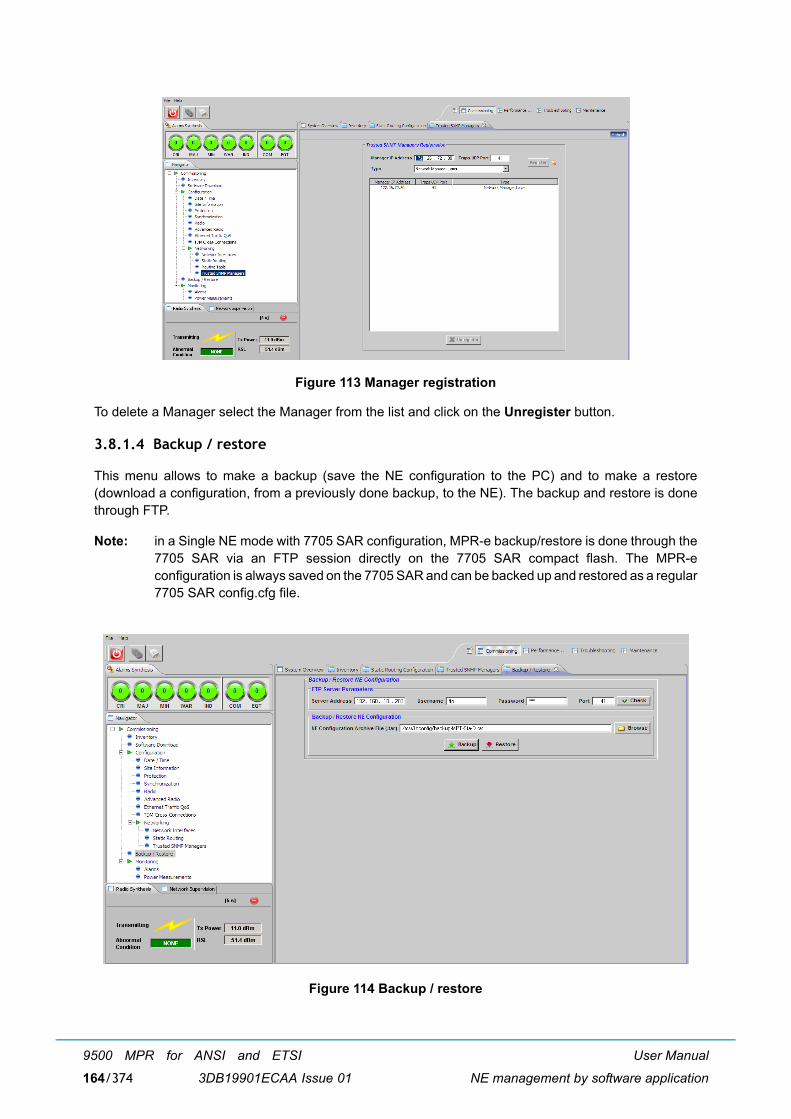
User Manual
NE management by software application
9500 MPR for ANSI and ETSI
3DB19901ECAA Issue 01164/374
Figure 113 Manager registration
To delete a Manager select the Manager from the list and click on the Unregister button.
3.8.1.4 Backup / restore
This menu allows to make a backup (save the NE configuration to the PC) and to make a restore(download a configuration, from a previously done backup, to the NE). The backup and restore is donethrough FTP.
Note: in a Single NE mode with 7705 SAR configuration, MPR-e backup/restore is done through the7705 SAR via an FTP session directly on the 7705 SAR compact flash. The MPR-econfiguration is always saved on the 7705 SAR and can be backed up and restored as a regular7705 SAR config.cfg file.
Figure 114 Backup / restore

User Manual
NE management by software application
9500 MPR for ANSI and ETSI
3DB19901ECAA Issue 01 165/374
Fill the FTP Server Parameters fields.
Click on the Browse button to select the directory and the name of the file.
Click on the Backup or Restore button as required.
3.8.1.5 Monitoring
For this menu, see paragraph 3.8.5.
3.8.2 Performance monitoring
This menu has the following sub-menus:
� Performance history file upload
� Normalized
� Adaptive modulation
� Qos ethernet
� Traffic port ethernet
� Monitoring
3.8.2.1 Performance history file upload
This menu allows to export a .csv file with data regarding the performance counters. This operation is donethrough an FTP session. This menu is not available in Single NE mode with 7705 SAR.
[1] the Apache Server, available on the TCO Software Suite R4.10 DVD-ROM, is used as default FTPserver. Check that the following parameters have been correctly setup.� Server address: PC address� Username: anonymous� Password: anonymous� Port: 21

User Manual
NE management by software application
9500 MPR for ANSI and ETSI
3DB19901ECAA Issue 01166/374
[2] In the Performance Family field, select the type of counters to be exported: NormalizedPerformance Counters (see par. 3.8.2.2) / Adaptive Modulation Counters (see par. 3.8.2.3) / MPR-e QoS Ingress Counters (see par. 3.8.2.4.1) / Traffic Port Counters (see par. 3.8.2.5.1).
Note: The counters to be exported must be stopped (refer to the relevant paragraphs).
Note: The counters use GMT timestamps.
[3] Select the History Period (in seconds - default: 5 s for the QoS Ethernet and Traffic Port EthernetCounters; 15 m or 24 h for the Normalized and Adaptive counters) and click on the Apply button.
[4] Click on the Browse button to choose the destination directory and to assign the name of the file.
[5] Click on Upload History to export the file.
Figure 115 Performance history file upload
For the Qos Ethernet Counter history and Traffic Port Ethernet Counters the counter period duration canbe adjusted from 5 to 3600s. It can be modified by typing the in the History Period field and applying thevalue.

User Manual
NE management by software application
9500 MPR for ANSI and ETSI
3DB19901ECAA Issue 01 167/374
Figure 116 Qos ethernet counter period duration
3.8.2.2 Normalized
The MPR-e supports normalized Hop PM for both 1+0 and 1+1 HSB configuration in Single NE mode with7705 SAR.
When in 1+1 HSB configuration, Link PM is also provided by the EPS active MPR-e. The EPS standbyMPR-e reports only Hop PM and no data for Link PM. Whenever an EPS switch occurs (automatic orissued by operator), the current period is declared suspected and PM link monitoring continues on thenew EPS active MPR-e.
3.8.2.2.1 Counters thresholds
In the Counters Thresholds screen the Low Threshold and High Threshold can be changed for eachG.826 parameter (BBE, ES, SES). The high threshold will cause the activation of the alarm "Thresholdexceeded" during the Performance Monitoring period and the low threshold will cause the deactivationof the same alarm.
Note: For the 24-hour report only the High Threshold can be changed.
Click on the Apply button to send the new parameters to the equipment.
Click on the Default button to restore the default parameters.

User Manual
NE management by software application
9500 MPR for ANSI and ETSI
3DB19901ECAA Issue 01168/374
Figure 117 Counters thresholds
3.8.2.2.2 15Min counters
The upper part of the screen will show the values of the current 15-min period; the lower part will showthe last elapsed 15-min period.
Click on the Activate button (1) to activate the 15-min normalized NE counter computation.
Click on the Start icon (2) to start the monitoring of the current 15-min period (if the NE countercomputation is activated) and set the refresh period (range from 1s to 60s with default value to 5s).
Click on the Reset button to reset the NE counter computation (if the NE counter computation is activated).

User Manual
NE management by software application
9500 MPR for ANSI and ETSI
3DB19901ECAA Issue 01 169/374
Figure 118 15Min counter activation
Figure 119 15Min counter
When a 15-min period is over, the period data is automatically reported and shown on the lower part ofthe window.

User Manual
NE management by software application
9500 MPR for ANSI and ETSI
3DB19901ECAA Issue 01170/374
Figure 120 15Min counter history
Click on the Stop icon (1) to stop the current 15-min counter monitoring.
Click on the Deactivate button to deactivate the 15-min normalized NE counter computation (if thecounter monitoring is stopped).
Figure 121 15Min counter deactivation

User Manual
NE management by software application
9500 MPR for ANSI and ETSI
3DB19901ECAA Issue 01 171/374
3.8.2.2.3 24H counters
The 24H Counters menu is identical to the 15Min Counters menu, but the period is 24 hours rather than15 minutes.
3.8.2.2.4 Import history
This menu displays the counters of the history report.
� Select Import History and click on the Load button.
Figure 122 Import history
� Select the file to be opened and click on the Open button.
Figure 123 File selection
Load

User Manual
NE management by software application
9500 MPR for ANSI and ETSI
3DB19901ECAA Issue 01172/374
The history file opens showing the performance report.
3.8.2.3 Adaptive modulation
The Adaptive Modulation Counter screen will show the total seconds during which each modulationscheme has been used.
3.8.2.3.1 15Min counters
The upper part of the screen will show the values of the current 15-min period; the lower part will showthe last elapsed 15-min period.
Click on the Activate button (1) to activate the 15-min normalized NE counter computation.
Click on the Start icon (2) to start the monitoring of the current 15min period (if the NE counter computationis activated) and set the refresh period (range from 1s to 60s with default value to 5s).
Press the Reset button to reset the NE counter computation (if the NE counter computation is activated).
Figure 124 Adaptive modulation counter activation

User Manual
NE management by software application
9500 MPR for ANSI and ETSI
3DB19901ECAA Issue 01 173/374
Figure 125 15Min counter
When a 15-min period is over, the period data is automatically reported and shown in the lower part ofthe window.
Figure 126 15Min counters history
Click on the Stop icon (1) to stop the current 15-min counters monitoring.
Click on the Deactivate button to deactivate the 15-min normalized NE counter computation (if thecounter monitoring is stopped).

User Manual
NE management by software application
9500 MPR for ANSI and ETSI
3DB19901ECAA Issue 01174/374
Figure 127 15Min counters deactivation
3.8.2.3.2 24H counters
The 24H Counters menu is identical to the 15Min Counters menu, but the period is 24 hours rather than15 minutes.
3.8.2.3.3 Import history
See paragraph 3.8.2.2.4.
3.8.2.4 Qos ethernet
3.8.2.4.1 MPR-e Qos ingress counters
MPR-e Qos Ingress counters computation is always activated. The history period can be modified (seeparagraph 3.8.2.1).
The upper part of the window shows a graphical evolution of the counters.
The lower part of the window will show a table reporting the counter values when monitoring is activated.Each time the counters are refreshed, an entry will be added to the table.
Click on the Start icon to start the monitoring of the MPR-e QoS Ingress counters and set the refreshperiod (range from 5s to 60s with default value to 5s).
Click on the Stop icon to stop the MPR-e QoS Ingress counters monitoring.
Click on the Reset button to reset the NE counter computation.

User Manual
NE management by software application
9500 MPR for ANSI and ETSI
3DB19901ECAA Issue 01 175/374
Figure 128 Ethernet: QOS counters
The QoS counters are:
� Transmitted Frames
� Discarded Frames
Note: The Egress Discarded Frames counter is associated with 100Base-Tx. It has no meaningwhen the MPR-e is working at 1000B-T/1000B-SX
� Transmitted Bytes
The counters are shown in the following formats:
� bar
� graphical
� tabular
Counters can be displayed for a single queue (Queue # tab-panel) or for all the queues (Aggregate tab-panel).
The default span of the graphical format is 24 hours, but it can be changed.
An example of the QoS Counters screen is given in Figure 129.

User Manual
NE management by software application
9500 MPR for ANSI and ETSI
3DB19901ECAA Issue 01176/374
Figure 129 Qos counters example for Queue 1
3.8.2.4.2 Import history
See paragraph 3.8.2.2.4 on page 171.
3.8.2.5 Traffic port ethernet
This menu is not available in Single NE mode with 7705 SAR.
3.8.2.5.1 Traffic port counters
Traffic Port counters computation is always activated. The history period can be modified (see paragraph3.8.2.1 on page 165).
The upper part of the screen will show a graphical evolution of the counters.
The lower part of the window will show a table reporting the counter values when monitoring is activated.Each time the counters are refreshed, an entry will be added in the table.
Press the Start icon to start the monitoring of the Traffic Port counters and set the refresh period (default:5s).
Press the Stop icon to stop the Traffic Port counters monitoring.
Press the Reset button to reset the NE counter computation.

User Manual
NE management by software application
9500 MPR for ANSI and ETSI
3DB19901ECAA Issue 01 177/374
Figure 130 Ethernet: Traffic port counters
The Traffic Port Counters are:
� Number of Bytes
� Number of Frames
� Discarded Frames
Note: The Egress Discarded Frames counter is associated with 100Base-Tx. It has no meaningwhen the MPR-e is working at 1000B-T/1000B-SX
� Errored Frames
� Unicast Frames
� Multicast Frames
� Broadcast Frames
The counters are shown in the following formats:
� bar
� graphical
� tabular
An example of the Traffic Port Counters screen is given in Figure 131.

User Manual
NE management by software application
9500 MPR for ANSI and ETSI
3DB19901ECAA Issue 01178/374
Figure 131 Traffic port counters example
3.8.2.5.2 Import history
See paragraph 3.8.2.2.4.
3.8.2.6 Monitoring
For the Alarms sub-menu, see paragraph 3.8.5.1.
3.8.3 Troubleshooting
This menu has the following sub-menus:
� Inventory
� Troubleshooting
� Monitoring
3.8.3.1 Inventory
This menu provides all the inventory data of the MPT.

User Manual
NE management by software application
9500 MPR for ANSI and ETSI
3DB19901ECAA Issue 01 179/374
Figure 132 Inventory
3.8.3.2 Troubleshooting
This menu allows:
[1] to activate the available loopbacks on the MPT;
[2] to manually manage the ACM;
[3] to restart the MPT;
[4] to manually manage the ATPC (MPR-A only).
[5] Two loopbacks are available:
� Line Side (the signal is send back to the indoor equipment)
� Radio Side (the signal is send back to the remote station)
To activate a loopback select the loopback and click on the Activate button.
A time-out can be associated with the loopback. Enter the suitable time-out (max: 4 days) and clickon the Apply button.

User Manual
NE management by software application
9500 MPR for ANSI and ETSI
3DB19901ECAA Issue 01180/374
Figure 133 Loopback activation
To deactivate a loopback, click on the Deactivate button.
[6] To lock the ACM engine select the Lock ACM engine box and select the modulation scheme to beused.
Figure 134 ACM manual management
[7] To restart the MPR-e press the Restart NE button.
[8] To lock the ATPC to the min or max value, select the Lock ATPC check box and select either Lowor High Power mode.

User Manual
NE management by software application
9500 MPR for ANSI and ETSI
3DB19901ECAA Issue 01 181/374
Figure 135 ATPC manual management (MPR-A only)
3.8.3.3 Monitoring
For this menu refer to paragraph 3.8.5.
3.8.4 Maintenance
The Maintenance menu has the following sub-menus:
� Inventory (refer to paragraph 3.8.1.1)
� Backup / restore (refer to paragraph 3.8.1.4)
� Software download for MPR-e standalone (refer to paragraph 3.8.1.2)
� Configuration > Radio (refer to paragraph 3.8.1.3.5)
� Monitoring (refer to paragraph 3.8.5)

User Manual
NE management by software application
9500 MPR for ANSI and ETSI
3DB19901ECAA Issue 01182/374
Figure 136 Maintenance
3.8.5 Monitoring
This menu has the following sub-menus:
� NE alarms
� Peripheral NE Alarms
� Power measurements
� Modem measurements
� Events (only in the Troubleshooting menu)
3.8.5.1 NE alarms
The NE Alarms menu allows you to display and store the alarms of the NE.
Two global lists of alarms are displayed:
� CURRENT ALARMS shows all the equipment alarms currently present
� ALARM LOG shows all the equipment alarms currently present and the history of the alarms (i.e.cleared alarms)
Note: When an alarm is no longer active, it disappears from the Current Alarm list and it is displayed in the Alarm log list as a cleared alarm
Note: The alarms present when the system is powered on are not reported on Alarm Log
The alarms have a different color according to their severity and their state.

User Manual
NE management by software application
9500 MPR for ANSI and ETSI
3DB19901ECAA Issue 01 183/374
� Red: CRITICAL alarm
� Orange: MAJOR alarm
� Yellow: MINOR alarm
� Cyan: WARNING alarm
� Blue: INDETERMINATE alarm (Note that this alarm severity does not apply to equipment)
� Green: CLEARED alarm (alarm no longer active)
You can apply filters to this list of alarms.
Within the tab-panel, each alarm is provided with the information below.
� Time Stamp: date and time of the alarm. The format is yyyy/mm/dd hh:mm:ss.
� Probable Cause: probable cause of the alarm
� Type: alarm class (COMMUNICATION � alarm not created inside the equipment, but generated byconnected equipment or due to transmission/propagation problems; EQUIPMENT: alarm of insidethe equipment)
� Object: equipment on which the equipment where the alarm occurred
� Sub-Object: component of the equipment on which the alarm occurred
� Severity: alarm severity
� Specific Problem: this field provides more information regarding the alarm
Figure 137 NE alarms

User Manual
NE management by software application
9500 MPR for ANSI and ETSI
3DB19901ECAA Issue 01184/374
To filter alarms, select the filter icon.
Figure 138 Alarm filtering
You can apply multiple filters at the same time.
Note that filtering is also available when you select one severity level in the Alarm synthesis window orclick on an LED in the overview window.
When a filter is engaged, the icon becomes:
To remove filtering, select No Filter in the menu. The icon becomes:
To print alarms, select the print icon:
3.8.5.2 Peripheral NE alarms
The Peripheral NE Alarms menu allows to display and store the alarms of the remote MPR-e and theX-polarized MPR-e when in XPIC configuration.
Figure 139 Peripheral NE alarms
For the alarm description refer to paragraph 3.8.5.1 on page 182.

User Manual
NE management by software application
9500 MPR for ANSI and ETSI
3DB19901ECAA Issue 01 185/374
3.8.5.3 Power measurements
To start the measurements click on Start icon.
Figure 140 Power measurements
Select the Refresh Period (default = 5 s).
Note: Without any received signal (Tx mute on the remote MPR-e for example), the RSL valuedisplayed may be more than -100 dBm. This depends on the channelisation/modulationsettings.
Start

User Manual
NE management by software application
9500 MPR for ANSI and ETSI
3DB19901ECAA Issue 01186/374
Figure 141 Power measurements
The window is divided into two parts, relevant to the two radio hop directions:
� Near End To Far End Power Monitoring (upper part)� Far End To Near End Power Monitoring (lower part)
The bar indications and the curves regarding the Tx Power and the Rx signal (RSL) are shown for eachdirection. The Span of the curve can be changed.
The Available buttons from the left to the right side:
� Zoom Out� Zoom In� Scroll Lock� Left and right arrows (4 buttons) to navigate in the curve� Erase to erase the curves� Export to create an Excel file to store the Power measurements
To stop the measurements press the Stop icon on the upper right corner.
Note: In the power graph, the time starts from 0. Open the csv file for the actual time that correspondsto 0.
3.8.5.4 Modem measurements
To start the measurements click on the Start icon. The Select the refresh period window opens.
Stop

User Manual
NE management by software application
9500 MPR for ANSI and ETSI
3DB19901ECAA Issue 01 187/374
Figure 142 Modem measurements
Select the Refresh Period (default = 5 s)
Start

User Manual
NE management by software application
9500 MPR for ANSI and ETSI
3DB19901ECAA Issue 01188/374
Figure 143 Modem measurements
The screen is divided into two parts, relevant to the two radio hop directions:
� Near End To Far End Modem Monitoring (upper part)
� Far End To Near End Modem Monitoring (lower part)
The bar indications and the curves regarding the MSE and the Modulation scheme are shown for eachdirection. By putting the mouse on the curve more information is available, as shown in Figure 143 TheSpan of the curve can be changed.
The Available buttons from the left to the right side are:
� Zoom Out
� Zoom In
� Scroll Lock
� Left and right arrows (4 buttons) to navigate in the curve
� Erase to erase the curves
� Export to create an Excel file to store the modem measurements
To stop the measurements, press the Stop icon on the upper right corner.
Stop

User Manual
NE management by software application
9500 MPR for ANSI and ETSI
3DB19901ECAA Issue 01 189/374
3.8.5.5 Events
The Events menu allows to display all the messages exchanged between the WebEML and the NE.
An event can be a:
� configuration change
� change of the value of an attribute
� manual operation carried out by the operator.
The following information is provided for each event:
� Date: date and time of occurrence of the event. The format is dd/mm/yyyy hh:mm:ss. ReferenceTime (CEST) year.
� Source: the source of the event
� Details: a statement built with the event log data to explain what the event represents
Figure 144 Events

User Manual
NE management by software application
9500 MPR for ANSI and ETSI
3DB19901ECAA Issue 01190/374

User Manual
Installation
9500 MPR for ANSI and ETSI
3DB19901ECAA Issue 01 191/374
4 InstallationWarning: to make sure of the continuity and avoid short circuit, all cables / connectors connections suchas RJ45, Coaxial, Ethernet, or Optical Fiber made in the field have to be verified and checked with a Cabletester. The waterproofness must be also checked.
4.1 MPR-e standalone: installation & interconnection overview
This section describes the possible final hardware configurations of MPR-e standalone.
WARNING:
Some preliminary activities may be necessary before to install the MPR-e on the pole mounting. Pleaserefer to provisioning Chapter 5 on page 329 before performing hardware installation (as described inparagraph 4.2 on page 199).
Figure 145 Station interconnections with MPT-MC (Power Injector box/MPT ExtendedPower Unit)

User Manual
Installation
9500 MPR for ANSI and ETSI
3DB19901ECAA Issue 01192/374
Figure 146 Station interconnections with MPT-MC (Power Injector card)
Figure 147 Station interconnections with MPT-HC V2/9558HC (Power Injector box/MPT Extended Power Unit)

User Manual
Installation
9500 MPR for ANSI and ETSI
3DB19901ECAA Issue 01 193/374
Figure 148 Station interconnections with MPT-HC V2/9558HC (Power Injector card)
Figure 149 Station interconnections with MPT-HC V2/9558HC (MPT power unit)

User Manual
Installation
9500 MPR for ANSI and ETSI
3DB19901ECAA Issue 01194/374
Figure 150 Station interconnections with MPT-HC V2/MPT-XP/9558HC (MPT Extended Power Unit)
Figure 151 Station interconnections with MPT-HC V2 - 1+0 repeater configuration

User Manual
Installation
9500 MPR for ANSI and ETSI
3DB19901ECAA Issue 01 195/374
Figure 152 Station interconnections with MPT-HC V2/9558HC - 1+0 repeater configuration (MPT Power Unit)
Figure 153 Station interconnections with MPT-HC V2/MPT-XP/9558HC - 1+0 repeater configuration (MPT Extended Power Unit)

User Manual
Installation
9500 MPR for ANSI and ETSI
3DB19901ECAA Issue 01196/374
Figure 154 Station interconnections with MPT-HC V2 - co-channel XPIC (Power Injector box)
Figure 155 Station interconnections with MPT-HC V2 - co-channel XPIC (7705 SAR)
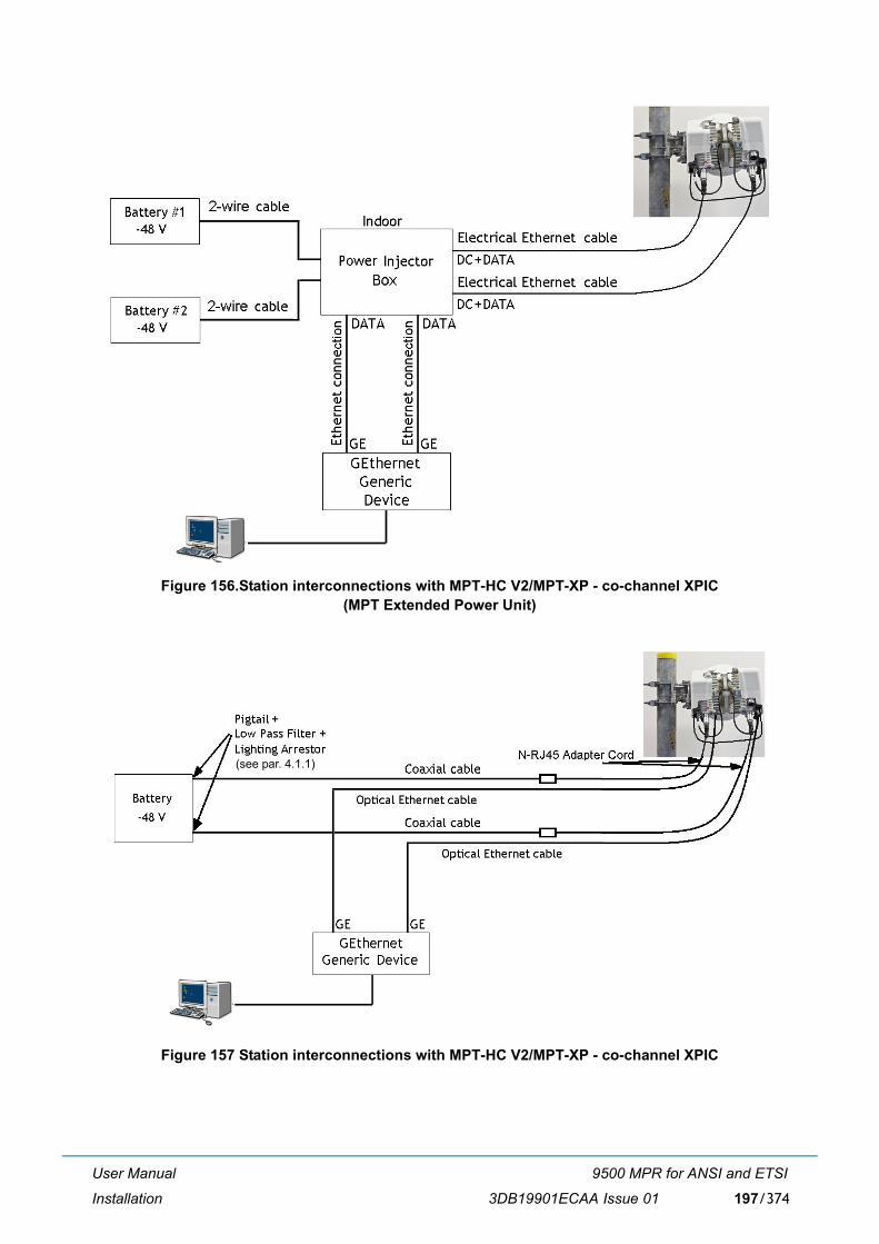
User Manual
Installation
9500 MPR for ANSI and ETSI
3DB19901ECAA Issue 01 197/374
Figure 156.Station interconnections with MPT-HC V2/MPT-XP - co-channel XPIC(MPT Extended Power Unit)
Figure 157 Station interconnections with MPT-HC V2/MPT-XP - co-channel XPIC
(see par. 4.1.1)

User Manual
Installation
9500 MPR for ANSI and ETSI
3DB19901ECAA Issue 01198/374
Figure 158 Station interconnection with MPT-HC V2/MPT-XP/9558HC -1+0 repeater configuration
4.1.1 How to connect the MPT-HC V2 to the battery
Figure 159 shows the devices used to connect a MPR-e directly to a battery.
Note: this type of powering is only possible when the connection to the MPR-e is by optical fiber.
From front to back:
� Coaxial cable with N connectors
� Wall mount support 3CC50149AAXX (max 4 MPT)
� Lightning arrestor with its grounding cable
� Low pass filter
� Cable N to two wires ("pigtail")
� Grounding kits
� Cable N to RJ-45 (�pigtail�)

User Manual
Installation
9500 MPR for ANSI and ETSI
3DB19901ECAA Issue 01 199/374
Figure 159 MPT-HC V2 directly connected to the battery
4.2 MPR-e in Single NE mode with 7705 SAR: installation & interconnection overview
The figures in this section describes the possible final hardware configurations of MPR-e in Single NEmode with 7705 SAR (applicable to 9500 MPR Release 4.1.0).
Figure 160 Station interconnections with MPT-MC/MPT-HC v2 (Power Injector card)
Figure 161 Station interconnections with MPT-HC V2 (MPT power unit)

User Manual
Installation
9500 MPR for ANSI and ETSI
3DB19901ECAA Issue 01200/374
Figure 162 Station interconnections with MPT-HC V2/MPT-XP (MPT Extended Power Unit)
Figure 163 Station interconnections with MPT-HC V2 - co-channel XPIC (7705 SAR)
Figure 164 Station interconnections with MPT-HC V2 � 1+1 Hot Standby
Note: For more detailed information on PMC ports pair supporting 1+1, see the 7705 SAR OS 6.0.R1documentation.

User Manual
Installation
9500 MPR for ANSI and ETSI
3DB19901ECAA Issue 01 201/374
Note: This solution applies with both the MPT Power unit and the MPT Extended power unit; seeFigure 161 and Figure 162 for connectivity reference for these solutions.
4.3 Hardware installation
� 4.3.1 - Power consumption on page 201
� 4.3.2 - MPT-HC V2/MPT-XP/9558HC installation on page 201
� 4.3.3 - MPT-MC installation on page 268
� 4.3.4 - Power injector on page 285
� 4.3.5 - Installation items on page 289
� 4.3.6 - Antenna alignment on page 294
4.3.1 Power consumption
Note: Figures are for normal (not start-up) operation.
4.3.2 MPT-HC V2/MPT-XP/9558HC installation
The MPT-HC V2/MPT-XP/9558HC installation section is divided in:
� Types of MPT-HC V2/MPT-XP/9558HC (par. 4.3.2.1 on page 203)
� Optional external module to be installed (par. 4.3.2.2 on page 204)
� MPT-HC V2/MPT-XP/9558HC operative information (par. 4.3.2.3 on page 207)
� How to change polarization in the MPT-HC V2/MPT-XP/9558HC (par. 4.3.2.4 on page 214)
Part Max. Power Consumption Typical Power Consumption
MPT-HC V2 39 W 37 W
MPT-HC V2 (with RPS module) 40 W 38 W
MPT-HC V2 (with XPIC-RPS module) 48 W 46 W
MPT-MC 40 W 38 W
MPT-XP 70 W 67 W
MPT-XP (with RPS module) 70 W 67 W
MPT-XP (with XPIC-RPS module)
78 W 73 W

User Manual
Installation
9500 MPR for ANSI and ETSI
3DB19901ECAA Issue 01202/374
� Types of Pole mounting installation kits (par. 4.3.2.5 on page 216)
� Types of nose adapters (par. 4.3.2.6 on page 218)
� Types of RF integrated OMTs (par. 4.3.2.8 on page 220)
� 1+0 MPT-HC V2/MPT-XP/9558HC installation (integrated antenna) (par. 4.3.2.9 on page 223)
� 1+0 MPT-HC V2/MPT-XP/9558HC installation (non integrated antenna) (par. 4.3.2.10 on page 226)
� OMT installation (par. 4.3.2.13 on page 244)
� Cable connections (MPT-HC V2/MPT-XP/9558HC) (par. 4.3.2.14 on page 254)
� Installing the �Flextwist� waveguide (non integrated antenna) (par. 4.3.2.16 on page 262)
� MPT-HC V2/MPT-XP/9558HC system grounding (par. 4.3.2.17 on page 264)
� Cable grounding (par. 4.3.2.18 on page 265)
� Type N connectors and grounding kits waterproofing on the IDU/ODU cables (par. 4.3.2.19 on page266)

User Manual
Installation
9500 MPR for ANSI and ETSI
3DB19901ECAA Issue 01 203/374
4.3.2.1 Types of MPT-HC V2/MPT-XP/9558HC
The MPT-HC V2/MPT-XP/9558HC consists of one cabinet including the Ethernet interface + modem +RF transceiver + branching of a channel.
Two mechanical solutions are adopted:
[1] with embedded diplexer for cost optimisation, shown in Figure 165, where the branching (diplexer)is internal to the MPT-HC V2 cabinet; this type of MPT-HC V2 is identified by one Logistical Itemonly;
[2] with external diplexer: due to a high number of shifters the diplexer is external for the flexibility of theshifter customization, where MPT-HC V2/MPT-XP/9558HC is composed by two independent units:the BRANCHING assembly (containing the diplexer) and the RF TRANSCEIVER assembly(containing the RF section); each of this type of MPT-HC V2/MPT-XP/9558HC is identified by twoLogistical Items, one for the BRANCHING assembly and another for the RF TRANSCEIVERassembly. To read the BRANCHING assembly identification label it is necessary to separate theBRANCHING assembly from the RF TRANSCEIVER assembly.
Figure 165 Views of MPT-HC V2 with embedded diplexer

User Manual
Installation
9500 MPR for ANSI and ETSI
3DB19901ECAA Issue 01204/374
4.3.2.2 Optional external module to be installed
The MPT-HC V2/MPT-XP/9558HC is delivered from the factory in one packing-case in the basicconfiguration (without any external module). The optional external module for the XPIC configuration(XPIC+RPS) is delivered in another packing-case.
The external module must be installed in field on the MPT-HC V2/MPT-XP/9558HC.
Note: Before installing an external module on a MPT-HC V2/MPT-XP/9558HC, the correspondingMPT-HC V2/MPT-XP/9558HC must be switched OFF. Switch ON can be done once the modulehas been properly screwed.
To install it follow the following procedure:
1) Disinstall the solar shield by unlocking the 3 screws.
2) Unlock the 4 screws with a screwdriver.
3) Remove the basic cover
4) Remove the cap.
Unlock the screws
Remove the cover

User Manual
Installation
9500 MPR for ANSI and ETSI
3DB19901ECAA Issue 01 205/374
5) Withdraw the external module from the packing-case (refer to Figure 166) and remove the cap.
Figure 166 XPIC + RPS module
Remove the cap
Remove the cap
Bottom view
Top view

User Manual
Installation
9500 MPR for ANSI and ETSI
3DB19901ECAA Issue 01206/374
6) Install the module on the MPT-HC V2/MPT-XP/9558HC. The MPT-HC V2/MPT-XP/9558HCcannot be on the pole mounting. MPT-HC V2/MPT-XP/9558HC should be placed on a table oron the floor. The 4 screws must be locked with a screwdriver respecting the following order 1� 2 � 3 � 4:
Figure 167 External module installed
Pay attention to the gasket that must be properly inserted in the groove to insure IP67protection.
Pay attention to the correct position of the screws, as shown in Figure 168. The slot of the screwmust be aligned with the indication on the MPT-HC V2/MPT-XP/9558HC.
Figure 168 Correct screw position
7) With RPS module, a SFP is needed for interconnection with RPS cable. If indoor-outdoor is afiber, a second SFP is needed.
8) Install the solar-shield taking into account the polarization to be used.
(1)
(2)
(4)
(3)
Indication

User Manual
Installation
9500 MPR for ANSI and ETSI
3DB19901ECAA Issue 01 207/374
4.3.2.3 MPT-HC V2/MPT-XP/9558HC operative information
This paragraph gives operative information, for installation regarding:
� MPT-HC V2/MPT-XP/9558HC with embedded or external diplexerbelow
� MPT-HC V2/MPT-XP/9558HC with external diplexer (additional information)on page 210
4.3.2.3.1 Operative information on MPT-HC V2/MPT-XP/9558HC with embedded or externaldiplexer
4.3.2.3.1.1 General, views and access points
Figure 169 on page 208 (for MPT-HC V2 with embedded diplexer) and Figure 170 on page 209 (forMPT-HC V2/MPT-XP/9558HC with external diplexer) show MPT-HC V2/MPT-XP/9558HC views andaccess points.
The external interfaces are listed in Table 57. below with the corresponding connectors.
Table 57. MPT-HC V2/MPT-XP/9558HC external interfaces
Table 58. RF interface
Ref. in Figure 169
and Figure 170
Interface Connector Further information
(1) RF interface Waveguide Connection to antenna. Refer to Table 58. herebelow
(2) Connector for power supply cable orfor PFoE (Power Supply + EthernetTraffic) cable
RJ45 + R2CT
(3) Optical Ethernet connection LC + Q-XCO Before to connect the cable insert the SFP (not included
in factory)
(4) RPS connector LC + Q-XCO Used in XPIC configuration. Before to connect the cable insert the SFP (not included
in factory)
(5) XPIC connector Proprietary connector Used in XPIC configuration
FREQUENCY GHz -> 5.8 6 7 8 10.5 11 13-15 18-26 38
Waveguide type -> WR137 WR137 WR112 WR112 WR75 WR75 WR62 WR42 WR28

User Manual
Installation
9500 MPR for ANSI and ETSI
3DB19901ECAA Issue 01208/374
Figure 169 Views of MPT-HC V2 with embedded diplexer
(A) Locking hooks (4) to fix/unfix MPT-HC V2 assembly to antenna or coupler
(1) RF interface for connection of antenna or coupler. Remove the plastic cover.
WARNING: A waterproofness tape is glued on the waveguide of the MPT-HC V2. It must neverbe removed.
Note: If the SFP does not have the bail latch, to extract it (if required) use the suitable tool.
(1) (A)
(A)(A)
(A)(3) (2)
MPT-HC V2 basic
(4)
(3) (2)
MPT-HC V2 equipped with XPIC-RPS module
(5)

User Manual
Installation
9500 MPR for ANSI and ETSI
3DB19901ECAA Issue 01 209/374
Figure 170 Views of MPT-HC V2/MPT-XP/9558HC with external diplexer
(A) 4 locking hooks to fix/unfix branching assembly (diplexer) to transceiver
(B) 4 locking hooks to fix/unfix branching assembly (diplexer) to antenna or coupler
(1) RF interface for connection of antenna or coupler. Remove the plastic cover.
WARNING: A waterproofness tape is glued on the waveguide of the MPT-HC V2/MPT-XP/9558HC. It must never be removed.
Note: If the SFP does not have the bail latch, to extract it (if required) use the suitable tool.
(1) (A)
(A)(A)
(A)
(B)(B)
(B)(B)
(4)
(3) (2)
MPT-HC V2 equipped with XPIC-RPS module
(5)
(3) (2)
MPT-HC V2 basic

User Manual
Installation
9500 MPR for ANSI and ETSI
3DB19901ECAA Issue 01210/374
4.3.2.3.2 Additional operative information on MPT-HC V2/MPT-XP/9558HC with external diplexer
4.3.2.3.2.1 MPT-HC V2/MPT-XP/9558HC composition
As shown in Figure 171, the MPT-HC V2/MPT-XP/9558HC assembly is made up of two boxes, one fordiplexer system (BRANCHING) and the other for the all other active functions (TRANSCEIVER)connected together to form the MPT-HC V2/MPT-XP/9558HC.
An O-RING present in the TRANSCEIVER box guarantees the MPT-HC V2/MPT-XP/9558HC assemblywaterproofness.
Note: This is a conductive O-RING and must be left dry. Do not wet it with silicon grease (silicongrease must be used only on O-ring between MPT-HC V2/MPT-XP/9558HC and antenna).
Figure 171 Composition of MPT-HC V2/MPT-XP/9558HC with external diplexer
WARNING 1: A waterproofness tape is glued on the waveguide of the MPT-HC V2/MPT-XP/9558HC. Itmust never be removed.
WARNING 2: This gasket must never be removed.
The TRANSCEIVER box performs all the functions, but does not include the diplexer system.
The BRANCHING box provides the interface between the pole mounting/antenna and theTRANSCEIVER.
The favorite solution foresees the possibility to change in field a spare part TRANSCEIVER withoutdisconnecting the BRANCHING box from the pole mounting/antenna. The TRANSCEIVER andBRANCHING boxes fixing and unfixing are obtained through the four levers.
BRANCHING TRANSCEIVER
WARNING 1 WARNING 2

User Manual
Installation
9500 MPR for ANSI and ETSI
3DB19901ECAA Issue 01 211/374
4.3.2.3.2.2 TRANSCEIVER and BRANCHING boxes coupling
Figure 172 below shows the TRANSCEIVER and BRANCHING boxes coupling surfaces:
� (A) BRANCHING box label informative contentdescribed in Figure 174 on page 213
� (B) (HIGH FREQ) and (C) (LOW FREQ) RF interfaces on BRANCHING box
� (D) (TX) and (E) (RX) RF interfaces on TRANSCEIVER box
The TRANSCEIVER and BRANCHING boxes can be coupled in two alternative ways (180°-rotated withrespect to each other):
� BRANCHING box (B) (HIGH FREQ) coupled to TRANSCEIVER box�s (D) (TX)in this case the TX part of the transceiver uses the HIGH frequency range of the Shifter set by theCraft Terminal (see field D in Figure 174 on page 213); obviously the RX part of the transceiver usesthe corresponding LOW frequency range;
� BRANCHING box (C) (LOW FREQ) coupled to TRANSCEIVER box�s (D) (TX)in this case the TX part of the transceiver uses the LOW frequency range of the Shifter set by theCraft Terminal (see field D in Figure 174 on page 213); obviously the RX part of the transceiver usesthe corresponding HIGH frequency range.
Figure 172 MPT-HC V2/MPT-XP/9558HC TRANSCEIVER and BRANCHING boxescoupling surfaces
Note: There is only one possible way to couple the BRANCHING box and the TRANSCEIVER box:there is a mistake-proofing put by the factory on the TRANSCEIVER box, whose positiondepends on the type of transceiver (low or high band, as shown in Figure 172) to ensure thatthe association with the BRANCHING box is always the right one.
(A) (B)
(C)
(D)
(E)Mistake-proofingHole

User Manual
Installation
9500 MPR for ANSI and ETSI
3DB19901ECAA Issue 01212/374
4.3.2.3.3 Labels affixed on the MPT-HC V2/MPT-XP/9558HC
a) The label depicted in Figure 173 below is affixed externally to all types of MPT-HC V2/MPT-XP/9558HC and MPT-HC V2/MPT-XP/9558HC TRANSCEIVER boxes;
b) Only for MPT-HC V2/MPT-XP/9558HC with external diplexers, an additional label, depicted in Figure174 on page 213, is placed on the branching assembly.
Figure 173 Label affixed on the MPT-HC V2/MPT-XP/9558HC and MPT-HC V2/MPT-XP/9558HC TRANSCEIVER box
SYMBOL OR WRITING MEANING
9500-MPR Equipment Acronym & Alcatel-Lucent Logo
CE European Community logo
! Not harmonized frequency logo
2002/96/EC WEEE (Waste Electrical andElectronic Equipment) Logo
-28 V / -58 V 1,5 A / 0,7 A Power supply range and current range
Logistical Item (shown numbers as examples) Logistical Item for Customer
A Logistical Item for Customer, bar code 128
Serial n° (shown numbers as examples) Factory Serial number
B Factory Serial number bar code 128
TX Frequency MHz (shown numbers as examples) Working frequency range
Shifter MHz (shown numbers as examples) Shifter
TX Sub-band (shown numbers as examples) TX Sub-band

User Manual
Installation
9500 MPR for ANSI and ETSI
3DB19901ECAA Issue 01 213/374
Figure 174 Label affixed inside the MPT-HC V2/MPT-XP/9558HC BRANCHING box
SYMBOL OR WRITING MEANING
ALU LOGO Alcatel-Lucent Logo
9500 MPR Equipment Acronym
C E European Community logo
0682 CETECOM Number
! Not Harmonized Frequency Logo
WEEE LOGO WEEE Logo
P/N / ICS 3DBXXXXXAAAA 01 Part Number + ICS
LOGISTICAL ITEM 3DBXXXXXAAXX Logistical Item
S.N. GA081528595 Serial number
A P/N + ICS Bar Code Alpha 128
B Logistical Item Bar Code Alpha 128
C Serial Number Bar Code Alpha 128
Shifter MHzTX
F min MHzF max MHz
Frequency Denomination

User Manual
Installation
9500 MPR for ANSI and ETSI
3DB19901ECAA Issue 01214/374
4.3.2.4 How to change polarization in the MPT-HC V2/MPT-XP/9558HC
4.3.2.4.1 MPT-HC V2 with embedded diplexer
Note: The polarization must be changed to match the antenna polarization and the coupler nosewaveguide.
The polarization must be turned to horizontal when assembling the MPT-HC V2 on an RFcoupler.
WARNING: A waterproofness tape is glued on the waveguide of the MPT-HC V2 and it must never beremoved.
Figure 175 MPT-HC V2 Change Polarization embedded diplexer
1 2
3
Remove the plastic protection cap from theMPT-HC V2.
Change the polarization of the MPT-HCV2, if required (default: verticalpolarization). To rotate the polarization usethe Allen wrench.
Horizontal polarization.
Protection cover
Unscrew the 2 screws

User Manual
Installation
9500 MPR for ANSI and ETSI
3DB19901ECAA Issue 01 215/374
4.3.2.4.2 MPT-HC V2/MPT-XP/9558HC with external diplexer
These MPT-HC V2/MPT-XP/9558HC have fixed polarization (vertical polarization). To change thepolarization it is necessary to change the antenna polarization and to install the MPT-HC V2/MPT-XP/9558HC 90° rotated.
Figure 176 MPT-HC V2/MPT-XP/9558HC Change Polarization external diplexer
1 2Example of vertical polarization. Example of horizontal polarization.

User Manual
Installation
9500 MPR for ANSI and ETSI
3DB19901ECAA Issue 01216/374
4.3.2.5 Types of Pole mounting installation kits
� Integrated antenna pole mounting installation kits
� Pole Mounting for Remote ODU installation kits
4.3.2.5.1 Integrated antenna pole mounting installation kits
These integrated antenna Pole Mounting kits are designed for quick mechanical installation, and:
� are included inside the chosen antenna kit.
� foresee the �Fine Tuning� for the positioning of the Antenna.
As shown in Figure 177, these integrated antenna Pole Mounting kits are supplied with the frequency-specific nose adapter for mounting the frequency-specific MPT-HC V2/MPT-XP/9558HC transceiver orRF Coupler.
In general, the nose adapter:
� in case of smallest antennas, is already mounted on the antenna
� in case of largest antennas, is supplied separately, and must be mounted on the antenna during theinstallation procedure.
Figure 177 Example of integrated antenna Pole Mounting (with antenna and nose adapter)

User Manual
Installation
9500 MPR for ANSI and ETSI
3DB19901ECAA Issue 01 217/374
4.3.2.5.2 Pole Mounting for Remote ODU installation kits
These kits are frequency independent, and provide only the mechanical support function. The frequencyspecialization is obtained mounting the frequency-specific nose adapter.
Figure 178 Pole Mounting for Remote ODU installation kit (3DB10137AAXX)
N.B.: The nose adapter shown is not included in the kit.

User Manual
Installation
9500 MPR for ANSI and ETSI
3DB19901ECAA Issue 01218/374
4.3.2.6 Types of nose adapters
In case of:
� integrated antenna configurations, the nose adapter is delivered inside the chosen antenna kit; inthis case the RF interface is used to attach the frequency-specific MPT-HC V2/MPT-XP/9558HCtransceiver or RF Coupler.
� Non Integrated Antenna configurations, the nose adapter is used to attach:
� at one side, the frequency-specific MPT-HC V2/MPT-XP/9558HC transceiver or RF Coupler
� at the other side, to attach the Flextwist cable toward the antenna.
In these Non Integrated Antenna configurations, the nose adapter is delivered as individual item, andmust be always mounted on the ODU or Coupler, during the installation procedure.
The mounting accessories are delivered with the nose adapter.

User Manual
Installation
9500 MPR for ANSI and ETSI
3DB19901ECAA Issue 01 219/374
4.3.2.7 Types of RF couplers
� RF couplers for 6-7-8 GHz bands
� RF couplers for bands from 11 to 38 GHz
4.3.2.7.1 RF couplers for 6-7-8 GHz bands
Table 59. Codes, characteristics and views of RF couplers for bands from 6 to 8 GHz
Figure 179 MPT-HC RF coupler views (Bands 6-7-8 GHz)
4.3.2.7.2 RF couplers for bands from 11 to 38 GHz
Code Description Waveguide (3 ports)
Coupler type Coupling loss
3CC58056AAXX 6 GHz 3 dB Coupler WR 137Bal. 3 dB / 3 dB
3CC14536ABAA 7.1�8.5 GHz 3 dB Coupler WR 112
3CC58056ABXX 6 GHz 10 dB Coupler WR 137Unbal. 1 dB / 10 dB
3CC14536AAXX 7.1�8.5 GHz 10 dB Coupler WR 112
Coupler weight = 6 Kg about

User Manual
Installation
9500 MPR for ANSI and ETSI
3DB19901ECAA Issue 01220/374
Table 60. Codes, characteristics and views of RF couplers for bands from 11 to 38 GHz
Figure 180 MPT-HC RF coupler view (Bands from 11 to 38 GHz)
4.3.2.8 Types of RF integrated OMTs
4.3.2.8.1 RF Integrated OMTs for the 6-7-8 GHz bands
Table 61. OMT coupler: characteristics and views of RF couplers for bands from 6 to 8 GHz
Code Description Waveguide(3 ports)
Coupler type
Coupling loss
3CC14140AAXX 11 GHz 3 dB Coupler WR 75
Bal. 3 dB / 3 dB3CC13472AAXX 13/15 GHz 3 dB Coupler WR 62
3CC13473AAXX 18/25 GHz 3 dB Coupler WR 42
3CC13474AAXX 38 GHz 3 dB Coupler WR 28
3CC14140ABXX 11 GHz 10 dB Coupler WR 75
Unbal. 1 dB / 10 dB3CC13472ABXX 13/15 GHz 10 dB Coupler WR 62
3CC13473ABXX 18/25 GHz 10 dB Coupler WR 42
3CC13474ABXX 38 GHz 10 dB Coupler WR 28
Coupler weight = 4.3 Kg about
Part number Description Freq range (GHz) Waveguide (ODU Ports)
3CC58134AAXX OMT 6 GHz L 5.9 - 6.4 WR137
3CC58186AAXX OMT 6 GHz U 6.4 - 7.1 WR137
3CC58124AAXX OMT 7 GHz 7.1 - 7.7 WR112

User Manual
Installation
9500 MPR for ANSI and ETSI
3DB19901ECAA Issue 01 221/374
Figure 181 MPT-HC V2/MPT-XP 6-7-8 GHz Integrated OMTs views
3CC58133AAXX OMT 8 GHz 7.7 - 8.5 WR112
OMTs weight = about 6 Kg

User Manual
Installation
9500 MPR for ANSI and ETSI
3DB19901ECAA Issue 01222/374
4.3.2.8.2 RF Integrated OMTs for the 11 to 23 GHz bands
Table 62. OMT couplers, characteristics and views of RF OMTs for bands from 11 to 23 GHz
Figure 182 MPT-HC V2 11 to 13 GHz Integrated OMTs views
Part number Description Freq range (GHz) Waveguide (ODU Ports)
3CC58161AAXX OMT 11 GHz 10.7 - 11.7 WR75
3CC58162AAXX OMT 13 GHz 12.7 - 13.3 WR62
3CC58163AAXX OMT 15 GHz 14.4 - 15.35 WR62
3CC58164AAXX OMT 18 GHz 17.7 - 19.7 WR42
3CC58165AAXX OMT 23 GHz 21.2 - 23.6 WR42
OMTs weight = about 4 Kg

User Manual
Installation
9500 MPR for ANSI and ETSI
3DB19901ECAA Issue 01 223/374
4.3.2.9 1+0 MPT-HC V2/MPT-XP/9558HC installation (integrated antenna)
[1] Check/Set the coupling between the TRANSCEIVER and BRANCHING boxes (only for MPT-HC V2/MPT-XP/9558HC with external diplexer).
[2] Install the Antenna and Pole Mounting.This pole mounting is delivered as �pole mounting�, �antenna�, and frequency-specific �noseadapter� already assembled. The integrated antenna is mounted on the pole front.Antenna and pole mounting must be installed in accordance with the manufacturer�s instructions.
[3] Check or change the polarization on the Antenna nose.To change the polarization, follow the instructions supplied with each antenna. 223 shows anexample.
Note: The antennas are normally supplied with vertical polarization.
Figure 183 Example of antenna polarization change (�1+0� MPT-HC V2/MPT-XP/9558HC integrated antenna)
[4] Take off the solar shield from the MPT-HC V2/MPT-XP/9558HC transceiver by unscrewing thescrews placed on the solar shield back panel.
[5] Install the MPT-HC V2/MPT-XP/9558HC on the Antenna nose adapter.
Note: Silicone grease must be put on the nose adapter O-ring when indicated in themanufacturer�s installation instructions. If grease for O-ring is not mentioned, it must beavoided.

User Manual
Installation
9500 MPR for ANSI and ETSI
3DB19901ECAA Issue 01224/374
Figure 184 Putting silicone grease on O-ring before MPT-HC V2/MPT-XP/9558HC insertion
1) Grasp the MPT-HC V2/MPT-XP/9558HC module by the handle.
2) Open the four looking hooks (1) arranged on the four walls of the MPT-HC V2/MPT-XP/9558HCunit.
3) For MPT-HC V2 with embedded diplexer, set the correct polarization.
4) Using the proper orientation for the MPT-HC V2/MPT-XP/9558HC, slide it on the nose adapter.For MPT-HC V2/MPT-XP/9558HC with external diplexers, rotate the MPT-HC V2/MPT-XP/9558HC depending on the horizontal or vertical polarization.
5) Secure the MPT-HC V2/MPT-XP/9558HC module through the four hooks (1) on the relativebrackets (2).
Figure 185 MPT-HC V2 1+0 installation for integrated antenna (embedded diplexer)
Apply silicone greasewhen necessary
(1) Hook
(2) Bracket

User Manual
Installation
9500 MPR for ANSI and ETSI
3DB19901ECAA Issue 01 225/374
Figure 186 MPT-HC V2/MPT-XP/9558HC 1+0 installation for integrated antenna (external diplexer: vertical polarization)
Figure 187 MPT-HC V2/MPT-XP/9558HC 1+0 installation for integrated antenna (external diplexer: horizontal polarization)
REMINDER: The MPT-HC V2/MPT-XP/9558HC/antenna assembly requires no additional seal onthe SHF flanges; the two ends are smooth. The O-ring seal around the male �nose� provides sealing.
[6] Ground the MPT-HC V2/MPT-XP/9558HC system.
[7] Pre-point the antenna.
(1) Hook
(2) Bracket
(1) Hook
(2) Bracket

User Manual
Installation
9500 MPR for ANSI and ETSI
3DB19901ECAA Issue 01226/374
[8] Reinstall the solar shield onto the MPT-HC V2/MPT-XP/9558HC transceiver by screwing on it thesolar shield screws.
[9] Affix the EMF stickers.
4.3.2.10 1+0 MPT-HC V2/MPT-XP/9558HC installation (non integrated antenna)
[1] Check/Set the coupling between the TRANSCEIVER and BRANCHING boxes (only for MPT-HC V2/MPT-XP/9558HC with external diplexer).
[2] Install the Nose Adapter on the �Pole Mounting for Remote ODU�.
[3] Install the �Pole Mounting for Remote ODU�.Pole mounting must be installed in accordance with the manufacturer�s instructions.In case of missing instructions, fix the U-bolts with 34 N x m tightening torque.
Note: The pole mounting can be installed on the Right or Left hand side of the pole dependingon the azimuth and on the configuration of the tower.
Figure 188 "Pole Mounting for Remote ODU" installation
[4] Take off the solar shield from the MPT-HC V2/MPT-XP/9558HC transceiver by unscrewing thescrews placed on the solar shield back panel.
[5] Install the MPT-HC V2/MPT-XP/9558HC.
Note: Silicone grease must be put on the nose adapter O-ring when indicated in themanufacturer�s installation instructions. If grease for O-ring is not mentioned, it must beavoided.

User Manual
Installation
9500 MPR for ANSI and ETSI
3DB19901ECAA Issue 01 227/374
Figure 189 Putting silicone grease on O-ring before MPT-HC V2/MPT-XP/9558HC insertion
1) Grasp the MPT-HC V2/MPT-XP/9558HC module by the handle. Open the four looking hooksarranged on the four walls of the MPT-HC V2/MPT-XP/9558HC unit.
2) Position the Pole mounting support on the pole side as shown in the plant documentation.
3) Position the MPT-HC V2/MPT-XP/9558HC and slide it on the nose adapter.
4) Secure the MPT-HC V2/MPT-XP/9558HC module through the four hooks onto the relativebrackets.
Figure 190 MPT-HC V2/MPT-XP/9558HC 1+0 installation for not integrated antenna (embedded diplexer with pole mounting P/N 3DB10137AAXX)
Apply silicone greasewhen necessary.

User Manual
Installation
9500 MPR for ANSI and ETSI
3DB19901ECAA Issue 01228/374
Figure 191 MPT-HC V2/MPT-XP/9558HC 1+0 installation for not integrated antenna(external diplexer with pole mounting P/N 3DB10137AAXX)
[6] Install the external Antenna with its own Pole Mounting.The installation of the antenna and of its own pole mounting, as well as the antenna polarizationcheck/change, must be done in accordance with the manufacturer�s instructions.
[7] Connect the antenna side (flange) of the Pole Mounting�s nose adapter to the external antenna, bymeans of the �Flextwist� waveguide. (Refer to par. 4.3.2.16).
[8] Ground the MPT-HC V2/MPT-XP/9558HC system.
[9] Pre-point the antenna.
[10] Reinstall the solar shield onto the MPT-HC V2/MPT-XP/9558HC transceiver by screwing on it thesolar shield screws.
[11] Affix the EMF stickers.
4.3.2.11 1+1 MPT-HC installation (integrated antenna)
4.3.2.11.1 Coupler installation
4.3.2.11.1.1 11-38 GHz
[1] Install the Antenna and Pole Mounting.This pole mounting is delivered as �pole mounting�, �antenna�, and frequency-specific �noseadapter� already assembled. The integrated antenna is mounted on the pole front.Antenna and pole mounting must be installed in accordance with the manufacturer�s instructions.
[2] Check or change the polarization of the RF coupler.The axial adaptation between H polarization to V polarization (and vice versa) is a mechanical/electrical adjustment. Every mechanical �STEP� is a 30° adjustment.

User Manual
Installation
9500 MPR for ANSI and ETSI
3DB19901ECAA Issue 01 229/374
Figure 192 Coupler Polarization Change (11-38 GHz) - 1st Step and 2nd step
The final result must be as shown in Figure 195 on page 230 (example for V polarization): theengraved polarization symbols (H or V) must coincide with the reference blind hole.
Change Polarization Procedure
1) 1st Step = internal 30° rotate
Figure 193 Coupler Polarization Change (11-38 GHz) - 1st Step execution
2) 2nd Step= cover + screws 60°(30°+ 30°) rotate

User Manual
Installation
9500 MPR for ANSI and ETSI
3DB19901ECAA Issue 01230/374
Figure 194 Coupler Polarization Change (11-38 GHz) - 2nd Step execution
The �spigot� in the integrated antenna configuration is 30° and complete the change of polarization(90°).
Figure 195 Coupler Polarization Change (11-38 GHz) - Screws fixing
[3] Install the RF coupler on antenna�s nose adapter.
N.B. Silicon grease must be put on the antenna�s nose adapter O-ring when indicated in themanufacturer's installation instructions. If grease for O-ring is not mentioned, it must beavoided

User Manual
Installation
9500 MPR for ANSI and ETSI
3DB19901ECAA Issue 01 231/374
Figure 196 Putting silicone grease on O-ring before RF coupler insertion (11-38 GHz)
Grasp the coupler by the handle. Fasten the coupler to the support through the four locking hooksthat will be tightened onto the relative fastening brackets on the radio support. The label correspondsto the side of the pole.
Figure 197 Installing the RF coupler to the radio support (11-38 GHz)
WARNING: verify that the indication , engraved on the coupler, is directed toward the sidepole:
[4] For each MPT-HC transceiver, take off the solar shield by unscrewing the screws placed on the solarshield back panel.
Apply silicone greaseas required.

User Manual
Installation
9500 MPR for ANSI and ETSI
3DB19901ECAA Issue 01232/374
[5] Install the MPT-HC transceivers on the RF coupler.
N.B. Silicon grease must be put on the RF coupler�s nose adapter O-ring when indicated in themanufacturer's installation instructions. If grease for O-ring is not mentioned, it must beavoided
Figure 198 Putting silicone grease on RF coupler�s O-ring before MPT-HC insertion (11-38 GHz)
Grasp each MPT-HC by the handle. Fasten the MPT-HC module to the support through the lockinghooks that will be tightened onto the relative fastening bracket on the coupler.
N.B. Remember to set the correct polarization on the MPT-HC to match the coupler nosewaveguide.
Figure 199 Installing the MPT-HC 1+1 on the RF coupler (11-38 GHz)
Figure 200 shows the final result, and indicates the position of the MAIN and PROTECTION MPT-HC.
Apply silicone greaseas required.

User Manual
Installation
9500 MPR for ANSI and ETSI
3DB19901ECAA Issue 01 233/374
Figure 200 Views of MPT-HC 1+1 integrated antenna after installation (11-38 GHz)
[6] Ground the MPT-HC system.
[7] Pre-point the antenna.
[8] Reinstall the solar shield onto each MPT-HC transceiver by screwing on it the solar shield screws.
[9] Affix the EMF stickers.
4.3.2.11.1.2 6-7-8 GHz
[1] Check/Set the coupling between the TRANSCEIVER and BRANCHING boxes (only for MPT-HCwith external diplexer).
[2] Install the Antenna and Pole Mounting.This pole mounting is delivered as �pole mounting�, �antenna�, and frequency-specific �noseadapter� already assembled. The integrated antenna is mounted on the pole front.Antenna and pole mounting must be installed in accordance with the manufacturer�s instructions.
[3] Check or change the polarization of the RF coupler (solution A).
WARNING: A waterproofness tape is glued on the waveguide of the coupler and it must never beremoved.
a) Vertical Polarization to Horizontal PolarizationThe point of reference is on the position V (Vertical Polarization).To change the polarization, perform the following operations:1) Unscrew the three screws.2) Turn the thin twist and to make to coincide the position H to the point of reference �A�3) Screw the screws.
b) Horizontal Polarization to Vertical PolarizationThe point of reference is on the position H (Horizontal Polarization).To change the polarization, perform the following operations:4) Unscrew the three screws.5) Turn the thin twist and to make to coincide the position V to the point of reference �A�6) Screw the screws.

User Manual
Installation
9500 MPR for ANSI and ETSI
3DB19901ECAA Issue 01234/374
Figure 201 Coupler Polarization Change (6-7-8 GHz)
[4] Check or change the polarization of the RF coupler (solution B).
WARNING: A waterproofness tape is glued on the waveguide of the coupler and it must never beremoved.
1
2 Vertical polarization
Unscrew the screws

User Manual
Installation
9500 MPR for ANSI and ETSI
3DB19901ECAA Issue 01 235/374
[5] Install the RF coupler on antenna�s nose adapter.
N.B. Silicon grease must be put on the antenna�s nose adapter O-ring when indicated in themanufacturer's installation instructions. If grease for O-ring is not mentioned, it must beavoided
Grasp the coupler by the handle. Fasten the coupler to the support through the four locking hooksthat will be tightened onto the relative fastening brackets on the radio support. The label correspondsto the side of the pole.
3 4
5 6
Remove the disk.
Rotate clockwise the disk on the bottom. Upset the removed disk in order to showthe side with H indication.
7 Reinsert the disk by setting letter H as in the figure.

User Manual
Installation
9500 MPR for ANSI and ETSI
3DB19901ECAA Issue 01236/374
Figure 202 Installing the RF coupler to the radio support (6-7-8 GHz)
[6] For each MPT-HC transceiver, take off the solar shield by unscrewing the screws placed on the solarshield back panel.
[7] Install the MPT-HC transceivers on the RF coupler.
N.B. Silicon grease must be put on the RF coupler�s nose adapter O-ring when indicated in themanufacturer's installation instructions. If grease for O-ring is not mentioned, it must beavoided
Figure 203 Putting silicone grease on O-ring before MPT-HC insertion (6-7-8 GHz)
Grasp the MPT-HC transceiver by the handle, and fasten it to the coupler support through the fourlocking hooks that will be tightened onto the relative fastening brackets on coupler.
Apply silicone greaseas required.
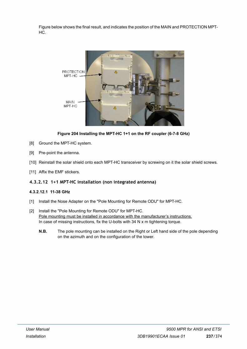
User Manual
Installation
9500 MPR for ANSI and ETSI
3DB19901ECAA Issue 01 237/374
Figure below shows the final result, and indicates the position of the MAIN and PROTECTION MPT-HC.
Figure 204 Installing the MPT-HC 1+1 on the RF coupler (6-7-8 GHz)
[8] Ground the MPT-HC system.
[9] Pre-point the antenna.
[10] Reinstall the solar shield onto each MPT-HC transceiver by screwing on it the solar shield screws.
[11] Affix the EMF stickers.
4.3.2.12 1+1 MPT-HC installation (non integrated antenna)
4.3.2.12.1 11-38 GHz
[1] Install the Nose Adapter on the "Pole Mounting for Remote ODU" for MPT-HC.
[2] Install the "Pole Mounting for Remote ODU" for MPT-HC.Pole mounting must be installed in accordance with the manufacturer�s instructions.In case of missing instructions, fix the U-bolts with 34 N x m tightening torque.
N.B. The pole mounting can be installed on the Right or Left hand side of the pole dependingon the azimuth and on the configuration of the tower.

User Manual
Installation
9500 MPR for ANSI and ETSI
3DB19901ECAA Issue 01238/374
Figure 205 "Pole Mounting for Remote ODU" installation
[3] Install the RF coupler on the nose adapter.
N.B. Silicon grease must be put on the nose adapter O-rings when indicated in themanufacturer's installation instructions. If grease for O-ring is not mentioned, it must beavoided.
Figure 206 Putting silicone grease on O-ring before RF coupler insertion
Grasp the coupler by the handle. Fasten the coupler to the support through the four locking hooksthat will be tightened onto the relative fastening brackets on the Pole Mounting.
Apply siliconegrease as required.

User Manual
Installation
9500 MPR for ANSI and ETSI
3DB19901ECAA Issue 01 239/374
Figure 207 11-38 GHz RF coupler installation (with pole mounting P/N 3DB10137AAXX)
[4] For each MPT-HC transceiver, take off the solar shield by unscrewing the screws placed on the solarshield back panel.
[5] Install the MPT-HC transceivers on the RF coupler.
N.B. Silicon grease must be put on the nose adapter O-rings when indicated in themanufacturer's installation instructions. If grease for O-ring is not mentioned, it must beavoided.
Warning: Lock the 4 hooks.

User Manual
Installation
9500 MPR for ANSI and ETSI
3DB19901ECAA Issue 01240/374
Figure 208 Putting silicone grease on RF coupler�s O-ring before MPT-HC insertion (11-38 GHz)
Grasp each MPT-HC by the handle. Fasten the MPT-HC module to the support through the lockinghooks that will be tightened onto the relative fastening bracket on the coupler.
Figure below shows the final result, and indicates the MAIN MPT-HC and the PROTECTION MPT-HC.
Figure 209 Installation of MPT-HC 1+1 (11-38 GHz)
[6] Install the external Antenna with its own Pole Mounting.The installation of the antenna and of its own pole mounting, as well as the antenna polarizationcheck/change, must be done in accordance with the manufacturer�s instructions.
Apply silicone greaseas required.
RF couplerPROTECTION
MPT-HCMAIN
MPT-HC

User Manual
Installation
9500 MPR for ANSI and ETSI
3DB19901ECAA Issue 01 241/374
[7] Connect the antenna side (flange) of the MPT-HC Pole Mounting�s nose adapter to the externalantenna, by means of the �Flextwist� waveguide. (Refer to par. 4.3.2.16).
[8] Ground the MPT-HC system.
[9] Pre-point the antenna.
[10] Reinstall the solar shield onto each MPT-HC transceiver by screwing on it the solar shield screws.
[11] Affix the EMF stickers.
4.3.2.12.2 6-7-8 GHz
[1] Check/Set the coupling between the TRANSCEIVER and BRANCHING boxes (only for MPT-HCwith external diplexer).
[2] Install the Nose Adapter on the "Pole Mounting for Remote ODU" for MPT-HC.
[3] Install the "Pole Mounting for Remote ODU" for MPT-HC.Pole mounting must be installed in accordance with the manufacturer�s instructions.In case of missing instructions, fix the U-bolts with 34 N x m tightening torque.
N.B. The pole mounting can be installed on the Right or Left hand side of the pole dependingon the azimuth and on the configuration of the tower.
Figure 210 "Pole Mounting for Remote ODU" installation
[4] Install the RF coupler on the nose adapter.
N.B. Silicon grease must be put on the nose adapter O-rings when indicated in themanufacturer's installation instructions. If grease for O-ring is not mentioned, it must beavoided.

User Manual
Installation
9500 MPR for ANSI and ETSI
3DB19901ECAA Issue 01242/374
Figure 211 Putting silicone grease on O-ring before RF coupler insertion
Grasp the coupler by the handle. Fasten the coupler to the support through the four locking hooksthat will be tightened onto the relative fastening brackets on the Pole Mounting.
Figure 212 6-7-8 GHz RF coupler installation (with pole mounting P/N 3DB10137AAXX)
[5] For each MPT-HC transceiver, take off the solar shield by unscrewing the screws placed on the solarshield back panel.
[6] Install the MPT-HC transceivers on the RF coupler.
N.B. Silicon grease must be put on the nose adapter O-rings when indicated in themanufacturer's installation instructions. If grease for O-ring is not mentioned, it must beavoided.
Apply silicone greaseas required.

User Manual
Installation
9500 MPR for ANSI and ETSI
3DB19901ECAA Issue 01 243/374
Figure 213 Putting silicone grease on O-ring before MPT-HC insertion (6-7-8 GHz)
Grasp the MPT-HC transceiver by the handle, and fasten it to the coupler support through the fourlocking hooks that will be tightened onto the relative fastening brackets on coupler.
Figure 214 Installing the MPT-HC 1+1 on the RF coupler (7-8 GHz)
Figure 215 shows the final result, and indicates the MAIN and PROTECTION MPT-HC.
Apply siliconegrease asrequired.
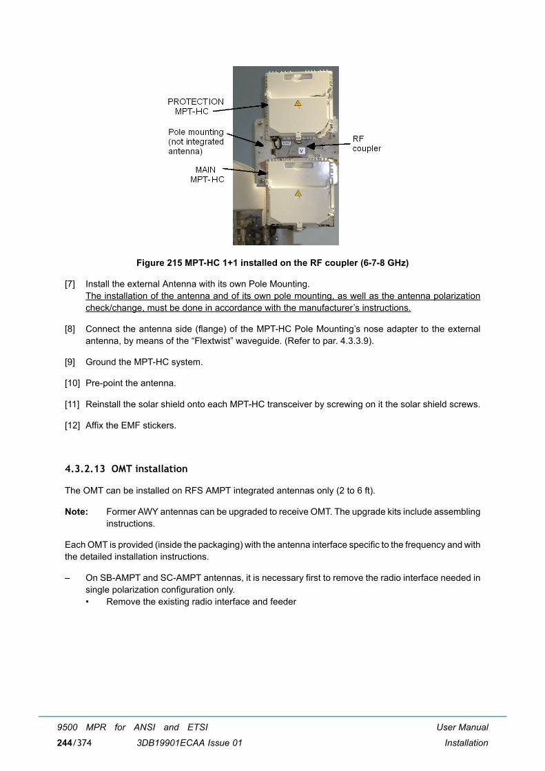
User Manual
Installation
9500 MPR for ANSI and ETSI
3DB19901ECAA Issue 01244/374
Figure 215 MPT-HC 1+1 installed on the RF coupler (6-7-8 GHz)
[7] Install the external Antenna with its own Pole Mounting.The installation of the antenna and of its own pole mounting, as well as the antenna polarizationcheck/change, must be done in accordance with the manufacturer�s instructions.
[8] Connect the antenna side (flange) of the MPT-HC Pole Mounting�s nose adapter to the externalantenna, by means of the �Flextwist� waveguide. (Refer to par. 4.3.3.9).
[9] Ground the MPT-HC system.
[10] Pre-point the antenna.
[11] Reinstall the solar shield onto each MPT-HC transceiver by screwing on it the solar shield screws.
[12] Affix the EMF stickers.
4.3.2.13 OMT installation
The OMT can be installed on RFS AMPT integrated antennas only (2 to 6 ft).
Note: Former AWY antennas can be upgraded to receive OMT. The upgrade kits include assemblinginstructions.
Each OMT is provided (inside the packaging) with the antenna interface specific to the frequency and withthe detailed installation instructions.
� On SB-AMPT and SC-AMPT antennas, it is necessary first to remove the radio interface needed insingle polarization configuration only.� Remove the existing radio interface and feeder

User Manual
Installation
9500 MPR for ANSI and ETSI
3DB19901ECAA Issue 01 245/374
� Detach the feeder and feeder plate.
� On SBX-AMPT and SCX-AMPT antennas the radio interface is not present.� The feeder and the feeder plate must be reassembled on the new OMT interface (see
paragraphs 4.3.2.13.1 or 4.3.2.13.2).
4.3.2.13.1 6, 7 and 8 GHz
[1] Assemble the feeder and the feeder plate on the OMT antenna interface.
[2] Insert the assembly in the antenna and screw it. Add the fine tuning screw with nylon spacer andwasher plus the special HEX spacer.

User Manual
Installation
9500 MPR for ANSI and ETSI
3DB19901ECAA Issue 01246/374
[3] Before inserting the OMT into the receptacle, apply silicone grease on the O-Ring when indicatedin the manufacturer�s installation instructions.
Note: Silicone grease must be put on the receptacle O-ring when indicated in the manufacturer�sinstallation instructions. If grease for O-ring is not mentioned, it must be avoided.
[4] Attach the OMT to the Interface without tightening the screws.
[5] Fix the fine tuning plate to the OMT body on the side opposite to the pole (see next picture).
Apply silicone greasewhen necessary beforeinserting the OMT

User Manual
Installation
9500 MPR for ANSI and ETSI
3DB19901ECAA Issue 01 247/374
[6] Install the MPT-HC V2/MPT-XP transceivers on the RF OMT.
Note: Silicone grease must be put on the OMT nose adapter O-ring when indicated in themanufacturer�s installation instructions. If grease for O-ring is not mentioned, it must beavoided.
Note: Before the installation, the MPT-HC V2/MPT-XP transceiver polarization must correspondto the polarization of each OMT receptacle (a proper indication close to each receptaclefacilitates the identification). To change the transceiver polarization, if required, follow theindications in paragraph 4.3.2.4 on page 214.
Steel plate for the finetuning mechanism

User Manual
Installation
9500 MPR for ANSI and ETSI
3DB19901ECAA Issue 01248/374
Grasp the MPT-HC V2/MPT-XP by the handle and fasten it to the OMT through the four lockinghooks that will be tightened onto the corresponding fastening brackets on the OMT.
Fine tuning procedure for polarization alignment
The OMT to interface fixation screws must be tightened once the OMT body is in precise vertical positionrespect to the ground. Then, the antenna pointing procedure must be performed. It consists in finding thebest antenna position to minimize the contra-polar received signal, acting on the pole mount tuningscrews.
Once completed the antenna pointing procedure, the fine tuning procedure must be applied to one of thefacing antennas to align the polarizations. Use the receiver on the polarization opposed to the transmitteron the facing antenna.
[1] Switch to the cross polar receiver.
[2] Release a little the OMT to interface fixation screws.
[3] Monitor the received cross polar signal and act on the special HEX spacer of the fine tuningmechanism of the OMT till the received signal power reaches its minimum (Power XP 30dB belowthe homopolar received signal).

User Manual
Installation
9500 MPR for ANSI and ETSI
3DB19901ECAA Issue 01 249/374
[4] Tighten the OMT fixing screws.
4.3.2.13.2 11 to 23 GHz
[1] Assemble the feeder and the feeder plate on the OMT antenna interface.
[2] Insert the assembly in the antenna and attach it with a screw it. Add the steel angular tuning part.
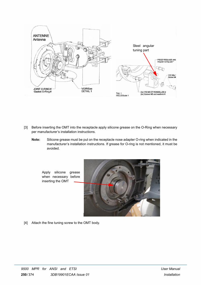
User Manual
Installation
9500 MPR for ANSI and ETSI
3DB19901ECAA Issue 01250/374
[3] Before inserting the OMT into the receptacle apply silicone grease on the O-Ring when necessaryper manufacturer�s installation instructions.
Note: Silicone grease must be put on the receptacle nose adapter O-ring when indicated in themanufacturer�s installation instructions. If grease for O-ring is not mentioned, it must beavoided.
[4] Attach the fine tuning screw to the OMT body.
Steel angulartuning part
Apply silicone greasewhen necessary beforeinserting the OMT

User Manual
Installation
9500 MPR for ANSI and ETSI
3DB19901ECAA Issue 01 251/374
[5] Place and fix the OMT to the Interface without tightening the screws.
Note: Take care to place the OMT with the engraved ARROW indicating the pipe towards thepipe itself.

User Manual
Installation
9500 MPR for ANSI and ETSI
3DB19901ECAA Issue 01252/374
[6] Install the MPT-HC V2/MPT-XP transceivers on the RF OMT.
Note: Silicone grease must be put on the nose adapter O-ring when indicated in themanufacturer�s installation instructions. If grease for O-ring is not mentioned, it must beavoided.
Grasp the MPT-HC V2/MPT-XP by the handle and fasten it to the OMT with the four locking hooksthat will be tightened onto the corresponding fastening brackets on the OMT.

User Manual
Installation
9500 MPR for ANSI and ETSI
3DB19901ECAA Issue 01 253/374
Fine tuning procedure for polarization alignment
The OMT to interface fixation screws must be tightened once the OMT body is in precise vertical positionrespect to the ground. Then, the antenna pointing procedure must be performed. It consists in finding thebest antenna position to minimize the contra-polar received signal, acting on the pole mount tuningscrews.
After the antenna pointing procedure is completed, you need to apply the fine tuning procedure to oneof the facing antennas to align the polarizations. Use the receiver on the polarization opposed to thetransmitter on the facing antenna.
[1] Switch to the cross polar receiver.
[2] Slightly loosen the OMT to interface fixation screws.
[3] Monitor the received cross polar signal and act on the special HEX spacer of the fine tuningmechanism of the OMT till the received signal power reaches its minimum (Power XP 30dB belowthe homopolar received signal).

User Manual
Installation
9500 MPR for ANSI and ETSI
3DB19901ECAA Issue 01254/374
[4] Tighten the OMT fixing screws.
4.3.2.14 Cable connections (MPT-HC V2/MPT-XP/9558HC)
4.3.2.14.1 Electrical Ethernet cable
If the PFoE has been implemented, only one cable interconnects the MPT-HC V2/MPT-XP/9558HC withthe Power Injector or MPT Extended Power Unit.
4.3.2.14.1.1 To terminate the Ethernet cable (MPT-HC V2/MPT-XP/9558HC side) and to pull it upfrom Indoor to MPT-HC V2/MPT-XP/9558HC
Warning: to make sure of the continuity and avoid short circuit, all cables / connectors connections suchas RJ45, Coaxial, Ethernet, or Optical Fiber made on the field have to be verified and checked with Cabletester. The waterproofness must be also checked.
To terminate the cable the kit plug R2CT must be used.
The kit is made up of 10 items as shown in Figure 217
Figure 216 Kit plug R2CT

User Manual
Installation
9500 MPR for ANSI and ETSI
3DB19901ECAA Issue 01 255/374
Figure 217 Kit plug R2CT items
4.3.2.14.2 Mating sequence instructions
To terminate and to connect the cable to the MPT-MC follow the instructions:

User Manual
Installation
9500 MPR for ANSI and ETSI
3DB19901ECAA Issue 01256/374
1 2Turn and remove the protection cap. Unscrew partially the nut spiral.
3 Pass the cable through the mini kit plug and crimp the RJ45 plug according to the standard
Terminate the Ethernet cable according to EIA/TIA 568B STANDARD. Follow theinstructions included with the connector.

User Manual
Installation
9500 MPR for ANSI and ETSI
3DB19901ECAA Issue 01 257/374
6 If you need to hoist the assembly, pull the coupling nut so as to cover the plug body and put backthe protection cap on
7 Tighten the nut spiral with a 21 mm wrench with a torque of 3N.m mini and 3,5 maxi. The cableis now fixed with the plug and ready to be pulled.
8 Install the cable then unscrew partially the nut spiral and remove the protection cap to connectto the receptacle
4 5Insert the RJ45 plug inside the unlockingclip (keep attention to have the latchesmechanisms on the same side)
Pull the cable and insert the unlocking cliptogether with the RJ45 plug inside the
body, the latches being aligned with the bodybayonet pin. Place the body arm on the left side.

User Manual
Installation
9500 MPR for ANSI and ETSI
3DB19901ECAA Issue 01258/374
4.3.2.14.3 Unmating sequence instructions
11 Secure the assembly by screwing the nutspiral with a 21mm wrench with a torque of3 N.m mini and 3,5 N.m maxi
12Push and rotate clockwise the coupling nutuntil secured onto the receptacle
9 10Align the two marks on the plug body andthe receptacle, insert and rotate clockwisethe plug body into the receptacle
Connect the RJ45 plug to its socket bypushing the cable.
1 2Unscrew the nut spiral via 21 mm adaptedwrench.
Rotate and unlock the coupling nut.

User Manual
Installation
9500 MPR for ANSI and ETSI
3DB19901ECAA Issue 01 259/374
4.3.2.14.4 Optical cable connection
An optical cable must be used, if the PFoE has not been implemented.
Note: First the SFP must be inserted in the MPT. The SFP is not included in the MPT.
The cable is shown in Figure 218. The cable is a preassembled cable available in different lengths (referto paragraph 4.3.5.2 on page 289).
Figure 218 LC/Q-XCO to LC Fiber cord
To pull-up the cable take a cord and insert it in the slot of the cable cap. Make a knot on the cord and pull-up the cable.
3 Engage the RJ45 unlocking clip forwarduntil front stop.
Press on the unlocking clip latch.4
5 6Pull the clip and the cable rearward todisconnect the RJ45 plug.
Rotate and disconnect the R2CT plug body.

User Manual
Installation
9500 MPR for ANSI and ETSI
3DB19901ECAA Issue 01260/374
Remove the cap and connect the connector to the �LC+Q-XCO� connector in the MPT-HC V2/MPT-XP/9558HC.
The overlength of the optical fiber must be rolled up in the Cable overlength box. Fix the Fiber on the poleor the tower with UV tie raps. See Figure 219.
Figure 219 Fiber cable overlength box
For the 1+0 repeater configuration, LC/Q-XCO cable (3CC52169XXXX) is required for ODU-ODUconnection.
4.3.2.14.5 Power supply cable connection
The power supply cable is a coaxial cable, which is used only if the optical cable is used to transport theEthernet traffic. Two types of coaxial cables are available according to the length (less than 200 m or 200m to 350 m).
The coaxial cable must be connected to:
� Indoor side: to the Station battery through the Lightning protection + Low Pass Filter + Pigtail N-to-2 wires. See par. 4.1.1 on page 198.
� ODU-side to the N-to-Ethernet pair pigtail (+ RJ45 + R2CT). The R2CT must be then connected tothe relevant connector on the MPT-HC V2/MPT-XP/9558HC. For the termination of the cable withRJ45 and R2CT refer to par. 4.3.2.14.1.
Warning: The Power Supply connection must be made waterproof (see par. 4.3.2.19 on page 266):
1) Surround the connector with the auto amalgamate tape from up to down
2) Surround the connector with the adhesive tape from up to down
3) Put tie raps on the up and the down of the connector

User Manual
Installation
9500 MPR for ANSI and ETSI
3DB19901ECAA Issue 01 261/374
4.3.2.15 Cable connection in XPIC configuration
The two MPT-HC V2/MPT-XP must be linked with the XPIC cable and with the RPS cable.
The XPIC cable is a cat7 cable with proprietary connectors.
Three lengths are available: 1 m, 2.5 m, 8 m, to be chosen depending on the way the MPT-HC V2/MPT-XPare installed.
The RPS cable is an LC-LC optional jumper preassembled with Q-XCO (1m length).
Figure 220 XPIC connector position
Figure 221 XPIC cable interconnection
Note: The extra length of the RPS and XPIC cables must be bound by using tie-raps, either on thepole or on the other cables coming from the ODUs.
XPIC connector
XPIC cable
RPS cable

User Manual
Installation
9500 MPR for ANSI and ETSI
3DB19901ECAA Issue 01262/374
4.3.2.16 Installing the �Flextwist� waveguide (non integrated antenna)
Concerning the interface between the MPT-HC V2/MPT-XP output flange and the suggested antennaflange, the following Table 63. details for each product the standard wave guide to be used and thesuggested flange for the external antenna.
Please note that the use of 600 mm flex twist is not suggested for antennas bigger than 3ft (90 cmdiameter), due to mechanical reasons. The suggested way to make the RF connection is to use theelliptical wave guide fitted with flanged connectors.
Table 63. MPT-HC V2/MPT-XP/9558HC Output flanges with external antenna
The long twistable flexible waveguide is supplied complete with gaskets and fasteners. At one end, it hasa smooth square or rectangular flange (to be mounted on the antenna) and at the other end, a groovedsquare flange designed to accommodate an O�ring seal (mounted at the MPT-HC V2/MPT-XP/9558HCend).
Range (GHz)
MPT-HC V2/MPT-XP/9558HC Output Flange
FLEXTWIST Suggested Antenna Flange
C.E.I. E.I.A.
6 UBR70 R70 WR137 PDR70 UDR70 PDR70
7-8
UDR84 R84 WR112 PDR84 UBR84 PBR84
or
UBR84 R84 WR112 PBR84 UBR84 PBR84
11 UBR100 R100 WR90 PBR100 UBR100 PBR100
13 UBR120 R120 WR75 PBR120 UBR120 PBR120
15 UBR140 R140 WR62 PBR140 UBR140 PBR140
18
UBR220 R220 WR42 PBR220 UBR220 PBR22023
26
38 UBR320 R320 WR28 PBR320 UBR320 PBR320

User Manual
Installation
9500 MPR for ANSI and ETSI
3DB19901ECAA Issue 01 263/374
Table 64. Flextwist waveguide
Note: If the FLEX�TWIST is not provided by Alcatel-Lucent, the user must carefully choose the typeof the connection guide in order to limit as much as possible galvanic couples betweenANTENNA/flex�twist and flex�twist/MPT-HC V2/MPT-XP/9558HC contact surfaces that caninduce rust. For this purpose please note that the surfaces are:
� chromium-plated at MPT-HC V2/MPT-XP/9558HC output flange side
� tin-plated at flex-twist�s flange side
FLEXIBLE TWISTABLE WAVEGUIDE KIT
Alc
atel
-Luc
ent
Par
t num
ber
Wav
egui
de
Leng
th m
m.
Freq
. Ban
d G
Hz
Flan
ges
Stai
nles
s st
eel
sock
et c
ap s
crew
s
Stai
nles
s st
eel
sock
et c
ap s
crew
s
�Ond
ufle
x� s
prin
gy
crin
kle
was
hers
Stai
nles
s Z.
fla
t was
hers
HM
. Hex
nut
s
6-7-8GHz
1AF02951ABAA WR137 1000 6 PDR70 UDR70 8 (M4x25)
8 (M4x12)
8 (B4)
8 (Z4)
8 (HM4)
3CC08010ABAB WR112 1000 7,05-10 PBR84 UBR84 8 (M4x25)
8 (M4x12)
8 (B4)
8 (Z4)
8 (HM4)
11-38GHz
1AF02957ABAA WR90 1000 11 PBR100 UBR100 8 (M4x20)
8 (M4x12)
8 (B4)
12 (Z4)
12 (HM4)
3CC05751ACAA WR75 600 10-15,0 PBR120 UBR120 8 (M4x20)
8 (M4x12)
8 (B4)
12 (Z4)
12 (HM4)
3CC05750ACAA WR62 600 12,4-18 PBR140 UBR140 8 (M4x20)
8 (M4x12)
8 (B4)
8 (Z4)
8 (HM4)
3CC05749ACAA WR42 600 18-26,5 PBR220 UBR220 8 (M3x20)
8 (M3x12)
8 (B3)
8 (Z3)
8 (HM3)
3DB00682AAAA WR28 600 26,5-40 PBR320 UBR320 8 (M3x20)
8 (M3x12)
8 (B3)
8 (Z3)
8 (HM3)

User Manual
Installation
9500 MPR for ANSI and ETSI
3DB19901ECAA Issue 01264/374
4.3.2.17 MPT-HC V2/MPT-XP/9558HC system grounding
Each MPT-HC V2/MPT-XP/9558HC transceiver must be individually grounded.
Note: Neither the RF coupler, nor the antenna(s), integrated or not integrated, must be grounded.
The following items are necessary for the individual grounding of each MPT-HC V2/MPT-XP/9558HCtransceiver:
� one MPT-HC V2/MPT-XP/9558HC Grounding cable 16 mm2 (P/N 1AC001060084).This 16 mm2 cable must be cut on site and connected to the terminal provided on the MPT-HC V2/MPT-XP/9558HC transceiver, and, on the other side, to the nearest grounding plate;
This example figure shows the grounding connector position.
Connect all grounding cables to the nearest grounding plate, as shown in this example:
MPT-HC V2/MPT-XP/9558HCgrounding connector to beconnected with the groundingcable to the nearest groundingplate.

User Manual
Installation
9500 MPR for ANSI and ETSI
3DB19901ECAA Issue 01 265/374
4.3.2.18 Cable grounding
The Power Supply cable and the Ethernet electrical cable must be grounded by using the dedicatedGrounding kits.
For ground kit installation instructions refer to the guide provided with each kit.
For tower/mast installations the cables must be grounded at:
� The point where it comes on to the tower from the MPT-HC V2/MPT-XP/9558HC
� The point where it leaves the tower to go to the equipment building
� Maximum distance between the grounding kits: 50 m
� A point just prior to building entry
Figure 222 shows typical tower locations for cable grounding.
Note: All the cables (coax cable, Cat5e cable, fiber cable) must be fixed to the tower with the relevantties.
At non-standard installations, such as building tops or the sides of buildings, follow the same generalguidelines but where proper grounding points are not provided these must first be installed.
Figure 222 Locations for cable grounds
MPR-e& antenna
Cable ground
MPR-e ODU ground wire
Cable ground Cable ground
Cable carrier
ground bar
Site grounding
Rack ground bar
Cable supported by black cable ties atnot more than 1 m intervals.
Must not run adjacent to tower lightning
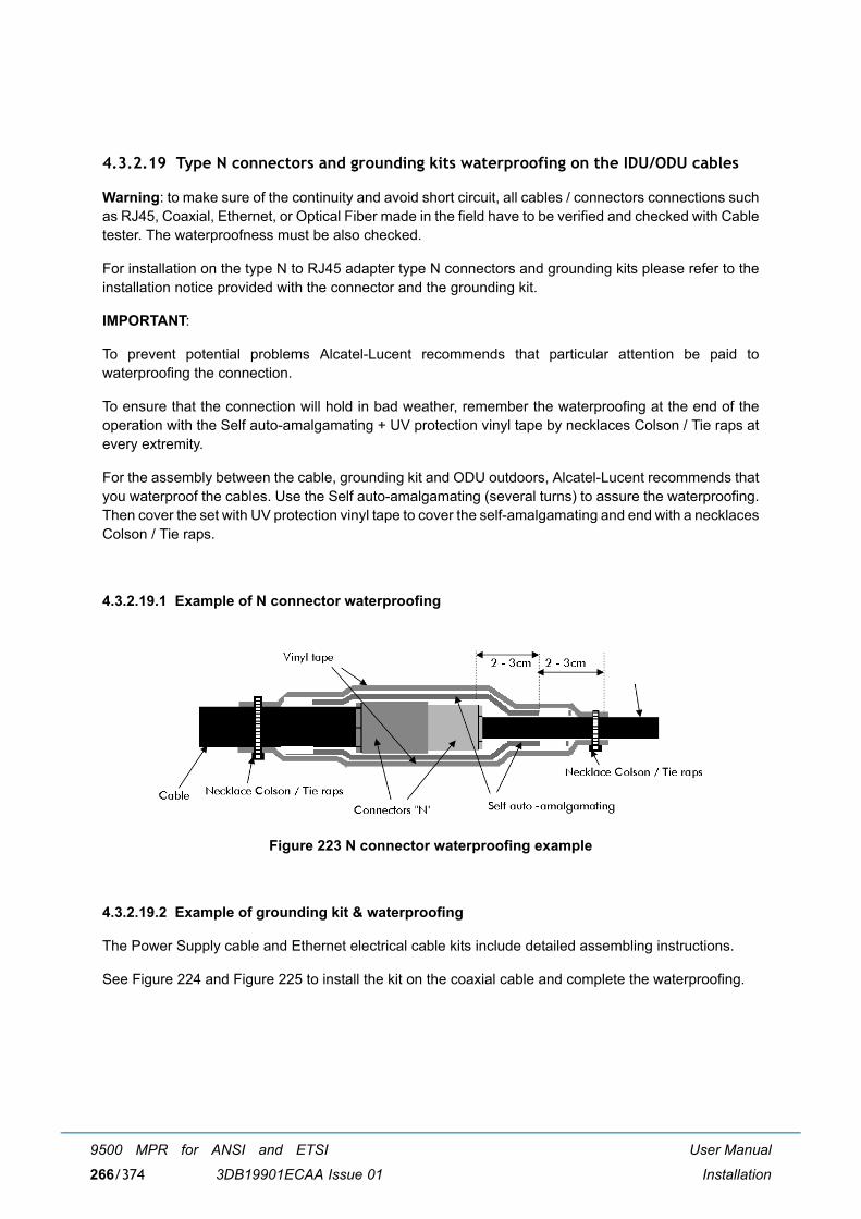
User Manual
Installation
9500 MPR for ANSI and ETSI
3DB19901ECAA Issue 01266/374
4.3.2.19 Type N connectors and grounding kits waterproofing on the IDU/ODU cables
Warning: to make sure of the continuity and avoid short circuit, all cables / connectors connections suchas RJ45, Coaxial, Ethernet, or Optical Fiber made in the field have to be verified and checked with Cabletester. The waterproofness must be also checked.
For installation on the type N to RJ45 adapter type N connectors and grounding kits please refer to theinstallation notice provided with the connector and the grounding kit.
IMPORTANT:
To prevent potential problems Alcatel-Lucent recommends that particular attention be paid towaterproofing the connection.
To ensure that the connection will hold in bad weather, remember the waterproofing at the end of theoperation with the Self auto-amalgamating + UV protection vinyl tape by necklaces Colson / Tie raps atevery extremity.
For the assembly between the cable, grounding kit and ODU outdoors, Alcatel-Lucent recommends thatyou waterproof the cables. Use the Self auto-amalgamating (several turns) to assure the waterproofing.Then cover the set with UV protection vinyl tape to cover the self-amalgamating and end with a necklacesColson / Tie raps.
4.3.2.19.1 Example of N connector waterproofing
Figure 223 N connector waterproofing example
4.3.2.19.2 Example of grounding kit & waterproofing
The Power Supply cable and Ethernet electrical cable kits include detailed assembling instructions.
See Figure 224 and Figure 225 to install the kit on the coaxial cable and complete the waterproofing.

User Manual
Installation
9500 MPR for ANSI and ETSI
3DB19901ECAA Issue 01 267/374
Figure 224 Example of realization
Figure 225 Detail of the waterproofing of the kit
Metal contact
Install grounding kit
Waterproofing with
Amalgamating + UV protection vinyl tape +
Tighten with allenkey 8 mm

User Manual
Installation
9500 MPR for ANSI and ETSI
3DB19901ECAA Issue 01268/374
4.3.3 MPT-MC installation
The MPT-MC installation section is divided in:
� Types of MPT-MC (par. 4.3.3.1 on page 269)
� MPT-MC operative information (par. 4.3.3.2 on page 270)
� How to change polarization in the MPT-MC (par. 4.3.3.3 on page 277)
� Types of pole mounting installation kits (par. 4.3.3.4 on page 279)
� Types of nose adapters (par. 4.3.3.5 on page 280)
� 1+0 MPT-MC installation (integrated antenna) - all frequencies (par. 4.3.3.6 on page 280)
� 1+0 MPT-MC installation (non integrated antenna) - all frequencies (par. 4.3.3.7 on page 283)
� To terminate the Ethernet cable (MPT-MC side) and to pull it up from indoor to MPT-MC (par. 4.3.3.8on page 285)
� Installing the �Flextwist� waveguide (not integrated antenna cases) (par. 4.3.3.9 on page 285)
� MPT-MC system grounding (par. 4.3.3.10 on page 285)
� Cable grounding (par. 4.3.3.11 on page 285)

User Manual
Installation
9500 MPR for ANSI and ETSI
3DB19901ECAA Issue 01 269/374
4.3.3.1 Types of MPT-MC
The MPT-MC consists of one or two cabinets including the Ethernet interface + modem + RF transceiver+ branching of a channel.
Two mechanical solutions are adopted:
[1] with embedded diplexer for cost optimisation, shown in Figure 226, where the branching (diplexer)is internal to the MPT-MC cabinet; this type of MPT-MC is identified by one Logistical Item only;
[2] with external diplexer: due to an high number of shifters the diplexer is external for the flexibility ofthe shifter customization, shown in Figure 227, where MPT-MC is composed by two independentunits: the BRANCHING assembly (containing the diplexer) and the RF TRANSCEIVER assembly(containing the RF section); each of this type of MPT-MC is identified by two Logistical Items, onefor the BRANCHING assembly and another for the RF TRANSCEIVER assembly. To read theBRANCHING assembly identification label it is necessary to separate the BRANCHING assemblyfrom the RF TRANSCEIVER assembly.
Figure 226 Views of MPT-MC with embedded diplexer
TRANSCEIVER + BRANCHING
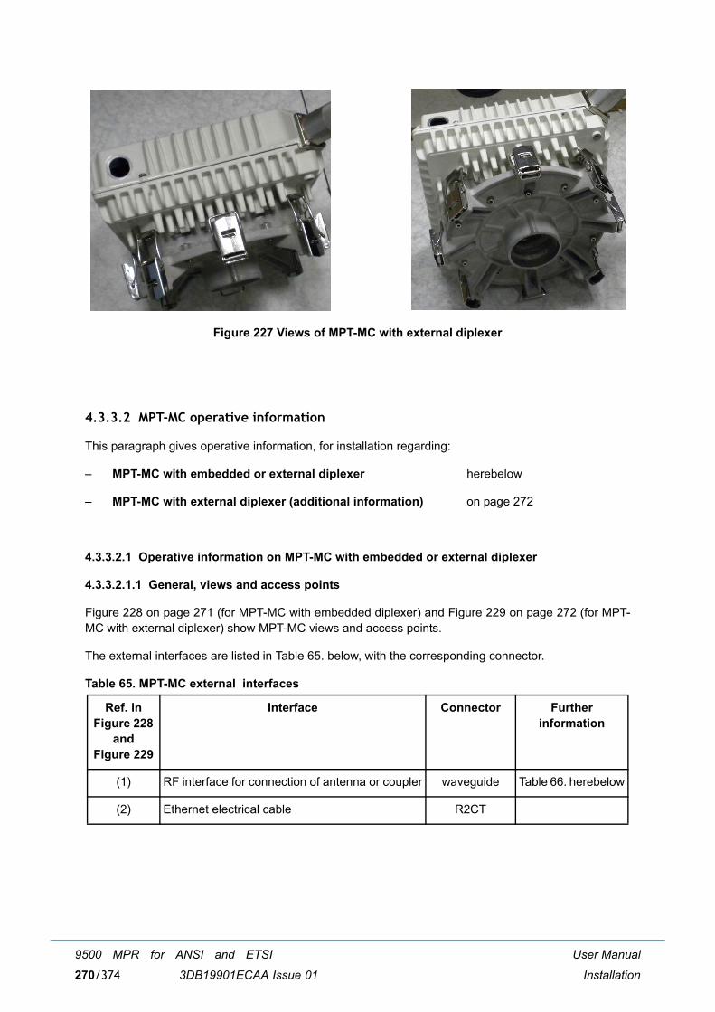
User Manual
Installation
9500 MPR for ANSI and ETSI
3DB19901ECAA Issue 01270/374
Figure 227 Views of MPT-MC with external diplexer
4.3.3.2 MPT-MC operative information
This paragraph gives operative information, for installation regarding:
� MPT-MC with embedded or external diplexer herebelow
� MPT-MC with external diplexer (additional information) on page 272
4.3.3.2.1 Operative information on MPT-MC with embedded or external diplexer
4.3.3.2.1.1 General, views and access points
Figure 228 on page 271 (for MPT-MC with embedded diplexer) and Figure 229 on page 272 (for MPT-MC with external diplexer) show MPT-MC views and access points.
The external interfaces are listed in Table 65. below, with the corresponding connector.
Table 65. MPT-MC external interfaces
Ref. in Figure 228
and Figure 229
Interface Connector Further information
(1) RF interface for connection of antenna or coupler waveguide Table 66. herebelow
(2) Ethernet electrical cable R2CT

User Manual
Installation
9500 MPR for ANSI and ETSI
3DB19901ECAA Issue 01 271/374
Table 66. RF interface
Figure 228 Views of MPT-MC with embedded diplexer
FREQUENCY GHz -> 6 7 8 11 13-15 18-26 38
Waveguide type -> WR137 WR112 WR112 WR75 WR62 WR42 WR28
(A) Locking hooks (4) to fix/unfix MPT-MC assembly to antenna or coupler
(1) RF interface for connection of antenna or coupler. Remove the plastic cover.
WARNING: A waterproofness tape is glued on the waveguide of the MPT-MC. It must never beremoved.
(1) (A)
(A)(A)
(A)
(2)

User Manual
Installation
9500 MPR for ANSI and ETSI
3DB19901ECAA Issue 01272/374
Figure 229 Views of MPT-MC with external diplexer
4.3.3.2.2 Additional operative information on MPT-MC with external diplexer
4.3.3.2.2.1 MPT-MC composition
As shown in Figure 230, the MPT-MC assembly is made up of two boxes, one for diplexer system(BRANCHING) and the other for the all other active functions (TRANSCEIVER) connected together toform the MPT-MC.
An O-RING present in the TRANSCEIVER box guarantees the MPT-MC assembly waterproofness.
Note: This is a conductive O-RING and must be left dry. Do not wet it with silicon grease (silicongrease must be used only on O-ring between MPT-MC and antenna).
(A) 4 locking hooks to fix/unfix branching assembly (diplexer) to transceiver
(B) 4 locking hooks to fix/unfix branching assembly (diplexer) to antenna or coupler
(1) RF interface for connection of antenna or coupler. Remove the plastic cover.
WARNING: A waterproofness tape is glued on the waveguide of the MPT-MC. It must never beremoved.
(1) (A)
(A)(A)
(A)
(B)(B)
(B)(B)(2)

User Manual
Installation
9500 MPR for ANSI and ETSI
3DB19901ECAA Issue 01 273/374
Figure 230 Composition of MPT-MC with external diplexer
WARNING 1: A waterproofness tape is glued on the waveguide of the MPT-MC. It must never be removed.
WARNING 2: This gasket must never be removed.
The TRANSCEIVER box performs all the functions, but does not include the diplexer system.
The BRANCHING box provides the interface between the pole mounting/antenna and theTRANSCEIVER.
The favorite solution foresees the possibility to change in field a spare part TRANSCEIVER withoutdisconnecting the BRANCHING box from the pole mounting/antenna. The TRANSCEIVER andBRANCHING boxes fixing and unfixing are obtained through the four levers.
BRANCHING TRANSCEIVER
WARNING 1 WARNING 2

User Manual
Installation
9500 MPR for ANSI and ETSI
3DB19901ECAA Issue 01274/374
4.3.3.2.2.2 TRANSCEIVER and BRANCHING boxes coupling
Figure 231 below shows the TRANSCEIVER and BRANCHING boxes coupling surfaces:
� (A) BRANCHING box label informative contentdescribed in Figure 233 on page 277
� (B) (HIGH FREQ) and (C) (LOW FREQ) RF interfaces on BRANCHING box
� (D) (TX) and (E) (RX) RF interfaces on TRANSCEIVER box
The TRANSCEIVER and BRANCHING boxes can be coupled in two alternative ways (180°-rotated withrespect to each other):
� BRANCHING box (B) (HIGH FREQ) coupled to TRANSCEIVER box�s (D) (TX)in this case the TX part of the transceiver uses the HIGH frequency range of the Shifter set by theCraft Terminal (see field D in Figure 233 on page 277); obviously the RX part of the transceiver usesthe corresponding LOW frequency range;
� BRANCHING box (C) (LOW FREQ) coupled to TRANSCEIVER box�s (D) (TX)in this case the TX part of the transceiver uses the LOW frequency range of the Shifter set by theCraft Terminal (see field D in Figure 233 on page 277); obviously the RX part of the transceiver usesthe corresponding HIGH frequency range.
Figure 231 MPT-MC TRANSCEIVER and BRANCHING boxes coupling surfaces
Note: There is only one possible way to couple the BRANCHING box and the TRANSCEIVER box:there is a mistake-proofing put by the factory on the TRANSCEIVER box, whose positiondepends on the type of transceiver (low or high band, as shown in Figure 231) to ensure thatthe association with the BRANCHING box is always the right one.
(A) (B)
(C)
(D)
(E)Hole Mistake-proofing

User Manual
Installation
9500 MPR for ANSI and ETSI
3DB19901ECAA Issue 01 275/374
4.3.3.2.3 Labels affixed on the MPT-MC
a) The label depicted in Figure 232 below is affixed externally to all types of MPT-MC and MPT-MCTRANSCEIVER boxes;
b) Only for MPT-MC with external diplexers, an additional label, depicted in Figure 233 on page 277,is placed on the branching assembly.

User Manual
Installation
9500 MPR for ANSI and ETSI
3DB19901ECAA Issue 01276/374
Figure 232 Label affixed on the MPT-MC and MPT-MC TRANSCEIVER box
SYMBOL OR WRITING MEANING
9500-MPR Equipment Acronym & Alcatel-Lucent Logo
CE European Community logo
! Not harmonized frequency logo
2002/96/EC WEEE (Waste Electrical andElectronic Equipment) Logo
-28 V / -58 V 1,6 A / 0,8 A Power supply range and current range
Logistical Item (shown numbers as examples) Logistical Item for Customer
A Logistical Item for Customer, bar code 128
Serial n° (shown numbers as examples) Factory Serial number
B Factory Serial number bar code 128
TX Frequency MHz (shown numbers as examples) Working frequency range
Shifter MHz (shown numbers as examples) Shifter
TX Sub-band (shown numbers as examples) TX Sub-band
Initial SW/ICS (shown numbers as examples) P/N and ICS of the software loaded in factory
PN/ICS (shown numbers as examples) Factory P/N + ICS
C Factory P/N + ICS bar code 128

User Manual
Installation
9500 MPR for ANSI and ETSI
3DB19901ECAA Issue 01 277/374
Figure 233 Label affixed inside the MPT-MC BRANCHING box
4.3.3.3 How to change polarization in the MPT-MC
4.3.3.3.1 Embedded diplexer MPT-MC
Note: The polarization must be changed to match the antenna polarization and the coupler nosewaveguide.
WARNING: A waterproofness tape is glued on the waveguide of the MPT-MC. It must never be removed.
SYMBOL OR WRITING MEANING
ALU LOGO Alcatel-Lucent Logo
9500 MPR Equipment Acronym
C E European Community logo
0682 CETECOM Number
! Not Harmonized Frequency Logo
WEEE LOGO WEEE Logo
P/N / ICS 3DBXXXXXAAAA 01 Part Number + ICS
LOGISTICAL ITEM 3DBXXXXXAAXX Logistical Item
S.N. GA081528595 Serial number
A P/N + ICS Bar Code Alpha 128
B Logistical Item Bar Code Alpha 128
C Serial Number Bar Code Alpha 128
Shifter MHzTX
F min MHzF max MHz
Frequency Denomination

User Manual
Installation
9500 MPR for ANSI and ETSI
3DB19901ECAA Issue 01278/374
1 2
3
Remove the plastic protection cover fromthe MPT-MC.
Change the polarization of the MPT-MC, ifrequired (default: vertical polarization).
To rotate the polarization use the Allenwrench.
Horizontal polarization.
Protection cover
Unscrew the 2 screws
Polarization
Polarization

User Manual
Installation
9500 MPR for ANSI and ETSI
3DB19901ECAA Issue 01 279/374
4.3.3.3.2 External diplexer MPT-MC
These MPT-MC have fixed polarization (vertical polarization). To change the polarization it is necessaryto change the antenna polarization and to install the MPT-MC 90° rotated.
4.3.3.4 Types of pole mounting installation kits
Refer to paragraph 4.3.2.5 on page 216.
1 2Example of vertical polarization (left offset). Example of horizontal polarization (left offset).
3 4Example of vertical polarization (rightoffset).
Example of horizontal polarization (right offset).

User Manual
Installation
9500 MPR for ANSI and ETSI
3DB19901ECAA Issue 01280/374
4.3.3.5 Types of nose adapters
Refer to paragraph 4.3.2.6 on page 218.
4.3.3.6 1+0 MPT-MC installation (integrated antenna) - all frequencies
[1] Check/Set the coupling between the TRANSCEIVER and BRANCHING boxes (only for MPT-MCwith external diplexer).
[2] Install the Antenna and Pole Mounting.This pole mounting is delivered as �pole mounting�, �antenna�, and frequency-specific �noseadapter� already assembled. The integrated antenna is mounted on the pole front.Antenna and pole mounting must be installed in accordance with the manufacturer�s instructions.
[3] Check or change the polarization on the Antenna nose.To change the polarization, follow the instructions supplied with each antenna. Figure 234 shows anexample.
Note: The antennas are normally supplied with vertical polarization.
Figure 234 Example of antenna polarization change (�1+0� MPT-MC integrated antenna)
[4] Install the MPT-MC on the Antenna nose adapter.

User Manual
Installation
9500 MPR for ANSI and ETSI
3DB19901ECAA Issue 01 281/374
Note: Silicone grease must be put on the nose adapter O-ring when indicated in themanufacturer�s installation instructions. If grease for O-ring is not mentioned, it must beavoided.
Figure 235 Putting silicone grease on O-ring before MPT-MC insertion
1) Grasp the MPT-MC module by the handle.
2) Open the four looking hooks (1) arranged on the four walls of the MPT-MC unit.
3) For 7-8 GHz MPT-MC only rotate the MPT-MC depending on the horizontal or verticalpolarization, and slide it on the nose adapter.
4) Secure the MPT-MC module through the four hooks (1) on the relative brackets (2).
Figure 236 MPT-MC 1+0 installation for integrated antenna (internal diplexer)
Note: For 6 GHz and 11-38 GHz MPT-MC remember to set first the correct polarization.
Apply silicone greasewhen necessary
(1) Hook
(2) Bracket

User Manual
Installation
9500 MPR for ANSI and ETSI
3DB19901ECAA Issue 01282/374
Figure 237 MPT-MC 1+0 installation for integrated antenna (external diplexer: vertical polarization)
Figure 238 MPT-MC 1+0 installation for integrated antenna (external diplexer: horizontal polarization)
REMINDER: The MPT-MC/antenna assembly requires no additional seal on the SHF flanges; thetwo ends are smooth. The O-ring seal around the male �nose� provides sealing.
[5] Ground the MPT-MC system.
[6] Pre-point the antenna.
(1) Hook
(2) Bracket
(1) Hook
(2) Bracket

User Manual
Installation
9500 MPR for ANSI and ETSI
3DB19901ECAA Issue 01 283/374
[7] Affix the EMF stickers.
4.3.3.7 1+0 MPT-MC installation (non integrated antenna) - all frequencies
[1] Check/Set the coupling between the TRANSCEIVER and BRANCHING boxes (only for MPT-MCwith external diplexer).
[2] Install the Nose Adapter on the �Pole Mounting for Remote ODU�.
[3] Install the �Pole Mounting for Remote ODU�.Pole mounting must be installed in accordance with the manufacturer�s instructions.In case of missing instructions, fix the U-bolts with 34 N x m tightening torque.
Note: The pole mounting can be installed on the Right or Left hand side of the pole dependingon the azimuth and on the configuration of the tower.
Figure 239 "Pole Mounting for Remote ODU" installation
[4] Install the MPT-MC.
Note: Silicone grease must be put on the nose adapter O-ring when indicated in themanufacturer�s installation instructions. If grease for O-ring is not mentioned, it must beavoided.
Figure 240 Putting silicone grease on O-ring before MPT-MC insertion
Apply silicone greasewhen necessary

User Manual
Installation
9500 MPR for ANSI and ETSI
3DB19901ECAA Issue 01284/374
1) Grasp the MPT-MC module by the handle. Open the four looking hooks arranged on the fourwalls of the MPT-MC unit.
2) Position the Pole mounting support on the pole side as shown in the plant documentation.
3) Position the MPT-MC and slide it on the nose adapter.
4) Secure the MPT-MC module through the four hooks onto the relative brackets.
Figure 241 MPT-MC 1+0 installation for not integrated antenna (with pole mounting P/N 3DB10137AAXX)
[5] Install the external Antenna with its own Pole Mounting.The installation of the antenna and of its own pole mounting, as well as the antenna polarizationcheck/change, must be done in accordance with the manufacturer�s instructions.
[6] Connect the antenna side (flange) of the Pole Mounting�s nose adapter to the external antenna, bymeans of the �Flextwist� waveguide. (Refer to paragraph 4.3.2.16).
[7] Ground the MPT-MC system.
[8] Pre-point the antenna.
[9] Affix the EMF stickers.

User Manual
Installation
9500 MPR for ANSI and ETSI
3DB19901ECAA Issue 01 285/374
4.3.3.8 To terminate the Ethernet cable (MPT-MC side) and to pull it up from indoor to MPT-MC
Only one cable interconnects the MPT-MC with the Power Injector. Refer to paragraph 4.3.2.14.1 on page254.
4.3.3.9 Installing the �Flextwist� waveguide (not integrated antenna cases)
Refer to paragraph 4.3.2.16 on page 262.
4.3.3.10 MPT-MC system grounding
Refer to paragraph 4.3.2.17 on page 264.
4.3.3.11 Cable grounding
Refer to paragraph 4.3.2.18 on page 265.
4.3.3.12 Grounding kits waterproofing on the IDU/ODU cables
Refer to paragraph 4.3.2.19 on page 266.
4.3.4 Power injector
a) Elevated Operating Ambient - If installed in a closed or multi-unit rack assembly, the operatingambient temperature of the rack environment may be greater than room ambient. Therefore,consideration should be given to installing the equipment in an environment compatible with themaximum ambient temperature (Tma) specified by the manufacturer.
b) Reduced Air Flow - Installation of the equipment in a rack should be such that the amount of airflow required for safe operation of the equipment is not compromised.
c) Mechanical Loading - Mounting of the equipment in the rack should be such that a hazardouscondition is not achieved due to uneven mechanical loading.
d) Circuit Overloading - Consideration should be given to the connection of the equipment to thesupply circuit and the effect that overloading of the circuits might have on over current protection andsupply wiring. Appropriate consideration of equipment nameplate ratings should be used whenaddressing this concern.
e) Reliable Earthing - Reliable earthing of rack-mounted equipment should be maintained. Particular attention should be given to supply connections other than direct connections to thebranch circuit (e.g. use of power strips).

User Manual
Installation
9500 MPR for ANSI and ETSI
3DB19901ECAA Issue 01286/374
4.3.4.1 Power injector box
The installation in 19� rack is shown in the Figure 242.
Note: Disconnect all power supply cords before servicing.
The Power Injector box must be first installed on the bracket (3DB77008ACXX) by using the screwsprovided with the bracket, and then the assembly must be installed on the rack.
Figure 242 Power injector box + bracket 3DB77008ACXX
For the installation in 21� rack the 21� Adapter kit (3CC50065AAAA) must be added to each 19� installationconfiguration.

User Manual
Installation
9500 MPR for ANSI and ETSI
3DB19901ECAA Issue 01 287/374
4.3.4.1.1 Power injector box grounding
The assembly must be grounded by using the ground screw present on the bracket, as shown in Figure243
The section cable (wire) is 6 mm² (9AWG) (Yellow/Green).
Figure 243 Grounding
4.3.4.1.2 Power supply cable
Figure 244 Power supply connector
Note: The power source "office power" is isolated from AC power main feeds.
A 2-wire power cable (2x1 mm2 - AWG17) is supplied (1AC007800068).
Note: Power cable gauge smaller than 2x1 mm2 (AWG 17) is not allowed for proper operation of thePower Injector box.
The blue wire must be connected to -48 Vdc (live); the black wire to + (Return).
The cable must be screwed to the Power Injector box and to the battery.
Note: The Power supply must be connected to a fuse or a breaker on a customer power distributionbox. The recommended value is 3 Amps for one ODU and 6 Amps for two ODUs.
Battery Return-48 Vdc Battery

User Manual
Installation
9500 MPR for ANSI and ETSI
3DB19901ECAA Issue 01288/374
4.3.4.2 Power injector card
The Power Injector card is installed inside the 7705 SAR.
Figure 245 Power Injector card
4.3.4.2.1 Grounding
The subrack must be grounded using the ground screw present on the front panel of the bracket on theright side.
The section cable (wire) to use must be a 6 mm² (9AWG) (Yellow/Green).
The subrack-mounting item adds a good electrical connection to rack ground.

User Manual
Installation
9500 MPR for ANSI and ETSI
3DB19901ECAA Issue 01 289/374
4.3.5 Installation items
This section includes:
� Indoor accessories for MPT-HC V2/MPT-XP/9558HC (par. 4.3.5.1 on page 289)
� Accessories and cables for MPT-HC V2/MPT-XP/9558HC connections (par. 4.3.5.2 on page 289)
� MPR-E Accessories and cables for MPT-MC connections (par. 4.3.5.3 on page 291)
� Nose Adapter for MPT-HC V2/MPT-MC,MPT-XP, and 9558HC (par. 4.3.5.4 on page 292)
� Flextwists and N cable for MPT-HC V2/MPT-MC,MPT-XP, and 9558HC (par. 4.3.5.5 on page 293)
� Ethernet electrical cables (par. 4.3.5.6 on page 293)
4.3.5.1 Indoor accessories for MPT-HC V2/MPT-XP/9558HC
Table 67. Indoor accessories for MPT-HC V2/MPT-XP/9558HC
4.3.5.2 Accessories and cables for MPT-HC V2/MPT-XP/9558HC connections
Table 68. Accessories and cables for MPT-HC V2/MPT-XP/9558HC connections
3CC52159AAXX Pigtail These accessories must be used toconnect the power coaxial cable ofMPT-HC V2/MPT-XP/9558HC to thebattery
1AB251350001 Low Pass Filter
3CC50030AAAA Lightning Arrestor
3DB18205AAAA QMA (male)-N (Female) RF cable
3CC50074ABAA Support kit for 4 cord N/QMA MPR IDU
1AB357780003 QMA 90° connector for coax. cable (diam.=6.85 mm)
3CC52188AAXX N-to-Ethernet pair pigtail (N female-Free wires) for the power supply cable (1 m)
1AB074610027 RJ45 connector (boot included). To be terminated on the 1 m Adapter cord forIndoor connection or Outdoor connection.
1AB150990002 R2CT connector. To be terminated on the 1 m Adapter cord for Outdoorconnection.
1AD160490001 Tool for HIROSE RJ45 IDU-ODU cable assembling
1AC016760006 IDU-ODU Cat5e Ethernet cable (cable to be used for PFoE, with RJ45 andR2CT connectors)
1AD040130004 Grounding kit for Cat5e cable

User Manual
Installation
9500 MPR for ANSI and ETSI
3DB19901ECAA Issue 01290/374
1AC001060084 Outdoor Grounding cable 16 mm2
1AC001100022 Coax cable 50 ohm (diam.=10.3 mm) for L>200 m
1AB095530023 N Conn. male straight 50 ohm for coax. cable (diam.=10.3 mm)
1AB128500002 Grounding kit for coax. cable (diam.=10.3 mm)
1AC041350001 Coax. cable 50 ohm (diam.=6.85 mm) for L<200 m
1AB095530036 N Conn. male straight 50 ohm for coax. cable (diam.=6.85 mm)
1AD040130004 Grounding kit for coax. cable (diam.=6.85 mm)
3CC52170ANXX or3CC52170BN
LC/Q-XCO to LC Fiber cord (L = 25 m for MPR-e IDU-ODU connection)
3CC52170AMXX or3CC52170BM
LC/Q-XCO to LC Fiber cord (L = 50 m for MPR-e IDU-ODU connection)
3CC52170AAXX or3CC52170BA
LC/Q-XCO to LC Fiber cord (L = 80 m for MPR-e IDU-ODU connection)
3CC52170ABXX or3CC52170BB
LC/Q-XCO to LC Fiber cord (L = 100 m for MPR-e IDU-ODU connection)
3CC52170ACXX or3CC52170BC
LC/Q-XCO to LC Fiber cord (L = 120 m for MPR-e IDU-ODU connection)
3CC52170ADXX or3CC52170BD
LC/Q-XCO to LC Fiber cord (L = 140 m for MPR-e IDU-ODU connection)
3CC52170AEXX or3CC52170BE
LC/Q-XCO to LC Fiber cord (L = 160 m for MPR-e IDU-ODU connection)
3CC52170AFXX or3CC52170BF
LC/Q-XCO to LC Fiber cord (L = 180 m for MPR-e IDU-ODU connection)
3CC52170AGXX or3CC52170BG
LC/Q-XCO to LC Fiber cord (L = 200 m for MPR-e IDU-ODU connection)
3CC52170AHXX or3CC52170BH
LC/Q-XCO to LC Fiber cord (L = 220 m for MPR-e IDU-ODU connection)
3CC52170AIXX or3CC52170BY
LC/Q-XCO to LC Fiber cord (L = 250 m for MPR-e IDU-ODU connection)
3CC52170ALXX or3CC52170BL
LC/Q-XCO to LC Fiber cord (L = 300 m for MPR-e IDU-ODU connection)
3CC50097AAXX Cable overlength box (wall and pipe mounting only)
3CC52186AAXX XPIC cable cat7 (L = 1 m)

User Manual
Installation
9500 MPR for ANSI and ETSI
3DB19901ECAA Issue 01 291/374
4.3.5.3 MPR-E Accessories and cables for MPT-MC connections
Table 69. MPR-E: Accessories and cables for MPT-MC connections
3CC52186ABXX XPIC cable cat7 (L = 2.5 m)
3CC52186ACXX XPIC cable cat7 (L = 8 m)
3CC52169AAXX or3CC52169BA
RPS LC-LC optical jumper preassembled with Q-XCO (L = 1 m)
3CC52169ABXX or3CC52169BB
RPS LC-LC optical jumper preassembled with Q-XCO (L = 10 m for spacediversity)
3CC52169ACXX or3CC52169BC
RPS LC-LC optical jumper preassembled with Q-XCO (L = 20 m for spacediversity)
3CC52189AAXX or3CC52189BA
RPS Q-XCO to Q-XCO cable (L = 1 m)
3CC52189ABXX or3CC52189BB
RPS Q-XCO to Q-XCO cable (L = 10 m)
3CC52189ACXX or3CC52189BC
RPS Q-XCO to Q-XCO cable (L = 20 m)
3CC50098AAXX MPR-MPT tool bag (special tools)
3CC50099AAXX Standard tool bag
3CC50173AAXX MPT Power Unit (includes rack mounting bracket)
3CC50174AAXX MPT Extended Power Unit (includes rack mounting bracket)
1AC016760006 IDU-ODU Ethernet cable Cat5e shield 80% for outdoor environment
1AB074610027 RJ45 connector (cable diam <=7mm) (boot included)
1AD160490001 Tool for HIROSE RJ45 IDU-ODU cable assembling
1AB150990002 Kit plug R2CT
1AD040130004 Grounding kit for RJ45 Ethernet electrical cable
1AC001060084 Outdoor Grounding cable 16 mm2
3CC50098AAXX MPR-MPT tool bag (special tools)
3CC50099AAXX Standard tool bag
3CC50174AAXX MPT Extended Power Unit

User Manual
Installation
9500 MPR for ANSI and ETSI
3DB19901ECAA Issue 01292/374
4.3.5.4 Nose Adapter for MPT-HC V2/MPT-MC,MPT-XP, and 9558HC
Table 70. Nose Adapter for MPT-HC V2/MPT-MC,MPT-XP, and 9558HC
3DB01460ABXX 5.8 GHz Unlicensed/6 GHz Nose Adapter with waveguide output (for NotIntegrated Antenna)
3CC50172AAXX 5.8GHz Unlicensed/6GHz Nose Adapter with N output (for Not IntegratedAntenna)
3DB10135AAXX 7/8 GHz Nose Adapter (for Not Integrated Antenna)
3CC50125AAXX 11 GHz Nose Adapter (for Not Integrated Antenna)
3CC50179AAXX1 13 GHz Nose Adapter (for Not Integrated Antenna)
3CC50177AAXX 15 GHz Nose Adapter (for Not Integrated Antenna)

User Manual
Installation
9500 MPR for ANSI and ETSI
3DB19901ECAA Issue 01 293/374
4.3.5.5 Flextwists and N cable for MPT-HC V2/MPT-MC,MPT-XP, and 9558HC
Table 71. Flextwists and N cable for MPT-HC V2/MPT-MC,MPT-XP, and 9558HC
4.3.5.6 Ethernet electrical cables
Table 72. Ethernet electrical cables
3CC50178AAXX 18/23/25 Nose Adapter (for Not Integrated Antenna)
3DB02082AAXX 28/38 Nose Adapter (for Not Integrated Antenna)
1. MPR-E
1AF02951ABAA 5.8 GHz Unlicensed/6 GHz flextwist L = 1m (PDR-UDR)
1AF11977AAAA 7/8 GHz flextwist WR112 L = 1m (PDR84/UBR84)
3CC05751ACAA 11 GHz flextwist L = 0.6m
3CC05751ACAA1
1. MPR-E
13 GHz flextwist L = 0.6m
3CC05750ACAA 15 GHz flextwist L = 0.6m
3CC05749ACAA 18/23/25 GHz flextwist L = 0.6m
3DB00682AAXX 28/38 GHz flextwist L = 0.6m
3CC52198ABXX N-N coaxial cable L=2m
3CC52198AAXX N-N coaxial cable L=1m
3CC52141ABAA RJ45-RJ45 Eth. CAT5E shielded straight cable 5 m
3CC52141ACAA RJ45-RJ45 Eth. CAT5E shielded straight cable 15 m

User Manual
Installation
9500 MPR for ANSI and ETSI
3DB19901ECAA Issue 01294/374
4.3.6 Antenna alignment
This section includes:
� Preparation (see par. 4.3.6.1 on page 294)� Signal measurement (see par. 4.3.6.2 on page 294)� Aligning the antenna (see par. 4.3.6.3 on page 297)� Main beams and side lobes (see par. 4.3.6.4 on page 302)
4.3.6.1 Preparation
Warning: to make sure of the continuity and avoid short circuit, all cables / connectors connections suchas RJ45, Coaxial, Ethernet, or Optical Fiber made in the field have to be verified and checked with Cabletester. The waterproofness must be also checked.
Before aligning antennas ensure:
� The ODUs are powered up at both ends of the link. � Transmit and receive frequencies are correctly set. � Transmit powers are correctly set and transmit mute is turned off.
Note: If frequency and/or power settings are not correct for the application, interference may be caused to other links in the same geographical area.
4.3.6.2 Signal measurement
Two receive signal-strength indicators are provided to assist antenna alignment, RSL in the WebEMLscreen, and the RSSI voltage at LEMO connector on the MPT-HC V2/MPT-MC/MPT-XP/9558HC. Referto:
� Using RSL Data (see par. 4.3.6.2.1 on page 294)� Using the RSSI Voltage at the MPT-HC V2/MPT-MC/MPT-XP/9558HC (see par. 4.3.6.2.2 on page
295)� RSL Measurement Guidelines (see par. 4.3.6.2.2.1 on page 296)
4.3.6.2.1 Using RSL data
As CT is accessed via connection to the GEthernet Generic Device, a separate means of communicationsuch as two-way radio or cell phone is required between the WebEML operator and the person at theantenna.
To align using RSL:
1) Monitor RSL in the WebEML screen. 2) Set antenna alignment for maximum RSL. 3) Repeat for the far end of the link. 4) Compare actual RSLs with the expected RSLs from the link installation datapack. RSL
measurement accuracies:
a) ± 2 dB for levels -40 to -70 dBm, over a temperature range of 0 to +35°C.
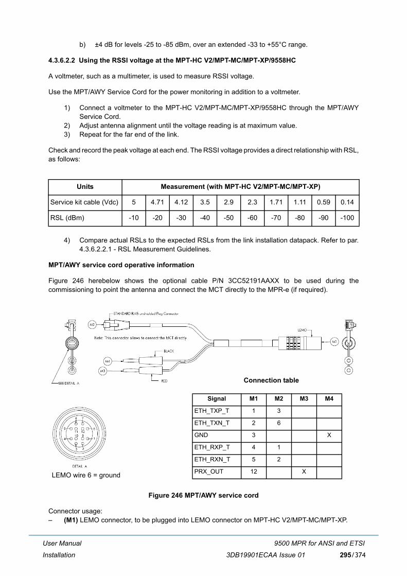
User Manual
Installation
9500 MPR for ANSI and ETSI
3DB19901ECAA Issue 01 295/374
b) ±4 dB for levels -25 to -85 dBm, over an extended -33 to +55°C range.
4.3.6.2.2 Using the RSSI voltage at the MPT-HC V2/MPT-MC/MPT-XP/9558HC
A voltmeter, such as a multimeter, is used to measure RSSI voltage.
Use the MPT/AWY Service Cord for the power monitoring in addition to a voltmeter.
1) Connect a voltmeter to the MPT-HC V2/MPT-MC/MPT-XP/9558HC through the MPT/AWYService Cord.
2) Adjust antenna alignment until the voltage reading is at maximum value. 3) Repeat for the far end of the link.
Check and record the peak voltage at each end. The RSSI voltage provides a direct relationship with RSL,as follows:
4) Compare actual RSLs to the expected RSLs from the link installation datapack. Refer to par.4.3.6.2.2.1 - RSL Measurement Guidelines.
MPT/AWY service cord operative information
Figure 246 herebelow shows the optional cable P/N 3CC52191AAXX to be used during thecommissioning to point the antenna and connect the MCT directly to the MPR-e (if required).
Figure 246 MPT/AWY service cord
Connector usage:� (M1) LEMO connector, to be plugged into LEMO connector on MPT-HC V2/MPT-MC/MPT-XP.
Units Measurement (with MPT-HC V2/MPT-MC/MPT-XP)
Service kit cable (Vdc) 5 4.71 4.12 3.5 2.9 2.3 1.71 1.11 0.59 0.14
RSL (dBm) -10 -20 -30 -40 -50 -60 -70 -80 -90 -100
LEMO wire 6 = ground
Connection table
Signal M1 M2 M3 M4
ETH_TXP_T 1 3
ETH_TXN_T 2 6
GND 3 X
ETH_RXP_T 4 1
ETH_RXN_T 5 2
PRX_OUT 12 X

User Manual
Installation
9500 MPR for ANSI and ETSI
3DB19901ECAA Issue 01296/374
� banana plugs (M3) and (M4): output is a 0 to +5V DC voltage proportional to the radio Rx field. Duringequipment line�up, through a multi�meter it is possible to easily point the antenna until the measuredvoltage is the maximum, corresponding to the maximum radio Rx field.
� (M2) RJ45 connector, to connect the WebEML directly to the MPT.
4.3.6.2.2.1 RSL measurement guidelines
RSSI/RSL accuracy
When checking RSSI/RSL against the predicted link values ensure appropriate allowances are made forTx power-setting accuracy, path-loss calculation accuracy, and RSSI/RSL measurement accuracy.
� For a worst-case the overall accuracy is the sum of the individual accuracy limits, which for a linkwould be ±4 dB of the predicted value (±2 dB for transmit, ±2 dB for receive, 0 to 35°C), aside fromthe path-loss calculation accuracy, which should be within limits of ±3 dB.
� Typically, where the measured RSSI/RSL is more than 4 dB lower than the expected receive levelyou should check the path survey results, path calculations and antenna alignment.
Note: When checking RSSI/RSL ensure the measurement is made under normal, unfaded and interference-free path conditions.
� A discrepancy of 20 dB or greater between the measured and calculated RSSI/ RSLs suggests anantenna is aligned on a side lobe, or there is a polarization mismatch.

User Manual
Installation
9500 MPR for ANSI and ETSI
3DB19901ECAA Issue 01 297/374
4.3.6.3 Aligning the antenna
Antenna alignment involves adjusting the direction of each antenna until the received signal strengthreaches its maximum level at each end of the link.Fine adjustment for azimuth (horizontal angle) andelevation (vertical angle) is built into each antenna mount.
Adjustment procedures will be provided with each antenna.If the horizontal adjuster does not providesufficient range to locate the main beam, the antenna mounting brackets will need to be loosened andthe antenna swiveled on its pole mount to locate the beam.
Before doing this ensure the horizontal adjuster is set for mid-travel.
Some mounts for larger antennas have a separately clamped swivel base to allow the loosened antennato swivel on it without fear of slippage down the pole. Where such a mount is not provided a temporaryswivel clamp can often be provided using a pair of pipe brackets bolted together immediately below theantenna mount.
Note: Ensure antennas are aligned on the main beam, and not a side lobe.
For guidance, refer to the sections Locating the Main Beam (see par. 4.3.6.4.1 on page 302)and Tracking Path Error (see par. 4.3.6.4.2 on page 303).
Ensure ATPC is turned off during the alignment procedure.
4.3.6.3.1 Standard alignment procedure
To align an antenna:
1) Loosen the azimuth adjuster on the antenna mount (horizontal angle) and adjust azimuthposition for maximum signal strength. Ensure antennas are aligned on the main beam, and nota side lobe.
2) Tighten the azimuth securing mechanism. Ensure signal strength does not drop as it istightened.
3) Loosen the elevation adjuster (vertical angle) and adjust for maximum signal strength. Ensureantennas are aligned on the main beam, and not a side lobe.
4) Tighten the elevation securing mechanism. Ensure signal strength does not drop as it istightened. The terminal is now aligned and ready to carry operational traffic.
5) Record RSL and/or RSSI voltage in the commissioning log.

User Manual
Installation
9500 MPR for ANSI and ETSI
3DB19901ECAA Issue 01298/374
4.3.6.3.2 Additional procedure for CCDP XPIC links with MPT-HC V2/MPT-XP
Note: Procedures are provided for the alignment of dual polarized antennas, and for protected XPIClinks.
For CCDP (Co-channel Dual Polarized) XPIC (Cross Polarized Interference Cancellation) links it isimportant that antenna feeds are correctly aligned to achieve optimum XPIC performance.
While a dual-feed antenna may be specified with a cross polarization discrimination of 30 dB, unless theantenna-to-antenna alignment over a link is correct, the effective discrimination can be significantly less.
� The horizontal-to-vertical receive signal discrimination for satisfactory XPIC operation must not beless than 25 dB, and where possible should be set for optimum discrimination using this procedure.
� High performance shielded antennas typically exhibit 30 dB cross polarization discriminationwhereas 40 dB is typical for purpose-designed, high polarization discrimination antennas.
� The received-signal V and H discrimination can be checked using the Radio Synthesis tab-panelof the MPT-HC V2/MPT-XP/9558HC, as shown in Figure 247
Figure 247 XPD measurement
The cross pole discrimination measures the V and H signal discrimination in dB at the input to theMPT-HC V2/MPT-XP/9558HC (from the antenna feeds). The improvement in signal discriminationprovided by the XPIC function is in addition to this measurement.
Note: This alignment procedure is intended for dual-polarized antennas, but is also generallyapplicable to installations using separate antennas for V and H planes.
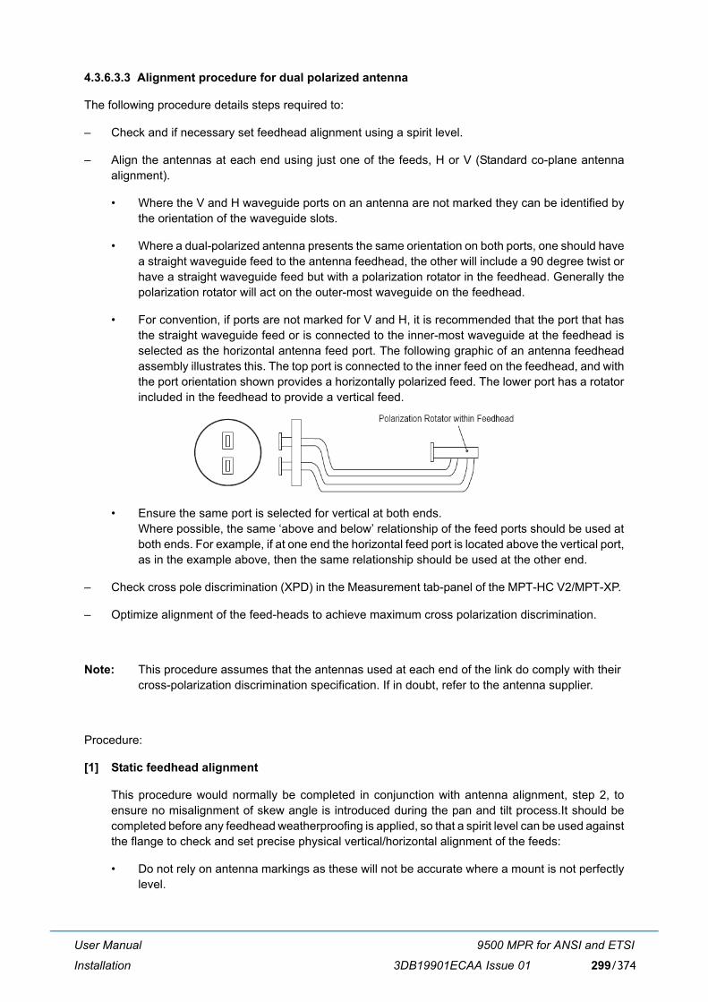
User Manual
Installation
9500 MPR for ANSI and ETSI
3DB19901ECAA Issue 01 299/374
4.3.6.3.3 Alignment procedure for dual polarized antenna
The following procedure details steps required to:
� Check and if necessary set feedhead alignment using a spirit level.
� Align the antennas at each end using just one of the feeds, H or V (Standard co-plane antennaalignment).
� Where the V and H waveguide ports on an antenna are not marked they can be identified bythe orientation of the waveguide slots.
� Where a dual-polarized antenna presents the same orientation on both ports, one should havea straight waveguide feed to the antenna feedhead, the other will include a 90 degree twist orhave a straight waveguide feed but with a polarization rotator in the feedhead. Generally thepolarization rotator will act on the outer-most waveguide on the feedhead.
� For convention, if ports are not marked for V and H, it is recommended that the port that hasthe straight waveguide feed or is connected to the inner-most waveguide at the feedhead isselected as the horizontal antenna feed port. The following graphic of an antenna feedheadassembly illustrates this. The top port is connected to the inner feed on the feedhead, and withthe port orientation shown provides a horizontally polarized feed. The lower port has a rotatorincluded in the feedhead to provide a vertical feed.
� Ensure the same port is selected for vertical at both ends. Where possible, the same �above and below� relationship of the feed ports should be used atboth ends. For example, if at one end the horizontal feed port is located above the vertical port,as in the example above, then the same relationship should be used at the other end.
� Check cross pole discrimination (XPD) in the Measurement tab-panel of the MPT-HC V2/MPT-XP.
� Optimize alignment of the feed-heads to achieve maximum cross polarization discrimination.
Note: This procedure assumes that the antennas used at each end of the link do comply with their cross-polarization discrimination specification. If in doubt, refer to the antenna supplier.
Procedure:
[1] Static feedhead alignment
This procedure would normally be completed in conjunction with antenna alignment, step 2, toensure no misalignment of skew angle is introduced during the pan and tilt process.It should becompleted before any feedhead weatherproofing is applied, so that a spirit level can be used againstthe flange to check and set precise physical vertical/horizontal alignment of the feeds:
� Do not rely on antenna markings as these will not be accurate where a mount is not perfectlylevel.

User Manual
Installation
9500 MPR for ANSI and ETSI
3DB19901ECAA Issue 01300/374
� Set the spirit level against the flange of the feedhead. Take care that only the flange of thefeedhead is measured, so that no error is introduced by any minor misalignment of the matingflexible waveguide flange. See Figure 248
Figure 248 Checking feedhead flange with a spirit level
� If not exactly vertical or horizontal, adjust the feedhead skew angle (rotate the feedhead) untilcorrect (spirit level bubble is precisely centered). For a typical feedhead check both flanges forlevel, using an end point half way between the level points of the two flanges should there beany discrepancy between the two.
[2] Align antennas
Align the antennas at both ends using the standard (co-plane) alignment procedure, but using just oneof the feeds, V or H. Refer to Standard Alignment Procedure (see par. 4.3.6.3.1 on page 297).
If major adjustment to the pointing of the antenna is made during this process, recheck the feedhead skewangle.
When correct, proceed to step 3.
[3] Check operation and end-end feedhead alignment
Power-up both V and H links and check they are operating normally and are alarm-free. Use theMeasurement tab-panel of the MPT-HC V2/MPT-XP to check that:
� Tx power measurements are within 1 dB (typically). If not check Tx power settings.
� RSL measurements are within 2 dB. See Using RSL Data (see par. 4.3.6.2.1 on page 294) forguidance on measurement accuracy.
� Links are operating error-free.

User Manual
Installation
9500 MPR for ANSI and ETSI
3DB19901ECAA Issue 01 301/374
Note: Where there is potential for interference from other links in the same geographical area, check by turning the far end transmitter(s) off and measuring the local end RSL on both V and H feeds.
[4] Use the cross pole discrimination (XPD) measurement provided in the Measurement tab-panel ofthe MPT-HC V2/MPT-XP to measure the actual V and H signal discrimination from each antenna. � Where measured XPDs are better than 25 dB no further adjustment is needed � Where less than 25 dB proceed to the next step.
Caution. It is possible for a spurious XPD figure of about 50 dB to appear in instances wherethere is major mis-alignment. Note that the raw XPD should never read higher than the XPDspecification of the antennas, which for most high performance dual-pol antennas will bebetween 30 dB to 35 dB.
Note: The alignment procedures listed under steps 1 and 2 should result in a discrimination of betterthan 25 dB, as measured in the Measurement tab-panel of the MPT-HC V2/MPT-XP, which iscomfortably within the operating limits of XPIC. However, for best results and greater operatingmargins during fading, feedhead alignment should be optimized using the following procedure.
[5] Optimize end-end feedhead alignment
This procedure corrects for any minor rotational alignment between antennas at each end.One antenna is the reference antenna and its feed-head assembly is not adjusted during thisprocedure.
Note: Only check/adjust skew angles on one antenna. If both antennas are adjusted and re-adjustedthere is potential for progressive misalignment to occur. Select one antenna as the referenceantenna. On long hops and where fading is prevalent there is potential for the V and H planepaths to be affected differently and to therefore exhibit variable cross-polarizationdiscrimination. This alignment procedure must be conducted during periods of known, stablepath conditions.
[6] Determine which end of the link is to provide the reference antenna, and at the opposite end openthe Measurement tab-panel of the MPT-HC V2/MPT-XP for the V and H.
[7] Adjust the feedhead skew angle of the antenna for maximum XPD on both V and H link. If themaximums for each are at (slightly) different angles, adjust for a mid-point.
Note: Ensure that as you adjust the skew angle, the physical antenna alignment does not shift, whichwould make it necessary to repeat step 2. Check that antenna mounting bolts and azimuth andelevation adjuster locks have been correctly tightened.The maximum points may be quitesharp, rotate the feedhead slowly to ensure they are not missed.
[8] Check the XPD on the link at the reference end of the link, which should be within 1 to 2 dB of themeasurements at the adjusted end.

User Manual
Installation
9500 MPR for ANSI and ETSI
3DB19901ECAA Issue 01302/374
[9] On completion ensure feedhead bolts are correctly tightened - check that XPDs do not change duringtightening.
[10] Retain feed-head adjustment data for the commissioning records.
4.3.6.4 Main beams and side lobes
This section describes how to locate the main beam, and typical tracking path errors.
4.3.6.4.1 Locating the main beam
Ensure the antennas are aligned on the main beam, and not a side lobe.
Once a measurable signal is observed, very small alignment adjustments are required to locate the mainbeam. For instance, a 1.2m antenna at 23 GHz typically has 0.9° of adjustment from center of main beamto the first null (0.4° to the -3 dB point). Antenna movement across the main beam will result in a rapidrise and fall of signal level. As a guide, 1 degree of beam width is equivalent to moving approximately 1.0mm around a standard 114 mm (4.5 in.) diameter O/D pipe.
Antennas can be verified as being on main beam (as opposed to a side lobe) by comparing measuredreceive signal level with the calculated level.
Signal strength readings are usually measurable when at least a main beam at one end and first side lobesat the other are aligned.
The strongest signal occurs at the center of the main beam. The highest first lobe signal is typically 20 -25 dB less than the main beam signal. When both antennas are aligned for maximum main beam signalstrength, the receive signal level should be within 2 dB of the calculated level for the path. This calculatedlevel should be included in the installation datapack for the link.
Figure 249 is an example of a head-on, conceptual view of the beam signal strength, with concentric ringsof side lobe peaks and troughs radiating outward from the main beam.
Figure 249 Indicative head-on signal pattern for a parabolic antenna

User Manual
Installation
9500 MPR for ANSI and ETSI
3DB19901ECAA Issue 01 303/374
4.3.6.4.2 Tracking path error
Side lobe signal readings can be confused with main beam readings. This is particularly true for the firstside lobe as the signal level at its center is greater than the signal level at the edges of the main beam,and if tracking on an incorrect elevation (or azimuth) a false impression of main beam reception can beobtained. This illustration shows an example of this with a simplified head-on view of an antenna radiationpattern, and tracking paths for three elevation settings.
Figure 250 Example tracking path signals
Line AA represents the azimuth tracking path of a properly aligned antenna.The main beam is at point2, and the first side lobes at points 1 and 3. Line BB represents the azimuth tracking path with the antennatilted down slightly. Signal strength readings show only the first side lobe peaks, 4 and 5. In some instancesthe side lobe peaks are unequal due to antenna characteristics, which can lead to the larger peak beingmistaken for the main beam. The correct method for locating the main beam in this case is to set theazimuth position midway between the first side lobe peaks, and then adjust the elevation for maximumsignal.
Line CC represents an azimuth tracking path with the antenna tilted down further still. The first side lobesignal peaks (6 and 7) appear as one peak, leading to a mistaken interpretation of a main beam. Thecorrect method for locating the main beam is to set the azimuth at mid peak, between 6 and 7, and thenadjust elevation for maximum signal.
This first side lobe peaking is probably the most frequent cause of misalignment in both azimuth andelevation, especially so if one side lobe peaks higher than the other, as shown in Figure 251 A commonerror is to move the antenna left to right along line DD, or top to bottom along line EE, always ending upwith the maximum signal at position 1

User Manual
Installation
9500 MPR for ANSI and ETSI
3DB19901ECAA Issue 01304/374
Figure 251 Example tracking path signals on the first side lobe
4.4 Software local copy
This section explains how to prepare the TCO Suite and Craft Terminal environment in your PC.
� Getting started (par. 4.4.1 on page 304)
� PC characteristics (par. 4.4.2 on page 305)
� Local copy of the Software Package (SWP) to the PC (par. 4.4.3 on page 306)
� Local copy of the WebEML to PC (par. 4.4.4 on page 307)
� Configure the PC Network card for the connection to the MPR-e standalone (par. 4.4.5 on page 313)
4.4.1 Getting started
Note: Read the following before starting.
� The operator must be familiar with the use of personal computers in WINDOWS environment,internally from which the NE application software operates.
� TCO Software Suite is on one CD. Software Package (SWP) is on another CD. Verify versions ofthe CD-ROM.
� To properly install TCO Software Suite, a PC is required, having the characteristics specified inparagraph 4.4.2.

User Manual
Installation
9500 MPR for ANSI and ETSI
3DB19901ECAA Issue 01 305/374
4.4.2 PC characteristics
The PC to use for WebEML application must meet following characteristics:
PC Hardware Configuration:
� CPU: AMD Atlhon/Intel Celeron/Intel Pentium 4 or higher
� RAM: 1 GB
� Hard Disk space: 1.5 GB (available space for log files, JRE excluded)
� Display Resolution: 1280x800 pixel
� DVD-ROM Drive: needed for the TCO Suite
� Ethernet Interface: Ethernet 10/100/1000 Mbps
� VLAN tagging capability (if PC used on MPR-e traffic port for provisioning or line-up)
Note: "Classic windows" setting must be chosen with Windows 7.
An FTP Server must be installed on the PC with read & write permissions, and the Windows Firewall must be deactivated.
Operating Systems Supported Version
Windows XP Professional Ed. SP3
Windows 7 (Note) Professional and Ultimate
Additional requirements Version
Java JRE Version 6, Update 33, 32 bit only (included on DVD-ROM TCO SW Suite R4.10)
MS IE Explorer Version 8 with Windows XP, version 9 or higher withWindows 7
Firefox Version 12 or higher
Chrome Version 20 or higher
FTP Servers (for SW download
feature)
Tested FTP versions:� Apache FTP Server
(http:/incubator.apache.org/ftpserver/). Defaultavailable with WebEML (JUSM/CT);
� VSFTPD, version 2.0.5;� FileZilla FTP Server, version 0.9.23
Warning

User Manual
Installation
9500 MPR for ANSI and ETSI
3DB19901ECAA Issue 01306/374
4.4.3 Local copy of the Software Package (SWP) to the PC
Follow these steps to copy the Software Package (SWP) to the PC.
[1] Insert the SWP CD into the CD-ROM drive.
Note: The Software Package will auto-run and open up the computer's default browser program (ifauto-run feature is enabled on user's PC) as soon as the CD-ROM is read by the PC. If auto-run does not start, the user must run (double-click) the autorun.exe file, available on CD-ROMroot, to launch the Software Package.
Figure 252 SWP main menu
[2] Click on the Local Copy button to copy the software to your local PC.
[3] Click on the Start Copying button.
[4] Choose a directory location for the Local Copy of Software Package. Select the directory and clickon OK to begin the copy process.
Warning: Special characters (like #...) cannot be used.
Warning: If the Apache FTP server (embedded in the TCO SW Suite) is used, it is mandatory tosave the SW component in the directory: "\Documents and Settings\<login name>\9500MPR-E\res\home" as shown in Figure 253.

User Manual
Installation
9500 MPR for ANSI and ETSI
3DB19901ECAA Issue 01 307/374
Figure 253 Directory for the SW component if Apache FTP server is in use
[5] The files will be copied from the CD to the PC and will create a directory named ECT.
[6] A successful copy message will display, when all files have been copied. Click OK.
[7] Remove the SWP CD from the CD-ROM drive.
4.4.4 Local copy of the WebEML to PC
Follow these steps to copy the WebEML to the PC.
[1] Insert the TCO Suite R4.10 CD into the DVD-ROM drive.
Note: The TCO Suite R4.10 software will auto-run and open up the computer's default browserprogram (if auto-run feature is enabled on user's PC) as soon as the DVD-ROM is read by thePC. If auto-run does not start, user must run (double-click) the Start.exe file, available on DVD-ROM root, in order to launch the Software Package.
[2] The following screen opens.
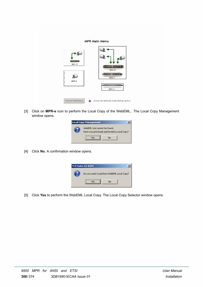
User Manual
Installation
9500 MPR for ANSI and ETSI
3DB19901ECAA Issue 01308/374
[3] Click on MPR-e icon to perform the Local Copy of the WebEML.. The Local Copy Managementwindow opens.
[4] Click No. A confirmation window opens.
[5] Click Yes to perform the WebEML Local Copy. The Local Copy Selector window opens.

User Manual
Installation
9500 MPR for ANSI and ETSI
3DB19901ECAA Issue 01 309/374
[6] Select the SW component to copy and click on Copy.
[7] Select the directory and click Open.
Warning: Special characters (like #...) cannot be used.
[8] The copy is now in progress.

User Manual
Installation
9500 MPR for ANSI and ETSI
3DB19901ECAA Issue 01310/374
[9] Wait until the following message will appear. Click OK.
[10] Click Yes to set a link on the desktop.
[11] Perform one of the following:
c) Double click on the WebEML icon on the desktop to start the application for MPR-estandalone.Double click on the MCT Launcher icon on the desktop to start the applicationfor MPR-e in Single NE mode with 7705 SAR (applicable to 9500 MPR Release 4.1.0).
Note: An alternative way to perform the Local Copy of the WebEML is the following:
[1] Click on the Advanced Settings button below.

User Manual
Installation
9500 MPR for ANSI and ETSI
3DB19901ECAA Issue 01 311/374
[2] Select one of the two Advanced Settings options to copy software to the PC.
� Java JRE Package Installation (par. 4.4.4.1 on page 312)
� Local Copy of WebEML (JUSM/CT) (par. 4.4.4.2 on page 312)

User Manual
Installation
9500 MPR for ANSI and ETSI
3DB19901ECAA Issue 01312/374
4.4.4.1 Java JRE package installation
[1] Click on the Java JRE Package Installation button to install the Sun Java Runtime Environment33 version to your PC.
4.4.4.2 Local copy of WebEML (JUSM/CT)
[1] Click on the Local Copy of WebEML (JUSM/CT) button to copy the WebEML software to your PC.Choose the directory location and click Open and then OK.
[2] When the files have finished copying, this window will display. Click the OK button.
[3] Click Yes to set a link on the desktop.
[4] Two icons will be created on the desktop: one for the WebEML (used for MPR-e standalone) andone for the MCT Launcher (used for MPR-e Release 4.1.0 in Single NE with SAR).
Figure 254 WebEML desktop icon

User Manual
Installation
9500 MPR for ANSI and ETSI
3DB19901ECAA Issue 01 313/374
Figure 255 MCT Launcher desktop icon
4.4.5 Configure the PC Network card for the connection to the MPR-e standalone
Two options are available:
� Option 1: PC connected to the traffic port of MPT (par. 4.4.5.1 on page 313)
� Option 2: PC connected to GEthernet generic device (par. 4.4.5.2 on page 316)
Note: Option 1 is mandatory for 1+0 repeater configuration.
4.4.5.1 Option 1: PC connected to the traffic port of MPT
This example uses a Microsoft Windows 7 Professional system and refers to the first installation (defaultvalues), when the MPR-e has never been configured.
[1] Connect a CAT 5/5E cable from the MPR-e to the PC network card.
[2] Open up the NETWORK CONNECTIONS. Highlight the network card as shown below.
[3] PC configuration Enable VLAN management.

User Manual
Installation
9500 MPR for ANSI and ETSI
3DB19901ECAA Issue 01314/374
[4] PC configuration: Network Address.

User Manual
Installation
9500 MPR for ANSI and ETSI
3DB19901ECAA Issue 01 315/374
The PC must be in the same sub network as the IP interface on the MDA card of the 7705 SAR.

User Manual
Installation
9500 MPR for ANSI and ETSI
3DB19901ECAA Issue 01316/374
4.4.5.2 Option 2: PC connected to GEthernet generic device
This example uses a Microsoft Windows XP Professional system and refers to the first installation (defaultvalues), when the MPR-e has never been configured.
[1] Connect a CAT 5/5E cable from the PC network card to the FE port of the GEthernet Generic Device.
[2] Click on the START menu on the Windows desktop and open up the CONTROL PANEL.
[3] Open up the NETWORK CONNECTIONS. Highlight the network card as shown below.

User Manual
Installation
9500 MPR for ANSI and ETSI
3DB19901ECAA Issue 01 317/374
[4] Double click on Properties to display the screen below and scroll down the list to highlight theInternet Protocol (TCP/IP) line. Click the OK button.
[5] Enter, as example, the IP address 192.168.100.2 (subnet mask: 255.255.255.0) for the PC networkcard as shown below. Click OK.
Note: The NE default IP address is 192.168.100.1 (mask 255.255.255.0); for this reason the PC IPaddress must belong to the same mask.
Note: It is suggested to keep enabled only one network connection on a PC.

User Manual
Installation
9500 MPR for ANSI and ETSI
3DB19901ECAA Issue 01318/374
[6] To check the connectivity between the PC and the NE, open up a DOS window or Command Prompt.Click on the START menu on the Windows desktop and open up the RUN window as shown below.
[7] Type cmd and click OK to open up a DOS window.
[8] The DOS window will display.
[9] In the DOS window, click the cursor after the > and type ping 192.168.100.1 to verify a connectionbetween the PC and the NE. The Ping statistics for the IP address 192.168.100.1 should display 4packets sent and 4 packets received.
Note: The 192.168.100.1 IP address is the default NE In-band IP address.

User Manual
Installation
9500 MPR for ANSI and ETSI
3DB19901ECAA Issue 01 319/374
4.4.5.3 Possible error messages
NEtO Launching: Error message
Action > Verify IP connectivity with ping
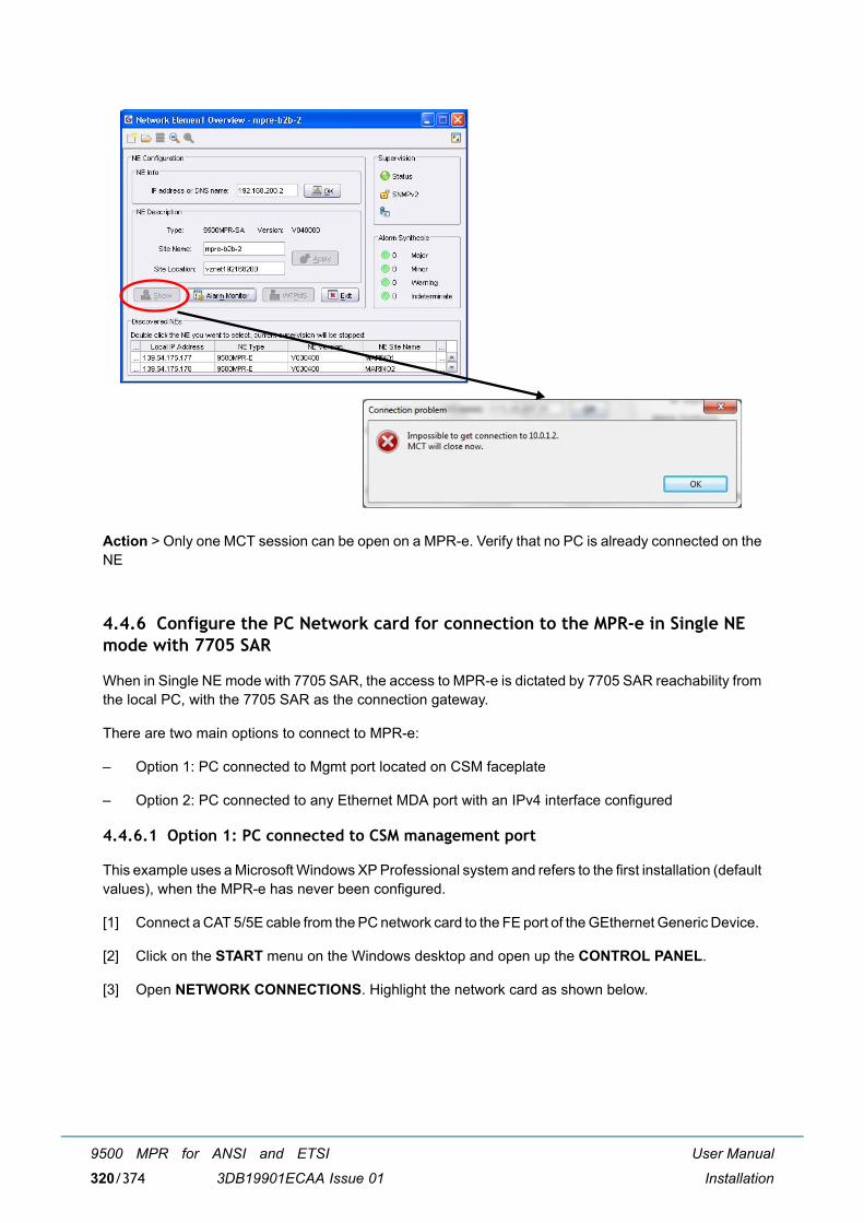
User Manual
Installation
9500 MPR for ANSI and ETSI
3DB19901ECAA Issue 01320/374
Action > Only one MCT session can be open on a MPR-e. Verify that no PC is already connected on theNE
4.4.6 Configure the PC Network card for connection to the MPR-e in Single NE mode with 7705 SAR
When in Single NE mode with 7705 SAR, the access to MPR-e is dictated by 7705 SAR reachability fromthe local PC, with the 7705 SAR as the connection gateway.
There are two main options to connect to MPR-e:
� Option 1: PC connected to Mgmt port located on CSM faceplate
� Option 2: PC connected to any Ethernet MDA port with an IPv4 interface configured
4.4.6.1 Option 1: PC connected to CSM management port
This example uses a Microsoft Windows XP Professional system and refers to the first installation (defaultvalues), when the MPR-e has never been configured.
[1] Connect a CAT 5/5E cable from the PC network card to the FE port of the GEthernet Generic Device.
[2] Click on the START menu on the Windows desktop and open up the CONTROL PANEL.
[3] Open NETWORK CONNECTIONS. Highlight the network card as shown below.

User Manual
Installation
9500 MPR for ANSI and ETSI
3DB19901ECAA Issue 01 321/374
[4] Double click on Properties to display the screen below and scroll down the list to highlight theInternet Protocol (TCP/IP) line. Click the OK button.
[5] Enter, for example, the IP address 192.168.100.2 (subnet mask: 255.255.255.0) for the PC networkcard as shown below. Click OK.
Note: The PC IP address must belong to the same subnet mask as the IP address of the managementport of the 7705 SAR.
Note: It is suggested to keep enabled only one network connection on a PC.

User Manual
Installation
9500 MPR for ANSI and ETSI
3DB19901ECAA Issue 01322/374
[6] To check the connectivity between the PC and the NE, open up a DOS window or Command Prompt.Click on the START menu on the Windows desktop and open up the RUN window as shown below.
[7] Type cmd and click OK to open up a DOS window.
[8] The DOS window will display.

User Manual
Installation
9500 MPR for ANSI and ETSI
3DB19901ECAA Issue 01 323/374
[9] In the DOS window, click the cursor after the > and type ping 192.168.100.1 to verify a connectionbetween the PC and the NE. The Ping statistics for the IP address 192.168.100.1 should display 4packets sent and 4 packets received.
Note: The 192.168.100.1 IP address is the default NE In-band IP address.
4.4.6.2 Option 2: PC connected to Ethernet MDA port
When PC is connected to any Ethernet MDA port, port encapsulation drives the PC network adapterconfiguration.
If the configured encapsulation is dot1q, a VLAN must be configured on the PC network adapter. On thecontrary, if encapsulation is null, no VLAN tag is required and the configuration steps are exactly the sameas for Option 1.
This example uses a Microsoft Windows 7 Professional system and refers to the first installation (defaultvalues), when the MPR-e has never been configured.

User Manual
Installation
9500 MPR for ANSI and ETSI
3DB19901ECAA Issue 01324/374
[1] Connect a CAT 5/5E cable from the MPR-e to the PC network card.
[2] Open NETWORK CONNECTIONS. Highlight the network card as shown below.
[3] PC configuration Enable VLAN management.

User Manual
Installation
9500 MPR for ANSI and ETSI
3DB19901ECAA Issue 01 325/374
[4] PC configuration: Network Address.

User Manual
Installation
9500 MPR for ANSI and ETSI
3DB19901ECAA Issue 01326/374
The default IP address for TMN in Band is 192.168.100.1.
The PC must be in the same sub network.
4.4.6.3 Possible error messages
Error reported when clicking on MPR-e not connected to a 7705 SAR either because it is powered off orbecause Ethernet cable is not connected at one or both ends.
Figure 256 Unavailable MPR-e error
Error reported when connection with the 7705 SAR is lost. The MCT Launcher will close, along with allMCT sessions.

User Manual
Installation
9500 MPR for ANSI and ETSI
3DB19901ECAA Issue 01 327/374
Figure 257 MCT sudden closure
Figure 258 MCT Launcher sudden closure

User Manual
Installation
9500 MPR for ANSI and ETSI
3DB19901ECAA Issue 01328/374

User Manual
Provisioning
9500 MPR for ANSI and ETSI
3DB19901ECAA Issue 01 329/374
5 Provisioning
5.1 MPR-e standalone provisioning
This chapter describes the first installation procedures to configure the NE.
Since MPR-e is a stand alone equipment, for its provisioning there are 2 possible options:
� Option 1: MPR-e will be FIRST configured through the PC and AFTER connected to the GEthernetgeneric device (par. 5.1.1 on page 330)
� Option 2: MPR-e will be directly configured through the GEthernet generic device (par. 5.1.2 on page334)
Here is an overview of the options detailed in this chapter.
Table 73. Provisioning option
Note: For the provisioning of the 1+0 repeater configuration, Option 1B is applicable.
Provisioningthrough
GEthernet Generic Device
connectivity
MPT-MCMPT-HC V2/
MPT-XP/9558HC
Option 1(PC)
Option BOptical -
Provisioning must be performed before HW installation of MPT
Option AElectrical
MPR-e can always be installed on pole mounting before provisioning
MPR-e can always be installed on pole mounting before provisioning
Option 2(GEthernet
GenericDevice)
Option BOptical -
MPR-e can always be installed on pole mounting before provisioning
Option AElectrical
MPR-e can always be installed on pole mounting before provisioning

User Manual
Provisioning
9500 MPR for ANSI and ETSI
3DB19901ECAA Issue 01330/374
5.1.1 Option1: MPR-e will be configured through the PC
5.1.1.1 Prerequisites for the PC
� 1 Gb Ethernet interface (mandatory)
� VLAN management capability
� For the configuration please refer to paragraph 4.4.5 on page 313.
5.1.1.2 MPR-e interconnection option
In paragraph 4.1 on page 191 are described the possible options for hardware installation after the firststep of provisioning of the equipment.
MPT-MC can only be connected through electrical connection.
Table 74.is the summary table.
Table 74. Summary table
5.1.1.2.1 Option A: MPR-e is interconnected to the GEthernet generic device in electrical
MPR-e can always be installed on the pole mounting before provisioning.
5.1.1.2.2 Option B: MPR-e is interconnected to the GEthernet generic device in optical
The configuration will not be possible from PC through SFP optical port (no PC are equipped), asconsequence the provisioning must be performed through electrical interface BEFORE to install the MPR-e on the pole mounting with its final optical connectors.
MPT-HC V2/MPT-XP/9558HC
MPT-MC
OpticalDC Coaxial cable
-Data Fiber cable
ElectricalDC
CAT5e cable (PFoE) CAT5e cable (PFoE)Data

User Manual
Provisioning
9500 MPR for ANSI and ETSI
3DB19901ECAA Issue 01 331/374
5.1.1.3 Procedure
[1] Set up the interconnections to MPR-e in electrical:
� MPT-MC/MPT-HC V2/MPT-XP/9558HC interconnection:
Note: MPT-MC/MPT-HC V2/MPT-XP/9558HC can be installed on the pole-mounting.
[2] Verify on the PC, that the WebEML application has been installed (if not, refer to paragraph 4.4.4on page 307 to install it).
[3] Configure the PC network card interface. See paragraph 4.4.5 on page 313.
[4] Start the WebEML following the paragraph 3.1 on page 123.
Depending on the WebEML version you are using and the MPR-e Software Package version (NErelease) loaded in the MPR-e, you can experience 2 different situations:
[5] Situation 1: the main screen of the MPR-e opens. You have to check if the MPR-e Software Packageversion must be up-dated or not. If needed, proceed as described in paragraph 3.8.1.2 on page 133.
[6] Situation 2: You are not able to click on the Show button of the NEtO and a popup messageindicating a version mismatch is displayed:
This means that the MPR-e Software Package version is newer than the WebEML version. As anexample, in the picture, the NE Software Package loaded in the MPR-e is , while the most recentWebEML version is .
Note: this kind of situation is explained by the fact that ALU regularly introduced new NE releasein production, that could be not the one you are using on your network.
[7] In such case, press the Yes button to have access to the Show button:

User Manual
Provisioning
9500 MPR for ANSI and ETSI
3DB19901ECAA Issue 01332/374
[8] Click on the Show button. The following message will be displayed to inform that mismatch betweenMCT version and NE Software Package:
[9] Clicking on the Downgrade NE button will allow you to downgrade the NE Software Package. Thefollowing screen is displayed:

User Manual
Provisioning
9500 MPR for ANSI and ETSI
3DB19901ECAA Issue 01 333/374
Warning: After the activation of the Standby bank, the connection between WebEML and MPR-e islost.
[10] Proceed as described in paragraph 3.8.1.2 on page 133. The MPR-e will reset after the activationof the Standby Software Package causing the lost of the connection.
[11] Re-open the WebEML.
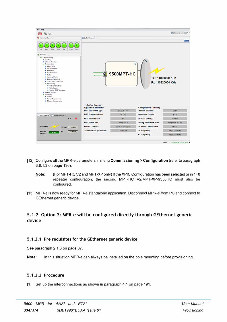
User Manual
Provisioning
9500 MPR for ANSI and ETSI
3DB19901ECAA Issue 01334/374
[12] Configure all the MPR-e parameters in menu Commissioning > Configuration (refer to paragraph3.8.1.3 on page 136).
Note: (For MPT-HC V2 and MPT-XP only) If the XPIC Configuration has been selected or in 1+0repeater configuration, the second MPT-HC V2/MPT-XP-9558HC must also beconfigured.
[13] MPR-e is now ready for MPR-e standalone application. Disconnect MPR-e from PC and connect toGEthernet generic device.
5.1.2 Option 2: MPR-e will be configured directly through GEthernet generic device
5.1.2.1 Pre requisites for the GEthernet generic device
See paragraph 2.1.3 on page 37.
Note: in this situation MPR-e can always be installed on the pole mounting before provisioning.
5.1.2.2 Procedure
[1] Set up the interconnections as shown in paragraph 4.1 on page 191.
User Manual
Provisioning
9500 MPR for ANSI and ETSI
3DB19901ECAA Issue 01 335/374
[2] Verify on the PC, that the WebEML application has been installed (if not, refer to paragraph 4.4.4on page 307 to install it).
[3] Configure PC network card interface. See paragraph 4.4.5 on page 313.
[4] Start the WebEML following the paragraph 3.1 on page 123.
See point [5] to point [13] of paragraph 5.1.1.3 on page 331.
5.2 MPR-e provisioning in Single NE mode with 7705 SAR
5.2.1 7705 SAR pre-requisites
See paragraph 2.1.4 on page 335.
5.2.2 Procedure
[1] Set up the interconnections, as shown in Figure 160.
[2] Verify on the PC that the MCT Launcher application has been installed (if not, refer to paragraph4.4.4 on page 307 to install it).
[3] Configure PC network card interface. See paragraph 4.4.6 on page 320.
[4] Start the MCT Launcher following the paragraph 3.3 on page 126. The main screen of the MCTLauncher opens.
[5] Configure all the MPR-e parameters in menu Commissioning > Configuration (see paragraph 3.8.1.3on page 136).
Note: (For MPT-HC V2 and MPT-XP only) If the XPIC Configuration has been selected or in 1+0repeater configuration, the second MPT-HC V2/MPT-XP must also be configured.
The MPR-e is now ready.

User Manual
Provisioning
9500 MPR for ANSI and ETSI
3DB19901ECAA Issue 01336/374

User Manual
Maintenance and trouble-clearing
9500 MPR for ANSI and ETSI
3DB19901ECAA Issue 01 337/374
6 Maintenance and trouble-clearing
6.1 Introduction
This section contains information and procedures to aid in restoring the equipment to its proper operatingcondition after it has been determined that a problem exists.
The following warnings and cautions apply while operating, performance testing, troubleshooting, orrepairing the 9500 MPR series radios.
Short circuits in low-voltage, low-impedance dc circuits can cause severe arcing that may result in burns or eye injury. Remove rings,
watches, and other metal jewelry while working with primary circuits. Exercise caution to avoid shorting power input terminals.
Units with the electrostatic-sensitive (ESS) symbol contain ESS devices. Store these units in an antistatic container when not in use, and anyone handling a unit should observe antistatic precautions.
Refer to the Special Precautions pages in the front of the instruction book for detailed handling information.
Note: Ensure that all antennas are properly aligned and waveguide is in good physical condition.
Note: Before performing procedures that might in any way affect transmission, it is recommended that the person performing the procedure understand the Rules and Regulations pertaining to the equipment and be properly authorized to operate the equipment.
6.2 Maintenance philosophy
This section provides information and procedures for equipment maintenance down to the Card level.Card repair is not covered in this manual.

User Manual
Maintenance and trouble-clearing
9500 MPR for ANSI and ETSI
3DB19901ECAA Issue 01338/374
The use of maintenance procedures in this section may result from failure of a periodic check, an alarmindication, or unacceptable performance.
For information about Maintenance on MPR-e directly connected to 7705 SAR system, see the SARdocumentation: this document addresses only the MPR-e maintenance. In addition, considering the levelof integration between two systems and their joint behavior, maintenance operation must always involvepeople with knowledge of both MPR-e and the 7705 SAR.
6.3 Personal computer (PC)/laptop
Connect the PC to the FE port of the GEthernet Generic Device.
6.4 Troubleshooting
This section provides guidance on:
� Before Going to Site Checklist
� Troubleshooting Basics
� Troubleshooting Path Problems
6.4.1 Before going to site checklist
Where possible, before going to site obtain the following information:
� Does the fault require immediate attention?
� Determine who is the best-placed person to attend the fault.
� Confirm the nature and severity of the reported fault, its location, MPT type, frequency band, high/low end MPT, capacity modulation and configuration. Ask:
� Is just one link affected, or a number of links in the same geographical area?
� Is the path down completely or is traffic passing but with a BER alarm?
� Could the fault be in the equipment connected to MPT, rather than in MPT? Are there alarmson other, connected equipment?
� Is it a hard or intermittent fault?
� Do alarms confirm which end of an alarmed link is faulty?
� Could the weather (rain, ice, high wind, temperature) be a factor in the reported fault?
Note: If the fault suggests a rain fade or other weather related fade condition and it matches the prevailing weather conditions, do not take any action until the weather abates.
� Does link history suggest any fault trends?

User Manual
Maintenance and trouble-clearing
9500 MPR for ANSI and ETSI
3DB19901ECAA Issue 01 339/374
� Does the fault history for the link indicate a likely cause?
� Is the link newly installed?
� Has there been any recent work done on the link?
� Ensure that you have with you:
� Appropriate spares. Where an equipment failure is suspected, these should includereplacement of the MPR-e. If an MPR-e is suspected then local/national climbing safetyrequirements must be adhered to.
� A laptop PC loaded with Craft Terminal, and an Ethernet cable. If an Ethernet connection is tobe used, you need the IP address and also the addresses for any remote sites to be accessed.
� If login security has been enabled, you need the password for the local and also any remotesites to be accessed.
� Any special test equipment that may be needed, such as a BER tester.
� Toolkit.
� Key(s) for access to the site.
6.4.2 PC troubleshooting
In case of the NE is not displayed in the NEtO screen, the MCT has to be launched directly through MctStarter.jar located under the path created by the operator during the local copy and under \\WebEML MPR TCO \9500MCT_\MctStarter.jar
6.4.3 Troubleshooting basics
This section provides general guidance on troubleshooting:
� Check the MCT screen. Connect the PC to the GEthernet Generic Device. When logging to theequipment with Craft Terminal, the opening screen is the Main Screen. Use the information providedin menu Alarms (par. 3.8.5.1 on page 182) and in menu Events (par. 3.8.5.5 on page 189) to checkfor severity and problem type.
Refer to Table 75, Table 76 and Table 77 for probable cause and recommended action.
Table 75 MPT-HC V2/MPT-MC/MPT-XP/9558HC alarm matrix (equipment type)
Alarm description
Alarm displayed on MCT Filtering rule (Note 1)
Most probable cause
Action
Probable cause Specific Problem
MPT Card fail (Tx fail, Rx fail, Mod fail)
Replaceable Unit Problem (RUP)
Tx BB LO UnlockedRF LO UnlockedRx IF LO UnlockedRx BB LO UnlockedModem Tx SynchronizationTx Power
no MPT failed Replace the MPT

User Manual
Maintenance and trouble-clearing
9500 MPR for ANSI and ETSI
3DB19901ECAA Issue 01340/374
Legend:
� (*): only for MPT-HC V2/MPT-XP in XPIC configuration
� (***): only for MPT-HC V2/MPT-XP/9558HC
Note: the alarm in the �Alarm description� column is masked, if one alarm (at least) listed in the�Filtering rule� column (on the relevant row) is active.
MPT Module Card Fail (***)
Replaceable Unit Problem (RUP)
MPT Plug-in RI Access Failure if XPIC plug-in add;XPIC Plug-in Power Supply Failure;XPIC Inter-Modem Calibration Failure
no MPT failed Replace the MPT
SFP traffic missing
Replaceable Unit Missing
no SFP traffic missing or type mismatch
Plug or check the optical SFP
Traffic SFP card fail
Replaceable Unit Problem (RUP)
SFP traffic missing
The optical SFP is failed
Replace the optical SFP
Incompatible Shifter
Incompatible Shifter no Configured shifter value not supported by the MPT
Re-configure shifter value
Incompatible Frequency
Incompatible Frequency
Incompatible Shifter
Configured frequency value not supported by the MPT
Re-configure frequency value
Incompatible Modulation
Incompatible Modulation
no Configured modulation value not supported by the MPT
Re-configure modulation value
Incompatible Power
Incompatible Power no Configured Tx Power value not supported by the MPT
Re-configure Tx Power value
XPIC cable loss (*)
Demodulator XPIC Loss Of Signal
MPT Module Card Fail
Loss of Signal on the XPIC interface
Check the cable
Coupling port SFP missing (*)
Replaceable Unit Missing
no The SFP plug-in is missing or type mismatched
Plug or check the SFP plug-in
Coupling port SFP card fail (*)
Replaceable Unit Problem (RUP)
Coupling Port SFP missing
The SFP plug-in is failed
Replace the SFP plug-in
Alarm description
Alarm displayed on MCT Filtering rule (Note 1)
Most probable cause
Action
Probable cause Specific Problem

User Manual
Maintenance and trouble-clearing
9500 MPR for ANSI and ETSI
3DB19901ECAA Issue 01 341/374
Table 76 MPT-HC V2/MPT-MC/MPT-XP/9558HC alarm matrix (communication type)
Alarm description
Alarm displayed on MCT
Filtering rule (Note 1)
Most probable cause Action
Probable cause
Ethernet Link Down
Loss of Signal SFP traffic missing (if optical)
Bad connection to the GEthernet Generic Device
Check the cable
Demodulation function failure
Demodulator Failure
MPT Card Fail Internal receive circuit failure
Replace the MPT
MPT Main Loss of Radio Frame
Loss Of Frame Demodulation function failure MPT Card Fail
Far end problems, RF path problems, or local circuit failures have caused BER to increase to the point that frames are being lost
1. Check/troubleshoot far end alarms 2. Replace alarmed MPT
Link Identifier Mismatch
Link Identifier Mismatch
MPT Main Loss of Radio FrameDemodulation function failureMPT Card Fail
Link identifier number provisioned is different from link identifier number provisioned at other end of hop
Set numbers at both ends of hop to match
High BER (HBER)
High BER Demodulation function failureMPT Main Loss of Radio FrameLink Identifier MismatchMPT Card Fail
Bit Error Rate threshold (10E-4) exceeded
1. Verify RF path is clear, antenna is aligned, and no existing weather-related problems 2. Verify RSL is above RCV threshold. If not - check upstream transmitter output/troubleshoot transmitter
Early Warning (EW)
Early Warning HBERDemodulation function failureMPT Main Loss of Radio FrameLink Identifier MismatchMPT Card Fail
10E-9 BER detected No action is required at this time. Monitor receive signal for increased degrading
MPT Main Communication Loop
Loop Problem no Communication problem between the local MPT and the remote MPT for all the functionalities requiring a communication loop (ATPC or ACM)
Check the radio hop
ANSI_ATPC_TimeOut
Atpc High Power Timeout
no Alarm only managed in ANSI mode and raised when Tx power level is at ATPC max level during 5 consecutive minutes
Check the radio hop
PPP fail PPP Failure no 1) PPP RF channel not enabled in both stations of the radio link 2) Restart of remote MPT on-going (following a SW Download operation) 3) Radio path broken
1) Verify PPP RF enabled 2) Wait MPT restart finalization 3) Verify the RF path

User Manual
Maintenance and trouble-clearing
9500 MPR for ANSI and ETSI
3DB19901ECAA Issue 01342/374
Legend:
� (*): only for MPT-HC V2/MPT-XP in XPIC configuration
Note: the alarm in the �Alarm description� column is masked, if one alarm (at least) listed in the�Filtering rule� column (on the relevant row) is active.
Table 77 MPT-HC V2/MPT-MC/MPT-XP/9558HC alarm matrix (quality of service type)
Note: the alarm in the �Alarm description� column is masked, if one alarm (at least) listed in the�Filtering rule� column (on the relevant row) is active.
Coupling ethernet link down (*)
Loss Of Signal Coupling Port SFP missing
Communication between MPT is failed
Check the cable
Coupling ethernet link error (*)
Ethernet Signal Degraded
Coupling Ethernet link downCoupling Port SFP missing
For the MPT Coupling optical port, the ratio between the number of received errored packets and the total number of received packets is above a given threshold.
Check the cable
Inter MPT communication problem (*)
Internal Communication Problem (ICP)
no Communication between the 2 MPT locally connected with ethernet cable is failed
Replace the MPT
Alarm description
Alarm displayed on MCT Filtering rule (Note 1)
Most probable cause
Probable cause Type Specific Problem
TCA on Radio Hop (15 minutes)
Threshold Crossed
Quality of Service
Radio Hop 15 Minutes BBE Radio Hop 15 Minutes ES Counter Radio Hop 15 Minutes SES Counter
no Alarm threshold exceeded
TCA on Radio Hop (24 hours)
Threshold Crossed
Quality of Service
Radio Hop 24 Hours BBE Radio Hop 24 Hours ES Counter Radio Hop 24 Hours SES Counter
no Alarm threshold exceeded
UAT on Radio Hop
Unavailable Time
Quality of Service
Radio Hop 15 Minutes UAT Radio Hop 24 Hours UAT
no 10 consecutive SES (unavailable time period)
Alarm description
Alarm displayed on MCT
Filtering rule (Note 1)
Most probable cause Action
Probable cause

User Manual
Maintenance and trouble-clearing
9500 MPR for ANSI and ETSI
3DB19901ECAA Issue 01 343/374
6.4.4 Relationship between the alarms on the MCT and SNMP traps
Table 78 MPT SNMP traps (Equipment Type)
Alarm description
MCT SNMP Traps
Probable cause Specific Problem Probable cause Managed object
MPT Card fail (Tx fail, Rx fail, Mod fail)
Replaceable Unit Problem (RUP)
Tx BB LO UnlockedRF LO UnlockedRx IF LO UnlockedRx BB LO UnlockedModem Tx Synchronization Tx Power
Replaceable Unit Problem (RUP) (opticsIMAlarmReplaceableUnitProblem)
Entry corresponding to faulty MPT in equipment table
MPT Module Card Fail (***)
Replaceable Unit Problem (RUP)
MPT Plug-in RI Access Failure if XPIC plug-in add;XPIC Plug-in Power Supply Failure;XPIC Inter-Modem Calibration Failure
Replaceable Unit Problem (RUP) (opticsIMAlarmReplaceableUnitProblem)
Entry corresponding to faulty MPT module in equipment table
SFP traffic missing
Replaceable Unit Missing
Replaceable Unit Missing(opticsIMAlarmReplaceableUnitMissing)
Entry corresponding to missing SFP in equipment table
Traffic SFP card fail
Replaceable Unit Problem (RUP)
Replaceable Unit Problem (RUP)(opticsIMAlarmReplaceableUnitProblem)
Entry corresponding to faulty SFP in equipment table
Incompatible Shifter
Incompatible Shifter
Incompatible Shifter (opticsIMAlarmIncompatibleShifter)
Entry corresponding to faulty radio port in ifTable
Incompatible Frequency
Incompatible Frequency
Incompatible Frequency (opticsIMAlarmIncompatibleFrequency)
Entry corresponding to faulty radio port in ifTable
Incompatible Modulation
Incompatible Modulation
Incompatible Modulation Parameter (opticsIMAlarmIncompatibleModulationParam)
Entry corresponding to faulty radio port in ifTable
Incompatible Power
Incompatible Power
Incompatible PTx (opticsIMAlarmIncompatiblePTX)
Entry corresponding to faulty radio port in ifTable
XPIC cable loss (*)
Demodulator XPIC Loss Of Signal
Dem XPIC Loss of Signal(opticsIMAlarmDemXpicLOS)
Entry corresponding to faulty MPT module in equipment table
Coupling port SFP missing (*)
Replaceable Unit Missing
Replaceable Unit Missing(opticsIMAlarmReplaceableUnitMissing)
Entry corresponding to faulty SFP on MPT1 coupling port in equipment table
Coupling port SFP card fail (*)
Replaceable Unit Problem (RUP)
Replaceable Unit Problem (RUP)(opticsIMAlarmReplaceableUnitProblem)
Entry corresponding to faulty SFP on MPT1 coupling port in equipment table

User Manual
Maintenance and trouble-clearing
9500 MPR for ANSI and ETSI
3DB19901ECAA Issue 01344/374
Legend:
� (*): only for MPT-HC V2/MPT-XP in XPIC configuration
� (***): only for MPT-HC V2/MPT-XP/9558HC
Table 79 MPT SNMP traps (communication type)
Legend:
� (*): only for MPT-HC V2/MPT-XP in XPIC configuration
Alarm description
MCT SNMP Traps
Probable cause Probable cause Managed object
Ethernet Link Down Loss of Signal Loss Of SignalopticsIMAlarmLossOfSignal)
Entry corresponding to faulty user ethernet port in ifTable
Demodulation function failure
Demodulator Failure Dem Fail (opticsIMAlarmDemFail)
Entry corresponding to faulty MPT in equipment table
MPT Main Loss of Radio Frame
Loss Of Frame Loss Of Frame (opticsIMAlarmLossOfFrame)
Entry corresponding to faulty radio port in ifTable
Link Identifier Mismatch
Link Identifier Mismatch
Link Identifier Mismatch (opticsIMAlarmLinkIdentifierMismatch)
Entry corresponding to faulty MPT in equipment table
High BER (HBER) High BER High BER (opticsIMAlarmHighBER)
Entry corresponding to faulty MPT in equipment table
Early Warning (EW) Early Warning Early Warning (opticsIMAlarmEarlyWarning)
Entry corresponding to faulty MPT in equipment table
MPT Main Communication Loop
Loop Problem Loop Problem (opticsIMAlarmLoopProblem)
Entry corresponding to faulty radio port in ifTable
ANSI_ATPC_TimeOut Atpc High Power Timeout
Alarm ATPC Timeout (opticsIMAlarmATPCTimeout)
Entry corresponding to faulty radio port in ifTable
PPP fail PPP Failure PPP Fail (opticsIMAlarmPPPFail)
Entry corresponding to faulty radio port in ifTable
Coupling ethernet link down (*)
Loss Of Signal Loss Of SignalopticsIMAlarmLossOfSignal)
Entry corresponding to faulty SFP on MPT1 coupling port in equipment table
Coupling ethernet link error (*)
Ethernet Signal Degraded
Eth Signal Degraded(opticsIMAlarmEthSignalDegraded)
Entry corresponding to faulty SFP on MPT1 coupling port in equipment table
Inter MPT communication problem (*)
Internal Communication Problem (ICP)
Internal Communication Problem (opticsIMAlarmInternalCommunicationProblem)
Entry corresponding to the MPT in equipment table

User Manual
Maintenance and trouble-clearing
9500 MPR for ANSI and ETSI
3DB19901ECAA Issue 01 345/374
Table 80 MPT SNMP traps (quality of service type)
6.4.5 Troubleshooting path problems
A path-related problem, with the exception of interference, is characterized by traffic being similarlyaffected in both directions. Generally, if you are experiencing only a one-way problem, it is not a pathproblem.
Note: A path extends from MPR-e antenna port to MPR-e antenna port.
� Normally a path problem is signalled by a reduced RSL, and depending on its severity, a high BER.
� Only in worst case situations, such as an antenna knocked out of alignment, will a path failcompletely, and stay that way.
� For weather-related problems, such as rain or ducting, the path problem will disappear as theweather returns to normal.
6.4.5.1 Path problems on a commissioned link
A path problem on an existing link, one that has been operating satisfactorily may be caused by:
Alarm description
MCT SNMP Traps
Probable cause
Specific Problem Probable cause
Managed object
TCA on Radio Hop (15 minutes)
Threshold Crossed
Radio Hop 15 Minutes BBERadio Hop 15 Minutes ES CounterRadio Hop 15 Minutes SES Counter
Threshold Crossed (opticsIMAlarmTCA)
Entry corresponding to the faulty radio port ifIndex and the granularity index (=1 for 15mn) in opticsIMPdhFrameHopCurrentDataTable.
TCA on Radio Hop (24 hours)
Radio Hop 24 Hours BBERadio Hop 24 Hours ES CounterRadio Hop 24 Hours SES Counter
Threshold Crossed (opticsIMAlarmTCA)
Entry corresponding to the faulty radio port ifIndex and the granularity index (= 2 for 24h) in opticsIMPdhFrameHopCurrentDataTable.
UAT on Radio Hop
Unavailable Time
Radio Hop 15 Minutes UAT UnavailableTime (opticsIMA
larmUnavailableTime)
Entry corresponding to the faulty radio port ifIndex and the granularity index (=1 for 15mn) in opticsIMPdhFrameHopCurrentDataTable.
Radio Hop 24 Hours UAT UnavailableTime (opticsIMA
larmUnavailableTime)
Entry corresponding to the faulty radio port ifIndex and the granularity index (= 2 for 24h) in opticsIMPdhFrameHopCurrentDataTable.

User Manual
Maintenance and trouble-clearing
9500 MPR for ANSI and ETSI
3DB19901ECAA Issue 01346/374
� Weather-related path degradation
If BER alarms are fleeting/not permanent and RSL returns to its normal, commissioned level afterthe alarm is cleared, rain, diffraction, or multipath fading is indicated. Rain fade is the likely causeof fade for links 13 GHz and higher. Diffraction and multipath/ducting for links 11 GHz and lower. Ifthese alarms are persistent, there could be a problem with the link design or original installation.
� Changed antenna alignment or antenna feed problem
If RSLs do not return to commissioned levels after a period of exceptionally strong winds, suspectantenna alignment. Also, check the antenna for physical damage, such as may occur with ice-fall.For a remote-mounted MPT, check its antenna feeder.
� New path obstruction
Where all other parameters check as normal, and the path has potential for it to be obstructed byconstruction works, view/survey the path for possible new obstructions.
� Interference from other signal sources
Interference usually affects traffic in just one direction. Unlike other path problems, RSL is notaffected. If suspected, check for new link installations at, or in the same geographical area, as theaffected site. Ultimately, a spectrum analyzer may have to be used to confirm interference, which isnot an easy task given the need to connect directly to the antenna port, after removing the MPT.
6.4.5.2 Path problems on a new link
For a new link, potential problems can extend to also include:
� Incorrect antenna alignment
One or both antennas incorrectly aligned. Refer to Installation alignment procedure.
� Mismatching antenna polarizations
Given a typical polarization discrimination of 30 dB, for most links it is not possible to capture a signalto begin the antenna alignment process.
� Incorrect path calculations
If the RSLs are too low or too high, antenna alignment is correct, and Tx power settings are correct,check the path calculations used to determine the link performance. A good calculation match is± 2 dB. Disagreements in excess of 3 dB should be investigated.
� Reflections
Reflection (path cancellation) problems may not have been picked up at the path planning stage,particularly if the survey was a simple line-of-sight. If suspected, resurvey the path.
6.5 Equipment removal and replacement
6.5.1 MPT-HC V2/MPT-XP/9558HC removal and replacement
Disconnect the cables and connect them to the spare MPT-HC V2/MPT-XP/9558HC.

User Manual
Maintenance and trouble-clearing
9500 MPR for ANSI and ETSI
3DB19901ECAA Issue 01 347/374
Note: The MPT-HC V2 can also be used to replace the MPT-HC V1. The 23 GHz MPT-HC V2 is aTx High Power version vs. MPT-HC V1. Take in account it when MPT-HC V2 is used as spareof MPT-HC V1.
6.5.1.1 Replacement of an MPT-HC V2/MPT-XP in XPIC configuration
To replace an MPT-HC V2/MPT-XP in XPIC configuration it is mandatory to follow the following procedure:
1) Power off the MPT-HC V2/MPT-XP
2) Disconnect the XPIC cable
3) Disconnect the RPS cable
4) Disinstall the failed MPT-HC V2/MPT-XP
5) Install the spare MPT-HC V2/MPT-XP
6) Connect the RPS cable
7) Connect the XPIC cable
8) Power on the MPT-HC V2/MPT-XP
6.5.2 MPT-MC removal and replacement
Disconnect the cables and connect them to the spare MPT-MC.
6.6 Cleaning
Do not use acid, alcohol, or brushes to clean the equipment because damage to the silk-screen labeling and antistatic coating can
result. Cleaning should be confined to the removal of dust and dirt using a damp cloth.
Cleaning should normally be confined to the removal of dust and dirt using a soft bristled (natural fiber)brush and a low velocity blower (such as a vacuum cleaner with a plastic blower nozzle). Do not use acidor synthetic bristled brushes to clean cards that contain electrostatic-sensitive components.

User Manual
Maintenance and trouble-clearing
9500 MPR for ANSI and ETSI
3DB19901ECAA Issue 01348/374
User Manual
Line�up and commissioning
9500 MPR for ANSI and ETSI
3DB19901ECAA Issue 01 349/374
7 Line�up and commissioningThis chapter details all phases necessary for the equipment line�up and commissioning.
7.1 Introduction
7.1.1 General
This chapter details all phases necessary for the equipment line�up, commissioning, and acceptance,providing the user with the information needed to connect, power on, and perform a minimum turn�up ofa radio link comprising two MPR-e.
Note: If the radio link consists of one MPR-e and one MPR-e connected to an MSS-4/MSS-8/MSS-1c to commission the link refer to the specific MSS User Manual.
It is assumed that, at both premises (Station A and Station B), the mechanical installation and cabling ofthe INDOOR and OUTDOOR sections is completed, the antennas are installed and pre�positioned, andthe Indoor/Outdoor cables have been properly connected.
Any information needed to complete the above mentioned operations are out of the scope of this chapter.
Subject On page
Introduction 349
General 349
Safety�EMC�EMF�ESD norms and Cautions to avoid equipment damage 350
Conventions 350
Summary of the commissioning phases 351
Commissioning of STATION A � phase 1 (Turn up) 355
Commissioning of STATION B � phase 1 (Turn up) 356
Fine antenna alignment and preliminary checks � Stations A & B 356
End of commissioning phase 1 (Turn up) in STATION A 358
Commissioning station A � phase 2 (acceptance test) 358
Commissioning station B � Phase 2 (acceptance Test) 363
Final operations 363
Annex A: fine antenna alignment 363

User Manual
Line�up and commissioning
9500 MPR for ANSI and ETSI
3DB19901ECAA Issue 01350/374
For this purpose refer to the Installation section.
All the cables and measurement kits as described in Table 81. below are supposed to be available.
Table 81. Test and commissioning instruments
The Alcatel�Lucent Software package must have already been installed in the PC used as the MCT andthe same software version must be already present as commit version in the two Network Elements.
Note: An FTP server must be installed in the PC.
Before proceeding with line�up and commissioning, ensure that you have the equipment and accessoriesrequired for that purpose.
7.1.2 Safety�EMC�EMF�ESD norms and cautions to avoid equipment damage
Warning: to make sure of the continuity and avoid short circuit, all cables / connectors connections suchas RJ45, Coaxial, Ethernet, or Optical Fiber made in the field have to be verified and checked with Cabletester. The waterproofness must be also checked.
If not yet done, read whole Chapter 1 on page 19: it describes the operations and/or precautions to beobserved to safeguard operating personnel during the working phases, and to guarantee equipmentsafety. Read them with accuracy before to start every action on the equipment.
7.1.3 Conventions
To simplify the description of actions, the following symbols are in use:
INSTRUMENT QTY CHARACTERISTICS
Laptop computer running the NE software
(For the laptop characteristics refer to par. 4.4.2 on page 305)
1 TCO 4.x
Link Service kit cable (for MPR-e antenna alignment)
1
2 Ethernet Data Analyzers for Ethernet Data channel functionality tests
Multi�meter 1 Voltmeter AC and DC � Loop tester
Cable Tester 1 For RJ45, Ethernet, Optical fiber etc.
TRS1
1. MPR-E
1 Test Result Sheet, available as separate document
TDS2
2. MPR-A
1 Test Data Sheet, available as separate document
Symbol used Meaning
! Manual action
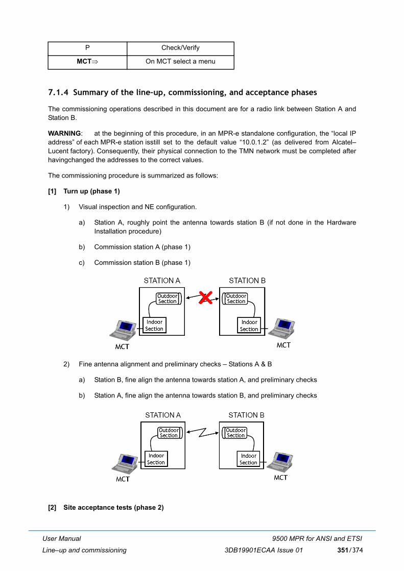
User Manual
Line�up and commissioning
9500 MPR for ANSI and ETSI
3DB19901ECAA Issue 01 351/374
7.1.4 Summary of the line�up, commissioning, and acceptance phases
The commissioning operations described in this document are for a radio link between Station A andStation B.
WARNING: at the beginning of this procedure, in an MPR-e standalone configuration, the �local IPaddress� of each MPR-e station isstill set to the default value �10.0.1.2� (as delivered from Alcatel�Lucent factory). Consequently, their physical connection to the TMN network must be completed afterhavingchanged the addresses to the correct values.
The commissioning procedure is summarized as follows:
[1] Turn up (phase 1)
1) Visual inspection and NE configuration.
a) Station A, roughly point the antenna towards station B (if not done in the HardwareInstallation procedure)
b) Commission station A (phase 1)
c) Commission station B (phase 1)
2) Fine antenna alignment and preliminary checks � Stations A & B
a) Station B, fine align the antenna towards station A, and preliminary checks
b) Station A, fine align the antenna towards station B, and preliminary checks
[2] Site acceptance tests (phase 2)
P Check/Verify
MCT⇒ On MCT select a menu

User Manual
Line�up and commissioning
9500 MPR for ANSI and ETSI
3DB19901ECAA Issue 01352/374
3) Station A, perform all the commissioning checks and tests � Report the results in the TRS.
4) Station B, perform all the commissioning checks and tests � Report the results in the TRS.
7.1.5 MCT connection
Two options are possible for MPR-e standalone:
� MCT can be connected to the GEthernet Generic Device, as shown in paragraph 4.1 on page 191.See the pre-requisites in paragraph 2.1.3 on page 37.
� MCT can be connected directly to the MPR-e (or to the Power Injector). The PC must have a 10/100/1000BaseT Ethernet network card and the VLAN tagging feature.
When in Single NE mode with 7705 SAR, the MCT Launcher shall be used as shown in paragraph 4.2on page 199. The IP address to be used for connection is any reachable IPv4 address of the 7705 SAR.Connection is always possible as long as the 7705 SAR is reachable.
7.1.6 How to access the remote MPR-e standalone
Figure 259 Accessing the remote MPR-e standalone
Configuration example of MPR-e standalone in STATION A
- NE Local IP address: 172.168.60.1
- NE TMN In-band IP address: 192.168.50.2
Configuration example of MPR-e standalone in STATION B
- NE Local IP address: 172.168.60.2.
Note: The local and remote NE IP addresses must be in the same sub-network.
The PC, as shown in Figure 259, is connected to the equipment in Station A and with the MCT we haveto access also the equipment in Station B.
How to configure the PC
� Assign to the PC an IP address in the same sub-net of the TMN In-band interface.
� Configure a static route with this command: "route add 0.0.0.0 mask 0.0.0.0 192.168.50.2" (IPaddress of the TMN In-band working as Gateway).

User Manual
Line�up and commissioning
9500 MPR for ANSI and ETSI
3DB19901ECAA Issue 01 353/374
� Or in the IP configuration of the Ethernet Interface set the Default Gateway to 192.168.50.2 (NE ATMN In-band IP address).
Note: The PC must add a VLAN tag in the frames sent to the TMN In-band, if connected directly tothe NE A. The VLAN ID must be the same as the one configured in the NE.
Two options are available:
� Option 1: with OSPF
� Option 2: without OSPF
7.1.6.1 Option 1: with OSPF
How to configure the MPR-e standalone in Station A
� Enable the "TMN RF" and associate to the TMN-RF an OSPF Area in menu Configuration >Networking > Network interfaces.
� Associate to the TMN In-band interface an OSPF Area in menu Configuration > Networking >Network interfaces.
How to configure the MPR-e standalone in Station B
� Enable the "TMN RF" and associate to the TMN-RF an OSPF Area in menu Configuration >Networking > Network interfaces. The OSPF area in MPR-e standalone in Stations A and B mustbe the same one.
7.1.6.2 Option 2: without OSPF
How to configure the MPR-e standalone in Station A
� Enable the "TMN RF" in menu Configuration > Networking > Network interfaces.
How to configure the MPR-e standalone in Station B
� Enable the "TMN RF" in menu Configuration > Networking > Network interfaces.
� Add the Static route "Default 0.0.0.0 0.0.0.0 Link on radio side" in menu Configuration >Networking > Static Routing.
� Or Add a static route to Network 192.168.50.0 255.255.255.0 Link on radio side.
� Or Add a static route to Host 192.168.50.x (PC IP address) 255.255.255.255 Link on radio side.

User Manual
Line�up and commissioning
9500 MPR for ANSI and ETSI
3DB19901ECAA Issue 01354/374
7.1.7 How to access the remote MPR-e in Single NE mode with 7705 SAR
Figure 260 Accessing the remote MPR-e in Single NE mode with 7705 SAR
Configuration example of MPR-e in STATION A
� SAR system IP: 172.168.60.1/32
� CSM Mgmt port IP: 192.168.50.2/30
Configuration example of MPR-e in STATION B
� SAR system IP: 172.168.60.2/32
The PC, as shown in Figure 260, is connected to the 7705 SAR Core-E Mgmt Port in Station A and withthe MCT Launcher we have to also access the equipment in Station B.
How to configure the PC
1) Assign to the PC an IP address in the same sub-net of SAR CSM Mgmt interface
2) Configure a static route with this command: "route add 0.0.0.0 mask 0.0.0.0 192.168.50.2" (IPaddress of SAR CSM Mgmt interface as Gateway)
3) Or in the IP configuration of the Ethernet Interface set the Default Gateway to 192.168.50.2 (IPaddress of SAR CSM Mgmt interface as Gateway)
User Manual
Line�up and commissioning
9500 MPR for ANSI and ETSI
3DB19901ECAA Issue 01 355/374
7.2 Commissioning of STATION A � phase 1 (turn up)
7.2.1 Turn�on preliminary operations
ALL THESE OPERATIONS ARE PERFORMED WITH THE POWER OFF
" The antenna of station A (or B) is pointed towards station B (or A) the best as possible (use compass if necessary).
" The hardware configuration of the equipment corresponds to the expected one.
" Make visual inspection for equipment installation and cabling:
� Power Injector allocation according to the station lay�out
� Ground connections
� Power supply voltage present with the correct polarity at the Power Injector power supply inputfor MPT-HC/MPT-MC
� Ethernet connections between the GEthernet Generic Device and Power Injector for MPT-HC/MPT-MC
� Indoor-Outdoor cables ground kit connections
� MPR-e ground connections (In the case of a non�integrated antenna, the antenna and theMPR-e must be ground connected)
� MPR-e cables connectors waterproofing.
7.2.2 Powering up the MPT
Proceed as follows for MPR-e standalone:
Option 1
a) Connect the PC locally to the Traffic Ethernet port of the MPT.
b) Switch on the MPT.
Where necessary, switch OFF the power supply before disconnecting the earth connection.

User Manual
Line�up and commissioning
9500 MPR for ANSI and ETSI
3DB19901ECAA Issue 01356/374
c) Start-up the MCT and wait for the Welcome screen.
d) Insert the "TMN in Band default address".
e) Start supervision on the local Network Element.
f) Configure the NE as explained in the Provisioning chapter.
Option 2
a) Switch on the GEthernet Generic Device.
b) Connect locally the MCT to the GEthernet Generic Device of the local station and perform the NElogin.
c) Make a local connection through the Ethernet cable, between the Ethernet port of the PC and theFE interface on the GEthernet Generic Device.
d) Power on the PC and wait for its start-up.
e) Start-up the MCT and wait for the Welcome screen.
f) Insert the "TMN in Band default address".
g) Start supervision on the local Network Element.
h) Configure the NE as explained in the Provisioning chapter.
Proceed as follows for MPR-e in Single NE mode with 7705 SAR:
a) Connect the PC locally to the 7705 SAR Core-E Mgmt Port.
b) Switch on the 7705 SAR and MPR-e if powered separately.
c) Start-up the MCT Launcher and wait for the Welcome screen.
d) Enter the Core-E Mgmt port IP address.
e) Start supervision on the 7705 SAR.
f) Configure the NE as explained in the Provisioning chapter.
7.3 Commissioning of STATION B � phase 1 (Turn up)
To commission Station B, perform (at Station B premises) the same operations carried on at Station A �Phase 1.
7.4 Fine antenna alignment and preliminary checks � Stations A & B
7.4.1 Fine antenna alignment
When Station A and Station B are fully configured and operational, and assuming that the antenna instation A (or B) has been previously correctly pointed toward the antenna in station B (or A), you shouldreceive some field from station B (or A).

User Manual
Line�up and commissioning
9500 MPR for ANSI and ETSI
3DB19901ECAA Issue 01 357/374
Note: Verify that the ATPC is disabled.
Now, proceed to a fine tuning of the antenna to improve as much as possible the received level, in bothStation A (at Station A premises) and Station B (at Station B premises). To perform the fine antennaalignment refer to Annex A: fine antenna alignment on page 363.
7.4.2 Preliminary checks
At first on Station A (at Station A premises), then on Station B (at Station B premises), log in the NE andperform following checks by MCT:
7.4.2.1 Verify MPR-e alarm status
Purpose: Verify no abnormal communication alarm between the Generic L2/L3 IndoorEquipment and MPT
Required Instruments: PC with Craft Terminal software
Procedure: Connect MCT to the GEthernet Generic Device
! MCT ⇒ Alarms menu
" Verify in the alarms list for that there is no communication failure
" Verify in the alarms list that there is no Tx failure
7.4.2.2 Transmitter power output check
Purpose: Verify via MCT the MPR-e transmitted power output.
Required Instruments: PC with Craft Terminal software
Procedure: Connect MCT to the GEthernet Generic Device
! MCT ⇒ Monitoring → Power Measurement menu
" In Configuration → Radio menu, verify that ATPC is �Disabled� (If required, change the ATPC status to disable in the ATPC field)
" Verify that Tx Power value complies with the suitable value already set (If required, change the TxPower in the Configuration → Radio menu)
7.4.2.3 Received power measurement
Purpose: Verify via MCT the received power to detect any interference
Required Instruments: PC with Craft Terminal software
Subject On page
Verify MPR-e alarm status 357
Transmitter power output check 357
Received power measurement 357

User Manual
Line�up and commissioning
9500 MPR for ANSI and ETSI
3DB19901ECAA Issue 01358/374
Procedure: Connect MCT to the GEthernet Generic Device
! MCT ⇒ Monitoring → Power Measurement menu
→ In the Refresh period (sec), write the suitable measurement polling time (default = 5 sec)
Pressing �Start� will prompt a graphic monitoring view of the transmitted and received levels.
" Verify in the hop calculation (plant documentation) that the calculated received level has beenreached.
" Verify that there are no interferences.
7.5 End of commissioning phase 1 (turn up) in STATION A
� In Station A, proceed to a final fine alignment of the antenna toward the antenna of Station B. Toperform the fine antenna alignment, refer to Annex A: fine antenna alignment on page 363.
� In Station A, proceed to the remote NE (station B) acquisition (by opening a second MPR-e session)in order to verify in both the stations:
" Received level complies with hop calculation
" No alarm
7.6 Commissioning station A � phase 2 (acceptance test)
Commissioning phase 2 is a site acceptance test procedure made up of the required tests to ensure thatthe equipment is fully operational.
This phase describes first of all the way to check and to change (if necessary) via the MCT menu thedifferent configuration parameters already set, for most of them, during the Provisioning followed byvarious tests.
Most of the tests and checks results have to be recorded in the TRS/TDS (Test Results Sheet/Test DataSheet). Operator will be invited to do so each time it is required by the following sentence: �Report� inthe TRS/TDS.�
Note: The lettered titles in Table 82. [ a ) , b ) , etc.] correspond to the page�s heading titles of the TRS/TDS document.
Table 82. Commissioning phase 2
Test On page Report in TRS/
TDS
a) Installation and cabling visual inspection 359
Indoor system installation and cabling visual inspection "
Outdoor system installation and cabling visual inspection "
b) System configuration 359

User Manual
Line�up and commissioning
9500 MPR for ANSI and ETSI
3DB19901ECAA Issue 01 359/374
7.6.1 Installation and cabling visual inspection
7.6.1.1 Indoor system installation and cabling visual inspection
See and fill the indoor inspection check list in the TRS/TDS.
7.6.1.2 Outdoor system installation and cabling visual inspection
See and fill the outdoor inspection check list in the TRS/TDS.
7.6.2 System configuration
Purpose: Verify via MCT the configuration of the Local Station.
Required Instruments: PC with Craft Terminal software
Procedure: Connect MCT/MCT Launcher to the GEthernet Generic Device or the 7705SAR.
7.6.2.1 Check software release
! MCT ⇒ Menu Commissioning → Software Download → Tab-panel Software Package Versions
Check the Software release (valid for MPR-e standalone only).
Report in the TRS/TDS.
Check software release "
Check/set mode (fixed or adaptive modulation), channel spacing, modulation "
Check/set Tx/Rx spacing, transmission and reception frequencies "
Check/set Tx power (ATPC Off) or Tx range and Rx threshold (ATPC on) "
Check/set the XPIC (only with MPT-HC V2/MPT-XP, if the co-channel XPICconfiguration has to be used)
"
Check/set Link identifier configuration (optional) "
Check/set the synchronization "
Tx and Rx power measurement (with MCT) "
e) Ethernet traffic QoS 361
f) NE configuration 361
Check/set the local NE IP address "
Check/set the TMN in-band configuration "
Check/set OSPF configuration "
Check/set IP static routing configuration "
g) Data/time settings 362 "
h) Ethernet traffic hop stability test with MPR-e standalone 362 "

User Manual
Line�up and commissioning
9500 MPR for ANSI and ETSI
3DB19901ECAA Issue 01360/374
7.6.2.2 Check/set mode (fixed or adaptive modulation), channel spacing, modulation
! MCT ⇒ Menu Commissioning → Configuration → Radio
If required, change any parameter.
Report the parameters in the TRS/TDS.
7.6.2.3 Check/set Tx/Rx spacing, transmission and reception frequencies
! MCT ⇒ Menu Commissioning → Configuration → Radio
Report the Shifter, Tx and the Rx frequencies in the TRS/TDS.
If required, change the Tx frequency. Rx Freq. will be automatically adjusted.
7.6.2.4 Check/set Tx power (ATPC Off) or Tx range and Rx threshold (ATPC on)
! MCT ⇒ Menu Commissioning → Configuration → Radio
" ATPC �Disabled�Report the ATPC �Disabled� status, Tx nominal Power and Tx Power setting into the TRS/TDS.
" ATPC �Enabled�Report the ATPC �Enabled� status, ATPC Range and ATPC RX Threshold setting in the TRS/TDS.
If required, change ATPC Mode or ATPC Range or ATPC Rx Threshold then → Apply
7.6.2.5 Check/set the XPIC (only with MPT-HC V2/MPT-XP, if the co-channel XPIC configuration has to be used)
! MCT ⇒ Menu Commissioning → Configuration → Radio
Report the XPIC Configuration in the TRS/TDS.
7.6.2.6 Check/set Link identifier configuration (optional)
! MCT ⇒ Menu Commissioning → Configuration → Advanced Radio
If it is necessary, change any parameter.
Report the Link Identifier status (Enabled or Disabled), and, if Enabled, the �Expected� and �Sent� values.
7.6.2.7 Check/set the synchronization
! MCT → Menu Commissioning → Configuration → Synchronization
Check/set all the parameters regarding the synchronization (valid for MPR-e standalone only).
Report in the TRS/TDS.
7.6.2.8 Tx and Rx power measurement (with MCT)
Purpose: Verify via MCT the Transmitted (PTx) and Received (PRx) power.
Required Instruments: PC with Craft Terminal software
Procedure: Connect MCT to the GEthernet Generic Device
User Manual
Line�up and commissioning
9500 MPR for ANSI and ETSI
3DB19901ECAA Issue 01 361/374
! MCT ⇒ Menu Monitoring → Power Measurements
→ In the Refresh Period (sec) write the suitable measurement polling time then press → Start
Pressing �Start� will prompt a graphic monitoring view of the transmitted and received levels.
Report the Current Tx Local End (PTx) and the current Rx Local End (PRx) in the TRS/TDS.
7.6.2.9 Check/set the 1+1 HSB (only with MPT-HC V2/MPT-XP connected to 7705 SAR-8/18)
! MCT ⇒ Menu Commissioning → Configuration → Radio
Report the 1+1 HSB Configuration in the TRS/TDS.
7.6.3 Ethernet traffic QoS
! MCT ⇒ Commissioning → Configuration → Ethernet Traffic QoS
Check and, if it is necessary, change the parameters.
Report in the TRS/TDS.
7.6.4 NE configuration
7.6.4.1 Check/set the local NE IP address
! MCT ⇒ Menu Commissioning → Configuration → Networking → Network Interfaces
Valid for MPR-e standalone only.
Report the local IP Address in the TRS/TDS.
7.6.4.2 Check/set the TMN in-band configuration
! MCT ⇒ Menu Commissioning → Configuration → Networking → Network Interfaces → TMN In-band parameters
Valid for MPR-e standalone only.
Report the IP Address and IP Mask in the TRS/TDS.
7.6.4.3 Check/set OSPF configuration
! MCT ⇒ Menu Configuration → Networking → Network Interfaces → OSPF Management
Valid for MPR-e standalone only.
Report the OSPF management in the TRS/TDS.
7.6.4.4 Check/set IP static routing configuration
! MCT ⇒ Menu Commissioning → Configuration → Networking → Static Routing
Valid for MPR-e standalone only.

User Manual
Line�up and commissioning
9500 MPR for ANSI and ETSI
3DB19901ECAA Issue 01362/374
Report the IP Address, IP Mask and Default gateway IP Address or interface type into the TRS/TDS.
7.6.5 Data/time settings
! MCT ⇒ Menu Commissioning ⇒ Configuration ⇒ Data/Time
Enter the time settings (valid for MPR-e standalone only).
Report in the TRS/TDS.
7.6.6 Ethernet traffic hop stability test with MPR-e standalone
Purpose: Verify the quality of point to point Ethernet traffic
Required Instruments: 2 Ethernet Data Analyzers
Procedure:
1) Disconnect the Ethernet cable from the GEthernet Generic Device and set up the test benchwith 2 Ethernet Data Analyzers as shown in Figure 261 for MPT-MC and in Figure 262 forMPT-HC V2/MPT-XP/9558HC. On both stations connect the Data analyzer.
2) Configure the Ethernet Data Analyzer in order to generate continuos traffic and set the data rateto half the radio capacity and with packet size of 1518 bytes.
3) Perform the stability test for 2 hours.
4) Compare the number of Tx and Rx Frames on the Pattern A: the number of frames must beequal in normal propagation conditions (out of fading period).
Report the two-hour error-free Ethernet Stability Test result in the TRS/TDS.
5) Disconnect the Ethernet Data Analyzer and re-connect the Ethernet cable to the GEthernetGeneric Device.
6) By the MCT check to ping the MPR-e in the local station and also in the remote station.
Figure 261 Ethernet traffic hop stability test with MPT-MC/MPT-HC V2/MPT-XP/9558HC

User Manual
Line�up and commissioning
9500 MPR for ANSI and ETSI
3DB19901ECAA Issue 01 363/374
Figure 262 Ethernet traffic hop stability test with MPT-HC V2/MPT-XP/9558HC
7.6.7 Ethernet traffic verification test for MPR-e in Single NE mode with 7705 SAR
Purpose: Verify the connectivity between the MPR-e and the 7705 SAR at the two endpoints.
Required Instruments: PC with Craft Terminal software and serial interface
Procedure
Prerequisite: the 7705 SAR has been configured.
1) Connect the PC to the 7705 SAR console.
2) Login into the 7705 SAR system.
3) Issue a ping command with the 7705 SAR system IP address at the other radio end as the targetIP address.
7.7 Commissioning station B � phase 2 (acceptance test)
Repeat in Station B all the tests performed in Station A except the Hop Stability Test, that has to beperformed only one time for the full hop.
Fill a second Test Result Sheet/Test Data Sheet for Station B
END OF COMMISSIONING ACCEPTANCE TEST
7.8 Final operations
Complete the commissioning of each NE, creating the NE operator profiles and saving its data.
7.9 Annex A: fine antenna alignment
Safety requirements for workers on antenna pole, and microwave radiations (EMF norms)

User Manual
Line�up and commissioning
9500 MPR for ANSI and ETSI
3DB19901ECAA Issue 01364/374
Antenna pre�pointing should have been done during equipment hardware installation.
This annex explains how to carry out the antenna fine alignment.
To monitor the received level during alignment in the local station:
� use the MPR-e Rx power monitoring in addition to a voltmeter,
� or, after having logged in the NE, use the Craft Terminal received power measurement facility
Alignment procedure using the MPR-e Rx power monitoring
a) the radio link must be up and the ATPC disabled
b) in general, fine alignment should be done only on one station of the radio link
c) connect a voltmeter to the MPR-e (by using the Light Service kit cable for the MPT)
d) proceed with Vertical alignment, then with Horizontal alignment
e) in configurations with two antennas, repeat the procedure for the second antenna.
Note: Procedures for Vertical and Horizontal alignment depend on the type of integrated polemounting employed.
SAFETY RULESWhen operating on the antenna pole, strictly follow cautions. In particular do not stand on the antenna axis and be aware of the complianceboundaries.

User Manual
Abbreviations
9500 MPR for ANSI and ETSI
3DB19901ECAA Issue 01 365/374
ABBREVIATIONS
ABBREVIATION MEANING
ACM Adaptive Coding Modulation
ADM Add Drop Multiplexer
AIS Alarm Indication Signal
ALS Automatic Laser Shutdown
ANSI American National Standards Association, for the North Americanmarket
APS Automatic Protection Switching
APT Active Problem Table
AS Alarm Surveillance
ASAP Alarm Severity Assignment Profile
ATPC Automatic Transmit Power Control
BBE Background Block Error
BER Bit Error Rate
BR & SW Bridge & Switch
Browser Application which allows to browse all RM-MIB objects
CCDP Co-Channel Dual Polarization
CLNP Connection Less Network Protocol
CD Current Data
CD-ROM Compact Disc Read Only Memory
CES Circuit Emulation Service
CI Communication Infrastructure
CLA Common Loss Alarm
CRU Clock Reference Unit
CTP Connection Termination Point

User Manual
Abbreviations
9500 MPR for ANSI and ETSI
3DB19901ECAA Issue 01366/374
CT Craft Terminal
DCC Data Communication Channel
DCI Drop & Continue Interconnection
DCN Data Communications Network
DDF Digital Distribution Frame
DS Degraded Signal
EC Equipment Controller
ECC Embedded Communication Channels
EFC Ethernet Flow Control
EFD Event Forwarding Discriminator
EML Element Management Layer
EML domain A set of NEs that are maintained by the same EML-OS.
EOW Engineering Order Wire
EPG Eps Protection Group
EPS Equipment Protection Switching
EM-OS Element Manager-Operation System
ES Errored Second
ET Elementary Topology. It is a grouping of some nodes connectedaccording to specific rules. A typical ET is a ring.
ETH ETHernet
ETSI European Telecommunications Standards Institute, for markets outsideNorth America
EW Early Warning
FCM Fixed Coding Modulation
FCS Frame Check Sequence
FD Frequency Diversity
FE Fast Ethernet
FLS Frame Loss Second
FM FM Fault Management
Gbit/s Gigabits per second
ABBREVIATION MEANING

User Manual
Abbreviations
9500 MPR for ANSI and ETSI
3DB19901ECAA Issue 01 367/374
GE Gigabit Ethernet
GFP Generic Frame Protocol
GNE Gateway Network Element
HBER High Bit Error Ratio
HD History Data
HET Hetero frequency
HS Hitless Switch
HSB Hot Stand-By
HTML Hyper Text Markup Language
ICP Internal Communication Problem
IDU InDoor Unit
IM Information Model
IP Internet Protocol
IWF Inter-Working Function
IEEE Institute of Electrical and Electronics Engineers
IM Information Manager
JUSM Java User Service Manager
Kbit/s Kilobits per second
LAG Link Aggregation Group
LAN Local Area Network
LAPD Link Access Procedure on D-channel
LBER Low Bit Error Ratio
LDPC Low Density Parity Check
LOF Loss Of Frame
LOS Loss Of Signal
MAC Medium Access Control
Mbit/s Megabits per seconds
MCT Microwave Craft Terminal
MEF Metro Ethernet Forum
MIB Management Information Base
ABBREVIATION MEANING

User Manual
Abbreviations
9500 MPR for ANSI and ETSI
3DB19901ECAA Issue 01368/374
MPR Microwave Packet Radio
MPR-A Microwave Packet Radio for ANSI
MPR-E Microwave Packet Radio for ETSI
MPT-HC Microwave Packet Transport - High Capacity
MPT-HC V2 Microwave Packet Transport - High Capacity Version 2
MPT-MC Microwave Packet Transport - Medium Capacity
MPT-XP Microwave Packet Transport - High Capacity (very high power version ofMPT-HC V2)
MSS Microwave Service Switch
NE Network Element
NEC Network Element Clock
NMS Network Management system
Node It is the view of the NE at NML level
NSA Not Service Affecting
NTP Network Time Protocol
ODU OutDoor Unit
OFS Out of Frame Seconds
OH OverHead
OMT Orthogonal Mode Transducer
OS Operation System
PDH Plesiochronous Digital Hierarchy
PFoE Power Feed over Ethernet
PM Performance Monitoring
PNU Packet Node Unit
Port Physical Interface of a Node. A port can be SDH or PDH.
PI Physical Interface
PPI PDH Physical Interface
PRBS Pseudo Random Bit Sequence
PSU Power Supply Unit
PTU Packet Transport Unit
ABBREVIATION MEANING

User Manual
Abbreviations
9500 MPR for ANSI and ETSI
3DB19901ECAA Issue 01 369/374
QoS Quality of Service
RAI Remote Alarm Indication
RDI Remote Defect Indication
RI Remote Inventory
RPG Rps Protection Group
RPU Rps Protection Unit
RPS Radio Protection Switching
RPPI Radio Plesiochronous Physical Interface
RTP Real Time Protocol
SA Site Aggregator
SCG Service Channel Protection Group
SCN State Change Notification
SCU Service Channel Protection Unit
SD Signal Degrade
SDH Synchronous Digital Hierarchy
SES Severely Errored Second
SF Signal Failure
SFP Small Form-factor Pluggable
SONET Synchronous Optical Network
STM Synchronous Transport Module
TCA Threshold Crossing Alarm
TD Threshold Data
TDF Total Discarded Frames
TMN Telecommunications Management Network
TPS Tx Protection Switching
TPG Tps Protection Group
TPU Tps Protection Unit
TRCF Total Received Correct Frames
TRCO Total Received Correct Octets
TRSEF Total Received Service Errored Frames
ABBREVIATION MEANING

User Manual
Abbreviations
9500 MPR for ANSI and ETSI
3DB19901ECAA Issue 01370/374
TRsp Tx Rx spacing
TS Time Slot
TTF Total Transmitted Frames
TTO Total Transmitted Octets
TTP Trail Termination Point
UAS UnAvailable Second
UAT UnAvailable Time
USM User Service Manager
UPA Unavailable path alarm
URU Underlying Resource Unavailable
WTR Wait Time to Restore
XPD Cross Polar Discrimination
XPIC Cross Polar Interference Canceller
ABBREVIATION MEANING

Customer documentation and productsupport
Customer documentationhttp://www.alcatel-lucent.com/myaccess
Product manuals and documentation updates are available at alcatel-lucent.com. If you are a new user and require access to this service, please contact your Alcatel-Lucent sales representative.
Technical supporthttp://support.alcatel-lucent.com
Documentation [email protected]

© 2013 Alcatel-Lucent. All rights reserved.3DB 19901 ECAA Edition 01