9318 ath mainframe nn - ppe manual.pdfmainframe hot runner temperature control systems 1.0 mainframe...
TRANSCRIPT

MAINFRAMEHOT RUNNER
TEMPERATURE CONTROL SYSTEMS
Instruction Manual

2
Mainframe Hot Runner Temperature Control Systems
©Copyright, Athena Controls, Inc., 2006 Printed in USACompuStep® is a registered trademark of Athena Controls, Inc.
SafeChange™ is a trademark of Athena Controls, Inc.

3
Mainframe Hot Runner Temperature Control Systems
Table of Contents
Section 1 Mainframe Installation . . . . . . . . . . . . . . . . . . . . . . . 4
1.1 Location . . . . . . . . . . . . . . . . . . . . . . . . . . . . . . . . . . . . . . . . . 41.2 Connecting Input Power . . . . . . . . . . . . . . . . . . . . . . . . . . . . 41.3 Wiring for Different Power Sources . . . . . . . . . . . . . . . . . . . . 4
1.3.1 Schematic “A” (Standard Wiring). . . . . . . . . . . . . . . . . . . . . . 41.3.2 Schematic “B” (European Standard) . . . . . . . . . . . . . . . . . . . 41.3.3 Schematic “C” (Open Delta) . . . . . . . . . . . . . . . . . . . . . . . . . 51.3.4 Schematic “D” (Single Phase) . . . . . . . . . . . . . . . . . . . . . . . . 51.3.5 Name Plate . . . . . . . . . . . . . . . . . . . . . . . . . . . . . . . . . . . . . . 51.3.6 Wiring Diagram. . . . . . . . . . . . . . . . . . . . . . . . . . . . . . . . . 6-12
Section 2 Module Installation and Secondary Wiring . . . . . 13
2.1 Module Installation . . . . . . . . . . . . . . . . . . . . . . . . . . . . . . . 132.2 Secondary Wiring . . . . . . . . . . . . . . . . . . . . . . . . . . . . . . . . 132.3 Check-out . . . . . . . . . . . . . . . . . . . . . . . . . . . . . . . . . . . . . . 132.4 Digital Current/Voltage Monitor . . . . . . . . . . . . . . . . . . . . . . 13
Section 3 Control System Troubleshooting . . . . . . . . . . . . . 14
3.1 Temperature Oscillation. . . . . . . . . . . . . . . . . . . . . . . . . . . . 143.2 Temperature Too High . . . . . . . . . . . . . . . . . . . . . . . . . . . . . 143.3 No Heat Indication. . . . . . . . . . . . . . . . . . . . . . . . . . . . . . . . 143.4 Troubleshooting Charts . . . . . . . . . . . . . . . . . . . . . . . . . . . . 15
3.4.1 Fault Classification . . . . . . . . . . . . . . . . . . . . . . . . . . . . . . . 153.4.2 Power (Chart 2) . . . . . . . . . . . . . . . . . . . . . . . . . . . . . . . . . . 163.4.3 Module (Charts 3,4,5) . . . . . . . . . . . . . . . . . . . . . . . . . . 17-19

4
Mainframe Hot Runner Temperature Control Systems
1.0 MAINFRAMEINSTALLATIONInstallation and service should be performed by qualified personnel only!
1.1 LocationThe proper location is important fordependable service. The control systemshould be located so as to allow free airmovement into and out of the mainframe.Consideration should be given to allowthe least exposure to heat, dust, dirt,moisture, and corrosive vapors. The frontof the system must be readily accessiblefor setup and adjustment purposes.
1.2 Connecting Input PowerA) Check nameplate to make sure that
the control system was wired at the factory for the power source to which it is to be connected. It is possible to change the wiring of the control systemin the field to any of the power sourcesshown on the diagrams on the back of the unit. These diagrams are reproduced on the following pages for your convenience. See Section 1.3 for instructions on how to do this re-wiring.
B) Remove back panel by removing the screws around its perimeter.
C) Select input cable size and configura-tion based on load requirements and
local electrical codes.
D) Insert AC input cable through cable clamp provided on side of mainframe.
E) Attach leads to terminal strip as shown on mainframe back panel for power source as shown on nameplate or as re-wired.
F) Be sure to attach ground as shown on wiring diagram.
G) Take up excess slack in cable and secure with strain relief clamp providedon the outside of the cabinet.
H) Route AC input cable to a branch circuit disconnect switch and attach leads to the fused side of the switch. Be sure the ground lead is attached to a good earth ground.
1.3 Wiring Control Systemfor Different Power SourcesSee diagrams following this section or onrear of cabinet for the power sources forwhich this control system may be wired.These changes may be made without tools,although a pair of long-nosed pliers may behelpful. Changes are made by moving thewires that run from the control module connectors to the various power buses.
1.3.1 Schematic "A"If the power source is not specified, thecontrol system will be wired for Schematic"A" or 208-240 volt 3-wire, three phasepower at the factory. This is standard in theU.S and Canada. For purposes of theseinstructions, it is assumed that the controlsystem is being changed from Schematic"A" to the other schematics.
1.3.2 Schematic "B"Schematic "B" is used in most countries inEurope; it is for 380/415 or 220/240 volt,4-wire, three phase power. To make thesechanges, it is necessary to move the wirefrom pin #7 on each module connector tobus Mp/N. In addition, move one of theblack wires from the fan to bus Mp/N. Ifthe system has a C/V monitor, move theyellow, green, blue, and gray wires fromthe flat cable to Mp/N. Take one pilot lightwire from the back of the main circuitbreaker and extend it to bus Mp/N.
This arrangement is also valid for runningthe control system on 120/208, when 120volt heaters are used. The control mod-ules and C/V monitor must have theirpower transformer connections changedto 120 volts. The pilot light wiring does nothave to be modified.
Please note that the large power wiresthat run from the AC power input block tothe circuit breaker to the distributionbuses are not the correct colors forEuropean use. If the control system is tobe used permanently in Europe, thesewires should be changed. A kit withinstructions is available from the factory.Control systems can be furnished withEuropean colors at no charge, if specifiedat time of order.

5
Mainframe Hot Runner Temperature Control Systems
1.3.3 Schematic "C"This configuration is called "Open Delta,"and is found in some areas of the UnitedStates. To change to this configuration, itis necessary to move the wire from pin #7on each module connector to bus Mp/N.Move one of the black fan wires to Mp/N.Remove the rest of the wires from T/L3and split them between R/Ll and S/I-2, tobalance the load. If the system has a C/VMonitor, move the yellow, green, blue, andgray wires from the flat cable to Mp/N.Take one pilot light wire from the back ofthe main current breaker and extend it tobus Mp/N.
1.3.4 Schematic "D"This schematic is for single phase opera-tion. Move all of the wires from pin #7 ofeach module connector to R/Ll; move allof the wires from pin #8 to S/L2.
1.3.5 NameplateBe sure to change the data on the nameplate to reflect changes made in the wiring.

Mainframe Hot Runner Temperature Control Systems
6

Mainframe Hot Runner Temperature Control Systems
7

Mainframe Hot Runner Temperature Control Systems
8

Mainframe Hot Runner Temperature Control Systems
9
Input Power WiringDiagram–Option A
208-240 Vac, 3-Phase, 3-Wirew/Ground Delta or “Y”Power Distribution System
Each module is powered from one of thethree phases. Module One, for example, ispowered from Phase 1, which is suppliedby RL1 and SL2. Module Two is poweredfrom Phase 2, which is supplied by SL2and TL3. Module Three is powered byPhase 3, which is supplied by RL1 andTL3. At this point, the sequence repeatsitself. For example, Module Four is con-nected the same as Module One to RL1and SL2 and Module Six is connected thesame as Module Three to RL1 and TL3.Module Seven is then connected to the same phase as Modules One and Four, etc. This method of connectionensures the greatest likelihood of line balance.
Del
ta

Mainframe Hot Runner Temperature Control Systems
Input Power WiringDiagram–Option B
380-415 Vac, 3-Phase,4-Wire w/Ground “Y” PowerDistribution System
CAUTION NOTE: The voltages from lineto line in this system are 380 to 415 volts.Severe damage to module and mainframecould result if this type of AC input systemis connected in the 208-240 Vac configu-ration. This type of power distribution is very uncommon in theUnited States, but is the most commonsystem used in other countries.
WARNING: If export of this system isintended, make sure that the wiring isreconfigured for the country where it is tobe used. Please note that the 380-415volt Power Distribution System is thesame as the 208-240 Vac "Y" connection,except for the voltage levels and the useof the MPN to develop the 240 volts fromthe 380-415 volt system. Note that allmodules in this system have one line connected to MPN and the other sideconnected to one of the 3-phase lines.
Example: Module One is connected to Phase 1, which is supplied by RL1 and MPN.
Module Two is connected to Phase 2, which is supplied by SL2 and MPN.
Module Three is connected to Phase 3, which is suppliedby TL3 and MPN.
Module Four starts the sequence over again. It is connected to Phase 1 RL1 and MPN, etc.
10

Mainframe Hot Runner Temperature Control Systems
11
Input Power WiringDiagram–Option C
240 Vac, Single-Phase,3-Wire w/Ground Power Distribution System
The 240 volt single-phase connection onlyuses two power lines plus ground.
CAUTION: Only power conductors shouldbe connected through the circuit breaker.Never make ground connections througha circuit breaker. Notice that the output ofthe circuit breaker is connected to termi-nal strips RL1 and SL2. Also, notice thatground is common with MP/N in this sys-tem. All modules in this system have to beconnected to MP/N and either RL1 orSL2. Line balance is achieved by alternat-ing between RL1 and SL2.
Example: Module One is connected to MP/N and RL1
Module Two is connected to MP/N and SL2, etc.

Mainframe Hot Runner Temperature Control Systems
Input Power WiringDiagram–Option D
208-240 Vac, Single-Phase,2-Wire w/Ground 120 Vac,Single-Phase 3-Wire w/GroundPower Distribution System
The diagram to the left depicts two different wiring configurations. One is 208-240 volt, single-phase, 3-wire. Note thatlines RL1 and SL2 are connected throughthe circuit breaker to the appropriate terminal strips. All modules in this system will be connected betweenRL1 and SL2. MP/N is common withground and is not connected through thecircuit breaker.
In the 120-volt connection (module con-nections shown within the dotted area),the 120 volts is developed between RL1and MP/N and SL2 and MP/N. Again,ground and MP/N are not connectedthrough the circuit breaker. Each modulein this system will be connected to MP/N and either RL1 or SL2. Line balance is achieved by alternatingbetween RL1 and SL2.
Example: Module One is connected to MP/N and RL1
Module Two is connected to MP/N and RL2, etc.
12

Mainframe Hot Runner Temperature Control Systems
13
2.0 MODULEINSTALLATIONAND SECONDARYWIRING2.1 Module InstallationWith the main circuit breaker in the "OFF"position, install each module being carefulto fully seat in the connectors at the rearof the slot. Then press in the plastic lockat the bottom of the module.
2.2 Secondary WiringCarefully connect all heaters and thermocouples to their respective circuits, making sure that there are noshort circuits. It is important that eachthermocouple is wired to the zone thatcontrols the associated heater.
2.3 Check-outWe recommend using Chart 1 of our troubleshooting procedure to ensure thatthe control system is working properly(See section 3.4.1).
2.4 Digital Current/Voltage Monitor1-METERA dual function, multi-range display isused to monitor either individual zoneheater current in amperes or AC voltageof each phase of a three-phase input.
2-VOLTS/AMPS SWITCHDetermine whether meter functions as anAmmeter or Voltmeter. Refer to the serialnumber plate on the side of the main-frame to determine system input voltagerequirements.
3-MAIN POWER SWITCH (DISCONNECT/BREAKER)Used to turn the system ON or OFF.
4-MAIN POWER INDICATORIlluminates to indicate the Main PowerSwitch is on and that input power isapplied to the system.
5-SELECTOR SWITCHUsed to select which zone or AC powerline is being monitored.
In the R/Ll, S/L2, or T/L3 positions themeter will indicate AC voltage of the lineselected. The VOLTS/AMPS switch MUSTbe in the VOLTS position to read AC input voltage.
To measure individual zone current, placethe VOLTS/AMPS switch in the AMPSposition and select the zone to be moni-tored with the SELECTOR SWITCH. Forsystems that exceed 23 zones, place theswitch in the "24" position and use theSELECTOR SWITCH in the upper cabinetto monitor zones 24 and higher.
WIRING:3 WIRE 208-240 VacL1-brown, blue, violetL2-red, yellow, grayL3-green, orange
4 WIRE 380 VacL1-brown, violetL2-redL3-orange
NEUTRAL-yellow, green, blue, gray

Mainframe Hot Runner Temperature Control Systems
3.0 CONTROL SYSTEM TROUBLE-SHOOTINGThese procedures assume that your temperature control system has beeninstalled in accordance with the installationinstructions. Be sure that all wiring has beencorrectly done and that the power beingsupplied is the same as specified on the nameplate on the controller frame.
Problems that arise may be divided into two groups. The first is associated with thecontroller itself, the wiring, heaters, andthermocouples. This group is characterizedby abnormal indications on the controllermodules, such as blinking lights and displays or pilot lights "off." We have developed a set of troubleshooting charts tohelp you locate these problems.
The second group of problems are associated with design of the mold and hot runner system or with processing conditions. These problems are often more difficult to diagnose and to repair.Outlined below are some of the commonproblems we have found.
3.1 Temperature OscillationThis is usually caused by the location of the thermocouple being too far away fromthe heater it is controlling. In order to provide proper control, the thermocoupleshould be located between one-half andone inch of its heater. Oscillation during pro-cessing can also be caused if the melt tem-perature is significantly above or below the set point of the zone.
3.2 Temperature Too HighThis is usually caused either by heat froman adjacent zone or from having the melttemperature above the set point of thatzone. This problem is also caused if the TC is not wired to the same control module as the corresponding heater.
3.3 No Heat IndicationSome of the hardware problems thatcause this indication are described in the chart section of this procedure. It isalso the indication that appears whensomething has occurred electrically toupset the microprocessor in the controlmodule. It corresponds to the "Tilt" lighton a pinball machine. It is reset by turning the power switch on the moduleoff and then on. A random occurrence isnot cause for concern. Should it happenregularly, however, it indicates that thereis more interference on the power line tothe control system than the filtering in the power supply can accommodate.The solution usually is to connect the controller as close to the electrical serviceentrance as possible, and not to the mold-ing machine where the motors and sole-noids cause electrical interference.
14

Mainframe Hot Runner Temperature Control Systems
15
3.4.0 CONTROLLER TROUBLESHOOTING CHARTS
3.4.1 CONTROLLER TROUBLESHOOTING CHART 1FAULT CLASSIFICATION

Mainframe Hot Runner Temperature Control Systems
3.4.2 CONTROLLER TROUBLESHOOTING CHART 2POWER
16

Mainframe Hot Runner Temperature Control Systems
17
3.4.3 CONTROLLER TROUBLESHOOTING CHART 3MODULE
Mainframe Hot Runner Temperature Control Systems
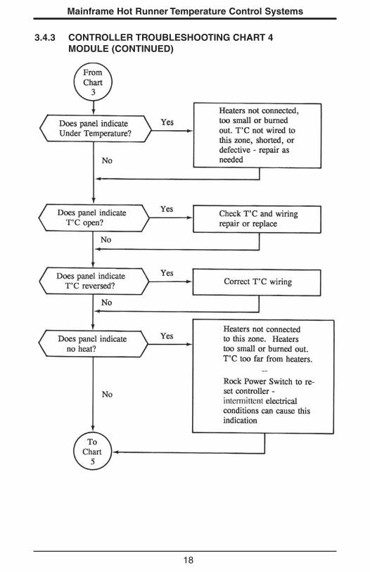
3.4.3 CONTROLLER TROUBLESHOOTING CHART 4MODULE (CONTINUED)
18

Mainframe Hot Runner Temperature Control Systems
19
3.4.3 CONTROLLER TROUBLESHOOTING CHART 5MODULE (CONTINUED)

900M205U00 Rev C
Two-Year Limited WarrantyTHIS EQUIPMENT IS WARRANTED TO BE FREE FROM DEFECTS OF MATERIAL ANDWORKMANSHIP. IT IS SOLD SUBJECT TO OUR MUTUAL AGREEMENT THAT THE LIABILITY OF THE MANUFACTURER IS TO REPLACE OR REPAIR THIS EQUIPMENT ATITS FACTORY, PROVIDED THAT IT IS RETURNED WITH TRANSPORTATION PREPAIDWITHIN TWO (2) YEARS OF ITS PURCHASE.
THE PURCHASER AGREES THAT THE MANUFACTURER ASSUMES NO LIABILITYUNDER ANY CIRCUMSTANCES FOR CONSEQUENTIAL DAMAGES RESULTING FROMITS USE OR FROM IMPROPER HANDLING OR PACKAGING OF SHIPMENTS RETURNEDTO THE FACTORY.
COMPONENTS WHICH WEAR OR WHICH ARE DAMAGED BY MISUSE ARE NOT WARRANTED. THESE INCLUDE CONTACT POINTS, FUSES, ELECTROMECHANICALRELAYS, AND TRIACS. UNITS WHICH HAVE BEEN MODIFIED BY A CUSTOMER IN ANYWAY ARE NOT WARRANTED.
Other than those expressly stated herein, THERE ARE NO OTHER WARRANTIES OF ANYKIND, EXPRESS OR IMPLIED, AND SPECIFICALLY EXCLUDED BUT NOT BY WAY OF LIMITATION, ARE THE IMPLIED WARRANTIES OF FITNESS FOR A PARTICULAR PURPOSE AND MERCHANTABILITY.
IT IS UNDERSTOOD AND AGREED THE SELLER’S LIABILITY WHETHER IN CONTRACT,IN TORT, UNDER ANY WARRANTY, IN NEGLIGENCE OR OTHERWISE SHALL NOTEXCEED THE RETURN OF THE AMOUNT OF THE PURCHASE PRICE PAID BY THE PURCHASER AND UNDER NO CIRCUMSTANCES SHALL SELLER BE LIABLE FORSPECIAL, INDIRECT, INCIDENTAL OR CONSEQUENTIAL DAMAGES. THE PRICE STATEDFOR THE EQUIPMENT IS A CONSIDERATION IN LIMITING SELLER’S LIABILITY. NOACTION, REGARDLESS OF FORM, ARISING OUT OF THE TRANSACTIONS OF THISAGREEMENT MAY BE BROUGHT BY PURCHASER MORE THAN ONE YEAR AFTER THECAUSE OF ACTION HAS ACCRUED.
SELLER’S MAXIMUM LIABILITY SHALL NOT EXCEED AND BUYER’S REMEDY IS LIMITED TO EITHER (i) REPAIR OR REPLACEMENT OF THE DEFECTIVE PART OR PRODUCT, OR AT SELLER’S OPTION (ii) RETURN OF THE PRODUCT AND REFUND OF THE PURCHASE PRICE, AND SUCH REMEDY SHALL BE BUYER’S ENTIRE ANDEXCLUSIVE REMEDY. THE SPECIFICATIONS PUT FORTH IN THIS MANUAL ARE SUBJECT TO CHANGE WITHOUT NOTICE.