92-24161-36 rev. 19 grk, grl and gtk two stage high
TRANSCRIPT
92-24161-36-19SUPERSEDES 92-24161-36-18
INSTALLATION INSTRUCTIONSFOR UPFLOW AND DOWNFLOW/HORIZONTALHIGH EFFICIENCY CONDENSINGTWO-STAGEGAS FURNACES(-)GRK, (-)GRL, AND (-)GTK SERIES
U.L. recognized fuel gas and CO (carbon monoxide) detectors are recommended in allapplications, and their installation should be in accordance with the manufacturer’srecommendations and/or local laws, rules, regulations, or customs.
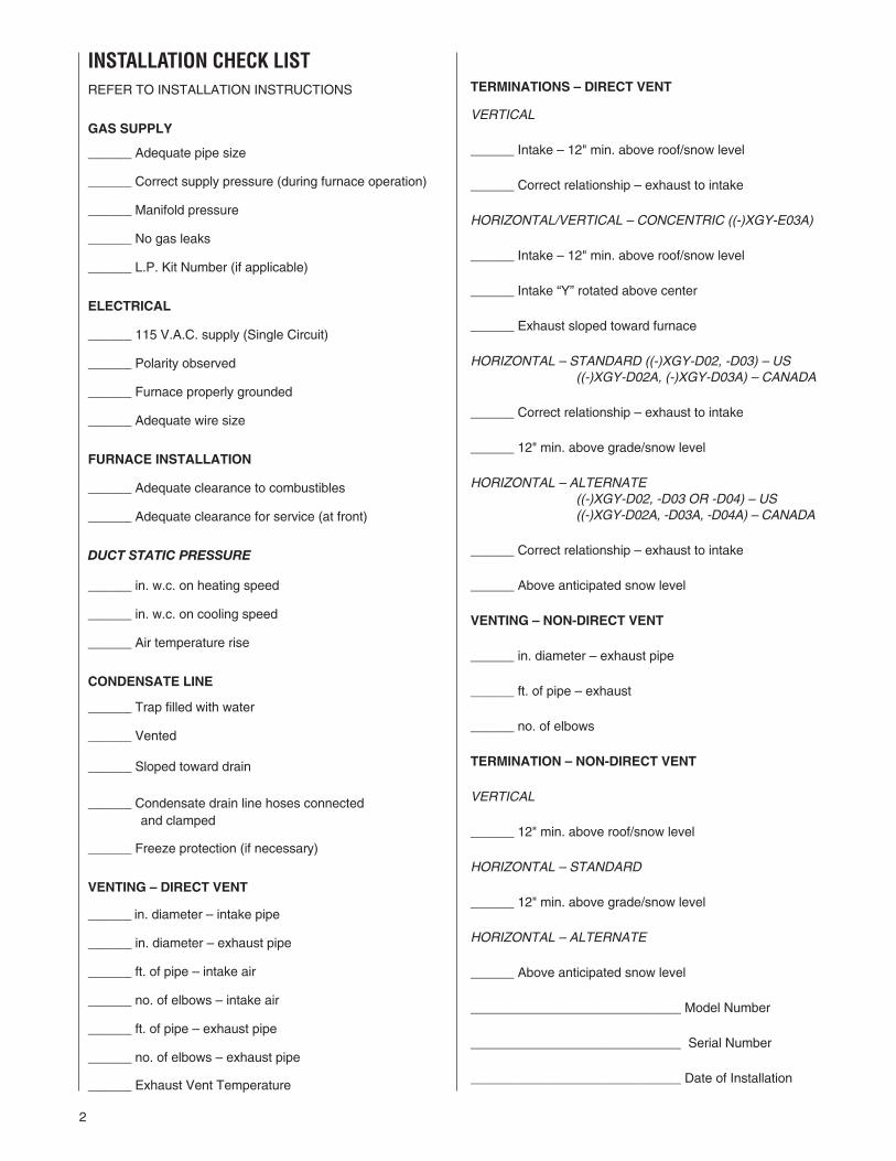
INSTALLATION CHECK LISTREFER TO INSTALLATION INSTRUCTIONS
GAS SUPPLY
______ Adequate pipe size
______ Correct supply pressure (during furnace operation)
______ Manifold pressure
______ No gas leaks
______ L.P. Kit Number (if applicable)
ELECTRICAL
______ 115 V.A.C. supply (Single Circuit)
______ Polarity observed
______ Furnace properly grounded
______ Adequate wire size
FURNACE INSTALLATION
______ Adequate clearance to combustibles
______ Adequate clearance for service (at front)
DUCT STATIC PRESSURE
______ in. w.c. on heating speed
______ in. w.c. on cooling speed
______ Air temperature rise
CONDENSATE LINE
______ Trap filled with water
______ Vented
______ Sloped toward drain
______ Condensate drain line hoses connectedand clamped
______ Freeze protection (if necessary)
VENTING – DIRECT VENT
______ in. diameter – intake pipe
______ in. diameter – exhaust pipe
______ ft. of pipe – intake air
______ no. of elbows – intake air
______ ft. of pipe – exhaust pipe
______ no. of elbows – exhaust pipe
______ Exhaust Vent Temperature
TERMINATIONS – DIRECT VENT
VERTICAL
______ Intake – 12" min. above roof/snow level
______ Correct relationship – exhaust to intake
HORIZONTAL/VERTICAL – CONCENTRIC ((-)XGY-E03A)
______ Intake – 12" min. above roof/snow level
______ Intake “Y” rotated above center
______ Exhaust sloped toward furnace
HORIZONTAL – STANDARD ((-)XGY-D02, -D03) – US((-)XGY-D02A, (-)XGY-D03A) – CANADA
______ Correct relationship – exhaust to intake
______ 12" min. above grade/snow level
HORIZONTAL – ALTERNATE((-)XGY-D02, -D03 OR -D04) – US((-)XGY-D02A, -D03A, -D04A) – CANADA
______ Correct relationship – exhaust to intake
______ Above anticipated snow level
VENTING – NON-DIRECT VENT
______ in. diameter – exhaust pipe
______ ft. of pipe – exhaust
______ no. of elbows
TERMINATION – NON-DIRECT VENT
VERTICAL
______ 12" min. above roof/snow level
HORIZONTAL – STANDARD
______ 12" min. above grade/snow level
HORIZONTAL – ALTERNATE
______ Above anticipated snow level
_____________________________ Model Number
_____________________________ Serial Number
_____________________________ Date of Installation
2
3
CONTENTS
Safety Precautions ...................................................................................................1
Installation Check List ..............................................................................................2
General Information..................................................................................................4
Safety Information ....................................................................................................6
Location Requirements and Considerations ............................................................8
Ducting ...................................................................................................................13
Venting and Combustion Air Piping .......................................................................15
Combustion and Ventilation Air..............................................................................17
Vent Pipe Installation..............................................................................................20
Condensate Drain/Neutralizer................................................................................33
Gas Supply and Piping...........................................................................................37
Electrical Wiring......................................................................................................42
Accessories ............................................................................................................43
Furnace Twinning...................................................................................................44
High Altitude Installations .......................................................................................48
Start-Up Procedures...............................................................................................51
Air Flow...................................................................................................................54
Maintenance...........................................................................................................57
Troubleshooting......................................................................................................59
Wiring Diagram.......................................................................................................62
IMPORTANT: All manufacturerproducts meet current Federal OSHAGuidelines for safety. CaliforniaProposition 65 warnings are requiredfor certain products, which are notcovered by the OSHA standards.
California's Proposition 65 requireswarnings for products sold in Californiathat contain, or produce, any of over600 listed chemicals known to the Stateof California to cause cancer or birthdefects such as fiberglass insulation,lead in brass, and combustion productsfrom natural gas.
All “new equipment” shipped for sale inCalifornia will have labels stating thatthe product contains and/or producesProposition 65 chemicals. Although wehave not changed our processes,having the same label on all ourproducts facilitates manufacturing andshipping. We cannot always know“when, or if” products will be sold in theCalifornia market.
You may receive inquiries fromcustomers about chemicals found in, orproduced by, some of our heating andair-conditioning equipment, or found innatural gas used with some of ourproducts. Listed below are thosechemicals and substances commonlyassociated with similar equipment inour industry and other manufacturers.
• Glass Wool (Fiberglass) Insulation• Carbon Monoxide (CO)• Formaldehyde• Benzene
More details are available at theWebsites for OSHA (OccupationalSafety and Health Administration), atwww.osha.gov and the State ofCalifornia's OEHHA (Office ofEnvironmental Health HazardAssessment), at www.oehha.org.Consumer education is important sincethe chemicals and substances on thelist are found in our daily lives. Mostconsumers are aware that productspresent safety and health risks, whenimproperly used, handled andmaintained.

NOTE: A load calculation must beperformed to properly determine therequired furnace BTU size for thestructure. Also, the duct must be properlydesigned and installed for proper airflow.Existing ductwork must be inspected forproper size and sealed system. Properairflow is necessary for both user comfortand equipment performance.Before opening the furnace carton andinstallation of the furnace, verify the datatags on the carton and inside thefurnace, match and is what was orderedfrom the local distributor. Also, check forany damage to the furnace beforeinstallation.IMPORTANT: Proper application,installation and maintenance of thisfurnace and system is a must ifconsumers are to receive the full benefitsfor which they have paid.The (-)GRK-, (-)GRL-, (-)GTK- seriesfurnaces are design-certified by CSA foruse with natural and propane gases as
4
follows:1. As non-direct vent central forced airfurnaces taking combustion air fromthe installation area or using airducted from the outside.
2. As direct vent central forced airfurnaces with all combustion airsupplied directly to the furnaceburners through a special air intakesystem outlined in theseinstructions.Install this furnace inaccordance with the AmericanNational Standard Z223.1 – latestedition entitled “National Fuel GasCode” (NFPA54) and requirementsor codes of the local utilities orother authorities having jurisdiction.This is available from the following:
National Fire ProtectionAssociation, Inc.
Batterymarch ParkQuincy, MA 02269
GENERAL INFORMATION
FIGURE 1UPFLOW FURNACE COMPONENTS
ITEMNO. PART NAME1 CONDENSATE TRAP2 DOOR SWITCH3 JUNCTION BOX4 TRANSFORMER5 PRESSURE SWITCHES6 EXHAUST TRANSITION7 CONNECTOR8 OUTLET AIR PIPE
9 SHIPPING PLUG (TO BE REMOVED)10 FLAME SENSOR11 OVERTEMPERATURE SWITCH12 TOP PLATE13 BURNER14 IGNITER15 COMBUSTION AIR INLET16 OPTIONAL AIR INLET (UPFLOW UNITS ONLY)17 OPTIONAL GAS INLET18 GAS VALVE
19 INDUCED DRAFT BLOWER20 CAPACITORS21 BLOWER22 LOW VOLTAGE TERMINAL23 CONTROL MOUNTING PLATE24 FILTER / SOLID METAL BASEPLATE (UPFLOWUNITS ONLY)25 BURNER COVER PLATE
(DOWNFLOW/HORIZONTAL UNITS ONLY)
NOTE: A PARTS BAG IS INCLUDED WITH THE FURNACE. IF A NEWPARTS BAG NEEDS TO BE ORDERED, USE THE FOLLOWING PARTNUMBERS: AS-100717-01 FOR (-)GRL-45, (-)GRL-60, (-)GRK-75, (-)GRL-90 AND (-)GRK-105 AS-100717-02 FOR (-)GRK-120
DOWNFLOW/HORIZONTAL FURNACE COMPONENTS
NOTE: A PARTS BAG IS INCLUDED WITH THE FURNACE. IF A NEWPARTS BAG NEEDS TO BE ORDERED, USE THE FOLLOWING PARTNUMBERS: AS-100717-03 FOR (-)GTK-60, (-)GTK-75, (-)GTK-90, (-)GTK-105 AND (-)GTK-120
AIRFLOW
9
8
4
17
1125
10
18
5
19
20
21
2
3 15 12 23 22
71
14613
AIRFLOW
CSA-INTERNATIONAL8501 East Pleasant Valley RoadCleveland, Ohio 44131-5575Install units in Canada in accordancewith CSA-B149, local installationcodes and authorities havingjurisdiction. CSA-B149 is availablefrom:CSA-INTERNATIONAL178 Rexdale Blvd.Toronto, OntarioCanada M9W, 1R3NOTE: It is our recommendation thatany HVAC equipment which weresubject to flooding be replaced toavoid any risk of property damage,personal injury or death. Also, ourposition that the immersion by floodwaters compromises any HVACproducts thus voiding this warranty.
5
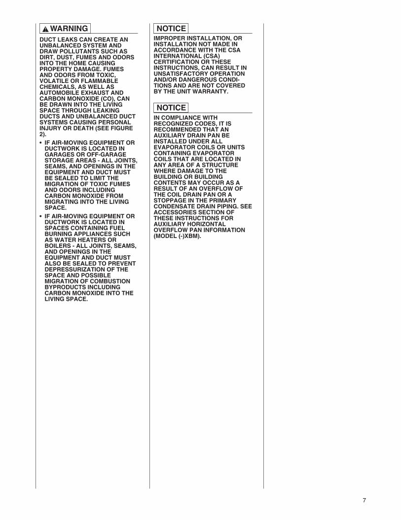
IMPROPER INSTALLATION, ORINSTALLATION NOT MADE INACCORDANCE WITH THE CSAINTERNATIONAL (CSA)CERTIFICATION OR THESEINSTRUCTIONS, CAN RESULT INUNSATISFACTORY OPERATIONAND/OR DANGEROUS CONDI-TIONS AND ARE NOT COVERED BYTHE UNIT WARRANTY.
IN COMPLIANCE WITHRECOGNIZED CODES, IT ISRECOMMENDED THAT ANAUXILIARY DRAIN PAN BEINSTALLED UNDER ALLEVAPORATOR COILS OR UNITSCONTAINING EVAPORATOR COILSTHAT ARE LOCATED IN ANY AREAOF A STRUCTURE WHERE DAMAGETO THE BUILDING OR BUILDINGCONTENTS MAY OCCUR AS ARESULT OF AN OVERFLOW OF THECOIL DRAIN PAN OR A STOPPAGEIN THE PRIMARY CONDENSATEDRAIN PIPING. SEE ACCESSORIESSECTION OF THESE INSTRUCTIONSFOR AUXILIARY HORIZONTALOVERFLOW PAN INFORMATION(MODEL (-)XBM).
RECEIVINGImmediately upon receipt, all cartonsand contents should be inspected fortransit damage. Units with damagedcartons should be opened immediately.If damage is found, it should be notedon the delivery papers, and a damageclaim filed with the last carrier.• After unit has been delivered to jobsite, remove carton taking care not todamage unit.
• Check the unit rating plate for unitsize, electric heat, coil, voltage,phase, etc. to be sure equipment
NOTICE
IMPORTANT INFORMATIONABOUT EFFICIENCY ANDINDOOR AIR QUALITYCentral cooling and heating equipmentis only as efficient as the duct systemthat carries the cooled or heated air. Tomaintain efficiency, comfort and goodindoor air quality, it is important to havethe proper balance between the airbeing supplied to each room and the airreturning to the cooling and heatingequipment.
Proper balance and sealing of the ductsystem improves the efficiency of theheating and air conditioning systemand improves the indoor air quality ofthe home by reducing the amount ofairborne pollutants that enter homesfrom spaces where the ductwork and /or equipment is located. Themanufacturer and the U.S.Environmental Protection Agency’sEnergy Star Program recommend thatcentral duct systems be checked by aqualified contractor for proper balanceand sealing.
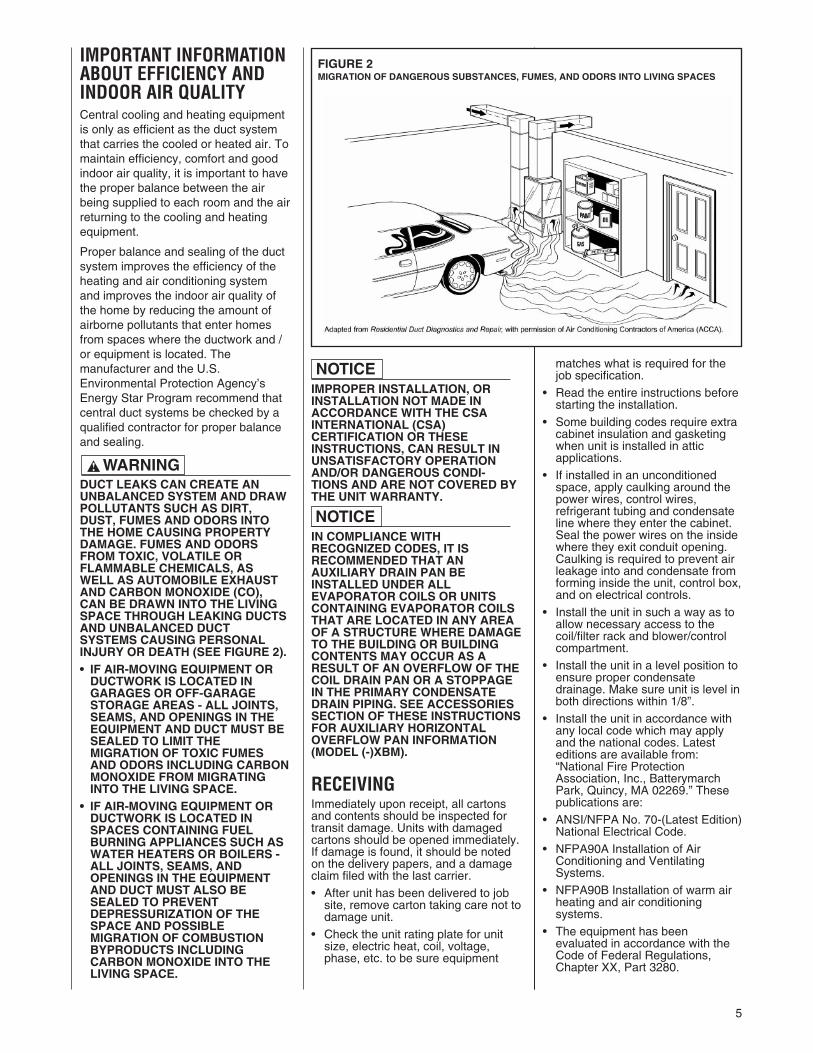
DUCT LEAKS CAN CREATE ANUNBALANCED SYSTEM AND DRAWPOLLUTANTS SUCH AS DIRT,DUST, FUMES AND ODORS INTOTHE HOME CAUSING PROPERTYDAMAGE. FUMES AND ODORSFROM TOXIC, VOLATILE ORFLAMMABLE CHEMICALS, ASWELL AS AUTOMOBILE EXHAUSTAND CARBON MONOXIDE (CO),CAN BE DRAWN INTO THE LIVINGSPACE THROUGH LEAKING DUCTSAND UNBALANCED DUCTSYSTEMS CAUSING PERSONALINJURY OR DEATH (SEE FIGURE 2).• IF AIR-MOVING EQUIPMENT ORDUCTWORK IS LOCATED INGARAGES OR OFF-GARAGESTORAGE AREAS - ALL JOINTS,SEAMS, AND OPENINGS IN THEEQUIPMENT AND DUCT MUST BESEALED TO LIMIT THEMIGRATION OF TOXIC FUMESAND ODORS INCLUDING CARBONMONOXIDE FROM MIGRATINGINTO THE LIVING SPACE.
• IF AIR-MOVING EQUIPMENT ORDUCTWORK IS LOCATED INSPACES CONTAINING FUELBURNING APPLIANCES SUCH ASWATER HEATERS OR BOILERS -ALL JOINTS, SEAMS, ANDOPENINGS IN THE EQUIPMENTAND DUCT MUST ALSO BESEALED TO PREVENTDEPRESSURIZATION OF THESPACE AND POSSIBLEMIGRATION OF COMBUSTIONBYPRODUCTS INCLUDINGCARBON MONOXIDE INTO THELIVING SPACE.
NOTICE
WARNING!
matches what is required for thejob specification.
• Read the entire instructions beforestarting the installation.
• Some building codes require extracabinet insulation and gasketingwhen unit is installed in atticapplications.
• If installed in an unconditionedspace, apply caulking around thepower wires, control wires,refrigerant tubing and condensateline where they enter the cabinet.Seal the power wires on the insidewhere they exit conduit opening.Caulking is required to prevent airleakage into and condensate fromforming inside the unit, control box,and on electrical controls.
• Install the unit in such a way as toallow necessary access to thecoil/filter rack and blower/controlcompartment.
• Install the unit in a level position toensure proper condensatedrainage. Make sure unit is level inboth directions within 1/8”.
• Install the unit in accordance withany local code which may applyand the national codes. Latesteditions are available from:“National Fire ProtectionAssociation, Inc., BatterymarchPark, Quincy, MA 02269.” Thesepublications are:
• ANSI/NFPA No. 70-(Latest Edition)National Electrical Code.
• NFPA90A Installation of AirConditioning and VentilatingSystems.
• NFPA90B Installation of warm airheating and air conditioningsystems.
• The equipment has beenevaluated in accordance with theCode of Federal Regulations,Chapter XX, Part 3280.
FIGURE 2MIGRATION OF DANGEROUS SUBSTANCES, FUMES, AND ODORS INTO LIVING SPACES
6
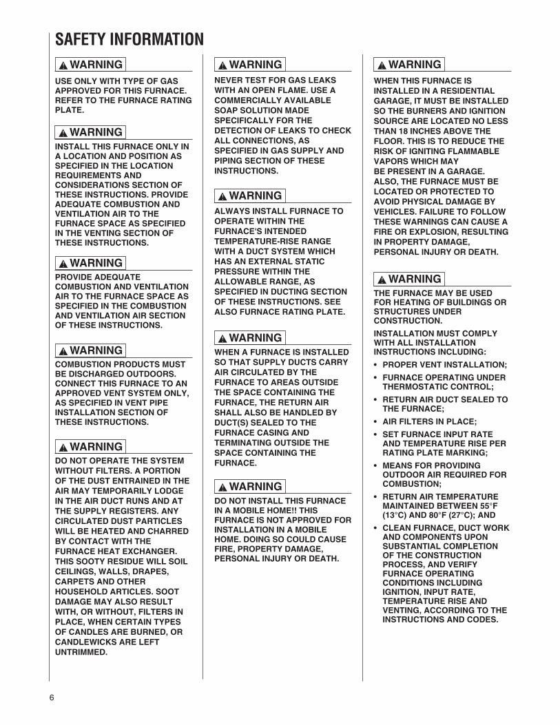
NEVER TEST FOR GAS LEAKSWITH AN OPEN FLAME. USE ACOMMERCIALLY AVAILABLESOAP SOLUTION MADESPECIFICALLY FOR THEDETECTION OF LEAKS TO CHECKALL CONNECTIONS, ASSPECIFIED IN GAS SUPPLY ANDPIPING SECTION OF THESEINSTRUCTIONS.
ALWAYS INSTALL FURNACE TOOPERATE WITHIN THEFURNACE'S INTENDEDTEMPERATURE-RISE RANGEWITH A DUCT SYSTEM WHICHHAS AN EXTERNAL STATICPRESSURE WITHIN THEALLOWABLE RANGE, ASSPECIFIED IN DUCTING SECTIONOF THESE INSTRUCTIONS. SEEALSO FURNACE RATING PLATE.
WHEN A FURNACE IS INSTALLEDSO THAT SUPPLY DUCTS CARRYAIR CIRCULATED BY THEFURNACE TO AREAS OUTSIDETHE SPACE CONTAINING THEFURNACE, THE RETURN AIRSHALL ALSO BE HANDLED BYDUCT(S) SEALED TO THEFURNACE CASING ANDTERMINATING OUTSIDE THESPACE CONTAINING THEFURNACE.
WHEN THIS FURNACE ISINSTALLED IN A RESIDENTIALGARAGE, IT MUST BE INSTALLEDSO THE BURNERS AND IGNITIONSOURCE ARE LOCATED NO LESSTHAN 18 INCHES ABOVE THEFLOOR. THIS IS TO REDUCE THERISK OF IGNITING FLAMMABLEVAPORS WHICH MAYBE PRESENT IN A GARAGE.ALSO, THE FURNACE MUST BELOCATED OR PROTECTED TOAVOID PHYSICAL DAMAGE BYVEHICLES. FAILURE TO FOLLOWTHESE WARNINGS CAN CAUSE AFIRE OR EXPLOSION, RESULTINGIN PROPERTY DAMAGE,PERSONAL INJURY OR DEATH.
THE FURNACE MAY BE USEDFOR HEATING OF BUILDINGS ORSTRUCTURES UNDERCONSTRUCTION.
INSTALLATION MUST COMPLYWITH ALL INSTALLATIONINSTRUCTIONS INCLUDING:
• PROPER VENT INSTALLATION;
• FURNACE OPERATING UNDERTHERMOSTATIC CONTROL;
• RETURN AIR DUCT SEALED TOTHE FURNACE;
• AIR FILTERS IN PLACE;
• SET FURNACE INPUT RATEAND TEMPERATURE RISE PERRATING PLATE MARKING;
• MEANS FOR PROVIDINGOUTDOOR AIR REQUIRED FORCOMBUSTION;
• RETURN AIR TEMPERATUREMAINTAINED BETWEEN 55°F(13°C) AND 80°F (27°C); AND
• CLEAN FURNACE, DUCT WORKAND COMPONENTS UPONSUBSTANTIAL COMPLETIONOF THE CONSTRUCTIONPROCESS, AND VERIFYFURNACE OPERATINGCONDITIONS INCLUDINGIGNITION, INPUT RATE,TEMPERATURE RISE ANDVENTING, ACCORDING TO THEINSTRUCTIONS AND CODES.
! WARNING
! WARNING
! WARNING
! WARNING
! WARNING
! WARNING
! WARNING
! WARNING
! WARNING
! WARNING
! WARNING
SAFETY INFORMATION
DO NOT OPERATE THE SYSTEMWITHOUT FILTERS. A PORTIONOF THE DUST ENTRAINED IN THEAIR MAY TEMPORARILY LODGEIN THE AIR DUCT RUNS AND ATTHE SUPPLY REGISTERS. ANYCIRCULATED DUST PARTICLESWILL BE HEATED AND CHARREDBY CONTACT WITH THEFURNACE HEAT EXCHANGER.THIS SOOTY RESIDUE WILL SOILCEILINGS, WALLS, DRAPES,CARPETS AND OTHERHOUSEHOLD ARTICLES. SOOTDAMAGE MAY ALSO RESULTWITH, OR WITHOUT, FILTERS INPLACE, WHEN CERTAIN TYPESOF CANDLES ARE BURNED, ORCANDLEWICKS ARE LEFTUNTRIMMED.
COMBUSTION PRODUCTS MUSTBE DISCHARGED OUTDOORS.CONNECT THIS FURNACE TO ANAPPROVED VENT SYSTEM ONLY,AS SPECIFIED IN VENT PIPEINSTALLATION SECTION OFTHESE INSTRUCTIONS.
PROVIDE ADEQUATECOMBUSTION AND VENTILATIONAIR TO THE FURNACE SPACE ASSPECIFIED IN THE COMBUSTIONAND VENTILATION AIR SECTIONOF THESE INSTRUCTIONS.
INSTALL THIS FURNACE ONLY INA LOCATION AND POSITION ASSPECIFIED IN THE LOCATIONREQUIREMENTS ANDCONSIDERATIONS SECTION OFTHESE INSTRUCTIONS. PROVIDEADEQUATE COMBUSTION ANDVENTILATION AIR TO THEFURNACE SPACE AS SPECIFIEDIN THE VENTING SECTION OFTHESE INSTRUCTIONS.
USE ONLY WITH TYPE OF GASAPPROVED FOR THIS FURNACE.REFER TO THE FURNACE RATINGPLATE.
DO NOT INSTALL THIS FURNACEIN A MOBILE HOME!! THISFURNACE IS NOT APPROVED FORINSTALLATION IN A MOBILEHOME. DOING SO COULD CAUSEFIRE, PROPERTY DAMAGE,PERSONAL INJURY OR DEATH.
7
DUCT LEAKS CAN CREATE ANUNBALANCED SYSTEM ANDDRAW POLLUTANTS SUCH ASDIRT, DUST, FUMES AND ODORSINTO THE HOME CAUSINGPROPERTY DAMAGE. FUMESAND ODORS FROM TOXIC,VOLATILE OR FLAMMABLECHEMICALS, AS WELL ASAUTOMOBILE EXHAUST ANDCARBON MONOXIDE (CO), CANBE DRAWN INTO THE LIVINGSPACE THROUGH LEAKINGDUCTS AND UNBALANCED DUCTSYSTEMS CAUSING PERSONALINJURY OR DEATH (SEE FIGURE2).• IF AIR-MOVING EQUIPMENT ORDUCTWORK IS LOCATED INGARAGES OR OFF-GARAGESTORAGE AREAS - ALL JOINTS,SEAMS, AND OPENINGS IN THEEQUIPMENT AND DUCT MUSTBE SEALED TO LIMIT THEMIGRATION OF TOXIC FUMESAND ODORS INCLUDINGCARBON MONOXIDE FROMMIGRATING INTO THE LIVINGSPACE.
• IF AIR-MOVING EQUIPMENT ORDUCTWORK IS LOCATED INSPACES CONTAINING FUELBURNING APPLIANCES SUCHAS WATER HEATERS ORBOILERS - ALL JOINTS, SEAMS,AND OPENINGS IN THEEQUIPMENT AND DUCT MUSTALSO BE SEALED TO PREVENTDEPRESSURIZATION OF THESPACE AND POSSIBLEMIGRATION OF COMBUSTIONBYPRODUCTS INCLUDINGCARBON MONOXIDE INTO THELIVING SPACE.
IMPROPER INSTALLATION, ORINSTALLATION NOT MADE INACCORDANCE WITH THE CSAINTERNATIONAL (CSA)CERTIFICATION OR THESEINSTRUCTIONS, CAN RESULT INUNSATISFACTORY OPERATIONAND/OR DANGEROUS CONDI-TIONS AND ARE NOT COVEREDBY THE UNIT WARRANTY.
IN COMPLIANCE WITHRECOGNIZED CODES, IT ISRECOMMENDED THAT ANAUXILIARY DRAIN PAN BEINSTALLED UNDER ALLEVAPORATOR COILS OR UNITSCONTAINING EVAPORATORCOILS THAT ARE LOCATED INANY AREA OF A STRUCTUREWHERE DAMAGE TO THEBUILDING OR BUILDINGCONTENTS MAY OCCUR AS ARESULT OF AN OVERFLOW OFTHE COIL DRAIN PAN OR ASTOPPAGE IN THE PRIMARYCONDENSATE DRAIN PIPING. SEEACCESSORIES SECTION OFTHESE INSTRUCTIONS FORAUXILIARY HORIZONTALOVERFLOW PAN INFORMATION(MODEL (-)XBM).
! WARNING NOTICE
NOTICE
8
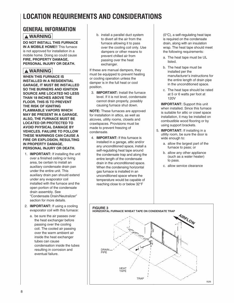
FIGURE 3HORIZONTAL FURNACE W/HEAT TAPE ON CONDENSATE TRAP
GENERAL INFORMATION
DO NOT INSTALL THIS FURNACEIN A MOBILE HOME!! This furnaceis not approved for installation in amobile home. Doing so could causeFIRE, PROPERTY DAMAGE,PERSONAL INJURY OR DEATH.
WHEN THIS FURNACE ISINSTALLED IN A RESIDENTIALGARAGE, IT MUST BE INSTALLEDSO THE BURNERS AND IGNITIONSOURCE ARE LOCATED NO LESSTHAN 18 INCHES ABOVE THEFLOOR. THIS IS TO PREVENTTHE RISK OF IGNITINGFLAMMABLE VAPORS WHICHMAY BE PRESENT IN A GARAGE.ALSO, THE FURNACE MUST BELOCATED OR PROTECTED TOAVOID PHYSICAL DAMAGE BYVEHICLES. FAILURE TO FOLLOWTHESE WARNINGS CAN CAUSE AFIRE OR EXPLOSION, RESULTINGIN PROPERTY DAMAGE,PERSONAL INJURY OR DEATH.
1. IMPORTANT: If installing the unitover a finished ceiling or livingarea, be certain to install anauxiliary condensate drain panunder the entire unit. Thisauxiliary drain pan should extendunder any evaporator coilinstalled with the furnace and theopen portion of the condensatedrain assembly. See“Condensate Drain/Neutralizer”section for more details.
2. IMPORTANT: If using a coolingevaporator coil with this furnace:
a. be sure the air passes overthe heat exchanger beforepassing over the coolingcoil. The cooled air passingover the warm ambient airinside the heat exchangertubes can causecondensation inside the tubesresulting in corrosion andeventual failure.
b. install a parallel duct systemto divert all the air from thefurnace allowing it to passover the cooling coil only. Usedampers or other means toprevent chilled air frompassing over the heatexchanger.
If these are manual dampers, theymust be equipped to prevent heatingor cooling operation unless thedamper is in the full heat or coolposition.
3. IMPORTANT: Install the furnacelevel. If it is not level, condensatecannot drain properly, possiblycausing furnace shut down.
NOTE: These furnaces are approvedfor installation in attics, as well asalcoves, utility rooms, closets andcrawlspaces. Provisions must bemade to prevent freezing ofcondensate.
4. IMPORTANT: If this furnace isinstalled in a garage, attic and/orany unconditioned space, install aself-regulating heat tape aroundthe condensate trap and along theentire length of the condensatedrain in the unconditioned space.When the condensing horizontalgas furnace is installed in anunconditioned space where thetemperature would be capable ofreaching close to or below 32°F
! WARNING
! WARNING
(0°C), a self-regulating heat tapeis required on the condensatedrain, along with an insulationwrap. The heat tape should meetthe following requirements:
a. The heat tape must be ULlisted.
b. The heat tape must beinstalled per themanufacturer’s instructions forthe entire length of drain pipein the unconditioned space.
c. The heat tape should be ratedat 5 or 6 watts per foot at120V
IMPORTANT: Support this unitwhen installed. Since this furnaceis suitable for attic or crawl spaceinstallation, it may be installed oncombustible wood flooring or byusing support brackets.
5. IMPORTANT: If installing in autility room, be sure the door iswide enough to:
a. allow the largest part of thefurnace to pass; or
b. allow any other appliance(such as a water heater)to pass.
c. allow service clearance
LOCATION REQUIREMENTS AND CONSIDERATIONS
I526
DRAINPIPE
HEATTAPE
TRAP
AIRFLOW

9
Upflow furnaces are shipped with abottom closure panel installed.When bottom return air is used,remove the panel by removing thetwo screws attaching the panel tothe front base angle. See filtersection for details.
COMBUSTIBLE MATERIAL MUSTNOT BE PLACED ON OR AGAINSTTHE FURNACE JACKET. THEAREA AROUND THE FURNACEMUST BE KEPT CLEAR AND FREEOF ALL COMBUSTIBLEMATERIALS INCLUDINGGASOLINE AND OTHERFLAMMABLE VAPORS ANDLIQUIDS. PLACEMENT OFCOMBUSTIBLE MATERIALS ON,AGAINST OR AROUND THEFURNACE JACKET CAN CAUSEAN EXPLOSION OR FIRERESULTING IN PROPERTYDAMAGE, PERSONAL INJURY ORDEATH. THE HOMEOWNERSHOULD BE CAUTIONED THATTHE FURNACE AREA MUST NOTBE USED AS A BROOM CLOSETOR FOR ANY OTHER STORAGEPURPOSES.
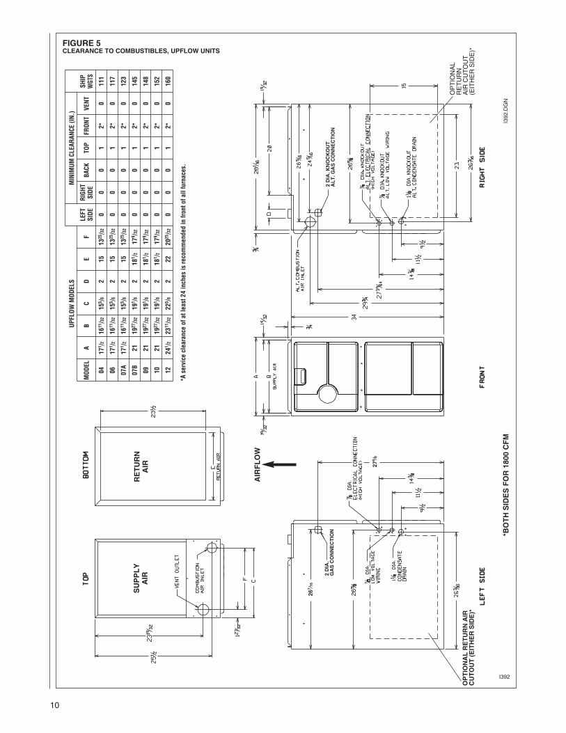
CLEARANCE -ACCESSIBILITYThe design of forced air furnaces withinput ratings as listed in the tableunder Figure 5 are certified by CSA-International for the clearances tocombustible materials shown ininches.
See name/rating plate and clearancelabel for specific model number andclearance information.
Service clearance of at least 24inches is recommended in front ofall furnaces.
NOTE: Use recommended 24”clearance if accessibility clearancesare greater than fire protectionclearances.
UPFLOW FURNACES ARE DESIGN-CERTIFIED FOR INSTALLATIONON COMBUSTIBLE FLOORS.NOTE, HOWEVER, THATFURNACES MUST NOT BEINSTALLED DIRECTLY ONCARPETING, TILE OR OTHERCOMBUSTIBLE MATERIAL OTHERTHAN WOOD FLOORING.INSTALLATION ON ACOMBUSTIBLE MATERIAL CANRESULT IN FIRE, CAUSINGPROPERTY DAMAGE, PERSONALINJURY OR DEATH.
! WARNING
THIS FURNACE IS NOTAPPROVED OR RECOMMENDEDFOR INSTALLATION ON ITS BACK,WITH ACCESS DOORS FACINGUPWARDS OR IN ANYHORIZONTAL CONFIGURATION.
SITE SELECTION1. Select a site in the building near
the center of the proposed, orexisting, duct system.
2. Give consideration to the ventsystem piping when selecting thefurnace location. Be sure theventing system can get from thefurnace to the termination withminimal length and elbows.
3. Locate the furnace near theexisting gas piping. Or, if runninga new gas line, locate thefurnace to minimize the lengthand elbows in the gas piping.
4. Locate the furnace to maintainproper clearance to combustiblesas shown in the following tables.
DO NOT LIFT THE UNIT BY THEHEAT EXCHANGER TUBES.DOING SO CAN DAMAGE THEHEAT EXCHANGER ASSEMBLY.
! WARNING
CAUTION!
! WARNING
FIGURE 4HORIZONTAL FURNACE INSTALLED W/SUPPORT BRACKETS
GASPIPE
TRAP
EXHAUSTFAN
ELECTRICALCONDUIT
INTAKEVENT
I522
AIRFLOW
NOTE: Do not block furnace access with support rods. Maintain clearances recommended in Figure7. Allow enough space for proper service maintenance or replacement of the heat exchanger andblower assembly.
10
FIGURE 5CLEARANCE TO COMBUSTIBLES, UPFLOW UNITS
I392
UPF
LOW
MODELS
MINIM
UM
CLEA
RAN
CE(IN.)
LEFT
RIGHT
SHIP
MODEL
AB
CD
EF
SIDE
SIDE
BACK
TOP
FRONT
VENT
WGT
S
0417
1 /2
1611/32
155 /8
215
1325/32
00
01
2*0
111
0617
1 /2
1611/32
155 /8
215
1325/32
00
01
2*0
117
07A
171 /2
1611/32
155 /8
215
1325/32
00
01
2*0
123
07B
2119
27/32
191 /8
218
1 /2
179 /32
00
01
2*0
145
0921
1927/32
191 /8
218
1 /2
179 /32
00
01
2*0
148
1021
1927/32
191 /8
218
1 /2
179 /32
00
01
2*0
152
1224
1 /2
2311/32
225 /8
222
2025/32
00
01
2*0
160
*Aserviceclearanceof
atleast2
4inches
isrecommendedin
fronto
fallfurnaces.
SUPPLY
AIR
RETURN
AIR
AIRFLOW
OPTIONALRETURNAIR
CUTOUT(EITHERSIDE)*
*BOTHSIDESFOR1800CFM
OPTIONAL
RETURN
AIRCUTOUT
(EITHERSIDE)*
I392.DGN
2DIA.KNOCKOUT
ALT.GASCONNECTION
267 ⁄16
275 ⁄8
2DIA.
GASCONNECTION
11
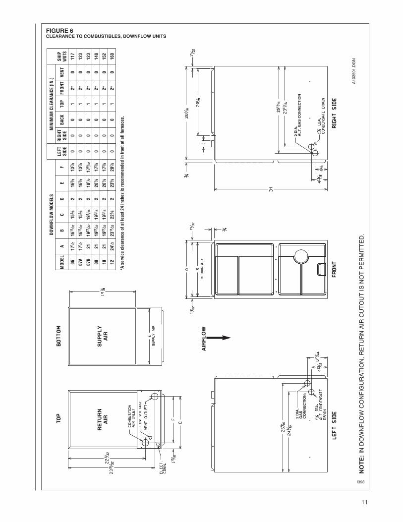
FIGURE 6CLEARANCE TO COMBUSTIBLES, DOWNFLOW UNITS
I393
DOWNFLOW
MODELS
MINIM
UM
CLEA
RAN
CE(IN.)
LEFT
RIGHT
SHIP
MODEL
AB
CD
EF
SIDE
SIDE
BACK
TOP
FRONT
VENT
WGT
S
0617
1 ⁄216
11⁄32
155 ⁄8
216
5 ⁄813
7 ⁄80
00
12*
0117
07A
171 ⁄2
1611⁄32
155 ⁄8
216
5 ⁄813
7 ⁄80
00
12*
0123
07B
2119
27/32
193 /16
218
1 /2
179 /32
00
01
2*0
123
0921
1927⁄32
193 ⁄1
62
201 ⁄8
173 ⁄8
00
01
2*0
148
1021
1927⁄32
193 ⁄1
62
201 ⁄8
173 ⁄8
00
01
2*0
152
1224
1 ⁄223
11⁄32
225 ⁄8
223
5 ⁄820
7 ⁄80
00
12*
0160
*Aserviceclearanceof
atleast2
4inches
isrecommendedin
fronto
fallfurnaces.
NOTE:INDOWNFLOWCONFIGURATION,RETURNAIRCUTOUTISNOTPERMITTED.
AIRFLOW
SUPPLY
AIR
RETURN
AIR
A103501.DGN
2DIA.
ALT.GASCONNECTION
2513⁄16
43⁄8
2DIA.
GAS
CONNECTION
12
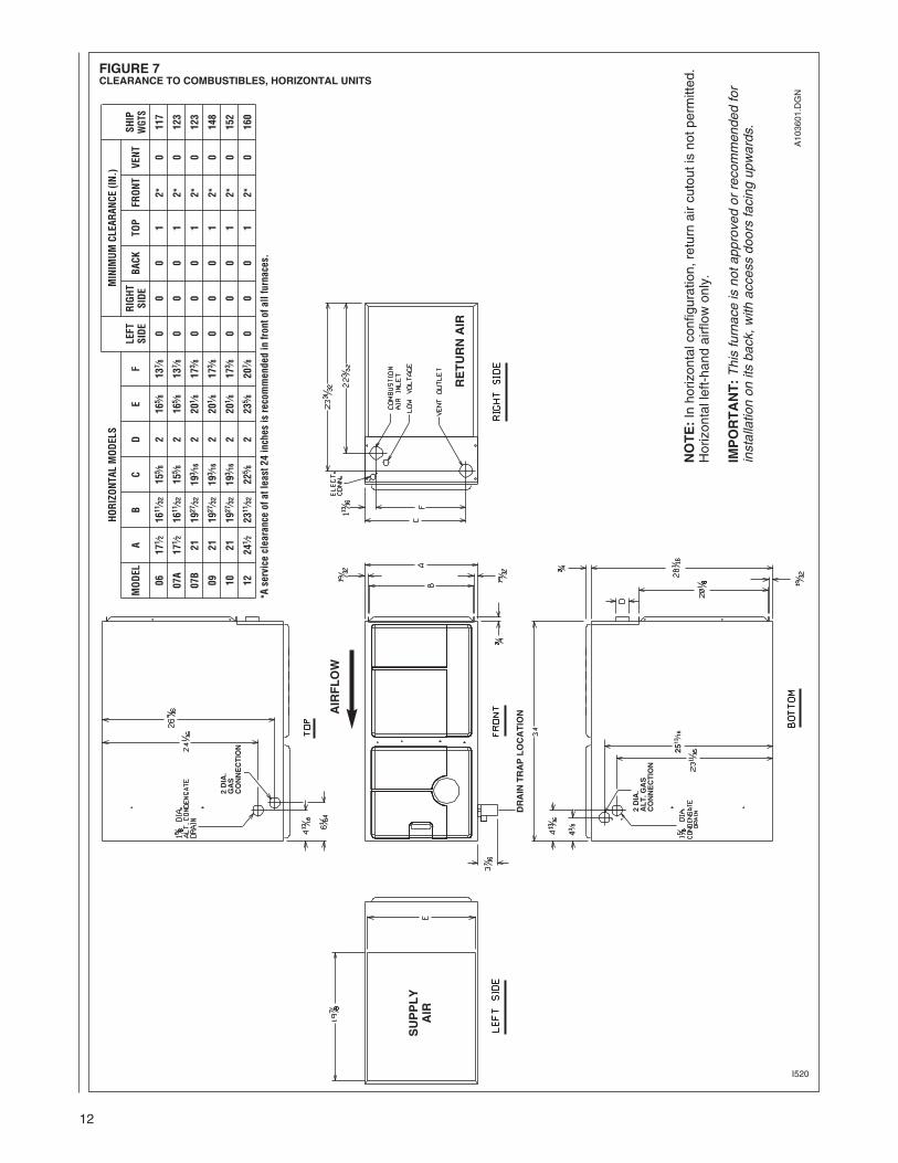
FIGURE 7CLEARANCE TO COMBUSTIBLES, HORIZONTAL UNITS
I520
HORIZONTA
LMODELS
MINIM
UM
CLEA
RAN
CE(IN.)
LEFT
RIGHT
SHIP
MODEL
AB
CD
EF
SIDE
SIDE
BACK
TOP
FRONT
VENT
WGT
S
0617
1 ⁄216
11⁄32
155 ⁄8
216
5 ⁄813
7 ⁄80
00
12*
0117
07A
171 ⁄2
1611⁄32
155 ⁄8
216
5 ⁄813
7 ⁄80
00
12*
0123
07B
2119
27⁄32
193 ⁄1
62
201 ⁄8
173 ⁄8
00
01
2*0
123
0921
1927⁄32
193 ⁄1
62
201 ⁄8
173 ⁄8
00
01
2*0
148
1021
1927⁄32
193 ⁄1
62
201 ⁄8
173 ⁄8
00
01
2*0
152
1224
1 ⁄223
11⁄32
225 ⁄8
223
5 ⁄820
7 ⁄80
00
12*
0160
*Aserviceclearanceof
atleast2
4inches
isrecommendedin
fronto
fallfurnaces.
NOTE:Inhorizontalconfiguration,returnaircutoutisnotpermitted.
Horizontalleft-handairflowonly.
IMPORTANT:Thisfurnaceisnotapprovedorrecommendedfor
installationonitsback,withaccessdoorsfacingupwards.
AIRFLOW
DRAINTRAPLOCATION
SUPPLY
AIR
RETURNAIR
A103601.DGN
2DIA.
GAS
CONNECTION
2DIA.
ALT.GAS
CONNECTION
43⁄8
2513⁄16
1313
DUCTINGProper air flow is required for thecorrect operation of this furnace.Too little air flow can cause erraticoperation and can damage the heatexchanger. The duct system mustcarry the correct amount of air forheating and cooling if summer airconditioning is used.
Size the ducts according toacceptable industry standards andmethods. The total static pressuredrop of the air distribution systemshould not exceed 0.5" w.c.
NEVER ALLOW THE PRODUCTSOF COMBUSTION FROM THEFLUE TO ENTER THE RETURN AIRDUCTWORK OR THE CIRCULATEDAIR SUPPLY. ALL RETURNDUCTWORK MUST BEADEQUATELY SEALED ANDSECURED TO THE FURNACEWITH SHEET METAL SCREWS;AND JOINTS, TAPED. ALL OTHERDUCT JOINTS MUST BE SECUREDWITH APPROVED CONNECTIONSAND SEALED AIRTIGHT. WHENAN UPFLOW FURNACE ISMOUNTED ON A PLATFORM WITHRETURN THROUGH THE BOTTOM,IT MUST BE SEALED AIRTIGHTBETWEEN THE FURNACE ANDTHE RETURN AIR PLENUM. THEFLOOR OR PLATFORM MUSTPROVIDE SOUND PHYSICALSUPPORT OF THE FURNACEWITHOUT SAGGING, CRACKS, ORGAPS, AROUND THE BASE,PROVIDING A SEAL BETWEENTHE SUPPORT AND THE BASE.
FAILURE TO PREVENTPRODUCTS OF COMBUSTIONFROM BEING CIRCULATED INTOTHE LIVING SPACE CAN CREATEPOTENTIALLY HAZARDOUSCONDITIONS, INCLUDINGCARBON MONOXIDE POISONINGTHAT COULD RESULT INPERSONAL INJURY OR DEATH.
DO NOT, UNDER ANYCIRCUMSTANCES, CONNECTRETURN OR SUPPLY DUCTWORKTO OR FROM ANY OTHER HEATPRODUCING DEVICE SUCH AS AFIREPLACE INSERT, STOVE, ETC.DOING SO MAY RESULT IN FIRE,CARBON MONOXIDE POISONING,EXPLOSION, PERSONAL INJURYOR PROPERTY DAMAGE.
IMPORTANT: Some high efficiencyfilters have a greater than normalresistance to air flow. This canadversely affect furnace operation.BE SURE TO CHECK AIR FLOW.
IMPORTANT:When using outside air,design and adjust the system to maintaina return air temperature ABOVE 55° Fduring the heating season.
NOTE: Return air grilles and warm airregisters must not be obstructed orclosed.
UPFLOW UNITS1. Position the unit to minimize long
runs of duct or runs of duct withmany turns and elbows.
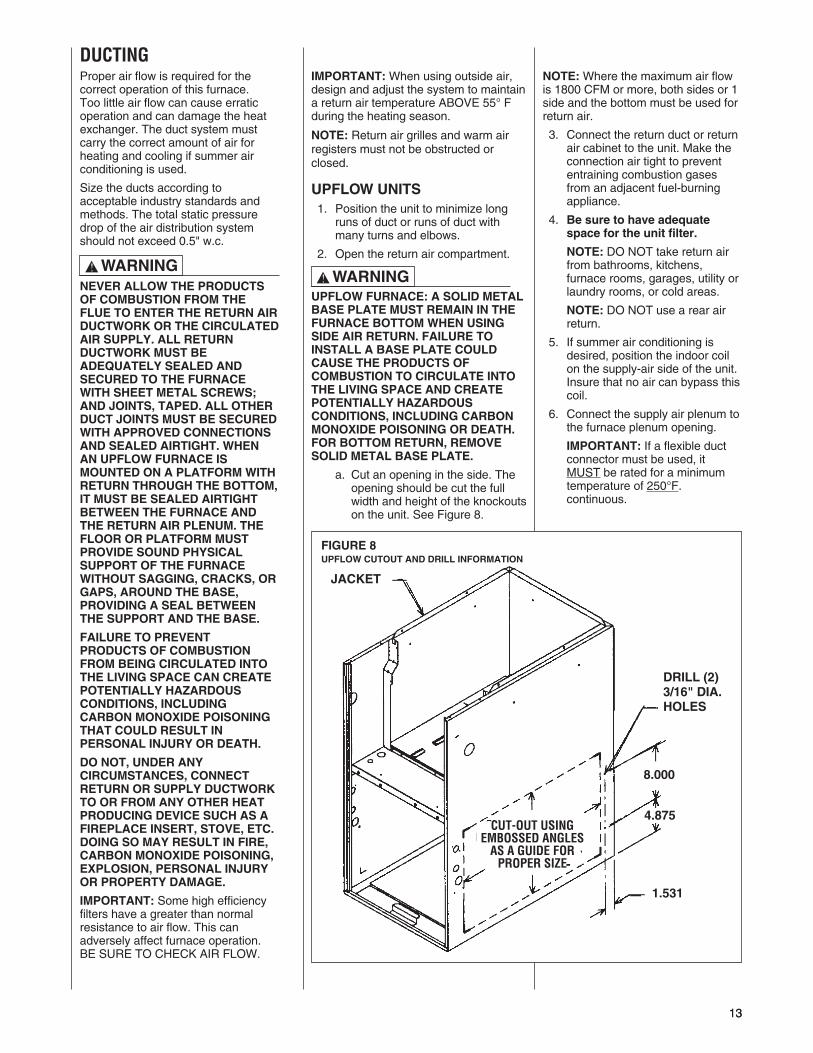
2. Open the return air compartment.
UPFLOW FURNACE: A SOLID METALBASE PLATE MUST REMAIN IN THEFURNACE BOTTOM WHEN USINGSIDE AIR RETURN. FAILURE TOINSTALL A BASE PLATE COULDCAUSE THE PRODUCTS OFCOMBUSTION TO CIRCULATE INTOTHE LIVING SPACE AND CREATEPOTENTIALLY HAZARDOUSCONDITIONS, INCLUDING CARBONMONOXIDE POISONING OR DEATH.FOR BOTTOM RETURN, REMOVESOLID METAL BASE PLATE.
a. Cut an opening in the side. Theopening should be cut the fullwidth and height of the knockoutson the unit. See Figure 8.
NOTE:Where the maximum air flowis 1800 CFM or more, both sides or 1side and the bottom must be used forreturn air.
3. Connect the return duct or returnair cabinet to the unit. Make theconnection air tight to prevententraining combustion gasesfrom an adjacent fuel-burningappliance.
4. Be sure to have adequatespace for the unit filter.
NOTE: DO NOT take return airfrom bathrooms, kitchens,furnace rooms, garages, utility orlaundry rooms, or cold areas.
NOTE: DO NOT use a rear airreturn.
5. If summer air conditioning isdesired, position the indoor coilon the supply-air side of the unit.Insure that no air can bypass thiscoil.
6. Connect the supply air plenum tothe furnace plenum opening.
IMPORTANT: If a flexible ductconnector must be used, itMUST be rated for a minimumtemperature of 250°F.continuous.
! WARNING
FIGURE 8UPFLOW CUTOUT AND DRILL INFORMATION
JACKET
DRILL (2)3/16" DIA.HOLES
8.000
4.875
1.531
! WARNING
14
DOWNFLOW UNITS1. Position the unit to minimize long
runs of duct or runs of duct withmany turns and elbows.
2. If summer air conditioning isdesired, position the indoor coilon the supply-air side of the unit.Insure that no air can bypass thiscoil.
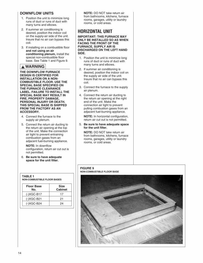
3. If installing on a combustible floorand not using an airconditioning plenum, install thespecial non-combustible floorbase. See Table 1 and Figure 9.
THE DOWNFLOW FURNACEDESIGN IS CERTIFIED FORINSTALLATION ON A NON-COMBUSTIBLE FLOOR. USE THESPECIAL BASE SPECIFIED ONTHE FURNACE CLEARANCELABEL. FAILURE TO INSTALL THESPECIAL BASE MAY RESULT INFIRE, PROPERTY DAMAGE,PERSONAL INJURY OR DEATH.THIS SPECIAL BASE IS SHIPPEDFROM THE FACTORY AS ANACCESSORY.
4. Connect the furnace to thesupply air plenum.
5. Connect the return air ducting tothe return air opening at the topof the unit. Make the connectionair tight to prevent entrainingcombustion gases from anadjacent fuel-burning appliance.
NOTE: In downflowconfiguration, return air cut out isnot permitted.
6. Be sure to have adequatespace for the unit filter.
NOTE: DO NOT take return airfrom bathrooms, kitchens, furnacerooms, garages, utility or laundryrooms, or cold areas.
HORIZONTAL UNITIMPORTANT: THIS FURNACE MAYONLY BE INSTALLED SO AS WHENFACING THE FRONT OF THEFURNACE, SUPPLY AIR ISDISCHARGED ON THE LEFT HANDSIDE.
1. Position the unit to minimize longruns of duct or runs of duct withmany turns and elbows.
2. If summer air conditioning isdesired, position the indoor coil onthe supply air side of the unit.Insure that no air can bypass thiscoil.
3. Connect the furnace to the supplyair plenum.
4. Connect the return air ducting tothe return air opening at the rightend of the unit. Make theconnection air tight to preventpulling combustion gases from anadjacent fuel-burning appliance.
NOTE: In horizontal configuration,return air cut out is not permitted.
5. Be sure to have adequate spacefor the unit filter.
NOTE: DO NOT take return airfrom bathrooms, kitchens, furnacerooms, garages, utility or laundryrooms, or cold areas.
! WARNING
FIGURE 9NON-COMBUSTIBLE FLOOR BASE
TABLE 1NON-COMBUSTIBLE FLOOR BASES
Floor Base SizeNo. Cabinet
(-)XGC-B17 17
(-)XGC-B21 21
(-)XGC-B24 24

15
GENERAL INFORMATION
READ AND FOLLOW ALLINSTRUCTIONS IN THIS SECTION.FAILURE TO PROPERLY VENTTHIS FURNACE CAN CAUSECARBON MONOXIDE POISONINGOR AN EXPLOSION OR FIRE,RESULTING IN PROPERTYDAMAGE, PERSONAL INJURYOR DEATH.
This furnace removes both sensibleand latent heat from the combustionflue gases. Removal of latent heatresults in condensation of flue gaswater vapor. This condensed watervapor drains from the secondary heatexchanger and out of the unit into adrain trap.
When installed as a non-direct ventfurnace, only exhaust piping isrequired and inside combustion airmay be used. Refer to section on“COMBUSTION & VENTILATION AIRFOR FURNACE INSTALLATIONS.”
Direct vent installations require adedicated combustion air and ventingsystem. All air for combustion is takenfrom the outside atmosphere and allcombustion products are dischargedto the outdoors.
The combustion air and vent pipefittings must conform to AmericanNational Standards Institute (ANSI)and American Society for TestingMaterials (ASTM) standardsD1785 (Schedule 40 PVC), D2665(PVC-DWV), D2241 (SDR-21 andSDR26-26 PVC), D2661 (ABS-DWV)or F628 (Schedule 40 ABS-DWV).
IN CANADA, PRODUCTSCERTIFIED FOR INSTALLATIONAND INTENDED TO BE VENTEDWITH PLASTIC VENT SYSTEMS(PVC, CPVC) MUST USE VENTSYSTEMS THAT ARE CERTIFIEDTO THE STANDARD FOR TYPE BHGAS VENTING SYSTEMS, ULCS636.THE COMPONENTS OF THECERTIFIED MATERIAL MUST NOTBE INTERCHANGEDWITH OTHERVENT SYSTEMS OR UNLISTEDPIPE/FITTINGS.PLASTIC COMPONENTS ANDSPECIFIED PRIMERS AND GLUESOF THE CERTIFIED SYSTEM MUSTBE FROM A SINGLE SYSTEMMANUFACTURER AND NOTINTERMIXED WITH OTHERSYSTEM MANUFACTURER’SPARTS.NOTE: INLET AIR PIPING IS NOTCONSIDERED TO BE A PART OFTHE “VENTING SYSTEM”. THE
REQUIREMENT THAT VENTMATERIAL BE CERTIFIED TO ULCS636 DOES NOT APPLY TO INLETAIR PIPING. VENT TERMINATIONSAND CONCENTRIC TERMINATIONSMUST BE APPROVED BY THEMANUFACTURER AND CERTIFIEDULC-636.
IMPORTANT: The plastic combustionair and venting components are ofSchedule 40 PVC. If using ABSpiping, ensure that the solventcement is compatible for joining PVCto ABS components or use amechanical connection that canwithstand the vent temperatures andare corrosion resistant.
NOTE: Schedule 40 ABS-DWV pipeand fittings may be used as analternate to PVC pipe for thecombustion air inlet and vent pipes.
NOTE: Cellular core PVC is alsoapproved for use. It must be schedule40PVC-DWV cellular pipe for non-pressure applications andmanufactured under ASTM F-891.
NOTE:With the furnace correctlyvented, the inducer will moveapproximately 25 cfm per 100,000Btu’s.
IMPORTANT: No part of thecombustion air and vent pipes mayrun under ground.
OVERTEMPERATURESAFETY SWITCHESFurnaces are equipped with safetyswitches in the control compartmentto protect against overtemperatureconditions caused by inadequatecombustion air supply. The switchesare located in the burnercompartment. If a switch is tripped itmust be manually reset.
DO NOT JUMPER THESEDEVICES! IF ONE OF THESESWITCHES SHOULD TRIP, AQUALIFIED INSTALLER, SERVICEAGENCY OR THE GAS SUPPLIERMUST BE CALLED TO CHECKAND/OR CORRECT FORADEQUATE COMBUSTION AIRSUPPLY. DO NOT RESET THESWITCHES WITHOUT TAKINGCORRECTIVE ACTION TO ASSURETHAT AN ADEQUATE SUPPLY OFCOMBUSTION AIR IS MAINTAINEDUNDER ALL CONDITIONS OFOPERATION. FAILURE TO DO SOCAN RESULT IN CARBONMONOXIDE POISONING ORDEATH. IF THIS UNIT IS MOUNTEDIN A CLOSET, THE DOOR MUSTBE CLOSED WHEN MAKING THISCHECK.
REPLACE THESE SWITCHESONLY WITH THE IDENTICALREPLACEMENT PART.
EXISTING VENT SYSTEMSWhen the installation of this furnacereplaces an existing furnace that isremoved from a vent system servingother appliances, the vent system islikely to be too large to properly ventthe remaining attached appliances.The following steps should befollowed with each applianceremaining connected to the originalcommon vent system. Place theappliance to be tested in operation,while the other appliances remainingconnected to the common ventsystem are not in operation. Test theoperation of each applianceindividually by the following method.1. Permanently seal any unused
openings in the common ventingsystem.
2. Visually inspect the ventingsystem for proper size andhorizontal pitch and determinethat there is no blockage,restriction, leakage, corrosion orother deficiencies which couldcause an unsafe condition.
3. If practical, close all buildingdoors, windows and all doorsbetween the space where theappliances remaining connectedto the common venting systemare located.Turn on clothes dryers and anyappliance not connected to thecommon venting system. Turn onany exhaust fans, such as rangehoods and bathroom exhausts,so they will operate at maximumspeed. Do not operate a summerexhaust fan. Close fireplacedampers.
4. Follow the lighting instructions.Place the appliance beinginspected into operation. Adjustthe thermostat so the appliancewill operate continuously.
5. Test for spillage at the draft hoodrelief opening after 5 minutes ofmain burner operation. Use theflame of a match or candle, orsmoke from a cigarette, cigaror pipe.
VENTING AND COMBUSTION AIR PIPING
! WARNING
! WARNING
! WARNING

16
1. Cut pipe end square. Chamferedge of pipe. Clean fitting socketand pipe joint area of all dirt,grease and moisture.
2. After checking pipe and socketfor proper fit, wipe socket andpipe with cleaner-primer. Applya liberal coat of primer to insidesurface of socket and outside ofpipe. Read instructions includedwith the primer for properapplication.
3. Apply a thin coat of cementevenly in the socket. Quicklyapply a heavy coat of cement tothe pipe end and insert pipe intofitting with a slight twistingmovement until it bottoms out.NOTE: Cement must be fluid; ifnot, recoat.
4. Hold the pipe in the fitting for 30seconds to prevent the taperedsocket from pushing the pipe outof the fitting.
5. Wipe all excess cement from thejoint with a rag. Allow 15 minutesbefore handling. Cure time variesaccording to fit, temperature andhumidity.
NOTE: Stir the solvent cementfrequently while using. Use a naturalbristle brush or the dauber suppliedwith the can. The proper brush size isone inch.IMPORTANT: For Proper InstallationDO NOT use solvent cement thathas become curdled, lumpy orthickened.DO NOT thin. Observe shelfprecautions printed on containers.For application below 32°F, use onlylow-temperature-type solventcement.
6. After it has been determined thateach appliance that remainsconnected to the commonventing system properly vents(when tested as outlined above),return doors, windows, exhaustfans, fireplace dampers and anyother gas-burning appliance totheir previous conditions of use.
7. If improper venting is observedduring any of the above tests, thecommon venting system must beresized.
When the furnace is installed in thesame space with other gasappliances such as a water heater, besure there is an adequate supply ofcombustion and ventilation air for theother appliances. Do not delete orreduce the combustion air supplyrequired by the other gas appliancesin this space. See Z223.1, NationalFuel Gas Code (NFPA54) fordetermining the combustion airrequirements for gas appliances. Anunconfined space must have at least50 cubic feet (volume) for each1,000 BTUH of the total input of allappliances in the space. If the openspace containing the appliances is ina building with tight construction(contemporary construction), outsideair may still be required for theappliances to burn and vent properly.Outside air openings should be sizedthe same as for a confined space.IMPORTANT: Only the current ventinstructions apply. All 90 Plus GasFurnaces cannot be common vented.
JOINING PIPE ANDFITTINGS
PVC SOLVENT CEMENTS ANDPRIMERS ARE HIGHLYFLAMMABLE. PROVIDEADEQUATE VENTILATION AND DONOT ASSEMBLE NEAR HEATSOURCE OR AN OPEN FLAME. DONOT SMOKE. AVOID SKIN OR EYECONTACT. OBSERVE ALLCAUTIONS AND WARNINGSPRINTED ON MATERIALCONTAINERS. FAILURE TOFOLLOW THESE GUIDELINESMAY RESULT IN FIRE, EXPLOSIONOR ASPHYXIATION CAUSINGPERSONAL INJURY OR DEATH.All pipe, fittings, solvent cement,primers and procedures mustconform to American NationalStandard Institute and AmericanSociety for Testing and Materials(ANSI/ASTM) standards as shownbelow:
CEMENTING JOINTSProperly seal all joints in the PVCvent using the following materials andprocedures.PVC CLEANER-PRIMER ANDPVC MEDIUM-BODY SOLVENTCEMENTIMPORTANT: After cutting pipe,remove all ragged edges and burrs.This is important to prevent reductionin pressure drop throughout thesystem.
! WARNING
PIPE & FITTING MATERIAL ASTMSPECIFICATION
Schedule 40 PVC (Pipe) D1785
Schedule 40 PVC (Cellular Core Pipe) F891
Schedule 40 PVC (Fittings) D2466
SDR-21PVC (Pipe) D2241
SDR-26 PVC (Pipe) D2241
Schedule 40 ABS Cellular Core DWV (Pipe) F628
Schedule 40 ABS (Pipe) D1527
Schedule 40 ABS (Fittings) D2468
ABS-DWV (Drain Waste & Vent)(Pipe & Fittings) D2661
PVC-DWV (Drain Waste & Vent)(Pipe & Fittings) D2665

17
NON-DIRECTFURNACE INSTALLATIONS
THE FURNACE AND ANY OTHERFUEL-BURNING APPLIANCE MUSTBE PROVIDED WITH ENOUGHFRESH AIR FOR PROPERCOMBUSTION AND VENTILATIONOF THE FLUE GASES. MOSTHOMES WILL REQUIRE THATOUTSIDE AIR BE SUPPLIED INTOTHE FURNACE AREA. FAILURETO DO SO CAN CAUSEPERSONAL INJURY OR DEATHFROM CARBON MONOXIDEPOISONING.
Adequate facilities for providing air forcombustion and ventilation must beprovided in accordance with section5.3, “Air for Combustion andVentilation” of the National Fuel GasCode, ANSI Z223.1 (latest edition) orapplicable provisions for the localbuilding codes, and not obstructed soas to prevent the flow of air to thefurnace.
IMPORTANT: Air for combustion andventilation must not come from acorrosive atmosphere. Any failuredue to corrosive elements in theatmosphere is excluded fromwarranty coverage.
The following types of installation(but not limited to the following) willrequire OUTDOOR AIR forcombustion, due to chemicalexposures:
• Commercial buildings• Buildings with indoor pools• Furnaces installed in laundry rooms• Furnaces in hobby or craft rooms• Furnaces installed near chemicalstorage areas.
Exposure to the following substancesin the combustion air supply (but notlimited to the following) will alsorequire OUTDOOR AIR forcombustion:
• Permanent wave solutions• Chlorinated waxes and cleaners• Chlorine-based swimming poolchemicals
• Water softening chemicals• De-icing salts or chemicals• Carbon tetrachloride• Halogen type refrigerants
• Cleaning solvents (such asperchloroethylene)
• Printing inks, paint removers,varnishes, etc.
• Hydrochloric acid• Cements and glues• Antistatic fabric softeners forclothes dryers
• Masonry curing and acid washingmaterials
Combustion air must be free of acid-forming chemicals such as sulphur,fluorine and chlorine. These elementsare found in aerosol sprays,detergents, bleaches, cleaningsolvents, air fresheners, paint andvarnish removers, refrigerants andmany other commercial andhousehold products. When burned ina gas flame, vapors from theseproducts form acid compounds. Theacid compounds increase the dewpoint temperature of the flue productsand are highly corrosive after theycondense.
ALL FURNACE INSTALLATIONSMUST COMPLY WITH THENATIONAL FUEL GAS CODE ANDLOCAL CODES TO PROVIDEADEQUATE COMBUSTION ANDVENTILATION AIR FOR THEFURNACE. FAILURE TO DO SOCAN RESULT IN EXPLOSION,FIRE, PROPERTY DAMAGE,CARBON MONOXIDE POISONING,PERSONAL INJURY OR DEATH.
Combustion air requirements aredetermined by whether the furnace isin an open (unconfined) area or in aconfined space such as a closet orsmall room.
EXAMPLE 1:FURNACE LOCATED IN ANUNCONFINED SPACE
Using indoor air for combustion.
An unconfined space must have atleast 50 cubic feet for each 1,000BTUH of the total input for allappliances in the space. Here are afew examples of the room sizesrequired for different inputs. The sizesare based on 8-foot ceilings.
BTUH Minimum Sq. Feet Typical Room SizeInput With 8' Ceiling With 8' Ceiling
45,000 281 14' x 20' OR 16' x 18'
60,000 375 15' x 25' OR 19' x 20'
75,000 469 15' x 31' OR 20' x 24'
90,000 563 20’ x 28’ OR 24’ x 24’
105,000 657 20' x 33' OR 26' x 25'
120,000 750 25' x 30' OR 24' x 32'
If the open space containing thefurnace is in a building with tightconstruction, outside air may still berequired for the furnace to operateand vent properly. Outside airopenings should be sized the sameas for a confined space.
EXAMPLE 2:FURNACE LOCATED IN ACONFINED SPACE
A confined space (any space smallerthan shown above as “unconfined”)must have openings into the spacewhich are located in accordance withthe requirements set forth in thefollowing subsections A and B. Sizethe openings by how they areconnected to the heated area or tothe outside,and by the input of all appliances inthe space.
If confined space is within a buildingwith tight construction, combustion airmust be taken from outdoors or areafreely communicating with theoutdoors.
A. USING INDOOR AIR FORCOMBUSTION
IMPORTANT: Air should not betaken from a heated space with afireplace, exhaust fan or otherdevice that may produce anegative pressure.
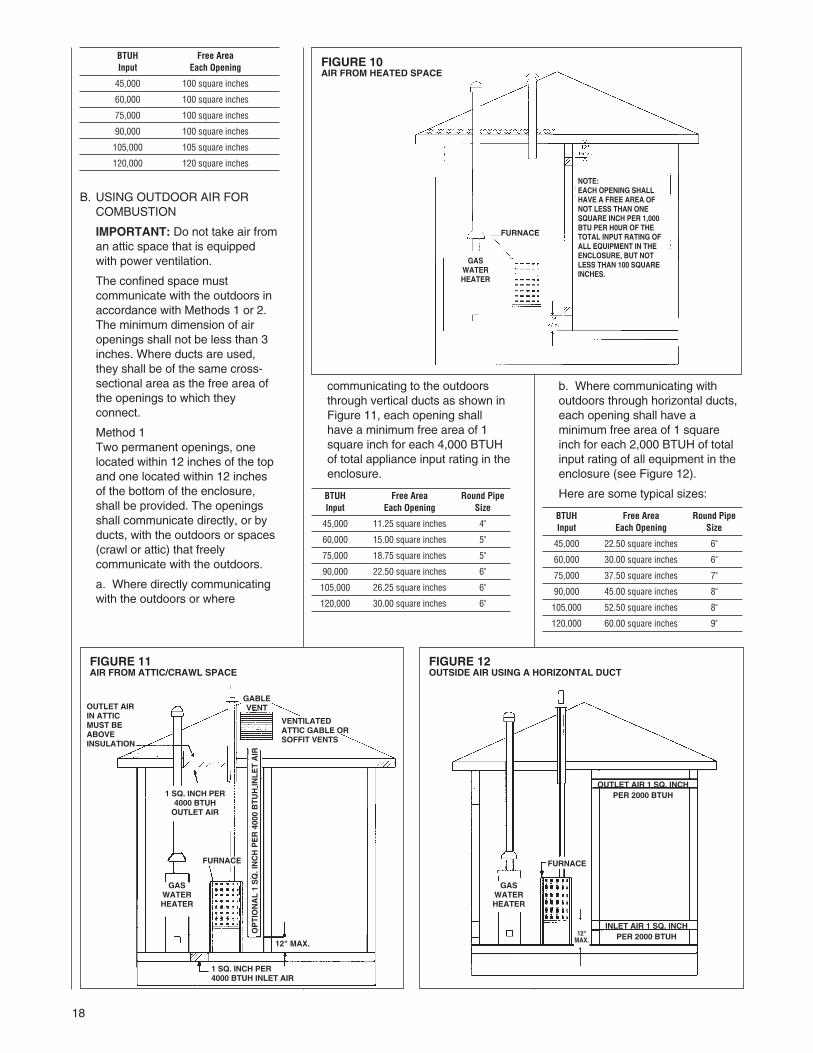
If combustion air is taken from theheated area, the openings musteach have at least 100 squareinches of free area. Each openingmust have at least one square inchof free area for each 1,000 BTUHof total input in the space. Hereare some examples of typicalopenings required.
COMBUSTION AND VENTILATION AIR
! WARNING
! WARNING
18
BTUH Free AreaInput Each Opening
45,000 100 square inches
60,000 100 square inches
75,000 100 square inches
90,000 100 square inches
105,000 105 square inches
120,000 120 square inches
B. USING OUTDOOR AIR FORCOMBUSTION
IMPORTANT: Do not take air froman attic space that is equippedwith power ventilation.
The confined space mustcommunicate with the outdoors inaccordance with Methods 1 or 2.The minimum dimension of airopenings shall not be less than 3inches. Where ducts are used,they shall be of the same cross-sectional area as the free area ofthe openings to which theyconnect.
Method 1Two permanent openings, onelocated within 12 inches of the topand one located within 12 inchesof the bottom of the enclosure,shall be provided. The openingsshall communicate directly, or byducts, with the outdoors or spaces(crawl or attic) that freelycommunicate with the outdoors.
a. Where directly communicatingwith the outdoors or where
communicating to the outdoorsthrough vertical ducts as shown inFigure 11, each opening shallhave a minimum free area of 1square inch for each 4,000 BTUHof total appliance input rating in theenclosure.
BTUH Free Area Round PipeInput Each Opening Size
45,000 11.25 square inches 4"
60,000 15.00 square inches 5"
75,000 18.75 square inches 5"
90,000 22.50 square inches 6"
105,000 26.25 square inches 6"
120,000 30.00 square inches 6"
b. Where communicating withoutdoors through horizontal ducts,each opening shall have aminimum free area of 1 squareinch for each 2,000 BTUH of totalinput rating of all equipment in theenclosure (see Figure 12).
Here are some typical sizes:
BTUH Free Area Round PipeInput Each Opening Size
45,000 22.50 square inches 6"
60,000 30.00 square inches 6"
75,000 37.50 square inches 7"
90,000 45.00 square inches 8"
105,000 52.50 square inches 8"
120,000 60.00 square inches 9"
FIGURE 11AIR FROM ATTIC/CRAWL SPACE
FIGURE 12OUTSIDE AIR USING A HORIZONTAL DUCT
FIGURE 10AIR FROM HEATED SPACE
NOTE:EACH OPENING SHALLHAVE A FREE AREA OFNOT LESS THAN ONESQUARE INCH PER 1,000BTU PER H0UR OF THETOTAL INPUT RATING OFALL EQUIPMENT IN THEENCLOSURE, BUT NOTLESS THAN 100 SQUAREINCHES.
GASWATERHEATER
FURNACE
GASWATERHEATER
GASWATERHEATER
FURNACE FURNACE
12" MAX.12"MAX.
1 SQ. INCH PER4000 BTUH INLET AIR
OUTLET AIR 1 SQ. INCHPER 2000 BTUH
INLET AIR 1 SQ. INCHPER 2000 BTUH
1 SQ. INCH PER4000 BTUHOUTLET AIR
OPTIONAL1SQ.INCHPER4000BTUHINLETAIR
VENTILATEDATTIC GABLE ORSOFFIT VENTS
GABLEVENTOUTLET AIR
IN ATTICMUST BEABOVEINSULATION

19
FIGURE 13COMBUSTION AIR FITTING
Method 2 (not shown)One permanent opening, locatedwithin 12 inches of the top of theenclosure, shall be permittedwhere the equipment hasclearances of at least 1 inch fromthe sides and back and 6 inchesfrom the front of the appliance.The opening shall directlycommunicate with the outdoors orcommunicate through a vertical orhorizontal duct to the outdoors orspaces (crawl or attic) that freelycommunicate with the outdoors,and shall have a minimum freearea of:
a. 1 square inch for each 3,000BTUH of the total input rating of allequipment located in the enclosureand
BTUH Free Area Round PipeInput Each Opening Size
45,000 15.00 square inches 4"
60,000 16.67 square inches 5"
75,000 25.00 square inches 6"
90,000 30.00 square inches 6"
105,000 35.00 square inches 7"
120,000 40.00 square inches 7"
b. Not less than the sum of theareas of all vent connectors in theconfined space.
If unit is installed where there is anexhaust fan, sufficient ventilationmust be provided to prevent theexhaust fan from creating a negativepressure.
Combustion air openings must not berestricted in any manner.
CONSULT LOCAL CODES FORSPECIAL REQUIREMENTS.
CONNECTION TOFURNACEIMPORTANT:When indoorcombustion air is used, the inlet airopening at the furnace must beprotected from accidental blockage.(See Figure 13).
UPFLOW
DOWNFLOW/HORIZONTAL
2" PVCDOUBLEELBOW
TOPOPTION
EXHAUST
2" PVC ELBOW
SIDEOPTION
2" PVCDOUBLEELBOW*
COMBUSTION AIREXHAUST
ATTACH DOUBLE ELBOW TO INTAKE AIRCOLLAR AND SECURE WITH TWO SHEETMETAL SCREWS TO PREVENT ACCIDENTALBLOCKAGE OF INTAKE AIR OPENING.
*NOTE: WHEN FURNACE IS INSTALLED IN A HORIZONTAL POSITIONONLY ONE 90° ELBOW IS REQUIRED. INSTALL THE ELBOW SO THEOPEN END IS POINTED DOWNWARD.
ATTACH DOUBLE ELBOW TO TOP INLETAIR OPENING OR 90° ELBOW TO SIDEINLET AIR OPENING TO PREVENTACCIDENTAL BLOCKAGE OF INTAKEOPENING. PLUG OPENING NOT USED.
I337I336
PREDRILL FOR SCREWS.
20
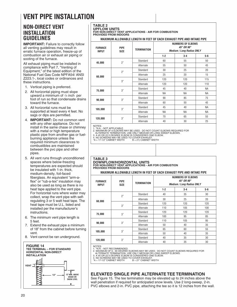
ELEVATED SINGLE PIPE ALTERNATETEETERMINATIONSee Figure 15. The tee termination may be elevated up to 24 inches above thewall penetration if required for anticipated snow levels. Use 2 long-sweep, 2-in.PVC elbows and 2-in. PVC pipe, attaching the tee so it is 12 inches from the wall.
NON-DIRECT VENTINSTALLATIONGUIDELINESIMPORTANT: Failure to correctly followall venting guidelines may result inerratic furnace operation, freeze-up ofcombustion air or exhaust air piping orsooting of the furnace.All exhaust piping must be installed incompliance with Part 7, “Venting ofEquipment,” of the latest edition of theNational Fuel Gas Code NPFA54/ ANSIZ223.1-, local codes or ordinances andthese instructions.1. Vertical piping is preferred.2. All horizontal piping must slope
upward a minimum of 1/4 inch perfoot of run so that condensate drainstoward the furnace.
3. All horizontal runs must besupported at least every 4 feet. Nosags or dips are permitted.
4. IMPORTANT: Do not common ventwith any other appliance. Do notinstall in the same chase or chimneywith a metal or high temperatureplastic pipe from another gas or fuel-burning appliance unless therequired minimum clearances tocombustibles are maintainedbetween the pvc pipe and otherpipes.
5. All vent runs through unconditionedspaces where below-freezingtemperatures are expected shouldbe insulated with 1-in. thick,medium-density, foil-facedfiberglass. An equivalent “arm-a-flex” or “rub-a-tex” insulation mayalso be used as long as there is noheat tape applied to the vent pipe.For horizontal runs where water maycollect, wrap the vent pipe with self-regulating 3 or 5 watt heat tape. Theheat tape must be U.L. listed andinstalled per the manufacturer’sinstructions.
6. The minimum vent pipe length is5 feet.
7. Extend the exhaust pipe a minimumof 18” from the cabinet before turningvent.
8. Vent cannot be ran underground.
FIGURE 14TEE TERMINAL – FOR STANDARDHORIZONTAL NON-DIRECTINSTALLATION
VENT
12" 12" MIN. ABOVEGRADE OR
SNOW LEVEL
NUMBERS OF ELBOWS45° OR 90°
Medium / Long Radius ONLY
1-2 3-4 5-6
2”Standard 60 55 50
45,000Alternate 55 50 45
2”Standard 30 25 20
Alternate 25 20 1560,000
3”Standard 120 120 115
Alternate 120 120 110
3”Standard 45 40 NA
75,000Alternate NA NA NA
3”Standard 90 85 75
90,000Alternate 60 50 45
105,000 3”Standard 45 40 NA
Alternate NA NA NA
120,000 3”Standard 70 65 55
Alternate 40 30 25
NOTES:1. *N.A. - NOT APPLICABLE.2. MAXIMUM OF 6 ELBOWS MAY BE USED. DO NOT COUNT ELBOWS REQUIRED FORALTERNATE TERMINATION. USE ONLY MEDIUM OR LONG SWEEP ELBOWS.
3. A 45 OR 22.5 DEGREE ELBOW IS CONSIDERED ONE ELBOW.4. NO SCREENS MAY BE USED TO COVER EXHAUST.*A = 17-1/2” CABINET WIDTH B = 21) CABINET WIDTH
FURNACEINPUT
VENT PIPE INSTALLATION
PIPESIZE
TERMINATION
TABLE 2UPFLOW UNITSFOR NON-DIRECT VENT APPLICATIONS - AIR FOR COMBUSTIONPROVIDED FROM INDOORS
MAXIMUM ALLOWABLE LENGTH IN FEET OF EACH EXHAUST PIPE AND INTAKE PIPE
NUMBERS OF ELBOWS45° OR 90°
Medium / Long Radius ONLY
1-2 3-4 5-6
2”Standard 40 35 30
Alternate 30 25 2060,000
3”Standard 120 120 120
Alternate 110 105 100
3”Standard 120 120 120
75,000Alternate 100 95 85
90,000 3”Standard 110 105 95
Alternate 50 40 35
105,000 3”Standard 65 60 55
Alternate 50 40 35
120,000 3”Standard 40 35 30
Alternate 40 35 30
NOTES:1. *N.R. - NOT RECOMMENDED.2. MAXIMUM OF 6 - 90 DEGREE ELBOWS MAY BE USED. DO NOT COUNT ELBOWS REQUIRED FORALTERNATE TERMINATION. USE ONLY MEDIUM OR LONG SWEEP ELBOWS.
3. A 45 OR 22.5 DEGREE ELBOW IS CONSIDERED ONE ELBOW.4. NO SCREENS MAY BE USED TO COVER EXHAUST.*A = 17-1/2” CABINET WIDTH B = 21” CABINET WIDTH
FURNACEINPUT
PIPESIZE
TERMINATION
TABLE 3DOWNFLOW/HORIZONTAL UNITSFOR NON-DIRECT VENT APPLICATIONS - AIR FOR COMBUSTIONPROVIDED FROM INDOORS
MAXIMUM ALLOWABLE LENGTH IN FEET OF EACH EXHAUST PIPE AND INTAKE PIPE
21
STANDARD INSTALLATIONSThe single-pipe system requires anexhaust pipe only. Combustion air maybe taken from the furnace installationarea or ducted to the furnace area fromthe outside.
Size the exhaust pipe as specified inTable 2. This table lists the maximumallowable length in feet of the exhaustpipe that may be used for all furnaceinputs as related to the number ofelbows required and the termination.(See shaded area.)
Vertical through-the-roof installations donot require a vent termination. Use 2-in.PVC pipe extending a minimum of 12inches above the anticipated level ofsnow accumulation. See exhaust piperequirements, Figure 19. When 3-in.vent pipe is used from furnace to theroof, reduce it to 2 inches beforepenetrating the roof. A maximum of 18inches of 2-in. pipe may be used belowthe roof. Maximum exposed vent lengthabove the roof line is 30”. Total 2” ventlength is a maximum of 48”.
Horizontal vent terminations require a2-in. PVC tee positioned 12 inches fromthe outside wall. See exhaust piperequirements, Figure 29. When 3-in.pipe is used from the furnace to theoutside wall, reduce it to 2 inchesbefore penetrating the wall. A maximumof 18 inches of 2-in. pipe may be usedinside the wall.
An alternate termination may be usedas shown in Figure 15 to clearanticipated snow levels. The tee maybe raised up to 24 inches above thewall penetration. Use two long-sweepradius bend, 2-in. PVC elbows and alength of 2-in. PVC pipe so that theelbows are on 24-in. centers.
NOTE: Extend the exhaust a minimumof 18" from the furnace top plate beforeturning vent.
NON-DIRECT VENT TERMINATIONLOCATION REQUIREMENTS
MOISTURE IN THE COMBUSTIONPRODUCTS CONDENSES AS ITLEAVES THE TERMINATION. THISCONDENSATE CAN FREEZE ONEXTERIOR WALLS, UNDER THEEAVES, AND ON SURROUNDINGOBJECTS. SOME DISCOLORATIONIS TO BE EXPECTED. HOWEVER,IMPROPER LOCATION ORINSTALLATION CAN CAUSESTRUCTURAL OR EXTERIOR FINISHDAMAGE TO THE BUILDING.
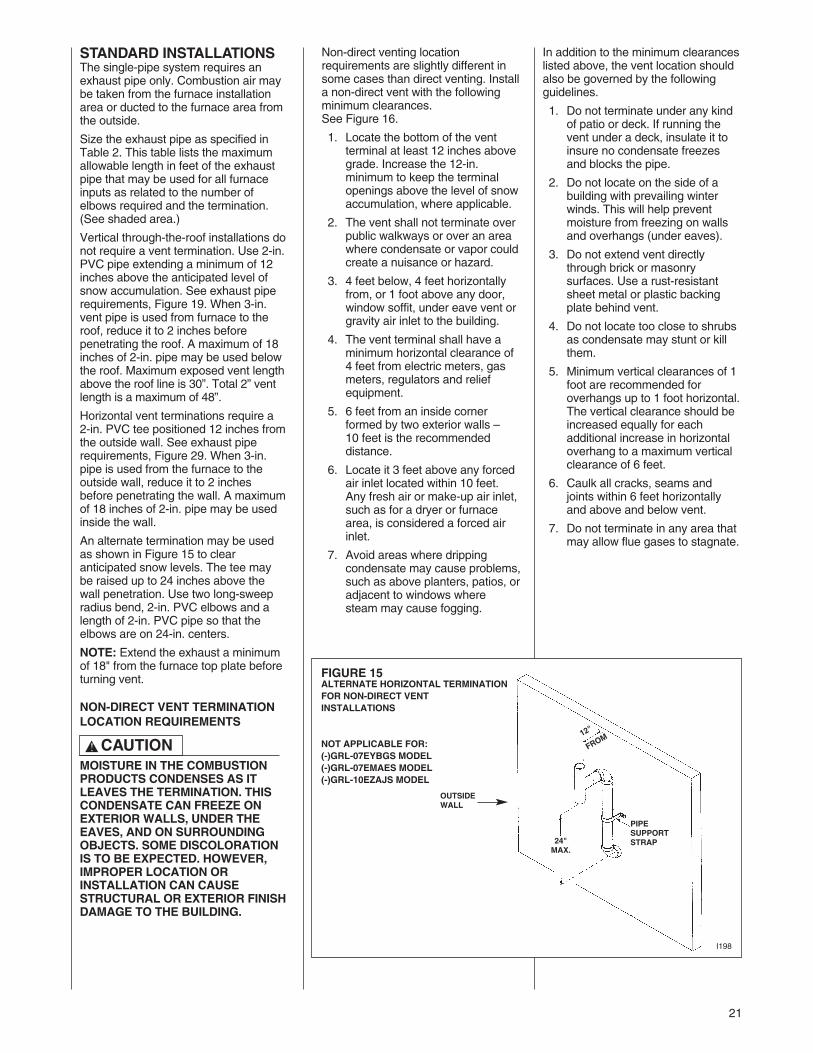
Non-direct venting locationrequirements are slightly different insome cases than direct venting. Installa non-direct vent with the followingminimum clearances.See Figure 16.
1. Locate the bottom of the ventterminal at least 12 inches abovegrade. Increase the 12-in.minimum to keep the terminalopenings above the level of snowaccumulation, where applicable.
2. The vent shall not terminate overpublic walkways or over an areawhere condensate or vapor couldcreate a nuisance or hazard.
3. 4 feet below, 4 feet horizontallyfrom, or 1 foot above any door,window soffit, under eave vent orgravity air inlet to the building.
4. The vent terminal shall have aminimum horizontal clearance of4 feet from electric meters, gasmeters, regulators and reliefequipment.
5. 6 feet from an inside cornerformed by two exterior walls –10 feet is the recommendeddistance.
6. Locate it 3 feet above any forcedair inlet located within 10 feet.Any fresh air or make-up air inlet,such as for a dryer or furnacearea, is considered a forced airinlet.
7. Avoid areas where drippingcondensate may cause problems,such as above planters, patios, oradjacent to windows wheresteam may cause fogging.
! CAUTION
In addition to the minimum clearanceslisted above, the vent location shouldalso be governed by the followingguidelines.
1. Do not terminate under any kindof patio or deck. If running thevent under a deck, insulate it toinsure no condensate freezesand blocks the pipe.
2. Do not locate on the side of abuilding with prevailing winterwinds. This will help preventmoisture from freezing on wallsand overhangs (under eaves).
3. Do not extend vent directlythrough brick or masonrysurfaces. Use a rust-resistantsheet metal or plastic backingplate behind vent.
4. Do not locate too close to shrubsas condensate may stunt or killthem.
5. Minimum vertical clearances of 1foot are recommended foroverhangs up to 1 foot horizontal.The vertical clearance should beincreased equally for eachadditional increase in horizontaloverhang to a maximum verticalclearance of 6 feet.
6. Caulk all cracks, seams andjoints within 6 feet horizontallyand above and below vent.
7. Do not terminate in any area thatmay allow flue gases to stagnate.
FIGURE 15ALTERNATE HORIZONTAL TERMINATIONFOR NON-DIRECT VENTINSTALLATIONS
NOT APPLICABLE FOR:(-)GRL-07EYBGS MODEL(-)GRL-07EMAES MODEL(-)GRL-10EZAJS MODEL
12"
FROM
24"MAX.
PIPESUPPORTSTRAP
OUTSIDEWALL
I198
22
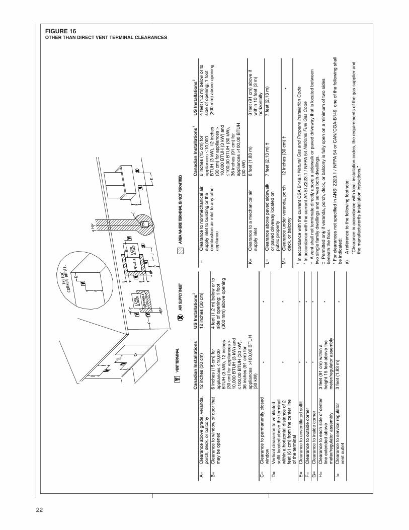
FIGURE 16OTHER THAN DIRECT VENT TERMINAL CLEARANCES
Nat
ural
Gas
and
Pro
pan
eIn
stal
latio
nC
od
eN
atio
nalF
uelG
asC
od
e
Can
adia
nIn
stal
lati
on
sU
SIn
stal
lati
on
sC
anad
ian
Inst
alla
tio
ns
US
Inst
alla
tio
ns
23
DIRECT VENTINSTALLATIONS
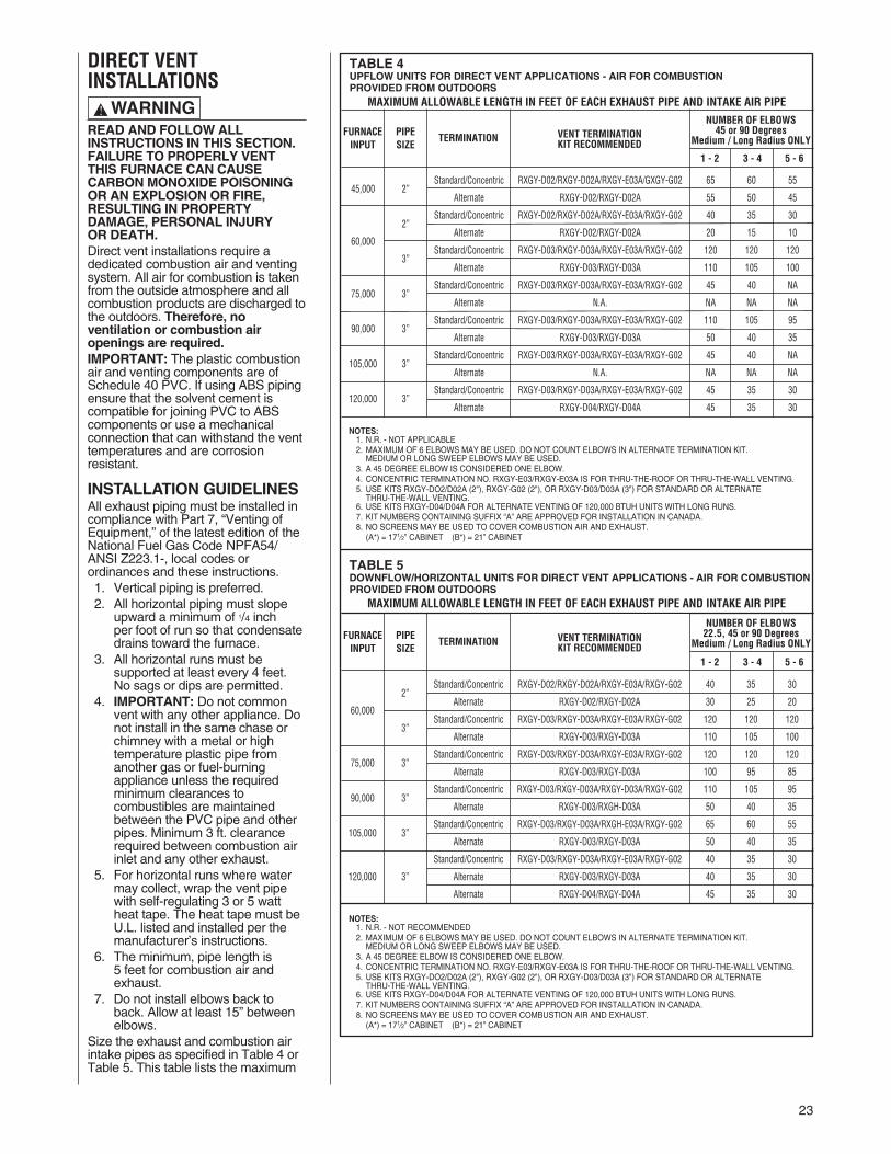
READ AND FOLLOW ALLINSTRUCTIONS IN THIS SECTION.FAILURE TO PROPERLY VENTTHIS FURNACE CAN CAUSECARBON MONOXIDE POISONINGOR AN EXPLOSION OR FIRE,RESULTING IN PROPERTYDAMAGE, PERSONAL INJURYOR DEATH.Direct vent installations require adedicated combustion air and ventingsystem. All air for combustion is takenfrom the outside atmosphere and allcombustion products are discharged tothe outdoors. Therefore, noventilation or combustion airopenings are required.IMPORTANT: The plastic combustionair and venting components are ofSchedule 40 PVC. If using ABS pipingensure that the solvent cement iscompatible for joining PVC to ABScomponents or use a mechanicalconnection that can withstand the venttemperatures and are corrosionresistant.
INSTALLATION GUIDELINESAll exhaust piping must be installed incompliance with Part 7, “Venting ofEquipment,” of the latest edition of theNational Fuel Gas Code NPFA54/ANSI Z223.1-, local codes orordinances and these instructions.1. Vertical piping is preferred.2. All horizontal piping must slope
upward a minimum of 1/4 inchper foot of run so that condensatedrains toward the furnace.
3. All horizontal runs must besupported at least every 4 feet.No sags or dips are permitted.
4. IMPORTANT: Do not commonvent with any other appliance. Donot install in the same chase orchimney with a metal or hightemperature plastic pipe fromanother gas or fuel-burningappliance unless the requiredminimum clearances tocombustibles are maintainedbetween the PVC pipe and otherpipes. Minimum 3 ft. clearancerequired between combustion airinlet and any other exhaust.
5. For horizontal runs where watermay collect, wrap the vent pipewith self-regulating 3 or 5 wattheat tape. The heat tape must beU.L. listed and installed per themanufacturer’s instructions.
6. The minimum, pipe length is5 feet for combustion air andexhaust.
7. Do not install elbows back toback. Allow at least 15” betweenelbows.
Size the exhaust and combustion airintake pipes as specified in Table 4 orTable 5. This table lists the maximum
! WARNING
Standard/Concentric RXGY-D02/RXGY-D02A/RXGY-E03A/GXGY-G02 65 60 5545,000 2”
Alternate RXGY-D02/RXGY-D02A 55 50 45
Standard/Concentric RXGY-D02/RXGY-D02A/RXGY-E03A/RXGY-G02 40 35 302”
Alternate RXGY-D02/RXGY-D02A 20 15 1060,000
3”Standard/Concentric RXGY-D03/RXGY-D03A/RXGY-E03A/RXGY-G02 120 120 120
Alternate RXGY-D03/RXGY-D03A 110 105 100
Standard/Concentric RXGY-D03/RXGY-D03A/RXGY-E03A/RXGY-G02 45 40 NA75,000 3”
Alternate N.A. NA NA NA
Standard/Concentric RXGY-D03/RXGY-D03A/RXGY-E03A/RXGY-G02 110 105 9590,000 3”
Alternate RXGY-D03/RXGY-D03A 50 40 35
Standard/Concentric RXGY-D03/RXGY-D03A/RXGY-E03A/RXGY-G02 45 40 NA105,000 3”
Alternate N.A. NA NA NA
Standard/Concentric RXGY-D03/RXGY-D03A/RXGY-E03A/RXGY-G02 45 35 30120,000 3”
Alternate RXGY-D04/RXGY-D04A 45 35 30
FURNACEINPUT
PIPESIZE
TERMINATION VENT TERMINATIONKIT RECOMMENDED
1 - 2 3 - 4 5 - 6
NUMBER OF ELBOWS45 or 90 Degrees
Medium / Long Radius ONLY
TABLE 4UPFLOW UNITS FOR DIRECT VENT APPLICATIONS - AIR FOR COMBUSTIONPROVIDED FROM OUTDOORS
MAXIMUM ALLOWABLE LENGTH IN FEET OF EACH EXHAUST PIPE AND INTAKE AIR PIPE
TABLE 5DOWNFLOW/HORIZONTAL UNITS FOR DIRECT VENT APPLICATIONS - AIR FOR COMBUSTIONPROVIDED FROM OUTDOORS
MAXIMUM ALLOWABLE LENGTH IN FEET OF EACH EXHAUST PIPE AND INTAKE AIR PIPE
FURNACEINPUT
PIPESIZE
TERMINATION VENT TERMINATIONKIT RECOMMENDED
1 - 2 3 - 4 5 - 6
NUMBER OF ELBOWS22.5, 45 or 90 Degrees
Medium / Long Radius ONLY
NOTES:1. N.R. - NOT RECOMMENDED2. MAXIMUM OF 6 ELBOWS MAY BE USED. DO NOT COUNT ELBOWS IN ALTERNATE TERMINATION KIT.MEDIUM OR LONG SWEEP ELBOWS MAY BE USED.
3. A 45 DEGREE ELBOW IS CONSIDERED ONE ELBOW.4. CONCENTRIC TERMINATION NO. RXGY-E03/RXGY-E03A IS FOR THRU-THE-ROOF OR THRU-THE-WALL VENTING.5. USE KITS RXGY-DO2/D02A (2"), RXGY-G02 (2"), OR RXGY-D03/D03A (3") FOR STANDARD OR ALTERNATETHRU-THE-WALL VENTING.
6. USE KITS RXGY-D04/D04A FOR ALTERNATE VENTING OF 120,000 BTUH UNITS WITH LONG RUNS.7. KIT NUMBERS CONTAINING SUFFIX “A” ARE APPROVED FOR INSTALLATION IN CANADA.8. NO SCREENS MAY BE USED TO COVER COMBUSTION AIR AND EXHAUST.(A*) = 171⁄2” CABINET (B*) = 21” CABINET
2”Standard/Concentric RXGY-D02/RXGY-D02A/RXGY-E03A/RXGY-G02 40 35 30
Alternate RXGY-D02/RXGY-D02A 30 25 2060,000
3”Standard/Concentric RXGY-D03/RXGY-D03A/RXGY-E03A/RXGY-G02 120 120 120
Alternate RXGY-D03/RXGY-D03A 110 105 100
Standard/Concentric RXGY-D03/RXGY-D03A/RXGY-E03A/RXGY-G02 120 120 12075,000 3”
Alternate RXGY-D03/RXGY-D03A 100 95 85
Standard/Concentric RXGY-D03/RXGY-D03A/RXGY-D03A/RXGY-G02 110 105 9590,000 3”
Alternate RXGY-D03/RXGH-D03A 50 40 35
Standard/Concentric RXGY-D03/RXGY-D03A/RXGH-E03A/RXGY-G02 65 60 55105,000 3”
Alternate RXGY-D03/RXGY-D03A 50 40 35
Standard/Concentric RXGY-D03/RXGY-D03A/RXGY-E03A/RXGY-G02 40 35 30
120,000 3” Alternate RXGY-D03/RXGY-D03A 40 35 30
Alternate RXGY-D04/RXGY-D04A 45 35 30
NOTES:1. N.R. - NOT APPLICABLE2. MAXIMUM OF 6 ELBOWS MAY BE USED. DO NOT COUNT ELBOWS IN ALTERNATE TERMINATION KIT.MEDIUM OR LONG SWEEP ELBOWS MAY BE USED.
3. A 45 DEGREE ELBOW IS CONSIDERED ONE ELBOW.4. CONCENTRIC TERMINATION NO. RXGY-E03/RXGY-E03A IS FOR THRU-THE-ROOF OR THRU-THE-WALL VENTING.5. USE KITS RXGY-DO2/D02A (2"), RXGY-G02 (2"), OR RXGY-D03/D03A (3") FOR STANDARD OR ALTERNATETHRU-THE-WALL VENTING.
6. USE KITS RXGY-D04/D04A FOR ALTERNATE VENTING OF 120,000 BTUH UNITS WITH LONG RUNS.7. KIT NUMBERS CONTAINING SUFFIX “A” ARE APPROVED FOR INSTALLATION IN CANADA.8. NO SCREENS MAY BE USED TO COVER COMBUSTION AIR AND EXHAUST.(A*) = 171⁄2” CABINET (B*) = 21” CABINET

24
COMBUSTION AIR FORDIRECTVENTINSTALLATIONSTHE COMBUSTION AIR SYSTEMDESIGNED FOR THIS FURNACEMUST BE USED.
When this furnace is installed as adirect vent forced air furnace, allcombustion air is supplied directly tothe burner through a special air inletsystem outlined in these instructions.This system consists of field-suppliedSchedule 40 or 26 SDR-PVC pipeand one of the following horizontalvent termination kits: (-)XGY-D02/D02A, (-)XGY-D03/D03A,(-)XGY-D04/D04A, or (-)XGY-E03A.
NOTE: Schedule 40 ABS-DWV pipeand fittings may be used as analternate to PVC pipe for thecombustion air inlet and vent pipes.
The combustion air for this furnace issupplied directly from the outdoorsthrough the combustion air inletsystem.
When the furnace is installed in thesame space with other gasappliances, such as a water heater,be sure there is an adequate supplyof combustion and ventilation air forthe other appliances. Do not delete orreduce the combustion air supplyrequired by the other gas appliancesin this space. See Z223.1, NationalFuel Gas Code (NFPA54) for deter-mining the combustion airrequirements for gas appliances. Anunconfined space must have at least50 cubic feet (volume) for each1,000 BTUH of the total input of allappliances in the space. If the openspace containing the appliances is ina building with tight construction(contemporary construction), outsideair may still be required for theappliances to burn and vent properly.Outside air openings should be sizedthe same as for a confined space.
STANDARDTERMINATIONSSTANDARD VERTICALTERMINATIONS
COMBUSTION AIR PIPING
Use two medium-radius sweepelbows to keep the inlet downward to
prevent entry of rain. See Figure 19for the proper relationship ofcombustion air to exhausttermination.
STANDARD HORIZONTALTERMINATIONS
COMBUSTION AIR PIPING
When 3-in. pipe is used between thefurnace and outside wall, reduce itto 2 inches before penetrating thewall. Up to 18 inches of 2-in. pipemay be used inside the wall.
The standard horizontal intake airtermination for all models is a 2-in.PVC coupling with a wind deflectorvane (provided) attached. Cut a21/4-in. length of 2-in. PVC pipe.Connect this pipe and another 2-in.PVC coupling to the coupling at thewall. The outer coupling mustterminate 4 inches from the wall.
IMPORTANT: To ensure properfurnace operation, the supplied vanemust be installed in the verticalposition with PVC solvent as shown inFigure 20, Detail B.
The combustion air inlet terminalmust be located with respect to theexhaust terminal as shown in Figure20, Detail C.
IMPORTANT: All furnaces withhorizontal air intakes, except thoseusing concentric vent kit (-)XGY-E03/E03A, must have a drain teeassembly and trap installed as closeto the furnace as possible. This is todrain any water that may be in thecombustion air pipe to prevent it fromentering the furnace combustionchamber.
These parts are included in kits(-)XGY-D02/D02A (for 2-in. pipe),(-)XGY-D03/D03A (for 3-in. pipe) and(-)XGY-D04/D04A (special for the120,000 BTU furnace installed withthe alternate horizontal termination).Attach the trap to the bottom of thetee with PVC solvent. Connect theother end to a suitable drain, as to thedownstream of a condensate trap onthe furnace.
STANDARD VERTICALTERMINATIONS
EXHAUST VENT PIPING
Vertical through-the-roof ventapplications do not require anexhaust terminal. The exhaust ventmust terminate at least 12 inchesabove the combustion intake air
termination. The exhaust vent formodels with inputs of 90,000 through120,000 BTUH is 2-in. PVC pipe120,000 BTUH models withexcessively long runs require 21/2”.Refer to Table 4 for properapplication. This mustbe reduced to 11/2“ the last12 inches for models with inputs of45,000 through 75,000 BTUH.See Figure 19.
STANDARD HORIZONTALTERMINATIONS
EXHAUST PIPING
For direct vent systems the standardtermination is 2-in. PVC pipeextending 12 inches from the wall forfurnaces with inputs from 105,000 to120,000 BTUH. Install a 2-in. couplingat the outside wall to prevent thetermination from being pushedinward. When 3-in. pipe is usedbetween the furnace and outside wall,reduce to 2 inches before penetratingthe wall. The standard termination is11/2 -in. PVC pipe extending outward12 inches from the wall for modelswith inputs of 45,000 to 75,000BTUH. Install a 2-in. to 11/2-in.coupling at the outside wall to preventpushing the termination back into thewall. See Figure 20, Detail A.
The combustion air and exhaustterminations must be at least 12inches above grade and must beoriented with respect to each other asshown in Figure 20, Detail B. Refer tosection on alternate venting optionswhen higher snow levels areanticipated.
ALTERNATETERMINATIONSALTERNATE HORIZONTALDIRECT VENT TERMINATIONS
(-)XGY-D02/D02A, -D03/D03A AND -D04/D04A
The combustion air and exhaustterminations may be raised amaximum of 24 inches above thewall penetration to maintain therequired 12 inch clearance abovegrade or snow level. See Figure 17.Size the pipe length according toTable 4 and Table 5.
Review the following guidelines:
• Size the entire vent systemaccording to the alternate, notstandard, termination shown inTable 4 and Table 5.
allowable length in feet of the exhaustand combustion air intake pipes thatmay be used for all furnace inputs asrelated to the number of elbowsrequired and the termination (seeshaded area).NOTE: Extend the exhaust a minimumof 18" from the furnace top platebefore turning vent.8. The maximum exposed vent
length (above the roof line) is 30”.
25
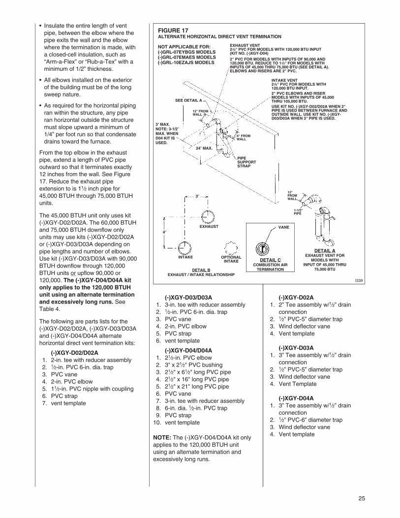
FIGURE 17ALTERNATE HORIZONTAL DIRECT VENT TERMINATION
SEE DETAIL A
24” MAX.
PIPESUPPORTSTRAP
3” MAX.NOTE: 3-1/2”MAX. WHEND04 KIT ISUSED.
EXHAUST VENT21/2" PVC FOR MODELS WITH 120,000 BTU INPUT(KIT NO. (-)XGY-D04)
2" PVC FOR MODELS WITH INPUTS OF 90,000 AND120,000 BTU. REDUCE TO 11/2" FOR MODELS WITHINPUTS OF 45,000 THRU 75,000 BTU (SEE DETAIL A).ELBOWS AND RISERS ARE 2" PVC.
INTAKE VENT21/2" PVC FOR MODELS WITH120,000 BTU INPUT.2" PVC ELBOWS AND RISERMODELS WITH INPUTS OF 45,000THRU 105,000 BTU.USE KIT NO. (-)XGY-D02/D02A WHEN 2"PIPE IS USED BETWEEN FURNACE ANDOUTSIDE WALL. USE KIT NO. (-)XGY-D03/D03A WHEN 3" PIPE IS USED.
I339
• Insulate the entire length of ventpipe, between the elbow where thepipe exits the wall and the elbowwhere the termination is made, witha closed-cell insulation, such as“Arm-a-Flex” or “Rub-a-Tex” with aminimum of 1/2” thickness.
• All elbows installed on the exteriorof the building must be of the longsweep nature.
• As required for the horizontal pipingran within the structure, any piperan horizontal outside the structuremust slope upward a minimum of1/4” per foot run so that condensatedrains toward the furnace.
From the top elbow in the exhaustpipe, extend a length of PVC pipeoutward so that it terminates exactly12 inches from the wall. See Figure17. Reduce the exhaust pipeextension to is 11⁄2 inch pipe for45,000 BTUH through 75,000 BTUHunits.
The 45,000 BTUH unit only uses kit(-)XGY-D02/D02A. The 60,000 BTUHand 75,000 BTUH downflow onlyunits may use kits (-)XGY-D02/D02Aor (-)XGY-D03/D03A depending onpipe lengths and number of elbows.Use kit (-)XGY-D03/D03A with 90,000BTUH downflow through 120,000BTUH units or upflow 90,000 or120,000. The (-)XGY-D04/D04A kitonly applies to the 120,000 BTUHunit using an alternate terminationand excessively long runs. SeeTable 4.
The following are parts lists for the(-)XGY-D02/D02A, (-)XGY-D03/D03Aand (-)XGY-D04/D04A alternatehorizontal direct vent termination kits:
(-)XGY-D02/D02A1. 2-in. tee with reducer assembly2. 1⁄2-in. PVC 6-in. dia. trap3. PVC vane4. 2-in. PVC elbow5. 11⁄2-in. PVC nipple with coupling6. PVC strap7. vent template
(-)XGY-D03/D03A1. 3-in. tee with reducer assembly2. 1⁄2-in. PVC 6-in. dia. trap3. PVC vane4. 2-in. PVC elbow5. PVC strap6. vent template
(-)XGY-D04/D04A1. 21⁄2-in. PVC elbow2. 3" x 21⁄2" PVC bushing3. 21⁄2" x 61⁄2" long PVC pipe4. 21⁄2" x 16" long PVC pipe5. 21⁄2" x 21" long PVC pipe6. PVC vane7. 3-in. tee with reducer assembly8. 6-in. dia. 1⁄2-in. PVC trap9. PVC strap10. vent template
NOTE: The (-)XGY-D04/D04A kit onlyapplies to the 120,000 BTUH unitusing an alternate termination andexcessively long runs.
3”
4”EXHAUST VANE
INTAKE OPTIONALINTAKE
DETAIL BEXHAUST / INTAKE RELATIONSHIP
DETAIL AEXHAUST VENT FOR
MODELS WITHINPUT OF 45,000 THRU
75,000 BTU
DETAIL CCOMBUSTION AIRTERMINATION
4" FROMWALL
12"FROMWALL
1-1/2"PIPE
12" FROMWALL
NOT APPLICABLE FOR:(-)GRL-07EYBGS MODELS(-)GRL-07EMAES MODELS(-)GRL-10EZAJS MODELS
(-)XGY-D02A1. 2” Tee assembly w/1⁄2” drain
connection2. 1⁄2” PVC-5” diameter trap3. Wind deflector vane4. Vent template
(-)XGY-D03A1. 3” Tee assembly w/1⁄2” drain
connection2. 1⁄2” PVC-5” diameter trap3. Wind deflector vane4. Vent Template
(-)XGY-D04A1. 3” Tee assembly w/1⁄2” drain
connection2. 1⁄2” PVC-6” diameter trap3. Wind deflector vane4. Vent template
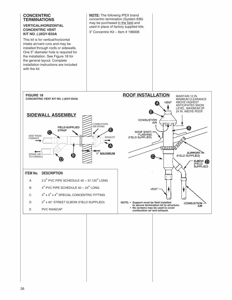
26
FIGURE 18CONCENTRIC VENT KIT NO. (-)XGY-E03A
SIDEWALL ASSEMBLY
ROOF INSTALLATION
1" MAXIMUM
FIELD-SUPPLIEDSTRAP
ITEM No. DESCRIPTION
A 2.5" PVC PIPE SCHEDULE 40 -- 37.125" LONG
B 4" PVC PIPE SCHEDULE 40 -- 24" LONG
C 3" x 3" x 4" SPECIAL CONCENTRIC FITTING
D 3" x 45° STREET ELBOW (FIELD SUPPLIED)
E PVC RAINCAP
E
B
A
C
D
E
B
A
C
D
CONCENTRICTERMINATIONSVERTICAL/HORIZONTALCONCENTRIC VENTKIT NO. (-)XGY-E03A
This kit is for vertical/horizontalintake air/vent runs and may beinstalled through roofs or sidewalls.One 5” diameter hole is required forthe installation. See Figure 18 forthe general layout. Completeinstallation instructions are includedwith the kit.
MAINTAIN 12 IN.MINIMUM CLEARANCEABOVE HIGHESTANTICIPATED SNOWLEVEL. MAXIMUM OF24 IN. ABOVE ROOF.
NOTE: • Support must be field installedto secure termination kit to structure.
• No screens may be used to covercombustion air and exhaust.
NOTE: The following IPEX brandconcentric termination (System 636)may be purchased in the field andused in place of factory supplied kits:
3” Concentric Kit – Item # 196006
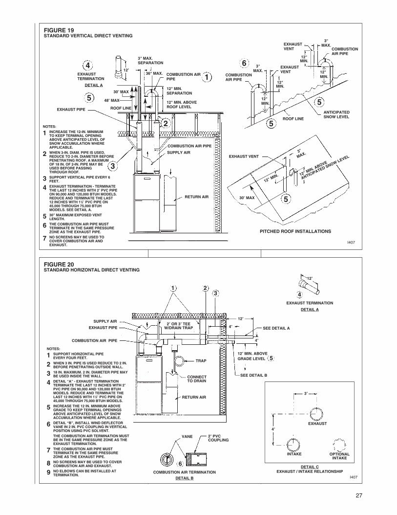
27
FIGURE 19STANDARD VERTICAL DIRECT VENTING
FIGURE 20STANDARD HORIZONTAL DIRECT VENTING
I407
3" MAX.SEPARATION
36" MAX. COMBUSTION AIRPIPE
12" MIN.SEPARATION
12" MIN. ABOVEROOF LEVELROOF LINEEXHAUST PIPE
COMBUSTION AIR PIPE
SUPPLY AIR
RETURN AIR
EXHAUST VENT
3"MAX.
EXHAUSTVENT
ROOF LINE
COMBUSTIONAIR PIPE
12"MIN.
12"MIN.
ANTICIPATEDSNOW LEVEL
COMBUSTIONAIR PIPE
3"MAX.EXHAUST
VENT
12"MIN.
12"MIN.
3"
MAX.
12"MIN
. 12"MIN
. ABOVE
ANTIC
IPATED
SNOW LEV
EL
NOTES:
1 INCREASE THE 12-IN. MINIMUMTO KEEP TERMINAL OPENINGABOVE ANTICIPATED LEVEL OFSNOW ACCUMULATION WHEREAPPLICABLE.
2 WHEN 3-IN. DIAM. PIPE IS USED,REDUCE TO 2-IN. DIAMETER BEFOREPENETRATING ROOF. A MAXIMUMOF 18 IN. OF 2-IN. PIPE MAY BEUSED BEFORE PASSINGTHROUGH ROOF.
3 SUPPORT VERTICAL PIPE EVERY 6FEET.
4 EXHAUST TERMINATION - TERMINATETHE LAST 12 INCHES WITH 2” PVC PIPEON 90,000 AND 120,000 BTUH MODELS.REDUCE AND TERMINATE THE LAST12 INCHES WITH 11/2” PVC PIPE ON45,000 THROUGH 75,000 BTUHMODELS. SEE DETAIL A.
5 30” MAXIMUM EXPOSED VENTLENGTH.
6 THE COMBUSTION AIR PIPE MUSTTERMINATE IN THE SAME PRESSUREZONE AS THE EXHAUST PIPE.
7 NO SCREENS MAY BE USED TOCOVER COMBUSTION AIR ANDEXHAUST.
PITCHED ROOF INSTALLATIONS
NOTES:
1 SUPPORT HORIZONTAL PIPEEVERY FOUR FEET.
2 WHEN 3 IN. PIPE IS USED REDUCE TO 2 IN.BEFORE PENETRATING OUTSIDE WALL.
3 18 IN. MAXIMUM. 2 IN. DIAMETER PIPE MAYBE USED INSIDE THE WALL.
4 DETAIL “A” - EXHAUST TERMINATIONTERMINATE THE LAST 12 INCHES WITH 2”PVC PIPE ON 90,000 AND 120,000 BTUHMODELS. REDUCE AND TERMINATE THELAST 12 INCHES WITH 11/2” PVC PIPE ON45,000 THROUGH 75,000 BTUH MODELS.
5 INCREASE THE 12 IN. MINIMUM ABOVEGRADE TO KEEP TERMINAL OPENINGSABOVE ANTICIPATED LEVEL OF SNOWACCUMULATION WHERE APPLICABLE.
6 DETAIL “B”, INSTALL WIND DEFLECTORVANE IN 2 IN. PVC COUPLING IN VERTICALPOSITION USING PVC SOLVENT.THE COMBUSTION AIR TERMINATION MUSTBE IN THE SAME PRESSURE ZONE AS THEEXHAUST TERMINATION.
7 THE COMBUSTION AIR PIPE MUSTTERMINATE IN THE SAME PRESSUREZONE AS THE EXHAUST PIPE.
8 NO SCREENS MAY BE USED TO COVERCOMBUSTION AIR AND EXHAUST.
9 NO ELBOWS CAN BE INSTALLED ATTERMINATION.
3”
12”
4”
4”
SEE DETAIL A
VANE 2” PVCCOUPLING
12” MIN. ABOVEGRADE LEVEL 5
SEE DETAIL B
2” OR 3” TEEW/DRAIN TRAP
RETURN AIR
TRAP
SUPPLY AIR
EXHAUST PIPE
COMBUSTION AIR PIPE
CONNECTTO DRAIN
12”
4”EXHAUST
INTAKE OPTIONALINTAKE
DETAIL CEXHAUST / INTAKE RELATIONSHIP
EXHAUST TERMINATION
DETAIL A
COMBUSTION AIR TERMINATION
DETAIL B
1 23
I407
3
5
5
5
4
6
1
6
2
48” MAX
30” MAX
4
530” MAX
EXHAUSTTERMINATION
DETAIL A
12”

28
LOCATION REQUIREMENTSHORIZONTAL DIRECT VENTS
THE COMBUSTION PRODUCTSAND MOISTURE IN THE FLUEGASES WILL CONDENSE AS THEYLEAVE THE TERMINATION. THECONDENSATE CAN FREEZE ONTHE EXTERIOR WALL, UNDERTHE EAVES AND ONSURROUNDING OBJECTS. SOMEDISCOLORATION TO THEEXTERIOR OF THE BUILDING ISTO BE EXPECTED. HOWEVER,IMPROPER LOCATION ORINSTALLATION CAN RESULT INSTRUCTURAL OR EXTERIORFINISH DAMAGE TO THEBUILDING AND MAYRECIRCULATE PRODUCTS OFCOMBUSTION INTO THECOMBUSTION AIR TERMINAL ANDFREEZE.
The vent must be installed with thefollowing minimum clearances. SeeFigures 21 and 22.
1. The bottom of the vent terminaland the air inlet shall be locatedat least 12 inches above grade.Increase the 12-in. minimum tokeep the terminal openingsabove the level of snowaccumulation, where applicable.
2. The vent shall not terminate overpublic walkways or over an areawhere condensate or vapor couldcreate a nuisance or hazard.
3. The vent terminal shall belocated at least one foot from anyopening through which fluegases could enter a building.
4. The vent terminal shall be atleast 3 feet above any forced airinlet located within 10 feet,except the combustion air inlet ofa direct vent appliance.
5. The vent terminal shall have aminimum horizontal clearance of4 feet from electric meters, gasmeters, regulators and reliefequipment.
6. Locate the furnace combustionair inlet minimum of 3 feet fromthe vent of any other gas or fuelburning appliance or clothesdryer to prevent recirculation ofthe flue gases into the furnacecombustion air inlet. The onlyexception to this requirement isthe case of multiventing two ormore furnaces, which is coveredin the section on multiventing inthese instructions.
In addition to the minimum clearanceslisted above, the vent locationshould also be governed by thefollowing guidelines.
1. Do not terminate under anykind of patio or deck. If runningthe vent under a deck, insulateit to insure no condensatefreezes and blocks the pipe.
2. Do not terminate behind any areathat may allow the flue productsto become stagnant andrecirculate.
3. Do not locate on the side of abuilding with prevailing winterwinds. This will help preventmoisture from freezing on wallsand overhangs (under eaves).
4. Do not extend vent directlythrough brick or masonrysurfaces. Use a rust-resistantsheet metal or plastic backingplate behind vent.
5. Do not locate too close to shrubsas condensate may stunt orkill them.
6. Minimum vertical clearances of 1foot are recommended foroverhangs up to 1 foot horizontal.The vertical clearance should beincreased equally for eachadditional increase in horizontaloverhang to a maximum verticalclearance of 6 feet.
7. Caulk all cracks, seams andjoints within 6 feet horizontallyand above and below vent.
8. Painted surfaces must be soundand in good condition with nocracking, peeling, etc. Paintedsurfaces will requiremaintenance.
9. Do not expose 3" x 2" reducer/bushing to outdoor ambienttemperatures.
FIGURE 21MOISTURE ZONES
! CAUTION
2 FT. SQ. SHEET METAL PLATE ON BRICK ORMASONRY SURFACE RECOMMENDED, BUTNOT REQUIRED BY CODE.

29
FIGURE 22DIRECT VENT TERMINAL CLEARANCES≤
Nat
ural
Gas
and
Pro
pan
eIn
stal
latio
nC
od
eN
atio
nalF
uelG
asC
od
e
Can
adia
nIn
stal
lati
on
sU
SIn
stal
lati
on
sC
anad
ian
Inst
alla
tio
ns
US
Inst
alla
tio
ns

30
FIGURE 24TWO FURNACE VENTING THROUGH WALL
FIGURE 23TWO FURNACE VENTING THROUGH ROOF
CONCENTRIC VENTING CONCENTRIC VENTING
MINIMUM 12” ABOVE AVERAGESNOW ACCUMULATION. MAXIMUM
OF 24 IN. ABOVE ROOF.
COMBUSTIONAIR INTAKE2” PVC
12” MIN.ABOVE
SNOW
LEVEL
6”MIN
.
10”RECOMMENDED
COMBUSTIONAIR INTAKE2” PVC COUPLINGWITH VALVE INVERTICAL POSITION
EXHAUST VENT
6” MINIMUM10” RECOMMENDED
MAXIMUM 1”DISTANCEFROM WALL
MINIMUM 12”ABOVE GRADE
SEE CONCENTRIC VENT INSTALLATIONINSTRUCTIONS.
SEE CONCENTRICVENT INSTALLATIONINSTRUCTIONS
TWO-PIPE VENTING TWO-PIPE VENTING
3" MIN.24" MAX.
8" MIN.24" MAX.
3" MIN.24" MAX.
8" MIN.24" MAX.
MULTIVENTINGIF VENTING TWO OR MOREFURNACES NEAR EACH OTHER ISREQUIRED, EACH FURNACEMUST BE INDIVIDUALLY VENTED– NO COMMON VENTING ISPERMITTED. See Figures 23 and 24for positioning of the terminations.When more than two furnaces are tobe vented, there must be at least 4feet between the first two furnacesand the third, etc.

31
NOTE: The vent illustration in Figure26 can be used for non-direct ventterminations also.
(-)XGY-G02 Side Wall VentThis termination for horizontal ventingonly.IMPORTANT: Do not install on theprevailing winter wind side of thestructure. Observe same clearancespecified for horizontal, standardtermination.NOTE: Multi-venting-No commonventing.
NOTE: Install the vent and air intakepiping into the vent plate openings.Seal all gaps between the pipes andwall. Be Sure To Use SiliconeSealant to seal the vent pipe to thevent cap to permit field disassemblyfor annual inspection and cleaning.Also seal all pipe penetrations in wall.To prevent possibility of condensatefreeze-up or recirculation, do notinstall vent kits one above theother.
FIGURE 25VENT KIT INSTALLATION OPTIONS
EXHAUST
AIR
INTAKE
FIGURE 26TYPICAL INSTALLATIONS

32
FIGURE 27UPFLOW COMBUSTION AIR AND VENT PIPE CONNECTION
I329
CONDENSATE TRAP
CONNECTOR
INDUCED DRAFTBLOWER
PLUG OPT. COMBUSTIONAIR POSITION
NOTE:WHEN COMBUSTION AIR IS INOPTIONAL POSITION SWAP LOCATIONOF 2" PVC MALE ADAPTER AND “O”RING WITH PLUG.
EXHAUST TRANSITION
EXHAUSTOUTLET AIR PIPE
EXHAUSTVENT CAP/PLUG
TOP PLATE
“O” RING COMBUSTIONAIR ADAPTER
DRAIN HOSES(AS SHIPPED FROM
FACTORY)
CONNECTING TO FURNACEIMPORTANT: Clean and debur allpipe cuts. The shavings must not beallowed to block the exhaust,combustion air or condensate drainpipes.
UPFLOW FURNACEThe exhaust pipe connection is a 2-in.female PVC pipe fitting extendingthrough the left side of the furnace topplate. This opening has a protectivecap which should be removed justprior to installing the exhaust pipe.When 2-in. pipe is used, connect itdirectly to this fitting. When 3-in. pipeis used, connect a 2 to 3-in. couplingto this fitting with a short piece of 2-in.PVC pipe.
The combustion air connectionis at the right side of the top plate.An alternate combustion airconnection may be made on the rightside of the jacket. This opening has aplastic cap. A combustion airconnection fitting is supplied with thefurnace and it must be installed in thefurnace by screwing it into theopening. Make sure the rubber“O-ring” supplied with the furnace isused with this fitting. See Figure 27.
DOWNFLOW/HORIZONTALFURNACEThe exhaust pipe connection is a 2-in.female PVC pipe fitting extendingthrough the right side of the furnacetop cover. This opening has a pro-tective cap which should be removedjust prior to installing the exhaustpipe. When 3-in. pipe is used,connect a 2 to 3-in. coupling to thisfitting with a short piece of 2-in. PVCpipe.
The combustion air connection is a 2-in. extruded hole on the left side ofthe top plate. When a 2-in. pipe isused, attach a 2-in. PVC couplingover this hole with RTV sealant, drilltwo pilot holes, and add two sheetmetal screws through the couplinginto the extrusion to secure it in placebefore piping. When 3-in. pipe isused, connect a 2 to 3-in. coupling tothis fitting with a short piece of 2-in.PVC pipe. See Figure 28.
FIGURE 28DOWNFLOW/HORIZONTAL COMBUSTION AIR AND VENT PIPE CONNECTION
EXHAUST VENTCAP/PLUG
EXHAUSTPIPE - PVC
EXHAUSTCONNECTOR
EXHAUSTTRANSITION
TOP PLATE
COUPLING
COMBUSTIONAIR CHASE
EXHAUSTOUTLET AIR PIPE
a103101
NOTE:ATTACH COUPLING TOEXTRUDED COLLARWITH TWO SCREWS. PUTBEAD OF SILICONEAROUND BASE BEFOREMOUNTING COUPLING.
INDUCED DRAFTBLOWER

33
CONDENSATE DRAIN/NEUTRALIZER
FIGURE 29UPFLOW CONDENSATE DRAIN
GENERAL INFORMATION
DO NOT RUN DRAIN OUTDOORS.FREEZING OF CONDENSATE CANCAUSE PROPERTY DAMAGE.IMPORTANT: Do not connect into acommon drain line with an air con-ditioner evaporator coil drain. A blockedor restricted drain line can result inover-flow of the coil pan and negate thefurnace blocked drain shutoff control.FILL TRAP ASSEMBLY WITHWATER BEFORE OPERATING THEFURNACE. This can be done byremoving the drain hosefrom the trap and pouring about acup of water into the vent trap. Waterwill flow into the house drain when thetrap is full.If local codes require, install acondensate neutralizer cartridge in thedrain line. Install cartridge in horizontalposition only. Also install an overflowline if routing to a floor drain. SeeFigure 29.If no floor drain is available, install acondensate pump that is resistant toacidic water. Pumps are available fromyour local distributor. If pump used isnot resistant to acidic water, acondensate neutralizer must be usedahead of the pump. The condensatepump must have an auxiliary safetyswitch to prevent operation of thefurnace and resulting overflow ofcondensate in the event of pumpfailure. The safety switch must be wiredthrough the “R” circuit only (low voltage)to provide operation in either heating orcooling modes.
UPFLOW MODELSThe condensate drain trap is located inthe blower compartment on the left-hand side of the jacket. A short piece of1/2-in. PVC pipe and a 1/2-in. tee areprovided. Connect the 1/2-in. pipe to theelbow on the trap and the tee to thispipe so that the open end is upward.Run a drain tube from the bottom of thetee to a floor drain or condensatepump.IMPORTANT: The upflow model onlyhas a new drain system. There is a thirdport on the drain trap (marked by a redcap) for the hose attached to theinduced draft motor. Remove plug ininducer drain hose and remove cap offdrain trap before connecting inducerdrain hose to drain trap. All three hosesMUST be attached during operation ofthe furnace. Be sure all three hoses aresecured to the drain trap using the hoseclamps provided in the parts bag.
IMPORTANT: If installing the unit overa finished ceiling or living area, becertain to install an auxiliary condensatedrain pan under the entire unitextending out under the condensatetee.IMPORTANT: There are two optionswhen choosing a height for thecondensate riser:CONDENSATE OVERFLOW: With a 5inch riser installed above the tee, ablocked drain will result in overflow fromthe riser.FURNACE SHUTDOWN: To cause thefurnace to shut down when a blockeddrain is present, install a riser which is aminimum of 1013/16“. If the furnace isinstalled in an attic, crawlspace or otherarea where freezing temperatures mayoccur, the furnace drain can freezewhile shut off for long periods of time.
Use a solvent cement that iscompatible with PVC material. Cut thedrain hoses to the appropriate lengthand connect to the trap with hoseclamps. Tighten the clamps withpliers and check for leaks afterattaching.
IMPORTANT: The inducer drain hosemust slant downward away frominducer. If the hose is not slanted,the inducer will fill with water andcause the pressure switch to open,causing nuisance failures orintermittent operation.
! CAUTION
I408
1013/16
CONDENSATE TRAP
TO FLOOR DRAIN OR CONDENSATE PUMP
OVERFLOW LINE(REQUIRED ONLY WHENOPTIONAL NEUTRALIZERCARTRIDGE IS USED.)
DRAIN LINENEUTRALIZER CARTRIDGE (OPTIONAL)
NOTE:SEE UPFLOW MODELNOTES FOR PIPEHEIGHT
NOTE: CONNECTINDUCER DRAIN HOSETO SMALLER PORT ONCONDENSATE TRAP.
NOTE: INDUCERDRAIN HOSEMUST SLANTDOWNWARDAWAY FROMINDUCER.
CONDENSATE TRAP
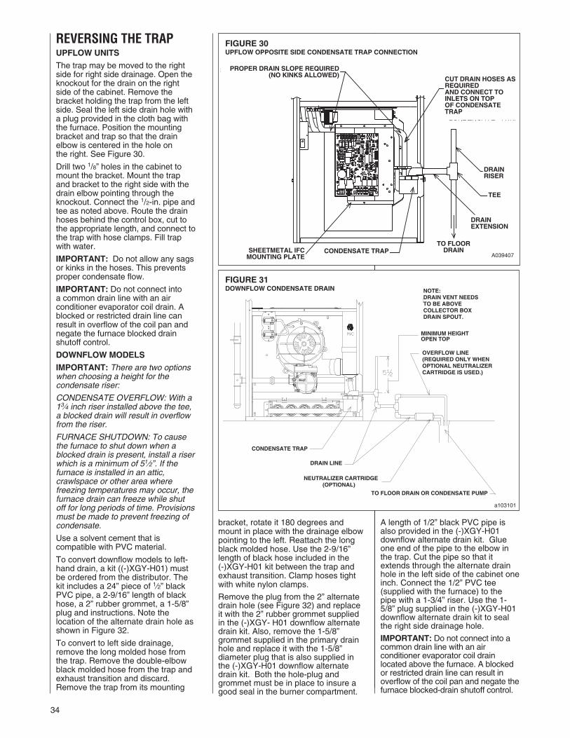
34
bracket, rotate it 180 degrees andmount in place with the drainage elbowpointing to the left. Reattach the longblack molded hose. Use the 2-9/16”length of black hose included in the(-)XGY-H01 kit between the trap andexhaust transition. Clamp hoses tightwith white nylon clamps.
Remove the plug from the 2” alternatedrain hole (see Figure 32) and replaceit with the 2” rubber grommet suppliedin the (-)XGY- H01 downflow alternatedrain kit. Also, remove the 1-5/8”grommet supplied in the primary drainhole and replace it with the 1-5/8”diameter plug that is also supplied inthe (-)XGY-H01 downflow alternatedrain kit. Both the hole-plug andgrommet must be in place to insure agood seal in the burner compartment.
FIGURE 30UPFLOW OPPOSITE SIDE CONDENSATE TRAP CONNECTION
REVERSING THE TRAPUPFLOW UNITS
The trap may be moved to the rightside for right side drainage. Open theknockout for the drain on the rightside of the cabinet. Remove thebracket holding the trap from the leftside. Seal the left side drain hole witha plug provided in the cloth bag withthe furnace. Position the mountingbracket and trap so that the drainelbow is centered in the hole onthe right. See Figure 30.
Drill two 1/8” holes in the cabinet tomount the bracket. Mount the trapand bracket to the right side with thedrain elbow pointing through theknockout. Connect the 1/2-in. pipe andtee as noted above. Route the drainhoses behind the control box, cut tothe appropriate length, and connect tothe trap with hose clamps. Fill trapwith water.
IMPORTANT: Do not allow any sagsor kinks in the hoses. This preventsproper condensate flow.
IMPORTANT: Do not connect intoa common drain line with an airconditioner evaporator coil drain. Ablocked or restricted drain line canresult in overflow of the coil pan andnegate the furnace blocked drainshutoff control.
DOWNFLOW MODELS
IMPORTANT: There are two optionswhen choosing a height for thecondensate riser:
CONDENSATE OVERFLOW: With a13⁄4 inch riser installed above the tee,a blocked drain will result in overflowfrom the riser.
FURNACE SHUTDOWN: To causethe furnace to shut down when ablocked drain is present, install a riserwhich is a minimum of 51⁄2”. If thefurnace is installed in an attic,crawlspace or other area wherefreezing temperatures may occur, thefurnace drain can freeze while shutoff for long periods of time. Provisionsmust be made to prevent freezing ofcondensate.
Use a solvent cement that iscompatible with PVC material.
To convert downflow models to left-hand drain, a kit ((-)XGY-H01) mustbe ordered from the distributor. Thekit includes a 24” piece of 1⁄2” blackPVC pipe, a 2-9/16” length of blackhose, a 2” rubber grommet, a 1-5/8”plug and instructions. Note thelocation of the alternate drain hole asshown in Figure 32.
To convert to left side drainage,remove the long molded hose fromthe trap. Remove the double-elbowblack molded hose from the trap andexhaust transition and discard.Remove the trap from its mounting
CUT DRAIN HOSES ASREQUIREDAND CONNECT TOINLETS ON TOPOF CONDENSATETRAP
DRAINRISER
TEE
DRAINEXTENSION
PROPER DRAIN SLOPE REQUIRED(NO KINKS ALLOWED)
CONDENSATE TRAPSHEETMETAL IFCMOUNTING PLATE
TO FLOORDRAIN
A039407
FIGURE 31DOWNFLOW CONDENSATE DRAIN
CONDENSATE TRAP
DRAIN LINE
NOTE:DRAIN VENT NEEDSTO BE ABOVECOLLECTOR BOXDRAIN SPOUT.
A length of 1/2” black PVC pipe isalso provided in the (-)XGY-H01downflow alternate drain kit. Glueone end of the pipe to the elbow inthe trap. Cut the pipe so that itextends through the alternate drainhole in the left side of the cabinet oneinch. Connect the 1/2” PVC tee(supplied with the furnace) to thepipe with a 1-3/4” riser. Use the 1-5/8” plug supplied in the (-)XGY-H01downflow alternate drain kit to sealthe right side drainage hole.
IMPORTANT: Do not connect into acommon drain line with an airconditioner evaporator coil drainlocated above the furnace. A blockedor restricted drain line can result inoverflow of the coil pan and negate thefurnace blocked-drain shutoff control.
NEUTRALIZER CARTRIDGE(OPTIONAL)
OVERFLOW LINE(REQUIRED ONLY WHENOPTIONAL NEUTRALIZERCARTRIDGE IS USED.)
MINIMUM HEIGHTOPEN TOP
TO FLOOR DRAIN OR CONDENSATE PUMP
a103101
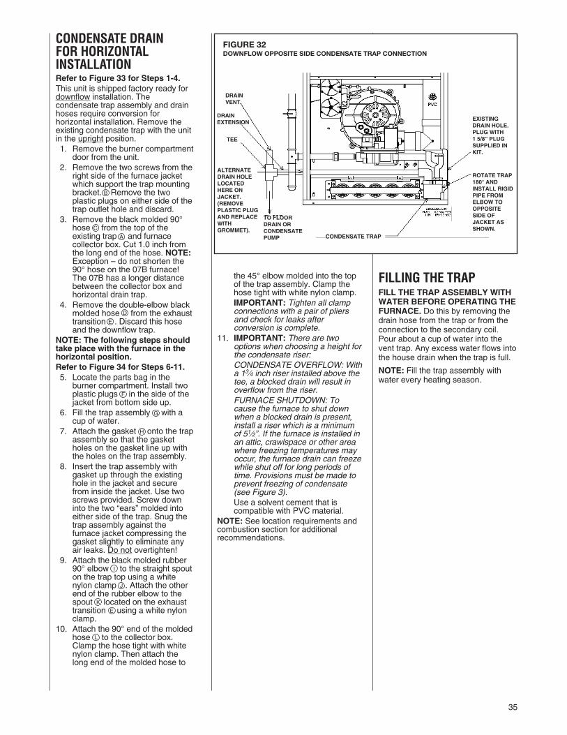
35
CONDENSATE DRAINFOR HORIZONTALINSTALLATIONRefer to Figure 33 for Steps 1-4.This unit is shipped factory ready fordownflow installation. Thecondensate trap assembly and drainhoses require conversion forhorizontal installation. Remove theexisting condensate trap with the unitin the upright position.1. Remove the burner compartment
door from the unit.2. Remove the two screws from the
right side of the furnace jacketwhich support the trap mountingbracket. Remove the twoplastic plugs on either side of thetrap outlet hole and discard.
3. Remove the black molded 90°hose � from the top of theexisting trap � and furnacecollector box. Cut 1.0 inch fromthe long end of the hose. NOTE:Exception – do not shorten the90° hose on the 07B furnace!The 07B has a longer distancebetween the collector box andhorizontal drain trap.
4. Remove the double-elbow blackmolded hose � from the exhausttransition �. Discard this hoseand the downflow trap.
NOTE: The following steps shouldtake place with the furnace in thehorizontal position.Refer to Figure 34 for Steps 6-11.5. Locate the parts bag in the
burner compartment. Install twoplastic plugs � in the side of thejacket from bottom side up.
6. Fill the trap assembly � with acup of water.
7. Attach the gasket � onto the trapassembly so that the gasketholes on the gasket line up withthe holes on the trap assembly.
8. Insert the trap assembly withgasket up through the existinghole in the jacket and securefrom inside the jacket. Use twoscrews provided. Screw downinto the two “ears” molded intoeither side of the trap. Snug thetrap assembly against thefurnace jacket compressing thegasket slightly to eliminate anyair leaks. Do not overtighten!
9. Attach the black molded rubber90° elbow to the straight spouton the trap top using a whitenylon clamp . Attach the otherend of the rubber elbow to thespout � located on the exhausttransition � using a white nylonclamp.
10. Attach the 90° end of the moldedhose to the collector box.Clamp the hose tight with whitenylon clamp. Then attach thelong end of the molded hose to
the 45° elbow molded into the topof the trap assembly. Clamp thehose tight with white nylon clamp.IMPORTANT: Tighten all clampconnections with a pair of pliersand check for leaks afterconversion is complete.
11. IMPORTANT: There are twooptions when choosing a height forthe condensate riser:CONDENSATE OVERFLOW: Witha 13⁄4 inch riser installed above thetee, a blocked drain will result inoverflow from the riser.FURNACE SHUTDOWN: Tocause the furnace to shut downwhen a blocked drain is present,install a riser which is a minimumof 51⁄2”. If the furnace is installed inan attic, crawlspace or other areawhere freezing temperatures mayoccur, the furnace drain can freezewhile shut off for long periods oftime. Provisions must be made toprevent freezing of condensate(see Figure 3).Use a solvent cement that iscompatible with PVC material.
NOTE: See location requirements andcombustion section for additionalrecommendations.
FILLING THE TRAPFILL THE TRAP ASSEMBLY WITHWATER BEFORE OPERATING THEFURNACE. Do this by removing thedrain hose from the trap or from theconnection to the secondary coil.Pour about a cup of water into thevent trap. Any excess water flows intothe house drain when the trap is full.
NOTE: Fill the trap assembly withwater every heating season.
B
C
A
D
E
F
G
H
I
J
K
E
L
FIGURE 32DOWNFLOW OPPOSITE SIDE CONDENSATE TRAP CONNECTION
UNION
DRIP LEG
BURNERS
MANIFOLD
CONDENSATE TRAP
DRAINVENT
DRAINEXTENSION
TEE
TO FLOORDRAIN ORCONDENSATEPUMP
ROTATE TRAP180° ANDINSTALL RIGIDPIPE FROMELBOW TOOPPOSITESIDE OFJACKET ASSHOWN.
EXISTINGDRAIN HOLE.PLUG WITH1 5/8” PLUGSUPPLIED INKIT.
ALTERNATEDRAIN HOLELOCATEDHERE ONJACKET.(REMOVEPLASTIC PLUGAND REPLACEWITHGROMMET).
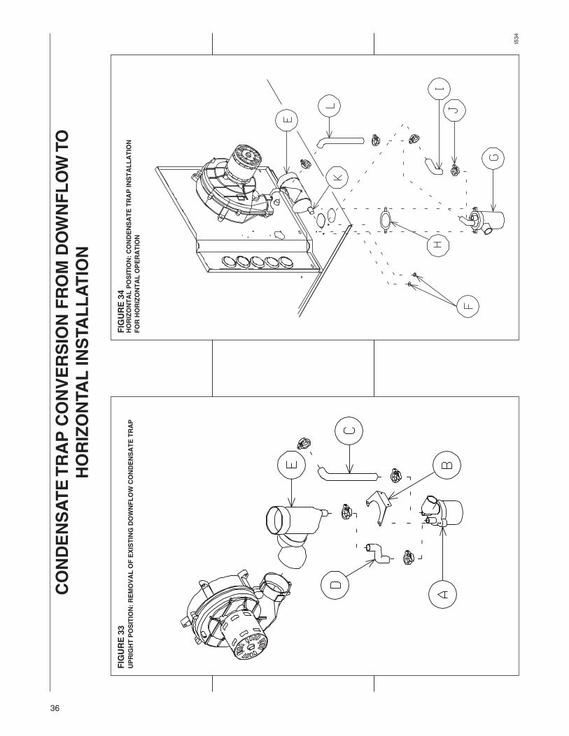
36
FIGURE33
UPRIGHTPOSITION:REMOVALOFEXISTINGDOWNFLOWCONDENSATETRAP
FIGURE34
HORIZONTALPOSITION:CONDENSATETRAPINSTALLATION
FORHORIZONTALOPERATION
I534
CONDENSATETRAPCONVERSIONFROMDOWNFLOWTO
HORIZONTALINSTALLATION

37
GAS SUPPLY AND PIPINGGAS SUPPLY
THIS FURNACE IS EQUIPPED ATTHE FACTORY FOR USE ONNATURAL GAS ONLY.CONVERSION TO LP GASREQUIRES A SPECIAL KIT ISAVAILABLE AT THEDISTRIBUTOR. FAILURE TO USETHE PROPER CONVERSION KITCAN CAUSE FIRE, CARBONMONOXIDE POISONING,EXPLOSION, PROPERTYDAMAGE, PERSONAL INJURY ORDEATH. See the conversion kitindex supplied with the furnace.This index identifies the proper LPGas Conversion Kit required foreach particular furnace.
IMPORTANT: Any additions,changes or conversions required forthe furnace to satisfactorily meet theapplication should be made by aqualified installer, service agency orthe gas supplier, using factory-specified or approved parts.
IMPORTANT: Connect this furnaceonly to gas supplied by a commercialutility.
IMPORTANT: U.L. or CSArecognized fuel gas and COdetector(s) are recommended in allapplications, and their installationshould be in accordance with themanufacturer’s recommendationsand/or local laws, rules, regulations orcustoms.
GAS PIPINGInstall the gas piping according to alllocal codes and regulations of theutility company.
If possible, run a separate gas supplyline directly from the meter to thefurnace. Consult the local gascompany for the location of themanual main shut-off valve. The gasline and manual gas stop must beadequate in size to prevent unduepressure drop and never smallerthan the pipe size to the gas valveon the furnace. Refer to Table 6 forthe recommended gas pipe size. SeeFigure 35 for typical gas pipeconnections.
Install a ground joint union within 3ft. of the cabinet to easily removethe gas valve assembly. Install amanual gas stop valve in the gasline outside the furnace casing.The manual gas stop should bereadily accessible to turn the gas
! WARNING
FIGURE 35GAS PIPING INSTALLATION
GROMMET
TOP VIEW OF GAS LINE AND VALVEIN OPT. POSITION
NOTE: WHEN GAS LINEIS IN OPT. POSITION,SWAP LOCATION OFGROMMET AND PLUG.
OPT. GAS LINEPOSITION
PLUG(IN NORMALPOSITION)
MANIFOLDPRESSURETAP
IGNITOR
MANIFOLD
GAS VALVEUNION
DRIP LEG
GROMMET(IN NORMALPOSITION)
4 TO 5 FEETABOVEFLOOR REQ’DBY SOMEUTILITIES.
MANUALGASSTOP
BURNERS
GROMMET
TOP VIEW OF GAS LINE AND VALVEIN OPT. POSITION
MANUALGASSTOP
4 TO 5 FEET ABOVEFLOOR REQ’D BYSOME UTILITIES.
GROMMET(IN NORMALPOSITION)
DRIP LEG
UNION
GAS VALVE
BURNERSMANIFOLD
IGNITOR
MANIFOLDPRESSURETAP
PLUG(IN NORMALPOSITION)
NOTE: WHEN GASLINE IS IN OPT.POSITION, SWAPLOCATION OFGROMMET ANDPLUG.
DOWNFLOW
I328
UPFLOW
MANUAL GAS STOP
UNION
DRIP LEG
BURNERS
MANIFOLD
GAS VALVEI524
IMPORTANT: DO NOT RUN A FLEXIBLE GAS CONNECTOR INSIDE THEUNIT. Extend the 1/2" black pipe from the gas valve to the outside of thecabinet.
HORIZONTAL

38
NEVER PURGE A GAS LINE INTOTHE COMBUSTION CHAMBER.NEVER USE MATCHES, FLAME ORANY IGNITION SOURCE FORCHECKING LEAKAGE. FAILURE TOADHERE TO THIS WARNING CANCAUSE A FIRE OR EXPLOSIONRESULTING IN PROPERTYDAMAGE, PERSONAL INJURY ORDEATH.
To check for gas leakage, use anapproved chloride-free soap and watersolution, or other approved method.
FIGURE 36TYPICAL GAS VALVE
GAS VALVE #60-101921-02
supply on or off. Install a drip leg inthe gas supply line as close to thefurnace as possible. Always use apipe compound resistant to the actionof liquefied petroleum gases on allthreaded connections.
IMPORTANT:When making gas pipeconnections, use a back-up wrench toprevent any twisting of the main gasvalve and manifold. Do notovertighten gas valve on pipe.
Any strains on the gas valve canchange the position of the gas orificesin the burners. This can cause erraticfurnace operation.
IMPORTANT: Do not run a flexiblegas connector inside the furnace. Thegas pipe gasket in the cabinet doesnot seal around a flexible gas line.
If local codes allow the use of aflexible gas appliance connector,always use a new listed connector.Do not use a connector which haspreviously serviced another gasappliance. Massachusetts lawrequires that all flexible connectors beless than 36”.
It is important to have all openingsin the cabinet burner compartmentsealed for proper furnaceoperation.
IMPORTANT: ENSURE that thefurnace gas valve not be subjected tohigh gas line supply pressures.
DISCONNECT the furnace and itsindividual manual gas stop from thegas supply piping during anypressure testing that exceeds 1/2PSIG. (3.48 kPa).
GAS PRESSURENatural gas supply pressure shouldbe 5" to 10.5" w.c. LP gas supplypressure should be 11" to 13" w.c.This pressure must be maintainedwith all other gas-fired appliancesin operation.
The minimum gas supply pressure tothe gas valve for proper furnace inputadjustments is 5" w.c. for natural gas,however 6" to 7" is recommended.The minimum gas supply pressure is11" w.c. for LP gas.
ELEVATIONS ABOVE 2000 FTREQUIRE THAT THE FURNACEINPUT RATING BE ADJUSTED ANDTHAT THE SIZE OF THE BURNERORIFICES BE RE-CALCULATEDBASED ON ELEVATION AND GASHEATING VALUE. THE BURNERORIFICES MAY (OR MAY NOT)NEED TO BE CHANGED. SEE THESECTION TITLED “HIGH ALTITUDEINSTALLATIONS” OF THIS BOOKFOR INSTRUCTIONS.
! WARNING
TABLE 6NATURAL GAS PIPE CAPACITY TABLE (CU. FT./HR.)
Capacity of gas pipe of different diameters and lengths in cu. ft. per hr. with pressure drop of 0.3 in. and specificgravity of 0.60 (natural gas).
Nominal Length of Pipe, FeetIron PipeSize, Inches 10 20 30 40 50 60 70 80
1/2 132 92 73 63 56 50 46 433/4 278 190 152 130 115 105 96 901 520 350 285 245 215 195 180 170
1-1/4 1,050 730 590 500 440 400 370 3501-1/2 1,600 1,100 890 760 670 610 560 530
After the length of pipe has been determined, select the pipe size which will provide the minimum cubic feet per hourrequired for the gas input rating of the furnace. By formula:
Gas Input of Furnace (BTU/HR)Cu. Ft. Per Hr. Required = Heating Value of Gas (BTU/FT3)The gas input of the furnace is marked on the furnace rating plate. The heating value of the gas (BTU/FT3) may bedetermined by consulting the local natural gas utility or the LP gas supplier.
GAS VALVEThis furnace has a 24-volt gas valve.It has ports for measuring supply andmanifold gas pressure. The valvebody contains a pressure regulator tomaintain proper manifold gaspressure.
A control switch is on the valve body.It can be set to only the “ON” or“OFF” positions. The gas valve is aslow-opening valve. See Figure 36.
When energized, it takes 6 to 8seconds to fully open.
CAUTION!
GAS CONTROLSWITCH
INLETPRESSURETAP
OUTLETPRESSURETAP
LOW FIREMANIFOLDPRESSUREADJUSTMENT
HIGH FIREMANIFOLDPRESSUREADJUSTMENT

39
TABLE 7
LP CONVERSIONIMPORTANT: LP gas from trucksused to transport liquid-basedfertilizers can contain chemicals thatwill damage the furnace. Verify thatyour gas supplier does not use thesame truck to transport materialsother than LP.
For LP conversion, a new gas valve isrequired. The new gas valve isincluded in the LP kit. The correct LPorifices should be selected based onthe altitude of the installation (seechart below). Orifices included in thekit are for sea level to 2000 ft.(1.15mm) and 3000 to 4000 ft.(1.10mm) The LP Gas Valve Kit isFP19. Orifices for elevations 4000 ft.and above must be ordered. Refer toTable 7.
ELEVATIONS ABOVE 2000 FTREQUIRE THAT THE FURNACEINPUT RATING BE ADJUSTEDAND THAT THE SIZE OF THEBURNER ORIFICES BE RE-CALCULATED BASED ONELEVATION AND GAS HEATINGVALUE. THE BURNER ORIFICESMAY (OR MAY NOT) NEED TO BECHANGED. SEE THE SECTIONTITLED “HIGH ALTITUDEINSTALLATIONS” OF THIS BOOKFOR INSTRUCTIONS.
NOTE: Furnace conversion to LP gasmust be performed by a qualifiedinstaller, service agency or the gassupplier.
To change the gas valve and orificespuds for either conversion to LP or forelevation:
1. Shut off the manual main gas valveand remove the gas manifold.
2. Replace the orifice spuds.
3. For LP conversion ONLY, Removethe gas valve.
4. Reassemble in reverse order. InLP applications, use the new gasvalve provided in the LPconversion kit.
5. Attach the notice label alerting thenext service technician that thefurnace has been converted to LPgas.
6. Turn the gas supply back on andcheck for proper operation, leaksand manifold pressure. SeeFigures 37 and 39.
NOTE: Orifices in the kit are sized for aheating value of 2500 BTU per cubic ft.for LP.
ORIFICE ORDERINGINFORMATIONOrifice sizes are selected by adding the2-digit drill size required in the orificepart number. Drill sizes available are 39through 64; metric sizes available1.10mm (-90) and 1.15mm (-91):
Orifice Part Number 62-22175-(drillsize)
Example 1:# 60 drill size orifice requiredPart # 62-22175-60
Example 2:1.15mm drill size orifice requiredPart # 62-22175-91
NOTE: Do not plug or drill out orifices.
BTU Input (per OrificeAltitude burner) 15000 Size
0 to 2000 ft. 15000 1.15 mm(factory)
2000’-3000’ 13200 1.15 mm
3000’-4000’ 12600 1.10 mm
4000’-5000’ 12000 #58
5000’-6000’ 11400 #59
6000’-7000’ 10800 #60
7000’-8000’ 10200 #62
8000’-9000’ 9600 #63
9000’-10000’ 9000 #64
SETTING GAS PRESSUREThe maximum gas supply pressureto the furnace should be 10.5" w.c.natural gas, or 13" w.c. LP gas. Theminimum supply gas pressure to thegas valve should be 5" w.c. naturalgas or 11" w.c. LP gas. A properlycalibrated U-Tube manometer isrequired for accurate gas pressuremeasurements.
ELEVATIONS ABOVE 2000 FTREQUIRE THAT THE FURNACEINPUT RATING BE ADJUSTEDAND THAT THE SIZE OF THEBURNER ORIFICES BE RE-CALCULATED BASED ONELEVATION AND GAS HEATINGVALUE. THE BURNER ORIFICESMAY (OR MAY NOT) NEED TO BECHANGED. SEE THE SECTIONTITLED “HIGH ALTITUDEINSTALLATIONS” OF THIS BOOKFOR INSTRUCTIONS.
Supply Gas Pressure Measure-ment. A line pressure tap is on theinput side of the gas valve. SeeFigure 37.
1. With gas shut off to the furnaceat the manual gas stop outsidethe unit, remove the inputpressure tap plug.
2. Connect a U-Tube manometer tothe pressure tap.
3. Turn on the gas supply andoperate the furnace and all othergas-fired units on the same gasline as the furnace.
4. Note or adjust the line gaspressure to give:
A. 5" - 10.5" w.c. for natural gas.
B. 11" - 13" w.c. for LP gas.
5. Shut off the gas at the manualgas stop and remove theU-Tube manometer.
6. Replace the pressure tap plugbefore turning on the gas. Turnon gas and check for leaks.
If the supply gas line pressure isabove these ranges, install an in-linegas regulator to the furnace fornatural gas units. With LP gas, havethe LP supplier reduce the linepressure at the regulator.
If supply gas line pressure is belowthese ranges, either remove anyrestrictions in the gas supply piping orenlarge the gas pipe. See Tables 6and 8. With LP gas, have the LPsupplier adjust the line pressure atthe regulator.
CAUTION!
CAUTION!

40
TABLE 8LP GAS PIPE CAPACITY TABLE (CU. FT./HR.)
Maximum capacity of pipe in thousands of BTU per hour of undiluted liquefied petroleum gases (at 11 inches watercolumn inlet pressure).(Based on a Pressure Drop of 0.5 Inch Water Column)
Nominal Length of Pipe, FeetIron PipeSize, Inches 10 20 30 40 50 60 70 80 90 100 125 150
1/2 275 189 152 129 114 103 96 89 83 78 69 633/4 567 393 315 267 237 217 196 182 173 162 146 1321 1,071 732 590 504 448 409 378 346 322 307 275 252
1-1/4 2,205 1,496 1,212 1,039 913 834 771 724 677 630 567 5111-1/2 3,307 2,299 1,858 1,559 1,417 1,275 1,181 1,086 1,023 976 866 7872 6,221 4,331 3,465 2,992 2,646 2,394 2,205 2,047 1,921 1,811 1,606 1,496
Example (LP): Input BTU requirement of unit, 120,000Equivalent length of pipe, 60 ft. = 3/4" IPS required.
FIGURE 37MANIFOLD PRESSURE TAP
Manifold Gas PressureMeasurement. Natural gasmanifold pressure should be 3.5"w.c.; LP gas manifold pressureshould be 10" w.c. Only smallvariations on gas pressure should bemade by adjusting the pressureregulator.
1. With the gas shut off at themanual gas stop, remove thepressure tap plug in the gasmanifold or the gas valve outlet.See Figure 37.
2. Connect a U-Tube manometer tothis pressure tap. See Figure 39.
3. Turn on the gas supply andoperate the furnace in high heatmode.
4. Note or adjust the manifold gaspressure to give:
A. 3.5" w.c. for natural gas highfire.
B. 10" w.c. for LP gas high fire.
5. To adjust the pressure regulatorfor high fire, remove the regulatorcap located on the side of theregulator. See Figure 38.
6. Turn the adjustment screwclockwise to increase pressure orcounterclockwise to decreasepressure.
7. Securely replace the regulatorcap for high fire.
8. Operate the furnace in lowspeed.
9. Note or adjust the manifoldpressure to give:
A. 1.7" w.c. for natural gas lowfire.
B. 4.8" w.c. for LP gas low fire.
10. To adjust the pressure regulatorfor low fire, remove the regulatorcap on the top of the regulator.See Figure 38.
11. Turn the adjustment screwclockwise to increase pressure orcounterclockwise to decreasepressure.
12. Securely replace the regulatorcap for low fire.
13. Verify pressures for high and lowfire operation.
14. Shut off gas at the manual gasvalve and remove the U-Tubemanometer.
15. Replace the manifold pressuretap plug before turning on gas.Check for leak.
MANIFOLDPRESSURETAP
FIGURE 38TYPICAL GAS VALVE
INLETPRESSURE TAP
OUTLETPRESSURETAP
HIGH FIREMANIFOLDPRESSUREADJUSTMENT
LOW FIREPRESSUREMANIFOLDADJUSTMENT
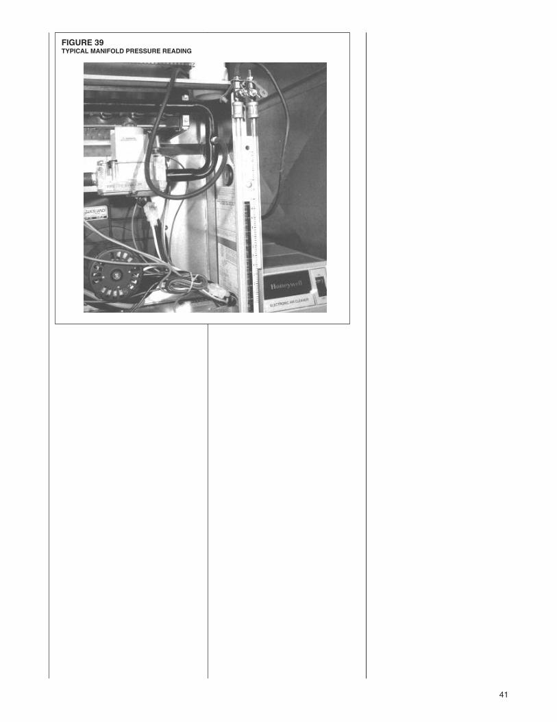
41
FIGURE 39TYPICAL MANIFOLD PRESSURE READING
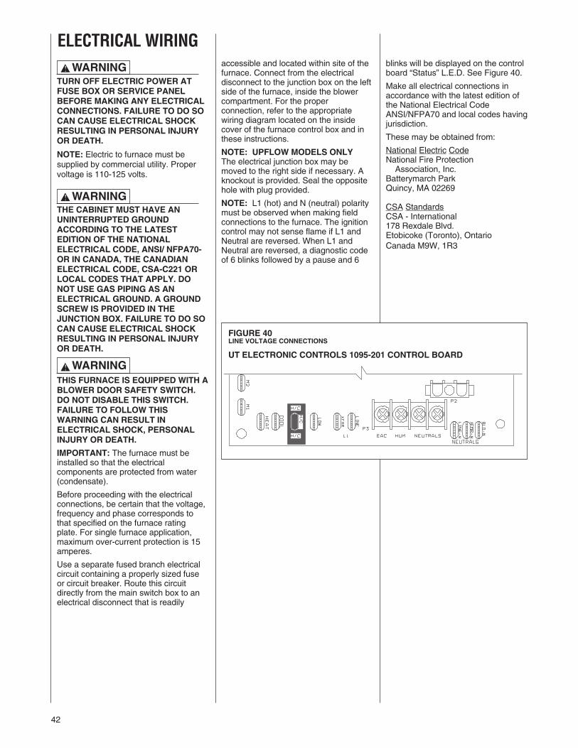
42
accessible and located within site of thefurnace. Connect from the electricaldisconnect to the junction box on the leftside of the furnace, inside the blowercompartment. For the properconnection, refer to the appropriatewiring diagram located on the insidecover of the furnace control box and inthese instructions.
NOTE: UPFLOW MODELS ONLYThe electrical junction box may bemoved to the right side if necessary. Aknockout is provided. Seal the oppositehole with plug provided.
NOTE: L1 (hot) and N (neutral) polaritymust be observed when making fieldconnections to the furnace. The ignitioncontrol may not sense flame if L1 andNeutral are reversed. When L1 andNeutral are reversed, a diagnostic codeof 6 blinks followed by a pause and 6
FIGURE 40LINE VOLTAGE CONNECTIONS
UT ELECTRONIC CONTROLS 1095-201 CONTROL BOARD
ELECTRICAL WIRING
TURN OFF ELECTRIC POWER ATFUSE BOX OR SERVICE PANELBEFORE MAKING ANY ELECTRICALCONNECTIONS. FAILURE TO DO SOCAN CAUSE ELECTRICAL SHOCKRESULTING IN PERSONAL INJURYOR DEATH.
NOTE: Electric to furnace must besupplied by commercial utility. Propervoltage is 110-125 volts.
THE CABINET MUST HAVE ANUNINTERRUPTED GROUNDACCORDING TO THE LATESTEDITION OF THE NATIONALELECTRICAL CODE, ANSI/ NFPA70-OR IN CANADA, THE CANADIANELECTRICAL CODE, CSA-C221 ORLOCAL CODES THAT APPLY. DONOT USE GAS PIPING AS ANELECTRICAL GROUND. A GROUNDSCREW IS PROVIDED IN THEJUNCTION BOX. FAILURE TO DO SOCAN CAUSE ELECTRICAL SHOCKRESULTING IN PERSONAL INJURYOR DEATH.
THIS FURNACE IS EQUIPPED WITH ABLOWER DOOR SAFETY SWITCH.DO NOT DISABLE THIS SWITCH.FAILURE TO FOLLOW THISWARNING CAN RESULT INELECTRICAL SHOCK, PERSONALINJURY OR DEATH.
IMPORTANT: The furnace must beinstalled so that the electricalcomponents are protected from water(condensate).
Before proceeding with the electricalconnections, be certain that the voltage,frequency and phase corresponds tothat specified on the furnace ratingplate. For single furnace application,maximum over-current protection is 15amperes.
Use a separate fused branch electricalcircuit containing a properly sized fuseor circuit breaker. Route this circuitdirectly from the main switch box to anelectrical disconnect that is readily
! WARNING
! WARNING
! WARNING
blinks will be displayed on the controlboard “Status” L.E.D. See Figure 40.
Make all electrical connections inaccordance with the latest edition ofthe National Electrical CodeANSI/NFPA70 and local codes havingjurisdiction.
These may be obtained from:
National Electric CodeNational Fire ProtectionAssociation, Inc.
Batterymarch ParkQuincy, MA 02269
CSA StandardsCSA - International178 Rexdale Blvd.Etobicoke (Toronto), OntarioCanada M9W, 1R3
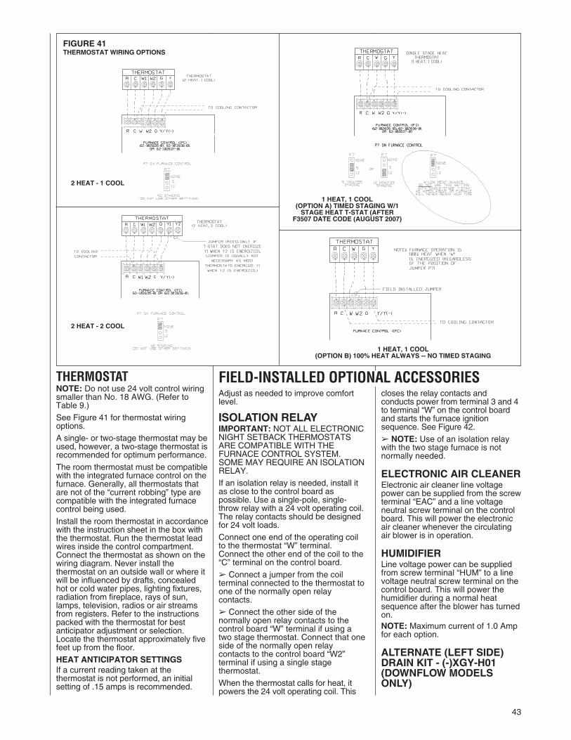
43
Adjust as needed to improve comfortlevel.
ISOLATION RELAYIMPORTANT: NOT ALL ELECTRONICNIGHT SETBACK THERMOSTATSARE COMPATIBLE WITH THEFURNACE CONTROL SYSTEM.SOME MAY REQUIRE AN ISOLATIONRELAY.If an isolation relay is needed, install itas close to the control board aspossible. Use a single-pole, single-throw relay with a 24 volt operating coil.The relay contacts should be designedfor 24 volt loads.Connect one end of the operating coilto the thermostat “W” terminal.Connect the other end of the coil to the“C” terminal on the control board.� Connect a jumper from the coilterminal connected to the thermostat toone of the normally open relaycontacts.� Connect the other side of thenormally open relay contacts to thecontrol board “W” terminal if using atwo stage thermostat. Connect that oneside of the normally open relaycontacts to the control board “W2”terminal if using a single stagethermostat.When the thermostat calls for heat, itpowers the 24 volt operating coil. This
closes the relay contacts andconducts power from terminal 3 and 4to terminal “W” on the control boardand starts the furnace ignitionsequence. See Figure 42.� NOTE: Use of an isolation relaywith the two stage furnace is notnormally needed.
ELECTRONIC AIR CLEANERElectronic air cleaner line voltagepower can be supplied from the screwterminal “EAC” and a line voltageneutral screw terminal on the controlboard. This will power the electronicair cleaner whenever the circulatingair blower is in operation.
HUMIDIFIERLine voltage power can be suppliedfrom screw terminal “HUM” to a linevoltage neutral screw terminal on thecontrol board. This will power thehumidifier during a normal heatsequence after the blower has turnedon.NOTE: Maximum current of 1.0 Ampfor each option.
ALTERNATE (LEFT SIDE)DRAIN KIT - (-)XGY-H01(DOWNFLOW MODELSONLY)
FIELD-INSTALLED OPTIONAL ACCESSORIESTHERMOSTATNOTE: Do not use 24 volt control wiringsmaller than No. 18 AWG. (Refer toTable 9.)See Figure 41 for thermostat wiringoptions.A single- or two-stage thermostat may beused, however, a two-stage thermostat isrecommended for optimum performance.The room thermostat must be compatiblewith the integrated furnace control on thefurnace. Generally, all thermostats thatare not of the “current robbing” type arecompatible with the integrated furnacecontrol being used.Install the room thermostat in accordancewith the instruction sheet in the box withthe thermostat. Run the thermostat leadwires inside the control compartment.Connect the thermostat as shown on thewiring diagram. Never install thethermostat on an outside wall or where itwill be influenced by drafts, concealedhot or cold water pipes, lighting fixtures,radiation from fireplace, rays of sun,lamps, television, radios or air streamsfrom registers. Refer to the instructionspacked with the thermostat for bestanticipator adjustment or selection.Locate the thermostat approximately fivefeet up from the floor.HEAT ANTICIPATOR SETTINGSIf a current reading taken at thethermostat is not performed, an initialsetting of .15 amps is recommended.
FIGURE 41THERMOSTAT WIRING OPTIONS
2 HEAT - 1 COOL
2 HEAT - 2 COOL
1 HEAT, 1 COOL(OPTION A) TIMED STAGING W/1STAGE HEAT T-STAT (AFTER
F3507 DATE CODE (AUGUST 2007)
1 HEAT, 1 COOL(OPTION B) 100% HEAT ALWAYS -- NO TIMED STAGING

44
FURNACETWINNINGINSTALLATIONSNOTE: Run furnaces as individualfurnaces before trying to twin or whentroubleshooting.Twinning operation of two furnaces,installed side-by-side, connected by acommon duct system with main powersupplied by the same source, andcontrolled by a common thermostat canbe done with the UT Electronic Controls1095-204 integrated control boards.� Only twin identical furnaces withidentical control boards.
� Furnaces must have same heatingand blower capacity.
� Only bottom returns can be used.(Upflow models only)
� No more than two furnaces (a pair)can share the same supply andreturn.
NOTE: Duct system must be adequateto provide correct airflow to eachfurnace for supply and return.
IMPORTANT: Twinning furnaces mustoperate off the same phase of power.
It should be noted that both blowers willrun simultaneously when there is a callfor heating, cooling or fan.The status LED will display blink code 5if twinning is not set up properly (refer toTroubleshooting diagram in the back ofthis manual).
IMPORTANT: Only two furnaces on asingle thermostat.
UT ELECTRONIC CONTROLS1095-201 or 204
TWO-STAGE TWINNING OPERATIONUSING A SINGLE-STAGETHERMOSTATA two-stage thermostat will give themost optimum performance. Thefurnace (when twinned) can operateusing a single-stage thermostat.
OPTION A: To run both units togetheras a single-stage furnace with NOstaging (100% high heat always) wirethe two furnaces together as shown inFigure 43.
Both controls must have jumper P6 inthe “TWIN” position (see Figure 48).
Both controls must have jumper P7 inthe “5” or “7” position (see Figure 48).
OPTION B: Both controls must havejumper P6 in the “TWIN” position (seeFigure 48).
Both controls must have jumper P7 inthe “5” or “7” position (see Figure 48).
For the first fire or twelve minutes ofoperation, the furnace will run at lowfire. If the thermostat does not satisfyin fire or twelve minutes, the furnaceswill automatically switch to high fireand will run on high fire until thethermostat is satisfied. See Figure 43for the wiring diagram for thisconfiguration.
TWO-STAGE OPERATION(See Figure 45)a. Control board "ONE" is onfurnace connected to thethermostat.
b. The 24 VAC supply to bothcontrol boards must be inphase with each other.
c. Connect the "C," "W1," “W2,”“Y,” and "TWIN" terminals tocounterparts on each control.
d. Both control boards must havejumper P6 in the “TWIN”position (see Figure 48).
Both controls must havejumper P7 in the “NONE”position (see Figure 48).
FIGURE 42ISOLATION RELAY
ST-A0804-01
TABLE 9FIELD WIRE SIZE FOR 24 VOLT CONTROL CIRCUITS
SOLID COPPER WIRE - AWG
3.0 16 14 12
2.5 16 14 12
2.0 18 16 14
50 100 150
LENGTH OF RUN - FEET �
� Wire length equals twice the run distanceNOTE: Do not use 24 volt control wiring smaller than No. 18.
THER
MOST
ATLO
AD-A
MPS

45
FIGURE 43UT Electronic Controls 1095-201 IFC, TWINNING CONNECTION -- SINGLE STAGE OPERATION

46
FIGURE 44UT ELECTRONIC CONTROLS 1095-202 CONTROL BOARD, TWINNING CONNECTION -- TWO-STAGE OPERATION
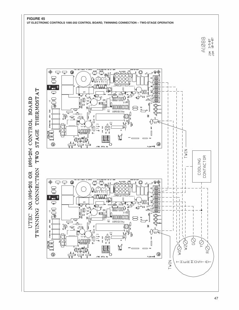
47
FIGURE 45UT ELECTRONIC CONTROLS 1095-202 CONTROL BOARD, TWINNING CONNECTION -- TWO-STAGE OPERATION
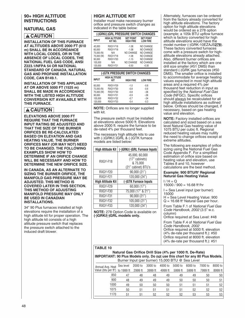
48
90+ HIGH ALTITUDEINSTRUCTIONS
NATURAL GAS
INSTALLATION OF THIS FURNACEAT ALTITUDES ABOVE 2000 FT (610m) SHALL BE IN ACCORDANCEWITH LOCAL CODES, OR IN THEABSENCE OF LOCAL CODES, THENATIONAL FUEL GAS CODE, ANSIZ223.1/NFPA 54 OR NATIONALSTANDARD OF CANADA, NATURALGAS AND PROPANE INSTALLATIONCODE, CAN B149.1.
INSTALLATION OF THIS APPLIANCEAT OR ABOVE 5000 FT (1525 m)SHALL BE MADE IN ACCORDANCEWITH THE LISTED HIGH ALTITUDECONVERSION KIT AVAILABLE WITHTHIS FURNACE.
ELEVATIONS ABOVE 2000 FTREQUIRE THAT THE FURNACEINPUT RATING BE ADJUSTED ANDTHAT THE SIZE OF THE BURNERORIFICES BE RE-CALCULATEDBASED ON ELEVATION AND GASHEATING VALUE. THE BURNERORIFICES MAY (OR MAY NOT) NEEDTO BE CHANGED. THE FOLLOWINGEXAMPLES SHOW HOW TODETERMINE IF AN ORIFICE CHANGEWILL BE NECESSARY AND HOW TODETERMINE THE NEW ORIFICE SIZE.
IN CANADA, AS AN ALTERNATE TOSIZING THE BURNER ORIFICE, THEMANIFOLD GAS PRESSURE MAY BEADJUSTED. THIS METHOD ISCOVERED LATER IN THIS SECTION.THIS METHOD OF ADJUSTINGMANIFOLD PRESSURE MAY ONLYBE USED IN CANADIANINSTALLATIONS.
34" 90 Plus furnaces installed at highelevations require the installation of ahigh altitude kit for proper operation. Thehigh altitude kit consists of a highaltitude pressure switch that replacesthe pressure switch attached to theinduced draft blower.
The pressure switch must be installedat elevations above 5000 ft. Elevationsabove 2000 ft. require the furnace to bede-rated 4% per thousand feet.The necessary high altitude kits to usewith (-)GRK/(-)GRL & (-)GTK furnacemodels are listed below:
NOTE: 278 Option Code is available on(-)GRK/(-)GRL models only.
! CAUTION
! CAUTION
Natural Gas Orifice Drill Size (4% per 1000 ft. De-Rate)IMPORTANT: 90 Plus Models only. Do not use this chart for any 80 Plus Models.
Burner Input (per burner) 15,000 BTU @ Sea LevelSea level 2000 to 3000 to 4000 to 5000 to 6000 to 7000 to 8000 toto 1999 ft 2999 ft 3999 ft 4999 ft 5999 ft 5999 ft 7999 ft 8999 ft
47 48 48 49 49 49 50 5048 49 49 49 50 50 50 5149 50 50 50 51 51 51 5250 51 51 51 51 52 52 5251 51 52 52 52 53 53 53
Annual Avg. HeatValue (btu per ft3)
850900
100010751170
TABLE 10
High Altitude Kit (-)GRK/(-)GRL Furnace Inputs
45,000, 60,000(17” cabinets)
RXGY-F18 & 75,000(21” cabinet) BTU’s
RXGY-F20 90,000 (21”)RXGY-F21 120,000 (24”)
High Altitude Kit (-)GTK Furnace InputsRXGY-F29 60,000 (17”)RXGY-F30 75,000 (17” & 21”)RXGY-F31 90,000 (21”)RXGY-F32 105,000 (21”)RXGY-F33 120,000 (24”)
HIGH ALTITUDE KITInstaller must make necessary burnerorifice and pressure switch changes asindicated in the table below:
(-)GRK/(-)GRL PRESSURE SWITCH CHANGES
INPUTHIGH ALTITUDE SET POINT SET POINT
KIT NO. HIGH FIRE LOW FIRE
45,000 RXGY-F18 -1.08 NO CHANGE60,000 RXGY-F18 -1.08 NO CHANGE75,000 (N) N/A NO CHANGE NO CHANGE75,000 (W) RXGY-F18 -1.08 NO CHANGE90,000 RXGY-F20 -1.15 NO CHANGE105,000 N/A NO CHANGE NO CHANGE120,000 RXGY-F21 -0.50 -0.30
(-)GTK PRESSURE SWITCH CHANGES
INPUTHIGH ALTITUDE
KIT HIGH FIRE LOW FIRE
60,000 RXGY-F29 -1.0 -0.875,000 (N) RXGY-F30 -0.8 -0.675,000 (W) RXGY-F30 -0.8 -.0690,000 RXGY-F31 -0.9 -.06105,000 RXGY-F32 -0.7 -.04120,000 RXGY-F33 -0.4 -0.3
NOTE: Orifices are no longer suppliedwith kit.
Alternately, furnaces can be orderedfrom the factory already converted forhigh altitude elevations. The factoryoption for high altitude elevationswould be ordered as a 278 option(example; a 105k BTU upflow furnacewhich is factory converted for highaltitude elevations would have themodel number (-)GRK-10EZAJS278).These factory converted furnacescome with a pressure switch for high-altitude elevations already attached.Also, different burner orifices areinstalled at the factory which are onedrill size smaller (#51 DMS) thanstandard (-)GRK gas furnaces (#50DMS). The smaller orifice is installedto accommodate for average heatingvalues expected in most high altitudeareas and a required 4% perthousand feet reduction in input asspecified by the National Fuel GasCode (NFGC). Specific orificesshould always be recalculated for allhigh altitude installations as outlinedbelow. Orifices should be changed, ifnecessary, based on gas heatingvalue and elevation.NOTE: Factory installed orifices arecalculated and sized based on a sealevel Natural Gas heating value of1075 BTU per cubic ft. Regionalreduced heating values may nullifythe need to change orifices except atextreme altitudes.The following are examples of orificesizing using the National Fuel GasCode Appendix F. For a simplifiedestimation of orifice size based onheating value and elevation, useTables 8 and 10, howevercalculations are the best method.Example: 900 BTU/ft3 RegionalNatural Gas Heating ValueI / H = Q15000 / 900 = 16.68 ft3/hr
I = Sea Level input (per burner):15000H = Sea Level Heating Value: 900Q = 16.68 ft3 Natural Gas per hour.
From Table F.1 of National Fuel GasCode Handbook, 2002 (3.5” w.c.column)Orifice required at Sea Level: #48
From Table F.4 of National Fuel GasCode Handbook, 2002Orifice required at 5000 ft. elevation(4% de-rate per thousand ft.): #50Orifice required at 8000 ft. elevation(4% de-rate per thousand ft.): #51

49
TABLE11
SUPPLEMENTALORIFICESIZECHART
90PlusONLYmodelswith15,000Btu'sperBurner.DONOTUSETHISCHARTFORANY80PLUSMODEL.
NATURALGASQUICKREFERENCECHARTFORORIFICESELECTION,AT3.5"W.C.ANDAPPROXIMATEFINALFIRINGRATES
FinalFiringRateperBurner
Sea
Level
Orifice
Size
SeaLevel
Cubic
Footat
3.5"W.C.
90PlusHeat
Valueat
15,000Btu’s
perBurner
0-999
1000-1999
2000-2999
3000-3999
4000-4999
5000-5999
6000-6999
7000-7999
8000-8999
9000-9999
ELEVATIONCHART(NFGrecommendedorificebasedon4%
derateforeach1000footofelevation,based
ontheintersectionoftheorificerequiredatSeaLevelandtheelevationrequiredbelow)
4618.57
808
4646
4747
4748
4849
4950
4717.52
856
4747
4848
4949
4950
5051
4816.36
917
4848
4949
4950
5050
5151
4915.2
987
4949
5050
5051
5151
5252
5013.92
1078
5050
5151
5151
5252
5253
5112.77
1175
5151
5152
5252
5253
5353
15,000
14,400
13,800
13,200
12,600
12,000
11,400
10,800
10,200
9,600
Allcalculationsareperformed
byusingthefirstthreecolumnsofinformationonly.Beforebeginninganycalculations,determinethe
individualburnerBtusizeandheatingvalueatSeaLevelfortheinstallationsite.EachvalueshownintheHeatValuecolumnisper
burnerat3.5"W.C.
NOTE:
HeatValueatSeaLevel,forthelocationoftheinstallation,isavailablefrom
theNaturalGasSuppliertothatsite.Orificesforallaltitudesarebased
onSeaLevelvalues.
Dividetheindividualburnercapacity(15,000for90plus)bytheHeatValueforthesitetodeterminetheCubicFootvalueatSeaLevel,ordivide
burnercapacitybytheCubicFootvaluefortheHeatValue.OnceyouhaveeithertheCubicFootValueortheHeatValueyoucanestimatetheSea
Levelorificeforthesite.Toselectthecorrespondinghighaltitudeorifice,locatethesiteelevationonthechartaboveandtheorificerequiredatSea
Levelfromyourcalculationinthefirstcolumn.Thecorrecthighaltitudeorificethatmustbeinstalledineachindividualburneristheintersectionof
thesetwopointsonthechartabove.
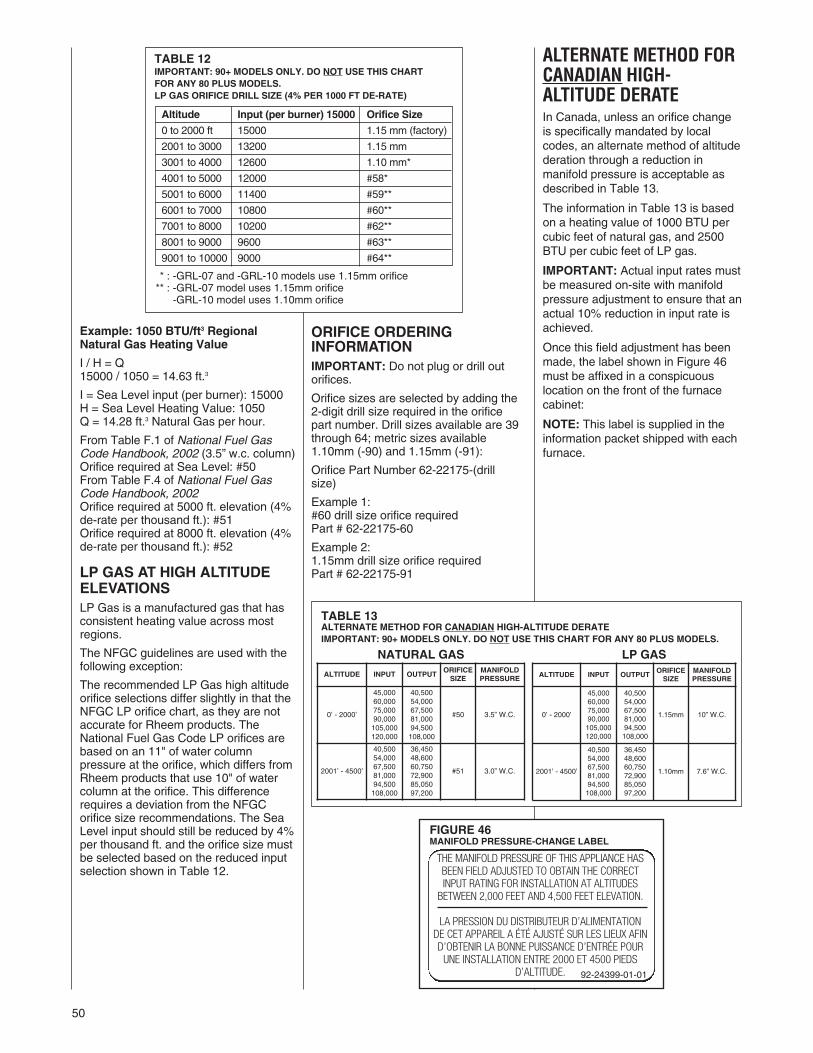
50
Example: 1050 BTU/ft3 RegionalNatural Gas Heating Value
I / H = Q15000 / 1050 = 14.63 ft.3
I = Sea Level input (per burner): 15000H = Sea Level Heating Value: 1050Q = 14.28 ft.3 Natural Gas per hour.
From Table F.1 of National Fuel GasCode Handbook, 2002 (3.5” w.c. column)Orifice required at Sea Level: #50From Table F.4 of National Fuel GasCode Handbook, 2002Orifice required at 5000 ft. elevation (4%de-rate per thousand ft.): #51Orifice required at 8000 ft. elevation (4%de-rate per thousand ft.): #52
LP GAS AT HIGH ALTITUDEELEVATIONSLP Gas is a manufactured gas that hasconsistent heating value across mostregions.
The NFGC guidelines are used with thefollowing exception:
The recommended LP Gas high altitudeorifice selections differ slightly in that theNFGC LP orifice chart, as they are notaccurate for Rheem products. TheNational Fuel Gas Code LP orifices arebased on an 11" of water columnpressure at the orifice, which differs fromRheem products that use 10" of watercolumn at the orifice. This differencerequires a deviation from the NFGCorifice size recommendations. The SeaLevel input should still be reduced by 4%per thousand ft. and the orifice size mustbe selected based on the reduced inputselection shown in Table 12.
ORIFICE ORDERINGINFORMATIONIMPORTANT: Do not plug or drill outorifices.
Orifice sizes are selected by adding the2-digit drill size required in the orificepart number. Drill sizes available are 39through 64; metric sizes available1.10mm (-90) and 1.15mm (-91):
Orifice Part Number 62-22175-(drillsize)
Example 1:#60 drill size orifice requiredPart # 62-22175-60
Example 2:1.15mm drill size orifice requiredPart # 62-22175-91
ALTERNATE METHOD FORCANADIAN HIGH-ALTITUDE DERATEIn Canada, unless an orifice changeis specifically mandated by localcodes, an alternate method of altitudederation through a reduction inmanifold pressure is acceptable asdescribed in Table 13.
The information in Table 13 is basedon a heating value of 1000 BTU percubic feet of natural gas, and 2500BTU per cubic feet of LP gas.
IMPORTANT: Actual input rates mustbe measured on-site with manifoldpressure adjustment to ensure that anactual 10% reduction in input rate isachieved.
Once this field adjustment has beenmade, the label shown in Figure 46must be affixed in a conspicuouslocation on the front of the furnacecabinet:
NOTE: This label is supplied in theinformation packet shipped with eachfurnace.
TABLE 12IMPORTANT: 90+ MODELS ONLY. DO NOT USE THIS CHARTFOR ANY 80 PLUS MODELS.LP GAS ORIFICE DRILL SIZE (4% PER 1000 FT DE-RATE)
Altitude Input (per burner) 15000 Orifice Size
0 to 2000 ft 15000 1.15 mm (factory)
2001 to 3000 13200 1.15 mm
3001 to 4000 12600 1.10 mm*
4001 to 5000 12000 #58*
5001 to 6000 11400 #59**
6001 to 7000 10800 #60**
7001 to 8000 10200 #62**
8001 to 9000 9600 #63**
9001 to 10000 9000 #64**
FIGURE 46MANIFOLD PRESSURE-CHANGE LABEL
TABLE 13ALTERNATE METHOD FOR CANADIAN HIGH-ALTITUDE DERATEIMPORTANT: 90+ MODELS ONLY. DO NOT USE THIS CHART FOR ANY 80 PLUS MODELS.
NATURAL GAS LP GAS
ALTITUDE INPUT OUTPUTORIFICESIZE
MANIFOLDPRESSURE
0’ - 2000’
45,00060,00075,00090,000105,000120,000
40,50054,00067,50081,00094,500108,000
#50 3.5” W.C.
2001’ - 4500’
40,50054,00067,50081,00094,500108,000
36,45048,60060,75072,90085,05097,200
#51 3.0” W.C.
ALTITUDE INPUT OUTPUTORIFICESIZE
MANIFOLDPRESSURE
0’ - 2000’
45,00060,00075,00090,000105,000120,000
40,50054,00067,50081,00094,500108,000
1.15mm 10” W.C.
2001’ - 4500’
40,50054,00067,50081,00094,500108,000
36,45048,60060,75072,90085,05097,200
1.10mm 7.6” W.C.
THE MANIFOLD PRESSURE OF THIS APPLIANCE HASBEEN FIELD ADJUSTED TO OBTAIN THE CORRECTINPUT RATING FOR INSTALLATION AT ALTITUDES
BETWEEN 2,000 FEET AND 4,500 FEET ELEVATION.
LA PRESSION DU DISTRIBUTEUR D’ALIMENTATIONDE CET APPAREIL A ÉTÉ AJUSTÉ SUR LES LIEUX AFIND’OBTENIR LA BONNE PUISSANCE D’ENTRÉE POURUNE INSTALLATION ENTRE 2000 ET 4500 PIEDS
D’ALTITUDE. 92-24399-01-01
** : -GRL-07 and -GRL-10 models use 1.15mm orifice** : -GRL-07 model uses 1.15mm orifice** : -GRL-10 model uses 1.10mm orifice

51
START-UP PROCEDURESDIRECT SPARK IGNITIONLIGHTING INSTRUCTIONSThis appliance is equipped with a directspark ignition device. This device lightsthe main burners each time the roomthermostat (closes) calls for heat. Seelighting instructions on the furnace.
During initial start-up, it is not unusualfor odor or smoke to come out of anyroom registers. It is recommended toensure proper ventilation by openingwindows and doors, before initial firing.
The furnace has a negative pressureswitch that is a safety during a call forheat. The induced draft blower must pulla negative pressure on the heatexchanger to close the negativepressure switch. The induced draftblower must maintain at least thenegative pressure switch set point forthe furnace to operate. If the induceddraft blower fails to close or maintain theclosing of the negative pressure switch,a “no heat call” would result.
TO START FURNACE1. BE SURE THAT THE MANUAL GASSTOP HAS BEEN IN THE “OFF”POSITION FOR AT LEAST FIVEMINUTES. DO NOT ATTEMPT TOMANUALLY LIGHT THE MAINBURNERS. FAILURE TO FOLLOWTHIS WARNING CAN CAUSE AFIRE OR AN EXPLOSIONRESULTING IN PROPERTYDAMAGE, PERSONAL INJURY ORDEATH.
2. Set the room thermostat to the lowestsetting.
3. Remove furnace panel.4. Turn the gas control knob to the “ON”position, or set the gas control switchto the “ON” position.
5. Securely replace furnace panel.6. Turn on the manual gas stop and theelectrical power.
7. Set the room thermostat to “Heat”and adjust to desired roomtemperature.
8. Complete installation checklist.
SHOULD OVERHEATING OCCUR ORTHE GAS SUPPLY FAIL TO SHUTOFF, SHUT OFF THE MANUAL GASSTOP TO THE APPLIANCE BEFORESHUTTING OFF THE ELECTRICALSUPPLY. FAILURE TO DO SO CANCAUSE AN EXPLOSION OR FIRERESULTING IN PROPERTY DAMAGE,PERSONAL INJURY OR DEATH.
IGNITOR PLACEMENT,ALIGNMENT & LOCATIONIgnition failure may be a result ofimproper ignitor alignment caused duringa service call or other work done to thefurnace in the field. When performing anywork on the burner, heat exchanger, etc.,the technician must check alignment ofthe spark ignitor. Misalignment of theignitor could cause a failure to light orrough ignition. The correct ignitoralignment is shown in Figure 47.
Sequence of operation with a singlestage heat thermostatNOTE: Single-stage operation isdetermined by the position of the jumperat position P7 of the control board.Options are 5 minutes between first andsecond stage or 12 minutes betweenfirst and second stage (see Figure 48).Do not leave jumper at P7 in the“NONE” position when using a single-stage thermostat with the timed stagingfeature. If the jumper is left on “NONE”,the furnace will never reach high heat(100% heat).For single-stage operation, “W” from thethermostat must be connected to “W”on the furnace control.See the section of this book titled“Electrical Wiring – Thermostat” for awiring diagram showing how to connecta thermostat (see Figure 41).
a. Connect the “W” terminal on thethermostat to the “W” terminal onthe IFC. Do not connect any wireto “W” on IFC when using a single-stage thermostat.
b. When there is a call for heat, the“R” and “W2” contacts close andthe IFC runs a self check routine toverify that both of the pressureswitch contacts are open. The limitswitch contacts are constantlymonitored.
c. The induced draft motor starts onhigh until the low and highpressure switch contacts close (amaximum of 60 seconds), andthen runs for a 30-second pre-purge. After the 30-second pre-purge, the spark ignitor energizesand the high stage of the gas valveopens, lighting the burners.
d. After the gas valve energizes, theremote flame sensor must proveignition for one second using theprocess of flame rectification. If theburners do not light or flame is notsensed, the system goes throughanother ignition sequence. It doesthis up to 4 times.
e. The IBM starts on low speed 20seconds after the burners light andflame is sensed. The induced draftmotor and gas valve switch to lowspeed. The furnace operates onlow fire for 12 minutes and then, ifthe thermostat is not satisfied,shifts to high fire, causing the draftinducer to go to high speed, thegas valve to 100% and the mainblower goes to high-fire heatingspeed.
f. When the thermostat cycle ends,the gas valve de-energizes, andthe burners go out.
g. The draft inducer will continuerunning for a 10 second postpurge.
h. The main blower will run for for theuser-defined blower-off delay (thistiming is field adjustable, for 90,120 150, or 180 seconds at
! WARNING
! WARNING
FIGURE 47UPFLOW OPTIMUM IGNITOR LOCATION DOWNFLOW/HORIZONTAL OPTIMUM IGNITOR LOCATION

52
Jumper P6 on the furnace controlboard). See Figure 48 for switchsettings.
Sequence if the system doesn’tlight or doesn’t sense flame:a. If flame is not sensed within 8seconds after the gas valveenergizes, the valve and the ignitorare de-energized. The induceddraft motor will, stop momentarily,and then restart to check PSoperation.
b. The ignition process goes throughthree more tries.
c. If there is no ignition after the fourthtrial, the furnace goes into softlockout for one hour.
d. The sequence repeats after a onehour delay and continues repeatinguntil ignition is successful or thecall for heat is terminated.
e. To reset the lockout, break powereither at the thermostat or at theunit disconnect switch for 30seconds. The furnace will then gothrough another set of trials forignition.
f. If flame is established andmaintained during the trial forignition period and flame is lost, thegas valve is de-energized, the draftinducer stops after a 10-secondpost-purge. The blower motor runsat the high-fire or low-fire heatingspeed (depending on state whenflame was lost) until it completesthe blower-off delay.When the blower-off delay is over,the control initiates another ignitiontrial period by starting the inducerfor the pre-purge. The control willrecycle up to 5 flame losses (4 re-cycles) within a single call for heatbefore going into lockout.
TO SHUT DOWN FURNACE1. Set the room thermostat to itslowest setting.
2. Shut off the gas to main burners bysetting the gas control switch to the“OFF” position, or by turning themanual gas stop closed.
Sequence of operation with twostage thermostatSee the section of this book titled“Electrical Wiring - Thermostat” for awiring diagram showing how toconnect a thermostat.Connect W1 on thermostat to W onIFC. Connect W2 on thermostat toW2 on IFC.Call for 1st stage heata. R and W thermostat contacts closeand the IFC runs a self checkroutine. After the IFC verifies thatboth sets of pressure switchcontacts are open, the induceddraft motor starts on high until bothpressure switch contacts close (amaximum of 60 seconds).
b. After a 30 second pre-purge thespark igniter energizes and the gasvalve (high stage) opens, lightingthe burners.
c. After the burners light, the remoteflame sensor must prove ignition. If
the burners do not light or flamecannot be proven, the system goesthrough another ignition sequence.It does this up to 4 times.
d. Twenty seconds after flame sense,the main blower energizes on lowspeed, the gas valve drops to lowfire, and the inducer drops to lowspeed. The furnace continues torun on low until the call for heat issatisfied or the second-stagecontacts close. If the first-stage callfor heat is satisfied the gas valvede-energizes and the induced draftmotor continues running for a 10second post purge time. The mainblower runs for the user-definedblower-off delay (this timing is fieldadjustable at Jumper P6). SeeFigure 48 for switch settings.
Call for 2nd stage heat after 1ststageR and W2 thermostat contacts close,calling for 2-stage heat. The induceddraft motor then switches to highspeed and the high pressure switchcontacts will close. The gas valveswitches to high fire and the mainblower switches to high-fire heatingspeed.
2nd stage heat satisfied, 1st stageheat still required.R and W2 thermostat contacts open(W1 to R remains closed). Theinduced draft motor switches to lowspeed, the main blower motorswitches to low-fire heating speedand the gas valve changes to low.The furnace continues to run in thismode until the first-stage heat call issatisfied. The system will shut downas noted in “d,” under first-stage callfor heat.Call for second-stage heat with noother existing heat call present.a-c. Same operation as call for first-
stage heat
d. Main blower starts on high speed20 seconds after gas valveenergizes. The furnace continuesto run on high until the W2contacts open. If W2 and W1open at the same time (both high& low stages are satisfied), thegas valve de-energizes and theinducer continues to run for a 10-second post-purge. The mainblower runs for the user selectedblower-off delay. See Figure 48for switch settings.
NOTE: Under certain conditions thefurnace may alternate between lowand high fire continuously. Thisoperation is based on demand fromthe thermostat and is controlled bythe thermostat. This operation isnormal and can be expected at timesto maintain optimum comfort.
SETTING BLOWER TIMINGThe UT ELECTRONIC CONTROLSIFC has four quick connect terminalsfor connecting the motor speedleads. These are:1. FAN SPEED/LOW — motor runs
on this speed when thethermostat is in the “FAN ON”position or when in low-fireheating speed heat.
2. COOL — connect desiredcooling speed.
3. HEAT — connect desired high-fire heating speed.
4. HEAT/COOL — connect desiredspeed when high heating andcooling speed are the same.
High fire and low fire blower timingare the same.IMPORTANT: Do not connect anymotor speeds to “HEAT” or “COOL” ifyou use the “HEAT/COOL” terminal.
FIGURE 48TWO-STAGE, 80 PLUS IFC JUMPER SELECTIONS
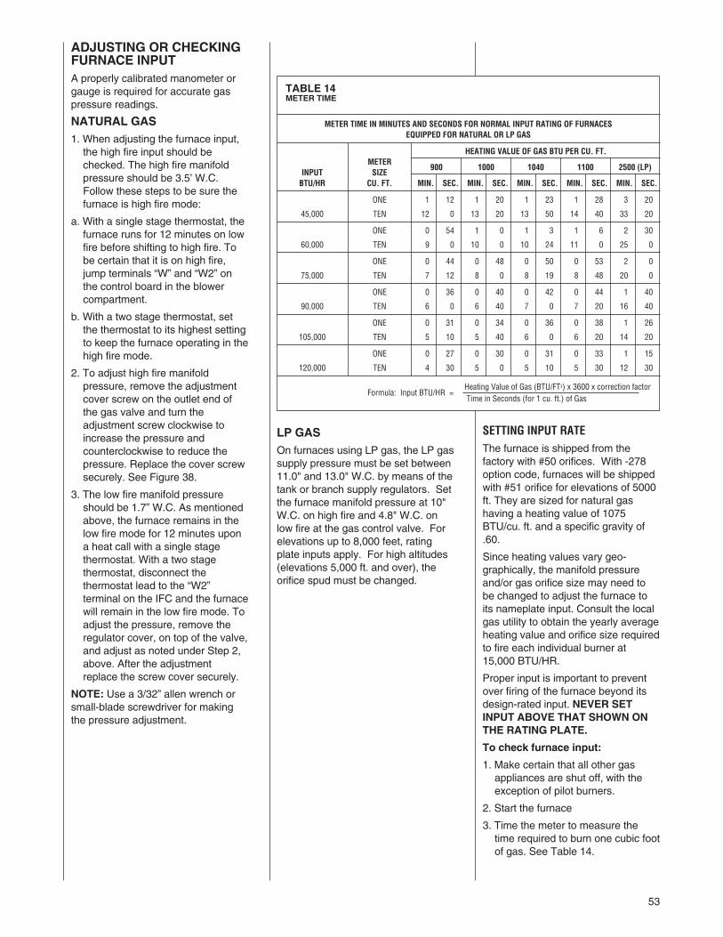
53
ADJUSTING OR CHECKINGFURNACE INPUTA properly calibrated manometer orgauge is required for accurate gaspressure readings.
NATURAL GAS1. When adjusting the furnace input,the high fire input should bechecked. The high fire manifoldpressure should be 3.5’ W.C.Follow these steps to be sure thefurnace is high fire mode:
a. With a single stage thermostat, thefurnace runs for 12 minutes on lowfire before shifting to high fire. Tobe certain that it is on high fire,jump terminals “W” and “W2” onthe control board in the blowercompartment.
b. With a two stage thermostat, setthe thermostat to its highest settingto keep the furnace operating in thehigh fire mode.
2. To adjust high fire manifoldpressure, remove the adjustmentcover screw on the outlet end ofthe gas valve and turn theadjustment screw clockwise toincrease the pressure andcounterclockwise to reduce thepressure. Replace the cover screwsecurely. See Figure 38.
3. The low fire manifold pressureshould be 1.7” W.C. As mentionedabove, the furnace remains in thelow fire mode for 12 minutes upona heat call with a single stagethermostat. With a two stagethermostat, disconnect thethermostat lead to the “W2”terminal on the IFC and the furnacewill remain in the low fire mode. Toadjust the pressure, remove theregulator cover, on top of the valve,and adjust as noted under Step 2,above. After the adjustmentreplace the screw cover securely.
NOTE: Use a 3/32” allen wrench orsmall-blade screwdriver for makingthe pressure adjustment.
LP GASOn furnaces using LP gas, the LP gassupply pressure must be set between11.0" and 13.0" W.C. by means of thetank or branch supply regulators. Setthe furnace manifold pressure at 10"W.C. on high fire and 4.8" W.C. onlow fire at the gas control valve. Forelevations up to 8,000 feet, ratingplate inputs apply. For high altitudes(elevations 5,000 ft. and over), theorifice spud must be changed.
SETTING INPUT RATEThe furnace is shipped from thefactory with #50 orifices. With -278option code, furnaces will be shippedwith #51 orifice for elevations of 5000ft. They are sized for natural gashaving a heating value of 1075BTU/cu. ft. and a specific gravity of.60.
Since heating values vary geo-graphically, the manifold pressureand/or gas orifice size may need tobe changed to adjust the furnace toits nameplate input. Consult the localgas utility to obtain the yearly averageheating value and orifice size requiredto fire each individual burner at15,000 BTU/HR.
Proper input is important to preventover firing of the furnace beyond itsdesign-rated input. NEVER SETINPUT ABOVE THAT SHOWN ONTHE RATING PLATE.
To check furnace input:
1. Make certain that all other gasappliances are shut off, with theexception of pilot burners.
2. Start the furnace
3. Time the meter to measure thetime required to burn one cubic footof gas. See Table 14.
TABLE 14METER TIME
METER TIME IN MINUTES AND SECONDS FOR NORMAL INPUT RATING OF FURNACESEQUIPPED FOR NATURAL OR LP GAS
HEATING VALUE OF GAS BTU PER CU. FT.METER
900 1000 1040 1100 2500 (LP)INPUT SIZEBTU/HR CU. FT. MIN. SEC. MIN. SEC. MIN. SEC. MIN. SEC. MIN. SEC.
ONE 1 12 1 20 1 23 1 28 3 20
45,000 TEN 12 0 13 20 13 50 14 40 33 20
ONE 0 54 1 0 1 3 1 6 2 30
60,000 TEN 9 0 10 0 10 24 11 0 25 0
ONE 0 44 0 48 0 50 0 53 2 0
75,000 TEN 7 12 8 0 8 19 8 48 20 0
ONE 0 36 0 40 0 42 0 44 1 40
90,000 TEN 6 0 6 40 7 0 7 20 16 40
ONE 0 31 0 34 0 36 0 38 1 26
105,000 TEN 5 10 5 40 6 0 6 20 14 20
ONE 0 27 0 30 0 31 0 33 1 15
120,000 TEN 4 30 5 0 5 10 5 30 12 30
Heating Value of Gas (BTU/FT3) x 3600 x correction factorFormula: Input BTU/HR =
Time in Seconds (for 1 cu. ft.) of Gas
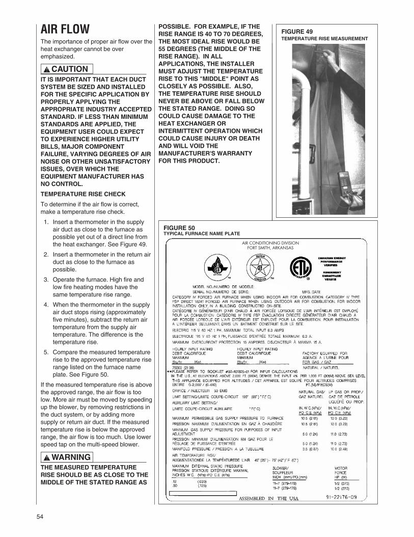
54
AIR FLOWThe importance of proper air flow over theheat exchanger cannot be overemphasized.
IT IS IMPORTANT THAT EACH DUCTSYSTEM BE SIZED AND INSTALLEDFOR THE SPECIFIC APPLICATION BYPROPERLY APPLYING THEAPPROPRIATE INDUSTRY ACCEPTEDSTANDARD. IF LESS THAN MINIMUMSTANDARDS ARE APPLIED, THEEQUIPMENT USER COULD EXPECTTO EXPERIENCE HIGHER UTILITYBILLS, MAJOR COMPONENTFAILURE, VARYING DEGREES OF AIRNOISE OR OTHER UNSATISFACTORYISSUES, OVER WHICH THEEQUIPMENT MANUFACTURER HASNO CONTROL.
TEMPERATURE RISE CHECK
To determine if the air flow is correct,make a temperature rise check.
1. Insert a thermometer in the supplyair duct as close to the furnace aspossible yet out of a direct line fromthe heat exchanger. See Figure 49.
2. Insert a thermometer in the return airduct as close to the furnace aspossible.
3. Operate the furnace. High fire andlow fire heating modes have thesame temperature rise range.
4. When the thermometer in the supplyair duct stops rising (approximatelyfive minutes), subtract the return airtemperature from the supply airtemperature. The difference is thetemperature rise.
5. Compare the measured temperaturerise to the approved temperature riserange listed on the furnace nameplate. See Figure 50.
If the measured temperature rise is abovethe approved range, the air flow is toolow. More air must be moved by speedingup the blower, by removing restrictions inthe duct system, or by adding moresupply or return air duct. If the measuredtemperature rise is below the approvedrange, the air flow is too much. Use lowerspeed tap on the multi-speed blower.
THE MEASURED TEMPERATURERISE SHOULD BE AS CLOSE TO THEMIDDLE OF THE STATED RANGE AS
FIGURE 49TEMPERATURE RISE MEASUREMENT
FIGURE 50TYPICAL FURNACE NAME PLATE
POSSIBLE. FOR EXAMPLE, IF THERISE RANGE IS 40 TO 70 DEGREES,THE MOST IDEAL RISE WOULD BE55 DEGREES (THE MIDDLE OF THERISE RANGE). IN ALLAPPLICATIONS, THE INSTALLERMUST ADJUST THE TEMPERATURERISE TO THIS "MIDDLE" POINT ASCLOSELY AS POSSIBLE. ALSO,THE TEMPERATURE RISE SHOULDNEVER BE ABOVE OR FALL BELOWTHE STATED RANGE. DOING SOCOULD CAUSE DAMAGE TO THEHEAT EXCHANGER ORINTERMITTENT OPERATION WHICHCOULD CAUSE INJURY OR DEATHAND WILL VOID THEMANUFACTURER'S WARRANTYFOR THIS PRODUCT.
! WARNING
! CAUTION
AIR CONDITIONING DIVISIONFORT SMITH, ARKANSAS
55
! WARNING
GAS FURNACE (DIRECTDRIVE) INSTRUCTIONSFOR CHANGING BLOWERSPEED
DISCONNECT THE ELECTRICALSUPPLY TO THE FURNACEBEFORE ATTEMPTING TOCHANGE THE BLOWER SPEED.FAILURE TO DO SO CAN CAUSEELECTRICAL SHOCK RESULTINGIN PERSONAL INJURY OR DEATH.
The blower motor is wired for blowerspeeds required for normal operationas shown.
If additional blower speed taps areavailable (leads connected to “M1”and “M2” on the IFC), speeds may bechanged if necessary to fitrequirements of the particularinstallation. Reconnect the unusedmotor leads to “M1” or “M2” on theIntegrated Furnace Control Board(IFC). Check motor lead color forspeed designation.
Heating speeds should not bereduced where it could cause thefurnace air temperature to rise toexceed the maximum outlet airtemperature specified for the unit.
IMPORTANT: Any combination ofmotor taps to the IFC can be usedprovided the temperature rise iswithin the specified range when inhigh or low heat and that there isenough airflow in the cooling mode.When changing the motor tapspeeds, the temperature rise must bechecked on both heat speeds andtemperature drop in cooling must bechecked again after the change ismade to ensure that the temperaturesare within the required specifiedranges.
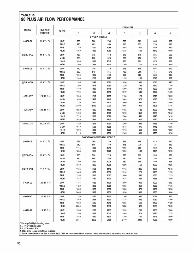
56
TABLE 15
90 PLUS AIR FLOW PERFORMANCE
CFM @ ESPMODEL BLOWER/ SPEED
MOTOR HP .1 .2 .3 .4 .5 .6 .7
UPFLOW MODELS
(-)GRL-04 11 X 7 / 1⁄2 LOW 805 780 760 720 685 645 605*M-LO 920 885 850 810 775 730 690M-HI 1140 1110 1085 1045 1010 950 890HIGH 1360 1320 1280 1235 1195 1140 1080
(-)GRL-07(A) 11 X 7 / 1⁄2 LOW 780 745 710 675 640 595 555M-LO 880 850 825 785 750 702 655*M-HI 1090 1050 1010 970 925 875 825HIGH 1300 1255 1210 1160 1110 1055 1005
(-)GRL-06 11 X 7 / 1⁄2 LOW 770 740 710 675 645 605 570*M-LO 880 845 815 790 760 715 670M-HI 1060 1025 990 960 925 880 835HIGH 1260 1215 1175 1135 1100 1040 985
(-)GRL-07(B) 12 X 7 / 3⁄4 LOW 1105 1095 1080 1050 1030 1010 990*M-LO 1290 1275 1260 1220 1195 1170 1140M-HI 1480 1435 1415 1390 1370 1300 1255HIGH 1705 1665 1615 1570 1540 1475 1400
(-)GRL-09** 12 X 11 / 3⁄4 LOW 1235 1210 1185 1150 1120 1075 1035M-LO 1490 1465 1440 1405 1375 1315 1255*M-HI 1720 1670 1620 1600 1580 1520 1460HIGH 2100 2050 2000 1955 1910 1825 1745
(-)GRL-10** 12 X 11 / 3⁄4 LOW 1230 1205 1180 1155 1130 1090 1050M-LO 1490 1445 1405 1375 1350 1295 1240*M-HI 1710 1665 1620 1580 1540 1475 1410HIGH 2010 1955 1900 1855 1810 1710 1610
(-)GRK-12** 11 X 10 / 3⁄4 LOW 1320 1305 1290 1260 1230 1185 1140M-LO 1610 1580 1555 1515 1475 1415 1355*M-HI 1870 1820 1775 1715 1660 1590 1520HIGH 2115 2050 1990 1945 1900 1795 1690
DOWNFLOW/HORIZONTAL MODELS
(-)GTK-06 11 X 7 / 1⁄2 LOW 795 760 730 695 660 615 570*M-LO 910 885 860 815 770 725 680M-HI 1115 1080 1045 1005 965 920 875HIGH 1365 1315 1270 1225 1180 1125 1070
(-)GTK-07(A) 11 X 7 / 1⁄2 LOW 780 750 720 675 635 595 555M-LO 890 860 835 790 750 705 660*M-HI 1100 1060 1025 980 940 890 845HIGH 1340 1295 1250 1200 1150 1090 1025
(-)GTK-07(B) 11 X 7 / 3⁄4 LOW 1185 1160 1140 1115 1095 1065 1040*M-LO 1405 1375 1350 1310 1270 1235 1195M-HI 1595 1560 1525 1480 1440 1380 1325HIGH 1835 1780 1730 1675 1625 1555 1480
(-)GTK-09 12 X 11 / 3⁄4 LOW 1155 1125 1100 1080 1060 1000 940*M-LO 1420 1400 1380 1365 1350 1260 1175M-HI 1605 1575 1550 1560 1570 1480 1390HIGH 2005 1965 1930 1890 1850 1765 1680
(-)GTK-10 12 X 11 / 3⁄4 LOW 1180 1150 1120 1100 1080 1025 970*M-LO 1460 1425 1390 1375 1360 1280 1200M-HI 1680 1645 1615 1585 1560 1490 1420HIGH 2055 2000 1940 1880 1820 1745 1675
(-)GTK-12 11 X 10 / 3⁄4 LOW 1285 1250 1215 1235 1260 1230 1200*M-HI 1590 1565 1540 1505 1475 1425 1375M-HI 1840 1820 1800 1750 1700 1645 1590HIGH 2315 2250 2185 2110 2040 1965 1890
* Factory-Set High Heating speedA = 17 1⁄2" Cabinet SizeB = 21" Cabinet SizeNOTE: Units tested with filters in place.**Where the maximum air flow is above 1800 CFM, we recommend both sides or 1 side and bottom to be used to maximize air flow.
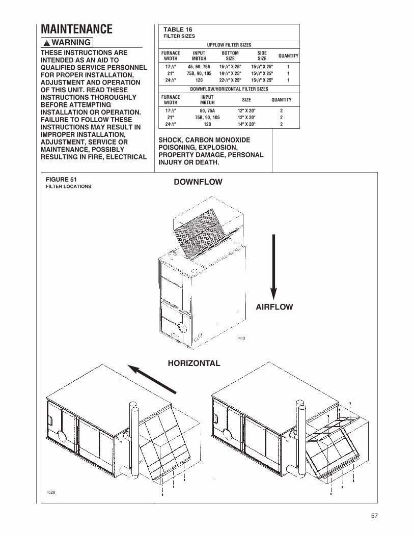
57
FIGURE 51FILTER LOCATIONS
I528
HORIZONTAL
I413
DOWNFLOW
AIRFLOW
HORIZONTAL
MAINTENANCE
THESE INSTRUCTIONS AREINTENDED AS AN AID TOQUALIFIED SERVICE PERSONNELFOR PROPER INSTALLATION,ADJUSTMENT AND OPERATIONOF THIS UNIT. READ THESEINSTRUCTIONS THOROUGHLYBEFORE ATTEMPTINGINSTALLATION OR OPERATION.FAILURE TO FOLLOW THESEINSTRUCTIONS MAY RESULT INIMPROPER INSTALLATION,ADJUSTMENT, SERVICE ORMAINTENANCE, POSSIBLYRESULTING IN FIRE, ELECTRICAL
SHOCK, CARBON MONOXIDEPOISONING, EXPLOSION,PROPERTY DAMAGE, PERSONALINJURY OR DEATH.
TABLE 16FILTER SIZES
UPFLOW FILTER SIZES
FURNACE INPUT BOTTOM SIDE QUANTITYWIDTH MBTUH SIZE SIZE
171/2" 45, 60, 75A 153/4" X 25" 153/4" X 25" 121" 75B, 90, 105 191/4" X 25" 153/4" X 25" 1241/2" 120 223/4" X 25" 153/4" X 25" 1
DOWNFLOW/HORIZONTAL FILTER SIZES
FURNACE INPUT QUANTITYWIDTH MBTUH SIZE
171/2" 60, 75A 12" X 20" 221" 75B, 90, 105 12" X 20" 2241/2" 120 14" X 20" 2
! WARNING

58
FIGURE 52BOTTOM PANEL REMOVALFILTER LOCATION
JACKET ASSEMBLY
REMOVESOLID BOTTOM
NOTE:BACK FLANGE OF SOLID BOTTOM FITSUNDERNEATH JACKET. SIDES AND FRONTFLANGES FIT OVER FLANGES ON JACKET.
SCREW(2) REQ’D.
JACKET ASSEMBLY
FILTER
SOLIDBOTTOM
FILTERROD
SOLID BOTTOM REMOVAL
FILTER & ROD LOCATION
FILTER AND ROD ASSEMBLY
ODS
FILTERSUPPORTANGLE
FILTER
FILTER ROD
JACKET
I332
I
FILTERROD45-24095-01
FILTER
FILTERSUPPORTANGLEAE-61883-01
FILTER RODSUPPORTANGLEAE-60520-01
JACKET
DRILL (2)3/16" DIA.HOLES
8.000
4.875
1.531
CUT-OUT AND DRILL DETAILR
JACKET
JACKET
ANGLE
FILTER RODSUPPORTANGLE
FILTER SUPPORTANGLE(SEE ANGLE DETAIL)
ATTACH WITHSHEET METALSCREWS (2 REQÕD)
ANGLE DETAIL
CROD & FILTER SUPPORT ANGLE ASSEMBLY
F
FILTER RODSUPPORTANGLEAE-60520-01
FILTER SUPPORTANGLE(SEE ANGLE DETAIL)AE-61883-01
UPFLOW BOTTOM RETURN
UPFLOW SIDE RETURN
AIRFLOW
AIRFLOW
SOLIDBOTTOM
NOTE: Use both side returns for 1800 CFM or more.
SOLIDBOTTOM
59
it is recommended that a qualifiedinstaller, service agency, or the gassupplier annually inspect the fluepassageways, the vent system andthe main burners for continued safeoperation. Pay particular attention todeterioration from corrosion or othersources.
• IMPORTANT: It is recommendedthat at the beginning and atapproximately half way through theheating season, a visual inspectionbe made of the main burner flamesfor the desired flame appearance bya qualified installer, service agencyor the gas supplier. If the flames aredistorted and/or there is evidence ofback pressure, check the vent andinlet air system for blockage. If thereis carbon and scale in the heatexchanger tubes, the heatexchanger assembly should bereplaced.
HOLES IN THE VENT PIPE ORHEAT EXCHANGER CAN CAUSETOXIC FUMES TO ENTER THEHOME, RESULTING IN CARBONMONOXIDE POISONING ORDEATH. THE VENT PIPE OR HEATEXCHANGER MUST BEREPLACED IF THEY LEAK.
• IMPORTANT: It is recommendedthat at the beginning of the heatingseason, the flame sensor becleaned with steel wool by aqualified installer, service agency orthe gas supplier.
• IMPORTANT: It is recommendedthat at the beginning of the heatingseason, the condensate trap beinspected for debris or blockage andbe filled with water. A blockedcondensate trap can cause water toback up into the primary heatexchanger and lead to nuisancetripping of the overtemperatureswitches.
• IMPORTANT: It is recommendedthat at the beginning of the heatingseason, the condensate neutralizerif used be replaced by a qualifiedinstaller, service agency or the gassupplier.
• IMPORTANT: It is recommendedthat an annual inspection andcleaning of all furnace markings bemade to assure legibility. Attach areplacement marking, which can beobtained through the distributor, ifany are found to be illegible ormissing.
TROUBLESHOOTINGRefer to Figure 53.
WIRING DIAGRAMFigure 54 is a complete wiringdiagram for the furnace.
DISCONNECT MAIN ELECTRICALPOWER TO THE UNIT BEFOREATTEMPTING ANY MAINTENANCE.FAILURE TO DO SO CAN CAUSEELECTRICAL SHOCK RESULTING INPERSONAL INJURY OR DEATH.
FILTER MAINTENANCEHave your qualified installer, serviceagency or the gas supplier instruct youon how to access your filters forregular maintenance.
FILTERSFilter application and placement arecritical to airflow, which may affect theheating and cooling systemperformance. Reduced airflow canshorten the life of the system’s majorcomponents, such as motor, limits, heatexchanger, evaporator coil orcompressor. Consequently, werecommend that the return air ductsystem have only one filter location.The most common location will beinside the furnace or a filter base. Forsystems with a return air filter grille ormultiple filter grilles, can have a filterinstalled at each of the return airopenings. Your HVAC professional canshow you where they have installed thefilter(s).
If high efficiency filters or electronic aircleaners are used in the system, it isimportant that the airflow is not reducedto maximize system performance andlife. Always verify that the system’sairflow is not impaired by the filteringsystem that has been installed, byperforming a temperature rise andtemperature drop test.
Keep the filter(s) clean at all times.Vacuum dirt from filter, wash withdetergent and water, air dry thoroughlyand reinstall.
DO NOT DOUBLE FILTER THERETURN AIR DUCT SYSTEM. DONOT FILTER THE SUPPLY AIR DUCTSYSTEM.
NOTE: Some filters must be resized tofit certain units and applications. SeeTable 16 and Figures 51 & 52.
1. 21” - 75,000(B), 90,000 & 105,000BTUH units require removal of a3.5-in. segment of filter and frameto get the proper width for a sidefilter.
2. 24.5” - 120,000 BTUH unit requiresremoval of a 7" segment of filterand frame to get the proper widthfor a side filter.
DO NOT OPERATE THE SYSTEMWITHOUT FILTERS. A PORTION OFTHE DUST ENTRAINED IN THE AIRMAY TEMPORARILY LODGE IN THEAIR DUCT RUNS AND AT THE
SUPPLY REGISTERS. ANYRECIRCULATED DUST PARTICLESWILL BE HEATED AND CHARREDBY CONTACT WITH THE FURNACEHEAT EXCHANGER. THIS RESIDUEWILL SOIL CEILINGS, WALLS,DRAPES, CARPETS AND OTHERHOUSEHOLD ARTICLES AND MAYRESULT IN UNPLEASANT ODORS.
LUBRICATIONIMPORTANT: DO NOT attempt tolubricate the bearings on the blowermotor or the induced draft blowermotor. Addition of lubricants can reducethe motor life and void the warranty.
The blower motor and induced draftblower motor are permanentlylubricated by the manufacturer and donot require further attention.
The blower motor and induced draftblower motor must be cleanedperiodically by a qualified installer,service agency, or the gas supplier toprevent the possibility of overheatingdue to an accumulation of dust and dirton the windings or on the motorexterior. And, as suggested elsewherein these instructions, the air filtersshould be kept clean. Dirty filters canrestrict airflow. The motor dependsupon sufficient air flowing across andthrough it to keep from overheating.
SYSTEM OPERATIONINFORMATIONAdvise The Customer
1. Keep the air filters clean. Theheating system will operate better,more efficiently and moreeconomically.
2. Arrange the furniture and drapesso that the supply air registers andthe return air grilles areunobstructed.
3. Close doors and windows. This willreduce the heating load on thesystem.
4. Avoid excessive use of kitchenexhaust fans.
5. Do not permit the heat generatedby television, lamps or radios toinfluence the thermostat operation.
6. Except for the mounting platform,keep all combustible articles 3 feetfrom the furnace and vent system.
7. IMPORTANT: Replace all blowerdoors and compartment coversafter servicing the furnace. Do notoperate the unit without all panelsand doors securely in place.
8. Explain proper operation of thesystem.
ANNUAL INSPECTION• The furnace should operate for manyyears without excessive scale build-up in the flue passageways. However,
! WARNING
! CAUTION
! WARNING

60
FIGURE 53TROUBLESHOOTING CHART
or IFC not properly grounded.
Go ToNext Page

61
FIGURE 53TROUBLESHOOTING CHART (CONTINUED)

62
FIGURE 54WIRING DIAGRAM

63

64 CM 0109