8dh10 presentation 200810 en · 2012-07-10 · 8dj10/20 8dh10 simosec 8dab10 nx plus nx plus c...
TRANSCRIPT
8DH10Maintenance-free for lifetime
Page 2 October 1st 2008 Energy Sector / E D MV 28DH10
© Siemens AG 2008
Energy Distribution
Welcome!
Page 3 October 1st 2008 Energy Sector / E D MV 28DH10
© Siemens AG 2008
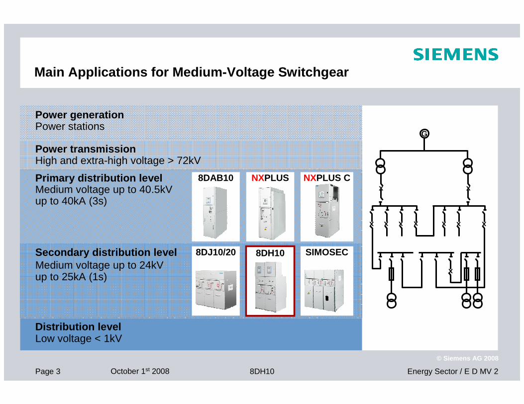
Main Applications for Medium-Voltage Switchgear
Power transmissionHigh and extra-high voltage > 72kV
Primary distribution levelMedium voltage up to 40.5kVup to 40kA (3s)
Secondary distribution levelMedium voltage up to 24kVup to 25kA (1s)
Distribution levelLow voltage < 1kV
8DJ10/20 8DH10 SIMOSEC
8DAB10 NXPLUS NXPLUS C
Power generationPower stations
G
x xx xxx xx x
x
Page 4 October 1st 2008 Energy Sector / E D MV 28DH10
© Siemens AG 2008
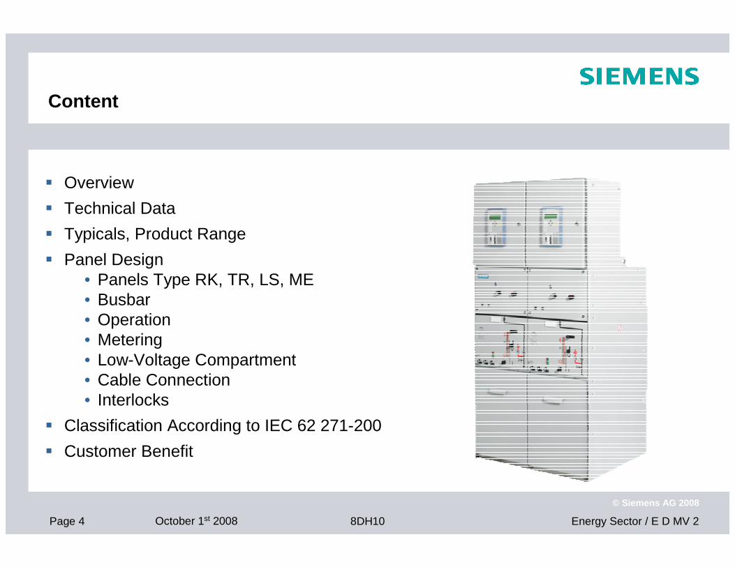
Content
� Overview
� Technical Data
� Typicals, Product Range
� Panel Design• Panels Type RK, TR, LS, ME• Busbar• Operation• Metering• Low-Voltage Compartment• Cable Connection• Interlocks
� Classification According to IEC 62 271-200
� Customer Benefit
Page 5 October 1st 2008 Energy Sector / E D MV 28DH10
© Siemens AG 2008
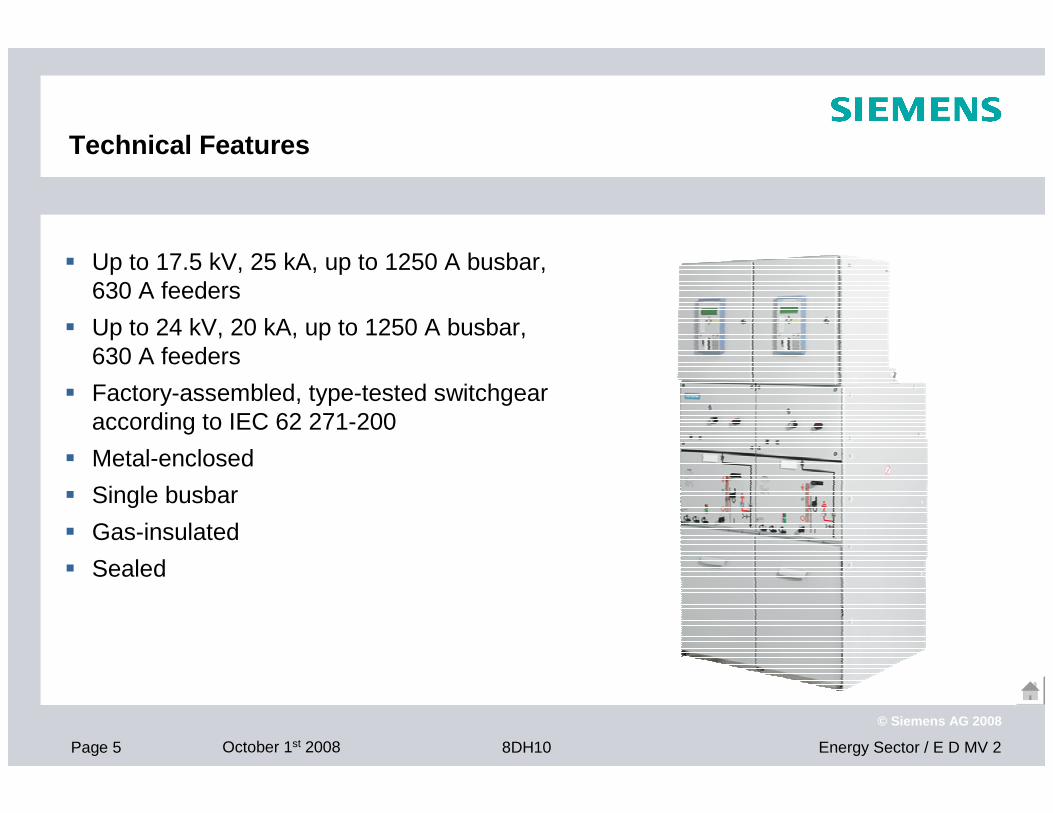
Technical Features
� Up to 17.5 kV, 25 kA, up to 1250 A busbar,630 A feeders
� Up to 24 kV, 20 kA, up to 1250 A busbar,630 A feeders
� Factory-assembled, type-tested switchgear according to IEC 62 271-200
� Metal-enclosed
� Single busbar
� Gas-insulated
� Sealed
Page 6 October 1st 2008 Energy Sector / E D MV 28DH10
© Siemens AG 2008
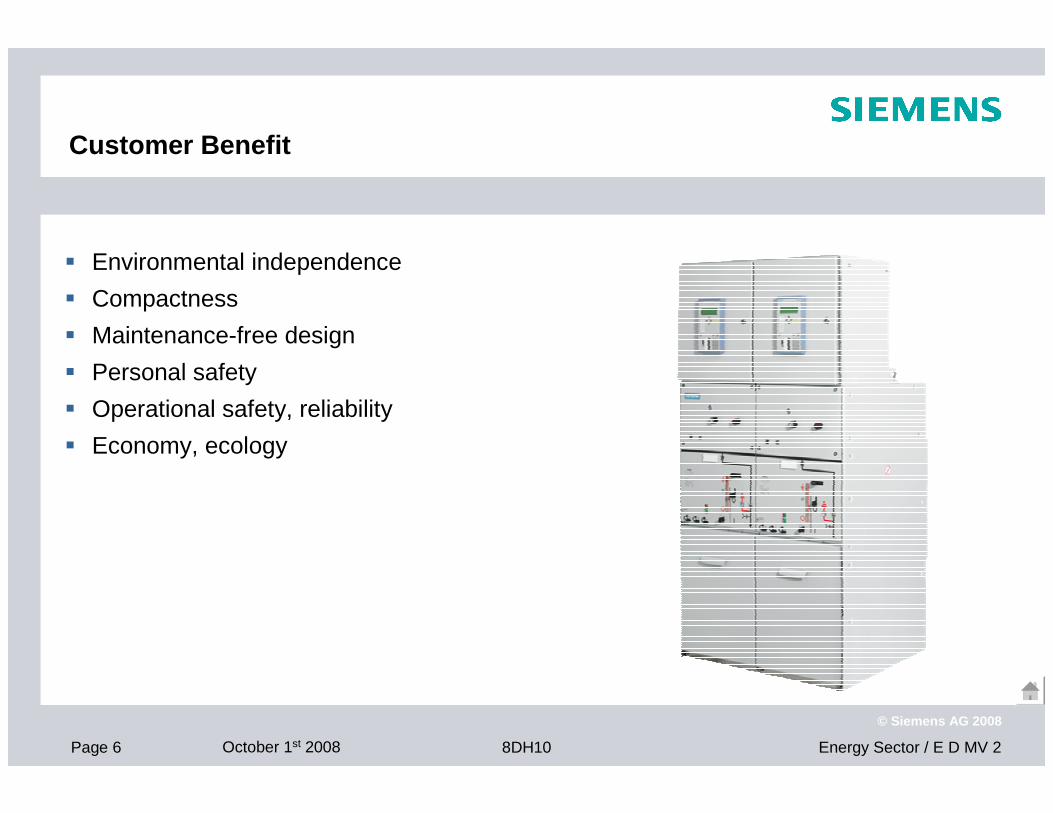
Customer Benefit
� Environmental independence
� Compactness
� Maintenance-free design
� Personal safety
� Operational safety, reliability
� Economy, ecology
Page 7 October 1st 2008 Energy Sector / E D MV 28DH10
© Siemens AG 2008
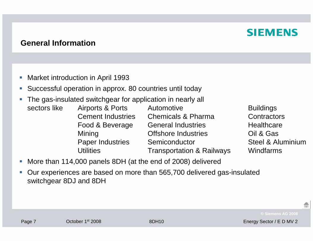
General Information
� Market introduction in April 1993
� Successful operation in approx. 80 countries until today
� The gas-insulated switchgear for application in nearly all sectors like Airports & Ports Automotive Buildings
Cement Industries Chemicals & Pharma ContractorsFood & Beverage General Industries HealthcareMining Offshore Industries Oil & GasPaper Industries Semiconductor Steel & Aluminium Utilities Transportation & Railways Windfarms
� More than 114,000 panels 8DH (at the end of 2008) delivered
� Our experiences are based on more than 565,700 delivered gas-insulated switchgear 8DJ and 8DH
Page 8 October 1st 2008 Energy Sector / E D MV 28DH10
© Siemens AG 2008
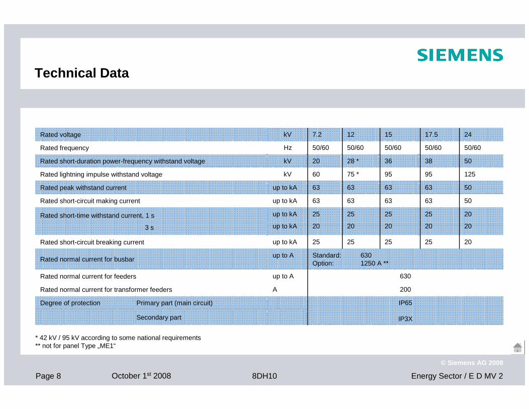
Technical Data
630up to ARated normal current for feeders
20
20
25
20
25
20
25
20
25
20
up to kA
up to kA
Rated short-time withstand current, 1 s
3 s
Standard: 630Option: 1250 A **
up to ARated normal current for busbar
20
50
50
125
50
50/60
24
25
63
63
95
38
50/60
17.5
25
63
63
95
36
50/60
15
25
63
63
75 *
28 *
50/60
12
Secondary part
IP65
IP3X
Degree of protection Primary part (main circuit)
200ARated normal current for transformer feeders
25up to kARated short-circuit breaking current
63up to kARated short-circuit making current
63up to kARated peak withstand current
60kVRated lightning impulse withstand voltage
20kVRated short-duration power-frequency withstand voltage
50/60HzRated frequency
7.2kVRated voltage
* 42 kV / 95 kV according to some national requirements** not for panel Type „ME1“
Page 9 October 1st 2008 Energy Sector / E D MV 28DH10
© Siemens AG 2008
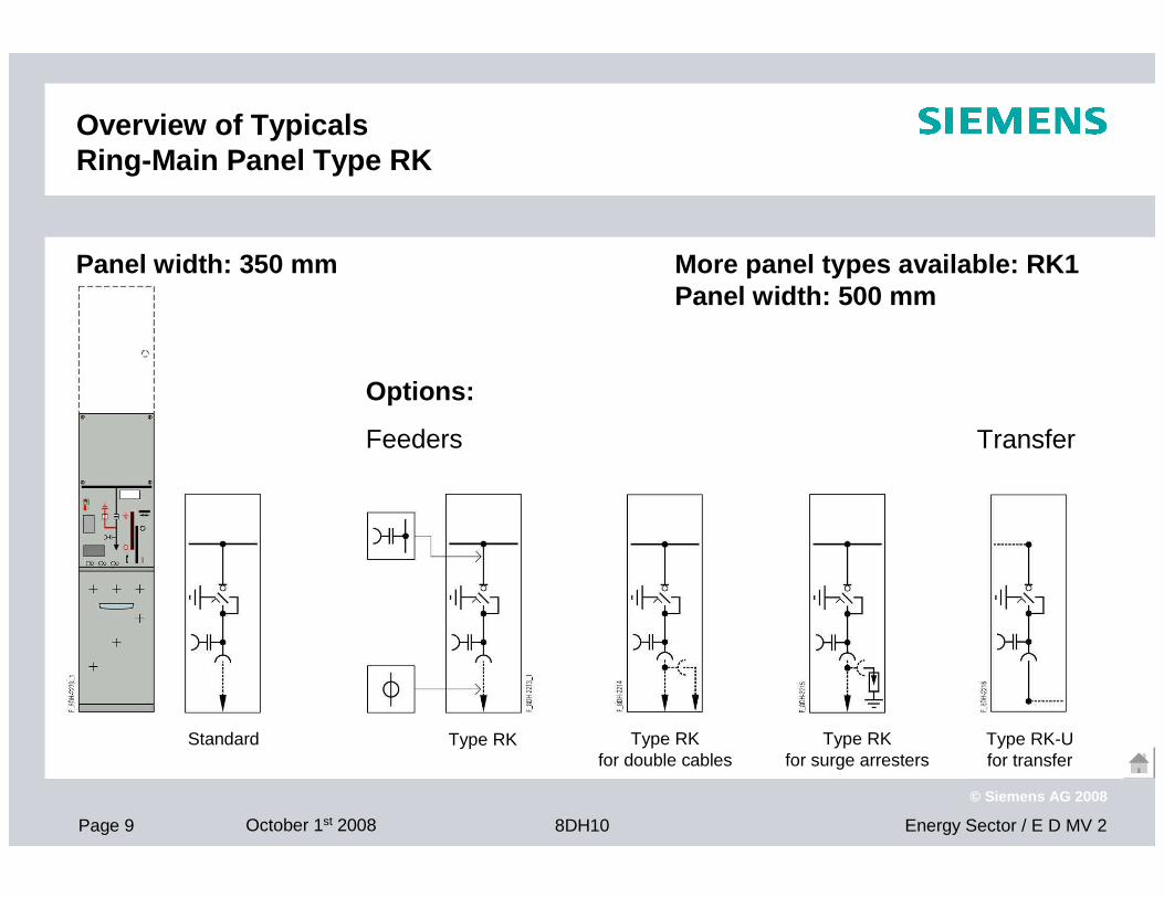
Overview of TypicalsRing-Main Panel Type RK
Type RK
Transfer
Options:
Feeders
Panel width: 350 mm
Standard Type RKfor double cables
Type RKfor surge arresters
Type RK-Ufor transfer
More panel types available: RK1Panel width: 500 mm
Page 10 October 1st 2008 Energy Sector / E D MV 28DH10
© Siemens AG 2008
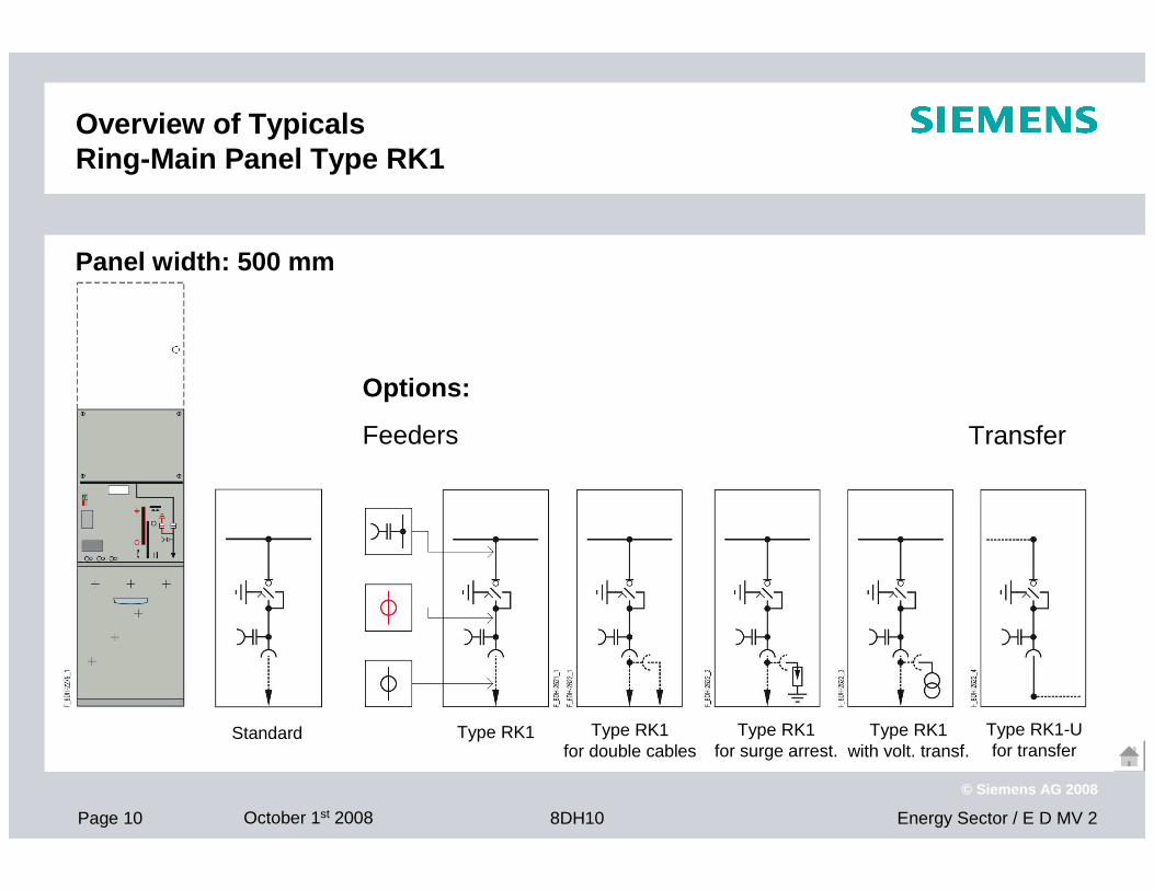
Overview of TypicalsRing-Main Panel Type RK1
Panel width: 500 mm
Options:
Feeders
Standard Type RK1 Type RK1for double cables
Type RK1for surge arrest.
Type RK1with volt. transf.
Type RK1-Ufor transfer
Transfer
Page 11 October 1st 2008 Energy Sector / E D MV 28DH10
© Siemens AG 2008
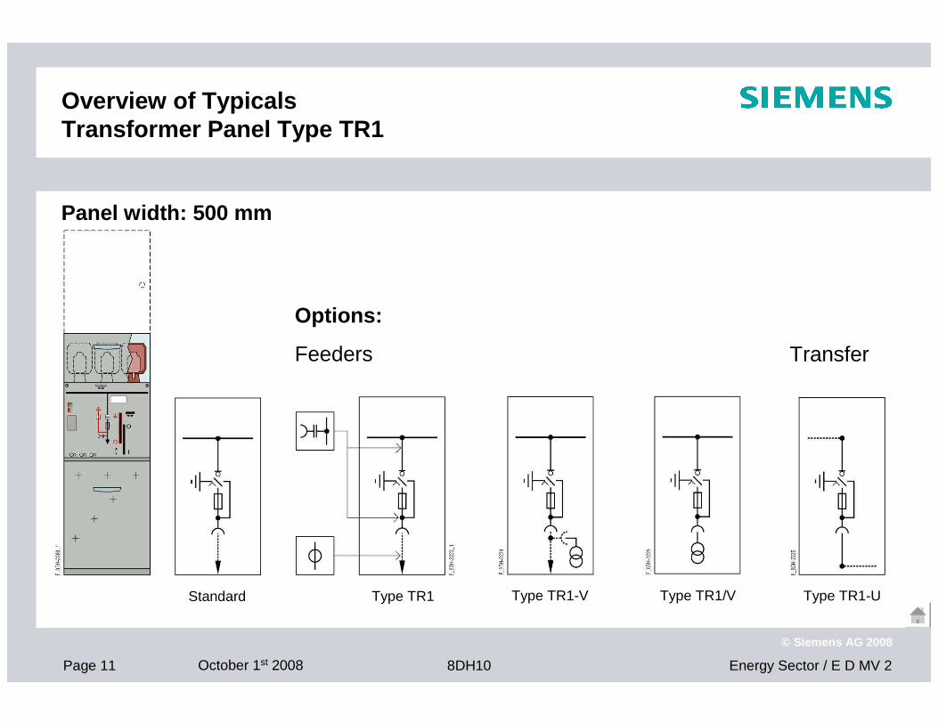
Overview of TypicalsTransformer Panel Type TR1
Type TR1 Type TR1-V Type TR1/V Type TR1-U
Transfer
Options:
Feeders
Panel width: 500 mm
Standard
Page 12 October 1st 2008 Energy Sector / E D MV 28DH10
© Siemens AG 2008
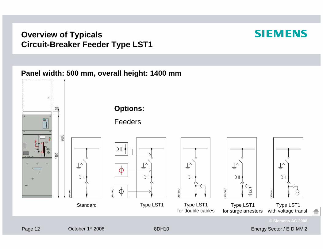
Overview of TypicalsCircuit-Breaker Feeder Type LST1
Panel width: 500 mm, overall height: 1400 mm
Options:
Feeders
Type LST1 Type LST1for double cables
Type LST1for surge arresters
Type LST1with voltage transf.
Standard
Page 13 October 1st 2008 Energy Sector / E D MV 28DH10
© Siemens AG 2008
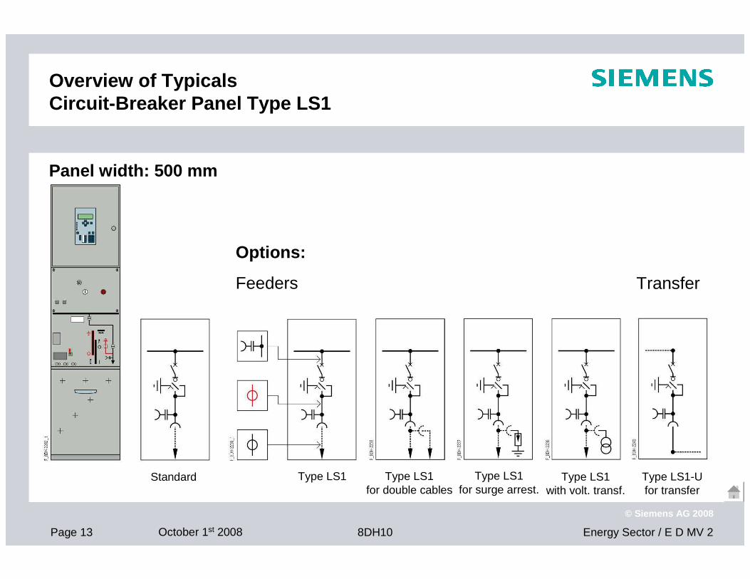
Overview of TypicalsCircuit-Breaker Panel Type LS1
Type LS1
Transfer
Options:
Feeders
Panel width: 500 mm
Standard Type LS1for double cables
Type LS1for surge arrest.
Type LS1with volt. transf.
Type LS1-Ufor transfer
Page 14 October 1st 2008 Energy Sector / E D MV 28DH10
© Siemens AG 2008
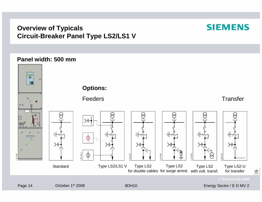
Overview of TypicalsCircuit-Breaker Panel Type LS2/LS1 V
Type LS2/LS1 V
Transfer
Options:
Feeders
Panel width: 500 mm
Standard Type LS2for double cables
Type LS2for surge arrest.
Type LS2with volt. transf.
Type LS2-Ufor transfer
Page 15 October 1st 2008 Energy Sector / E D MV 28DH10
© Siemens AG 2008
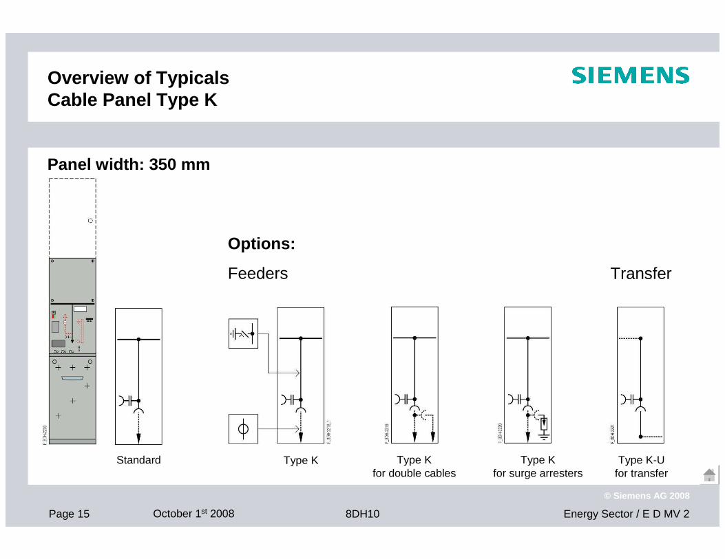
Overview of TypicalsCable Panel Type K
Standard Type K
Transfer
Options:
Feeders
Panel width: 350 mm
Type Kfor double cables
Type Kfor surge arresters
Type K-Ufor transfer
Page 16 October 1st 2008 Energy Sector / E D MV 28DH10
© Siemens AG 2008
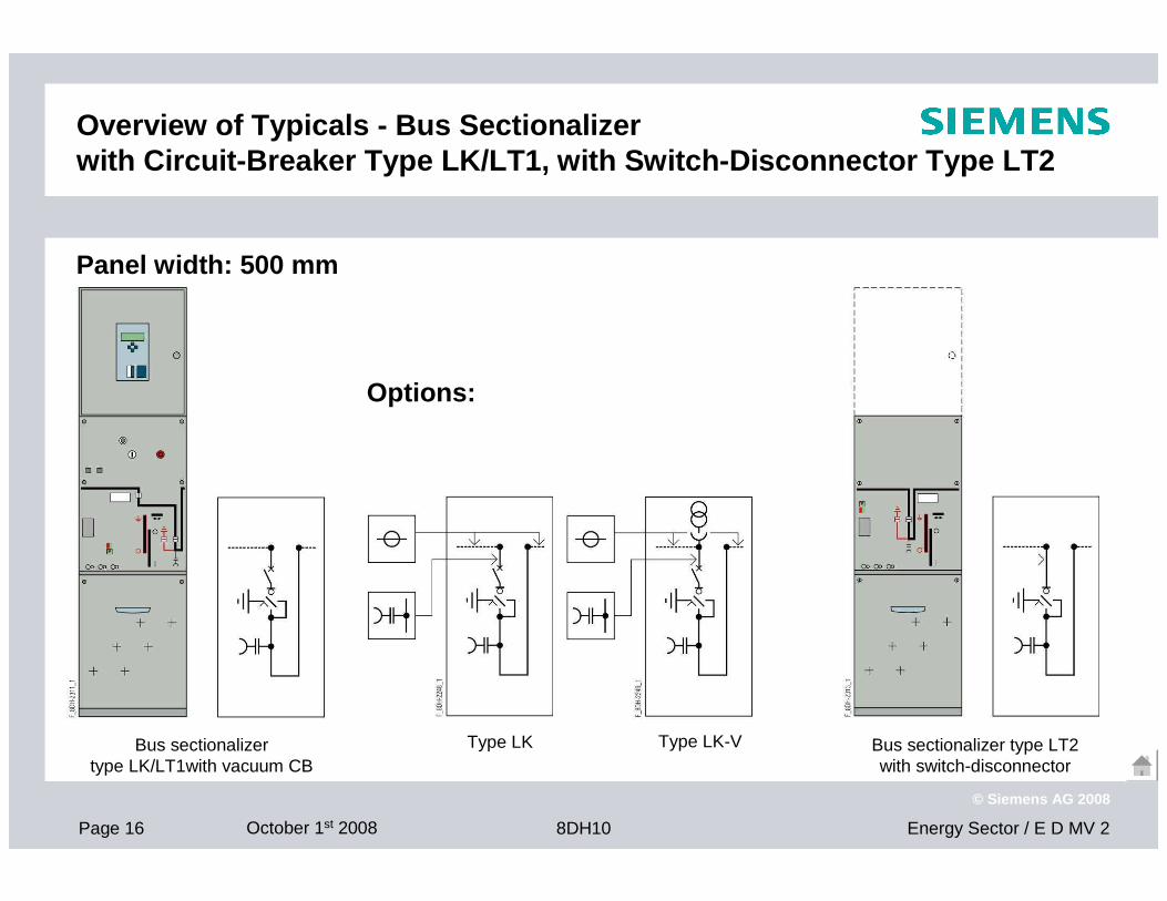
Overview of Typicals - Bus Sectionalizerwith Circuit-Breaker Type LK/LT1, with Switch-Disco nnector Type LT2
Type LK-VType LK Bus sectionalizer type LT2with switch-disconnector
Bus sectionalizertype LK/LT1with vacuum CB
Options:
Panel width: 500 mm
Page 17 October 1st 2008 Energy Sector / E D MV 28DH10
© Siemens AG 2008
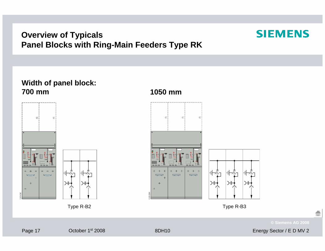
Overview of TypicalsPanel Blocks with Ring-Main Feeders Type RK
Type R-B2 Type R-B3
Width of panel block:700 mm 1050 mm
Page 18 October 1st 2008 Energy Sector / E D MV 28DH10
© Siemens AG 2008
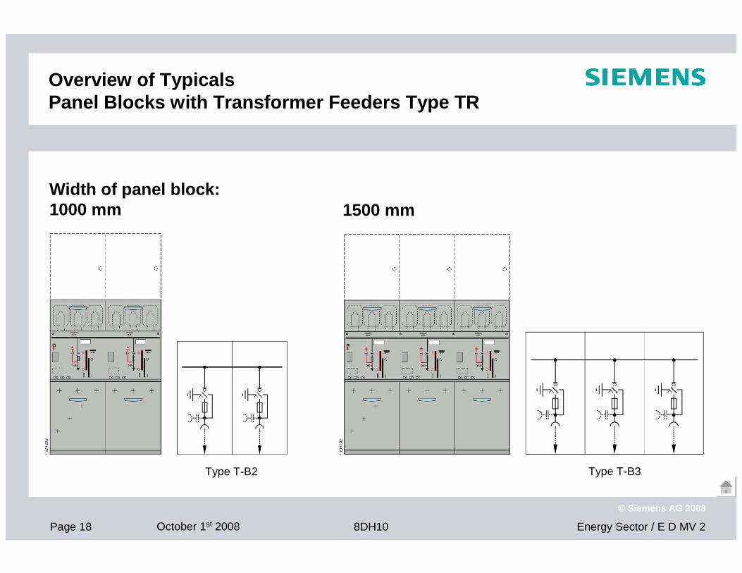
Overview of TypicalsPanel Blocks with Transformer Feeders Type TR
1500 mm
Type T-B2 Type T-B3
Width of panel block:1000 mm
Page 19 October 1st 2008 Energy Sector / E D MV 28DH10
© Siemens AG 2008
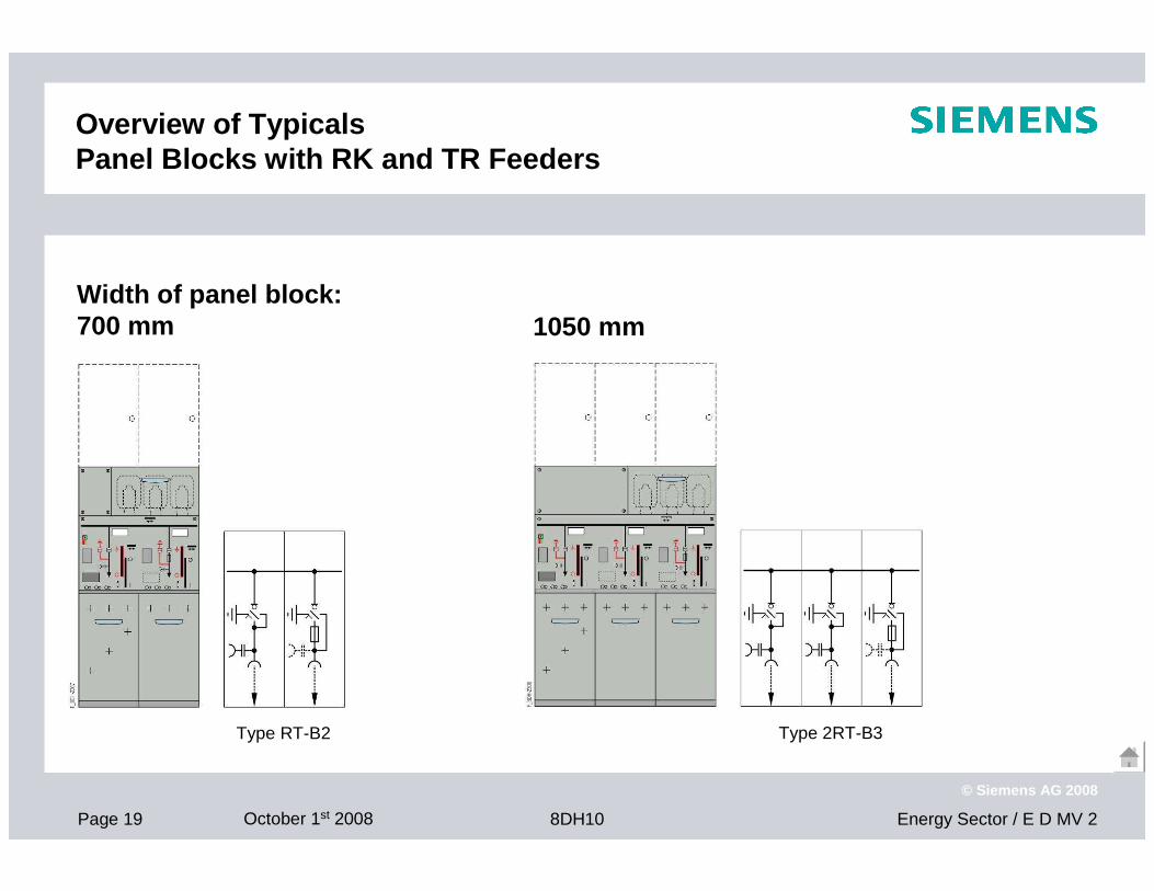
Overview of TypicalsPanel Blocks with RK and TR Feeders
1050 mm
Type RT-B2 Type 2RT-B3
Width of panel block:700 mm

Page 20 October 1st 2008 Energy Sector / E D MV 28DH10
© Siemens AG 2008
Overview of TypicalsPanel Blocks with K, RK and TR Feeders
1400 mm
Type KT-B2 Type 3RT-B4
Width of panel block:700 mm
Page 21 October 1st 2008 Energy Sector / E D MV 28DH10
© Siemens AG 2008
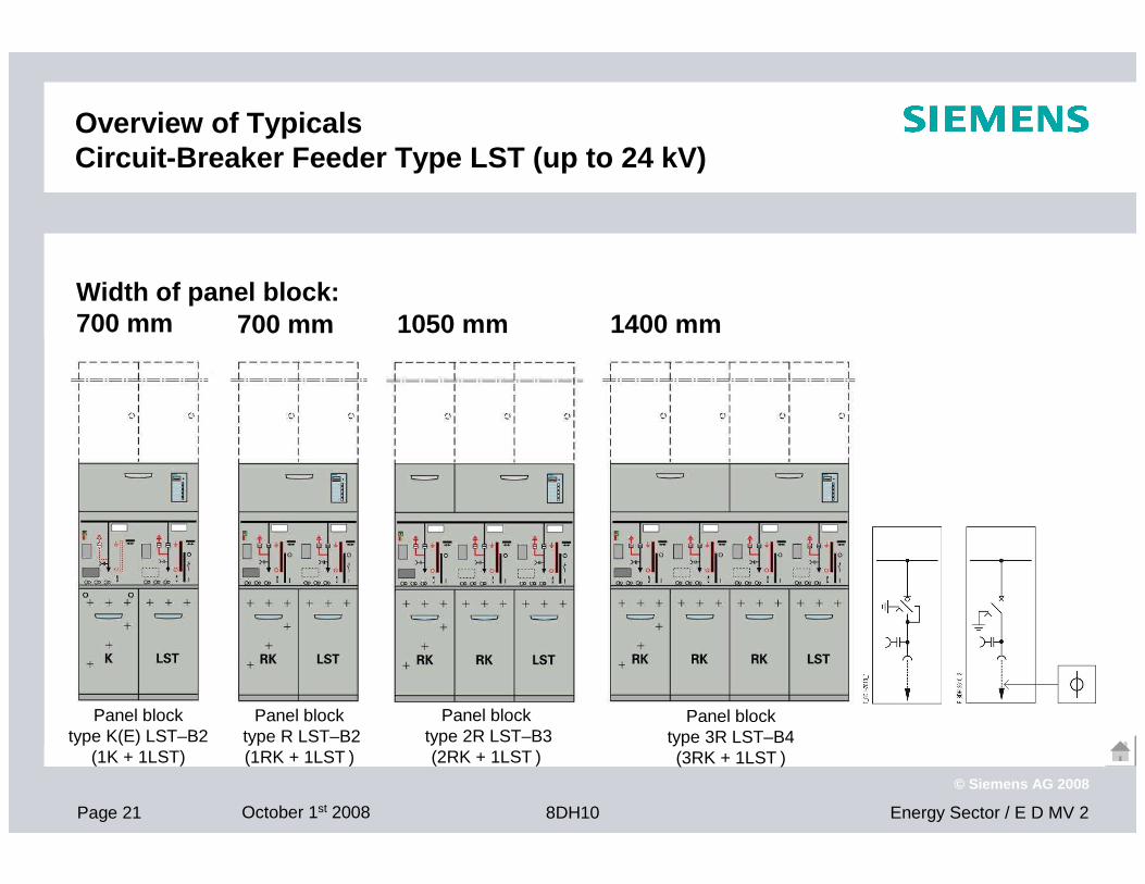
Panel blocktype R LST–B2(1RK + 1LST )
Panel blocktype K(E) LST–B2
(1K + 1LST)
Overview of TypicalsCircuit-Breaker Feeder Type LST (up to 24 kV)
Panel blocktype 2R LST–B3(2RK + 1LST )
Panel block type 3R LST–B4(3RK + 1LST )
1400 mm 1050 mm Width of panel block:700 mm 700 mm
Page 22 October 1st 2008 Energy Sector / E D MV 28DH10
© Siemens AG 2008
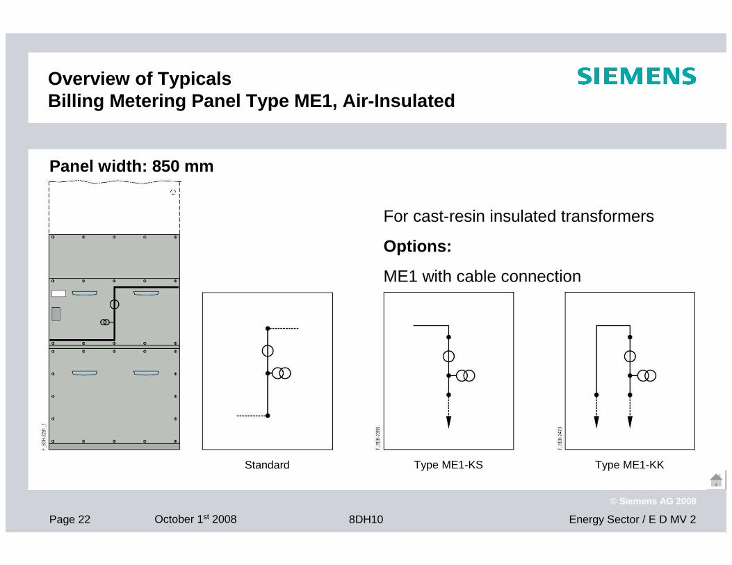
Overview of TypicalsBilling Metering Panel Type ME1, Air-Insulated
Standard Type ME1-KS Type ME1-KK
For cast-resin insulated transformers
Options:
ME1 with cable connection
Panel width: 850 mm
Page 23 October 1st 2008 Energy Sector / E D MV 28DH10
© Siemens AG 2008
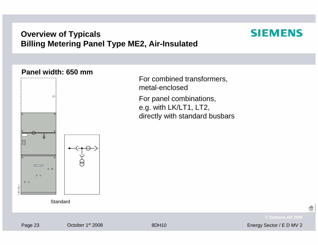
Overview of TypicalsBilling Metering Panel Type ME2, Air-Insulated
Standard
For combined transformers, metal-enclosed
For panel combinations, e.g. with LK/LT1, LT2, directly with standard busbars
Panel width: 650 mm
Page 24 October 1st 2008 Energy Sector / E D MV 28DH10
© Siemens AG 2008
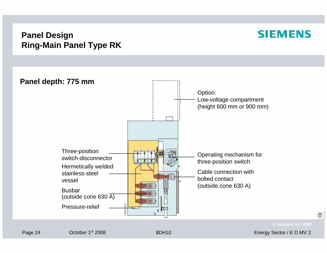
Panel Design Ring-Main Panel Type RK
Hermetically weldedstainless-steel vessel
Busbar(outside cone 630 A)
Pressure-relief
Three-position switch-disconnector
Option: Low-voltage compartment(height 600 mm or 900 mm)
Operating mechanism for three-position switch
Cable connection with bolted contact (outside cone 630 A)
Panel depth: 775 mm
Page 25 October 1st 2008 Energy Sector / E D MV 28DH10
© Siemens AG 2008
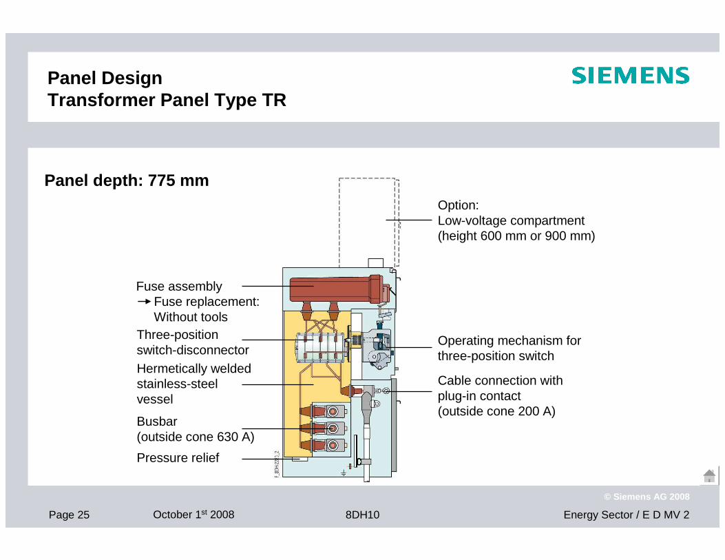
Panel Design Transformer Panel Type TR
Fuse assemblyFuse replacement:Without tools
Option: Low-voltage compartment(height 600 mm or 900 mm)
Operating mechanism for three-position switch
Busbar(outside cone 630 A)
Pressure relief
Hermetically weldedstainless-steel vessel
Three-position switch-disconnector
Cable connection with plug-in contact (outside cone 200 A)
Panel depth: 775 mm
Page 26 October 1st 2008 Energy Sector / E D MV 28DH10
© Siemens AG 2008
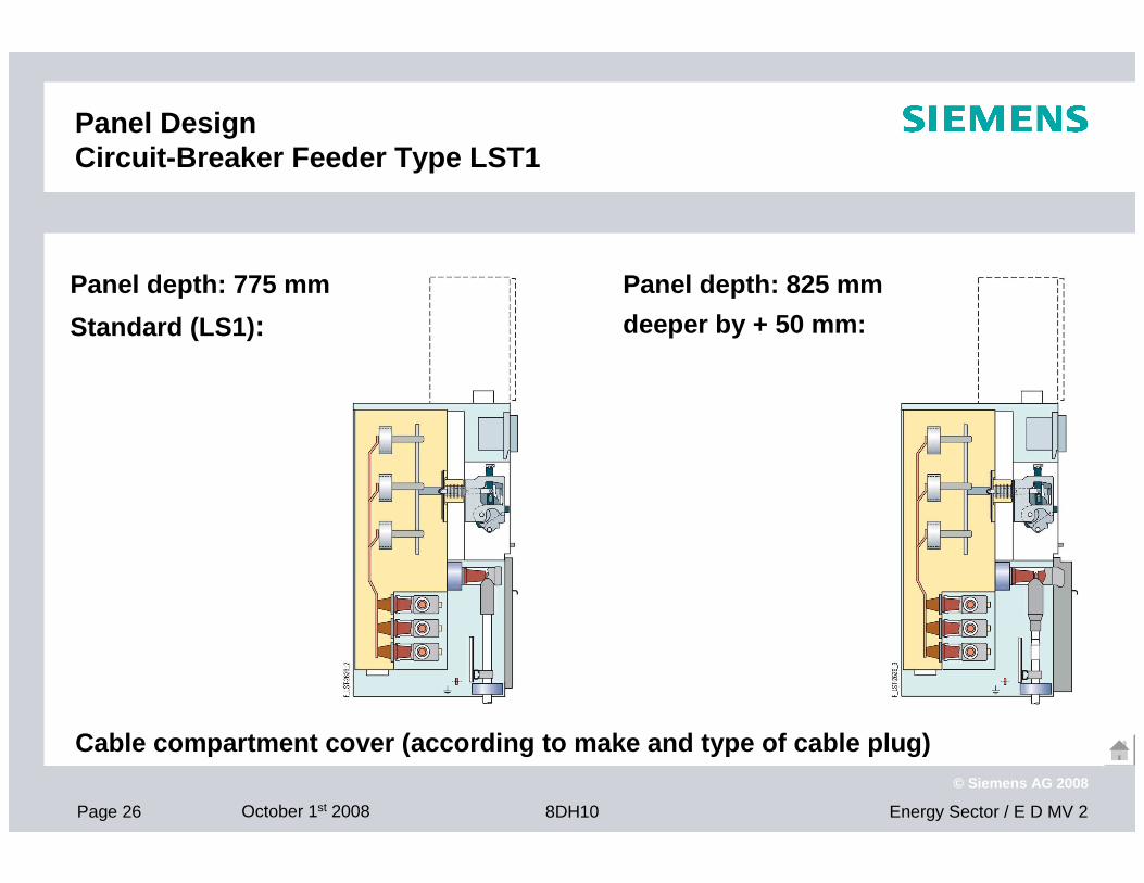
Panel DesignCircuit-Breaker Feeder Type LST1
Panel depth: 825 mm
deeper by + 50 mm:
Cable compartment cover (according to make and type of cable plug)
Panel depth: 775 mm
Standard (LS1) :
Page 27 October 1st 2008 Energy Sector / E D MV 28DH10
© Siemens AG 2008
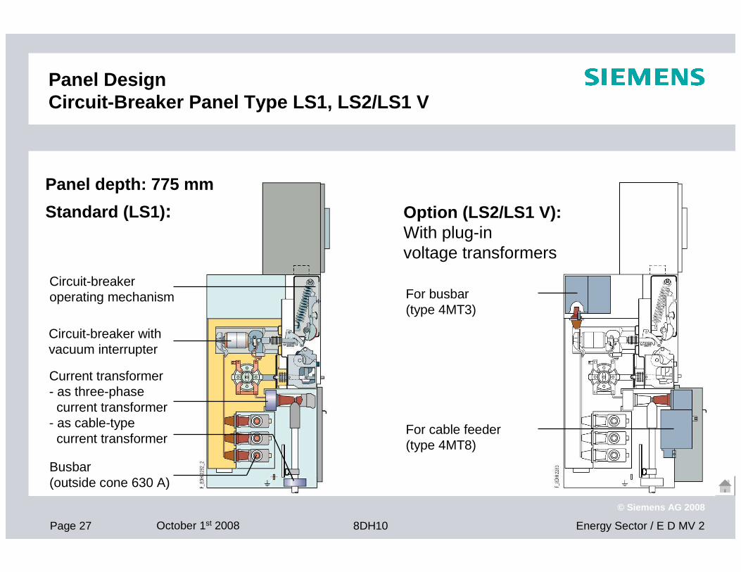
Panel Design Circuit-Breaker Panel Type LS1, LS2/LS1 V
Circuit-breaker operating mechanism
Current transformer- as three-phasecurrent transformer
- as cable-type current transformer
Option (LS2/LS1 V):With plug-in voltage transformers
For busbar(type 4MT3)
For cable feeder(type 4MT8)
Busbar(outside cone 630 A)
Circuit-breaker with vacuum interrupter
Panel depth: 775 mm
Standard (LS1) :
Page 28 October 1st 2008 Energy Sector / E D MV 28DH10
© Siemens AG 2008
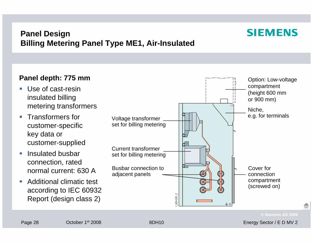
Panel Design Billing Metering Panel Type ME1, Air-Insulated
Voltage transformer set for billing metering
Niche, e.g. for terminals
Busbar connection to adjacent panels
Option: Low-voltage compartment (height 600 mm or 900 mm)
Current transformer set for billing metering
Cover for connection compartment(screwed on)
Panel depth: 775 mm
� Use of cast-resin insulated billing metering transformers
� Transformers for customer-specific key data or customer-supplied
� Insulated busbar connection, rated normal current: 630 A
� Additional climatic test according to IEC 60932 Report (design class 2)
Page 29 October 1st 2008 Energy Sector / E D MV 28DH10
© Siemens AG 2008
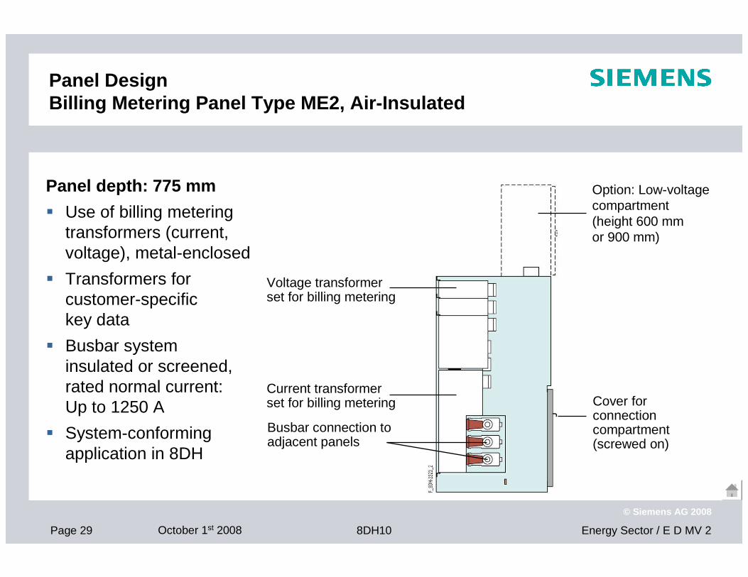
Panel Design Billing Metering Panel Type ME2, Air-Insulated
Panel depth: 775 mm
� Use of billing metering transformers (current, voltage), metal-enclosed
� Transformers for customer-specific key data
� Busbar system insulated or screened,rated normal current: Up to 1250 A
� System-conforming application in 8DH
Voltage transformer set for billing metering
Busbar connection to adjacent panels
Current transformer set for billing metering Cover for
connection compartment(screwed on)
Option: Low-voltage compartment (height 600 mm or 900 mm)
Page 30 October 1st 2008 Energy Sector / E D MV 28DH10
© Siemens AG 2008
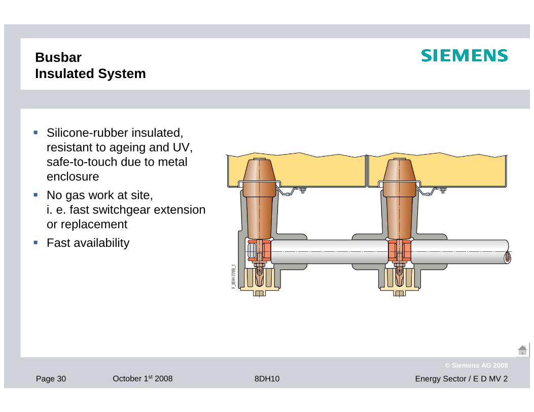
Busbar Insulated System
� Silicone-rubber insulated, resistant to ageing and UV,safe-to-touch due to metal enclosure
� No gas work at site,i. e. fast switchgear extension or replacement
� Fast availability
Page 31 October 1st 2008 Energy Sector / E D MV 28DH10
© Siemens AG 2008
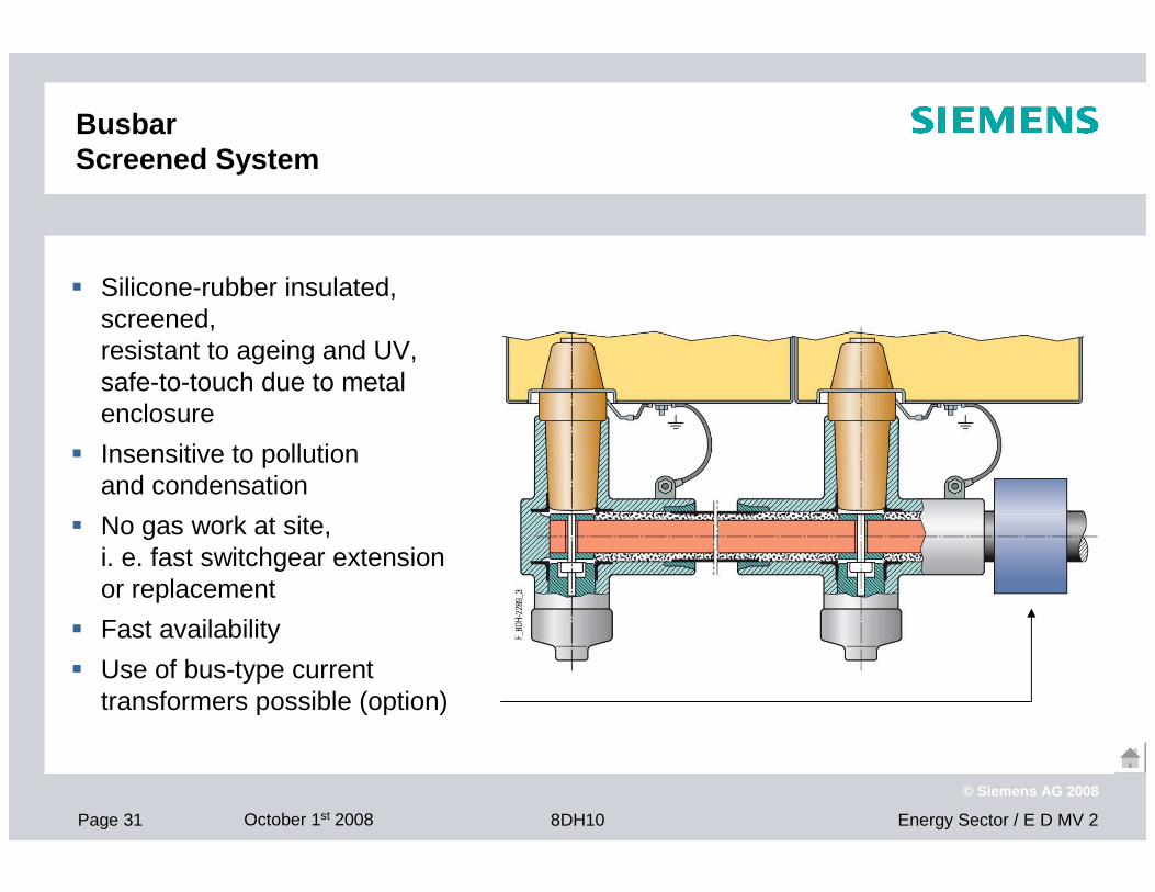
Busbar Screened System
� Silicone-rubber insulated, screened,resistant to ageing and UV,safe-to-touch due to metal enclosure
� Insensitive to pollution and condensation
� No gas work at site,i. e. fast switchgear extension or replacement
� Fast availability
� Use of bus-type current transformers possible (option)
Page 32 October 1st 2008 Energy Sector / E D MV 28DH10
© Siemens AG 2008
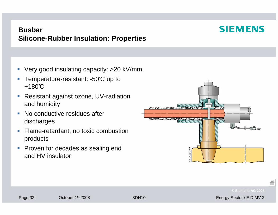
BusbarSilicone-Rubber Insulation: Properties
� Very good insulating capacity: >20 kV/mm
� Temperature-resistant: -50°C up to +180°C
� Resistant against ozone, UV-radiation and humidity
� No conductive residues after discharges
� Flame-retardant, no toxic combustion products
� Proven for decades as sealing end and HV insulator
Page 33 October 1st 2008 Energy Sector / E D MV 28DH10
© Siemens AG 2008
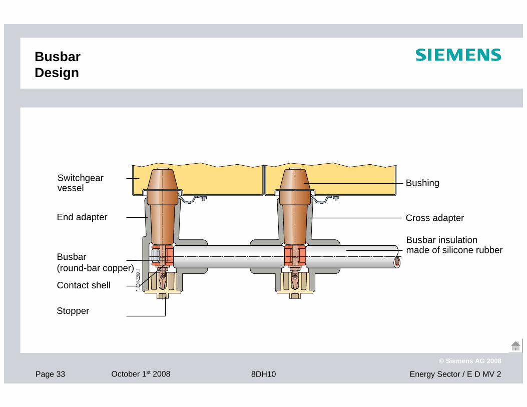
BusbarDesign
Busbar insulationmade of silicone rubber
Cross adapter
Bushing
Stopper
Contact shell
Busbar(round-bar copper)
End adapter
Switchgear vessel
Page 34 October 1st 2008 Energy Sector / E D MV 28DH10
© Siemens AG 2008
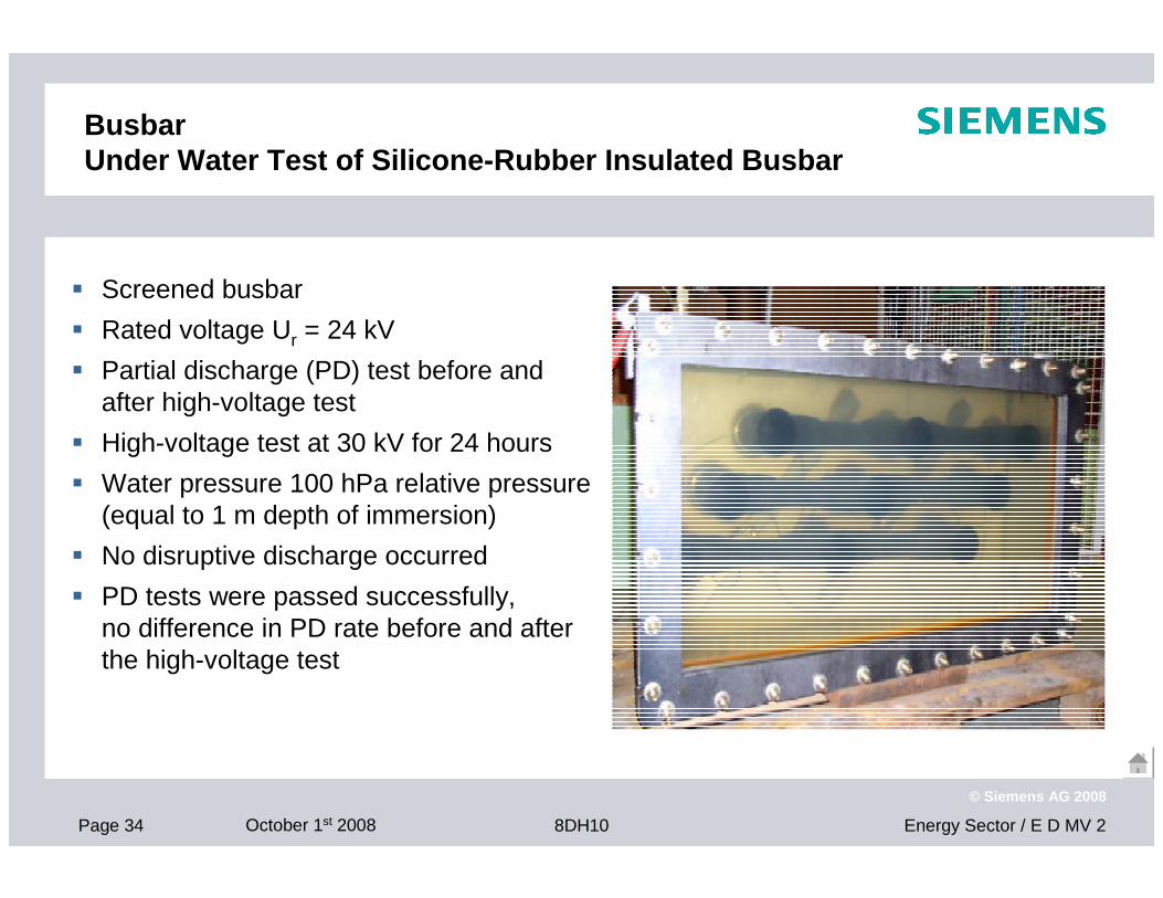
BusbarUnder Water Test of Silicone-Rubber Insulated Busba r
� Screened busbar
� Rated voltage Ur = 24 kV
� Partial discharge (PD) test before and after high-voltage test
� High-voltage test at 30 kV for 24 hours
� Water pressure 100 hPa relative pressure (equal to 1 m depth of immersion)
� No disruptive discharge occurred
� PD tests were passed successfully, no difference in PD rate before and after the high-voltage test
Page 35 October 1st 2008 Energy Sector / E D MV 28DH10
© Siemens AG 2008
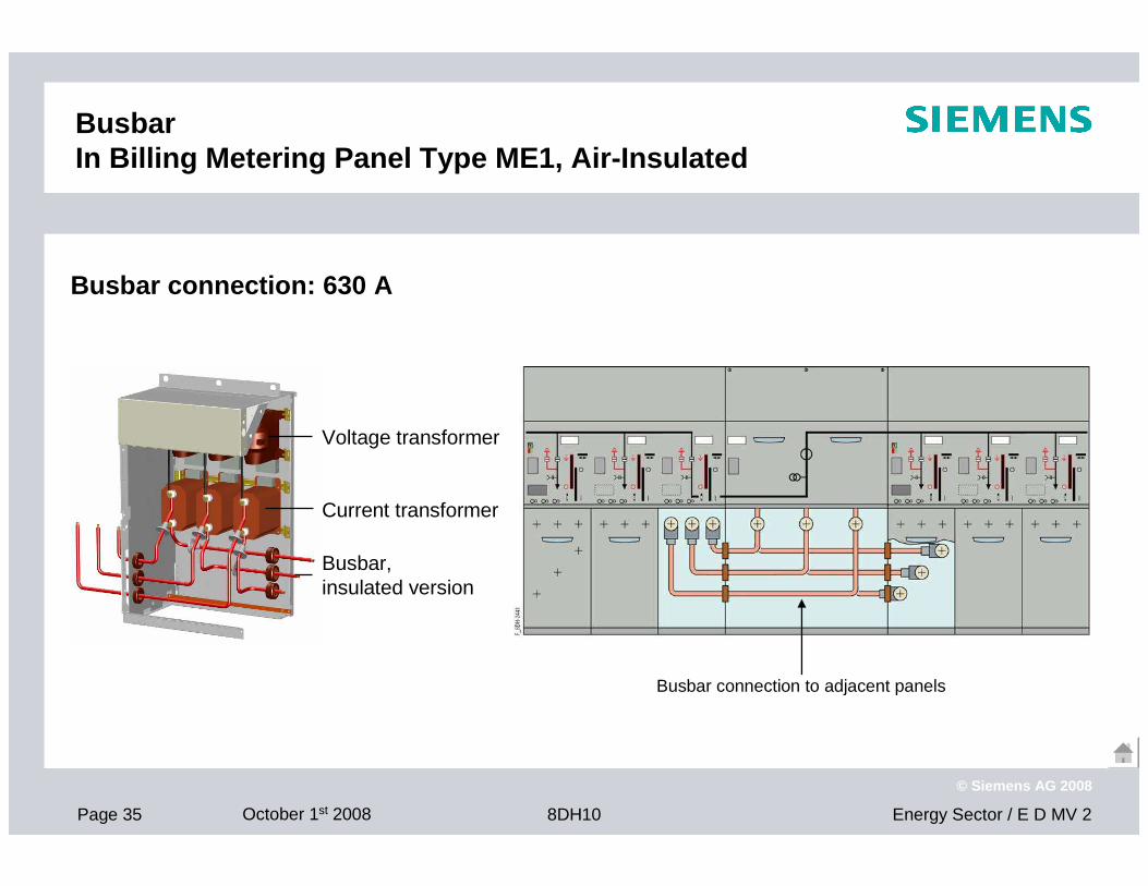
Busbar connection: 630 A
BusbarIn Billing Metering Panel Type ME1, Air-Insulated
Voltage transformer
Current transformer
Busbar, insulated version
Busbar connection to adjacent panels
Page 36 October 1st 2008 Energy Sector / E D MV 28DH10
© Siemens AG 2008
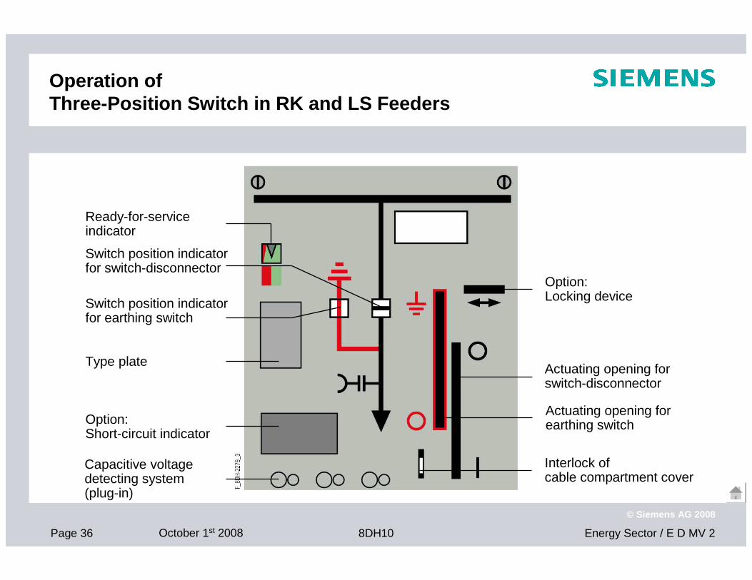
Operation of Three-Position Switch in RK and LS Feeders
Ready-for-service indicator
Actuating opening forearthing switchOption:
Short-circuit indicator
Switch position indicatorfor earthing switch
Switch position indicatorfor switch-disconnector
Option:Locking device
Type plate
Interlock of cable compartment cover
Actuating opening forswitch-disconnector
Capacitive voltage detecting system (plug-in)
Page 37 October 1st 2008 Energy Sector / E D MV 28DH10
© Siemens AG 2008
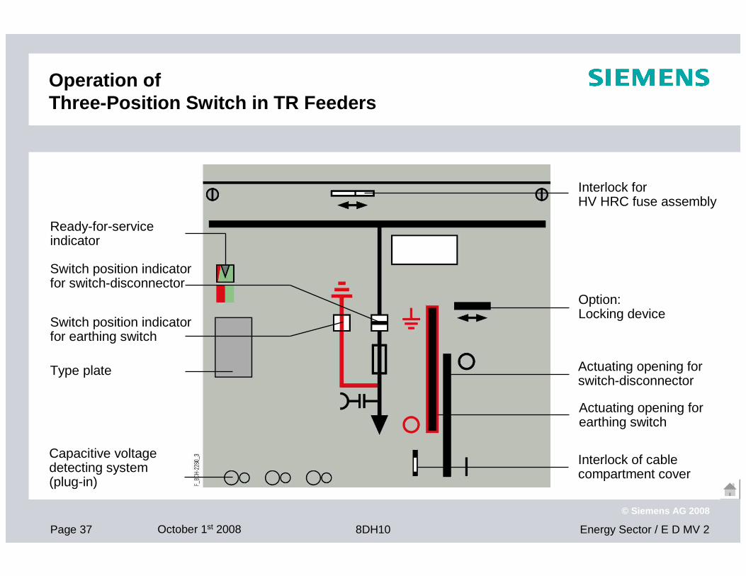
Operation of Three-Position Switch in TR Feeders
Ready-for-service indicator
Actuating opening forearthing switch
Switch position indicatorfor earthing switch
Switch position indicatorfor switch-disconnector
Option:Locking device
Type plate
Interlock of cable compartment cover
Actuating opening forswitch-disconnector
Capacitive voltage detecting system (plug-in)
Interlock for HV HRC fuse assembly
Page 38 October 1st 2008 Energy Sector / E D MV 28DH10
© Siemens AG 2008
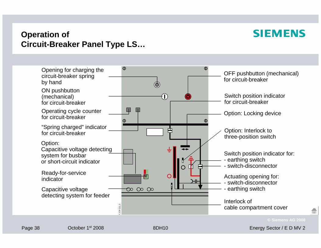
Operation of Circuit-Breaker Panel Type LS…
Ready-for-service indicator
Switch position indicator for circuit-breaker
“Spring charged” indicatorfor circuit-breaker
Opening for charging thecircuit-breaker spring by hand
Operating cycle counter for circuit-breaker
Option: Locking device
Option:Capacitive voltage detectingsystem for busbar or short-circuit indicator
ON pushbutton (mechanical)for circuit-breaker
OFF pushbutton (mechanical)for circuit-breaker
Switch position indicator for:- earthing switch- switch-disconnector
Capacitive voltage detecting system for feeder
Actuating opening for:- switch-disconnector- earthing switch
Interlock of cable compartment cover
Option: Interlock to three-position switch
Page 39 October 1st 2008 Energy Sector / E D MV 28DH10
© Siemens AG 2008
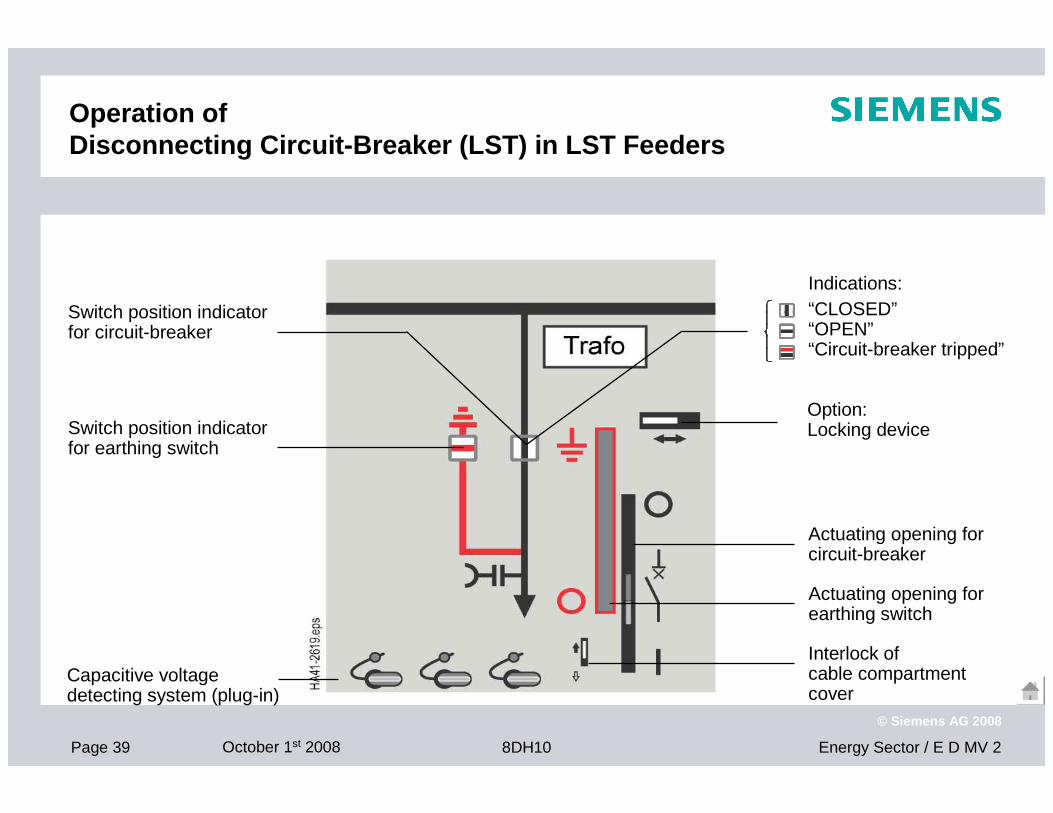
Operation of Disconnecting Circuit-Breaker (LST) in LST Feeders
Capacitive voltage detecting system (plug-in)
Option:Locking device
Actuating opening forcircuit-breaker
Actuating opening forearthing switch
Switch position indicatorfor earthing switch
Switch position indicatorfor circuit-breaker
Interlock of cable compartment cover
Indications:“CLOSED”“OPEN”“Circuit-breaker tripped”
Page 40 October 1st 2008 Energy Sector / E D MV 28DH10
© Siemens AG 2008
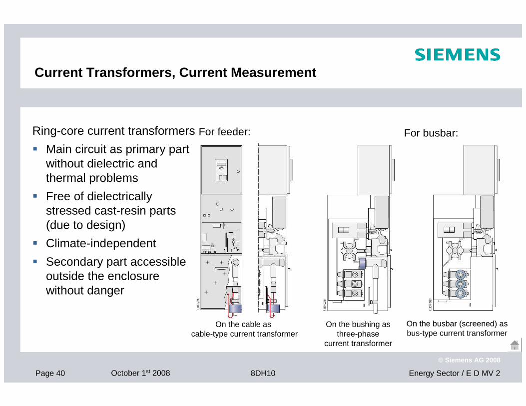
Current Transformers, Current Measurement
Ring-core current transformers
� Main circuit as primary part without dielectric and thermal problems
� Free of dielectrically stressed cast-resin parts (due to design)
� Climate-independent
� Secondary part accessible outside the enclosure without danger
For feeder: For busbar:
On the cable as cable-type current transformer
On the bushing as three-phase
current transformer
On the busbar (screened) as bus-type current transformer
Page 41 October 1st 2008 Energy Sector / E D MV 28DH10
© Siemens AG 2008
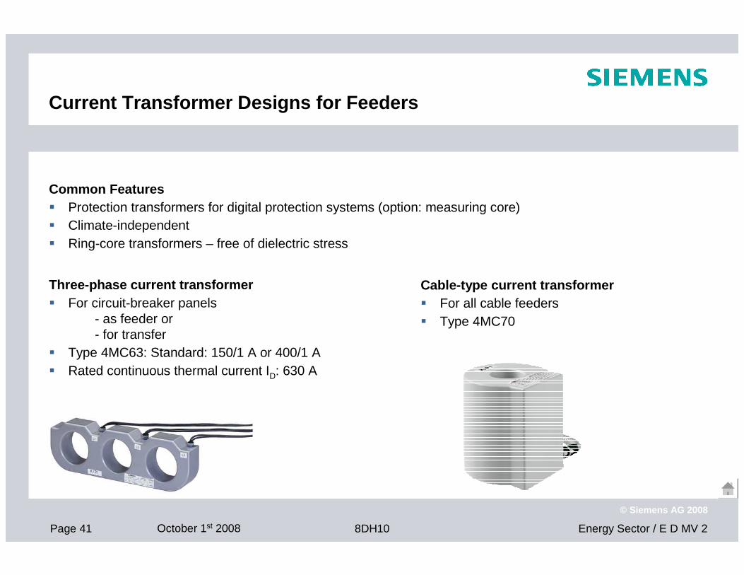
Current Transformer Designs for Feeders
Three-phase current transformer� For circuit-breaker panels
- as feeder or - for transfer
� Type 4MC63: Standard: 150/1 A or 400/1 A� Rated continuous thermal current ID: 630 A
Cable-type current transformer� For all cable feeders� Type 4MC70
Common Features� Protection transformers for digital protection systems (option: measuring core)� Climate-independent� Ring-core transformers – free of dielectric stress
Page 42 October 1st 2008 Energy Sector / E D MV 28DH10
© Siemens AG 2008
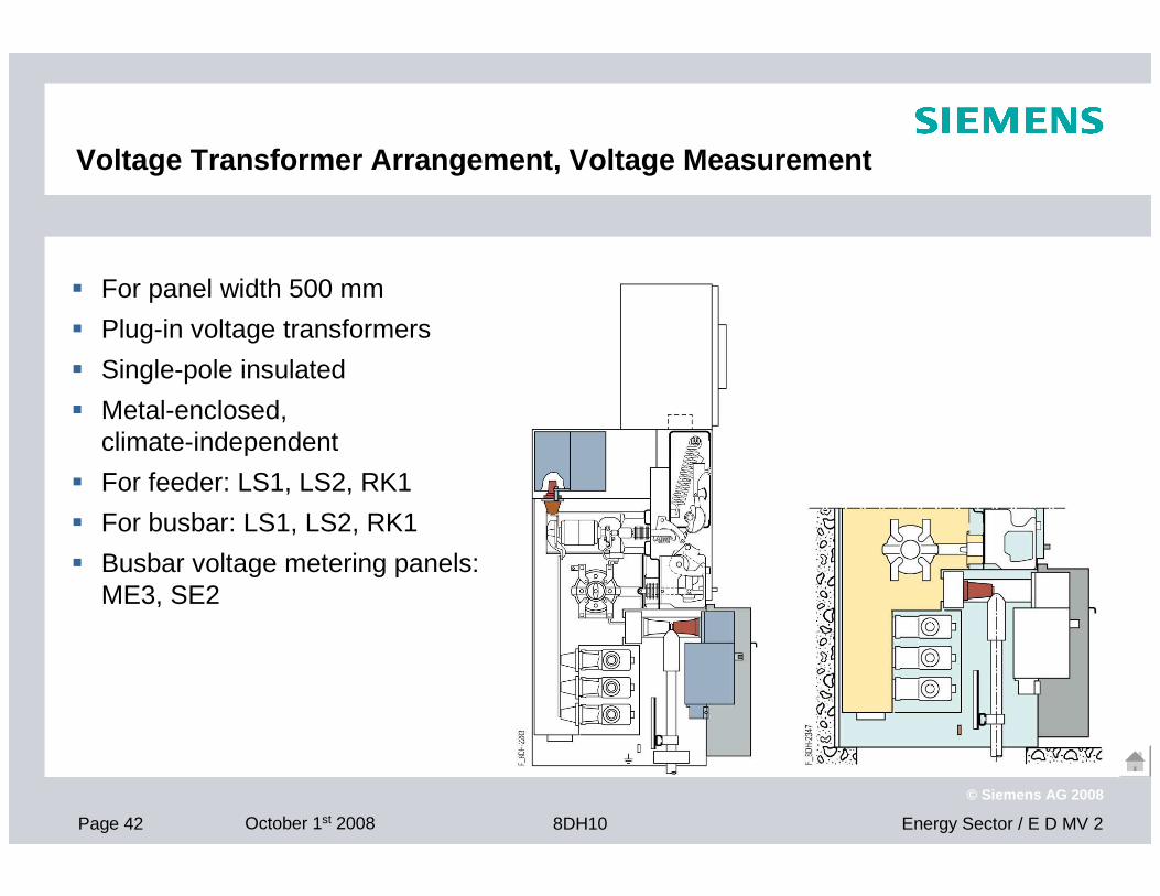
Voltage Transformer Arrangement, Voltage Measuremen t
� For panel width 500 mm
� Plug-in voltage transformers
� Single-pole insulated
� Metal-enclosed, climate-independent
� For feeder: LS1, LS2, RK1
� For busbar: LS1, LS2, RK1
� Busbar voltage metering panels: ME3, SE2
Page 43 October 1st 2008 Energy Sector / E D MV 28DH10
© Siemens AG 2008
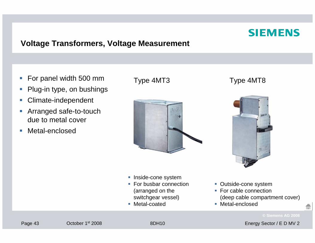
Voltage Transformers, Voltage Measurement
� For panel width 500 mm
� Plug-in type, on bushings
� Climate-independent
� Arranged safe-to-touch due to metal cover
� Metal-enclosed
Type 4MT3 Type 4MT8
� Inside-cone system� For busbar connection
(arranged on the switchgear vessel)
� Metal-coated
� Outside-cone system� For cable connection
(deep cable compartment cover)� Metal-enclosed
Page 44 October 1st 2008 Energy Sector / E D MV 28DH10
© Siemens AG 2008
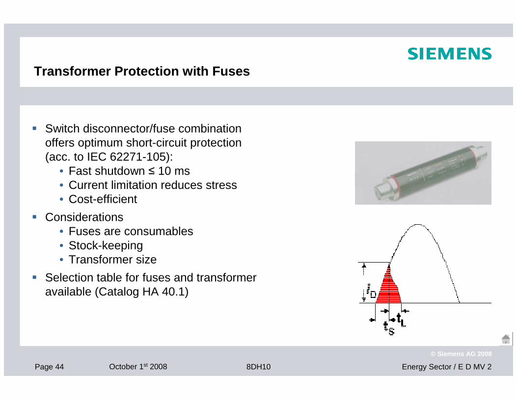
Transformer Protection with Fuses
� Switch disconnector/fuse combination offers optimum short-circuit protection(acc. to IEC 62271-105):
• Fast shutdown ≤ 10 ms• Current limitation reduces stress• Cost-efficient
� Considerations• Fuses are consumables• Stock-keeping• Transformer size
� Selection table for fuses and transformer available (Catalog HA 40.1)
Page 45 October 1st 2008 Energy Sector / E D MV 28DH10
© Siemens AG 2008
Transformer Protection with Circuit-Breaker
Circuit-breaker design:
Circuit-breaker with disconnecting function as three-position switch
(acc. to IEC 62271-100, T100s)
� For transformer ratings ≥ 0.8 MVA / 7.2 kV
≥ 1.25 MVA / 12 kV≥ 1.25 MVA / 13.8 kV
≥ 1.6 MVA / 20 kV
otherwise: HV HRC fuses
� Cost-efficient at high transformer ratings
� Protection relay, with or without auxiliary voltage supply
� Simple standardized solutions, for complete typicals
Page 46 October 1st 2008 Energy Sector / E D MV 28DH10
© Siemens AG 2008
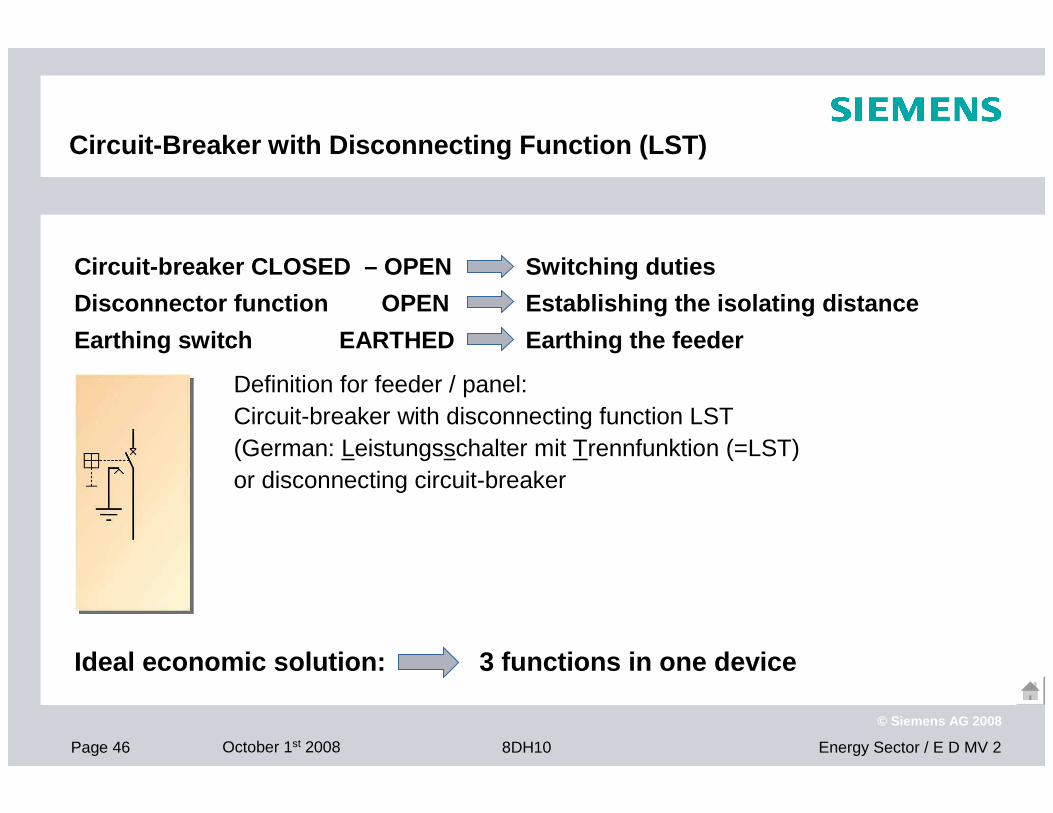
Circuit-Breaker with Disconnecting Function (LST)
Circuit-breaker CLOSED – OPEN Switching duties
Disconnector function OPEN Establishing the i solating distance
Earthing switch EARTHED Earthing the feeder
Definition for feeder / panel: Circuit-breaker with disconnecting function LST(German: Leistungsschalter mit Trennfunktion (=LST)or disconnecting circuit-breaker
Ideal economic solution: 3 functions in one device
Page 47 October 1st 2008 Energy Sector / E D MV 28DH10
© Siemens AG 2008
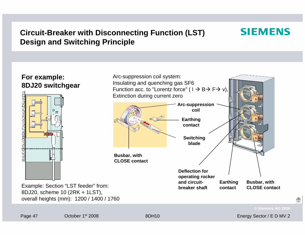
Circuit-Breaker with Disconnecting Function (LST) Design and Switching Principle
For example: 8DJ20 switchgear
Example: Section “LST feeder” from: 8DJ20, scheme 10 (2RK + 1LST),overall heights (mm): 1200 / 1400 / 1760
Busbar, with CLOSE contact
Earthing contact
Deflection for operating rocker and circuit-breaker shaft
Arc-suppression coil system: Insulating and quenching gas SF6Function acc. to "Lorentz force” ( I � B� F� v),Extinction during current zero
Switching blade
Arc-suppression coil
Busbar, with CLOSE contact
Earthing contact
Page 48 October 1st 2008 Energy Sector / E D MV 28DH10
© Siemens AG 2008
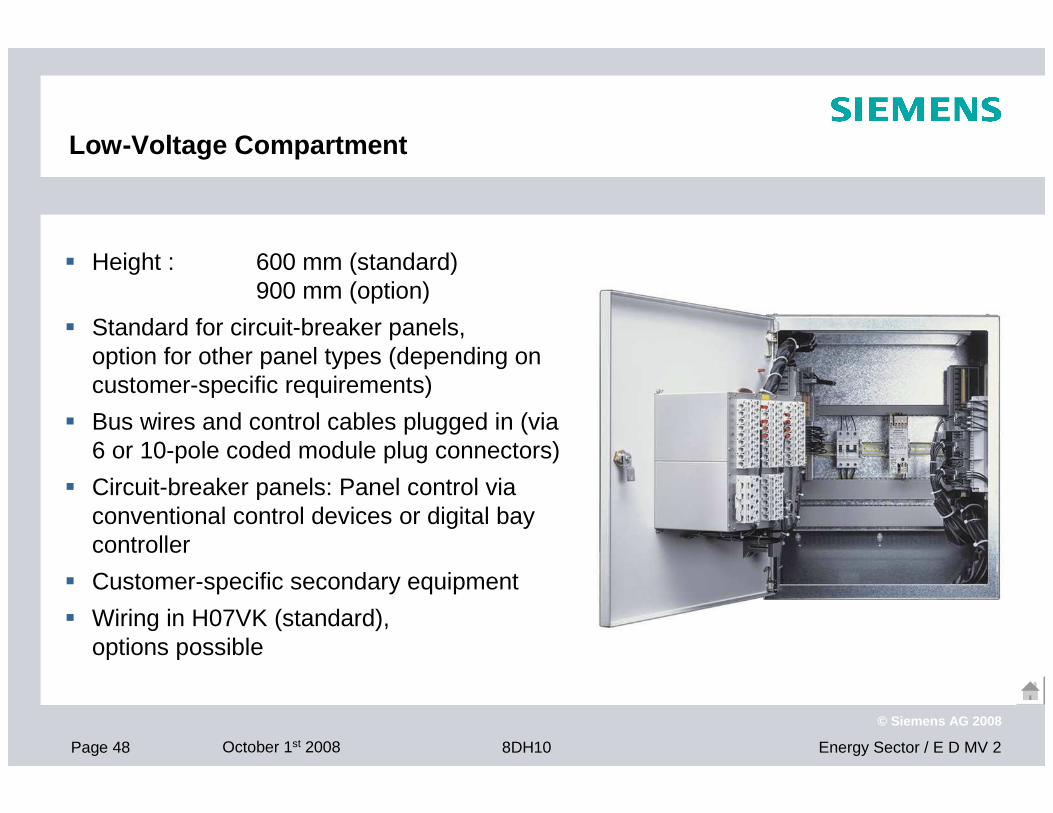
Low-Voltage Compartment
� Height : 600 mm (standard)900 mm (option)
� Standard for circuit-breaker panels, option for other panel types (depending on customer-specific requirements)
� Bus wires and control cables plugged in (via 6 or 10-pole coded module plug connectors)
� Circuit-breaker panels: Panel control via conventional control devices or digital bay controller
� Customer-specific secondary equipment
� Wiring in H07VK (standard), options possible
Page 49 October 1st 2008 Energy Sector / E D MV 28DH10
© Siemens AG 2008
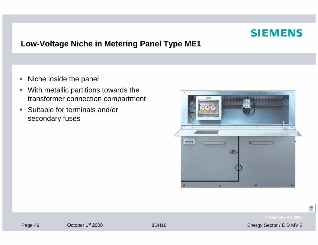
Low-Voltage Niche in Metering Panel Type ME1
� Niche inside the panel
� With metallic partitions towards the transformer connection compartment
� Suitable for terminals and/or secondary fuses
Page 50 October 1st 2008 Energy Sector / E D MV 28DH10
© Siemens AG 2008
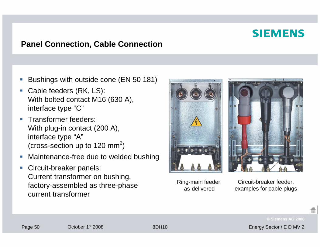
Panel Connection, Cable Connection
� Bushings with outside cone (EN 50 181)
� Cable feeders (RK, LS): With bolted contact M16 (630 A), interface type “C”
� Transformer feeders: With plug-in contact (200 A), interface type “A”(cross-section up to 120 mm2)
� Maintenance-free due to welded bushing
� Circuit-breaker panels:Current transformer on bushing, factory-assembled as three-phase current transformer
Ring-main feeder,as-delivered
Circuit-breaker feeder,examples for cable plugs
Page 51 October 1st 2008 Energy Sector / E D MV 28DH10
© Siemens AG 2008
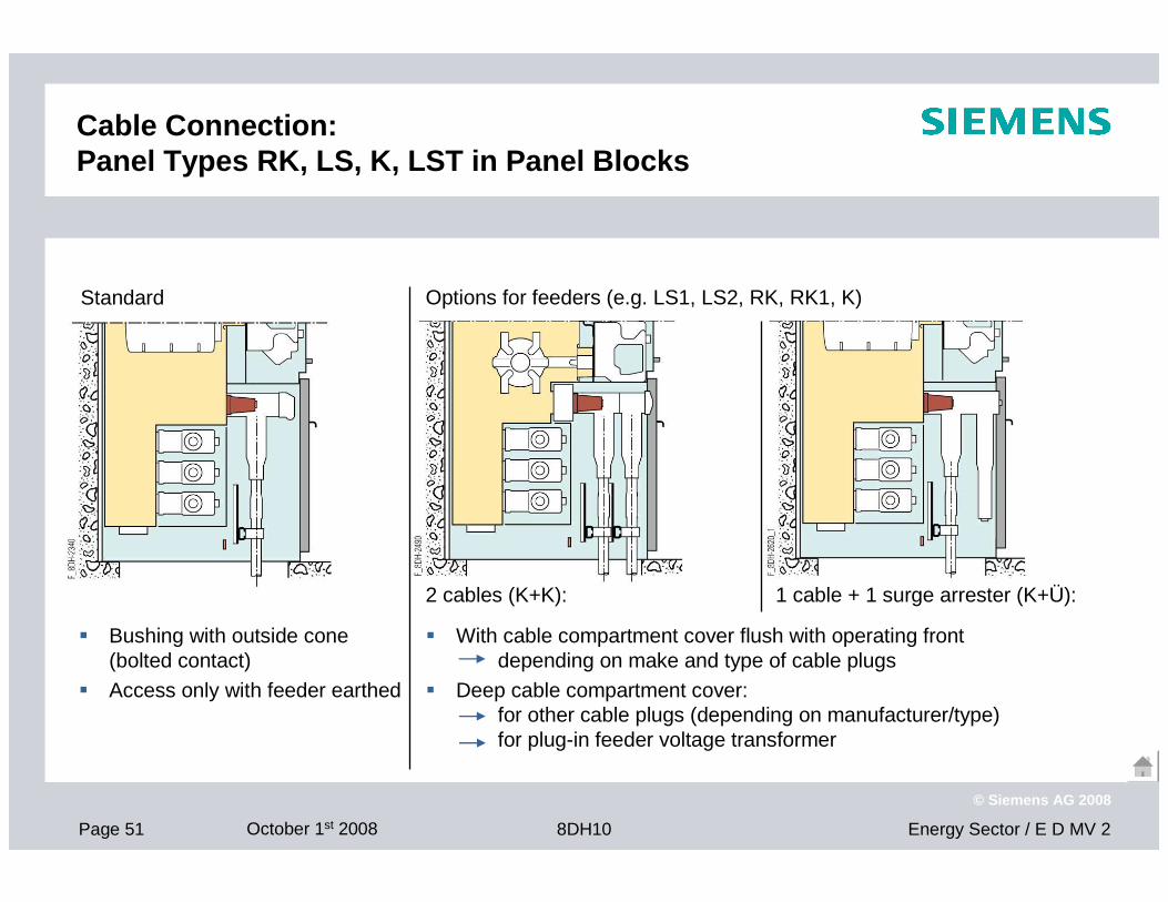
Cable Connection:Panel Types RK, LS, K, LST in Panel Blocks
Options for feeders (e.g. LS1, LS2, RK, RK1, K)
� With cable compartment cover flush with operating front depending on make and type of cable plugs
� Deep cable compartment cover:for other cable plugs (depending on manufacturer/type) for plug-in feeder voltage transformer
2 cables (K+K): 1 cable + 1 surge arrester (K+Ü):
� Bushing with outside cone (bolted contact)
� Access only with feeder earthed
Standard
Page 52 October 1st 2008 Energy Sector / E D MV 28DH10
© Siemens AG 2008
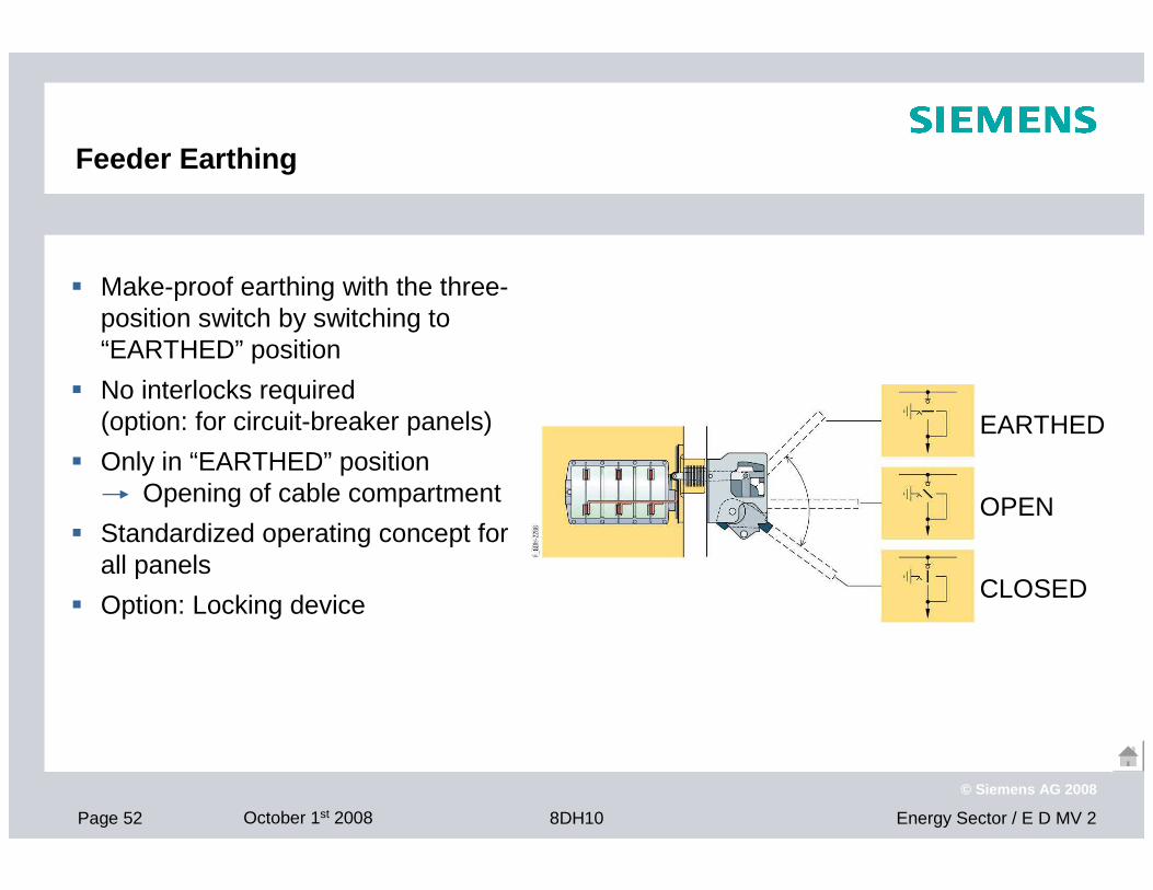
Feeder Earthing
� Make-proof earthing with the three-position switch by switching to “EARTHED” position
� No interlocks required (option: for circuit-breaker panels)
� Only in “EARTHED” position Opening of cable compartment
� Standardized operating concept for all panels
� Option: Locking device
EARTHED
OPEN
CLOSED
Page 53 October 1st 2008 Energy Sector / E D MV 28DH10
© Siemens AG 2008
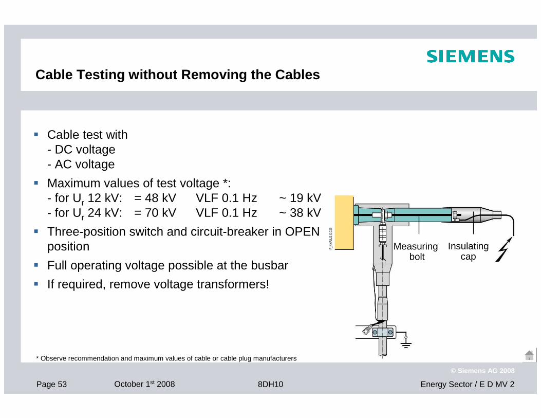
Cable Testing without Removing the Cables
Measuring bolt
Insulating cap
� Cable test with - DC voltage- AC voltage
� Maximum values of test voltage *:- for Ur 12 kV: = 48 kV VLF 0.1 Hz ~ 19 kV- for Ur 24 kV: = 70 kV VLF 0.1 Hz ~ 38 kV
� Three-position switch and circuit-breaker in OPEN position
� Full operating voltage possible at the busbar
� If required, remove voltage transformers!
* Observe recommendation and maximum values of cable or cable plug manufacturers
Page 54 October 1st 2008 Energy Sector / E D MV 28DH10
© Siemens AG 2008
Interlocks (Selection)
Interlocks are designed according to IEC 62 271-200
Standard interlocks
� Three-position switch-disconnector against earthing switch – mechanical� Cable compartment: Only accessible with “feeder earthed”� HV HRC fuse replacement: Only accessible with “feeder earthed” (TR panel)
Additional interlocks (option)
� Circuit-breaker panel: Circuit-breaker against three-position switch-disconnector (mechanical)
� Locking devices for three-position switch� Closing lock-out: Prevents switching the three-position switch-disconnector from
“OPEN” to “CLOSED” when the cable compartment cover is removed� De-earthing lock-out in TR panel: Prevents “de-earthing” the three-position switch-
disconnector (switching from “EARTHED” to “OPEN”) when the cable compartment cover is removed
Page 55 October 1st 2008 Energy Sector / E D MV 28DH10
© Siemens AG 2008
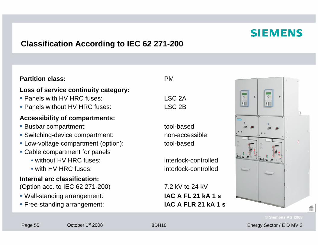
Classification According to IEC 62 271-200
Partition class: PM
Loss of service continuity category:� Panels with HV HRC fuses: LSC 2A� Panels without HV HRC fuses: LSC 2B
Accessibility of compartments:� Busbar compartment: tool-based � Switching-device compartment: non-accessible� Low-voltage compartment (option): tool-based� Cable compartment for panels
• without HV HRC fuses: interlock-controlled• with HV HRC fuses: interlock-controlled
Internal arc classification:(Option acc. to IEC 62 271-200) 7.2 kV to 24 kV
� Wall-standing arrangement: IAC A FL 21 kA 1 s� Free-standing arrangement: IAC A FLR 21 kA 1 s

Page 56 October 1st 2008 Energy Sector / E D MV 28DH10
© Siemens AG 2008
Customer Benefit
� Environmental independence
� Compactness
� Maintenance-free design
� Personal safety
� Operational safety, reliability
� Economy, ecology
Page 57 October 1st 2008 Energy Sector / E D MV 28DH10
© Siemens AG 2008
Environmental Independence
Our solutionWelded without seals,no diffusing humidity
Stainless-steel vessel,long-time corrosion-resistant
Laser-cut, laser-welded materials,exactly fitting quality
Welded stainless-steel metal bellows,for transmission of operating power
System-conforming, shock-proof connection systems
Integral, highly sensitive leakage detection system in the factory,sealed for life
Non-contact and non-sealed transmission of capacitive voltage detecting system
Your benefitInsensitive to aggressive environments (salt water, tropical areas, dust, humidity, chemical pollutants),no oxidation of contacts and bolted joints, no condensation,no pollution layers on insulators, no resinifying grease
Continuous insulation quality
No ingress of foreign bodies, small animals
Independent of site altitudewith the corresponding options
Page 58 October 1st 2008 Energy Sector / E D MV 28DH10
© Siemens AG 2008
Compactness
Our solutionSF6-insulation,compact construction
Panel blocks with up to 4 feeders
Combined disconnector and earthing switch,compact switch design
User-friendly cable connection height
SIPROTEC bay controller: Digital control, interlocking and protection system,compact secondary systems with high functional density
Your benefitMinimum space requirements, building volume saved: Up to 38 % at 12 kV, 43 % at 24 kV, efficient use of existing rooms, reduced volume for new constructions, compact design reduces transport and installation costs to a minimum
No accessible cable basement required
Economic use of space in urban areas,installation in conurbation, load centres to minimize transmission losses
Page 59 October 1st 2008 Energy Sector / E D MV 28DH10
© Siemens AG 2008
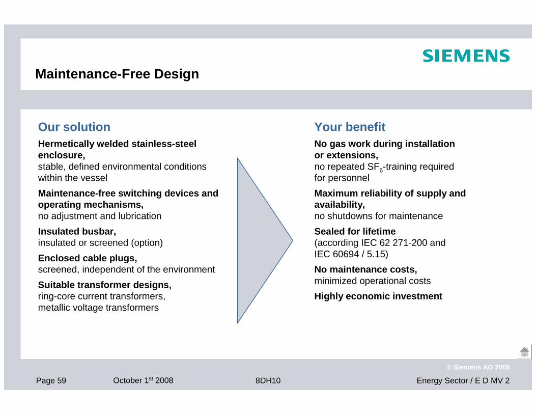
Maintenance-Free Design
Our solutionHermetically welded stainless-steel enclosure,stable, defined environmental conditions within the vessel
Maintenance-free switching devices and operating mechanisms,no adjustment and lubrication
Insulated busbar,insulated or screened (option)
Enclosed cable plugs,screened, independent of the environment
Suitable transformer designs,ring-core current transformers, metallic voltage transformers
Your benefitNo gas work during installation or extensions,no repeated SF6-training required for personnel
Maximum reliability of supply and availability,no shutdowns for maintenance
Sealed for lifetime(according IEC 62 271-200 and IEC 60694 / 5.15)
No maintenance costs,minimized operational costs
Highly economic investment
Page 60 October 1st 2008 Energy Sector / E D MV 28DH10
© Siemens AG 2008
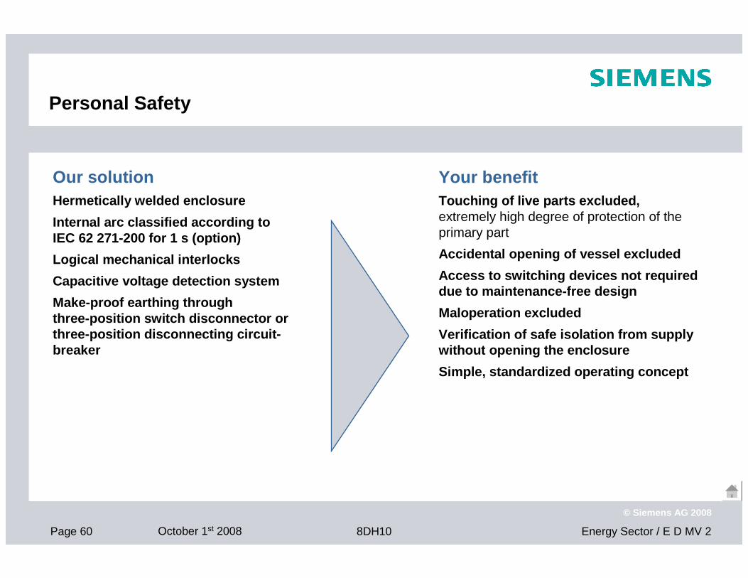
Personal Safety
Our solutionHermetically welded enclosure
Internal arc classified according to IEC 62 271-200 for 1 s (option)
Logical mechanical interlocks
Capacitive voltage detection system
Make-proof earthing throughthree-position switch disconnector or three-position disconnecting circuit-breaker
Your benefitTouching of live parts excluded,extremely high degree of protection of the primary part
Accidental opening of vessel excluded
Access to switching devices not required due to maintenance-free design
Maloperation excluded
Verification of safe isolation from supply without opening the enclosure
Simple, standardized operating concept
Page 61 October 1st 2008 Energy Sector / E D MV 28DH10
© Siemens AG 2008
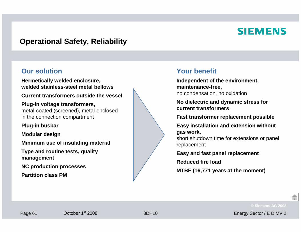
Operational Safety, Reliability
Our solutionHermetically welded enclosure, welded stainless-steel metal bellows
Current transformers outside the vessel
Plug-in voltage transformers,metal-coated (screened), metal-enclosed in the connection compartment
Plug-in busbar
Modular design
Minimum use of insulating material
Type and routine tests, quality management
NC production processes
Partition class PM
Your benefitIndependent of the environment, maintenance-free,no condensation, no oxidation
No dielectric and dynamic stress for current transformers
Fast transformer replacement possible
Easy installation and extension without gas work,short shutdown time for extensions or panel replacement
Easy and fast panel replacement
Reduced fire load
MTBF (16,771 years at the moment)
Page 62 October 1st 2008 Energy Sector / E D MV 28DH10
© Siemens AG 2008
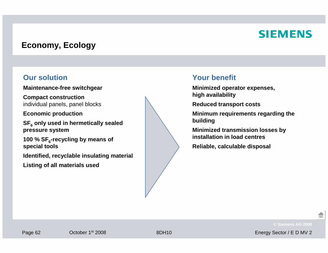
Economy, Ecology
Our solutionMaintenance-free switchgear
Compact constructionindividual panels, panel blocks
Economic production
SF6 only used in hermetically sealed pressure system
100 % SF6-recycling by means of special tools
Identified, recyclable insulating material
Listing of all materials used
Your benefitMinimized operator expenses, high availability
Reduced transport costs
Minimum requirements regarding the building
Minimized transmission losses by installation in load centres
Reliable, calculable disposal
Page 63 October 1st 2008 Energy Sector / E D MV 28DH10
© Siemens AG 2008
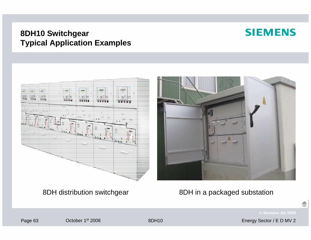
8DH10 Switchgear Typical Application Examples
8DH distribution switchgear 8DH in a packaged substation
Page 64 October 1st 2008 Energy Sector / E D MV 28DH10
© Siemens AG 2008
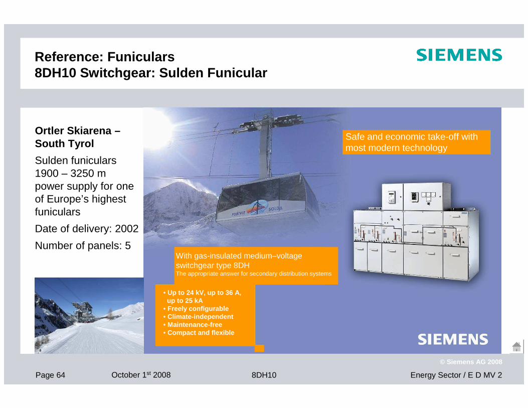
Reference: Funiculars 8DH10 Switchgear: Sulden Funicular
Ortler Skiarena –South Tyrol
Sulden funiculars 1900 – 3250 mpower supply for one of Europe’s highest funiculars
Date of delivery: 2002
Number of panels: 5With gas-insulated medium–voltage switchgear type 8DHThe appropriate answer for secondary distribution systems
• Up to 24 kV, up to 36 A, up to 25 kA
• Freely configurable• Climate-independent• Maintenance-free• Compact and flexible
Safe and economic take-off withmost modern technology
Page 65 October 1st 2008 Energy Sector / E D MV 28DH10
© Siemens AG 2008
MTBF
The term major failures and minor failures are taken from the CIGRE publication of the work group 13.06 “Reliability of High Voltage Switchgears”.
Definition:
� MTBFMeantime between failure
� Major failure (MF)Complete failure of a panel which causes the lack of one or more of its fundamentalfunctions.NOTE: A major failure will result in an immediate change in the system operating e.g. the backup protective equipment being required to remove the fault, or will result in mandatory removal from service for non scheduled maintenance (Intervention required within 30 minutes).
� Minor failure (mF)Failure of a panel other than a major failure or any failure, even complete, of a constructional element or a sub-assembly which does not cause a major failure of the panel.
� MTTFMeantime to failure
Page 66 October 1st 2008 Energy Sector / E D MV 28DH10
© Siemens AG 2008
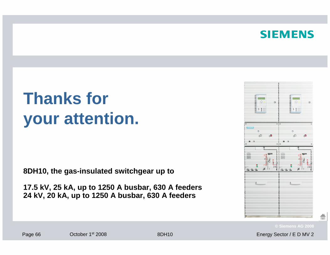
8DH10, the gas-insulated switchgear up to
17.5 kV, 25 kA, up to 1250 A busbar, 630 A feeders24 kV, 20 kA, up to 1250 A busbar, 630 A feeders
Thanks for your attention.