8600 compressor installation, operation and maintenance · pdf file8600 compressor...
TRANSCRIPT
8600 CompressorInstallation, Operation and
Maintenance Manual
8040707 Revision A
8600 CompressorInstallation, Operation and Maintenance Manual
Brooks Automation8040707 Revision A
Information provided within this document is subject to change without notice, and although believed to be accurate, Brooks Automation assumes no responsibility for any errors, omissions, or inaccuracies.
AcuLigner™, Align™, AquaTran™, AutoTeach™, ATR™, AXM™, Basic Blue™, BiSymmetrik™, CenterSmart™, Cool Solutions™, Crate to Operate™, e-RMA™, e-Spares™, e-Volution™, FastRegen™, FIXLOAD™, FrogLeg™, InLigner™, InCooler™, Interface™, Jet Engine™, LowProfile™, M2 Nano™, Mini-Ion™, PASIV™, PowerPak™, PerformanceBlue™, PowerPak™, PowerTools™, QuadraFly™, Radius™, Radient™, Radient Express™, Reliance™, Reliance ATR™, RetroEase™, SCARA™, SmartPM™, SPOTLevel™, Synetics™, The New Pathway to Productivity™, Time Optimized Trajectory™, Time Optimal Trajectory™, Time Optimized Path™, TopCooler™, TopLigner™, Ultimate Blue™, VAC-407™, VacuTran™, Vacuum Quality Monitor™, VQM™, Vacuum Quality Index™, VQI™, and the Brooks logo are trademarks of Brooks Automation, Inc. AcuTran®, AquaTrap®, Conductron®, Convectron®, the Cool Solutions logo, Cryodyne®, Cryotiger®, Cryo-Torr®, Fusion®, GOLDLink®, Granville-Phillips®, Guardian®, GUTS®, Helix®, Jet®, Leapfrog®, MagnaTran®, MapTrak®, Marathon®, Marathon 2®, Marathon Express®, Micro-Ion®, MiniConvectron®, On-Board®, Polycold®, Razor®, Simplicity Solutions®, the Simplicity Solutions logo, Stabil-Ion®, TrueBlue®, TurboPlus®, Vision®, Zaris®, and the Brooks Automation logo are registered U.S. trademarks of Brooks Automation, Inc. All other trademarks are properties of their respective owners.
© 2013 Brooks Automation, Inc. All Rights Reserved. The information included in this manual is Proprietary Information of Brooks Automation and is provided for the use of Brooks Automation customers only and cannot be used for distribution, reproduction, or sale without the express written permission of Brooks Automation. This information may be incorporated into the user’s documentation, however any changes made by the user to this information is the responsibility of the user.
For Technical Support:
Visit us online: www.brooks.com
January 11, 2013 Part Num 8040707 Revision A
This technology is subject to United States export Administration Regulations and authorized to the destination only; diversion contrary to U.S. law is prohibited.
Printed in the U.S.A.
Location GUTS® Contact Number
North America+1-800-FOR-GUTS (1-800-367-4887)+1-978-262-2900
Europe +49-1804-CALL-GUTS (+49-1804-2255-4887)
Japan +81-45-477-5980
China +86-21-5131-7066
Taiwan +886-3-5525225
Korea +82-31-288-2500
Singapore +65-6464-1481
8600 Compressor ContentsInstallation, Operation and Maintenance Manual
Brooks Automation 8040707Revision A i
Contents
Figures. . . . . . . . . . . . . . . . . . . . . . . . . . . . . . . . . . . . . . . . . . . . . . . . . . . . . . . . . . . . . . . . . . . v
Tables . . . . . . . . . . . . . . . . . . . . . . . . . . . . . . . . . . . . . . . . . . . . . . . . . . . . . . . . . . . . . . . . . . vii
Safety
Introduction . . . . . . . . . . . . . . . . . . . . . . . . . . . . . . . . . . . . . . . . . . . . . . . . . . . . . . . . . .1-2
Signal Word Descriptions . . . . . . . . . . . . . . . . . . . . . . . . . . . . . . . . . . . . . . . . . . . . . . .1-3
Safety Shape Descriptions. . . . . . . . . . . . . . . . . . . . . . . . . . . . . . . . . . . . . . . . . . . . . . .1-4
References . . . . . . . . . . . . . . . . . . . . . . . . . . . . . . . . . . . . . . . . . . . . . . . . . . . . . . . . . . . .1-4
Compressor Description
BROOKS-Cryogenics Helium Refrigeration System . . . . . . . . . . . . . . . . . . . . . . . .2-3
Specifications . . . . . . . . . . . . . . . . . . . . . . . . . . . . . . . . . . . . . . . . . . . . . . . . . . . . . . . . .2-4Dimensions . . . . . . . . . . . . . . . . . . . . . . . . . . . . . . . . . . . . . . . . . . . . . . . . . . . . .2-4Weight . . . . . . . . . . . . . . . . . . . . . . . . . . . . . . . . . . . . . . . . . . . . . . . . . . . . . . . . .2-7Electrical . . . . . . . . . . . . . . . . . . . . . . . . . . . . . . . . . . . . . . . . . . . . . . . . . . . . . . .2-7Cooling Water. . . . . . . . . . . . . . . . . . . . . . . . . . . . . . . . . . . . . . . . . . . . . . . . . . .2-8General. . . . . . . . . . . . . . . . . . . . . . . . . . . . . . . . . . . . . . . . . . . . . . . . . . . . . . . . .2-10
Component Description . . . . . . . . . . . . . . . . . . . . . . . . . . . . . . . . . . . . . . . . . . . . . . . .2-11Controller Front Panel Components . . . . . . . . . . . . . . . . . . . . . . . . . . . . . . . .2-14Controller Back Panel Components . . . . . . . . . . . . . . . . . . . . . . . . . . . . . . . .2-17Fuse Panel, Type 01 . . . . . . . . . . . . . . . . . . . . . . . . . . . . . . . . . . . . . . . . . . . . . .2-19Cooling Water INLET . . . . . . . . . . . . . . . . . . . . . . . . . . . . . . . . . . . . . . . . . . . .2-20Cooling Water OUTLET . . . . . . . . . . . . . . . . . . . . . . . . . . . . . . . . . . . . . . . . . .2-21Cryopump Electrical Outlet . . . . . . . . . . . . . . . . . . . . . . . . . . . . . . . . . . . . . . .2-21Helium Gas Charge Control Valve . . . . . . . . . . . . . . . . . . . . . . . . . . . . . . . . .2-21
Contents 8600 CompressorInstallation, Operation and Maintenance Manual
8040707 Brooks Automationii Revision A
Helium Pressure Gauge . . . . . . . . . . . . . . . . . . . . . . . . . . . . . . . . . . . . . . . . . .2-21Helium Return Line Coupling . . . . . . . . . . . . . . . . . . . . . . . . . . . . . . . . . . . . .2-22Helium Supply Line Coupling. . . . . . . . . . . . . . . . . . . . . . . . . . . . . . . . . . . . .2-22Power Connector . . . . . . . . . . . . . . . . . . . . . . . . . . . . . . . . . . . . . . . . . . . . . . . .2-22
Unpacking and Inspection
Shipping Carton Inspection . . . . . . . . . . . . . . . . . . . . . . . . . . . . . . . . . . . . . . . . . . . . .3-2
Compressor Inspection . . . . . . . . . . . . . . . . . . . . . . . . . . . . . . . . . . . . . . . . . . . . . . . . .3-2Compressor. . . . . . . . . . . . . . . . . . . . . . . . . . . . . . . . . . . . . . . . . . . . . . . . . . . . .3-2Static Helium System Pressure Verification. . . . . . . . . . . . . . . . . . . . . . . . . .3-2
Shipping Carton Contents . . . . . . . . . . . . . . . . . . . . . . . . . . . . . . . . . . . . . . . . . . . . . .3-3
Installation
Installation Tasks . . . . . . . . . . . . . . . . . . . . . . . . . . . . . . . . . . . . . . . . . . . . . . . . . . . . . .4-2
Environmental Specifications. . . . . . . . . . . . . . . . . . . . . . . . . . . . . . . . . . . . . . . . . . . .4-3
Supply and Return Water Line Connections . . . . . . . . . . . . . . . . . . . . . . . . . . . . . . .4-4Prerequisites to Installing Supply and Return Water Line Connections. .4-4Installing Hard Water Lines . . . . . . . . . . . . . . . . . . . . . . . . . . . . . . . . . . . . . . .4-5Installing Flexible Water Lines. . . . . . . . . . . . . . . . . . . . . . . . . . . . . . . . . . . . .4-6
Electrical Connections for Type 01 8600 Compressor . . . . . . . . . . . . . . . . . . . . . . .4-7
Electrical Connections for Type 02 8600 Compressor . . . . . . . . . . . . . . . . . . . . . . .4-8Wiring Procedure for Remote Connector. . . . . . . . . . . . . . . . . . . . . . . . . . . .4-9
Connecting and Disconnecting Helium Flex Lines. . . . . . . . . . . . . . . . . . . . . . . . . .4-11Connecting Flexible Helium Lines . . . . . . . . . . . . . . . . . . . . . . . . . . . . . . . . .4-11Disconnecting Helium Flex Lines . . . . . . . . . . . . . . . . . . . . . . . . . . . . . . . . . .4-13
Cryo-Torr 20HP Cryopump Connections . . . . . . . . . . . . . . . . . . . . . . . . . . . . . . . . .4-14
Pre-operation Checklist. . . . . . . . . . . . . . . . . . . . . . . . . . . . . . . . . . . . . . . . . . . . . . . . .4-16
8600 Compressor Storage . . . . . . . . . . . . . . . . . . . . . . . . . . . . . . . . . . . . . . . . . . . . . . .4-18
Operation
Adjusting System Helium Pressure . . . . . . . . . . . . . . . . . . . . . . . . . . . . . . . . . . . . . .5-2
"OFF" Condition Helium System Pressure Verification. . . . . . . . . . . . . . . . . . . . . .5-3
Compressor Operation . . . . . . . . . . . . . . . . . . . . . . . . . . . . . . . . . . . . . . . . . . . . . . . . .5-4Turn On the Type 01 Compressor . . . . . . . . . . . . . . . . . . . . . . . . . . . . . . . . . .5-5
8600 Compressor ContentsInstallation, Operation and Maintenance Manual
Brooks Automation 8040707Revision A iii
Turn On the Type 02 Compressor (Use Local Mode). . . . . . . . . . . . . . . . . .5-5Turn Off the Type 02 Compressor. . . . . . . . . . . . . . . . . . . . . . . . . . . . . . . . . .5-6 Return the Type 02 Compressor to Remote Mode. . . . . . . . . . . . . . . . . . . .5-6Document Compressor Performance . . . . . . . . . . . . . . . . . . . . . . . . . . . . . . .5-6
Secondary Power: CP1 Breaker and Troubleshooting Diagnostic Problems . . . .5-8
Replacement of Helium Circuit Components . . . . . . . . . . . . . . . . . . . . . . . . . . . . . .5-9
Maintenance
Scheduled Maintenance . . . . . . . . . . . . . . . . . . . . . . . . . . . . . . . . . . . . . . . . . . . . . . . .6-2Suggested Maintenance Equipment . . . . . . . . . . . . . . . . . . . . . . . . . . . . . . . .6-2Adsorber Replacement . . . . . . . . . . . . . . . . . . . . . . . . . . . . . . . . . . . . . . . . . . .6-2
Adjusting System Helium Pressure . . . . . . . . . . . . . . . . . . . . . . . . . . . . . . . . . . . . . .6-6Reducing Helium Pressure. . . . . . . . . . . . . . . . . . . . . . . . . . . . . . . . . . . . . . . .6-8Increasing Helium Pressure . . . . . . . . . . . . . . . . . . . . . . . . . . . . . . . . . . . . . . .6-9
Appendices
Appendix A: Customer Brooks Automation Technical Support Information. . .7-2
Appendix B: Flow Diagram . . . . . . . . . . . . . . . . . . . . . . . . . . . . . . . . . . . . . . . . . . . . .7-3
Appendix C: Troubleshooting Procedures. . . . . . . . . . . . . . . . . . . . . . . . . . . . . . . . .7-6Technical Inquiries. . . . . . . . . . . . . . . . . . . . . . . . . . . . . . . . . . . . . . . . . . . . . . .7-68600 Compressor Error Messages . . . . . . . . . . . . . . . . . . . . . . . . . . . . . . . . . .7-6Troubleshooting when the NORMAL/C20 Switch is Set to NORMAL . .7-7Troubleshooting when the NORMAL/C20 Switch is Set to C/20 . . . . . . .7-8
Appendix D: Troubleshooting Procedures, Type 02 Only . . . . . . . . . . . . . . . . . . .7-13Alarm Sounds Continuously When Compressor is Turned On . . . . . . . . .7-13Alarm Code Description . . . . . . . . . . . . . . . . . . . . . . . . . . . . . . . . . . . . . . . . . .7-14
Appendix E: Electrical Schematic for the 8600 Compressor . . . . . . . . . . . . . . . . . .7-17Introduction . . . . . . . . . . . . . . . . . . . . . . . . . . . . . . . . . . . . . . . . . . . . . . . . . . . .7-17Remote/Response Wiring . . . . . . . . . . . . . . . . . . . . . . . . . . . . . . . . . . . . . . . .7-18
Index . . . . . . . . . . . . . . . . . . . . . . . . . . . . . . . . . . . . . . . . . . . . . . . . . . . . . . . . . . . . . . . . . . . . .1

Contents 8600 CompressorInstallation, Operation and Maintenance Manual
8040707 Brooks Automationiv Revision A
This Page Intentionally Left Blank
8600 Compressor FiguresInstallation, Operation and Maintenance Manual
Brooks Automation 8040707Revision A v
Figures
Figure Title Page
2-1 The 8600 Compressor, Type 01 and Type 02 . . . . . . . . . . . . . . . . . . . . . . . . .2-32-2 8600 Compressor Side and Front Dimensions, Type 01. . . . . . . . . . . . . . . .2-42-3 8600 Compressor Side and Front Dimentions, Type 02 . . . . . . . . . . . . . . . .2-52-4 8600 Compressor Rear Dimensions, Type 01. . . . . . . . . . . . . . . . . . . . . . . . .2-62-5 8600 Compressor Rear Dimentions, Type 02 . . . . . . . . . . . . . . . . . . . . . . . . .2-72-6 Water Flow Rate Versus Pressure Drop . . . . . . . . . . . . . . . . . . . . . . . . . . . . .2-92-7 8600 Compressor Front View Component Locations, Type 01. . . . . . . . . .2-112-8 8600 Compressor Front View Component Locations, Type 02. . . . . . . . . .2-122-9 8600 Compressor Rear View Component Locations, Type 01 . . . . . . . . . .2-132-10 8600 Compressor Rear View Component Locations, Type 02 . . . . . . . . . .2-142-11 8600 Compressor Controller Front Panel, Type 01 . . . . . . . . . . . . . . . . . . . .2-152-12 8600 Compressor Controller Front Panel, Type 02 . . . . . . . . . . . . . . . . . . . .2-152-13 8600 Compressor Controller Back Panel, Type 01 . . . . . . . . . . . . . . . . . . . .2-172-14 8600 Compressor Controller Back Panel, Type 02 . . . . . . . . . . . . . . . . . . . .2-182-15 Fuse Panel . . . . . . . . . . . . . . . . . . . . . . . . . . . . . . . . . . . . . . . . . . . . . . . . . . . . . .2-20
4-1 8600 Compressor Installation Flowchart . . . . . . . . . . . . . . . . . . . . . . . . . . . .4-24-2 Clearance Requirements, Top View . . . . . . . . . . . . . . . . . . . . . . . . . . . . . . . .4-34-3 Connector Parts . . . . . . . . . . . . . . . . . . . . . . . . . . . . . . . . . . . . . . . . . . . . . . . . .4-94-4 Connecting/Disconnecting Helium Flex Line Couplings . . . . . . . . . . . . . .4-124-5 Cryo-Torr 20HP Cryopump Connections . . . . . . . . . . . . . . . . . . . . . . . . . . .4-14
5-1 Operation Ready . . . . . . . . . . . . . . . . . . . . . . . . . . . . . . . . . . . . . . . . . . . . . . . .5-5
6-1 Disconnecting Self-Sealing Couplings . . . . . . . . . . . . . . . . . . . . . . . . . . . . . .6-46-2 Disconnecting the Flexible Line from the Adsorber Inlet . . . . . . . . . . . . . .6-56-3 Adsorber Maintenance Record Label . . . . . . . . . . . . . . . . . . . . . . . . . . . . . . .6-56-4 Component Locations Behind Front Panel . . . . . . . . . . . . . . . . . . . . . . . . . .6-76-5 Equipment to Add Helium to the System . . . . . . . . . . . . . . . . . . . . . . . . . . .6-86-6 Helium Pressure Control Components, Type 02 Shown . . . . . . . . . . . . . .6-9
7-1 8600 Compressor Flow Diagram . . . . . . . . . . . . . . . . . . . . . . . . . . . . . . . . . . .7-47-2 8600 Compressor Elapsed Time Meter/Error Message Display, Type 01 7-7
Figures 8600 CompressorInstallation, Operation and Maintenance Manual
8040707 Brooks Automationvi Revision A
7-3 Reverse Phase or Phase Loss . . . . . . . . . . . . . . . . . . . . . . . . . . . . . . . . . . . . . .7-137-4 Remote Response Interface and Wiring Diagram, Type 01. . . . . . . . . . . . .7-187-5 Remote Connections, Type 02 . . . . . . . . . . . . . . . . . . . . . . . . . . . . . . . . . . . . .7-197-6 Remote/Response Pin Assignments, Type 02. . . . . . . . . . . . . . . . . . . . . . . .7-197-7 8600 Compressor Electrical Schematic. . . . . . . . . . . . . . . . . . . . . . . . . . . . . .7-21
8600 Compressor TablesInstallation, Operation and Maintenance Manual
Brooks Automation 8040707Revision A vii
Tables
Table Title Page
1-1 Safety Signal Words. . . . . . . . . . . . . . . . . . . . . . . . . . . . . . . . . . . . . . . . . . . . . .1-31-2 Safety Shapes . . . . . . . . . . . . . . . . . . . . . . . . . . . . . . . . . . . . . . . . . . . . . . . . . . .1-4
2-1 Electrical Input Specifications . . . . . . . . . . . . . . . . . . . . . . . . . . . . . . . . . . . . .2-72-2 Cooling Water Specifications . . . . . . . . . . . . . . . . . . . . . . . . . . . . . . . . . . . . . .2-82-3 General Compressor Operating Specifications . . . . . . . . . . . . . . . . . . . . . . .2-102-4 Cryo-Torr 20HP Cryopump Electrical Outlet Pin Assignments. . . . . . . . .2-21
3-1 Shipping List. . . . . . . . . . . . . . . . . . . . . . . . . . . . . . . . . . . . . . . . . . . . . . . . . . . .3-3
4-1 Environmental Specifications. . . . . . . . . . . . . . . . . . . . . . . . . . . . . . . . . . . . . .4-34-2 Flexible Helium Supply and Return Lines. . . . . . . . . . . . . . . . . . . . . . . . . . .4-11
5-1 8600 Compressor Helium ("OFF" Condition) Charge . . . . . . . . . . . . . . . . .5-3
6-1 Suggested Maintenance Equipment . . . . . . . . . . . . . . . . . . . . . . . . . . . . . . . .6-2
7-1 8600 Compressor Safety Devices . . . . . . . . . . . . . . . . . . . . . . . . . . . . . . . . . . .7-5
7-1 Alarm Status Table. . . . . . . . . . . . . . . . . . . . . . . . . . . . . . . . . . . . . . . . . . . . . . .7-67-2 8600 Compressor Error Messages . . . . . . . . . . . . . . . . . . . . . . . . . . . . . . . . . .7-97-3 Operating Log. . . . . . . . . . . . . . . . . . . . . . . . . . . . . . . . . . . . . . . . . . . . . . . . . . .7-127-4 Basic Control Assembly Legend . . . . . . . . . . . . . . . . . . . . . . . . . . . . . . . . . . .7-177-5 Response (No-Voltage/Dry Contact) . . . . . . . . . . . . . . . . . . . . . . . . . . . . . . .7-207-6 System Response/Failure Response Max. Switching Capacity . . . . . . . . .7-20

Tables 8600 CompressorInstallation, Operation and Maintenance Manual
8040707 Brooks Automationviii Revision A
This Page Intentionally Left Blank
8600 CompressorInstallation, Operation and Maintenance Manual
Brooks Automation 8040707Revision A 1-1
1 Safety
Overview
This section describes safety conventions for the Brooks Automation Product. All personnel involved in the operation or maintenance of the product must be familiar with the safety precautions outlined in this section.
NOTE: These safety recommendations are basic guidelines. If the facility where the Prod-uct is installed has additional safety guidelines they should be followed as well, along with the applicable national and international safety codes.
Chapter Contents
Introduction . . . . . . . . . . . . . . . . . . . . . . . . . . . . . . . . . . . . . . . . . . . . . . . . . . . . . . . . . .1-2
Signal Word Descriptions . . . . . . . . . . . . . . . . . . . . . . . . . . . . . . . . . . . . . . . . . . . . . . .1-3
Safety Shape Descriptions. . . . . . . . . . . . . . . . . . . . . . . . . . . . . . . . . . . . . . . . . . . . . . .1-4
References . . . . . . . . . . . . . . . . . . . . . . . . . . . . . . . . . . . . . . . . . . . . . . . . . . . . . . . . . . . .1-4
Safety 8600 CompressorIntroduction Installation, Operation and Maintenance Manual
8040707 Brooks Automation1-2 Revision A
Introduction
Follow all safety precautions during installation, normal operation, and when servic-ing BROOKS-Cryogenics products.
This chapter explains the safety conventions used throughout this manual. BROOKS-Cryogenics uses a specific format for cautions and warnings, which includes standard signal words and safety shapes.
See also the Customer Support appendix or call your local Customer Support Center for assistance.
8600 Compressor SafetyInstallation, Operation and Maintenance Manual Signal Word Descriptions
Brooks Automation 8040707Revision A 1-3
Signal Word Descriptions
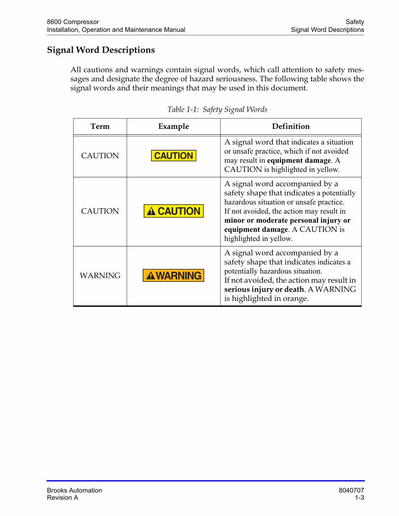
All cautions and warnings contain signal words, which call attention to safety mes-sages and designate the degree of hazard seriousness. The following table shows the signal words and their meanings that may be used in this document.
Table 1-1: Safety Signal Words
Term Example Definition
CAUTION
A signal word that indicates a situation or unsafe practice, which if not avoided may result in equipment damage. A CAUTION is highlighted in yellow.
CAUTION
A signal word accompanied by a safety shape that indicates a potentially hazardous situation or unsafe practice. If not avoided, the action may result in minor or moderate personal injury or equipment damage. A CAUTION is highlighted in yellow.
WARNING
A signal word accompanied by a safety shape that indicates indicates a potentially hazardous situation. If not avoided, the action may result in serious injury or death. A WARNING is highlighted in orange.
Safety 8600 CompressorSafety Shape Descriptions Installation, Operation and Maintenance Manual
8040707 Brooks Automation1-4 Revision A
Safety Shape Descriptions
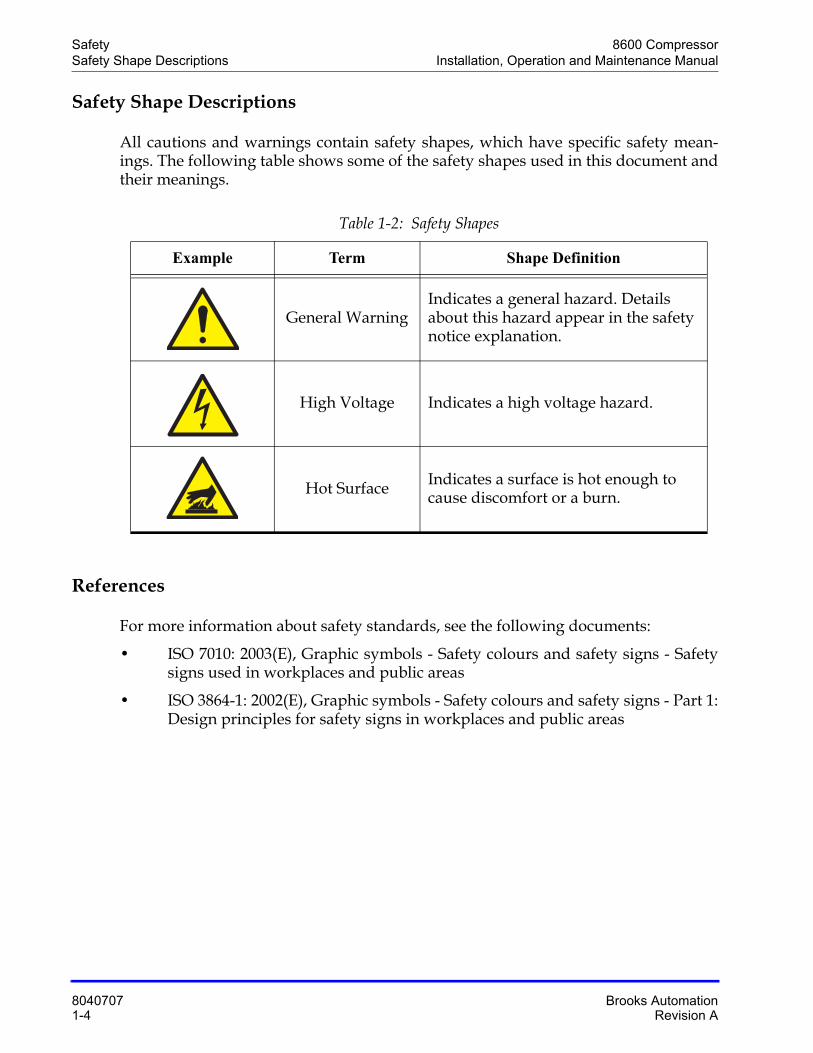
All cautions and warnings contain safety shapes, which have specific safety mean-ings. The following table shows some of the safety shapes used in this document and their meanings.
References
For more information about safety standards, see the following documents:
• ISO 7010: 2003(E), Graphic symbols - Safety colours and safety signs - Safety signs used in workplaces and public areas
• ISO 3864-1: 2002(E), Graphic symbols - Safety colours and safety signs - Part 1: Design principles for safety signs in workplaces and public areas
Table 1-2: Safety Shapes
Example Term Shape Definition
General WarningIndicates a general hazard. Details about this hazard appear in the safety notice explanation.
High Voltage Indicates a high voltage hazard.
Hot Surface Indicates a surface is hot enough to cause discomfort or a burn.
8600 CompressorInstallation, Operation and Maintenance Manual
Brooks Automation 8040707Revision A 2-1
2 Compressor Description
Overview
This manual provides the information required to install, operate, and maintain the BROOKS-Cryogenics 8600 Compressor.
NOTE: All personnel with installation, operation, and maintenance responsibilities should become familiar with the contents of both the 8600 Compressor Installation, Operation, Maintenance Instructions, and appropriate cryopump manuals to ensure safe, high quality and reliable system performance.
Refer to Appendix A: Customer Brooks Automation Technical Support Informationon page 7-2 to contact the local Customer Support Center for information on connect-ing the 8600 Compressors to a manifold with other BROOKS-Cryogenics compres-sors.
NOTE: This manual addresses both Type 01 and Type 02 8600 Compressors, unless other-wise noted.
Chapter Contents
BROOKS-Cryogenics Helium Refrigeration System . . . . . . . . . . . . . . . . . . . . . . . .2-3
Specifications . . . . . . . . . . . . . . . . . . . . . . . . . . . . . . . . . . . . . . . . . . . . . . . . . . . . . . . . .2-4Dimensions . . . . . . . . . . . . . . . . . . . . . . . . . . . . . . . . . . . . . . . . . . . . . . . . . . . . .2-4Weight . . . . . . . . . . . . . . . . . . . . . . . . . . . . . . . . . . . . . . . . . . . . . . . . . . . . . . . . .2-7Cooling Water. . . . . . . . . . . . . . . . . . . . . . . . . . . . . . . . . . . . . . . . . . . . . . . . . . .2-8General. . . . . . . . . . . . . . . . . . . . . . . . . . . . . . . . . . . . . . . . . . . . . . . . . . . . . . . . .2-10
Component Description . . . . . . . . . . . . . . . . . . . . . . . . . . . . . . . . . . . . . . . . . . . . . . . .2-11Controller Front Panel Components . . . . . . . . . . . . . . . . . . . . . . . . . . . . . . . .2-14Controller Back Panel Components . . . . . . . . . . . . . . . . . . . . . . . . . . . . . . . .2-17Fuse Panel, Type 01 . . . . . . . . . . . . . . . . . . . . . . . . . . . . . . . . . . . . . . . . . . . . . .2-19Cooling Water INLET . . . . . . . . . . . . . . . . . . . . . . . . . . . . . . . . . . . . . . . . . . . .2-20Cooling Water INLET . . . . . . . . . . . . . . . . . . . . . . . . . . . . . . . . . . . . . . . . . . . .2-20
Compressor Description 8600 CompressorInstallation, Operation and Maintenance Manual
8040707 Brooks Automation2-2 Revision A
Cooling Water OUTLET . . . . . . . . . . . . . . . . . . . . . . . . . . . . . . . . . . . . . . . . . .2-21Helium Gas Charge Control Valve . . . . . . . . . . . . . . . . . . . . . . . . . . . . . . . . .2-21Helium Pressure Gauge . . . . . . . . . . . . . . . . . . . . . . . . . . . . . . . . . . . . . . . . . .2-21Helium Return Line Coupling . . . . . . . . . . . . . . . . . . . . . . . . . . . . . . . . . . . . .2-22Helium Supply Line Coupling. . . . . . . . . . . . . . . . . . . . . . . . . . . . . . . . . . . . .2-22Power Connector . . . . . . . . . . . . . . . . . . . . . . . . . . . . . . . . . . . . . . . . . . . . . . . .2-22
8600 Compressor Compressor DescriptionInstallation, Operation and Maintenance Manual BROOKS-Cryogenics Helium Refrigeration System
Brooks Automation 8040707Revision A 2-3
BROOKS-CryogenicsHelium Refrigeration System
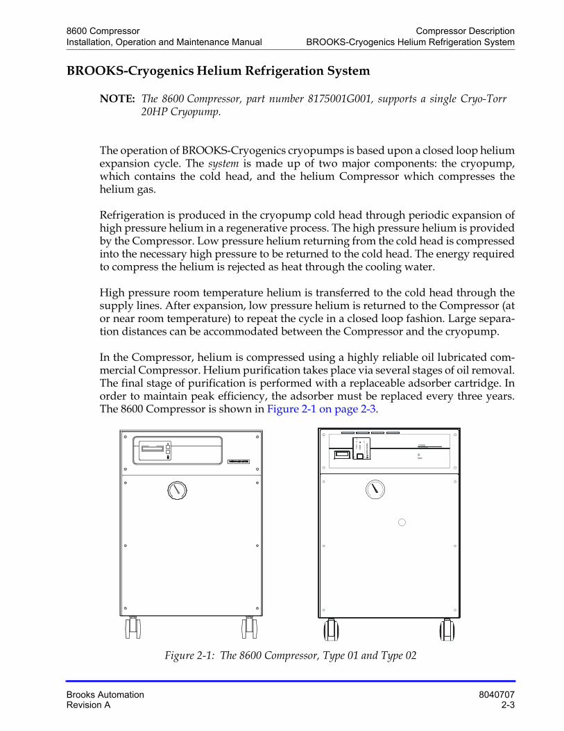
NOTE: The 8600 Compressor, part number 8175001G001, supports a single Cryo-Torr 20HP Cryopump.
The operation of BROOKS-Cryogenics cryopumps is based upon a closed loop helium expansion cycle. The system is made up of two major components: the cryopump, which contains the cold head, and the helium Compressor which compresses the helium gas.
Refrigeration is produced in the cryopump cold head through periodic expansion of high pressure helium in a regenerative process. The high pressure helium is provided by the Compressor. Low pressure helium returning from the cold head is compressed into the necessary high pressure to be returned to the cold head. The energy required to compress the helium is rejected as heat through the cooling water.
High pressure room temperature helium is transferred to the cold head through the supply lines. After expansion, low pressure helium is returned to the Compressor (at or near room temperature) to repeat the cycle in a closed loop fashion. Large separa-tion distances can be accommodated between the Compressor and the cryopump.
In the Compressor, helium is compressed using a highly reliable oil lubricated com-mercial Compressor. Helium purification takes place via several stages of oil removal. The final stage of purification is performed with a replaceable adsorber cartridge. In order to maintain peak efficiency, the adsorber must be replaced every three years. The 8600 Compressor is shown in Figure 2-1 on page 2-3.
Figure 2-1: The 8600 Compressor, Type 01 and Type 02
8600Compressor
CTI-CRYOGENICSHELIX TECHNOLOGY CORPORATION
12345678
RSTCOM
PWR
RDY
Ch1RUN
STS
C‚R‚O‚o‚u R‚s
Compressor Description 8600 CompressorSpecifications Installation, Operation and Maintenance Manual
8040707 Brooks Automation2-4 Revision A
Specifications
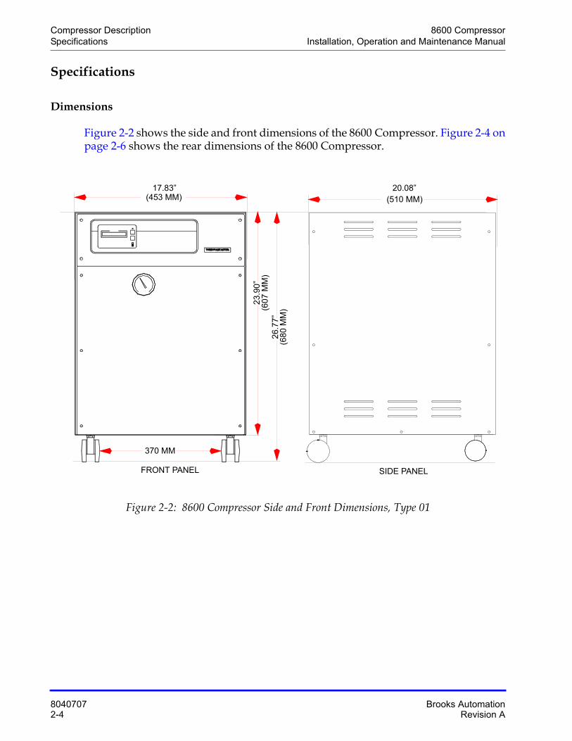
Dimensions
Figure 2-2 shows the side and front dimensions of the 8600 Compressor. Figure 2-4 on page 2-6 shows the rear dimensions of the 8600 Compressor.
Figure 2-2: 8600 Compressor Side and Front Dimensions, Type 01
SIDE PANELFRONT PANEL
17.83”(453 MM)
26.
77”
(680
MM
)
23.
90”
(607
MM
)
20.08”(510 MM)
370 MM
8600 Compressor Compressor DescriptionInstallation, Operation and Maintenance Manual Specifications
Brooks Automation 8040707Revision A 2-5
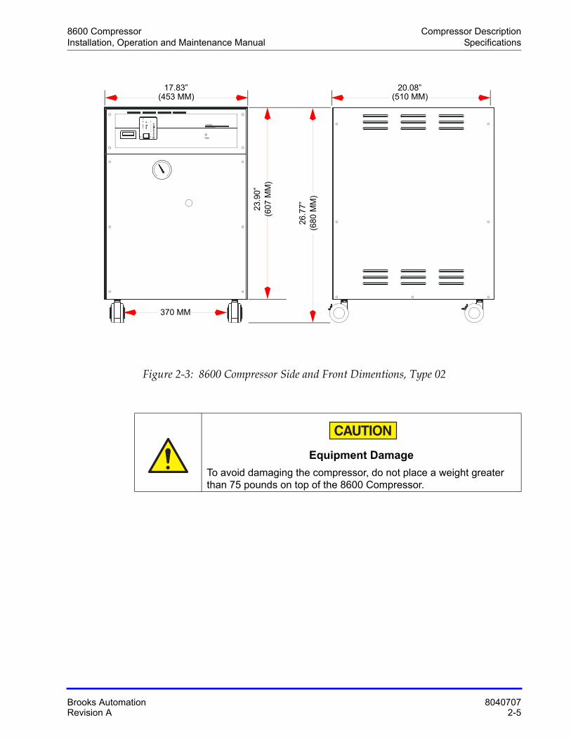
Figure 2-3: 8600 Compressor Side and Front Dimentions, Type 02
Equipment Damage
To avoid damaging the compressor, do not place a weight greater than 75 pounds on top of the 8600 Compressor.
8600Compressor
CTI-CRYOGENICSHELIX TECHNOLOGY CORPORATION
12345678
RSTCOM
PWR
RDY
Ch1RUN
STS
C‚R‚O‚o‚u R‚s
23.9
0”
(453 MM)17.83”
(510 MM)20.08”
(607
MM
)
26.7
7”(6
80 M
M)
370 MM
Compressor Description 8600 CompressorSpecifications Installation, Operation and Maintenance Manual
8040707 Brooks Automation2-6 Revision A
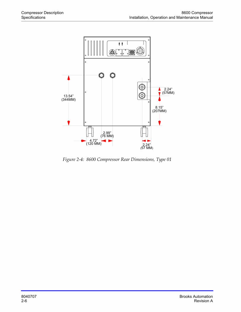
Figure 2-4: 8600 Compressor Rear Dimensions, Type 01
2.24”(57MM)
8.15”(207MM)
4.72”(120 MM)
2.99”(76 MM)
2.24”(57 MM)
13.54”(344MM)
8600 Compressor Compressor DescriptionInstallation, Operation and Maintenance Manual Specifications
Brooks Automation 8040707Revision A 2-7
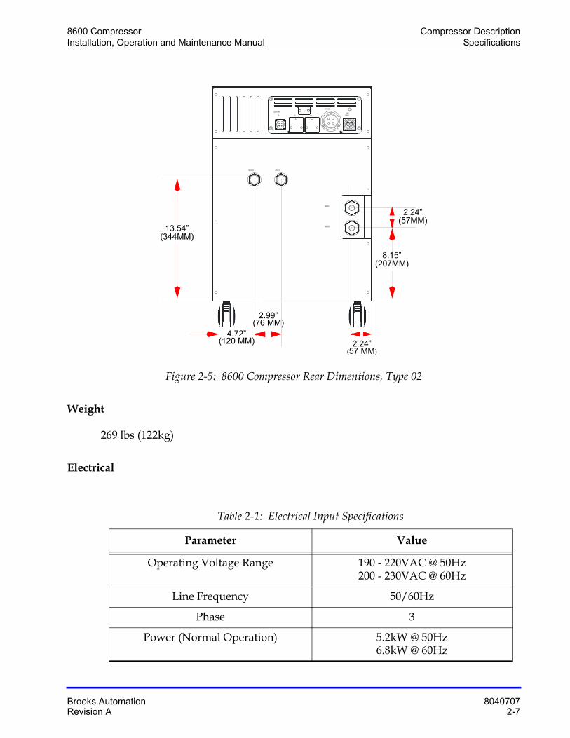
Figure 2-5: 8600 Compressor Rear Dimentions, Type 02
Weight
269 lbs (122kg)
Electrical
Table 2-1: Electrical Input Specifications
Parameter Value
Operating Voltage Range 190 - 220VAC @ 50Hz200 - 230VAC @ 60Hz
Line Frequency 50/60Hz
Phase 3
Power (Normal Operation) 5.2kW @ 50Hz6.8kW @ 60Hz
WATER OUT
WATER IN
SUPPLY GASRETURN GAS
REMOTERESPONSE
INPUT POWER
NO. 3NO. 2NO. 1
COLD HEAD POWER
2.24”(57MM)
8.15”(207MM)
4.72”(120 MM)
2.99”(76 MM)
2.24”(57 MM)
13.54”(344MM)
Compressor Description 8600 CompressorSpecifications Installation, Operation and Maintenance Manual
8040707 Brooks Automation2-8 Revision A
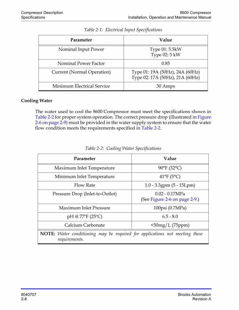
Cooling Water
The water used to cool the 8600 Compressor must meet the specifications shown in Table 2-2 for proper system operation. The correct pressure drop (illustrated in Figure 2-6 on page 2-9) must be provided in the water supply system to ensure that the water flow condition meets the requirements specified in Table 2-2.
Nominal Input Power Type 01: 5.5kWType 02: 5 kW
Nominal Power Factor 0.85
Current (Normal Operation) Type 01: 19A (50Hz), 24A (60Hz)Type 02: 17A (50Hz), 21A (60Hz)
Minimum Electrical Service 30 Amps
Table 2-2: Cooling Water Specifications
Parameter Value
Maximum Inlet Temperature 90°F (32°C)
Minimum Inlet Temperature 41°F (5°C)
Flow Rate 1.0 - 3.3gpm (5 - 15Lpm)
Pressure Drop (Inlet-to-Outlet) 0.02 - 0.17MPa (See Figure 2-6 on page 2-9.)
Maximum Inlet Pressure 100psi (0.7MPa)
pH @ 77ºF (25ºC) 6.5 - 8.0
Calcium Carbonate <50mg/L (75ppm)
NOTE: Water conditioning may be required for applications not meeting these requirements.
Table 2-1: Electrical Input Specifications
Parameter Value
8600 Compressor Compressor DescriptionInstallation, Operation and Maintenance Manual Specifications
Brooks Automation 8040707Revision A 2-9
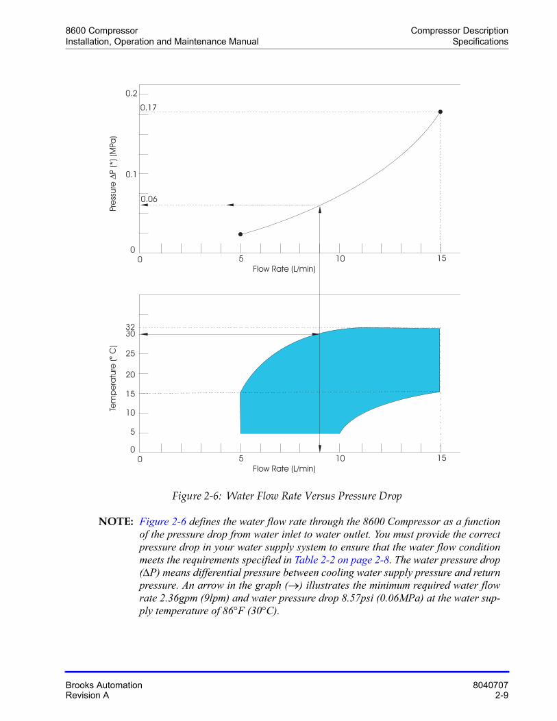
Figure 2-6: Water Flow Rate Versus Pressure Drop
NOTE: Figure 2-6 defines the water flow rate through the 8600 Compressor as a function of the pressure drop from water inlet to water outlet. You must provide the correct pressure drop in your water supply system to ensure that the water flow condition meets the requirements specified in Table 2-2 on page 2-8. The water pressure drop (P) means differential pressure between cooling water supply pressure and return pressure. An arrow in the graph () illustrates the minimum required water flow rate 2.36gpm (9lpm) and water pressure drop 8.57psi (0.06MPa) at the water sup-ply temperature of 86°F (30°C).
Flow Rate (L/min)
Tem
pe
ratu
re(
C)
°
0
5
20
30
15
25
32
10
0 5 10 15
Flow Rate (L/min)
Pre
ssure
P(*
)(M
Pa)
Δ
0
0.2
0.17
0.1
0 5 10 15
0.06
Compressor Description 8600 CompressorSpecifications Installation, Operation and Maintenance Manual
8040707 Brooks Automation2-10 Revision A
General
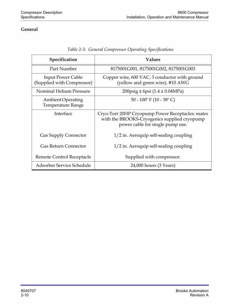
Table 2-3: General Compressor Operating Specifications
Specification Values
Part Number 8175001G001, 8175001G002, 8175001G003
Input Power Cable(Supplied with Compressor)
Copper wire, 600 VAC, 3 conductor with ground (yellow and green wire), #10 AWG
Nominal Helium Pressure 200psig ± 6psi (1.4 ± 0.04MPa)
Ambient Operating Temperature Range
50 - 100º F (10 - 38º C)
Interface
Gas Supply Connector
Gas Return Connector
Remote Control Receptacle
Cryo-Torr 20HP Cryopump Power Receptacles: mates with the BROOKS-Cryogenics supplied cryopump
power cable for single pump use.
1/2 in. Aeroquip self-sealing coupling
1/2 in. Aeroquip self-sealing coupling
Supplied with compressor.
Adsorber Service Schedule 24,000 hours (3 Years)
8600 Compressor Compressor DescriptionInstallation, Operation and Maintenance Manual Component Description
Brooks Automation 8040707Revision A 2-11
Component Description
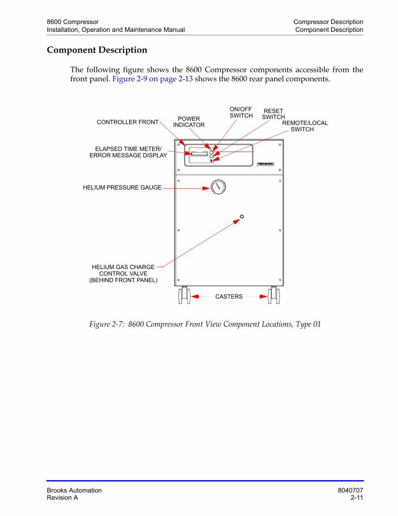
The following figure shows the 8600 Compressor components accessible from the front panel. Figure 2-9 on page 2-13 shows the 8600 rear panel components.
Figure 2-7: 8600 Compressor Front View Component Locations, Type 01
HELIUM GAS CHARGE
POWER
ON/OFF RESET
REMOTE/LOCALSWITCH
INDICATOR
SWITCH SWITCH
HELIUM PRESSURE GAUGE
ELAPSED TIME METER/ERROR MESSAGE DISPLAY
CONTROLLER FRONT
CONTROL VALVE(BEHIND FRONT PANEL)
CASTERS
Compressor Description 8600 CompressorComponent Description Installation, Operation and Maintenance Manual
8040707 Brooks Automation2-12 Revision A
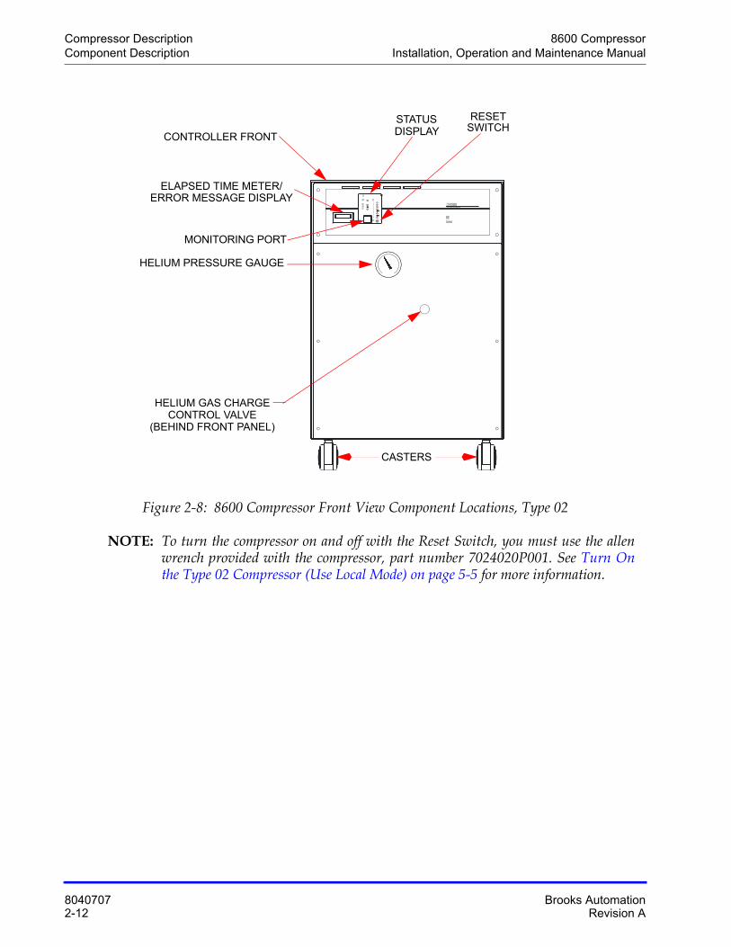
Figure 2-8: 8600 Compressor Front View Component Locations, Type 02
NOTE: To turn the compressor on and off with the Reset Switch, you must use the allen wrench provided with the compressor, part number 7024020P001. See Turn Onthe Type 02 Compressor (Use Local Mode) on page 5-5 for more information.
8600Compressor
CTI-CRYOGENICSHELIX TECHNOLOGY CORPORATION
12345678
RSTCOM
PWR
RDY
Ch1RUN
STS
C‚R‚O‚o‚u R‚s
HELIUM GAS CHARGE
RESET SWITCH
HELIUM PRESSURE GAUGE
ELAPSED TIME METER/ERROR MESSAGE DISPLAY
CONTROLLER FRONT
CONTROL VALVE(BEHIND FRONT PANEL)
CASTERS
MONITORING PORT
STATUSDISPLAY
8600 Compressor Compressor DescriptionInstallation, Operation and Maintenance Manual Component Description
Brooks Automation 8040707Revision A 2-13
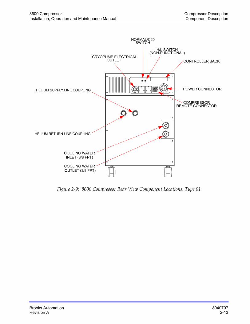
Figure 2-9: 8600 Compressor Rear View Component Locations, Type 01
CRYOPUMP ELECTRICAL
COOLING WATER
HELIUM SUPPLY LINE COUPLING
INLET (3/8 FPT)
COOLING WATER OUTLET (3/8 FPT)
HELIUM RETURN LINE COUPLING
OUTLET
NORMAL/C20SWITCH
H/L SWITCH(NON-FUNCTIONAL)
POWER CONNECTOR
COMPRESSORREMOTE CONNECTOR
CONTROLLER BACK
Compressor Description 8600 CompressorComponent Description Installation, Operation and Maintenance Manual
8040707 Brooks Automation2-14 Revision A
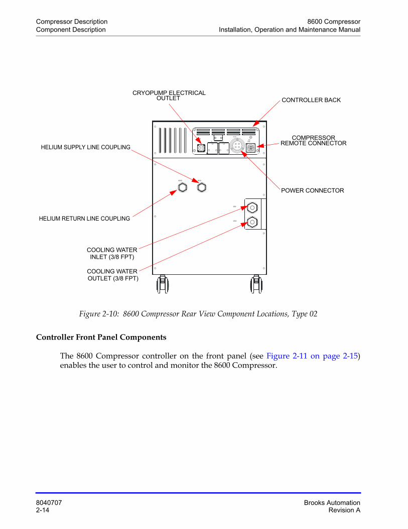
Figure 2-10: 8600 Compressor Rear View Component Locations, Type 02
Controller Front Panel Components
The 8600 Compressor controller on the front panel (see Figure 2-11 on page 2-15) enables the user to control and monitor the 8600 Compressor.
WATER OUT
WATER IN
SUPPLY GASRETURN GAS
REMOTERESPONSE
INPUT POWER
NO. 3NO. 2NO. 1
COLD HEAD POWER
CRYOPUMP ELECTRICAL
COOLING WATER
HELIUM SUPPLY LINE COUPLING
INLET (3/8 FPT)
COOLING WATER OUTLET (3/8 FPT)
HELIUM RETURN LINE COUPLING
OUTLET
POWER CONNECTOR
COMPRESSORREMOTE CONNECTOR
CONTROLLER BACK
8600 Compressor Compressor DescriptionInstallation, Operation and Maintenance Manual Component Description
Brooks Automation 8040707Revision A 2-15
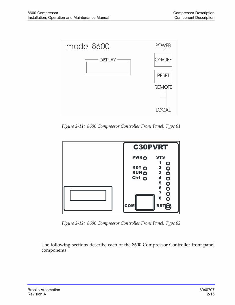
Figure 2-11: 8600 Compressor Controller Front Panel, Type 01
Figure 2-12: 8600 Compressor Controller Front Panel, Type 02
The following sections describe each of the 8600 Compressor Controller front panel components.
12345678
RSTCOM
PWR
RDY
Ch1RUN
STS
C30PVRT
Compressor Description 8600 CompressorComponent Description Installation, Operation and Maintenance Manual
8040707 Brooks Automation2-16 Revision A
ON/OFF Switch (Type 01 Only)
This switch enables you to turn the compressor and cold head on or off.
NOTE: The On/Off switch cannot be used when the LOCAL/REMOTE switch is in the REMOTE position.
Power Indicator (Type 01 Only)
The Power indicator illuminates when the ON/OFF switch is placed in the ON position. The 8600 Compressor pump is energized when the power indicator is illuminated and the elapsed time meter records system operation time.
Remote/Local Switch (Type 01 Only)
Enables you to designate if the compressor is being operated from a remote or local location. The switch must be in the REMOTE position when operating from a remote location. Conversely, the switch must be in the LOCAL position when operating the unit from the local site.
NOTE: The ON/OFF switch cannot be used when the LOCAL/REMOTE switch is in the REMOTE position.
Reset Switch (Type 01 Only)
When a failure message appears on the error message display, the light on this switch flickers.
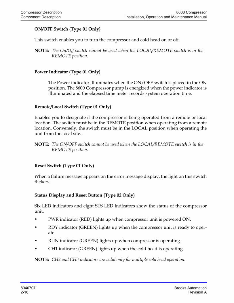
Status Display and Reset Button (Type 02 Only)
Six LED indicators and eight STS LED indicators show the status of the compressor unit.
• PWR indicator (RED) lights up when compressor unit is powered ON.
• RDY indicator (GREEN) lights up when the compressor unit is ready to oper-ate.
• RUN indicator (GREEN) lights up when compressor is operating.
• CH1 indicator (GREEN) lights up when the cold head is operating.
NOTE: CH2 and CH3 indicators are valid only for multiple cold head operation.
8600 Compressor Compressor DescriptionInstallation, Operation and Maintenance Manual Component Description
Brooks Automation 8040707Revision A 2-17
When a failure occurrs inside or outside of the compressor unit, one or more STS LED indicators light up, in an Alarm. A buzzer sounds from the compressor also. When an Alarm occurrs, check the ALARM CODE TABLE beside the STS LED indicators.
The STS LED indictors and the buzzer continue after the alarm event is finished. To clear the alarm status, push the reset button through the RST hole with a proper-sized instrument. The RDY light appears.
Controller Back Panel Components
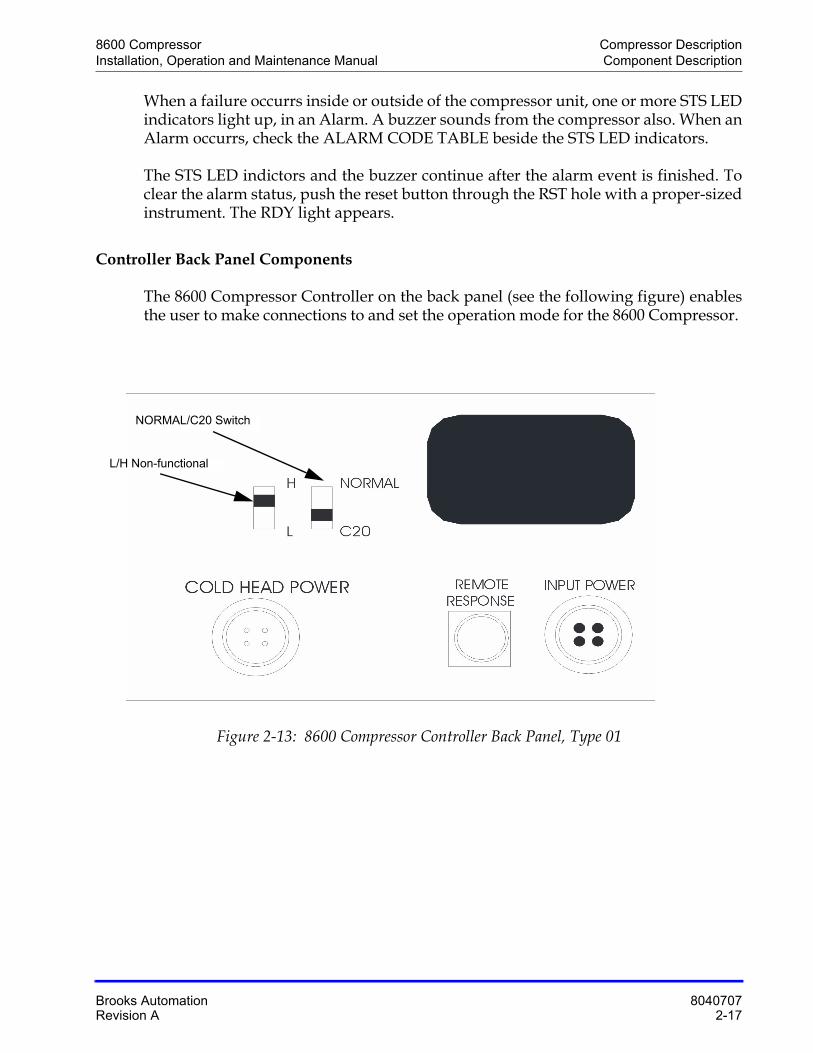
The 8600 Compressor Controller on the back panel (see the following figure) enables the user to make connections to and set the operation mode for the 8600 Compressor.
Figure 2-13: 8600 Compressor Controller Back Panel, Type 01
L/H Non-functional
NORMAL/C20 Switch
Compressor Description 8600 CompressorComponent Description Installation, Operation and Maintenance Manual
8040707 Brooks Automation2-18 Revision A
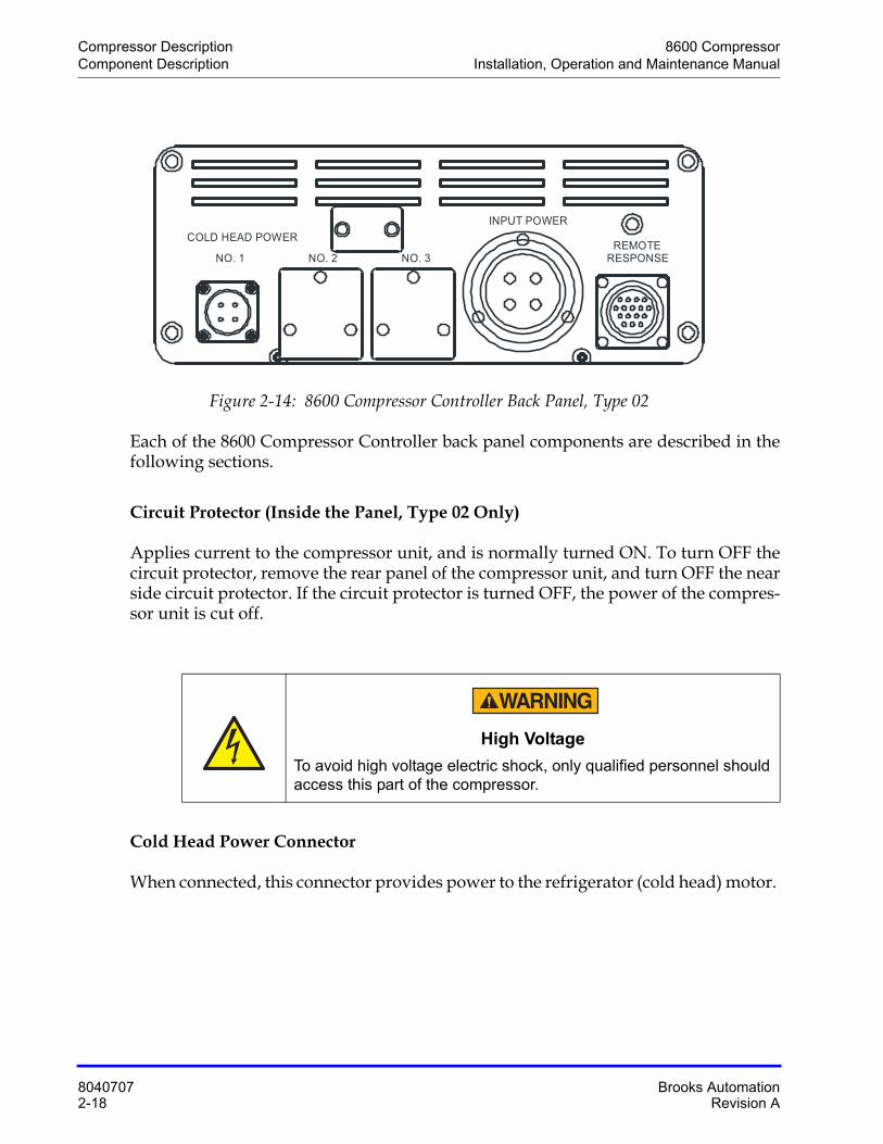
Figure 2-14: 8600 Compressor Controller Back Panel, Type 02
Each of the 8600 Compressor Controller back panel components are described in the following sections.
Circuit Protector (Inside the Panel, Type 02 Only)
Applies current to the compressor unit, and is normally turned ON. To turn OFF the circuit protector, remove the rear panel of the compressor unit, and turn OFF the near side circuit protector. If the circuit protector is turned OFF, the power of the compres-sor unit is cut off.
Cold Head Power Connector
When connected, this connector provides power to the refrigerator (cold head) motor.
High Voltage
To avoid high voltage electric shock, only qualified personnel should access this part of the compressor.
REMOTERESPONSE
INPUT POWER
NO. 3NO. 2NO. 1
COLD HEAD POWER
8600 Compressor Compressor DescriptionInstallation, Operation and Maintenance Manual Component Description
Brooks Automation 8040707Revision A 2-19
Input Power
The receptacle for connecting incoming power to the compressor. The power source can be:
• 190 - 220 VAC @ 50Hz
• 200 - 230 VAC @ 60 Hz
L/H Switch (Type 01 Only)
This switch is non-functional with this compressor model.
Normal/C20 Switch (Type 01 Only)
This switch enables you to select the input signal when you operate the 8600 Com-pressor. The switch has two settings:
• NORMAL - this is used during normal (non-remote operation).
• C20 - this is used when the Remote Response switch provides the input signal.
Remote Input-Output Connector
This switch enables you to operate the 8600 Compressor from a remote location. Refer to the remote interface wiring diagram in Figure 7-4 on page 7-18.
With Type 02, you can control the compressor and cryopump operation through the remote cable. You can also receive “answer-back” signals of the compressor and cryopump operations, and an “ALARM” signal when a failure occurs.
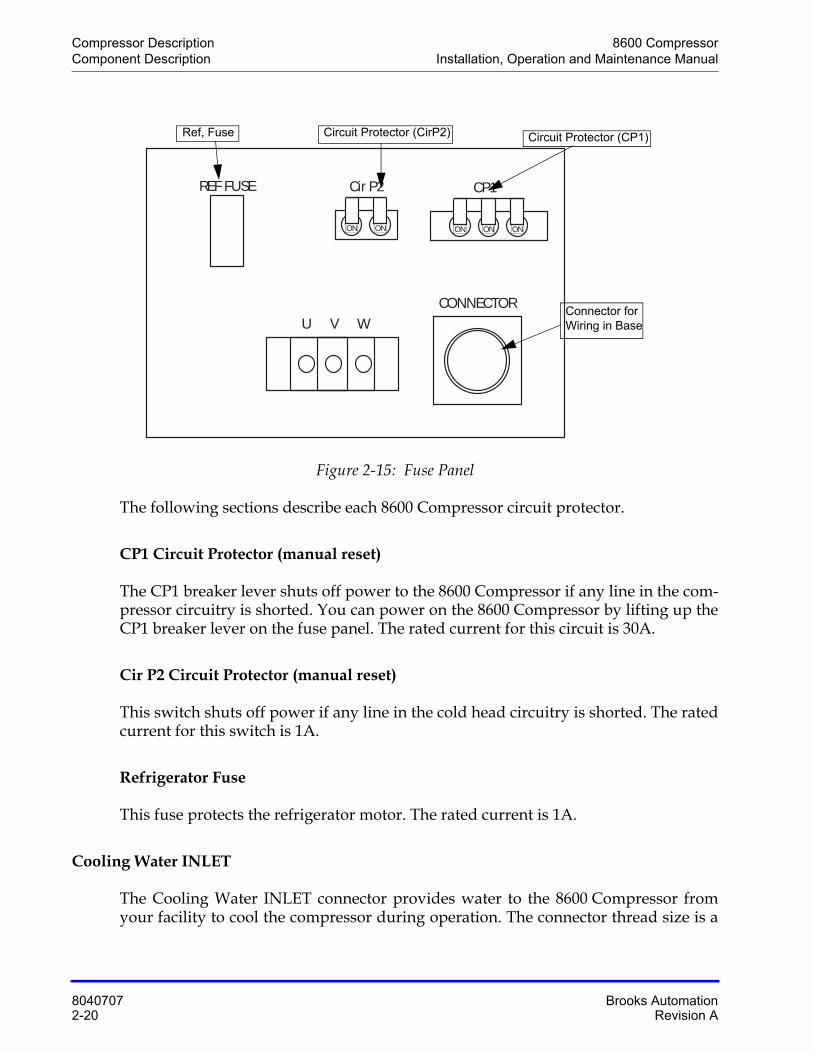
Fuse Panel, Type 01
The fuse panel (see the following figure) enables you to control the fuses associated with the 8600 Compressor.
Compressor Description 8600 CompressorComponent Description Installation, Operation and Maintenance Manual
8040707 Brooks Automation2-20 Revision A
Figure 2-15: Fuse Panel
The following sections describe each 8600 Compressor circuit protector.
CP1 Circuit Protector (manual reset)
The CP1 breaker lever shuts off power to the 8600 Compressor if any line in the com-pressor circuitry is shorted. You can power on the 8600 Compressor by lifting up the CP1 breaker lever on the fuse panel. The rated current for this circuit is 30A.
Cir P2 Circuit Protector (manual reset)
This switch shuts off power if any line in the cold head circuitry is shorted. The rated current for this switch is 1A.
Refrigerator Fuse
This fuse protects the refrigerator motor. The rated current is 1A.
Cooling Water INLET
The Cooling Water INLET connector provides water to the 8600 Compressor from your facility to cool the compressor during operation. The connector thread size is a
U V W
ON ON ON
CP1
ON ON
Cir P2
CONNECTOR
REF FUSE
Circuit Protector (CP1)Circuit Protector (CirP2)Ref, Fuse
Connector for Wiring in Base
8600 Compressor Compressor DescriptionInstallation, Operation and Maintenance Manual Component Description
Brooks Automation 8040707Revision A 2-21
3/8 in. female pipe thread. The water must meet the specifications outlined in Table 2-2 on page 2-8.
Cooling Water OUTLET
The Cooling Water OUTLET connector returns the water that has been used to cool the 8600 Compressor to your facility. The connector thread size is a 3/8 in. female pipe thread.
Cryopump Electrical Outlet
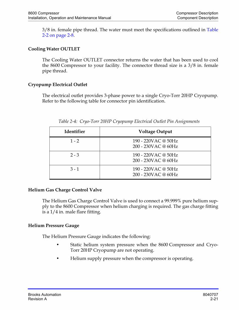
The electrical outlet provides 3-phase power to a single Cryo-Torr 20HP Cryopump. Refer to the following table for connector pin identification.
Helium Gas Charge Control Valve
The Helium Gas Charge Control Valve is used to connect a 99.999% pure helium sup-ply to the 8600 Compressor when helium charging is required. The gas charge fitting is a 1/4 in. male flare fitting.
Helium Pressure Gauge
The Helium Pressure Gauge indicates the following:
• Static helium system pressure when the 8600 Compressor and Cryo-Torr 20HP Cryopump are not operating.
• Helium supply pressure when the compressor is operating.
Table 2-4: Cryo-Torr 20HP Cryopump Electrical Outlet Pin Assignments
Identifier Voltage Output
1 - 2 190 - 220VAC @ 50Hz200 - 230VAC @ 60Hz
2 - 3 190 - 220VAC @ 50Hz200 - 230VAC @ 60Hz
3 - 1 190 - 220VAC @ 50Hz200 - 230VAC @ 60Hz
Compressor Description 8600 CompressorComponent Description Installation, Operation and Maintenance Manual
8040707 Brooks Automation2-22 Revision A
Helium Return Line Coupling
The ½-inch self-sealing Helium Return Line coupling returns the helium (which has been cycled through the Cryo-Torr 20HP Cryopump) back to the 8600 Compressor.
Helium Supply Line Coupling
The ½-inch self-sealing Helium Supply Line coupling provides a connection for high pressure compressed helium to the Cryo-Torr 20HP Cryopump cold head.
Power Connector
The Power connector is used to connect your power cable (supplied by BROOKS-Cryogenics) to the 8600 Compressor.
Alarm Status Table (Type 02 Only)
Shows the alarm codes with corresponding status indicated by an STS LED indicator. The table describes the alarm. For troubleshooting procedures, see Appendix D: Trou-bleshooting Procedures, Type 02 Only on page 7-13. If the compressor unit has no defect for the operation, all of STS LEDs are off.
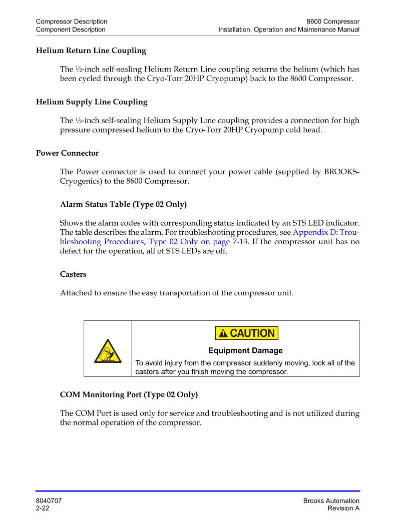
Casters
Attached to ensure the easy transportation of the compressor unit.
COM Monitoring Port (Type 02 Only)
The COM Port is used only for service and troubleshooting and is not utilized during the normal operation of the compressor.
Equipment Damage
To avoid injury from the compressor suddenly moving, lock all of the casters after you finish moving the compressor.
8600 Compressor Compressor DescriptionInstallation, Operation and Maintenance Manual Component Description
Brooks Automation 8040707Revision A 2-23
Elapsed Time Meter/Error Message Display
The Elapsed Time Meter/Error Message Display has two functions:
• Elapsed Time Meter - during normal operation, the meter records the number of hours the 8600 Compressor has been operating since being turned on for the first time.
• Error Message Display (Type 01 Only) - when an error condition occurs, this indicator shows an error message on the display. An error condition appears on the display when the RESET switch flickers (refer to Reset Switch (Type 01 Only) on page 2-16 in this subsection for more informa-tion). See 8600 Compressor Error Messages on page 7-6 for error mes-sage descriptions.
NOTE: The Elapsed Time Meter cannot be reset.

Compressor Description 8600 CompressorComponent Description Installation, Operation and Maintenance Manual
8040707 Brooks Automation2-24 Revision A
This Page Intentionally Left Blank
8600 CompressorInstallation, Operation and Maintenance Manual
Brooks Automation 8040707Revision A 3-1
3 Unpacking and Inspection
Overview
This section provides instructions for unpacking and inspecting your 8600 Compres-sor.
Chapter Contents
Shipping Carton Inspection . . . . . . . . . . . . . . . . . . . . . . . . . . . . . . . . . . . . . . . . . . . . .3-2
Compressor Inspection . . . . . . . . . . . . . . . . . . . . . . . . . . . . . . . . . . . . . . . . . . . . . . . . .3-2Compressor. . . . . . . . . . . . . . . . . . . . . . . . . . . . . . . . . . . . . . . . . . . . . . . . . . . . .3-2Static Helium System Pressure Verification. . . . . . . . . . . . . . . . . . . . . . . . . .3-2
Shipping Carton Contents . . . . . . . . . . . . . . . . . . . . . . . . . . . . . . . . . . . . . . . . . . . . . .3-3
Unpacking and Inspection 8600 CompressorShipping Carton Inspection Installation, Operation and Maintenance Manual
8040707 Brooks Automation3-2 Revision A
Shipping Carton Inspection
Inspect the exterior of the shipping carton for visible signs of damage before opening the shipping carton. Report any damage to the shipping company at once. Inspect the contents to ensure that you have received all ordered equipment. See Table 3-1 on page 3-3 for a list of the shipping contents.
Compressor Inspection
Inspect the 8600 Compressor for visible signs of damage as indicated in the following sections.
Compressor
Inspect the exterior of the 8600 Compressor for visible signs of damage and evidence of an oil leak, and check the Helium Pressure Gauge for proper helium pressure. Report any damage to the shipping company and BROOKS-Cryogenics at once.
Static Helium System Pressure Verification
Refer to the "OFF" Condition Helium System Pressure Verification on page 5-3 for more information on the static helium system pressure of the 8600 Compressor.
8600 Compressor Unpacking and InspectionInstallation, Operation and Maintenance Manual Shipping Carton Contents
Brooks Automation 8040707Revision A 3-3
Shipping Carton Contents
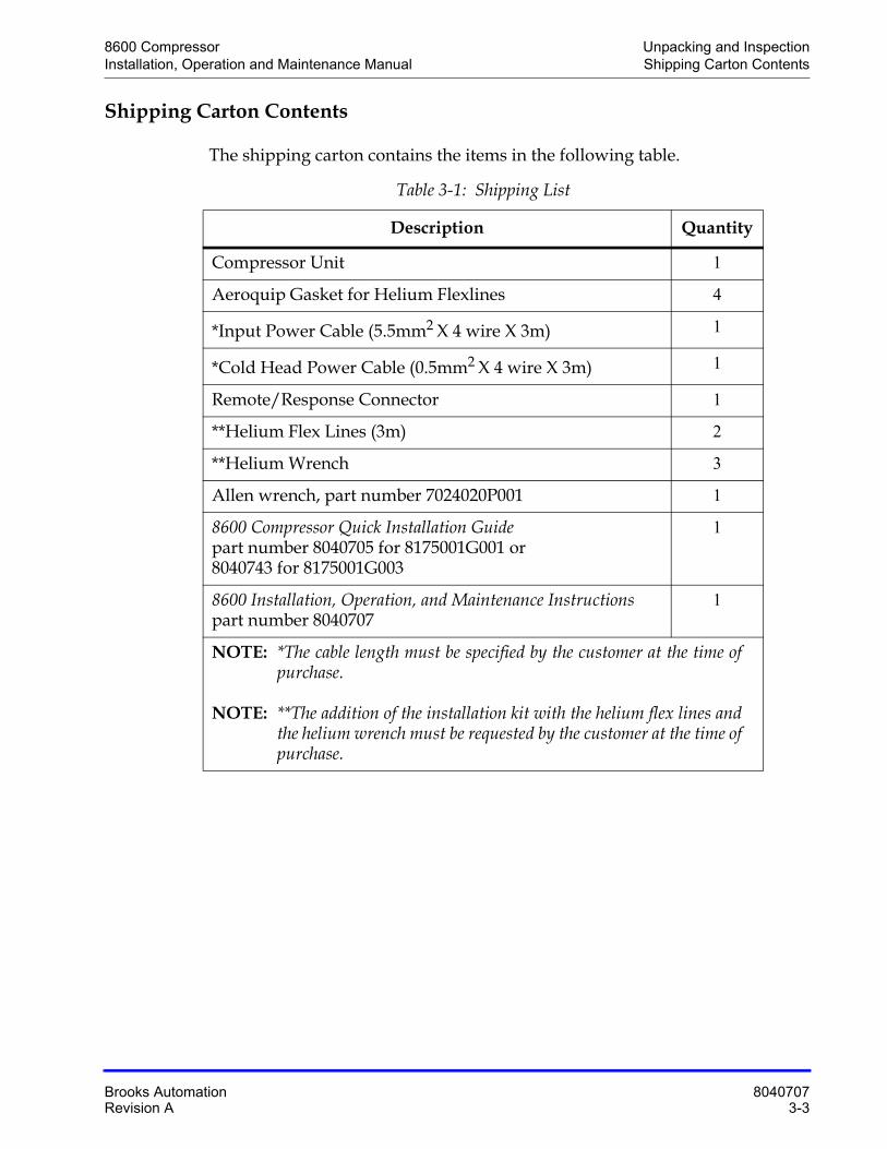
The shipping carton contains the items in the following table.
Table 3-1: Shipping List
Description Quantity
Compressor Unit 1
Aeroquip Gasket for Helium Flexlines 4
*Input Power Cable (5.5mm2 X 4 wire X 3m) 1
*Cold Head Power Cable (0.5mm2 X 4 wire X 3m) 1
Remote/Response Connector 1
**Helium Flex Lines (3m) 2
**Helium Wrench 3
Allen wrench, part number 7024020P001 1
8600 Compressor Quick Installation Guidepart number 8040705 for 8175001G001 or 8040743 for 8175001G003
1
8600 Installation, Operation, and Maintenance Instructionspart number 8040707
1
NOTE: *The cable length must be specified by the customer at the time of purchase.
NOTE: **The addition of the installation kit with the helium flex lines and the helium wrench must be requested by the customer at the time of purchase.

Unpacking and Inspection 8600 CompressorShipping Carton Contents Installation, Operation and Maintenance Manual
8040707 Brooks Automation3-4 Revision A
This Page Intentionally Left Blank
8600 CompressorInstallation, Operation and Maintenance Manual
Brooks Automation 8040707Revision A 4-1
4 Installation
Overview
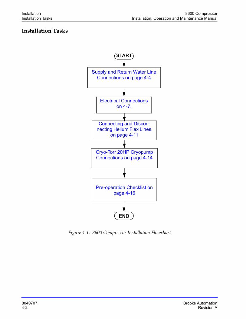
This chapter provides the installation procedures for the 8600 Compressor and con-necting it to the Cryo-Torr 20HP Cryopump. Figure 4-1 on page 4-2 highlights the major tasks for 8600 Compressor installation and refers to the appropriate installation procedures within this section.
Chapter Contents
Installation Tasks . . . . . . . . . . . . . . . . . . . . . . . . . . . . . . . . . . . . . . . . . . . . . . . . . . . . . .4-2
Environmental Specifications. . . . . . . . . . . . . . . . . . . . . . . . . . . . . . . . . . . . . . . . . . . .4-3
Supply and Return Water Line Connections . . . . . . . . . . . . . . . . . . . . . . . . . . . . . . .4-4Prerequisites to Installing Supply and Return Water Line Connections. .4-4Installing Hard Water Lines . . . . . . . . . . . . . . . . . . . . . . . . . . . . . . . . . . . . . . .4-5Installing Flexible Water Lines. . . . . . . . . . . . . . . . . . . . . . . . . . . . . . . . . . . . .4-6
Electrical Connections for Type 01 8600 Compressor . . . . . . . . . . . . . . . . . . . . . . .4-7
Connecting and Disconnecting Helium Flex Lines. . . . . . . . . . . . . . . . . . . . . . . . . .4-11Connecting Flexible Helium Lines . . . . . . . . . . . . . . . . . . . . . . . . . . . . . . . . .4-11Disconnecting Helium Flex Lines . . . . . . . . . . . . . . . . . . . . . . . . . . . . . . . . . .4-13
Cryo-Torr 20HP Cryopump Connections . . . . . . . . . . . . . . . . . . . . . . . . . . . . . . . . .4-14
Pre-operation Checklist. . . . . . . . . . . . . . . . . . . . . . . . . . . . . . . . . . . . . . . . . . . . . . . . .4-16
8600 Compressor Storage . . . . . . . . . . . . . . . . . . . . . . . . . . . . . . . . . . . . . . . . . . . . . . .4-18
Installation 8600 CompressorInstallation Tasks Installation, Operation and Maintenance Manual
8040707 Brooks Automation4-2 Revision A
Installation Tasks
Figure 4-1: 8600 Compressor Installation Flowchart
Pre-operation Checklist on page 4-16
END
Supply and Return Water Line Connections on page 4-4
Electrical Connections on 4-7.
Cryo-Torr 20HP Cryopump Connections on page 4-14
START
Connecting and Discon-necting Helium Flex Lines
on page 4-11
8600 Compressor InstallationInstallation, Operation and Maintenance Manual Environmental Specifications
Brooks Automation 8040707Revision A 4-3
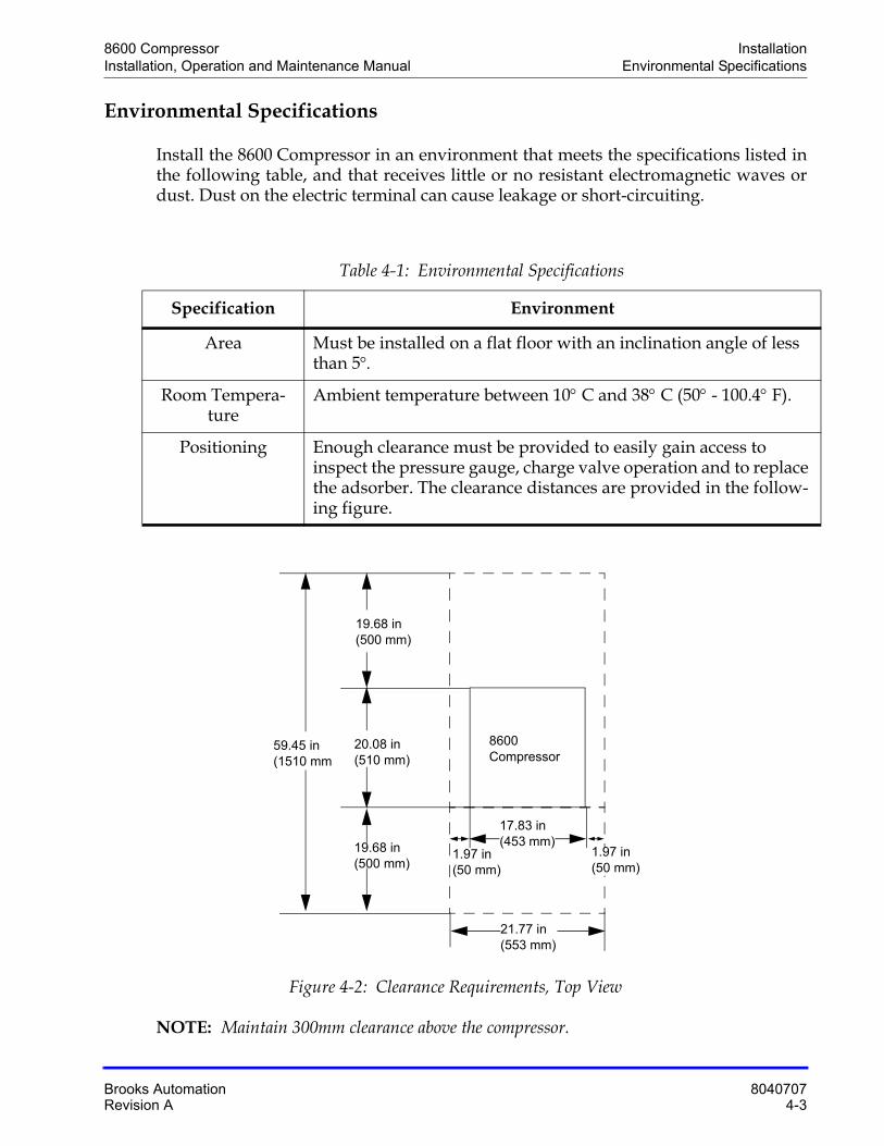
Environmental Specifications
Install the 8600 Compressor in an environment that meets the specifications listed in the following table, and that receives little or no resistant electromagnetic waves or dust. Dust on the electric terminal can cause leakage or short-circuiting.
Figure 4-2: Clearance Requirements, Top View
NOTE: Maintain 300mm clearance above the compressor.
Table 4-1: Environmental Specifications
Specification Environment
Area Must be installed on a flat floor with an inclination angle of less than 5
Room Tempera-ture
Ambient temperature between 10C and 38C (50 - 100.4 F).
Positioning Enough clearance must be provided to easily gain access to inspect the pressure gauge, charge valve operation and to replace the adsorber. The clearance distances are provided in the follow-ing figure.
59.45 in(1510 mm
19.68 in(500 mm)
20.08 in(510 mm)
19.68 in(500 mm)
1.97 in(50 mm)
1.97 in(50 mm)
21.77 in(553 mm)
17.83 in(453 mm)
8600 Compressor
Installation 8600 CompressorSupply and Return Water Line Connections Installation, Operation and Maintenance Manual
8040707 Brooks Automation4-4 Revision A
Supply and Return Water Line Connections
The following subsections describe how to install hard and flexible water lines. Before you begin, you should read and adhere to the information provided in the following section.
Prerequisites to Installing Supply and Return Water Line Connections
Brooks BROOKS-Cryogenics recommends the following prior to connecting water lines to the 8600 Compressor:
• The water used for cooling the 8600 Compressor must meet the specifi-cations outlined in Table 2-2 on page 2-8
• A water filter should be installed in the line between the cooling water main valve and the 8600 Compressor to remove water scales that can restrict the cooling water flow.
• Install a flow meter between the water filter and the 8600 Compressor for coolant observation purposes.
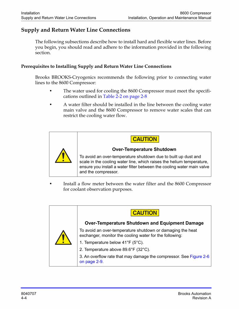
Over-Temperature Shutdown
To avoid an over-temperature shutdown due to built up dust and scale in the cooling water line, which raises the helium temperature, ensure you install a water filter between the cooling water main valve and the compressor.
Over-Temperature Shutdown and Equipment Damage
To avoid an over-temperature shutdown or damaging the heat exchanger, monitor the cooling water for the following:
1. Temperature below 41°F (5°C).
2. Temperature above 89.6°F (32°C).
3. An overflow rate that may damage the compressor. See Figure 2-6 on page 2-9.
8600 Compressor InstallationInstallation, Operation and Maintenance Manual Supply and Return Water Line Connections
Brooks Automation 8040707Revision A 4-5
NOTE: If the cooling water temperature goes below 50°F (10°C), shut down the cooling water line while the compressor is not operating. If the cooling water is at or below 50°F (10°C), and continues to flow even though the compressor is stopped, it may be difficult to start the compressor because the compressor oil becomes more vis-cous.
Drain and purge the water in the compressor when any of the following conditions occur:
• The compressor is subjected to freezing conditions.
• The compressor is not run more than one week.
• The compressor unit is shipped.
You can purge water from the compressor by opening the Cooling Water Inlet and blowing air into the compressor inlet for 30 seconds at a pressure of 30psi (0.2MPa) (gage).
Installing Hard Water Lines
The following procedure describes how to install the input and output for hard water lines. Water lines must be able to withstand pressure 1.5 times higher than the cooling water supply pressure.
1. Apply a light coating of standard plumbing thread sealant to the hard line pipe threads.
2. Install the water supply line to the Cooling Water Inlet connection on the rear panel of the 8600 Compressor.
3. Install the water return line to the Cooling Water Outlet connection on the rear panel of the 8600 Compressor.
4. Using a wrench, tighten the fittings.
5. Allow water to flow and check for leaks at the rear of the 8600 Compressor.
Equipment Damage
To avoid damaging the input and output connector threads, do not over tighten the ferrules.
Installation 8600 CompressorSupply and Return Water Line Connections Installation, Operation and Maintenance Manual
8040707 Brooks Automation4-6 Revision A
Installing Flexible Water Lines
The following procedure describes how to install the input and output for flexible water lines. Water lines must be able to withstand pressure 1.5 times higher than the cooling water supply pressure.
1. Apply a light coating of standard plumbing thread sealant to the water line fit-ting threads.
2. Install the water line fittings into the Cooling Water Inlet and Cooling Water Outlet connections on the rear panel of the 8600 Compressor.
3. Using a wrench, tighten the water line fittings.
4. Connect the Supply flexible water line to the Cooling Water Inlet water line fit-ting and secure with a hose clamp.
5. Connect the Return flexible water line to the Cooling Water Outlet water line fitting and secure with a hose clamp.
6. Allow water to flow and check for leaks at the rear of the 8600 Compressor.
Equipment Damage
To avoid damaging the input and output connector threads, do not over tighten the ferrules.
8600 Compressor InstallationInstallation, Operation and Maintenance Manual Electrical Connections for Type 01 8600 Compressor
Brooks Automation 8040707Revision A 4-7
Electrical Connections for Type 01 8600 Compressor
The input power cable is supplied with the compressor. Refer to Table 2-1 on page 2-7 for power specifications.
1. If used, connect the REMOTE/RESPONSE wiring according to Remote/Response Wiring on page 7-18.
2. Set the LOCAL/REMOTE switch to either the LOCAL or REMOTE position. See Controller Front Panel Components on page 2-14 for more information.
3. Set the NORMAL/C20 switch to the appropriate position. See Controller Back Panel Components on page 2-17 for more information.
4. Connect the compressor input power cable from the compressor to its power source.
High Voltage
To avoid high voltage electric shock, turn off all electrical power to the compressor before performing this procedure.
Installation 8600 CompressorElectrical Connections for Type 02 8600 Compressor Installation, Operation and Maintenance Manual
8040707 Brooks Automation4-8 Revision A
Electrical Connections for Type 02 8600 Compressor
The input power cable is supplied with the compressor. Refer to Table 2-1 on page 2-7 for power specifications.
1. Connect the REMOTE/RESPONSE wiring according to Wiring Procedure for Remote Connector on page 4-9.
2. Connect the compressor input power cable from the compressor to a power source. This controls the On/Off operation for the compressor.
NOTE: A high voltage transformer is available from BROOKS-Cryogenics if you use more than 208V.
High Voltage
To avoid high voltage electric shock, turn off all electrical power to the compressor before performing this procedure.
8600 Compressor InstallationInstallation, Operation and Maintenance Manual Electrical Connections for Type 02 8600 Compressor
Brooks Automation 8040707Revision A 4-9
Wiring Procedure for Remote Connector
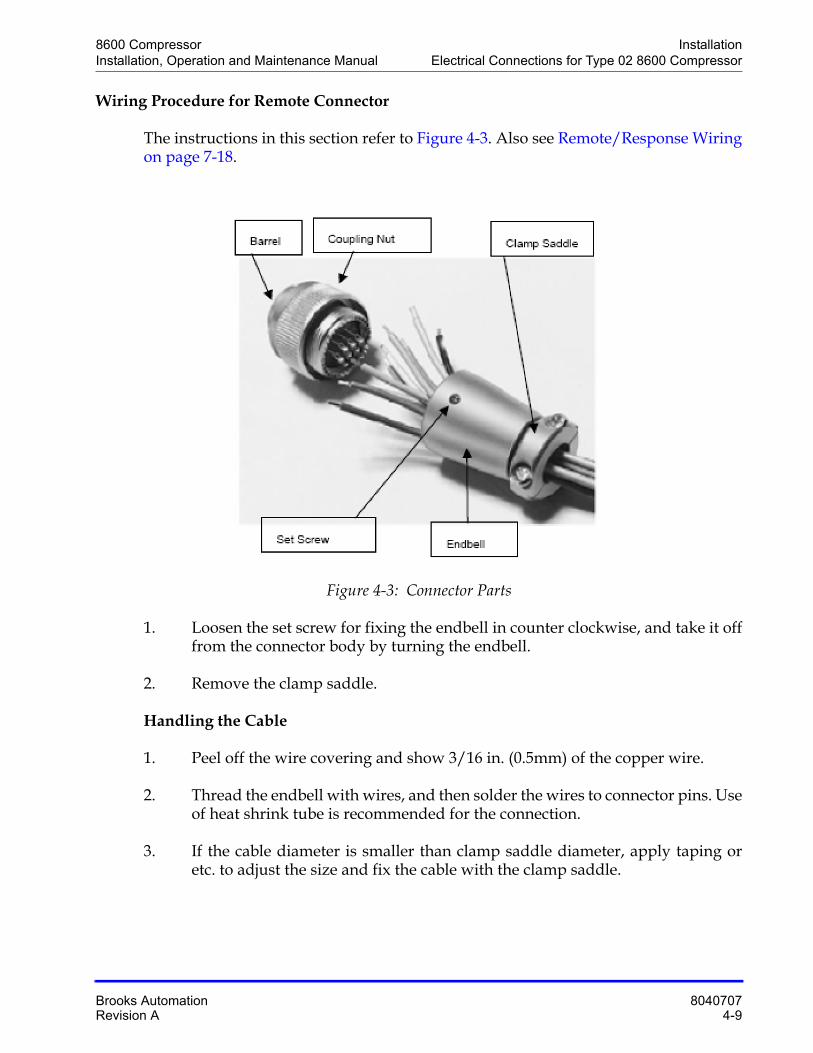
The instructions in this section refer to Figure 4-3. Also see Remote/Response Wiringon page 7-18.
Figure 4-3: Connector Parts
1. Loosen the set screw for fixing the endbell in counter clockwise, and take it off from the connector body by turning the endbell.
2. Remove the clamp saddle.
Handling the Cable
1. Peel off the wire covering and show 3/16 in. (0.5mm) of the copper wire.
2. Thread the endbell with wires, and then solder the wires to connector pins. Use of heat shrink tube is recommended for the connection.
3. If the cable diameter is smaller than clamp saddle diameter, apply taping or etc. to adjust the size and fix the cable with the clamp saddle.
Installation 8600 CompressorElectrical Connections for Type 02 8600 Compressor Installation, Operation and Maintenance Manual
8040707 Brooks Automation4-10 Revision A
Installing the Connector
1. Install the endbell to the barrel by turning it.
2. Turn the set screw in clockwise and fix the endbell.
3. Install the clamp saddle.
4. Put the identification label of the solder which is used on the connector or cable.

8600 Compressor InstallationInstallation, Operation and Maintenance Manual Connecting and Disconnecting Helium Flex Lines
Brooks Automation 8040707Revision A 4-11
Connecting and Disconnecting Helium Flex Lines
The following subsections describe how to connect and disconnect the 8600 Compressor helium flex lines. Specifications for flexible helium lines are listed in the following table.
Connecting Flexible Helium Lines
Make sure that you do the following when connecting flexible helium lines to the 8600 Compressor:
• Ensure that you read and adhere to the specifications listed in Table 4-2 before connecting the flexible helium lines.
• Always use two wrenches when connecting flexible lines.
• Do not forcibly bend the flexible helium hose. Bending the flexible hose can damage the line and cause gas leakage.
Equipment Damage
To avoid damaging o-rings and creating a helium leak, follow the procedure in this section, including Figure 4-4 on page 4-12.
Table 4-2: Flexible Helium Supply and Return Lines
Specification Value
Length Flexible Supply Line Customer Specific
Length Flexible Return Line Customer Specific
Gas Helium gas (Purity more than 99.999%)
Pressure Maximum 360psi (2.45MPa) (gage)
Maximum Temperature 104ºF (40ºC)
Material SUS304
Connection 1/2B Self-sealing coupling
Installation 8600 CompressorConnecting and Disconnecting Helium Flex Lines Installation, Operation and Maintenance Manual
8040707 Brooks Automation4-12 Revision A
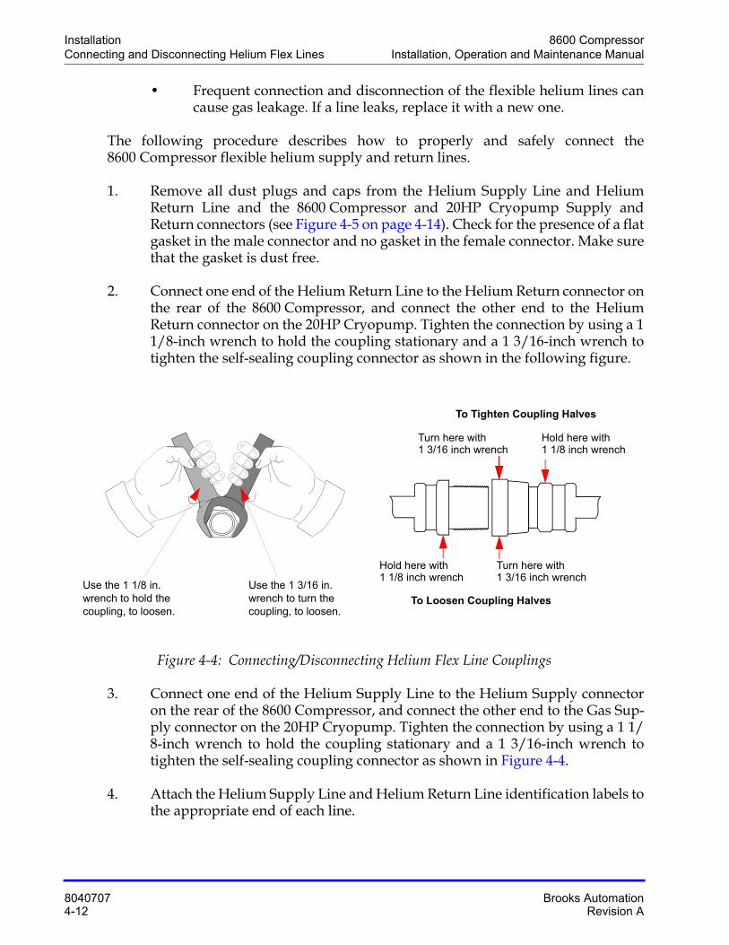
• Frequent connection and disconnection of the flexible helium lines can cause gas leakage. If a line leaks, replace it with a new one.
The following procedure describes how to properly and safely connect the 8600 Compressor flexible helium supply and return lines.
1. Remove all dust plugs and caps from the Helium Supply Line and Helium Return Line and the 8600 Compressor and 20HP Cryopump Supply and Return connectors (see Figure 4-5 on page 4-14). Check for the presence of a flat gasket in the male connector and no gasket in the female connector. Make sure that the gasket is dust free.
2. Connect one end of the Helium Return Line to the Helium Return connector on the rear of the 8600 Compressor, and connect the other end to the Helium Return connector on the 20HP Cryopump. Tighten the connection by using a 1 1/8-inch wrench to hold the coupling stationary and a 1 3/16-inch wrench to tighten the self-sealing coupling connector as shown in the following figure.
Figure 4-4: Connecting/Disconnecting Helium Flex Line Couplings
3. Connect one end of the Helium Supply Line to the Helium Supply connector on the rear of the 8600 Compressor, and connect the other end to the Gas Sup-ply connector on the 20HP Cryopump. Tighten the connection by using a 1 1/8-inch wrench to hold the coupling stationary and a 1 3/16-inch wrench to tighten the self-sealing coupling connector as shown in Figure 4-4.
4. Attach the Helium Supply Line and Helium Return Line identification labels to the appropriate end of each line.
Use the 1 3/16 in. wrench to turn the coupling, to loosen.
Use the 1 1/8 in. wrench to hold the coupling, to loosen.
To Tighten Coupling Halves
Hold here withTurn here with
To Loosen Coupling Halves
1 3/16 inch wrench 1 1/8 inch wrench
Turn here with 1 3/16 inch wrench
Hold here with1 1/8 inch wrench
8600 Compressor InstallationInstallation, Operation and Maintenance Manual Connecting and Disconnecting Helium Flex Lines
Brooks Automation 8040707Revision A 4-13
5. Ensure that the helium gas pressure gauge reads 1.4 ± 0.04MPa (gage) at 20°C. If the indicated pressure is higher than the specified value, allow a slight amount of helium gas to discharge by opening the gas charge valve very slowly. If the indicated pressure is lower than the specified value, add helium gas as described in Increasing Helium Pressure on page 6-9.
Disconnecting Helium Flex Lines
The following procedure describes how to properly and safely disconnect the 8600 Compressor helium flex lines.
1. Shut down the 8600 Compressor.
2. Wait until the 20HP Cryopump is warmed up to room temperature prior to disconnecting the flexible lines from the Helium Return and Helium Supply connectors at the rear of the 8600 Compressor. However, if you are performing a helium circuit decontamination procedure, immediately disconnect the flexi-ble lines from the Helium Return and Helium Supply connectors when the pump is cold.
3. Disconnect the two self-sealing coupling connectors quickly to minimize helium leakage by using a 1 1/8-inch wrench to hold the coupling stationary, and use a 1 3/16-inch wrench to loosen the self-sealing coupling connector as shown in Figure 4-4 on page 4-12.
Installation 8600 CompressorCryo-Torr 20HP Cryopump Connections Installation, Operation and Maintenance Manual
8040707 Brooks Automation4-14 Revision A
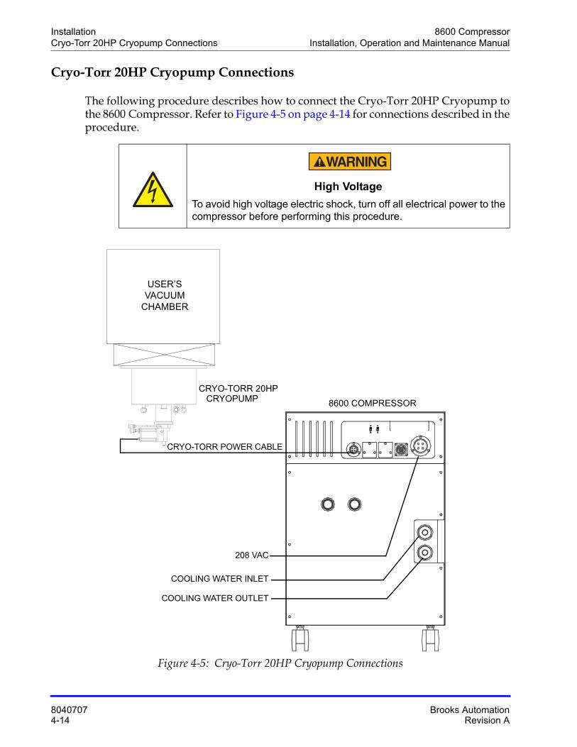
Cryo-Torr 20HP Cryopump Connections
The following procedure describes how to connect the Cryo-Torr 20HP Cryopump to the 8600 Compressor. Refer to Figure 4-5 on page 4-14 for connections described in the procedure.
Figure 4-5: Cryo-Torr 20HP Cryopump Connections
High Voltage
To avoid high voltage electric shock, turn off all electrical power to the compressor before performing this procedure.
USER’SVACUUM
CHAMBER
CRYO-TORR POWER CABLE
8600 COMPRESSOR
CRYO-TORR 20HP CRYOPUMP
208 VAC
COOLING WATER INLET
COOLING WATER OUTLET
8600 Compressor InstallationInstallation, Operation and Maintenance Manual Cryo-Torr 20HP Cryopump Connections
Brooks Automation 8040707Revision A 4-15
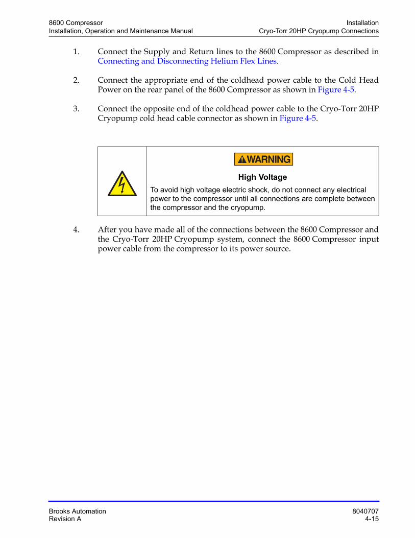
1. Connect the Supply and Return lines to the 8600 Compressor as described in Connecting and Disconnecting Helium Flex Lines.
2. Connect the appropriate end of the coldhead power cable to the Cold Head Power on the rear panel of the 8600 Compressor as shown in Figure 4-5.
3. Connect the opposite end of the coldhead power cable to the Cryo-Torr 20HP Cryopump cold head cable connector as shown in Figure 4-5.
4. After you have made all of the connections between the 8600 Compressor and the Cryo-Torr 20HP Cryopump system, connect the 8600 Compressor input power cable from the compressor to its power source.
High Voltage
To avoid high voltage electric shock, do not connect any electrical power to the compressor until all connections are complete between the compressor and the cryopump.
Installation 8600 CompressorPre-operation Checklist Installation, Operation and Maintenance Manual
8040707 Brooks Automation4-16 Revision A
Pre-operation Checklist
NOTE: See Adjusting System Helium Pressure on page 6-6 to add or remove helium from the compressor.
The following procedure describes how to set up the 8600 Compressor prior to oper-ation:
1. Make sure that the input power requirements are within the specified values shown in the specification tables in Table 2-1 on page 2-7.
2. The POWER LAMP should illuminate when the power is supplied to the 8600 Compressor.
3. The LOCAL/REMOTE switch should be in the appropriate setting for Type 01.See Controller Front Panel Components on page 2-14.
4. The NORMAL/C20 switch should be in the appropriate setting for Type 01. See Controller Back Panel Components on page 2-17 for more information.
5. All connections to the 8600 Compressor should be made, including electrical, water, remote and cryopump connections.
6. Cooling water requirements should be within the specified parameters shown in Table 2-3 on page 2-10.
7. Helium gas static pressure requirements should be within the specified param-eters shown in Table 2-3 on page 2-10.
The compressor pressure reading will decrease from the normal system operating pressure during cryopump regeneration or if fewer cryopumps are being operated. These are normal variations in the compressor pressure reading and should not be cause for concern.
Equipment Damage
To avoid damaging the compressor, ensure the helium pressure is not in the red zone of the gauge (too little pressure), or above 260 psig (too much pressure).
8600 Compressor InstallationInstallation, Operation and Maintenance Manual Pre-operation Checklist
Brooks Automation 8040707Revision A 4-17
If you have concerns about system performance changing, then check the normal sys-tem operating pressure which was determined in Compressor Operation on page 5-4. If the normal system operating pressure is not correct, check the system for leaks.
After the leaks have been repaired, add helium to return the system to normal operat-ing system pressure as described in Adjusting System Helium Pressure on page 6-6.
NOTE: To ensure the helium pressure is correct, see Table 2-3 on page 2-10. See Adjusting System Helium Pressure on page 6-6 to add or remove helium from the compressor.
After you have verified the final checklist (the previous steps), you are ready to oper-ate the 8600 Compressor and refrigerator.
Equipment Damage
To avoid damaging the compressor after startup, ensure the helium pressure is not in the red zone of the gauge (too little pressure), or above 260 psig (too much pressure).
Installation 8600 Compressor8600 Compressor Storage Installation, Operation and Maintenance Manual
8040707 Brooks Automation4-18 Revision A
8600 Compressor Storage
If the 8600 Compressor must be stored, do the following:
1. Disconnect the flexible lines, cables and water piping. Purge the compressor of water.
2. Install the protective caps on the helium gas connectors. Cover the compressor with a vinyl sheet as it was during shipment.
3. Keep the 8600 Compressor away from sunlight, high temperatures, high humidity, vibration, radiation, rain, wind and dust.
4. Store the 8600 Compressor on a flat surface with an inclination angle of less than 5 degrees.
5. Periodically check the helium gas pressure. If the indicated pressure falls and remains below the minimum static pressure, call the BROOKS-Cryogenics Customer Support center.
NOTE: If the 8600 Compressor is not used for three or more months, operate the compres-sor at least once during that time.
Equipment Damage
To avoid damaging the compressor while shipping, package the compressor the same way in which it was originally shipped.
8600 CompressorInstallation, Operation and Maintenance Manual
Brooks Automation 8040707Revision A 5-1
5 Operation
Overview
This chapter provides the operation procedures for the 8600 Compressor.
Chapter Contents
Adjusting System Helium Pressure . . . . . . . . . . . . . . . . . . . . . . . . . . . . . . . . . . . . . .5-2
"OFF" Condition Helium System Pressure Verification. . . . . . . . . . . . . . . . . . . . . .5-3
Compressor Operation . . . . . . . . . . . . . . . . . . . . . . . . . . . . . . . . . . . . . . . . . . . . . . . . .5-4Turn On the Type 01 Compressor . . . . . . . . . . . . . . . . . . . . . . . . . . . . . . . . . .5-5Turn On the Type 02 Compressor (Use Local Mode). . . . . . . . . . . . . . . . . .5-5Turn Off the Type 02 Compressor. . . . . . . . . . . . . . . . . . . . . . . . . . . . . . . . . .5-6Return the Type 02 Compressor to Remote Mode . . . . . . . . . . . . . . . . . . . .5-6Document Compressor Performance . . . . . . . . . . . . . . . . . . . . . . . . . . . . . . .5-6
Secondary Power: CP1 Breaker and Troubleshooting Diagnostic Problems . . . .5-8
Replacement of Helium Circuit Components . . . . . . . . . . . . . . . . . . . . . . . . . . . . . .5-9
Operation 8600 CompressorAdjusting System Helium Pressure Installation, Operation and Maintenance Manual
8040707 Brooks Automation5-2 Revision A
Adjusting System Helium Pressure
Your BROOKS-Cryogenics high vacuum pump system is comprised of several pres-surized components, such as a compressor, flex lines, and cryopumps. Each compo-nent is charged with helium before shipment. After all cryopumps, helium lines, and manifolds are attached to the compressor, the system ("OFF" Condition) helium charge pressure must be verified before system operation. After the ("OFF" Condition) helium system pressure has been verified, the system is ready for operation. After cool down, the normal system operating pressure is recorded.
NOTE: The 8600 Compressor is designed for continuous operation and should remain ON even when the cryopumps are in regeneration.
8600 Compressor OperationInstallation, Operation and Maintenance Manual "OFF" Condition Helium System Pressure Verification
Brooks Automation 8040707Revision A 5-3
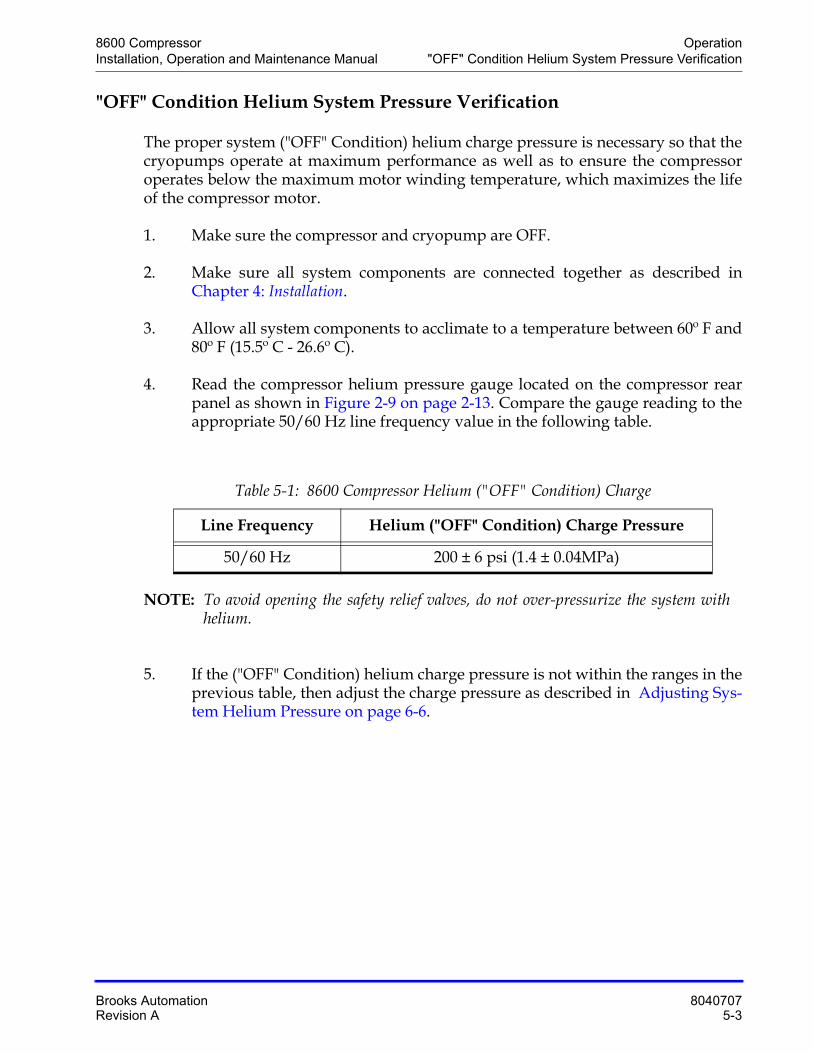
"OFF" Condition Helium System Pressure Verification
The proper system ("OFF" Condition) helium charge pressure is necessary so that the cryopumps operate at maximum performance as well as to ensure the compressor operates below the maximum motor winding temperature, which maximizes the life of the compressor motor.
1. Make sure the compressor and cryopump are OFF.
2. Make sure all system components are connected together as described in Chapter 4: Installation.
3. Allow all system components to acclimate to a temperature between 60º F and 80º F (15.5º C - 26.6º C).
4. Read the compressor helium pressure gauge located on the compressor rear panel as shown in Figure 2-9 on page 2-13. Compare the gauge reading to the appropriate 50/60 Hz line frequency value in the following table.
NOTE: To avoid opening the safety relief valves, do not over-pressurize the system with helium.
5. If the ("OFF" Condition) helium charge pressure is not within the ranges in the previous table, then adjust the charge pressure as described in Adjusting Sys-tem Helium Pressure on page 6-6.
Table 5-1: 8600 Compressor Helium ("OFF" Condition) Charge
Line Frequency Helium ("OFF" Condition) Charge Pressure
50/60 Hz 200 ± 6 psi (1.4 ± 0.04MPa)
Operation 8600 CompressorCompressor Operation Installation, Operation and Maintenance Manual
8040707 Brooks Automation5-4 Revision A
Compressor Operation
Before using the compressor, do the following:
1. Check the input power requirements, as specified in Specifications on page 2-4.
2. Set the LOCAL/REMOTE switch for Type 01 8600 Compressors. See Control-ler Front Panel Components on page 2-14 for more information.
3. Set the NORMAL/C20 switch for Type 01 8600 Compressors. See Controller Front Panel Components on page 2-14 for more information.
4. Check all electrical, water, remote and cryopump connections to the 8600 Compressor.
5. Check cooling water requirements, as specified in Table 2-2 on page 2-8.
6. Check helium gas static pressure requirements, as specified in Table 2-3 on page 2-10.
7. Check the POWER LAMP (PWR LED) illuminates when the power is supplied to the 8600 Compressor.
NOTE: To ensure the helium pressure is correct, see Table 2-3 on page 2-10. To add or remove helium from the compressor, see Adjusting System Helium Pres-sure on page 6-6.
Equipment Damage
To avoid damaging the compressor after it starts, ensure the helium pressure is not in the red zone of the gauge (too little pressure), or above 260 psig (too much pressure).
8600 Compressor OperationInstallation, Operation and Maintenance Manual Compressor Operation
Brooks Automation 8040707Revision A 5-5
Turn On the Type 01 Compressor
The following procedure describes how to turn on the 8600 Compressor, Type 01:
1. Press the ON/OFF key on the front control panel (for Type 01) to turn on the 8600 Compressor, and to start cryopump operation.
2. After the second stage temperature for the cryopumps is below 17K, record the compressor pressure gauge reading as the normal system operating pressure.
Turn On the Type 02 Compressor (Use Local Mode)
The following procedure describes how to turn on the 8600 Compressor, Type 02:
1. Ensure the power is connected to the compressor to turn it on and start cryopump operation.
2. Use the allen wrench provided with the compressor (part number 7024020P001) to press the RST switch.
The indicator lights cycle from STS 1 through STS 8 continuously.
3. When the STS 4 indicator lights, press the RST switch.
This switches the compressor to Local mode. You can now control it manually.
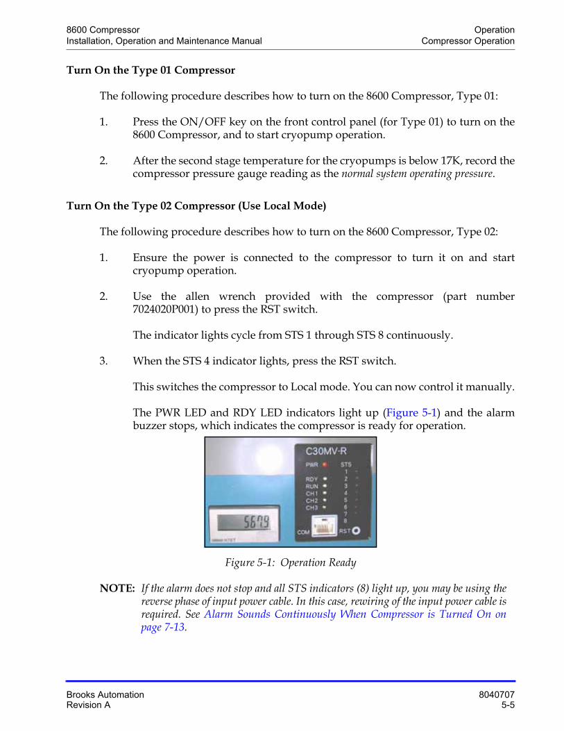
The PWR LED and RDY LED indicators light up (Figure 5-1) and the alarm buzzer stops, which indicates the compressor is ready for operation.
Figure 5-1: Operation Ready
NOTE: If the alarm does not stop and all STS indicators (8) light up, you may be using the reverse phase of input power cable. In this case, rewiring of the input power cable is required. See Alarm Sounds Continuously When Compressor is Turned On on page 7-13.
Operation 8600 CompressorCompressor Operation Installation, Operation and Maintenance Manual
8040707 Brooks Automation5-6 Revision A
4. After the second stage temperature for the cryopumps is below 17K, record the compressor pressure gauge reading as the normal system operating pressure.
Turn Off the Type 02 Compressor
The following procedure describes how to turn off the 8600 Compressor, Type 02:
1. Ensure the compressor is in Local mode by following the instructions in the previous section.
2. Use the allen wrench provided with the compressor (part number 7024020P001) to press the RST switch.
The indicator lights cycle from STS 1 through STS 8 continuously.
3. When the STS 4 indicator lights, press the RST switch.
The compressor stops.
Turn the compressor on, follow the instruction in the previous section.
Return the Type 02 Compressor to Remote Mode
The following procedure describes how to return the 8600 Compressor, Type 02 to Remote mode so that a computer or other source can operate the compressor:
1. Ensure the compressor is in local mode by following the instructions in Turn On the Type 02 Compressor (Use Local Mode) on page 5-5.
2. Use the allen wrench provided with the compressor (part number 7024020P001) to press the RST switch.
The indicator lights cycle from STS 1 through STS 8 continuously.
3. When the STS 8 indicator lights, press the RST switch.
The compressor switches to Remote mode. The controlling source may turn on the compressor or shut it off, as designated.
Document Compressor Performance
Attach a copy of the data next to the compressor gauge on each compressor. Verify this data for each tool installation, and whenever you make a configuration change that affects the system helium gas and line volume.
8600 Compressor OperationInstallation, Operation and Maintenance Manual Compressor Operation
Brooks Automation 8040707Revision A 5-7
The compressor pressure reading decreases from the normal system operating pres-sure during cryopump regeneration, or if you operate fewer cryopumps. These are normal variations in the compressor pressure.
If you have concerns about system performance changing, then check the normal sys-tem operating pressure, which was determined in Compressor Operation on page 5-4 within this section.
Generally the pressure should be less than or equal to 2.1MPa (gage), but the length of the flexible hose changes requirements. A hose longer than 3m raises the operating pressure. If the normal system operating pressure is not correct, check the system for leaks.
After the leaks have been repaired, helium must be added to return the system to nor-mal operating system pressure as described in Chapter 6: Maintenance.
Operation 8600 CompressorSecondary Power: CP1 Breaker and Troubleshooting Diagnostic Problems Installation, Operation and Mainte-
8040707 Brooks Automation5-8 Revision A
Secondary Power: CP1 Breaker and Troubleshooting Diagnostic Problems
NOTE: This applies to Type 01 only.
Observe the following precautions when powering up the 8600 Compressor.
• You can power on the 8600 Compressor by lifting up the (CP1) breaker lever on the fuse panel. DO NOT switch the breaker lever to OFF immediately after turning on the compressor. If you switch the compressor off too soon, the diag-nostic tests will fail, the LCD digits on the Error Display will display a series of black dots, and the alarm will sound continuously. (The LCD displays the elapsed time without an alarm sound after a successful startup.)
• The compressor startup diagnostics also fails if the following conditions occur:
• The backup battery has no power.
• The power is unstable one second after the compressor has been started.
If you encounter the following diagnostic failures, do the following:
1. If the compressor diagnostics fail and the alarm sounds within two minutes after power-up, turn the power off for five minutes before restarting the com-pressor.
2. If the compressor diagnostics fail and the alarm sounds ten or more minutes after power-up, turn the power off for over one hour before restarting the com-pressor.
8600 Compressor OperationInstallation, Operation and Maintenance Manual Replacement of Helium Circuit Components
Brooks Automation 8040707Revision A 5-9
Replacement of Helium Circuit Components
On occasion, it may be necessary to replace components such as the cryopump, helium gas lines or compressors, or change the configuration of the system. Whenever any of these conditions occur, perform the procedure described in "OFF" Condition Helium System Pressure Verification on page 5-3 to ensure that static helium system pressure has not changed.
NOTE: If you use the 8600 Compressor on the same manifold as other BROOKS-Cryogen-ics compressors, reduce the helium charge pressure to 200 - 210 psig. This prevents the helium safety valves from opening.

Operation 8600 CompressorReplacement of Helium Circuit Components Installation, Operation and Maintenance Manual
8040707 Brooks Automation5-10 Revision A
This Page Intentionally Left Blank
8600 CompressorInstallation, Operation and Maintenance Manual
Brooks Automation 8040707Revision A 6-1
6 Maintenance
Overview
This chapter explains the regularly scheduled maintenance recommended for 8600 Compressors.
Chapter Contents
Scheduled Maintenance . . . . . . . . . . . . . . . . . . . . . . . . . . . . . . . . . . . . . . . . . . . . . . . .6-2Suggested Maintenance Equipment . . . . . . . . . . . . . . . . . . . . . . . . . . . . . . . .6-2Adsorber Replacement . . . . . . . . . . . . . . . . . . . . . . . . . . . . . . . . . . . . . . . . . . .6-2
Adjusting System Helium Pressure . . . . . . . . . . . . . . . . . . . . . . . . . . . . . . . . . . . . . .6-6Reducing Helium Pressure. . . . . . . . . . . . . . . . . . . . . . . . . . . . . . . . . . . . . . . .6-8Increasing Helium Pressure . . . . . . . . . . . . . . . . . . . . . . . . . . . . . . . . . . . . . . .6-9
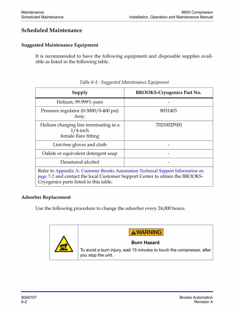
Maintenance 8600 CompressorScheduled Maintenance Installation, Operation and Maintenance Manual
8040707 Brooks Automation6-2 Revision A
Scheduled Maintenance
Suggested Maintenance Equipment
It is recommended to have the following equipment and disposable supplies avail-able as listed in the following table.
Adsorber Replacement
Use the following procedure to change the adsorber every 24,000 hours.
Table 6-1: Suggested Maintenance Equipment
Supply BROOKS-Cryogenics Part No.
Helium, 99.999% pure -
Pressure regulator (0-3000/0-400 psi) Assy.
8031403
Helium charging line terminating in a 1/4-inch
female flare fitting
7021002P001
Lint-free gloves and cloth -
Oakite or equivalent detergent soap -
Denatured alcohol -
Refer to Appendix A: Customer Brooks Automation Technical Support Information on page 7-2 and contact the local Customer Support Center to obtain the BROOKS-Cryogenics parts listed in this table.
Burn Hazard
To avoid a burn injury, wait 15 minutes to touch the compressor, after you stop the unit.
8600 Compressor MaintenanceInstallation, Operation and Maintenance Manual Scheduled Maintenance
Brooks Automation 8040707Revision A 6-3
NOTE: To ensure the helium pressure is correct, see Table 2-3 on page 2-10.
1. Close the Cryo gate valve of the high vacuum system and warm the cryopump to room temperature.
2. Shut off power to the compressor by turning off the breaker cabinet panel and locking the breaker in the off position (lock-out and tag-out).
3. Disconnect the flexible lines from the Helium Return and Helium Supply con-nectors at the rear of the 8600 Compressor.
4. Using an open-ended wrench, remove the two rear panel jam nuts.
5. Using a Phillips screwdriver, remove the 7 screws that secure the rear panel to the 8600 Compressor.
6. Disconnect the flexible line from the adsorber inlet by using a 1 3/16 in. wrench to turn the self-sealing coupling while using a 1 1/8 in. wrench to hold the cou-pling stationary, as shown in the following figure. Disconnect the two self-seal-ing coupling connectors quickly to minimize helium leakage.
Equipment Damage
To avoid damaging the compressor, ensure the helium pressure is not in the red zone of the gauge (too little pressure), or above 260 psig (too much pressure).
High Pressure Gas
To avoid an explosion and severe injury, vent the gas in the adsorber before you dispose of it.
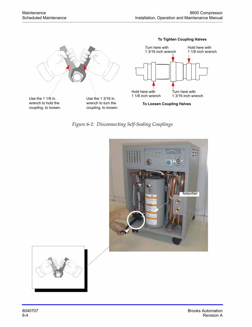
Maintenance 8600 CompressorScheduled Maintenance Installation, Operation and Maintenance Manual
8040707 Brooks Automation6-4 Revision A
Figure 6-1: Disconnecting Self-Sealing Couplings
Use the 1 3/16 in. wrench to turn the coupling, to loosen.
Use the 1 1/8 in. wrench to hold the coupling, to loosen.
To Tighten Coupling Halves
Hold here withTurn here with
To Loosen Coupling Halves
1 3/16 inch wrench 1 1/8 inch wrench
Turn here with 1 3/16 inch wrench
Hold here with1 1/8 inch wrench
Adsorber
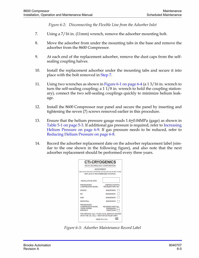
8600 Compressor MaintenanceInstallation, Operation and Maintenance Manual Scheduled Maintenance
Brooks Automation 8040707Revision A 6-5
Figure 6-2: Disconnecting the Flexible Line from the Adsorber Inlet
7. Using a 7/16 in. (11mm) wrench, remove the adsorber mounting bolt.
8. Move the adsorber from under the mounting tabs in the base and remove the adsorber from the 8600 Compressor.
9. At each end of the replacement adsorber, remove the dust caps from the self-sealing coupling halves.
10. Install the replacement adsorber under the mounting tabs and secure it into place with the bolt removed in Step 7.
11. Using two wrenches as shown in Figure 6-1 on page 6-4 (a 1 3/16 in. wrench to turn the self-sealing coupling; a 1 1/8 in. wrench to hold the coupling station-ary), connect the two self-sealing couplings quickly to minimize helium leak-age.
12. Install the 8600 Compressor rear panel and secure the panel by inserting and tightening the seven (7) screws removed earlier in this procedure.
13. Ensure that the helium pressure gauge reads 1.4+0.04MPa (gage) as shown in Table 5-1 on page 5-3. If additional gas pressure is required, refer to Increasing Helium Pressure on page 6-9. If gas pressure needs to be reduced, refer to Reducing Helium Pressure on page 6-8.
14. Record the adsorber replacement date on the adsorber replacement label (sim-ilar to the one shown in the following figure), and also note that the next adsorber replacement should be performed every three years.
Figure 6-3: Adsorber Maintenance Record Label
HELIX TECHNOLOGY CORPORATION
CTI-CRYOGENICS
ADSORBER(HELIUM FILTRATION CARTRIDGE GE-HELIUM GAS 99.999% PURE)
REPLACE AT RECOMMENDED INTERVAL
INSTALLATION DATE
PRESSURIZED 265PSIG(1827KPa)
8200/SC
MC 8300
9600/9700a
PRESSURIZEDCOMPRESSOR MODEL 1020R/1020RW S080260K0018500/8510
FOR SERVICE CALL YOUR LOCAL SERVICE CENTEROR IN THE US, CALL 1-800-FOR-GUTS(367-4887)
MADE IN U.S.A.
COMPRESSOR MODEL REORDER PART NO.
8080255K001
8080265K001
8080280K001
8080300K001
REORDER PART NO.
S080275K001
CE
Maintenance 8600 CompressorAdjusting System Helium Pressure Installation, Operation and Maintenance Manual
8040707 Brooks Automation6-6 Revision A
Adjusting System Helium Pressure
The procedures in the following subsections describe how to adjust (increase or decrease) the system helium pressure.
NOTE: The procedures in the following subsections can be performed on an 8600 Compressor that has its ON/OFF switch in either the ON or OFF position. The helium pressure gauge should be set to:
• Static helium system pressure if the 8600 Compressor is turned OFF. Refer to "OFF" Condition Helium System Pressure Verification on page 5-3 for more information
• Normal system operating pressure if the compressor is turned ON. Refer to Compressor Operation on page 5-4 for more information.
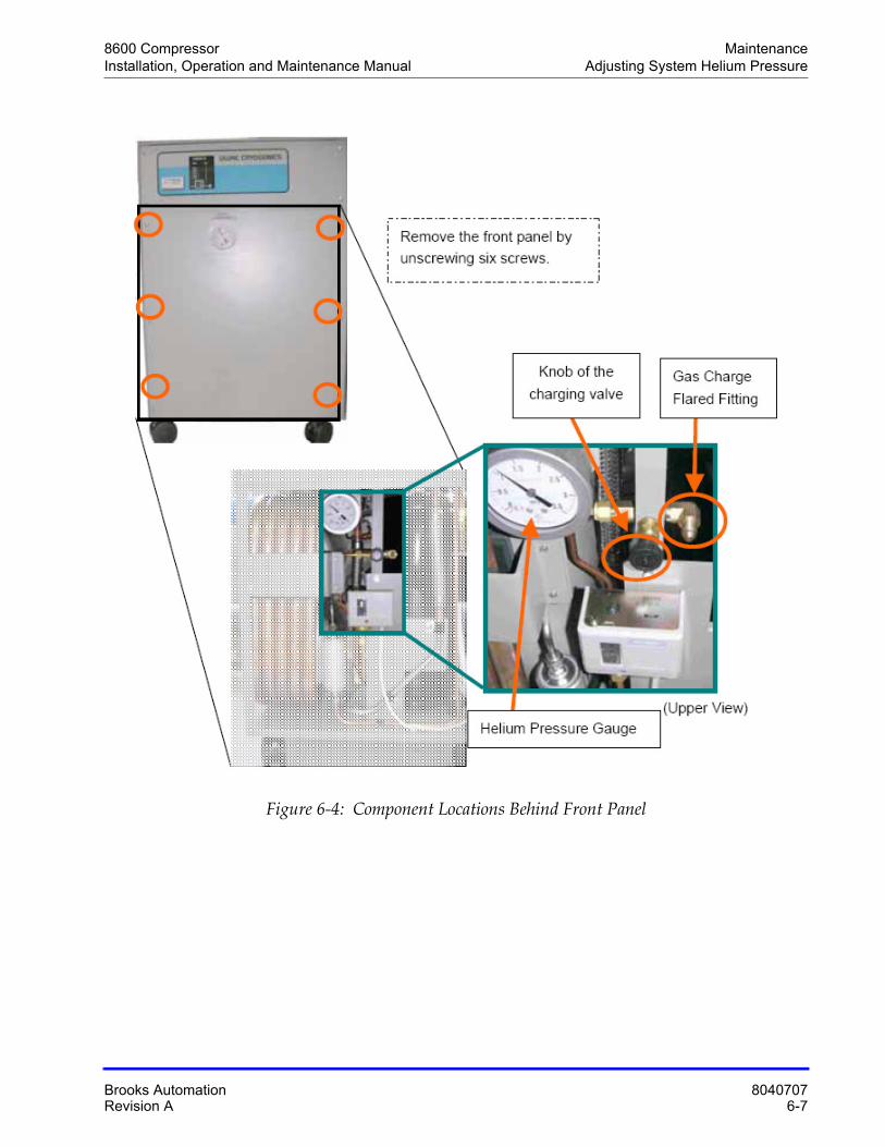
8600 Compressor MaintenanceInstallation, Operation and Maintenance Manual Adjusting System Helium Pressure
Brooks Automation 8040707Revision A 6-7
Figure 6-4: Component Locations Behind Front Panel
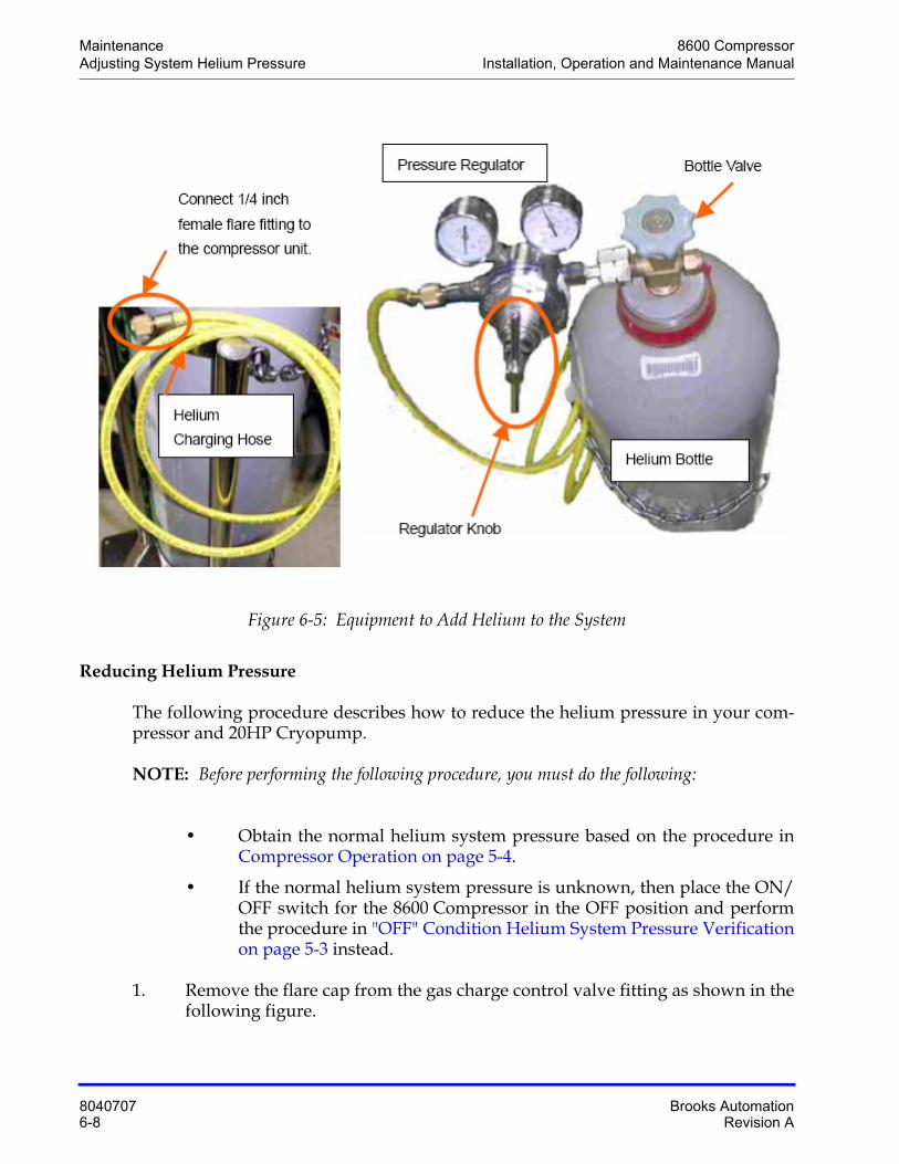
Maintenance 8600 CompressorAdjusting System Helium Pressure Installation, Operation and Maintenance Manual
8040707 Brooks Automation6-8 Revision A
Figure 6-5: Equipment to Add Helium to the System
Reducing Helium Pressure
The following procedure describes how to reduce the helium pressure in your com-pressor and 20HP Cryopump.
NOTE: Before performing the following procedure, you must do the following:
• Obtain the normal helium system pressure based on the procedure in Compressor Operation on page 5-4.
• If the normal helium system pressure is unknown, then place the ON/OFF switch for the 8600 Compressor in the OFF position and perform the procedure in "OFF" Condition Helium System Pressure Verificationon page 5-3 instead.
1. Remove the flare cap from the gas charge control valve fitting as shown in the following figure.
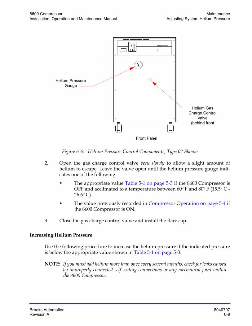
8600 Compressor MaintenanceInstallation, Operation and Maintenance Manual Adjusting System Helium Pressure
Brooks Automation 8040707Revision A 6-9
Figure 6-6: Helium Pressure Control Components, Type 02 Shown
2. Open the gas charge control valve very slowly to allow a slight amount of helium to escape. Leave the valve open until the helium pressure gauge indi-cates one of the following:
• The appropriate value Table 5-1 on page 5-3 if the 8600 Compressor is OFF and acclimated to a temperature between 60º F and 80º F (15.5º C - 26.6º C).
• The value previously recorded in Compressor Operation on page 5-4 if the 8600 Compressor is ON.
3. Close the gas charge control valve and install the flare cap.
Increasing Helium Pressure
Use the following procedure to increase the helium pressure if the indicated pressure is below the appropriate value shown in Table 5-1 on page 5-3.
NOTE: If you must add helium more than once every several months, check for leaks caused by improperly connected self-sealing connections or any mechanical joint within the 8600 Compressor.
8600Compressor
CTI-CRYOGENICSHELIX TECHNOLOGY CORPORATION
12345678
RSTCOM
PWR
RDY
Ch1RUN
STS
C‚R‚O‚o‚u R‚s
Helium Gas Charge Control
Valve (behind front
Helium Pressure Gauge
Front Panel
Maintenance 8600 CompressorAdjusting System Helium Pressure Installation, Operation and Maintenance Manual
8040707 Brooks Automation6-10 Revision A
You must obtain the normal helium system pressure from Compressor Operation on page 5-4 in order to perform this procedure. If the normal helium system pressure is unknown, then place the 8600 Compressor ON/OFF switch in the OFF position and perform the procedure in "OFF" Condition Helium System Pressure Verification on page 5-3 instead.
Contact Customer Support if the helium pressure gauge reads 0 psig.
This procedure ensures that both the regulator and the charging line will be purged of air and that the air trapped in the regulator will not diffuse back into the helium bot-tle. For best results, BROOKS-Cryogenics suggests a dedicated helium bottle, regula-tor and line (that are never separated) for adding helium.
NOTE: You are required to supply the helium charging line terminating in a 1/4-inch B male flare fitting, and a two-stage pressure regulator rated at 2-3MPa (gage) for this operation.
1. Attach a 290-435psi (2-3MPa) regulator and charging line to a helium bottle (99.999% pure).
NOTE: Do not open the helium bottle at this time.
Equipment Damage
To avoid contaminating and damaging the compressor and other system components, ensure the helium quality is 99.999% pure.
Equipment Damage
To avoid contaminating and damaging the compressor and other system components, do not open the helium bottle before you attach a regulator and charging line to it.
8600 Compressor MaintenanceInstallation, Operation and Maintenance Manual Adjusting System Helium Pressure
Brooks Automation 8040707Revision A 6-11
2. Purge the regulator and charging lines as follows:
a. Open the regulator a small amount by turning the adjusting knob clock-wise until it contacts the diaphragm, then turn approximately 1/8 to 1/4 turn more, so that the regulator is barely open.
b. Loosely connect the charge line to the helium pressure regulator.
c. Slowly open the bottle valve, and purge the regulator and line for 5 sec-onds.
d. Close the helium bottle by turning the regulator knob counterclockwise until the helium stops flowing.
3. Remove the 8600 Compressor front panel.
4. Remove the flare cap from the gas charge flared fitting (see Figure 6-6 on page 6-9).
5. Loosely connect the helium charging line from the helium pressure regulator to the 1/4-inch male B flare fitting installed on the helium charge valve.
6. Purge the charge line again, as in Step a, for 30 seconds.
7. Slightly open the charge valve.
8. Tighten the charge line flare fitting onto the gas charge fitting while the helium is flowing.
9. Set the two-stage regulator to 290psi (2MPa) (gage).
10. If the 8600 Compressor ON/OFF switch is in the ON position, proceed to the next step. If the 8600 Compressor ON/OFF switch is in the OFF position, pro-ceed to Step 12.
11. If the 8600 Compressor ON/OFF switch is in the ON position, obtain the pre-viously recorded normal system operating pressure from the Compressor Opera-tion on page 5-4 procedure. Open the gas charge control valve very slowly and allow helium to flow until the compressor gauge reading is the same as the value obtained. As soon as you reach the desired reading, quickly and tightly close the gas charge control valve. Proceed to Step 13.
12. If the 8600 Compressor ON/OFF switch is in the OFF position, obtain the appropriate (50 or 60 Hz) static helium system pressure from Table 5-1 on page 5-3. Open the gas charge control valve very slowly and allow helium to flow until the compressor gauge reading is the same as the appropriate value in Table 4-1
Maintenance 8600 CompressorAdjusting System Helium Pressure Installation, Operation and Maintenance Manual
8040707 Brooks Automation6-12 Revision A
on page 4-3. As soon as you reach the desired reading, quickly and tightly close the gas charge control valve. Proceed to Step 13.
NOTE: To avoid opening the safety relief valves, add the helium slowly.
13. Ensure that the helium charge valve on the 8600 Compressor is tightly closed. Shut off the helium pressure regulator on the helium bottle and remove the charging line from the male flare fitting. Then reinstall the flare cap.
8600 CompressorInstallation, Operation and Maintenance Manual
Brooks Automation 8040707Revision A 7-1
7 Appendices
Overview
The following appendices are included to provide the user with a single location for specific information related to the Brooks Automation Product.
Contents
Appendix A: Customer Brooks Automation Technical Support Information . . .7-2
Appendix B: Flow Diagram . . . . . . . . . . . . . . . . . . . . . . . . . . . . . . . . . . . . . . . . . . . . .7-3
Appendix C: Troubleshooting Procedures. . . . . . . . . . . . . . . . . . . . . . . . . . . . . . . . .7-68600 Compressor Error Messages . . . . . . . . . . . . . . . . . . . . . . . . . . . . . . . . . .7-6Troubleshooting when the NORMAL/C20 Switch is Set to NORMAL . .7-7Troubleshooting when the NORMAL/C20 Switch is Set to C/20 . . . . . . .7-8
Appendix D: Troubleshooting Procedures, Type 02 Only . . . . . . . . . . . . . . . . . . .7-13Alarm Sounds Continuously When Compressor is Turned On . . . . . . . . .7-13Alarm Code Description . . . . . . . . . . . . . . . . . . . . . . . . . . . . . . . . . . . . . . . . . .7-14
Appendix E: Electrical Schematic for the 8600 Compressor . . . . . . . . . . . . . . . . . .7-17
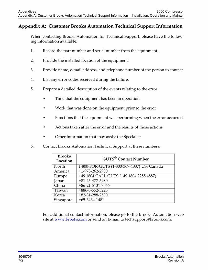
Appendices 8600 CompressorAppendix A: Customer Brooks Automation Technical Support Information Installation, Operation and Mainte-
8040707 Brooks Automation7-2 Revision A
Appendix A: Customer Brooks Automation Technical Support Information
When contacting Brooks Automation for Technical Support, please have the follow-ing information available.
1. Record the part number and serial number from the equipment.
2. Provide the installed location of the equipment.
3. Provide name, e-mail address, and telephone number of the person to contact.
4. List any error codes received during the failure.
5. Prepare a detailed description of the events relating to the error.
• Time that the equipment has been in operation
• Work that was done on the equipment prior to the error
• Functions that the equipment was performing when the error occurred
• Actions taken after the error and the results of those actions
• Other information that may assist the Specialist
6. Contact Brooks Automation Technical Support at these numbers:
For additional contact information, please go to the Brooks Automation web site at www.brooks.com or send an E-mail to [email protected].
Brooks Location GUTS® Contact Number
North America
1-800-FOR-GUTS (1-800-367-4887) US/Canada+1-978-262-2900
Europe +49 1804 CALL GUTS (+49 1804 2255 4887)Japan +81-45-477-5980China +86-21-5131-7066Taiwan +886-3-552-5225Korea +82-31-288-2500Singapore +65-6464-1481
8600 Compressor AppendicesInstallation, Operation and Maintenance Manual Appendix B: Flow Diagram
Brooks Automation 8040707Revision A 7-3
Appendix B: Flow Diagram
The 8600 Compressor flow diagram is shown in the following figure. The flow through the compressor starts when low-pressure helium gas returning from the cryopump cold head enters the compressor. A small quantity of oil is injected into the gas stream. Compression then transforms the low-pressure helium gas and oil to high-temperature and high-pressure helium gas. The oil, separated from the helium flow, pools at the bottom of the compressor and lubricates the inside of the compres-sor. Then, a portion of the heated oil goes through the oil injection line to be cooled and returns to the compressor.
The high-temperature and high-pressure helium gas from the compressor passes through the helium heat exchanger and is cooled down with water. Helium at a nor-mal temperature enters the oil separator, where the helium flow is separated into oil and helium gas. Separated oil runs through the oil return filter and orifice and once again meets with the low-pressure helium at the front of the compressor. Then helium gas and oil return to the compressor. The helium gas that came out of the oil separator goes through the adsorber to adsorb and remove the oil mist. Then, high-purity helium gas is supplied through a flexible hose to the cold head.
Note the safety devices in the compressor that are explained in the following figure.
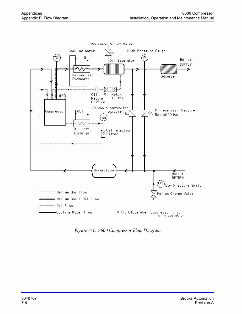
Appendices 8600 CompressorAppendix B: Flow Diagram Installation, Operation and Maintenance Manual
8040707 Brooks Automation7-4 Revision A
Figure 7-1: 8600 Compressor Flow Diagram
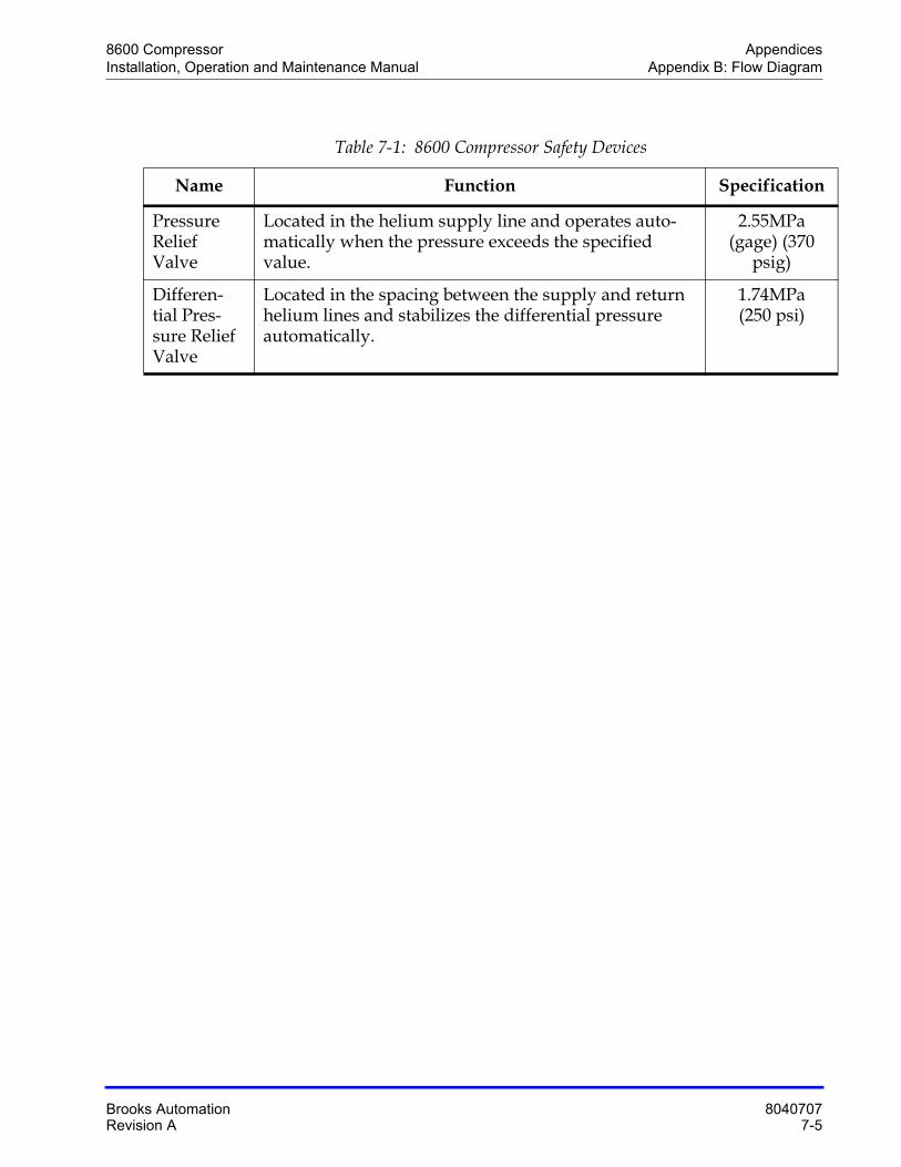
8600 Compressor AppendicesInstallation, Operation and Maintenance Manual Appendix B: Flow Diagram
Brooks Automation 8040707Revision A 7-5
Table 7-1: 8600 Compressor Safety Devices
Name Function Specification
Pressure Relief Valve
Located in the helium supply line and operates auto-matically when the pressure exceeds the specified value.
2.55MPa (gage) (370
psig)
Differen-tial Pres-sure Relief Valve
Located in the spacing between the supply and return helium lines and stabilizes the differential pressure automatically.
1.74MPa (250 psi)
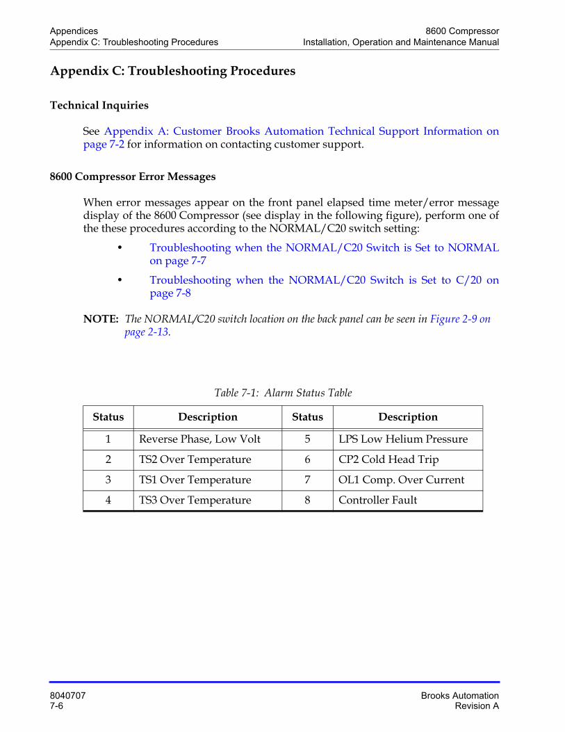
Appendices 8600 CompressorAppendix C: Troubleshooting Procedures Installation, Operation and Maintenance Manual
8040707 Brooks Automation7-6 Revision A
Appendix C: Troubleshooting Procedures
Technical Inquiries
See Appendix A: Customer Brooks Automation Technical Support Information on page 7-2 for information on contacting customer support.
8600 Compressor Error Messages
When error messages appear on the front panel elapsed time meter/error message display of the 8600 Compressor (see display in the following figure), perform one of the these procedures according to the NORMAL/C20 switch setting:
• Troubleshooting when the NORMAL/C20 Switch is Set to NORMALon page 7-7
• Troubleshooting when the NORMAL/C20 Switch is Set to C/20 on page 7-8
NOTE: The NORMAL/C20 switch location on the back panel can be seen in Figure 2-9 on page 2-13.
Table 7-1: Alarm Status Table
Status Description Status Description
1 Reverse Phase, Low Volt 5 LPS Low Helium Pressure
2 TS2 Over Temperature 6 CP2 Cold Head Trip
3 TS1 Over Temperature 7 OL1 Comp. Over Current
4 TS3 Over Temperature 8 Controller Fault
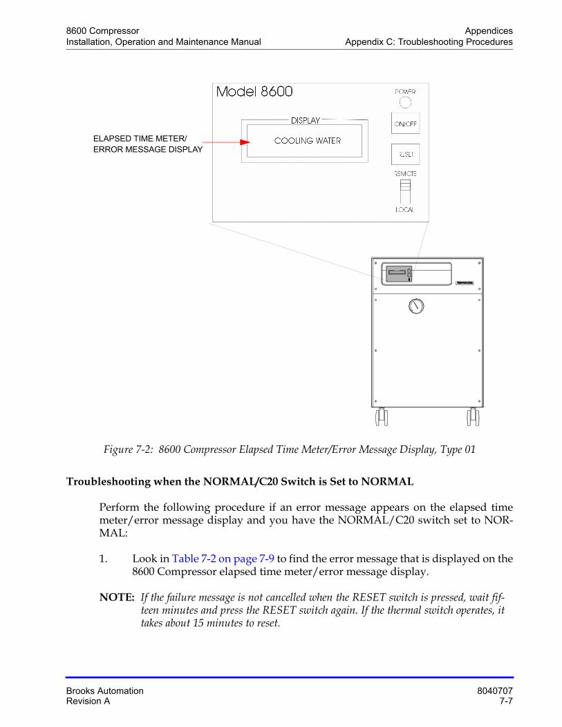
8600 Compressor AppendicesInstallation, Operation and Maintenance Manual Appendix C: Troubleshooting Procedures
Brooks Automation 8040707Revision A 7-7
Figure 7-2: 8600 Compressor Elapsed Time Meter/Error Message Display, Type 01
Troubleshooting when the NORMAL/C20 Switch is Set to NORMAL
Perform the following procedure if an error message appears on the elapsed time meter/error message display and you have the NORMAL/C20 switch set to NOR-MAL:
1. Look in Table 7-2 on page 7-9 to find the error message that is displayed on the 8600 Compressor elapsed time meter/error message display.
NOTE: If the failure message is not cancelled when the RESET switch is pressed, wait fif-teen minutes and press the RESET switch again. If the thermal switch operates, it takes about 15 minutes to reset.
ELAPSED TIME METER/
ERROR MESSAGE DISPLAY
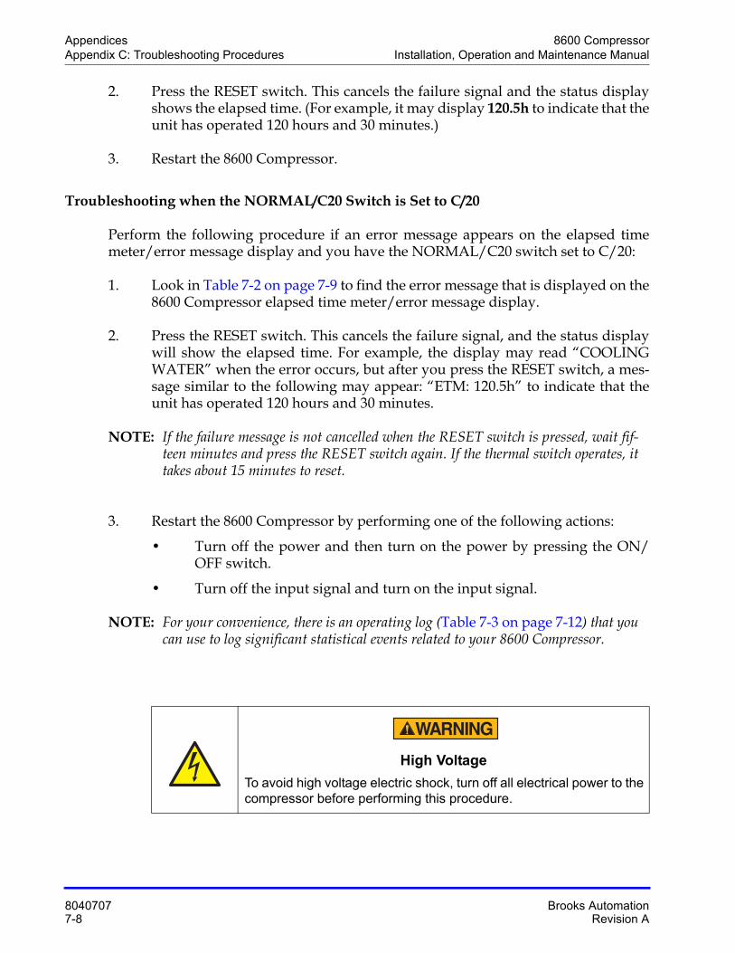
Appendices 8600 CompressorAppendix C: Troubleshooting Procedures Installation, Operation and Maintenance Manual
8040707 Brooks Automation7-8 Revision A
2. Press the RESET switch. This cancels the failure signal and the status display shows the elapsed time. (For example, it may display 120.5h to indicate that the unit has operated 120 hours and 30 minutes.)
3. Restart the 8600 Compressor.
Troubleshooting when the NORMAL/C20 Switch is Set to C/20
Perform the following procedure if an error message appears on the elapsed time meter/error message display and you have the NORMAL/C20 switch set to C/20:
1. Look in Table 7-2 on page 7-9 to find the error message that is displayed on the 8600 Compressor elapsed time meter/error message display.
2. Press the RESET switch. This cancels the failure signal, and the status display will show the elapsed time. For example, the display may read “COOLING WATER” when the error occurs, but after you press the RESET switch, a mes-sage similar to the following may appear: “ETM: 120.5h” to indicate that the unit has operated 120 hours and 30 minutes.
NOTE: If the failure message is not cancelled when the RESET switch is pressed, wait fif-teen minutes and press the RESET switch again. If the thermal switch operates, it takes about 15 minutes to reset.
3. Restart the 8600 Compressor by performing one of the following actions:
• Turn off the power and then turn on the power by pressing the ON/OFF switch.
• Turn off the input signal and turn on the input signal.
NOTE: For your convenience, there is an operating log (Table 7-3 on page 7-12) that you can use to log significant statistical events related to your 8600 Compressor.
High Voltage
To avoid high voltage electric shock, turn off all electrical power to the compressor before performing this procedure.
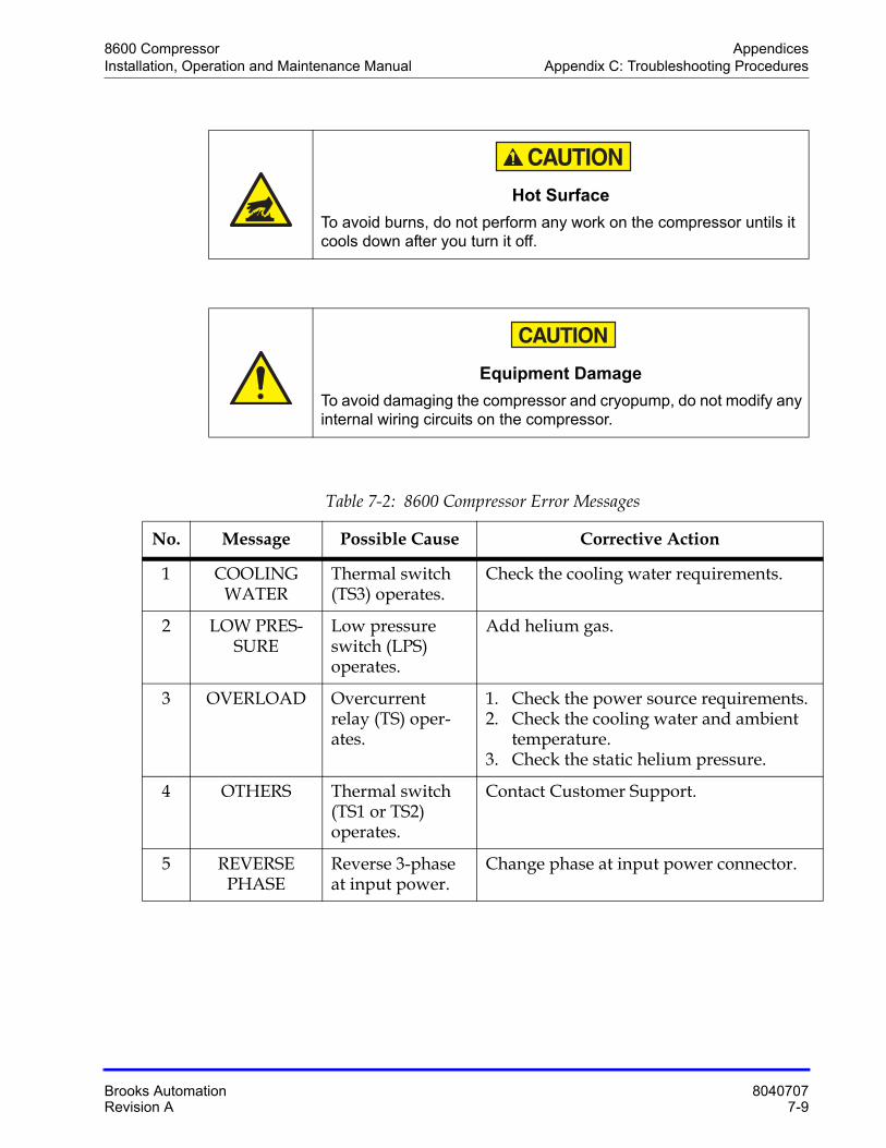
8600 Compressor AppendicesInstallation, Operation and Maintenance Manual Appendix C: Troubleshooting Procedures
Brooks Automation 8040707Revision A 7-9
Hot Surface
To avoid burns, do not perform any work on the compressor untils it cools down after you turn it off.
Equipment Damage
To avoid damaging the compressor and cryopump, do not modify any internal wiring circuits on the compressor.
Table 7-2: 8600 Compressor Error Messages
No. Message Possible Cause Corrective Action
1 COOLING WATER
Thermal switch (TS3) operates.
Check the cooling water requirements.
2 LOW PRES-SURE
Low pressure switch (LPS) operates.
Add helium gas.
3 OVERLOAD Overcurrent relay (TS) oper-ates.
1. Check the power source requirements.2. Check the cooling water and ambient
temperature.3. Check the static helium pressure.
4 OTHERS Thermal switch (TS1 or TS2) operates.
Contact Customer Support.
5 REVERSE PHASE
Reverse 3-phase at input power.
Change phase at input power connector.
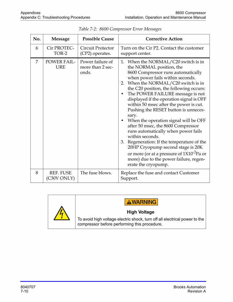
Appendices 8600 CompressorAppendix C: Troubleshooting Procedures Installation, Operation and Maintenance Manual
8040707 Brooks Automation7-10 Revision A
6 Cir PROTEC-TOR-2
Circuit Protector (CP2) operates.
Turn on the Cir P2. Contact the customer support center.
7 POWER FAIL-URE
Power failure of more than 2 sec-onds.
1. When the NORMAL/C20 switch is in the NORMAL position, the 8600 Compressor runs automatically when power fails within seconds.
2. When the NORMAL/C20 switch is in the C20 position, the following occurs:
• The POWER FAILURE message is not displayed if the operation signal is OFF within 50 msec after the power is cut. Pushing the RESET button is unneces-sary.
• When the operation signal will be OFF after 50 msec, the 8600 Compressor runs automatically when power fails within seconds.
3. Regeneration: If the temperature of the 20HP Cryopump second stage is 20K or more (or at a pressure of 1X10⁻²Pa or more) due to the power failure, regen-erate the cryopump.
8 REF. FUSE (C30V ONLY)
The fuse blows. Replace the fuse and contact Customer Support.
High Voltage
To avoid high voltage electric shock, turn off all electrical power to the compressor before performing this procedure.
Table 7-2: 8600 Compressor Error Messages
No. Message Possible Cause Corrective Action
8600 Compressor AppendicesInstallation, Operation and Maintenance Manual Appendix C: Troubleshooting Procedures
Brooks Automation 8040707Revision A 7-11
When an irregular stop occurs due to a failure not listed in Table 7-2 on page 7-9, power cycle the compressor by shutting off the power supply and then turning it on.
Hot Surface
To avoid burns, do not perform any work on the compressor untils it cools down after you turn it off.
Equipment Damage
To avoid damaging the compressor and cryopump, do not modify any internal wiring circuits on the compressor.
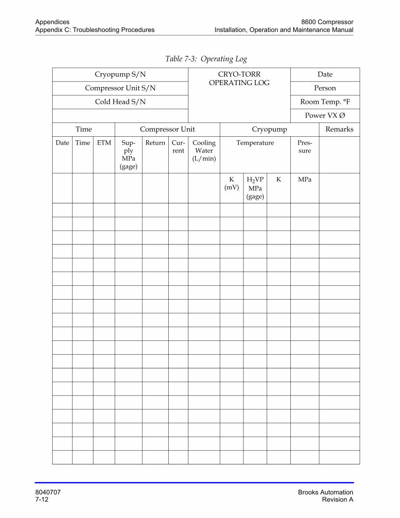
Appendices 8600 CompressorAppendix C: Troubleshooting Procedures Installation, Operation and Maintenance Manual
8040707 Brooks Automation7-12 Revision A
Table 7-3: Operating Log
Cryopump S/N CRYO-TORROPERATING LOG
Date
Compressor Unit S/N Person
Cold Head S/N Room Temp. °F
Power VX Ø
Time Compressor Unit Cryopump Remarks
Date Time ETM Sup-ply
MPa (gage)
Return Cur-rent
Cooling Water
(L/min)
Temperature Pres-sure
K (mV)
H2VP MPa
(gage)
K MPa
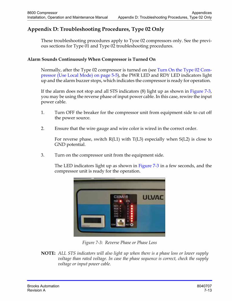
8600 Compressor AppendicesInstallation, Operation and Maintenance Manual Appendix D: Troubleshooting Procedures, Type 02 Only
Brooks Automation 8040707Revision A 7-13
Appendix D: Troubleshooting Procedures, Type 02 Only
These troubleshooting procedures apply to Tyoe 02 compressors only. See the previ-ous sections for Type 01 and Type 02 troubleshooting procedures.
Alarm Sounds Continuously When Compressor is Turned On
Normally, after the Type 02 compressor is turned on (see Turn On the Type 02 Com-pressor (Use Local Mode) on page 5-5), the PWR LED and RDY LED indicators light up and the alarm buzzer stops, which indicates the compressor is ready for operation.
If the alarm does not stop and all STS indicators (8) light up as shown in Figure 7-3, you may be using the reverse phase of input power cable. In this case, rewire the input power cable.
1. Turn OFF the breaker for the compressor unit from equipment side to cut off the power source.
2. Ensure that the wire gauge and wire color is wired in the correct order.
For reverse phase, switch R(L1) with T(L3) especially when S(L2) is close to GND potential.
3. Turn on the compressor unit from the equipment side.
The LED indicators light up as shown in Figure 7-3 in a few seconds, and the compressor unit is ready for the operation.
Figure 7-3: Reverse Phase or Phase Loss
NOTE: ALL STS indicators will also light up when there is a phase loss or lower supply voltage than rated voltage. In case the phase sequence is correct, check the supply voltage or input power cable.
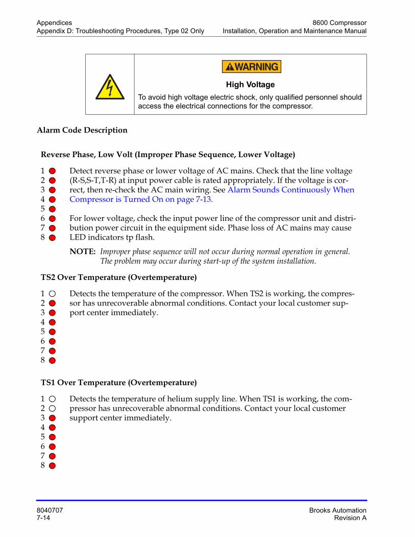
Appendices 8600 CompressorAppendix D: Troubleshooting Procedures, Type 02 Only Installation, Operation and Maintenance Manual
8040707 Brooks Automation7-14 Revision A
Alarm Code Description
High Voltage
To avoid high voltage electric shock, only qualified personnel should access the electrical connections for the compressor.
Reverse Phase, Low Volt (Improper Phase Sequence, Lower Voltage)
12345678
Detect reverse phase or lower voltage of AC mains. Check that the line voltage (R-S,S-T,T-R) at input power cable is rated appropriately. If the voltage is cor-rect, then re-check the AC main wiring. See Alarm Sounds Continuously When Compressor is Turned On on page 7-13.
For lower voltage, check the input power line of the compressor unit and distri-bution power circuit in the equipment side. Phase loss of AC mains may cause LED indicators tp flash.
NOTE: Improper phase sequence will not occur during normal operation in general. The problem may occur during start-up of the system installation.
TS2 Over Temperature (Overtemperature)
12345678
Detects the temperature of the compressor. When TS2 is working, the compres-sor has unrecoverable abnormal conditions. Contact your local customer sup-port center immediately.
TS1 Over Temperature (Overtemperature)
12345678
Detects the temperature of helium supply line. When TS1 is working, the com-pressor has unrecoverable abnormal conditions. Contact your local customer support center immediately.
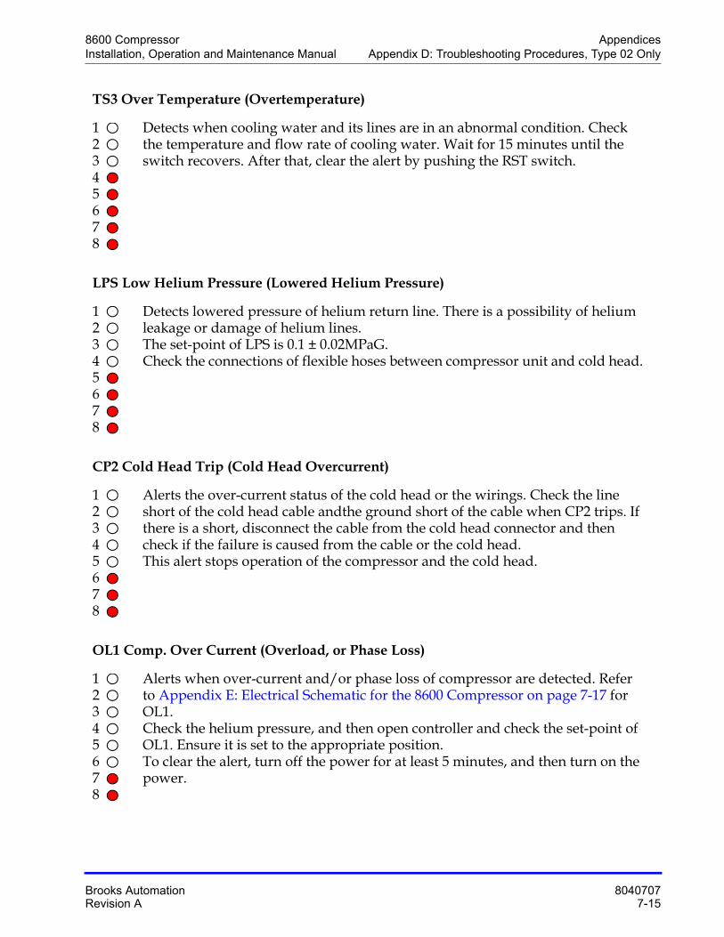
8600 Compressor AppendicesInstallation, Operation and Maintenance Manual Appendix D: Troubleshooting Procedures, Type 02 Only
Brooks Automation 8040707Revision A 7-15
TS3 Over Temperature (Overtemperature)
12345678
Detects when cooling water and its lines are in an abnormal condition. Check the temperature and flow rate of cooling water. Wait for 15 minutes until the switch recovers. After that, clear the alert by pushing the RST switch.
LPS Low Helium Pressure (Lowered Helium Pressure)
12345678
Detects lowered pressure of helium return line. There is a possibility of helium leakage or damage of helium lines.The set-point of LPS is 0.1 ± 0.02MPaG.Check the connections of flexible hoses between compressor unit and cold head.
CP2 Cold Head Trip (Cold Head Overcurrent)
12345678
Alerts the over-current status of the cold head or the wirings. Check the line short of the cold head cable andthe ground short of the cable when CP2 trips. If there is a short, disconnect the cable from the cold head connector and then check if the failure is caused from the cable or the cold head.This alert stops operation of the compressor and the cold head.
OL1 Comp. Over Current (Overload, or Phase Loss)
12345678
Alerts when over-current and/or phase loss of compressor are detected. Refer to Appendix E: Electrical Schematic for the 8600 Compressor on page 7-17 for OL1.Check the helium pressure, and then open controller and check the set-point of OL1. Ensure it is set to the appropriate position.To clear the alert, turn off the power for at least 5 minutes, and then turn on the power.
Appendices 8600 CompressorAppendix D: Troubleshooting Procedures, Type 02 Only Installation, Operation and Maintenance Manual
8040707 Brooks Automation7-16 Revision A
Controller Fault
12345678
Control module always checks the hardware for the safety operation. The alert indicates MC fault during running operation, loosened wiring in controller. When the alert occurrs, turn OFF power of the compressor unit and check the loosened wirings if it is possible. After a few minutes have passed, turn the power ON. If the same alert occurs again, contact Customer Service.
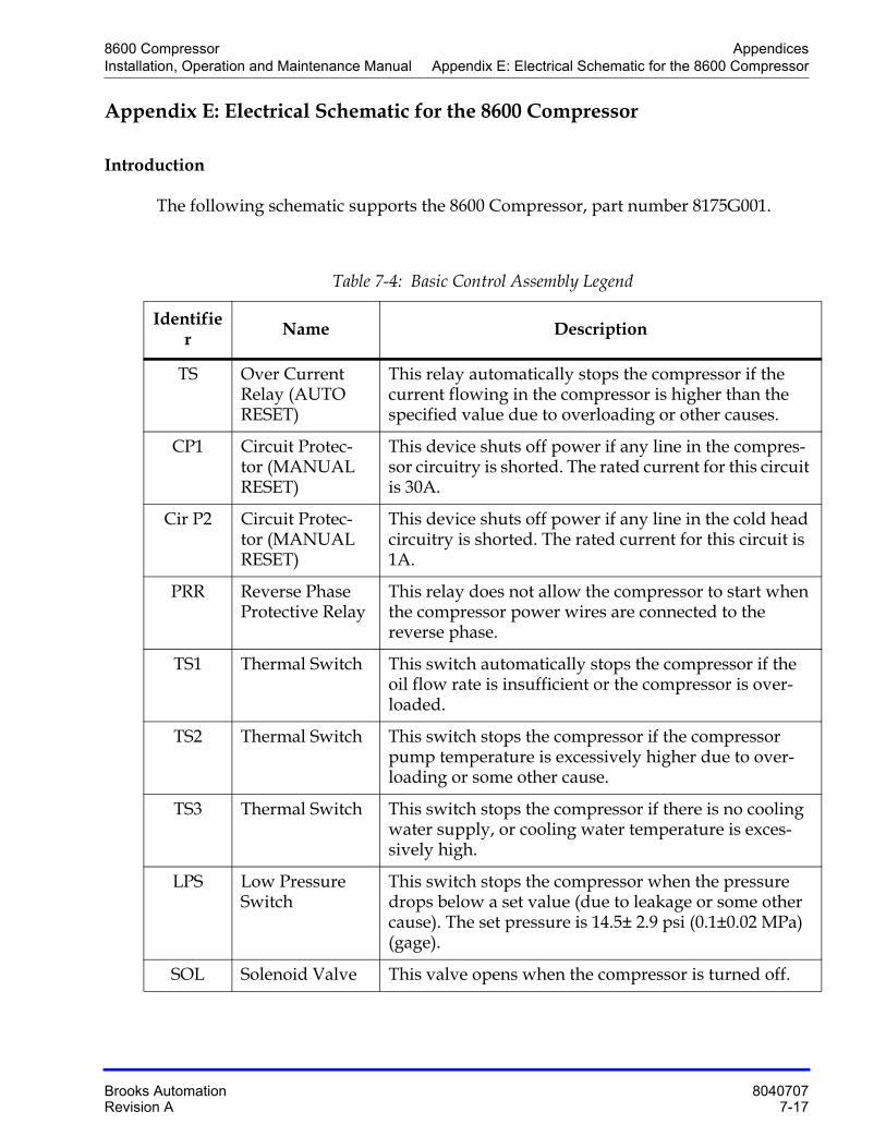
8600 Compressor AppendicesInstallation, Operation and Maintenance Manual Appendix E: Electrical Schematic for the 8600 Compressor
Brooks Automation 8040707Revision A 7-17
Appendix E: Electrical Schematic for the 8600 Compressor
Introduction
The following schematic supports the 8600 Compressor, part number 8175G001.
Table 7-4: Basic Control Assembly Legend
Identifier Name Description
TS Over Current Relay (AUTO RESET)
This relay automatically stops the compressor if the current flowing in the compressor is higher than the specified value due to overloading or other causes.
CP1 Circuit Protec-tor (MANUAL RESET)
This device shuts off power if any line in the compres-sor circuitry is shorted. The rated current for this circuit is 30A.
Cir P2 Circuit Protec-tor (MANUAL RESET)
This device shuts off power if any line in the cold head circuitry is shorted. The rated current for this circuit is 1A.
PRR Reverse Phase Protective Relay
This relay does not allow the compressor to start when the compressor power wires are connected to the reverse phase.
TS1 Thermal Switch This switch automatically stops the compressor if the oil flow rate is insufficient or the compressor is over-loaded.
TS2 Thermal Switch This switch stops the compressor if the compressor pump temperature is excessively higher due to over-loading or some other cause.
TS3 Thermal Switch This switch stops the compressor if there is no cooling water supply, or cooling water temperature is exces-sively high.
LPS Low Pressure Switch
This switch stops the compressor when the pressure drops below a set value (due to leakage or some other cause). The set pressure is 14.5± 2.9 psi (0.1±0.02 MPa) (gage).
SOL Solenoid Valve This valve opens when the compressor is turned off.
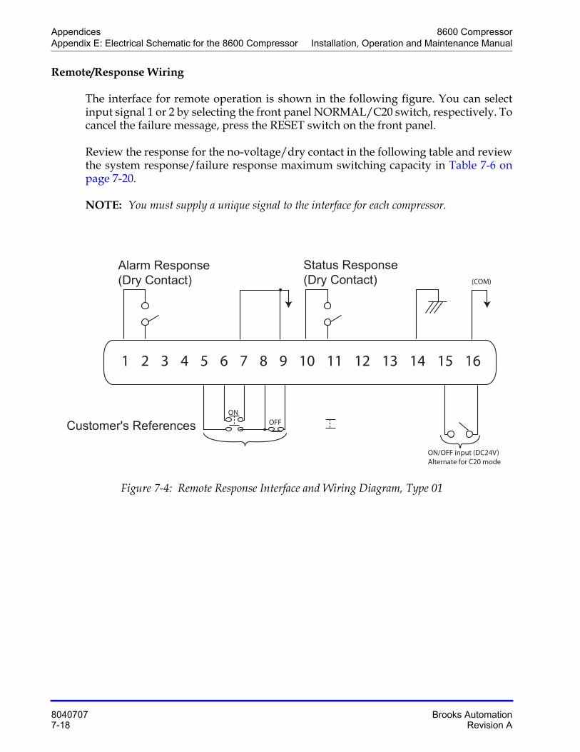
Appendices 8600 CompressorAppendix E: Electrical Schematic for the 8600 Compressor Installation, Operation and Maintenance Manual
8040707 Brooks Automation7-18 Revision A
Remote/Response Wiring
The interface for remote operation is shown in the following figure. You can select input signal 1 or 2 by selecting the front panel NORMAL/C20 switch, respectively. To cancel the failure message, press the RESET switch on the front panel.
Review the response for the no-voltage/dry contact in the following table and review the system response/failure response maximum switching capacity in Table 7-6 on page 7-20.
NOTE: You must supply a unique signal to the interface for each compressor.
Figure 7-4: Remote Response Interface and Wiring Diagram, Type 01
1 2 3 4 5 6 7 8 9 10 11 12 13 14 15 16
Alarm Response
(Dry Contact)
Customer's References
Status Response
(Dry Contact)
ON
ON/OFF input (DC24V)Alternate for C20 mode
OFF
(COM)
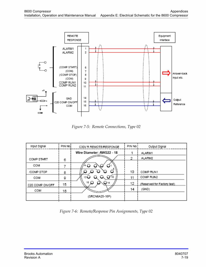
8600 Compressor AppendicesInstallation, Operation and Maintenance Manual Appendix E: Electrical Schematic for the 8600 Compressor
Brooks Automation 8040707Revision A 7-19
Figure 7-5: Remote Connections, Type 02
Figure 7-6: Remote/Response Pin Assignments, Type 02
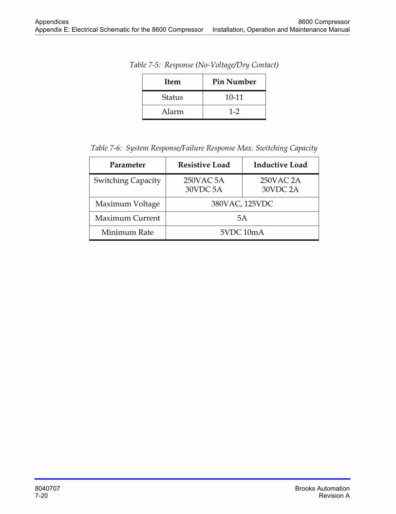
Appendices 8600 CompressorAppendix E: Electrical Schematic for the 8600 Compressor Installation, Operation and Maintenance Manual
8040707 Brooks Automation7-20 Revision A
Table 7-5: Response (No-Voltage/Dry Contact)
Item Pin Number
Status 10-11
Alarm 1-2
Table 7-6: System Response/Failure Response Max. Switching Capacity
Parameter Resistive Load Inductive Load
Switching Capacity 250VAC 5A30VDC 5A
250VAC 2A30VDC 2A
Maximum Voltage 380VAC, 125VDC
Maximum Current 5A
Minimum Rate 5VDC 10mA
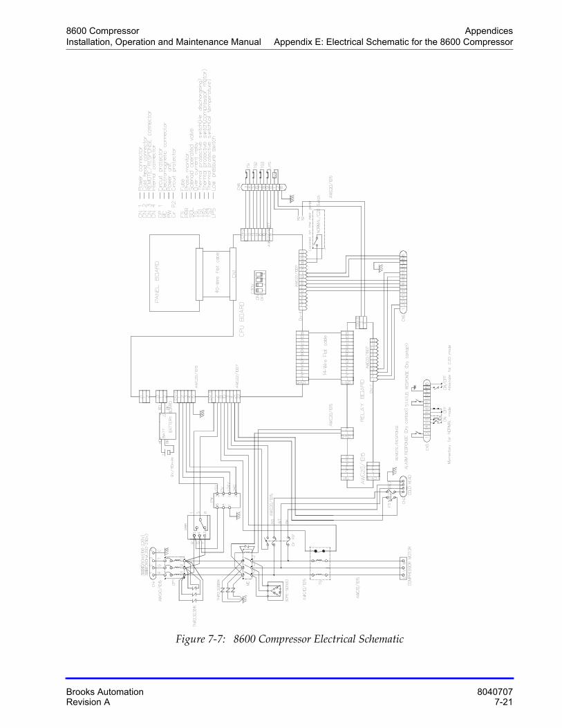
8600 Compressor AppendicesInstallation, Operation and Maintenance Manual Appendix E: Electrical Schematic for the 8600 Compressor
Brooks Automation 8040707Revision A 7-21
Figure 7-7: 8600 Compressor Electrical Schematic

Appendices 8600 CompressorAppendix E: Electrical Schematic for the 8600 Compressor Installation, Operation and Maintenance Manual
8040707 Brooks Automation7-22 Revision A
This Page Intentionally Left Blank
8600 CompressorInstallation, Operation and Maintenance Manual
Brooks Automation 8040707Revision A Index-1
Index
Numerics8600 Compression Installation
Flowchart 4-28600 Compressor Error Messages 7-68600 Compressor Safety Devices 7-58600 Compressor Storage 4-18
AAdjusting System Helium Pressure 6-6Adsorber Replacement 6-2
BBasic Control Assembly Legend 7-17Brooks Automation
contact information Front-ii
CCir P2 Circuit Protector 2-20Clearance Requirements 4-3COLD HEAD POWER Connector 2-18Compressor 3-2Compressor Flow Diagram 7-3Compressor Troubleshooting Procedures 7-
9Connecting Flexible Helium Lines 4-11Connecting Helium Flex Lines 4-11Connections
Return and Supply Water Line 4-4Cooling Water INLET 2-20Cooling Water OUT 2-21Cooling Water OUTLET 2-21CP1 Circuit Protector 2-20Cryopump Connections, Cryo-Torr 20HP 4-
14Cryopump Electrical Outlet 2-21, 2-21
Cryo-Torr 20HP Cryopump Connections 4-14, 4-14
DDisconnecting Helium Flex Lines 4-13, 4-13
EElapsed Time Meter 2-23Elapsed Time Meter/Error Message Display
2-23, 2-23Electrical Connections 4-7, 4-7, 4-8Environmental Specifications 4-3Error Message Display 2-23Error Messages, 8600 Compressor Display 7-
6
FFlow Diagram
Compressor 7-3Fuse Panel 2-19
HHard Water Lines 4-5Helium “OFF” Condition 3-2Helium Circuit Components
Replacing 5-9Helium Flex Lines, Connecting and Discon-
necting 4-11Helium Gas Charge Control Valve 2-21, 2-21Helium Pressure
Increasing 6-9Reducing 6-8
Helium Pressure Gauge 2-21, 2-21Helium Return Line Coupling 2-22Helium Supply Line Coupling 2-22
Index 8600 CompressorInstallation, Operation and Maintenance Manual
8040707 Brooks AutomationIndex-2 Revision A
IIncreasing Helium Pressure 6-9INPUT POWER 2-19Installation Flowchart
8600 Compression 4-2Installing Flexible Water Lines 4-6Installing Hard Water Lines 4-5
LL/H Switch 2-19
NNORMAL/C20 Switch 2-19
OON/OFF Switch 2-16Operating Log 7-12Operating the Compressor 5-4
PPower Connector 2-22Power Indicator 2-16Power Inlet 2-22Powering On the 8600 Compressor and
Troubleshooting Diagnostic Prob-lems 5-8
Prerequisites to Installing Supply and Re-turn Water Line Connections 4-4
ProceduresCompressor Troubleshooting 7-9
RReducing Helium Pressure 6-8Ref Fuse 2-20REMOTE RESPONSE 2-19REMOTE/LOCAL Switch 2-16Replacing Helium Circuit Components 5-9RESET Switch 2-16Return Gas Coupling 2-22
SSafety precautions 1-2Scheduled Maintenance 6-2, 6-2
Shipping Carton Contents 3-3Shipping Carton Inspection 3-2, 3-2Static Helium System Pressure
Verification 3-2Suggested Maintenance Equipment 6-2, 6-2Supply and Return Water Line Connections
4-4, 4-4Supply Gas Coupling 2-22System Helium Pressure
Adjusting 6-6
TTechnical Inquiries 7-6Troubleshooting 7-6
switch set to C/20 7-8switch set to NORMAL 7-7