82-04 s10 pickup / blazer & zr2 models...
TRANSCRIPT
Thank you for choosing Rough Country for all your suspension needs. Rough Country recommends a certified technician install this system. In addition to these instructions, professional knowledge of disassemble/reassembly procedures as well as post installation checks must be known. Attempts to install this system without this knowledge and expertise may jeopardize the integrity and/or operating safety of the vehicle. Please read instructions before beginning installation. Check the kit hardware against the product layout and kit contents information on these instructions. Be sure you have all needed parts and know where they go. Also please review tools needed list and make sure you have needed tools.
PRODUCT USE INFORMATION
As a general rule, the taller a vehicle is, the easier it will roll. Seat belts and shoulder harnesses should be worn at all times. Avoid situations where a side rollover may occur. Generally, braking performance and capability are decreased when larger/heavier tires and wheels are used. Take this into consideration while driving. Do not add, alter, or fabricate any factory or after-market parts to increase vehicle height over the intended height of the Rough Country product pur-chased. Mixing component brands is not recommended.
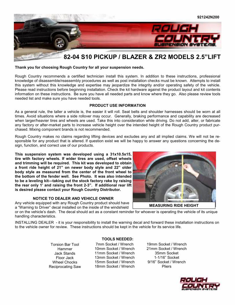
Rough Country makes no claims regarding lifting devices and excludes any and all implied claims. We will not be re-sponsible for any product that is altered. If question exist we will be happy to answer any questions concerning the de-sign, function, and correct use of our products. This suspension system was developed using a 31x10.5x15, tire with factory wheels. If wider tires are used, offset wheels and trimming will be required. This kit was developed to obtain a front ride height of 21” on newer body style and 22” older body style as measured from the center of the front wheel to the bottom of the fender well. See Photo. It was also intended to be a leveling kit—taking out the stock factory rake by raising the rear only 1’ and raising the front 2-3”. If additional rear lift is desired please contact your Rough Country Distributor.
NOTICE TO DEALER AND VEHICLE OWNER Any vehicle equipped with any Rough Country product should have a “Warning to Driver” decal installed on the inside of the windshield or on the vehicle’s dash. The decal should act as a constant reminder for whoever is operating the vehicle of its unique handling characteristics.
INSTALLING DEALER - it is your responsibility to install the warning decal and forward these installation instructions on to the vehicle owner for review. These instructions should be kept in the vehicle for its service life.
82-04 S10 PICKUP / BLAZER & ZR2 MODELS 2.5”LIFT
921242N200
MEASURING RIDE HEIGHT
TOOLS NEEDED:
Torsion Bar Tool Hammer
Jack Stands Floor Jack
Wheel Chocks Reciprocating Saw
7mm Socket / Wrench 10mm Socket / Wrench 11mm Socket / Wrench 13mm Socket / Wrench 15mm Socket / Wrench 18mm Socket / Wrench
19mm Socket / Wrench 21mm Socket / Wrench
35mm Socket 1-1/16” Socket
9/16” Socket / Wrench Pliers
INSTALLATION INSTRUCTIONS
1. Chock rear wheels where the truck will not roll. Place vehicle in neutral.
2. Raise the front with a floor jack, positioned underneath the front axle cross member. Place jack stands under the frame rails, behind the front wheel wells and lower frame onto jack stands. Remove the front tires.
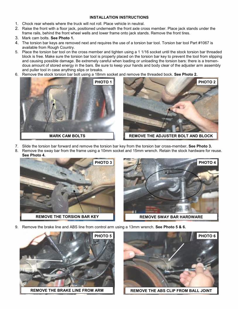
3. Mark cam bolts. See Photo 1. 4. The torsion bar keys are removed next and requires the use of a torsion bar tool. Torsion bar tool Part #1067 is
available from Rough Country. 5. Place the torsion bar tool on the cross member and tighten using a 1 1/16 socket until the stock torsion bar threaded
block is free. Make sure the torsion bar tool is properly placed on the torsion bar key to prevent the tool from slipping and causing possible damage. Be extremely careful when loading or unloading the torsion bars: there is a tremen-dous amount of stored energy in the bars. Be sure to keep your hands and body clear of the adjuster arm assembly and puller tool in case anything slips or breaks.
6. Remove the stock torsion bar bolt using a 18mm socket and remove the threaded bock. See Photo 2.
7. Slide the torsion bar forward and remove the torsion bar key from the torsion bar cross-member. See Photo 3. 8. Remove the sway bar from the frame using a 10mm socket and 15mm wrench. Retain the stock hardware for reuse.
See Photo 4.
9. Remove the brake line and ABS line from control arm using a 13mm wrench. See Photo 5 & 6.
REMOVE THE TORSION BAR KEY REMOVE SWAY BAR HARDWARE
REMOVE THE BRAKE LINE FROM ARM REMOVE THE ABS CLIP FROM BALL JOINT
PHOTO 1 PHOTO 2
PHOTO 3 PHOTO 4
PHOTO 5 PHOTO 6
REMOVE THE ADJUSTER BOLT AND BLOCK MARK CAM BOLTS
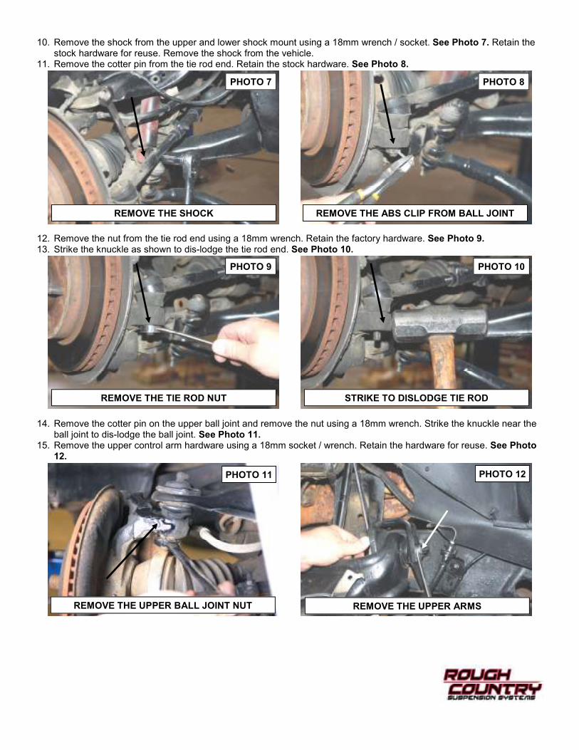
10. Remove the shock from the upper and lower shock mount using a 18mm wrench / socket. See Photo 7. Retain the stock hardware for reuse. Remove the shock from the vehicle.
11. Remove the cotter pin from the tie rod end. Retain the stock hardware. See Photo 8.
12. Remove the nut from the tie rod end using a 18mm wrench. Retain the factory hardware. See Photo 9. 13. Strike the knuckle as shown to dis-lodge the tie rod end. See Photo 10.
14. Remove the cotter pin on the upper ball joint and remove the nut using a 18mm wrench. Strike the knuckle near the ball joint to dis-lodge the ball joint. See Photo 11.
15. Remove the upper control arm hardware using a 18mm socket / wrench. Retain the hardware for reuse. See Photo 12.
REMOVE THE ABS CLIP FROM BALL JOINT REMOVE THE SHOCK
REMOVE THE TIE ROD NUT STRIKE TO DISLODGE TIE ROD
REMOVE THE UPPER BALL JOINT NUT REMOVE THE UPPER ARMS
PHOTO 8 PHOTO 7
PHOTO 9 PHOTO 10
PHOTO 11 PHOTO 12
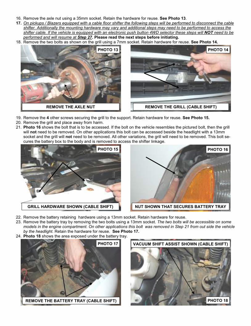
16. Remove the axle nut using a 35mm socket. Retain the hardware for reuse. See Photo 13. 17. On pickups / Blazers equipped with a cable floor shifter the following steps will be performed to disconnect the cable
shifter. Additionally the mounting hardware may vary and additional steps may need to be performed to access the shifter cable. If the vehicle is equipped with an electronic push button 4WD selector these steps will NOT need to be performed and will resume at Step 27. Please read the next steps before initiating.
18. Remove the two bolts as shown on the grill using a 7mm socket. Retain hardware for reuse. See Photo 14.
19. Remove the 4 other screws securing the grill to the support. Retain hardware for reuse. See Photo 15. 20. Remove the grill and place away from harm. 21. Photo 16 shows the bolt that is to be accessed. If the bolt on the vehicle resembles the pictured bolt, then the grill
will not need to be removed. On other applications this bolt can be accessed beside the headlight with a 13mm socket and the grill will not need to be removed. All other variations, the grill will need to be removed. This bolt se-cures the battery box to the body and is removed to access the shifter linkage.
22. Remove the battery retaining hardware using a 13mm socket. Retain hardware for reuse. 23. Remove the battery tray by removing the two bolts using a 13mm socket. The two bolts will be accessible on some
models in the engine compartment. On other applications this bolt was removed in Step 21 from out side the vehicle by the headlight. Retain the hardware for reuse. See Photo 17.
24. Photo 18 shows the area exposed under the battery tray.
REMOVE THE AXLE NUT REMOVE THE GRILL (CABLE SHIFT)
GRILL HARDWARE SHOWN (CABLE SHIFT) NUT SHOWN THAT SECURES BATTERY TRAY
VACUUM SHIFT ASSIST SHOWN (CABLE SHIFT)
PHOTO 13 PHOTO 14
PHOTO 15 PHOTO 16
PHOTO 17
PHOTO 18 REMOVE THE BATTERY TRAY (CABLE SHIFT)
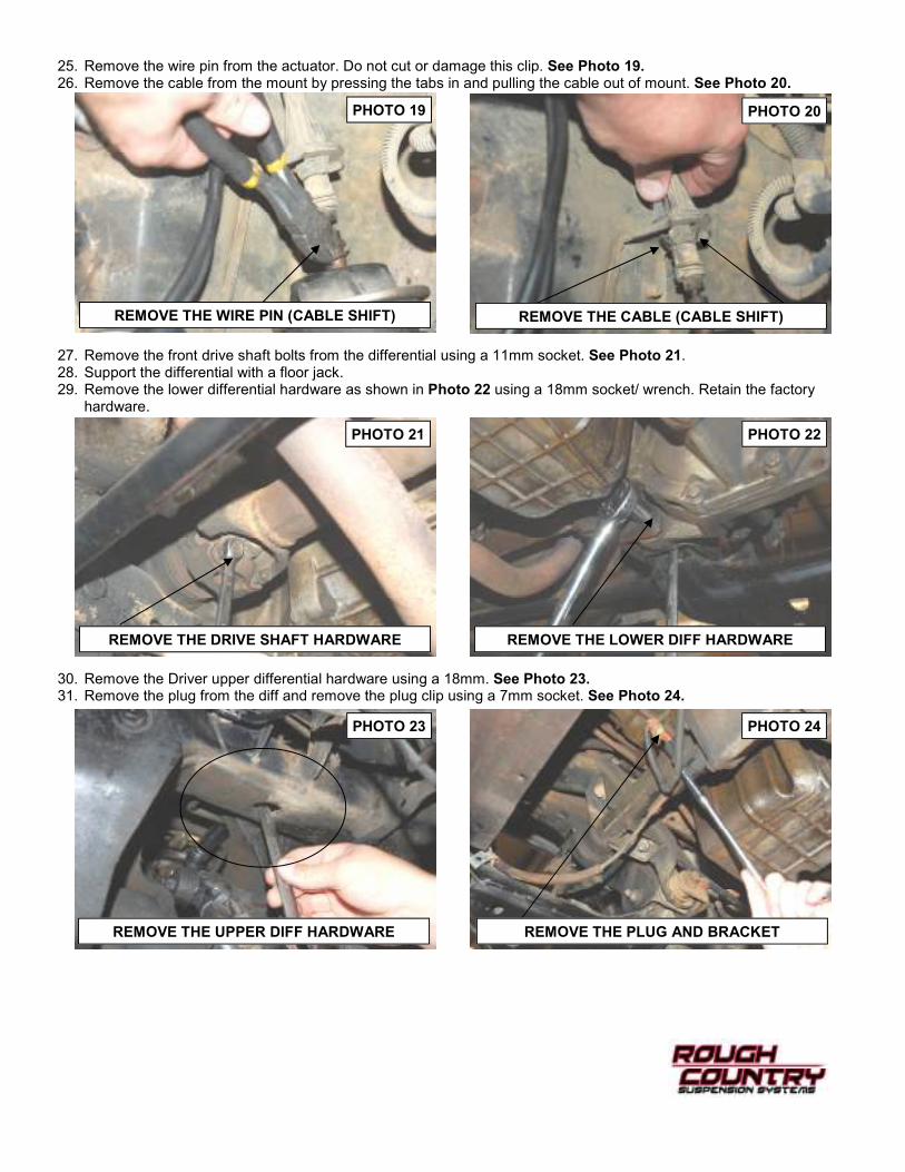
25. Remove the wire pin from the actuator. Do not cut or damage this clip. See Photo 19. 26. Remove the cable from the mount by pressing the tabs in and pulling the cable out of mount. See Photo 20.
27. Remove the front drive shaft bolts from the differential using a 11mm socket. See Photo 21. 28. Support the differential with a floor jack. 29. Remove the lower differential hardware as shown in Photo 22 using a 18mm socket/ wrench. Retain the factory
hardware.
30. Remove the Driver upper differential hardware using a 18mm. See Photo 23. 31. Remove the plug from the diff and remove the plug clip using a 7mm socket. See Photo 24.
REMOVE THE CABLE (CABLE SHIFT)
REMOVE THE DRIVE SHAFT HARDWARE REMOVE THE LOWER DIFF HARDWARE
REMOVE THE UPPER DIFF HARDWARE REMOVE THE PLUG AND BRACKET
PHOTO 19 PHOTO 20
PHOTO 21 PHOTO 22
PHOTO 23 PHOTO 24
REMOVE THE WIRE PIN (CABLE SHIFT)
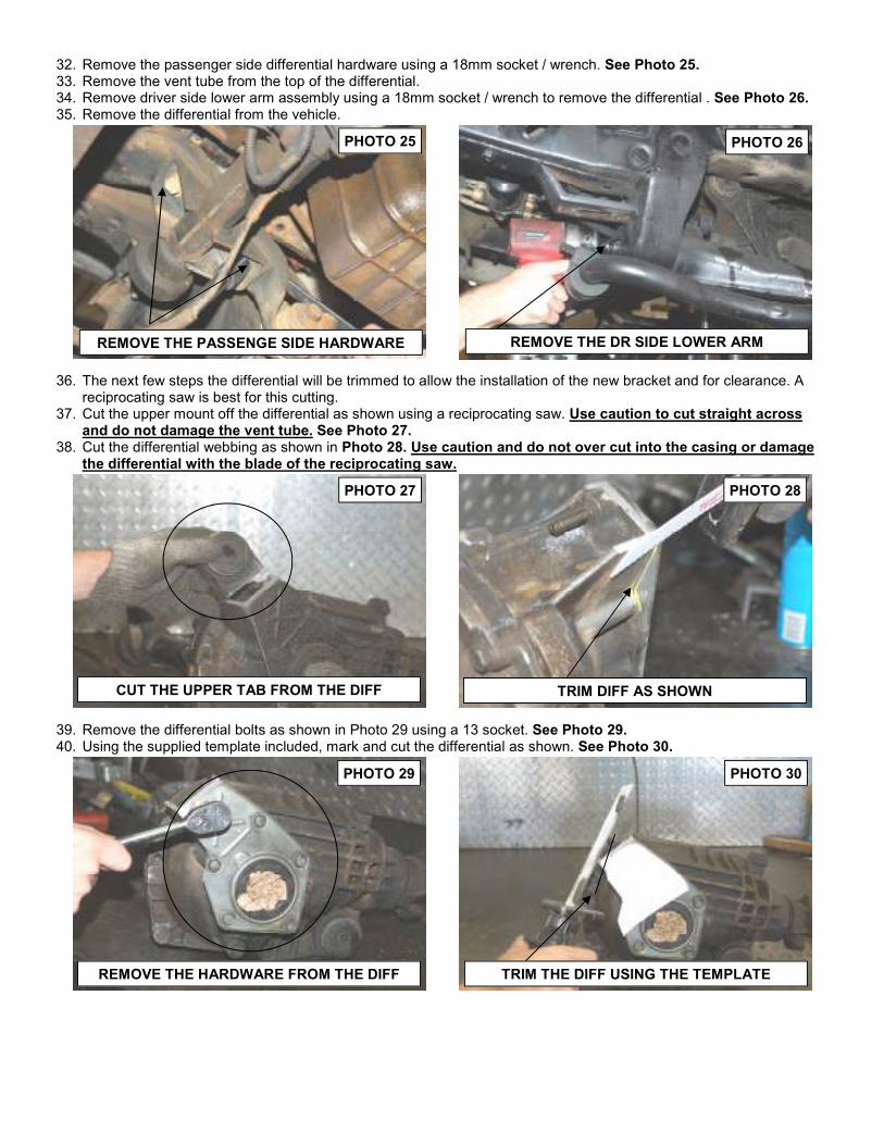
32. Remove the passenger side differential hardware using a 18mm socket / wrench. See Photo 25. 33. Remove the vent tube from the top of the differential. 34. Remove driver side lower arm assembly using a 18mm socket / wrench to remove the differential . See Photo 26. 35. Remove the differential from the vehicle.
36. The next few steps the differential will be trimmed to allow the installation of the new bracket and for clearance. A reciprocating saw is best for this cutting.
37. Cut the upper mount off the differential as shown using a reciprocating saw. Use caution to cut straight across and do not damage the vent tube. See Photo 27.
38. Cut the differential webbing as shown in Photo 28. Use caution and do not over cut into the casing or damage the differential with the blade of the reciprocating saw.
39. Remove the differential bolts as shown in Photo 29 using a 13 socket. See Photo 29. 40. Using the supplied template included, mark and cut the differential as shown. See Photo 30.
REMOVE THE PASSENGE SIDE HARDWARE
CUT THE UPPER TAB FROM THE DIFF
REMOVE THE HARDWARE FROM THE DIFF TRIM THE DIFF USING THE TEMPLATE
PHOTO 25 PHOTO 26
PHOTO 27 PHOTO 28
PHOTO 29 PHOTO 30
REMOVE THE DR SIDE LOWER ARM
TRIM DIFF AS SHOWN
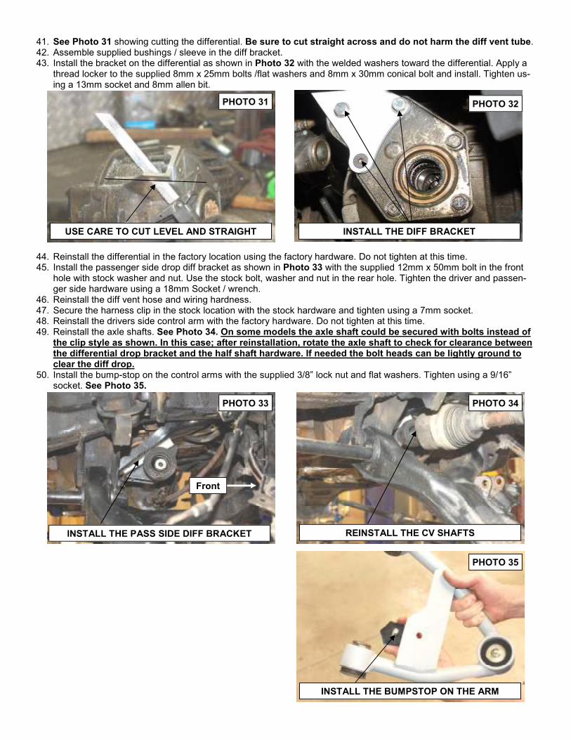
41. See Photo 31 showing cutting the differential. Be sure to cut straight across and do not harm the diff vent tube. 42. Assemble supplied bushings / sleeve in the diff bracket. 43. Install the bracket on the differential as shown in Photo 32 with the welded washers toward the differential. Apply a
thread locker to the supplied 8mm x 25mm bolts /flat washers and 8mm x 30mm conical bolt and install. Tighten us-ing a 13mm socket and 8mm allen bit.
44. Reinstall the differential in the factory location using the factory hardware. Do not tighten at this time. 45. Install the passenger side drop diff bracket as shown in Photo 33 with the supplied 12mm x 50mm bolt in the front
hole with stock washer and nut. Use the stock bolt, washer and nut in the rear hole. Tighten the driver and passen-ger side hardware using a 18mm Socket / wrench.
46. Reinstall the diff vent hose and wiring hardness. 47. Secure the harness clip in the stock location with the stock hardware and tighten using a 7mm socket. 48. Reinstall the drivers side control arm with the factory hardware. Do not tighten at this time. 49. Reinstall the axle shafts. See Photo 34. On some models the axle shaft could be secured with bolts instead of
the clip style as shown. In this case; after reinstallation, rotate the axle shaft to check for clearance between the differential drop bracket and the half shaft hardware. If needed the bolt heads can be lightly ground to clear the diff drop.
50. Install the bump-stop on the control arms with the supplied 3/8” lock nut and flat washers. Tighten using a 9/16” socket. See Photo 35.
Front
USE CARE TO CUT LEVEL AND STRAIGHT
INSTALL THE PASS SIDE DIFF BRACKET
PHOTO 31 PHOTO 32
PHOTO 33 PHOTO 34
PHOTO 35
REINSTALL THE CV SHAFTS
INSTALL THE DIFF BRACKET
INSTALL THE BUMPSTOP ON THE ARM
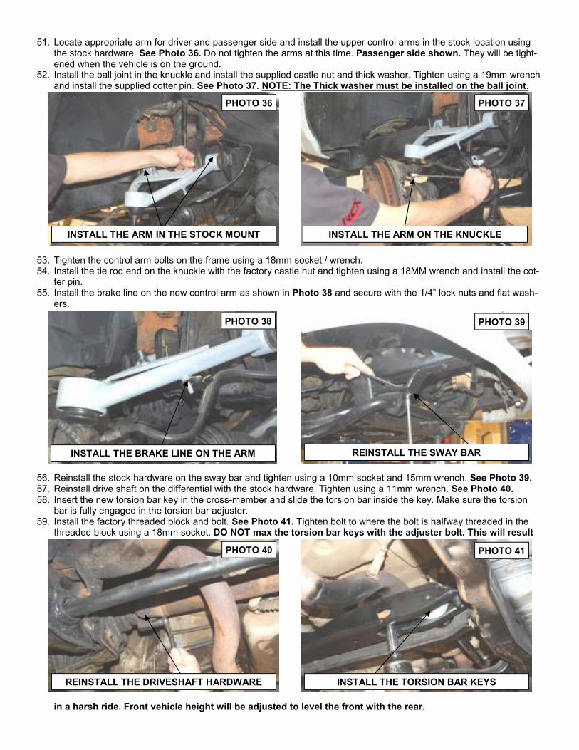
51. Locate appropriate arm for driver and passenger side and install the upper control arms in the stock location using the stock hardware. See Photo 36. Do not tighten the arms at this time. Passenger side shown. They will be tight-ened when the vehicle is on the ground.
52. Install the ball joint in the knuckle and install the supplied castle nut and thick washer. Tighten using a 19mm wrench and install the supplied cotter pin. See Photo 37. NOTE: The Thick washer must be installed on the ball joint.
53. Tighten the control arm bolts on the frame using a 18mm socket / wrench. 54. Install the tie rod end on the knuckle with the factory castle nut and tighten using a 18MM wrench and install the cot-
ter pin. 55. Install the brake line on the new control arm as shown in Photo 38 and secure with the 1/4” lock nuts and flat wash-
ers.
56. Reinstall the stock hardware on the sway bar and tighten using a 10mm socket and 15mm wrench. See Photo 39. 57. Reinstall drive shaft on the differential with the stock hardware. Tighten using a 11mm wrench. See Photo 40. 58. Insert the new torsion bar key in the cross-member and slide the torsion bar inside the key. Make sure the torsion
bar is fully engaged in the torsion bar adjuster. 59. Install the factory threaded block and bolt. See Photo 41. Tighten bolt to where the bolt is halfway threaded in the
threaded block using a 18mm socket. DO NOT max the torsion bar keys with the adjuster bolt. This will result
in a harsh ride. Front vehicle height will be adjusted to level the front with the rear.
INSTALL THE ARM ON THE KNUCKLE
INSTALL THE BRAKE LINE ON THE ARM REINSTALL THE SWAY BAR
PHOTO 36 PHOTO 37
PHOTO 38 PHOTO 39
PHOTO 40 PHOTO 41
INSTALL THE ARM IN THE STOCK MOUNT
REINSTALL THE DRIVESHAFT HARDWARE INSTALL THE TORSION BAR KEYS
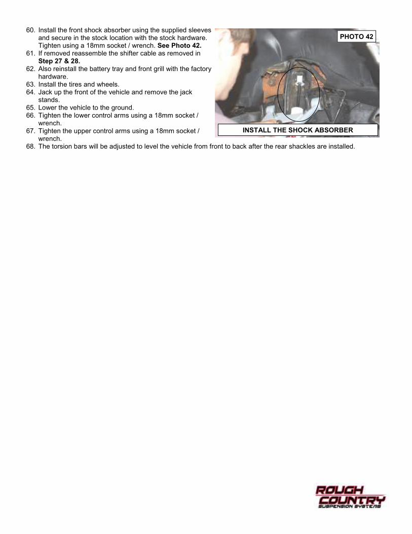
60. Install the front shock absorber using the supplied sleeves and secure in the stock location with the stock hardware. Tighten using a 18mm socket / wrench. See Photo 42.
61. If removed reassemble the shifter cable as removed in Step 27 & 28.
62. Also reinstall the battery tray and front grill with the factory hardware.
63. Install the tires and wheels. 64. Jack up the front of the vehicle and remove the jack
stands. 65. Lower the vehicle to the ground. 66. Tighten the lower control arms using a 18mm socket /
wrench. 67. Tighten the upper control arms using a 18mm socket /
wrench. 68. The torsion bars will be adjusted to level the vehicle from front to back after the rear shackles are installed.
INSTALL THE SHOCK ABSORBER
PHOTO 42
REAR INSTALLATION INSRUCTIONS
1. Chock front wheels to prevent any possibility of movement. 2. Position a floor jack under the center of the rear axle and raise the vehicle. 3. Place jack stands under the frame rails just in front of the spring hangers. Lower truck onto jack stands. Remove
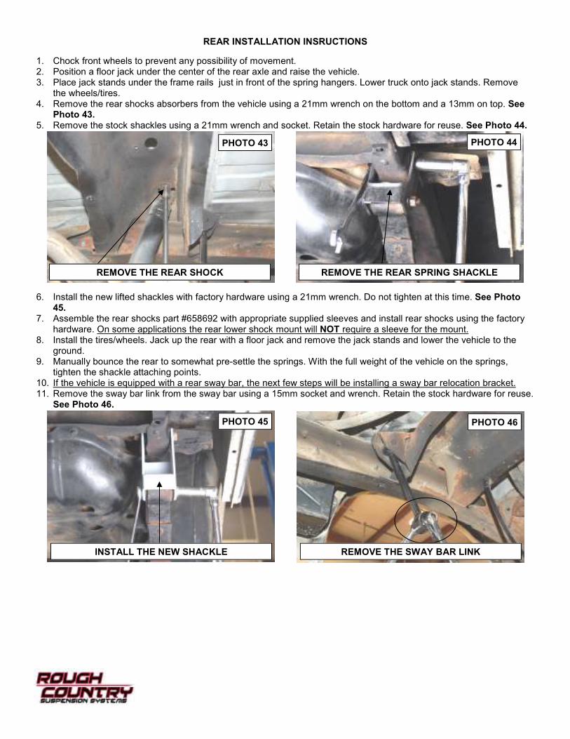
the wheels/tires. 4. Remove the rear shocks absorbers from the vehicle using a 21mm wrench on the bottom and a 13mm on top. See
Photo 43. 5. Remove the stock shackles using a 21mm wrench and socket. Retain the stock hardware for reuse. See Photo 44.
6. Install the new lifted shackles with factory hardware using a 21mm wrench. Do not tighten at this time. See Photo 45.
7. Assemble the rear shocks part #658692 with appropriate supplied sleeves and install rear shocks using the factory hardware. On some applications the rear lower shock mount will NOT require a sleeve for the mount.
8. Install the tires/wheels. Jack up the rear with a floor jack and remove the jack stands and lower the vehicle to the ground.
9. Manually bounce the rear to somewhat pre-settle the springs. With the full weight of the vehicle on the springs, tighten the shackle attaching points.
10. If the vehicle is equipped with a rear sway bar, the next few steps will be installing a sway bar relocation bracket. 11. Remove the sway bar link from the sway bar using a 15mm socket and wrench. Retain the stock hardware for reuse.
See Photo 46.
PHOTO 43 PHOTO 44
PHOTO 45 PHOTO 46
REMOVE THE REAR SHOCK REMOVE THE REAR SPRING SHACKLE
INSTALL THE NEW SHACKLE REMOVE THE SWAY BAR LINK
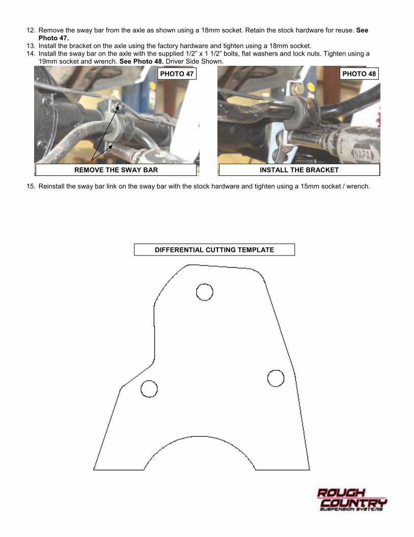
12. Remove the sway bar from the axle as shown using a 18mm socket. Retain the stock hardware for reuse. See Photo 47.
13. Install the bracket on the axle using the factory hardware and tighten using a 18mm socket. 14. Install the sway bar on the axle with the supplied 1/2” x 1 1/2” bolts, flat washers and lock nuts. Tighten using a
19mm socket and wrench. See Photo 48. Driver Side Shown.
15. Reinstall the sway bar link on the sway bar with the stock hardware and tighten using a 15mm socket / wrench.
REMOVE THE SWAY BAR INSTALL THE BRACKET
PHOTO 47 PHOTO 48
DIFFERENTIAL CUTTING TEMPLATE
MAINTENANCE INFORMATION
• If adjustment of the front end is needed. Jack up the front of the vehicle and adjust the torsion bar bolts to desired
height.
• Have vehicle aligned to factory specifications and adjust headlights.
• It is the ultimate buyers responsibility to have all bolts/nuts checked for tightness after the first 100 miles and then
every 1000 miles. Wheel alignment steering system, suspension and driveline systems must be inspected by a qualified professional mechanic at least every 3000 miles
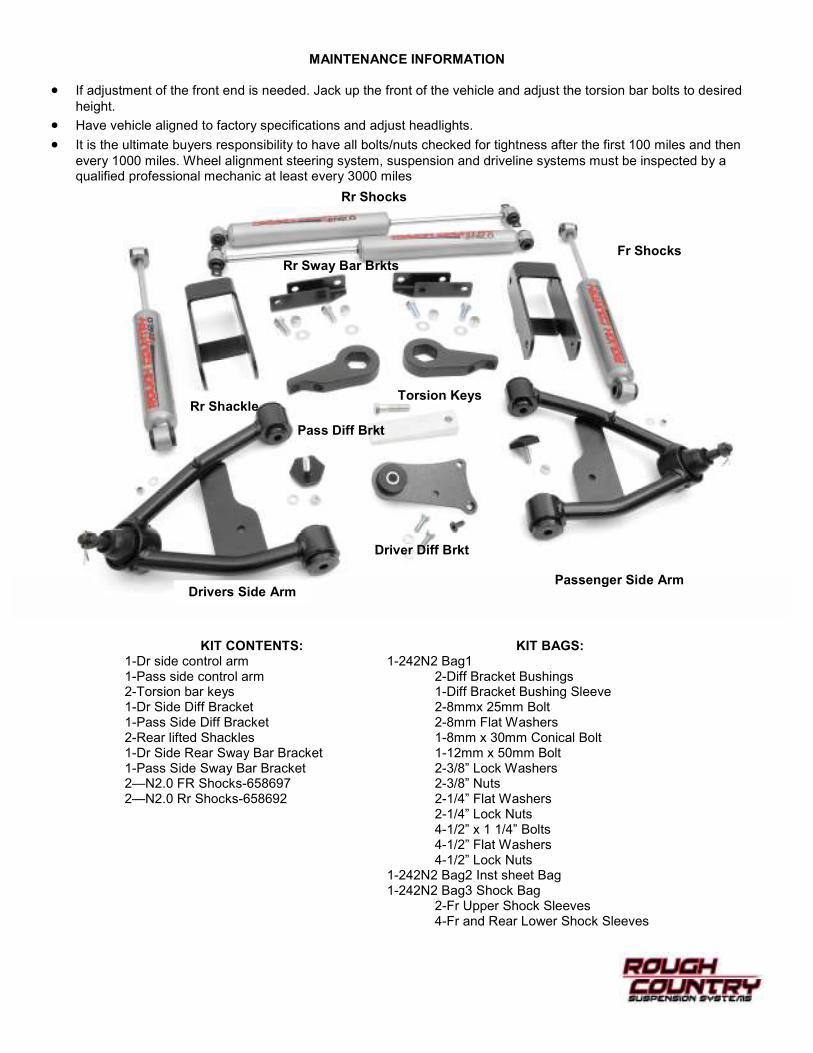
KIT CONTENTS: 1-Dr side control arm 1-Pass side control arm 2-Torsion bar keys 1-Dr Side Diff Bracket 1-Pass Side Diff Bracket 2-Rear lifted Shackles 1-Dr Side Rear Sway Bar Bracket 1-Pass Side Sway Bar Bracket 2—N2.0 FR Shocks-658697 2—N2.0 Rr Shocks-658692
KIT BAGS: 1-242N2 Bag1 2-Diff Bracket Bushings 1-Diff Bracket Bushing Sleeve 2-8mmx 25mm Bolt 2-8mm Flat Washers 1-8mm x 30mm Conical Bolt 1-12mm x 50mm Bolt 2-3/8” Lock Washers 2-3/8” Nuts 2-1/4” Flat Washers 2-1/4” Lock Nuts 4-1/2” x 1 1/4” Bolts 4-1/2” Flat Washers 4-1/2” Lock Nuts 1-242N2 Bag2 Inst sheet Bag 1-242N2 Bag3 Shock Bag 2-Fr Upper Shock Sleeves 4-Fr and Rear Lower Shock Sleeves
Drivers Side Arm Passenger Side Arm
Driver Diff Brkt
Pass Diff Brkt
Torsion Keys
Rr Sway Bar Brkts
Rr Shackle
Rr Shocks
Fr Shocks