8.1 fittings for lightweight boards - hettich · fittings for lightweight boards 8.1.3 fittings for...
TRANSCRIPT

Programme overview Group 8 8.0.1
Programme overviewGroup 8
8.1 Fittings for lightweight boards
Range summary 8.1.0i
8.2 Connecting fittings
Range summary 8.2.0 - 8.2.1i
8.3 Fittings for beds and upholstered furniture
Range summary 8.3.1i
8.4. Height adjustable legs
Range summary 8.4.1i
8.5 Shelf supports and shelf-support strips/folding support brackets
Range summary 8.5.1i
8.6 Cabinet suspension brackets
Range summary 8.6.1i
8.7. Furniture glides/Buffers/Furniture levelling wedges8.7.0 - 8.7.1

Range summary8.1 Fittings for lightweight boards
Fittings for lightweight boards www.hettich.com8.1.0
Turning ideas into lightweight reality
8.1.2 - 8.1.4
Lightweight construction is up-and-coming
8.1.5
Fastening fittings tolightweight boards
8.1.7
hettinject glued dowel/plastic knock-in socket no. 4 HT
8.1.8 - 8.1.10
Worktop connector AVB HTfor lightweight boards
8.1.12
Information on machining lightweight boards
8.1.13
The lighter side of success
8.1.1
Types and structure oflightweight boards
8.1.6
Connecting fittingsfor lightweight boards
8.1.11
i

Fittings for lightweight boards 8.1.1
Fittings for lightweight boards
Lightweight material, fascinating furniture. Lightweight boards aresetting new standards in furniture construction and interior design. Unusual design defines this generation of high-quality furniture forhome living.
Innovative designs open up new potential and markets. Lightweightconstruction is more than a trend. It ensures economy and efficiency. With prices for raw materials, energy and transport constantly rising,less is more.
The lighter side of success

Fittings for lightweight boards
Fittings for lightweight boards www.hettich.com8.1.2
The new, lighter home
The use of lightweight boards is opening up new possibilities in the living room andbedroom – with a particular focus on:• Thick-walled cabinet designs• Large-surface sliding doors
Dream kitchens, refreshingly light
In the kitchen, end-panelsystems connected to worktopsform the focus. The lightweightboard is an innovative solution,particularly for large-surface,cantilevered kitchen worktops.
Turning ideas into lightweight reality

Fittings for lightweight boards 8.1.3
Fittings for lightweight boards
Practical and lightweight for the most exacting of demands
Exhibition stand construction, shopfitting and interiordesign are predestined for applications using lightweightsolutions. This is where the material's weight advantagereally pays its dividends. In this segment, the cost oftransport and assembly are particularly high.
Whether for exhibition stands, shopfitting or wall elements for interior fittings – high-quality, practicaldesigns are easy to produce with lightweight solutions.

Fittings for lightweight boards
Fittings for lightweight boards www.hettich.com8.1.4
An air of lightness in modern office landscape
The benefits of the lightweight board once again comeinto their own in constructing conference tables and desks.The significant reduction in weight takes the effort outof constructing even unusual designs.
In addition, the lightweight board permits significantlylarger spans with less sag than in the case of conventional boards.Even trendy shelf solutions with thick end panelsare easily designed and, at the same time, easy and simple to handle.

Fittings for lightweight boards 8.1.5
Fittings for lightweight boards
Modern, economic, contemporary
With lightweight construction,room design has never been morevariable. Whether shelf systems, hingeddoors, sliding doors, cabinet components, tables or worktops – lightweight constructions are creating a new, attractive home-living style and offer somehuge advantages.
Ergonomics/weight
• Low material weight• Reduced shipping costs• Easier assembly and disassembly• Ease of handling – especially
when it comes to mobile furniture
Careful use of resources
• Efficient use of wood• Optimised use of energy in
production and transportation• Efficient utilisation of transport
volumes
Broad application spectrum in
• Kitchens/bathrooms• Living rooms/bedrooms• Offices/hotels• Exhibition stand construction/
shopfitting/interior design• Boat/caravan construction
Material properties
• High stability• Optimum bending strength• Large spans• Ease of use
Design freedom with new possibilities in
• Dimension• Material thickness• Format
Lightweight construction is up-and-coming

Fittings for lightweight boards
Fittings for lightweight boards www.hettich.com8.1.6
Lightweight boards without frame
Surface layerHoneycomb core
Frame
Lightweight boards with frame
Types and structure of lightweight boards
Surface layerHoneycomb core

Fittings for lightweight boards 8.1.7
Fittings for lightweight boards
Surface layer 4 mm
Fastening fittings to lightweight boardsFastening fittings to lightweight boardswithout frame and 4 mm surface layer mustbe done using hardware suitable for this purpose. These options are available
• hettinject glued dowel or• Plastic socket no. 4 HT
For details, see 8.1.8 - 8.1.10
Fastening standard fittings to lightweightboards without frame and 8 mm surfacelayer is done in the familiar way using chipboard or direct fixing screws in a similarmanner to furniture made of solid chipboard. We recommend the use of the hettinjectglued dowel for fittings exposed to highstress and strain.
Fastening standard fittings to lightweightboards with frame and 8 mm surface layer isdone in the familiar way using chipboard ordirect fixing screws in a similar manner tofurniture made of solid chipboard. We recommend the use of the hettinjectglued dowel for fittings exposed to highlevels of stress and strain.
When fastening hardware to lightweightboards with frame and 4 mm surface layer, a distinction must be drawn between framezone and frameless zone:
Frame zone: Fastening by means of chipboard or direct fixing screws
Frameless zone: Fastening with
• hettinject glued dowel or• Plastic socket no. 4 HT
For details, see 8.1.8 - 8.1.10
4
8
4
8
Surface layer 8 mm
Surface layer 4 mm
Surface layer 8 mm

Glued dowel system for any form of lightweight board
Furniture constructed from frameless lightweight boardswith surface layers of only 4 mm require a hardware solutionthat also provides enough strength to withstand high loadswhen bridging the cavity inside the board.
The hettinject glued dowel channels an injected adhesivethrough to the top and bottom surface layer, joining themboth to create a highly sturdy structure capable of taking upboth tensile and compressive forces.
hettinject – the new fastening system
Fittings for lightweight boards
Fittings for lightweight boards www.hettich.com8.1.8

Fittings for lightweight boards 8.1.9
Fittings for lightweight boards
hettinject is an injection system with plenty ofstrength to spare. The forward-looking method guarantees highpull-out resistance and achieves extremely highlevels of strength.
The graph below shows a comparison of the pull-outstrengths achieved for various fixings in lightweightboards with a 4 and an 8 mm surface layer. The 6,3 mm dia. direct connector screw serves as a reference to solid chipboard.
Outstanding test results
Pull-out strengths in lightweight boards with a 4 mm surface layer
Pull-out strengths in lightweight boards with an 8 mm surface layer
Use not recommended in lightweight boards250
500
750
1000
1250
N
� �
�
Use recommended in lightweight boards
4 84 8
When securing fittings which are subject to littlestress (so-called idle or static loads), the plasticknock-in socket No. 4 HT supplements thehettinject adhesive dowel for 4 mm top layers.
This can e.g. be used for fastening shelf supports,wardrobe rail supports or back panel connectors to any position on the honeycomb board with 6,3 mm dia. direct fixing screws.
� Direct connector screws 260 - 300 N� Special screw for lightweight boards 270 - 310 N� Hettich socket no. 4 HT 300 - 400 N� hettinject glued dowel 650 - 850 N
� Special screw for lightweight boards 620 - 720 N� hettinject glued dowel 750 - 1250 N
Tests relate to honeycomb boards with a surface layer comparable to chipboard conforming to DIN EN 312 with a gross density to DIN EN 323.
The tear-out values of fastening material can be strongly effected by the nature and quality of the light weight panels used as well as the manufacturing tolerances. Therefore the application of the selected fastening material needs to be verified from cast to case.
Pull-out strengths for a direct connector screw in 19 mm solid chipboard 600 - 700 N
�
�
�

Fittings for lightweight boards
Fittings for lightweight boards www.hettich.com8.1.10
In addition to machining, the hettinject method also provides the capability of fitting the glued dowel by hand.
Procedure:
1. Drilling the board 2. Clearing the drill hole
3. Fitting the hettinject glued dowel 4. Injecting the adhesive
5. The end of the injection process shown by the change in colour
6. The fittings can be mounted once the adhesive has set

Fittings for lightweight boards 8.1.11
Fittings for lightweight boards
The VB 36 HT is suitable for corner connections with lightweight boards with surface layers of 3 mm and over.This connecting fitting features a special expanding housing that is firmly anchored after knocking in an additional expanding pin below the top surface layer.The tried and tested eccentric latching principle ensuresthat the dowel engages and pulls tight in the fitting.
Optionally, the VB 36 HT is equipped with a torquesupport. A web ensures that the dowel is securelyheld in the housing, thus holding the cabinet components together, before tightening the eccentric cam.
Web
Worktop connector AVB HT
As the high-strength answer to connecting worktops,the AVB HT complements the range for 50 and 60 mmlightweight boards with surface layers of 8 mm.
Simply inserted in two 40 mm drill holes, the two sections are braced together quickly and convenientlyfrom below by means of a 90° deflection gear – eitherwith an Allen key or, if speed is important, with a cordless screwdriver.
Securely anchored

Fittings for lightweight boards
Fittings for lightweight boards www.hettich.com8.1.12
Worktop connectors AVB HT
• For sturdy, positive-fitting and friction-lockedconnections between lightweight worktops
• For Worksop thicknesses of 50 and 60 mm• Suitable for use with 8 mm surface layers• Housing drill hole ø 40 mm• Drilling depth 46 or 56 mm• An 90° angle gear with hexagon socket
integrated in the plastic housing permits fast,convenient bracing with cordless screwdriver
• Chromated steel/black plastic
Assembly
Length Dimension X Worktop thickness PUmm mm 50 mm 60 mm
65 33 - 44 9 079 567 9 080 216 1/20
100 49 - 61 9 079 570 9 080 217 1/20
150 75 - 86 9 079 571 9 080 218 1/20
4
8
ø40
13
50 / 60
X X
8 8
� ��
!

Fittings for lightweight boards 8.1.13
Fittings for lightweight boards
Machining
Sawing as solid chipboard, if possible with scorer(according to the specifications of the tool manufacturer)
Drill holes as solid chipboard, however with drill without centring point
Milling counter-rotating
Veneering and coating
Specific contact pressure according to the specifications of the lightweight board manufacturer
Edging
Lightweight board• With frame, surface layer 4 or 8 mm with decorative edge, as solid chipboard
• Without frame, surface layer 4 mm with supporting edge (for supporting surface layers one against theother as well as a base for applying the decorative edge)
• Without frame, surface layer 8 mm with decorative edge, as solid chipboard
Information on machining

Range summary8.2 Connecting fittings
Connecting fittings www.hettich.com8.2.0
Cam fitting Rastex 25
8.2.11 - 8.2.13
Cam fittingVB 18/19/20/21
8.2.14 - 8.2.17
Cam fittingStabilofix
8.2.25
Cam fittingVB 47
8.2.26
Block connecting fittings
8.2.29 - 8.2.30
Shelf connecting fittingsVB 54 Toolex/VB 135
8.2.31 - 8.2.34
Cam fitting Rastex 15
8.2.2 - 8.2.10
Cam fittingVB 35/35 M/36/36 M
8.2.18 - 8.2.24
Connecting fittingVB 25 T/35 T/45-90 T/90-180 T
8.2.27 - 8.2.28
i

Connecting fittings 8.2.1
Range summary8.2 Connecting fittings
Non-release connecting fittingEverfix
8.2.36 - 8.2.37
Clip connector MultiClip
8.2.38
Cornice connecting fitting VB 16Mitre connector VB 160
8.2.40
Back panel connectors
8.2.41 - 8.2.42
Angle connectors/connecting screwsKeyhole fittings
8.2.44 - 8.2.46
Screws, sockets, cone-shaped plugs
8.2.47 - 8.2.50
Worktop connectors
8.2.34 - 8.2.35
Angled connecting fittingVB 90
8.2.39
Front panel connectors
8.2.43
i

!
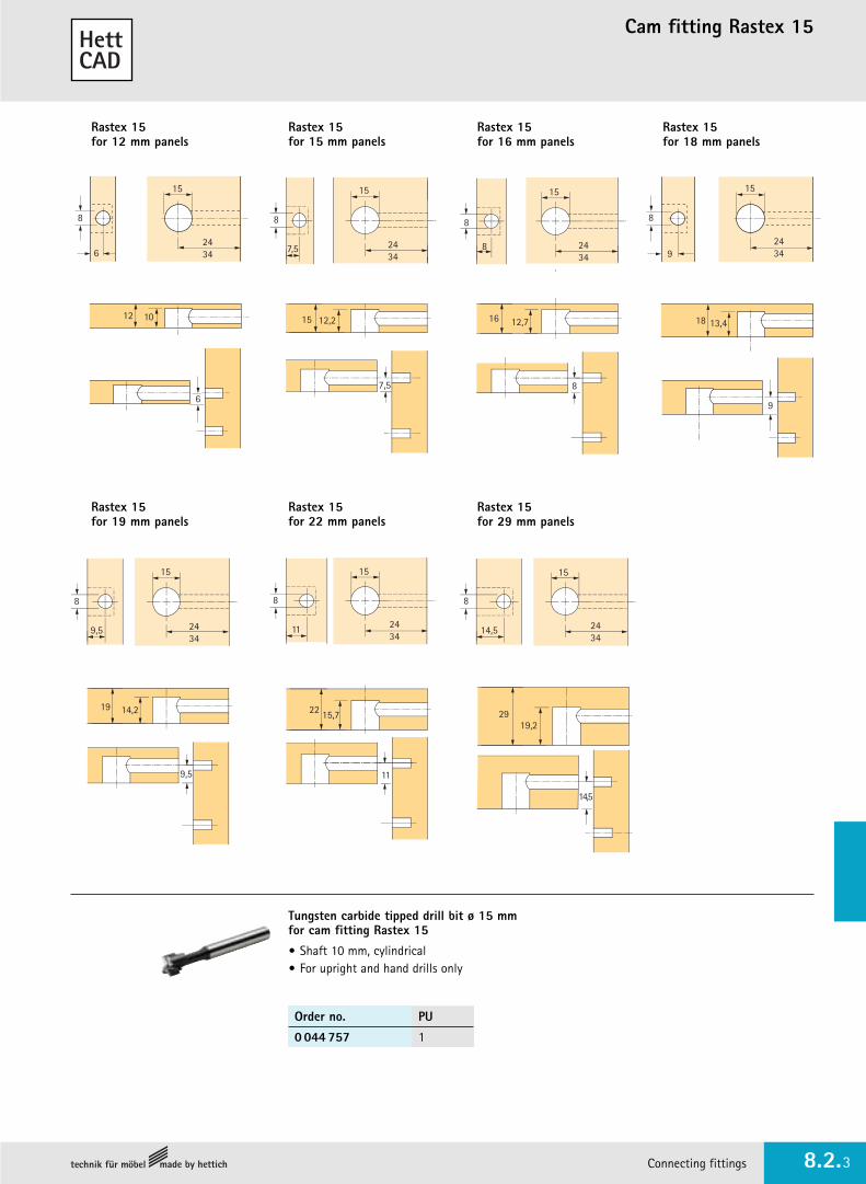
Cam fitting Rastex 15
Connecting fittings www.hettich.com8.2.2
• With torque support – allows furniture sides to be pulled into placefrom distances up to 4 mm from the panel end
• Twice as secure thanks to internal and external indentations –the dowel is always pulled in to the centred position, ruling out any displacement of furniture components.
• Cam can be tightened with a slot screwdriver or crossheadscrewdriver PZ 3 or Allen key SW 4
• The rim conceals rough drilling holes and an additional cover cap is not required
• Useable in 12, 15, 16, 18, 19, 22 or 29 mm panels• Die-cast zinc
� with rim � without rim
Cover caps for Rastex 15 without rim (except Rastex 15/12)
• Plastic
Finish for 12 mm for 15 mm for 16 mm for 18 mm PUpanels panels panels panels� � � � � �
nickel-plated 0 020 049 0 079 451 0 079 457 0 071 948 0 025 062 0 013 957 1/200
nickel-plated 0 020 050 0 079 452 0 079 458 0 073 459 0 073 456 0 013 958 2000
self-colour 0 020 053 0 079 455 0 079 461 0 079 464 0 079 466 0 013 961 1/200
self-colour 9 020 420 0 079 456 0 079 462 0 079 465 0 079 467 0 013 962 2000
Finish for 19 mm for 22 mm for 29 mm PUpanels panels panels� � � � � �
nickel-plated 0 071 950 0 025 064 0 071 952 0 025 066 0 079 478 0 079 484 1/200
nickel-plated 0 073 460 0 073 457 0 073 461 0 073 458 0 079 479 0 079 485 2000
self-colour 0 079 469 0 079 471 0 079 474 0 079 476 0 079 482 0 079 488 1/200
self-colour 0 079 470 0 079 472 0 079 475 0 079 477 0 079 483 0 079 489 2000
Finish Order no. PU
white 0 071 054 1/200
brown 0 071 055 1/200
black 0 079 490 1/200
pine 0 079 491 1/200
Dowels / sockets - see pages 8.2.4 - 8.2.10
Connecting fittings 8.2.3
Cam fitting Rastex 15
Rastex 15for 15 mm panels
Rastex 15for 16 mm panels
8
7,5
15
2434
2434
15
8
8
Rastex 15for 12 mm panels
15
8
62434
8
11
15
2434
15
8
14,5 2434
15
8
9,5 2434
15
8
92434
Rastex 15for 22 mm panels
Rastex 15for 29 mm panels
Rastex 15for 19 mm panels
Rastex 15for 18 mm panels
15 12,2
7,5 8
12,71612 10
6
18 13,4
9
19 14,2
9,5
22 15,7
11
22 15,7
Tungsten carbide tipped drill bit ø 15 mm for cam fitting Rastex 15
• Shaft 10 mm, cylindrical• For upright and hand drills only
2919,2
14,5
Order no. PU
0 044 757 1

Fast assembly dowel Rapid S
Connecting fittings www.hettich.com8.2.4
Fast - faster - Rapid S
New:extremely sturdy steel core
Edge ensures correctposition in carcase side
Colour coding for 8 and10 mm holes
Four expanding jaws foroptimum expansion
Thread prevents damage to the drill hole when unscrewing the dowel
• Fast, toolless installation, simplypresses by hand into the hole in thecarcase side
• Reduced costs from shorterassembly times
• The stable connection closes everygap and even accepts a tolerance in the eccentric drill hole of up to 1 mm without losing pull-outstrength.
• Easy to tell apart with colouredexpanding elements for 8 mm (blue)and 10 mm (green) drill holes
• For 8 mm ø and 10 mm ø side panel drill holes with a dowellength of 20 mm or 30 mm
The new generation of Hettich fast assembly dowels with a steelcore. Slimline, lightweight and incredibly strong. Fitted without theneed for tools – the dowel simply pushes into place. With Rastex, the Rapid S makes the perfect pair.

Connecting fittings 8.2.5
Fast assembly dowel Rapid S for Rastex 15Hole diameter 8 and 10 mm
10,520/30
ø8
Rapid SFast assembly dowel DU 324/DU 325
• Expanding socket for 8 mm hole diameter• Dowel length 20 mm/30 mm• Steel/blue plastic
11
24/34
ø8 ø8
ø10
Rapid SFast assembly dowel DU 332/DU 333
• Expanding socket for 10 mm hole diameter• Dowel length 20 mm/30 mm• Steel/green plastic
11
24/34
ø8ø10
10,520/30
Article Dowel length Order no. PUmm
Rapid S DU 324 20 0 044 750 1/200
Rapid S DU 325 30 0 047 458 1/200
Article Dowel length Order no. PUmm
Rapid S DU 332 20 0 044 758 1/200
Rapid S DU 333 30 0 044 759 1/200
1. Rapid S simply pushes into the drill holewith the press of a finger. The plasticdowel shank is non-slip – making it easyto press in.
2. Rastex 15 is pushed into the mounting hole.
3. On tightening the Rastex 15, the socketimmediately expands, significantlyincreasing pull-out strength. Bottom and side are joined together securely and reliably.

Screw-in dowel Twister
Connecting fittings www.hettich.com8.2.6
Dowel head with Pozidrive 2
Steel dowel
Coloured, freely turningplastic sleeve in easy-to-grip fluted design
Longitudinal rib continuesat the foot of the dowel
Euro screw or metric thread
Twister – quickly fitted without the risk of injuryBy holding the freely rotating sleeve, the Twister can be driven in all the way safely and reliablythroughout the insertion process with the cordless screwdriver – preventing risk of injury fromsharp edges or burrs.
The right dowel is always to hand
• Coloured plastic sleeves in easy-to-gripfluted design indicate dowel lengthsGreen ➔ 20 mm for Rastex 15Blue ➔ 24,5 mm for Rastex 25Black ➔ 30 mm for Rastex 15
• Direct fixing thread for System 32 hole lineswith a drilling diameter of 5 mm
• M6 x 7,8 mm metric thread for plastic or brass sockets
• Excellent torque transmission from drill bit to dowel head
• Chamfer at start of thread for easy insertion into drill hole
20 3024,5
Twister dowel lengths
Chamfer on thread tip

Connecting fittings 8.2.7
Screw-in dowel Twister /Sockets for Rastex 15Hole diameter 5, 8 and 10 mm
ø5
24/34
ø8 9
20/30 8,5
Twister Screw-in dowel DU 319/DU 320
• Euro screw thread for 5 mm hole diameter• Dowel length 20 mm/30 mm• Zinc-plated steel/green or black plastic
ø5
24/34
ø811,5
ø5
20/30 11
Twister Screw-in dowel DU 243/DU 232
• Euro screw thread for 5 mm hole diameter• Dowel length 20 mm/30 mm• Zinc-plated steel/green or black plastic
ø5
24/34
ø8 11,5
ø 8/10
Twister Screw-in dowel DU 645/DU 644
• Thread M6 x 7,8 mm• Dowel length 20 mm/30 mm• Zinc-plated steel/green or black plastic
20/30 7,8
M6
ø8/10
DU 645/DU 644 can be used with...
ø8
11
ø10
11
13
12
13
ø10
12
11
ø8
9/12
ø8
ø10ø8 ø10
ø10 ø10
Expanding socket with/without nylon ball• For thread M6• Hole diameter 8 mm• brass self-colour
Socket no. 49• For thread M6• Hole diameter
8 mm• White plastic
Socket no. 100• For thread M6• Hole diameter
10 mm• White plastic
Socket strip no. 1• For thread M6• Hole diameter 10 mm• 20 items per strip• White plastic
Length Order no. PU
9 mm without nylon ball 0 079 537 1/200
12 mm with nylon ball 0 079 538 1/200
Order no. PU
0 079 540 1/200
Order no. PU
0 040 005 1/200
Order no. PU
0 079 539 1/200
Order no. PU
0 079 541 1/200
Order no. PU
0 079 542 1/200
Socket no. 33• For thread M6• Hole diameter
10 mm• White plastic
Socket strip no. 330• For thread M6• Hole diameter 10 mm• 20 items per strip• White plastic
Drilling jig Accura 32 for System 32 and dowel drilling – see group 2
Article Dowel length Order no. PUmm
Twister DU 319 20 0 048 037 1/200
Twister DU 320 30 0 048 038 1/200
Article Dowel length Order no. PUmm
Twister DU 243 20 0 020 056 1/200
Twister DU 232 30 0 020 058 1/200
Article Dowel length Order no. PUmm
Twister DU 645 20 0 020 155 1/200
Twister DU 644 30 0 020 157 1/200

Dowels/sockets for Rastex 15Hole diameter 5, 6, 8 and 10 mm
Connecting fittings www.hettich.com8.2.8
8
ø5/6/8/10
24/34
ø8
Screw-in dowel DU 428/DU 425
• Thread M4 x 7,8 mm• Dowel length 20 mm/30 mm• Steel
ø5
DU 428/DU 425 can be used with...
*Threaded sleeve • For thread M4• Hole diameter 5 mm• Chromated steel
LL
9M4
End screw
• Thread M4• For use with threaded sleeve M4*• Nickel-plated steel
ø5/6
7,8 ø8
8
Socket no. 30
• For thread M4• Hole diameter 8 mm• White plastic
ø10
10
Socket no. 74
• For thread M4• Hole diameter 10 mm• White plastic
Expanding socket
• For thread M4• Hole diameter 5 or 6 mm• Brass self-colour ø5
ø6
ø8 ø10
Drilling jig Accura 32 for System 32 and dowel drilling – see group 2.3
20/30 7,8
M4
ø5/6/8/10
Hole diameter mm Order no. PU
5 0 048 578 1/200
6 0 065 541 1/200
Length L mm Order no. PU
8 0 079 525 200
9 0 079 527 200
Length L mm Order no. PU
15 0 063 016 1/200
18 0 064 908 1/200
22 0 063 017 1/200
Order no. PU
0 079 529 1/200
Order no. PU
0 079 530 1/200
Article Finish Dowel length Order no. PUmm
DU 428 self-colour 20 0 079 523 1/200
chrome-plated 20 0 079 524 1/200
DU 425 self-colour 30 0 079 521 1/200
chrome-plated 30 0 079 522 1/200
!
Connecting fittings 8.2.9
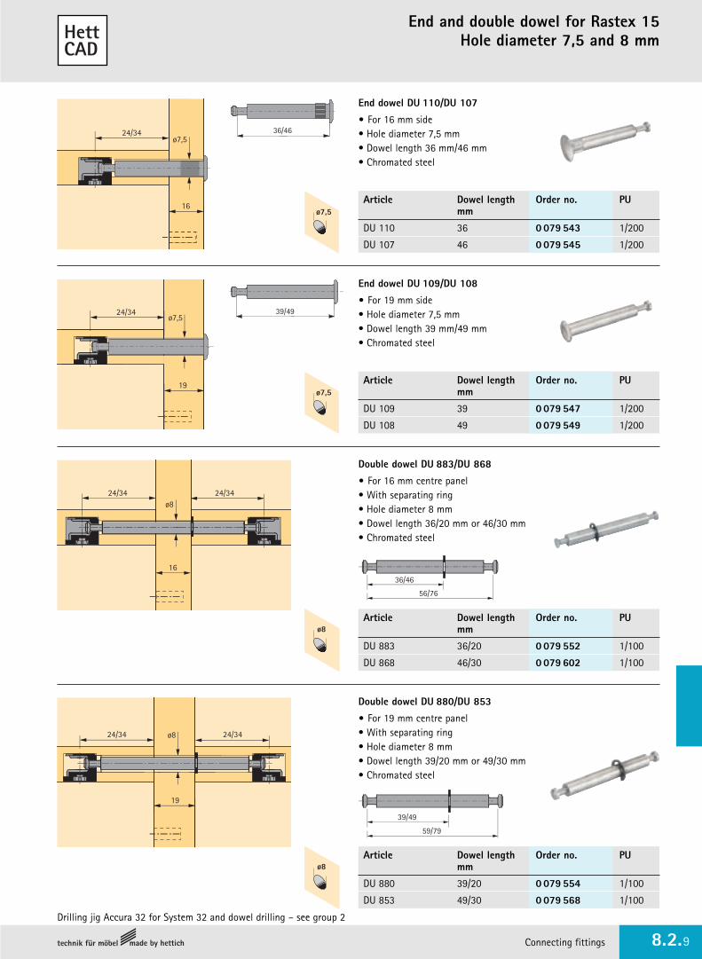
End and double dowel for Rastex 15Hole diameter 7,5 and 8 mm
16
ø7,524/34
End dowel DU 110/DU 107
• For 16 mm side• Hole diameter 7,5 mm• Dowel length 36 mm/46 mm• Chromated steel
ø7,5
36/46
19
ø7,524/34
End dowel DU 109/DU 108
• For 19 mm side• Hole diameter 7,5 mm• Dowel length 39 mm/49 mm• Chromated steel
ø7,5
39/49
24/34
16
ø824/34
Double dowel DU 883/DU 868
• For 16 mm centre panel• With separating ring• Hole diameter 8 mm• Dowel length 36/20 mm or 46/30 mm• Chromated steel
ø7,5
36/46
56/76
ø8
24/34 ø8
19
24/34
Double dowel DU 880/DU 853
• For 19 mm centre panel• With separating ring• Hole diameter 8 mm• Dowel length 39/20 mm or 49/30 mm• Chromated steel
ø7,5
59/79
39/49
ø8
Drilling jig Accura 32 for System 32 and dowel drilling – see group 2
Article Dowel length Order no. PUmm
DU 110 36 0 079 543 1/200
DU 107 46 0 079 545 1/200
Article Dowel length Order no. PUmm
DU 109 39 0 079 547 1/200
DU 108 49 0 079 549 1/200
Article Dowel length Order no. PUmm
DU 883 36/20 0 079 552 1/100
DU 868 46/30 0 079 602 1/100
Article Dowel length Order no. PUmm
DU 880 39/20 0 079 554 1/100
DU 853 49/30 0 079 568 1/100

Angle dowel for Rastex 15Hole diameter 5, 8 and 10 mm
Connecting fittings www.hettich.com8.2.10
24/44
24/44
ø7
X
α
Angle dowel DU 885/DU 860
• 90º - 180º adjustable• Hole diameter 7 mm• Dowel length 20/20 mm or 39/39 mm• Chromated steel
20/39
20/39
ø7
ø8
15
ø7
24/44
α
x
Angle dowel DU 650/DU 634
• Thread M6 x 7 mm• Hole diameter 8 mm• Dowel length 20 mm/39 mm• Chromated steel
Threaded sockets M6 – see page 8.2.7
20/39
ø8/10
For angle dowels DU 650/DU 885, drilling distance X is calculated: X = above values in table - 20
Drilling distance X for angle dowels DU 634/DU 860.
Angle Panel thicknessα 15 16 19 22 29
Drilling distance X mmfor DU 634
30° 57,0 57,9 60,5 63,1 69,1
35° 54,7 55,4 57,6 59,7 64,7
40° 52,9 53,5 55,3 57,1 61,3
45° 51,5 52,0 53,5 55,0 58,5
50° 50,3 50,7 52,0 53,2 56,2
55° 49,3 49,6 50,7 51,7 54,2
60° 48,3 48,6 49,5 50,4 52,4
65° 47,5 47,7 48,4 49,1 50,8
70° 46,7 46,9 47,5 48,0 49,3
75° 46,0 46,1 46,5 46,9 47,9
80° 45,3 45,4 45,7 45,9 46,6
85° 44,7 44,7 44,8 45,0 45,3
90° 44,0 44,0 44,0 44,0 44,0
Angle Panel thicknessα 15 16 19 22 29
Drilling distance X mmfor DU 860
100° 37,7 37,3 36,0 34,8 31,8
105° 38,2 37,9 36,7 35,6 32,9
110° 38,7 38,4 37,3 36,3 33,9
115° 39,2 38,9 37,9 37,0 35,8
120° 39,7 39,4 38,5 37,7 35,6
125° 40,1 39,8 39,1 38,3 36,5
130° 40,5 40,3 39,6 38,9 37,7
135° 40,9 40,7 40,1 39,4 38,0
140° 41,3 41,1 40,5 40,0 38,7
145° 41,6 41,5 41,0 40,5 39,4
150° 42,0 41,9 41,5 41,1 40,1
155° 42,3 42,2 41,9 41,6 40,8
160° 42,7 42,6 42,3 42,1 41,4
Article Dowel length Order no. PUmm
DU 885 20/20 0 079 579 1/100
DU 860 39/39 0 079 580 1/100
Article Dowel length Order no. PUmm
DU 650 20 0 079 570 1/100
DU 634 39 0 079 571 1/100!

Connecting fittings 8.2.11
Cam fitting Rastex 25
• Double safety provided by interior and exterior indentation• Indentations, both inside and out, prevent accidental loosening
of the cam• The reverse torque is three times greater than with comparable
cam fittings• The dowel is always tightened centrally• No more loosening due to vibration during transport• Rastex 25 with and without rim• Die-cast zinc
8
12
A (33,5)7
7
ø25
Drilling pattern for panels
Dowel centre fromunderside of panel
Hole distance A =Dowel length + 9 mm
Interior and exterior indentation -double security!
Cover caps for Rastex 25
• Plastic
Article Finish Order no. PU
Rastex 25
with rim nickel-plated 0 079 695 1/200
without rim self-colour 0 013 116 1/200
Tungsten carbide tipped drill bit ø 25 mmfor cam fitting Rastex 25
• Shaft 10 mm, cylindrical• For upright and hand drills only
Order no. PU
0 046 074 1
Hole diameter mm Order no. PU
white 0 013 117 1/200
brown 0 013 118 1/200
light oak 0 025 056 1/200
black 0 070 711 1/200
Dowels / sockets - see pages 8.2.12 – 8.2.13

Dowels for Rastex 25Hole diameter 5 and 8 mm
Connecting fittings www.hettich.com8.2.12
ø8
ø8
33,5
ø811,5
ø5
Twister Screw-in dowel DU 262
• Euro screw thread for 5 mm hole diameter• Dowel length 24,5 mm• Galvanized steel/blue plastic
ø8
1933,5
End dowel DU 960
• For 19 mm side• Hole diameter 8 mm• Dowel length 43,5 mm• Nickel-plated steel
ø8
1933,5 33,5
Double dowel DU 826
• For 19 mm centre panel• With separating ring• Hole diameter 8 mm• Dowel length 43,5/24,5 mm• Steel self-colour
43,5
6843,5
ø5
24,5 11
Order no. PU
0 020 060 1/200
Order no. PU
0 047 695 1/200
Order no. PU
0 047 692 1/100
Drilling jig Accura 32 for System 32 and dowel drilling – see group 2
Socket no. 100
• For thread M6• Hole diameter 10 mm• White plastic
Socket strip no. 330
• For thread M6• Hole diameter 10 mm• 20 items per strip• White plastic
Connecting fittings 8.2.13
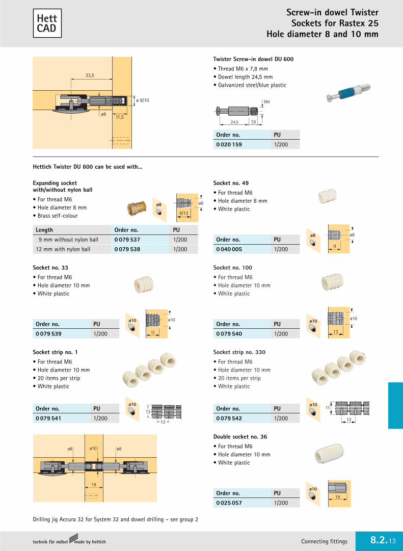
Screw-in dowel TwisterSockets for Rastex 25
Hole diameter 8 and 10 mm
Drilling jig Accura 32 for System 32 and dowel drilling – see group 2
33,5
ø8 11,5
ø 8/10
Twister Screw-in dowel DU 600
• Thread M6 x 7,8 mm• Dowel length 24,5 mm• Galvanized steel/blue plastic
24,5 7,8
M6
19
Double socket no. 36
• For thread M6• Hole diameter 10 mm• White plastic
ø10
19
ø8ø8
Hettich Twister DU 600 can be used with...
ø8
11
ø10
11 13
ø10
12
11
ø8
9/12
ø8
ø8
ø10 ø10
ø10
Expanding socket with/without nylon ball
• For thread M6• Hole diameter 8 mm• Brass self-colour
Socket no. 49
• For thread M6• Hole diameter 8 mm• White plastic
Socket no. 33
• For thread M6• Hole diameter 10 mm• White plastic
Socket strip no. 1
• For thread M6• Hole diameter 10 mm• 20 items per strip• White plastic
ø10
Order no. PU
0 020 159 1/200
Order no. PU
0 040 005 1/200
Order no. PU
0 079 540 1/200
Order no. PU
0 079 542 1/200
Order no. PU
0 079 541 1/200
Order no. PU
0 079 539 1/200
Order no. PU
0 025 057 1/200
Length Order no. PU
9 mm without nylon ball 0 079 537 1/200
12 mm with nylon ball 0 079 538 1/200
ø1013
12

Cam fittingVB 18 and VB 20
Connecting fittings www.hettich.com8.2.14
Dowels / sockets - see pages 8.2.16 - 8.2.17
• For stable, positive connections between panels and sides, high load-bearing capacity
• The fitting is pressed into double holes with a drilling distance of 32 mm. 30 mm and 10 mm diameter insertion drilling holes. The panel is inserted from above.
• For bottom panels, the eccentric cam can be tightened also fromabove. For this purpose, a through hole in the shelf is required.
• For special applications, a leveller can be adjusted through the fittingsee page 8.2.16
Fit shelf in positionfrom above.Mounting aid when hangingshelves.
7,5
15-1610,5 12,5
1032
10 10
ø30
15
+0,5
+0,5
Dowel centre fromunderside of panel
9,5
10 10
15
1032
19-2010,5
14,5
ø30
+0,5
+0,5
Dowel centre fromunderside of panel
Drillingpattern forpanels
Connecting fitting VB 18for 15 - 16 mm panels
Connecting fitting VB 20for 19 - 20 mm panels
Drilling pattern forpanels
Article Finish Order no. PU
VB 18 DDie-cast zinc nickel-plated 0 016 035 1/200
VB 18 white 0 016 033 1/200Plastic brown 0 016 034 1/200
Article Finish Order no. PU
VB 20 DDie-cast zinc nickel-plated 0 025 049 1/200
VB 20 white 0 025 050 1/200Plastic brown 0 025 051 1/200
Tungsten-carbide tipped drill bit for VB 18 and VB 20
• Shaft 10 mm, cylindricall• For upright and hand drills only
Hole diameter mm Order no. PU
30 0 046 072 1
10 0 046 079 1

Connecting fittings 8.2.15
Cam fittingVB 19 and VB 21
Dowels / sockets - see pages 8.2.16 - 8.2.17
Article Finish Order no. PU
VB 19 DDie-cast zinc nickel-plated 0 079 606 1/200
VB 19 white 0 079 607 1/200Plastic brown 0 079 608 1/200
Article Finish Order no. PU
VB 21 DDie-cast zinc nickel-plated 0 047 454 1/200
VB 21 white 0 047 605 1/200Plastic brown 0 047 606 1/200
Tungsten carbide drill bit for VB 19 and VB 21
• Shaft 10 mm, cylindrical• For upright and hand drills only
Hole diameter mm Order no. PU
30 0 046 072 1
10 0 046 079 1
• For stable, positive connections between panels and sides, high load-bearing capacity
• The fitting is pressed into double holes with a drilling distance of 32 mm. 30 mm and 10 mm diameter insertion drilling holes. The panel is inserted from above or from the front.
• For bottom panels, the eccentric cam can be tightened also fromabove. For this purpose, a through hole in the shelf is required.
• For special applications, a leveller can be adjusted through the fittingsiehe Seite 8.2.16
7,5
15-1610,5 12,5
1032
10 10
ø30
15
+0,5
+0,5
Dowel centre fromunderside of panel
9,5
10 10
15
1032
19-2010,5
14,5
ø30
+0,5
+0,5
Dowel centre fromunderside of panel
Drilling pattern forpanels
Connecting fitting VB 19for 15 - 16 mm panels
Connecting fitting VB 21for 19 - 20 mm panels
Drillingpattern forpanels
Inset panel from above orthe front
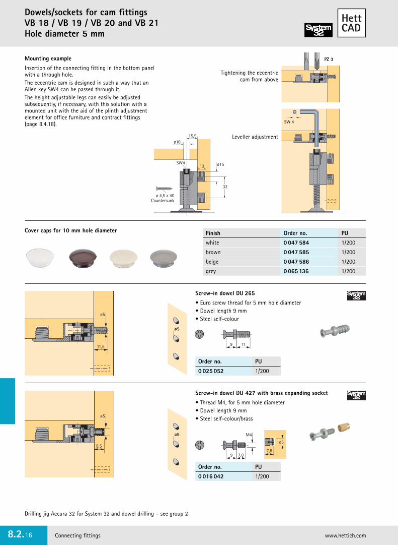
Dowels/sockets for cam fittingsVB 18 / VB 19 / VB 20 and VB 21Hole diameter 5 mm
Connecting fittings www.hettich.com8.2.16
SW 4
Leveller adjustment
Tightening the eccentriccam from above
Mounting example
Insertion of the connecting fitting in the bottom panelwith a through hole.The eccentric cam is designed in such a way that anAllen key SW4 can be passed through it.The height adjustable legs can easily be adjustedsubsequently, if necessary, with this solution with amounted unit with the aid of the plinth adjustmentelement for office furniture and contract fittings (page 8.4.18).
Cover caps for 10 mm hole diameter
PZ 3
11,5
ø5
ø5
8,5
Screw-in dowel DU 427 with brass expanding socket
• Thread M4, for 5 mm hole diameter• Dowel length 9 mm• Steel self-colour/brass
9 7,8
M4
9 11
ø5
7,8
ø5
ø5
Screw-in dowel DU 265
• Euro screw thread for 5 mm hole diameter• Dowel length 9 mm• Steel self-colour
Drilling jig Accura 32 for System 32 and dowel drilling – see group 2
Finish Order no. PU
white 0 047 584 1/200
brown 0 047 585 1/200
beige 0 047 586 1/200
grey 0 065 136 1/200
Order no. PU
0 025 052 1/200
Order no. PU
0 016 042 1/200
ø 4,5 x 40
32
ø1513SW4
15,5ø10
Countersunk

Connecting fittings 8.2.17
Dowels/sockets for cam fittingsVB 18 / VB 19 / VB 20 and VB 21
Hole diameter 5 mm
ø5
19
Knock-in double dowel DU 714
• For 19 mm centre panel• Hole diameter 5 mm• Dowel length 9 mm• Steel self-colour
ø5
9 19 9
ø5
Screw-in dowel DU 427 with threaded sleeve
• Thread M4• Hole diameter 5 mm• Dowel length 9 mm• Steel self-colour
9 7,8
M4
L
PU 200 = 200 dowels + 100 sleeves
ø5
Drilling jig Accura 32 for System 32 and dowel drilling – see group 2
Threaded sleeve Order no. PULength L mm
15 0 016 043 1/200
18 0 016 044 1/200
22 0 016 045 1/200
Order no. PU
0 079 639 1/100

Cam fitting VB 35
Connecting fittings www.hettich.com8.2.18
• Decorative connecting fittings for positive connections ofpanels and sides according to the tried and trusted eccentriclatching principle
• The fitting is pressed into a 20 mm dia. hole.The panel can be inserted from above or from the front.
• For bottom panels, the eccentric cam can be tightened also from above. For this purpose, a through hole in the shelf is required.
9,5
20
16 12,5
8
+0,5
12
9,5
20
19 14
9,5
+0,5
12
Drilling patternfor panels
Dowel centre fromunderside of panel
Drilling patternfor panels
Insert panel from above or the front
Dowel centre fromunderside of panel
Connecting fitting VB 35/16for 16 mm panels
Connecting fitting VB 35/19for 19 mm panels
Article Finish Order no. PU
VB 35 D/16Die-cast zinc nickel-plated 0 065 509 1/200
VB 35/16 white 0 065 511 1/200Plastic brown 0 065 512 1/200
black 0 079 642 1/200
Article Finish Order no. PU
VB 35 D/19Die-cast zinc nickel-plated 0 065 513 1/200
VB 35/19 white 0 065 515 1/200Plastic brown 0 065 516 1/200
black 0 079 641 1/200
Tungsten carbide drill bit for VB 35/35 M
• For upright and hand drills onlyHole diameter mm Order no. PU
20 0 046 077 1
12 0 044 756 1
Dowels / sockets - see pages 8.2.22 - 8.2.24

Connecting fittings 8.2.19
Cam fitting VB 35 M
Article Finish Order no. PU
VB 35 MD/16Die-cast zinc nickel-plated 0 065 501 1/200
VB 35 M/16 white 0 065 503 1/200Plastic brown 0 065 504 1/200
black 0 079 644 1/200
Article Finish Order no. PU
VB 35 MD/19Die-cast zinc nickel-plated 0 065 505 1/200
VB 35 M/19 white 0 065 507 1/200Plastic brown 0 065 508 1/200
black 0 079 643 1/200
Tungsten carbide drill bit for VB 35/35 M
• For upright and hand drills onlyHole diameter mm Order no. PU
20 0 046 077 1
12 0 044 756 1
Dowels / sockets - see pages 8.2.22 - 8.2.24
Fit shelf inposition fromabove. Mounting aidwhen hangingshelves.
9,5
20
16 12,5
8
+0,5
12
9,5
20
19 14
9,5
+0,5
12
Drilling patternfor panels
Dowel centre fromunderside of panel
Drilling patternfor panels
Dowel centre fromunderside of panel
Connecting fitting VB 35 M/16for 16 mm panels
Connecting fitting VB 35 M/19for 19 mm panels
• Decorative connecting fittings for positive connections ofpanels and sides according to the tried and trusted eccentriclatching principle
• The connecting fittings are equipped with a torque support which allows panels to be up to 2 mm apart before tightening.
• The fitting is pressed into a 20 mm dia. hole. The panel can be inserted from above.
• For bottom panels, the eccentric cam can be tightened also from above. For this purpose, a through hole in the shelf is required.

Cam fitting VB 36
Connecting fittings www.hettich.com8.2.20
Insert panel from above orthe front
• Decorative connecting fittings for positive connections ofpanels and sides according to the tried and trusted eccentriclatching principle
• The fitting is pressed into double holes with a drillingdistance of 32 mm. 20 mm and 10 mm diameter insertiondrilling holes. The panel shelf can be inserted from above or from the front.
• For bottom panels, the eccentric cam can be tightened also from above. For this purpose, a through hole in the shelf is required.
+0,5
8
10 20
32
9,5
1610,5 12,5
12 12
10
9,5
20
32
1910,5 14
9,5
+0,5Drilling patternfor panels
Drilling patternfor panels
Dowel centre fromunderside of panel
Dowel centre fromunderside of panel
Connecting fitting VB 36/16for 16 mm panels
Connecting fitting VB 36/19for 19 mm panels
Article Finish Order no. PU
VB 36 D/16Die-cast zinc nickel-plated 0 065 525 1/200
VB 36/16 white 0 065 527 1/200Plastic brown 0 065 528 1/200
black 0 079 645 1/200
Article Finish Order no. PU
VB 36 D/19Die-cast zinc nickel-plated 0 065 529 1/200
VB 36/19 white 0 065 531 1/200Plastic brown 0 065 532 1/200
black 0 079 646 1/200
Tungsten carbide drill bit for VB 36/36 M
• For upright and hand drills onlyHole diameter mm Order no. PU
20 0 046 077 1
10 0 046 079 1
12 0 044 756 1
Dowels / sockets - see pages 8.2.22 - 8.2.24

Connecting fittings 8.2.21
Cam fitting VB 36 M
+0,5
8
10 20
32
9,5
1610,5 12,5
12 12
10
9,5
20
32
1910,5 14
9,5
+0,5Drilling patternfor panels
Dowel centre fromunderside of panel
Drilling patternfor panels
Dowel centre fromunderside of panel
Tungsten carbide drill bit for VB 36/36 M
• For upright and hand drills onlyHole diameter mm Order no. PU
20 0 046 077 1
10 0 046 079 1
12 0 044 756 1
Fit shelf inposition fromabove.Mounting aidwhen hangingshelves.
• Decorative connecting fittings for positive connections ofpanels and sides according to the tried and trusted eccentriclatching principle
• The connecting fittings are equipped with a torque support which allows panels to be up to 2 mm apart before tightening
• The fitting is pressed into double holes with a drilling distanceof 32 mm. 20 mm and 10 mm diameter insertion drillingholes. The panel can be inserted from above.
• For bottom panels, the eccentric cam can be tightened also from above. For this purpose, a through hole in the shelf is required.
Connecting fitting VB 36 M/16for 16 mm panels
Connecting fitting VB 36 M/19for 19 mm panels
Article Finish Order no. PU
VB 36 MD/16Die-cast zinc nickel-plated 0 065 517 1/200
VB 36 M/16 white 0 065 519 1/200Plastic brown 0 065 520 1/200
black 0 079 647 1/200
Article Finish Order no. PU
VB 36 MD/19Die-cast zinc nickel-plated 0 065 521 1/200
VB 36 M/19 white 0 065 523 1/200Plastic brown 0 065 524 1/200
black 0 079 648 1/200
Dowels / sockets - see pages 8.2.22 - 8.2.24

Dowels for VB 35/35 M, VB 36/36 M, VB 135Hole diameter 3 and 5 mm
Connecting fittings www.hettich.com8.2.22
11,5
ø3
Screw-in dowel DU 261• Euro screw thread for 3 mm hole diameter• Dowel length 6,7 mm• Galvanized steel
13,5
ø5
Screw-in dowel DU 261
• Dowel length 6,7 mm• Galvanized steel
Expanding socket no. 43
• Hole diameter 5 mm• Plastic, self-colour
ø5
11,5
Screw-in dowel DU 279
• Only for VB 35/36• With high collar• Euro screw thread for 5 mm hole diameter• Dowel length 6,7 mm• Galvanized steel
ø5
8
Screw-in dowel DU 260
• Euro screw thread for 5 mm hole diameter• Dowel length 6,7 mm• Galvanized steel
ø5
ø5
ø5
ø3
136,7 11
6,7 11
3
6,7 11
6,7 7,8
Order no. PU
0 065 540 1/200
Order no. PU
0 074 688 1/200
Order no. PU
0 064 872 1/200
Article Order no. PU
Screw-in dowel DU 261 0 065 540 1/200
Expanding socket no. 43 0 048 577 1/200
Drilling jig Accura 32 for System 32 and dowel drilling – see group 2

Connecting fittings 8.2.23
Dowels/sockets for VB 35/35 M, VB 36/36 M, VB 135
Hole diameter 8 and 10 mm
Drilling jig Accura 32 for System 32 and dowel drilling – see group 2
12,5
ø8/10
Screw-in dowel DU 648
• Thread M6 x 7,8 mm• Dowel length 6,7 mm• Steel
ø8/10
6,7 7,8
M6
DU 648 can be used with...
ø8
11
ø10
11
13
12
13
ø10
12
11
ø8
9/12
ø8
ø10ø8 ø10
ø10 ø10
Expanding socket with/without nylon ball
• For thread M6• Hole diameter 8 mm• Brass self-colour
Socket no. 49
• For thread M6• Hole diameter 8 mm• White plastic
Socket no. 100
• For thread M6• Hole diameter 10 mm• White plastic
Socket strip no. 1
• For thread M6• Hole diameter 10 mm• 20 items per strip• White plastic
Length Order no. PU
9 mm without ball 0 079 537 1/200
12 mm with ball 0 079 538 1/200
Order no. PU
0 079 540 1/200
Order no. PU
0 040 005 1/200
Order no. PU
0 079 539 1/200
Order no. PU
0 079 541 1/200
Order no. PU
0 079 542 1/200
Socket no. 33
• For thread M6• Hole diameter 10 mm• White plastic
Socket strip no. 330
• For thread M6• Hole diameter 10 mm• 20 items per strip• White plastic
Finish Order no. PU
self-colour 0 065 534 1/200
chrome-plated 0 079 650 1/200
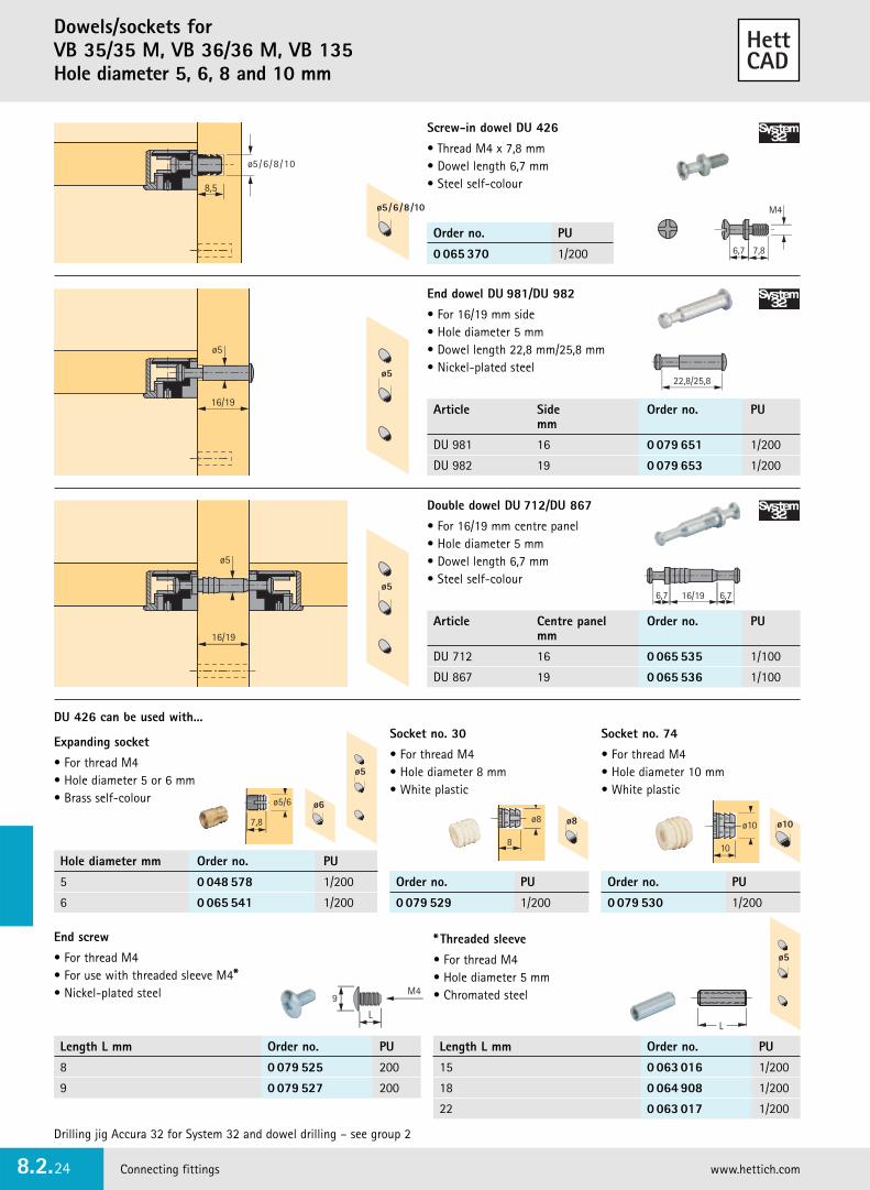
Dowels/sockets for VB 35/35 M, VB 36/36 M, VB 135Hole diameter 5, 6, 8 and 10 mm
Connecting fittings www.hettich.com8.2.24
6,7 7,8
M4
8,5
ø5/6/8/10
Screw-in dowel DU 426
• Thread M4 x 7,8 mm• Dowel length 6,7 mm• Steel self-colour
ø5/6/8/10
Order no. PU
0 065 370 1/200
ø5
16/19
End dowel DU 981/DU 982
• For 16/19 mm side• Hole diameter 5 mm• Dowel length 22,8 mm/25,8 mm• Nickel-plated steelø5
22,8/25,8
Article Side Order no. PUmm
DU 981 16 0 079 651 1/200
DU 982 19 0 079 653 1/200
Article Centre panel Order no. PUmm
DU 712 16 0 065 535 1/100
DU 867 19 0 065 536 1/100
ø5
16/19
Double dowel DU 712/DU 867
• For 16/19 mm centre panel• Hole diameter 5 mm• Dowel length 6,7 mm• Steel self-colour
ø56,7 16/19 6,7
DU 426 can be used with...
ø5/6
7,8 ø8
8
Socket no. 30
• For thread M4• Hole diameter 8 mm• White plastic
ø10
10
Socket no. 74
• For thread M4• Hole diameter 10 mm• White plastic
Expanding socket
• For thread M4• Hole diameter 5 or 6 mm• Brass self-colour
ø5
ø6
ø8 ø10
Hole diameter mm Order no. PU
5 0 048 578 1/200
6 0 065 541 1/200
Order no. PU
0 079 529 1/200
Order no. PU
0 079 530 1/200
ø5* Threaded sleeve
• For thread M4• Hole diameter 5 mm• Chromated steel
LL
9M4
Length L mm Order no. PU
8 0 079 525 200
9 0 079 527 200
Length L mm Order no. PU
15 0 063 016 1/200
18 0 064 908 1/200
22 0 063 017 1/200
End screw
• For thread M4• For use with threaded sleeve M4*• Nickel-plated steel
Drilling jig Accura 32 for System 32 and dowel drilling – see group 2

Connecting fittings 8.2.25
Cam fittingStabilofix
Order no. PU
0 030 900 1/100
Article Order no. PU
Rail with 2 stops
1000 mm 0 014 825 1
1500 mm 0 015 328 1
2000 mm 0 014 826 1
2500 mm 0 014 827 1
Drilling body for Stabilofix 0 040 009 1
Centre punch 0 023 680 1
• The connecting system for singled-handed assembly• Engage: Push-fit the furniture components together,
engagement of the metal claw is distinctly audible. The components are now loosely fixed together.
• Tighten: The eccentric cams are tightened only once the carcasehas been erected. In doing so, the screwdriver can beused at an angle.
• The fitting can be used for corner connections froma wood thickness of 16 mm upwards
• Front drilling holes or dowels are not required• Nickel-plated/die-cast zinc
Exacta universal drilling template
• Rational handling of the Stabilofix connecting fittings is easy using this tool
• The drilling jig is simple to use and always ensures exactpositioning of the fittings. see group 2
Drilling pattern for construction panel
• To release the fitting, the eccentric cam must be rotated anti-clockwise to the stop position
• After disassembly, all the eccentric cams should be rotated slightly clockwise in order to re-set the clip for subsequentreassembly
A
ø30
11ø30
12+0,3
12 +0,3 B
2,5
Rail
Hole pattern
Centre punch
Central marking
Centring holesCentringholes
Adjustable stop
Fixed stop
Pivot
Drilling jig
Hole distance A = B + 2,5 mm
Tungsten carbide tipped drill bit ø 30 mm for Stabilofix VB 62 D
• Shaft 10 mm, cylindrical• For upright and hand drills only
Order no. PU
0 046 072 1

Cam fitting VB 47
Connecting fittings www.hettich.com8.2.26
Order no. PU
0 079 655 1/100
• Cam fitting – without screws or projecting components, panels can be stacked flat
• User-friendly assembly via angled eccentric cam: the screwdriver can be used at an angle
• With screw-in dowel• Zinc/white plastic
Hole pattern
S
A
X
ø535
12 ø25
A = min. 15 mmX = 7 to 8 mm
Hole distance A =Side S - X + 6 mm
Mounting example
Tungsten carbide drill bit ø 25 mm for VB 47
• Shaft 10 mm, cylindrical• For upright and hand drills only
Order no. PU
0 046 074 1

Connecting fittings 8.2.27
Connecting fitting VB 25 T/ VB 35 T
Connecting fitting VB 25 T
• For sturdy, positive-fitting and friction-locked connectionswith high load-bearing capacity
• An 90° angle gear with hexagon socket integrated in theplastic housing permits fast, convenient bracing withcordless screwdriver
• Dowel length 50 - 60 mm• Minimum housing drilling depth 20 mm• Housing drill hole ø 25 mm• Through-hole ø 7 mm
Connecting fitting VB 35 T
• For sturdy, positive-fitting and friction-locked connectionswith high load-bearing capacity
• An 90° angle gear with hexagon socket integrated in theplastic housing permits fast, convenient bracing withcordless screwdriver
• Dowel length 64 mm• Minimum housing drilling depth 20 mm• Housing drill hole ø 35 mm• Through-hole ø 7 mm
Order no. PU
9 079 555 1/50
Order no. PU
9 079 557 1/50
64 21
ø10
ø7
20
ø35ø6ø35
= =
21
ø10
ø25
50-60
ø7
ø25
ø6
ø5
20
= =
Assembly Assembly
50-60
ø25ø7
ø10
ø25
64
ø35ø7
ø10
ø35
min. 21 min. 21
min. 20 min. 20
�
�
�
�
�
�
�
�

60
Mitre connector VB 45 - 90 T/ VB 90 - 180 T
Connecting fittings www.hettich.com8.2.28
Mitre connector VB 45 - 90 T
• For sturdy, positive-fitting and friction-locked connections withhigh load-bearing capacity
• Infinitely adjustable for angled connections of 45° - 90°• An 90° angle gear with hexagon socket integrated in the
plastic housing permits fast, convenient bracing with cordlessscrewdriver
• Dowel length 60 mm• Minimum housing drilling depth 20 mm• Housing drill hole ø 25 mm• Through-hole ø 7 mm
Mitre connector VB 90 - 180 T
• For sturdy, positive-fitting and friction-locked connections withhigh load-bearing capacity
• Infinitely adjustable for angled connections of 90° - 180°• An 90° angle gear with hexagon socket integrated in the
plastic housing permits fast, convenient bracing with cordlessscrewdriver
• Dowel length 60 mm• Minimum housing drilling depth 20 mm• Housing drill hole ø 25 mm• Through-hole ø 7 mm
Order no. PU
9 079 564 1/50
Order no. PU
9 079 561 1/50
60 60
ø25
ø7
ø25
ø6
ø5
20
= =
60 21
ø10
ø2525
ø7 ø6
ø5
20
= =
60 60
ø25
ø7
-45∞ 45∞
90∞
Assembly Assembly �
�
�
�
��
�
�
�

Connecting fittings 8.2.29
Block connecting fittingsTZ 4 / TZ 4 TD for solid wood furniture
Block connecting fitting TZ 4
• With premounted screw• TZ 4 all-metal:
Angled screw for particularly easy installation• Base section with spikes• Housing: die-cast zinc or plastic• Base section: steel
15
4 mm dia. chipboard/wood screw
TZ 4all metal
TZ 4plastic /steel
15
9
10,5
3340
15
22
20,5
15,8
3
40
15
22
20,5
15,8
Block connecting fitting TZ 4 TD
• With premounted screw• Simple installation via special clip mechanism• Upper and lower component made of metal• Distortion/shrinkage of solid wood is allowed
for by tolerance range of 4 mm• Housing: die-cast zinc• Base section: steel
9
12,2
30,540
15
22
20,5
15,8
15
6
4
Finish Order no. PU
nickel-plated 0 020 891 1/100
bronze 0 070 733 1/100
Article Finish Order no. PU
� TZ all metal nickel-plated 0 020 843 1/100
bronze 0 048 569 1/100
� TZ 4 plastic/ white 0 013 104 1/100steel brown 0 013 105 1/100
� �

Block connecting fittings TZ 321/TZ 28
Connecting fittings www.hettich.com8.2.30
16
ø10
ø510,5
6
13,5
Block connecting fitting TZ 321
• Press-in• Socket length 10 mm• Can be used in System 32• Panhead screw, steel, chromated• Housing and socket: white plastic
Order no. PU
0 016 031 1/100
9,5
ø8
10,5
Block connecting fitting TZ 28
• Press-in• Socket length 10 mm• Fixing with 4 mm dia. countersunk screw,
screwdriver can be used at an angle• White plastic
Order no. PU
0 072 053 1/100
Connecting fittings 8.2.31
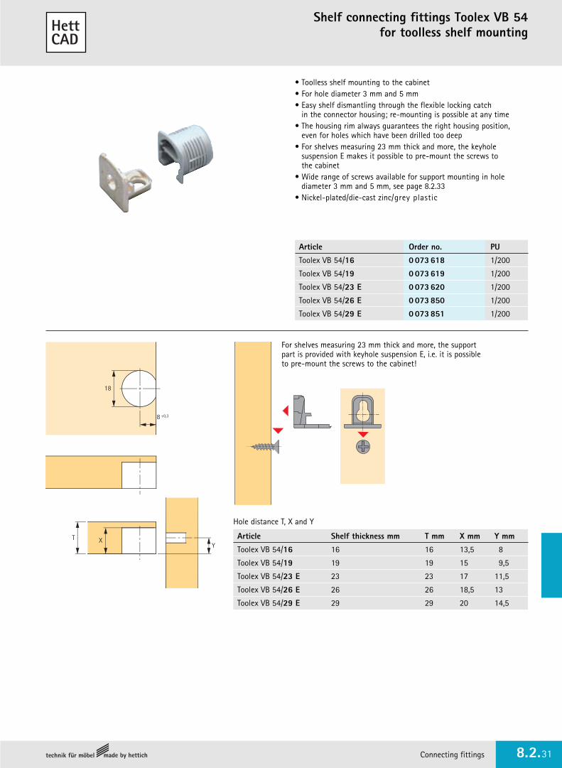
Shelf connecting fittings Toolex VB 54for toolless shelf mounting
• Toolless shelf mounting to the cabinet• For hole diameter 3 mm and 5 mm• Easy shelf dismantling through the flexible locking catch
in the connector housing; re-mounting is possible at any time• The housing rim always guarantees the right housing position,
even for holes which have been drilled too deep• For shelves measuring 23 mm thick and more, the keyhole
suspension E makes it possible to pre-mount the screws to the cabinet
• Wide range of screws available for support mounting in holediameter 3 mm and 5 mm, see page 8.2.33
• Nickel-plated/die-cast zinc/grey plastic
Article Order no. PU
Toolex VB 54/16 0 073 618 1/200
Toolex VB 54/19 0 073 619 1/200
Toolex VB 54/23 E 0 073 620 1/200
Toolex VB 54/26 E 0 073 850 1/200
Toolex VB 54/29 E 0 073 851 1/200
Article Shelf thickness mm T mm X mm Y mm
Toolex VB 54/16 16 16 13,5 8
Toolex VB 54/19 19 19 15 9,5
Toolex VB 54/23 E 23 23 17 11,5
Toolex VB 54/26 E 26 26 18,5 13
Toolex VB 54/29 E 29 29 20 14,5
Hole distance T, X and Y
8
Y
+0,3
18
T X
For shelves measuring 23 mm thick and more, the supportpart is provided with keyhole suspension E, i.e. it is possibleto pre-mount the screws to the cabinet!
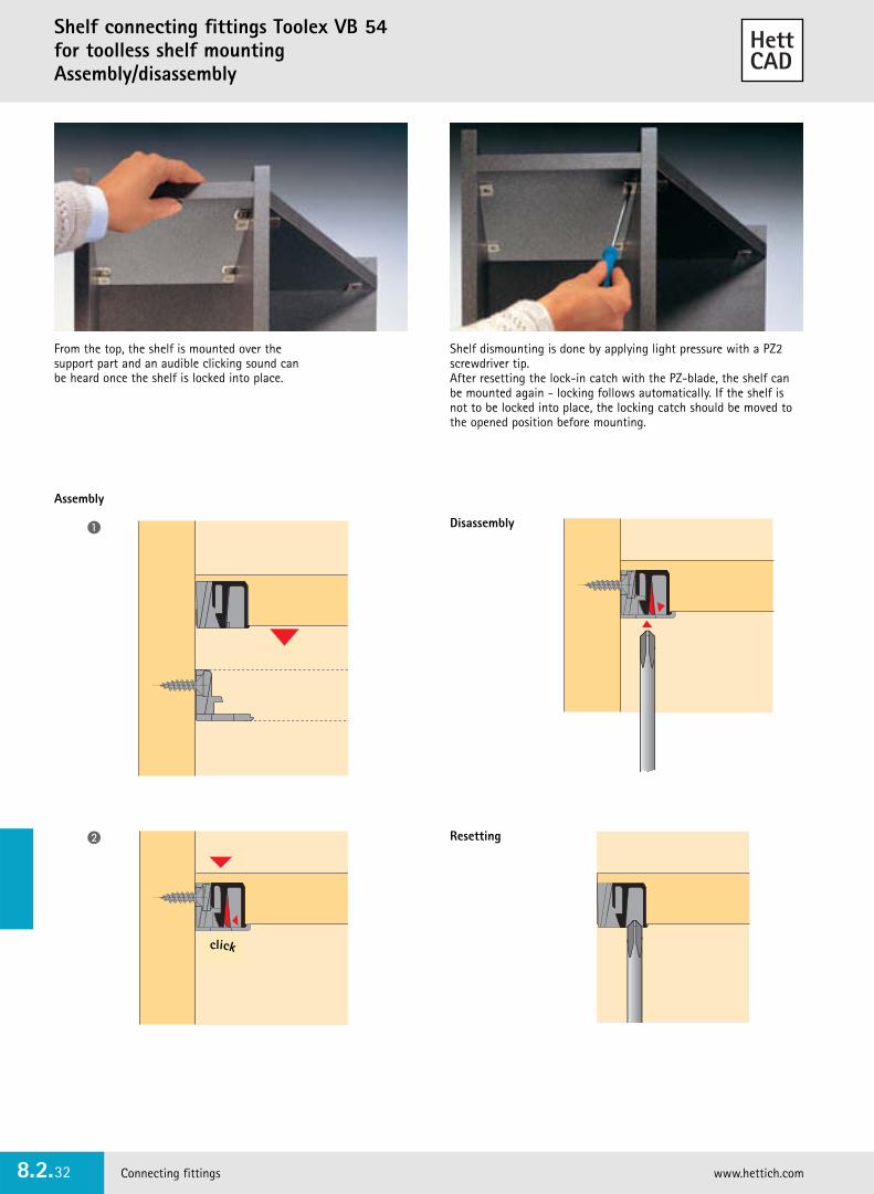
Shelf connecting fittings Toolex VB 54for toolless shelf mounting Assembly/disassembly
Connecting fittings www.hettich.com8.2.32
From the top, the shelf is mounted over thesupport part and an audible clicking sound canbe heard once the shelf is locked into place.
Shelf dismounting is done by applying light pressure with a PZ2screwdriver tip. After resetting the lock-in catch with the PZ-blade, the shelf canbe mounted again - locking follows automatically. If the shelf isnot to be locked into place, the locking catch should be moved tothe opened position before mounting.
klick
Assembly
Disassembly
Resetting
�
�
click

Connecting fittings 8.2.33
Shelf connecting fittings Toolex VB 54for toolless shelf mounting
Mounting applications
Range of application Screw dimensions For hole diameter Order no. PUmm mm
VB 54/16, 19, 23, 26, 29 6,3 x 15 5 0 073 889 200
VB 54/16 + 19 6,3 x 10,5 5 0 073 890 200
VB 54/16 + 19 6,3 x 12,5 5 0 073 752 200
VB 54/16, 19, 23, 26, 29 4,5 x 13,5 3 0 073 751 200
VB 54/16, 19, 23, 26, 29 5,0 x 16 3 0 073 891* 200
Euro screw
*Special screen for softwood
Drill for Blue Max/Blue Max Mini
Mounting applications with Euro screws
19
12
ø5 ø5
19
7,5
ø5
9,5
19
ø3
11,5
19
19
14
ø3
Order no.: 0 073 889
Order no.: 0 073 891
Order no.: 0 073 890 Order no.: 0 073 752 Order no.: 0 073 751
Use for soft wood
Tungsten carbide drill bit ø 18 mm for VB 54
• Shaft 10 mm, cylindrical• For upright and hand drills only
Order no. PU
0 046 087 1
Article Order no. PU
Drill, diameter 18 mm left 0 073 143 1
Drill, diameter 18 mm right 0 073 099 1

!
Connecting fittings www.hettich.com8.2.34
Fit shelf in positionfrom above.Mounting aid whenhanging shelves.
8
16 12,5
+0,5
20
9,5Drilling patternfor panels
Dowel centrefrom underside of panel
Shelf connecting fittings VB 135AVB HT Worktop connector for lightweight worktops
• The connecting fitting VB 135 is pressed into a 20 mm dia. Hole• The panel can only be inserted from above• The panel with the VB 135 is merely pressed on to the dowel.
Via the wedge effect, the shelf is tightened on the side andsafeguarded against accidental removal.
• Can be used with panels from 16 mm upwards• Plastic
Dowels/sockets - see pages 8.2.22 - 8.2.24
Finish Order no. PU
white 0 073 616 1/200
brown 0 073 617 1/200
black 0 079 649 1/200
Order no. PU
0 046 077 1
Worktop connector AVB HT
• For sturdy, positive-fitting and friction-locked connections between lightweight worktops
• For Worksop thicknesses of 50 and 60 mm• Suitable for use with 8 mm surface layers• Housing drill hole ø 40 mm• Drilling depth 46 or 56 mm• An 90° angle gear with hexagon socket integrated in the plastic
housing permits fast, convenient bracing with cordless screwdriver• Chromated steel/black plastic
�
Assembly
Length Dimension X Worktop thickness VEmm mm 50 mm 60 mm
65 33 - 44 9 079 567 9 080 216 1/20
100 49 - 61 9 079 570 9 080 217 1/20
150 75 - 86 9 079 571 9 080 218 1/20
8
8
4
8
50 / 60
ø40
13
X X
Tungsten carbide drill bit ø 20 mm for VB 135
• Shaft 10 mm, cylindrical• For upright and hand drills only
�
13
Connecting fittings 8.2.35
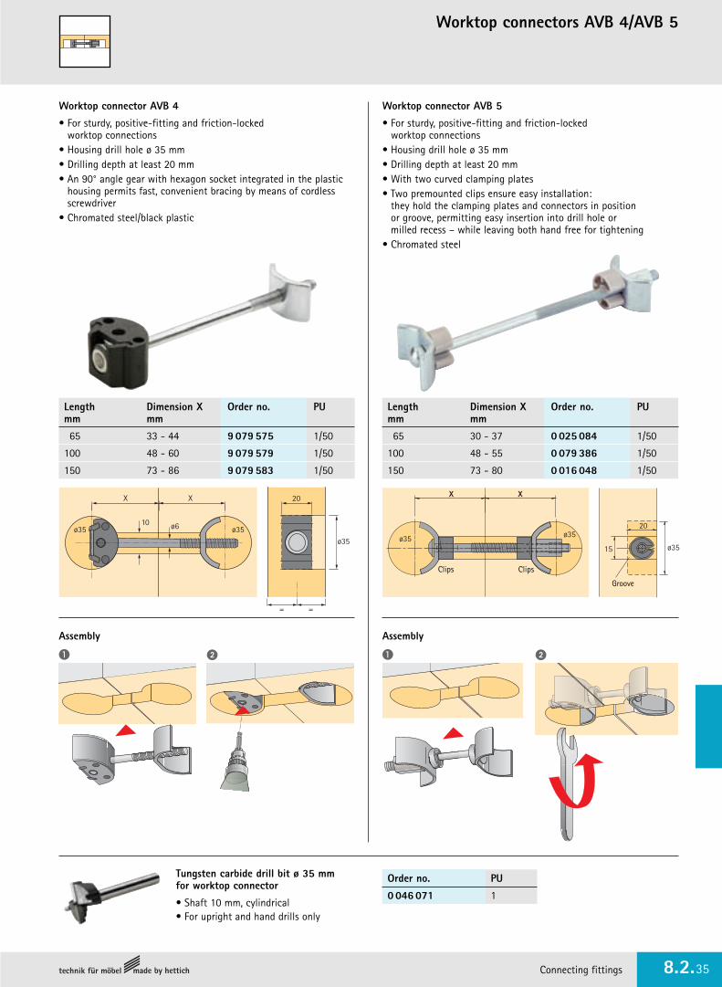
Worktop connectors AVB 4/AVB 5
Worktop connector AVB 4
• For sturdy, positive-fitting and friction-locked worktop connections
• Housing drill hole ø 35 mm• Drilling depth at least 20 mm• An 90° angle gear with hexagon socket integrated in the plastic
housing permits fast, convenient bracing by means of cordlessscrewdriver
• Chromated steel/black plastic
Worktop connector AVB 5
• For sturdy, positive-fitting and friction-locked worktop connections
• Housing drill hole ø 35 mm• Drilling depth at least 20 mm• With two curved clamping plates• Two premounted clips ensure easy installation:
they hold the clamping plates and connectors in position or groove, permitting easy insertion into drill hole or milled recess – while leaving both hand free for tightening
• Chromated steel
Assembly
Length Dimension X Order no. PUmm mm
65 30 - 37 0 025 084 1/50
100 48 - 55 0 079 386 1/50
150 73 - 80 0 016 048 1/50
Length Dimension X Order no. PUmm mm
65 33 - 44 9 079 575 1/50
100 48 - 60 9 079 579 1/50
150 73 - 86 9 079 583 1/50
� �
Assembly
� �
Tungsten carbide drill bit ø 35 mm for worktop connector
• Shaft 10 mm, cylindrical• For upright and hand drills only
Order no. PU
0 046 071 1
X X
ø35ø35 ø6
20
ø35
= =
10 20
15
XX
ø35 ø35
ø35
Clips Clips
Groove

Non-release connecting fitting Everfix
Connecting fittings www.hettich.com8.2.36
• This inconspicuous connecting fitting consists merely of a threaded stud anda knock-in socket with a spring steel disc
• Components can therefore be push-fitted easily and permanently by hand• Pull-out strength 800 N
Connecting fittingEverfix with Duplo
Drill for socket Position hole marking templateand mark hole centre for studwith the centre point
Drill for stud Position hole marking templateand mark hole centre for socketwith the centre point
Hole marking template for Everfix
Connecting fittingEverfix with threaded studfor 5 mm drilling
PU 200 = 400 Everfix + 200 Duplo
Order no. PU
0 079 118 1/200
Order no. PU
0 079 692 1
Order no. PU
0 079 119 1/200
Tungsten carbide drill bit for connecting fitting Everfix
• For upright and hand drills only
Hole diameter mm Order no. PU
12 0 044 756 1
5 0 046 083 1
9,5
ø5
ø12
9,5
ø12min. 13
min. 13
min. 3
min. 16,5
min. 13

Connecting fittings 8.2.37
Non-release connecting fitting Everfix
Drawer connectionCarcase construction
Surface connection
Stair construction
Column connection
Rail connection
Fascia connection
• Can be used as drawer-front connector, drawerconnector, for decorative ceiling panelling, in shelf and stair construction
• Excellently suited also for flat pack or smallfurniture. Simply press together!
• Everfix provides economic advantages in allcases in which wooden components are traditionally connected using wooden dowels
• Immediate hold, non-release and invisible• High rigidity, with 80 kg pull-out strength• Toolless installation• No waiting time for glue to set• Large tolerance compensation• No need for carcase clamps

Clip connector MultiClip
Connecting fittings www.hettich.com8.2.38
A single plastic component, simple and easy to use!MultiClip is rectangular in shape and can be screwed in place from all sides. Fits easily into system 32 drilling.Multi-Clip locates by means of a flexible tongue. These tongues areserrated and slightly sprung in order to provide a firm location. Multi-Clip’s wide tolerance band provides significant adjustment after location.
6
6
32
32
32
44
64
15
Mounting with 4 mm dia. countersunkscrews
MultiClip is versatile in use:
• For wall panelling, plinths, fascia panels and cladding of all types• In all cases, the fitting can be screwed on parallel or at a right
angle to the fascia or cladding component• If the clip connectors have to be pushed on from the front,
one of the fittings is screwed on at an angle of 90°• The drawings opposite show just some of the applications possible
with Multi-Clip. Simple, easy and economical• Only 1 fitting for all types of application• Strong location via spring-loaded flexible tongues
with serrated surfaces• Variable screw-on positions allow fixing from above,
from the front, from the side etc.• Compensation of installation tolerances• Adjustability after installation• Made from heat-resistant thermoplastic
Order no. PU
0 046 080 1/200

Connecting fittings 8.2.39
Connecting fitting VB 90for 30 - 270 degrees angle connections
Order no. PU
0 030 891 1/100
Order no. PU
0 079 540 1/200
• Unit elements or drawer front components with extreme anglescan be connected without difficulty using this fitting
• E.g.: angled fascia panels in office furniture• The joint is adaptable to all angles of between 30 and 270 degrees• Nickel-plated/die-cast zinc
Fixing with euro screws in a hole diameter of 5 mm or hexagon head screw M6 and socket no. 100 for 10 mm hole diameter
The VB 90 convinces by its user-friendly assembly:Fix the fitting to the first side initially and slide on to a pre-fixed screw on the second component.For angles of less than 90°, a hexagon head screw should be used toallow final fixing with a spanner.
6,5 24
1616
128
4 thick
Socket no. 100
• White plastic
Connecting fitting VB 16 for cornicesMitre connector VB 160
Connecting fittings www.hettich.com8.2.40
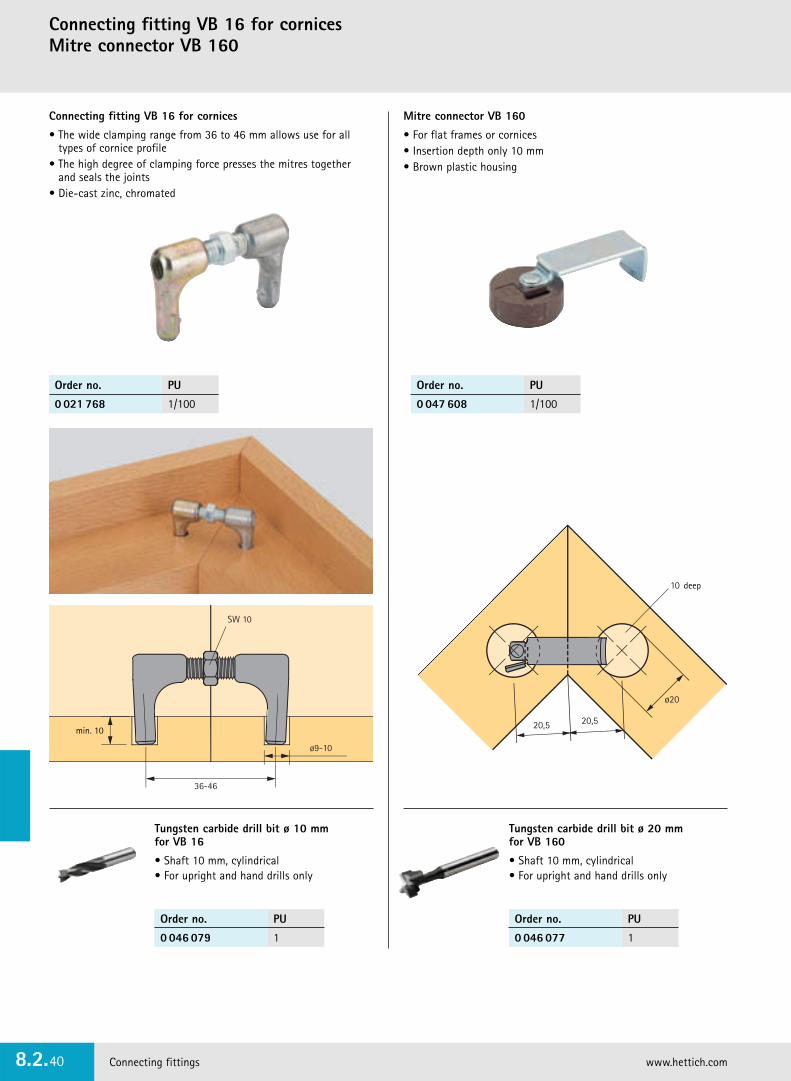
Connecting fitting VB 16 for cornices
• The wide clamping range from 36 to 46 mm allows use for alltypes of cornice profile
• The high degree of clamping force presses the mitres together and seals the joints
• Die-cast zinc, chromated
SW 10
ø9-10
36-46
Order no. PU
0 021 768 1/100
Order no. PU
0 047 608 1/100
Mitre connector VB 160
• For flat frames or cornices• Insertion depth only 10 mm• Brown plastic housing
20,5
ø20
20,5
10 deep
Tungsten carbide drill bit ø 10 mm for VB 16
• Shaft 10 mm, cylindrical • For upright and hand drills only
Order no. PU
0 046 079 1
Tungsten carbide drill bit ø 20 mm for VB 160
• Shaft 10 mm, cylindrical • For upright and hand drills only
Order no. PU
0 046 077 1
min. 10
Connecting fittings 8.2.41
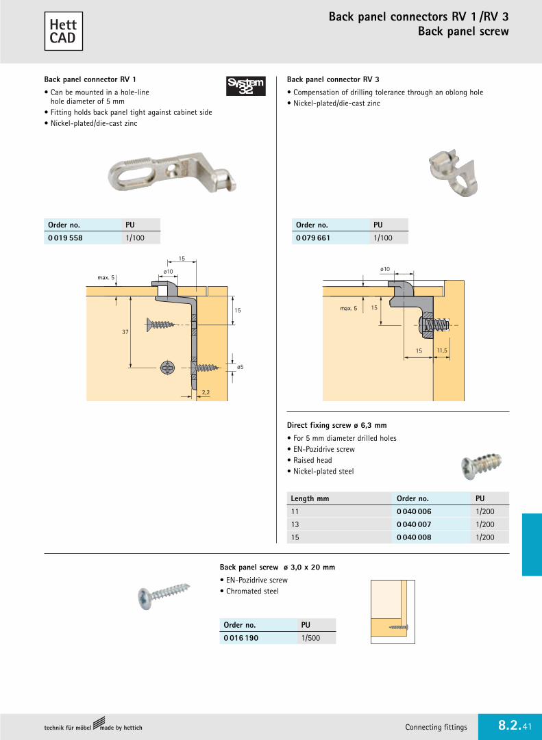
Back panel connectors RV 1 /RV 3Back panel screw
Order no. PU
0 019 558 1/100
Order no. PU
0 079 661 1/100
Order no. PU
0 016 190 1/500
Back panel connector RV 1
• Can be mounted in a hole-line hole diameter of 5 mm
• Fitting holds back panel tight against cabinet side• Nickel-plated/die-cast zinc
Back panel connector RV 3
• Compensation of drilling tolerance through an oblong hole• Nickel-plated/die-cast zinc
37
15
ø10
ø5
15
2,2
15
15
ø10
11,5
Back panel screw ø 3,0 x 20 mm
• EN-Pozidrive screw• Chromated steel
Direct fixing screw ø 6,3 mm
• For 5 mm diameter drilled holes• EN-Pozidrive screw• Raised head• Nickel-plated steel
Length mm Order no. PU
11 0 040 006 1/200
13 0 040 007 1/200
15 0 040 008 1/200
max. 5
max. 5

Back panel connectors RV 7 D/RV 8
Connecting fittings www.hettich.com8.2.42
• With the RV 7 D, the back panel is mounted from the inside
• This makes the assembly work easier, since it is possible to mount the cabinet against the wall
• The RV 7 D can be mounted with different types of fixing parts: with countersunk screw, with raised head screws M6 x 12 (DIN 7985) and screw cap or socket, with Euro screw or with the MultiClip
• Height is adjustable through oblong hole ±1mm
32
ø16
37ø519
15
32
16
37
32
ø1615
37ø5
ø10
32
ø16
37ø5
32
ø16
37ø515
� Rebated back panel, mountingwith Panhead screw diameter 4 x 12 mm
� Centre panel mountingwith Panhead screw diameter 4 x 12 mm
� Flush overlay back panel,mounting with MultiClip
� Flush overlay back panel(min. 16 mm), mountingwith raised head screw M6 x 12 (DIN 7985) withscrew cap M6
Examples of application RV 7D
� Flush overlay back panel(min. 16 mm), mounting withraised head screw M6 x 12(DIN 7985) and socket No. 1
Back panel connector RV 8
• For fixing drawer bottoms and rear panels
• White plastic
15
4,7
10,7
Artikel Material/ Order no. PUFinish
Back panel connectors die-cast zincRV 7 D nickel-plated 0 056 614 1/100
Euro screw steel6,3 x 13 nickel-plated 0 040 007 1/200
Countersunk screw steelø 3,5 x 12 chrome-plated 0 058 244 200
Countersunk screw steelø 4 x 12 Panhead chrome-plated 0 058 243 200
Pan head screw steelM6 x 12 (DIN 7985) nickel-plated 0 058 242 1/200
Screw cap M6 plasticwith slot white 0 058 301 1/200
Socket no. 100 plasticwhite 0 079 540 1/200
MultiClip plasticblack 0 046 080 1/200
Order no. PU
0 079 438 1

Connecting fittings 8.2.43
Front panel connector
16
ø5,5
7,5 17,5 30 17,5
80
2
Connecting plate for front panels
• Length: 80 or 200 mm• Blue passivated steel
2,5
20
ø4,5
200
80 474713
Front panel connector VB 15
• Includes plastic spacer, 2 mm thick
• Chromated steel
4
2
70
Order no. PU
0 079 666 1/100
Length mm Order no. PU
80 0 079 664 1/50
200 0 044 744 1/50

Connecting angle
Connecting fittings www.hettich.com8.2.44
Connecting angle for 32 mm hole lines
• Can be used universally as a connecting fitting for carcase panels, back panels and drawer fronts
• Chromated steel
Cover cap
• Plastic
2
7
2515
11,5
ø7
20,7 16
4232
5043,5
37
1637
Direct fixing screw ø 6,3 mm
• For 5 mm diameter drilled holes• EN-Pozidrive screw• With raised head• Nickel-plated steel
Article Finish Order no. PU
Connecting angle chrome-plated 0 024 832 1/200
Cover cap white 0 050 314 1/200
brown 0 050 313 1/200
RAL 7035 0 070 292 1/200
black 0 072 026 1/200
Length mm Order no. PU
11 0 040 006 1/200
13 0 040 007 1/200
15 0 040 008 1/200
One PU contains 100 connectors and 100 cover caps
ø3,5
10
10 ø5
25
25
20,520,5
43
9
9
Universal corner connector
• Universal corner connector for small carcases and light loading• Mounting with 3,5 mm dia. countersunk screws• The cover cap simply clips on to conceal the screws• Plastic
Finish Order no. PU
white 0 044 742 1/100
black 0 044 743 1/100

Connecting fittings 8.2.45
Connecting angle Keyhole fittings
14,5
20 6,3 32 42
2
ø4,85
6,5226244
12
18
2
ø4,8
Keyhole fitting 42 mm
• Blue passivated steel
Keyhole fitting 62 mm
• Blue passivated steel
Universal angle 41,5 x 41,5 mm
• Blue passivated steel
Universal angle 31 x 31 mm
• Blue passivated steel
25
1325
6,5 12
31 ø4,5
1325
31
ø4,5
2
17,5
16,5
16
ø5,5
41,5
41,5
Order no. PU
0 025 193 1/100
Order no. PU
0 025 194 1/100
Order no. PU
0 025 197 1/100
Order no. PU
0 079 665 1/100

One-piece connector Direkta 2Connecting screws
Connecting fittings www.hettich.com8.2.46
ø7
ø5
� One-piece connector Direkta 2
• With drilled head and Pozidrive screw• Chromated steel
� Cover cap for Direkta 2
• Plastic
� Stepped drill HSS 5 mm dia. / 7 mm dia.
� Depth adjustment ring
�
�
�
�
Connecting screws VHS 32
• Carcase connector for extra strength• For 5 mm dia. drilling• The connecting sleeves are 27 or 35 mm long.
The threaded sleeve is set back to facilitate screwing inof the connector screw.
• Screw M4 x 15 mm, nickel-plated steelConnecting sleeve, nickel-plated steel
ø5
Wood thickness
Article Wood thickness Order no. PUmm
VHS 32/27 28 - 36 0 079 659 1/100
VHS 32/35 36 - 44 0 079 660 1/100
Connecting screws VS
• Thread M6 for 8 mm hole diameter• Steel self-colour• Plastic head white or brown
ø8
PU 100 = 100 screws M6 + 100 caps
Wood thickness
Article Finish Wood thickness Order no. PUmm
VS 26 white 26 - 31 0 008 954 1/100
VS 29 white 29 - 36 0 013 108 1/100
VS 34 white 34 - 41 0 013 110 1/100
VS 39 white 39 - 46 0 013 112 1/100
VS 44 white 44 - 51 0 013 114 1/100
VS 49 white 49 - 56 0 008 956 1/100
VS 29 brown 29 - 36 0 013 109 1/100
VS 34 brown 34 - 41 0 013 111 1/100
VS 39 brown 39 - 46 0 013 113 1/100
VS 44 brown 44 - 51 0 013 115 1/100
Artikel Length mm/ Order no. PUFinish
� Direkta 2 6,3 x 40 0 019 555 1/500
6,3 x 50 0 019 556 1/500
� Cover cap white 0 016 339 1/500
for Direkta 2 brown 0 016 340 1/500
� Stepped drill 0 019 446 1
� Depth adjustment ring 0 024 838 1

Connecting fittings 8.2.47
Chipboard screwsExpanding sockets
Euro screws countersunk
Chipboard screw
• Countersunk• EN-Pozidrive screw• Nickel-plated steel
Chipboard screw• Panhead• EN-Pozidrive screw• Chromated steel
Expanding socket no. 66/no. 43
• For hole diameter 5 mm• Plastic, self-colour
Euro screw countersunk
• Countersunk• EN-Pozidrive screw• Steel
ø5
2,5Length
Expanding socket no. 42/no. 41
• With collar• For hole diameter 5 mm• Plastic, self-colour
Diameter Length Order no. PUmm mm
3,5 12 9 079 791 200
3,5 13 0 048 296 200
3,5 16 0 071 925 200
3,5 20 0 071 924 200
4,0 16 0 010 085 200
Diameter Length For hole diameter Finish Order no. PUmm mm mm
4,5 13,5 3 chrome-plated 0 073 751 200
6,3 11,0 5 nickel-plated 0 047 451 200
6,3 14,0 5 nickel-plated 0 047 452 200
6,3 18,0 5 nickel-plated 0 052 799 200
Diameter Length Order no. PUmm mm
3,5 12 0 045 167 200
3,5 20 0 045 168 200
4,0 12 0 058 243 200
Length mm Order no. PU
9,5 0 048 574 1/200
13,0 0 048 575 1/200
Length mm Order no. PU
9 0 048 576 1/200
13 0 048 577 1/200
Euro screw countersunk ø 6,3 mm
• Oval head• EN-Pozidrive screw• For hole diameter 5 mm• Nickel-plated steel
Length mm Order no. PU
11 0 040 006 1/200
13 0 040 007 1/200
15 0 040 008 1/200
ø5 ø5

Threaded screws M4Sockets with M4 thread
Connecting fittings www.hettich.com8.2.48
Length mm Order no. PU
12 0 071 544 50
14 0 071 545 50
16 0 071 546 50
18 0 071 547 50
20 0 071 548 50
22 0 071 549 50
24 0 071 555 50
26 0 071 556 50
28 0 071 557 50
30 0 071 558 50
32 0 071 559 50
34 0 071 560 50
36 0 071 561 50
38 0 071 562 50
40 0 071 563 50
42 0 071 855 50
45 0 071 856 50
Handle fixing screws
• Thread M4• Cross recessed head and double slot• Nickel-plated steel
Length mm Order no. PU
8 0 079 525 200
9 0 079 527 200
Length mm Order no. PU
15 0 063 016 1/200
18 0 064 908 1/200
22 0 063 017 1/200
End screw
• Thread M4• EN-Pozidrive screw• Nickel-plated steel
ø5
Threaded sleeve
• With thread M4• For hole diameter 5 mm• Chromated steel
L
Spreizmuffe
• With thread M4• For 5 or 6 mm hole diameter• Length 7,8 mm• Brass self-colour
ø5/6
7,8
ø5
ø6
ø8
8
Socket no. 30
• With thread M4• For hole diameter 8 mm• Length 8 mm• White plastic
ø8
Order no. PU
0 079 529 1/200
Socket no. 74
• With thread M4• For hole diameter 10 mm• Length 10 mm• White plastic
Order no. PU
0 079 530 1/200
ø10
10
ø10
Hole diameter mm Order no. PU
5 0 048 578 1/200
6 0 065 541 1/200

Connecting fittings 8.2.49
Screw with M5 threadSockets/threaded caps
Cone-shaped plugs
Length mm Order no. PU
9 (without nylon ball) 0 079 537 1/200
12 (with nylon ball) 0 079 538 1/200
Hole diameter mm Order no. PU
8 0 045 165 1/200
10 0 045 166 1/200
Sockets
• With thread M5• For 8 or 10 mm hole diameter• Length 11 mm• White plastic
Finish Order no. PU
white 0 058 301 1/200
brown 0 067 200 1/200
Screw cap
• With thread M6• For hole diameter 8 mm• Length 15 mm• Plastic
Sockets
• With thread M6• For 8 or 10 mm hole diameter• White plastic
Countersunk screw M5 x 11 mm
• EN-Pozidrive screw• Nickel-plated steel
Order no. PU
0 045 164 1/200
Expanding socket with/without nylon ball
• With thread M6• For hole diameter 8 mm• Brass self-colour
Finish Order no. PU
white 0 048 586 1/1000
brown 0 048 587 1/1000
Cone-shaped plug
• For hole diameter 5 mm• Plastic
Finish Order no. PU
white 0 048 590 1/1000
brown 0 048 591 1/1000
Cone-shaped plug
• For hole diameter 10 mm• Plastic
Finish Order no. PU
white 0 048 588 1/1000
brown 0 048 589 1/1000
beige 0 062 204 1/1000
Cone-shaped plug
• For hole diameter 8 mm• Plastic
ø8
9/12
ø8
ø13
5,5
6,5
ø13
6,5
ø13
Hole diameter Length Order no. PUmm mm
8 11 0 040 005 1/200
10 11 0 079 539 1/200
10 13 0 079 540 1/200
11
ø8 ø10Hole diameter
ø10ø8
Length
Hole diameter

Special screws
Connecting fittings www.hettich.com8.2.50
Length mm Order no. PU
14 0 046 700 1/200
16 0 046 701 1/200
Special screw ø 6,3 mm
• For fixing front panel• For 5 mm hole• EN-Pozidrive screw• Chromated steel
Length mm Order no. PU
14 0 076 222 1/200
16 0 052 996 1/200
28 0 052 995 1/200
Special screw ø 5 mm
• For fixing front panel• EN-Pozidrive screw• Chromated steel
Special screw ø 3,5 x 9,5 mm
• DIN 7982• For fitting hinge cups
in aluminium framed doors• EN-Pozidrive screw• Nickel-plated steel
Order no. PU
0 041 296 200
Special sheet metal screw ø 3,9 x 9,5 mm
• DIN 7982• E.g. for aluminium frame doors• Phillips screw• Countersunk
Order no. PU
0 041 331 200
Special sheet metal screw ø 4,8 x 13 mm
• DIN 7982• E.g. for aluminium frame doors• Phillips screw• Countersunk
Order no. PU
0 041 329 200
Order no. PU
0 065 480 1/100
Special screw and socket
• For T43 hinge cups• Buttress thread screw • EN-Pozidrive screw• Nickel-plated steel
Socket with collar
• For hole diameter 10 mm• Length 11 mm• White plastic
Order no. PU
0 045 169 200
Suspension hook ø 6 x 50 mm
• Steel self-colour
Dowel ø 8 x 40 mm
• Plastic, self-colour• Hook driver for cordless screwdriver
with hexagon receiversee page 2.4.4
Order no. PU
0 046 103 1/100
Special screw ø 3 x 20 mm
• For fixing the rear wall• EN-Pozidrive screw• Chromated steel
Order no. PU
0 016 190 1/500
Special screw ø 5,5 x 50 mm
• E.g. for rail mounting• EN-Pozidrive screw• Chromated steel
Dowel ø 8 x 40 mm
• Plastic, self-colour

Fittings for beds and upholstered furniture 8.3.1
Range summary8.3 Fittings for beds and upholstered furniturei
Connecting fittings for beds/bed fittings
8.3.2 - 8.3.4
Adjustable fittings for head and foot ends/spring-loaded bed fitting/under-bed storage wheels
8.3.5 - 8.3.6
Neck and arm rest adjuster for upholstered furnitureFrankoflex
8.3.7
Lid fitting for chests and corner benchesSchwenkfix
8.3.8
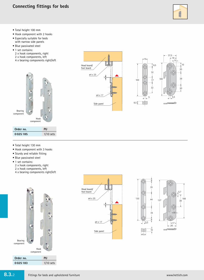
Fittings for beds and upholstered furniture www.hettich.com8.3.2
Connecting fittings for beds
• Total height 100 mm• Hook component with 2 hooks• Especially suitable for beds
with narrow side panels • Blue passivated steel• 1 set contains:
2 x hook components, right 2 x hook components, left 4 x bearing components right/left
• Total height 130 mm• Hook component with 3 hooks• Sturdy and reliable fitting• Blue passivated steel• 1 set contains:
2 x hook components, right 2 x hook components, left 4 x bearing components right/left
10
20
39
20
5,5
100
9
37,519
100
32
17
32
5
15
8,5
9,5
ø4 x 17
ø4 x 251
5,3
10
8
35
44130
35
26
5,7
38108
127
8
15
8
17ø4 x 17
ø4 x 25
1
Head board/foot board
Side panel
Head board/foot board
Side panel
Bearingcomponent
Hookcomponent
Bearing component
Hookcomponent
Order no. PU
0 025 185 1/10 sets
Order no. PU
0 025 183 1/10 sets

Fittings for beds and upholstered furniture 8.3.3
Connecting fittings for beds
• Total height 127 mm• Offset screw holes,
in grid spacing of 32 mm• Complete with sockets M6 x 13
and screws M6 x 12• Chromated steel
• Total height 226 mm• Screw holes in grid spacing of 32 mm• Especially suitable for beds with
high side panels• Complete with sockets M6 x 13
and screws M6 x 12• Chromated steel
96
17
96
16 22
6,213,5
226
64
64
32
17
32
4,5
3122
12
20
96
16 22
6,2
13,5
21,5
127
32
32
5,5
30
32
11,5
18,5
166,2
11
ø10
13,5
ø10
13,5
Stabilofix
• For dismountable upholstered beds or outer bed frames
• High level of tightening strength and up to 4 mm tolerance compensation
• Chromated steel
5,3
52
24
4525
52
12,5
17
10
34
90
32
32
43,5
22
13
18,5
45
Head board/foot board
Side panel
Order no. PU
0 025 189 1/40
Order no. PU
0 047 635 1/40
Order no. PU
0 047 634 1/40

Varifix – bed fitting with height adjustment featureSupporting leg for centre stay Centre rail connector
Fittings for beds and upholstered furniture www.hettich.com8.3.4
Varifix – bed fitting with height adjustment feature
• Single and double beds• The height of the support brackets can
be adjusted in 3 levels; each level allows a height adjustment of 24 mm
• Also suitable for double beds with centre support rail
• Blue passivated steel
Supporting leg for centre stay
• Ideal for use in combination with the bedfitting Varifix
• Black plastic
ø35
x+-
25
70
35
64
139,5
36 4,2
8
12*
48
35
Centre rail Hole size
* Offset for centre railmeasuring 35 mm thick
Support for bed frameSupport for centre rail
Varifix
Supporting leg
Centre rail connector
• For wooden or metal bed systems• Can also be used for sprung beds• Centre rail width up to 70 mm• Chromated steel
38,5
69
24
52
ø6,5
24 3118,5
38,5
67,5
21 21
ø5
8Centre rail
max. 70 mm wide
Head board/foot board
Order no. PU
0 047 633 1/40
Order no. PU
0 025 182 1/40
Tungsten carbide drill bit ø 35 mm for supporting leg
• Shaft 10 mm, cylindrical • For upright and hand drills only
Bestell-Nr. VE
0 046 071 1
Size X Adjustment Order no. PUmm mm
120 0/+106 0 073 480 1/20
150 -22/+ 96 0 047 630 1/20
170 -22/+ 96 0 047 631 1/20
190 -42/+ 76 0 047 632 1/20

Fittings for beds and upholstered furniture 8.3.5
Adjustable fittings for head and foot ends
Order no. PU
0 025 173 1/4
X9,5
11
ø8,2
30
214 - 219 mm for 10 notches141 - 146 mm for 5 notches
ø6
12
Outer frame for M6 screw
Spacer disc Inner frame
Multiflex
• Adjustable fitting for head and foot ends• 13 adjustment capabilities• Extremely compact design• Easy, fast assembly• Blue passivated steel
18
185
195
31
195
X
Size X mm5 notches 10 notches
1 R 164 234,5
5 R 214,5 28810 R 354
Number of notches Order no. PU
10 0 025 174 1/10
5 0 025 175 1/10
Rastomat
• Adjustable fitting for head and foot ends• Also suitable for height-adjustable desktops,
deck chairs and all types of flaps• The fitting engages in any notch without
having to return to the home position• Rugged construction• Safety feature prevents over-extension• The requisite spacer discs are enclosed
with the packaging units• Blue passivated steel
Position 0 1 2 3 4 5 6 7 8 9 10 11 12 13 Stop mm(max. opening)
Distance X mm 5 29 69 99 124 143 160 176 193 207 223 240 257 278 332
min. 45

Spring-loaded fittingBed frame wheel
Fittings for beds and upholstered furniture www.hettich.com8.3.6
Spring-loaded fitting for single beds, bunk beds and sprung beds
• All riveted connections with washers for stability• The spring force assists the swing action• Weight of bed frame including mattress 25 kg• Built-in designs should be constructed so that
the weight rests on the understructure on all four sides• A plastic fitting cover protects the bed linen
in the outer bed frame• Is only available as a set
comprising one left and one right fitting• Chromated steel
Bed frame wheel
• Large-sized wheel diameter with wide tread
• Easy to mount with connecting screws VS, see page 8.2.46
• White plastic
84,5
11,59,5
ø8,5
Order no. PU
0 047 636 1/40
11167195
ø6,2
60°
96
ø6,5
16
85
ø6,5
!
!
!Order no. PU
9 097 298 1 set

29
240
16
3264
96
64
ø6,2
ø6,2
ø50
32
16
4
15
4
Fittings for beds and upholstered furniture 8.3.7
Neck and arm rest adjusterFrankoflex
• 10 engagement positions over an adjustment range of 90°provide an adjustment interval of 9° from one engagement position to the next
• Can be mounted on either wooden or tubular steel frames• Fixing holes in 32 mm hole lines• Flat, narrow construction allows various fitting options• The closed shape ensures reliability• Blue passivated steel
90∞
18∞
FrankoflexBasic position 135°
90∞
FrankoflexBasic position 90°
Chan
geov
er 1
8°
10. n
otch
90°
5. no
tch 45
°
1st notch 9°
Chan
geov
er 1
8°
10. n
otch
90°
5. notch 45°
1st notch 9°
�
�
Basic position Order no. PU
� 90° 0 044 745 1/10
� 135° 0 044 746 1/10

Top box hingeSchwenkfix
Fittings for beds and upholstered furniture www.hettich.com8.3.8
• For chests and corner benches• Opening angle 95°• The fitting swivels upwards so
that the flap remains upright in the open position
• Upholstery up to 50 mm thick can be accommodated• Keyholes in the mounting bracket facilitate
hanging and alignment of the flap when mounting• Only available as a set comprising
one left-hand and one right-hand fitting• Blue passivated steel
27
2616
64
150
27
95∞
64
44
max.19
Order no. PU
0 030 864 1/10 sets
max. 19

Height adjustable legs 8.4.1
Range summary8.4 Height adjustable legsi
Height adjustable leg Vista
8.4.16
Drill-in adjustable leg Rigal
8.4.17
Leveller screws
8.4.19 - 8.4.20
Universal fixing block Planformfor Korrekt height-adjustable leg
8.4.6 - 8.4.9
Height adjustable leg Korrekt
8.4.2 - 8.4.5
Height adjustable leg Euro
8.4.10 - 8.4.13
Height adjustable leg InnoTech with plinth drawer mounting
8.4.14 - 8.4.15
Leveller Systema Top 2000 for office furniture
8.4.18
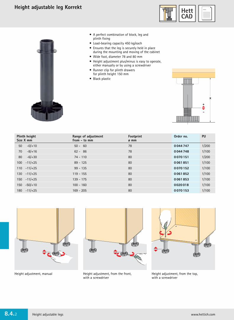
Height adjustable leg Korrekt
Height adjustable legs www.hettich.com8.4.2
� A perfect combination of block, leg and plinth fixing
� Load-bearing capacity 450 kg/each� Ensures that the leg is securely held in place
during the mounting and moving of the cabinet� Wide foot, diameter 78 and 80 mm� Height adjustment plus/minus is easy to operate,
either manually or by using a screwdriver� Runner clip for plinth drawers
for plinth height 150 mm� Black plastic
Height adjustment, manual Height adjustment, from the front, with a screwdriver
Height adjustment, from the top, with a screwdriver
x
Plinth height Range of adjustment Footprint Order no. PUSize X mm from - to mm ø mm
50 -0/+10 50 - 60 78 0 044 747 1/200
70 -8/+16 62 - 86 78 0 044 748 1/100
80 -6/+30 74 - 110 80 0 070 151 1/200
100 -11/+25 89 - 125 80 0 061 851 1/100
110 -11/+25 99 - 135 80 0 070 152 1/100
130 -11/+25 119 - 155 80 0 061 852 1/100
150 -11/+25 139 - 175 80 0 061 853 1/100
150 -50/+10 100 - 160 80 0020 018 1/100
180 -11/+25 169 - 205 80 0 070 153 1/100

Height adjustable legs 8.4.3
Fixing block for height adjustable leg Korrekt
• Screw-on version• Black plastic
• With 4 knock-in socketsand grip recesses
• Black plastic
• With 2 knock-in sockets• Black plastic
• With 2 expanding dowels/pins• With wide support
for side panel • Black plastic
Plinth clip
• For front plinths 12 - 16 mm • Not for use with the
screw-on type fixing block• Plastic, self-colour
Order no. PU
0 061 854 1/200
Order no. PU
0 047 654 1/40
Order no. PU
0 047 655 1/40
Order no. PU
0 079 689 1/40
Order no. PU
0 071 849 1/40
8064
6423,539,5 95
25
ø10
11,5
25
642139,5
92
64 80
ø15
12
25 80
39,595
64
ø15
13
6
9 x 45∞25
80
39,592
64
In case of adjustment fromthe top: 8 mm ø drill hole
Front plinth
Cabinet front edge
Side plinth blind
In case of adjustment from the top:8 mm ø drill hole
Front plinth
Cabinet front edge
Cabinet sideIn case of adjustment fromthe top: 8 mm ø drill hole
Cabinet side
Expanding dowel
Side plinth blind
Front plinth
Cabinet front edge
In case of adjustment fromthe top: 8 mm ø drill hole
Cabinet side
Cabinet side
Side plinth blind
Side plinth blind
Cabinet front edge
Front plinth
Plinth clip
Plinth clip
Plinth clip
Plinth clip
Plinth clip
Plinth clip

Plinth clip for height adjustable leg KorrektTurboClip drawer-front support
Height adjustable legs www.hettich.com8.4.4
3,2
6,3
Plinth
Groove dimension
�
�
TurboClip drawer-front support
• Toolless assembly• No screws or grooves• Constant spring tension• Universal application• Chrome plated steel
� Turbo-Clip F with handle element – for front plinths
� Turbo-Clip S – for side plinths
Installation requirement:
• Minimum thickness of plinth 12 mm• Top and bottom, plinth must rest against
leg (foot and block)
�
�
25
20
50
12
50
1220
25
Turbo Clip F –for front panels
Turbo Clip S –for side panels
Article Order no. PU
� Clip, groove version 0 073 481 1/200
� Clip, screw-on version 0 061 855 1/200
Article Order no. PU
� TurboClip F 0 079 690 1/20
� TurboClip S 0 079 691 1/20
!Plinth clipfor height adjustable leg Korrekt
• Groove version or screw-on version• Plastic, black/non-coloured• For plinth height from 70 mm

Height adjustable legs 8.4.5
Runner clip for Korrekt height-adjustable leg and roller runner system FR 302/402/602
• The runner clip can be used in combination with the heightadjustable leg Korrekt and the roller runner system FR 302/402/602
• Suitable for plinth height measurements of at least 150 mm• The runners are mounted to the runner clips
and then clipped onto the levelling feet• During this procedure, it is important to make sure
that the lower clamp of the runner clips is clicked into place on the levelling foot
• The bottom position of the drawer always remains the same even if the plinth height is adjusted.
• Roller runner system FR 302/402/602, see group 5• Black plastic
� Mount runners to the runner clips � Attach runner clip to legs � The now assembled unit is knocked into the fixing blocks, with the runnersfacing towards the inside. The rollers must be positioned at thefront.
� Locate drawer onto runners beneaththe cabinet
Order no. PU
0 070 154 1/20

Universal fixing block PlanformCorner solution in combination with Korrekt height-adjustable leg
Height adjustable legs www.hettich.com8.4.6
Universal fixing block Planform and height adjustable leg Korrekt
• The alternative system for attractive, relaxed corner fronts
• Angled and round plinths at any angle between 90 and 150 degrees can be fastened without any problems
• Front plinths are mounted quickly and easily, with no screws or grooves
• The stepping on the clips and fixing block presses the lip sealagainst the floor
• Can be disassembled completely by pulling out the expanding pins
• Efficiently sorted for recycling• The universal fixing block Planform can only be used
with the height adjustable leg Korrekt (see page 8.4.2)
Universal fixingblock Planform
Height adjustableleg Korrekt
Planform universal fixing block in combinationwith Korrekt height-adjustable leg
• ... creates freedom in modern kitchen front design • Planform enables you to get round any corners between 90 and
150 degrees. Awkward corner solutions are a thing of the past.• The glider is not visible from the front. The plinth makes a neat fit.
In addition, the lip seal is pressed down. That applies, whatever the angle!
• The secret of so many possibilities is in the stepping of the clip and fixing block. In combination with the height adjustable legKorrekt, Planform is unsurpassed - just like your design ideas.
• Planform can be dismounted completely and sorted for recycling

Height adjustable legs 8.4.7
Universal fixing block PlanformAccessories
Universal fixing block Planform with 3 expanding pins
• Black plastic
Universal fixing block Planformscrew-on version
• With overlay• Black plastic
Clips for front plinths
• For 19-mm front panel• Plastic, self-colour
Panel dowel
• For fastening the side panel• The panel dowel is pressed into
the Planform universal fixing block• Black plastic
Clips for front plinths
Attach the plinth clip to the groove in the fixing block
Now gently pull the panel clip away from the fixing block and slide it all the way into the groove
Note: Design the front plinth so that it is 4 mm lower than the leg height
Article Order no. PU
Planform with overlay 0 074 667 1/200
Planform without overlay 0 074 668 1/200
Order no. PU
0 079 693 1/200
Order no. PU
0 079 694 1/200
Order no. PU
0 074 671 1/200

Universal fixing block PlanformAssembly
Height adjustable legs www.hettich.com8.4.8
25
ø 10
25
ø 10
12
ø8
18
8,5
8 x 45∞
12
ø8
18
8,5
ø8 x 8,5
80
18
Leg distance
Planform without overlay
Note:
For fixing blocks with supportchamfer the front panel 8 x 45° at the top
64
1921
64
80
Cabinet side
Cabinet front edge
Cabinet side
Cabinet side
Side plinth blind
Side plinth blind
deep
Planform with overlay

Height adjustable legs 8.4.9
Height adjustable leg Korrekt/Universal fixing block Planform
Assembly
� Universal fixing block Planformwith 3 expanding pins
� Push Planform universalfixing block into the hole ...
� ... and knock in the expanding pins
�
Side plinth fastened in place byplinth dowel
� To dismantle the Planform universal fixing block, pull out the expanding pins
Clips for front panel
Side plinth dowel
Height adjustableleg Korrekt
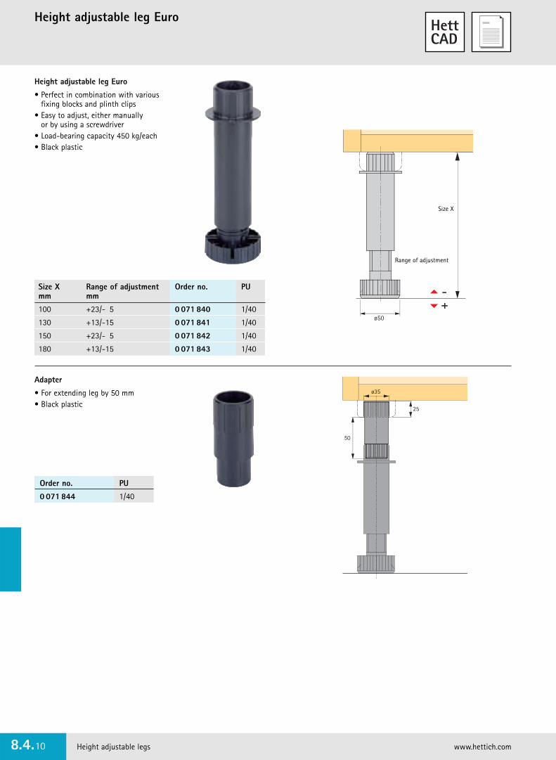
Height adjustable leg Euro
Height adjustable legs www.hettich.com8.4.10
Height adjustable leg Euro
• Perfect in combination with various fixing blocks and plinth clips
• Easy to adjust, either manually or by using a screwdriver
• Load-bearing capacity 450 kg/each• Black plastic
ø50
Range of adjustment
Size X
Size X Range of adjustment Order no. PUmm mm
100 +23/- 5 0 071 840 1/40
130 +13/-15 0 071 841 1/40
150 +23/- 5 0 071 842 1/40
180 +13/-15 0 071 843 1/40
Adapter
• For extending leg by 50 mm• Black plastic
ø35
25
50
Order no. PU
0 071 844 1/40

Height adjustable legs 8.4.11
Fixing block for height adjustable leg Euro
Order no. PU
0 071 847 1/40
Order no. PU
0 073 510 1/40
Order no. PU
0 071 849 1/40
Order no. PU
0 071 848 1/40
Fixing block, screw-on version
• Black plastic
27
ø50
7 x 45∞
58
25
Side plinth
Cabinet side
Countersunk screws ø 4 x 17 mm
ø25
7 x 45∞
ø50
27
25
58
Cabinet side
Side plinth
Design the front plinth so that it is 4 mm lower than the leg height
7 x 45∞
27
ø 4 x 7 mm
50
5025
12-16
Side plinth
Countersunk screws
Cabinet front Front panel
Fixing block, knock-in version
• For 25 mm hole diameter• Black plastic
Fixing block, screw-on version
• Black plastic
Plinth clip
• For front plinths 12 - 16 mm • Plastic, self-colour

Plinth clip for Euro legTurboClip drawer-front support
Height adjustable legs www.hettich.com8.4.12
TurboClip drawer-front support
• Toolless assembly• No screws or grooves• Constant spring tension• Universal application• Chrome plated steel
� TurboClip F with handle element – for front plinths
� TurboClip S – for side plinths
Installation requirement:
• Minimum thickness of plinth 12 mm• Top and bottom, plinth must rest against
leg (foot and block)
�
�
25
20
50
12
50
1220
25
TurboClip F –for front panels
TurboClip S –for side panels
Plinth clip for Euro height-adjustable leg
• Screw-on version• Plastic, black/white
Design the front plinth so that it is 4 mm lower than the leg height
12-16
4
ø 4 x 7 mm
Cabinet front Front panel
Countersunk screws
Side plinth
Order no. PU
0 071 845 1/40
Article Order no. PU
� TurboClip F 0 079 690 1/20
� TurboClip S 0 079 691 1/20

Height adjustable legs 8.4.13
Runner clip for Euro height-adjustable leg and roller runner system FR 302/402/602
• The runner clip can be used in combination with the height adjustable leg Euro and the roller runner system FR 302/402/602
• Suitable for plinth height measurements of at least 150 mm• The runners are mounted to the runner clips and
then clipped onto the levelling feet• During this procedure, it is important to make sure that the lower
clamp of the runner clips is clicked into place on the levelling foot• The bottom position of the drawer always remains the same
even if the plinth height is adjusted• Roller runner system FR 302/402/602, see group 5• Black plastic
� Mount runners to the runner clips � Attach runner clip to legs � The now assembled unit is knockedinto the fixing blocks, with the runners facing towards the inside. The rollers must be positioned at the front.
� Locate drawer onto runners beneaththe cabinet
Order no. PU
0 073 630 1/20

!
Height adjustable leg InnoTech with plinth drawer mounting
Height adjustable legs www.hettich.com8.4.14
• Perfect combination of height adjustable leg and plinth drawer mounting (e.g. InnoTech)
• Suitable for leg height measurements of at least 150 mm• Range of adjustment +22/-5 mm• Simple manual plus/minus height adjustment• Parallelism of plinth drawer and cabinet above it• Runner can be retrofitted• Installation height variable in 5 mm increments• Can be installed between all cabinets,
even when adjacent unit is a corner unit or oven unit• Load-bearing capacity 750 kg• Aluminium profile can be reduced in length
Set contains:4 legs, aluminium self-colour2 runners, steel8 countersunk screws, ø 4 mm4 screws ø 4,2 x 9,5 DIN 7981, for fixing the runner4 screws ø 4,8 x 9,5 DIN 7982, for fixing the runner (e.g. Quadro)
� �
� �
Assembly
Plinth height Range of adjustment Order no. PUmm mm
150 +22/-5 0 013 297 1 set
170 +22/-5 0 013 298 1 set
200 +22/-5 0 013 299 1 set
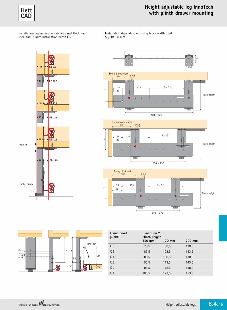
Height adjustable legs 8.4.15
Height adjustable leg InnoTech with plinth drawer mounting
Installation depending on cabinet panel thicknessused and Quadro installation width EB
Installation depending on fixing block width used50/80/100 mm
Flush fit
16 EB 12,5
16
16
18
19
16
EB 9,5
EB 12,5
EB 12,5
EB 10,5
EB 12,5
50
3437
260 - 320
128 5 x 32
ø 5,5
Y
80
3437
230 - 290
128 5 x 32
ø 5,5
Y
100
34
37
210 - 270
Y
ø 5,5
128 5 x 32
37
25
Fixing block width
Fixing block width
Fixing block width
Leveller screw
Plinth height
Plinth height
Plinth height
X 1X 2
X 3X 4
X 5X 6 Y
70
16
Y
36
9,5
InnoTech
Fixing point Dimension Ypunkt Plinth height
150 mm 170 mm 200 mm
X 6 78,5 98,5 128,5
X 5 83,5 103,5 133,5
X 4 88,5 108,5 138,5
X 3 93,5 113,5 143,5
X 2 98,5 118,5 148,5
X 1 103,5 123,5 153,5

Height adjustable leg Vista
Height adjustable legs www.hettich.com8.4.16
Recommended assembly for continuous construction
Height adjustable leg Vista
80,532
5,3 8,5
29
ø4 x 25
64 80,5
XX
Fixing block, screw-on version
• Decorative, visible leg designed for modern furniture without plinths• Concealed function, yet simple to adjust• Fixing block, screw-on version• Easy to install• Height can be adjusted easily, either manually or with the use
of a screw driver• Load-bearing capacity 450 kg/each• Completely recyclable, as all parts originate from one type of material• Silver-grey plastic
Fixing block, screw-on version
• For height adjustable leg Vista• Silver-grey plastic
Cover cap
Screw-on
fixing block
Countersunkscrew
± Adjustment, manual or with the use of a screwdriver
Precision adjustment by turning the cover cap
Size
Size X Range of adjustment Order no. PUmm mm
100 +15/- 5 0 079 696 1/40
150 +15/- 5 0 079 697 1/40
200 +10/-15 0 079 698 1/40
Order no. PU
0 079 699 1/40

Height adjustable legs 8.4.17
Drill-in adjustable leg Rigal
• For side thicknesses of 18 mm and over• Drilling diameter 14 mm• Height adjustment by means of 4 mm Allen key• Five different heights• Load-bearing capacity 300 kg/each• Zinc die-cast, self-colour
DimensionsTotal height 39,5 mm
DimensionsTotal height 66,5 - 154,5 mm
Total height Size H Height adjustment Order no. PUmm mm mm
39,5 25 +10 9 079 785 1/100
66,5 52 +25 9 079 786 1/100
84,5 70 +25 9 079 787 1/100
134,5 120 +25 9 079 788 1/100
154,5 140 +25 9 079 789 1/100
Drilling jig
• For height adjustable leg Rigal• Steel
Order no. PU
9 079 790 1
10
25
4,5
10
ø14
ø6
25
20
25
24
29
1,54
10
H
4,5
ø18
25
ø6
ø14
ø18
1,5
min. 18 min. 18
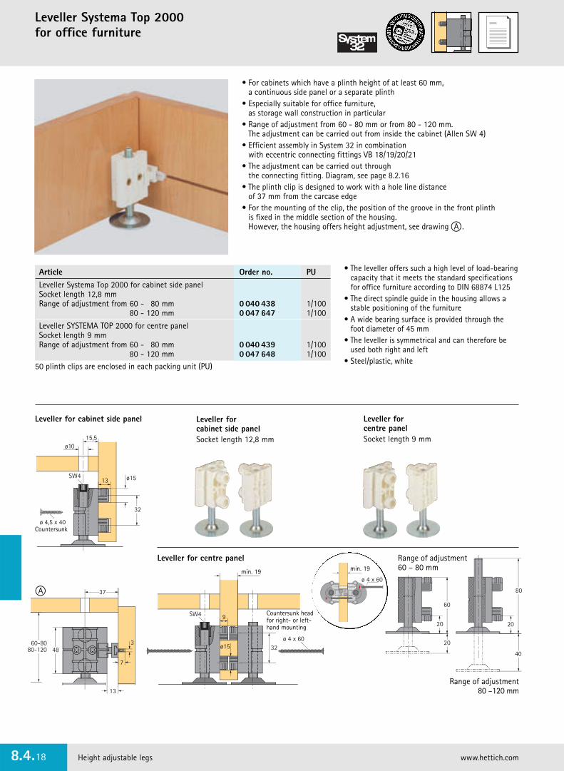
Leveller Systema Top 2000 for office furniture
Height adjustable legs www.hettich.com8.4.18
• For cabinets which have a plinth height of at least 60 mm, a continuous side panel or a separate plinth
• Especially suitable for office furniture, as storage wall construction in particular
• Range of adjustment from 60 - 80 mm or from 80 - 120 mm.The adjustment can be carried out from inside the cabinet (Allen SW 4)
• Efficient assembly in System 32 in combinationwith eccentric connecting fittings VB 18/19/20/21
• The adjustment can be carried out through the connecting fitting. Diagram, see page 8.2.16
• The plinth clip is designed to work with a hole line distance of 37 mm from the carcase edge
• For the mounting of the clip, the position of the groove in the front plinth is fixed in the middle section of the housing. However, the housing offers height adjustment, see drawing A .
• The leveller offers such a high level of load-bearingcapacity that it meets the standard specificationsfor office furniture according to DIN 68874 L125
• The direct spindle guide in the housing allows astable positioning of the furniture
• A wide bearing surface is provided through thefoot diameter of 45 mm
• The leveller is symmetrical and can therefore beused both right and left
• Steel/plastic, white
Leveller for cabinet side panel
Leveller for centre panel
50 plinth clips are enclosed in each packing unit (PU)
ø 4,5 x 40
32
ø1513SW4
15,5ø10
37
3
7
13
4860-80
80-120
60
20
20
Range of adjustment60 – 80 mm
Countersunk
Leveller for cabinet side panelSocket length 12,8 mm
Leveller for centre panel Socket length 9 mm
A
SW4
32
min. 19
ø15
9
ø 4 x 60
ø 4 x 60
min. 19
Countersunk headfor right- or left-hand mounting
Range of adjustment80 –120 mm
min. 19 min. 19
Article Order no. PULeveller Systema Top 2000 for cabinet side panelSocket length 12,8 mmRange of adjustment from 60 - 80 mm 0 040 438 1/100
80 - 120 mm 0 047 647 1/100
Leveller SYSTEMA TOP 2000 for centre panelSocket length 9 mmRange of adjustment from 60 - 80 mm 0 040 439 1/100
80 - 120 mm 0 047 648 1/100
20
80
40

Height adjustable legs 8.4.19
Leveller screws with accessories
Leveller screw M8
• With foot cap • Chrome plated steel/plastic, self colour
T-nut M8
• Steel self-colour
Supporting plate M8
• Chromated steel
Metal bracket M8
• Chromated steel
6
M8
ø30
5
ø32
X
ø22 ø9,5
M8
60
40 10
20
305,5
M83
20,5
ø12,4
M8
2937
40ø5,4
5,5 26
12
16
20,5
Size
Size X mm Order no. PU
50 0 047 637 1/50
60 0 047 638 1/50
70 0 047 639 1/50
80 0 047 640 1/50
100 0 047 642 1/50
Order no. PU
0 047 643 1/50
Order no. PU
0 047 645 1/50
Order no. PU
0 047 644 1/ 50
0 071 870 1/500
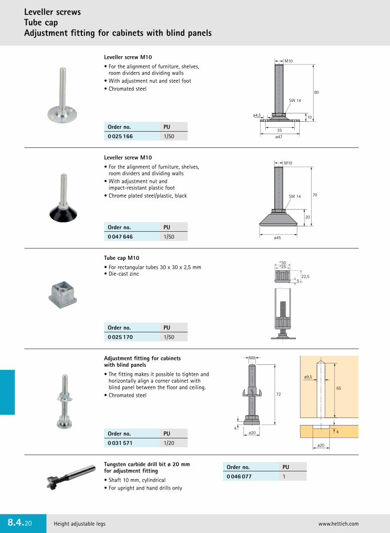
Leveller screwsTube cap Adjustment fitting for cabinets with blind panels
Height adjustable legs www.hettich.com8.4.20
Leveller screw M10
• For the alignment of furniture, shelves,room dividers and dividing walls
• With adjustment nut and steel foot• Chromated steel
Leveller screw M10
• For the alignment of furniture, shelves,room dividers and dividing walls
• With adjustment nut and impact-resistant plastic foot
• Chrome plated steel/plastic, black
Tube cap M10
• For rectangular tubes 30 x 30 x 2,5 mm• Die-cast zinc
M10
SW 14
20
ø45
70
M10
SW 14
ø4,5
35ø47
10
80
30
5
25
22,5
4ø20
M8
72
ø9,5
4
65
ø20
Adjustment fitting for cabinets with blind panels
• The fitting makes it possible to tighten and horizontally align a corner cabinet with blind panel between the floor and ceiling.
• Chromated steel
Order no. PU
0 025 166 1/50
Order no. PU
0 047 646 1/50
Order no. PU
0 025 170 1/50
Order no. PU
0 031 571 1/20
Tungsten carbide drill bit ø 20 mm for adjustment fitting
• Shaft 10 mm, cylindrical • For upright and hand drills only
Order no. PU
0 046 077 1

Shelf supports and shelf-support strips/folding support brackets 8.5.1
Range summary8.5 Shelf supports and shelf-support strips/folding support bracketsi
Shelf supports
8.5.2 - 8.5.5
Shelf support rails
8.5.6 - 8.5.8
Decorative shelf supports
8.5.9 - 8.5.12
Folding brackets
8.5.13 - 8.5.14

Shelf supports
Shelf supports and shelf-support strips/folding support brackets www.hettich.com8.5.2
8
4 ø3/4/5/6
8
8
12,5ø5
12
ø5
8
5
ø5
8
5
7,5 ø5
10
ø5
Shelf support Safety
• Steel pin, housed in moulded plastic
Shelf support Universal 1
• Pin diameter 5 mm• 1 additional pin for shelf• Nickel-plated/die-cast zinc
Shelf support Sekura 2
• Pin diameter 5 mm• Nickel-plated/die-cast zinc
Shelf support Sekura 6
• Pin diameter 5 mm• 1 additional pin for shelf• Nickel-plated/die-cast zinc
ø5
7
Shelf support
• Pin diameter 5 mm• White plastic
Pin diameter Finish Order no. PUmm
5 white 0 025 090 1/500
brown 0 025 091 1/500
beige 0 025 092 1/500
translucent 0 016 180 1/500
6 translucent 0 022 532 1/500
4 translucent 0 022 533 1/500
3 translucent 0 022 534 1/500
Order no. PU
0 019 557 1/500
Order no. PU
0 079 707 1/500
Order no. PU
0 025 100 1/500
Order no. PU
0 044 751 1/500

Shelf supports and shelf-support strips/folding support brackets 8.5.3
Shelf supports
Order no. PU
0 022 737 1/500
Order no. PU
0 047 609 1/500
Shelf support Sekura 7� Hole diameter 5 mm for Euro screw,
countersunk head diameter 6,3 mm� Hole diameter 3 mm for countersunk screw dia. 4 mm • Each contains 1 additional pin for shelf• Nickel-plated/die-cast zinc
8ø3
12ø5
12,5
8ø5
12ø5
12,5
� �
Shelf support Universal D
• Pin diameter 5 mm• Nickel-plated/die-cast zinc
8
2
ø5
Shelf support Sekura 8
• Pin diameter 5 mm• With glass shelf support • Nickel-plated/die-cast zinc/transparent
Order no. PU
0 073 615 1/500
Glass shelf support
• With tilt prevention • Pin diameter 5 mm• plastic, translucent
8
5
ø5
Order no. PU
9 080 214 1/500
Glass shelf support
• To prevent accidental removal or tilting
• For 4 - 8 mm glass thickness• Nickel-plated zinc die-cast
ø5
8
4 - 83,2
12 22
1
Assembly Disassembly
2,5
ø5
7,5max. 6
Hole diameter Order no. PUmm
� 5 0 053 012 1/500
� 3 0 079 711 1/500

Shelf supports and shelf-support strips/folding support brackets www.hettich.com8.5.4
Shelf supports
Push-in shelf support
• ø 5 x 24 mm• Chromated steelø5
2,5
24
Push-in shelf support
• Pin diameter 5 mm• Chromated steel
3,758
ø5
Shelf support Duplo
• Pin diameter both sides 5 mm • Steel
8ø5
ø5
0,5
Glass shelf support
• With plastic cover cap• Soft plastic support prevents shelf
from rattling• Steel pin, chrome plated
Plastic, transparent
8
ø3/5
Flattened shelf support
• For hole line ø 5 mm• Chromated steel
8
ø5
10,5
ø8
Order no. PU
0 025 124 1/500
Order no. PU
0 016 181 1/500
Order no. PU
0 020 782 1/500
Finish Order no. PU
nickel-plated 0 046 642 1/500
chrome-plated 0 013 138 1/500
Artikel Finish Order no. PU
Shelf support brass-plated 0 025 200 1/500
nickel-plated 0 025 201 1/500
Sleeve brass-plated 0 025 202 1/500
nickel-plated 0 025 203 1/500
Pin diameter Order no. PUmm
5 0 079 709 1/500
3 0 079 710 1/500
Flattened shelf support with sleeve
• Pin diameter 8 mm• Steel

Shelf supports and shelf-support strips/folding support brackets 8.5.5
Shelf supports
Shelf support Perfekt F
• With steel pin • Plastic
Two part shelf support VB 52 D• The support part, which is made of
die-cast zinc, is mounted to the cabinet
• The shelf is securely tightened to thecabinet side by the cone-shaped guide
• Nickel-plated/die-cast zinc16-19 12,7ø5
8
12,56,5
ø15
5
10
Shelf support
• For grooved shelves• Pin diameter 5 mm• Zinc, self-colour
8
12-15
8
ø5Shelf studs
• Pin diameter 5 mm• Plastic, translucent
Finish Order no. PU
white 0 013 130 1/500
brown 0 013 131 1/500
Article Order no. PU
ø 6,3 x 14 mm 0 047 452 200
ø 6,3 x 18 mm 0 052 799 200
Order no. PU
0 047 662 1/500
Order no. PU
0 074 805 1/500
Order no. PU
0 063 549 1/500
Euro screw, countersunk head
8,5
ø5
8

Shelf support strip Vari Alu 11 x 6 mmand shelf support
Shelf supports and shelf-support strips/folding support brackets www.hettich.com8.5.6
� Shelf support strip Vari Alu 11 x 6 mm with 25 mm spacing
• Standard length 3500 mm• Aluminum, self-colour or gold anodised
� Shelf support Vari Alu 11 mm
• Aluminum, self-colour or gold anodised
7
12,9
5,6
11 x 6 mm
25
3
18
10
�
�
Groove
Finish Order no. PU
self-colour 0 029 246 30
gold anodised 0 029 248 30
Finish Order no. PU
self-colour 0 029 249 1/250
gold anodised 0 029 251 1/250

Shelf supports and shelf-support strips/folding support brackets 8.5.7
Shelf support strip Vari 10 x 5 mmand shelf support
� Shelf support Vari 10 mm
• Steel, brass plated or chrome plated
Finish Order no. PU
brass-plated 0 047 611 50
nickel-plated 0 047 612 50
Finish Order no. PU
brass-plated 0 013 126 1/250
chrome-plated 0 013 127 1/250
� Shelf support strip Vari 10 x 5 mm with 15 mm spacing
• Standard length 3500 mm• Steel, brass plated or nickel plated
6
5
10
1
8,75
15
6 x 15 mm 105
2,5
1
18
9
10
�
�
Mounting with countersunk wood screws

Shelf support strip Vari 16 x 6 mmand shelf support
Shelf supports and shelf-support strips/folding support brackets www.hettich.com8.5.8
� Shelf support strip Vari 16 x 6 mm with 14 mm spacing
• Standard length 3500 mm• Steel, brass plated or nickel plated
� Shelf support Vari 16 mm
• Steel, brass plated or chrome plated
Finish Order no. PU
brass-plated 0 047 613 50
nickel-plated 0 047 614 50
Finish Order no. PU
brass-plated 0 013 128 1/250
chrome-plated 0 013 129 1/250
9,5 3
8,5
14
986 x 14 mm
6
16
1,5
1,5
25,5
11,5
14
�
�
Mounting with countersunk wood screws

Guidelines for mounting in relation to the load-bearingcapacity
• Use the enclosed dowels and screw bolts only for the illustrated types of stone blocks
• With regard to other types ofwall materials, use only the special mounting fixtures whichare commercially available foreach material
Shelf supports and shelf-support strips/folding support brackets 8.5.9
Glass shelf support Base
A
B
Set A contains:
Set B contains:
X
201
2
201
ø8
16-22
� � � �
1 pcs 1 pcs 1 pcs 1 pcs
� �
�
�
Height adjustment ± 1,5
Wall structures and materials vary. If in doubt, seek professional advice.
�
d
a
a = 50d = 175
1 K Hbl
d
a
a = 60d = 300
a = 50d = 240/300
2 K Hbl
d
a
a = 35d = 240/300/365
3 K Hbl
X
X
X
Finish Article Article PU
chrome-plated matt 0 074 659 0 074 662 1 set
high-gloss chrome-plated 0 074 661 0 074 664 1 set
• Sturdy all-metal design – ideal for use in the kitchen, living room and bathroom
• Two rubber rings to prevent vibration• Integrated height adjustment ±1,5 mm• Load-bearing capacity of 50 kg/m2 with even load distribution
A B
� � � �
1 pcs 1 pcs 1 pcs 1 pcs 1 pcs
� � �

Decorative shelf supports Sailor
Shelf supports and shelf-support strips/folding support brackets www.hettich.com8.5.10
• Decorative shelf and glass-shelf supportfor any area in the home
• For shelf thickness up to 30 mm thick• Easy to install• Versatile when combined and used with shelf materials
such as wood, plastic, glass, stainless steel• Maximum load capacity, refer to table
Set contains: 2 shelf supports with full set of fixing material
* Total loads are for the support spacings indicated and assume even weight distribution and wall ofsufficient load-bearing capacity
Shelf support Sailorwith glass shelf
Shelf support Sailor with wooden shelf
max. 600
max. 300
max. 30
73
100
40 105
29
max. 20
50
48
55
max. 26
30
55
70
75
Assembly
Decorative shelf supports Sailorfor shelf thickness measurement of 2 - 30 mm
� Decorative shelf supports Sailorfor shelf thickness measurement of 2 - 26 mm
� Decorative shelf supports Sailor forshelf thickness measurement of 2 - 20 mm
max. 20 max. 26max. 30
Finish � for shelf thickness � for shelf thickness � for shelf thickness PUmeasurement of 2 - 20 mm measurement of 2 - 26 mm measurement of 2 - 30 mmshelf depth max. 150 mm shelf depth max. 200 mm shelf depth max. 300 mmsupport spacing 300 mm support spacing 450 mm support spacing 600 mmmax. loading capacity* 8 kg max. loading capacity* 12 kg max. loading capacity* 18 kg
high-gloss chrome-plated 0 070 417 0 070 422 0 070 427 1 set
stainless steel finish 0 070 418 0 070 423 0 070 428 1 set
white 0 070 419 0 070 424 0 070 429 1 set

25%
50%
25%
5%
50%
Shelf supports and shelf-support strips/folding support brackets 8.5.11
Shelf supports Titan/Titan 1
Shelf supports Titan
• Concealed shelf mounting• Max. load with 2 shelf supports including shelf 9 kg• Bolt: SW 10 mm• Height adjustment: ± 4 mm• Minimum shelf thickness: 24 mm• Shelf angle adjustment • Zinc-plated steel
Shelf supports Titan 1
• Concealed shelf mounting• Max. load with 2 shelf supports including shelf 9 kg• Bolt: SW 10 mm• Height adjustment: ± 4 mm• Side adjustment: ± 4 mm• Minimum shelf thickness: 24 mm• Shelf angle adjustment • Zinc-plated steel
min. 115
1280
20
12
min. 24±4
SW 10
100
54
Special screwPanhead 5,5 x 50
min. 115
min.
min. 115
1290
20
12
min. 24
±4
±4
SW 10
100
54
Special screwPanhead 5,5 x 50
min. 115
min.
Order no. PU
0 047 661 1/20
Order no. PU
0 079 713 1/20
Order no. PU
0 065 480 1/100
25%
50%
25%
5%
50%
Special screw ø 5,5 x 50 mm
• Panhead• Chromated steel
Dowel ø 8 x 40 mm
• Plastic, self-colour
max. 300
max. 1000
max. 300
max. 1000

min. 105
12,580
20
12
min. 24±4
90
54
Special screwPanhead 5,5 x 50
min. 105
min.
min. 105
12,580
17
12
min. 19±2
90
54
Special screwPanhead 5,5 x 50
min. 105
min.
Shelf supports Titan 2/Titan 3
Shelf supports and shelf-support strips/folding support brackets www.hettich.com8.5.12
25%
50%
25%
5%
50%
Shelf supports Titan 2
• Concealed shelf mounting• Max. load with 2 shelf supports including shelf 9 kg• Bolt: ø 12 mm• Height adjustment: ± 4 mm• Minimum shelf thickness: 24 mm• Shelf angle adjustment • Zinc-plated steel
Shelf supports Titan 3
• Concealed shelf mounting• Max. load with 2 shelf supports including shelf 9 kg• Bolt: ø 12 mm• Height adjustment: ± 2 mm• Minimum shelf thickness: 19 mm• Shelf angle adjustment • Zinc-plated steel
Order no. PU
0 063 598 1/20
Order no. PU
0 079 714 1/20
Order no. PU
0 065 480 1/100
25%
50%
25%
5%
50%
Special screw ø 5,5 x 50 mm
• Panhead• Chromated steel
Dowel ø 8 x 40 mm
• Plastic, self-colour
max. 300
max. 1000
max. 300
max. 1000

Shelf supports and shelf-support strips/folding support brackets 8.5.13
Folding brackets
Order no. PU
0 073 605 1
0 073 606 1
0 073 607 1
0 073 608 1
• High-quality aluminium table flap stay• Tables and shelves fold down to save space
in confined areas• Aluminium
Hinge mounting for high loads
For high loads mount the hinge on top.
A
B
C
P1
P2
The space saver:
Fold down table flap to gain space.
Simple and safe:
Lift the top slightly and slide the safety device over the outer section.
Order no. SizeA mm B mm C mm P1 kg P2 kg
0 073 605 20 - 30 150 14 60 30
0 073 606 25 - 39 252 45 95 55
0 073 607 25 - 50 402 87 120 60
0 073 608 25 - 40 549 137 140 80

Folding brackets
Shelf supports and shelf-support strips/folding support brackets www.hettich.com8.5.14
H
L 30
• Enable tables and shelves to fold down to save space in confined areas
• With cross-bar to increase load capacity• Steel, white lacquered
�
�
Size Load capacity* Order no. PUL mm H mm kg/pcs
315 310 55 0 001 102 1
430 410 60 0 001 103 1
*Notes to the load capacity!
The quoted load capacity is guaranteed if the long arm is mounted on the wall. We have no control over the material or nature of the wall, support or fastening. These should be matched to the load capacity.

Cabinet suspension brackets 8.6.1
Range summary8.6 Cabinet suspension bracketsi
Cabinet suspension brackets SAH 215/216for use behind the rear panel
8.6.2 - 8.6.3
Cabinet suspension bracket SAH 130, knock-in
8.6.4
Cabinet suspension brackets SAH 14/16, screw on
8.6.5
Cabinet suspension bracket SAH 5, knock-in
8.6.6
Spacers for horizontalalignment of wall units
8.6.6
Suspension rails/hooksfor cabinet suspension brackets
8.6.7
!

Cabinet suspension brackets SAH 215 / 216
Cabinet suspension brackets www.hettich.com8.6.2
• For use behind the rear wall• SAH 216 – for additional top panel mounting• For rail and hook suspension• Load-bearing capacity 65 kg/each• Mounted by 3 pins into the side panel,
additional screw connection is also possible• Suitable for back panel recess measuring at least 16 mm• Quick, convenient height adjustment through
a sturdy adjustment screw and gear: ± 8 mm• Depth adjustment: max. 25 mm• Lateral adjustment ± 3 mm if hook suspension is used• Adjustment screws are secured against unintentional removal • Lift-off height: 7,5 mm• Hook suspension: the closed form of the hook
prevents the cabinet from slipping off• Can be used with suspension rail Type B – see page 8.6.7• Zinc-plated, steel - fully recyclable
Screw connection in the top panel with wood screw 3,5 x 30
Depth adjustment max. 25 mm
Height adjustment ± 8 mm
Screw connection in the cabinet sidepanel with wood screw 3,5 x 20
STEEL RECYCLING
SAH 215 SAH 216 – for top panel mounting
Cover caps for SAH 215/216
• Plastic
Accessories/guidelines on the load-bearing capacity of cabinet suspension brackets – see page 8.6.7
Article Order no. PU
SAH 215 0 079 716 1/25 sets
SAH 216 0 079 717 1/25 setsfor top panel mounting
Finish Order no. PUø 12 mm ø 15 mm
white 0 079 718 0 079 719 1/50
silver-grey 0 079 722 0 079 723 1/50
!

Cabinet suspension brackets 8.6.3
Cabinet suspension brackets SAH 215 / 216Assembly
±3
R
30
R
30
143
min. 16
5032
32
min. 16
5
4
50
ø10
12,5min. ø12
19
R
30
R
159
min. 16
50
8
30
±3
56
32
32
min. 16
5
4
50
ø10
12,5min. ø12
19
16
24,5 8
Cabinet suspension bracket SAH 215
Cabinet suspension bracket SAH 216
Hook suspension Rail suspension
Hook suspension Rail suspension
SAH 215
SAH 215
SAH 216
SAH 216
Mounting variants
Attention:
If there is no top panel connection,then the SAH 215/216 must be mounted in the upper third of the cabinet height!with
top panel mounting
can be mounted in
variable positions in
the cabinet side panel
can be mounted in
variable positions in
the cabinet side panel
for continuous
top panel
min.
min.
min.
min.
min.
min.

Cabinet suspension bracket SAH 130, knock-in
Cabinet suspension brackets www.hettich.com8.6.4
• For rail and hook suspension• Load capacity 55 kg/each according to DIN 68840• Adjustment possibilities :
Height: ± 7 mmDepth: max. 15 mm, through patented depth adjustment screw Lateral adjustment: ± 3 mm if hook suspension is used
± 7 mm if rail suspension is used• Patented, threadless depth adjustment screw shoulder for
reliable installation• The adjustment screws are secured against unintentional removal• Lift-off height: 7,5 mm• Safe technology in attractive design: cover cap in 3 finishes;
design prize awarded• Hook suspension: the closed form of the hook
prevents the cabinet from slipping off• Steel/plastic, white
Cover caps for SAH 130
• Plastic
Depth adjustment up to 15 mm
2 moulded sockets, knock-in version (diameter 10 mm)
For hook suspension: lateraladjustment ± 3 mm
Height adjustment up to 14 mm
±7
23,7
29
18
ø10
31
16 3220,5
31
16 3220,5
±311
Adjustment possibilities Assembly
Hook suspension Rail suspension
Order no. PU
0 079 724 1/25 sets
Finish Order no. PU
white 0 079 725 1/25 sets
silver-grey 0 079 726 1/25 sets
beech 0 079 727 1/25 sets
Accessories/guidelines on the load-bearing capacity of cabinet suspension brackets – see page 8.6.7
max. 15

!
Cabinet suspension brackets 8.6.5
Cabinet suspension brackets SAH 14/16, screw on
Order no. PU
0 045 062 1/50
Accessories/guidelines on the load-bearing capacity of cabinet suspension brackets – see page 8.6.7
16
42
19
±3
15
3217
10 58
11
16 321716
ø4
SAH 14 screw on
• General-purpose hooks for rail and hook suspension• Load-bearing capacity 55 kg/each• Adjustment possibilities :
Height: ± 7 mmDepth: 10 mmLateral adjustment: ± 3 mm if hook suspension is used,
± 7 mm if rail suspension is used• Hook suspension: the closed form of the hook
prevents the cabinet from slipping off• Cabinet suspension brackets for right/left-hand use• Steel/plastic, white
Hook suspension Rail suspension
Adjustment possibilities Assembly
4030
22326,5
31
min.15,5 326,5
31
min. 15,5 326,5
11±3
54 54
±7
±7
Hook suspension Rail suspension
Adjustment possibilities Assembly
min. min.
SAH 16 screw on
• General-purpose hooks for rail and hook suspension• Load-bearing capacity 60 kg/each• Adjustment possibilities :
Height: ± 7 mmDepth: 15 mmLateral adjustment: ± 3 mm if hook suspension is used,
± 7 mm if rail suspension is used• Hook suspension: the closed form of the hook
prevents the cabinet from slipping off• Nickel-plated steel
Order no. PU
0 019 476 1/25 sets
max. 15
max. 15
19

Cabinet suspension bracket SAH 5Spacers for horizontal alignment of wall units
Cabinet suspension brackets www.hettich.com8.6.6
Cabinet suspension bracket SAH 5, knock-in
• Load-bearing capacity 20 kg/each• The suspension bracket
is knocked into a 30 mm dia. Hole• Zinc die-cast, self-colour
11,5
ø30
Spacers
• For horizontally aligning wall units• Adjustable range from 15 to max. 25 mm• The back wall recess must
be not less than 15 mm• No need to drill the back panel• Simple assembly: Just remove the backing film
and stick the spacer to the back panel. For additional security, the spacer can be fastened with 2 flat head screws dia. 4 x 17 on the 32 grid system.
• Black plastic
min. 15 mmmax. 25 mm
Ø 30
32
42
Flat head screw ø 4 x 17
Assembly
min. 15 mmmax. 25 mm
Order no. PU
0 040 669 1/100
Order no. PU
0 020 784 1/100

!
Cabinet suspension brackets 8.6.7
Suspension rails/hooksfor cabinet suspension brackets
Suspension rail Type B
• Load-bearing capacity 150 kg/cabinet• Mounting with 2 special screws dia. 5,5 x 50 mm per cabinet;
for total cabinet shelf areas measuring 1 sqm and more, with 4 special screws dia. 5,5 x 50 mm per cabinet
• Length 3000 mm with oblong holes, spacing 50,8 mm• Zinc-plated steel
Custom lengths by request
3000
286,2
4,5
817,5
1,75
50,8
Suspension rail Type L
• Load-bearing capacity 130 kg/each• The laterally interlocked ends of the suspension rail prevent the
cabinet from slipping off.• Length 130 mm with oblong holes, spacing 71 mm• Zinc-plated steel
130
50
35 ø5,5
4,5
816,5
2
3
71
In relation to the load-bearing capacity of cabinet suspensionbrackets and accessories, the following rules must be observed:1. The aspects pertaining to furniture construction as well as the
material and manufacturing quality of the furniture are beyondour sphere of influence.
2. In the same way, we also do not have any influence on the quality of the wall materials.
3. The screw hooks which we have supplied in combination withthe dowels are intended for use in solid bricks, sand-lime bricks,concrete blocks or clinker bricks. In the solid brick material, ahole with a diameter of 8 mm must be made and the plasticdowel must be knocked into this hole at flush level.
The minimum hook screw-in depth corresponds to the hooklength minus 10 mm.
4. With regard to mounting to other types of wall materials, the special fixings which are commercially available for eachmust be used.
5. For wall cabinets with more than 1 sqm of total base area(shelves, top panels and bottom panels), suspension is to be carried out by using suspension rails which must then be screwed on with a minimum number of 4 special screws.
6. Attachments, such as end shelves, must not be fitted withoutsuspension.
Guidelines for the load-bearing capacity of cabinet suspension brackets and accessories
Order no. PU
0 025 099 1/50
� Suspension hook ø 6 x 50 mm• Hook driver for cordless screwdriver
with hexagon receiver see page 2.4.4• Zinc-plated steel• Hook driver for suspension hook see page 2.4.4
� Special screw ø 5,5 x 50 mm• Panhead for rail mounting• Chromated steel
� Dowel ø 8 x 40 mm• Plastic, self-colour
Order no. PU
9 007651 10
Article Order no. PU� Suspension hook and� Dowel 0 046 103 1/100
� Special screw and� Dowel 0 065 480 1/100

Furniture glides
Furniture glides/Buffers/Furniture levelling wedges www.hettich.com8.7.0
Plastic furniture glide with knock-in pin• To be bored first with a 1 mm drill• White plastic
Metal furniture glide with knock-in pin• To be bored first with a 1 mm drill• Nickel-plated steel
Felt furniture glide with knock-in pin and plastic housing• To be bored first with a 1 mm drill• Synthetic felt, grey• Housing plastic, natural or brown• Not suitable for parquet
Felt parquet glide, screw-on version, with metal housing• To be bored first with a 2 mm drill• Wool felt grey/nickel-plated steel
ø
21
5
4
ø18
19
ø
2344
ø
29
6,53,5
ø mm Order no. PU
18 0 041 807 1/200
20 0 041 808 1/200
22 0 041 809 1/200
25 0 041 811 1/200
ø mm Order no. PU
17 0 041 846 1/100
22 0 041 847 1/100
25 0 042 284 1/100
28 0 042 285 1/100
ø mm Order no. PU
20 0 041 833 1/100
24 0 041 834 1/100
28 0 041 835 1/100
ø mm Order no. PUself-colour brown
17 0 041 822 0 041 827 1/200
20 0 041 824 0 041 828 1/200
24 0 041 825 0 041 831 1/200
Order no. PU
0 041 812 1/100
Felt slide round, self-adhesive• Felt thickness approx. 4,5 mm• White ø
4,5
200
100
4,5
Colour Order no. PU
white 0 002 264 1 set
brown 0 002 263 1 set
Felt pre-cut, self-adhesive• Approx. 100 x 200 mm • Felt thickness approx. 4,5 mm• White or brownSet contains: 5 felt pre-cuts

Furniture glides/Buffers/Furniture levelling wedges 8.7.1
BuffersFurniture levelling wedges
ø Height Order no. PUmm mm
13 4 0 041 841 100
13 6,5 0 041 839 100
19 4,5 0 041 837 100
ø Height Order no. PUmm mm
11 5 0 041 842 100
16 8 0 041 838 100
Width x depth x height Order no. PUmm
10 x 10 x 2,5 0 041 843 100
13 x 13 x 3 0 041 844 100
13 x 13 x 5,5 0 041 845 100
Order no. PU
0 041 836 100
Order no. PU
0 025 438 1/100
Buffer, self-adhesive• Transparent plastic
Buffer, self-adhesive• Transparent plastic
Buffer, self-adhesive• Transparent plastic
Buffer, self-adhesive
• ø 22 mm• Height: 9,5 mm• Transparent plastic
ø13
4
ø13
6,5
ø19
4,5
ø11
5 8
ø16
2,5
10 13
3
13
5,5
9,5
ø22
Plastic furniture levelling wedges
• Consisting of 8 wedges• With equal height increments of 1 - 8 mm• Brown plastic

www.hettich.com8.7.2