802sc base linexxxxxxxx03.08 xx - · pdf filesafety guidelines this manual contains notices...
TRANSCRIPT
Operation and Programming 08/2003 Edition
sinumerikSINUMERIK 802S base line SINUMERIK 802C base line Turning


Introduction 1
Turning On, ReferencePoint Approach 2
Setting Up 3
Manually Controlled Mode 4
Automatic Mode 5
Part Programming 6
Services and Diagnosis 7
Programming 8
Cycles 9
SINUMERIK 802S base lineSINUMERIK 802C base line
Operation and ProgrammingTurning
����������������������������������������������������������������������������������������������������
�����������������������������������������������������������������������������������������������������
������������������������������������������������������������������������������������������������������
Valid for
Control system Software versionSINUMERIK 802S base line 4SINUMERIK 802C base line 4
2003.08 Edition

SINUMERIK Documentation
Key to editions
The editions listed below have been published prior to the current edition.
The column headed “Note” lists the amended sections, with reference to the previous edition.
Marking of edition in the “Note” column:
A ... ... New documentation.B ... ... Unchanged reprint with new order number.C ... ... Revised edition of new issue.
Edition Order No. Note
1999.02 6FC5598-2AA00-0BP1 A2000.04 6FC5598-3AA00-0BP1 A2002.01 6FC5598-3AA00-0BP2 C2003.08 6FC5598-4AA01-0BP0 A
Trademarks
SIMATIC®, SIMATIC HMI®, SIMATIC NET®, SIMODRIVE®, SINUMERIK®, and SIMOTION® are registeredtrademarks of SIEMENS AG.
Other names in this publication might be trademarks whose use by a third party for his own purposes may violatethe registered holder.
Copyright Siemens AG 2003. All right reserved
The reproduction, transmission or use of this document or its con-tents is not permitted without express written authority. Offenders willbe liable for damages. All rights, including rights created by patentgrant or registration of a utility model, are reserved.
Exclusion of liability
We have checked that the contents of this document correspond tothe hardware and software described. Nonetheless, differencesmight exist and we cannot therefore guarantee that they are com-pletely identical. The information contained in this document is re-viewed regularly and any necessary changes will be included in thenext edition. We welcome suggestions for improvement.
© Siemens AG, 2003Subject to technical changes without notice.
Siemens-Aktiengesellschaft. SINUMERIK 802S/802C base line
®

Safety Guidelines This Manual contains notices intended to ensure your personal safety , as wellas to protect products and connected equipment against damage. Safetynotices are highlighted by a warning triangle and presented in the followingcategories depending on the degree of risk involved:
Danger
Indicates an imminently hazardous situation which, if not avoided, will result indeath or serious injury or in substantial property damage.
Warning
Indicates a potentially hazardous situation which, if not avoided, could result indeath or serious injury or in substantial property damage.
Caution
Used with safety alert symbol indicates a potentially hazardous situation which,if not avoided, may result in minor or moderate injury or in property damage.
Caution
Used without safety alert symbol indicates a potentially hazardous situationwhich, if not avoided, may result in property damage.
Notice
Indicates important information relating to the product or highlights part of thedocumentation for special attention.
Qualified person The unit may only be started up and operated by qualified person or persons.Qualified personnel as referred to in the safety notices provided in thisdocument are those who are authorized to start up, earth and label units,systems and circuits in accordance with relevant safety standards.
Proper use Please observe the following:
Warning
The unit may be used only for the applications described in the catalog or thetechnical description, and only in combination with the equipment, componentsand devices of other manufacturers as far as this is recommended or permittedby Siemens.
This product must be transported, stored and installed as intended, andmaintained and operated with care to ensure that it functions correctly andsafely.
!
!
!
!


Contents
SINUMERIK 802S/C base line IOperation and Programming Turning
ContentsSINUMERIK 802S/C base line Operator Panel OP III
1. Introduction 1-1 1.1 Screen Layout 1-1
1.2 Operating areas 1-41.3 Overview of the most important softkey functions 1-51.4 Pocket calculator 1-61.5 Coordinate systems 1-10
2. Turning On and Reference Point Approach 2-1 3. Set Up 3-1
3.1 Entering tools and tool offsets 3-13.1.1 Creating a new tool 3-33.1.2 Tool compensation data 3-43.1.3 Determining the tool offsets 3-53.2 Entering/modifying the zero offset 3-73.2.1 Determining the zero offset 3-83.3 Programming the setting data - “Parameters” operating area 3-103.4 R parameters – “Parameters” operating area 3-12
4. Manually Operated Mode 4-1
4.1 Jog mode – “Machine” operating area 4-14.1.1 Assigning handwheels 4-44.2 MDA mode (Manual Data Input) – “Machine” operating area 4-5
5. Automatic Mode 5-15.1 Selecting/starting a part program – “Machine” operating area 5-45.2 Block search – “Machine” operating area 5-55.3 Stopping/aborting a part program – “Machine” operating area 5-65.4 Repositioning after interruption – “Machine” operating area 5-75.5 Program execution from external (RS232 interface) 5-85.6 Teach-in 5-9
6. Part Programming 6-1
6.1 Entering a new program – “Program” operating area 6-36.2 Editing a part program – “Program” operating area 6-46.3 Programming support 6-76.3.1 Vertical menu 6-76.3.2 Cycles 6-86.3.3 Contour 6-96.3.4 Free softkey assignment 6-24
7. Services and Diagnosis 7-1
7.1 Data transfer via the RS232 Interface 7-17.1.1 Interface parameters 7-47.1.2 Special functions 7-57.1.3 Interface parameterization 7-67.2 Diagnosis and start-up – ”Diagnostics” operating area 7-8
8. Programming 8-1
8.1 Fundamentals of NC programming 8-18.1.1 Program structure 8-18.1.2 Word structure and address 8-28.1.3 Block structure 8-38.1.4 Character set 8-58.1.5 Overview of instructions 8-6

Contents
II SINUMERIK 802S/C base line Operation and Programming Turning
8.2 Position data 8-13 8.2.1 Absolute/incremental dimensions: G90, G91 8-13
8.2.2 Metric/inch dimensions: G71, G70 8-148.2.3 Radius/diameter dimensions: G22, G23 8-158.2.4 Programmable zero offset: G158 8-168.2.5 Workpiece clamping - settable zero offset: G54 to G57, G500, G53 8-178.3 Axis movements 8-188.3.1 Linear interpolation at rapid traverse: G0 8-188.3.2 Linear interpolation at feedrate: G1 8-198.3.3 Circular interpolation: G2, G3 8-208.3.4 Circular interpolation via intermediate point: G5 8-238.3.5 Thread cutting with constant lead: G33 8-248.3.6 Fixed-point approach: G75 8-278.3.7 Reference point approach: G74 8-288.3.8 Feedrate F 8-288.3.9 Exact stop / continuous path mode: G9, G60, G64 8-298.3.10 Dwell time: G4 8-318.4 Spindle movements 8-328.4.1 Spindle speed S, directions of rotation 8-328.4.2 Spindle speed limitation: G25, G26 8-338.4.3 Spindle positioning: SPOS 8-348.5 Special turning functions 8-358.5.1 Constant cutting rate: G96, G97 8-358.5.2 Rounding, chamfer 8-378.6 Tool and tool offset 8-398.6.1 General notes 8-398.6.2 Tool T 8-408.6.3 Tool offset number D 8-418.6.4 Selection of tool radius compensation: G41, G42 8-468.6.5 Behavior at corners: G450, G451 8-488.6.6 Tool radius compensation OFF: G40 8-498.6.7 Special cases of tool radius compensation 8-508.6.8 Example of tool radius compensation 8-528.7 Miscellaneous function M 8-538.8 Arithmetic parameters R 8-548.9 Program branches 8-568.9.1 Labels - destination for program branches 8-568.9.2 Unconditional program branches 8-578.9.3 Conditional branches 8-588.9.4 Example of program with branches 8-608.10 Subroutine technique 8-61
9. Cycles 9-19.1 General Information about Standard Cycles 9-19.1.1 Overview of Cycles 9-19.1.2 Error messages and error handling in cycles 9-29.2 Drilling, counter boring - LCYC82 9-49.3 Deep hole drilling – LCYC83 9-69.4 Tapping with compensating chuck - LCYC840 9-109.5 Boring - LCYC85 9-129.6 Recess cycle – LCYC93 9-149.7 Undercut cycle – LCYC94 9-189.8 Stock removal cycle – LCYC95 9-209.9 Thread cutting – LCYC97 9-25

Contents
SINUMERIK 802S/C base line IIIOperation and Programming Turning
SINUMERIK 802S/C base line Operator Panel OP
NC keyboard area (left side):
Softkey
Machine area key
Recall key
ETC key
Area switchover key
Cursor UP with shift: page up
Cursor LEFT
Delete key (backspace)
Numerical keys shift for alternative assignment
Vertical menu
Acknowledge alarm
Selection key/toggle key
ENTER / input key
Shift key
Cursor DOWN with shift: page down
Cursor RIGHT
SPACE (INSERT)
Alphanumeric keys shift for alternative assignment

Contents
IV SINUMERIK 802S/C base line Operation and Programming Turning
Machine C ontrol P anel area (right side):
RESET
NC STOP
NC START
User-defined key with LED …
User-defined key without LED
INCREMENT
JOG
REFERENCE POINT
AUTOMATIC
SINGLE BLOCK
MANUAL DATA
SPINDLE START LEFT Counterclockwise direction
SPINDLE START RIGHT Clockwise direction
SPINDLE STOP
RAPID TRAVERSE OVERLAY
X axis
Z axis
Feedrate override plus with LED
Feedrate override 100% without LED
Feedrate override minus with LED
Spindle speed override plus with LED
Spindle speed override 100% without LED
Spindle speed override minus with LED

SINUMERIK 802S/C base line 1-1Operation and Programming Turning
Introduction 1
1.1 Screen layout
� � � � �
�
�
�
�
��
��
��
��
��
��
Fig.1-1 Screen layout
The abbreviations on the screen stand for the following:
Table 1–1 Explanation of display elements
Display Element Abbreviation MeaningMA MachinePA ParameterPR ProgrammingDI Services
�
Active operating areaDG DiagnosisSTOP Programm stoppedRUN Program running
�
Program status RESET Program abortedJog Manual traverseMDA Manual input with automatic function
�
Operating mode Auto Automatic

Introduction
1-2 SINUMERIK 802S/C base line Operation and Programming Turning
Display Element Abbreviation MeaningSKP Skip block
Program blocks marked by a slash in front of the block numberare ignored during program execution.
DRY Dry run feedTraversing movements are executed at the feed specified in theDry Run Feed setting data.
ROV Rapid traverse overrideThe feed override also applies to rapid feed mode.
SBL Single block with stop after each blockWhen this function is active, the part program blocks areprocessed separately in the following manner:Each block is decoded separately, the program is stopped at theend of each block. The only exception are thread blocks withoutdry run feed. In this case, the program is stopped only when theend of the current thread block is reached. SBL can only beselected in the RESET state.
M1 Programmed stopWhen this function is active, the program is stopped at each blockin which the miscellaneous function M01 is programmed.In this case, the message “5 stop M00/M01 active“ appears onthe screen.
PRT Program test
�
Status display
1…1000INC
Incremental modeIf the control is in the Jog mode, incremental dimension isdisplayed instead of the active program control function.
�
Operationalmessage
1234567891011121314151617181920212223
Stop: No NC Ready
Stop: EMERGENCY STOP activeStop: Alarm active with stopStop: M0/M01 sctiveStop: Block ended in SBL modeStop: NC STOP activeWait: Read-in enable missingWait: Feed enable missingWait: Dwell time activeWait: Auxiliary function acknowl. missingWait: Axis enable missingWait: Exact stop not reached
Wait: For spindle
Wait: Feed override to 0%Stop: NC block incorrect
Wait: Block search activeWait: No spindle enableWait: Axis feed value 0
�
Program name
Introduction
SINUMERIK 802S/C base line 1-3Operation and Programming Turning
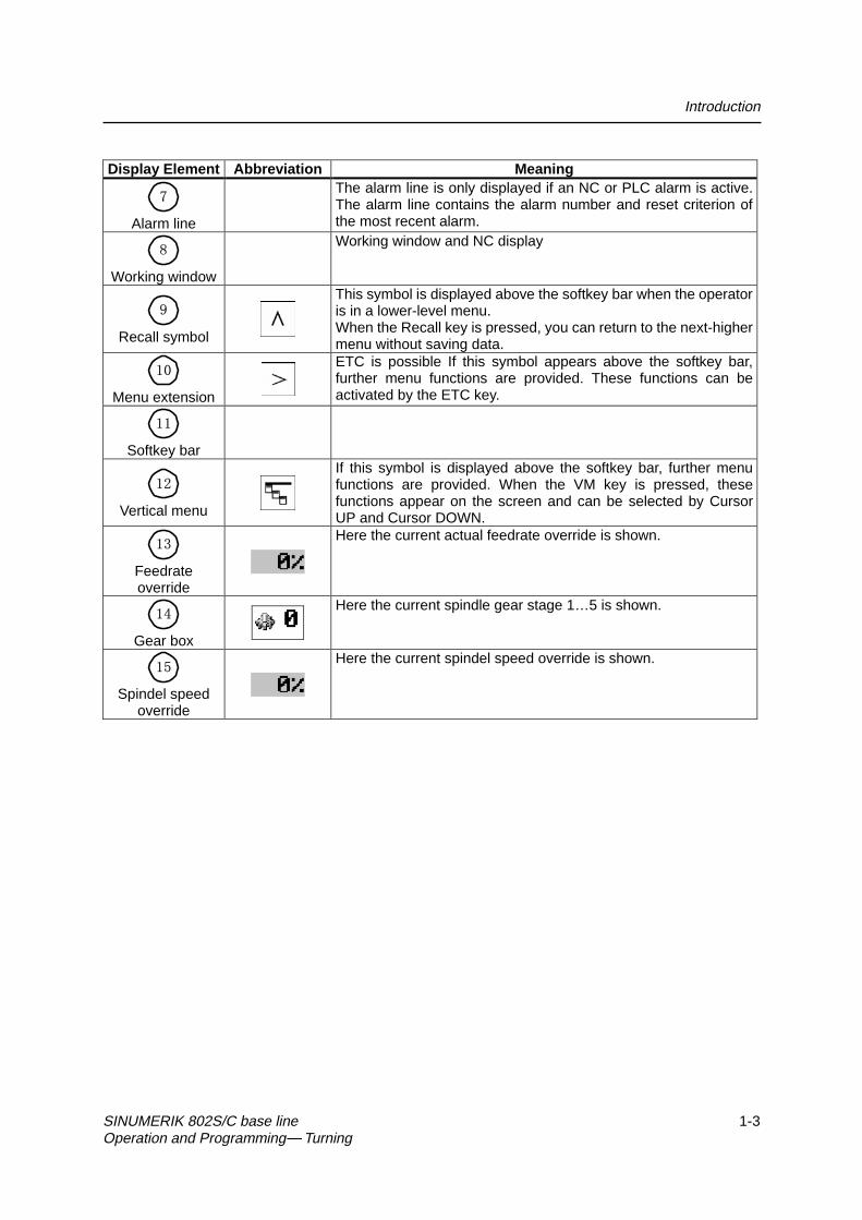
Display Element Abbreviation Meaning
�
Alarm line
The alarm line is only displayed if an NC or PLC alarm is active.The alarm line contains the alarm number and reset criterion ofthe most recent alarm.
�
Working window
Working window and NC display
�
Recall symbol
This symbol is displayed above the softkey bar when the operatoris in a lower-level menu.When the Recall key is pressed, you can return to the next-highermenu without saving data.
��
Menu extension
ETC is possible If this symbol appears above the softkey bar,further menu functions are provided. These functions can beactivated by the ETC key.
��
Softkey bar
��
Vertical menu
If this symbol is displayed above the softkey bar, further menufunctions are provided. When the VM key is pressed, thesefunctions appear on the screen and can be selected by CursorUP and Cursor DOWN.
��
Feedrateoverride
Here the current actual feedrate override is shown.
��
Gear box
Here the current spindle gear stage 1…5 is shown.
��
Spindel speedoverride
Here the current spindel speed override is shown.

Introduction
1-4 SINUMERIK 802S/C base line Operation and Programming Turning
1.2 Operating areas
The basic functions are grouped in the CNC into the following operating areas:
Machine Parameters Program Services Diagnostics
ExecutingpartprogramsManualcontrol
Editingprogramdata
Creatingpartprograms
Readingin / readingout data
AlarmdisplayStart-up
Operating areas
Fig.1-2 SINUMERIK 802S/C base line operating areas
Switching between the operating
Press the “Machine” area key for direct access to the “Machine” operatingarea.
Use the area switching key to return from any operating area to the mainmenu.
Press the area switching key twice to return to the previous operating area.
After turning on the control system, the Machine operating area will appear bydefault.
Protection levels Sensible points of the control system are password-protected against enteringand modifying data.
However, the operator can alter the protection levels in the “Machine Data”display menu in the “Diagnostics” operating area.
Default: Protection level 3.
In the following menus, entering and modifying data depends on the set classof protection:
z tool offsets
z zero offsets
z setting data
z RS232 settings
Introduction
SINUMERIK 802S/C base line 1-5Operation and Programming Turning
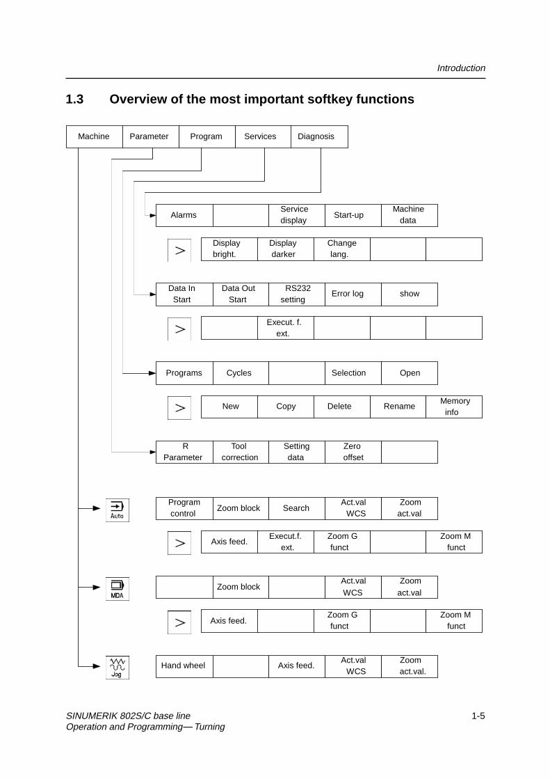
1.3 Overview of the most important softkey functions
Machine Parameter Program Services Diagnosis
AlarmsServicedisplay
Start-upMachine
data
Displaybright.
Displaydarker
Changelang.
Data InStart
Data OutStart
RS232setting
Error log show
Execut. f.ext.
Programs Cycles Selection Open
New Copy Delete RenameMemory
info
RParameter
Toolcorrection
Settingdata
Zerooffset
Programcontrol
Zoom block SearchAct.val
WCSZoom
act.val
Axis feed.Execut.f.
ext.Zoom Gfunct
Zoom Mfunct
Zoom blockAct.valWCS
Zoomact.val
Axis feed.Zoom Gfunct
Zoom Mfunct
Hand wheel Axis feed.Act.val
WCSZoomact.val.

Introduction
1-6 SINUMERIK 802S/C base line Operation and Programming Turning
1.4 Pocket calculator
This function can be activated for all input fields intended for entry of numericalvalues by means of the “=” character. To calculate the required value, you canuse the four basic arithmetic operations, and the functions sine, cosine,squaring, as well as the square root function.
If the input field is already loaded with a value, this function writes the value inthe input line of the pocket calculator.
Fig. 1-3 Pocket calculator
Permissible charactersThe following characters are permitted for input:
+ Value X plus value Y
- Value X minus value Y
* Value X multiplied with value Y
/ Value X divided by value Y
� 6 6LQH�IXQFWLRQ
� 7KH�YDOXH�;�LQ�IURQW�RI�WKH�LQSXW�FXUVRU�LV�UHSODFHG�E\�WKH�YDOXH
VLQ�;��
C Cosine function The value X in front of the input cursor is replaced by the value cos(X).
Q Square function The value X in front of the input cursor is replaced by the value X2.
R Square root function The value X in front of the input cursor is replaced by the value √X.
Calculation examples
Task Input100 + (67*3) 100+67*3sin(45°) 45 S -> 0.707107cos(45°) 45 C -> 0.70710742 4 Q -> 16√ 4 4 R -> 2
The calculation is carried out by pressing the Input key. The softkey function OKwill accept the result into the input field, quitting the calculator automatically.
To calculate auxiliary points on a contour, the calculator provides the followingfunctions:
z calculating the tangential transition between a circle sector and a straightline
z moving a point in a plane
z converting polar coordinates into Cartesian coordinates
z adding the second end point of a contour section ‘straight line - straightline’ given via angular interrelation.

Introduction
SINUMERIK 802S/C base line 1-7Operation and Programming Turning
These functions are directly linked with the input fields of the programmingsupport. Any values in this input field are written by the pocket calculator intothe input line, and the result is automatically copied into the input fields of theprogramming support.
Softkeys
This function is used to calculate a point on a circle. The point results from theangle of the created tangent and the direction of rotation of the circle.
Fig.1-4 Calculation of a point on a circle
Enter the circle center, the angle of the tangent and the radius of the circle.
The function switches the screen form from diameter programming to radiusprogramming.
Use softkey G2 / G3 to define the direction of rotation of the circle.
The abscissa and ordinate values are calculated; the abscissa is the first axisof the plane, and the ordinate is the second axis of the plane.
If plane G18 is active, the abscissa is the Z axis, and the ordinate is the X axis.
The value of the abscissa is copied into that input field from which the pocketcalculator function has been called, and the ordinate value into the nextfollowing input field.
Example Calculating the intersection point between the circle sector and the
straight line .
Given: Radius: 10Circle center point: Z 147 X103Ongoing angle of the straight line: -45°

Introduction
1-8 SINUMERIK 802S/C base line Operation and Programming Turning
Result: Z = 154.071X = 117.142
The function calculates the missing end point of the contour section straightline - straight line, with the second straight line standing vertically on the firststraight line.
The following values of the straight line are known:
Straight line 1: Start point and rise angle
Straight line 2: Length and one end point in the Cartesian coordinate system
Fig.1-5
The function switches the screenform from diameter programming to radiusprogramming.
The function chooses the given coordinate of the end point. The value ofordinate and/or abscissa is given.
The second straight line is rotated in clockwise direction or, with refer to thefirst straight line, rotated by 90 degrees in counter-clockwise direction.
The function chooses the appropriate setting.
The missing end point is calculated. The value of the abscissa is copied intothat input field from which the pocket calculator function has been called, andthe ordinate value into the next following input field.

Introduction
SINUMERIK 802S/C base line 1-9Operation and Programming Turning
Fig.1-6
The drawing above must be added by the value of the circle center point to beable to calculate the intersection point between the circle sector of the straightline. The missing coordinate of the center point is calculated by means of the
pocket calculator function , since the radius in the tangential transitionstands vertical on the straight line.
Calculating M1 in section 1:
In this section, the radius stands on the straight line section rotated in counter-clockwise direction.
Use the softkeys and to select the given constellation .
Enter the coordinates, the pole point P1, the rise angle of the straight line, thegiven ordinate value and the circle radius as the length.
Fig.1-7
Result: Z = 24.601X = 60

Introduction
1-10 SINUMERIK 802S/C base line Operation and Programming Turning
1.5 Coordinate systems
Right-handed, rectangular coordinate systems are used for machine tools.Such systems describe the movements on the machine as a relative motionbetween tool and workpiece.
Fig.1-8 Specification of the axis directions to one another; coordinate system
when programming for turning
Machine coordinate The orientation of the coordinate system on the machine depends on the particularsystem (MCS) machine type. It can be turned to various positions.
Fig. 1-9 Machine coordinates/axes on a turning machine
The origin of this coordinate system is the machine zero.
All axes are in the zero position at this point. This point is merely a referencepoint determined by the machine manufacturer. It does not need to beapproachable.
The traversing range of the machine axes can be negative.

Introduction
SINUMERIK 802S/C base line 1-11Operation and Programming Turning
Workpiece coord- The coordinate system described above (see Fig. 1–8) is also used to describeinate system (WCS) the geometry of a workpiece in the workpiece program.
The workpiece zero can be freely selected in the Z axis by the programmer. Inthe Z axis, the zero point corresponds to the turning center.
XW orkp iec e
ZW orkp iec e
W
W orkp iece
W- w orkpiece zero
Fig.1-10 Workpiece coordinate system
Workpiece clamping To machine the workpiece, it is clamped in the machine. The workpiece mustbe aligned such that the axes of the workpiece coordinate system are inparallel with the machine axes. Any resultant offset of the machine zero to theworkpiece zero is determined in the Z axis and entered in a specially provideddata area for the settable zero offset. This offset is activated during the NCprogram execution by means, for example, of a programmable G54 (seeSection “Workpiece Clamping - Settable Zero Offset ...”).
XM ac h in e XW orkp iec e
ZW orkp iec e
M W
z.B .
Z
G 5 4
W orkp iece
M ac h in e
Fig.1-11 Workpiece on the machine
Current workpiece An offset in relation to the workpiece coordinate system can be generated bycoordinate system means coordinate system of the programmable zero offset G158. The result is
the current workpiece (see Section “Programmable Zero Offset: G158”).

Introduction
1-12 SINUMERIK 802S/C base line Operation and Programming Turning

SINUMERIK 802S/C base line 2-1Operation and Programming Turning
Turning On and Reference Point 2Approach
Notice
Before you switch on the SINUMERIK and the machines, you should also haveread the machine documentation, since turning on and reference pointapproach are machine-dependent functions.
Operating sequence First switch on the power supply of the CNC and of the machine. After thecontrol system has booted, you are in the “Machine” operating area, in the Jogoperating mode.
The Reference point approach window is active.
Fig.2-1 Jog Ref basic screen
Reference-point approach can only be executed in the Jog mode.
Activate the “Approach reference point” function by selecting the Ref key onthe machine control panel area.
In the “Reference point approach” window (Fig. NO TAG), it is displayedwhether or not the axes have to be referenced.
Axis has to be referenced
Axis has reached the reference point

Turning On and Reference Point Approach
2-2 SINUMERIK 802S/C base line Operation and Programming Turning
… Press the direction keys.
The axis does not move if you select the wrong direction.
Approach the reference point in each axis successively.
You can quit the function by selecting another operating mode (MDA,Automatic or Jog).

SINUMERIK 802S/C base line 3-1Operation and Programming Turning
Set Up 3
Preliminary remarks Before you can use the CNC, set up the machine, tools, etc. on the CNC by:
z entering the tools and tool offsets
z entering/modifying the zero offset
z entering the setting data
3.1 Entering tools and tool offsets
Functionality The tool offsets consist of several data that describe the geometry, wear andtool type.
Each tool has a defined number of parameters depending on the tool type.
Each tool is identified by its own tool number (T number).
See also Section 8.6 “Tool and Tool Offset“.
Operating sequences This function opens the Tool Compensation Data window, which contains the
offset values of the currently active tool. If you select another tool using the <<Tor T>> softkeys, the setting remains when you quit the window.
Parameter
Fig.3-1 Tool compensation data window
ToolCorr.

Set Up
3-2 SINUMERIK 802S/C base line Operation and Programming Turning
GetComp.
Delete tool
<< T
T >>
<< D
D >>
New edge
Softkeys
Select next lower or next higher edge number.
Select next lower or next higher tool.
Determine length compensation values.
Use the ETC key to extend the softkey functions.
Resetedge All edge compensation values are reset to zero.
Creates a new edge and loads it with the appropriate parameters.
The new edge is created for the currently displayed tool; it is automaticallyassigned the next higher edge number (D1 – D9).
Max. 30 edges (in total) can be stored in the memory.
Deletes the tool compensation data of all edges of the selected tool.
Creates new tool compensation data for a new tool.Note: Max. 15 tools can be created.
Pressing this softkey opens the dialog box and the overview of the toolnumbers assigned. Enter the tool number you search for in the input windowand start search with OK. If the searched tool exists, the search function opensthe tool offset data box.
Newtool
Search

Set Up
SINUMERIK 802S/C base line 3-3Operation and Programming Turning
OK
3.1.1 Creating a new tool
Operating sequence
Press this softkey to create a new tool.
Pressing this softkey opens the input window and an overview of the toolnumbers assigned.
Fig 3-2 New Tool window
… Enter the new T number (maximal only three digits) and specify the tool type.
Press OK to confirm your entry; the Tool Compensation Data window isopened.
Newtool

Set Up
3-4 SINUMERIK 802S/C base line Operation and Programming Turning
3.1.2 Tool compensation data
The tool compensation data are divided into length and radius compensationdata.
The list is structured according to the tool type.
Fig.3-3 Tool compensation data window
Operating sequence Enter the offsets by
positioning the cursor on the input field to be modified,
… entering value(s)
and confirming your entry by pressing Input or a cursor selection.

Set Up
SINUMERIK 802S/C base line 3-5Operation and Programming Turning
3.1.3 Determining the tool offsets
Functionality This function can be used to determine the unknown geometry of a tool T.
Prerequisite The appropriate tool has been changed. In JOG mode, approach a point on themachine, from which you know the machine coordinates, with the edge of thetool.This can be a tool with a known position. The machine coordinate valuecan be split into two components: stored zero offset and offset.
Procedure Enter the offset value into the intended Offset field. Then select the requiredzero offset (e.g. G54) or G500 if no zero offset is to be calculated. Theseentries must be made for each selected axis (see Fig. 3-6).
Please note the following: The assignment of length 1 or 2 to the axisdepends on the type of tool (turning tool, drill)..For the turning tool, the offset value for the X axis is a diameter dimension.
Using the actual position of point F (machine coordinate), the offset entry andthe selected zero offset Gxx (position of the edge), the control system cancalculate the assigned compensation value of length 1 or length 2 for thepreselected axis.
Note : You can also use a zero offset already determined (e.g. G54 value) asthe known machine coordinate. In this case, approach to workpiece zero withthe edge of the tool. If the edge stands directly at the workpiece zero, the offsetvalue is zero.
XM ach in e
Z
W orkpiec e
M ach in e
F
Len gth 2= ?
Actu al p os it ion Zit i
F - too l c a rrie r re fe renc e poin t
Le
ng
th 1
=?
Actu al p os it ion X
O ffset
Off
se
tM
M - m ach ine zero
The o ffse t va lue o f the X axis is a d iam ete r va lue .
W
W - w orkp iec e zero
G xx
Fig.3-4 Determination of the length compensation values using the example ofa cutting tool

Set Up
3-6 SINUMERIK 802S/C base line Operation and Programming Turning
XM ac h in e
M
Z
W orkp iece
M ac h in e
L en g th 1= ?
A c tu a l p os it ion Z
F - w o rk p iec e re fe re n c e p o in t
M -m ac h in e ze ro
FW
O ffs etG xx
W -w o rk pie ce ze ro
Fig.3-5 Determination of length compensation value using the example of adrill: Length 1/Z axis
Operating sequence
Select the softkey Get Comp. The window Compensation values opens.
Fig.3-6 Compensation values window
z Enter offset if the tool edge cannot approach the zero point Gxx. If youwork without zero offset, select G500 and enter offset.
z When the softkey Calculate is pressed, the control system determines thesearched geometry length 1 or 2 depending on the preselected axis. Thisgeometry is calculated on the basis of the approached actual position, theselected Gxx function and the entered offset value.
The determined compensation value is stored.
GetComp.
Set Up
SINUMERIK 802S/C base line 3-7Operation and Programming Turning
3.2 Entering/modifying the zero offset
Functionality The actual-value memory and thus also the actual-value display are referred tothe machine zero after the reference-point approach. The workpiece machiningprogram, however, refers to the workpiece zero.This offset must be entered as the zero offset.
Operating sequences
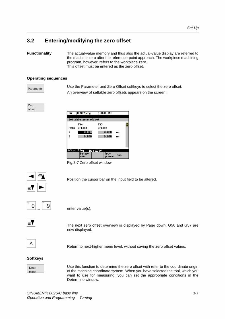
Use the Parameter and Zero Offset softkeys to select the zero offset.
An overview of settable zero offsets appears on the screen .
Fig.3-7 Zero offset window
Position the cursor bar on the input field to be altered,
… enter value(s).
The next zero offset overview is displayed by Page down. G56 and G57 arenow displayed.
Return to next-higher menu level, without saving the zero offset values.
Softkeys
Use this function to determine the zero offset with refer to the coordinate originof the machine coordinate system. When you have selected the tool, which youwant to use for measuring, you can set the appropriate conditions in theDetermine window.
Deter-mine
Parameter
Zerooffset

Set Up
3-8 SINUMERIK 802S/C base line Operation and Programming Turning
A window with the programmed zero offset is displayed. The values in thewindow cannot be edited.
Displays the sum of all active zero offsets. The values cannot be edited.
3.2.1 Determining the zero offset
Prerequisite You have selected the window with the corresponding zero offset (e.g. G54)and the axis for which you want to determine the offset.
X Machine
M
Z
Workpiece
Machine
Zero offset Z=?
F
Length 2
Actual Z position
F - tool support reference point
M - machine zero
W
W - workpiece zero
Fig.3-8 Determining the zero offset for the Z axis
Approachz A zero offset can only be determined with a known tool. Enter the active
tool in the dialog box. Press OK to take over the tool; the Determinewindow is then opened.
z The selected axis appears in the Axis area.
The actual position of the tool support reference point (MCS) associatedto the axis is displayed in the adjacent field.
z D number 1 is displayed for the tool edge.
If you have entered the valid offsets for the used tool under a D numberother than D1, enter that D number here.
z The stored tool type is displayed automatically.
z The effective length compensation value (geometry) is displayed.
z Select the sign (-, +) for calculating the length offset, or select “without”taking the length offset into account.
A negative sign subtracts the length offset value from the actual position.The zero offset in the selected axis is the result.
z Offset
If the tool does not reach zero, an offset can be entered to specify anadditional offset to a point which can be approched by the tool.
Pro-grammed
Sum

Set Up
SINUMERIK 802S/C base line 3-9Operation and Programming Turning
Fig.3-9 Select Tool screen form
Fig.3-10 Determine zero offset form
Softkey can be used to select the zero offsets G54 to G57. The selected zerooffset is displayed on the selected softkey.
Selects the next axis.
Pressing the Calculate softkey calculates the zero offset.
Press the OK softkey to quit the window.
NextUFrame
NextAxis
Calcu-late
OK

Set Up
3-10 SINUMERIK 802S/C base line Operation and Programming Turning
3.3 Programming the setting data - “Parameters” operating area
Functionality Use the setting data to define the settings for the operating states. These canalso be modified if necessary.
Operating sequences
Use the Parameter and Setting Data softkeys to select Setting Data.
The Setting Data softkey branches to another menu level in which variouscontrol options can be set.
Fig.3-11 Setting data main screen
Use the paging keys to position the cursor on the desired line within the displayareas.
… Enter the new value in the input fields.
Use Input or the cursor keys to confirm.
Softkeys
This function can be used to change the following settings:
Jog feed
Feed value in Jog mode
If the feed value is zero, the control system uses the value stored in themachine data.
Spindle
Spindle speed
Direction of rotation of the spindle
Jogdata
Parameter
Sett.data

Set Up
SINUMERIK 802S/C base line 3-11Operation and Programming Turning
Minimum / Maximum
Limits for the spindle speed set in the Max. (G26)/Min. (G25) fields must bewithin the limit values specified in the machine data.
Programmed (LIMS)
Programmable upper speed limitation (LIMS) at constant cutting speed (G96).
Dry-run feedrate for dry-run operation (DRY)
The feedrate you enter here is used in the program execution instead of theprogrammed feed during the Automatic mode when the Dry-Run Feedrate isactive (see Program Control, Fig. 5–3).
Start angle for thread cutting (SF)
A start angle representing the starting position for the spindle is displayed forthread cutting operations. It is possible to cut a multiple thread by altering theangle and repeating the thread cutting operation.
Spindledata
Dryfeed
Startangle

Set Up
3-12 SINUMERIK 802S/C base line Operation and Programming Turning
3.4 R parameters – “Parameters” operating area
Functionality All R parameters (arithmetic parameters) that exist in the control system aredisplayed on the R Parameters main screen as a list (see also Section 8.8“Arithmetic Parameters /R Parameters”). These can be modified if necessary.
Fig.3-12 R Parameters window
Operating sequence
Use the Parameter and R Parameter softkeys
to position the cursor on the input field that you want to edit.
… Enter value(s).
Press Input or use the cursor keys to confirm.
Parameters
R Para-meters

SINUMERIK 802S/C base line 4-1Operation and Programming Turning
Manually Operated Mode 4
Preliminary remarks
The manually operated mode is possible in the Jog and MDA mode.
In the Jog mode, you can traverse the axes, and in the MDA mode, you canenter and execute individual part program blocks.
4.1 Jog mode – “Machine” operating area
Functionality In Jog mode, you can
z traverse the axes and
z set the traversing speed by means of the override switch, etc.
Operating sequences
Use the Jog key on the machine control panel area to select the Jog mode.
… Press the appropriate key for the X or Z axis to traverse the desired axis.
As long as the direction key is pressed and hold down, the axes traversecontinuously at the speed stored in the setting data. If this setting is zero, thevalue stored in the machine data is used.
… If necessary use the override button key to set the traversing speed.
It can be adjusted by settable increments:
0%, 1%, 2%, 4%, 8%, 10%, 20%, 30%, 40%, 50%, 60%, 75%, 80%, 85%, 90%,95%, 100%, 105%, 110%, 115%, 120%.
If you press the Rapid Traverse Overlay key at the same time, the selectedaxis is traversed at rapid traverse speed as long as both keys are presseddown.

Manually Operated Mode
4-2 SINUMERIK 802S/C base line Operation and Programming Turning
In the Incremental Feed operating mode, you can use the same operatingsequence to traverse the axis by settable increments. The set increment isdisplayed in the display area. Jog must be pressed again to cancel theIncremental Feed.
The Jog main screen displays position, feed and spindle values, including thefeedrate override and spindle override, gear stage status as well as the currenttool.
Fig.4-1 Jog main screen
Parameters Table 4–1 Description of parameters in the Jog main screen
Parameter ExplanationMCSXZ
Display of addresses of existing axes in machinecoordinate system (MCS).
+X– Z If you traverse an axis in the positive (+) or negative (–)direction, a plus or minus sign appears in the respectivefield.No axis is displayed, if the axis is in position.
Act.mm
The current position of the axes in the MCS or WCS isdisplayed in these fields.
Reposoffset
If the axes are traversed in the Jog mode in the ProgramInterrupted condition, the distance traversed by each axisin relation to the break point is displayed in this column.
Spindle Srpm
Display of actual value and setpoint of spindle speed
Feed F mm/min Display of path feed actual value and setpointTool Display of currently active tool with the current cutting
edge numberActual feedrateoverride
Display of current feedrate override
Actual spindleoverride
Display of current spindlel speed override
Gear stage Display of current gear stage in the machine
Softkeys
Call the Handwheel window.Hand-wheel

Manually Operated Mode
SINUMERIK 802S/C base line 4-3Operation and Programming Turning
Call the Axis Feed or Interp. Feed window.
Use this softkey to change between the Axis Feed window and the Interp. Feedwindow.
The softkey label changes to Interp. feed when the Axis/Feed window isopened.
The actual values are displayed as a function of the selected coordinatesystem. There are two different coordinate systems, i.e. the machinecoordinate system (MCS) and the workpiece coordinate system (WCS).
The softkey changes between MCS and WCS. When doing this, the softkeylabel changes as follows:
z The values of the machine coordinate system are selected, the softkeylabel changes to Act. val. WCS.
z When the workpiece coordinate system is selected, the label changes toAct. val. MCS.
Enlarged view of actual values.
Pressing Recall key , return to the next-higher menu level.
Axisfeed
Interp./feed
Act. val.WCS
Act.val.MCS
Zoomact.val.

Manually Operated Mode
4-4 SINUMERIK 802S/C base line Operation and Programming Turning
4.1.1 Assigning handwheels
An axis is assigned to the respective handwheel and becomes active as soonas you press OK.
Operating Sequence
In Jog mode, call the Handwheel window.
After the window has opened, all axis identifiers are displayed in the Axiscolumn and also appear in the softkey bar. Depending on the number ofconnected handwheels, it is possible to change from handwheel 1 tohandwheel 2 using the cursor.
Place the cursor on the line with the handwheel to which you wish to assign anaxis. Then select the softkey that contains the name of the axis.
The symbol appears in the window.
Fig.4-2 Handwheel window
The WCS/MCS softkey is used to select the axes from the machine orworkpiece coordinate system for assignment to the handwheel. The currentsetting is displayed in the handwheel window.
Use the OK softkey to take over the selected setting; the window is thenclosed.
Menu extension
The assignment you have made is reset for the selected handwheel.
Hand–wheel
WCS
MCS
OK
De-select

Manually Operated Mode
SINUMERIK 802S/C base line 4-5Operation and Programming Turning
4.2 MDA mode (Manual Data Input) – “Machine” operating area
Functionality You can create and execute a part program block in the MDA mode.
Contours that require several blocks (e.g. roundings, chamfers) cannot beexecuted/programmed.
Caution
This mode is protected by the same safety interlocks as fully automatic mode.
Furthermore, the MDA mode is subject to the same prerequisites as the fullyautomatic mode.
Before NC-start of an input NC-program in the mode MDA is to wait till themessage “Block store active” displays on the screen.
Operating sequences
Use the MDA key in the machine control panel area to select the MDA mode.
Fig.4-3 MDA main screen
… Enter a block using the control keyboard.
The entered block is executed by pressing NC START. The block cannot beexecuted while machining is taking place.
!

Manually Operated Mode
4-6 SINUMERIK 802S/C base line Operation and Programming Turning
Parameters Table 4–2 Description of the parameters in the MDA working window.
Parameter ExplanationMCSXZ
Display of existing axes in MCS or WCS
+X– Z
If you traverse an axis in the positive (+) or negative (–)direction, a plus or minus sign appears in the respectivefield.No sign is displayed if the axis is in position.
Act. valuemm
The current position of the axes in the MCS or WCS isdisplayed in these fields.
Spindle Srpm
Display of actual value and setpoint of spindle speed
Feed F Display of path feed actual value and setpoint inmm/min or mm/rev.
Tool Display of currently active tool with the current tool edgenumber (T..., D...).
Edit window In the Stop or Reset program state, an edit window isprovided for input of the part program block.
Actual feedrateoverride
Display of current feedrate override
Actual spindleoverride
Display of current spindlel speed override
Gear stage Display of current gear stage in the machine
Softkeys
The actual values for the MDA mode are displayed as a function of theselected coordinate system.
There are two different coordinate systems, i.e. the machine coordinate system(MCS) and the workpiece coordinate system (WCS).
Enlarged view of the actual values
Menu extension
Display of Axis Feed or Interp. Feed window
this softkey can be used to change between the two windows. The softkeylabel changes to Interp. Feed when the Axis Feed window is opened.
The G function window contains all active G functions whereby each G functionis assigned a group and has its own fixed positon in the window.
Further G functions can be displayed using the Page Up or Page Down keystogether with Shift key. Select Recall to quit the window.
Act.val.WCS
Act.val.MCS
Zoomact.val.
Axisfeed
Interp.feed
ZoomG funct.

Manually Operated Mode
SINUMERIK 802S/C base line 4-7Operation and Programming Turning
The window shows the currently edited block full length.
Opens the M function window to display all active M functions of the block.
Zoomblock
ZoomM funct.
Manually Operated Mode
4-8 SINUMERIK 802S/C base line Operation and Programming Turning

SINUMERIK 802S/C base line 5-1Operation and Programming Turning
Automatic Mode 5
Functionality In Automatic mode, part programs can be executed fully automatically, i.e. thisis the operating mode for standard processing of part programs.
Preconditions The preconditions for executing part programs are:
z Reference point approached.
z You have already stored the required part program in the control system.
z You have checked or entered the necessary offset values, e.g. zerooffsets or tool offsets.
z The required safety interlocks are activated.
Operating sequence
Use the Automatic key to select the Automatic mode.
The Automatic main screen appears that displays the position, feed, spindle,override and tool values, the gear stage status as well as the current block.
Fig.5-1 Automatic main screen

Automatic Mode
5-2 SINUMERIK 802S/C base line Operation and Programming Turning
Parameters Table 5–1 Description of the parameters in the working window
Parameter ExplanationMCSXZ
Display of existing axes in MCS or WCS.
+ X– Z
If you traverse an axis in the positive (+) or negative (–)direction, a plus or minus sign appears in the respective field.No sign is displayed if the axis is in position.
Act. val.mm
The current position of the axes in the MCS or WCS is displayedin these fields.
Distanceto go
The remaining distance to be traversed by these axes in theMCS or WCS is displayed in these fields.
Spindle Srpm
Display of actual value and setpoint of spindle speed
Feed Fmm/min ormm/rev
Display of path feed actual value and setpoint
Tool Display of currently active tool with the current cutting edgenumber (T..., D...).
Currentblock
The block display contains the current block. The block is outputin one line only and truncated if necessary.
Actualfeedrateoverride
Display of current feedrate override
Actualspindleoverride
Display of current spindlel speed override
Gear stage Display of current gear stage in the machine
Softkeys
The window to select Program Control (e.g. skip block, program test) appearson the screen.
The window shows the previous, current and next block full length. In addition,the names of the current program or subroutine are displayed.
Use the Block Search function to jump to the desired point in the program.
The Search softkey provides the functions “Find line” and “Find text”.
The cursor is positioned to the main program block of the breakpoint (”interruptpoint”). The search target is automatically set in the subroutine levels.
Continue Search
Progr.control
Zoomblock
Search
Search
Interr.point
Contin.search

Automatic Mode
SINUMERIK 802S/C base line 5-3Operation and Programming Turning
The Start B Search softkey starts the search process in which the samecalculations are carried out as in normal program mode, but without axismovements.
The block search can be canceled by NC Reset.
The values of the machine or workpiece coordinate system are selected. Thesoftkey label changes to Act. val. WCS or Act. val. MCS.
Enlarged view of actual values
Menu extension
When pressing these softkeys, the Axis Feed or Interp. Feed window appears.
This softkey can be used to change between the windows. The softkey labelchanges to Interp. feed when the Axis Feed window is opened.
An external program is transferred into the control system via the RS232interface and executed immediately by pressing NC START.
Opens the G Function window to display all active G functions.
The G Function window contains all active G functions. Each G function isassigned to a group and has a fixed position in the window. More G functionscan be displayed by pressing the PAGE UP or PAGE DOWN keys togetherwith Shift key.
DEMO
Fig.5-2 Active G functions window
Opens the M Function window to display all active M functions.
Start Bsearch
Act.val.WCS
Act.val.MCS
Zoomact.val.
Axisfeed
Interp.feed
Executef. ext.
ZoomG Funkt.
ZoomM funct.

Automatic Mode
5-4 SINUMERIK 802S/C base line Operation and Programming Turning
5.1 Selecting/starting a part program – “Machine” operating area
Functionality The control system and the machine must be set up before the program isstarted. Please note the safety instructions provided by the machinemanufacturer.
Operating sequence
Use the Automatic key to select the Automatic mode.
An overview of all programs stored in the control system is displayed.
Position the cursor bar on the desired program.
Use the Select softkey to select the program for execution. The selectedprogram name appears in the Program Name screen line.
If necessary you can now make settings on program execution.
The following program control functions can be activated and deactivated:
Fig.5-3 Program control window
The part program is executed when NC START is pressed.
Select
Progr.control
Programs

Automatic Mode
SINUMERIK 802S/C base line 5-5Operation and Programming Turning
5.2 Block search – “Machine” operating area
Operating sequence Precondition: The desired program has already been selected (cf. Section 5.1),and the control system is in the reset state.
The block search function can be used to advance the program up to thedesired point in the part program. The search target is set by positioning thecursor directly on the desired block in the part program.
DEMO.M
Fig.5-4 Block search window
This function starts program advance and closes the Search window.
Result of the search The desired block is displayed in the Current Block window.
Search
Start Bsearch

Automatic Mode
5-6 SINUMERIK 802S/C base line Operation and Programming Turning
5.3 Stopping/aborting a part program – “Machine” operating area
Functionality Part programs can be stopped and aborted.
Operating Sequence
The execution of a part program can be interrupted by selecting NC STOP.The interrupted program can be continued by NC START.
The current program can be aborted by pressing RESET.When you press NC START again, the aborted program is restarted andexecuted from the beginning.

Automatic Mode
SINUMERIK 802S/C base line 5-7Operation and Programming Turning
5.4 Repositioning after interruption – “Machine” operating area
Functionality After a program interruption (NC STOP), you can move the tool away from thecontour in the manual mode (Jog). The control system stores the coordinatesof the breakpoint (”interrupt point”). The path differences traversed by the axesare displayed.
Operating sequence
Select the Automatic mode.
Open the Block Search window to load the breakpoint.
The breakpoint is loaded. The routine is adjusted to the start position of theinterrupted block.
A block search to the breakpoint is started.
Continue execution of the program by NC START.
Search
Interr.Point
Start Bsearch

Automatic Mode
5-8 SINUMERIK 802S/C base line Operation and Programming Turning
5.5 Program execution from external (RS232 interface)
Functionality An external program is transferred to the control system via the RS232interface and executed immediately by pressing NC START.
While processing the contents of the buffer memory, the program isautomatically reloaded. For example, as an external device, a PC can be used,on which the WinPCIN tool for data transfer is installed.
Operating sequence Prerequisite: The control system is reset.
The RS232 interface is parameterized correctly (see Chapter 7) and notoccupied by any other application (DataIn, DatatOut, STEP7).
Press this softkey.
Use WinPCIN (or PCIN) on the external device (PC) to set the program fordata output active.
The program is transferred to the buffer memory and automatically selectedand displayed in the program selection.
For the program execution, it is advantageous to wait until the buffer memory isfilled.
The program execution starts with NC START. The program is reloadedcontinuously.
Either at the end of the program or when pressing RESET, the program isautomatically removed from the control system.
Note
z As an alternative, External Program Execution can also be activated inthe Services area.
z Any transfer errors are displayed in the Services area when you press theError log softkey.
Executef. ext.

Automatic Mode
SINUMERIK 802S/C base line 5-9Operation and Programming Turning
5.6 Teach-in
Functionality Use the submode Teach In to accept the axis position values directly into aparts program block to be generated or modified.
The axis positions are approached either in Automatic mode by traversing theJOG keys or by using the handwheel. However, first press the appropriatesoftkey (see below) in the Programming operating area to enable the submodeTeach In.
Operating sequence Prerequisite:
� Teach-in option is set (display MD 278=4)
� The control system is either in the state Stop or Reset.
A list of all programs existing in the control system is displayed.
Pressing Open calls the editor for the selected program and opens the editorwindow.
Menu extension
Select
Menu extension
Select
Fig.5-5 Teach in main screen
Softkeys
Use this softkey to generate a block with technological data.
Programs
open
Edit
Teach Inon
Technol. Data

Automatic Mode
5-10 SINUMERIK 802S/C base line Operation and Programming Turning
Use this screen form to enter
z feed value
z spindle speed and direction of rotation
z tool and edge number
z Feed mode (active; mm/min corresponds to G64; mm/rev. of spindlecorresponds to G96)
z Positioning behavior (active; exact stop G60; continuous-path controlmode G64)
Fig.5-6 Input screen form for technological data
When you press OK, a block with the technological data entered is generatedand inserted in front of the block to which the cursor is positioned. PressingRECALL cancels your entry and lets you return to the Teach In main screen.
Use this softkey to generate NC blocks using the traversing keys or thehandwheel.
Simple NC blocks are generated by traversing with parallel axes using eitherthe traversing keys of the axes or the handwheel. It is also possible to correctthe values of an existing blocks.
Fig.5-7 Teach in of NC blocks
Use this softkey to generate a rapid traverse block (G0).
Use this softkey to generate a linear feed block (G1).
Use this softkey to generate a circular block (G5 with intermediate point andend point).
Teach InRecords
FastTrav.
Linear
Circul.

Automatic Mode
SINUMERIK 802S/C base line 5-11Operation and Programming Turning
Use this softkey to generate a block with the values taught. The new block isinserted in front of the block to which the cursor is positioned.
Values are corrected in the block (accepted from the screen form) to which thecursor is positioned.
Use RECALL to return to the Teach In main screen. Any amendments you wishto make can be later inserted manually.
Use this softkey to generate an M2 block to be inserted after the current block(cursor position).
Use this softkey to traverse the programmed block.
The machine screen set in Automatic mode appears again. Use NC Start tocontinue the selected but interrupted program from the block selected last (ifthe control system has not been in Reset state). Teach In remains enabled.Block search with Teach In active is not possible.
Use this softkey to turn off the submode Teach In.
Note
After turning off Teach In, the interrupted program can no longer be edited.
Example Teaching a G5 block
Fig.5-8 Teach in of a circular block
z The program block with G5 is selected by the cursor.
z Press the softkey Circul.
The circle start point is the end point of the previous block.
z Approach to the intermediate point of the contour and press AcceptChange.
z Approach to the end point of the contour and press Accept Change.
AcceptInsert
AcceptChange
FinishRecord
Progr.run
TeachIn Off

Automatic Mode
5-12 SINUMERIK 802S/C base line Operation and Programming Turning

SINUMERIK 802S/C base line 6-1Operation and Programming Turning
Part Programming 6Functionality This Section describes how to create a new part program.
The standard cycles can also be displayed provided you have the requiredaccess authorization.
Operating sequence
You are in the main menu.
The Programming main screen appears.
Fig.6-1 Programming main screen
When the Program operating area is selected for the first time, the directory forpart programs and subroutines is automatically selected (see above).
Softkeys
The Standard Cycles directory is displayed by pressing the Cycles softkey.
This softkey is only displayed if the operator has the appropriate accessauthorization.
This function selects the program highlighted by the cursor for execution. Theprogram is started on next NC START.
Opens the files selected by the cursor for editing.
Menu extension
Pro-grams
Cycles
Open
Select
Part Programming
6-2 SINUMERIK 802S/C base line Operation and Programming Turning
Use the New softkey to create a new program. A window appears in which youare prompted to enter program name and type.
After you have confirmed your inputs by OK, the program editor is called, andyou can enter part program blocks. Select RECALL to cancel this function.
Use the Copy softkey to copy the selected program into another program.
The program highlighted by the cursor is deleted after the system hasrequested confirmation of the delete operation.
Press OK to confirm the Delete request and RECALL to cancel it.
When you select the Rename softkey, a window appears in which you canrename the program that you have already highlighted by the cursor.
After you have entered the new name, confirm your rename request by OK orcancel by RECALL.
The Programs softkey can be used to change to the program directory.
When you press this softkey, the totally available NC memory (in kbytes) isdisplayed.
Copy
Delete
MemoryInfo
New
Rename

Part Programming
SINUMERIK 802S/C base line 6-3Operation and Programming Turning
6.1 Entering a new program – “Program” operating area
Functionality This Section describes how to create a new file for a part program. A windowappears in which you are prompted to enter program name and type.
DEMO.
Fig.6-2 New program input screen form
Operating sequences
You have selected the Program operating area. The Program Overviewwindow showing the programs already stored in the CNC is displayed on thescreen.
Press the New softkey. A dialog window appears in which you enter the newmain program or subroutine program name. The extension .MPF for mainprograms is automatically entered. The extension .SPF for subroutines mustbe entered with the program name.
… Enter the new name.
Complete your input by selecting the OK softkey. The new part program file isgenerated and is now ready for editing.
The creation of the program can be interrupted by RECALL; the window is thenclosed.
Program
New
OK

Part Programming
6-4 SINUMERIK 802S/C base line Operation and Programming Turning
6.2 Editing a part program – “Program” operating area
Functionality Part programs or sections of a part program can only be edited if not beingexecuted.
DEMO.MPF
Fig. 6-3 Editor window
Operating sequence
You are in the main menu and have selected the Programs operating area. Theprogram overview appears automatically.
Use the paging keys to select the program you wish to edit.
Pressing the open softkey calls the editor for the selected program and pullsdown the editor window.
The file can now be edited. All changes are stored immediately.
Softkeys
User-assignable softkeys
You can assign predefined functions to the softkeys 1 - 4 (see Section 6.3.4“User-Assignable Softkeys”).
The softkeys are assigned process-specific functions by the controlmanufacturer.
The contour functions are described in Section 6.3 ”Programming Support”.
Menu extension
This function selectes section of text up to the current cursor position.
Contour
Edit
Mark
Programs
open

Part Programming
SINUMERIK 802S/C base line 6-5Operation and Programming Turning
This function deletes the selected text.
This function copies selected text to the clipboard.
This function inserts text from the clipboard at the current cursor poisition.
For re-compilation, the cursor must stand on the cycle call line in the program.The required parameters must be arranged directly in front of the cycle call andmay not be separated by instruction or comment lines. The function decodesthe cycle name and prepares the screen form with the respective parameters.If there are any parameters are outside the validity range, the functionautomatically uses standard values. When the screen form has been quitted,the original parameter block is automatically replaced by the corrected one.
Note: Only automatically generated blocks can be recompiled.
Note
To carry out these functions outside the Edit menu, it is also possible to use thekey combinations <SHIFT> and
softkey 1 Selectsoftkey 2 Delete blocksoftkey 3 Copy blocksoftkey 4 Insert block.
Menu extension
This function can be used to change the assignment of the softkey functions 1 -4.
For more detail description refer to Section NO TAG.
The softkeys Search and Contin. search can be used to search for a stringchain in the program file displayed on the screen.
Type the text you wish to find in the input line and start the Search operation byselecting the OK softkey.
If the character string you have specified cannot be found in the program file,an error message appears that must be acknowledged with OK.
You can exit the dialog box without starting the search by selecting RECALL.
Type the line number in the input line.
The search is started by pressing OK.
You can quit the dialog box without starting the search by selecting RECALL.
The functions searches through the file to find another character string thatmatches the target string.
Delete
Copy
Past
Recomp.cycles
AssignSK
Search
Text
Line no.
Contin.Search

Part Programming
6-6 SINUMERIK 802S/C base line Operation and Programming Turning
This function stores the changes in the file system and automatically closes thefile.
Editing cyrillic letters
This function is only avaiable if the Russian language option is selected.
Procedure The control system offers a window for cyrillic letters to choose from. This isenabled/disabled using the Toggle key.
Fig.6-4
To select a character,
z use the letters X, Y or Z to choose the line
z and then enter the digit or the letter assigned to the correspondingcolumn.
When you enter the digit, the character will be copied into the edited file.
Close

Part Programming
SINUMERIK 802S/C base line 6-7Operation and Programming Turning
6.3 Programming support
Functionality The programming support facility contains various help levels simplifying theprogramming of part programs without constraining your choice of inputs.
6.3.1 Vertical menu
Functionality The vertical menu is displayed in the program editor.
The vertical menu allows you to quickly insert certain NC instructions into thepart program.
Operating sequence You are in the program editor.
Press the VM key and select the desired instruction from the list.
Fig.6-5 Vertical menu
Lines that end in “...” contain a collection of NC instructions. You can list theseinstructions by pressing the Input key or entering the number of the line.
Fig.6-6 Vertical menu
Use the paging keys to browse through the list.
Part Programming
6-8 SINUMERIK 802S/C base line Operation and Programming Turning
Confirm your entry by pressing Input .
Alternatively, the number of the lines from 1 to 7 can be entered to selectinstructions and take them over into the part program.
6.3.2 Cycles
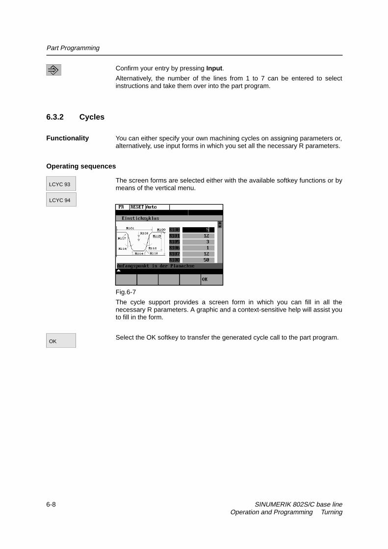
Functionality You can either specify your own machining cycles on assigning parameters or,alternatively, use input forms in which you set all the necessary R parameters.
Operating sequences
The screen forms are selected either with the available softkey functions or bymeans of the vertical menu.
Fig.6-7
The cycle support provides a screen form in which you can fill in all thenecessary R parameters. A graphic and a context-sensitive help will assist youto fill in the form.
Select the OK softkey to transfer the generated cycle call to the part program.
LCYC 93
LCYC 94
OK

Part Programming
SINUMERIK 802S/C base line 6-9Operation and Programming Turning
6.3.3 Contour
Functionality The control system provides you with various contour forms to assist you increating part programs quickly and reliably. Enter the necessary parameters inthe screen forms and confirm your inputs.
The contour screen forms can be used to program the following contourelements and contour sections:
z Straight section with specification of end point or angle
z Circle sector with specification of center point / end point
z Circle sector with specification of center point / opening angle
z Circle sector with specification of center point / radius
z Straight line/straight line contour section with specification of angle andend point
z Straight line/circle contour section with tangential transition; calculatedfrom angle, redius and end point
z Straight line/circle contour section with any transition; calculated fromangle, center point and end point
z Circle/straight line contour section with tangential transition; calculatedfrom angle, radius and end point
z Circle/straight line contour section with any transition; calculated fromangle, center point and end point.
z Circle/circle contour section with tangential transition; calculated fromcenter point, radius and end point
z Circle/circle contour section with any transition; calculated from centerpoint and end positon
z Circle - straight line - circle contour section with tangential transitions
z Circle - circle - circle contour section with tangential transitions
Fig.6-8
Softkeys
The sofkey functions branch to the contour elements.
Programming aid for programming straight line sections.
Part Programming
6-10 SINUMERIK 802S/C base line Operation and Programming Turning
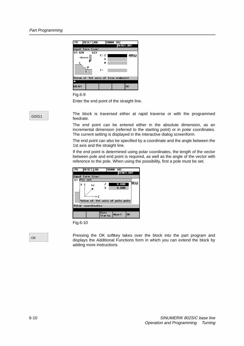
Fig.6-9
Enter the end point of the straight line.
The block is traversed either at rapid traverse or with the programmedfeedrate.
The end point can be entered either in the absolute dimension, as anincremental dimension (referred to the starting point) or in polar coordinates.The current setting is displayed in the interactive dialog screenform.
The end point can also be specified by a coordinate and the angle between the1st axis and the straight line.
If the end point is determined using polar coordinates, the length of the vectorbetween pole and end point is required, as well as the angle of the vector withreference to the pole. When using the possibility, first a pole must be set.
Fig.6-10
Pressing the OK softkey takes over the block into the part program anddisplays the Additional Functions form in which you can extend the block byadding more instructions.
G0/G1
OK

Part Programming
SINUMERIK 802S/C base line 6-11Operation and Programming Turning
Additional functions
Fig.6-11 Additional functions screen form
Enter additional commands in the fields. The commands can be separated bymeans of blanks, commas or semi-colons.
This screen form is available for all contour elements.
The OK softkey transfers the commands to the part program.
Select RECALL if you wish to exit the interactive form without saving thevalues.
The dialog screen form is used to create a circular block by means of the endand center point coordinates.
Fig.6-12
Enter the center point coordinates in the input fields.
To enter the coordinates, there are three variants:
z absolute
z incremental
z polar
This softkey changes the direction of rotation from G2 to G3. G3 appears onthe display.
When you press the softkey again, you will return to G2.
Pressing the OK softkey will accept the block into the part program and willoffer additional commands in another interactive screenform.
OK
G2/G3
OK

Part Programming
6-12 SINUMERIK 802S/C base line Operation and Programming Turning
This function is intended to calculate the intersection point between twostraight lines.
Specify the coordinates of the end point of the second straight line and theangles of the straight line. For the coordinate value, the toggle key can beused to choose between absolute, incremental or polar coorinates.
If the starting point cannot be selected based on the previous blocks, theoperator must set the starting point.
Fig. 6-13 Calculating the intersection point between two straight lines
Table 6–1 Input in the interactive screenform
End point ofstraight line 2
E Specify the end point of the straight line.
Angle ofstraight line 1
A1 The angle must be specified in the CCW direction inthe range between 0 and 360 degrees.
Angle ofstraight line 2
A2 The angle must be specified in the CCW direction inthe range between 0 and 360 degrees.
Feedrate F Feedrate
This function is used to calculate the tangential transition between a straightline and a circle sector. The straight line must be described by starting pointand angle. The circle must be described by the radius and by the end point.
To calculate intersection points with any transition angles, the POI softkeyfunction will display the center point coordinates.
Fig. 6–14Straight line - circle with tangential transition

Part Programming
SINUMERIK 802S/C base line 6-13Operation and Programming Turning
Table 6–2 Input in the interactive screenform
Circle endpoint
E The end point of the circle must be specified.
Straight lineangle
A The angle is specified in the CCW direction in therange between 0 and 360 degrees.
Circle radius R Input field for the circle radiusFeed F Input field for the interpolation feed.Circle centerpoint
M If there is no tangential transition between the straightline and the circle, the circle center must be known.The circle center point is specified depending on thecalculation method (absolute or incremental dimension/ polar coordinates) selected in the previous block.
This softkey is used to switch the direction of rotation from G2 to G3. G3 isdisplayed on the screen. Pressing this softkey once more will switch thedisplay back to G2.
The end point can be acquired either in the absolute dimension, incrementaldimension or as polar coordinates.
The current setting is displayed in the interactive screenform.
You can choose between tangential or any transition.
If the starting point cannot be determined from the previous blocks, the startingpoint must be set by the operator.
The screenform will generate a straight line and a circle block from the entereddata.
If there are several intersection points, the operator must select the desiredintersection point from a dialog.
If a coordinate was not entered, the program tries to caluclate it from theexisting information. If there are several possibilities, the operator must choosean appropriate possibility from the dialog.
This function is used to calculate the tangential transition between a circlesector and a straight line. The circle sector must be described by theparameters starting point and radius, and the straight line must be describedby the parameters end point and angle.
Fig. 6–15 Tangential transition
G2/G3
G90/G91
POI

Part Programming
6-14 SINUMERIK 802S/C base line Operation and Programming Turning
Table 6–3 Input in the interactive screenform
Straight line end point E Enter the end point of the straight line either inabsolute, incremental or polar coordinates.
Center point M The center point of the circle must be enteredeither in absolute, incremental or polarcoordinates.
Circle radius R Input field for the circle radiusAngle of straight line 1 A The angle is specified in the CCW direction in
the range between 0 and 360 degrees.Feedrate F Input field for the interpolation feedrate
This softkey is used to switch the direction of rotation from G2 to G3. G3 isdisplayed on the screen. Pressing this softkey once more will switch back toG2; the display will change to G2.
Use this softkey to choose between tangential or any transition.
If the starting point cannot be generated from the previous blocks, the startingpoint must be set by the operator.
The screenform will generate both a straight line and a circle block based onthe entered data.
If there are several intersection points, the desired intersection point must beselected by the operator from a dialog box.
This function is used to caluclate the tangential transition between two circlesectors. Circle sector 1 must be described by the parameters starting point andcenter point, and circle sector 2 must be described by the parameters end pointand radius.
To avoid an overdetermination, input fields not needed are hidden.
Fig. 6–16 Tangential transition
Table 6–4 Input in the interactive screenform
End point of circle 2 E 1st and 2nd geometry axis of the planeCenter point of circle 1 M1 1st and 2nd geometry axis of the planeRadius of circle 1 R1 Radius input fieldCenter point of circle 2 M2 1st and 2nd geometry axis of the planeRadius Kreis 2 R2 Radius input fieldFeedrate F Input field for the interpolation feedrate
The points are specified depending on the previsouly selected caluclationmethod (absolute, incremental dimension or polar coordinates). Input fields nolonger needed are hidden. If a value is omitted in the center point coordinates,the radius must be entered.
G2/G3
POI

Part Programming
SINUMERIK 802S/C base line 6-15Operation and Programming Turning
This softkey is used to switch the direction of rotation from G2 to G3. G3 isdisplayed on the screen. Pressing this softkey once more will switch back toG2; the display will change to G2.
Use this softkey to choose between tangential or any transition.
If the starting point cannot be generated from the previous blocks, the startingpoint must be set by the operator.
The screenform will generate two circle blocks based on the entered data.
Selecting the intersection point
If there are several intersection points, the desired intersection point must beselected by the operator from a dialog box.
Fig. 6–17
The contour is drawn using intersection point 1.
Fig. 6–18 Selection of intersection point 1
The contour is drawn using intersection point 2.
G2/G3
POI
POI 1
POI 2

Part Programming
6-16 SINUMERIK 802S/C base line Operation and Programming Turning
Fig. 6–19 Selection of intersection point 2
Pressing this softkey will accept the intersection point of the displayed contourinto the part program.
This function is used to insert a straight line tangentially between two circlesectors. The sectors are determined by their center points and their radii.Depending on the selected direction of rotation, different tangential intersectionpoints result.
Use the screenform, which will appear, to enter the parameters center pointand radius for sector 1, as well as the parameters end point, center point andradius for sector 2. in addition, the direction of rotation must be selected for thecircles. The current setting is displayed in a help screen.
The end and center points can be acquired either as absolute, incremental orpolar coordinates.
The OK function will calculate three blocks from the given values and will insertthem into the part program.
Fig. 6–20 Screenform for calculating the contour section ‘circle - straight line -
circle’
OK

Part Programming
SINUMERIK 802S/C base line 6-17Operation and Programming Turning
Table 6–5 Input in the interactive screenform
End point E 1st and 2nd geometry axes of the planeIf no coordinates are entered, the function will providethe intersection point between the inserted circle sectorand sector 2.
Center pointof circle 1
M1 1st and 2nd geometry axes
Radius ofcircle 1
R1 Input field for radius 1
Center pointof circle 2
M2 1st and 2nd geometry axes of the plane
Radius ofcircle 2
R2 Input field for radius 2
Feedrate F Input field for the interpolation feedrate If the starting point cannot be determined based on the previous blocks, the
appropriate coordinates must be entered in the “Starting point” screenform.
The screenform will generate both a straight line and two circle blocks basedon the entered data.
G2/G3 Use this softkey to define the direction of rotation of the two circle sectors. You
can choose between
Sector 1 Sector 2G2 G3,G3 G2,G2 G2 andG3 G3
The end point and the center points can be acquired either in absolute,incremental or polar coordinates. The current setting is displayed in theintractive screenform.
Example DIAMON
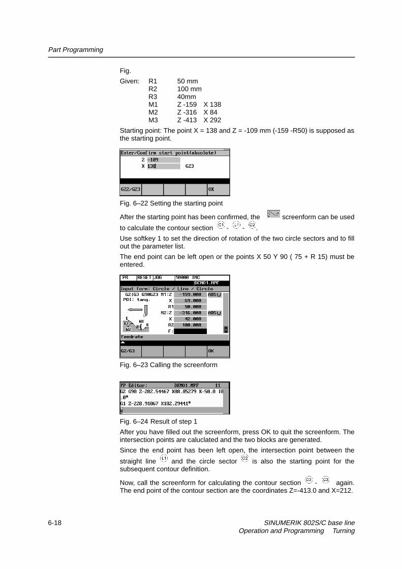
Part Programming
6-18 SINUMERIK 802S/C base line Operation and Programming Turning
Fig.
Given: R1 50 mmR2 100 mmR3 40mmM1 Z -159 X 138M2 Z -316 X 84M3 Z -413 X 292
Starting point: The point X = 138 and Z = -109 mm (-159 -R50) is supposed asthe starting point.
Fig. 6–22 Setting the starting point
After the starting point has been confirmed, the screenform can be used
to calculate the contour section - - .
Use softkey 1 to set the direction of rotation of the two circle sectors and to fillout the parameter list.
The end point can be left open or the points X 50 Y 90 ( 75 + R 15) must beentered.
Fig. 6–23 Calling the screenform
Fig. 6–24 Result of step 1
After you have filled out the screenform, press OK to quit the screenform. Theintersection points are caluclated and the two blocks are generated.
Since the end point has been left open, the intersection point between the
straight line and the circle sector is also the starting point for thesubsequent contour definition.
Now, call the screenform for calculating the contour section - again.The end point of the contour section are the coordinates Z=-413.0 and X=212.

Part Programming
SINUMERIK 802S/C base line 6-19Operation and Programming Turning
Fig. 6–25 Calling the screenform
Fig. 6–26 Result of step 2
This function is used to insert a circle sector tangentially between two adjacentcircle sectors. The circle sectors are described by their center points and theircircle radii. The inserted sector is described by its radius.
Use the screenform to enter the parameters center point and radius for circlesector 1, and the parameters end point, center point and radius for circle sector2. in addition, the radius for the inserted circle sector 3 must be entered and thedirection of rotation be defined.
The end point and the center points can be acquired either as absolute,incremental or polar coordinates.
The selected setting is displayed in a help screen.
The OK function will caluclate three blocks from the given values and will insertthem into the part program.
Fig. 6–27 Screenform for calculating the contour section ’circle - circle - circle

Part Programming
6-20 SINUMERIK 802S/C base line Operation and Programming Turning
Table 6–6 Input in the dialog screenform
End point E 1st and 2nd geometry axes of the planeIf no coordinates are entered, the functionprovides the intersection point between theinserted circle sector and sector 2.
Center point of circle 1 M1 1st and 2nd geometry axes of the planeRadius of circle 1 R1 Input field for radius 1Center point of circle 2 M2 1st and 2nd geometry axes of the planeRadius of circle 2 R2 Input field for radius 2Radius of circle 3 R3 Input field for radius 3Feedrate F Input field for the interpolation feed
If the starting point cannot be deteremined from the previous blocks, therespective coordinates must be entered in the “Starting point” screenform.
G2/G3 This softkey defines the direction of rotation of the three circles. It is possible to
select between:
Sector 1 Inserted Sector Sector 2G2 G 3 G2,G2 G2 G2,G2 G2 G3,G2 G3 G3,G3 G2 G2,G3 G3 G2,G3 G2 G3,
Example DIAMON - G23
Fig.6-28
Given: R1 39 mmR2 69 mmR3 39 mmR4 49 mmR5 39 mmM1 Z -111 X 196M2 Z -233 X 260M3 Z -390 X 162

Part Programming
SINUMERIK 802S/C base line 6-21Operation and Programming Turning
The coordinates Z -72, X 196 will be selected as the starting point.
After you have confirmed the starting point, use the screenform to
caluclate the contour section - . The end point is left open, since thecoordinates.
Use softkey 1 to set the direction of rotation of the two circles (G2 - G3 - G2)and to fill out the parameter list.
Fig. 6–29 Setting the starting point
Fig. 6–30 Screenform ’circle - circle - circle’
Fig.6-31 Result of step 1
In the second step, screenform is used to calculate the contour section
- . For calculation, select direction of rotation G2 - G2 - G3. Starting pointis the end point of the first caluclation.

Part Programming
6-22 SINUMERIK 802S/C base line Operation and Programming Turning
Fig. 6–32 Screenform ’circle - circle - circle’
Fig. 6–33 Result of step 2
The result provided by the function is the intersection point between circlesector 4 and circle sector 5 as the end point.
To caluclate the tangential transition between and , the circle-straightline screenform is used.
Fig. 6–34 Screenform ‘circle - straight line’

Part Programming
SINUMERIK 802S/C base line 6-23Operation and Programming Turning
Fig. 6–35 Result of step 3
This function is used to insert a circle sector (with tangential transitions)between two straight lines. The circle sector is described by the center pointand the radius. The coordinates of the end point of the second straight line and,optionally, angle A2. The first straight line is described by the starting point andthe angle A1.
If the starting point cannot be determined from the previous blocks, the startingpoint must be set by the operator.
Fig. 6–36 Straight line - circle - straight line
Table 6–7 Input in the interactive screenform
End point of straight line 2 E Enter the end point of the straight line.
Circle center point M 1st and 2nd axes of the planeAngle of straight line 1 A1 The angle must be specified in the CCW
direction.Angle of straight line 2 A2 The angle must be specified in the CCW
direction.Feedrate F Input field for the feedrate
End and center points can be specified either in absolute, incremental or polarcoordinates. The screenform will generate a circle and two straight line blocksfrom the entered data.
Use this softkey to switch the direction of rotation from G2 to G3. G3 isdisplayed on the screen. Pressing this softkey once more will switch back toG2; the display will change to G2.
G2/G3

Part Programming
6-24 SINUMERIK 802S/C base line Operation and Programming Turning
6.3.4 Free softkey assignment
You can assign the softkeys various cycles or contours. To this aim, thesoftkeys 1 to 4 in the softkey bar in the Program operating area are provided.
Once you have activated the Assign softkeys function, a list of all availablecycles or contours appears on the screen.
Fig.6-37
Position the cursor on the element you wish to assign.
Press the desired softkey from 1 to 4 to assign them the desired element. Theassignment you have made appears in the softkey bar under the selection list.
Confirm the assignment you have made by selecting the OK softkey.
AssignSK
OK
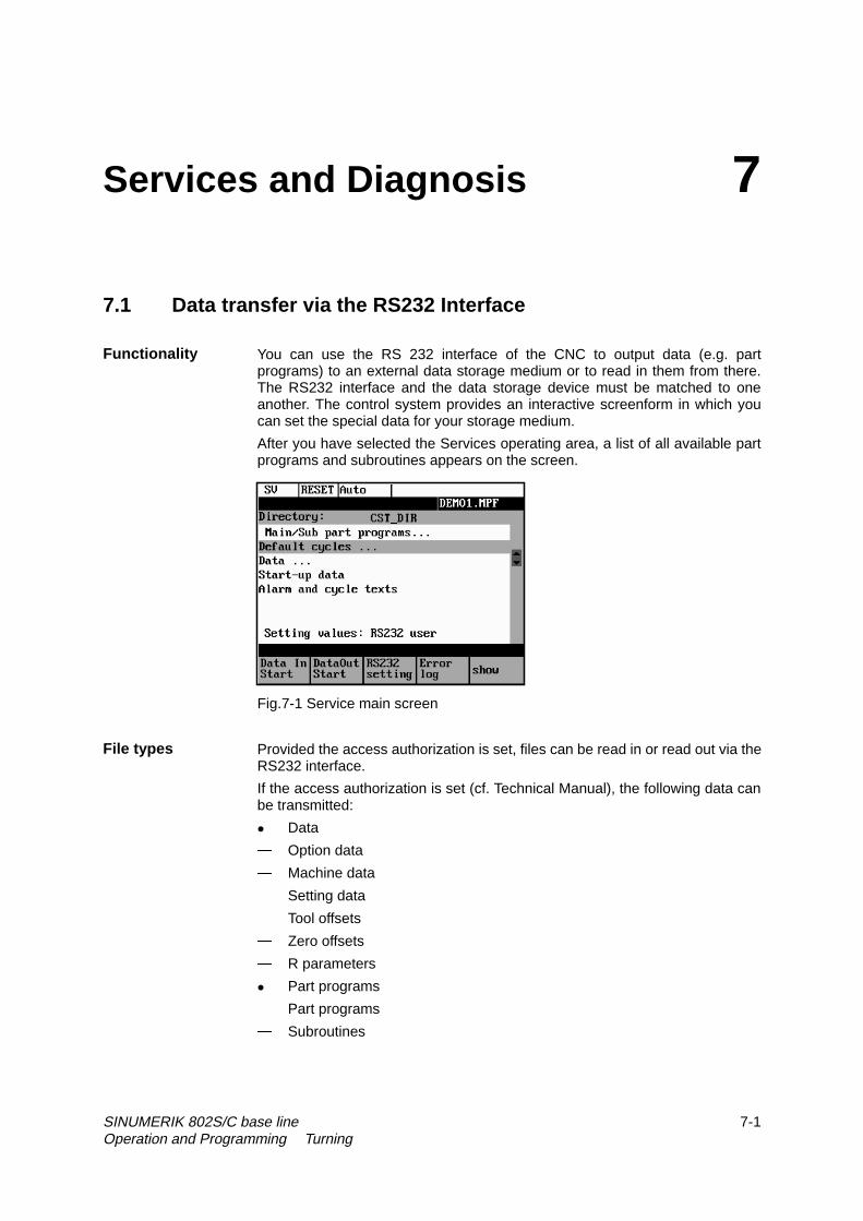
SINUMERIK 802S/C base line 7-1Operation and Programming Turning
Services and Diagnosis 7
7.1 Data transfer via the RS232 Interface
Functionality You can use the RS 232 interface of the CNC to output data (e.g. partprograms) to an external data storage medium or to read in them from there.The RS232 interface and the data storage device must be matched to oneanother. The control system provides an interactive screenform in which youcan set the special data for your storage medium.
After you have selected the Services operating area, a list of all available partprograms and subroutines appears on the screen.
Fig.7-1 Service main screen
File types Provided the access authorization is set, files can be read in or read out via theRS232 interface.
If the access authorization is set (cf. Technical Manual), the following data canbe transmitted:
z Data
� Option data
� Machine data
� Setting data
� Tool offsets
� Zero offsets
� R parameters
z Part programs
� Part programs
� Subroutines

Services and diagnosis
7-2 SINUMERIK 802S/C base line Operation and Programming Turning
z Start-up data
� NCK data
� PLC data
� Alarm texts
z Compensation data
� Leadscrew pitch/encoder errors
z Cycles
� Standard cycles
Operating Sequence
Use the Service softkey to select the Services operating area.
Softkeys
This key starts reading in data.
This key starts reading out data to the PG/PC or another device.
With the access authorization set, this function can be used to modify theinterface parameters and to save them.
Fig. 7–2 Interface settings
Position the cursor on the desired data.
Use the selection key to modify the settings in the left column. The specialfunctions can be activated and deactivated by the Select key.
Activating the transmission log
These softkeys are intended to adapt the RS232 interface to the transmissionlog. 2 logs are set by default.
Use this softkey to produce a log for the transfer of data, part programs andcycles.
Use this softkey to produce a log for the transfer of start-up data.The baud ratecan be adapted according to the receiver.
Data InStart
DataOutStart
RS232setting
RS232text
RS232binary
Service

Services and diagnosis
SINUMERIK 802S/C base line 7-3Operation and Programming Turning
Press this softkey to save your settings.
Select RECALL to exit the window without saving your settings.
A log is output for the transferred data.
z For files to be output, it contains
� the file name and
� an error acknowledgement
z For imported files, it contains
� the file name and the path specification
� an error acknowledgement
Transmission messages:
OK Transmission completed successfullyERR EOF End-of-file character received, but the archive file is not
complete.Time Out Timeout monitoring is signaling an interruption in the
transmission.User Abort Transmission aborted by Stop softkeyError Com Error at COM 1NC / PLC Error NC error messageError Data Data errors
1. Files read in with/without leaderor2. Files transferred in tape format without file name
Error File Name The file name does not comply with NC nameconventions.
no access right No access right for this function
Display of the data that are amongst the data types marked with “...”. Use thisfunction to transfer individual files.
Menu extension
An external program is transferred to the control system via the RS232interface and executed immediately by pressing NC Start (see Section 5.5).
Note
As an alternative, program execution from external can also be activated in theAutomatic area.
OK
Errorlog
Show
Executf. ext.

Services and diagnosis
7-4 SINUMERIK 802S/C base line Operation and Programming Turning
7.1.1 Interface parameters
Table 7–1 Interface parameters
Parameter DescriptionDevice type • XON/XOFF
One possible method of controlling the transmission operationis to use the XON (DC1, DEVICE CONTROL 1) and XOFF(DEVICE CONTROL 2) control characters. As soon as thebuffer of the I/O device is full, it returns XOFF, and as soon asit can receive data again, it sends XON.• RTS/CTSThe RTS signal ( Request to Send) controls the sendoperation of the data transmission device.Aktive signal: Send dataPassive signal: Do not exit send mode until all transferreddata have been sent.The CTS signal is the acknowledgment signal for RTS andindicates that the data transmission device is ready to send.
XON This is the character that is used to start transmission. It iseffective only for device type XON/XOFF.
XOFF This is the character with which data transmission is stopped.End oftransmission
This is the character that signals end of transmission of a textfile.The special function “Stop with end of transmission” charactermay not be active if binary data are to be transferred.
Baud rate Interface speed settings300 baud600 baud1200 baud2400 baud4800 baud9600 baud19200 baud38400 baud
Data bits Number of data bits for asynchronous transmission.Input:7 data bits8 data bits (default)
Stop bits Number of stop bits for asynchronous transmission.Input:1 stop bit (default)2 stop bits
Parity Parity bits are used to detect errors. These are added to thecoded character in order to obtain either an even or oddnumber of positions set to “1”.Input:No parity (default)Even parityOdd parity

Services and diagnosis
SINUMERIK 802S/C base line 7-5Operation and Programming Turning
7.1.2 Special functions
Table 7–2 Special functions
Function Active InactiveStart with XON Transmission starts if the transmitter
receives an XON character in thedata flow.
Transmission startsindependently of anyXON character.
Overwrite withcnfimation
When a file is imported, a check ismade for an existing file of the samename in the NC.
The files areoverwritten withoutconfirmation request.
End of blockwith CR LF
CR characters (hexadecimal 0D) areinserted with tape format outputs.
No additionalcharacters areinserted.
Stop at end oftransmission
The end-of-transmission character isactive.
The character is notevaluated.
Evaluate DSRsignal
Transmission is interrupted if theDSR signal is missing.
DSR signal has noeffect.
Leader andtrailer
Leader is skipped when data arereceived. A leader with 120 * 0 h isgenerated when data are output.
Leader and trailer areread in with otherdata.No leader isgenerated when dataare output.
Tape format Import of part programs Import of archives intheSINUMERIK archiveformat
Timeoutmonitoring
Transmission is interrupted after 5seconds in case of transmissionproblems.
No abortion oftransmission
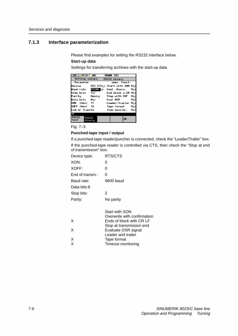
Services and diagnosis
7-6 SINUMERIK 802S/C base line Operation and Programming Turning
7.1.3 Interface parameterization
Please find examples for setting the RS232 interface below.
Start-up data
Settings for transferring archives with the start-up data
Fig. 7–3
Punched-tape input / output
If a punched-tape reader/puncher is connected, check the “Leader/Trailer” box.
If the punched-tape reader is controlled via CTS, then check the “Stop at endof transmission” box.
Device type: RTS/CTS
XON: 0
XOFF: 0
End of transm.: 0
Baud rate: 9600 baud
Data bits:8
Stop bits: 2
Parity: No parity
Start with XONOverwrite with confirmation
X Ends of block with CR LFStop at transmission end
X Evaluate DSR signalLeader and trailer
X Tape formatX Timeout monitoring

Services and diagnosis
SINUMERIK 802S/C base line 7-7Operation and Programming Turning
Parameters for a serial printer
A printer with a serial interface is connected via an appropriate cable (cablecheck at CTS).
Device type: RTS/CTS
XON: 11(H)
XOFF: 13(H)
End of transm.: 1A(H)
Baud rate: 9600 baud
Data bits:8
Stop bits: 1
Parity: No parity
Start with XONOverwrite with confirmation
X End of block with CR LFStop at transmission end
X Evaluate DSR signalX Leader and trailerX Tape formatX Timeout monitoring
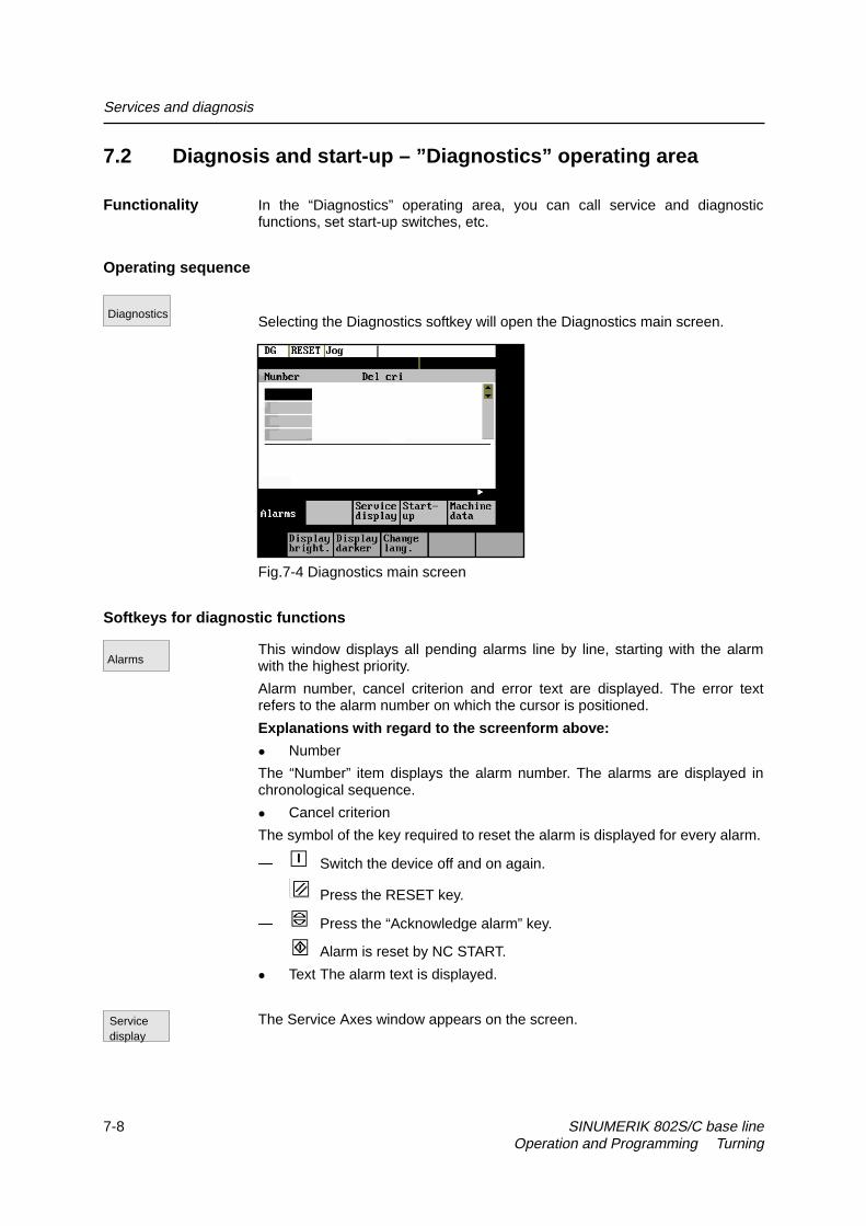
Services and diagnosis
7-8 SINUMERIK 802S/C base line Operation and Programming Turning
7.2 Diagnosis and start-up – ”Diagnostics” operating area
Functionality In the “Diagnostics” operating area, you can call service and diagnosticfunctions, set start-up switches, etc.
Operating sequence
Selecting the Diagnostics softkey will open the Diagnostics main screen.
Fig.7-4 Diagnostics main screen
Softkeys for diagnostic functions
This window displays all pending alarms line by line, starting with the alarmwith the highest priority.
Alarm number, cancel criterion and error text are displayed. The error textrefers to the alarm number on which the cursor is positioned.
Explanations with regard to the screenform above:
z Number
The “Number” item displays the alarm number. The alarms are displayed inchronological sequence.
z Cancel criterion
The symbol of the key required to reset the alarm is displayed for every alarm.
� Switch the device off and on again.
� Press the RESET key.
� Press the “Acknowledge alarm” key.
� Alarm is reset by NC START.
z Text The alarm text is displayed.
The Service Axes window appears on the screen.
Diagnostics
Alarms
Servicedisplay

Services and diagnosis
SINUMERIK 802S/C base line 7-9Operation and Programming Turning
The window displays information about the axis drive.
Fig. 7–5 The “Service Axes” window
In addition, the Axis+ and Axis– softkeys are displayed. They can be used tocall the values for the next or previous axis.
To optimize the drives, an oscillograph function is provided for graphicalrepresentation of the velocity setpoint. The velocity setpoint corresponds to the± 10V interface.
The start of recording can be linked with various criteria which permit recordingin parallel to internal conditions of the control system. The setting needed forthis option must be carried out in the “Select Signal” function.
The following functions can be used to analyze the result:
z Change scaling of abscissa and ordinate,
z Measure value by means of a horizontal or vertical marker,
z Measure the abscissa and ordinate values as a difference between twomarker positions.
Fig. 7–6 The “Servo Trace” main screen
The heading of the diagram contains the current graduation of abscissa andordinate, the current measured positions and the difference values of themarkers.
The displayed diagram can be moved within the visible screen area by meansof the cursor keys.
Serviceaxes
Servotrace

Services and diagnosis
7-10 SINUMERIK 802S/C base line Operation and Programming Turning
Graduation of abscissa
Graduation of ordinate
Initial valuesCurrent marker position
Difference displayof Markers
Fig. 7–7 Meaning of the fields
Use this menu to select the axis to be measured, the measuring time, thresholdvalue, pre-trigger/post-trigger time and trigger conditions. The signal settingsare fixed.
Fig. 7–8 Signal selection
z Selecting the axis: The axis is selected in the Axis toggle field.
z Signal type:Velocity setpointActual position value of measuring system 1Following error
z Determining the measuring time: The measuring time is entered in msdirectly in the “Measuring Time” input field.
z Determining trigger time to or after
With input values < 0, recording starts by the set time prior to the trigger event,and with values > 0 accordingly after the trigger event, whereby the followingconditions must be observed:Trigger time + measuring time ≥ 0.
z Selecting the trigger condition: Position the cursor on the TriggerCondition field and select the condition using the toggle key.
� No trigger, i.e. the measuring starts immediately after pressing the Startsoftkey.
� Negative edge
� Exact stop fine reached
� Exact stop coarse reached
Selectsignal

Services and diagnosis
SINUMERIK 802S/C base line 7-11Operation and Programming Turning
z Determining the trigger threshold: The threshold is entered directly in theThreshold input field. It acts only for the trigger conditions “Positive edge”and “Negative edge”.
This function branches to another softkey level, in which the horizontal orvertical marker can be switched on or off. The markers are displayed in thestatus bar.
The markers are moved in steps of one increment by means of the cursor keys.Larger step widths can be set in the input fields. The value specifies thenumber of raster units per <SHIFT> + cursor movement by which the marker isto be moved.
If a marker reaches the margin of the diagram, the next raster in horizontal orvertical direction is automatically pulled down.
Fig. 7–9 Setting the markers
The markers can also be used to determine the differences in the horizontal orvertical direction. To this aim, position the marker on the start point and presseither the Fix H - Mark. or the Fix T- Mark. softkey. The difference between thestart point and the current marker position is now displayed in the status bar.The softkey labeling changes to “Free H - Mark.” or “Free T - Mark.”.
Pressing this functions calls explanations with regard to the displayed valueson the screen.
Pressing the Start softkey starts recording. The softkey labeling changes toStop. The note “Recording active” is displayed.
When the measuring time is elapsed, the softkey labeling changes to Start.
Pressing the Stop softkey aborts the current measuring. The softkey labelingchanges to Start.
The scaling changes in the following steps:
1, 2, 5, 10, 20, 50, 100, 200, 500, 1,000 ms/div.
The horizontal scaling changes in the following steps:
0.01, 0.05, 0.1, 0.5, 1, 5, 10, 50, 100, 500, 1,000, 5,000 unit/ div
This function calculates the vertical scaling from the peak values.
Marker
Help
Start
Stop
ZoomTime +
ZoomV +
Auto.scaling
ZoomTime –
ZoomV –

Services and diagnosis
7-12 SINUMERIK 802S/C base line Operation and Programming Turning
This window contains the version numbers and the creation date of theindividual CNC components.
displays the control type
Fig. 7–10 Control type
OEMdisplays the OEM picture here.
Softkeys for start-up functions
Note
See also Technical Manual
The start-up function branches to the following softkey functions:
Fig. 7–11
Version
Type
Start-up

Services and diagnosis
SINUMERIK 802S/C base line 7-13Operation and Programming Turning
Start-up switch
You can assign the system power-up parameters various parameters.
Caution
Changes in the start-up branch have a considerable influence on the machine.
Selecting the power-up mode of the NC.
Fig. 7–12 NC Start-up
Fig. 7–13 PLC start-up
The PLC can be started in the following modes:
z Restart
z General reset
In addition, it is possible to link the selected mode with
z subsequent simulation or
z subsequent debugging mode.
Use the OK key to start the NC start-up.
Return to the Start-up main screen without further action by RECALL.
This function can be used to insert or modify PLC alarm messages. Select thedesired alarm number using the softkey function “Next Number”. The textcurrently valid is displayed in the window and in the input line.
Start-upswitch
NC
PLC
OK
Edit PLC txt
!

Services and diagnosis
7-14 SINUMERIK 802S/C base line Operation and Programming Turning
%
Fig. 7–14 Screenform for editing a PLC alarm text
Enter the new text in the input line. Complete your input by pressing INPUT.
For the notation of the texts refer to the Start-up Guide.
This function selects the next following text number for editing. When the lasttext number is reached, the process restarts with the first number.
This function selects the entered number for editing.
Pressing this function saves the modified texts. The editor is then quitted.
The editor is quitted without saving the changes.
Editing Chinese charactersThis function is only available if a Chinese character set is loaded.
The editor shows a section of Chinese characters. Use the cursor to navigatein the list. If the character you are looking for is not contained in the section,another section can be selected using the letters A - Z. Pressing softkey 4takes over the desired character to the input line. In this mode, Latin letterscannot be entered.
Fig. 7–15 screenform for editing a PLC alarm text in Chinese
The following softkey functions are realized:
This function selects the next following text number for editing. When the lasttext number is reached, the process restarts with the first number.
Next Number
Search Number
Save & Exit
Recall
Next Number

Services and diagnosis
SINUMERIK 802S/C base line 7-15Operation and Programming Turning
This function selects the entered number for editing.
This function toggles between the selection of the section and the input of Latinletters.
Pressing this softkey accepts the selected character into the input line.
Pressing this softkey saves the modified texts. The editor is then quitted.
The editor is quitted without saving the changes.
The S7-Conn menu can be used to link the PLC with the external programmingpackage S7-200.
If the RS232 interface is already occupied by the data transfer, you can link thecontrol system with the programming package only when the transmission iscompleted.
When the link is activated, the RS232 interface is initialized. The followinginterface parameters are defined by the used program:
Device RTS - CTS
Baud rate 38400
Stop bits 1
Parity even
Data bits 8
Fig. 7–16 S7-200 Connection
This function activates the connection between the PC and the control system.The softkey labeling changes to Connection off (Conn. off).
The active or inactive condition, respectively, is maintained even if Power On iscarried out (except for booting with default data).
Press RECALL to quit the menu.
You can display information about the current states of PLC memory cellslisted below; if desired they can be altered.
It is possible to display 6 operands simultaneously.
Search Number
Change Mode
Choose Char
Save & Exit
Recall
STEP 7 connect
Conn.on
PLC status
Conn.off

Services and diagnosis
7-16 SINUMERIK 802S/C base line Operation and Programming Turning
Inputs I Input byte (IBx), input word (Iwx), input double word (IDx)Outputs Q Output byte (Qbx), output word (Qwx), output double word
(QDx)Bitmemories
M Memory byte (Mx), memory word (Mw), memory doubleword (MDx)
Timers T Timer (Tx)Counters C Counter (Zx)Data V Data byte (Vbx), data word (Vwx), data double word (VDx)Format B
HD
BinaryHexadecimalDecimalBinary representation cannot be used for double words.Counters and timers are displayed in decimal format.
Fig. 7–17 PLC status display
There are further softkeys provided under this menu item.
z Edit
Cyclic updating of the values is interrupted. You can then edit the operandvalues.
z Cancel
Cyclic updating continues without the entered values being transferred to thePLC.
z Accept
The entered values are transferred to the PLC; cyclic updating continues.
z Delete
All operands are deleted.
z Operand +
The address of the operand can be incremented in steps of 1.
z Operand –
The address of the operand can be decremented in steps of 1.
Set password
There are four different password levels implemented by the control system,thereby allowing four different levels of access authorization:
Set password

Services and diagnosis
SINUMERIK 802S/C base line 7-17Operation and Programming Turning
z Siemens password
z System password
z Manufacturer password
z User password
You can edit the data depending on your level of access authorization (referalso to the Technical Manual)
DEMO.MPF
Enter the password.
If you do not know the password, you will not be granted access.
The password is set when you press the OK softkey.
You can return to the Start-up main screen without saving your input byselecting RECALL.
The access authorization is reset.
Change password
Fig. 7–18
Depending on the access authorization, various options for changing thepassword are provided in the softkey bar.
Use the softkeys to select the password level. Enter the new password andcomplete your input with OK.
The system asks you to confirm the new password again.
Press OK to complete the password change.
You can return to the Start-up main screen without saving your input byRECALL.
Save data
This function saves the contents of the volatile memory to a non-volatilememory area.
Delete password
Change password
Save data

Services and diagnosis
7-18 SINUMERIK 802S/C base line Operation and Programming Turning
Prerequisite: No program is currently being run.
It is not allowed to perform any operating actions while saving data.
Softkeys for service functions
Machine data (see also Technical Manual)
Fig.7-19
Changes to the machine data have a considerable influence on the machine.Incorrect parameter settings can result in irreparable damage to mechanicalcomponents.
userdef User-definedM/s**2 Meters per secondU/s**3 Revolutions per secondS SecondKgm**2 Moment of inertiaMH InductivityNm Torqueµs MicrosecondsµA Microamperes
Units
µVs Microvolt secondsSo Effective immediatelyCf With confirmationRe Reset
Effectiveness
Po Power ON
General machine data
Open the General Machine Data window. Use the paging keys to page up anddown.
Axis-specific machine data
Open the Axis-Specific Machine Data window. The softkey bar is extended bythe Axis + and Axis – softkeys.
Fig.7-20
The data of the axis are displayed.
Machine data
General MD
Axis MD

Services and diagnosis
SINUMERIK 802S/C base line 7-19Operation and Programming Turning
Other machine data
Open the Other Machine Data window. Use the paging keys to page up anddown.
Display machine data
Open the Display Machine Data window. Use the paging keys to page up anddown.
Search
Enter the number or name of the machine data you want to find and pressInput.
The cursor jumps to the target data.
Fig. 7–21
The search for the next number or name continues.
The Axis + and Axis – softkeys are used to switch over to the machine dataarea of the next or previous axis.
This softkey is used to activate the machine data marked with “cf”.
Brightness
This softkey can be used to adjust the brightness of the screen.
The power-up setting can be input via a display machine data. The adjustmentvia these softkeys does not effect the setting in the display machine data.
Switching the language
Use the Change lang. softkey to switch between foreground and backgroundlanguages.
Other MD
Display MD
Search
Continue search
Axis +
Active MD
Displaybright.
Changelang.
Axis –
Displaydarker

Services and diagnosis
7-20 SINUMERIK 802S/C base line Operation and Programming Turning

SINUMERIK 802S/C base line 8-1Operation and Programming Turning
Programming 8
8.1 Fundamentals of NC programming
8.1.1 Program structure
Structure and contents
The NC program consists of a sequence of blocks (see Table NO TAG).
Each block constitutes a machining step.
Instructions are written in a block in the form of words.
The last block in the sequence contains a special word for the end of program:M2.
Table 8–1 NC program structure
Block Word Word Word ... ; CommentBlock N10 G0 X20 ... ; 1st blockBlock N20 G2 Z37 ... ; 2nd blockBlock N30 G91 ... ... ; ...Block N40 ... ... ...Block N50 M2 ; End of program
Program names Every program has its own program name.
Note
When generating the program, its name can be freely chosen provided thefollowing conditions are complied with:
z The first two characters must be letters;
z otherwise letters, digits or underscore may be used.
z Do not use more than 8 characters.
z Do not use separators (see Section “Character Set”)
Example: SHAFT52/

Programming
8-2 SINUMERIK 802S/C base line Operation and Programming Turning
8.1.2 Word structure and address
Functionality/structure The word is an element of a block and is mainly a control instruction.
The word (see Fig. (8-1) consists of
z an address character
The address character is generally a letter,
z and a numerical value.
The numerical value consists of a sequence of digits. A preceding sign or adecimal point can be added to this sequence for certain addresses.
A positive sign (+) can be omitted.
Fig.8-1 word structure
Several address characters A word may also contain several address letters. In such cases, however, an
“=” sign must be inserted to assign the numerical value to the address letters.Example: CR=5.23
Word
Address Value
Example: G1 X–20.1 F300
Word
Address Value
Word
Address Value
Explanation: Traversewith linearinterpolation
Path or endposition for Xaxis: -20.1 mm
Feed:300 mm/min

Programming
SINUMERIK 802S/C base line 8-3Operation and Programming Turning
8.1.3 Block structure
Functionality A block should contain all data required to execute a machining step.
The block generally consists of several words and always ends with the end-of-block character “LF” (line feed). This character is automatically generatedwhen the carriage return or Input key is pressed during typing.
/N… Word1 Word2 … Wordn ;Comment LF
end-of-blockcharacter notvisibleOnly if needed,
positioned atseparated from rest ofby ;
BLANK BLANK BLANK BLANK
Block instructionsBlock number, written beforestatements, only ifcharacter N is replaced
character : in main blocksSkip block, only ifpositioned at the Total number of characters in a block:
Fig.8-2 Diagram of block structure
Word sequence When a block contains more than one statement, the words in the block shouldbe arranged in the following sequence:
N... G... X... Y... Z... F... S... T... D... M...
Note with regard to the block numbers Select the block numbers first in steps of 5 or 10. This will allow you to insert
blocks later while retaining the ascending order of the block numbers.
Block skipping (see Fig. 5–3) Program blocks that must not be executed during every program run can be
marked with a slash “ / ” in front of the block number word.Block skipping is activated by means of an operator input or by the interfacecontrol (signal). A program section can be skipped by skipping severalsuccessive blocks with “ / ”.If block skipping is active during program execution, none of the blocks markedwith “ / ” is executed. Any statements contained in such blocks are ignored.The program continues at the next block not marked.
Comment, remark Comments (remarks) can be used to explain the staements in the blocks of aprogram.Comments are displayed together with the other contents of the block in thecurrent block display.
Programming example N10 ;G&S Order No. 12A71
N20 ;Pump part 17, Drawing No.: 123 677N30 ;Program created by Mr. Adam Dept.TV 4

Programming
8-4 SINUMERIK 802S/C base line Operation and Programming Turning
:50 G17 G54 G94 F470 S20 D0 M3 ;Main blockN60 G0 G90 X100 Y200N70 G1 Y185.6N80 X112/N90 X118 Y180 ;Block can be skippedN100 X118 Y120N110 X135 Y70N120 X145 Y50N130 G0 G90 X200N140 M2 ;End of program

Programming
SINUMERIK 802S/C base line 8-5Operation and Programming Turning
8.1.4 Character set
The following characters can be used for programming and are interpretedaccording to the following definitions:
Letters A, B, C, D, E, F, G, H, I, J, K, L, M, N,O, P, Q, R, S, T, U, V, W X, Y, Z
No distinction is made between upper-case and lower-case letters.Lower-case letters are therefore equivalent to upper-case letters.
Digits 0, 1, 2, 3, 4, 5, 6, 7, 8, 9
Printable special characters ( Left round bracket
) Right round bracket[ Left square bracket] Right square bracket< Less than> Greater than: Main block, label termination= Assignment, equals/ Division, block skip* Multiplication+ Addition, positive sign- Subtraction, negative sign“ Quotation marks_ Underscore (together with letters). Decimal point, Comma, separator; Start of comment% Reserved, do not use& Reserved, do not use’ Reserved, do not use$ Reserved, do not use? Reserved, do not use! Reserved, do not use
Non-printable special characters LF End-of-block character
Blank Separator between words, blankTabulator Reserved, do not use.

Programming
8-6 SINUMERIK 802S/C base line Operation and Programming Turning
8.1.5 Overview of instructions
Address Meaning Value assignment Information ProgrammingD Tool
compensationnumber
0 ... 9, integers only,without sign
Contains compensation data for aparticular tool T... ; D0->compensationvalues= 0,max. 9 D numbers for one tool
D...
F Feedrate(in combination
with G4, thedwell time is also
programmedunder F)
0.001 ... 99 999.999 Tool/workpiece path velocityin mm/min or mm/revdepending on whether G94 or G95 isprogrammed
F...
G G function(preparatoryfunction)
Only specific integervalues
The G functions are divided into Ggroups. Only oneG function of a G group can beprogrammed in any one block.A G function can be modal (untilcanceled by another function of thesame group) or non-modal - it is onlyactive for the block in which it isprogrammed.G group:
G...
G0 Linear interpolation with rapid traverse G0 X... Z...G1 * Linear interpolation with feed G1 X... Z... F...G2 Circular interpolation in clockwise
directionG2 X... Z... I... K...F...;center point andend pointG2 X... Z... CR=...F...;Radius and endpointG2 AR=... I... K...F...;Angle of apertureand center pointG2 AR=... X... Z...F...;Angle of apertureand end point
G3 Circular interpolation incounterclockwise direction
G3 .... ;otherwiseas for G2
G5 Circular interpolation via interpolationpoint
1: Motion commands (interpolation type)
G5 X...Z...IX=...KZ=... F...
G33 Thread cutting with constant pitch Modal G33 Z... K... SF=...;Cylindrical threadG33 X... I... SF=...;Cross threadG33 Z... X... K...SF=...;Tapered thread,path greater in Zaxis than in X axisG33 Z... X... I...SF=...;Tapered thread,path greater in Xaxis than in Z axis

Programming
SINUMERIK 802S/C base line 8-7Operation and Programming Turning
Address Meaning Value assignment Information ProgrammingG4 Dwell time G4 F... or G4
S....;in separate block
G74 Reference point approach G74 X...Z...;in separate block
G75 Fixed point approach
2: Special movements,non modal
G75 X... Z...;in separate block
G158 Programmable offset G158 X...Z...;in separate block
G25 Lower spindle speed limit G25 S...;in separate block
G26 Upper spindle speed limit
3: Write to memorynon modal
G26 S...;in separate block
G17 (required for center drilling)G18 * Z/X plane
6: Plane selection
G40 * Tool radius compensation OFFG41 Tool radius compensation left of contourG42 Tool radius compensation right of
contour
7: Tool radius compensationmodal
G500 * Settable zero offset OFFG54 1st settable zero offsetG55 2nd settable zero offsetG56 3rd settable zero offsetG57 4th settable zero offset
8: Settable zero offsetmodal
G53 Non–modal suppression of settablezero offset
9: Suppression of settable zero offsetnon modal
G60 * Exact positioningG64 Continuous path mode
10: Approach behaviourmodal
G9 Non-modal exact stop 11: Non–modal exact positioningnon–modal
G601 * Exact positioning window fine for G60,G9
G602 Exact positioning window coarse forG60, G9
12: Exact positioning windowmodal
G70 Dimensions in inchesG71 * Dimensions in metric values
13: Dimensions in inches/metric valuesmodal
G90 * Absolute dimensionsG91 Incremental dimensions
14: Absolute/incremental dimensionmodal
G94 Feedrate F in mm/minG95 * Feedrate F in mm/revolution of spindleG96 Constant cutting speed for turning ON
(F in mm/rev, S in m/min)G96 S... LIMS=...F...
G97 Constant cutting speed for turning OFF
15: Feedrate/spindlemodal
G450 * Transition circleG451 Point of intersection
18: Behaviour at corners with tool radiuscompensation
modalG22 Radius inputG23 * Diameter input
29: Radius/diameter inputmodal
The functions marked with an * are active from the beginning of the program (with the versionof the control supplied unless otherwise programmed).

Programming
8-8 SINUMERIK 802S/C base line Operation and Programming Turning
Address Meaning Value assignment Information ProgrammingI Interpolation parameter ± 0.001 ... 99 999.999
thread:0.001 ... 2000.000
For X axis, meaning depends onwhether G2,G3->circle center orG33->thread pitch has beenprogrammed
see G2, G3 andG33
K Interpolation parameter ± 0.001 ... 99 999.999thread:0.001 ... 2000.000
For Z axis, otherwise as for I see G2, G3 andG33
L Subroutine, name andcall
7 decimal places,integers only, withoutsign
Instead of a user–defined nameL1 ...L9999999 can also beselected;this also calls the subroutine in itsown blockCaution: L0001 is not the sameas L1
L....;in separate block
M Miscellaneous function 0 ... 99integers only, no sign
E.g. to trigger actionssuch as ”coolant ON”,max. 5 M functions in one block,
M...
M0 Programmed stop Machining is stopped at the endof a block containing M0,operation is continuedwith ”START”
M1 Optional stop As for M0, but operation onlystops if a special signal has beengiven
M2 End of program Programmed in the last block tobe executed
M30 - Reserved, do not useM17 - Reserved, do not useM3 Spindle clockwise rotationM4 Spindle counterclockwise rotationM5 Spindle stopM6 Tool change Only if activated with M6 in
machine data,otherwise toolchange performed directly with Tcommand
M40 Automatic gear stage switchoverM41 bisM45
Gear stage 1 togear stage 5
M70 - Reserved, do not useM... Other M functions This functionality is not
predefined in the control and cantherefore be assigned by themachine manufacturer
N Block number -subblock
0 ... 9999 9999integer only, no sign
Can be used with a number toidentify blocks,programmed at the beginning ofa block
E.g.: N20
: Block number - mainblock
0 ... 9999 9999integer only, no sign
Special identification for blocks -used instead of N..., this blockshould contain all the instructionsfor a complete set of subsequentmachining operations
E.g.: 20
P Number of subroutinepasses
1 ... 9999integer only, no sign
Programmed in the same blockas a subroutine to be calledseveral times,e.g.: N10 L871 P3 ; called threetimes
E.g.: L781 P...;in separate block

Programming
SINUMERIK 802S/C base line 8-9Operation and Programming Turning
Address Meaning Value assignment Information ProgrammingR0toR249
Arithmetic parameter ± 0.0000001 ... 99999999(8 decimal places) orwith exponent:± (10-300 ... 10+300 )
R0 to R99 -user assignableR100 to R249 -transferparameters for machining cycles
Arithmetic functions In addition to the 4 basicarithmetic operations+ - * / the followingarithmetic functions are alsoavailable:
SIN( ) Sine in degrees E.g.:R1=SIN(17.35)
COS( ) Cosine in degrees E.g.:R2=COS(R3)
TAN( ) Tangent in degrees E.g.:R4=TAN(R5)
SQRT( ) Square root E.g.:R6=SQRT(R7)
ABS( ) Absolute value E.g.:R8=ABS(R9)
TRUNC( ) Integer part E.g.:R10=TRUNC(R11)
RET End of subroutine 0.001 ... 99 999.999 Used instead of M2 to maintaincontinuous path mode
RET ;in separate block
S Spindle speedor other meaningwithG4, G96
0.001 ... 99 999.999 Spindle speed in rev/minif G96 is programmed, S isinterpreted as constant cuttingspeed in m/min (turning),with G4, dwell time in spindlerevolutions
S...
T Tool number 1 ... 32 000integer only, withoutsign
Tool change can be performeddirectly with T command or notuntil M6 is programmed. This canbe set in machine data.
T...
X Axis ± 0.001 ... 99 999.999 Positional data X...Z Axis ± 0.001 ... 99 999.999 Positional data Z...AR Angle of aperture for
circular interpolation0.00001 ... 359.99999 Given in degrees, a method of
defining the circle with G2/G3see G2; G3
CHF Chamfer 0.001 ... 99 999.999 Inserts a chamfer of the specifiedlength between two contour blocks
N10 X... Z....CHF=...N11 X... Z...
CR Radius for circularinterpolation
0.010 ... 99 999.999Negative sign - for
circle selection:greater semi-circle
A method of defining a circle withG2/G3.
see G2; G3
GOTOB GOTO instructionbackwards
- Jumps to the block defined by thelabel, the target of the jump islocated in the direction of thebeginning of the program.
E.g.: N20GOTOBMARKE1
GOTOF GOTO instructionforwards
- Jumps to the block defined by thelabel, the target of the jump islocated in the direction of the endof the program.
E.g.: N20GOTOF
MARKE2

Programming
8-10 SINUMERIK 802S/C base line Operation and Programming Turning
Address Meaning Value assignment Information ProgrammingIF Jump condition - If the jump condition is fulfilled
the jump goes to the nextinstruction,
Comparators:= =>>=<=
E.g.: N20 IFR1>5 GOTOB
MARKE1
IX Interpolation point forcircular interpolation
± 0.001 ... 99 999.999 For the X axis, programmed forcircular interpolation with G5
see G5
KZ Interpolation point forcircular interpolation
± 0.001 ... 99 999.999 For the Z axis, programmed forcircular interpolation with G5
see G5
LCYC... Machining cycle call Specified values only Machining cycles have to becalled in a separate block, thetransfer parameters to be usedmust be assigned valuesTransfer parameters:
LCYC82 Drilling, spot-facing R101: Retraction plane(absolute)R102: Safety clearanceR103: Reference plane(absolute)R104: Final drilling depthR105: Dwell time at drilling depth
N10 R100=...R101=... ...N20 LCYC82in separate block
LCYC83 Deep-hole drilling R100: Number of the drilling axis=3R101: Retraction plane(absolute)R102: Safety clearanceR103: Reference plane(absolute)R104: Final drilling depth(absolute)R105: Dwell time at drilling depthR106: Dwell time start/stockremovalR107: First drilling depth(absolute)R108: Amount of degressionR109: Feedrate factor for drillingR110: Machining type:chipbreaking=0 stock removal=1R111: Feedrate for first drillingdepth
N10 R100=...R101=... ....N20 LCYC83;in separate block
LCYC840 Tapping with compensating chuck R101: Retraction plane (absoluteR102: Safety clearanceR103: Reference plane(absolute)R104: Final drilling depth(absolute)R106: Thread lead valueR126: Direction of rotation ofspindle for tapping
N10 R100=...R101=... ....N20 LCYC840;in separate block

Programming
SINUMERIK 802S/C base line 8-11Operation and Programming Turning
Address Meaning Value assignment Information ProgrammingLCYC85 Boring R101: Retraction plane (absolute
R102: Safety clearanceR103: Reference plane(absolute)R104: Final drilling depth(absolute)R105: Dwell time at drilling depthR107: Feed for drillingR108: Feed on retract from drill hole
N10 R100=...R101=... ....N20 LCYC85;in separate block
LCYC93 Groove (drilling cycle) R100: Starting point in facing axisR101: Starting point in longitudinal axisR105: Machining type (1...8)R106: Final machining allowanceR107: Cutting edge widthR108: Infeed depthR114: Groove widthR116: Thread angleR117: Chamfer on groove edgeR118: Chamfer at base of grooveR119: Dwell time at base of groove
N10 R100=...R101=... ....N20 LCYC93;in separate block
LCYC94 Undercut (form E and F) (turning cycle) R100: Starting point in facing axisR101: Starting point of contour in
longitudinal axisR105: Form E=55, F=56R107: Cutting edge position (1...4)
N10 R100=...R101=... ....N20 LCYC94
;inseparate block
LCYC95 Stock removal (turning cycle) R105: Machining type (1...12)R106: Finishing allowanceR108: Infeed depthR109: Infeed angle for roughingR110: Contour clearance for roughingR111: Feedrate for roughingR112: Feedrate for finishing
N10 R105=...R106= ...N20 LCYC95
in separateblock
LCYC97 Thread cutting (turning cycle) R100: Diameter of thread at starting pointR101: Thread starting point in longitudinal axisR102: Thread diameter at end pointR103: Thread end point in longitudinal axisR104: Thread lead valueR105: Machining type (1 and 2)R106: Finishing allowanceR109: Approach pathR110: Run-out pathR111: Thread depthR112: Starting point offsetR113: Number of roughing cutsR114: Number of threads
N10 R100=...R101=... ....N20 LCYC97
;inseparate block
LIMS Upper limit speed ofspindle with G96
0.001 ... 99 999.999 Limits the spindle speed iffunction G96 is activated -
constant cutting speed for turning
see G96
RND Rounding 0.010 ... 99 999.999 Inserts a rounding with the radiusvalue specified tangentiallybetween two contour blocks
N10 X... Z....RND=...N11 X... Z...

Programming
8-12 SINUMERIK 802S/C base line Operation and Programming Turning
Address Meaning Value assignment Information ProgrammingSF Thread
commencement pointwith G33
0.001 ... 359.999 Specified in degrees, with G33the thread commencement pointis offset by the specified amount
see G33
SPOS Spindle position 0.0000 ... 359.9999 Specified in degrees, the spindlestops at the specified position(spindle must be designed to dothis)
SPOS=....
STOPRE Preprocessing stop - Special function, the next block isnot decoded until the block priorto STOPRE is completed
STOPRE ;inseparate block
$P_TOOL Active tool cuttingedge
read-only integer,DO to D9
IF $P_TOOL==7GOTOF ...
$P_TOOLNO
Active tool number read-only integer,TO - T32000
IF$P_TOOLNO==46 GOTOF ...
$P_TOOLP Tool number lastprogrammed
read-only integer,TO - T32000
IF$P_TOOLNP==11 GOTOF ...

Programming
SINUMERIK 802S/C base line 8-13Operation and Programming Turning
8.2 Position data
8.2.1 Absolute/incremental dimensions: G90, G91
Functionality When instruction G90 or G91 is active, the specified position information X, Z isinterpreted as a coordinate point (G90) or as an axis path to be traversed(G91). G90/G91 applies to all axes.
These instructions do not determine the actual path on which the end pointsare reached. This is done by a G group (G0, G1, G2, G3, ... see Section “AxisMovements”).
Programming G90 ;Absolute dimensioningG91 ;Incremental dimensioning
G90 absolute dimension
sion
G91 incremental dimension
sion
Z
X
W
Z
X
W
Fig.8-3 Different dimensioning in the part drawing
Absolute dimension G90 When absolute dimensioning is selected, the dimension data refer to the zero
point of the currently active coordinate system (workpiece coordinate system,current workpiece coordinate system or machine coordinate system). Which ofthe systems is active depends on which offsets are currently effective, i.e.programmable, settable or none at all.
G90 is active for all axes on program start and remains so until it is deactivatedby G91 (incremental dimensioning selection) in a subsequent block (modalcommand).
Incremental dimen- When incremental dimensioning is selected, the numerical value in the posionsion G91 information corresponds to the path to be traversed by an axis. The traversing
direction is determined by the sign.
G91 applies to all axes and can be deactivated by G90 (absolute dimensioning)in a later block.
Programming exam- N10 G90 X20 Z90 ;Absolute dimensioningple for G90 and G91 N20 X75 Z-32 ;Absolute dimensioning still active
...N180 G91 X40 Z20 ;Switchover to incremental dimensioningN190 X-12 Z17 ;Incremental dimensioning still active

Programming
8-14 SINUMERIK 802S/C base line Operation and Programming Turning
8.2.2 Metric/inch dimensions: G71, G70
Functionality If a workpiece has dimensions that deviate from the default system settings inthe control system (inch or mm), then these can be entered directly in theprogram. The control system then converts them to the basic system.
Programming G70 ;Inch dimensionG71 ;Metric dimension
Programming N10 G70 X10 Z30 ;Inch dimension systemexample N20 X40 Z50 ;G70 still active
...N80 G71 X19 Z17.3 ;Metric dimension system from here...
Information Depending on the current default settings, the control system interprets allgeometric values as metric or inch dimensions. “Geometric values” alsoinclude tool offsets and settable zero offsets including the display as well asfeed F in mm/min or inch/min.The basic setting can be changed in the machine data.
All examples in this Guide assume that the default setting is metric.
G70 and G71 affect all geometric data that refer directly to the workpiece:
z Position information X, Z with G0, G1, G2, G3, G33
z Interpolation parameters I, K (incl. lead).
z Circle radius CR
z Programmable zero offset (G158)
Any other geometric data not relating directly to the workpiece, such asfeedrates, tool offsets, settable zero offsets, are not affected by G70/G71.

Programming
SINUMERIK 802S/C base line 8-15Operation and Programming Turning
8.2.3 Radius/diameter dimensions: G22, G23
Functionality When parts are machined on turning machines, it is normal practice to programthe position data for the X axis (facing axis) as a diameter dimension.The specified value is interpreted as a diameter for this axis only by the control.It is possible to switch over to radius dimension in the program if necessary.
Programming G22 ;Radius dimensionG23 ;Diameter dimension
X
Z
W
Facing axis
Longitudinal axis
X
Z
W
Facing axis
Longitudinal axis
Diameter dimension Radius dimension
G23 G22
D40
D30
D20 R20
R15
R10
Fig.8-4 Diameter and radius dimensions for facing axis
Information When G22 or G23 is active, the specified end point for the X axis is interpretedas a radius or diameter dimension.
The actual value is displayed correspondingly in the workpiece coordinatesystem. A programmable offset with G158 X... is always interpreted as a radiusdimension. See the following section for a description of this function.
Programming N10 G23 X44 Z30 ;Diameter for X axisexample N20 X48 Z25 ;G23 still active
N30 Z10...N110 G22 X22 Z30 ;Changeover to radius dimension for X axis from hereN120 X24 Z25N130 Z10...

Programming
8-16 SINUMERIK 802S/C base line Operation and Programming Turning
8.2.4 Programmable zero offset: G158
Functionality Use the programmable zero offset for frequently repeated shapes/arrangementsin different positions on a workpiece or when you simply wish to choose a newreference point for the dimension data. The programmable offset produces thecurrent workpiece coordinate system. The newly programmed dimension datathen refer to this system. The offset can be applied in all axes.
A separate block is always required for the G158 instruction.
XW orkp ie
ZW orkp iece
W
W ork p ie ce o rig ina l
W ork p ie ce “o ffs e t”
O ffse t X ...Z ...
X
Z
c u rre n t
c u rre n t
Fig.8-5 Example of programmable offset
Offset G158 A zero offset can be programmed for all axes with instruction G158. A newlyentered G158 instruction replaces any previous programmable offset instruction.
Delete offset If the instruction G158 without axes is inserted in a block , then any activeprogrammable offset will be deleted.
Programming N10 ...Example N20 G158 X3 Z5 ;Programmable offset
N30 L10 ;Subroutine call, contains the geometry to be offset...N70 G158 ;Offset deleted...
Subroutine call - see Section 8.10 “Subroutine System”

Programming
SINUMERIK 802S/C base line 8-17Operation and Programming Turning
8.2.5 Workpiece clamping - settable zero offset: G54 to G57, G500, G53
Functionality The settable zero offset specifies the position of the workpiece zero point onthe machine (offset between workpiece zero and machine zero). This offset iscalculated when the workpiece is clamped on the machine and must beentered by the operator in the data field provided. The value is activated by theprogram through selection from four possible groups: G54 to G57.
See Section 3.2 “Enter/Modify Zero Offset” for operating sequence.
Programming G54 ;1st settable zero offsetG55 ;2nd settable zero offsetG56 ;3rd settable zero offsetG57 ;4th settable zero offsetG500 ;Settable zero offset OFF modal
G53 ;Settable zero offset OFF non-modal, also suppresses programmable offset
XM ach ine XW orkpiece
ZW orkpiece
M W
e .g .
Z
G 5 4
W orkp iece
S pec ify o ffse t in Z axis on ly!
M ach ine
Fig.8-6 Settable zero offset
Programming N10 G54 ... ;Call first settable zero offsetExample N20 X... Z... ;Machine workpiece
...N90 G500 G0 X... ;Deactivate settable zero offset

Programming
8-18 SINUMERIK 802S/C base line Operation and Programming Turning
8.3 Axis movements
8.3.1 Linear interpolation at rapid traverse: G0
Functionality The rapid traverse motion G0 is used to position the workpiece rapidly, but notto machine the workpiece directly. All axes can be traversed simultaneouslyresulting in a linear path.
The maximum speed (rapid traverse) for each axis is set in the machine data. Ifonly one axis is moving, it traverses at its own rapid traverse setting. If twoaxes are traversed simultaneously, then the path speed (resultant speed) isselected so as to obtain the maximum possible path speed based on thesettings for both axes.
A programmed feed (F word) is irrelevant for G0. G0 remains effective until it iscanceled by another instruction from the same group (G1, G2, G3,...).
M W
X
W
Z
P1
P2
Fig.8-7 Linear interpolation with rapid traverse from point P1 to P2
Programming N10 G0 X100 Z65example
Information A further group of G functions is provided for programming the approach to thepoisition (see Section 8.3.9 “Exact Stop/Continuous Path Control: G60, G64”).G60 (exact stop) is linked to another group which allows various accuracysettings to be selected in a window. There is also a non-modal instruction, i.e.G9, for the exact stop function.
You should note these options when considering how to adapt the control toyour positioning tasks.

Programming
SINUMERIK 802S/C base line 8-19Operation and Programming Turning
8.3.2 Linear interpolation at feedrate: G1
Functionality The tool moves from the start point to the end point along a straight path. Thepath speed is defined by the programmed F word.All axes can be traversed simultaneously.G1 remains effective until it is canceled by another instruction from the same Ggroup (G0, G2, G3, ...).
M W
X
W
Z
Fig.8-8 Linear interpolation with G1
Programming N05 G54 G0 G90 X40 Z200 S500 M3 ;tool is moving at rapid traverse, spindleexample speed = 500 rpm, CW rotation
N10 G1 Z120 F0.15 ;Linear interpolation with feed 0.15 mm/revN15 X45 Z105N20 Z80N25 G0 X100 ;Traverse clear at rapid traverseN30 M2 ;End of program

Programming
8-20 SINUMERIK 802S/C base line Operation and Programming Turning
8.3.3 Circular interpolation: G2, G3
Functionality The tool moves from the start point to the end point on a circular path. Thedirection is determined by the G function:
G2 - in clockwise direction
G3 - in counterclockwise direction
The path speed is determined by programmed F word. The required cycle canbe described in different ways:
� Center point and end point
� Circle radius and end point
� Center point and aperture angle
Aperture angle and end point
G2/G3 remain effective until they are canceled by another instruction from thesame G group (G0, G1, ...).
X
Z
G3
In clockwise direction In counterclockwise direction
G2
Fig.8-9 Definition of direction of rotation around circle with G2/G3
G2/G3 and input of center point (+end point): G2/G3 and radius spoecification (+end point):
G2/G3 and input of aperture angle
End point X,Z
Start point X,ZCenter point I, J
Z
X End point X,Z
Start point X,Z
Z
X
CR
e.g. G2 X...Z...I...K... e.g. G2 X...Z...CR=...
Start point X,Z
Z
X
e.g. G2 AR=... I...K...
Angle AR
(+center point):
Circle radius
Center point I, K
G2/G3 and input of aperture angle
Start point X,Z
Z
X
e.g. AR=... X...Z...
Angle AR
(+end point):
End point X, Z
Fig.8-10 Circle programming options

Programming
SINUMERIK 802S/C base line 8-21Operation and Programming Turning
Programming Center point and end point specification:example
4030
I
Z
X
End point
Center point
Start point
K
50
33
40
Fig.8-11 Example of center and end point specification
N5 G90 Z30 X40 ;Circle start point for N10N10 G2 Z50 X40 K10 I-7 ;End point and center point
Programming End point and radius specification:example
30Z
X
End point
Center point
Start point
50
40
Fig.8-12 Example of end point and radius input
N5 G90 Z30 X40 ;Circle start point for N10N10 G2 Z50 X40 CR=12.207 ;End point and radius
Note: When the value for CR =-... has a negative sign, a circle segment largerthan a semi-circle is selected.

Programming
8-22 SINUMERIK 802S/C base line Operation and Programming Turning
Programming End point and aperture angle:example
30Z
X
End point
Center point
Start point
50
1050
40
Fig.8-13 Example of end point and aperture angle specification
N5 G90 Z30 X40 ;Circle start point for N10N10 G2 Z50 X40 AR=105 ;End point and aperture angle
Programming Center point and aperture angle:example
30Z
X
End point
Center point
Start point
40
1050I
K
33
40
Fig.8-14 Example of center point and aperture angle specification
N5 G90 Z30 X40 ;Circle start point for N10N10 G2 K10 I-7 AR=105 ;Center point and aperture angle
Input tolerances The control system will only acceptr cricles within a certain dimensional tolerance.for circle The circle radius at the start and end points are compared for this purpose. If
the difference is within the tolerance limits, the center point is set internally inthe control. Otherwise, an alarm message is output.
The tolerance value can be set via the machine data.
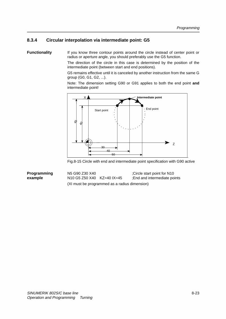
Programming
SINUMERIK 802S/C base line 8-23Operation and Programming Turning
8.3.4 Circular interpolation via intermediate point: G5
Functionality If you know three contour points around the circle instead of center point orradius or aperture angle, you should preferably use the G5 function.
The direction of the circle in this case is determined by the position of theintermediate point (between start and end positions).
G5 remains effective until it is canceled by another instruction from the same Ggroup (G0, G1, G2, ...).
Note: The dimension setting G90 or G91 applies to both the end point andintermediate point!
30Z
X
End pointStart point
5040
Intermediate point
4045
Fig.8-15 Circle with end and intermediate point specification with G90 active
Programming N5 G90 Z30 X40 ;Circle start point for N10example N10 G5 Z50 X40 KZ=40 IX=45 ;End and intermediate points
(XI must be programmed as a radius dimension)

Programming
8-24 SINUMERIK 802S/C base line Operation and Programming Turning
8.3.5 Thread cutting with constant lead: G33
Functionality Function G33 can be used to cut the following types of threads with constantlead:
z Thread on cylindrical bodies
z Thread on tapered bodies
z External/internal threads
z Single-start/multiple-start threads
z Multi-block threads (thread “chaining”)
This function requires a spindle with position measuring system.
G33 remains effective until it is canceled by another instruction from the sameG group (G0, G1, G2,G3,...).
external
internal
Fig.8-16 Example of external /internal thread on cylindrical body
RH or LH threads The direction of the thread, i.e. right-hand or left-hand, is determined by thesetting for the direction of rotation of the spindle (M3 - clockwise rotation, M4 -counterclockwise rotation; see Section 8.4 “Spindle Movements“). To this aim,the speed setting must be programmed under address S, or a speed must beset.
Note: The approach and run-out paths must be taken into account with respectto the thread length.
End point Start point Zero degree mark of spindle encoder
SF=...
Offset
Thread length
Lead
Lead: I or K(Value is constant over the entire thread length of a G33 block)
RH or LH thread (M3 / M4)
Further start point possible (for multiple-start threads)
Side view Top view
Fig.8-17 Programmable quantities for thread cutting with G33

Programming
SINUMERIK 802S/C base line 8-25Operation and Programming Turning
X
ZX
Z
X
Z
X
Z
Angle at taper is less than 45 degrees
Angle at taper is greater than 45 degrees
Lead:
Lead: K
Lead:
I
I
Programming:
G33 Z... K...
G33 Z... X... K...
G33 Z... X... I...
G33 X... I...
(Lead K, since Z axis has the longer path)
(Lead I, since X axis has the longer path)
Lead:
Cylindrical thread
Tapered thread
Transversal thread
K
Fig.8-18 Lead assignment on the example of Z/X axis
In the case of tapered threads (2 axes must be specified), the lead address I orK of the axis with the longer path (greater thread length) must be used. Asecond lead is not specified.
Start-point offset A start-point offset of the spindle is required for machining multiple-start threadsSF= or threads in offset cuts. The start-point offset is programmed under address
SF in the thread block with G33 (absolute position).
If a start point is not included in the block, the value from the setting data isactivated.
Note: Any value programmed for SF= is always entered in the setting data aswell.
Programming Cylindrical thread, two-start, start-point offset 180 degrees, thread length (includingexample approach and run-out) 100 mm, thread lead 4 mm/rev.,
RH thread, cylinder premachined:
N10 G54 G0 G90 X50 Z0 S500 M3 ;Approach start point, CW spindle rotationN20 G33 Z-100 K4 SF=0 ;Lead:4 mm/rev.N30 G0 X54N40 Z0N50 X50N60 G33 Z-100 K4 SF=180 ;2nd start, 180 degrees offsetN70 G0 X54 ...
Multi-block thread If several thread blocks are programmed in succession (multi-block thread), itmakes only sense to program a start-point offset in the 1st thread block sincethis is the only block in which the function is effective.
Multi-block threads are automatically linked by G64 (continuous path mode,see Section 8.3.9 ”Exact Stop/Continuous Path Control: G60, G64”).
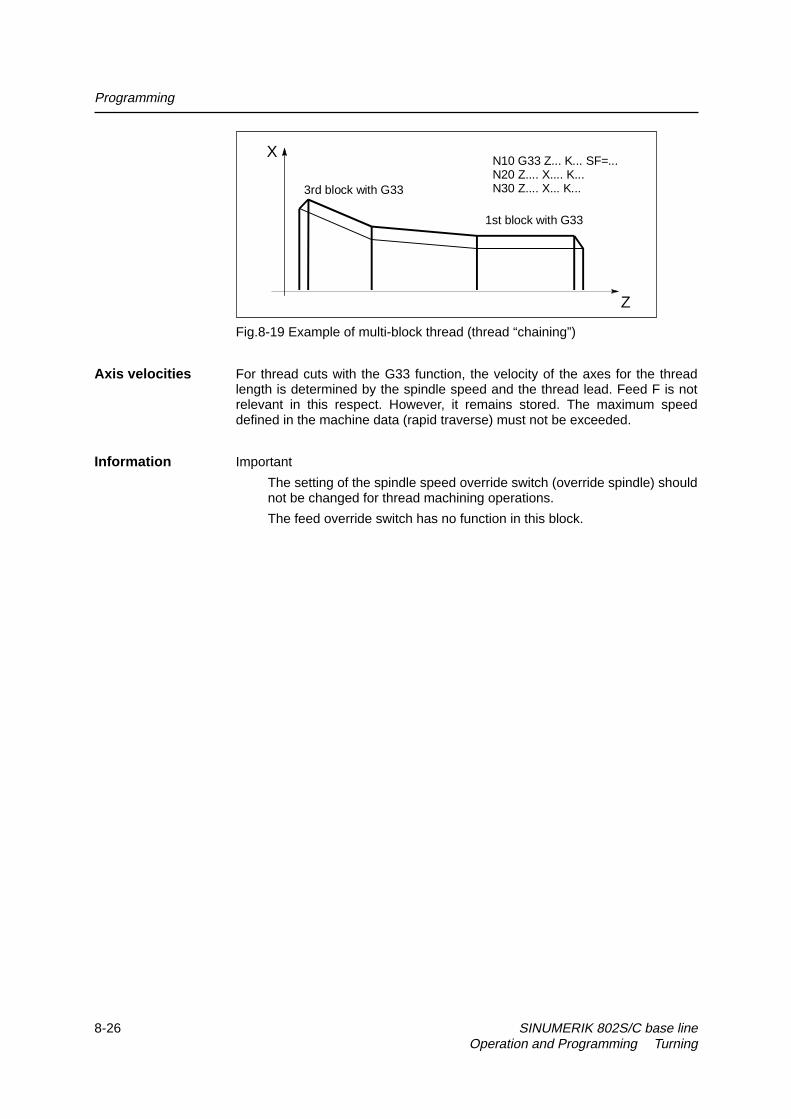
Programming
8-26 SINUMERIK 802S/C base line Operation and Programming Turning
3rd block with G33
1st block with G33
N10 G33 Z... K... SF=...N20 Z.... X.... K...N30 Z.... X... K...
X
Z
Fig.8-19 Example of multi-block thread (thread “chaining”)
Axis velocities For thread cuts with the G33 function, the velocity of the axes for the threadlength is determined by the spindle speed and the thread lead. Feed F is notrelevant in this respect. However, it remains stored. The maximum speeddefined in the machine data (rapid traverse) must not be exceeded.
Information Important
� The setting of the spindle speed override switch (override spindle) shouldnot be changed for thread machining operations.
� The feed override switch has no function in this block.

Programming
SINUMERIK 802S/C base line 8-27Operation and Programming Turning
8.3.6 Fixed-point approach: G75
Functionality G75 can be used to approach to a fixed point on the machine, such as the toolchange point. The position is fixed for all axes in the machine data. No offset isapplied.The speed of each axis is its own rapid traverse setting.G75 required a separate block and is non-modal.The G command from the Interpolation Type group (G0, G1,G2, ...) which wasactive prior to the block with G75 is activated after the block with G75.
Programming N10 G75 X0 Z0example Note: The programmed numerical values for X, Z are ignored.
8.3.7 Reference point approach: G74
Functionality G74 is used to execute the reference-point approach in the NC program.Direction and speed of each axis are stored in machine data.G74 requires a separate block and is non-modal. The G command for theInterpolation Type group (G0, G1,G2, ...) active prior to the block with G74 isactivated again after the block with G74.
Programming N10 G74 X0 Z0example Note: The programmed numerical values for X, Z are ignored.

Programming
8-28 SINUMERIK 802S/C base line Operation and Programming Turning
8.3.8 Feedrate F
Functionality The feedrate F is the path speed and represents the absolute value of thegeomnetric total of the speed components of all axes involved.
The axis speeds are determined by the axis path distance in relation to thetotal path distance.
The feedrate F is effective in interpolation modes G1, G2, G3 and G5 andremains active until a new F word is inserted in the program.
Programming F...
Note: Decimal points can be omitted in case of integer values, e.g. F300.
Unit for F–G94, G95 The unit of measurement for the F word is defined by G functions:
z G94 F as feedrate in mm/min
z G95 F as feedrate in mm/rev of spindle(only makes sense if spindle is in operation!)
Programming N10 G94 F310 ;Feedarte in mm/minexample ...
N110 S200 M3 ;Spindle operationN120 G95 F15.5 ;Feedrate in mm/rev
Note: Enter a new F word if you change from G94 to G95.
Information The group with G94 and G95 has additional functions G96 and G97 forconstant cutting rate for turning machines. These functions also influence the Sword (see Section 8.5.1 “Constant Cutting Rate“).

Programming
SINUMERIK 802S/C base line 8-29Operation and Programming Turning
8.3.9 Exact stop / continuous path mode: G9, G60, G64
Functionality These G functions enable you to set the traversing behavior at block limits andto control program advance to the next block, thus allowing you to adapt yourprogram optimally to various requirements. For example, you want to positionquickly with the axes or process path contours over several blocks.
Programming G60 ;Exact stop - (modal)G64 ;Continuous path mode
G9 ;Exact stop - (non-modal)
G601 ;Exact stop window fineG602 ;Exact stop window coarse
Exact stop G60, G9 If the exact stop function (G60 or G9) is active, the speed for reaching theexact target position is reduced towards zero at the end of the program block.
Another modally active G group can be set in conjunction with these functionsto determine the moment at which the traversing motion in this block is finishedso that processing of the next block can commence.
z G601 Exact stop window fineProcessing of the next block commences as soon as all axes havereached the “Exact stop window fine” (value in machine data).
z G602 Exact stop window coarseProcessing of the next block commences as soon as all axes havereached the “Exact stop window coarse” (value in machine data).
The selection of the exact stop window significantly affects the total machiningtime if many positioning operations need to be carried out. Fine adjustmentsrequire more time.
S
S
X
Z
G 6 01
G 6 02
(f ine)
(coa rse )A dvan ce to n e xt b lock fo r“co a rse ” and fo r “fin e ”
Fig.8-20 Coarse or fine exact stop window, effective with G60/G9, zoomedview of window

Programming
8-30 SINUMERIK 802S/C base line Operation and Programming Turning
Programming N5 G602 ;Exact stop coarseexample N10 G0 G60 Z... ;Exact stop modal
N20 X... Z... ;G60 still active...N50 G1 G601 ... ;Exact stop window fineN80 G64 Z... ;Switchover to continuous path...N100 G0 G9 Z... ;Exact stop acts only in this blockN111 ... ;Return to continuous path mode...
Note: The command G9 generates an exact stop only for the block in which it isprogrammed; in contrast, G60 remains active until it is canceled by G64.
Continuous path The purpose of continuous path mode is to prevent braking of the axes at blockmode G64 limits to make the transition to the next block at the most constant possible
speed (in the case of tangential transitions). The function operates withlookahead speed control to the next block. In the case of non-tangential pathtransitions (corners), the speed is reduced to such an extent in some casesthat none of the axes is capable of making a speed step change that is higherthan the maximum acceleration rate. In such cases, speed-dependentrounding at corners occurs.
S
X
Z
Advance to next block with feed F2
Advance to next block with feed F1
Feed F2 is greater than F1
Fig.8-21 Rounding at contour corners with G64
Programming N10 G64 G1 Z... F... ;Continuous path modeexample N20 X.. ;Continuous path control mode still active
...N180 G60 ... ;Switching to exact stop

Programming
SINUMERIK 802S/C base line 8-31Operation and Programming Turning
Fig.8-22 Comparison between speed responses with G60 and G64 with short block paths
8.3.10 Dwell time: G4
Functionality You can interrupt machining between two NC blocks for a defined time periodby inserting a separate block with G4, e.g. for relief cutting operations.The words with F... or S... are used for time specifcations only in this block. Anypreviously programmed feed F or spindle speed S remain unaffected.
Programming G4 F... ;Dwell time in secondsG4 S... ;Dwell time in spindle revolutions
Programming N5 G1 F200 Z-50 S300 M3 ;Feed F, spindle speed Sexample N10 G4 F2.5 ;Dwell time 2.5 s
N20 Z70N30 G4 S30 ;Dwell for 30 spindle revolutions, corresponds to t = 0.1 when S = 300 rev/min and 100% speed overrideN40 X... ;Feed and spindle speed values remain effective
Note G4 S.. can only be programmed if the machine has a controlled spindle (if thespeed has also been programmed under address S... ).
Programmed feed F
F1
N1
G60 - exact stop
N2 N3 N5 N6 N7 N8 N9 N10 N11 N12 Block path
Programmed speed cannot be reached because block paths too short
G64 - continuous path mode
N4

Programming
8-32 SINUMERIK 802S/C base line Operation and Programming Turning
8.4 Spindle movements
8.4.1 Spindle speed S, directions of rotation
Functionality The spindle speed is programmed under address S in revolutions per minute, ifthe machine has a controlled spindle. The direction of rotation and the start orend of the movement are specified by means of M commands (see Section“Miscellaneous Function M”).
Note: A decimal point may be omitted in the case of integer S values, e.g.S270.
Information If you insert M3 or M4 in a block with axis movements, then the M commandswill take effect before the axis movements.
Default setting: The axis movements will only start after the spindle has run up(M3, M4). M5 is also output prior to the axis movement. However, the axes willnot wait for the spindle being stopped. The axis movements will aleady startbefore the spindle has come to a standstill. The spindle is stopped withprogram end or RESET.
Note:Other settings can be configured via machine data.
Programming example N10 G1 X70 Z20 F300 S270 M3 ;Spindle powers up to 270 rev/min in clockwise
rotation before axis traversal X, Z...N80 S450 ... ;Speed change...N170 G0 Z180 M5 ;Z movement in block, spindle stop

Programming
SINUMERIK 802S/C base line 8-33Operation and Programming Turning
8.4.2 Spindle speed limitation: G25, G26
Functionality You can restrict the speed limit values that otherwise apply by programming aspeed limit value using G25 or G26 and spindle address S. These functionsalso overwrite the values entered in the setting data.
G25 or G26 each requires a separate block. Any previously programmedspeed S remains effective.
Programming G25 S... ;Lower spindle speed limitationG26 S... ;Upper spindle speed limitation
Information The maximum upper and lower spindle speed limits are set in a machine data.Setting data can be activated via the operator panel to limit the speed rangestill further.
The special function G96 (constant cutting rate) can be used to program anadditional upper limit on turning machines.
Programming N10 G25 S12 ;Lower spindle limit speed: 12 rev/minexample N20 G26 S700 ;Upper spindle limit speed: 700 rev/min

Programming
8-34 SINUMERIK 802S/C base line Operation and Programming Turning
8.4.3 Spindle positioning: SPOS
Functionality Precondition: The spindle must be technically designed for operation underclosed-loop position control.
The SPOS= function allows you to position the spindle in a specific angularposition. It is then held in this position by a closed-loop position controlfunction.
The speed of the positioning operation is defined in a machine data.
The applicable direction of rotation is maintained from the M3/M4 movementuntil the positioning process is complete. When the spindle is positioned fromstandstill, the position is approached via the shortest possible path. In this case,the direction is determined by the start and end positions.
Exception: Initial movement of spindle, i.e. if the measuring system is not yetsynchronized. In such cases, the direction is specified by a machine data.
The spindle movements are executed in parallel to any axis movements thatare programmed in the same block. Processing of the block is complete whenboth movements have been executed.
Programming SPOS=... ;Absolute position: 0 ... <360 Grad
Programming N10 SPOS=14.3 :Spindle position 14.3 degreesexample ...
N80 G0 X89 Z300 SPOS=25.6 ;Position spindle with axis movements. The block is complete once all movements
have been executed.N81 X200 Z300 ;N81 block does not start until spindle position from N80 is reached.

Programming
SINUMERIK 802S/C base line 8-35Operation and Programming Turning
8.5 Special turning functions
8.5.1 Constant cutting rate: G96, G97
Functionality Precondition: The machine must have a controlled spindle.
When the G96 function is active, the spindle speed is adjusted to the diameterof the workpiece currently being machined (facing axis) such that aprogrammed cutting rate S remains constant at the tool edge (spindle speedtimes diameter = constant).
The S word is interpreted as the cutting rate from the block with G96 onwards.G96 is active as a modal command until it is cancelled by another G function inthe same group (G94, G95, G97).
Programming G96 S... LIMS=... F... ;Constant cutting rate ONG97 ;Constant cutting rate OFF
STL ExplanationS Cutting rate, unit m/minLIMS= Upper limit speed of spindle, effective only with G96F Feed in mm/rev unit of measurement - as for G95
Note:
In this case, feed F is always interpreted in the unit of measurementmm/revolution.
If G94 was active instead of G95 beforehand, then a suitable F word must beinserted again in the program!
M WD 2 D 1
X (F ac ing axis )
D 1 x S D 1 = D 2 x S D 2= D n x S D n = con s ta n t
S D = S p in d le spe ed
D 1 , D 2 = D iam e te r
Fig.8-23 Constant cutting rate G96
Traversing at rapid No speed changes take place during rapid traversal with G0.traverse Exception: If the contour is approached in rapid traverse mode and the next
block contains an interpolation type G1 or G2, G3, G5 (contour block), then thespeed is adjusted to the value for the contour block while the approach blockwith G0 is being processed.

Programming
8-36 SINUMERIK 802S/C base line Operation and Programming Turning
Upper limit speed The spindle speed may rise sharply when large diameters are machined downLIMS= to small diameters. For such applications, it is advisable to specify the upper
spindle speed limitation by means of LIMS=... . LIMS is effective only inconjunction with G96.
When LIMS=... is programmed, the value entered in the setting data isoverwritten.
The upper speed limit programmed with G26 or via machine data cannot beoverwritten by the LIMS= function.
Deactivate constant The “Constant cutting rate” function is deactivated with G97. If G97 is active, acutting rate: G97 subsequently programmed S word is interpreted again as the spindle speed in
revolutions per minute.
If no further S word is inserted in the program, then the spindle continues torotate at the speed that was recorded when the G96 function was last active.
Programming N10 ... M3 ;Direction of rotation of spindleexample N20 G96 S120 LIMS=2500 ;Activate constant cutting rate, 120 m/min,
limit speed 2,500 rev/minN30 G0 X150 ;No speed change because block N31 includes G0N31 X50 Z... ;No speed change because block N32 includes
G0N32 X40 ;Approach contour, new speed is automatically
set to value required for start of block N40N40 G1 F0.2 X32 Z... ;Feed 0.2 mm/rev...N180 G97 X... Z... ;Deactivate constant cutting rateN190 S... ;New spindle speed, rev/min
Information The G96 function can also be deactivated by G94 or G95 (same G group). Inthis case, the last programmed spindle speed S applies for the remainder ofthe machining operation provided no new S word is programmed.
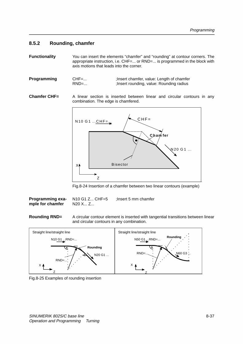
Programming
SINUMERIK 802S/C base line 8-37Operation and Programming Turning
8.5.2 Rounding, chamfer
Functionality You can insert the elements “chamfer” and “rounding” at contour corners. Theappropriate instruction, i.e. CHF=... or RND=... is programmed in the block withaxis motions that leads into the corner.
Programming CHF=... ;Insert chamfer, value: Length of chamferRND=... ;Insert rounding, value: Rounding radius
Chamfer CHF= A linear section is inserted between linear and circular contours in anycombination. The edge is chamfered.
B isec tor
C h am fer
X
Z
N 10 G 1 ...C H F =...
N 20 G 1 ...
C H F =
Fig.8-24 Insertion of a chamfer between two linear contours (example)
Programming exa- N10 G1 Z... CHF=5 ;Insert 5 mm chamfermple for chamfer N20 X... Z...
Rounding RND= A circular contour element is inserted with tangential transitions between linearand circular contours in any combination.
X
Z
RND=...
RoundingN50 G1 ...RND=...
N60 G3 ...
X
Z
RND=...
Rounding
N10 G1 ...RND=...
N20 G1 ...
Straight line/straight line Straight line/straight line
Fig.8-25 Examples of rounding insertion

Programming
8-38 SINUMERIK 802S/C base line Operation and Programming Turning
Programming exa- N10 G1 Z... RND=8 ;Insert rounding with 8 mm radiusmple for rounding N20 X... Z...
...N50 G1 Z... RND=7.3 ;Insert rounding with 7.3 mm radiusN60 G3 X... Z...
Information Note:
The programmed value for the chamfer or rounding is automatically reducedwhen the contour programmed in one of the blocks involved is not sufficientlylong.
No chamfer/rounding is inserted if more than one of the subsequentlyprogrammed blocks does not contain any information about traversal of theaxes.
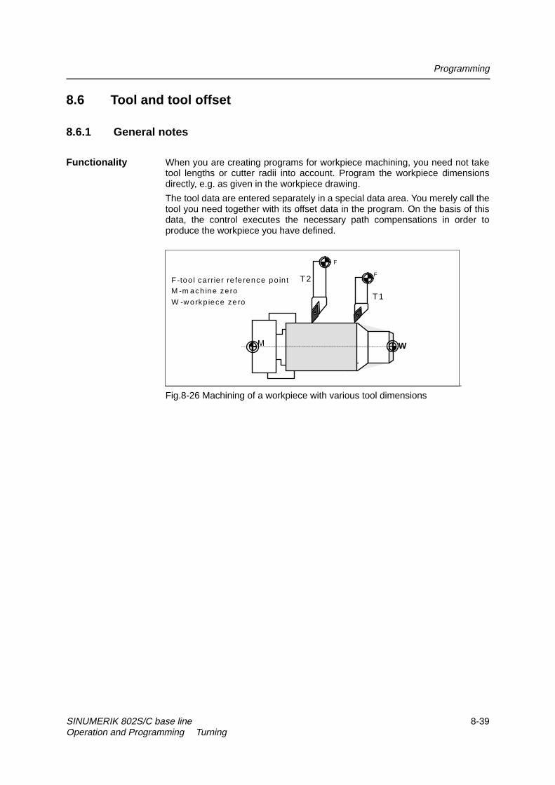
Programming
SINUMERIK 802S/C base line 8-39Operation and Programming Turning
8.6 Tool and tool offset
8.6.1 General notes
Functionality When you are creating programs for workpiece machining, you need not taketool lengths or cutter radii into account. Program the workpiece dimensionsdirectly, e.g. as given in the workpiece drawing.
The tool data are entered separately in a special data area. You merely call thetool you need together with its offset data in the program. On the basis of thisdata, the control executes the necessary path compensations in order toproduce the workpiece you have defined.
W
F
FF -too l ca rrie r re fe rence po in t
M
M -m ach ine ze ro
W -w orkp iece ze ro
T2
T1
Fig.8-26 Machining of a workpiece with various tool dimensions

Programming
8-40 SINUMERIK 802S/C base line Operation and Programming Turning
8.6.2 Tool T
Functionality You select a tool by programming the T word. A machine data defines whetherthe T word represents a tool change or merely a preselection.
z Tool change (tool call) is implemented directly by T word (e.g. normalpractice for tool revolver on turning machines) or
z the tool is changed through additional instruction M6 after preselection byT word (see also Section “Miscellaneous Functions M”).
Please note:If a certain tool has been activated, this will remain stored as the active tooleven across the program end and after POWER ON of the control system.
If you change a tool manually, then enter the change into the control systemalso manually to make sure that the control system detects the right tool. Forexample, you can start a block with a new T word in the MDA mode.
Programming T... ;Tool number: 1 ... 32 000
Note
A maximum of 15 tools can be stored in the control at a time.
Programming Tool change without M6:example N10 T1 ;Tool 1
...N70 T588 ;Tool 588

Programming
SINUMERIK 802S/C base line 8-41Operation and Programming Turning
8.6.3 Tool offset number D
Functionality You can assign between 1 and 9 data fields with various tool offset blocks (forseveral tool edges) to each specific tool. If a special edge is required, it can beprogrammed by means of D plus a corresponding number.
D1 is the automatic default if no D word is programmed.When D0 is programmed, then the offsets for the tool are not active.
Note
A maximum of 30 data fields with tool offset blocks can be stored in the controlat a time.
Programming D... ;Tool offset number: 1 ... 9 D0: No offsets active
Fig.8-27 Example assignment of tool offset numbers to tool
Information Tool length compensations take immediate effect when the tool is active. Thevalues of D1 are applied if no D number has been programmed. The toollength is compensated when the first programmed traversal of the relevantlength compensation axis is executed.
A tool radius compensation must also be activated by means of G41/G42.
Programming Tool change:example N10 T1 ;Tool 1 is activated with associated D1
N11 G0 X... Z... ;The length compensation is superimposed hereN50 T4 D2 ;Change to tool 4, D2 of T4 becomes active...N70 G0 Z... D1 ;D1 for tool 4 is active, only edge changed
Contents of an Enter the following in the offset memory:offset memory
z Geometric quantities: Length, radiusThese consist of several components (geometry, wear). The controlcomputes the component data to produce a resultant quantity (e.g. totallength 1, total radius). The total dimension calculated in each case takeseffect when the offset memory is activated.
T1
T2
T3
T6
T...
D1
D1
D1
D1
D1
D2 D3 D9
D2
D2 D3
T9 D1 D2

Programming
8-42 SINUMERIK 802S/C base line Operation and Programming Turning
The method used to compute these values in the axes depends on the tooltype and commands G17, G18 (see diagrams below).
z Tool type
The tool type determines which geometry data are necessary and how they arecomputed (drills or turning tools). The hundreds place is the only distinguishingdigit:
� Type 2xy: Drills
� Type 5xy: Turning tools
z Tool point direction
You must also specify the tool point direction for tool type 5sy (turning tools).
Tool parameters The value for the relevant tool parameters is entered next to DP... . The tooltype determines which parameters are required. Any tool parameters notneeded must be set to “0”.
Tool type: DP1Edge length: DP2
Geometry WearLength 1: DP3 DP12Length 2: DP4 DP13Radius: DP6 DP15
The following diagrams show which tool parameters are needed for which tooltype.
Fig.8-28 Length compensation values required for turning tools
G18:
Length 2Tool tip P(Z)(tool nose)
Effect
Length 1 in XLength 2 in Z
Length 1(X)
Turning tool
Z
X
Set all othervalues to 0
DP1
DP3
5xy
Length 1
Entries in toolparameters
DP4
Wear values acc.to requirements
Length 2
F - Tool carrier reference point
F

Programming
SINUMERIK 802S/C base line 8-43Operation and Programming Turning
X
Set all othervalues to 0
DP1
DP3
5xy
Length 1
Entries in toolparameters
DP4
Wear values acc. torequirements
Effect
G18: Length 1 in XLength 2 in Z
Length 2
DP1
DP3
5xy
Length 1
DP4 Length 2
D1
D2
Grooving tool
Length 2(edge 2 =D2)Tool tip P
D1:
D2 :
F -
Length 2
D1: Length 1(X )
Tool tip P(edge 1 =D1)
Tool carrierreference point
D2: Length 1(X )
(Z)
(Z )
Fig.8-29 Turning tool with length compensation for two edges

Programming
8-44 SINUMERIK 802S/C base line Operation and Programming Turning
Length 1
Length 2
Tool tipP
(X)
(Z)
(tool nose)
P
R -Edge radius (tool radius)
S -Position of tool nose center point
Turning tool
Z
X
The tool parameter DP2 specifies the tool point direction. Direction value 1 to 9 can be programmed:
Z
X
Z
X
P=S
1 2 3 4 5 6
7 8 9
Tool point direction DP2:
Note:Parameters length 1 and length 2 refer topoint P with tool point directions1..8, but to S (S=P) with 9.
P
Effect
G18: Length 1 in XLength 2 in Z
Set all othervalues to 0
DP1 5xx
Length1
Entries in toolparameters
DP4
Wear valuesacc. torequirements
Length 2
DP2 1...9
DP6Radius
F - Tool carrier reference point
F
S S
S S
S
S
S
S
S
DP3
Fig.8-30 Offset data required for turning tools with tool radius compensation

Programming
SINUMERIK 802S/C base line 8-45Operation and Programming Turning
Set all othervalues to 0
F - Tool carrier reference point
DP1
Entries in toolparameters
DP3
2xy
Length 1
Effect
G17: Length 1 in Z
G18:
Wear values acc.to requirements
Length 1
F
Turning tools
Fig.8-31 Offset data required for drills
Centre hole To drill a center hole, switch over to G17. The length compensation then actson the drill in the Z axis. After drilling, switch back to G18 for the normal turningtool offset.
Example:N10 T... ;Drill, =tool type 200N20 G17 G1 F... Z... ;Length compensation acts in Z axisN30 Z...N40 G18 .... ;Drilling completed
M F
Z
X
Fig.8-32 Drilling a center hole

Programming
8-46 SINUMERIK 802S/C base line Operation and Programming Turning
8.6.4 Selection of tool radius compensation: G41, G42
Functionality A tool with a corresponding D number must be active. The tool radiuscompensation (tool nose radius compensation) is activated by G41/G42. Thecontrol then automatically calculates the necessary tool paths equidistant fromthe programmed contour for the current tool radius.
G18 must be active.
M
Tool nose radius
Fig.8-33 Tool (nose) radius compensation
Programming G41 X... Z... ;Tool radius compensation to left of contourG42 X... Z... ;Tool radius compensation to right of contour
Note: You may only select the function for linear interpolation (G0, G1).Program both axes. If you only specify one axis, then the last programmedvalue is automatically set for the second axis.
G42
G41
Fig. 8-34 Compensation to right/left of contour
Begin compen- The tool approaches the contour on a linear path and positions itself perpendicularsation to the path tangent at the start of the contour. Select the start point such that
the tool can traverse safely with no risk of collision.

Programming
SINUMERIK 802S/C base line 8-47Operation and Programming Turning
S
S
S
R
P1
Compensated tool path
P0 -Start point
First contour section: Straight line
P1 -First contour section: CircleR -Tool nose radius
First contour section: Circle
G42
MP
Circle radius
S
P1
Compensated tool path
Tangent
P0 -Start point
G42
R
Fig.8-35 Beginning of tool radius compensation –example shows G42, tool point direction =3
Information The block containing G41/G42 is generally followed by the first block with theworkpiece contour. The contour definition may, however, be interrupted by anintermediate block that does not contain any contour information, e.g. by ablock with just an M command.
Programming N10 T... F...example N15 X... Z... ;P0 start point
N20 G1 G42 X... Z... ;Select compensation to the right of the contour, P1N30 X... Z... ;Initial contour section, circle or straight line

Programming
8-48 SINUMERIK 802S/C base line Operation and Programming Turning
8.6.5 Behavior at corners: G450, G451
Functionality Functions G450 and G451 are provided to allow you to set the response in thecase of discontinuous transition from one contour element to another (behaviorat corners) when G41/G42 is active.
The control itself detects inside and outside corners. The point at which theequidistant paths intersect is always approached in the case of inside corners.
Programming G450 ;Transition circleG451 ;Intersection
S
Transition circle (radius = tool radius)
IntersectionOutside corner Outside corner G450 G451
S
Fig.8-36 Behavior at an outside corner
Inside corner Intersection
S S
Fig 8-37 Behavior at an inside corner
Transition circle The tool center point traverses round the workpiece outer corner along an arcG450 with the same radius as the tool radius.
In processing terms, the transition circle belongs to the next block that containstraversing movements, e.g. relating to feed value.
Intersection G451 With function G451 (intersection of equidistant paths), the tool approaches thepoint at which the center point paths (circle or straight line) intersect.

Programming
SINUMERIK 802S/C base line 8-49Operation and Programming Turning
8.6.6 Tool radius compensation OFF: G40
Functionality Function G40 is used to canceled compensation mode G41/G42. This Gfunction is also preset for program start.
The tool ends the block before G40 in normal position (i.e. compensationvector perpendicular to tangent at end point), independently of retraction angle.Always select the end point of the G40 block such that the tool can traversesafely with no risk of collision.
Programming G40 X... Z... ;Tool radius compensation OFF
Note: Tool radius compensation can be canceled only in linear interpolationmode (G0, G1).
Program both axes. If you only specify one axis, then the last programmedvalue is automatically set for the second axis.
R
P1
Final contour section: Straight line
R - Tool nose radius
Final contour section: Circle
G40
P1Tangent
S
P2 - End point, block with G40
P2
P1 - End point, last block with e.g. G42
S
P2
MP
Circle radiusR
G40
Fig.3-38 Cancelation of tool radius compensation using G40, example showsG42, tool point direction=3
Programming ...example N100 X... Z... ;Last block on contour, circle or straight line, P1
N110 G40 G1 X... Z... ;Deactivate tool radius compensation, P2

Programming
8-50 SINUMERIK 802S/C base line Operation and Programming Turning
8.6.7 Special cases of tool radius compensation
Change in compen- The compensation direction G41 <-> can be changed without inserting a G40sation direction instruction in-between.
The last block with the old compensation direction ends with the compensationvector in the normal position at the end point. The new compensation directionis executed as start of compensation (position at start point).
Repetition of G41, The same contour can be programmed again without inserting a G40 instructionG41 or G42, G42 beforehand.
The last block before the new compensation call ends with the compensationvector in the normal position at the end point. The repeat compensationprocess is executed as described under “Begin compensation” on page 8–142.
Change in offset The offset number D can be changed in compensation mode. In this case, annumber D altered tool radius becomes effective at the beginning of the block in which the
new D number is programmed. The full change in radius is not achieved untilthe end of the block, i.e. the change is implemented continuously over theentire block. This also applies to circular interpolation.
Cancellation of If compensation mode is aborted by means of M2 (program end) without a prog-com pensation rammed G40 instruction, then the last block ends with coordinates correspond-using M2 ing to the compensation vector in normal position. No compensatory movement
is executed. The program ends with this tool position.
Critical machining When programming machining operations, watch out for cases where the contouroperations path at inner corners is smaller than the tool radius and, with two consecutive
inner corners, smaller than the diameter.
This type of programming error must be avoided!
Check sequences of several blocks to make sure that the contour does notcontain any “bottlenecks”.
When you carry out a test/dry run, use the largest available tool radius.
B
Programmed contour
R
B < R
Collision
R - Tool nose radiusB - Contour path
Remedy: Switch from G450 to G451 in this case
S
S
Fig.3-39 Critical maching operation, example shows transition circle

Programming
SINUMERIK 802S/C base line 8-51Operation and Programming Turning
8.6.8 Example of tool radius compensation
S
S
W
Z
X
S
S
45˘
R55
R30
R20
5203084020
S
S
S
Fig.8-40 Example of tool radius compensation, tool nose radius magnified
Programming N1 ; ;Contour sectionexample N2 T1 ;Tool 1 with offset D1
N10 G22 F... S... M... ;Radius dimension specification, technological valuesN15 G54 G0 G90 X100 Z15N20 X0 Z6N30 G1 G42 G451 X0 Z0 ;Begin compensation modeN40 G91 X20 CHF=(5* 1.41) ;Insert chamferN50 Z-25N60 X10 Z-30N70 Z-8N80 G3 X20 Z-20 CR=20N90 G1 Z-20N95 X5N100 Z-25N110 G40 G0 G90 X100 ;End compensation modeN120 M2

Programming
8-52 SINUMERIK 802S/C base line Operation and Programming Turning
8.7 Miscellaneous function M
Functionality Miscellaneous function M can be used, for example, to initiate switchingoperations such as “Coolant ON/OFF”, among other tasks.
The control system manufacturer preassigns certain functions to a smallnumber of the M functions. The others can be freely assigned to functions bythe user.
A block may contain a maximum of 5 M functions.
Note
You will find an overview of all M functions reserved and used in the controlsystem in Section 8.1.5. “List of instructions“
Programming M...
Activation Activation in blocks with axis movements:If functions M0, M1 and M2 are programmed in a block that includes axismovements, then they take effect after the traversing movements have beenexecuted.
Functions M3, M4 and M5 are transferred to the internal interface controlbefore the traversing movements. The axis movements are not executed untilthe spindle has run up in M3 or M4. In the case of M5, however, the axismovements commence before the spindle has reached a standstill.
All the other M functions are transferred to the internal interface control at thesame time as the traversing movements.
If you wish to program an M function specifically before or after an axismovement, then insert a separate block with the M function.
Remember: This block will interrupt G64 continuous path mode and generatean exact stop!
Programming N10 S...example N20 X... M3 ;M function in block with axis movement Spindle runs
up before X axis movementN180 M78 M67 M10 M12 M37
;Max. 5 M functions in block

Programming
SINUMERIK 802S/C base line 8-53Operation and Programming Turning
8.8 Arithmetic parameters R
Functionality If you want an NC program in which you can vary the values to be processed,or if you simply needed to compute arithmetic values, then you can use R(arithmetic) parameters. The control system will calculate or set the values youneed when the program is executed.
An alternative method is to input the arithmetic parameter values directly. If theR parameters already have value settings, then they can be assigned in theprogram to other NC addresses that have variable values.
Programming R0=...toR249=...(to R299=..., if there are no machining cycles)
Explanation 250 arithmetic parameters with the following classification are available:
R0 ... R99 - for free assignment
R100 ... R249 - transfer parameters for machining cycles.
R250 ... R299 - internal arithmetic parameters for machining cycles.
If you do not intend to use machining cycles (see Section NO TAG “MachiningCycles”), then this range of arithmetic parameters is also available for youruse.
Value assignment You can assign values in the following range to the R parameters:
± (0.000 0001 ... 9999 9999)(8 decimal places and sign and decimal point).
The decimal point can be omitted for integer values. A positive sign can also beomitted.
Example:R0=3.5678 R1=-37.3 R2=2 R3=-7 R4=-45678.1234
You can assign an extended numerical range using exponential notation:
± ( 10-300 ... 10+300 ).
The value of the exponent is typed after the characters EX. Maximum numberof characters: 10 (including sign and decimal point).Value range of EX: -300 to +300.
Example:R0=-0.1EX-5 ;Meaning: R0 = -0,000 001R1=1.874EX8 ;Meaning: R1 = 187 400 000
Note: Several assignments (including arithmetic expressions) can beprogrammed in one block.
Assignment to You can obtain a flexible NC program by assigning arithmetic parameters orother addresses arithmetic expressions with R parameters to other NC addresses. Values,
arithmetic expressions or R parameters can be assigned to any NC addresswith the exception of addresses N, G and L.

Programming
8-54 SINUMERIK 802S/C base line Operation and Programming Turning
When making assignments of this kind, type the character “=” after the addresscharacter. Assignments with a negative sign are also permitted.
If you wish to make assignments to axis addresses (traversal instructions),then you must do so in a separate program block.
Example:N10 G0 X=R2 ;Assignment to X axis
Arithmetic opera- Operators/arithmetic functions must be programmed using the normal mathe-tions / functions matical notation. Processing priorities are set by means of round brackets. Otherwise the “multiplication/division before addition/subtraction” rule applies.
Degrees are specified for trigonometric functions.
Programming N10 R1= R1+1 ;The new R1 is product of old R1 plus 1example: R N20 R1=R2+R3 R4=R5-R6 R7=R8* R9 R10=R11/R12parameter N30 R13=SIN(25.3) ;R13 is the sine of 25.3 degrees
N40 R14=R1*R2+R3 ;“Multiplication/division before addition/subtraction” rule R14=(R1*R2)+R3
N50 R14=R3+R2*R1 ;Result as for block N40N60 R15=SQRT(R1*R1+R2*R2)
;Meaning: R15= R12 +R22
Programming N10 G1 G91 X=R1 Z=R2 F300example: Assi- N20 Z=R3gnment to axes N30 X=-R4
N40 Z=-R5...

Programming
SINUMERIK 802S/C base line 8-55Operation and Programming Turning
8.9 Program branches
8.9.1 Labels - destination for program branches
Functionality Labels are used to mark blocks as the branch destination for branches in theprogram sequence.
Labels can be selected freely, but must have a minimum of 2 and a maximumof 8 letters or digits. However the first two characters must be letters orunderscore characters.
Labels end in a colon in the block that is to act as a branch destination. Theyare always positioned at the beginning of the block. If the block also has ablock number, then the label is positioned after the number.
Labels must be unique within the same program.
Programming N10 MARKE1: G1 X20 ;MARKE1 is label, branch destinationexample ...
TR789: G0 X10 Z20 ;TR789 is label, branch destination No block number
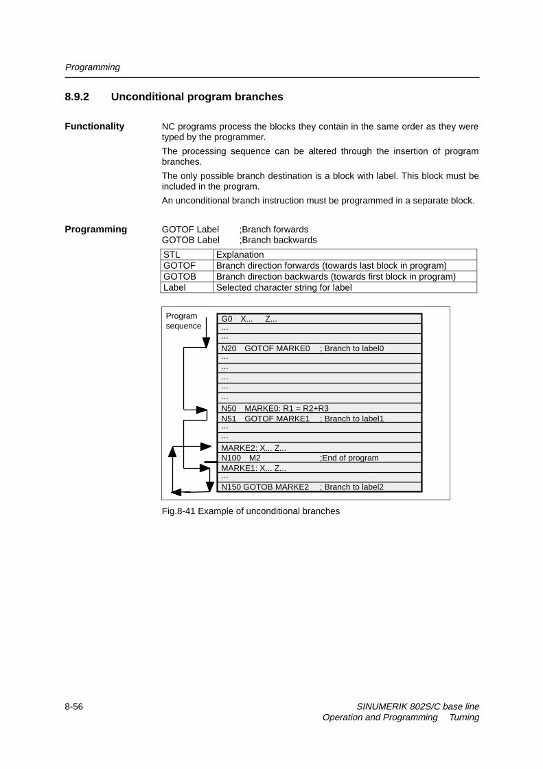
Programming
8-56 SINUMERIK 802S/C base line Operation and Programming Turning
8.9.2 Unconditional program branches
Functionality NC programs process the blocks they contain in the same order as they weretyped by the programmer.
The processing sequence can be altered through the insertion of programbranches.
The only possible branch destination is a block with label. This block must beincluded in the program.
An unconditional branch instruction must be programmed in a separate block.
Programming GOTOF Label ;Branch forwardsGOTOB Label ;Branch backwards
STL ExplanationGOTOF Branch direction forwards (towards last block in program)GOTOB Branch direction backwards (towards first block in program)Label Selected character string for label
Fig.8-41 Example of unconditional branches
Programsequence ...
...
N20 GOTOF MARKE0 ; Branch to label0...............
N50 MARKE0: R1 = R2+R3N51 GOTOF MARKE1 ; Branch to label1......
G0 X... Z...
...
MARKE2: X... Z...N100 M2 ;End of programMARKE1: X... Z...
N150 GOTOB MARKE2 ; Branch to label2

Programming
SINUMERIK 802S/C base line 8-57Operation and Programming Turning
8.9.3 Conditional branches
Functionality Branch conditions are formulated after the IF instruction. If the branch conditionis fulfilled (value not equal to zero), then the program branches. The branchdestination can only be a block with corresponding label. This block must becontained within the program.
Conditional branch instructions must be programmed in a separate block.Several conditional branch instructions can be programmed in the same block.
You can reduce program processing times significantly by using conditionalprogram branches.
Programming IF condition GOTOF Label ;Branch forwardsIF condition GOTOB Label ;Branch backwards
STL ExplanationGOTOF Branch direction forwards (towards last block in program)GOTOB Branch direction backwards (towards first block in program)Label Selected character string for labelIF Introduction of branch conditionCondition Arithmetic parameter, arithmetic expression in comparison for
formulation of condition
Comparison operations
Operators Meaning= = Equal to< > Not equal to > Greater than < Less than > = Greater than or equal to< = Less than or equal to
The comparison operations are used to formulate branch conditions. Arithmeticexpressions can also be compared.
The result of comparison operations is either “fulfilled” or “not fulfilled”. “Notfulfilled” is equivalent to a value of zero.
Programming R1>1 ;R1 greater than 1example for 1 < R1 ;1 less than R1comparison R1<R2+R3 ;R1 less than R2 plus R3operators R6>=SIN( R7*R7) ;R6 greater than or equal to SIN (R7)2
Programming N10 IF R1 GOTOF MARKE1 ;If R1 is not zero, branch to block withexample MARKE1
...N100 IF R1>1 GOTOF MARKE2 ;If R1 is greater than 1, branch to block with
MARKE2...

Programming
8-58 SINUMERIK 802S/C base line Operation and Programming Turning
N1000 IF R45==R7+1 GOTOB MARKE3;If R45 is equal to R7 plus 1, branch to block
with MARKE3...Several conditional branches in block:...N20 IF R1==1 GOTOB MA1 IF R1==2 GOTOF MA2 ......
Note: The program branches at the first fulfilled condition.
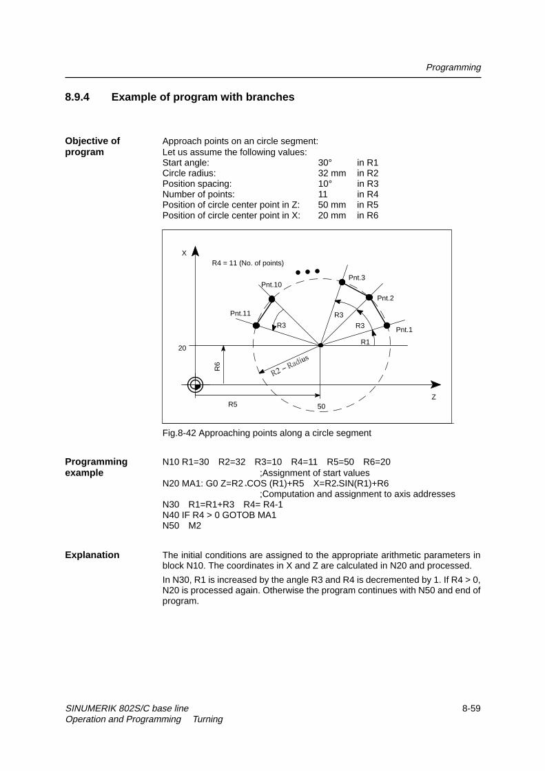
Programming
SINUMERIK 802S/C base line 8-59Operation and Programming Turning
8.9.4 Example of program with branches
Objective of Approach points on an circle segment:program Let us assume the following values:
Start angle: 30° in R1Circle radius: 32 mm in R2Position spacing: 10° in R3Number of points: 11 in R4Position of circle center point in Z: 50 mm in R5Position of circle center point in X: 20 mm in R6
R3
R5
20
50
R4 = 11 (No. of points)X
Z
Pnt.1
R1
Pnt.2
Pnt.11 R3
Pnt.10
R3
Pnt.3
R6
Fig.8-42 Approaching points along a circle segment
Programming N10 R1=30 R2=32 R3=10 R4=11 R5=50 R6=20example ;Assignment of start values
N20 MA1: G0 Z=R2 *COS (R1)+R5 X=R2*SIN(R1)+R6;Computation and assignment to axis addresses
N30 R1=R1+R3 R4= R4-1N40 IF R4 > 0 GOTOB MA1N50 M2
Explanation The initial conditions are assigned to the appropriate arithmetic parameters inblock N10. The coordinates in X and Z are calculated in N20 and processed.
In N30, R1 is increased by the angle R3 and R4 is decremented by 1. If R4 > 0,N20 is processed again. Otherwise the program continues with N50 and end ofprogram.

Programming
8-60 SINUMERIK 802S/C base line Operation and Programming Turning
8.10 Subroutine technique
Application There is no essential difference between a main program and a subroutine.
Subroutines contain frequently recurring machining sequences, for example,certain contour shapes. This type of subroutine is called at the appropriatelocations in the main program and then processed.
One type of subroutine is the machining cycle. Machining cycles containgenerally applicable machining operations (e.g. thread cutting, stock removal,etc.). By supplying these cycles with values by means of the arithmeticparameters provided, you can adapt the program to your specific application(see Section “Machining Cycles”).
Structure Subroutines are structured in exactly the same way as main programs (seeSection “Program structure”). M2 (end of program) is programmed in the lastblock of the subroutine sequence in exactly the same way as for mainprograms. In this case, program end means a return to the program level thatcalled the subroutine.
Program end The M2 end–of–program instruction can be substituted by the end instructionRET in subroutines.
RET must be programmed in a separate block.
An RET instruction must be used when it is necessary to avoid an interruptionin continuous path mode G64 when the program branches back to mainprogram level from the subroutine. If an M2 instruction is programmed, G64mode is interrupted and an exact stop generated.
M2
M2
N20 X...Z...
N10 R1=34 ...
L10
N20 L10 ;Call
N80 L10 ;Call
N21 ...
Main program
Subroutine
Return
Return
MAIN123
...
...
...
...
...
...
...
...
...
...
...
Sequence
Fig. 8-43 Example of program sequence in which subroutine is called twice
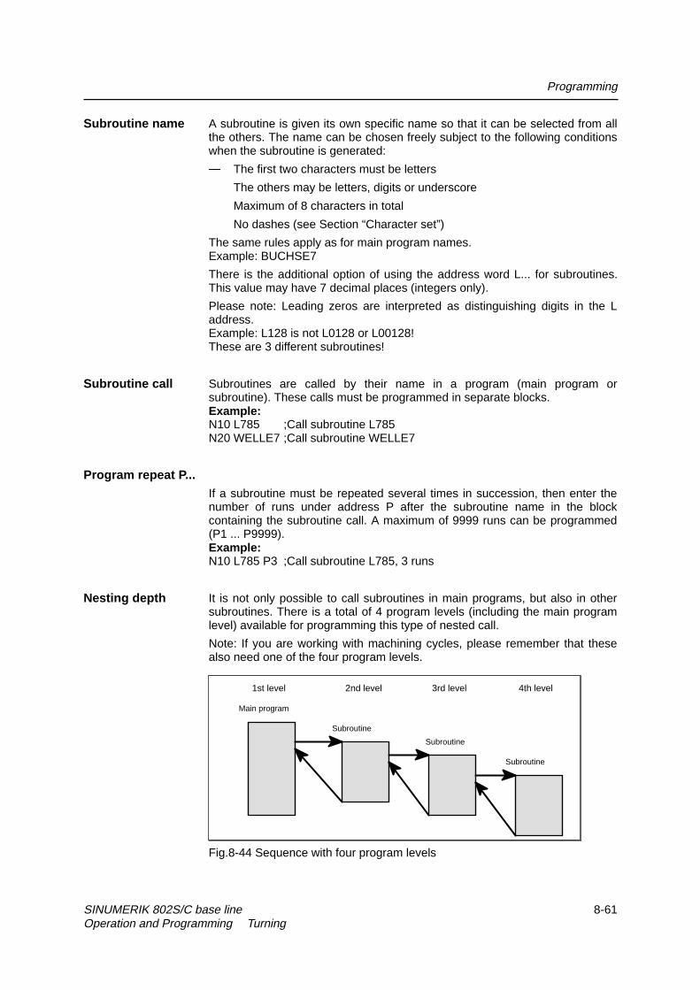
Programming
SINUMERIK 802S/C base line 8-61Operation and Programming Turning
Subroutine name A subroutine is given its own specific name so that it can be selected from allthe others. The name can be chosen freely subject to the following conditionswhen the subroutine is generated:
� The first two characters must be letters
� The others may be letters, digits or underscore
� Maximum of 8 characters in total
� No dashes (see Section “Character set”)
The same rules apply as for main program names.Example: BUCHSE7
There is the additional option of using the address word L... for subroutines.This value may have 7 decimal places (integers only).
Please note: Leading zeros are interpreted as distinguishing digits in the Laddress.Example: L128 is not L0128 or L00128!These are 3 different subroutines!
Subroutine call Subroutines are called by their name in a program (main program orsubroutine). These calls must be programmed in separate blocks.Example:N10 L785 ;Call subroutine L785N20 WELLE7 ;Call subroutine WELLE7
Program repeat P... If a subroutine must be repeated several times in succession, then enter the
number of runs under address P after the subroutine name in the blockcontaining the subroutine call. A maximum of 9999 runs can be programmed(P1 ... P9999).Example:N10 L785 P3 ;Call subroutine L785, 3 runs
Nesting depth It is not only possible to call subroutines in main programs, but also in othersubroutines. There is a total of 4 program levels (including the main programlevel) available for programming this type of nested call.
Note: If you are working with machining cycles, please remember that thesealso need one of the four program levels.
1st level 2nd level 3rd level 4th level
Main program
Subroutine
Subroutine
Subroutine
Fig.8-44 Sequence with four program levels

Programming
8-62 SINUMERIK 802S/C base line Operation and Programming Turning
Information It is possible to change modal G functions, e.g. G90 -> G91, in subroutines.Make sure that all modal functions are set in the way you require when theprogram branches back to the level on which the subroutine was called.
The same applies to the arithmetic (R) parameters. Make sure that thearithmetic parameters you are using in the upper program levels do not changeto different settings in lower levels.

SINUMERIK 802S/C base line 9-1Operation and Programming Turning
Cycles 9
Preface Cycles are process-related subroutines that support general implementation ofspecific machining processes such as, for example, drilling, stock removal orthread cutting. The cycles are adapted to the specific problem in hand bymeans of supply parameters.
Standard cycles for turning applications are provided in the system.
9.1 General Information about Standard Cycles
This section provides general programming notes for SIEMENS standardcycles.
9.1.1 Overview of Cycles
LCYC82 Drilling, spot-facingLCYC83 Deep hole drillingLCYC840 Tapping with compensation chuckLCYC85 BoringLCYC93 RecessLCYC94 Undercut (forms E and F to DIN)LCYC95 Stock removal with relief cutsLCYC97 Thread cutting
Supply parameters The arithmetic parameters in the R100 to R249 range are used as supplyparameters for cycles.
Before a cycle is called, values must be assigned to its transfer parameters.These value settings are unchanged after the cycle has been executed.
Arithmetic If you intend to use machining cycles, you must ensure that arithmetic parametersparameters R100 to R249 are reserved for this purpose, and are not used for other
functions within the program. The cycles use R250 to R299 as internalarithmetic parameters.

Cycles
9-2 SINUMERIK 802S/C base line Operation and Programming Turning
Call and return G23 (for LCYC93, 94, 95, 97) or G17 (for LCYC82, 83, 840, 85) (diameterconditions programming) must be active before a cycle is called. Otherwise, the error
message 17040 illegal axis index is output. The appropriate values for feedrate,spindle speed and spindle direction of rotation must be programmed in the partprogram if there are no supply parameters for these quantities in the cycle.
G0 G90 G40 are always effective at the end of a cycle.
9.1.2 Error messages and error handling in cycles
Error handling Alarms with numbers between 61000 and 62999 are generated in the cycles.in cycles In turn, this number range is subdivided into alarm reactions and reset criteria.
Table 9–1 Alarm numbers, reset criteria, alarm reactions
Alarm number Reaction Programcontinued by
61000...61999 Block preparation in the NC is aborted NC RESET62000...62999 Block preparation is interrupted, can be
continued with NC start after alarm resetReset key
The error text that is displayed at the same time as the alarm number providesfurther details about the cause of the error.
Overview of The following Table gives an overview of errors that can occur in cycles, thecycle alarms location of their origin and guidance on how to eliminate them.

Cycles
SINUMERIK 802S/C base line 9-3Operation and Programming Turning
Table 9–2 Cycle alarms
AlarmNumber Alarm Text Source (Cycle) Remedial Action
61001 Thread lead incorrectlydefined
LCYC840 Check parameter R106 (R106=0).
61002 “Machining type incorrectlyprogrammed”
LCYC93, 95, 97 The value of parameter R105 for themachining type is incorrectly set andmust be altered.
61003 3rd geometry axis missing LCYC82, 83,840
Check machine configuration and planeselection (connect 3rd geometry axis).
61101 Reference plane incorrectlydefined
LCYC82, 83,840, 85
Check parameters R101, R103, R104 -R103 = R104, or R103 is not betweenR101 and R104.
61102 No spindle direction defined LCYC840 Value in parameter R107 is greater than4 or less than 3.
61107 “First drilling depth incorrectlydefined”
LCYC83 Change the value for 1st drilling depth(first drilling depth is in opposition to totaldrilling depth)
61601 “Finished part diameter toosmall”
LCYC94 A finished part diameter of < 3mm isprogrammed. This setting is illegal.
61602 “Tool width incorrectlydefined”
LCYC93 The tool width (parameter R107) doesnot match the programmed recess type.
61603 “Recess form incorrectlydefined”
LCYC93 The recess form is incorrectlyprogrammed.
61606 “Error when preparing thecontour”
LCYC95 Check contour subroutine.Check machining type parameter (R105)
61608 “Incorrect tool point directionprogrammed”
LCYC94 A tool point direction 1 ... 4 that matchesthe undercut form must be programmed.
61609 “Form incorrectly defined” LCYC94 Check parameters for undercut form.61610 “No infeed depth
programmed”LCYC95 The parameter for infeed depth R108
must be set >0 for roughing.

Cycles
9-4 SINUMERIK 802S/C base line Operation and Programming Turning
9.2 Drilling, counter boring – LCYC82
Function The tool drills with the spindle speed and feedrate programmed down to theentered final depth. When the final drilling depth is reached, a dwell time canbe programmed. The drill is retracted from the drill hole at rapid traverse rate.
Call LCYC82
Fig.9-1 Motional sequence and parameters in the cycle
Precondition The spindle speed and the direction of rotation, as well as the feed of thedrilling axis must be defined in the higher-level program.
The drilling position must be approached before calling the cycle in the higher-level program.
The required tool with tool offset must be selected before calling the cycle.
G17 must be active.
Parameters
Parameter Meaning, Value RangeR101 Retract plane (absolute)R102 Safety clearanceR103 Reference plane (absolute)R104 Final drilling depth (absolute)R105 Dwell time in seconds
Information
R101 The retract plane determines the position of the drilling axis at the end of thecycle.
R102 The safety clearance acts on the reference plane, i.e. the reference plane isshifted forward by an amount corresponding to the safety clearance.
The direction in which the safety clearance acts is automatically determined bythe cycle.
G1
G4
R101
R103+R102R103
R104X
Z

Cycles
SINUMERIK 802S/C base line 9-5Operation and Programming Turning
R103 The starting point of the drill hole shown in the drawing is programmed underthe reference plane parameter.
R104 The drilling depth is always programmed as an absolute value with refer toworkpiece zero.
R105 The dwell time at drilling depth (chip breakage) is programmed in secondsunder R105.
Motional sequence Position reached prior to beginning of cycle:last position in the higher-level program (drilling position)
The cycle produces the following motional sequence:
1. Approach reference plane shifted forward by an amount corresponding tothe safety clearance using G0.
2. Traverse to final drilling depth with G1 and the feedrate programmed inthe higher-level program.
3. Execute dwell time to final drilling depth.
4. Retract to retract plane with G0.
Example Drilling - counter boring
The program produces a 27 mm deep drill hole in the position X24 Y15 in theXY plane using the cycle LCYC82. The dwell time is 2 s, and the safetyclearance in the drilling axis (here: Z) amounts to 4 mm. On completion of thecycle, the tool stands on X24 Y15 Z110.
Fig.9-2 Example drawing
N10 G0 G17 G90 F500 T2 D1 S500 M4 ; Define technology values
N20 X24 Y15 ; Approach drilling position
N25 G17
N30 R101=110 R102=4 R103=102 R104=75 ; Supply parameters
N35 R105=2 ; Supply parameters
N40 LCYC82 ; Call cycle
N50 M2 ; End of program
102
Z
X

Cycles
9-6 SINUMERIK 802S/C base line Operation and Programming Turning
9.3 Deep hole drilling – LCYC83
Function The deep-hole drilling cycle produces center holes down to the final drillingdepth by repeated, step-by-step deep infeed whose maximum amount can beparameterized. The drill can be retracted either to the reference plane for swarfremoval after each infeed depth or by 1 mm in each case for chip breakage.
Call LCYC83
R 1 01
2n d dr ill ing dep th
1s t d r il ling d ep th R 11 0
G 1
G 0
etc .
G 4
C learanc e d is tanc e
N o te In th e d iag ram , th e c le a ranc e d is tanc e to th e c u rren t d ri llin g d ep th is s
th e 1s t d r ill in g d ep th . In rea lity , it is ef fec t ive f or e very d ri lling d ep th .
R 1 04
N e xt d rillin gdep th
G 0
G 1
G 0
G 0
. ..
G 4
G 4
T h is m o tio nalsequenc e isrepea ted fo r eachd r ill ing dep th
c u rren t d ril l. d ep th
R 1 03 + R 1 02R 1 03
Fig.9-3 Motional sequence and parameters in the cycle
Precondition The spindle speed and the direction of rotation must be defined in the higher-level program.
The drilling position must be approached before calling the cycle in the higher-level program.
Before calling the cycle, a tool offset for the drill must be selected.
G17 must be active.

Cycles
SINUMERIK 802S/C base line 9-7Operation and Programming Turning
Parameters
Parameter Meaning, Value RangeR101 Retract plane (absolute)R102 Safety clearance, enter without signR103 Reference plane (absolute)R104 Final drilling depth (absolute)R105 Dwell time to drilling depth (chip breakage)R107 Feed for drillingR108 Feed for first drilling depthR109 Dwell time at starting point and for swarf removalR110 First drilling depth (absolute)R111 Absolute degression, enter without signR127 Machining type:
Chip breakage = 0Swarf removal = 1
Information
R101 The retract plane determines the position of the drilling axis at the end of thecycle.
The cycle is programmed on the assumption that the retract plane positioned infront of the reference plane, i.e. its distance to the final depth is greater.
R102 The safety clearance acts on the reference plane, i.e. the reference plane isshifted forward by an amount corresponding to the safety clearance.
The direction in which the safety clearance acts is automatically determined bythe cycle.
R103 The starting point of the drill hole shown in the drawing is programmed underthe reference plane parameter.
R104 The drilling depth is always programmed as an absolute value regardless ofhow G90/91 is set prior to cycle call.
R105 The dwell time at drilling depth (chip breakage) is programmed in secondsunder R105.
R107, R108 The feed for the first drilling stroke (under R108) and for all subsequent drillingstrokes (under R107) are programmed via the parameters.
R109 A dwell time at the starting point can be programmed in seconds underparameter R109.
The dwell time at the starting point is executed only for the “with swarf removal”variant.
R110 Parameter R110 determines the depth of the first drilling stroke.

Cycles
9-8 SINUMERIK 802S/C base line Operation and Programming Turning
R111 Parameter R111 for the absolute degression value determines the amount bywhich the current drilling depth is reduced with subsequent drilling strokes.
The second drilling depth corresponds to the stroke of the first drilling depthminus the absolute degression value provided that this value is greater thanthe programmed absolute degression value.
Otherwise, the second drilling depth also corresponds to the absolutedegression value.
The next drilling strokes correspond to the absolute degression value providedthat the remaining degression depth is still greater than twice the absolutedegression value. The remainder is then distributed evenly between the lasttwo drilling strokes.
If the value for the first drilling depth is in opposition to the total drilling depth,the error message
61107 ”First drilling depth incorrectly defined“is displayed, and the cycle is not executed.
R127 Value 0:The drill travels 1 mm clear for chip breakage after it has reached each drillingdepth.
Value 1:The drill travels to the reference plane, which is shifted forward by an amountcorresponding to the safety clearance for swarf removal after each drillingdepth.
Motional sequence Position reached prior to beginning of cycle:last position in the higher-level program (drilling position)
The cycle produces the following motional sequence:
1. Approach reference plane shifted forward by an amount corresponding tothe safety clearance using G0.
2. Traverse to first drilling depth with G1; the feedrate results from thefeedrate programmed prior to cycle call after it has been computed withthe setting in parameter R109 (feedrate factor).Execute dwell time at drilling depth (parameter R105).
With chip breakage selected:
Retract by 1 mm from the current drilling depth with G1 for chip breakage.
With swarf removal selected:
Retract for swarf removal to reference plane shifted forward by anamount corresponding to the safety clearance with G0 for swarf removal,executing the dwell time at starting point (parameter R106), approach lastdrilling depth minus clearance distance calculated in the cycle using G0.
3. Traverse to next drilling depth with G1 and the programmed feed; thismotional sequence is continued as long as the final drilling depth isreached.
4. Retract to retract plane with G0.

Cycles
SINUMERIK 802S/C base line 9-9Operation and Programming Turning
Example: Deep-hole drilling
Fig. 9-4 Example drawing
;This program executes the cycle LCYC83 at position X0.
N100 G0 G18 G90 T4 S500 M3 ;Define technology values
N110 Z155
N120 X0 ;Approach first drilling position
N125 G17
R101=155 R102=1 R103=150
R104=5 R105=0 R109=0 R110=100 ;Parameter assignment
R111=20 R107=500 R127=1 R108=400
N140 LCYC83 ;1st call of cycle
N199 M2

Cycles
9-10 SINUMERIK 802S/C base line Operation and Programming Turning
9.4 Tapping with compensating chuck – LCYC840
Function The tool drills with the programmed spindle speed and direction of rotationdown to the entered thread depth. The feed of the drilling axis results from thespindle speed. This cycle can be used for tapping with compensating chuckand spindle actual-value encoder. The direction of rotation is automaticallyreversed in the cycle. The retract can be carried out at a separate speed. M5acts after the cycle has been executed (spindle stop).
Call LCYC840
Fig.9-5
Precondition This cycle can only be used with a speed-controlled spindle with positionencoder. The cycle does not check whether the actual-value encoder for thespindle really exists.
The spindle speed and the direction of rotation must be defined in the higher-level program.
The drilling position must be approached before calling the cycle in the higher-level program.
The required tool with tool offset must be selected before calling the cycle.
G17 must be active.
Parameters
Parameter Meaning, Value RangeR101 Retract plane (absolute)R102 Safety clearanceR103 Reference plane (absolute)R104 Final drilling depth (absolute)R106 Thread lead as value
value range: 0.001 .... 2000.000 mmR126 Direction of rotation of spindle for tapping
Value range: 3 (for M3), 4 (for M4)
G0
G33
G33
R101
R103R103+R102
R104
Z
X

Cycles
SINUMERIK 802S/C base line 9-11Operation and Programming Turning
Information
R101 -R104 See LCYC84
R106 Thread lead as value
R126 The tapping block is executed with the direction of rotation of spindleprogrammed under R126. The direction of rotation is automatically reversed inthe cycle.
Motional sequence Position reached prior to beginning of cycle:- last position in the higher-level program (drilling position)
The cycle produces the following motional sequence:
1. Approach reference plane shifted forward by an amount corresponding tothe safety clearance using G0
2. Tapping down to final drilling depth with G33
3. Retract to reference plane shifted forward by an amount corresponding tothe safety clearance with G33
4. Retract to retract plane with G0
Example This program is used for tapping on the position X0; the Z axis is the drillingaxis. The parameter for the direction of rotation R126 must be parameterized.A compensating chuck must be used for machining. The spindle speed isdefined in the higher-level program.
5615
Z
X
Fig.9-6 Example drawing
N10 G0 G17 G90 S300 M3 D1 T1 ; Define technology values
N20 X35 Y35 Z60 ; Approach drilling position
G17
N30 R101=60 R102=2 R103=56 R104=15 ; Parameter assignment
N40 R106=0.5 R126=3 ; Parameter assignment
N40 LCYC840 ; Cycle call
N50 M2 ; End of program

Cycles
9-12 SINUMERIK 802S/C base line Operation and Programming Turning
9.5 Boring – LCYC85
Function The tool drills with the spindle speed and feedrate programmed down to theentered final drilling depth. When the final drilling depth is reached, a dwell timecan be programmed. The approach and retract movements are carried out withthe feedrates programmed under the respective parameters.
Call LCYC85
Fig.9-7 Motional sequence and parameters of the cycle
Precondition The spindle speed and the direction of rotation must be defined in the higher-level program.
The drilling position must be approached before calling the cycle in the higher-level program.
Before calling the cycle, the respective tool with tool offset must be selected.
Parameters
Parameter Meaning, Value RangeR101 Retract plane (absolute)R102 Safety clearanceR103 Reference plane (absolute)R104 Final drilling depth (absolute)R105 Dwell time at drilling depth in secondsR107 Feed for drillingR108 Feed when retracting from drill hole
Information
Parameters R101 - R105 see LCYC82
R107 The feed value defined here acts for drilling.
R108 The feed value entered under R108 acts for retracting from the drill hole.
R104
G0
G1
G4
R101
R103+R102R103
Z

Cycles
SINUMERIK 802S/C base line 9-13Operation and Programming Turning
Motional sequence Position reached prior to beginning of cycle:last position in the higher-level program (drilling position)
The cycle produces the following motional sequence:
1. Approach reference plane shifted forward by an amount corresponding tothe safety clearance using G0
2. Traverse to final drilling depth with G1 and the feed programmed underparameter R106.
3. Execute dwell time at final drilling depth.
4. Retract to reference plane shifted forward by an amount corresponding tothe safety clearance with G1 and the retract feed programmed underR108.
Example The cycle LCYC85 is called in Z70 and X50 in the ZX plane. The Y axis is thedrilling axis. No dwell time is programmed. The workpiece upper edge is atY=102.
10277
Z
X
Fig.9-8 Example drawing
N10 G0 G90 G18 F1000 S500 M3 T1 D1 ; Define technology values
N20 Z70 X50 Y105 ; Approach drilling position
N30 R101=105 R102=2 R103=102 R104=77 ; Define parameters
N35 R105=0 R107=200 R108=400 ; Define parameters
N40 LCYC85 ; Call drilling cycle
N50 M2 ; End of program

Cycles
9-14 SINUMERIK 802S/C base line Operation and Programming Turning
9.6 Recess cycle – LCYC93
Fuction The recess cycle is designed to produce symmetrical recesses for longitudinaland face machining on cylindrical contour elements. The cycle is suitable formachining internal and external recesses.
Call LCYC93
R101
R108
R116
R114 R118
R116 R115R100
R117
X
Z
Fig.9-9 Parameters in the recess cycle in longitudinal machining
Precondition The recess cycle can only be called if G23 (diameter programming) is active.The tool offset of the tool whose tool nose width has been programmed withR107 must be activated before the recess cycle is called. The zero position ofthe tool nose faces machine zero.
Parameters Table 9–3 Parameters for LCYC93 cycle
Parameter Meaning, Value RangeR100 Starting point in facing axisR101 Starting point in longitudinal axisR105 Machining method,
Value range 1 ... 8R106 Finishing allowance, without signR107 Tool nose width, without signR108 Infeed depth , without signR114 Recess width, without signR115 Recess width, without signR116 Flank angle, without sign,
between 0 <= R116 < = 89.999 degreesR117 Chamfer on rim of recessR118 Chamfer on recess baseR119 Dwell time on recess base
Information
R100 The recess diameter in X is specified in parameter R100.

Cycles
SINUMERIK 802S/C base line 9-15Operation and Programming Turning
R101 R101 determines the point at which the recess starts in the Z axis.
R105 R105 defines the recess variant:
Table 9–4 Recess variants
Value Longitudinal/Facing External/Internal Starting Point Position1 L A Left2 P A Left3 L I Left4 P I Left5 L A Right6 P A Right7 L I Right8 P I Right
If the parameter is set to any other value, the cycle is aborted with the alarm
61002 “Machining type incorrectly programmed”.
R106 Parameter R106 determines the finishing allowance for roughing of the recess.
R107 Parameter R107 determines the tool nose width of the recessing tool. Thisvalue must correspond to the width of the tool actually used.
If the tool nose of the active tool is wider, the contour of the programmedrecess will be violated. Such violations are not monitored by the cycle.
If the programmed tool nose width is wider than the recess width at the base,the cycle is aborted with the alarm
G1602 “Tool width incorrectly defined”.
R108 By programming an infeed depth in R108, it is possible to divide the axis-parallel recessing process into several infeed depths. After each infeed, thetool is retracted by 1 mm for chip breakage.
Recess form Parameters R114 ... R118 determine the form of the recess. The cycle alwaysbases its calculation on the point programmed under R100, R101.
R114 The recess width programmed in parameter R114 is measured on the base.The chamfers are not included in the measurement.
R115 Parameter R115 determines the depth of the recess.
R116 The value of parameter R116 determines the angle of the flanks of the recess.When it is set to “0”, a recess with axis-parallel flanks (i.e. rectangular form) ismachined.
R117 R117 defines the chamfers on the recess rim.
R118 R118 defines the chamfers on the recess base.

Cycles
9-16 SINUMERIK 802S/C base line Operation and Programming Turning
If the values programmed for chamfers do not produce a meaningful recesscontour, then the cycle is aborted with the alarm
61603 “Recess form incorrectly defined”.
R119 The dwell time on the recess base to be entered in R119 must be selectedsuch that at least one spindle revolution can take place during the dwell period.It is programmed to comply with an F word (in seconds).
Motional Sequence Position reached prior to beginning of the cycle:
z Any position from which each recess can be approached without risk ofcollision.
The cycle produces the following motional sequence:
z Approach with G0 starting point cacluated internally in the cycle.
z Execute depth infeeds:Roughing in parallel axes down to base, taking finishing allowance intoaccount. Tool travels clear for chip breakage after each infeed.
z Execute width infeeds:Width infeeds are executed perpendicular to the depth infeed with G0,the roughing process for machining the depth is repeated.
The infeeds both for depth and width are distributed evenly with the highestpossible value.
z Rough the flanks. Infeed along the recess width is executed in severalsteps if necessary.
z Finish-machine the whole contour, starting at both rims and workingtowards center of recess base, at the feedrate programmed before thecycle call.
Example
X
Z
Chamfers 2mm
Starting point (60, 35)R108=10
20°20°
30
25 mm
Fig.9-10 Example diagram
;A recess is machined that starts at point (60.35) 25 mm in depth
;and 30 mm in width.
;Two chamfers of 2 mm in length are programmed on the base.
;The finishing allowance is 1 mm.

Cycles
SINUMERIK 802S/C base line 9-17Operation and Programming Turning
N10 G0 G90 Z100 X100 T2 D1 S300 M3 G23 ;Select start position
N20 G95 F0.3 ;and technology values
R100=35 R101=60 R105=5 R106=1 R107=12 ;Parameters for cycle call
R108=10 R114=30 R115=25 R116=20
R117=0 R118-2 R119=1
N60 LCYC93 ;Call recess cycle
N70 G90 G0 Z100 X50 ;Next position
N100 M2
Note on example The tool offset of the recessing tool must be stored in D1 of tool T2. The toolnose width must be 12 mm.

Cycles
9-18 SINUMERIK 802S/C base line Operation and Programming Turning
9.7 Undercut cycle – LCYC94
Function This cycle machines undercuts of forms E and F in compliance with DIN 509for normal stressing on finished part diameters > 3 mm.
A tool offset must be activated before the cycle is called.
Call LCYC94
FORM EFORM F
X
Z
For workpieces with one machining surface
For workpieces with two mutually perpendicular machining surfaces
X
Z
R101
R100
Fig.9-11 Undercut forms E and F
Condition G23 (diameter programming) must be active for this cycle.
Parameters Table 9–5 Parameters for LCYC94 cycle
Parameter Meaning, Value RangeR100 Starting point in facing axis, without signR101 Starting point in longitudinal axisR105 Definition of form:
Value 55 for form EValue 56 for form F
R107 Definition of tool point direction:Values 1...4 for directions 1...4
Information
R100 The finished part diameter for the undercut is specified in parameter R100.
If the value programmed for R100 corresponds to a final diameter of <= 3 mm,then the cycle is aborted with the alarm
61601 “Finished part diameter too small”.
R101 R101 determines the finished part dimension in the longitudinal axis.
R105 Forms E and F are defined in DIN509 and must be selected using one of theseparameters.

Cycles
SINUMERIK 802S/C base line 9-19Operation and Programming Turning
If parameter R105 is set to a value other than 55 or 56, then the cycle isaborted and generates the alarm
61609 “Form incorrectly defined”.
R107 This parameter defines the tool point direction and thus the undercut position.The value set here must correspond to the actual point direction of the toolselected prior to cycle call.
SL 3
Tool nose radius
Theoretical nose tip
P
SL 4
SL 2SL 1
+X
+Z
Fig.9-12 Tool point directions 1…4
If the parameter is set to any other value, the alarm
61608 “Incorrect tool point direction programmed” is output and the cycle isaborted.
Motional sequence Position reached prior to beginning of cycle:
z Any position from which undercut can be approached without risk ofcollission.
The cycle produces the following motional sequence:
z Approach with G0 starting point calculated internally in the cycle.
z Select tool nose radius compensation in accordance with active tool nosedirection and traverse undercut contour at feedrate programmed prior tocycle call.
z Return to starting point with G0 and deselect tool nose radiuscompensation with G40.
Example ;This program machines an undercut of form E.
N50 G0 G90 G23 Z100 X50 T25 D3 S300 M3 ;Select starting position
N55 G95 F0.3 ;and enter technology valuesR100=20 R101=60 R105=55 R107=3 ;Parameters for cycle call
N60 LCYC94 ;Call undercut for cycle
N70 G90 G0 Z100 X50 ;Next position
N99 M02

Cycles
9-20 SINUMERIK 802S/C base line Operation and Programming Turning
9.8 Stock removal cycle – LCYC95
Function This cycle can machine a contour, which is programmed in a subroutine, in alongitudinal or face machining process, externally or internally, through axis-parallel stock removal.
The technology (roughing/finishing/complete machining) can be selected. Thecycle can be called from any chosen collision-free position.
A tool offset must have been activated in the program with the cycle call.
Call LCYC95
Contour shifted by finishing allowance
X
Z
1
23
45
Original contour
Infeed
1 Infeed2 Roughing3 Cut residual corners 4 Lift5 Return
Fig.9-13 Motional sequence with LCYC 95 cycle
Condition
z The cycle requires an active G23 (diameter programming).
z The file SGUD.DEF, which is supplied on the cycles diskette, must beavailable in the control system.
z The stock removal cycle can be called to the 3rd program level.
Parameters Table 9–6 Parameters for the LCYC95 cycle
Parameter Meaning, Value RangeR105 Machining type,
value range 1 ... 12R106 Finishing allowance, without signR108 Infeed depth, without signR109 Infeed angle for roughing, it should be zero at face
machining.R110 Contour clearance distance for roughingR111 Feedrate for roughingR112 Feedrate for finishing

Cycles
SINUMERIK 802S/C base line 9-21Operation and Programming Turning
Information
R105 The machining types:
z longitudinal/facing
z internal/external
z roughing/finishing/complete machining
are defined by the parameter determining the type of machining.
When longitudinal machining is selected, the infeed always takes place in thefacing axis, and vice versa.
Table 9–7 Variants of stock removal
Value Longitudinal/Facing(P)
External/Internal(A/I)
Roughing/Finishing/Complete Machining
1 L A Roughing2 P A Roughing3 L I Roughing4 P I Roughing5 L A Finishing6 P A Finishing7 L I Finishing8 P I Finishing9 L A Complete
10 P A Complete11 L I Complete12 P I Complete
If any other value is programmed for the parameter, the cycle is aborted andthe following alarm output
61002 “Machining type incorrectly programmed”.
R106 A finishing allowance can be programmed in parameter R106.
The workpiece is always rough-machined down to this finishing allowance. Inthis case, the residual corner produced in the course of each axis-parallelroughing process is immediately cut away in parallel with the contour at thesame time. If no finishing allowance is programmed, the workpiece is rough-machined right down to the final contour.
R108 The maximum possible infeed depth for the roughing process is entered underparameter R108. However, the cycle itself calculates the current infeed depththat is applied in rough-machining operations.
R109 The infeed motion for roughing can be executed at an angle which can beprogrammed in parameter R109. In the face machining process a slantingimmerse is not possible, R109 must be programmed to ZERO.
R110 Parameter R110 specifies the distance by which the tool is lifted from thecontour in both axes after each roughing operation so that it can be retractedby G0.

Cycles
9-22 SINUMERIK 802S/C base line Operation and Programming Turning
R111 The feedrate programmed under R111 applies to all paths on which stock isremoved during roughing operations.
If finishing is the only machining type selected, then this parameter has nomeaning at all.
R112 The feedrate programmed under R112 is applied for finishing operations. Ifroughing is the only machining type selected, then this parameter has nomeaning at all.
Contour definition The contour to be machined by stock removal is programmed in a subroutine.The name of the subroutine is transferred to the cycle via the _CNAMEvariable.
The contour may consist of straight lines and circle segments; radii andchamfers can be inserted. The programmed circle sections can be quartercircles as a maximum.
Undercuts may not be contained in the contour. If an undercut element isdetected, the cycle is aborted, and the alarm
61605 “Contour incorrectly defined” is output.
The contour must always be programmed in the direction that is traversedwhen finishing according to the selected machining direction.
Example of contour programming
P8(35,120)
P0 = programmed starting point of contourP8 = programmed end point
P0(100,40)
X
Z
P1(85,40)
P2(85,54)
P3(77,70)
P4(67,70)
P5(62,80)
P6(62,96)
P7(50,120)
Fig.9-14 Example of contour programming
With the coordinates given in the program, the contour must be programmedfor longitudinal external machining as follows:
N10 G1 Z100 X40 ;Starting point
N20 Z85 ;P1
N30 X54 ;P2
N40 Z77 X70 ;P3

Cycles
SINUMERIK 802S/C base line 9-23Operation and Programming Turning
N50 Z67 ;P4
N60 G2 Z62 X80 CR=5 ;P5
N70 G1 Z62 X96 ;P6
N80 G3 Z50 X120 CR=12 ;P7
N90 G1 Z35 ;P8
M17
For external facing, the contour must be programmed starting at P8 (35,120)and finishing at P0 (100,40).
Motional sequence Position reached prior to beginning of cycle:
z Any position from which the contour starting point can be approachedwithout risk of collision.
The cycle produces the following motional sequence
Roughingz Approach cycle starting point (calculated internally) with G0 in both axes
simultaneously.
z Perform depth infeed with the angle programmed under R109 to the nextroughing depth.
z Approach roughing cut point in parallel axes with G1 and at a feedrateprogrammed in R111.
z Travel in parallel with contour along contour + finishing allowance up tothe last roughing cut point with G1/G2/G3 and at feedrate R111.
z Lift in each axis by the clearance (in mm) programmed in R110 andretract with G0.
z Repeat this sequence until the final roughing depth is reached.
Finishingz Approach the cycle starting point in individual axes with G0
z Approach the contour starting point in both axes simultaneously with G0.
z Finish-machine along the contour with G1/G2/G3 and at the feedrateprogrammed in R112.
z Retract to cycle starting point in both axes with G0.
When finishing is selected, the tool radius compensation is automaticallyactivated internally in the cycle.
Starting point The cycle automatically calculates the point at which machining must start.The starting point is always approached in both axes simultaneously forroughing and in individual axes for finishing. In this case, the infeed axisapproaches the starting point first.
When complete machining is selected, the tool does not return to the internallycalculated starting point after the last roughing cut

Cycles
9-24 SINUMERIK 802S/C base line Operation and Programming Turning
Example The cycle requires the following two programs:
z program with cycle call
z contour subroutine (TESTK1.MPF)
;The contour shown in the example must be machined externally;in a complete machining operation in the longitudinal axis.;The maximum infeed is 5 mm, the finishing allowance is 1.2 mm,;and the infeed angle is 7 degrees.
N10 T1 D1 G0 G23 G95 S500 M3 F0.4 ;Definition of technology valuesN20 Z125 X162 ;Collision-free approach position prior to the call
_CNAME= “TESTK1” ;Name of contour subroutine
R105=9 R106=1.2 R108=5 R109=7 ;Set further parameters forR110=1.5 R111=0.4 R112=0.25 ;cycle callN20 LCYC95 ;Cycle callN30 G0 G90 X81 ;Re-approach starting positionN35 Z125 ;Approach in individual axesN99 M30
Subroutine “TESTK1”N10 G1 Z100 X40 ;Starting pointN20 Z85 ;P1N30 X54 ;P2N40 Z77 X70 ;P3N50 Z67 ;P4N60 G2 Z62 X80 CR=5 ;P5N70 G1 Z62 X96 ;P6N80 G3 Z50 X120 CR=12 ;P7N90 G1 Z35 ;P8
M2

Cycles
SINUMERIK 802S/C base line 9-25Operation and Programming Turning
9.9 Thread cutting – LCYC97
Function The thread cutting cycle is suitable for cutting external and internal, single-startor multiple-start threads on cylindrical and tapered bodies in the facing orlongitudinal axis. Depth infeed is an automatic function.
Whether a right-hand or left-hand thread is produced is determined by thedirection of rotation of the spindle, which must be programmed before callingthe cycle. Feed and spindle override are not effective in the traversing blockscontaining thread cutting operations.
Call LCYC97
Fig.9-15 Schematic diagram of parameters for thread cutting
Parameters Table 9–8 Parameters for LCYC97 cycle
Parameter Meaning, Value RangeR100 Diameter of thread at starting pointR101 Thread starting point in longitudinal axisR102 Diameter at end pointR103 Thread end point in longitudinal axisR104 Thread lead as value, without signR105 Definition of thread cutting method:
Value range: 1, 2R106 Finishing allowance, without signR109 Approach path, without signR110 Run-out path, without signR111 Thread depth, without signR112 Starting point offset, without signR113 Number of rough cuts, without signR114 Number of threads, without sign
Z
R103 R101
R109R110
R111 R100 = R102
External thread cutting
Effect of parameters for lead,infeed angle and finishingallowance
R104R106

Cycles
9-26 SINUMERIK 802S/C base line Operation and Programming Turning
Information
R100, R101 These parameters define the thread starting point in X and Z.
R102, R103 The thread end point is programmed under R102 and R103. In the case ofcylindrical threads, one of these parameters has the same value as R100 orR101.
R104 The thread lead is an axis-parallel value and is specified without sign.
R105 Parameter R105 defines whether the thread is machined internally orexternally.
R105 = 1: External thread
R105 = 2: Internal thread
If the parameter is set to any other value, the cycle is aborted with the alarm
61002 “Machining type incorrectly programmed”.
R106 The programmed finishing allowance is subtracted from the specified threaddepth. The remainder is divided into rough cuts.
The finishing allowance is removed in one cut after roughing.
R109, R110 Parameters R109 and R110 specifiy the internally calculated thread approachand run-out paths. The cycle shifts the programmed starting point forward bythe approach distance. The run-out path extends the length of the threadbeyond the programmed end point.
R111 Parameter R111 defines the total depth of the thread.
R112 An angle value can be programmed in this parameter. This value defines thepoint at which the first thread cut starts on the circumference of the turned part,i.e. it is a starting point offset.
Possible values for this parameter are between 0.0001 ... + 359.9999 degrees.
If no starting point offset is specified, the first thread automatically starts at thezero-degree marking.
R113 Parameter R113 determines the number of roughing cuts for thread cuttingoperations. The cycle independently calculates the individual, current infeeddepths as a function of the settings in R105 and R111.
R114 This parameter specifies the number of threads. These are arrangedsymmetrically around the circumference of the turned part.
Longitudinal or The cycle itself decides whether a thread must be machined in the longitudinalface thread or facing axis. If the angle on the taper is less than or equal to 45 degrees, then
the thread is machined as a longitudinal thread, otherwise as a face thread.

Cycles
SINUMERIK 802S/C base line 9-27Operation and Programming Turning
Motional sequence Position reached prior to beginning of cycle:
z Any position from which the programmed thread starting point +approach path can be approached without risk of collision.
The cycle produces the following motional sequence:
z Approach starting point at the beginning of the approach path (calculatedinternally in the cycle) to cut first thread with G0.
z Infeed for rough cutting according to the infeed method defined underR105.
z Repeat thread cuts according to the programmed number of rough cuts.
z Remove the finishing allowance with G33.
z Repeat the whole sequence for every further thread.
Example
X
Z
35
M42×2
Fig.9-16 Example diagram
;A two-start thread, M42x2, must be machined.
N10 G23 G95 F0.3 G90 T1 D1 S1000 M4 ;Define technology values
N20 G0 Z100 X120 ;Program start position
R100=42 R101=80 R102=42 R103=45 ;Parameters for cycle call
R105=1 R106=1 R109=12 R110=6
R111=4 R112=0 R113=3 R114=2
N50 LCYC97 ;Cycle call
N100 G0 Z100 X60 ;Position after cycle end
N110 M2

Cycles
9-28 SINUMERIK 802S/C base line Operation and Programming Turning

From
Name
Company/dept.
Street
Zip code: City:
Telephone: /
Suggestions
Corrections
for Publication/Manual:
SINUMERIK 802S/802C base line
User Documentation
Operation and Programming - Turning
Order No.: 6FC5598–4AA01–0BP0Edition: 08.03
Should you come across any prin-ting errors when reading this publi-cation, please notify us on thissheet.Suggestions for improvement arealso welcome.
SIEMENS AGA&D MC BMSPostfach 3180
D–91050 Erlangen(Tel. +49 180 / 5050 – 222 [Hotline]Fax +49 9131 / 98 – 2176 [Documentation]Mailto: [email protected])
Telefax: /
Suggestions and/or corrections


Siemens AG Automatisierungs- und Antriebstechnik Motion Control Systems Postfach 3180, D – 91050 Erlangen Germany www.ad.siemens.de
© Siemens AG 2003Subject to change without prior notice
Order No.: 6F5598-4AA01-0BP0
Printed in the Federal Republic of Germany