8 august 2005john huth atlas overview lhc and atlas overview john huth doe site visit
Post on 21-Dec-2015
218 views
TRANSCRIPT

LHC and ATLAS Overview
John Huth
DOE Site Visit

News from the LHC machine
First full LHC cell (~ 120 m long) : 6 dipoles + 4 quadrupoles; successful tests at nominal current (12 kA)
More than half of the 1232 dipoles are produced
8.4 Tesla

QuadrupolesDipoles


The magnet production proceeds very well and is on schedule, also the quality of the magnets is very good
On the critical path for the first collisions in Summer 2007 is the installation of the LHC in the tunnel, in particular due to delays in the cryogenic services lines (QRL) which in 2004had problems, and for which a recovery plan was implemented successfully
Dipole installation in the tunnel
Dipoles ready for installation
Cryogenics (QRL) in the tunnel
LHC construction and installation

Lowering of the first dipoleinto the tunnel (March 2005)
Installation of dipoles in theLHC ring has started

Interconnection of the dipolesand connection to the cryolineare the real challenges now inthe installation process
A nice view of the tunnel….

Inner triplet containing US and Japanese magnets
1.8 K reached during commissioning of the cryogenics plant at Point 8
Other components of the LHC machine come along as well, two examples:
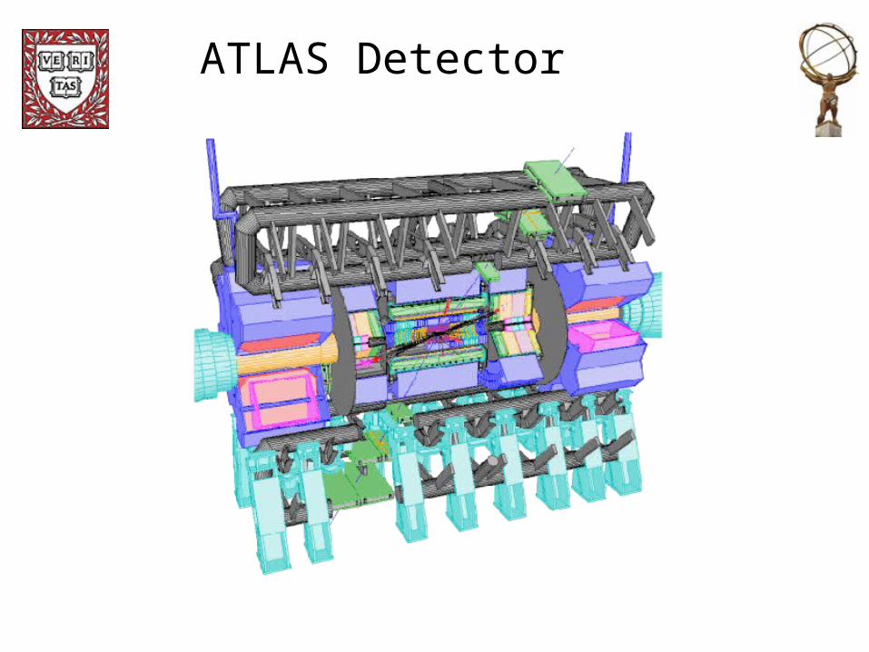
ATLAS Detector

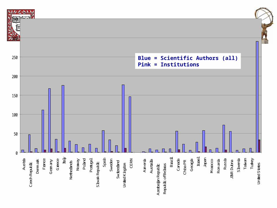
ATLAS Collaboration
34 Countries151 Institutions1770 Scientific Authors
We can be pleased that new groups have initiated the procedure to join:
McGill Montreal (decision at this CB)Bologna (EoI submitted for this CB)
0
50
100
150
200
250
300
350Au
stria
Czec
h Re
publ
ic
Denm
ark
Fran
ce
Ger
man
y
Gre
ece
Italy
Neth
erla
nds
Norw
ay
Pola
nd
Portu
gal
Slov
ak R
epub
lic Spai
n
Swed
en
Switz
erla
nd
Unite
d Ki
ngdo
m
CERN
Arm
enia
Aust
ralia
Azer
baija
n Re
publ
ic
Repu
blic
of B
elar
us Braz
il
Cana
da
Chin
a PR
Geo
rgia
Isra
el
Japa
n
Mor
occo
Rom
ania
Russ
ia
JINR
Dub
na
Slov
enia
Taiw
an
Turk
ey
Unite
d St
ates
Blue = Scientific Authors (all)Pink = Institutions

Speakers age distribution
02468
101214
Age (years)
Entri
es /
2 ye
ars
99 entries (21 F plus 78 M)
441 registered participants
Rome Physics Workshop

Inner Detector: highlights and concerns
• Progress in detector construction is generally satisfactory,
• Concerns:– TRT
• Fuses– SCT
• Low Mass Tapes (LMT) and EndCap schedule– Pixel
• Modules and MCC potting • Stave delamination and fix
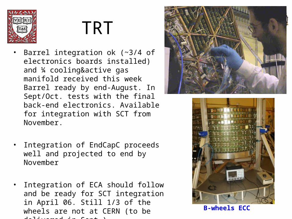
TRT• Barrel integration ok (~3/4 of electronics boards
installed) and ¼ cooling&active gas manifold received this week Barrel ready by end-August. In Sept/Oct. tests with the final back-end electronics. Available for integration with SCT from November.
• Integration of EndCapC proceeds well and projected to end by November
• Integration of ECA should follow and be ready for SCT integration in April 06. Still 1/3 of the wheels are not at CERN (to be delivered in Sept.)
B-wheels ECC

LAr END-CAP A FINAL INTEGRATION
LAr End-Cap A before closure
FCAL A insertion
LAr End-Cap A: Integration is finished, and cool down for acceptance test started.

CTB Barrel Resolution
Mean energy and resolution:
OFC,3x3 cluster
No corrections
Run 2102478Ebeam=180 GeV = 0.3
Same level as inprevious testbeam
<E>
(GeV)
E/<E>
(%)
171.36 0.83
Liquid Argon Calorimter Status
• End-cap C cold test successfully completed. ECC detectors accepted by LAr system.
• End-cap A integration completed, cold test started.
• Front-end electronics production progressing well except
– FEB 6 months delay due to timing problems, trying to recover.
– LV DC/DC power supplies still unpredictable delivery to CERN.
• Back-end electronics production in full swing, installation in USA15 starting with 2 months delay.
• HV PS system improved, but still not stable. Task force to evaluate.
• Barrel FE infrastructure installation well advanced.
• Electronics installation driven by hardware availability. Critical.
• Phase 3 Commissioning organization established.

First Events in the LHC!
Hadronic Tile Cal – on track

Muon SpectrometerMuon Spectrometer
• Trigger System
- Resistive Plate
Chambers (RPC)
- Thin Gap
Chambers (TGC)
• Precision System
- Monitored Drift
Tubes (MDT)
- Cathode Strip
Chambers (CSC)
• Magnet System
- Barrel Toroid (BT)
- Endcap Toroids (ECT)
BTECT
RPCTGC
MDT
CSC
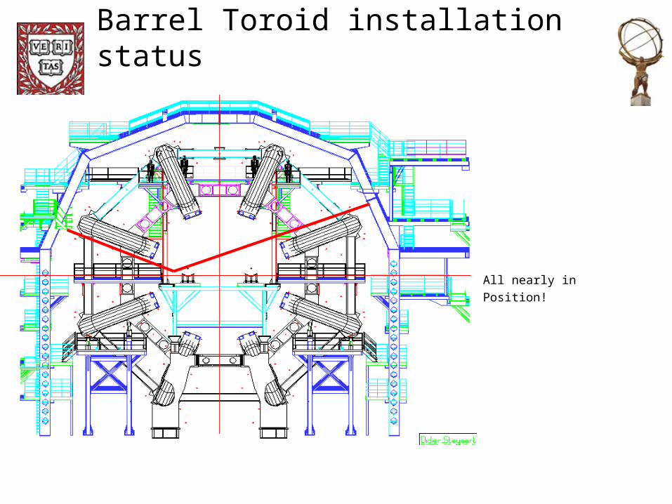
Barrel Toroid installation status
All nearly in
Position!

Barrel Toroid installation

ECT ReorganizationBoth Vacuum vessels at CERN since 2002
Since then we waited
for the Cold mass.............
Company was sold,
2 years delay in production
finally did not qualify production
In May 04 contract was descoped
to coil manufacturing only,
to rescue the project the integration work moved to CERN
In Oct 04 integration work re-started in H191
In April 05 the company completed the coilwinding and all coil units were delivered to CERN

New Cold Mass integration
All bare coils & boxes delivered
New scope in H191:
Repairs on boxes
All Al cooling lines welding
All ss cooling line manifolds
Fix all missing parts
Cold mass survey, shimming
Building up cold mass
Work shows good progress
For CM-C all coils and boxes now ready, lines completed,
assembly of cold mass started

Magnet Schedule
ECT-C
Cold mass ready by Aug 05
Cryostat integrated by Dec 05
80K test in Jan 06 – Mar 06
Transport, installation and test in Apr-Sep 06
ECT-A
Cold mass ready by Jan 06
Cryostat integrated by Apr 06
8K test in May-Jul 06
Transport, installation and test in Sep-Dec 06
BT +2ECT test in Jan-Apr 07

Muon ReconstructionMuon Reconstruction
Aim: ▪ Muon Identification ▪ Precise measurement of muon 3-momentum
(pT)/pT = 10% at pT = 1 TeV/c for most range
requires ~50 m position precision

Basic principleBasic principle
( Physics):
Selection of events with high-pT muons
( Trigger):
Identification of candidate muon tracks coming from the interaction vertex within a pT range.
( Algorithm):
Demand a coincidence of hits in different RPCs chamber within geometrical road.
Similar approach with TGC in endcap
Muon Level 1 Trigger (barrel)Muon Level 1 Trigger (barrel)
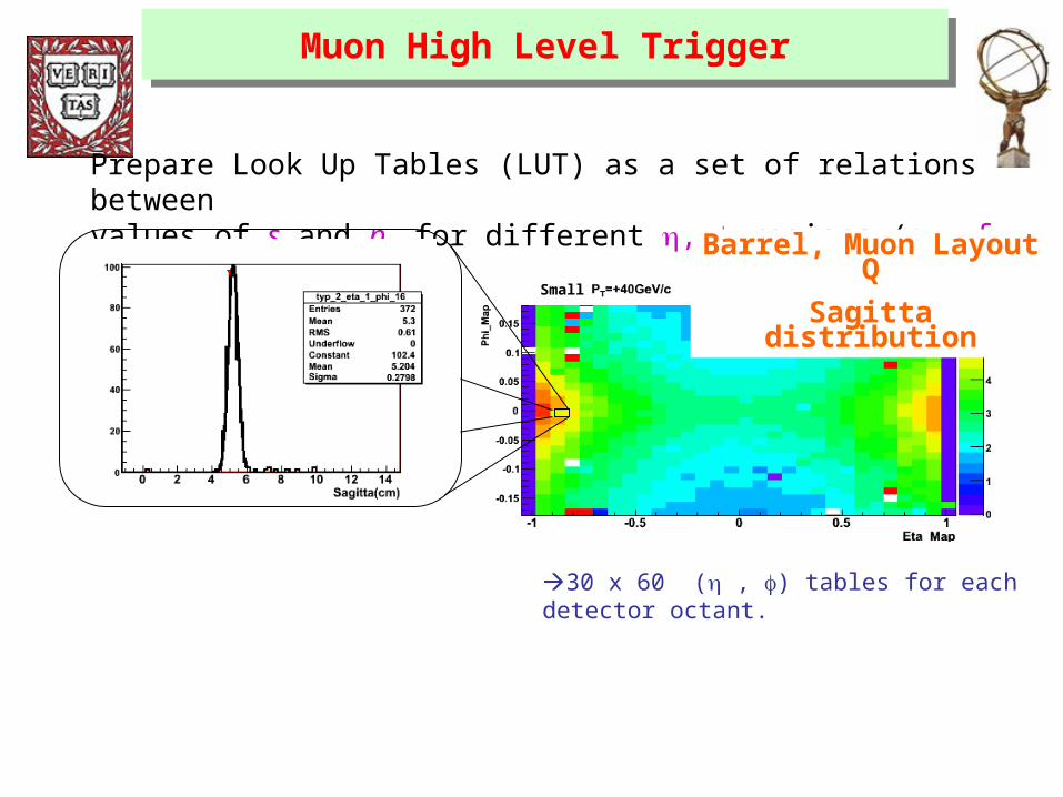
Prepare Look Up Tables (LUT) as a set of relations between values of s and pT for different , regions (s = f ( , , pT)).
Barrel, Muon Layout Q
Sagitta distributionSmall
30 x 60 ( , ) tables for each detector octant.
Muon High Level TriggerMuon High Level Trigger

Moore and
Muonboy able
to reconstruct
tracks
Plan to interface
with dedicated
pattern recogn.
cosmics algorithm
Mooretrack
Cosmics!

LVL1 Trigger Overview
Calorimeter trigger Muon trigger
Central Trigger Processor (CTP)
Timing, Trigger, Control (TTC)
Germany, Sweden, UK
Italy Japan, Israel
Cluster Processor (e/, /h)
Pre-Processor (analogue ET)
Jet / Energy-Sum Processor
CERN
Muon Barrel Trigger
Muon End-cap Trigger
Muon-CTP Interface
(MUCTPI)
~7200 calorimeter trigger towers O(1M) RPC/TGC channels

LVL1 Endcap Muon Trigger• A critical item at the start of this
year was the “SLB” ASIC– Two revised versions of ASIC
evaluated and both work fully– Mass production is in progress
with delivery of packaged devices expected in July
• On-detector electronics using prototype ASICs is available for tests of the 1/12 assemblies– General-purpose boards
Schedule is tight

Trigger Status
• Much progress in all areas of LVL1, HLT and DAQ
• Schedule very tight and particularly critical for the on-detector electronics of the LVL1 muon trigger
– Need to avoid any delays in production, testing, etc.
• Difficult to keep software releases coherent & synchronized, and serving needs both of development & analysis/tuning
– Overall integration and testing is complex and time consuming
• Shortage of effort in a number of areas is a concern
– Some positive recent developments with new people and groups getting involved

Computing
• “Standard model” of computing– Single computing center– Analysis framework– Data management
• Grid computing– Hierarchy of sites
• Tier 0 – CERN – first pass reconstruction• Tier 1 – Regional Centers (BNL = US ATLAS)• Tier 2 – Major clusters

Challenges at the LHC
For each experiment (4 total):
10’s of Petabytes/year of data logged
2000 + Collaborators
40 Countries
160 Institutions (Universities, National Laboratories)
CPU intensive
Global distribution of data
Test with « Data Challenges »

CPU v. Collab.
10
100
1,000
10,000
100,000
0 500 1000 1500 2000 2500
Collaboration Size
CPU CPU v. Collab.
Earth Simulator
Atmospheric Chemistry Group
LHC Exp.
Astronomy
Grav. Wave
Nuclear Exp.
Current accelerator Exp.
CPU vs. Collaboration Size

Image courtesy Harvey Newman, Caltech
Grids for High Energy Physics
Tier2 Centre ~1 TIPS
Online System
Offline Processor Farm
~20 TIPS
CERN Computer Centre
FermiLab ~4 TIPSFrance Regional Centre
Italy Regional Centre
Germany Regional Centre
InstituteInstituteInstituteInstitute ~0.25TIPS
Physicist workstations
~100 MBytes/sec
~100 MBytes/sec
~622 Mbits/sec
~1 MBytes/sec
There is a “bunch crossing” every 25 nsecs.
There are 100 “triggers” per second
Each triggered event is ~1 MByte in size
Physicists work on analysis “channels”.
Each institute will have ~10 physicists working on one or more channels; data for these channels should be cached by the institute server
Physics data cache
~PBytes/sec
~622 Mbits/sec
Tier2 Centre ~1 TIPS
Tier2 Centre ~1 TIPS
Tier2 Centre ~1 TIPS
Caltech ~1 TIPS
~622 Mbits/sec
Tier 0Tier 0
Tier 1Tier 1
Tier 2Tier 2
Tier 4Tier 4
1 TIPS is approximately 25,000
SpecInt95 equivalents
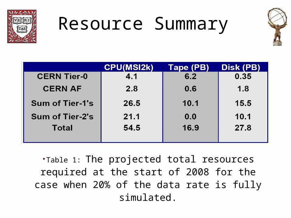
Resource Summary
•Table 1: The projected total resources required at the start of 2008 for the case when 20% of the data rate is fully simulated.

Grid3
virtual data grid laboratory
virtual data research
end-to-end HENPapplications
CERN LHC: US ATLAStestbeds & data challenges
CERN LHC: USCMStestbeds & data challenges
Grid3

Scaling and the Future
• Need to reduce amount of human intervention• Establishment of an economic model for the grid
– What are the real prices of services?– Get beyond “good-will” stage
• Open Science Grid– Next step beyond Grid3
• Security• Data storage and access• Quality of service
• Interoperability among grids– Standards
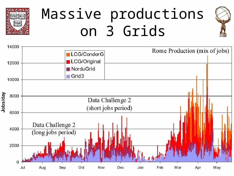
Massive productions on 3 Grids

Massive productions on 3 Grids
• July-September 2004: DC2 Geant-4 simulation (long jobs)
– 40% on LCG/EGEE Grid, 30% on Grid3 and 30% on NorduGrid
• October-December 2004: DC2 digitization and reconstruction (short jobs)
• February-May 2005: Rome production (mix of jobs as digitization and reconstruction was started as soon as samples had been simulated)
– 70% on LCG/EGEE Grid, 25% on Grid3, 5% on NorduGrid

Rome Grid Production: Successful Job Count at 83 ATLAS sites
Southwest T2 BNL T1
Boston T2
Midwest T2

U.S. Grid Production (Rome/DC2 combined)
20 different sites used in the U.S.
ATLAS Tier 2’s played dominant role
BNL T122%
Boston T220%
UM3%
UBuf2%
PSU3%
Southwest T224%
FNAL4%
PDSF4%
Midwest T213%
Other US sites (7)4%
UCSD1%
(3 sites)
(2 sites)

US ATLAS Domination on Grid3
<Capone Jobs/day> = 350
Max # jobs/day = 1020
US ATLAS dominated all other VOs in use of Grid3
2004 2005
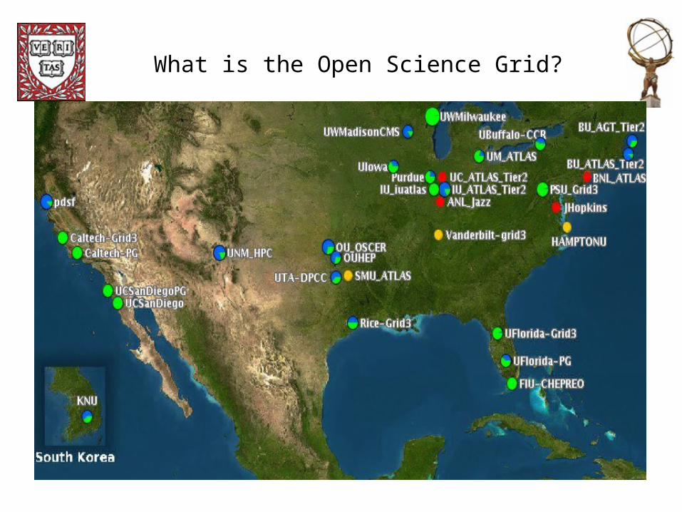
What is the Open Science Grid?

Consortium Architecture

What is the Open Science Grid?
• Open
– A new sort of multidisciplinary cyberinfrastructure community
– An experiment in governance, incentives, architecture
– Part of a larger whole, with TeraGrid, EGEE, LCG, etc.
• Science
– Driven by demanding scientific goals and projects who need results today (or yesterday)
– Also a computer science experimental platform
• Grid
– Standardized protocols and interfaces
– Software implementing infrastructure, services, applications
– Physical infrastructure—computing, storage, networks
• People who know & understand these things!

US ATLAS Roles in Cyberinfrastructure
• US ATLAS played leadership roles in Grid3 – Overall project coordination, led monitoring and metrics group, led operations,
deployed the iGOC and iVDGL prototype Tier2 centers, led the deployment of Grid3 infrastructure and services overall
– Largest user of Grid3 resources 2004, 2005• Leadership roles in the Open Science Grid
– Integration (UC and IU lead), Deployment (BNL co-chairs), Interoperability with LCG/EGEE and TeraGrid (IU co-chairs), Operations (IU co-chairs), OSG GOC (IU hosting), Consortium architecture and Governance (BNL, BU, HU, UC)
– US ATLAS is heavily involved in defining the set of US LHC baseline services required for the OSG
• Leadership roles in the international ATLAS grid production system– Windmill Supervisor: ATLAS interoperating with Grid3, LCG, and NorduGrid– Pacman, software environment manager: used by ATLAS, VDT, Grid3, OSG,
LCG, Green Grid, CMS/DPE, SRM, the French Ministry of Education, LIGO, being evaluated by TeraGrid, STAR, and others
– Capone, workload management system for Grid3
Summary
• Accelerator and ATLAS are on schedule for 2007– Not to say that things aren’t very tight– Small problems
• First cosmic rays seen in partly assembled detector.
• Major work on muon subsystem – installation, reconstruction, computing grids (next talks).