7810083 rev: f
TRANSCRIPT

7810083R
ev: F
Always read all instruction completely before commencing installation
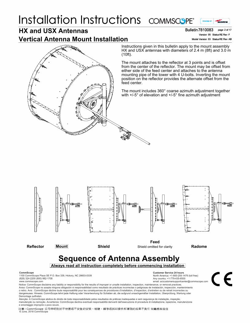
Instructions given in this bulletin apply to the mount assembly HX and USX antennas with diameters of 2.4 m (8ft) and 3.0 m (10ft).
The mount attaches to the reflector at 3 points and is offset from the center of the reflector. The mount may be offset from either side of the feed center and attaches to the antenna mounting pipe of the tower with 4 U-bolts. Inverting the mount position on the reflector provides the alternate offset from the feed center.
The mount includes 360° coarse azimuth adjustment together with +/-5° of elevation and +/-5° fine azimuth adjustment
Sequence of Antenna AssemblyMount Radome
FeedShield omitted for clarityShieldReflector
7810083
ABRE03
Bulletin
RevStatusModel Version
Version RevStatus
2 of 17page
Installation InstructionsFRE05
HX and USX AntennasVertical Antenna Mount Installation
7810083
ABRE03
Bulletin
RevStatusModel Version
Version RevStatus
2 of 17page
Installation InstructionsFRE05
© June, 2018 CommScope
Notice: CommScope disclaims any liability or responsibility for the results of improper or unsafe installation, inspection, maintenance, or removal practices.Aviso: CommScope no acepta ninguna obligación ni responsabilidad como resultado de prácticas incorrectas o peligrosas de instalación, inspección, mantenimiento o retiro. Avis : CommScope décline toute responsabilité pour les conséquences de procédures d’installation, d’inspection, d’entretien ou de retrait incorrectes ou dangereuses. Hinweis: CommScope lehnt jede Haftung oder Verantwortung für Schäden ab, die aufgrund unsachgemäßer Installation, Überprüfung, Wartung oder Demontage auftreten.Atenção: A CommScope abdica do direito de toda responsabilidade pelos resultados de práticas inadequadas e sem segurança de instalação, inspeção, manutenção ou remoção. Avvertenza: CommScope declina eventuali responsabilità derivanti dell’esecuzione di procedure di installazione, ispezione, manutenzione e smontaggio improprie o poco sicure.
CommScope1100 CommScope Place SE P.O. Box 339, Hickory, NC 28603-0339(828) 324-2200 (800) 982-1708www.commscope.com
Customer Service 24 hoursNorth America: +1-800-255-1479 (toll free)Any country: +1-779-435-6500email: [email protected]

Page 3 of 177810083
CONTENTS & INTRODUCTIONSECTION 1INSTALLATION
INSTRUCTIONS

Page 4 of 177810083
SAFETY INSTRUCTIONSSECTION 2INSTALLATION
INSTRUCTIONS

Page 5 of 177810083
SAFETY INSTRUCTIONSSECTION 2INSTALLATION
INSTRUCTIONS

Tightening of hardwareIt is recommended that all hardware is tightened to the torques specified in table 3.The integrity of the mount depends on all fasteners being properly tightened.
Fastener Torque Specifications
INSTALLATION INSTRUCTIONS
SECTION 3COMPONENTS AND TOOLS
7810083Page 6 of 17
Fastener material
- M10 M12 M16 M20
Galvanized38 60 95 185
(28) (44.3) (70) (136.4)
Brass- - - 95
- - - (70)
Tools Required M10 M12 M16 M20Ring and Open spanner (A/F) 17mm 19mm 24mm 30mm
Torque Wrench
Sockets (A/F) 17mm 19mm 24mm 30mm
General Toolbox

AB
C
D
E (10ft Only)
F (10ft Only)
(Side strut for 10ft only)
INSTALLATION INSTRUCTIONS
SECTION 3COMPONENTS AND TOOLS
7810083Page 7 of 17
Components
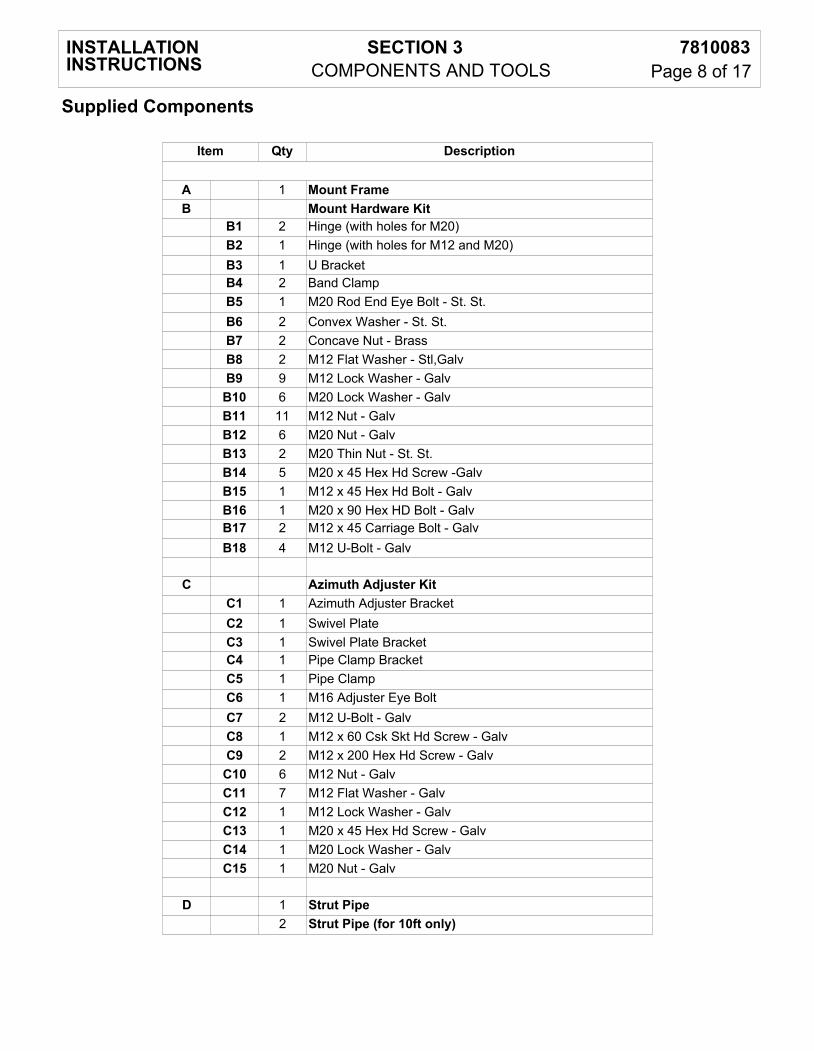
Supplied Components
INSTALLATION INSTRUCTIONS
SECTION 3COMPONENTS AND TOOLS
7810083Page 8 of 17
Item Qty Description
A 1 Mount FrameB Mount Hardware Kit
B1 2 Hinge (with holes for M20)B2 1 Hinge (with holes for M12 and M20)B3 1 U BracketB4 2 Band ClampB5 1 M20 Rod End Eye Bolt - St. St.B6 2 Convex Washer - St. St.B7 2 Concave Nut - BrassB8 2 M12 Flat Washer - Stl,GalvB9 9 M12 Lock Washer - GalvB10 6 M20 Lock Washer - GalvB11 11 M12 Nut - GalvB12 6 M20 Nut - GalvB13 2 M20 Thin Nut - St. St.B14 5 M20 x 45 Hex Hd Screw -GalvB15 1 M12 x 45 Hex Hd Bolt - GalvB16 1 M20 x 90 Hex HD Bolt - GalvB17 2 M12 x 45 Carriage Bolt - GalvB18 4 M12 U-Bolt - Galv
C Azimuth Adjuster KitC1 1 Azimuth Adjuster BracketC2 1 Swivel PlateC3 1 Swivel Plate BracketC4 1 Pipe Clamp BracketC5 1 Pipe ClampC6 1 M16 Adjuster Eye BoltC7 2 M12 U-Bolt - GalvC8 1 M12 x 60 Csk Skt Hd Screw - GalvC9 2 M12 x 200 Hex Hd Screw - GalvC10 6 M12 Nut - GalvC11 7 M12 Flat Washer - GalvC12 1 M12 Lock Washer - GalvC13 1 M20 x 45 Hex Hd Screw - GalvC14 1 M20 Lock Washer - GalvC15 1 M20 Nut - Galv
D 1 Strut Pipe2 Strut Pipe (for 10ft only)

Supplied Components
INSTALLATION INSTRUCTIONS
SECTION 3COMPONENTS AND TOOLS
7810083Page 9 of 17
Item Qty Description
E Side Strut Tower Clamp Kit (for 10ft only)E1 1 Swivel Plate BracketE2 1 Pipe Clamp BracketE3 1 Pipe ClampE4 1 M12 U-Bolt - GalvE5 2 M12 x 200 Hex Hd Screw - GalvE6 4 M12 Nut - GalvE7 4 M12 Flat Washer - GalvE8 3 M20 x 45 Hex Hd Screw - GalvE9 4 M20 Lock Washer - GalvE10 4 M20 Nut - GalvE11 1 U BracketE12 1 M20 x 90 x 46 Hex Hd Bolt - GalvE13 1 Strut Angle Bracket
F Side Strut Anchor Bracket Kit (for 10ft only)F1 1 Side Strut BracketF2 4 M10 x 35 Hex Hd Screw - GalvF3 8 M10 Large Washer - GalvF4 2 Washer, BarF5 4 M10 Lock Washer - GalvF6 4 M10 Nut - Galv

B14
B3B1
B14
A
B10
B12
B14A B10 B12
B1B14
B2B15
B14
B13B7
B6
A
B9
B11
B5
178mm (7")
B13 B7 B6 B6 B7B13
B5
INSTALLATION INSTRUCTIONS
SECTION 4MOUNT FRAME ATTACHMENT
7810083Page 10 of 17
Assemble loosely
Mount assembly

tighten to a torque of 185Nm +/-5%
tighten to a torque of 185Nm+/-5%
Offset Left - Standard
Top of reflectormarked withred tape
Guywirelocation
Offset Right - Inverted
Top of reflectormarked withred tape
Guywirelocation
INSTALLATION INSTRUCTIONS
SECTION 4MOUNT FRAME ATTACHMENT
7810083Page 11 of 17
Mount attachment to reflector

B16
B10
B12
D
C7 C6
C7
C8
C3
C15
C14
C2
C9
C11
C13
C5
C11
C10C10
C10
C11 C10 C11
C12
C11
C1
C4
INSTALLATION INSTRUCTIONS
SECTION 5STRUT ATTACHMENT
7810083Page 12 of 17

D
D
F1
F2F3
F2F3
F3 E10E9
E8
E12
E11
E9E10
F5F6
F6
F5
F4
F5
F6
E13
F4
E1
E2
E3
E4
E5
E6
E6
E7
E7
E8
E9E10
INSTALLATION INSTRUCTIONS
SECTION 5STRUT ATTACHMENT
7810083Page 13 of 17
Installation Instruction on this page for 10ft only

Tower structuralmember
B11
B8
B4B17
Tower structuralmember
Tighten to a torqueof 60Nm 5%
Assemble Loosely
Strut removed for clarity
The lean angle can be stabilised using an appropriate location at the antenna rim
B18
B11B9
B11
B9
B18
INSTALLATION INSTRUCTIONS
SECTION 6 ATTACHMENT TO TOWER
7810083Page 14 of 17
Attachment to tower
SUGGESTED HOISTING
NEVER WALK UNDER HOISTED LOADS
The antenna weight should be lifted from a suitable load bearing location as shown

Attachment to circular structural members
Min 48mmMax 120mm
Min 50mm x 50mmMax 90MM x 90mm
Do not attach tounequal angles
Attachment to non-circular structural members
INSTALLATION INSTRUCTIONS
SECTION 7TOWER CLAMP ATTACHMENT
7810083Page 15 of 17
Clamp must be attached to a circular or non-circular structural member capable of supporting 11263N in accordance with TIA-222
The maximum allowable relative deflection between the antenna mounting pipe and the strut attachment must be less than 2mm at survival wind speed of the antenna.
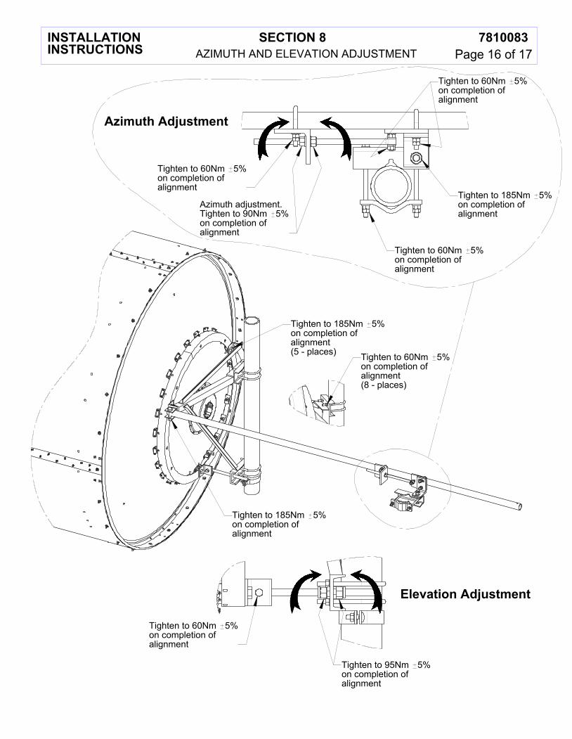
Elevation Adjustment
Azimuth Adjustment
Azimuth adjustment.Tighten to 90Nm 5%on completion ofalignment
Tighten to 60Nm 5%on completion ofalignment
Tighten to 60Nm 5%on completion ofalignment
Tighten to 60Nm 5%on completion ofalignment
Tighten to 185Nm 5%on completion ofalignment
INSTALLATION INSTRUCTIONS
SECTION 8AZIMUTH AND ELEVATION ADJUSTMENT
7810083Page 16 of 17
Tighten to 95Nm 5%on completion ofalignment
Tighten to 60Nm 5%on completion ofalignment
Tighten to 60Nm 5%on completion ofalignment(8 - places)
Tighten to 185Nm 5%on completion ofalignment(5 - places)
Tighten to 185Nm 5%on completion ofalignment

25 Azimuth
15 Elevation
25°Azimuth
15°Elevation
Side strut for 10ft only
INSTALLATION INSTRUCTIONS
SECTION 9ANGULAR LIMITS OF STRUT
7810083Page 17 of 17
Limits of strut position forattachment to tower member